automatic transfer switch otm c20d - abb group · otm_c20d must be in auto mode and the auto led is...
TRANSCRIPT

Automatic Transfer Switch OTM_C20D
Installation and Operation Instructions
ABB Xinhui Low Voltage Switchgear Company LimitedJinguzhou Industrial Zone, Xinhui District, JiangmenCity, Guangdong Province, PRCPostal code: 529100Tel: +86-750-6322200Fax: +86-750-6677526http://www.abb.com.cn 2T
FR70
003
1A10
01-
A
v Read through this instruction carefully before working on the switch,and keep this instruction for later reference
v The images provided in this instruction book are for illustrationpurposes only and may not match the actual product exactly
v This instruction is subject to change for product updates without priornotice

16
9 Appendix
9.1 Wiring diagram
Figure 20 Wiring Diagram

Contents
1 SYMBOLS & TERMS ............................................................................................................. 1
1.1 USE OF SYMBOLS ................................................................................................................................. 1
1.2 EXPLANATIONS OF ABBREVIATIONS AND TERMS...................................................................................... 1
2 PRODUCT OVERVIEW .......................................................................................................... 2
2.1 PRODUCT OVERVIEW AND PACKING ....................................................................................................... 2
2.2 OTM_C20D SWITCHING SEQUENCE .....................................................................................................3
2.2.1 Line 1 Priority (default mode) .......................................................................................................3
2.2.2 No line priority ................................................................................................................................3
3 QUICK START ....................................................................................................................... 4
3.1 OPERATING THE SWITCH MANUALLY (LOCAL OPERATION) ...................................................................... 4
3.2 AUTOMATIC OPERATION ...................................................................................................................... 5
3.3 LOCAL TEST OPERATION ...................................................................................................................... 6
3.4 LOCKING ............................................................................................................................................. 7
3.4.1 Locking the electrical operation .................................................................................................. 7
3.4.2 Locking the manual operation ..................................................................................................... 7
4 INTERFACE AND SETTINGS ................................................................................................. 8
4.1 BUTTONS ........................................................................................................................................... 8
4.2 LEDS ................................................................................................................................................. 8
4.3 DIP SWITCH SETTING .......................................................................................................................... 9
4.4 TERMINAL .......................................................................................................................................... 9
5 TECHNICAL DATA .............................................................................................................. 10
6 INSTALLATION ................................................................................................................... 10
6.1 INSTALLATION METHOD ...................................................................................................................... 10
6.2 INSTALLATION DIMENSIONS ................................................................................................................ 12
7 OPTIONAL ACCESSORIES ................................................................................................. 13
7.1 BRIDGING BARS .................................................................................................................................. 13
7.2 TERMINAL SHROUDS .......................................................................................................................... 14
7.3 AUXILIARY CONTACT BLOCKS .............................................................................................................. 14
8 MAINTENANCE AND TROUBLESHOOTING ....................................................................... 15
8.1 MAINTENANCE .................................................................................................................................. 15
8.2 TROUBLESHOOTING ........................................................................................................................... 15
9 APPENDIX .......................................................................................................................... 16
9.1 WIRING DIAGRAM ............................................................................................................................... 16
15
8 Maintenance and troubleshooting
8.1 Maintenance
To ensure the operation reliability of switches, regular switching tests should beperformed (once every 3 months) to confirm normal function.
8.2 Troubleshooting
No. Fault Description Fault Analysis Troubleshooting Method1 Power supply
functioning normally,but LED not ON
Control unit powersupply terminal notconnected withswitch wiringterminal
Check and connect theswitch wiring terminal.
2 Power supply LEDfunctioning normallybut Auto LED OFF, or noresponse with AUTObutton pressed
Handle not pulledout or electricalpadlock notremoved
Pull out the handle orremove the padlock,and then press theAUTO button.
3 Transition failure in caseof faulty power supply
1. Switch notoperating in AUTOmode2. Both LN1 and LN2malfunctioning
Make sure the switch isworking in AUTO mode.Check and make sureboth LN1 and LN2 arenot malfunctioningsimultaneously.
4 EMRG OFF functionfailure
1. Check if the EMRGOFF signal is 24V DC2. Too shortduration of EMRGOFF signal
Correctly switch on theEMRG OFF signal,which should only be24V DC with theduration ≥ 1 s.
5 Auto LED blinking withall other LEDs OFFNo response frombuttons
DIP switch for polesnumber of powersupply set to “00”
Check if the DIP switchsetup matches thephase number ofswitch power supply.
6 I or II LED blinking Operation failureduring switching,thus expected resultnot achieved
Manually set the switchto Position O, and pressthe AUTO button toreset.
Table 5 Troubleshooting

1
1 Symbols & Terms
1.1 Use of symbols
Hazardous voltage: warns about a situation where a hazardousvoltage may cause physical injury to a person or damage toequipment.
General warning: warns about a situation where something otherthan electrical equipment may cause physical injury to a person ordamage to equipment.
Caution: provides important information or warns about a situationthat may have a detrimental effect on equipment.
Information: provides important information about the equipment.
1.2 Explanations of abbreviations and terms
OTM_C20D Automatic transfer switch, the type nameLN1 Power supply line, the primary lineLN2 Power supply line, the secondary line used in emergency
casesEMRG OFF Used to drive the automatic transfer switch transfers to
the O position when receiving EMRG OFF signal.
AUTO Automatic modeTEST The switch performs “switching cycle test” as the pre-set
programTable 1 Explanations of abbreviations and terms
Hazardous voltage! The operation, installation andservicing of this appliance must be carried out by aqualified electrician applying the relevant rules of theart, Installation standards and safety regulations. Do nottouch live parts. Danger!
14
7.2 Terminal shrouds
Figure 18 Terminal shrouds
7.3 Auxiliary contact blocks
Figure 19 Auxiliary contact blocks
OTS125T3
OTS125T1
○1
○2
○3
○4
OA7G10 OA1G01Contact NO NC
I
O
II
Max 2 pcs
OA1G10 OA8G01Contact NO NC
I
O
II
Max 2 pcs
0.8Nm
0.75 - 2.5 mm218 – 14 AWG

2
2 Product overview
2.1 Product overview and packing
The OTM_C20D automatic transfer switches can be used as a source transferswitch in a three-phase or single-phase networks. Monitored conditions are, no-voltage and phase-loss. You can operate the switch, either manually with thehandle or automatically by the AUTO mode. The automatic operation modesinclude Line 1 priority and no line priority.
Figure 1 OTM_C20D automatic transfer switch
1. Handle for manual operation2. Place for auxiliary contact blocks3. Push button4. Mimic panel5. Voltage sensing connections6. Locking clip for padlock
7. Locking latch for releasing thehandle and locking electrical control
8. Locking clip for locking manualoperation
9. DIP switches10. Connecting terminal
The standard package includes: 1.automatic transfer switch, 2.handle, 3.handlestorage clip 4.terminal plug, 5.mounting kit
12
3
45
6
78
9
10
13
7 Optional accessories
7.1 Bridging bars
Figure 17 Bridging bars
6 Nm
Number of conductors ≤210 - 70 mm2 , 8 - 00 AWG
17
OTM32~125F2C20D OMZC03OTM32~125F3C20DOTM32~125F4C20D OMZC04
Number of conductors ≤210 - 70 mm2 , 8 - 00 AWG
6 Nm
17

3
2.2 OTM_C20D switching sequence
2.2.1 Line 1 Priority (default mode)
The switching sequence can be summarized in following steps:l A fault occurs on LN1, while LN2 functions normallyl Transfer switch (Switch I) to the position 0l Transfer switch (Switch II) to the position II
And the back switching sequence can be summarized in the following steps:l The LN1 will start the normal functioningl Transfer switch (Switch II) to the position 0l Transfer switch (Switch I) to the position I
Figure 2 Automatic Switching Sequences in OTM_C20D, Line 1 priority
2.2.2 No line priority
The switching sequence can be summarized in following steps:l A fault occurs on LN1, while LN2 functions normallyl Transfer switch (Switch I) to the position 0l Transfer switch (Switch II) to the position II
And the back switching sequence can be summarized in the following steps:l The LN1 will start the normal functioningl Transfer switch stays in position IIl A fault occurs on the LN2l Transfer switch (Switch II) to the position 0l Transfer switch (Switch I) to the position I
Figure 3 Automatic Switching Sequences in OTM_C20D, No line priority
12
6.2 Installation dimensions
Figure 16 Dimensions
4
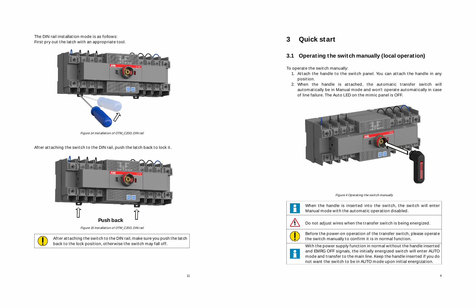
3 Quick start
3.1 Operating the switch manually (local operation)
To operate the switch manually:1. Attach the handle to the switch panel. You can attach the handle in any
position.2. When the handle is attached, the automatic transfer switch will
automatically be in Manual mode and won’t operate automatically in caseof line failure. The Auto LED on the mimic panel is OFF.
Figure 4 Operating the switch manually
When the handle is inserted into the switch, the switch will enterManual mode with the automatic operation disabled.
Do not adjust wires when the transfer switch is being energized.
Before the power-on operation of the transfer switch, please operatethe switch manually to confirm it is in normal function.
With the power supply function in normal without the handle insertedand EMRG OFF signals, the initially energized switch will enter AUTOmode and transfer to the main line. Keep the handle inserted if you donot want the switch to be in AUTO mode upon initial energization.
11
The DIN rail installation mode is as follows:First pry out the latch with an appropriate tool.
Figure 14 Installation of OTM_C20D, DIN rail
After attaching the switch to the DIN rail, push the latch back to lock it.
Figure 15 Installation of OTM_C20D, DIN rail
After attaching the switch to the DIN rail, make sure you push the latchback to the lock position, otherwise the switch may fall off.
Push back

5
3.2 Automatic operation
OTM_C20D must be in AUTO mode and the Auto LED is ON in order that theswitch can perform automatic transfer cycles according to the pre-set operatingmode.
To operate the switch automatically:l If the handle inserted,
1. Press handle locking clip and remove the handle from the switch.2. Press AUTO button and the Auto LED will be ON, indicating AUTO mode.
l If handle is not inserted1. If Auto LED blinks or OFF, press AUTO button and the Auto LED will be ON,
indicating AUTO mode.2. Automatic operation includes two operating modes: Line 1 priority
(default setting) and No line priority.
Figure 5 operate the automatic transfer OTM_C20D to Auto mode
○3
○2
○1
10
5 Technical data
Automatic transfer switch ParametersRated operational voltage Ue 220~240VAC(2P) 380~415VAC(3P/4P)
50~60 HzOperating voltage range 0.8~1.2 Ue
Accuracy ±5%Operating angle 90° ( O-I, I-O, O-II, II-O) 180° ( I-O-II, II-O-I)OFF time 610 ms ± 10%Electromagnetic compatibility Class BIngress Protection Rating IP20, front panelRated impulse withstandvoltage Uimp
8 kV (6 kV for control circuit, disconnect thepower line of the control circuit before thedielectric voltage withstand test)
Operating temperature -25~55℃Transportation and storagetemperature
-40~70℃
Altitude Max. 2000 mTable 4 Technical data
6 Installation
6.1 Installation method
The switch can be installed using screws or a DIN rail.The fixed installation mode on the base board is as follows:
Figure 13 Installation of OTM_C20D, screw
M4 2 Nm

6
3.3 Local test operation
In AUTO mode, Auto LED is ON and you can press the TEST button on the panelto lead it to TEST mode:
Operation sequence:1. Ensure switch in AUTO mode2. Press the TEST button and the Auto LED will blink, indicating the activation of
TEST mode.Under TEST mode, the automatic transfer switch will transfer by one cycleand finally return to its original position.e.g., when the switch is in Position I:Press the TEST button; the switch transfers to Position Oà to Position IIà toPosition Oà to Position I.During process, pressing the TEST button again will be invalid until it returnsto its original position.During TEST process, press the AUTO button will cancel TEST mode andreturn to AUTO mode.
3. After test, press AUTO button to return the automatic operation.
Figure 6 Local test of OTM_C20D
In the test sequence, the main power supply circuit will be closed.
If the test sequence is interrupted due to power failure, the automatictransfer switch will enter AUTO mode after power recovery.
9
4.3 DIP switch settingThe DIP switch is used to set the operation modes and poles of transfer switch.
Figure 11 DIP switch
No. Function Setting1, 2 Pole
setting01 10 11 002 poles 3 poles 4 poles Invalid
setting3 Mode
setting0 1No line priority Line 1 priority
Table 3 DIP switch
The 3-bit DIP switch is used to control the switch for circuit testing,and the mismatch with the load power supply will result in testing andtransfer failure. Therefore, carefully read this guide and set correctparameters based on the actual situation before using this product.
4.4 TerminalEMRG OFF: Input the 24VDC EMRG OFF signals (no distinction between thepositive and negative) for at least 1s until the switch transfers to the O positionand the EMRG OFF LED is on. At this time, the switch cannot enter the AUTO orTEST mode and only manual operation is allowed. After the signal is canceled,press "AUTO" to quit EMRG OFF mode.
Figure 12 EMRG OFF terminal

7
3.4 Locking
3.4.1 Locking the electrical operation
The switch can be padlocked in any position, causing that all operating modesand test operations are disabled and handle cannot be inserted. See below foroperation:
Figure 7 Locking the electrical operation
3.4.2 Locking the manual operation
By default, the manual operation can only be locked in position O. The handle canbe padlocked by pulling out the clip from the handle and placing the padlock onthe handle. Maximum 3 padlocks.
Figure 8 Locking the manual operation
φ 5-6 mm
○1
○2○3
○4φ 5-6 mm
8
4 Interface and Settings
4.1 Buttons
Figure 9 Buttons of OTM_C20D
AUTO buttonIt can lead to AUTO mode. When the switch is in Test mode or fault status, pressthe AUTO button until the Auto LED on.TEST buttonIt can lead to TEST mode. First it must on AUTO mode, then press the TESTbutton while the Auto LED blinking. You must press the AUTO button after thetest is complete.
4.2 LEDs
Figure 10 LEDs of OTM_C20D
LED Display Status descriptionLN1/LN2 ON Power normally
Blinking Phase lossOFF No voltage
I/II ON Switch I or II closedOFF Switch I or II openBlinking Switching failure.
Auto ON Transfer switch in AUTO modeBlinking Transfer switch in TEST mode or invalid
settingOFF Transfer switch in manual mode
EMRG OFF ON Received emergency signalsOFF No emergency signals input
Table 2 LEDs