automatic transmission/transaxle: all technical service...
TRANSCRIPT

1999 Ford Truck Explorer 2WD V6-245 4.0L VIN X SFI Page 1
Automatic Transmission/Transaxle: All Technical Service BulletinsTechnical Service Bulletin # 99-7-8 Date: 990419
Transmission Crossmember - New Service KitArticle No.99-7-8
04/19/99
TRANSMISSION - CROSSMEMBER - NEW SERVICEKIT - 4X2 OR 4X4
LIGHT TRUCK:1998-99 EXPLORER, RANGER
ISSUEWhen servicing a transmission, and/or removal of the transmission crossmember, the fasteners and/or crossmember may break or become damaged. Anew service Transmission Crossmember Kit has been released to fix these fasteners that have been broken or stripped, and/or to repair transmissioncrossmembers that have been damaged.
ACTIONInstall new Transmission Crossmember Kit. Refer to the following Service Procedure for details.
SERVICE PROCEDURE
NOTEWHEN REMOVING THE EXISTING TRANSMISSION CROSSMEMBER FOR SERVICE, USE APPROPRIATE WRENCH AND/ORSOCKET-SET PRIOR TO USING AN AIR IMPACT GUN. AN AIR IMPACT GUN WILL MORE THAN LIKELY IMMEDIATELY STRIPAND/OR BREAK THE BOLT WHICH WILL ADD MORE LABOR TIME FOR REPAIR.
1. Remove existing transmission crossmember.
2. If bolts or J-clips have broken during the attempt for removal, drill out subject bolts.
3. Install appropriate Transmission Crossmember (Ranger 4X2 - F87Z-6A023-AA; Ranger 4X4 and all Explorer - F87Z-6A023-BA). For Ranger4X4 and Explorers, it is important to install the provided spacers (2) in the C-channel of the crossmember. Reference the existing transmissioncrossmember. Refer to the appropriate Ranger/Explorer Workshop Manual for further details.
When fastening the transmission crossmember bolts torque to the specification found in the chart as shown.
PART NUMBER PART NAME
F87Z-6A023-AA Transmission Crossmember (Ranger4X2)
F87Z-6AO23-BA Transmission Crossmember (Ranger4X4 And Explorer)
OTHER APPLICABLE ARTICLES: NONE WARRANTY STATUS: Eligible Under The Provisions Of Bumper To Bumper Warranty Coverage
OPERATION DESCRIPTION TIME
990708A Replace Transmission 0.8 Hr.Crossmember (4X2)

1999 Ford Truck Explorer 2WD V6-245 4.0L VIN X SFI Page 2
990708B Replace Transmission 0.6 Hr.Crossmember (4X4)
DEALER CODINGCONDITION
BASIC PART NO. CODE5005 01
OASIS CODES: 305000, 504000, 505000Technical Service Bulletin # 99-15-2 Date: 990726
A/T - Transmission Flush and Fill Tool AvailableArticle No99-15-2
07/26/99
TRANSMISSION - NEW TRANSMISSION FLUSH AND FILL TOOL AVAILABLE THROUGH ROTUNDA
FORD: 1985-1994 TEMPO1985-1997 THUNDERBIRD1985-1999 CROWN VICTORIA, ESCORT, MUSTANG1986-1999 TAURUS1988-1993 FESTIVA1993-1997 PROBE1994-1997 ASPIRE1995-1999 CONTOUR1985-1990 BRONCO II1985-1996 BRONCO1985-1997 F-250 HD, F-3501985-1999 ECONOLINE, F-250 LD, RANGER1986-1997 AEROSTAR1988-1997 F SUPER DUTY1991-1999 EXPLORER1995-1999 WINDSTAR1997-1999 EXPEDITION1999 SUPER DUTY F SERIES
LINCOLN:1985-1992 MARK VII1985-1999 CONTINENTAL, TOWN CAR1993-1998 MARK VIII1998-1999 NAVIGATOR
MERCURY:1985-1994 TOPAZ1985-1997 COUGAR1985-1999 GRAND MARQUIS1986-1999 SABLE1991-1999 TRACER1995-1999 MYSTIQUE1999 COUGAR1997-1999 MOUNTAINEER
ISSUEA new flush and fill tool has been released. This improved design simplifies fluid exchange within the vehicle.
ACTIONThe TransServe(R) II (Rotunda 211-0018) is a more effective way to change the transmission fluid and remove the old contaminated fluid in thesystem. The TransServe(R) II may be used any time the transmission fluid needs replacement. Refer to the 19g9 Rotunda Equipment Catalog for moreinformation.
OTHER APPLICABLE ARTICLES: NONE
1999 Ford Truck Explorer 2WD V6-245 4.0L VIN X SFI Page 3
WARRANTY STATUS: INFORMATION ONLY
OASIS CODES: 504000Technical Service Bulletin # 00-23-10 Date: 001113
A/T - In Line Fluid Filter KitArticle No.00-23-10
11/13/00
TRANSMISSION - FLUID IN - LINE FILTER KIT - REPEAT REPAIRS OF TRANSMISSION - SERVICE TIPS
FORD:1980-1997 THUNDERBIRD1980-2001 CROWN VICTORIA1984-2001 MUSTANG1985-1990 BRONCO II1985-2001 RANGER1987-1997 AEROSTAR1989-1996 BRONCO1989-1997 F SUPER DUTY, F-250 HD1989-2001 ECONOLINE, F-150, F-250 LD, F-350, F-4501991-2002 EXPLORER1997-2001 EXPEDITION1999-2001 F-250 HD, SUPER DUTY F SERIES2000-2001 EXCURSION
LINCOLN:1982-2001 TOWN CAR2000-2001 LS1998-2001 NAVIGATOR
MERCURY:1980-2001 GRAND MARQUIS1987-1997 COUGAR1997-2002 MOUNTAINEER
This TSB article is being republished in its entirety to update model applications and model years.
ISSUEContamination from prior transmission concerns or excess wear may be trapped in the transmission fluid cooling system. This debris must be removedby properly cleaning the transmission cooling system. After cleaning, some contamination may still remain. The remaining contamination may bereintroduced into the fluid cooling system of a repaired/replaced transmission causing premature or repeat failures.
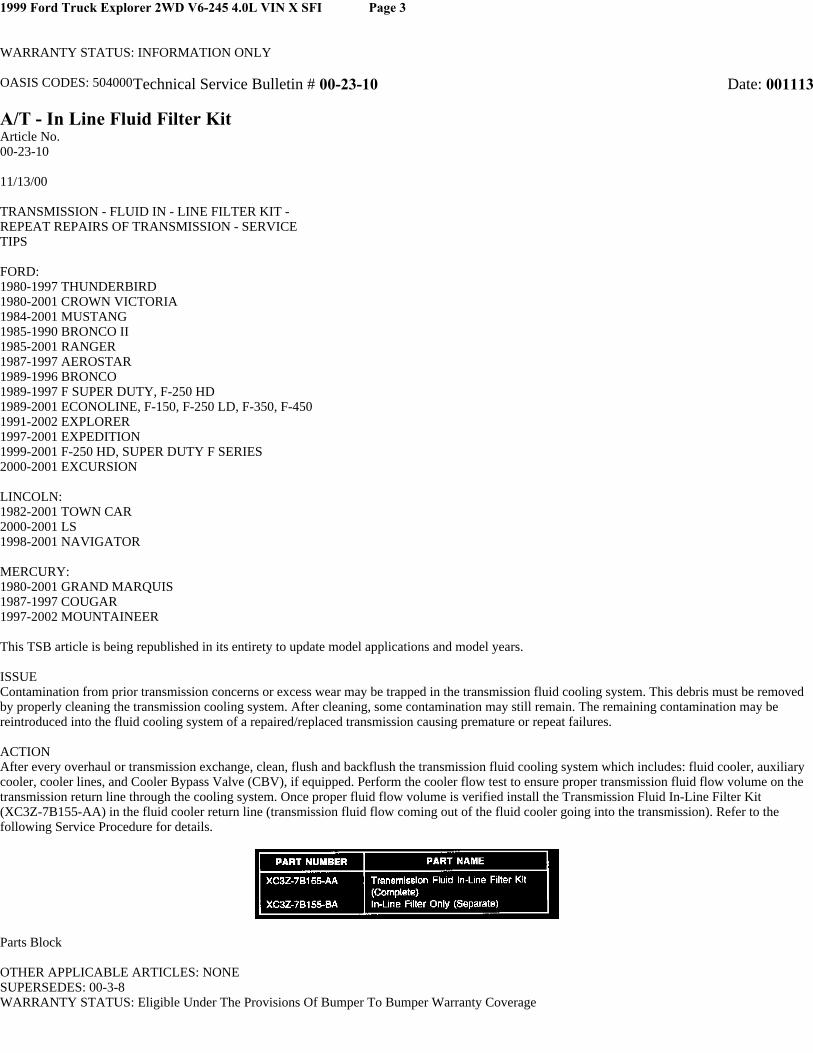
ACTIONAfter every overhaul or transmission exchange, clean, flush and backflush the transmission fluid cooling system which includes: fluid cooler, auxiliarycooler, cooler lines, and Cooler Bypass Valve (CBV), if equipped. Perform the cooler flow test to ensure proper transmission fluid flow volume on thetransmission return line through the cooling system. Once proper fluid flow volume is verified install the Transmission Fluid In-Line Filter Kit(XC3Z-7B155-AA) in the fluid cooler return line (transmission fluid flow coming out of the fluid cooler going into the transmission). Refer to thefollowing Service Procedure for details.
Parts Block
OTHER APPLICABLE ARTICLES: NONESUPERSEDES: 00-3-8WARRANTY STATUS: Eligible Under The Provisions Of Bumper To Bumper Warranty Coverage

1999 Ford Truck Explorer 2WD V6-245 4.0L VIN X SFI Page 4
OPERATION/DESCRIPTION/TIME
DEALER CODING
OASIS CODES: 501000, 502000, 503000, 504000, 507000, 510000, 590000, 597997
Service ProcedureNOTE
THIS IN-LINE TRANSMISSION FLUID FILTER KIT CAN BE INSTALLED ON ALL TRANSMISSIONS WITH 8 mm (5/16") AND 9.5 mm(3/8") TRANSMISSION FLUID COOLER LINES.
NOTETHIS IN-LINE TRANSMISSION FLUID FILTER KIT WILL ALSO BE SUPPLIED WITH ALL E40D/4R100 AND OTHER FORD QUALITYREMANUFACTURED (FOR) TRANSMISSIONS. AFTER ANY OVERHAUL OR TRANSMISSION EXCHANGE PRIOR TO CONNECTINGTHE TRANSMISSION FLUID COOLING SYSTEM TO THE TRANSMISSION, FOLLOW THE STEPS BELOW.
1. Clean, flush and backflush transmission fluid cooling system.
NOTEVEHICLES EQUIPPED WITH STAND-ALONE OIL-TO-AIR (OTA) FLUID COOLERS CANNOT BE PROPERLY FLUSHED.ADDITIONALLY, 1998-2001 CROWN VICTORIA/GRAND MARQUIS AND TOWN CAR HAVE OIL-TO-AIR (OTA) FLUID COOLERSEQUIPPED WITH A TERMINAL BY-PASS VALVE. FOR ALL VEHICLES EQUIPPED WITH STAND-ALONE OTA COOLERS, THE OTACOOLER MUST BE REPLACED ON EVERY OVERHAUL OR TRANSMISSION EXCHANGE. REFER TO THE APPROPRIATESERVICE/WORKSHOP MANUAL FOR PROCEDURE.
2. Once the fluid cooling system has been cleaned, flushed and backflushed, connect the cooler lines and perform the transmission fluid flow test toensure proper fluid flow. Refer to the appropriate Service/Workshop Manual for procedure.
3. If proper fluid flow volume is not obtained, refer to appropriate Service/Workshop Manual for repair procedure. The transmission fluid coolers,auxiliary cooler, OTA, cooler lines, CBV (if equipped), transmission fluid pump or internal filter may be restricted or damaged and requirereplacement.
CAUTIONFAILURE TO FOLLOW THE KIT INSTRUCTIONS MAY CAUSE INTERNAL TRANSMISSION ASSEMBLY DAMAGE AND REPEATREPAIRS.
4. Only after proper transmission fluid flow volume is present, install the Transmission Fluid In-Line Filter Kit (XC3Z-7B155-AA). Follow theinstructions provided with the kit.
5. Once the filter is installed:
a. With the transmission fluid return line disconnected from the transmission, verify fluid flow through the filter.
b. Once the fluid flow in-and-out of the filter is verified, connect the transmission fluid return line to the transmission. Check and adjustproper transmission fluid level to normal operating range at normal operating temperature and check for leaks, kinks and chafe points (referto the "Do's and Don'ts" chart in the kit instructions).
NOTETHE FILTER INCLUDED IN THIS KIT WILL ALSO BE AVAILABLE AS A SEPARATE PART (XC3Z-7B155-BA). IT IS RECOMMENDEDTHAT THIS IN-LINE FILTER BE CHANGED EVERY 48,000 KILOMETERS (30,000 MILES).Technical Service Bulletin # 99-5-3Date:
990322
A/T - Cold Fluid Level Checking

1999 Ford Truck Explorer 2WD V6-245 4.0L VIN X SFI Page 5
Article No.99-5-3
03/22/99
TRANSMISSION - CHECKING TRANSMISSION FLUIDLEVEL COLD - SERVICE TIP
FORD:1997 THUNDERBIRD1997-99 CONTOUR, CROWN VICTORIA, MUSTANG, TAURUS
LINCOLN-MERCURY:1997-98 MARK VIII1997-99 CONTINENTAL, GRAND MARQUIS, MYSTIQUE, SABLE,TOWN CAR1999 COUGAR
LIGHT TRUCK:1997-99 ECONOLINE, EXPEDITION, EXPLORER, F-150, F-250 LD, MOUNTAINEER, RANGER, WINDSTAR1998-99 NAVIGATOR1999 SUPER DUTY F SERIES
ISSUESome vehicles equipped with an automatic transmission/transaxle are being overfilled with transmission fluid after repairs and during the pre-deliveryinspection. Over-filling the transmission/transaxle with transmission fluid may cause transmission shift concerns and/or internal transmission/transaxledamage. The 1999 Pre-Delivery Inspection (PDI) Manual is being revised for clarity.
1999 Ford Truck Explorer 2WD V6-245 4.0L VIN X SFI Copyright © 2008, ALLDATA 9.90 Page 6
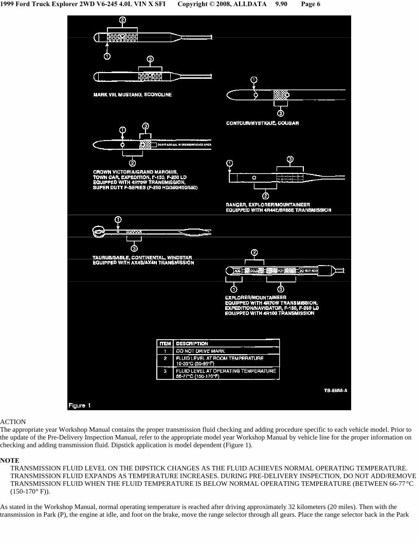
ACTIONThe appropriate year Workshop Manual contains the proper transmission fluid checking and adding procedure specific to each vehicle model. Prior tothe update of the Pre-Delivery Inspection Manual, refer to the appropriate model year Workshop Manual by vehicle line for the proper information onchecking and adding transmission fluid. Dipstick application is model dependent (Figure 1).
NOTETRANSMISSION FLUID LEVEL ON THE DIPSTICK CHANGES AS THE FLUID ACHIEVES NORMAL OPERATING TEMPERATURE.TRANSMISSION FLUID EXPANDS AS TEMPERATURE INCREASES. DURING PRE-DELIVERY INSPECTION, DO NOT ADD/REMOVETRANSMISSION FLUID WHEN THE FLUID TEMPERATURE IS BELOW NORMAL OPERATING TEMPERATURE (BETWEEN 66-77°C(150-170° F)).
As stated in the Workshop Manual, normal operating temperature is reached after driving approximately 32 kilometers (20 miles). Then with thetransmission in Park (P), the engine at idle, and foot on the brake, move the range selector through all gears. Place the range selector back in the Park

1999 Ford Truck Explorer 2WD V6-245 4.0L VIN X SFI Copyright © 2008, ALLDATA 9.90 Page 7
position, set the parking brake, and check fluid level.
Over-filling or under-filling transmission fluid may cause shift concerns and/or internal transmission/transaxle damage.
OTHER APPLICABLE ARTICLES: NONE WARRANTY STATUS: INFORMATION ONLY OASIS CODES: 504000, 510000, 590000Technical Service Bulletin # 99-11-1 Date: 990614
Comprehensive Noise/Vibration/Harshness ProcedureArticle No.99-11-1
06/14/99
^ NOISE - TSB SPECIAL FOR NOISE/VIBRATION/HARSHNESS
^ VIBRATION - TSB SPECIAL FOR NOISE/VIBRATION/HARSHNESS
FORD: 1995-1997 PROBE, THUNDERBIRD1995-1999 CONTOUR, CROWN VICTORIA, ESCORT, MUSTANG, TAURUS
LINCOLN-MERCURY:1995-1997 COUGAR1995-1998 MARK VIII1995-1999 CONTINENTAL, GRAND MARQUIS, MYSTIQUE, SABLE, TOWN CAR, TRACER1999 COUGAR2000 LS
LIGHT TRUCK: 1995-1997 F SUPER DUTY, F-250 HD, F-3501995-1999 ECONOLINE, EXPLORER, F-150, F-250 LD, RANGER, VILLAGER, WINDSTAR1997-1999 EXPEDITION, MOUNTAINEER1998-1999 NAVIGATOR1999 SUPER DUTY F SERIES
ISSUEThis TSB article is being published as a comprehensive Noise, Vibration and Harshness (NVH) diagnostic procedure. This procedure will also be in2000 model year and future Workshop Manuals in the NVH Section.
ACTIONUtilize the flowchart diagrams to work a problem from SYMPTOM to SYSTEM to COMPONENT to CAUSE. The tools and techniques section isexpanded to include ALL NVH diagnostic "tools". There are expanded SYMPTOM CHARTS to assist with problem resolution. A revised NVH courseis available through regional training centers. The course is "NVH Principals and Diagnostics", course code # 30s03t0. This course utilizes the sametechniques that are in the revised diagnostic procedure.
Refer to the Noise, Vibration and Harshness Work Shop Manual Section that is included.
OTHER APPLICABLE ARTICLES: NONE WARRANTY STATUS: INFORMATION ONLY OASIS CODES: 497000, 597997, 701000, 702000, 703000
SECTION 100-04 Noise, Vibration and Harshness VEHICLE APPLICATION: Noise, Vibration and Harshness
CONTENTS
DESCRIPTION AND OPERATION
Noise, Vibration and Harshness (NVH) Acceptable Noise, Vibration and Harshness
1999 Ford Truck Explorer 2WD V6-245 4.0L VIN X SFI Copyright © 2008, ALLDATA 9.90 Page 8
Diagnostic Theory Diagnostic Process Glossary of Terms Tools and Techniques
DIAGNOSIS AND TESTING
Noise, Vibration and Harshness (NVH) Component Tests Diagnostic Process
1: Customer Interview 2: Pre-Drive Check 3: Preparing for the Road Test 4: Verify the Customer Concern 5: Road Test 6: Check OASIS/TSBs/Repair History 7: Diagnostic Procedure
NVH Condition and Symptom Categories Pinpoint Tests Symptom Charts
GENERAL PROCEDURES
Exhaust System Neutralizing Powertrain/Drivetrain Mount Neutralizing Wheel Bearing Check
Noise, Vibration and Harshness (NVH)Noise is any undesirable sound, usually unpleasant in nature. Vibration is any motion, shaking or trembling, that can be felt or seen when an objectmoves back and forth or up and down. Harshness is a ride quality issue where the vehicle's response to the road transmits sharply to the customer.Harshness normally describes a firmer than usual response from the suspension system. Noise, vibration and harshness (NVH) is a term used todescribe these conditions, which customers sense and result in varying degrees of dissatisfaction. Although, a certain level of NVH caused by road andenvironmental conditions is normal. This section is designed to aid in the diagnosis, testing and repair of NVH concerns.
Acceptable Noise, Vibration and HarshnessAll internal combustion engines and drivelines produce some noise and vibration; operating in a real world environment adds noise that is not subject tocontrol. Vibration isolators, mufflers and dampers reduce these to acceptable levels. A driver who is unfamiliar with a vehicle can think that somesounds are abnormal when actually the sounds are normal for the vehicle type. For example, Traction-Lok(R) differentials produce a slight noise onslow turns after extended highway driving. This is acceptable and has no detrimental effect on the locking axle function. As a technician, it is veryimportant to be familiar with vehicle features and know how they relate to NVH concerns and their diagnosis. If, for example, the vehicle has automaticoverdrive it is important to test drive the vehicle both in and out of overdrive mode.
Diagnostic TheoryThe shortest route to an accurate diagnosis results from:
^ system knowledge, including comparison with a known good system.
^ system history, including repair history and usage patterns.
^ condition history, especially any relationship to repairs or sudden change.
^ knowledge of probable causes
^ using a systematic diagnostic method that divides the system into related areas.
The diagnosis and correction of noise, vibration and harshness concerns requires:
^ a road or system test to determine the exact nature of the concern.
^ an analysis of the possible causes.
^ testing to verify the cause.
^ repairing any concerns found.

1999 Ford Truck Explorer 2WD V6-245 4.0L VIN X SFI Copyright © 2008, ALLDATA 9.90 Page 9
^ a road test or system test to make sure the concern has been corrected or brought back to within a acceptable range.
Diagnostic ProcessA good diagnostic process is a logical sequence of steps that lead to the identification of a causal system. The following flowcharts are a graphicrepresentation of the diagnostic process. Use the flowcharts as follows:
^ Choose the appropriate flowchart.
^ Identify the operating condition that the vehicle is exhibiting.
^ Advance through the flowchart from left to right.
^ Match the operating condition to the symptom.
^ Verify the symptom.
^ Identify which category or system could cause the symptom.
^ Refer to the diagnostic symptom chart that the flowchart refers to.
Glossary of TermsAcceleration-LightAn increase in speed at less than half throttle.
Acceleration-MediumAn increase in speed at half to nearly full throttle, such as 0-97 km/h (0-60 mph) in approximately 30 seconds.
Acceleration-HeavyAn increase in speed at one-half to full throttle, such as 0-97 km/h (0-60 mph) in approximately 20 seconds.
Ambient TemperatureThe surrounding or prevailing temperature.
AmplitudeThe quantity or amount of energy produced by a vibrating component (G force). An extreme vibration has a high amplitude. A mild vibration has a lowamplitude.
BacklashGear teeth clearance.
BoomLow frequency or low pitched noise often accompanied by a vibration. Also refer to Drumming.
Bound UpAn overstressed isolation (rubber) mount that transmits vibration/noise instead of absorbing it.
Brakes AppliedWhen the service brakes are applied with enough force to hold the vehicle against movement with the transmission in gear.
Buffet/BuffetingStrong noise fluctuations caused by gusting winds. An example would be wind gusts against the side glass.
BuzzA low-pitched sound like that from a bee. Often a metallic or hard plastic humming sound. Also describes a high frequency (200-800 Hz) vibration.Vibration feels similar to an electric razor.
CamberThe angle of the wheel in relation to the true vertical as measured looking from the front of the vehicle. Camber is positive when the wheel angle isoffset so that the top of the wheel is positioned away from the vehicle.
CasterThe angle of the steering knuckle in relation to the true vertical as measured looking from the side of the vehicle.
ChatterA pronounced series of rapidly repeating rattling or clicking sounds.

1999 Ford Truck Explorer 2WD V6-245 4.0L VIN X SFI Copyright © 2008, ALLDATA 9.90 Page 10
ChirpA short-duration high-pitched noise associated with a slipping drive belt.
ChuckleA repetitious low-pitched sound. A loud chuckle is usually described as a knock.
ClickA sharp, brief, non-resonant sound, similar to actuating a ball point pen.
ClonkA hydraulic knocking sound. Sound occurs with air pockets in a hydraulic system. Also described as hammering.
Clunk/Driveline ClunkA heavy or dull, short-duration, low-frequency sound.Occurs mostly on a vehicle that is accelerating or decelerating abruptly. Also described as a thunk.
Coast/DecelerationReleasing the accelerator pedal at cruise, allowing the engine to reduce vehicle speed without applying the brakes.
Coast/Neutral CoastPlacing the transmission range selector in NEUTRAL (N) or depressing the clutch pedal while at cruise.
Constant Velocity (CV) JointA joint used to absorb vibrations caused by driving power being transmitted at an angle.
Controlled Rear Suspension HeightThe height at which a designated vehicle element must be when driveline angle measurements are made.
Coupling ShaftThe shaft between the transfer case and the front drive axle or, in a two-piece rear driveshaft, the front section.
CPSCycles per second. Same as hertz (Hz).
CracksA mid-frequency sound, related to squeak. Sound varies with temperature conditions.
CreakA metallic squeak.
CruiseConstant speed on level ground; neither accelerating nor decelerating.
CycleThe process of a vibrating component going through a complete range of motion and returning to the starting point.
DecibelA unit of measurement, referring to sound pressure level, abbreviated dB.
Drive Engine Run-Up (DERU) TestThe operation of the engine through the normal rpm range with the vehicle standing still, the brakes applied and the transmission engaged. This test isused for noise and vibration checks.
Driveline AnglesThe differences of alignment between the transmission output shaft, the drive shaft, and the rear axle pinion centerline.
DriveshaftThe shaft that transmits power to the rear axle input shaft (pinion shaft). In a two-piece driveshaft, it is the rearmost shaft.
DrivetrainAll power transmitting components from the engine to the wheels; includes the clutch or torque converter, the transmission, the transfer case, thedriveshaft, and the front or rear drive axle.
Drivetrain DamperA weight attached to the engine, the transmission, the transfer case, or the axle. It is tuned by weight and placement to absorb vibration.
1999 Ford Truck Explorer 2WD V6-245 4.0L VIN X SFI Copyright © 2008, ALLDATA 9.90 Page 11
DroneA low frequency (100-200 Hz) steady sound, like a freezer compressor. Also described as a moan.
DrummingA cycling, low-frequency (20-100 Hz), rhythmic noise often accompanied by a sensation of pressure on the eardrums. Also described as a low rumble,boom, or rolling thunder.
Dynamic BalanceThe equal distribution of weight on each side of the centerline, so that when the wheel and tire assembly spins, there is no tendency for the assembly tomove from side-to-side (wobble). Dynamically unbalanced wheel and tire assemblies can cause wheel shimmy.
Engine ImbalanceA condition in which an engine's center mass is not concentric to the rotation center. Excessive motion.
Engine MisfireWhen combustion in one or more cylinders does not occur or occurs at the wrong time.
Engine ShakeAn exaggerated engine movement or vibration that directly increases in frequency as the engine speed increases. It is caused by non-equal distributionof mass in the rotating or reciprocating components.
Flexible CouplingA flexible joint.
FloatA drive mode on the dividing line between cruise and coast where the throttle setting matches the engine speed with the road speed.
FlutterMid to high (100-200 Hz) intermittent sound due to air flow. Similar to a flag flapping in the wind.
FrequencyThe rate at which a cycle occurs within a given time.
Gravelly FeelA grinding or growl in a component, similar to the feel experienced when driving on gravel.
GrindAn abrasive sound, similar to using a grinding wheel, or rubbing sand paper against wood.
HissSteady high frequency (200-800 Hz) noise. Vacuum leak sound.
HootA steady low frequency tone (50-500 Hz), sounds like blowing over a long neck bottle.
HowlA mid-range frequency noise between drumming and whine.
HumMid-frequency (200-800 Hz) steady sound, like a small fan motor. Also described as a howl.
HzHertz; a frequency measured in cycles per second.
ImbalanceOut of balance; heavier on one side than the other. In a rotating component, imbalance often causes vibration.
InboardToward the centerline of the vehicle.
IntensityThe physical quality of sound that relates to the strength of the vibration (measured in decibels). The higher the sound's amplitude, the higher theintensity and vice versa.
Isolate

1999 Ford Truck Explorer 2WD V6-245 4.0L VIN X SFI Copyright © 2008, ALLDATA 9.90 Page 12
To separate the influence of one component to another.
KnockA heavy, loud, repetitious sound, like a knock on the door.
MoanA constant, low-frequency (100-200 Hz) tone. Also described as a hum.
Neutral Engine Run-Up (NERU) TestThe operation of the engine through the normal rpm range with the vehicle standing still and the transmission disengaged. This test is used to identifyengine related vibrations.
Neutralize/NormalizeTo return to an unstressed position. Used to describe mounts. Refer to Bound Up.
NVHNoise, vibration and harshness. A term used to describe conditions, which customers sense and result in varying degrees of dissatisfaction.
OutboardAway from the centerline of the vehicle.
PingA short duration, high-frequency sound, which has a slight echo.
Pinion ShaftThe input shaft in a driving axle that is usually a part of the smaller driving or input hypoid gear of a ring and pinion gearset.
PitchThe physical quality of sound that relates to its frequency. Pitch increases as frequency increases and vice versa.
Pumping FeelA slow, pulsing movement.
Radial/LateralRadial is in the plane of rotation; lateral is at 90 degrees to the plane of rotation.
RattleA random and momentary or short duration noise.
Ring GearThe large, circular, driven gear in a ring and pinion gearset.
Road TestThe operation of the vehicle under conditions intended to produce the concern under investigation.
RoughnessA medium-frequency vibration. A slightly higher frequency (20 to 50 Hz) than a shake. This type of vibration is usually related to drivetraincomponents.
RunoutOut of round and wobble.
1999 Ford Truck Explorer 2WD V6-245 4.0L VIN X SFI Copyright © 2008, ALLDATA 9.90 Page 13
RustlingIntermittent sound of varying frequency (100-200 Hz), sounds similar to shuffling through leaves.
ShakeA low-frequency vibration (5-20 Hz), usually with visible component movement. Usually relates to tires, wheels, brake drums or brake discs if it isvehicle speed sensitive, or engine if it is engine speed sensitive. Also referred to as a shimmy or wobble.
ShimmyAn abnormal vibration or wobbling, felt as a side-to-side motion of the steering wheel in the driveshaft rotation. Also described as waddle.
ShudderA low-frequency vibration that is felt through the steering wheel or seat during light brake application.
SlapA resonance from flat surfaces, such as safety belt webbing or door trim panels.
Slip Yoke/Slip SplineThe driveshaft coupling that allows length changes to occur while the suspension articulates and while the driveshaft rotates.
SqueakA high-pitched transient sound, similar to rubbing fingers against a clean window.
SquealA long-duration, high-pitched noise.
Static BalanceThe equal distribution of weight around the wheel. Statically unbalanced wheel and tire assemblies can cause a bouncing action called wheel tramp.This condition will eventually cause uneven tire wear.
TapA light, rhythmic, or intermittent hammering sound, similar to tapping a pencil on a table edge.
ThumpA dull beat caused by two items striking together.
TickA rhythmic tap, similar to a clock noise.
Tip-In MoanA light moaning noise heard during light vehicle acceleration, usually between 40-100 km/h (25-65 mph).
TIRTotal indicated run out
Tire DeflectionThe change in tire diameter in the area where the tire contacts the ground.
Tire Flat SpotsA condition commonly caused by letting the vehicle stand while the tires cool off. This condition can be corrected by driving the vehicle until the tiresare warm. Also, irregular tire wear patterns in the tire tread resulting from wheel-locked skids.
1999 Ford Truck Explorer 2WD V6-245 4.0L VIN X SFI Copyright © 2008, ALLDATA 9.90 Page 14
Tire Force VibrationA tire vibration caused by variations in the construction of the tire that is noticeable when the tire rotates against the pavement. This condition can bepresent on perfectly round tires because of variations in the inner tire construction. This condition can occur at wheel rotation frequency or twicerotation frequency.
TransientMomentary, short duration.
Two-Plane BalanceRadial and lateral balance.
VibrationAny motion, shaking or trembling, that can be felt or seen when an object moves back and forth or up and down.
WhineA constant, high-pitched noise. Also described as a screech.
WhistleHigh-pitched noise (above 500Hz) with a very narrow frequency band. Examples of whistle noises are a turbocharger or airflow around an antenna.
Wind NoiseAny noise caused by air movement in, out or around the vehicle.
WOTWide-open throttle
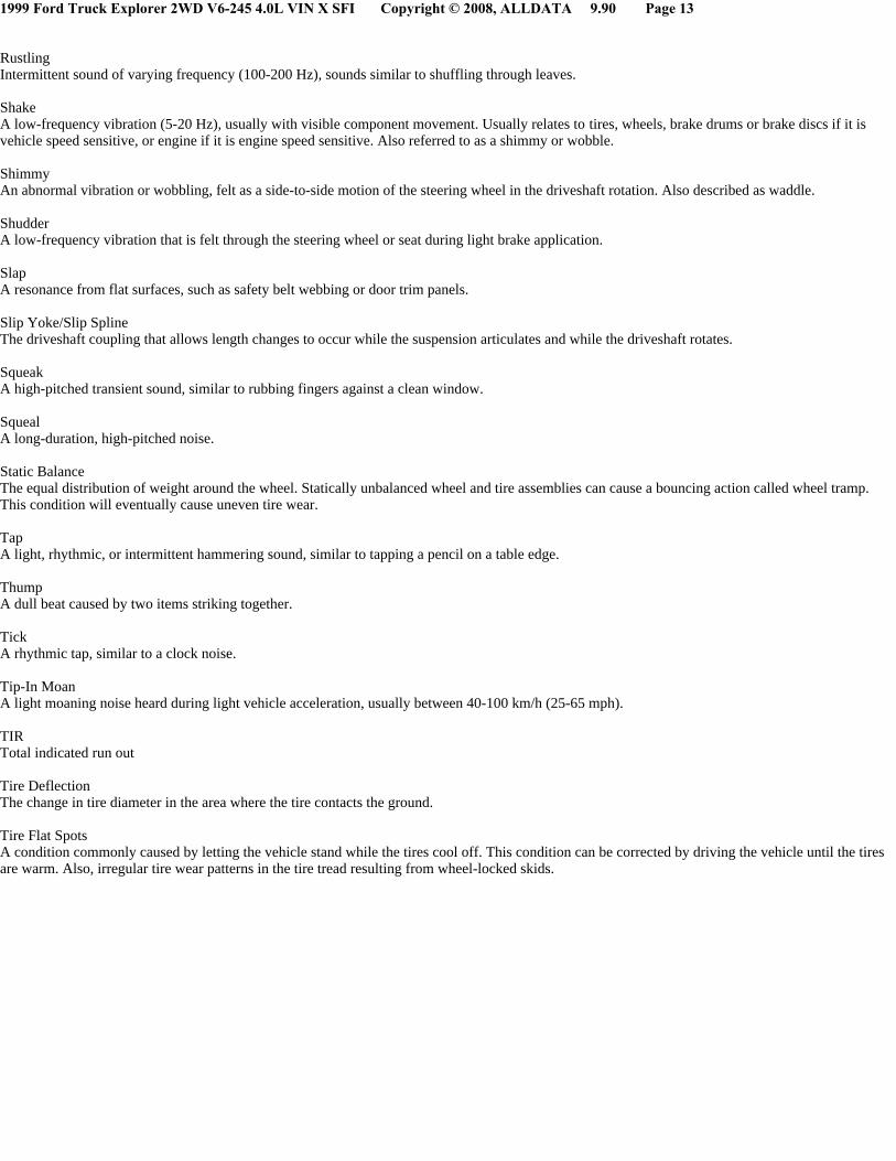
Tools and TechniquesElectronic Vibration Analyzer (EVA)
The EVA is a hand-held electronic diagnostic tool which will assist in locating the source of unacceptable vibrations. The vibration sensor can beremotely mounted anywhere in the vehicle for testing purposes. The unit displays the three most common vibration frequencies and their correspondingamplitudes simultaneously. A bar graph provides a visual reference of the relative signal strength (amplitude) of each vibration being displayed and itsrelative G force. The keypad is arranged to make the EVA simple to program and use. Some of the functions include the ability to average readings aswell as record, play back and freeze readings. The EVA has a strobe balancing function that can be used to detect imbalance on rotating componentssuch as a driveshaft or engine accessories.
1999 Ford Truck Explorer 2WD V6-245 4.0L VIN X SFI Copyright © 2008, ALLDATA 9.90 Page 15
The EVA allows for a systematic collection of information that is necessary to accurately diagnose and repair NVH problems. For the best results, carryout the test as follows:
a. Test drive the vehicle with the vibration sensorinside the vehicle.
b. Place the sensor in the vehicle according to feel.
- If the condition is felt through the steeringwheel, the source is most likely in the front ofthe vehicle.
- A vibration that is felt in the seat or floor onlywill most likely be found in the driveline,drive axle or rear wheels and tires.
c. Record the readings. Also note when the condition begins when it reaches maximum intensity. and if it tends to diminish above/below a certainspeed.
- Frequencies should be read in the "avg" mode.
- Frequencies have a range of plus or minus 2. A reading of 10 Hz can be displayed as an 8 Hz through 12 Hz.
d. Determine what the normal frequency is for the vehicle at a specified speed. Multiply the rear axle ratio by the Hz (1 Hz per every 5 mph).Example: A vehicle travelling 50 mph with a 3.08 rear axle ratio, the acceptable amount of Hz for the vehicle at that speed would be 10 (1 Hz perevery 5 mph) X 3.08 (rear axle ratio) = 30.8 Hz.
e. Place the vibration sensor on or near the suspect area outside the vehicle.
f. Continue the road test, driving the vehicle at the speed the symptom occurs, and take another reading.
1999 Ford Truck Explorer 2WD V6-245 4.0L VIN X SFI Copyright © 2008, ALLDATA 9.90 Page 16
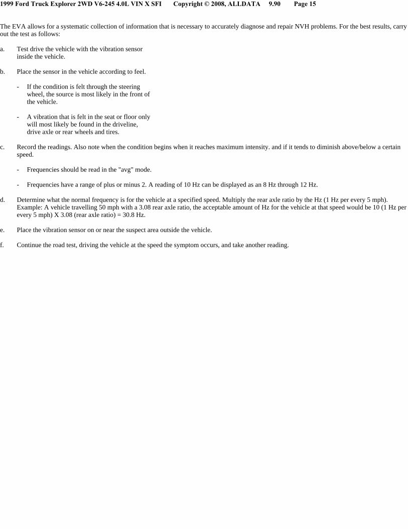
g. Compare the readings.
- A match in frequency indicates the problem component or area.
- An unmatched test could indicate the concern is caused by the engine, torque converter, or engine accessory. Use the EVA in the rpm modeand check if concern is rpm related.
- Example: A vibration is felt in the seat, place the sensor on the console. Record the readings. Place the vibration sensor on the rear axle.Compare the readings. If the frequencies are the same, the axle is the problem component. Also refer to the following chart as a reference toacceptable vibration and noise ranges for the specified components.
Vibrate Software(R)
Vibrate software(R) (Rotunda tool number 215-00003) is a diagnostic aid which will assist in pinpointing the source of unacceptable vibrations. The

1999 Ford Truck Explorer 2WD V6-245 4.0L VIN X SFI Copyright © 2008, ALLDATA 9.90 Page 17
engine's crankshaft is the point of reference for vibration diagnosis. Every rotating component will have an angular velocity that is faster, slower, or thesame as the engine's crankshaft. Vibrate software® calculates the angular velocity of each component and graphically represents these velocities on acomputer screen and on a printed vibration worksheet. The following steps outline how Vibrate software® helps diagnose a vibration concern:
^ Enter the vehicle information. Vibrate will do all the calculations and display a graph showing tire, driveshaft and engine vibrations.
^ Print a Vibration Worksheet graph. The printed graph is to be used during the road test.
^ Road test the vehicle at the speed where the vibration is most noticeable. Record the vibration frequency (rpm) and the engine rpm on the worksheetgraph. The point on the graph where the vibration frequency (rpm) reading and the engine rpm reading intersect indicates the specific componentgroup causing the concern.
- An EVA or equivalent tool capable of measuring vibration frequency and engine rpm will be needed.
^ Provides pictures of diagnostic procedures to aid in testing components.
ChassisEAR
An electronic listening device used to quickly identify noise and the location under the chassis while the vehicle is being road tested. The chassisEARscan identify the noise and location of damaged/worn wheel bearings, CV joints, brakes, springs, axle bearings or driveshaft carrier bearings.
EngineEAR
An electronic listening device used to detect even the faintest noises. The EngineEARs can detect the noise of damaged/worn bearings in generators,water pumps, A/C compressors and power steering pumps. They are also used to identify noisy lifters, exhaust manifold leaks, chipped gear teeth andfor detecting wind noise. The EngineEAR has a sensing tip, amplifier, and headphones. The directional sensing tip is used to listen to the variouscomponents. Point the sensing tip at the suspect component and adjust the volume with the amplifier. Placing the tip in direct contact with a componentwill reveal structure-borne noise and vibrations, generated by or passing through, the component. Various volume levels can reveal different sounds.
Ultrasonic Leak Detector
The Ultrasonic Leak Detector is used to detect wind noises caused by leaks and gaps in areas where there is weather-stripping or other sealing material.It is also used to identify A/C leaks, vacuum leaks and evaporative emission noises. The Ultrasonic Leak Detector includes a multi-directionaltransmitter (operating in the ultrasonic range) and a hand-held detector. The transmitter is placed inside the vehicle. On the outside of the vehicle, thehand-held detector is used to sweep the area of the suspected leak. As the source of the leak is approached, a beeping sound is produced which increasesin both speed and frequency.
Squeak and Rattle Repair Kit
The squeak and rattle repair kit contains lubricants and self-adhesive materials that can be used to eliminate interior and exterior squeaks and rattles.The kit consists of the following materials:
^ PVC (soft foam) tape
^ Urethane (hard foam) tape
^ Flocked (black fuzzy) tape
^ UHMW (frosted) tape
^ Squeak and rattle oil tube
1999 Ford Truck Explorer 2WD V6-245 4.0L VIN X SFI Copyright © 2008, ALLDATA 9.90 Page 18
^ Squeak and rattle grease tube
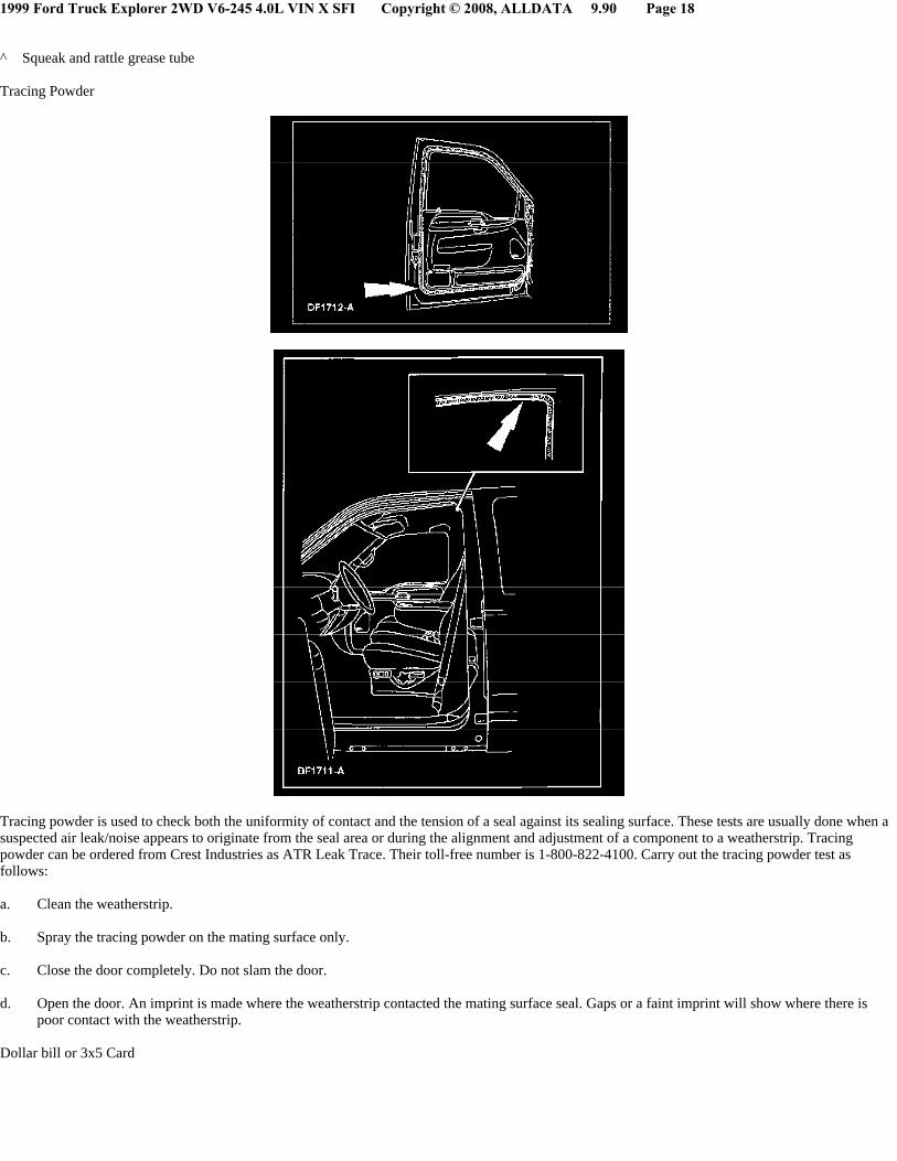
Tracing Powder
Tracing powder is used to check both the uniformity of contact and the tension of a seal against its sealing surface. These tests are usually done when asuspected air leak/noise appears to originate from the seal area or during the alignment and adjustment of a component to a weatherstrip. Tracingpowder can be ordered from Crest Industries as ATR Leak Trace. Their toll-free number is 1-800-822-4100. Carry out the tracing powder test asfollows:
a. Clean the weatherstrip.
b. Spray the tracing powder on the mating surface only.
c. Close the door completely. Do not slam the door.
d. Open the door. An imprint is made where the weatherstrip contacted the mating surface seal. Gaps or a faint imprint will show where there ispoor contact with the weatherstrip.
Dollar bill or 3x5 Card

1999 Ford Truck Explorer 2WD V6-245 4.0L VIN X SFI Copyright © 2008, ALLDATA 9.90 Page 19
Place a dollar bill or 3x5 card between the weatherstrip and the sealing surface, then close the door. Slowly withdraw the bill or 3x5 card after the dooris closed and check the amount of pressure on the weatherstrip. There should be a medium amount of resistance as the dollar bill or 3x5 card iswithdrawn. Continue around the entire seal area. If there is little or no resistance, this indicates insufficient contact to form a good seal. At these points,the door, the glass, or the weatherstrip is out of alignment.
Diagnosis and TestingNoise, Vibration and Harshness (NVH)
Special Service Tool(s)
Diagnostic Process

1999 Ford Truck Explorer 2WD V6-245 4.0L VIN X SFI Copyright © 2008, ALLDATA 9.90 Page 20
1999 Ford Truck Explorer 2WD V6-245 4.0L VIN X SFI Copyright © 2008, ALLDATA 9.90 Page 21

1999 Ford Truck Explorer 2WD V6-245 4.0L VIN X SFI Copyright © 2008, ALLDATA 9.90 Page 22
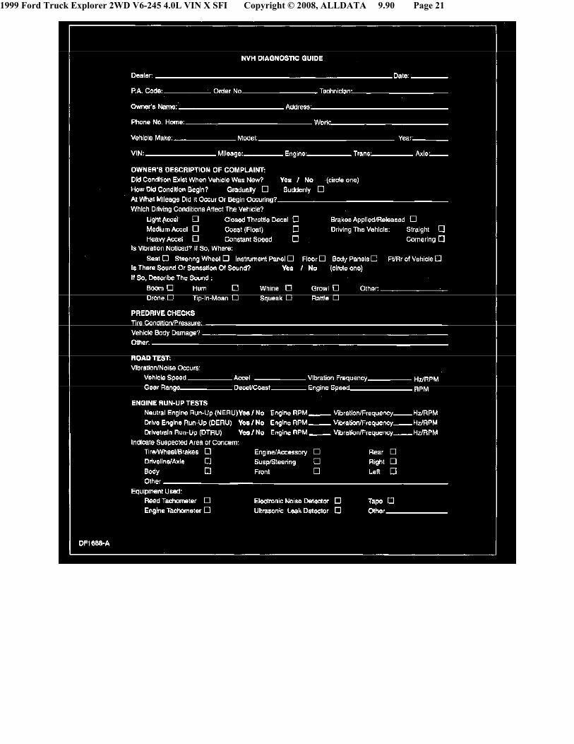
To assist the service advisor and the technician, a Write-up Job Aid and an NVH Diagnostic Guide are included with this material. The Write-up JobAid serves as a place to record all important symptom information. The NVH Diagnostic Guide serves as a place to record information reported on theWrite-up Job Aid as well as data from the testing to be carried out.
To begin a successful diagnosis, fill out the NVH Diagnostic Guide, record the reported findings, then proceed to each of the numbered process steps tocomplete the diagnosis.
1. Customer InterviewThe diagnostic process starts with the customer interview. The service advisor must obtain as much information as possible about the problem and takea test drive with the customer. There are many ways a customer will describe NVH concerns and this will help minimize confusion arising fromdescriptive language differences. It is important that the concern is correctly interpreted and the customer descriptions are recorded. During theinterview, ask the following questions:

1999 Ford Truck Explorer 2WD V6-245 4.0L VIN X SFI Copyright © 2008, ALLDATA 9.90 Page 23
^ When was it first noticed?
^ Did it appear suddenly or gradually?
^ Did any abnormal occurrence coincide with or proceed it's appearance?
Use the information gained from the customer to accurately begin the diagnostic process.
2. Pre-Drive CheckIt is important to do a pre-drive check before road testing the vehicle. A pre-drive check verifies that the vehicle is relatively safe to drive andeliminates any obvious faults on the vehicle.
The pre-drive check consists of a brief visual inspection. During this brief inspection, take note of anything that will compromise safety during the roadtest and make those repairs/adjustments before taking the vehicle on the road.
3. Preparing For the Road TestObserve the following when preparing for the road test:
^ Review the information recorded on the NVH Diagnostic Guide. It is important to know the specific concern the customer has with the vehicle.
^ Do not be misled by the reported location of the noise/vibration. The cause can actually be some distance away.
^ Remember that the vibrating source component (originator) may only generate a small vibration. This small vibration can in turn cause a largervibration/noise to emanate from another receiving component (reactor), due to contact with other components (transfer path).
^ Conduct the road test on a quiet street where it is safe to duplicate the vibration/noise. The ideal testing route is an open, low-traffic area where it ispossible to operate the vehicle at the speed in which the condition occurs.
^ If possible, lower the radio antenna in order to minimize turbulence. Identify anything that could potentially make noise or be a source of windnoise. Inspect the vehicle for add-on items that create vibration/noise. Turn off the radio and the heating and cooling system blower.
^ The engine speed is an important factor in arriving at a final conclusion. Therefore, connect an accurate tachometer to the engine, even if the vehiclehas a tachometer. Use a tachometer that has clearly defined increments of less than 50 rpm. This ensures an exact engine speed reading.
4. Verify the Customer ConcernVerify the customer concern by carrying out a road test, an engine run-up test, or both.
The decision to carry out a road test, an engine run-up test, or both depends on the type of NVH concern. A road test may be necessary if the symptomrelates to the suspension system or is sensitive to torque. A drive engine run-up (DERU) or a neutral engine run-up (NERU) test identifies noises andvibrations relating to engine and drivetrain rpm. Remember, a condition will not always be identifiable by carrying out these tests, however, they willeliminate many possibilities if carried out correctly.
5. Road TestNote:
It may be necessary to have the customer ride along or drive the vehicle to point out the concern. During the road test. take into consideration thecustomer's driving habits and the driving conditions. The customer's concern just may be an acceptable operating condition for that vehicle.
The following is a brief overview of each test in the order in which it appears. A review of this information helps to quickly identify the mostappropriate process necessary to make a successful diagnosis. After reviewing this information, select and carry out the appropriate test(s), proceedingto the next step of this process.
^ The Slow Acceleration Test is normally the first test to carry out when identifying an NVH concern, especially when a road test with the customer isnot possible.
^ The Heavy Acceleration Test helps to determine if the concern is torque-related.
^ The Neutral Coast Down Speed Test helps to determine if the concern is vehicle speed-related.
^ The Downshift Speed Test helps to determine if the concern is engine speed-related.
^ The Steering Input Test helps to determine how the wheel bearings and other suspension components contribute to a vehicle speed-related concern.
^ The Brake Test helps to identify vibrations or noise that are brake related.
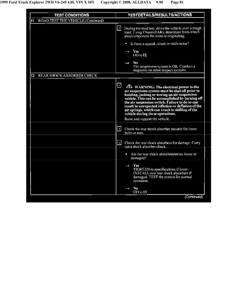
^ The Road Test Over Bumps helps isolate a noise that occurs when driving over a rough or bumpy surface.
^ The Engine Run-Up Tests consist of the Neutral Run-up Test and the Engine Load Test. These tests help to determine if the concern is engine
1999 Ford Truck Explorer 2WD V6-245 4.0L VIN X SFI Copyright © 2008, ALLDATA 9.90 Page 24
speed-related.
^ The Neutral Run-up Test is used as a follow-up test to the Downshift Speed Test when the concern occurs at idle.
^ The Engine Load Test helps to identify vibration/noise sensitive to engine load or torque. It also helps to reproduce engine speed-related concernsthat cannot be duplicated when carrying out the Neutral Run-up Test or the Neutral Coast Down Test.
^ The Engine Accessory Test helps to locate faulty belts and accessories that cause engine speed-related concerns.
^ The Vehicle Cold Soak Procedure helps to identify concerns occurring during initial start-up and when an extended time lapse occurs betweenvehicle usage.
Slow Acceleration Test
To carry out this test, proceed as follows:
^ Slowly accelerate to the speed where the reported concern occurs. Note the vehicle speed, the engine rpm and, if possible, determine the vibrationfrequency.
^ Attempt to identify from what part of the vehicle the concern is coming.
^ Attempt to identify the source of the concern.
^ Proceed as necessary.
Heavy Acceleration Test
To carry out this test, proceed as follows:
^ Accelerate hard from 0-64 km/h (0-40 mph).
^ Decelerate in a lower gear.
^ The concern is torque related if duplicated while carrying out this test.
^ Proceed as necessary.
Neutral Coast Down Speed Test
To carry out this test, proceed as follows:
^ Drive at a higher rate of speed than where the concern occurred when carrying out the Slow Acceleration Test.
^ Place the transmission in NEUTRAL and coast down past the speed where the concern occurs.
^ The concern is vehicle speed-related if duplicated while carrying out this test. This eliminates the engine and the torque converter as sources.
^ If the concern was not duplicated while carrying out this test, carry out the Downshift Speed Test to verify if the concern is engine speed related.
^ Proceed as necessary.
Downshift Speed Test
To carry out this test, proceed as follows:
^ Shift into a lower gear than the gear used when carrying out the Slow Acceleration Test.
^ Drive at the engine rpm where the concern occurs.
^ The concern is engine speed related if duplicated while carrying out this test. This eliminates the tires, wheels, brakes and the suspensioncomponents as sources.
^ If necessary, repeat this test using other gears and NEUTRAL to verify the results.
^ Proceed as necessary.

1999 Ford Truck Explorer 2WD V6-245 4.0L VIN X SFI Copyright © 2008, ALLDATA 9.90 Page 25
Steering Input Test
To carry out this test, proceed as follows:
^ Drive at the speed where the concern occurs, while making sweeping turns in both directions.
^ If the concern goes away or gets worse, the wheel bearings, hubs, U-joints (contained in the axles of 4WD applications), and tire tread wear are allpossible sources.
^ Proceed as necessary.
Brake Test
To carry out this test, proceed as follows:
^ Warm the brakes by slowing the vehicle a few times from 80-32 km/h (50-20 mph) using light braking applications. At highway speeds of 89-97km/h (50-60 mph), apply the brake using a light pedal force.
^ Accelerate to 89-97 km/h (55-60 mph).
^ Lightly apply the brakes and slow the vehicle to 30 km/h (20 mph).
^ A brake vibration noise can be felt in the steering wheel, seat or brake pedal. A brake noise can be heard upon brake application and diminish whenthe brake is release.
Road Test Over Bumps
To carry out this test, proceed as follows:
^ Drive the vehicle over a bump or rough surface one wheel at a time to determine if the noise is coming from the front or the back and the left or theright side of the vehicle.
^ Proceed as necessary.
Neutral Engine Run-up (NERU) Test
To carry out this test, proceed as follows:
^ In stall a tachometer.
^ Increase the engine rpm up from an idle to approximately 4000 rpm while in PARK on front wheel drive vehicles with automatic transmissions, orNEUTRAL for all other vehicles. Note the engine rpm and, if possible, determine the vibration frequency.
^ Attempt to identify what part of the vehicle the concern is coming from.
^ Attempt to identify the source of the concern.
^ Proceed as necessary.
Drive Engine Run-up (DERU) Load Test
To carry out this test, proceed as follows:
^ WARNING: Block the front and rear wheels, and apply the parking brake and the service brake, or injury to personnel can result.
^ CAUTION:Do not carry out the Engine Load Test for more than five seconds or damage to the transmission or transaxle can result.
Block the front and rear wheels.
^ Apply the parking brake and the service brake.
^ Install a tachometer.

1999 Ford Truck Explorer 2WD V6-245 4.0L VIN X SFI Copyright © 2008, ALLDATA 9.90 Page 26
^ Shift the transmission into DRIVE, and increase and decrease the engine rpm between an idle to approximately 2000 rpm. Note the engine rpm and,if possible, determine the vibration frequency.
^ Repeat the test in REVERSE.
^ If the vibration/noise is duplicated when carrying out this test, inspect the engine and transmission or transaxle mounts.
^ If the concern is definitely engine speed-related, carry out the Engine Accessory Test to narrow down the source.
^ Proceed as necessary.
Engine Accessory Test
To carry out this test, proceed as follows:
WARNING:Block the front and rear wheels, and apply the parking brake and the service brake, or injury to personnel can result.
CAUTION:Limit engine running time to one minute or less with belts removed or serious engine damage will result.
Note:A serpentine drive belt decreases the usefulness of this test. In these cases. use a vibration analyzer, such as the EVA, to pinpoint accessoryvibrations. An electronic listening device. such as an EngineEAR, will also help to identify noises from specific accessories.
Remove the accessory drive belts.
^ Increase the engine mm to where the concern occurs.
^ If the vibration/noise is duplicated when carrying out this test. the belts and accessories are not sources.
^ If the vibration/noise was not duplicated when carrying out this test, install each accessory belt, one at a time, to locate the source.
Vehicle Cold Soak Procedure
To carry out this procedure, proceed as follows:
^ Test preparations include matching customer conditions (if known). If not known, document the test conditions: gear selection and engine rpm.Monitor the vibration/noise duration with a watch for up to three minutes.
^ Park the vehicle where testing will occur. The vehicle must remain at or below the concern temperature (if known) for 6-~ hours.
^ Before starting the engine, conduct a visual inspection under the hood.
^ Turn the key on. but do not start the engine. Listen for the fuel pump. anti-lock brake system (ABS) and air suspension system noises.
^ Start the engine.
^ CAUTION: Never probe moving parts.
Isolate the vibration/noise by carefully listening. Move around the vehicle while listening to find the general location of the vibration/noise. Then,search for a more precise location by using a stethoscope or EngineEAR.
^ Refer to Idle Noise/Vibration in the Symptom Chart to assist with the diagnosis.
6. Check OASIS/TSBs/Repair HistoryAfter verifying the customer concern, check for OASIS reports, TSBs and the vehicle repair history for related concerns. If information relating to adiagnosis/repair is found, carry out the procedure(s) specified in that information.
If no information is available from these sources, carry out the vehicle preliminary inspection to eliminate any obvious faults.
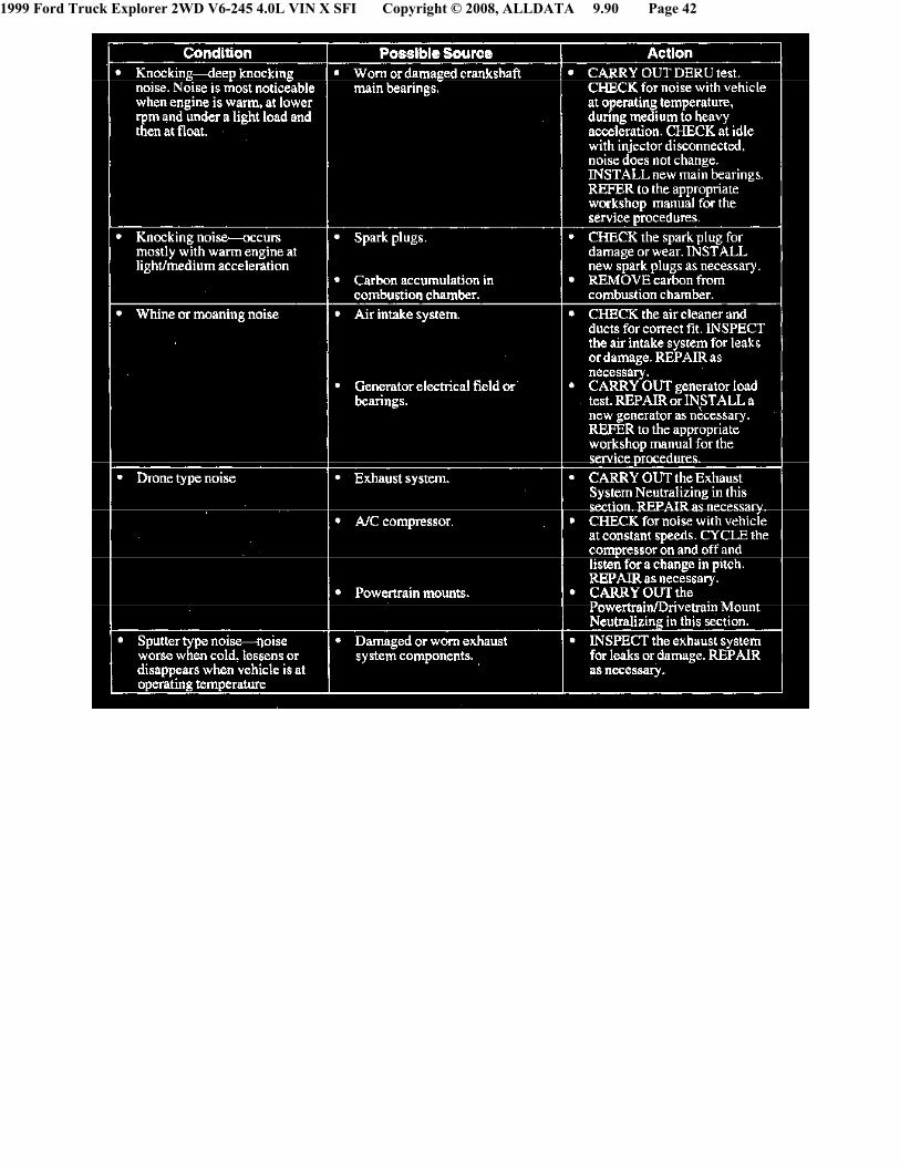
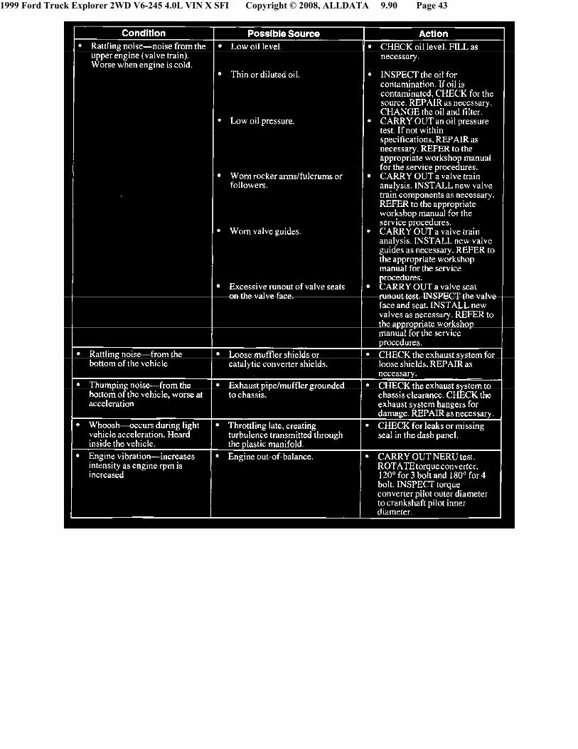
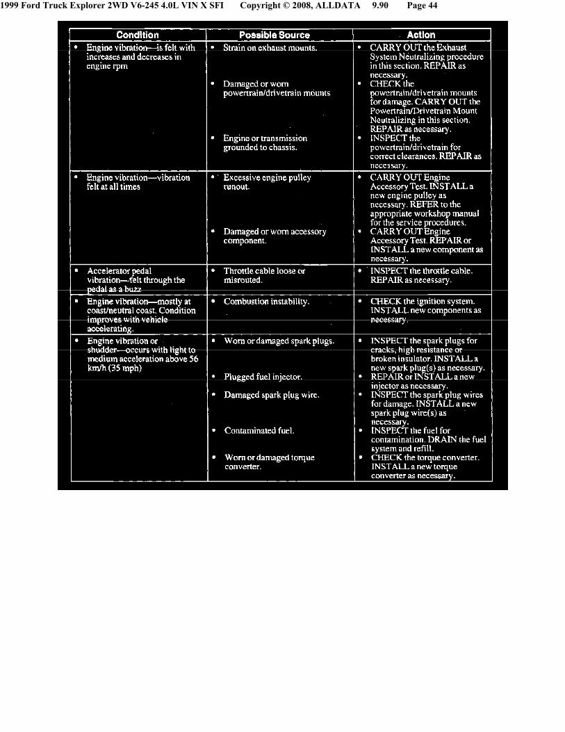
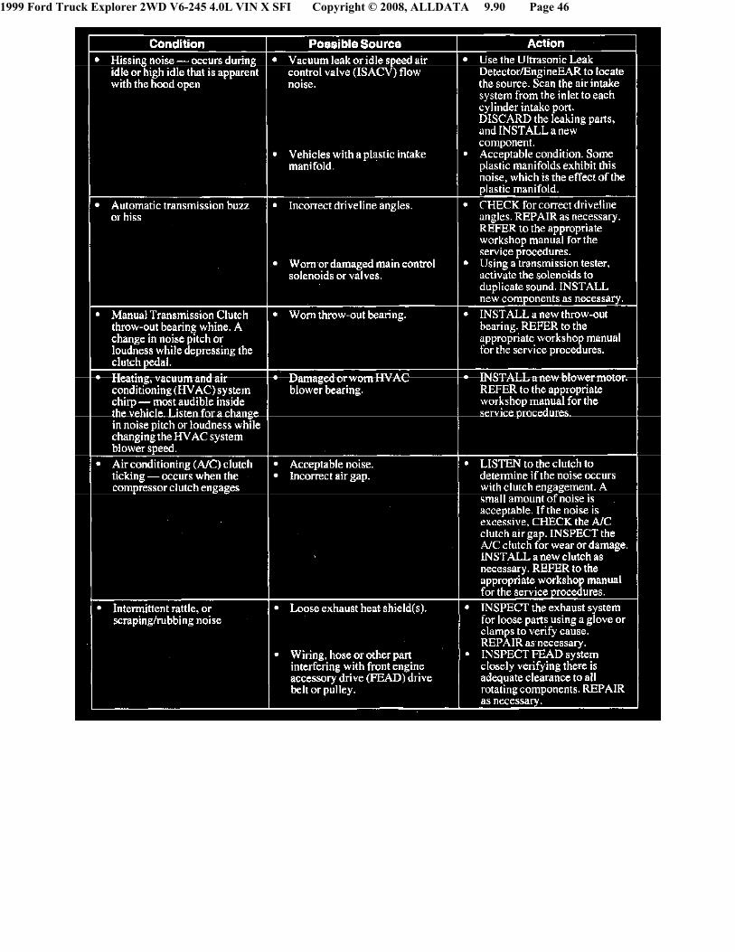
7. Diagnostic ProcedureQualifying the concern by the particular sensation present can help narrow down the concern. Always use the "symptom" to "system" to "component" to"cause" diagnosis technique. This diagnostic method divides the problem into related areas to correct the customer concern.

1999 Ford Truck Explorer 2WD V6-245 4.0L VIN X SFI Copyright © 2008, ALLDATA 9.90 Page 27
^ Verify the "symptom".
^ Determine which "system(s)" can cause the "symptom".
- If a vibration concern is vehicle speed related. the tire and wheel rpm/frequency or driveshaft frequency should be calculated.
- If a vibration concern is engine speed related. the engine, engine accessory or engine firing frequencies should be calculated.
^ After determining the "system", use the diagnostic tools to identify the worn or damaged 'components".
^ After identifying the "components". try to find the "cause" of the failure.
Once the concern is narrowed down to a symptom/condition. proceed to NVH Condition and Symptom Categories.
Operating Condition - Vehicle Is Not Moving1. Static operation
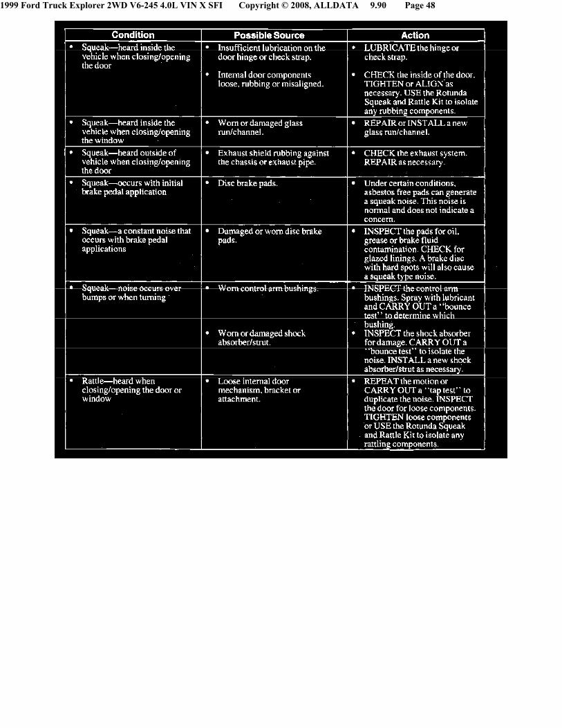
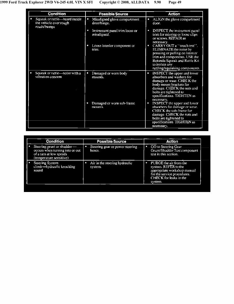
^ Noise occurs during part/system functioning.GO to Symptom Chart - Squeak and Rattle.
2. While cranking
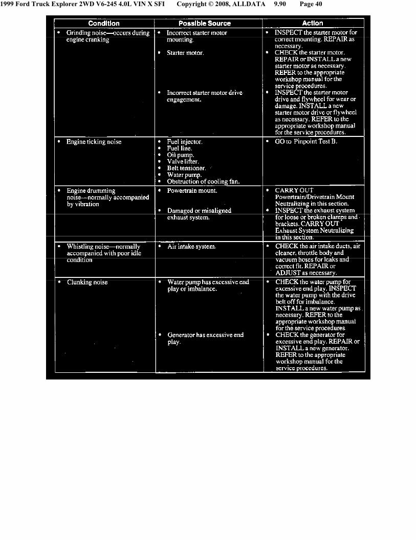
1. Grinding or whine, differential ring gear or starter motor pinion noise. GO to Symptom Chart - Engine Noise/Vibration.
2. Rattle. Exhaust hanger, exhaust heat shield or A/C line noise. GO to Symptom Chart - Squeak and Rattle.
3. Vibration. Acceptable condition.
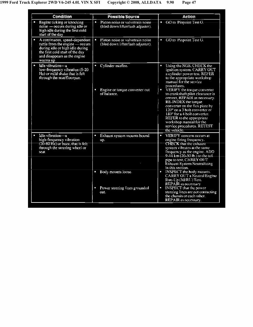
3. At idle
^ Idle noise. GO to Symptom Chart - IdleNoise/Vibration.
^ Idle vibration or shake. GO to SymptomChart - Idle Noise/Vibration.
4. During Gear Selection
1. Vehicle parked on a steep incline. Acceptablenoise.
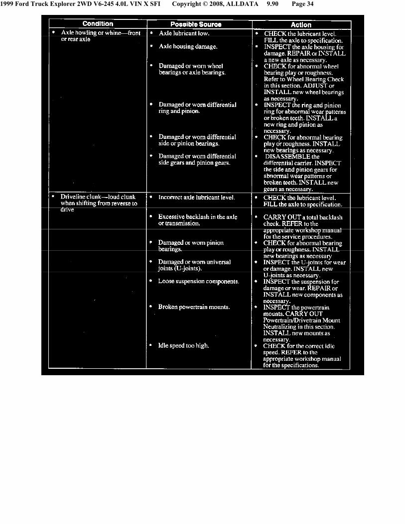
2. Vehicle parked on a flat surface. GO to Symptom Chart - Driveline Noise/Vibration.
3. Vehicle with a manual transmission. GO to Symptom Chart - Transmission (Manual) and Transfer Case Noise/Vibration.
Operating Condition - Vehicle Is Moving1. Depends more on how the vehicle is operated
1. Speed related
^ Related to vehicle speed
- Pitch increases with vehicle speed. GOto Symptom Chart - TireNoise/Vibration.
- Noise occurs at specific vehicle speed.A high-pitch noise (whine). GO toSymptom Chart - DrivelineNoise/Vibration.
- Loudness proportional to vehiclespeed. Low-frequency noise at highspeeds, noise and loudness increasewith speed. GO to Symptom Chart -Driveline Noise/Vibration.
1999 Ford Truck Explorer 2WD V6-245 4.0L VIN X SFI Copyright © 2008, ALLDATA 9.90 Page 28
- A low-pitched noise (drumming). GOto Symptom Chart - EngineNoise/Vibration.
- Vibration occurs at a particular speed(mph) regardless of acceleration ordeceleration. GO to Symptom Chart- Tire Noise/Vibration.
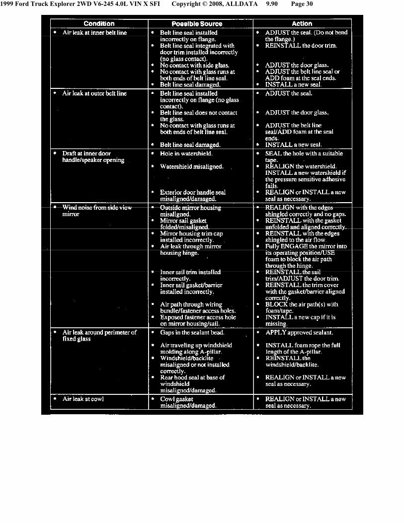
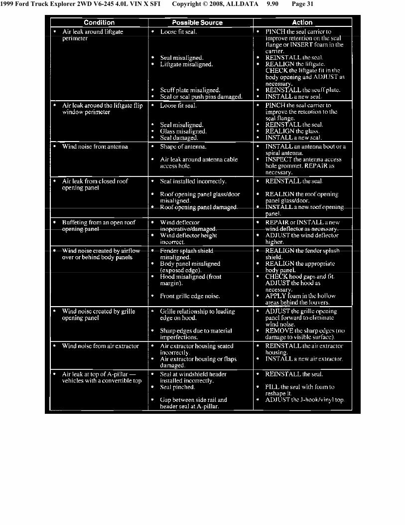
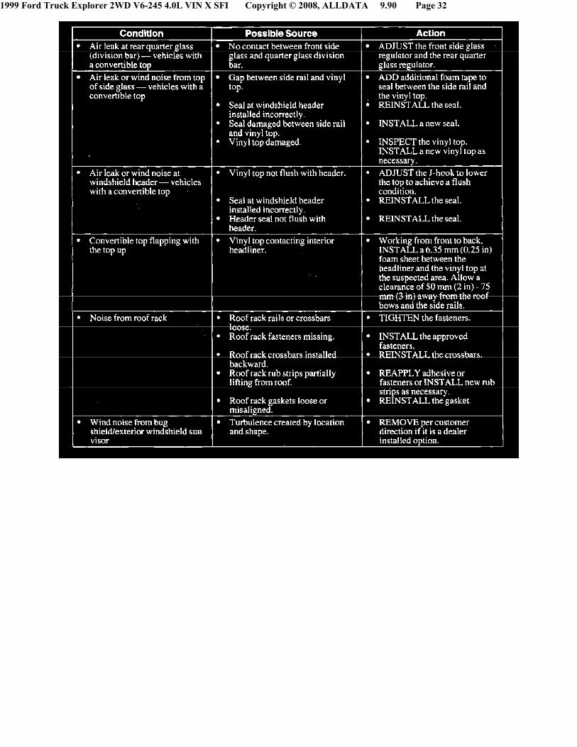
- Noise varies with wind/vehicle speedand direction. GO to Symptom Chart- Air Leak and Wind Noise.
^ Related to engine speed.
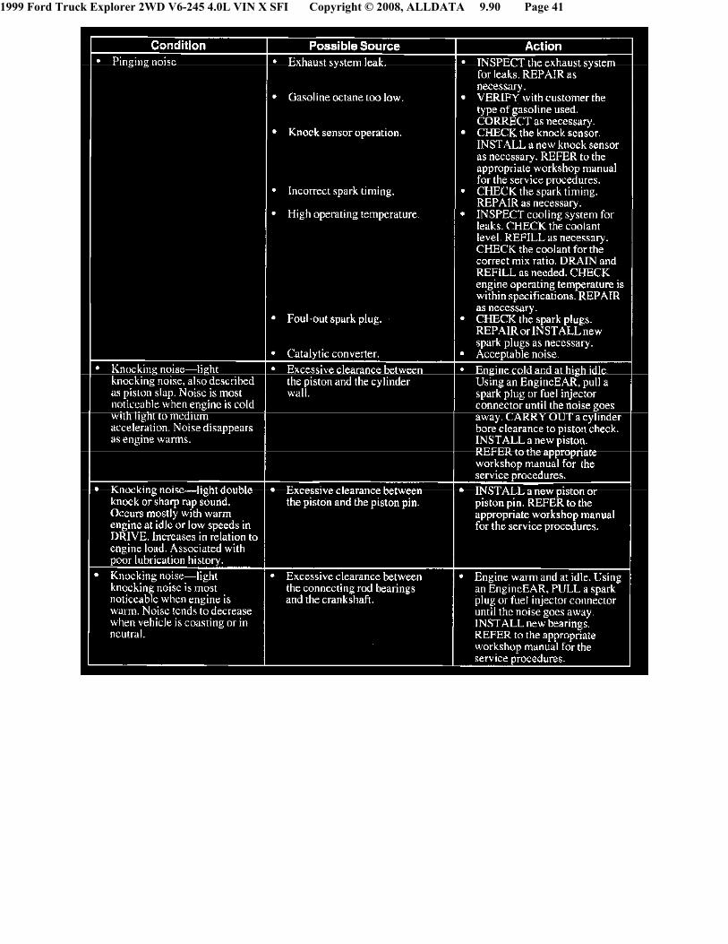
- Noise varies with engine rpm. GO to Symptom Chart - Engine Noise/Vibration.
- Vibration occurs at a particular speed (mph) regardless of engine speed (rpm).
2. Acceleration
^ Wide open throttle (WOT)
- Engine induced contact between components. Inspect and repair as necessary.
- Noise is continuous throughout WOT.Exhaust system or engine ground out.GO to Symptom Chart - EngineNoise/Vibration.
^ Light/moderate acceleration
- Tip-in moan. Engine/exhaust noise. GO to Symptom Chart - Engine Noise/Vibration.
- Knock-type noise. GO to Symptom Chart - Engine Noise/Vibration.
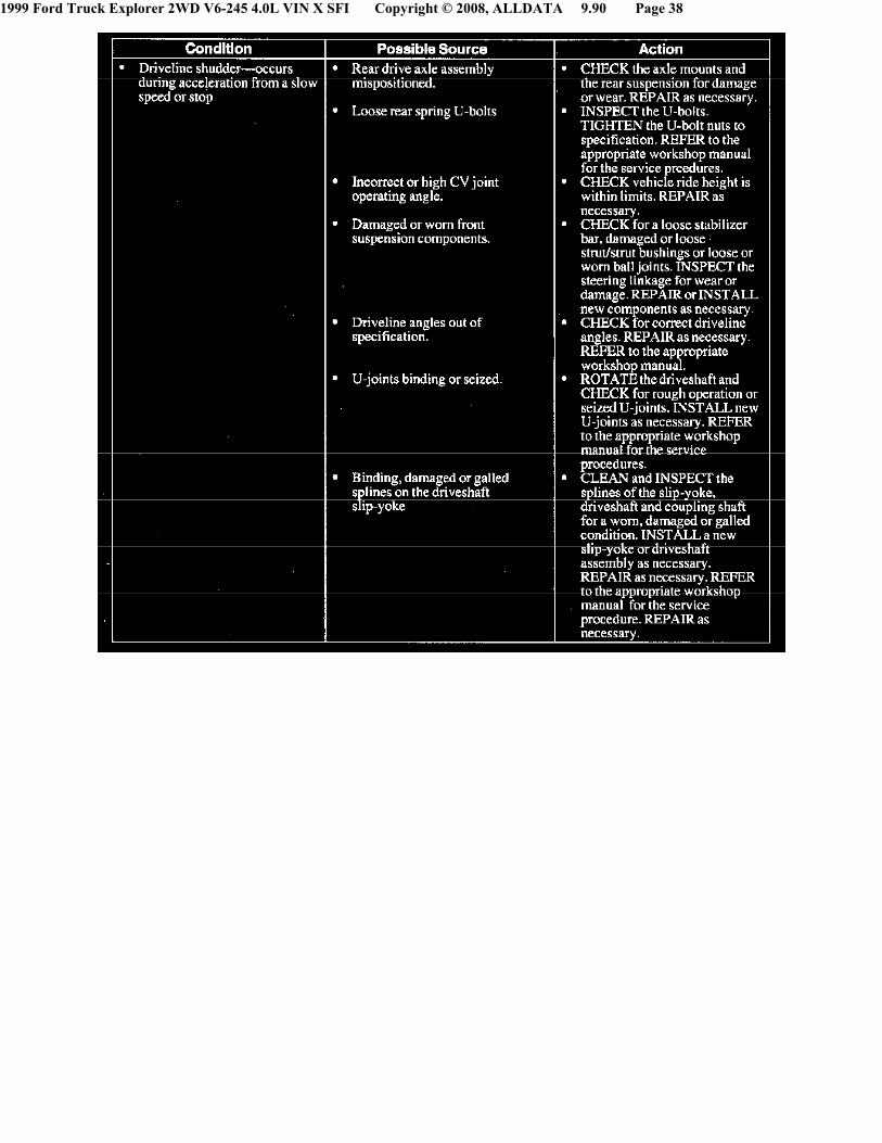
- Driveline shudder. GO to Symptom Chart - Driveline Noise/Vibration.
- Engine vibration. GO to SymptomChart - Engine Noise/Vibration.
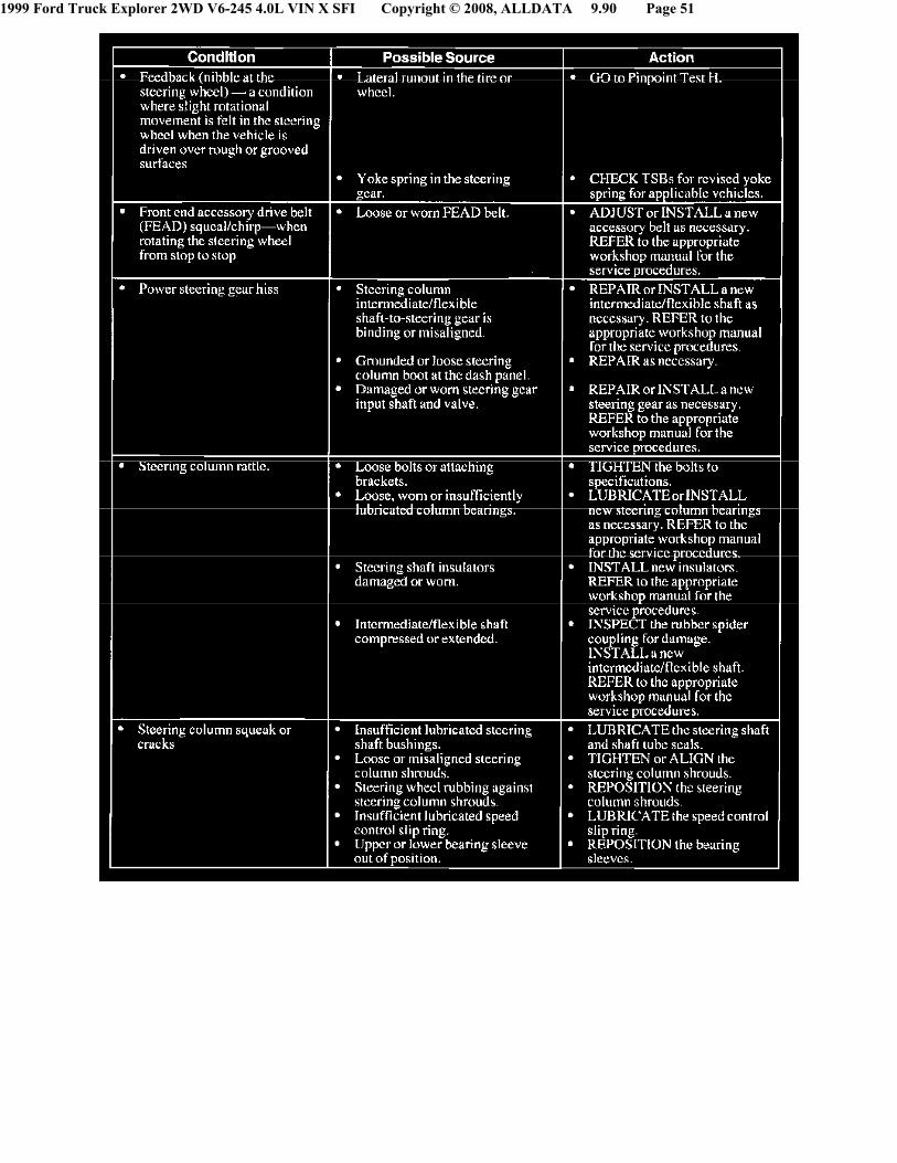
3. Turning noise. GO to Symptom Chart
- Steering Noise/Vibration.
4. Braking.
^ Clicking sound is signaling ABS is active.Acceptable ABS sound.
^ A continuous grinding/squeal. GO toSymptom Chart - BrakeNoise/Vibration.
^ Brake vibration/shudder. GO to SymptomChart - Brake Noise/Vibration.
5. Clutching
^ A noise occurring during clutch operation.GO to Symptom Chart - Transmission(Manual) and Transfer CaseNoise/Vibration.
^ Vibration. GO to Symptom Chart -
1999 Ford Truck Explorer 2WD V6-245 4.0L VIN X SFI Copyright © 2008, ALLDATA 9.90 Page 29
Transmission (Manual) and TransferCase Noise/Vibration.
6. Shifting
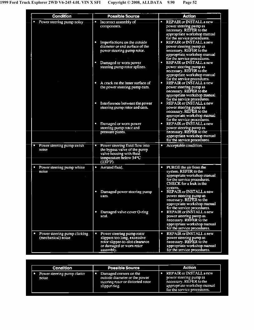
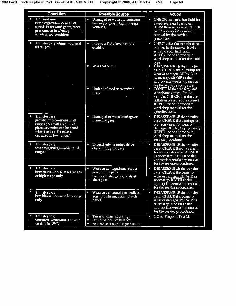
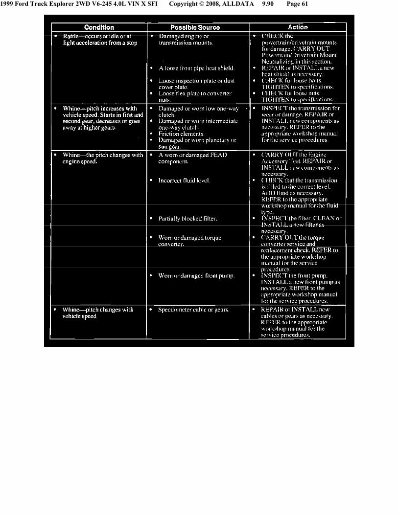
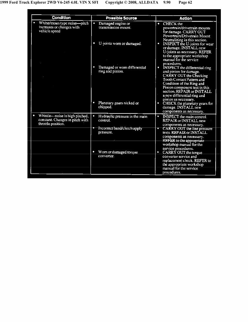
^ Noise or vibration condition related to the transmission (automatic). GO to Symptom Chart - Transmission (Automatic)Noise/Vibration.
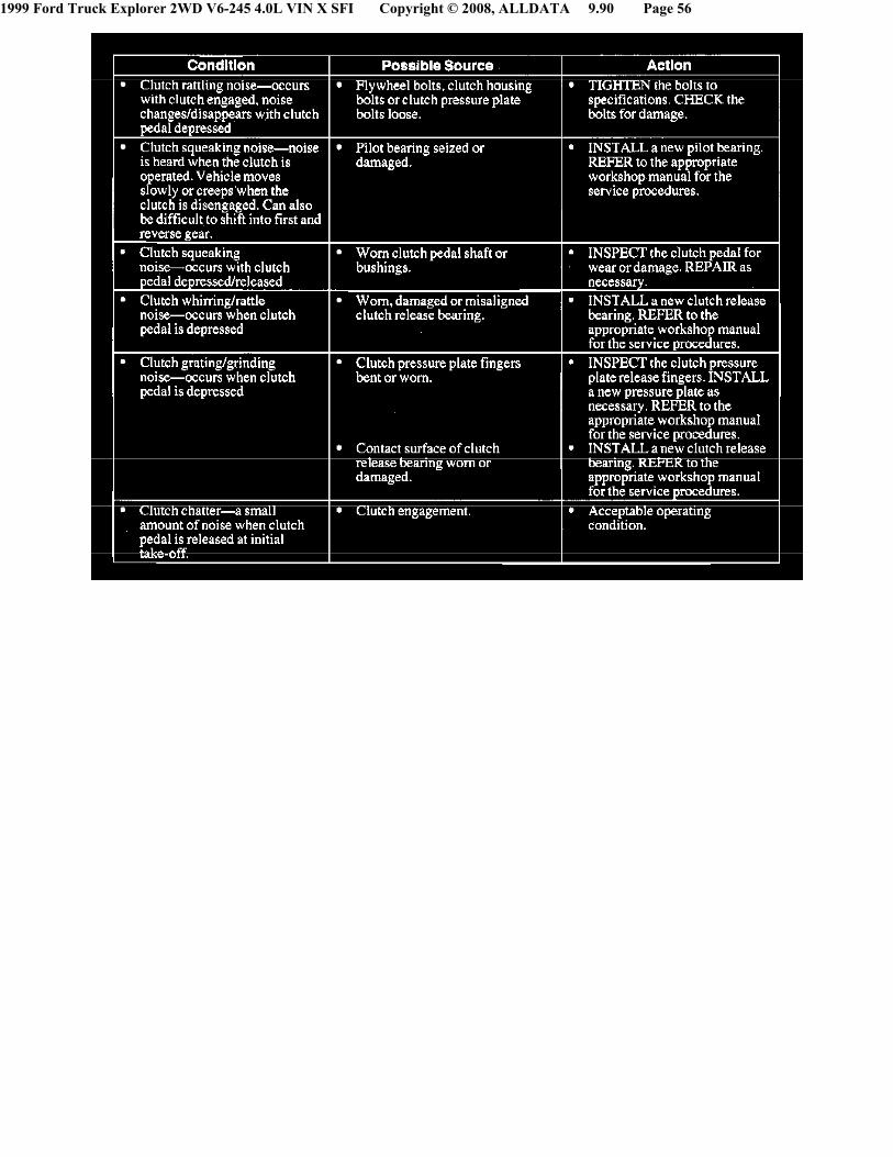
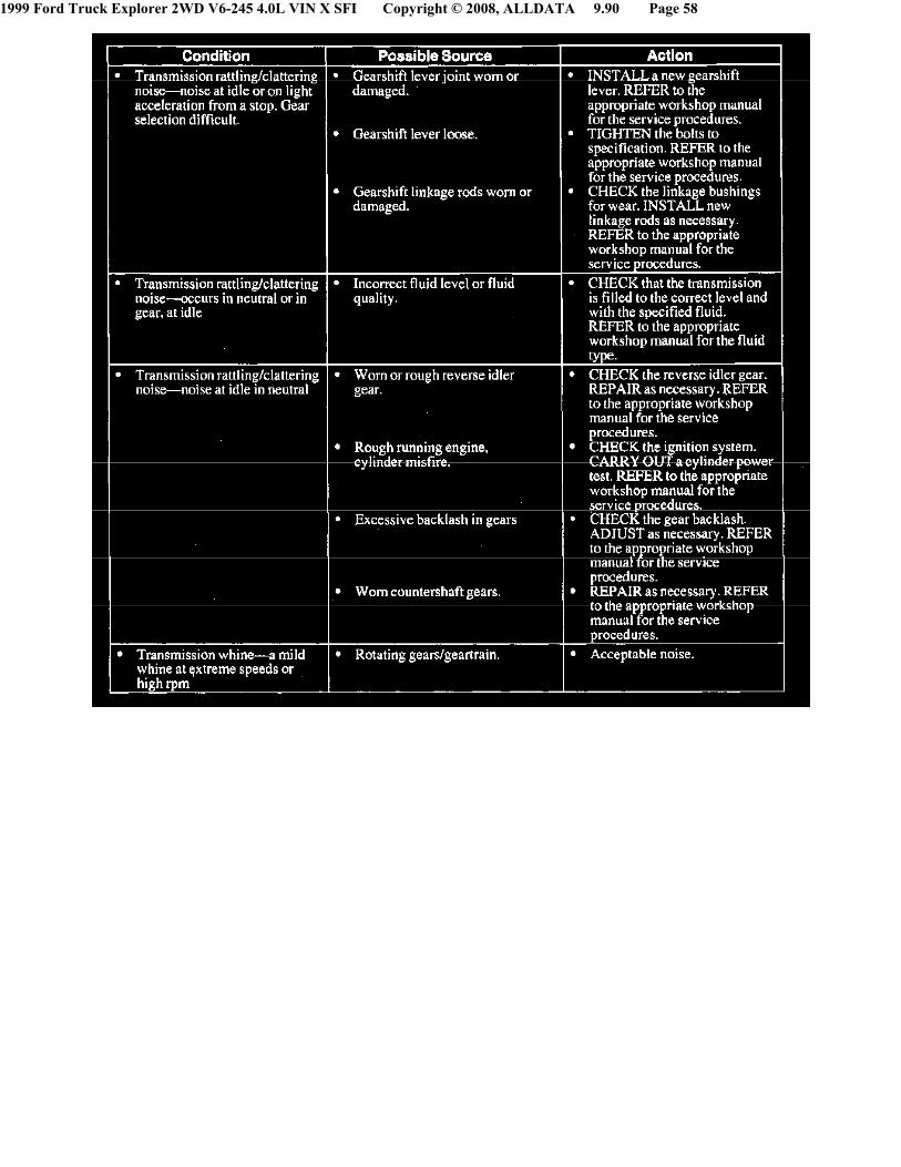
^ Noise or vibration related to the transmission (manual). GO to Symptom Chart - Transmission (Manual) and Transfer CaseNoise/Vibration.
7. Engaged in four-wheel drive. GO to Symptom Chart - Transmission (Manual) and Transfer Case Noise/Vibration.
8. Cruising speeds
^ Accelerator pedal vibration. GO to Symptom Chart - Engine Noise/Vib ration.
^ Driveline vibration. GO to Symptom Chart - Driveline Noise/Vibration.
^ A shimmy or shake. GO to Symptom Chart - Tire Noise/Vibration.
9. Driving at low/medium speeds
^ A wobble or shudder. GO to Symptom Chart - Tire Noise/Vibration.
2. Depends more on where the vehicle is operated
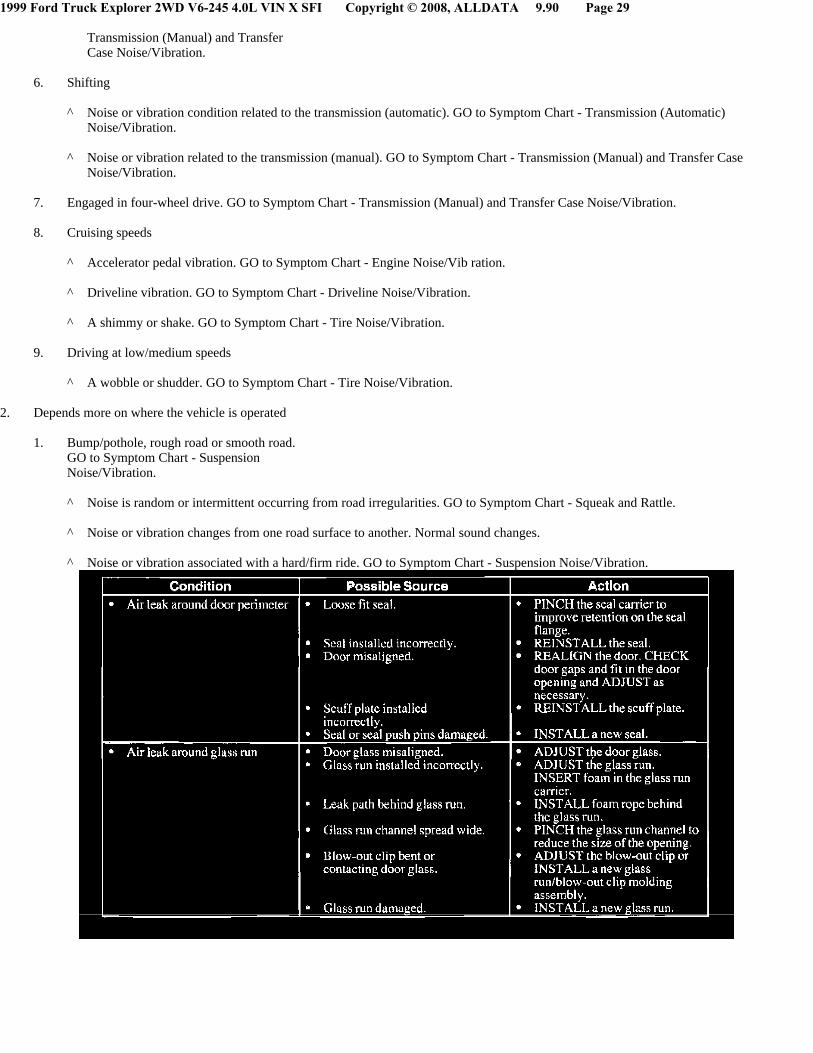
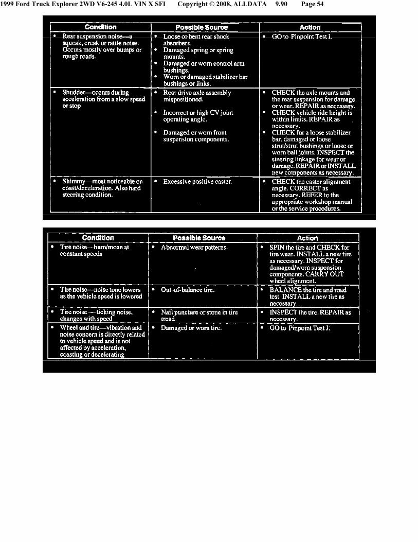
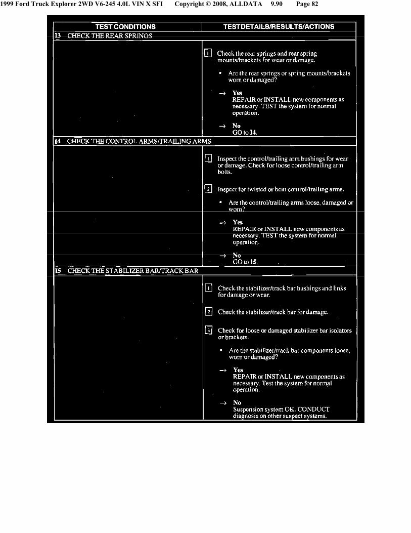
1. Bump/pothole, rough road or smooth road.GO to Symptom Chart - SuspensionNoise/Vibration.
^ Noise is random or intermittent occurring from road irregularities. GO to Symptom Chart - Squeak and Rattle.
^ Noise or vibration changes from one road surface to another. Normal sound changes.
^ Noise or vibration associated with a hard/firm ride. GO to Symptom Chart - Suspension Noise/Vibration.
1999 Ford Truck Explorer 2WD V6-245 4.0L VIN X SFI Copyright © 2008, ALLDATA 9.90 Page 30
1999 Ford Truck Explorer 2WD V6-245 4.0L VIN X SFI Copyright © 2008, ALLDATA 9.90 Page 31
1999 Ford Truck Explorer 2WD V6-245 4.0L VIN X SFI Copyright © 2008, ALLDATA 9.90 Page 32

1999 Ford Truck Explorer 2WD V6-245 4.0L VIN X SFI Copyright © 2008, ALLDATA 9.90 Page 33
1999 Ford Truck Explorer 2WD V6-245 4.0L VIN X SFI Copyright © 2008, ALLDATA 9.90 Page 34

1999 Ford Truck Explorer 2WD V6-245 4.0L VIN X SFI Copyright © 2008, ALLDATA 9.90 Page 35

1999 Ford Truck Explorer 2WD V6-245 4.0L VIN X SFI Copyright © 2008, ALLDATA 9.90 Page 36

1999 Ford Truck Explorer 2WD V6-245 4.0L VIN X SFI Copyright © 2008, ALLDATA 9.90 Page 37
1999 Ford Truck Explorer 2WD V6-245 4.0L VIN X SFI Copyright © 2008, ALLDATA 9.90 Page 38

1999 Ford Truck Explorer 2WD V6-245 4.0L VIN X SFI Copyright © 2008, ALLDATA 9.90 Page 39
1999 Ford Truck Explorer 2WD V6-245 4.0L VIN X SFI Copyright © 2008, ALLDATA 9.90 Page 40
1999 Ford Truck Explorer 2WD V6-245 4.0L VIN X SFI Copyright © 2008, ALLDATA 9.90 Page 41
1999 Ford Truck Explorer 2WD V6-245 4.0L VIN X SFI Copyright © 2008, ALLDATA 9.90 Page 42
1999 Ford Truck Explorer 2WD V6-245 4.0L VIN X SFI Copyright © 2008, ALLDATA 9.90 Page 43
1999 Ford Truck Explorer 2WD V6-245 4.0L VIN X SFI Copyright © 2008, ALLDATA 9.90 Page 44

1999 Ford Truck Explorer 2WD V6-245 4.0L VIN X SFI Copyright © 2008, ALLDATA 9.90 Page 45
1999 Ford Truck Explorer 2WD V6-245 4.0L VIN X SFI Copyright © 2008, ALLDATA 9.90 Page 46
1999 Ford Truck Explorer 2WD V6-245 4.0L VIN X SFI Copyright © 2008, ALLDATA 9.90 Page 47
1999 Ford Truck Explorer 2WD V6-245 4.0L VIN X SFI Copyright © 2008, ALLDATA 9.90 Page 48
1999 Ford Truck Explorer 2WD V6-245 4.0L VIN X SFI Copyright © 2008, ALLDATA 9.90 Page 49

1999 Ford Truck Explorer 2WD V6-245 4.0L VIN X SFI Copyright © 2008, ALLDATA 9.90 Page 50
1999 Ford Truck Explorer 2WD V6-245 4.0L VIN X SFI Copyright © 2008, ALLDATA 9.90 Page 51
1999 Ford Truck Explorer 2WD V6-245 4.0L VIN X SFI Copyright © 2008, ALLDATA 9.90 Page 52

1999 Ford Truck Explorer 2WD V6-245 4.0L VIN X SFI Copyright © 2008, ALLDATA 9.90 Page 53
1999 Ford Truck Explorer 2WD V6-245 4.0L VIN X SFI Copyright © 2008, ALLDATA 9.90 Page 54

1999 Ford Truck Explorer 2WD V6-245 4.0L VIN X SFI Copyright © 2008, ALLDATA 9.90 Page 55
1999 Ford Truck Explorer 2WD V6-245 4.0L VIN X SFI Copyright © 2008, ALLDATA 9.90 Page 56

1999 Ford Truck Explorer 2WD V6-245 4.0L VIN X SFI Copyright © 2008, ALLDATA 9.90 Page 57
1999 Ford Truck Explorer 2WD V6-245 4.0L VIN X SFI Copyright © 2008, ALLDATA 9.90 Page 58

1999 Ford Truck Explorer 2WD V6-245 4.0L VIN X SFI Copyright © 2008, ALLDATA 9.90 Page 59
1999 Ford Truck Explorer 2WD V6-245 4.0L VIN X SFI Copyright © 2008, ALLDATA 9.90 Page 60
1999 Ford Truck Explorer 2WD V6-245 4.0L VIN X SFI Copyright © 2008, ALLDATA 9.90 Page 61
1999 Ford Truck Explorer 2WD V6-245 4.0L VIN X SFI Copyright © 2008, ALLDATA 9.90 Page 62

1999 Ford Truck Explorer 2WD V6-245 4.0L VIN X SFI Copyright © 2008, ALLDATA 9.90 Page 63
1999 Ford Truck Explorer 2WD V6-245 4.0L VIN X SFI Copyright © 2008, ALLDATA 9.90 Page 64
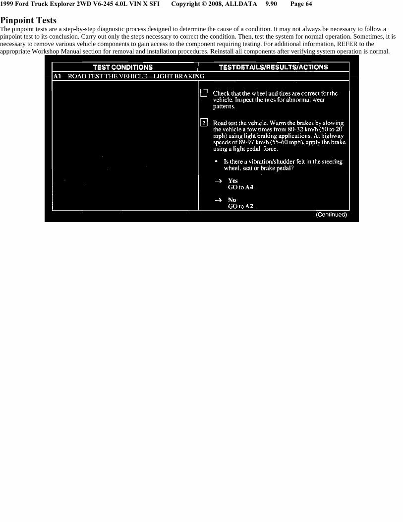
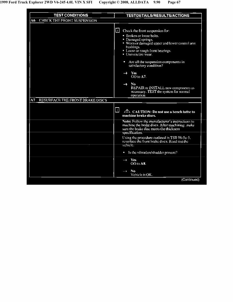
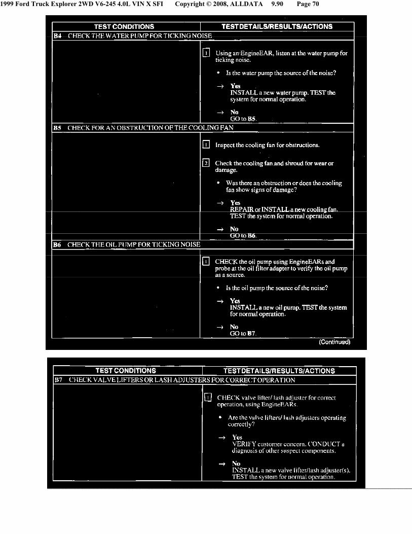
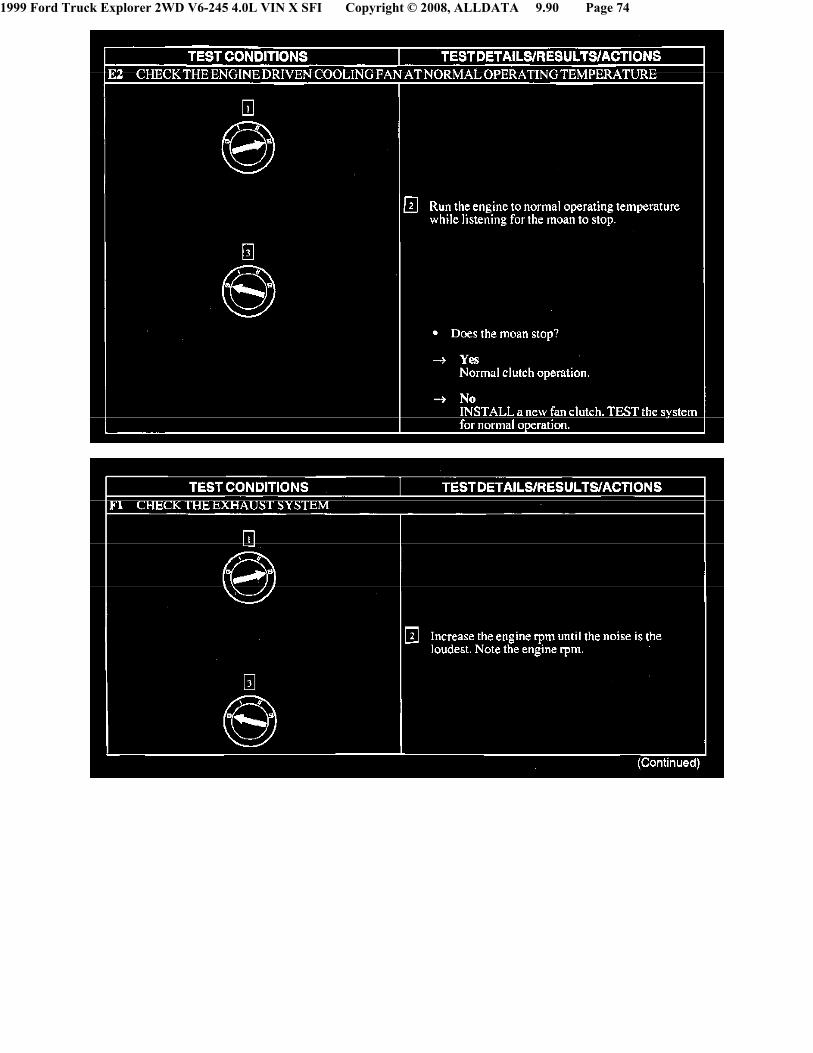
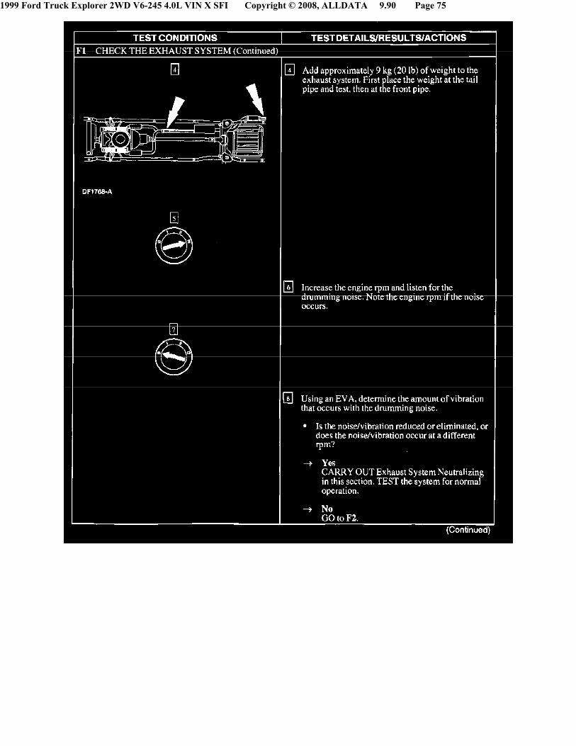
Pinpoint TestsThe pinpoint tests are a step-by-step diagnostic process designed to determine the cause of a condition. It may not always be necessary to follow apinpoint test to its conclusion. Carry out only the steps necessary to correct the condition. Then, test the system for normal operation. Sometimes, it isnecessary to remove various vehicle components to gain access to the component requiring testing. For additional information, REFER to theappropriate Workshop Manual section for removal and installation procedures. Reinstall all components after verifying system operation is normal.

1999 Ford Truck Explorer 2WD V6-245 4.0L VIN X SFI Copyright © 2008, ALLDATA 9.90 Page 65

1999 Ford Truck Explorer 2WD V6-245 4.0L VIN X SFI Copyright © 2008, ALLDATA 9.90 Page 66
1999 Ford Truck Explorer 2WD V6-245 4.0L VIN X SFI Copyright © 2008, ALLDATA 9.90 Page 67

1999 Ford Truck Explorer 2WD V6-245 4.0L VIN X SFI Copyright © 2008, ALLDATA 9.90 Page 68

1999 Ford Truck Explorer 2WD V6-245 4.0L VIN X SFI Copyright © 2008, ALLDATA 9.90 Page 69
1999 Ford Truck Explorer 2WD V6-245 4.0L VIN X SFI Copyright © 2008, ALLDATA 9.90 Page 70

1999 Ford Truck Explorer 2WD V6-245 4.0L VIN X SFI Copyright © 2008, ALLDATA 9.90 Page 71

1999 Ford Truck Explorer 2WD V6-245 4.0L VIN X SFI Copyright © 2008, ALLDATA 9.90 Page 72

1999 Ford Truck Explorer 2WD V6-245 4.0L VIN X SFI Copyright © 2008, ALLDATA 9.90 Page 73
1999 Ford Truck Explorer 2WD V6-245 4.0L VIN X SFI Copyright © 2008, ALLDATA 9.90 Page 74
1999 Ford Truck Explorer 2WD V6-245 4.0L VIN X SFI Copyright © 2008, ALLDATA 9.90 Page 75

1999 Ford Truck Explorer 2WD V6-245 4.0L VIN X SFI Copyright © 2008, ALLDATA 9.90 Page 76

1999 Ford Truck Explorer 2WD V6-245 4.0L VIN X SFI Copyright © 2008, ALLDATA 9.90 Page 77

1999 Ford Truck Explorer 2WD V6-245 4.0L VIN X SFI Copyright © 2008, ALLDATA 9.90 Page 78

1999 Ford Truck Explorer 2WD V6-245 4.0L VIN X SFI Copyright © 2008, ALLDATA 9.90 Page 79

1999 Ford Truck Explorer 2WD V6-245 4.0L VIN X SFI Copyright © 2008, ALLDATA 9.90 Page 80
1999 Ford Truck Explorer 2WD V6-245 4.0L VIN X SFI Copyright © 2008, ALLDATA 9.90 Page 81
1999 Ford Truck Explorer 2WD V6-245 4.0L VIN X SFI Copyright © 2008, ALLDATA 9.90 Page 82

1999 Ford Truck Explorer 2WD V6-245 4.0L VIN X SFI Copyright © 2008, ALLDATA 9.90 Page 83
1999 Ford Truck Explorer 2WD V6-245 4.0L VIN X SFI Copyright © 2008, ALLDATA 9.90 Page 84

1999 Ford Truck Explorer 2WD V6-245 4.0L VIN X SFI Copyright © 2008, ALLDATA 9.90 Page 85
1999 Ford Truck Explorer 2WD V6-245 4.0L VIN X SFI Copyright © 2008, ALLDATA 9.90 Page 86

1999 Ford Truck Explorer 2WD V6-245 4.0L VIN X SFI Copyright © 2008, ALLDATA 9.90 Page 87
1999 Ford Truck Explorer 2WD V6-245 4.0L VIN X SFI Copyright © 2008, ALLDATA 9.90 Page 88

1999 Ford Truck Explorer 2WD V6-245 4.0L VIN X SFI Copyright © 2008, ALLDATA 9.90 Page 89

1999 Ford Truck Explorer 2WD V6-245 4.0L VIN X SFI Copyright © 2008, ALLDATA 9.90 Page 90

1999 Ford Truck Explorer 2WD V6-245 4.0L VIN X SFI Copyright © 2008, ALLDATA 9.90 Page 91

1999 Ford Truck Explorer 2WD V6-245 4.0L VIN X SFI Copyright © 2008, ALLDATA 9.90 Page 92
1999 Ford Truck Explorer 2WD V6-245 4.0L VIN X SFI Copyright © 2008, ALLDATA 9.90 Page 93
1999 Ford Truck Explorer 2WD V6-245 4.0L VIN X SFI Copyright © 2008, ALLDATA 9.90 Page 94
1999 Ford Truck Explorer 2WD V6-245 4.0L VIN X SFI Copyright © 2008, ALLDATA 9.90 Page 95
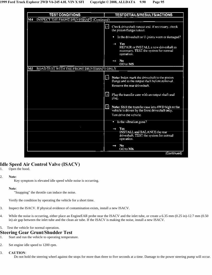
Idle Speed Air Control Valve (ISACV)1. Open the hood.
2. Note: Key symptom is elevated idle speed while noise is occurring.
Note:"Snapping" the throttle can induce the noise.
Verify the condition by operating the vehicle for a short time.
3. Inspect the ISACV. If physical evidence of contamination exists, install a new ISACV.
4. While the noise is occurring, either place an EngineEAR probe near the ISACV and the inlet tube, or create a 6.35 mm (0.25 in)-12.7 mm (0.50in) air gap between the inlet tube and the clean air tube. If the ISACV is making the noise, install a new ISACV.
5. Test the vehicle for normal operation.
Steering Gear Grunt/Shudder Test1. Start and run the vehicle to operating temperature.
2. Set engine idle speed to 1200 rpm.
3. CAUTION: Do not hold the steering wheel against the stops for more than three to five seconds at a time. Damage to the power steering pump will occur.
1999 Ford Truck Explorer 2WD V6-245 4.0L VIN X SFI Copyright © 2008, ALLDATA 9.90 Page 96
Rotate the steering wheel to the RH stop. then turn the steering wheel 90° back from that position. Turn the steering wheel slowly in a 15° to 30°arc.
4. Turn the steering wheel another 90°. Turn the steering wheel slowly in a 15° to 30° arc.
5. Repeat the test with power steering fluid at different temperatures.
6. If a light grunt is heard or a low (50-200Hz) shudder is present, this is a normal steering system condition.
Checking Tooth Contact Pattern/Condition of Ring & PinionThere are two basic types of conditions that will produce ring and pinion noise. The first type is a howl or chuckle produced by broken, cracked,chipped, scored or forcibly damaged gear teeth and is usually quite audible over the entire speed range. The second type of ring and pinion noisepertains to the mesh pattern of the gear pattern. This gear noise can be recognized as it produces a cycling pitch or whine. Ring and pinion noise tendsto peak in a narrow speed range or ranges, and will tend to remain constant in pitch.
1. Raise and support the vehicle.
2. Drain the axle lubricant. Refer to the appropriate workshop manual for the draining procedures.
3. Remove the carrier assembly or the axle housing cover depending on the axle type. Refer to the appropriate workshop manual for the serviceprocedures.
4. Inspect the gear set for scoring or damage.
5. In the following steps, the movement of the contact pattern along the length is indicated as toward the "heel" or "toe" of the differential ring gear.
6. Apply a marking compound to a third of the gear teeth on the differential ring gear. Rotate the differential ring gear several complete turns in bothdirections until a good, clear tooth pattern is obtained. Inspect the contact patterns on the ring gear teeth.
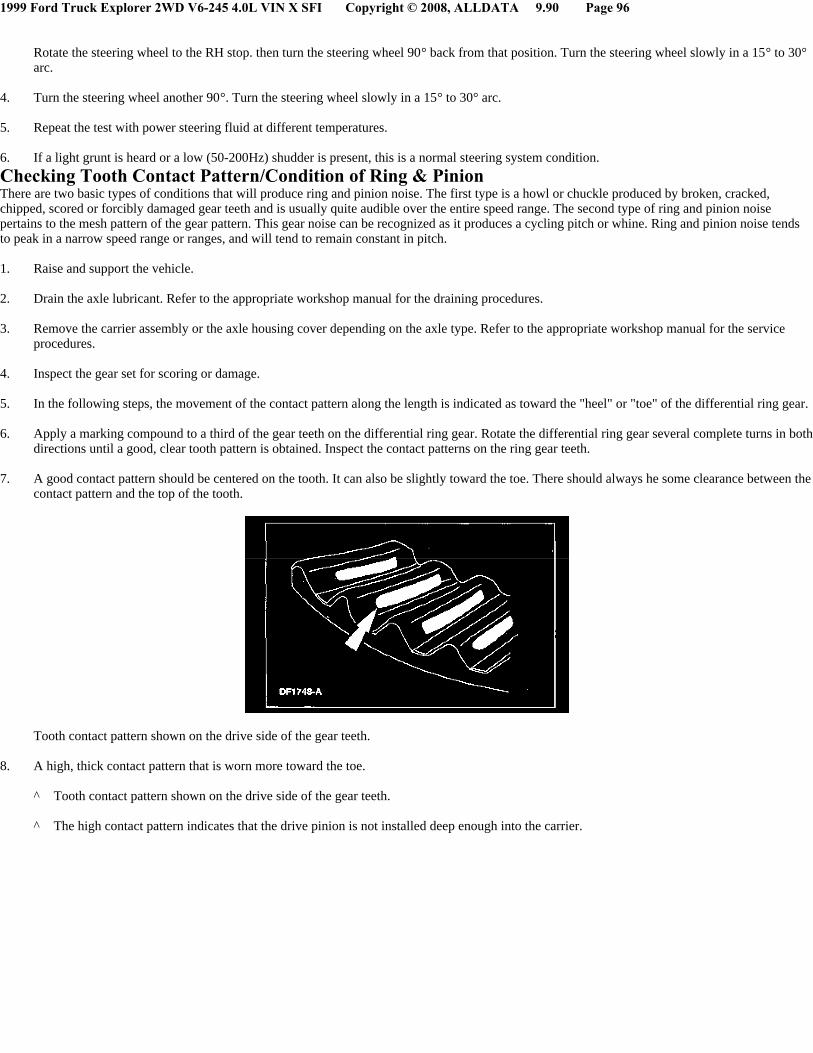
7. A good contact pattern should be centered on the tooth. It can also be slightly toward the toe. There should always he some clearance between thecontact pattern and the top of the tooth.
Tooth contact pattern shown on the drive side of the gear teeth.
8. A high, thick contact pattern that is worn more toward the toe.
^ Tooth contact pattern shown on the drive side of the gear teeth.
^ The high contact pattern indicates that the drive pinion is not installed deep enough into the carrier.
1999 Ford Truck Explorer 2WD V6-245 4.0L VIN X SFI Copyright © 2008, ALLDATA 9.90 Page 97
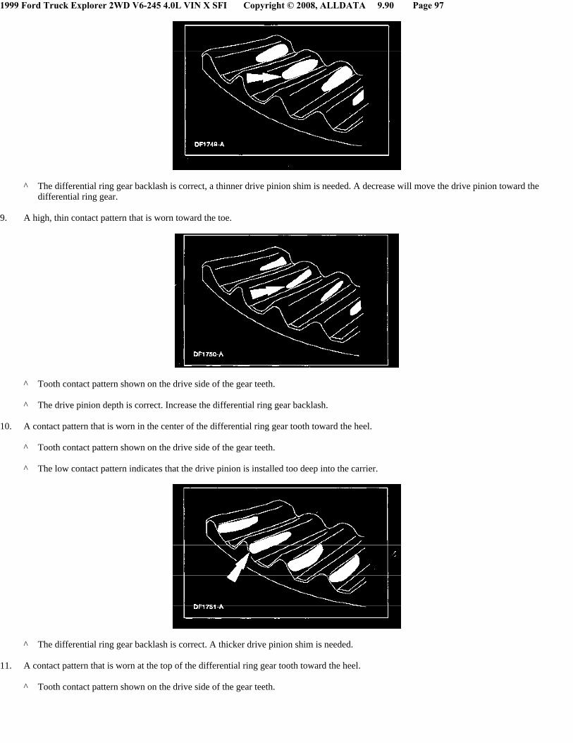
^ The differential ring gear backlash is correct, a thinner drive pinion shim is needed. A decrease will move the drive pinion toward thedifferential ring gear.
9. A high, thin contact pattern that is worn toward the toe.
^ Tooth contact pattern shown on the drive side of the gear teeth.
^ The drive pinion depth is correct. Increase the differential ring gear backlash.
10. A contact pattern that is worn in the center of the differential ring gear tooth toward the heel.
^ Tooth contact pattern shown on the drive side of the gear teeth.
^ The low contact pattern indicates that the drive pinion is installed too deep into the carrier.
^ The differential ring gear backlash is correct. A thicker drive pinion shim is needed.
11. A contact pattern that is worn at the top of the differential ring gear tooth toward the heel.
^ Tooth contact pattern shown on the drive side of the gear teeth.

1999 Ford Truck Explorer 2WD V6-245 4.0L VIN X SFI Copyright © 2008, ALLDATA 9.90 Page 98
^ The pinion gear depth is correct. Decrease the differential ring gear backlash.
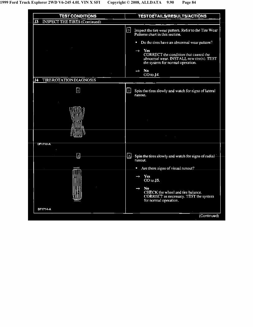
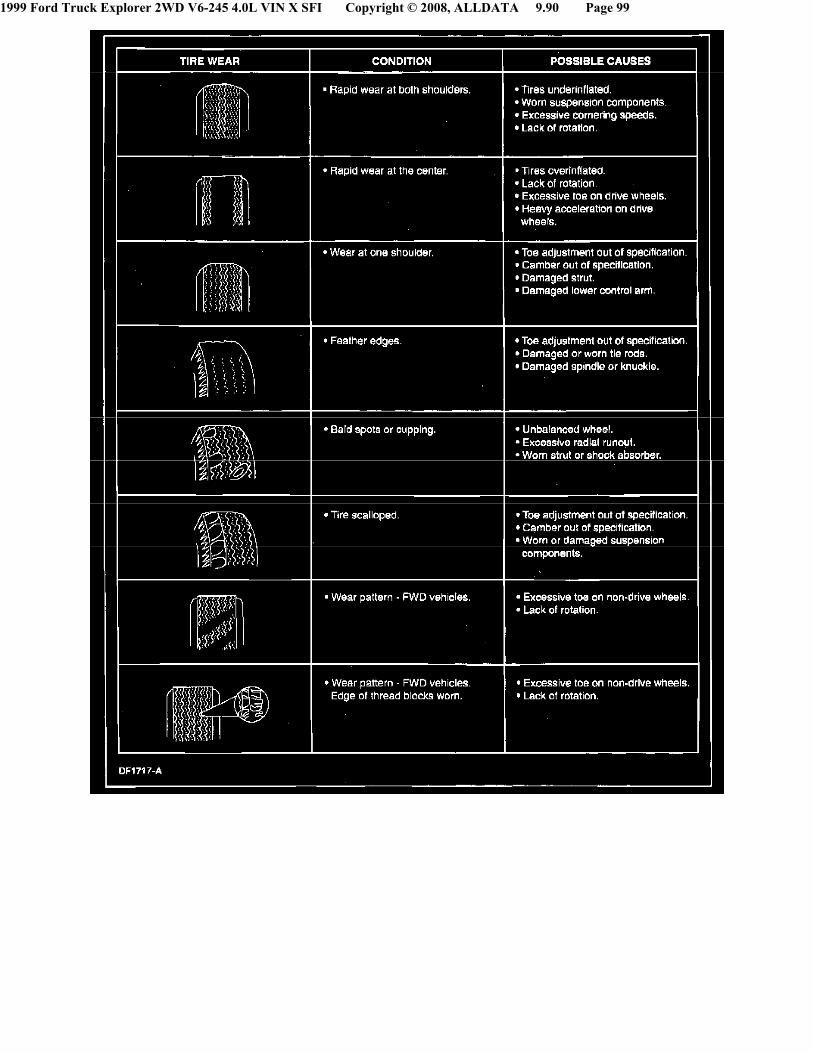
Tire Wear Patterns & Frequency CalculationsWheel and tire NVH concerns are directly related to vehicle speed and are not generally affected by acceleration, coasting or decelerating. Also,out-of-balance wheel and tires can vibrate at more than one speed. A vibration that is affected by the engine rpm or is eliminated by placing thetransmission in NEUTRAL is not related to the tire and wheel. As a general rule, tire and wheel vibrations felt in the steering wheel are related to thefront tire and wheel assemblies. Vibrations felt in the seat or floor are related to the rear tire and wheel assemblies. This can initially isolate a concern tothe front or rear.
Careful attention must be paid to the tire and wheels. There are several symptoms that can~be caused by damaged or worn tire and wheels. Carry out acareful visual inspection of the tires and wheel assemblies. Spin the tires slowly and watch for signs of lateral or radial runout. Refer to the tire wearchart to determine the tire wear conditions and actions.
For a vibration concern, use the vehicle speed to determine tire/wheel frequency and rpm. Calculate tire and wheel rpm and frequency by carrying outand following:
^ Measure the diameter of the tire.
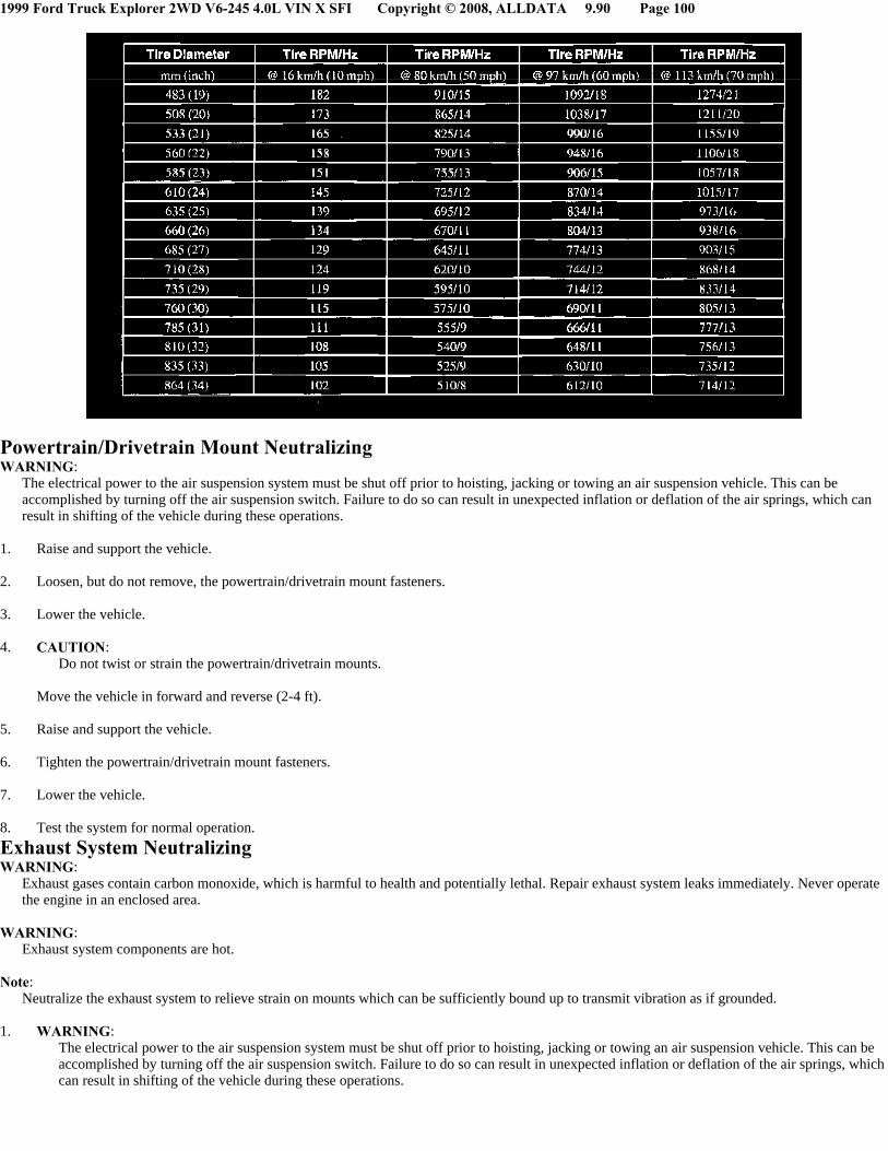
^ Record the speed at which the vibration occurs. Obtain the corresponding tire and wheel rpm and frequency from the Tire Speed and FrequencyChart.
- If the vehicle speed is not listed, divide the vehicle speed at which the vibration occurs by 16 (km/h (10 mph). Multiply that number by 16 km/h(10 mph) tire rpm listed for that tire diameter in the chart. Then divide that number by 60. For example: a 40 mph vibration with 835 mm (33 in)tires. 40 divided by 10 = 4. Multiply 4 by 105 = 420 rpm. Divide 420 rpm by 60 seconds = 7 Hz at 40mph.
1999 Ford Truck Explorer 2WD V6-245 4.0L VIN X SFI Copyright © 2008, ALLDATA 9.90 Page 99
1999 Ford Truck Explorer 2WD V6-245 4.0L VIN X SFI Copyright © 2008, ALLDATA 9.90 Page 100
Powertrain/Drivetrain Mount NeutralizingWARNING:
The electrical power to the air suspension system must be shut off prior to hoisting, jacking or towing an air suspension vehicle. This can beaccomplished by turning off the air suspension switch. Failure to do so can result in unexpected inflation or deflation of the air springs, which canresult in shifting of the vehicle during these operations.
1. Raise and support the vehicle.
2. Loosen, but do not remove, the powertrain/drivetrain mount fasteners.
3. Lower the vehicle.
4. CAUTION: Do not twist or strain the powertrain/drivetrain mounts.
Move the vehicle in forward and reverse (2-4 ft).
5. Raise and support the vehicle.
6. Tighten the powertrain/drivetrain mount fasteners.
7. Lower the vehicle.
8. Test the system for normal operation.
Exhaust System NeutralizingWARNING:
Exhaust gases contain carbon monoxide, which is harmful to health and potentially lethal. Repair exhaust system leaks immediately. Never operatethe engine in an enclosed area.
WARNING: Exhaust system components are hot.
Note:Neutralize the exhaust system to relieve strain on mounts which can be sufficiently bound up to transmit vibration as if grounded.
1. WARNING:The electrical power to the air suspension system must be shut off prior to hoisting, jacking or towing an air suspension vehicle. This can beaccomplished by turning off the air suspension switch. Failure to do so can result in unexpected inflation or deflation of the air springs, whichcan result in shifting of the vehicle during these operations.

1999 Ford Truck Explorer 2WD V6-245 4.0L VIN X SFI Copyright © 2008, ALLDATA 9.90 Page 101
CAUTION:Make sure the system is warmed up to normal operating temperature, as thermal expansion can he the cause of a strain problem.
Raise and support the vehicle.
2. Loosen all exhaust hanger attachments and reposition the hangers until they hang free and straight.
3. Loosen all exhaust flange joints.
4. Place a stand to support the muffler parallel to the vehicle frame with the muffler pipe bracket free of stress.
5. Tighten the muffler connection.
6. Tighten all the exhaust hanger clamps and flanges(tighten the exhaust manifold flange joint last).
^ Verify there is adequate clearance to prevent grounding at any point in the system. Make sure that the catalytic converter and heat shield donot contact the frame rails.
^ After neutralization. the rubber in the exhaust hangers should show some flexibility when movement is applied to the exhaust system.
^ With the exhaust system installed securely and cooled. the rear hanger should be angled forward.
7. Lower the vehicle.
8. Test the exhaust system for normal operation.
Wheel Bearing Check1. WARNING:
The electrical power to the air suspension system must be shut off prior to hoisting, jacking or towing an air suspension vehicle. This can beaccomplished by turning off the air suspension switch. Failure to do so can result in unexpected inflation or deflation of the air springs, whichcan result in shifting of the vehicle during these operations.
Raise the vehicle until the front tires are off the floor.
^ Make sure the wheels are in a straight forward position.
2. Note: Make sure the wheel rotates freely and that the brake pads are retraced sufficiently to allow free movement of the tire and wheel assembly.
Spin the tire by hand to check the wheel bearings for roughness.
1999 Ford Truck Explorer 2WD V6-245 4.0L VIN X SFI Copyright © 2008, ALLDATA 9.90 Page 102
3. Grip each front tire at the top and bottom and move the wheel inward and outward while lifting the weight of the tire off the front wheel bearing.
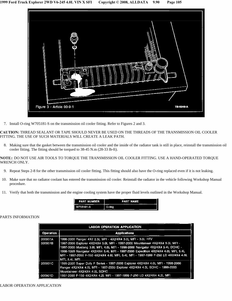
4. If the tire and wheel (hub) is loose on the spindle, does not rotate freely, or has a rough feeling when spun, carry out one of the following:
^ On vehicles with inner and outer hearings, Inspect the hearings and cups for wear or damage. Adjust or install new bearings and cups asnecessary.
^ On vehicles with one sealed bearing, install a new wheel hub. Refer to the appropriate workshop manual for the service procedures.
Technical Service Bulletin # 00-9-1 Date: 000501
A/T Cooler - Fluid Leaks at RadiatorArticle No.00-9-1
DATE5/1/00
TITLELEAK - TRANSMISSION FLUID LEAKS AT RADIATOR - VEHICLES EQUIPPED WITH AUTOMATIC TRANSMISSION ANDTRANSMISSION OIL COOLER IN RADIATOR END TANK
FORD:

1999 Ford Truck Explorer 2WD V6-245 4.0L VIN X SFI Copyright © 2008, ALLDATA 9.90 Page 103
1997-2000 MUSTANG, EXPEDITION, EXPLORER, F-150, F-250 LD1998-2000 RANGER1999-2000 SUPER DUTY F SERIES
LINCOLN: 1998-2000 NAVIGATOR
MERCURY: 1998-2000 MOUNTAINEER
This TSB is being republished in its entirety to update the vehicles affected and to update the Service Procedure.
ISSUETransmission fluid may leak between the radiator transmission oil cooler and the transmission oil cooler fitting (NOT the cooler line into the fitting),which may result in a residue of transmission fluid on the radiator tank around the transmission oil cooler fitting. This may be caused by insufficientthread sealer on the transmission oil cooler fitting.
NOTE: THIS TSB DOES NOT APPLY TO TRANSMISSION FLUID LEAKAGE AT THE TRANSMISSION LINE TO TRANSMISSION OILCOOLER FITTING.
ACTIONInstall O-ring W705181-S onto the transmission oil cooler fitting. The O-ring is designed to seal the leak and reduce the possibility of transmissionfluid leakage. Refer to the following Service Procedure for details.
SERVICE PROCEDURE
1. Verify that transmission fluid is leaking between the transmission oil cooler and the transmission oil cooler fitting (NOT the transmission coolerline fitting into the transmission oil cooler fitting). Refer to Figure 1.

1999 Ford Truck Explorer 2WD V6-245 4.0L VIN X SFI Copyright © 2008, ALLDATA 9.90 Page 104
2. Remove the radiator from the vehicle following Workshop Manual procedure. Place the radiator on a flat surface so that the transmission oilcooler fittings are facing upward. Refer to Figure 2.
3. Clean the area around the transmission oil cooler fitting. This will insure that contaminants do not enter the transmission oil cooler when thetransmission oil cooler fittings are removed.
CAUTION: OIL-BASED SOLVENTS AND CLEANERS SHOULD NOT BE USED WHEN CLEANING THE RADIATOR. OIL-BASEDSOLVENTS AND CLEANERS CAN DAMAGE THE RADIATOR END TANK SEALS AND CAUSE LEAKS.
4. Remove the upper transmission oil cooler fitting.
NOTE: REMOVE ONLY ONE (1) TRANSMISSION OIL COOLER FITTING AT A TIME, OTHERWISE THE COOLER MAY DROP INTO THE RADIATOR.
5. Once the fitting is removed from the transmission oil cooler, verify that there is a gasket between the transmission oil cooler and the inside of the radiator tank. If there is no gasket, replace the radiator. If the gasket is in place, continue to Step 6.
6. Inspect the transmission oil cooler fitting threads for damage. If the threads are damaged, replace the radiator. If the threads show no sign ofdamage, continue to Step 7.
1999 Ford Truck Explorer 2WD V6-245 4.0L VIN X SFI Copyright © 2008, ALLDATA 9.90 Page 105
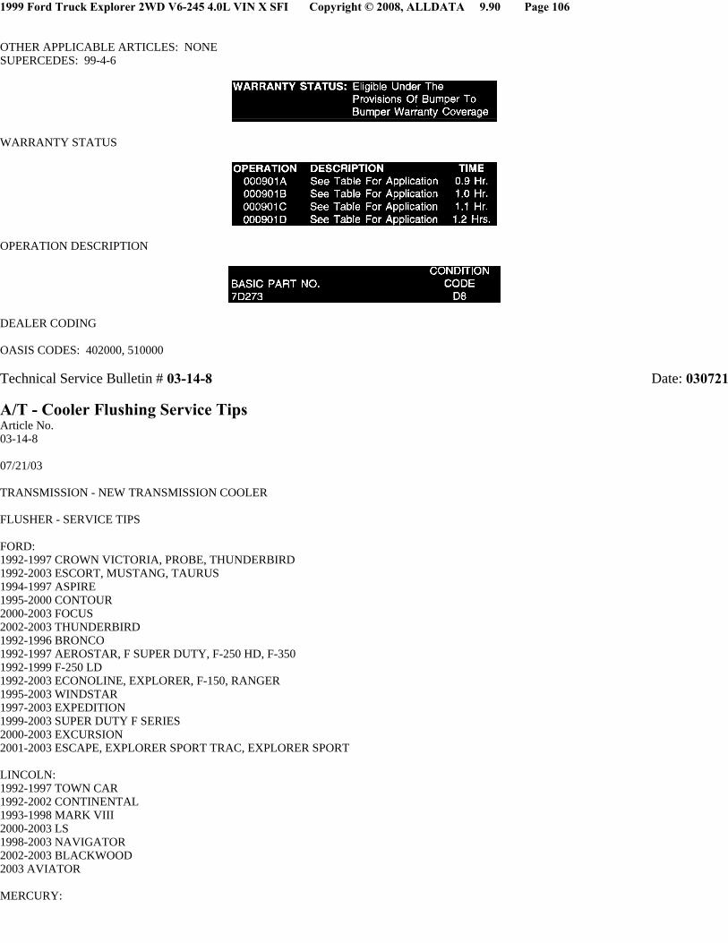
7. Install O-ring W705181-S on the transmission oil cooler fitting. Refer to Figures 2 and 3.
CAUTION: THREAD SEALANT OR TAPE SHOULD NEVER BE USED ON THE THREADS OF THE TRANSMISSION OIL COOLERFITTING. THE USE OF SUCH MATERIALS WILL CREATE A LEAK PATH.
8. Making sure that the gasket between the transmission oil cooler and the inside of the radiator tank is still in place, reinstall the transmission oilcooler fitting. The fitting should be torqued to 38-45 N.m (28-33 lb-ft).
NOTE:: DO NOT USE AIR TOOLS TO TORQUE THE TRANSMISSION OIL COOLER FITTING. USE A HAND-OPERATED TORQUEWRENCH ONLY.
9. Repeat Steps 2-8 for the other transmission oil cooler fitting. This fitting should also have the O-ring replaced even if it is not leaking.
10. Make sure that no radiator coolant has entered the transmission oil cooler. Reinstall the radiator in the vehicle following Workshop Manualprocedure.
11. Verify that both the transmission and the engine cooling system have the proper fluid levels outlined in the Workshop Manual.
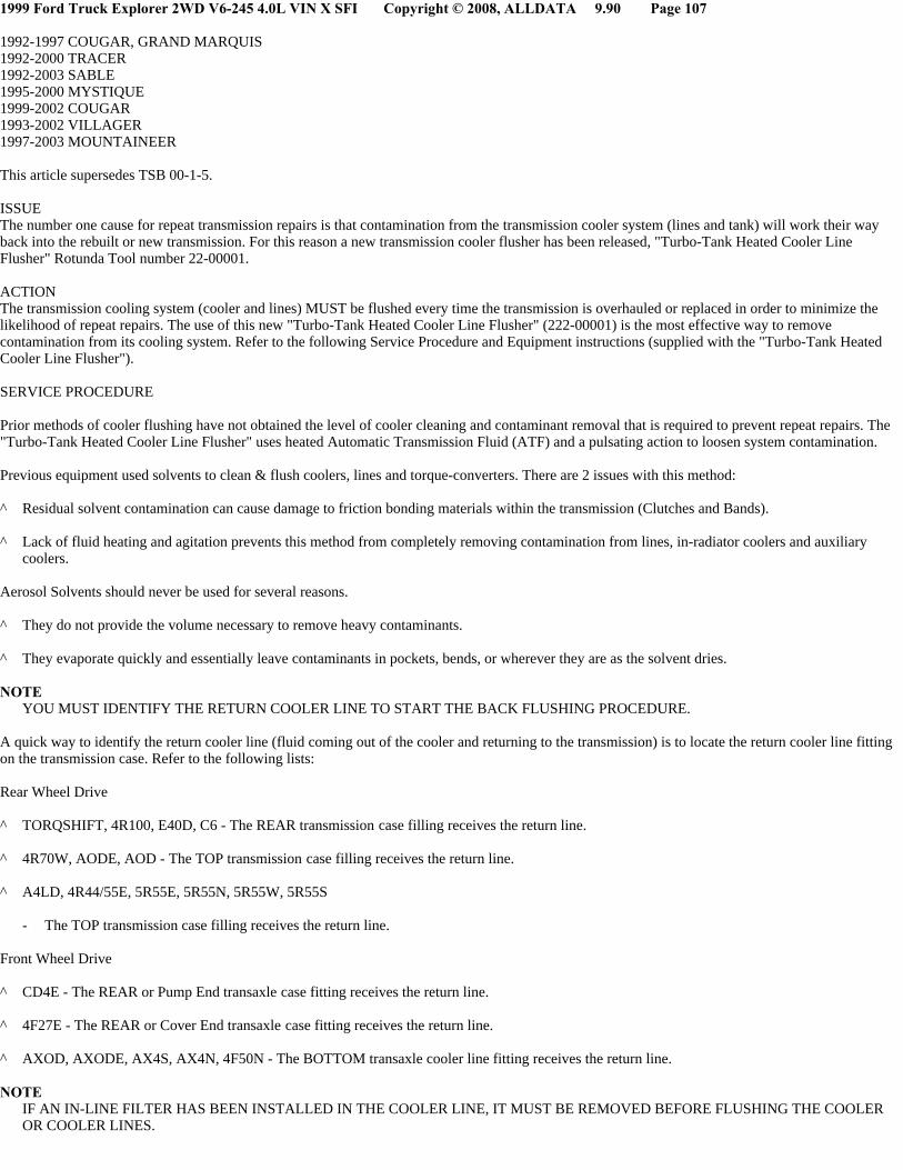
PARTS INFORMATION
LABOR OPERATION APPLICATION
1999 Ford Truck Explorer 2WD V6-245 4.0L VIN X SFI Copyright © 2008, ALLDATA 9.90 Page 106
OTHER APPLICABLE ARTICLES: NONESUPERCEDES: 99-4-6
WARRANTY STATUS
OPERATION DESCRIPTION
DEALER CODING
OASIS CODES: 402000, 510000
Technical Service Bulletin # 03-14-8 Date: 030721
A/T - Cooler Flushing Service TipsArticle No.03-14-8
07/21/03
TRANSMISSION - NEW TRANSMISSION COOLER
FLUSHER - SERVICE TIPS
FORD:1992-1997 CROWN VICTORIA, PROBE, THUNDERBIRD1992-2003 ESCORT, MUSTANG, TAURUS1994-1997 ASPIRE1995-2000 CONTOUR2000-2003 FOCUS2002-2003 THUNDERBIRD1992-1996 BRONCO1992-1997 AEROSTAR, F SUPER DUTY, F-250 HD, F-3501992-1999 F-250 LD1992-2003 ECONOLINE, EXPLORER, F-150, RANGER1995-2003 WINDSTAR1997-2003 EXPEDITION1999-2003 SUPER DUTY F SERIES2000-2003 EXCURSION2001-2003 ESCAPE, EXPLORER SPORT TRAC, EXPLORER SPORT
LINCOLN:1992-1997 TOWN CAR1992-2002 CONTINENTAL1993-1998 MARK VIII2000-2003 LS1998-2003 NAVIGATOR2002-2003 BLACKWOOD2003 AVIATOR
MERCURY:
1999 Ford Truck Explorer 2WD V6-245 4.0L VIN X SFI Copyright © 2008, ALLDATA 9.90 Page 107
1992-1997 COUGAR, GRAND MARQUIS1992-2000 TRACER1992-2003 SABLE1995-2000 MYSTIQUE1999-2002 COUGAR1993-2002 VILLAGER1997-2003 MOUNTAINEER
This article supersedes TSB 00-1-5.
ISSUEThe number one cause for repeat transmission repairs is that contamination from the transmission cooler system (lines and tank) will work their wayback into the rebuilt or new transmission. For this reason a new transmission cooler flusher has been released, "Turbo-Tank Heated Cooler LineFlusher" Rotunda Tool number 22-00001.
ACTIONThe transmission cooling system (cooler and lines) MUST be flushed every time the transmission is overhauled or replaced in order to minimize thelikelihood of repeat repairs. The use of this new "Turbo-Tank Heated Cooler Line Flusher" (222-00001) is the most effective way to removecontamination from its cooling system. Refer to the following Service Procedure and Equipment instructions (supplied with the "Turbo-Tank HeatedCooler Line Flusher").
SERVICE PROCEDURE
Prior methods of cooler flushing have not obtained the level of cooler cleaning and contaminant removal that is required to prevent repeat repairs. The"Turbo-Tank Heated Cooler Line Flusher" uses heated Automatic Transmission Fluid (ATF) and a pulsating action to loosen system contamination.
Previous equipment used solvents to clean & flush coolers, lines and torque-converters. There are 2 issues with this method:
^ Residual solvent contamination can cause damage to friction bonding materials within the transmission (Clutches and Bands).
^ Lack of fluid heating and agitation prevents this method from completely removing contamination from lines, in-radiator coolers and auxiliarycoolers.
Aerosol Solvents should never be used for several reasons.
^ They do not provide the volume necessary to remove heavy contaminants.
^ They evaporate quickly and essentially leave contaminants in pockets, bends, or wherever they are as the solvent dries.
NOTEYOU MUST IDENTIFY THE RETURN COOLER LINE TO START THE BACK FLUSHING PROCEDURE.
A quick way to identify the return cooler line (fluid coming out of the cooler and returning to the transmission) is to locate the return cooler line fittingon the transmission case. Refer to the following lists:
Rear Wheel Drive
^ TORQSHIFT, 4R100, E40D, C6 - The REAR transmission case filling receives the return line.
^ 4R70W, AODE, AOD - The TOP transmission case filling receives the return line.
^ A4LD, 4R44/55E, 5R55E, 5R55N, 5R55W, 5R55S
- The TOP transmission case filling receives the return line.
Front Wheel Drive
^ CD4E - The REAR or Pump End transaxle case fitting receives the return line.
^ 4F27E - The REAR or Cover End transaxle case fitting receives the return line.
^ AXOD, AXODE, AX4S, AX4N, 4F50N - The BOTTOM transaxle cooler line fitting receives the return line.
NOTEIF AN IN-LINE FILTER HAS BEEN INSTALLED IN THE COOLER LINE, IT MUST BE REMOVED BEFORE FLUSHING THE COOLEROR COOLER LINES.

1999 Ford Truck Explorer 2WD V6-245 4.0L VIN X SFI Copyright © 2008, ALLDATA 9.90 Page 108
Purge the cooler and cooler line before flushing:
Located on the "Turbo-Tank Heated Cooler Line Flusher" is a fluid transfer and purge valve. This valve can be used to purge the cooler and cooler linesof contaminated fluid before starting the back flush procedure of the fluid cooling system (refer to step 5a of this Service Procedure or Equipmentinstructions, supplied with the "Turbo-Tank Heated Cooler Line Flusher").
Flush Procedure
1. Check and top off fluid level of the "Turbo-Tank Heated Cooler Line Flusher" tank with transmission fluid.
2. Allow the fluid in the flusher 15-30 minutes to heat up to 140° F (60° C) before using.
3. Install line adapters into the transmission cooler lines.
4. Attach the flusher's blue line to the transmission return cooler line quick disconnect.
5. Attach the flusher's red line to the transmission outlet cooler line quick disconnect.
a. Follow equipment instructions, to purge cooler lines and cooler prior to starting flushing procedure (using factory installed purge valve andclear hose on "Turbo-Tank Heated Cooler Line Flusher").
6. Allow the cooling system to back-flush for 10-15 minutes, then flush the cooler in a forward/normal flow direction for an additional 10-15minutes.
For ordering information on this new "Turbo-Tank Heated Cooler Line Flusher" (222-00001), contact Rotunda at 800-ROTUNDA (800-768-8632 oroutside U.S. 262-656-5805).
CAUTIONTHIS FLUSHER CANNOT BE USED TO FLUSH COOLERS ON VEHICLES EQUIPPED WITH THE TEMPERATURE BYPASS-TYPE TRANSMISSION COOLER CURRENTLY FOUND IN 1998-2003 CROWN VICTORIA, GRAND MARQUIS, AND TOWN CAR VEHICLES.
OTHER APPLICABLE ARTICLES: NONESUPERSEDES: 00-1-5WARRANTY STATUS: INFORMATION ONLY
DisclaimerTechnical Service Bulletin # 99-18-5 Date: 990906
A/T - 4R70W TCIL ON/Code P0782/Delayed/No 2-3 UpshiftArticle No.99-18-5
09/06/99
^ TRANSMISSION CONTROL INDICATOR LAMP(TCIL) - TCIL ILLUMINATED WITH DIAGNOSTICTROUBLE CODE (DTC) P0782 STORED INMEMORY - VEHICLES BUILT BETWEEN 3/15/1997AND 12/31/1998 AND WITH 4R70W TRANSMISSION
^ TRANSMISSION - 4R70W - DELAYED OR NO 2-3 UPSHIFT - VEHICLES BUILT BETWEEN 3/15/1997 AND 12/31/1998
FORD:1997-1999 CROWN VICTORIA, MUSTANG, ECONOLINE, EXPEDITION, EXPLORER, F-150, F-250 LD
LINCOLN:1997-1998 MARK VIII1997-1999 TOWN CAR

1999 Ford Truck Explorer 2WD V6-245 4.0L VIN X SFI Copyright © 2008, ALLDATA 9.90 Page 109
MERCURY:1997-1999 GRAND MARQUIS, MOUNTAINEER
This TSB article is being republished in its entirety to revise the Service Procedure.
ISSUEA perceived 2-3 delayed upshift, primarily when the transmission is cold, may be evident on some vehicles. The Powertrain Control Module (PCM)strategy is designed to delay shifts in some vehicles when Transmission Fluid Temperature (TFT) is below approximately 21°C (70°F) for taster heaterwarmup. The 2-3 shift may be delayed approximately 14-24 km/h (9-15 mph) when compared to the shift speed charts listed in the appropriate Serviceor Workshop Manual. A leaking 2-3 accumulator may cause Diagnostic Trouble Code (DTC) P0782.
ACTIONVerify if delayed upshift is normal cold shift scheduling or a possible leak past the large diameter 2-3 accumulator seal. Refer to the following ServiceProcedure for details.
SERVICE PROCEDURE
1. Using New Generation Star (NGS) Tester, perform all self tests and record DTCs.
2. Monitor rpm, and gear command Parameter Identification Displays (PIDs) with the NGS Tester during the 2-3 shift.
3. If engine rpm decreases within 1-2 seconds after the gear command has changed on the NGS Tester, then vehicle has upshifted properly and norepair is necessary. If engine rpm does not drop within 1-2 seconds, continue to Step 4.
4. If engine rpm does not drop when the PCM commands third gear, then replace the 2-3 accumulator piston using the revised Accumulator Piston(F7AZ-7H292-AB). Refer to the appropriate Service or Workshop Manual for replacement procedure.
PART NUMBER PART NAME
F7AZ-7H292-AB Accumulator Piston
OTHER APPLICABLE ARTICLES: NONE
SUPERSEDES: 99-1-3
WARRANTY STATUS: Eligible Under the Provisions Of Bumper To Bumper Warranty Coverage
OPERATION DESCRIPTION TIME
991805A Replace Accumulator 1.8 Hrs.Piston Per ServiceProcedure (IncludesDiagnosis)
991805B Diagnosis Only (Do Not 0.8 Hr.Use With Operation A)
DEALER CODINGCONDITION
BASIC PART NO CODE7H292 42
OASIS CODES: 501000, 504000Technical Service Bulletin # 99-19-7 Date: 990920
A/T - 4R70W TCIL/MIL ON/Trouble Codes StoredArticle No.99-19-7
09/20/99
^ LAMP - INTERMITTENT MALFUNCTION INDICATORLAMP (MIL) ILLUMINATION - DIAGNOSTICTROUBLE CODES (DTCS) P0741, P0750, P0755,AND P1746 MAY BE STORED IN MEMORY -
1999 Ford Truck Explorer 2WD V6-245 4.0L VIN X SFI Copyright © 2008, ALLDATA 9.90 Page 110
VEHICLES BUILT FROM 8/1/1998 THROUGH5/1/1999 WITH 4R70W TRANSMISSION
^ LAMP - INTERMITTENT TRANSMISSION CONTROLINDICATOR LAMP (TCIL) ILLUMINATION - DIAGNOSTIC TROUBLE CODES (DTCS) P0741,P0750, P0755, AND P1746 MAY BE STORED INMEMORY - VEHICLES BUILT FROM 8/1/1998THROUGH 5/1/1999 WITH 4R70W TRANSMISSION
^ TRANSMISSION - 4R7OW - INTERMITTENTTRANSMISSION CONTROL INDICATOR LAMP(TCIL) ILLUMINATION - DIAGNOSTIC TROUBLECODES (DTCS) P0741, P0750, P0755, AND P1746MAY BE STORED IN MEMORY - VEHICLES BUILTFROM 8/1/1998 THROUGH 5/1/1999
FORD:1999 CROWN VICTORIA, MUSTANG, ECONOLINE, EXPEDITION, EXPLORER, F-150, F-250 LD
LINCOLN:1999 TOWN CAR
MERCURY:1999 GRAND MARQUIS, MOUNTAINEER
This TSB article is being republished in its entirety to include additional vehicles and to correct the Service Procedure.
ISSUEIntermittent Transmission Control Indicator Lamp (TCIL) or Malfunction Indicator Lamp (MIL) illumination may occur on some vehicles. Thefollowing Diagnostic Trouble Codes (DTCs) may be stored in memory: P0741, P0750, P0755, and P1746. This may be caused by the solenoidinterconnect molded lead frame not being fully seated or the bulkhead interconnect clips not being fully seated between the solenoid interconnectmolded lead frame and bulkhead interconnect.
ACTIONVerify the solenoid interconnect molded lead frame (-7G276-) is fully seated. If no concern is found, then inspect the bulkhead interconnect terminalsfor spread and/or not fully recessed. Refer to the following Service Procedure for details.
SERVICE PROCEDURE
1. Perform normal diagnosis for DTCs retrieved as outlined in the appropriate 1999 Workshop Manual. If root cause is not determined, continuewith this TSB.
2. Remove the transmission oil pan per the appropriate model Workshop Manual, Section 307-01.
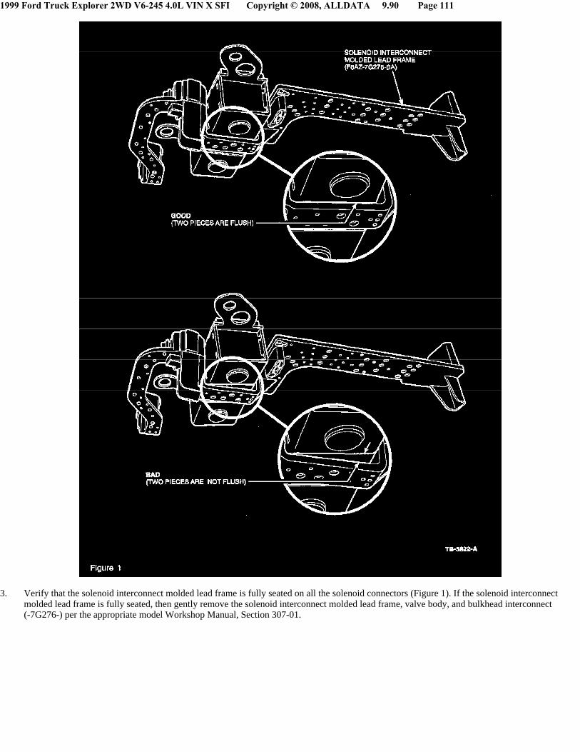
1999 Ford Truck Explorer 2WD V6-245 4.0L VIN X SFI Copyright © 2008, ALLDATA 9.90 Page 111
3. Verify that the solenoid interconnect molded lead frame is fully seated on all the solenoid connectors (Figure 1). If the solenoid interconnectmolded lead frame is fully seated, then gently remove the solenoid interconnect molded lead frame, valve body, and bulkhead interconnect(-7G276-) per the appropriate model Workshop Manual, Section 307-01.

1999 Ford Truck Explorer 2WD V6-245 4.0L VIN X SFI Copyright © 2008, ALLDATA 9.90 Page 112
4. With the bulkhead interconnect removed, push down on the terminal cover and check to see if any of the terminals are slightly protruding abovethe plastic cover (Figure 2). Gently pry off the terminal cover using a small screwdriver (Figure 3). With the terminal cover off, inspect thebulkhead interconnect for spreading terminals (Figure 4). If the bulkhead interconnect terminals are spread or slightly protruding above theplastic cover, replace with a new Bulkhead Interconnect (F8AZ-7G276-AA).
5. Reassemble.
PART NUMBER
F8AZ-7G276-AA Bulkhead InterconnectF8AZ-7G276-BA Solenoid Interconnect
OTHER APPLICABLE ARTICLES: NONE
SUPERSEDES: 99-18-6
WARRANTY STATUS: Eligible Under The Provisions Of Bumper To Bumper Warranty Coverage And Emissions Warranty Coverage
1999 Ford Truck Explorer 2WD V6-245 4.0L VIN X SFI Copyright © 2008, ALLDATA 9.90 Page 113
OPERATION DESCRIPTION TIME
991907A Perform Inspection And 1.3 Hrs.Replace BulkheadInterconnect
DEALER CODINGCONDITION
BASIC PART NO. CODE7G276 42
OASIS CODES: 206000, 501000, 502000, 504000
Technical Service Bulletin # 03-22-10 Date: 031110
A/T - No 2nd, 3rd Gear/No Engine Braking/DTC's SetArticle No.03-22-10
11/10/03
TRANSMISSION - 4R44E - 4R55E - 5R44E - 5R55E -LOW LINE PRESSURE READING AT WIDE OPEN THROTTLE (WOT) - POSSIBLE DIAGNOSTIC TROUBLE CODES P0732, P0733, P1762 - VEHICLES BUILT BEFORE 12/1/2001
FORD:1995-2001 EXPLORER1995-2002 RANGER1996-1997 AEROSTAR2000-2002 EXPLORER SPORT2001-2002 EXPLORER SPORT TRAC
MERCURY:1997-2001 MOUNTAINEER
This article supersedes TSB's 03-11-9, 02-13-8 and 02-08-2 to update the model coverage.
ISSUE
Some vehicles built prior to 12/1/2001 may exhibit the following shift and engagement conditions:
^ No 2nd Gear
^ No 3rd Gear
^ No Engine Braking In Manual 1st.
Out of specification pressures controlled by the transmission main control valve body separator plate may be the cause.
ACTION
Verify the condition, the main control valve body separator plate may need to be updated to the latest level. Refer to the following Service Procedurefor details.SERVICE PROCEDURE
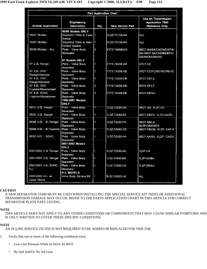
1999 Ford Truck Explorer 2WD V6-245 4.0L VIN X SFI Copyright © 2008, ALLDATA 9.90 Page 114
CAUTIONA NEW SEPARATOR 7Z490 MUST BE USED WHEN INSTALLING THE SPECIAL SERVICE KIT 7M203 OR ADDITIONALTRANSMISSION DAMAGE MAY OCCUR. REFER TO THE PARTS APPLICATION CHART IN THIS ARTICLE FOR CORRECTSEPARATOR PLATE PART LISTING.
NOTETHIS ARTICLE DOES NOT APPLY TO ANY OTHER CONDITIONS OR COMPONENTS THAT MAY CAUSE SIMILAR SYMPTOMS ANDIS ONLY WRITTEN TO COVER THESE SPECIFIC CONDITIONS.
NOTEAN IN-LINE SERVICE FILTER IS NOT REQUIRED TO BE ADDED OR REPLACED FOR THIS TSB.
1. Verify that one or more of the following conditions exist.
^ Low Line Pressure While In Drive At WOT
^ No 2nd And/Or No 3rd Gear
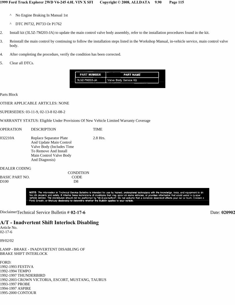
1999 Ford Truck Explorer 2WD V6-245 4.0L VIN X SFI Copyright © 2008, ALLDATA 9.90 Page 115
^ No Engine Braking In Manual 1st
^ DTC P0732, P0733 Or P1762
2. Install kit (3L5Z-7M203-JA) to update the main control valve body assembly, refer to the installation procedures found in the kit.
3. Reinstall the main control by continuing to follow the installation steps listed in the Workshop Manual, in-vehicle service, main control valvebody.
4. After completing the procedure, verify the condition has been corrected.
5. Clear all DTCs.
Parts Block
OTHER APPLICABLE ARTICLES: NONE
SUPERSEDES: 03-11-9, 02-13-8 02-08-2
WARRANTY STATUS: Eligible Under Provisions Of New Vehicle Limited Warranty Coverage
OPERATION DESCRIPTION TIME
032210A Replace Separator Plate 2.8 Hrs.And Update Main ControlValve Body (Includes TimeTo Remove And InstallMain Control Valve BodyAnd Diagnosis)
DEALER CODINGCONDITION
BASIC PART NO. CODED100 D8
DisclaimerTechnical Service Bulletin # 02-17-6 Date: 020902
A/T - Inadvertent Shift Interlock DisablingArticle No.02-17-6
09/02/02
LAMP - BRAKE - INADVERTENT DISABLING OF BRAKE SHIFT INTERLOCK
FORD:1992-1993 FESTIVA1992-1994 TEMPO1992-1997 THUNDERBIRD1992-2003 CROWN VICTORIA, ESCORT, MUSTANG, TAURUS1993-1997 PROBE1994-1997 ASPIRE1995-2000 CONTOUR
1999 Ford Truck Explorer 2WD V6-245 4.0L VIN X SFI Copyright © 2008, ALLDATA 9.90 Page 116
2002-2003 THUNDERBIRD1992-1997 AEROSTAR1992-2003 E SERIES1993-1997 F SUPER DUTY1994-1996 BRONCO1994-1997 F-250, F-3501994-2003 F-1501995-2003 EXPLORER, RANGER, WINDSTAR1997-2003 EXPEDITION1998-1999 F-250 LD1999-2003 SUPER DUTY F SERIES2000-2003 EXCURSION, EXPLORER SPORT2001-2003 ESCAPE, EXPLORER SPORT TRAC
LINCOLN:1992-2003 CONTINENTAL, TOWN CAR1993-1998 MARK VIII2000-2003 LS1998-2003 NAVIGATOR
MERCURY:1992-1994 TOPAZ1992-1997 COUGAR1992-1999 TRACER1992-2003 SABLE1993-2003 GRAND MARQUIS1994 CAPRI1995-2000 MYSTIQUE1999-2003 COUGAR1993-2002 VILLAGER1997-2003 MOUNTAINEER
Article 01-18-1 is being republished in its entirety to update the model year coverage and vehicle line applications.
ISSUE
Corporate, municipal, or police fleets may have had their Ford Motor Company vehicle modified to flash the brake lamps whenever the "police lights"or other aftermarket lights are turned on. These added "police lights" have the potential to disable the brake shift interlock system. The brake shiftinterlock feature prevents the vehicle from being shifted from park unless the brake pedal is depressed. Disabling of the brake shift interlock featuremay enable the operator to inadvertently apply the accelerator instead of the brake pedal when shifting from Park to Drive or Reverse gears.
ACTION
As appropriate, dealers should advise owners (including corporate, municipal, and police agencies) that any vehicle that has been modified with aconnection to the brake circuit, or that electrically interfaces with the brake lamps in that manner, should be disconnected IMMEDIATELY and theemergency lighting system should be modified in a manner that does not interfere with normal service operation or the brake shift interlock. In addition,if the high-mount stoplamp flashes when the "police lights" are on, the modification does not conform with the Federal Motor Vehicle Safety Standards(FMVSS) 108 which requires that the high-mount stoplamp only illuminate when applying the brakes.
Installation of warning lights should only be performed with a completely separate electrical system, without connection to any existing vehicle wiring.Connection of aftermarket electrical equipment into the brake lamp circuit or any other circuit which is connected to the Powertrain Control Module(PCM), anti-lock brake computer, air bag system, or any other vehicle system, will cause vehicle malfunction.
OTHER APPLICABLE ARTICLES: NONESUPERSEDES: 01-18-1WARRANTY STATUS: INFORMATION ONLYOASIS CODES: 203000, 203200, 205000, 301000, 503300Technical Service Bulletin # 99-16-10 Date: 990809
A/T - 4R44E/5R55E Slipping/Delayed Shift/No EngagementArticle No.99-16-10
08/09/99
TRANSMISSION - R44E OR 5R55E - SLIPPING SHIFT/DELAYED OR NO ENGAGEMENT
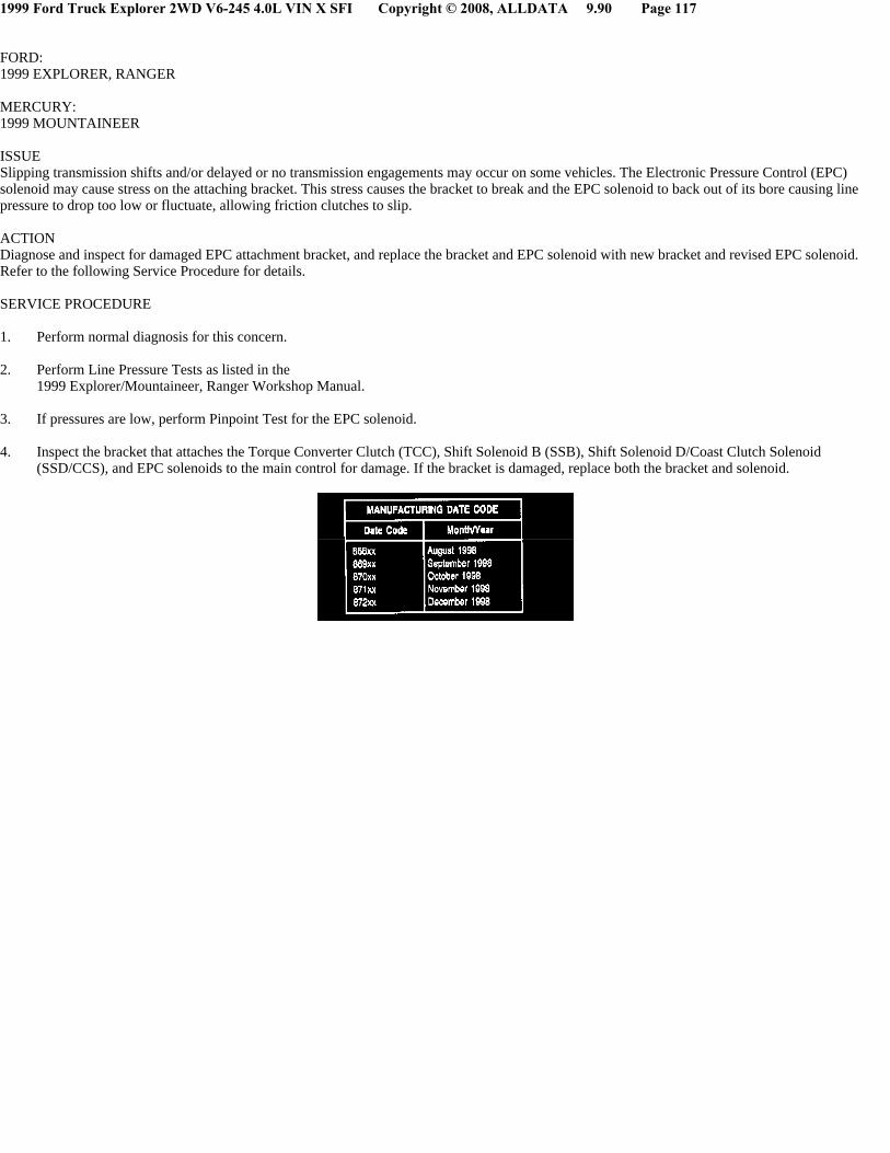
1999 Ford Truck Explorer 2WD V6-245 4.0L VIN X SFI Copyright © 2008, ALLDATA 9.90 Page 117
FORD: 1999 EXPLORER, RANGER
MERCURY: 1999 MOUNTAINEER
ISSUESlipping transmission shifts and/or delayed or no transmission engagements may occur on some vehicles. The Electronic Pressure Control (EPC)solenoid may cause stress on the attaching bracket. This stress causes the bracket to break and the EPC solenoid to back out of its bore causing linepressure to drop too low or fluctuate, allowing friction clutches to slip.
ACTIONDiagnose and inspect for damaged EPC attachment bracket, and replace the bracket and EPC solenoid with new bracket and revised EPC solenoid.Refer to the following Service Procedure for details.
SERVICE PROCEDURE
1. Perform normal diagnosis for this concern.
2. Perform Line Pressure Tests as listed in the1999 Explorer/Mountaineer, Ranger Workshop Manual.
3. If pressures are low, perform Pinpoint Test for the EPC solenoid.
4. Inspect the bracket that attaches the Torque Converter Clutch (TCC), Shift Solenoid B (SSB), Shift Solenoid D/Coast Clutch Solenoid(SSD/CCS), and EPC solenoids to the main control for damage. If the bracket is damaged, replace both the bracket and solenoid.

1999 Ford Truck Explorer 2WD V6-245 4.0L VIN X SFI Copyright © 2008, ALLDATA 9.90 Page 118
5. If the bracket is not damaged, inspect the solenoid for the affected date code (refer to the following Manufacturing Date Code Chart) and IDmarking (Figure 1, Views 1, 2, and 3). If the solenoid is one of the affected, replace it.
6. Inspect the fluid pan for major contamination.
^ If contamination is minimal, clean the main control, but do not replace.
^ If major contamination is present, perform normal transmission overhaul as required, including main control replacement. Pay particularattention to the condition of the friction plates. Repair as required.
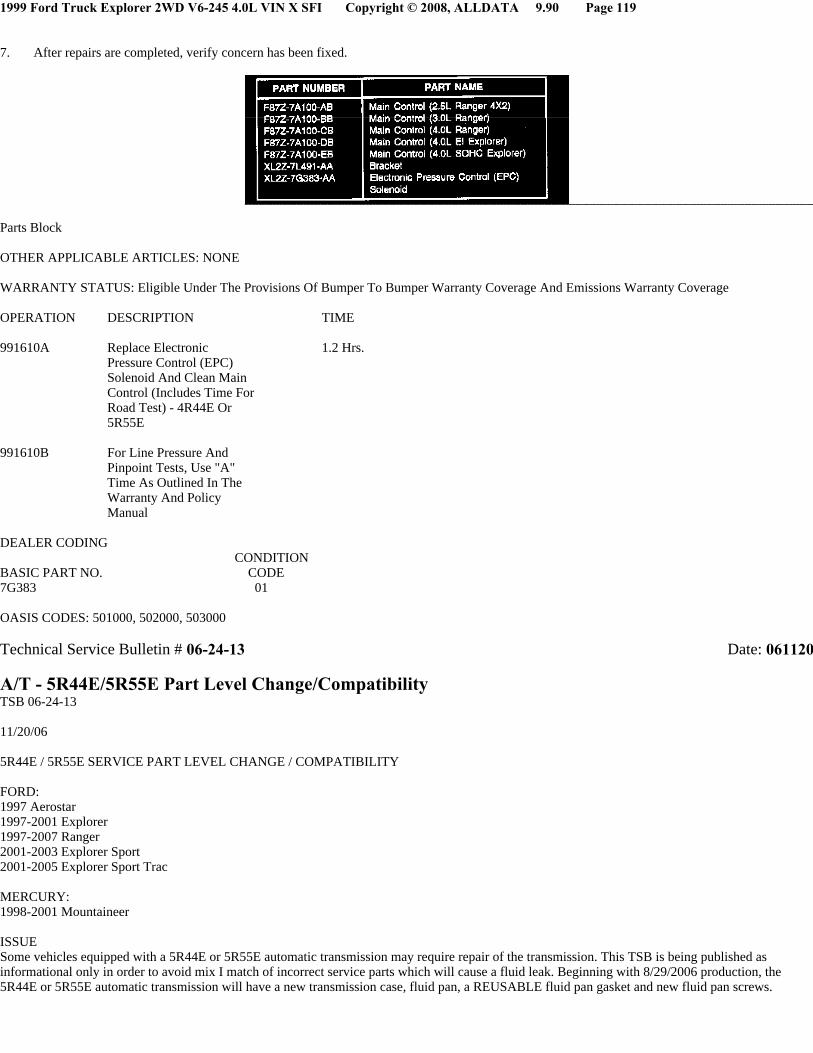
1999 Ford Truck Explorer 2WD V6-245 4.0L VIN X SFI Copyright © 2008, ALLDATA 9.90 Page 119
7. After repairs are completed, verify concern has been fixed.
Parts Block
OTHER APPLICABLE ARTICLES: NONE
WARRANTY STATUS: Eligible Under The Provisions Of Bumper To Bumper Warranty Coverage And Emissions Warranty Coverage
OPERATION DESCRIPTION TIME
991610A Replace Electronic 1.2 Hrs.Pressure Control (EPC)Solenoid And Clean MainControl (Includes Time ForRoad Test) - 4R44E Or5R55E
991610B For Line Pressure AndPinpoint Tests, Use "A"Time As Outlined In TheWarranty And PolicyManual
DEALER CODINGCONDITION
BASIC PART NO. CODE7G383 01
OASIS CODES: 501000, 502000, 503000
Technical Service Bulletin # 06-24-13 Date: 061120
A/T - 5R44E/5R55E Part Level Change/CompatibilityTSB 06-24-13
11/20/06
5R44E / 5R55E SERVICE PART LEVEL CHANGE / COMPATIBILITY
FORD:1997 Aerostar1997-2001 Explorer1997-2007 Ranger2001-2003 Explorer Sport2001-2005 Explorer Sport Trac
MERCURY:1998-2001 Mountaineer
ISSUESome vehicles equipped with a 5R44E or 5R55E automatic transmission may require repair of the transmission. This TSB is being published asinformational only in order to avoid mix I match of incorrect service parts which will cause a fluid leak. Beginning with 8/29/2006 production, the5R44E or 5R55E automatic transmission will have a new transmission case, fluid pan, a REUSABLE fluid pan gasket and new fluid pan screws.

1999 Ford Truck Explorer 2WD V6-245 4.0L VIN X SFI Copyright © 2008, ALLDATA 9.90 Page 120
ACTIONFollow the Service Tips.
SERVICE TIPS
NOTEDO NOT MIX AND MATCH PARTS OR LEAKAGE WILL OCCUR.
NOTETHE NEW PAN GASKET IS NOT INCLUDED IN THE GASKET AND SEAL KIT. IT CAN ONLY BE ORDERED SEPARATELY.
The 5R44E / 5R55E transmission pan gasket has been redesigned to be reusable if it is removed for a non-leak related transmission service concern.The gasket should be inspected for damage and cleaned, along with the mating surfaces, before reuse. The case and fluid pan rails have been redesignedto properly mate with the new gasket to eliminate fluid leaks. The new case, pan, and gasket maybe used to service past model transmissions from 1997.

1999 Ford Truck Explorer 2WD V6-245 4.0L VIN X SFI Copyright © 2008, ALLDATA 9.90 Page 121
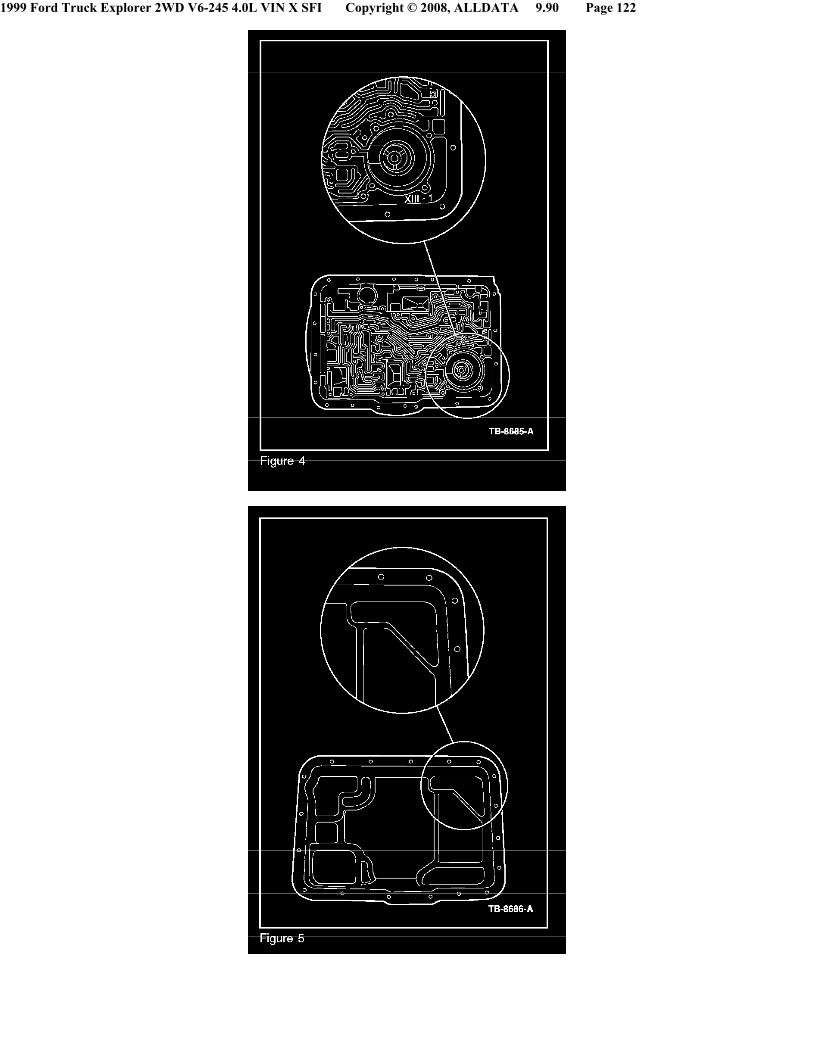
1999 Ford Truck Explorer 2WD V6-245 4.0L VIN X SFI Copyright © 2008, ALLDATA 9.90 Page 122

1999 Ford Truck Explorer 2WD V6-245 4.0L VIN X SFI Copyright © 2008, ALLDATA 9.90 Page 123
For 1997-2007 (early production) 4R44E I 5R44E and 5R55E when servicing the fluid pan gasket (7A191), the fluid pan (7A194) or the case (7005) donot mix and match old level and new level parts. The old level gasket, refer to Figure 3 (7A191) will be continued for past model applications. Ifreplacing the older design level case, refer to Figure 1 (7005) and/or old lever fluid pan, refer to Figure 2 (7A194), ALL new components must be used.This includes the case (7005), refer to Figure 4, fluid pan (7A194), refer to Figure 5, fluid pan gasket (7A191), refer to Figure 6 and pan screws(W500212) (new torque specification - 7 lb-ft (10 N.m) refer to Figure 7.
For correct part numbers refer to your parts catalogue.
WARRANTY STATUS: Information Only
Disclaimer