automation - wegecatalog.weg.net/files/wegnet/weg-power-factor-correction-5003384… · 4 power...
TRANSCRIPT

Automation Power Factor Correction
Motors | Automation | Energy | Transmission & Distribution | Coatings

www.weg.net
Power Factor Correction 2

www.weg.net
Power Factor Correction 3
Index
Products Series1)
Technical characteristicsStandards Certifications2)3) Pages
Power Rated voltageConnection
type
UCW series Single phase
Capacitive units
A0.62...0.83
(kvar)380...535 (V) -
IEC 60831-1/2 UL 810
06B0.62...6.67
(kvar)208...535 (V) -
IEC 60831-1/2 UL 810
C3.72...10.0
(kvar)208...535 (V) -
IEC 60831-1/2 UL 810
UCWT series Three phase
Capacitive units
D0.37...5.0
(kvar)208...535 (V)
∆ (Delta)
IEC 60831-1/2 UL 810
09E3.72...15.0
(kvar)208...535 (V)
∆ (Delta)
IEC 60831-1/2 UL 810
F7.48...50.0
(kvar)208...535 (V)
∆ (Delta)
IEC 60831-1/2 UL 810
4)5)
MCW series Three phase
Capacitor module-
1.85...15.0 (kvar)
208...535 (V)∆
(Delta) IEC 60831-1/2
UL 810
12
Accessories for capacitors
- - - - - - 27
CWMC Contators for switching of capacitors
- Up to 77 (kvar) Up to 690 (V) -IEC 60947-1
UL 508 29
Introduction to power factor correction 31
Notes: 1) For easier identification, the capacitors are sorted according to their mechanical and electrical characteristics (see page 6 to 11). 2) For additional information, contact WEG. 3) IRAM Certification available for capacitors of the following voltage/frequency: 230 V / 50 Hz, 400 V / 50 Hz, 440 V / 50 Hz e 480 V / 50 Hz. 4) in progress to capacitors 136 x 290 mm. 5) in progress to capacitors 116 x 290 mm and 136 x 290 mm.R
US
R
US
R
US
R
US
R
US
R
US
R
US
R
US

www.weg.net
Power Factor Correction 4
WEG has played an important role in the electric industry raising the quality and process bar to the highest level since it began the production of the most elementary switch and control gear devices for electric motors. As a result, WEG presents its series of Capacitors for Power Factor Correction, which are assembled according to national and international standards such as NBR IEC 60831 parts 1 and 2, EN IEC 60831 parts 1 and 2 and UL 810. WEG’s production chain also includes the ISO 9001 and 14001 certifications.
Capacitors: The Technology Within
During their useful life, the capacitors may be subjected to certain utilization conditions, such as electrical and thermal overloads (voltage surges, short circuits, harmonics, excessive switching, high ambient temperature), which can damage them prematurely.
Due to the utilization conditions mentioned above, WEG capacitors are assembled with a high performance and low loss self-healing polypropylene dielectric film providing two important characteristics:
J Low Watt losses: dielectric losses smaller than 0.2 W / kvar J Self-healing properties: in application conditions that cause a short circuit fault in the dielectric, the self-healing effect quickly reestablishes its electric properties
As shown in the picture below, obtained through microscopic magnification, when there is a fault in the dielectric, the metallic layer above the polypropylene film vaporizes around the rupture point isolating the short circuit. This happens because at the moment of short circuit, the metal layer around the fault is subjected to high temperatures. This is the self-healing effect.
Polypropylene Film After Self-Healing Effect
Rupture of dielectric area
Area where self-healing occurred (metal vaporization)
Isolated area, which increases distance between rupture area and conductive layer
Self-healing polypropylene film conductive layer
Rupture of dielectric area(magnified 1,000 times)

www.weg.net
Power Factor Correction 5
The reduction of the capacitance after the self-healing is so small that it can only be verified with precise measurements and the capacitor remains operating normally after each self-healing. The cumulative effect of the self-healing will result in the increase of its internal pressure up to the point of the end of its life.
To avoid possible damage to the electric installation caused by over-pressure in the capacitor, the polypropylene WEG capacitors are specially designed for power factor correction and have a safety system against internal over-pressures. This safety system has the function of interrupting the electric current on the capacit and when the internal pressure is too high. The actuation of this system normally occurs in the end of the life of the capacitor or in cases of overload conditions.
The aluminum enclosures used on WEG capacitors are made from a specific aluminum alloy assuring greater durability, better thermal dissipation and a perfect actuation of the safety system against over-pressure.
To protect the capacitive element from the influence of the external environment (humidity and other impurities), as well as assuring proper heat dissipation and a longer useful life to WEG capacitors, the capacitive element is mounted on the aluminum enclosure and filled with a special non-poisonous oil. WEG capacitors are PCB free.
The internal over-pressure caused by the cumulative of self-healing effect of the polypropylene film will create a force on the internal walls of the capacitor. This force will act on the expandable grooves (capacitive units with plastic closing top) or on the metallic cover resulting in the breaking of the “mechanical fuse” and, consequently, disconnecting the capacitor from the power source. This mechanism provides total protection against over-pressure.
WEG Safety System
WEG Safety System in Plastic Covers WEG Safety System in Metallic Covers
Breaking area(connected)
Breaking area(disconnected)
Expandable groove(expanded)
Expandable groove(normal)
Normal Expanded
Breaking area (connected)
Breaking area(disconected)
Detail A Detail B
Normal Expanded
Expansion of cover
Detail A Detail B
Max. 20 mm
WEG capacitors are certified in UL - Underwriters Laboratories INC. in the highest level of short-circuit current, according UL 810, ensuring safety, reliability and robustness.
R
US

www.weg.net
Power Factor Correction 6
A SeriesSingle Phase Capacitive Units - UCW
Power 0.62...0.83 (kvar)Rated Voltage 380...535 (V)
J Fast-on connection terminals for connection of power cables and discharge resistors
J Double fast-on allowing the connection of power cables separately from discharge resistors
J Grounding is assured by connection of capacitive unit fixing bolt with assembly plate
Electrical Connection
6.3
9.10
0.80
Note: 1) The grounding cable must be connected directly to the capacitor fixing screw or the capacitor must be fixed on a grounded base.
9.10
6.3
0.80
Mounting
Dimensional (mm) and Protection Degree
Diameter (Ø) Height (H) Protection degree Size code
40 85 IP00 G4
40 105 IP00 G6
M8 bolt fixing(nut and washer not included in UCW)1)
>20 mm
Horizontal mounting Vertical mounting
>20 mm
1613
.5H
M8
Ø

www.weg.net
Power Factor Correction 7
B SeriesSingle Phase Capacitive Units - UCW
Power 0.62...3.3 (kvar)Rated Voltage 208...240 (V)
Power 0.62...6.67 (kvar)Rated Voltage 380...535 (V)
Electrical Connection J M3 Flat/Philips screw terminals for connection of power cables J Fast-on connection terminals for discharge resistor connection J Allows connection of power cables separately from discharge resistors
J Grounding is assured by connection of capacitive unit fixing bolt with assembly plate
Note: 1) The grounding cable must be connected directly to the capacitor fixing screw or the capacitor must be fixed on a grounded base.
Mounting
Dimensional (mm) and Protection Degree
Diameter (Ø) Height (H) Protection degree Size code
53 68 IP00 J2
53 85 IP00 J4
53 105 IP00 J6
53 141 IP00 J8
60 85 IP00 L4
60 105 IP00 L6
60 141 IP00 L8
60 156 IP00 L10
70 156 IP00 M10
M12 bolt fixing(nut and washer not included in UCW)1)
>20 mm
Horizontal mounting Vertical mounting
>20 mm
1613
.5H
M12
Ø

www.weg.net
Power Factor Correction 8
C SeriesSingle Phase Capacitive Units - UCW
Power 3.72...6.67 (kvar)Rated Voltage 208...240 (V)
Power 5.56...10 (kvar)Rated Voltage 380...535 (V)
J “Box” type terminals for connection of power cables J Fast-on connection terminals for discharge resistor connection (discharge resistor included)
J Allows the connection of power cables separately from discharge resistors
J Grounding is assured by connection of capacitive unit fixing bolt with assembly plate
Electrical Connection
Note: 1) The grounding cable must be connected directly to the capacitor fixing screw or the capacitor must be fixed on a grounded base.
Diameter (Ø) Height (H) Protection degree Size code
75 205 IP20 N14
Dimensional (mm) and Protection Degree
Mounting
M12 bolt fixing(nut and washer included)1)
>20 mm
>20 mm
Vertical mounting
1645
H
Ø
M12

www.weg.net
Power Factor Correction 9
D SeriesThree Phase Capacitive Units - UCWT
Power 0.37...3 (kvar)Rated Voltage 208...240 (V)
Power 0.37...5 (kvar)Rated Voltage 380...535 (V)
Electrical Connections J Provided with IP50 protection cover J M3 Flat/Philips screw terminals for connection of power cables J Internal discharge resistor in capacitive cell J Grounding is assured by connection of capacitive unit fixing bolt with assembly plate
Note: 1) The grounding cable must be connected directly to the capacitor fixing screw or the capacitor must be fixed on a grounded base.
Mounting
Diameter (Ø) Height (H) Protection degree Size code
60 156 IP50 L10
60 211 IP50 L16
Dimensional (mm) and Protection Degree
M12 bolt fixing(nut and washer included)1)
>20 mm
Horizontal mounting Vertical mounting
>20 mmHØ
72
35
M12
16

www.weg.net
Power Factor Correction 10
E SeriesThree Phase Capacitive Units - UCWT
Power 3.72...10 (kvar)Rated Voltage 208...240 (V)
Power 5.56...15 (kvar)Rated Voltage 380...535 (V)
J “Box” type terminals for connection of power cablesJ Fast-on connection terminals for discharge resistor connectionJ Allows connection of power cables separately from discharge resistorsJ Grounding is assured by connection of capacitive unit fixing bolt with
assembly plate
Electrical Connections
Note: 1) The grounding cable must be connected directly to the capacitor fixing screw or the capacitor must be fixed on a grounded base.
Dimensional (mm) and Protection Degree
Mounting
16H
M12
Ø
45
Diameter (Ø) Height (H) Protection degree Size code
75 225 IP20 N20
75 285 IP20 N22
M12 bolt fixing(nut and washer included)1)
>20 mm
>20 mm
Vertical mounting

www.weg.net
Power Factor Correction 11
F SeriesThree Phase Capacitive Units - UCWT
Power 7.45...30 (kvar)Rated Voltage 208...240 (V)
Power 11.12...50 (kvar)Rated Voltage 380...535 (V)
J Flexible installation and connectionJ “Box” type terminals for connection of power cablesJ Fast-on connection terminals for discharge resistor connectionJ Allows connection of power cables separately from discharge resistorsJ Grounding is assured by connection of capacitive unit fixing bolt with
assembly plate
Electrical Connections
Note: 1) The grounding cable must be connected directly to the capacitor fixing screw or the capacitor must be fixed on a grounded base.
Power 7.45...15 (kvar)Rated voltage 208...240 (V)
Power 11.12...25 (kvar)Rated voltage 380...535 (V)
Power 17.5...30 (kvar)Rated voltage 208...240 (V)
Power 30...50 (kvar)Rated voltage 380...535 (V)
Dimensional (mm) and Protection Degree
Mounting
1645
H
Ø
M12
Diameter (Ø) Height (H) Protection degree Size code
100 230 IP20 Q26
116 230 IP20 S26
116 290 IP20 S28
136 290 IP20 U28
M12 bolt fixing(nut and washer included)1)
>20 mm
>20 mm
Vertical mounting

www.weg.net
Power Factor Correction 12
Three Phase Capacitive Module - MCW
Power 1.86...10 (kvar)Rated Voltage 208...240 (V)
Power 1.85...15 (kvar)Rated Voltage 380...535 (V)
Module Connection in Parallel J Voltage up to 240 V: It is possible to connect up to 3 MCW modules in parallel using connection BI-MCW bars. For voltages from 208 V to 240 V, it is possible to compensate up to 30 kvar.
J Voltage equal or higher than 380 V: It is possible to connect up to 4 MCW modules in parallel using BI-MCW bars. For voltages from 380 V to 535 V, it is possible to compensate up to 60 kvar.
Dimensional (mm) and Protection Degree
Mounting
H
L W
Number of modulesDimensions (L x W x H)
Protection degree
1 219 x 78 x 257 IP40
2 219 x 156 x 257 IP40
3 219 x 234 x 257 IP40
4 219 x 312 x 257 IP40
Module horizontal mounting
360o
Module vertical mounting

www.weg.net
Power Factor Correction 13
Single Phase Capacitive Units - UCW
Power 0.62...6.67 (kvar)Rated Voltage 208...240 (V)
Power 0.62...10 (kvar)Rated Voltage 380...535 (V)
Single phase capacitors - UCW1)
Rated voltage
(V)
50 Hz 60 HzCapacitance
(uF)Series2) Reference
Dimensions Ø x H (mm)
Discharge resistor3) CodeWeight
(kg)Reactive power (kvar)
Rated current In (A)4)
Reactive power (kvar)
Rated current In (A)4)
208
0.62 3.0 0.74 3.6 45.5 B UCW0.83V25 J4 53 x 85 Not Included 270kΩ/3W 11488457 0.27
0.62 3.0 0.74 3.6 45.5 B UCW0.83V25 L6 60 x 105 Not Included 270kΩ/3W 10045809 0.34
1.24 6.0 1.49 7.2 91.5 B UCW1.67V25 L6 60 x 105 Not Included 150kΩ/3W 10045802 0.35
1.86 9.0 2.23 10.7 137.0 B UCW2.5V25 L10 60 x 156 Not Included 82kΩ/3W 10045950 0.51
2.48 11.9 2.98 14.3 182.5 B UCW3.33V25 L10 60 x 156 Not Included 56kΩ/3W 10046652 0.51
3.72 17.9 4.47 21.5 274.0 C UCW5V25 N14 75 x 205 Included 41kΩ/6W 11449885 1.19
4.97 23.9 5.96 28.7 365.6 C UCW6.67V25 N14 75 x 205 Included 28kΩ/6W 11507565 1.22
220
0.69 3.1 0.83 3.8 45.5 B UCW0.83V25 J4 53 x 85 Not Included 270kΩ/3W 11488457 0.27
0.69 3.1 0.83 3.8 45.5 B UCW0.83V25 L6 60 x 105 Not Included 270kΩ/3W 10045809 0.34
1.39 6.3 1.67 7.6 91.5 B UCW1.67V25 L6 60 x 105 Not Included 150kΩ/3W 10045802 0.35
2.08 9.5 2.50 11.4 137.0 B UCW2.5V25 L10 60 x 156 Not Included 82kΩ/3W 10045950 0.51
2.78 12.6 3.33 15.1 182.5 B UCW3.33V25 L10 60 x 156 Not Included 56kΩ/3W 10046652 0.51
4.17 18.9 5.00 22.7 274.0 C UCW5V25 N14 75 x 205 Included 41kΩ/6W 11449885 1.19
5.56 25.3 6.67 30.3 365.6 C UCW6.67V25 N14 75 x 205 Included 28kΩ/6W 11507565 1.22
230
0.83 3.6 1.00 4.3 49.9 B UCW0.83V34 L6 60 x 105 Not Included 180kΩ/3W 10072341 0.32
1.67 7.3 2.00 8.7 100.5 B UCW1.67V34 L8 60 x 141 Not Included 120kΩ/3W 10046044 0.44
2.50 10.9 3.00 13.0 150.4 B UCW2.5V34 L10 60 x 156 Not Included 56kΩ/3W 10046045 0.51
3.33 14.5 4.00 17.4 200.4 B UCW3.33V34 L10 60 x 156 Not Included 56kΩ/3W 11559336 0.50
5.00 21.7 6.00 26.1 300.9 C UCW5V34 N14 75 x 205 Included 28kΩ/6W 11507589 1.18
240
0.69 2.9 0.83 3.5 38.2 B UCW0.83V29 L6 60 x 105 Not Included 270kΩ/3W 10048213 0.36
1.39 5.8 1.67 7.0 76.9 B UCW1.67V29 L6 60 x 105 Not Included 150kΩ/3W 10048211 0.33
2.08 8.7 2.50 10.4 115.1 B UCW2.5V29 L8 60 x 141 Not Included 82kΩ/3W 10045988 0.45
2.78 11.6 3.33 13.9 153.4 B UCW3.33V29 L10 60 x 156 Not Included 82kΩ/3W 10076158 0.51
4.17 17.4 5.00 20.8 230.3 C UCW5V29 N14 75 x 205 Included 60kΩ/6W 12573706 1.18
380
0.69 1.8 0.83 2.2 15.2 A UCW0.83V40 G4 40 x 85 Not Included 560kΩ/3W 11509005 0.19
0.69 1.8 0.83 2.2 15.2 B UCW0.83V40 J2 53 x 68 Not Included 560kΩ/3W 11488508 0.23
1.39 3.7 1.67 4.4 30.7 B UCW1.67V40 J4 53 x 85 Not Included 390kΩ/3W 11488510 0.28
2.08 5.5 2.50 6.6 45.9 B UCW2.5V40 J6 53 x 105 Not Included 270kΩ/3W 13497628 0.22
2.78 7.3 3.33 8.8 61.2 B UCW3.33V40 J8 53 x 141 Not Included 150kΩ/3W 11488809 0.43
4.17 11.0 5.00 13.2 91.8 B UCW5V40 L10 60 x 156 Not Included 120kΩ/3W 10045951 0.52
5.56 14.6 6.67 17.6 122.5 B UCW6.67V40 M10 70 x 156 Not Included 82kΩ/3W 10630797 0.60
6.25 16.4 7.5 19.7 137.8 C UCW7.5V40 N14 75 x 205 Included 75kΩ/6W 11449886 1.19
6.94 18.3 8.33 21.9 153.0 C UCW8.33V40 N14 75 x 205 Included 60kΩ/6W 11449950 1.18
7.64 20.1 9.17 24.1 168.5 C UCW9.17V40 N14 75 x 205 Included 60kΩ/6W 11449951 1.23
8.33 21.9 10.00 26.3 183.7 C UCW10V40 N14 75 x 205 Included 60kΩ/6W 11449887 1.23
Notes: 1) For other voltages, please contact WEG. 2) Nuts and washers provided as standard for C series capacitors only. For A and B series - sold separately. 3) Discharge resistors sized so the voltage on the terminals of the capacitor is 1/10 of the rated voltage in 30s. 4) Calculated for single-phase systems.

www.weg.net
Power Factor Correction 14
Single Phase Capacitive Units - UCW
Power 0.62...6.67 (kvar)Rated Voltage 208...240 (V)
Power 0.62...10 (kvar)Rated Voltage 380...535 (V)
Single phase capacitors - UCW1)
Rated voltage
(V)
50 Hz 60 HzCapacitance
(uF)Series2) Reference
Dimensions Ø x H (mm)
Discharge resistor3) CodeWeight
(kg)Reactive power (kvar)
Rated current In (A)4)
Reactive power (kvar)
Rated current In (A)4)
400
0.83 2.1 - - 16.5 A UCW0.83V44 G6 40 x 105 Not Included 560kΩ/3W 11509029 0.22
0.83 2.1 1.00 2.5 16.5 B UCW0.83V44 J2 53 x 68 Not Included 560kΩ/3W 11488815 0.23
0.83 2.1 1.00 2.5 16.5 B UCW0.83V44 L4 60 x 85 Not Included 560kΩ/3W 10072342 0.32
1.67 4.2 2.00 5.0 33.2 B UCW1.67V44 J6 53 x 105 Not Included 270kΩ/3W 11488820 0.33
1.67 4.2 2.00 5.0 33.2 B UCW1.67V44 L4 60 x 85 Not Included 270kΩ/3W 10046046 0.29
2.50 6.3 3.00 7.5 49.7 B UCW2.5V44 J8 53 x 141 Not Included 180kΩ/3W 11488822 0.43
2.50 6.3 3.00 7.5 49.7 B UCW2.5V44 L6 60 x 105 Not Included 180kΩ/3W 10046047 0.35
3.33 8.3 4.00 10.0 66.2 B UCW3.33V44 L8 60 x 141 Not Included 150kΩ/3W 10046048 0.47
5.00 12.5 - - 99.5 B UCW5V44 L10 60 x 156 Not Included 120kΩ/3W 10046049 0.51
6.67 16.7 - - 132.7 B UCW6.67V44 M10 70 x 156 Not Included 82kΩ/3W 10872824 0.55
7.50 18.8 9.00 22.5 149.2 C UCW7.5V44 N14 75 x 205 Included 75kΩ/6W 11507590 1.18
8.33 20.8 10.00 25.0 165.7 C UCW8.33V44 N14 75 x 205 Included 60kΩ/6W 11507591 1.21
9.17 22.9 - - 182.4 C UCW9.17V44 N14 75 x 205 Included 60kΩ/6W 11507593 1.23
415
0.62 1.5 0.74 1.8 11.4 A UCW0.83V49 G4 40 x 85 Not Included 1MΩ/3W 11509007 0.19
0.62 1.5 0.74 1.8 11.4 B UCW0.83V49 J2 53 x 68 Not Included 1MΩ/3W 11488824 0.23
0.74 1.8 0.89 2.1 13.6 B UCW0.83V48 L4 60 x 85 Not Included 560kΩ/3W 10072343 0.30
1.24 3.0 1.49 3.6 22.9 B UCW1.67V49 J4 53 x 85 Not Included 560kΩ/3W 11488825 0.28
1.49 3.6 1.78 4.3 27.5 B UCW1.67V48 L4 60 x 85 Not Included 390kΩ/3W 10046050 0.29
1.85 4.5 2.22 5.4 34.3 B UCW2.5V49 J6 53 x 105 Not Included 390kΩ/3W 13497629 0.22
2.22 5.4 2.67 6.4 41.1 B UCW2.5V48 L6 60 x 105 Not Included 270kΩ/3W 10072344 0.35
2.47 5.9 2.96 7.1 45.6 B UCW3.33V49 J8 53 x 141 Not Included 270kΩ/3W 11488827 0.45
2.96 7.1 3.55 8.6 54.8 B UCW3.33V48 L8 60 x 141 Not Included 180kΩ/3W 10046051 0.47
3.71 8.9 4.45 10.7 68.5 B UCW5V49 L10 60 x 156 Not Included 150kΩ/3W 10186125 0.55
4.45 10.7 - - 82.2 B UCW5V48 L10 60 x 156 Not Included 120kΩ/3W 10046722 0.53
4.94 11.9 5.93 14.3 91.4 B UCW6.67V49 M10 70 x 156 Not Included 120kΩ/3W 10630798 0.58
5.56 13.4 6.67 16.1 102.8 C UCW7.5V49 N14 75 x 205 Included 75kΩ/6W 11449911 1.17
6.18 14.9 7.41 17.9 114.1 C UCW8.33V49 N14 75 x 205 Included 75kΩ/6W 11449952 1.18
6.80 16.4 8.16 19.7 125.6 C UCW9.17V49 N14 75 x 205 Included 75kΩ/6W 11449953 1.21
7.41 17.9 8.90 21.4 137.0 C UCW10V49 N14 75 x 205 Included 75kΩ/6W 11449915 1.23
Notes: 1) For other voltages, please contact WEG. 2) Nuts and washers provided as standard for C series capacitors only. For A and B series - sold separately. 3) Discharge resistors sized so the voltage on the terminals of the capacitor is 1/10 of the rated voltage in 30s. 4) Calculated for single-phase systems.

www.weg.net
Power Factor Correction 15
Single Phase Capacitive Units - UCW
Power 0.62...6.67 (kvar)Rated Voltage 208...240 (V)
Power 0.62...10 (kvar)Rated Voltage 380...535 (V)
Single phase capacitors - UCW1)
Rated voltage
(V)
50 Hz 60 HzCapacitance
(uF)Series2) Reference
Dimensions Ø x H (mm)
Discharge resistor3) CodeWeight
(kg)Reactive power (kvar)
Rated current In (A)4)
Reactive power (kvar)
Rated current In (A)4)
440
0.69 1.6 0.83 1.9 11.4 A UCW0.83V49 G4 40 x 85 Not Included 1MΩ/3W 11509007 0.190.69 1.6 0.83 1.9 11.4 B UCW0.83V49 J2 53 x 68 Not Included 1MΩ/3W 11488824 0.230.83 1.9 1.00 2.3 13.6 B UCW0.83V48 L4 60 x 85 Not Included 560kΩ/3W 10072343 0.301.39 3.2 1.67 3.8 22.9 B UCW1.67V49 J4 53 x 85 Not Included 560kΩ/3W 11488825 0.281.67 3.8 2.00 4.6 27.5 B UCW1.67V48 L4 60 x 85 Not Included 390kΩ/3W 10046050 0.292.08 4.7 2.50 5.7 34.3 B UCW2.5V49 J6 53 x 105 Not Included 390kΩ/3W 13497629 0.222.50 5.7 3.00 6.8 41.1 B UCW2.5V48 L6 60 x 105 Not Included 270kΩ/3W 10072344 0.352.78 6.3 3.33 7.6 45.6 B UCW3.33V49 J8 53 x 141 Not Included 270kΩ/3W 11488827 0.453.33 7.6 4.00 9.1 54.8 B UCW3.33V48 L8 60 x 141 Not Included 180kΩ/3W 10046051 0.474.17 9.5 5.00 11.4 68.5 B UCW5V49 L10 60 x 156 Not Included 150kΩ/3W 10186125 0.555.00 11.4 - - 82.2 B UCW5V48 L10 60 x 156 Not Included 120kΩ/3W 10046722 0.535.56 12.6 6.67 15.2 91.4 B UCW6.67V49 M10 70 x 156 Not Included 120kΩ/3W 10630798 0.586.25 14.2 7.5 17.0 102.8 C UCW7.5V49 N14 75 x 205 Included 75kΩ/6W 11449911 1.176.94 15.8 8.33 18.9 114.1 C UCW8.33V49 N14 75 x 205 Included 75kΩ/6W 11449952 1.187.64 17.4 9.17 20.8 125.6 C UCW9.17V49 N14 75 x 205 Included 75kΩ/6W 11449953 1.218.33 18.9 10.00 22.7 137.0 C UCW10V49 N14 75 x 205 Included 75kΩ/6W 11449915 1.23
480
0.69 1.4 0.83 1.7 9.6 A UCW0.83V53 G4 40 x 85 Not Included 1MΩ/3W 11509028 0.190.69 1.4 0.83 1.7 9.6 B UCW0.83V53 J2 53 x 68 Not Included 1MΩ/3W 11488839 0.230.83 1.7 1.00 2.1 11.5 B UCW0.83V52 L6 60 x 105 Not Included 560kΩ/3W 10072476 0.341.39 2.9 1.67 3.5 19.2 B UCW1.67V53 J6 53 x 105 Not Included 560kΩ/3W 11488841 0.331.67 3.5 2.00 4.2 23.1 B UCW1.67V52 L6 60 x 105 Not Included 390kΩ/3W 10072477 0.342.08 4.3 2.50 5.2 28.8 B UCW2.5V53 J6 53 x 105 Not Included 390kΩ/3W 13497630 0.222.50 5.2 3.00 6.3 34.5 B UCW2.5V52 L6 60 x 105 Not Included 270kΩ/3W 10072345 0.342.78 5.8 3.33 6.9 38.3 B UCW3.33V53 J8 53 x 141 Not Included 270kΩ/3W 11488845 0.453.33 6.9 4.00 8.3 46.0 B UCW3.33V52 L8 60 x 141 Not Included 180kΩ/3W 10046053 0.444.17 8.7 5.00 10.4 57.6 B UCW5V53 L10 60 x 156 Not Included 180kΩ/3W 10045952 0.52
5.00 10.4 - - 69.1 B UCW5V52 L10 60 x 156 Not Included 150kΩ/3W 10046255 0.54
5.56 11.6 6.67 13.9 76.8 B UCW6.67V53 M10 70 x 156 Not Included 150kΩ/3W 10630800 0.576.25 13.0 7.50 15.6 86.3 C UCW7.5V53 N14 75 x 205 Included 135kΩ/6W 11449916 1.196.94 14.5 8.33 17.4 95.9 C UCW8.33V53 N14 75 x 205 Included 75kΩ/6W 11449954 1.187.64 15.9 9.17 19.1 105.6 C UCW9.17V53 N14 75 x 205 Included 75kΩ/6W 11449955 1.238.33 17.4 10.00 20.8 115.1 C UCW10V53 N14 75 x 205 Included 75kΩ/6W 11449928 1.22
535
0.69 1.3 0.83 1.6 7.7 B UCW0.83V57 L6 60 x 105 Not Included 1MΩ/3W 10046599 0.301.39 2.6 1.67 3.1 15.5 B UCW1.67V57 L6 60 x 105 Not Included 560kΩ/3W 10046600 0.302.08 3.9 2.50 4.7 23.2 B UCW2.5V57 L6 60 x 105 Not Included 390kΩ/3W 10046215 0.332.78 5.2 3.33 6.2 30.9 B UCW3.33V57 L6 60 x 105 Not Included 270kΩ/3W 10046362 0.344.17 7.8 5.00 9.3 46.3 B UCW5V57 L10 60 x 156 Not Included 180kΩ/3W 10045866 0.515.56 10.4 6.67 12.5 61.8 C UCW6.67V57 N14 75 x 205 Included 135kΩ/6W 11449929 1.186.25 11.7 7.50 14.0 69.5 C UCW7.5V57 N14 75 x 205 Included 135kΩ/6W 11449930 1.196.94 13.0 8.33 15.6 77.2 C UCW8.33V57 N14 75 x 205 Included 135kΩ/6W 11449957 1.187.64 14.3 9.17 17.1 85.0 C UCW9.17V57 N14 75 x 205 Included 135kΩ/6W 11449959 1.238.33 15.6 10.00 18.7 92.7 C UCW10V57 N14 75 x 205 Included 75kΩ/6W 11449931 1.22
Notes: 1) For other voltages, please contact WEG. 2) Nuts and washers provided as standard for C series capacitors only. For A and B series - sold separately. 3) Discharge resistors sized so the voltage on the terminals of the capacitor is 1/10 of the rated voltage in 30s. 4) Calculated for single-phase systems.

www.weg.net
Power Factor Correction 16
Three Phase Capacitive Units - UCWT
Three phase capacitors - UCWT1)2)
Ratedvoltage1)
(V)
50 Hz 60 Hz
Capacitance (uF)
Series3) ReferenceDimensions Ø x H (mm)
Discharge resistor2) Code
Weight (kg)
Reactive power (kvar)
Rated current In (A)
Reactive power (kvar)
Rated current In (A)
208
0.37 1.0 0.45 1.2 9.1 x 3 D UCWT0.5V25 L10 60 x 156 Internal resistor 10045998 0.51
0.56 1.6 0.67 1.9 13.7 x 3 D UCWT0.75V25 L10 60 x 156 Internal resistor 10045999 0.52
0.74 2.1 0.89 2.5 18.3 x 3 D UCWT1V25 L10 60 x 156 Internal resistor 10046000 0.54
1.12 3.1 1.34 3.7 27.4 x 3 D UCWT1.5V25 L10 60 x 156 Internal resistor 10046001 0.57
1.49 4.1 1.79 5.0 36.5 x 3 D UCWT2V25 L10 60 x 156 Internal resistor 10046002 0.59
1.86 5.2 2.23 6.2 45.7 x 3 D UCWT2.5V25 L16 60 x 211 Internal resistor 10046003 0.73
2.23 6.2 2.68 7.4 54.8 x 3 D UCWT3V25 L16 60 x 211 Internal resistor 10046004 0.76
3.72 10.3 4.47 12.4 91.3 x 3 E UCWT5V25 N20 75 x 225 3 x 120kΩ/3W 11313760 1.51
5.59 15.5 6.70 18.6 137 x 3 E UCWT7.5V25 N22 75 x 285 3 x 56kΩ/3W 11313783 1.81
7.45 20.7 8.94 24.8 182.7 x 3 E UCWT10V25 N22 75 x 285 3 x 56kΩ/3W 11313782 1.81
7.45 20.7 8.94 24.8 182.7 x 3 F UCWT10V25 Q26 100 x 230 3 x 56kΩ/3W 11914849 2.17
9.31 25.8 11.17 31.0 228.4 x 3 F UCWT12.5V25 Q26 100 x 230 3 x 56kΩ/3W 11914851 2.17
11.17 31.0 13.41 37.2 274 x 3 F UCWT15V25 S26 116 x 230 3 x 39kΩ/3W 11914853 2.69
13.04 36.2 15.64 43.4 319.7 x 3 F UCWT17.5V25 S28 116 x 290 3 x 27kΩ/5W 12271622 3.50
14.90 41.4 17.88 49.6 365.4 x 3 F UCWT20V25 S28 116 x 290 3 x 27kΩ/5W 12271626 3.50
18.62 51.7 22.35 62.0 456.7 x 3 F UCWT25V25 U28 136 x 290 3 x 82kΩ/3W 13365111 4.43
22.35 62.0 26.82 74.4 548.1 x 3 F UCWT30V25 U28 136 x 290 3 x 82kΩ/3W 13365631 4.43
220
0.42 1.1 0.50 1.3 9.1 x 3 D UCWT0.5V25 L10 60 x 156 Internal resistor 10045998 0.51
0.63 1.6 0.75 2.0 13.7 x 3 D UCWT0.75V25 L10 60 x 156 Internal resistor 10045999 0.52
0.83 2.2 1.00 2.6 18.3 x 3 D UCWT1V25 L10 60 x 156 Internal resistor 10046000 0.54
1.25 3.3 1.50 3.9 27.4 x 3 D UCWT1.5V25 L10 60 x 156 Internal resistor 10046001 0.57
1.67 4.4 2.00 5.2 36.5 x 3 D UCWT2V25 L10 60 x 156 Internal resistor 10046002 0.59
2.08 5.5 2.50 6.6 45.7 x 3 D UCWT2.5V25 L16 60 x 211 Internal resistor 10046003 0.73
2.50 6.6 3.00 7.9 54.8 x 3 D UCWT3V25 L16 60 x 211 Internal resistor 10046004 0.76
4.17 10.9 5.00 13.1 91.3 x 3 E UCWT5V25 N20 75 x 225 3 x 120kΩ/3W 11313760 1.51
6.25 16.4 7.50 19.7 137 x 3 E UCWT7.5V25 N22 75 x 285 3 x 56kΩ/3W 11313783 1.81
8.33 21.9 10.00 26.2 182.7 x 3 E UCWT10V25 N22 75 x 285 3 x 56kΩ/3W 11313782 1.81
8.33 21.9 10.00 26.2 182.7 x 3 F UCWT10V25 Q26 100 x 230 3 x 56kΩ/3W 11914849 2.17
10.42 27.3 12.50 32.8 228.4 x 3 F UCWT12.5V25 Q26 100 x 230 3 x 56kΩ/3W 11914851 2.17
12.50 32.8 15.00 39.4 274 x 3 F UCWT15V25 S26 116 x 230 3 x 39kΩ/3W 11914853 2.69
14.58 38.3 17.50 45.9 319.7 x 3 F UCWT17.5V25 S28 116 x 290 3 x 27kΩ/5W 12271622 3.50
16.67 43.7 20.00 52.5 365.4 x 3 F UCWT20V25 S28 116 x 290 3 x 27kΩ/5W 12271626 3.50
20.83 54.7 25.00 65.6 456.7 x 3 F UCWT25V25 U28 136 x 290 3 x 82kΩ/3W 13365111 4.43
25.00 65.6 30.00 78.7 548.1 x 3 F UCWT30V25 U28 136 x 290 3 x 82kΩ/3W 13365631 4.43
Power 0.37...30 (kvar)Rated Voltage 208...240 (V)
Power 0.37...50 (kvar)Rated Voltage 380...535 (V)
Notes: 1) For other voltages, please contact WEG. 2) Discharge resistors sized so that the voltage at the terminals of the capacitor is 1/10 of the rated voltage in 30s.
For powers higher than 20 kvar @ 220, 230, 240 V and 35 kvar @ 380, 400, 440, 480 and 535 V the discharge resistor is dimensioned so that the voltage at the capacitor terminals becomes 1/10 of the rated voltage in 120s.
3) The D series capacitors are provided with internal resistors in capacitive cell. The E and F series capacitors are provided with external resistors in the capacitive cell.

www.weg.net
Power Factor Correction 17
Three Phase Capacitive Units - UCWT
Three phase capacitors - UCWT1)2)
Ratedvoltage1)
(V)
50 Hz 60 Hz
Capacitance (uF)
Series3) ReferenceDimensions Ø x H (mm)
Discharge resistor2) Code
Weight (kg)
Reactive power (kvar)
Rated current In (A)
Reactive power (kvar)
Rated current In (A)
230
0.50 1.3 0.60 1.5 10 x 3 D UCWT0.5V34 L10 60 x 156 Internal resistor 10862201 0.46
0.75 1.9 0.90 2.3 15 x 3 D UCWT0.75V34 L10 60 x 156 Internal resistor 10072544 0.53
1.00 2.5 1.20 3.0 20.1 x 3 D UCWT1V34 L10 60 x 156 Internal resistor 10074467 0.55
1.50 3.8 1.80 4.5 30.1 x 3 D UCWT1.5V34 L10 60 x 156 Internal resistor 10862180 0.42
2.00 5.0 2.40 6.0 40.1 x 3 D UCWT2V34 L10 60 x 156 Internal resistor 10862184 0.54
2.50 6.3 3.00 7.5 50.1 x 3 D UCWT2.5V34 L16 60 x 211 Internal resistor 10072346 0.74
3.00 7.5 - - 60.2 x 3 D UCWT3V34 L16 60 x 211 Internal resistor 10046055 0.76
5.00 12.6 6.00 15.1 100.3 x 3 E UCWT5V34 N20 75 x 225 3 x 82kΩ/3W 11871789 1.56
7.50 18.8 9.00 22.6 150.4 x 3 E UCWT7.5V34 N22 75 x 285 3 x 56kΩ/3W 11758922 1.80
10.00 25.1 12.00 30.1 200.6 x 3 F UCWT10V34 Q26 100 x 230 3 x 56kΩ/3W 11914855 2.18
12.50 31.4 15.00 37.7 250.7 x 3 F UCWT12.5V34 Q26 100 x 230 3 x 39kΩ/3W 11914856 2.18
15.00 37.7 - - 300.9 x 3 F UCWT15V34 S26 116 x 230 3 x 39kΩ/3W 11914888 2.70
17.50 43.9 - - 351 x 3 F UCWT17.5V34 S28 116 x 290 3 x 27kΩ/5W 12271566 3.50
20.00 50.2 - - 401.1 x 3 F UCWT20V34 S28 116 x 290 3 x 27kΩ/5W 12271567 3.50
240
0.42 1.0 0.50 1.2 7.7 x 3 D UCWT0.5V29 L10 60 x 156 Internal resistor 10072607 0.50
0.63 1.5 0.75 1.8 11.5 x 3 D UCWT0.75V29 L10 60 x 156 Internal resistor 10072608 0.51
0.83 2.0 1.00 2.4 15.4 x 3 D UCWT1V29 L10 60 x 156 Internal resistor 10046265 0.52
1.25 3.0 1.50 3.6 23 x 3 D UCWT1.5V29 L10 60 x 156 Internal resistor 10072303 0.56
1.67 4.0 2.00 4.8 30.7 x 3 D UCWT2V29 L10 60 x 156 Internal resistor 10046266 0.56
2.08 5.0 2.50 6.0 38.4 x 3 D UCWT2.5V29 L16 60 x 211 Internal resistor 10748190 0.73
2.50 6.0 3.00 7.2 46.1 x 3 D UCWT3V29 L16 60 x 211 Internal resistor 10748194 0.74
4.17 10.0 5.00 12.0 76.8 x 3 E UCWT5V29 N20 75 x 225 3 x 120kΩ/3W 11983248 1.62
6.25 15.0 7.50 18.0 115.1 x 3 E UCWT7.5V29 N22 75 x 285 3 x 82kΩ/3W 11758813 1.87
8.33 20.0 10.00 24.1 153.5 x 3 E UCWT10V29 N22 75 x 285 3 x 56kΩ/3W 11758287 1.80
8.33 20.0 10.00 24.1 153.5 x 3 F UCWT10V29 Q26 100 x 230 3 x 56kΩ/3W 12029202 2.17
10.42 25.1 12.50 30.1 191.9 x 3 F UCWT12.5V29 Q26 100 x 230 3 x 56kΩ/3W 12029203 2.17
12.50 30.1 15.00 36.1 230.3 x 3 F UCWT15V29 S26 116 x 230 3 x 39kΩ/3W 12029204 2.72
14.58 35.1 17.50 42.1 268.6 x 3 F UCWT17.5V29 S28 116 x 290 3 x 27kΩ/5W 12271869 3.51
16.67 40.1 20.00 48.1 307 x 3 F UCWT20V29 S28 116 x 290 3 x 27kΩ/5W 12272006 3.50
Power 0.37...30 (kvar)Rated Voltage 208...240 (V)
Power 0.37...50 (kvar)Rated Voltage 380...535 (V)
Notes: 1) For other voltages, please contact WEG. 2) Discharge resistors sized so that the voltage at the terminals of the capacitor is 1/10 of the rated voltage in 30s.
For powers higher than 20 kvar @ 220, 230, 240 V and 35 kvar @ 380, 400, 440, 480 and 535 V the discharge resistor is dimensioned so that the voltage at the capacitor terminals becomes 1/10 of the rated voltage in 120s.
3) The D series capacitors are provided with internal resistors in capacitive cell. The E and F series capacitors are provided with external resistors in the capacitive cell.

www.weg.net
Power Factor Correction 18
Three Phase Capacitive Units - UCWT
Three phase capacitors - UCWT1)2)
Ratedvoltage1)
(V)
50 Hz 60 Hz
Capacitance (uF)
Series3) ReferenceDimensions Ø x H (mm)
Discharge resistor2) Code
Weight (kg)
Reactive power (kvar)
Rated current In (A)
Reactive power (kvar)
Rated current In (A)
380
0.42 0.6 0.50 0.8 3.1 x 3 D UCWT0.5V40 L10 60 x 156 Internal resistor 10046005 0.500.63 0.9 0.75 1.1 4.6 x 3 D UCWT0.75V40 L10 60 x 156 Internal resistor 10046006 0.510.83 1.3 1.00 1.5 6.1 x 3 D UCWT1V40 L10 60 x 156 Internal resistor 10046007 0.511.25 1.9 1.50 2.3 9.2 x 3 D UCWT1.5V40 L10 60 x 156 Internal resistor 10046008 0.531.67 2.5 2.00 3.0 12.2 x 3 D UCWT2V40 L10 60 x 156 Internal resistor 10046009 0.552.08 3.2 2.50 3.8 15.3 x 3 D UCWT2.5V40 L10 60 x 156 Internal resistor 10046010 0.612.50 3.8 3.00 4.6 18.4 x 3 D UCWT3V40 L10 60 x 156 Internal resistor 10046011 0.564.17 6.3 5.00 7.6 30.6 x 3 D UCWT5V40 L16 60 x 211 Internal resistor 10046012 0.746.25 9.5 7.50 11.4 45.9 x 3 E UCWT7.5V40 N20 75 x 225 3 x 180kΩ/3W 11313784 1.508.33 12.7 10.00 15.2 61.2 x 3 E UCWT10V40 N20 75 x 225 3 x 150kΩ/3W 11313787 1.5510.42 15.8 12.50 19.0 76.5 x 3 E UCWT12.5V40 N22 75 x 285 3 x 120kΩ/3W 11313820 1.8012.50 19.0 15.00 22.8 91.8 x 3 E UCWT15V40 N22 75 x 285 3 x 120kΩ/3W 11313821 1.8112.50 19.0 15.00 22.8 91.8 x 3 F UCWT15V40 Q26 100 x 230 3 x 120kΩ/3W 11916878 2.1714.58 22.2 17.50 26.6 107.2 x 3 F UCWT17.5V40 Q26 100 x 230 3 x 82kΩ/3W 11916880 2.1816.67 25.3 20.00 30.4 122.5 x 3 F UCWT20V40 Q26 100 x 230 3 x 82kΩ/3W 11916901 2.1818.75 28.5 22.50 34.2 137.8 x 3 F UCWT22.5V40 S26 116 x 230 3 x 82kΩ/3W 11916903 2.6920.83 31.7 25.00 38.0 153.1 x 3 F UCWT25V40 S26 116 x 230 3 x 82kΩ/3W 11916924 2.7025.00 38.0 30.00 45.6 183.7 x 3 F UCWT30V40 S28 116 x 290 3 x 56kΩ/5W 12272194 3.5029.17 44.3 35.00 53.2 214.3 x 3 F UCWT35V40 S28 116 x 290 3 x 56kΩ/5W 12267042 3.5033.33 50.6 40.00 60.8 244.9 x 3 F UCWT40V40 U28 136 x 290 3 x 180kΩ/3W 13365634 4.4537.50 57.0 45.00 68.4 275.5 x 3 F UCWT45V40 U28 136 x 290 3 x 150kΩ/3W 13365636 4.4541.67 63.3 50.00 76.0 306.2 x 3 F UCWT50V40 U28 136 x 290 3 x 120kΩ/3W 13365637 4.45
400
0.50 0.7 0.60 0.9 3.3 x 3 D UCWT0.5V44 L10 60 x 156 Internal resistor 10046056 0.500.75 1.1 0.90 1.3 5 x 3 D UCWT0.75V44 L10 60 x 156 Internal resistor 10046057 0.511.00 1.4 1.20 1.7 6.6 x 3 D UCWT1V44 L10 60 x 156 Internal resistor 10046058 0.521.50 2.2 1.80 2.6 9.9 x 3 D UCWT1.5V44 L10 60 x 156 Internal resistor 10046059 0.532.00 2.9 2.40 3.5 13.3 x 3 D UCWT2V44 L10 60 x 156 Internal resistor 10046060 0.492.50 3.6 3.00 4.3 16.6 x 3 D UCWT2.5V44 L10 60 x 156 Internal resistor 10046061 0.573.00 4.3 3.60 5.2 19.9 x 3 D UCWT3V44 L10 60 x 156 Internal resistor 10046062 0.595.00 7.2 - - 33.2 x 3 D UCWT5V44 L16 60 x 211 Internal resistor 10046063 0.697.50 10.8 9.00 13.0 49.7 x 3 E UCWT7.5V44 N20 75 x 225 3 x 180kΩ/3W 11313822 1.5110.00 14.4 12.00 17.3 66.3 x 3 E UCWT10V44 N20 75 x 225 3 x 150kΩ/3W 11313824 1.5312.50 18.0 15.00 21.7 82.9 x 3 E UCWT12.5V44 N22 75 x 285 3 x 120kΩ/3W 11314662 1.8115.00 21.7 - - 99.5 x 3 E UCWT15V44 N22 75 x 285 3 x 82kΩ/3W 11758282 1.7815.00 21.7 18.00 26.0 99.5 x 3 F UCWT15V44 Q26 100 x 230 3 x 120kΩ/3W 11894312 2.1817.50 25.3 - - 116.1 x 3 F UCWT17.5V44 Q26 100 x 230 3 x 82kΩ/3W 11916969 2.1820.00 28.9 - - 132.6 x 3 F UCWT20V44 Q26 100 x 230 3 x 82kΩ/3W 11916999 2.1822.50 32.5 - - 149.2 x 3 F UCWT22.5V44 S26 116 x 230 3 x 82kΩ/3W 11917000 2.7025.00 36.1 - - 165.8 x 3 F UCWT25V44 S26 116 x 230 3 x 82kΩ/3W 11894313 2.7030.00 43.3 - - 198.9 x 3 F UCWT30V44 S28 116 x 290 3 x 56kΩ/5W 12272688 3.5035.00 50.5 - - 232.1 x 3 F UCWT35V44 S28 116 x 290 3 x 56kΩ/5W 12272697 3.5040.00 57.7 48.00 69.3 265.3 x 3 F UCWT40V44 U28 136 x 290 3 x 150kΩ/3W 13365669 4.4545.00 65.0 - - 298.4 x 3 F UCWT45V44 U28 136 x 290 3 x 150kΩ/3W 13365670 4.45
Power 0.37...30 (kvar)Rated Voltage 208...240 (V)
Power 0.37...50 (kvar)Rated Voltage 380...535 (V)
Notes: 1) For other voltages, please contact WEG. 2) Discharge resistors sized so that the voltage at the terminals of the capacitor is 1/10 of the rated voltage in 30s.
For powers higher than 20 kvar @ 220, 230, 240 V and 35 kvar @ 380, 400, 440, 480 and 535 V the discharge resistor is dimensioned so that the voltage at the capacitor terminals becomes 1/10 of the rated voltage in 120s.
3) The D series capacitors are provided with internal resistors in capacitive cell. The E and F series capacitors are provided with external resistors in the capacitive cell.
www.weg.net
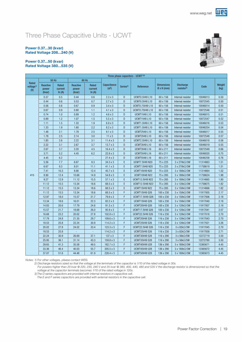
Power Factor Correction 19
Three Phase Capacitive Units - UCWT
Three phase capacitors - UCWT1)2)
Ratedvoltage1)
(V)
50 Hz 60 Hz
Capacitance (uF)
Series3) ReferenceDimensions Ø x H (mm)
Discharge resistor2) Code
Weight (kg)
Reactive power (kvar)
Rated current In (A)
Reactive power (kvar)
Rated current In (A)
415
0.37 0.5 0.44 0.6 2.3 x 3 D UCWT0.5V49 L10 60 x 156 Internal resistor 10046013 0.50
0.44 0.6 0.53 0.7 2.7 x 3 D UCWT0.5V48 L10 60 x 156 Internal resistor 10072545 0.50
0.56 0.8 0.67 0.9 3.4 x 3 D UCWT0.75V49 L10 60 x 156 Internal resistor 10046014 0.50
0.67 0.9 0.80 1.1 4.1 x 3 D UCWT0.75V48 L10 60 x 156 Internal resistor 10072546 0.51
0.74 1.0 0.89 1.2 4.6 x 3 D UCWT1V49 L10 60 x 156 Internal resistor 10046015 0.51
0.89 1.2 1.07 1.5 5.5 x 3 D UCWT1V48 L10 60 x 156 Internal resistor 10072547 0.52
1.11 1.5 1.33 1.9 6.9 x 3 D UCWT1.5V49 L10 60 x 156 Internal resistor 10046016 0.53
1.33 1.9 1.60 2.2 8.2 x 3 D UCWT1.5V48 L10 60 x 156 Internal resistor 10046254 0.54
1.48 2.1 1.78 2.5 9.1 x 3 D UCWT2V49 L10 60 x 156 Internal resistor 10046017 0.55
1.78 2.5 2.14 3.0 11 x 3 D UCWT2V48 L10 60 x 156 Internal resistor 10072548 0.57
1.85 2.6 2.22 3.1 11.4 x 3 D UCWT2.5V49 L10 60 x 156 Internal resistor 10046018 0.56
2.22 3.1 2.67 3.7 13.7 x 3 D UCWT3V49 L10 60 x 156 Internal resistor 10046019 0.55
2.67 3.7 3.20 4.5 16.4 x 3 D UCWT3V48 L16 60 x 211 Internal resistor 10072549 0.66
3.71 5.2 4.45 6.2 22.8 x 3 D UCWT5V49 L16 60 x 211 Internal resistor 10046020 0.75
4.45 6.2 - - 27.4 x 3 D UCWT5V48 L16 60 x 211 Internal resistor 10046258 0.76
5.56 7.7 6.67 9.3 34.3 x 3 E UCWT7.5V49 N20 75 x 225 3 x 270kΩ/3W 11314663 1.51
6.67 9.3 8.01 11.1 41.1 x 3 E UCWT7.5V48 N20 75 x 225 3 x 270kΩ/3W 11758619 1.51
7.41 10.3 8.90 12.4 45.7 x 3 E UCWT10V49 N20 75 x 225 3 x 180kΩ/3W 11314664 1.52
8.90 12.4 10.68 14.9 54.8 x 3 E UCWT10V48 N22 75 x 285 3 x 180kΩ/3W 11758624 1.98
9.27 12.9 11.12 15.5 57.1 x 3 E UCWT12.5V49 N22 75 x 285 3 x 180kΩ/3W 11314665 1.80
11.12 15.5 13.34 18.6 68.5 x 3 E UCWT12.5V48 N22 75 x 285 3 x 120kΩ/3W 11758675 1.82
11.12 15.5 13.34 18.6 68.5 x 3 E UCWT15V49 N22 75 x 285 3 x 150kΩ/3W 11314666 1.82
11.12 15.5 13.34 18.6 68.5 x 3 F UCWT15V49 Q26 100 x 230 3 x 150kΩ/3W 11917005 2.17
12.97 18.0 15.57 21.7 79.9 x 3 F UCWT17.5V49 Q26 100 x 230 3 x 150kΩ/3W 11917006 2.18
13.34 18.6 16.01 22.3 82.2 x 3 F UCWT15V48 Q26 100 x 230 3 x 150kΩ/3W 11917040 2.18
14.83 20.6 17.79 24.8 91.3 x 3 F UCWT20V49 Q26 100 x 230 3 x 120kΩ/3W 11917007 2.18
15.57 21.7 18.68 26.0 95.9 x 3 F UCWT17.5V48 Q26 100 x 230 3 x 120kΩ/3W 11917041 2.07
16.68 23.2 20.02 27.8 102.8 x 3 F UCWT22.5V49 S26 116 x 230 3 x 120kΩ/3W 11917018 2.70
17.79 24.8 21.35 29.7 109.6 x 3 F UCWT20V48 S26 116 x 230 3 x 120kΩ/3W 11917043 2.70
18.53 25.8 22.24 30.9 114.2 x 3 F UCWT25V49 S26 116 x 230 3 x 120kΩ/3W 11917021 3.26
20.02 27.8 24.02 33.4 123.3 x 3 F UCWT22.5V48 S26 116 x 230 3 x 82kΩ/3W 11917045 2.70
18.53 25.8 - - 114.2 x 3 F UCWT25V48 S26 116 x 230 3 x 82kΩ/3W 11917058 2.71
22.24 30.9 26.69 37.1 137 x 3 F UCWT30V49 S28 116 x 290 3 x 56kΩ/5W 12272719 3.50
25.95 36.1 31.14 43.3 159.8 x 3 F UCWT35V49 S28 116 x 290 3 x 56kΩ/5W 12272780 3.50
29.65 41.3 35.58 49.5 182.7 x 3 F UCWT40V49 U28 136 x 290 3 x 180kΩ/3W 13365671 4.45
33.36 46.4 40.03 55.7 205.5 x 3 F UCWT45V49 U28 136 x 290 3 x 180kΩ/3W 13365672 4.45
37.07 51.6 44.48 61.9 228.4 x 3 F UCWT50V49 U28 136 x 290 3 x 180kΩ/3W 13365673 4.45
Power 0.37...30 (kvar)Rated Voltage 208...240 (V)
Power 0.37...50 (kvar)Rated Voltage 380...535 (V)
Notes: 1) For other voltages, please contact WEG. 2) Discharge resistors sized so that the voltage at the terminals of the capacitor is 1/10 of the rated voltage in 30s.
For powers higher than 20 kvar @ 220, 230, 240 V and 35 kvar @ 380, 400, 440, 480 and 535 V the discharge resistor is dimensioned so that the voltage at the capacitor terminals becomes 1/10 of the rated voltage in 120s.
3) The D series capacitors are provided with internal resistors in capacitive cell. The E and F series capacitors are provided with external resistors in the capacitive cell.

www.weg.net
Power Factor Correction 20
Three Phase Capacitive Units - UCWT
Three phase capacitors - UCWT1)2)
Ratedvoltage1)
(V)
50 Hz 60 Hz
Capacitance (uF)
Series3) ReferenceDimensions Ø x H (mm)
Discharge resistor2) Code
Weight (kg)
Reactive power (kvar)
Rated current In (A)
Reactive power (kvar)
Rated current In (A)
440
0.42 0.5 0.50 0.7 2.3 x 3 D UCWT0.5V49 L10 60 x 156 Internal resistor 10046013 0.50
0.50 0.7 0.60 0.8 2.7 x 3 D UCWT0.5V48 L10 60 x 156 Internal resistor 10072545 0.50
0.63 0.8 0.75 1.0 3.4 x 3 D UCWT0.75V49 L10 60 x 156 Internal resistor 10046014 0.50
0.75 1.0 0.90 1.2 4.1 x 3 D UCWT0.75V48 L10 60 x 156 Internal resistor 10072546 0.51
0.83 1.1 1.00 1.3 4.6 x 3 D UCWT1V49 L10 60 x 156 Internal resistor 10046015 0.51
1.00 1.3 1.20 1.6 5.5 x 3 D UCWT1V48 L10 60 x 156 Internal resistor 10072547 0.52
1.25 1.6 1.50 2.0 6.9 x 3 D UCWT1.5V49 L10 60 x 156 Internal resistor 10046016 0.53
1.50 2.0 1.80 2.4 8.2 x 3 D UCWT1.5V48 L10 60 x 156 Internal resistor 10046254 0.54
1.67 2.2 2.00 2.6 9.1 x 3 D UCWT2V49 L10 60 x 156 Internal resistor 10046017 0.55
2.00 2.6 2.40 3.1 11 x 3 D UCWT2V48 L10 60 x 156 Internal resistor 10072548 0.57
2.08 2.7 2.50 3.3 11.4 x 3 D UCWT2.5V49 L10 60 x 156 Internal resistor 10046018 0.56
2.50 3.3 3.00 3.9 13.7 x 3 D UCWT3V49 L10 60 x 156 Internal resistor 10046019 0.55
3.00 3.9 3.60 4.7 16.4 x 3 D UCWT3V48 L16 60 x 211 Internal resistor 10072549 0.66
4.17 5.5 5.00 6.6 22.8 x 3 D UCWT5V49 L16 60 x 211 Internal resistor 10046020 0.75
5.00 6.6 - - 27.4 x 3 D UCWT5V48 L16 60 x 211 Internal resistor 10046258 0.76
6.25 8.2 7.50 9.8 34.3 x 3 E UCWT7.5V49 N20 75 x 225 3 x 270kΩ/3W 11314663 1.51
7.50 9.8 9.00 11.8 41.1 x 3 E UCWT7.5V48 N20 75 x 225 3 x 270kΩ/3W 11758619 1.51
8.33 10.9 10.00 13.1 45.7 x 3 E UCWT10V49 N20 75 x 225 3 x 180kΩ/3W 11314664 1.52
10.00 13.1 12.00 15.7 54.8 x 3 E UCWT10V48 N22 75 x 285 3 x 180kΩ/3W 11758624 1.98
10.42 13.7 12.50 16.4 57.1 x 3 E UCWT12.5V49 N22 75 x 285 3 x 180kΩ/3W 11314665 1.80
12.50 16.4 15.00 19.7 68.5 x 3 E UCWT12.5V48 N22 75 x 285 3 x 120kΩ/3W 11758675 1.82
12.50 16.4 15.00 19.7 68.5 x 3 E UCWT15V49 N22 75 x 285 3 x 150kΩ/3W 11314666 1.82
12.50 16.4 15.00 19.7 68.5 x 3 F UCWT15V49 Q26 100 x 230 3 x 150kΩ/3W 11917005 2.17
14.58 19.1 17.50 23.0 79.9 x 3 F UCWT17.5V49 Q26 100 x 230 3 x 150kΩ/3W 11917006 2.18
15.00 19.7 18.00 23.6 82.2 x 3 F UCWT15V48 Q26 100 x 230 3 x 150kΩ/3W 11917040 2.18
16.67 21.9 20.00 26.2 91.3 x 3 F UCWT20V49 Q26 100 x 230 3 x 120kΩ/3W 11917007 2.18
17.50 23.0 - - 95.9 x 3 F UCWT17.5V48 Q26 100 x 230 3 x 120kΩ/3W 11917041 2.07
18.75 24.6 22.50 29.5 102.8 x 3 F UCWT22.5V49 S26 116 x 230 3 x 120kΩ/3W 11917018 2.70
20.00 26.2 24.00 31.5 109.6 x 3 F UCWT20V48 S26 116 x 230 3 x 120kΩ/3W 11917043 2.70
20.83 27.3 25.00 32.8 114.2 x 3 F UCWT25V49 S26 116 x 230 3 x 120kΩ/3W 11917021 3.26
22.50 29.5 - - 123.3 x 3 F UCWT22.5V48 S26 116 x 230 3 x 82kΩ/3W 11917045 2.70
25.00 32.8 - - 137 x 3 F UCWT25V48 S26 116 x 230 3 x 82kΩ/3W 11917058 2.71
25.00 32.8 30.00 39.4 137 x 3 F UCWT30V49 S28 116 x 290 3 x 56kΩ/5W 12272719 3.50
29.17 38.3 35.00 45.9 159.8 x 3 F UCWT35V49 S28 116 x 290 3 x 56kΩ/5W 12272780 3.50
33.33 43.7 40.00 52.5 182.7 x 3 F UCWT40V49 U28 136 x 290 3 x 180kΩ/3W 13365671 4.45
37.50 49.2 45.00 59.0 205.5 x 3 F UCWT45V49 U28 136 x 290 3 x 180kΩ/3W 13365672 4.45
41.67 54.7 50.00 65.6 228.4 x 3 F UCWT50V49 U28 136 x 290 3 x 180kΩ/3W 13365673 4.45
Power 0.37...30 (kvar)Rated Voltage 208...240 (V)
Power 0.37...50 (kvar)Rated Voltage 380...535 (V)
Notes: 1) For other voltages, please contact WEG. 2) Discharge resistors sized so that the voltage at the terminals of the capacitor is 1/10 of the rated voltage in 30s.
For powers higher than 20 kvar @ 220, 230, 240 V and 35 kvar @ 380, 400, 440, 480 and 535 V the discharge resistor is dimensioned so that the voltage at the capacitor terminals becomes 1/10 of the rated voltage in 120s.
3) The D series capacitors are provided with internal resistors in capacitive cell. The E and F series capacitors are provided with external resistors in the capacitive cell.

www.weg.net
Power Factor Correction 21
Three Phase Capacitive Units - UCWT
Three phase capacitors - UCWT1)2)
Ratedvoltage1)
(V)
50 Hz 60 Hz
Capacitance (uF)
Series3) ReferenceDimensions Ø x H (mm)
Discharge resistor2) Code
Weight (kg)
Reactive power (kvar)
Rated current In (A)
Reactive power (kvar)
Rated current In (A)
480
0.42 0.5 0.50 0.6 1.9 x 3 D UCWT0.5V53 L10 60 x 156 Internal resistor 10045990 0.49
0.50 0.6 0.60 0.7 2.3 x 3 D UCWT0.5V52 L10 60 x 156 Internal resistor 10046259 0.50
0.63 0.8 0.75 0.9 2.9 x 3 D UCWT0.75V53 L10 60 x 156 Internal resistor 10045991 0.51
0.75 0.9 0.90 1.1 3.5 x 3 D UCWT0.75V52 L10 60 x 156 Internal resistor 10072550 0.51
0.83 1.0 1.00 1.2 3.8 x 3 D UCWT1V53 L10 60 x 156 Internal resistor 10045992 0.50
1.00 1.2 1.20 1.4 4.6 x 3 D UCWT1V52 L10 60 x 156 Internal resistor 10072551 0.51
1.25 1.5 1.50 1.8 5.8 x 3 D UCWT1.5V53 L10 60 x 156 Internal resistor 10045993 0.52
1.50 1.8 1.80 2.2 6.9 x 3 D UCWT1.5V52 L10 60 x 156 Internal resistor 10072552 0.54
1.67 2.0 2.00 2.4 7.7 x 3 D UCWT2V53 L10 60 x 156 Internal resistor 10045994 0.53
2.00 2.4 2.40 2.9 9.2 x 3 D UCWT2V52 L10 60 x 156 Internal resistor 10072553 0.54
2.08 2.5 2.50 3.0 9.6 x 3 D UCWT2.5V53 L10 60 x 156 Internal resistor 10045995 0.56
2.50 3.0 3.00 3.6 11.5 x 3 D UCWT2.5V52 L10 60 x 156 Internal resistor 10072554 0.58
3.00 3.6 3.60 4.3 13.8 x 3 D UCWT3V52 L10 60 x 156 Internal resistor 10072555 0.55
4.17 5.0 5.00 6.0 19.2 x 3 D UCWT5V53 L16 60 x 211 Internal resistor 10045997 0.73
5.00 6.0 - - 23 x 3 D UCWT5V52 L16 60 x 211 Internal resistor 10072556 0.78
6.25 7.5 7.50 9.0 28.8 x 3 E UCWT7.5V53 N20 75 x 225 3 x 390kΩ/3W 11314667 1.50
7.50 9.0 9.00 10.8 34.5 x 3 E UCWT7.5V52 N20 75 x 225 3 x 270kΩ/3W 11758740 1.50
8.33 10.0 10.00 12.0 38.4 x 3 E UCWT10V53 N20 75 x 225 3 x 270kΩ/3W 11314728 1.53
10.00 12.0 12.00 14.4 46.1 x 3 E UCWT10V52 N22 75 x 285 3 x 180kΩ/3W 11758742 1.97
10.42 12.5 12.50 15.0 48 x 3 E UCWT12.5V53 N22 75 x 285 3 x 180kΩ/3W 11314729 1.79
12.50 15.0 15.00 18.0 57.6 x 3 E UCWT12.5V52 N22 75 x 285 3 x 180kΩ/3W 11758746 2.17
12.50 15.0 15.00 18.0 57.6 x 3 E UCWT15V53 N22 75 x 285 3 x 180kΩ/3W 11314730 1.81
12.50 15.0 15.00 18.0 57.6 x 3 F UCWT15V53 Q26 100 x 230 3 x 180kΩ/3W 11917060 2.17
14.58 17.5 17.50 21.0 67.2 x 3 F UCWT17.5V53 Q26 100 x 230 3 x 180kΩ/3W 11917063 2.18
15.00 18.0 18.00 21.7 69.1 x 3 F UCWT15V52 Q26 100 x 230 3 x 180kΩ/3W 11917094 2.17
16.67 20.0 20.00 24.1 76.8 x 3 F UCWT20V53 Q26 100 x 230 3 x 150kΩ/3W 11917064 2.18
17.50 21.0 - - 80.6 x 3 F UCWT17.5V52 Q26 100 x 230 3 x 150kΩ/3W 11917095 2.32
18.75 22.6 22.50 27.1 86.3 x 3 F UCWT22.5V53 S26 116 x 230 3 x 120kΩ/3W 11917065 2.69
20.00 24.1 24.00 28.9 92.1 x 3 F UCWT20V52 S26 116 x 230 3 x 120kΩ/3W 11917097 2.69
20.83 25.1 25.00 30.1 95.9 x 3 F UCWT25V53 S26 116 x 230 3 x 120kΩ/3W 11917066 2.99
22.50 27.1 - - 103.6 x 3 F UCWT22.5V52 S26 116 x 230 3 x 120kΩ/3W 11917128 2.71
25.00 30.1 - - 115.1 x 3 F UCWT25V52 S26 116 x 230 3 x 120kΩ/3W 11917129 2.71
25.00 30.1 30.00 36.1 115.1 x 3 F UCWT30V53 S28 116 x 290 3 x 82kΩ/5W 12272781 3.50
29.17 35.1 35.00 42.1 134.3 x 3 F UCWT35V53 S28 116 x 290 3 x 82kΩ/5W 12272784 3.50
33.33 40.1 40.00 48.1 153.5 x 3 F UCWT40V53 U28 136 x 290 3 x 270kΩ/3W 13365674 4.45
37.50 45.1 45.00 54.1 172.7 x 3 F UCWT45V53 U28 136 x 290 3 x 180kΩ/3W 13365675 4.45
41.67 50.1 50.00 60.1 191.9 x 3 F UCWT50V53 U28 136 x 290 3 x 180kΩ/3W 13365677 4.45
Power 0.37...30 (kvar)Rated Voltage 208...240 (V)
Power 0.37...50 (kvar)Rated Voltage 380...535 (V)
Notes: 1) For other voltages, please contact WEG. 2) Discharge resistors sized so that the voltage at the terminals of the capacitor is 1/10 of the rated voltage in 30s.
For powers higher than 20 kvar @ 220, 230, 240 V and 35 kvar @ 380, 400, 440, 480 and 535 V the discharge resistor is dimensioned so that the voltage at the capacitor terminals becomes 1/10 of the rated voltage in 120s.
3) The D series capacitors are provided with internal resistors in capacitive cell. The E and F series capacitors are provided with external resistors in the capacitive cell.

www.weg.net
Power Factor Correction 22
Three Phase Capacitive Units - UCWT
Power 0.37...20 (kvar)Rated Voltage 208...240 (V)
Power 0.37...35 (kvar)Rated Voltage 380...535 (V)
Three phase capacitors - UCWT1)2)
Ratedvoltage1)
(V)
50 Hz 60 Hz
Capacitance (uF)
Series3) ReferenceDimensions Ø x H (mm)
Discharge resistor2) Code
Weight (kg)
Reactive power (kvar)
Rated current In (A)
Reactive power (kvar)
Rated current In (A)
525
5.00 5.5 - - 19.2 x 3 D UCWT5VD2 L16 60 x 211 Internal resistor 12634786 0.83
10.00 11.0 12.00 13.2 38.5 x 3 F UCWT10VD2 Q26 100 x 230 3 x 180kΩ/3W 12634787 2.57
15.00 16.5 18.00 19.8 57.7 x 3 F UCWT15VD2 Q26 100 x 230 3 x 180kΩ/3W 12634848 2.61
20.00 22.0 - - 77 x 3 F UCWT20VD2 S26 116 x 230 3 x 150kΩ/3W 12634849 3.34
25.00 27.5 30.00 33.0 96.2 x 3 F UCWT25VD2 S28 116 x 290 3 x 82kΩ/3W 12634850 3.67
30.00 33.0 - - 115.5 x 3 F UCWT30VD2 S28 116 x 290 3 x 82kΩ/3W 12634851 3.55
40.00 44.0 48.00 52.8 154 x 3 F UCWT40VD2 U28 136 x 290 3 x 270kΩ/3W 13365679 4.45
535
0.42 0.4 0.50 0.5 1.5 x 3 D UCWT0.5V57 L10 60 x 156 Internal resistor 10743966 0.38
0.63 0.7 0.75 0.8 2.3 x 3 D UCWT0.75V57 L10 60 x 156 Internal resistor 10744000 0.40
0.83 0.9 1.00 1.1 3.1 x 3 D UCWT1V57 L10 60 x 156 Internal resistor 10744001 0.42
1.25 1.3 1.50 1.6 4.6 x 3 D UCWT1.5V57 L10 60 x 156 Internal resistor 10744036 0.46
1.67 1.8 2.00 2.2 6.2 x 3 D UCWT2V57 L10 60 x 156 Internal resistor 10748191 0.48
2.08 2.2 2.50 2.7 7.7 x 3 D UCWT2.5V57 L10 60 x 156 Internal resistor 10748192 0.53
2.50 2.7 3.00 3.2 9.3 x 3 D UCWT3V57 L10 60 x 156 Internal resistor 10748195 0.67
4.17 4.5 5.00 5.4 15.4 x 3 D UCWT5V57 L16 60 x 211 Internal resistor 10648884 0.75
6.25 6.7 7.50 8.1 23.2 x 3 E UCWT7.5V57 N20 75 x 225 3 x 390kΩ/3W 11314731 1.50
8.33 9.0 10.00 10.8 30.9 x 3 E UCWT10V57 N20 75 x 225 3 x 270kΩ/3W 11314732 1.53
10.42 11.2 12.50 13.5 38.6 x 3 E UCWT12.5V57 N22 75 x 285 3 x 270kΩ/3W 11314733 1.79
12.50 13.5 15.00 16.2 46.3 x 3 E UCWT15V57 N22 75 x 285 3 x 270kΩ/3W 11314734 1.79
12.50 13.5 15.00 16.2 46.3 x 3 F UCWT15V57 Q26 100 x 230 3 x 180kΩ/3W 11917359 2.17
14.58 15.7 17.50 18.9 54.1 x 3 F UCWT17.5V57 Q26 100 x 230 3 x 180kΩ/3W 11917361 2.18
16.67 18.0 20.00 21.6 61.8 x 3 F UCWT20V57 Q26 100 x 230 3 x 180kΩ/3W 11917362 2.18
18.75 20.2 22.50 24.3 69.5 x 3 F UCWT22.5V57 S26 116 x 230 3 x 150kΩ/3W 11917364 2.69
20.83 22.5 25.00 27.0 77.2 x 3 F UCWT25V57 S26 116 x 230 3 x 150kΩ/3W 11917366 2.70
25.00 27.0 30.00 32.4 92.7 x 3 F UCWT30V57 S28 116 x 290 3 x 82kΩ/5W 12273233 3.50
29.17 31.5 35.00 37.8 108.1 x 3 F UCWT35V57 S28 116 x 290 3 x 82kΩ/5W 12273234 3.50
33.33 36.0 40.00 43.2 123.6 x 3 F UCWT40V57 U28 136 x 290 3 x 270kΩ/3W 13365680 4.45
37.50 40.5 45.00 48.6 139 x 3 F UCWT45V57 U28 136 x 290 3 x 270kΩ/3W 13365682 4.45
41.67 45.0 50.00 54.0 154.5 x 3 F UCWT50V57 U28 136 x 290 3 x 270kΩ/3W 13365683 4.45
Notes: 1) For other voltages, please contact WEG. 2) Discharge resistors sized so that the voltage at the terminals of the capacitor is 1/10 of the rated voltage in 30s.
For powers higher than 20 kvar @ 220, 230, 240 V and 35 kvar @ 380, 400, 440, 480 and 535 V the discharge resistor is dimensioned so that the voltage at the capacitor terminals becomes 1/10 of the rated voltage in 120s.
3) The D series capacitors are provided with internal resistors in capacitive cell. The E and F series capacitors are provided with external resistors in the capacitive cell.

www.weg.net
Power Factor Correction 23
Capacitive Units - Technical Data
Notes: 1) Maximum altitude: 2,000 m. For application in higher altitudes, please contact WEG.
2) IRAM Certification available for capacitors of the following voltage / frequency: 230 V / 50 Hz, 400 V / 50 Hz, 440 V / 50 Hz e 480 V / 50 Hz. 3) in progress to capacitors 136 x 290 mm. Capacitors in 535 V without IRAM certification.
4) in progress to capacitors 116 x 290 mm and 136 x 290 mm.
Notes: 1) For terminal type Positive Lock. 2) Valid for capacitors 116 x 290 mm and 136 x 290 mm.
R
US
Technical characteristics A series B series C series D series E series F series
Phases Single phase Three-phasePower 0.62...0.83 (kvar) 0.62...6.67 (kvar) 3.72...10 (kvar) 0.37...5 (kvar) 3.72...15 (kvar) 7.45...50 (kvar)Rated voltage 380...535 (V) 208...535 (V)Rated frequency 50 or 60 (Hz)Capacitance tolerance ±5 (%)Useful life 100,000 (h)
Temperature class
-25/D Minimum temperature: -25 ºC
Max temperature: D Max. temp.= 55 ºC
Avg. max. temp. in 24h = 45 ºC Avg. max. temp. in 1 year = 35 ºC
SafetySelf-healing polypropylene film Disconnection for overpressure
Max. short circuit capacity 10 (kA)Protection degree IP00 IP00 IP20 IP50 IP20Max. altitude1) 2,000 (m)Discharge resistance Fast-on terminal Inside the product Fast-on terminalDischarge resistor Not included IncludedCapacitor fixing M8 bolt M12 boltMax. torque for capacitor 12 (N.m) 14 (N.m)Impregnation Polyurethane resin
Max. voltage1.1 x Vn 8h
Duration for each 24h - not continuous (system fluctuation)Max. dV/dt ≤30 (V/µm)Max. current 1.3 x In (short periods of time)Max. inrush current ≤100 x InVoltage test between terminals 2.15 x Vn @ 2sVoltage test between terminals and enclosure 3.6 kV @ 2s 3.6 kV @ 2s
Reference standards IEC 60831-1/2 UL 810
Certifications2)R
US
2)R
US
R
US
2)R
US
R
US
R
US
3) 4)
Connection type
Terminal type
Type clamping screw
UCW Series A
UCW Series B
UCW Series C
UCWT Series D
UCWT Series E
UCWT Series F
Cross-section (mm2)
1)
- 0.5...6.0 - - - - -
M3x2,4 Slot/Philips
- 0.5 ... 6.0 - 0.5 ... 6.0 - -M3x2,4
Slot/Philips
M4x16,5 Slot/Philips
- - 1.5 ... 10.0 - 0.5 ... 6.0 1.5 ... 10.0
2)
M8 hexagon socket
- - - - - 10.0 ... 35.0
Torque (Nm)
- 0.8 ... 1.5 1.5 ... 2.5 0.8 ... 1.5 1.5 ... 2.51.5 ... 2.5 4.0 ... 6.02)N.m
Cross-Section and Tightening Torque

www.weg.net
Power Factor Correction 24
Notes: 1) For other voltages, please contact WEG. 2) Three phase capacitive modules are provided with discharge resistors.
Three Phase Capacitive Module - MCW
Power 1.86...10 (kvar) Rated Voltage 208...240 (V)
Power 1.85...15 (kvar)Rated Voltage 380...535 (V)
Three phase capacitive module - MCW1)2)
Rated voltage (V)
50 Hz 60 Hz
Reference
Composition quant. x
UCW / MCW (D connection)
Dimensions (L x W x H) (mm)
CodeWeight
(kg)Reactive power (kvar)
Rated current In (A)
Reactive power (kvar)
Rated current In (A)
208
1.86 5.2 2.23 6.2 MCW2.5V25 3xUCW0.83V25 L6 219 x 78 x 257 10045851 3.013.72 10.3 4.47 12.4 MCW5V25 3xUCW1.67V25 L6 219 x 78 x 257 10045799 3.045.59 15.5 6.70 18.6 MCW7.5V25 3xUCW2.5V25 L10 219 x 78 x 257 10186130 3.627.45 20.7 8.94 24.8 MCW10V25 3xUCW3.33V25 L10 219 x 78 x 257 10046861 3.65
220
2.08 5.5 2.50 6.6 MCW2.5V25 3xUCW0.83V25 L6 219 x 78 x 257 10045851 3.014.17 10.9 5.00 13.1 MCW5V25 3xUCW1.67V25 L6 219 x 78 x 257 10045799 3.046.25 16.4 7.50 19.7 MCW7.5V25 3xUCW2.5V25 L10 219 x 78 x 257 10186130 3.628.33 21.9 10.00 26.2 MCW10V25 3xUCW3.33V25 L10 219 x 78 x 257 10046861 3.65
230
2.50 6.3 3.00 7.5 MCW2.5V34 3xUCW0.83V34 L6 219 x 78 x 257 10072478 2.955.00 12.6 6.00 15.1 MCW5V34 3xUCW1.67V34 L6 219 x 78 x 257 10211646 3.437.50 18.8 9.00 22.6 MCW7.5V34 3xUCW2.5V34 L10 219 x 78 x 257 10211647 3.6210.00 25.1 12.00 30.1 MCW10V34 3xUCW3.33V34 L10 219 x 78 x 257 11559337 3.62
240
2.08 5.0 2.50 6.0 MCW2.5V29 3xUCW0.83V29 L4 219 x 78 x 257 10072559 3.044.17 10.0 5.00 12.0 MCW5V29 3xUCW1.67V29 L6 219 x 78 x 257 10045989 3.016.25 15.0 7.50 18.0 MCW7.5V29 3xUCW2.5V29 L10 219 x 78 x 257 10072302 3.478.33 20.0 10.00 24.1 MCW10V29 3xUCW3.3V29 L10 219 x 78 x 257 11214119 3.66
380
2.08 3.2 2.50 3.8 MCW2.5V40 3xUCW0.83V40 L4 219 x 78 x 257 10452269 2.294.17 6.3 5.00 7.6 MCW5V40 3xUCW1.67V40 L4 219 x 78 x 257 10186090 2.326.25 9.5 7.50 11.4 MCW7.5V40 3xUCW2.5V40 L6 219 x 78 x 257 10186099 3.088.33 12.7 10.00 15.2 MCW10V40 3xUCW3.33V40 L8 219 x 78 x 257 10186092 3.6612.50 19.0 15.00 22.8 MCW15V40 3xUCW5V40 L10 219 x 78 x 257 10186131 3.67
400
2.50 3.6 3.00 4.3 MCW2.5V44 3xUCW0.83V44 L4 219 x 78 x 257 10072333 2.475.00 7.2 6.00 8.7 MCW5V44 3xUCW1.67V44 L4 219 x 78 x 257 10072334 2.377.50 10.8 9.00 13.0 MCW7.5V44 3xUCW2.5V44 L6 219 x 78 x 257 10186140 3.0310.00 14.4 12.00 17.3 MCW10V44 3xUCW3.33V44 L8 219 x 78 x 257 10046040 3.5315.00 21.7 18.00 45.2 MCW15V44 3xUCW5V44 L10 219 x 78 x 257 10046041 3.63
415
1.85 2.6 2.22 3.1 MCW2.5V49 3xUCW0.83V49 L4 219 x 78 x 257 10045854 2.352.22 3.1 2.67 3.7 MCW2.5V48 3xUCW0.83V48 L4 219 x 78 x 257 10072479 2.403.71 5.2 4.45 6.2 MCW5V49 3xUCW1.67V49 L4 219 x 78 x 257 10186091 2.354.45 6.2 5.34 7.4 MCW5V48 3xUCW1.67V48 L4 219 x 78 x 257 10072480 2.375.56 7.7 6.67 9.3 MCW7.5V49 3xUCW2.5V49 L6 219 x 78 x 257 10045855 3.086.67 9.3 8.01 11.1 MCW7.5V48 3xUCW2.5V48 L6 219 x 78 x 257 10072481 3.037.41 10.3 8.90 12.4 MCW10V49 3xUCW3.33V49 L8 219 x 78 x 257 10186093 3.568.90 12.4 10.68 14.9 MCW10V48 3xUCW3.33V48 L8 219 x 78 x 257 10072482 3.5311.12 15.5 13.34 18.6 MCW15V49 3xUCW5V49 L10 219 x 78 x 257 10045983 3.7613.34 18.6 16.01 40.2 MCW15V48 3xUCW5V48 L10 219 x 78 x 257 11608707 3.70
440
2.08 2.7 2.50 3.3 MCW2.5V49 3xUCW0.83V49 L4 219 x 78 x 257 10045854 2.352.50 3.3 3.00 3.9 MCW2.5V48 3xUCW0.83V48 L4 219 x 78 x 257 10072479 2.404.17 5.5 5.00 6.6 MCW5V49 3xUCW1.67V49 L4 219 x 78 x 257 10186091 2.355.00 6.6 6.00 7.9 MCW5V48 3xUCW1.67V48 L4 219 x 78 x 257 10072480 2.376.25 8.2 7.50 9.8 MCW7.5V49 3xUCW2.5V49 L6 219 x 78 x 257 10045855 3.087.50 9.8 9.00 11.8 MCW7.5V48 3xUCW2.5V48 L6 219 x 78 x 257 10072481 3.038.33 10.9 10.00 13.1 MCW10V49 3xUCW3.33V49 L8 219 x 78 x 257 10186093 3.5610.00 13.1 12.00 15.7 MCW10V48 3xUCW3.33V48 L8 219 x 78 x 257 10072482 3.5312.50 16.4 15.00 19.7 MCW15V49 3xUCW5V49 L10 219 x 78 x 257 10045983 3.7615.00 19.7 18.00 45.2 MCW15V48 3xUCW5V48 L10 219 x 78 x 257 11608707 3.70
480
2.08 2.5 2.50 3.0 MCW2.5V53 3xUCW0.83V53 L6 219 x 78 x 257 10045856 2.922.50 3.0 3.00 3.6 MCW2.5V52 3xUCW0.83V52 L6 219 x 78 x 257 10072484 2.994.17 5.0 5.00 6.0 MCW5V53 3xUCW1.67V53 L6 219 x 78 x 257 10045857 2.945.00 6.0 6.00 7.2 MCW5V52 3xUCW1.67V52 L6 219 x 78 x 257 10072485 2.996.25 7.5 7.50 9.0 MCW7.5V53 3xUCW2.5V53 L6 219 x 78 x 257 10186100 2.977.50 9.0 9.00 10.8 MCW7.5V52 3xUCW2.5V52 L6 219 x 78 x 257 10072486 3.008.33 10.0 10.00 12.0 MCW10V53 3xUCW3.33V53 L8 219 x 78 x 257 10186101 3.4610.00 12.0 12.00 14.4 MCW10V52 3xUCW3.33V52 L8 219 x 78 x 257 10072487 3.4212.50 15.0 15.00 18.0 MCW15V53 3xUCW5V53 L10 219 x 78 x 257 10045984 3.6615.00 18.0 18.00 45.2 MCW15V52 3xUCW5V52 L10 219 x 78 x 257 10072488 3.73
535
2.08 2.2 2.50 2.7 MCW2.5V57 3xUCW0.83V57 L6 219 x 78 x 257 10073617 2.874.17 4.5 5.00 5.4 MCW5V57 3xUCW1.67V57 L6 219 x 78 x 257 10046601 2.886.25 6.7 7.50 8.1 MCW7.5V57 3xUCW2.5V57 L6 219 x 78 x 257 10046602 2.978.33 9.0 10.00 10.8 MCW10V57 3xUCW3.33V57 L6 219 x 78 x 257 10046603 3.0112.50 13.5 15.00 16.2 MCW15V57 3xUCW5V57 L10 219 x 78 x 257 10046604 3.63

www.weg.net
Power Factor Correction 25
Note: 1) Maximum altitude: 2,000 m. For application in higher altitudes, please contact WEG.
Capacitive Module - Technical Data
Technical characteristics MCW
Phases Three-phase
Power1.86...10 (kvar) for 208...240 (V) 1.85...15 (kvar) for 380...535 (V)
Rated voltage 208...535 (V)
Rated frequency 50 or 60 (Hz)
Capacitance tolerance ±5 (%)
Useful life 100,000 (h)
Temperature class
-25/D Minimum temperature: -25 ºC
Max temperature: D Max. temp.= 55 ºC
Avg. max. temp. in 24h = 45 ºC Avg. max. temp. in 1 year = 35 ºC
SafetySelf-healing polypropylene film Disconnection for overpressure
Max. short circuit capacity 10 (kA)
Protection degree IP40
Max. altitude 1) 2,000 (m)
Discharge resistor Included
Impregnation Polyurethane resin
Max. voltage1.1 x Vn
8h duration for each 24h - not continuous (system fluctuation)
Max. dV/dt ≤30 (V/µm)
Max. current 1.3 x In (short periods of time)
Max. in-rush current ≤100 x In
Voltage test between terminals 2.15 x Vn @ 2s
Voltage test between terminals and enclosure 3 kV @ 2s
Reference standards IEC 60831-1/2 UL 810
CertificationsR
US
Cross-Section and Tightening Torque
Connection type Terminal type Type clamping screw MCW
Section (mm²) Eyelet M8 1.5...35.0
Torque(Nm) Nm 8.0...10.0
www.weg.net
Power Factor Correction 26
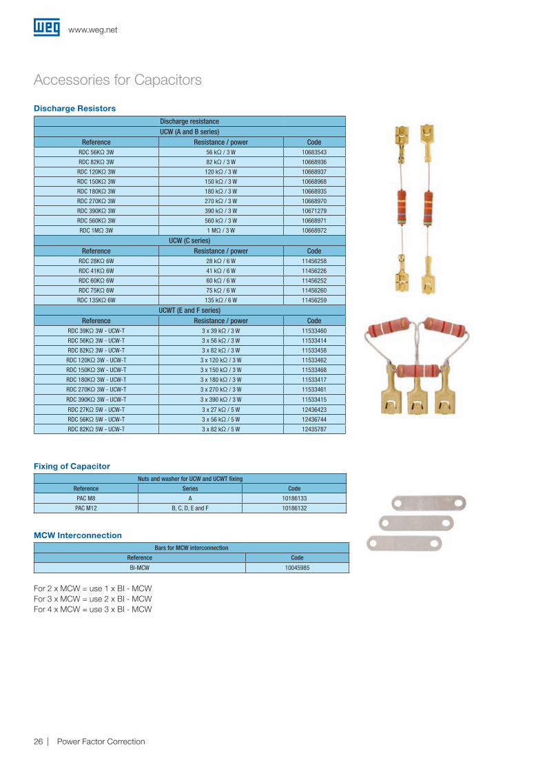
Accessories for Capacitors
For 2 x MCW = use 1 x BI - MCWFor 3 x MCW = use 2 x BI - MCWFor 4 x MCW = use 3 x BI - MCW
Discharge Resistors
Discharge resistanceUCW (A and B series)
Reference Resistance / power CodeRDC 56KΩ 3W 56 kΩ / 3 W 10683543
RDC 82KΩ 3W 82 kΩ / 3 W 10668936
RDC 120KΩ 3W 120 kΩ / 3 W 10668937
RDC 150KΩ 3W 150 kΩ / 3 W 10668968
RDC 180KΩ 3W 180 kΩ / 3 W 10668935
RDC 270KΩ 3W 270 kΩ / 3 W 10668970
RDC 390KΩ 3W 390 kΩ / 3 W 10671279
RDC 560KΩ 3W 560 kΩ / 3 W 10668971
RDC 1MΩ 3W 1 MΩ / 3 W 10668972
UCW (C series)Reference Resistance / power Code
RDC 28KΩ 6W 28 kΩ / 6 W 11456258
RDC 41KΩ 6W 41 kΩ / 6 W 11456226
RDC 60KΩ 6W 60 kΩ / 6 W 11456252
RDC 75KΩ 6W 75 kΩ / 6 W 11456260
RDC 135KΩ 6W 135 kΩ / 6 W 11456259
UCWT (E and F series)Reference Resistance / power Code
RDC 39KΩ 3W - UCW-T 3 x 39 kΩ / 3 W 11533460
RDC 56KΩ 3W - UCW-T 3 x 56 kΩ / 3 W 11533414
RDC 82KΩ 3W - UCW-T 3 x 82 kΩ / 3 W 11533458
RDC 120KΩ 3W - UCW-T 3 x 120 kΩ / 3 W 11533462
RDC 150KΩ 3W - UCW-T 3 x 150 kΩ / 3 W 11533468
RDC 180KΩ 3W - UCW-T 3 x 180 kΩ / 3 W 11533417
RDC 270KΩ 3W - UCW-T 3 x 270 kΩ / 3 W 11533461
RDC 390KΩ 3W - UCW-T 3 x 390 kΩ / 3 W 11533415
RDC 27KΩ 5W - UCW-T 3 x 27 kΩ / 5 W 12436423
RDC 56KΩ 5W - UCW-T 3 x 56 kΩ / 5 W 12436744
RDC 82KΩ 5W - UCW-T 3 x 82 kΩ / 5 W 12435787
Fixing of Capacitor
MCW Interconnection
Nuts and washer for UCW and UCWT fixing
Reference Series Code
PAC M8 A 10186133
PAC M12 B, C, D, E and F 10186132
Bars for MCW interconnection
Reference Code
BI-MCW 10045985

www.weg.net
Power Factor Correction 27
Accessories for Capacitors
H
W
21.5
20
LØ28
Ø612.5
Ø6 20
30°
30°
H
13.5
W
21.5
2041
.5
6
L12.5
Note: 1) Only for Single-Phase Capacitors UCW up to Ø60 mm (diameter). Electrical components are not included.
Note: 1) Only for Single-Phase Capacitors UCW up to Ø60 mm (diameter).
Empty Enclosure for Mounting Capacitor Banks
Empty Enclosure for Mounting Capacitor Banks with Protection
Empty enclosure for capacitor bank assembly
Reference Dimensions (L x W x H) (mm) Code
UWM01-W41 266 x 193 x 263 (up to 9 UCW´s) 10186114
UMW02-W41 390 x 193 x 263 (up to 15 UCW´s) 10211156
Empty enclosure for capacitor bank assembly with protection
Reference Dimensions (L x W x H) (mm) Code
UWMP01-W41 357 x 261 x 484 (up to 9 UCW’s)1) 10903561
UWMP02-W41 457 x 263 x 484 (up to 15 UCW’s)1) 10903704

www.weg.net
Power Factor Correction 28
Contactors for Switching of Capacitors
Switching of Power Factor Correction CapacitorsWEG’s special CWMC contactors series for switching of capacitors is designed according to IEC 60947-1 and UL, and provides the best solution for the switching of power factor correction capacitors.
No More In-RushWhen switching on a capacitor bank, the capacitors are uncharged and the system sees them as a short circuit for a quick period of time.
The in-rush current is the result of this little short circuit and usually lasts for some milliseconds. It may reach 100 times the rated current which one of the main reasons for the short life of a capacitor.
The CWMC contactor is assembled with damping resistors which limit the high in-rush current when the capacitors are switched on. They are assembled with an early-make contact block which is switched on before the main contacts thus, limiting the in-rush current.
However, the damping resistors don’t influence the final load, since they are switched off after 5 milliseconds leaving only the capacitors in parallel with their inductive load providing the proper power factor correction. This process increases the lifetime of the capacitors and also prevents net distortions.
Iu (A) with atandard contactors Iu (A) with WEG CWMC contactor
Certifications
R

www.weg.net
Power Factor Correction 29
Contactors for Switching of Capacitors
New ModelsCWMC contactors are available in 7 different models in 4 different frames. All contactors are available with AC coils with a large variety of voltage ranges for 50 or 60 Hz. For DC coils and further information, please contact a WEG representative.
CWMC Contactor for Switching of Capacitors (AC-6b)
Modular DesignFor 35 mm DIN rail or screw fixing.
Damping ResistorsAvoids high in-rush current.
Early Make Contact BlockConnects damping resistors and switches
off after 5ms.
Contactor Data and CertificationsShows all necessary information of CWMC.
Auxiliary ContactCWMC allows use of standard contact blocks, the same used in CWM line, being either NO or NC.
Falta tabela
AC coil CWMC9 CWMC18 CWMC25 CWMC32 CWMC50 CWMC65 CWMC80
Reactive powerAC-6b @ 55 °C
220-230 V
kvar
6 8 11 15 25 30 35
380-415 V 10 15 20 25 40 50 61
440 V 12 16 23 30 45 60 71
480 V 12.5 17 25 33 50 65 77
660-690 V 17.5 25 34 45 65 87 106
AC-6b current (Ie) (55 °C)
A
16 21 30 40 60 77 93
Thermal current (Ith) (55 °C) 25 32 45 60 90 110 140
AC-6b current (Ie) (70 °C) 10 15 22 34 50 62 67
Max fuse (gL/gG) 25 35 50 63 100 125 160
Cable cross sectionmm2 6 6 2 x 10 16 + 16 35 + 35 35 + 35 35
AWG 10 10 2 x 7 6 + 6 2 + 2 2 + 2 2
Tightening torque N.m 1...1.7 1.6...3 2.5...4 4...6 4...6 5...6.5
Max. operation per hour ops/h. 120
Max. number of auxiliary contacts 1 3 5
Electrical lifespan Ops x 103 100
Coil consumption (AC) pick-up/sealing VA 75 / 9.3 123 / 12.5 308 / 25
Weight kg 0.619 0.670 1.370 1.389 1.7
Notes: One auxiliary contact 1NO included in CWMC contactors. Examples of reference code: - CWMC25-10-30♦; - CWMC32-10-30♦; - CWMC50-10-30♦; - CWMC-65-10-30♦.
To Complete Reference Code, Replace “♦” with Appropriate Coil Voltage Code 1)
Coil voltage codes X06 X18 X32 X37 X42 X47 X50 X56
50 Hz 24 V 110 V 220 V 230-240 V 380 V 400-415 V 440 V 500 V
Coil voltage codes X04 X15 X26 X28 X30 X41 X42 X47
60 Hz 24 V 110 V 220 V 230 V 240 V 380 V 440 V 480 V
Note: 1) Other voltages on request.
Coil voltage codes (CWMC9...25) C02 C03 C07 C09 C12 C15
V dc 12 24 48 60 110 220
Coil voltage codes (CWMC32...80) C34 C37 C40 C44
V dc 24-28 42-50 110-130 208-240
www.weg.net
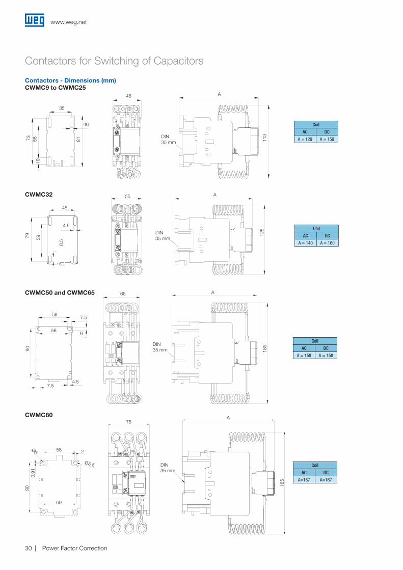
Power Factor Correction 30
Contactors - Dimensions (mm)
Contactors for Switching of Capacitors
CWMC9 to CWMC25
Coil
AC DC
A = 129 A = 159
CWMC32 55
45
79 59
8.5
4.5
A
125 Coil
AC DC
A = 140 A = 160
CWMC50 and CWMC65 66 A
185
90
656
58
4.5
7.5
7.5
Coil
AC DC
A = 158 A = 158
Coil
AC DC
A=167 A=167
CWMC80
66
587.5
7.54.5
656
DIN35 mm
DIN35 mm
A
A55
45
4.5
8.5
79 59
185
75
A
58
60
2
5.5
0.91
90
6
DIN - 35 mm
2Ø6
Ø5.5
58
0.91
90
60
75
DIN35 mm
A
185
185
125
90
DIN35 mm
81
35
10
46
A
113
45
58
A45
35
815810
73 113
46
www.weg.net
Power Factor Correction 31
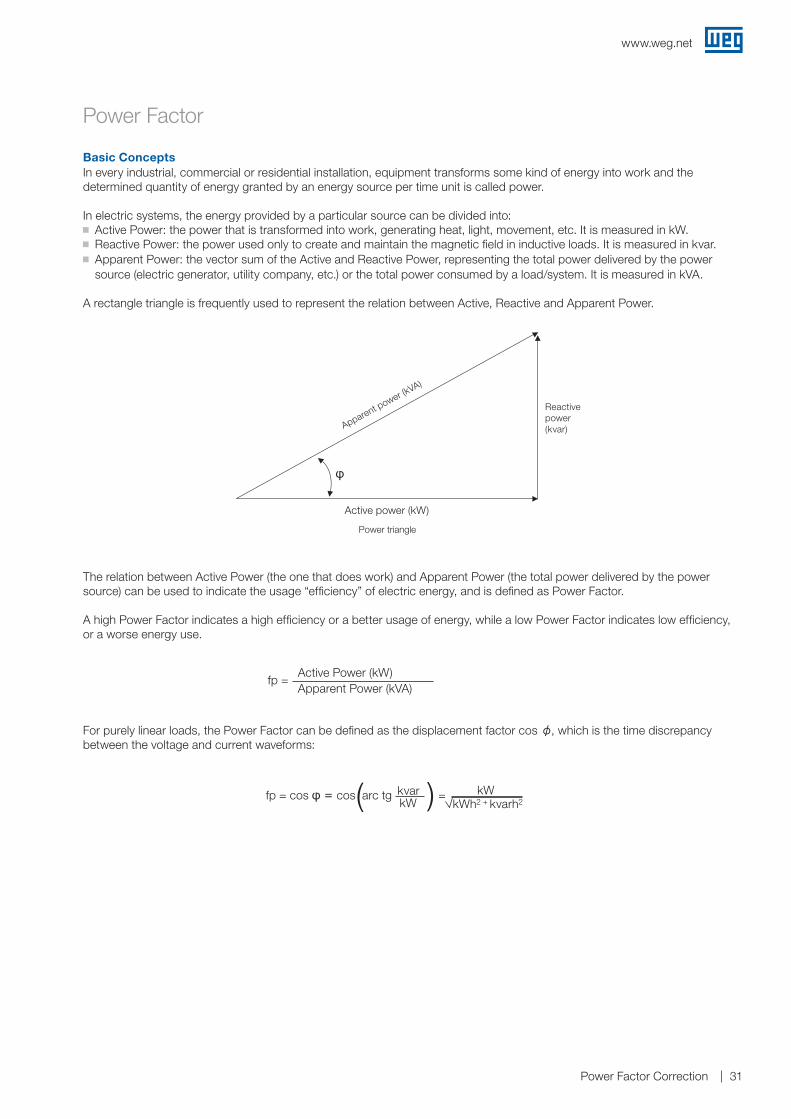
Power Factor
Basic ConceptsIn every industrial, commercial or residential installation, equipment transforms some kind of energy into work and the determined quantity of energy granted by an energy source per time unit is called power.
In electric systems, the energy provided by a particular source can be divided into: J Active Power: the power that is transformed into work, generating heat, light, movement, etc. It is measured in kW. J Reactive Power: the power used only to create and maintain the magnetic field in inductive loads. It is measured in kvar. J Apparent Power: the vector sum of the Active and Reactive Power, representing the total power delivered by the power source (electric generator, utility company, etc.) or the total power consumed by a load/system. It is measured in kVA.
A rectangle triangle is frequently used to represent the relation between Active, Reactive and Apparent Power.
The relation between Active Power (the one that does work) and Apparent Power (the total power delivered by the power source) can be used to indicate the usage “efficiency” of electric energy, and is defined as Power Factor.
A high Power Factor indicates a high efficiency or a better usage of energy, while a low Power Factor indicates low efficiency, or a worse energy use.
For purely linear loads, the Power Factor can be defined as the displacement factor cos φ, which is the time discrepancy between the voltage and current waveforms:
Power triangle
fp = cos φ = cos arc tg = ( )kvar kWkW kWh2 + kvarh2
fp = Active Power (kW)Apparent Power (kVA)
Apparent power (kVA)
Active power (kW)
Reactivepower(kvar)
φ

www.weg.net
Power Factor Correction 32
Power Factor
The cost of the switch and control gear of the equipment grows with the increase of the reactive power. Likewise, to conduct the same active power without the increase of losses, the section of the conductors increases as the power factor decreases. Table 2 shows the variation of the section of the conductor with the power factor. Tit also demnostrates that the required section, supposing a power factor of 0.70, is double the section for a power factor of 1.00.
Causes and Consequences of a Low Power FactorLosses in InstallationThe electric losses occur in the form of heat and are proportional to the square of the total current (I² x R). As this current grows with the increase of reactive power, a relation between the loss increase and low power factor is established causing the heating up on cables and equipment.
Voltage DropsThe increase of current due to the excess of reactive power results in large voltage drops, and may even cause the interruption of the energy supply and overloads in some equipment. Above all, this risk is increased during the periods where the power line is highly required. The voltage drops can also cause the reduction in luminous intensity of lamps and the increase of current in electric motors.
Underuse of Installed CapacityThe overload on the electric installation caused by the reactive energy unables its full use. So, for new loads, further investments have to be made which could be avoided if the power factor had higher levels. The “space” occupied by the reactive energy could be then used for the new loads. The investments on expansion of the electric installation are mainly related to transformers and conductors. The installed transformer must attend the total power of the installed equipment but, due to the presence of reactive power, its capacity must be calculated taking the apparent power into consideration. The table below shows the total power that a transformer must have to attend a load of 800 kW for increasing power factors.
Conductor relative section Power factor
1.00 1.00
1.23 0.9
1.56 0.8
2.04 0.7
2.78 0.6
4.00 0.5
6.25 0.4
11.1 0.3
Active power - kW Power factor Transformer power - kVA
800
0.50 1,600
0.80 1,000
1.00 800
www.weg.net
Power Factor Correction 33
Power Factor
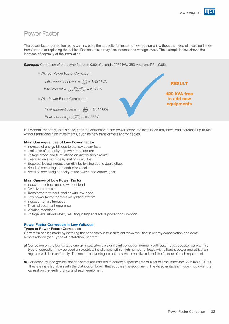
The power factor correction alone can increase the capacity for installing new equipment without the need of investing in new transformers or replacing the cables. Besides this, it may also increase the voltage levels. The example below shows the increase of capacity of the installation.
It is evident, then that, in this case, after the correction of the power factor, the installation may have load increases up to 41%without additional high investments, such as new transformers and/or cables.
Power Factor Correction in Low VoltagesTypes of Power Factor CorrectionCorrection can be made by installing the capacitors in four different ways resulting in energy conservation and cost/benefit relation (see Types of Installation Diagram).
a) Correction on the low voltage energy input: allows a significant correction normally with automatic capacitor banks. This type of correction may be used on electrical installations with a high number of loads with different power and utilization regimes with little uniformity. The main disadvantage is not to have a sensitive relief of the feeders of each equipment.
b) Correction by load groups: the capacitors are installed to correct a specific area or a set of small machines (<7.5 kW / 10 HP). They are installed along with the distribution board that supplies this equipment. The disadvantage is it does not lower the current on the feeding circuits of each equipment.
Main Consequences of Low Power Factor J Increase of energy bill due to the low power factor J Limitation of capacity of power transformers J Voltage drops and fluctuations on distribution circuits J Overload on switch gear, limiting useful life J Electrical losses increase on distribution line due to Joule effect J Need of increasing the conductors section J Need of increasing capacity of the switch and control gear
Main Causes of Low Power Factor J Induction motors running without load J Oversized motors J Transformers without load or with low loads J Low power factor reactors on lighting system J Induction or arc furnaces J Thermal treatment machines J Welding machines J Voltage level above rated, resulting in higher reactive power consumption
Example: Correction of the power factor to 0.92 of a load of 930 kW, 380 V ac and PF = 0.65:
J Without Power Factor Correction:
J With Power Factor Correction:
RESULT
420 kVA free to add new equipmentsP
Initial apparent power =
Initial current =
= 1,431 kVA9300.65
= 2,174 A930.0003 . 380 . 0.65
Final apparent power =
Final current =
= 1,011 kVA9300.92
= 1,536 A930.0003 . 380 . 0.92
www.weg.net
Power Factor Correction 34
M3 -
M3 -
M3 -
M3 -
M3 -
M3 -
M3 -
M3 -
M3 -
M3 -
M3 -
M3 -
Power Factor
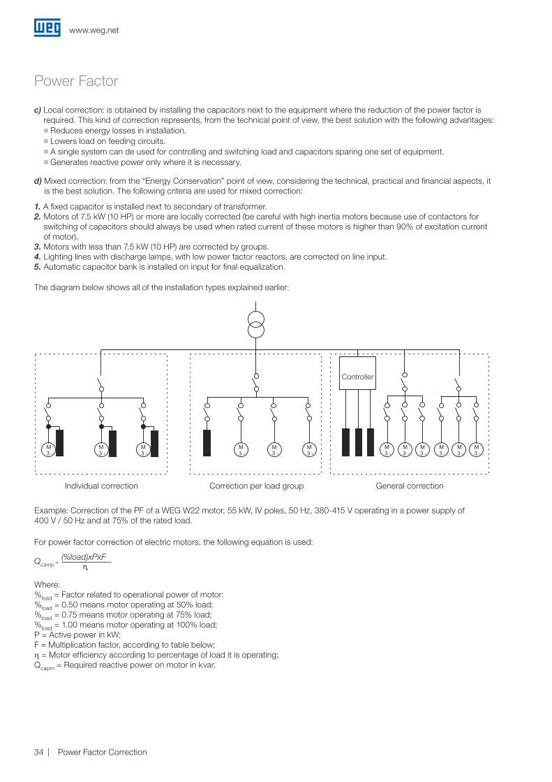
d) Mixed correction: from the “Energy Conservation” point of view, considering the technical, practical and financial aspects, it is the best solution. The following criteria are used for mixed correction:
1. A fixed capacitor is installed next to secondary of transformer.2. Motors of 7.5 kW (10 HP) or more are locally corrected (be careful with high inertia motors because use of contactors for
switching of capacitors should always be used when rated current of these motors is higher than 90% of excitation current of motor).
3. Motors with less than 7.5 kW (10 HP) are corrected by groups.4. Lighting lines with discharge lamps, with low power factor reactors, are corrected on line input.5. Automatic capacitor bank is installed on input for final equalization.
The diagram below shows all of the installation types explained earlier:
Individual correction Correction per load group
Controller
General correction
c) Local correction: is obtained by installing the capacitors next to the equipment where the reduction of the power factor is required. This kind of correction represents, from the technical point of view, the best solution with the following advantages:
J Reduces energy losses in installation. J Lowers load on feeding circuits. J A single system can de used for controlling and switching load and capacitors sparing one set of equipment. J Generates reactive power only where it is necessary.
Where:%load = Factor related to operational power of motor:%load = 0.50 means motor operating at 50% load;%load = 0.75 means motor operating at 75% load;%load = 1.00 means motor operating at 100% load;P = Active power in kW;F = Multiplication factor, according to table below;η = Motor efficiency according to percentage of load it is operating; Qcapm = Required reactive power on motor in kvar.
Qcamp = (%load)xPxF
ɳ
For power factor correction of electric motors, the following equation is used:
Example: Correction of the PF of a WEG W22 motor, 55 kW, IV poles, 50 Hz, 380-415 V operating in a power supply of400 V / 50 Hz and at 75% of the rated load.
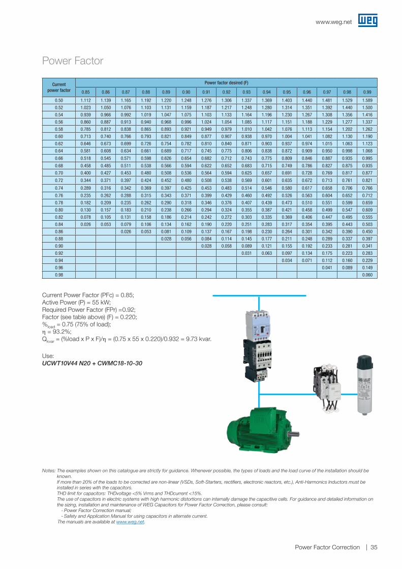
www.weg.net
Power Factor Correction 35
Power Factor
Current Power Factor (PFc) = 0.85;Active Power (P) = 55 kW;Required Power Factor (FPr) =0.92;Factor (see table above) (F) = 0.220;%load = 0.75 (75% of load);η = 93.2%;Qkvar = (%load x P x F)/η = (0.75 x 55 x 0.220)/0.932 = 9.73 kvar.
Use:UCWT10V44 N20 + CWMC18-10-30
Notes: The examples shown on this catalogue are strictly for guidance. Whenever possible, the types of loads and the load curve of the installation should be known. If more than 20% of the loads to be corrected are non-linear (VSDs, Soft-Starters, rectifiers, electronic reactors, etc.), Anti-Harmonics Inductors must be installed in series with the capacitors. THD limit for capacitors: THDvoltage <5% Vrms and THDcurrent <15%. The use of capacitors in electric systems with high harmonic distortions can internally damage the capacitive cells. For guidance and detailed information on the sizing, installation and maintenance of WEG Capacitors for Power Factor Correction, please consult:
- Power Factor Correction manual; - Safety and Application Manual for using capacitors in alternate current.
The manuals are available at www.weg.net.
Current power factor
Power factor desired (F)
0.85 0.86 0.87 0.88 0.89 0.90 0.91 0.92 0.93 0.94 0.95 0.96 0.97 0.98 0.99
0.50 1.112 1.139 1.165 1.192 1.220 1.248 1.276 1.306 1.337 1.369 1.403 1.440 1.481 1.529 1.589
0.52 1.023 1.050 1.076 1.103 1.131 1.159 1.187 1.217 1.248 1.280 1.314 1.351 1.392 1.440 1.500
0.54 0.939 0.966 0.992 1.019 1.047 1.075 1.103 1.133 1.164 1.196 1.230 1.267 1.308 1.356 1.416
0.56 0.860 0.887 0.913 0.940 0.968 0.996 1.024 1.054 1.085 1.117 1.151 1.188 1.229 1.277 1.337
0.58 0.785 0.812 0.838 0.865 0.893 0.921 0.949 0.979 1.010 1.042 1.076 1.113 1.154 1.202 1.262
0.60 0.713 0.740 0.766 0.793 0.821 0.849 0.877 0.907 0.938 0.970 1.004 1.041 1.082 1.130 1.190
0.62 0.646 0.673 0.699 0.726 0.754 0.782 0.810 0.840 0.871 0.903 0.937 0.974 1.015 1.063 1.123
0.64 0.581 0.608 0.634 0.661 0.689 0.717 0.745 0.775 0.806 0.838 0.872 0.909 0.950 0.998 1.068
0.66 0.518 0.545 0.571 0.598 0.626 0.654 0.682 0.712 0.743 0.775 0.809 0.846 0.887 0.935 0.995
0.68 0.458 0.485 0.511 0.538 0.566 0.594 0.622 0.652 0.683 0.715 0.749 0.786 0.827 0.875 0.935
0.70 0.400 0.427 0.453 0.480 0.508 0.536 0.564 0.594 0.625 0.657 0.691 0.728 0.769 0.817 0.877
0.72 0.344 0.371 0.397 0.424 0.452 0.480 0.508 0.538 0.569 0.601 0.635 0.672 0.713 0.761 0.821
0.74 0.289 0.316 0.342 0.369 0.397 0.425 0.453 0.483 0.514 0.546 0.580 0.617 0.658 0.706 0.766
0.76 0.235 0.262 0.288 0.315 0.343 0.371 0.399 0.429 0.460 0.492 0.526 0.563 0.604 0.652 0.712
0.78 0.182 0.209 0.235 0.262 0.290 0.318 0.346 0.376 0.407 0.439 0.473 0.510 0.551 0.599 0.659
0.80 0.130 0.157 0.183 0.210 0.238 0.266 0.294 0.324 0.355 0.387 0.421 0.458 0.499 0.547 0.609
0.82 0.078 0.105 0.131 0.158 0.186 0.214 0.242 0.272 0.303 0.335 0.369 0.406 0.447 0.495 0.555
0.84 0.026 0.053 0.079 0.106 0.134 0.162 0.190 0.220 0.251 0.283 0.317 0.354 0.395 0.443 0.503
0.86 0.026 0.053 0.081 0.109 0.137 0.167 0.198 0.230 0.264 0.301 0.342 0.390 0.450
0.88 0.028 0.056 0.084 0.114 0.145 0.177 0.211 0.248 0.289 0.337 0.397
0.90 0.028 0.058 0.089 0.121 0.155 0.192 0.233 0.281 0.341
0.92 0.031 0.063 0.097 0.134 0.175 0.223 0.283
0.94 0.034 0.071 0.112 0.160 0.229
0.96 0.041 0.089 0.149
0.98 0.060

www.weg.net
Power Factor Correction 36
The Global Solution with electric machines and automation for industry and energy systems.WEG, one of the largest global manufacturers of Electric Motors with Quality and Efficiency recognized in different industrial areas worldwide, is also present in Energy, Transmission and Distribution, Coatings and Industrial Automation sectors, and produces and offers a wide range of electric components for Motor Control and Protection and Electric Circuit Protection.
Motor Protection and Starters J Modular contactors up to 800 A (AC-3) J Compact contactors up to 22 A (AC-3) J Control relays J Motor protective circuit breakers up to 100 A J Enclosed starters (plastic or metallic enclosures) J Customized starters for OEM applications J Overload relays
Electrical Circuit Protection J Miniature circuit breakers up to 125 A J Molded case circuit breakers up to 1,600 A (3P and 4P) J Air circuit breakers up to 6,300 A J D gL-gG fuses up to 63 A J NH gL-gG fuses up to 630 A J NH aR fuses up to 1,000 A J Switch-disconnectors for door or base mounting up to 160 A J Residual current circuit-breaker up to 100 A (30 or 300 mA) J Surge supressors
Electrical Connections J Terminal blocks with screw type connection J Terminal block with spring type connection J Terminal blocks for fuses J Busbar and busbar connectors J Identifiers for terminals and cables J Printing system
Capacitors J Power factor compensation J Lighting J Motor-run
Pushbuttons and Pilot Lights J IP66 pushbuttons and pilot lights J Flush, guarded, extended or mushroom illuminated or non illuminated pushbuttons
J Selector switches lever or knob illuminated or non illuminated or with key
J Emergency pushbuttons (according EN 418) J Contact blocks with “positive break” system J Double pushbutton J Pilot lights with LED technology J Customized descriptions J Decentralized control stations - PBW
Smart Relay J Low voltage electric motor management system J Compact and modular concept J Full motor protection and monitoring through current and voltage measurements
J Multiple operating modes including PLC functions J Easy network module change via exclusive drawer system (Modbus, DeviceNet, Profibus modules)
J USB communication J Free WLP programming software
Electronic Relays J Timing, monitoring and level relays J 22.5 mm width frame J LED for status indication J Multifunction three-phase monitoring relays and timer relays

www.weg.net
Power Factor Correction 37
Global PresenceWith more than 30.000 employees worldwide, WEG is one of the largest electric motors, electronic equipments and systems manufacturers. We are constantly expanding our portfolio of products and services with expertise and market knowledge. We create integrated and customized solutions ranging from innovative products to complete after-sales service.
WEG’s know-how guarantees our Power Factor Correction is the right choice for your application and business, assuring safety, efficiency and reliability.
Partnership is to create solutions that suits your needs
Competitive edge is to unite technology and inovation
Availability is to have a global support network
Global presence is essential, as much as understanding your needs.

www.weg.net
Power Factor Correction 38
Visit: www.weg.net youtube.com/wegvideos
High performance and reliable products to improve your production process.
Know More
Excelence is to provide a whole solution in industrial automation that improves our customers productivity.
www.weg.net
Power Factor Correction 39
Notes

WEG Group - Automation Business Unit Jaraguá do Sul - SC - Brazil Phone: +55 47 3276 4000 [email protected] www.weg.net C
od: 5
003
3846
| R
ev: 0
6 | D
ate
(m/y
): 09
/201
6Th
e va
lues
sho
wn
are
sub
ject
to c
hang
e w
ithou
t prio
r no
tice.
For those countries where there is not a WEG own operation, find our local distributor at www.weg.net.
WEG Worldwide Operations
ARGENTINASan Francisco - CordobaPhone: +54 3564 [email protected]
Cordoba - CordobaPhone: +54 351 [email protected]
Buenos AiresPhone: +54 11 [email protected]
AUSTRALIAScoresby - Victoria Phone: +61 3 [email protected]
AUSTRIAMarkt Piesting - Wiener Neustadt-LandPhone: +43 2633 [email protected]
BELGIUMNivelles - BelgiumPhone: +32 67 [email protected]
BRAZILJaraguá do Sul - Santa CatarinaPhone: +55 47 [email protected]
CHILELa Reina - SantiagoPhone: +56 2 [email protected]
CHINANantong - JiangsuPhone: +86 513 [email protected]
Changzhou – Jiangsu Phone: +86 519 [email protected]
COLOMBIASan Cayetano - BogotaPhone: +57 1 [email protected]
ECUADOREl Batan - QuitoPhone: +593 2 [email protected]
FRANCESaint-Quentin-Fallavier - IsèrePhone: +33 4 [email protected]
GERMANYTürnich - Kerpen Phone: +49 2237 [email protected]
Balingen - Baden-WürttembergPhone: +49 7433 [email protected]
Homberg (Efze) - HessePhone: +49 5681 [email protected]
GHANAAccraPhone: +233 30 [email protected]
INDIABangalore - KarnatakaPhone: +91 80 [email protected]
Hosur - Tamil NaduPhone: +91 4344 [email protected]
ITALYCinisello Balsamo - MilanoPhone: +39 2 [email protected]
JAPANYokohama - KanagawaPhone: +81 45 [email protected]
MALAYSIAShah Alam - SelangorPhone: +60 3 [email protected]
MEXICOHuehuetoca - MexicoPhone: +52 55 [email protected]
Tizayuca - HidalgoPhone: +52 77 97963790
NETHERLANDSOldenzaal - OverijsselPhone: +31 541 [email protected]
PERULa Victoria - LimaPhone: +51 1 [email protected]
PORTUGALMaia - PortoPhone: +351 22 [email protected]
RUSSIA and CISSaint PetersburgPhone: +7 812 363 [email protected]
SOUTH AFRICAJohannesburgPhone: +27 11 [email protected]
SPAINCoslada - MadridPhone: +34 91 [email protected]
SINGAPORESingaporePhone: +65 [email protected]
SingaporePhone: +65 [email protected]
SCANDINAVIAMölnlycke - SwedenPhone: +46 31 [email protected]
UKRedditch - WorcestershirePhone: +44 1527 [email protected]
UNITED ARAB EMIRATESJebel Ali - DubaiPhone: +971 4 [email protected]
USADuluth - GeorgiaPhone: +1 678 [email protected]
Minneapolis - MinnesotaPhone: +1 612 3788000
VENEZUELAValencia - CaraboboPhone: +58 241 [email protected]