automation control development with capstone projectsijme.us/cd_06/pdf/ent p501-115.pdf ·...
TRANSCRIPT

Proceedings of The 2006 IJME – INTERTECH Conference
Session: ENT P501- 115
Automation Control Development with Capstone Projects
Cheng Y. Lin, PhD. Steve Hsiung, PhD.
Engineering Technology Department
Old Dominion University [email protected]
[email protected] I. Abstract This article presents the development of the automation control projects developed in the Mechanical Engineering Technology Program of the Engineering Technology Department at Old Dominion University. These capstone projects are designed to help students gain industrial application experiences on design, test, and implementation. Two projects on automation controls are the focus of this article: (1) an automatic ship-bottom blasting machine and (2) a fully automated Car Jack. Three major topics are presented in each project: (1) introduction of the background, (2) methods to solve the problems in mechanical designs and automation controls such as hydraulic circuit and/or PLC programming, and (3) implementation and test results. II. Introduction The course objectives of Automation and Controls that offered in the Mechanical Engineering Technology Program of the Department of Engineering Technology at Old Dominion University are:
(1) Pneumatic components and pneumatic circuit designs. (2) Feedbacks from electrical sensors and related ladder diagrams. (3) Introduction to Programmable Logical Controllers (PLC) and PLC [1],[2] programming. (4) Integration of pneumatic, electrical, and/or hydraulic components with PLC programming controls.
To ensure students have hands-on experiences in this course, a two-hour/week lab is also required to teach the students with integrate mechanical, pneumatic, and electrical components in ladder diagrams and PLC programming. Basically, the lab includes three main sessions: (1) four weeks of pneumatic applications, (2) four weeks of pneumatic components, electrical sensors, and ladder diagrams, and (3) five weeks of PLC programming using IDEC [3] and TRiLOGI [4] PLCs. In addition, the simulation software of Automation Studio [5] is also used in each project so that students can check their designs before the actual implementation. Depending on the

Proceedings of The 2006 IJME – INTERTECH Conference
number of students enrolled in each lab, several small groups are formed as teams for each assignment. The following steps are adopted to effectively manage the lab activities:
(1) Implementation of the floor plan. (2) Management of the components. (3) Use of Automation Studio. (4) Use of TRiLOGI and IDEC PLC controllers.
III. Senior Capstone Projects
Senior mechanical engineering technology students are required to define/research their senior capstone projects. Usually, the projects come from a variety of sources that include specific tasks given by the instructor of the capstone course, tasks requested by local industry or members of the industrial advising committee, projects needed from the student’s work place, or simply the ideas developed by students. The project is a perfect opportunity for students to work in a team to initiate a “real world” application design that requires certain levels of efforts to meet senior capstone project criteria. The faculty members who work on the project served as the students’ faculty advisors of the course. In this article, two senior capstone projects in automation control areas are presented: (1) an automatic ship-bottom blasting machine and (2) an automatic Car Jack design. The reason to present these two projects is because they make a significant contribution to improve working environment, increase efficiency, boost productivity, and enhance safety. 1. Automation Ship Bottom Blasting Machine Ships’ hulls require periodic cleaning due to corrosion, paint degradation, and incrustation with marine growth such as barnacles. To access the hulls, a ship must first be positioned on several equally spaced position blocks, located on the floor of a sunken dry dock. The water is then pumped out from the dry dock, where the blocks will be raised to support the ship.
Normally, workers perform the cleaning with blasting hoses. On an average calculation, one person can blast around 100 to 200 ft2/hr with approximately one-half ton of abrasive particles being deposited on the floor of the dry dock [1]. The operation is very intense and the cleaning of abrasive particles and incrustation slows down the cleaning process. In addition, the space is limited between the hulls and the floor of the dry dock. The supporting blocks are impedimental to personnel and cleaning equipment. Vast amounts of potentially harmful dust are generated, so other workers are excluded from the vicinity of the blasting process. Therefore, an automatic blasting machine is designed to solve this particular problem. Several current blasting machines [2],[3],[4],[5] were studied before the implementation of the final design. 1.1 The Blasting System Figure 1 shows the principle of the blasting process used in this design. The abrasive particles are fed into a high RPM wheel (Part 1), which is driven by a 30-HP motor (Part 2) with 3450 RPM. The wheel projects the abrasive centrifugally at a speed of 177 ft/s toward the surface to be blasted. Rubber seals between the blast machine and hull ensure that all the abrasive, dust, and paint chips from the blast process are directed back into the machine. A strong jet of air
Proceedings of The 2006 IJME – INTERTECH Conference
(Part 4) is directed through the stream of the falling abrasive. The heavy abrasive particles continue to fall, but the lighter dust and paint is carried by the air stream through a duct (Part 5) into a dust collector. The dust can be periodically emptied and the abrasive particles can be recycled through an auger (Part 6) to the centrifugal wheel.
Figure 1: Machine blasting process.
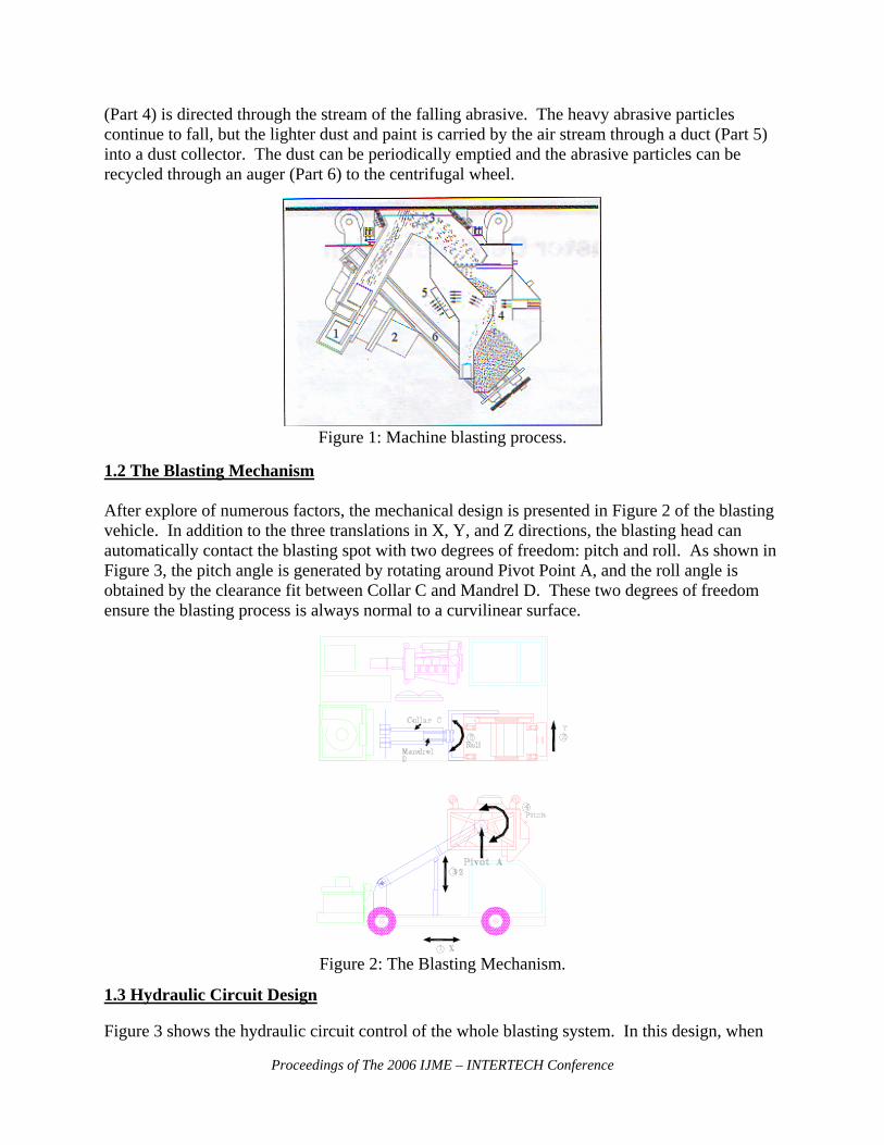
1.2 The Blasting Mechanism After explore of numerous factors, the mechanical design is presented in Figure 2 of the blasting vehicle. In addition to the three translations in X, Y, and Z directions, the blasting head can automatically contact the blasting spot with two degrees of freedom: pitch and roll. As shown in Figure 3, the pitch angle is generated by rotating around Pivot Point A, and the roll angle is obtained by the clearance fit between Collar C and Mandrel D. These two degrees of freedom ensure the blasting process is always normal to a curvilinear surface.
Figure 2: The Blasting Mechanism.
1.3 Hydraulic Circuit Design Figure 3 shows the hydraulic circuit control of the whole blasting system. In this design, when

Proceedings of The 2006 IJME – INTERTECH Conference
the contact pressure between blasting head and hull is too high, the fluid will be drained to the hydraulic tank through a use of the adjustable regulated valve. Besides, when hydraulic power is suddenly cut off, the lifting mechanism and vehicle wheels will remain at its position to keep the whole system intact. This design also ensures the speeds of lifting cylinder, blasting motor, and wheel motors adjustable. Simulation software [6] of Automation Studio was used in this design process.
Figure 3: Hydraulic Circuit for the Blasting Mechanism.
1.4 Implantation and Results Figure 4 presents the blasting vehicle when the blasting head is raised at its highest position. Figure 5 shows the bottom blasting of the machine with a moving speed of 20 ft/minute. When performing the blasting process, only one person, the driver of the vehicle, is needed. Figure 6 shows the side blasting of the vehicle. When compared to the open blasting process operated by workers, this automation process drastically reduces the costs of man-hours and abrasive consumption, this reduces the total blasting cost. It also improves the working condition of the workers by decreasing the dusty atmosphere, which is a constant issue in the current industry practice of open blasting. The efficiency and environmental friendly features have awarded this invention with an US patent [7].
Figure 4: The Blasting Machine

Proceedings of The 2006 IJME – INTERTECH Conference
Figure 5: Bottom Blasting
2. Automated Car Jack The purpose of this project is to analyze the situations of a standard electric Car Jack and use mechanical and electrical designs to solve potential problems. After the analysis of the Car Jack conditions, a turnkey process is created to resolve the problems. In this study, a programmable logic controller (PLC) is used to control several sensors to perform the needed functions. This project design process includes: (1) list problems of a current electric Car Jack, (2) present a solution for the problems, and (3) fabricate and test the design [8]. 2.1 Problems of the Standard Electric Car Jacks Figure 7 presents a standard electric Car Jack currently available in the market. Three main problems are discovered when operating this Car Jack: (1) unstable footing, (2) limited lifting space, and (3) difficulty in locating the lift position. In problem #1, it may not always be possible to stop the vehicle on a leveled base for necessary inspection or repair during an emergency stop or break down at a road side. For example, the shoulder of a highway does not provide a surface that allows a vehicle to be properly lifted with a standard screw-driven or scissor-lift Car Jack. The uneven surface will not provide an adequate base for the Car Jack to rest on. This poses an immediate safety issue. As noted in Figure 7, this potentially uneven ground is where the pavement meets the grass shoulder area.
Figure 6: Side Blasting

Proceedings of The 2006 IJME – INTERTECH Conference
Figure 7: Standard Electric Car Jack
In problem #2, the small feet contact of the Car Jack provides less stable on uneven ground, especially when the road side surface is not hard or strong enough to support the lifted weight. This type of footing is also illustrated in Figure 7. As shown in Figure 8, problem #3 is the low ground clearance to locate a proper position under the vehicle to place the Car Jack. In locating the Car Jack lift position, it is often necessary to prone or lay on one’s back toward/on the ground to find the lift spot under the vehicle. In most small cars and vans there is very little clearance between the vehicle and the ground. This adds difficulties of locating the exact placement of the Car Jack. Another potential problem in this case is that some people may have physical limitations prevent this type of action. 2.2 The Modified Automated Car Jack Figure 9 shows the complete assembly of the automated Car Jack design. A wood base mounted under the Car Jack is applied to solve Problem #1 mentioned in the previous section. To make this Car Jack fully automated, Table 1 shows several inputs and outputs used in the PLC program. In this programming, Start and Reset buttons are used to start and stop the whole system respectively. In-Position Limit Switch is to locate a proper jack location. A limit switch is served for sensing the level of the Car Jack system. This switch is mounted on the top of the Car Jack (Figure 9). When a wrong position is contacted, the switch will be activated and the motion of the Car Jack will be reversed. Limit Max and Limit Min switches are used to stop the system when the Car Jack reaches either the highest or lowest position. The Coded Magnetic Switch is used to activate a timer which will keep the lifting motion even when the top of the Car Jack contacts the lifting position so that the tire can be completed raised and freely rotated. Figure 10 presents a portion of the PLC program. 2.3 Implementation and Results This project has successfully eradicated all of the drawbacks of a standard manually operated screw-type Car Jack. By automating the system, this product has created a new innovation for the future of the Car
POTENTIAL UNEVEN SURFACE
SMALL FEET PROVIDES LESS STABILTY ON UNEVEN GROUND

Proceedings of The 2006 IJME – INTERTECH Conference
Jack. This product has effectively eliminated the unnecessary kneeling or crouching in an attempt to locate the proper lifting position. Implementing a coded magnetic switch into the design, the operator will no longer need to bend over to position the jack in its correct lifting position. The addition of the limit switches also provides the needed position indication, if the jack is out of location. It simply will not operate in such a case. However, the total cost of this automation Car Jack is higher than a standard manually-operated Car Jack. This is because of the expenses of a PLC, sensors, and a motor, but the safety and convenience will justify the additional cost.
Figure 8: Vehicle Ground Clearance
Figure 9: The Automated Car Jack
LOW GROUND CLEARANCE

Proceedings of The 2006 IJME – INTERTECH Conference
Table 1: PLC I/O CControls Inputs Outputs
Start Button I 1.0
Motor Control Up O 0.1
Reset Button I 2.0
Motor Control Down O 0.2
In-Position Limit Switch I 3.0
LED In Position O 0.3
Limit Max I 4.0
LED Power/Moving O 0.4
Limit Min I 5.0 N/A
Coded Magnetic Switch I 6.0 N/A
IV. Summary Two senior capstone projects were presented to help students gain design experience on automation control. In the first project, the automation process drastically reduces the costs of man-hours, abrasive consumption, and total blasting cost used by manually operated blasting operation. It also improves the working condition of the workers by decreasing the dusty atmosphere, which is experiencing difficulties in the current open blasting process. This new project invention assisted students’ knowledge of the design experience on machine design, hydraulic circuit system, and mechanism control. This particular project invention had a headline on the local newspaper and awarded an US pattern. In the second project, the automation of a standard Car Jack not only simplified the operation of a manually operated Car Jack, but also increases the stability and safety. This project helped students experience the mechanical and electrical system designs, the PLC control programming, system fabrication, and testing.
Figure 10: Portion of the PLC Program
V. Bibliography [1] Ambrose, G. C. III, Fox, T., Ketz, E., Lin, C., Porter, F., Wells, S., “CASRM Bottom Blaster Demonstration.” CASRM Report, January 1997.

Proceedings of The 2006 IJME – INTERTECH Conference
[2] Bergh, John C., “Convertible Blast Cleaning Unit” US Patent No: 4020959, December, 1975. [3] Hocket, W. B., “Universal Abrasive Cleaning Apparatus” US Patent No: 44545156, April 1984. [4] Jurohiji, S., Shigyo, G., Arai, N., “Mobile Shot Blasting Apparatus for Shot Blasting the Bottom of a Ship or the Like” US Patent No: 4092942, July 1977. [5] Shelton, J. J., “Blasting Machine with Position Sensing and Adjustments” US Patent No: 4286417, August 1979. [6] Automation Studio, Retrieved February 12, 2006, from www.automationstudio.com. [7] Fox T.J., Ambrose, L.W., Brown, Jr, K.G., Curtis, G.H., Ketz, Jr, E.J., Lin, C.Y., Porter F.H., and Wells, S.C., “Apparatus for Abrasive Blasting of Ship Bottoms; Method and Apparatus for Testing Blasted Surfaces” US Patent No: 5938509, August 1999. [8] Walls, C.B., Long, A.Z., “Automated Car Jack”, Senior Project Report, Department of Engineering Technology, Old Dominion University, April, 2006. VI. Biography CHENG Y LIN is an associate professor of Engineering Technology at Old Dominion University. Dr. Lin is a registered Professional Engineer of Virginia. He teaches Machine Design, CAD, CNC, and Robotics and is active in local industrial research and consultation. He earned his B.S. and M.S. degrees of Mechanical Engineering from National Cheng-Kung University in 1975 and 1977 and a Ph.D. of Mechanical Engineering from Texas A&M University in 1989. STEVE C. HSIUNG is an associate professor of Electrical Engineering Technology at Old Dominion University. Prior to his current position, Dr. Hsiung had worked for Maxim Integrated Products, Inc., Seagate Technology, Inc., and Lam Research Corp., all in Silicon Valley, CA. Dr. Hsiung also taught at Utah State University and California University of Pennsylvania. He earned his BS degree from National Kauhsiung Normal University in 1980, MS degrees from University of North Dakota in 1986 and Kansas State University in 1988, and PhD degree from Iowa State University in 1992.