automation & enterprise mobility - bartec · automation & enterprise mobility. automation...
TRANSCRIPT
AUTOMATION & ENTERPRISE MOBILITY


AUTOMATION
HUMAN MACHINE INTERFACE
BUS TECHNOLOGY
ENTERPRISE MOBILITY
INDUSTRY TABLETS/TABLET PCS
MOBILE CAMERA SYSTEMS/SMARTPHONES
TOUCH COMPUTER/MOBILE COMPUTER
DATA CAPTURE
AUTOMATION & ENTERPRISE MOBILITY
1
2


HUMAN MACHINE INTERFACE


CONTENT
POLARIS PROFESSIONAL
Overview device series POLARIS SMART HMI and POLARIS PROFESSIONAL 8 - 9
POLARIS SMART HMI 7" W 17-71V6-1.../0.00
14 - 15
POLARIS Panel PC 10.4" 17-71V1-90../.0000.00
16 - 17
POLARIS Panel PC 12.1" 17-71V1-80../.0000.00
18 - 19
POLARIS Panel PC 12.1" W 17-71V1-B.../.0000.00
20 - 21
POLARIS Panel PC 15" 17-71V1-.0../.000..00
22 - 23
POLARIS Panel PC 15" Sunlight 17-71V1-.2../.000..00
24 - 25
POLARIS Panel PC 17.3" W 17-71V1-.0../.000..00
26 - 27
POLARIS Panel PC 19.1" 17-71V1-.0../.000..00
28 - 29
POLARIS Panel PC 24" W 17-71V1-.0../.000..00
30 - 31
POLARIS II Panel PC 19.1" 17-72V4-...2/..00
32 - 33
POLARIS II Panel PC 22" W 17-72V4-...2/..00
34 - 35
POLARIS II Panel PC 24" W 17-7.V4-8..2/..00
36 - 37
Smart Tastatur for POLARIS SMART HMI 7" W 17-71VZ-C011
38
Ex i memory stick for POLARIS SMART HMI 7" W 17-A1Z0-0007
38
USB Smart Devices Bluetooth 17-71VZ-A020 WLAN 17-71VZ-A010
39
Input devices for POLARIS PROFESSIONAL 17-71VZ-40.0; 17-71VZ-.000
40 - 41
Enclosure for mouse and keyboard POLARIS PROFESSIONAL 05-0041-0277
40
Accessories for POLARIS PROFESSIONAL 02-..; 04-..; 05-..; 07-..; 17-..
42 - 45

INHALT
POLARIS REMOTE
Overview device series POLARIS REMOTE and POLARIS REMOTE ZeroClient 10 - 11
POLARIS Remote 15" 17-71V2-.0../00.0
46 - 47
POLARIS Remote 15" Sunlight 17-71V2-.0../00.0
48 - 49
POLARIS Remote 19.1" 17-71V2-.0../00.0
50 - 51
POLARIS Remote 24" W 17-71V2-.0../00.0
52 - 53
POLARIS ZeroClient 12.1" W 17-71V1-B436/Z000
54 - 55
POLARIS ZeroClient 15" 17-71V1-.072/Z000/.200
56 - 57
POLARIS ZeroClient 15" Sunlight 17-71V1-6272/Z000/.200
58 - 59
POLARIS ZeroClient 17.3" W 17-71V1-.072/Z000/.200
60 - 61
POLARIS ZeroClient 19.1" 17-71V1-.072/Z000/.200
62 - 63
POLARIS ZeroClient 24" W 17-71V1-.072/Z000/.200
64 - 65
POLARIS II Remote 19.1" 17-7.V5-..0./..00
66 - 67
POLARIS II Remote 22" W 17-7.V5-..0./..00
68 - 69
POLARIS II Remote 24" W 17-7.V5-8.0./..00
70 - 71
Input devices for POLARIS REMOTE 17-71VZ-40.0; 17-71VZ-.000
72 - 73
Enclosure for mouse and keyboard for POLARIS REMOTE 05-0041-0277
72
Accessories for POLARIS REMOTE 02-..; 03-..; 04-..; 05-..
74 - 77

INHALT
POLARIS COMFORT
Overview device series POLARIS COMFORT 12
POLARIS Touch Panel 5.7" 17-71V1-A0../X000
78 - 79
POLARIS Touch Panel 10.4" 17-71V1-90../X000
80 - 81
POLARIS Touch Panel 12.1" 17-71V1-80../X000
82 - 83
Visualisation software BMS-Graf-pro 7 17-28TF-0075
84
Input devices for POLARIS COMFORT 17-71VZ-.000
85
Accessories for POLARIS COMFORT 02-..; 04-..; 05-..; 07-..; 17-..
86 - 87
POLARIS BASIC
Overview device series POLARIS BASIC 13
POLARIS Control 17-71V0-000.
88 - 89
POLARIS Panel PC 5.7" 17-71V1-10..
90 - 91
POLARIS Panel PC 10.4" 17-71V1-20..
92 - 93
POLARIS Panel PC 12.1" 17-71V1-30..
94 - 95
Visualisation software BMS-Graf-pro 6 17-28TF-0071/0.00
96
Accessories for POLARIS BASIC 04-..; 05-..; 07-..; 17-..
97 - 98
03-0330-0648-10/2017-BAT-317215/7BARTEC8
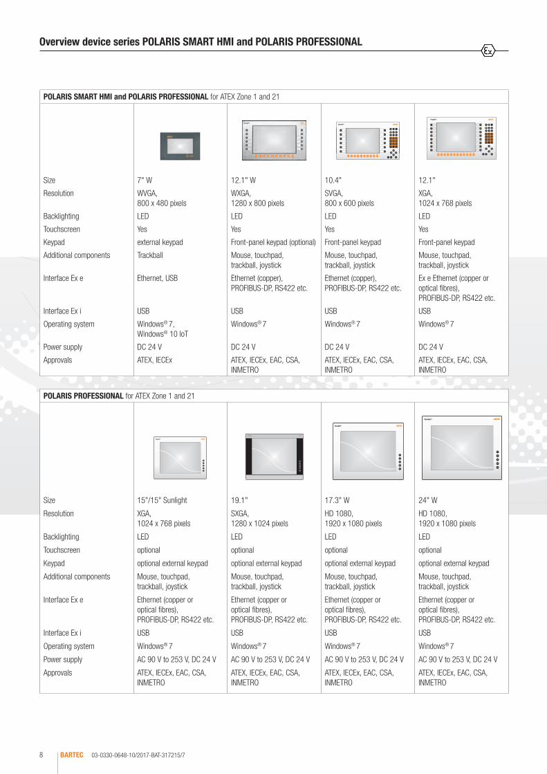
Overview device series POLARIS SMART HMI and POLARIS PROFESSIONAL
POLARIS SMART HMI and POLARIS PROFESSIONAL for ATEX Zone 1 and 21
Size 7" W 12.1" W 10.4" 12.1"
Resolution WVGA, 800 x 480 pixels
WXGA, 1280 x 800 pixels
SVGA, 800 x 600 pixels
XGA, 1024 x 768 pixels
Backlighting LED LED LED LED
Touchscreen Yes Yes Yes Yes
Keypad external keypad Front-panel keypad (optional) Front-panel keypad Front-panel keypad
Additional components Trackball Mouse, touchpad, trackball, joystick
Mouse, touchpad, trackball, joystick
Mouse, touchpad, trackball, joystick
Interface Ex e Ethernet, USB Ethernet (copper), PROFIBUS-DP, RS422 etc.
Ethernet (copper), PROFIBUS-DP, RS422 etc.
Ex e Ethernet (copper or optical fibres), PROFIBUS-DP, RS422 etc.
Interface Ex i USB USB USB USB
Operating system Windows® 7, Windows® 10 IoT
Windows® 7 Windows® 7 Windows® 7
Power supply DC 24 V DC 24 V DC 24 V DC 24 V
Approvals ATEX, IECEx ATEX, IECEx, EAC, CSA, INMETRO
ATEX, IECEx, EAC, CSA, INMETRO
ATEX, IECEx, EAC, CSA, INMETRO
POLARIS PROFESSIONAL for ATEX Zone 1 and 21
Size 15"/15" Sunlight 19.1" 17.3" W 24" W
Resolution XGA, 1024 x 768 pixels
SXGA, 1280 x 1024 pixels
HD 1080, 1920 x 1080 pixels
HD 1080, 1920 x 1080 pixels
Backlighting LED LED LED LED
Touchscreen optional optional optional optional
Keypad optional external keypad optional external keypad optional external keypad optional external keypad
Additional components Mouse, touchpad, trackball, joystick
Mouse, touchpad, trackball, joystick
Mouse, touchpad, trackball, joystick
Mouse, touchpad, trackball, joystick
Interface Ex e Ethernet (copper or optical fibres), PROFIBUS-DP, RS422 etc.
Ethernet (copper or optical fibres), PROFIBUS-DP, RS422 etc.
Ethernet (copper or optical fibres), PROFIBUS-DP, RS422 etc.
Ethernet (copper or optical fibres), PROFIBUS-DP, RS422 etc.
Interface Ex i USB USB USB USB
Operating system Windows® 7 Windows® 7 Windows® 7 Windows® 7
Power supply AC 90 V to 253 V, DC 24 V AC 90 V to 253 V, DC 24 V AC 90 V to 253 V, DC 24 V AC 90 V to 253 V, DC 24 V
Approvals ATEX, IECEx, EAC, CSA, INMETRO
ATEX, IECEx, EAC, CSA, INMETRO
ATEX, IECEx, EAC, CSA, INMETRO
ATEX, IECEx, EAC, CSA, INMETRO

03-0330-0648-10/2017-BAT-317215/8 BARTEC 9
1
Types of fasteningfor ATEX Zone 1 and 21
Types of fastening forATEX Zone 2, ATEX Zone 21 and 22
Overview device series POLARIS PROFESSIONAL
POLARIS PROFESSIONAL für ATEX Zone 2 und ATEX Zone 21/22
Size 19.1" 22" W 24" W
Resolution SXGA, 1280 x 1024 pixels
WSXGA+, 1680 x 1050 pixels
Full HD, 1920 x 1080 pixels
Backlighting LED LED LED
Touchscreen optional optional optional
Keypad optional external keypad optional external keypad optional external keypad
Additional components Touchpad, trackball Touchpad, trackball Touchpad, trackball
Interface Ex e Ethernet (copper or optical fibres), PROFIBUS-DP, RS422 etc.
Ethernet (copper or optical fibres), PROFIBUS-DP, RS422 etc.
Ethernet (copper or optical fibres), PROFIBUS-DP, RS422 etc.
Data transfer Ethernet, serial Ethernet, serial Ethernet, serial
Power supply AC 90 V to 253 V, DC 24 V
AC 90 V to 253 V, DC 24 V
AC 90 V to 253 V, DC 24 V
Approvals ATEX, EAC ATEX, EAC ATEX, EAC

03-0330-0648-07/2014-BAT-317215/11BARTEC10
Types of fastening for ATEX Zone 1 and 21
POLARIS REMOTE for ATEX Zone 1 and 21
Size 15"/15" Sunlight 19.1" 24" W
Resolution XGA, 1024 x 768 pixels SXGA, 1280 x 1024 pixels Full HD 1080, 1920 x 1080 pixels
Backlighting LED LED LED
Touchscreen optional optional optional
Keypad optional external keypad optional external keypad optional external keypad
Additional components Mouse, touchpad, trackball, joystick Mouse, touchpad, trackball, joystick Mouse, touchpad, trackball, joystick
Interface KVM Box VGA/PS2 or DVI/USB VGA/PS2 or DVI/USB DVI/USB
Data transfer CAT7/Optical fibres CAT7/Optical fibres CAT7/Optical fibres
Power supply AC 90 V to 253 V, DC 24 V AC 90 V to 253 V, DC 24 V AC 90 V to 253 V, DC 24 V
Approvals ATEX, IECEx, EAC, CSA, INMETRO ATEX, IECEx, EAC, CSA, INMETRO ATEX, IECEx, EAC, CSA, INMETRO
POLARIS REMOTE for ATEX Zone 2 and ATEX Zone 21/22
Size 19.1" 22" W 24" W
Resolution SXGA, 1280 x 1024 pixels WSXGA+, 1680 x 1050 pixels Full HD, 1920 x 1080 pixels
Backlighting LED LED LED
Touchscreen optional optional optional
Keypad optional external keypad optional external keypad optional external keypad
Additional components Touchpad, trackball Touchpad, trackball Touchpad, trackball
Interface KVM Box 1 x Keyboard in, 1 x Monitor in, 1 x Monitor out
1 x Keyboard in, 1 x Monitor in, 1 x Monitor out
1 x Keyboard in, 1 x Monitor in, 1 x Monitor out
Data transfer CAT7/Optical fibres CAT7/Optical fibres CAT7/Optical fibres
Power supply AC 90 V to 253 V, DC 24 V AC 90 V to 253 V, DC 24 V AC 90 V to 253 V, DC 24 V
Approvals ATEX, EAC ATEX, EAC ATEX, EAC
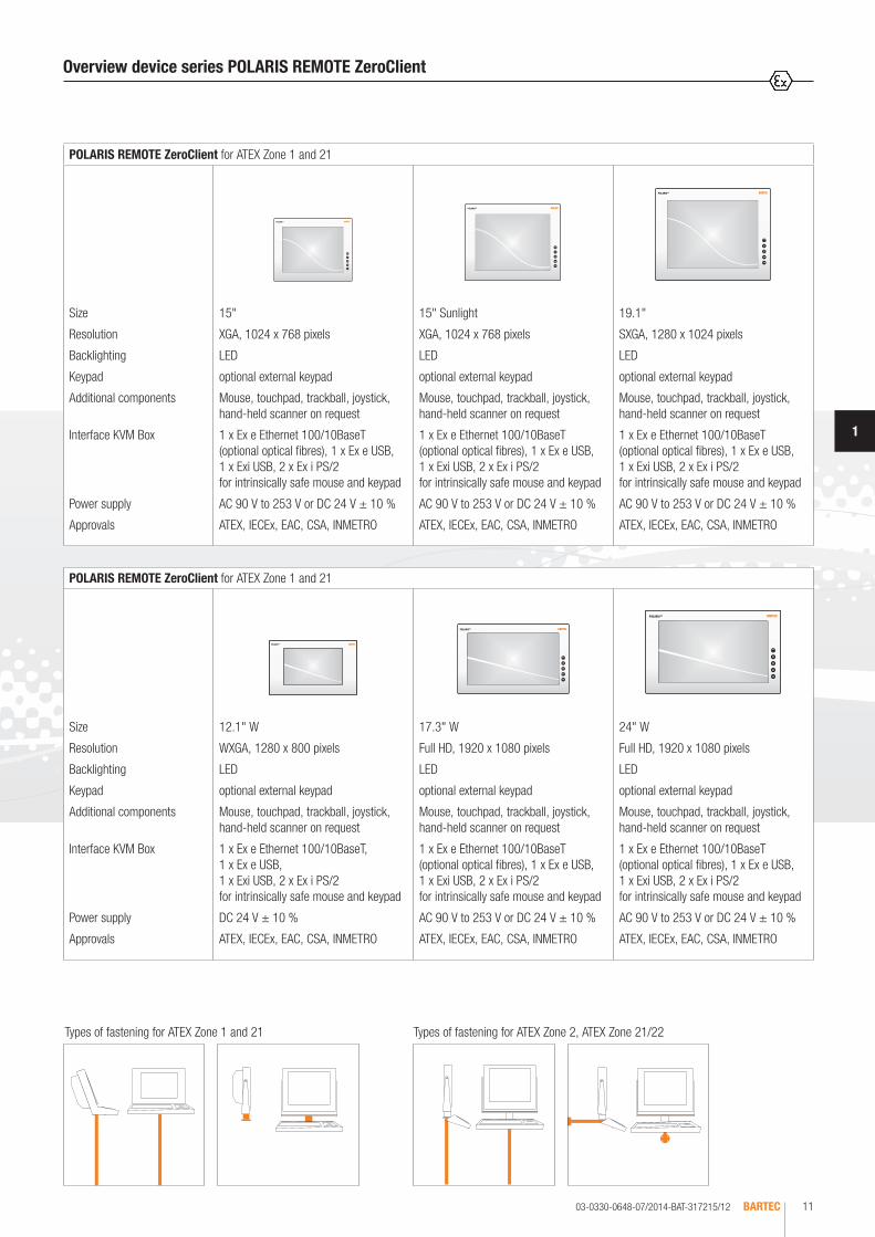
Overview device series POLARIS REMOTE
03-0330-0648-07/2014-BAT-317215/12 BARTEC 11
1
Types of fastening for ATEX Zone 1 and 21 Types of fastening for ATEX Zone 2, ATEX Zone 21/22
POLARIS REMOTE ZeroClient for ATEX Zone 1 and 21
Size 15" 15" Sunlight 19.1"
Resolution XGA, 1024 x 768 pixels XGA, 1024 x 768 pixels SXGA, 1280 x 1024 pixels
Backlighting LED LED LED
Keypad optional external keypad optional external keypad optional external keypad
Additional components Mouse, touchpad, trackball, joystick, hand-held scanner on request
Mouse, touchpad, trackball, joystick, hand-held scanner on request
Mouse, touchpad, trackball, joystick, hand-held scanner on request
Interface KVM Box 1 x Ex e Ethernet 100/10BaseT (optional optical fibres), 1 x Ex e USB, 1 x Exi USB, 2 x Ex i PS/2 for intrinsically safe mouse and keypad
1 x Ex e Ethernet 100/10BaseT (optional optical fibres), 1 x Ex e USB, 1 x Exi USB, 2 x Ex i PS/2 for intrinsically safe mouse and keypad
1 x Ex e Ethernet 100/10BaseT (optional optical fibres), 1 x Ex e USB, 1 x Exi USB, 2 x Ex i PS/2 for intrinsically safe mouse and keypad
Power supply AC 90 V to 253 V or DC 24 V ± 10 % AC 90 V to 253 V or DC 24 V ± 10 % AC 90 V to 253 V or DC 24 V ± 10 %
Approvals ATEX, IECEx, EAC, CSA, INMETRO ATEX, IECEx, EAC, CSA, INMETRO ATEX, IECEx, EAC, CSA, INMETRO
POLARIS REMOTE ZeroClient for ATEX Zone 1 and 21
Size 12.1" W 17.3" W 24" W
Resolution WXGA, 1280 x 800 pixels Full HD, 1920 x 1080 pixels Full HD, 1920 x 1080 pixels
Backlighting LED LED LED
Keypad optional external keypad optional external keypad optional external keypad
Additional components Mouse, touchpad, trackball, joystick, hand-held scanner on request
Mouse, touchpad, trackball, joystick, hand-held scanner on request
Mouse, touchpad, trackball, joystick, hand-held scanner on request
Interface KVM Box 1 x Ex e Ethernet 100/10BaseT, 1 x Ex e USB, 1 x Exi USB, 2 x Ex i PS/2 for intrinsically safe mouse and keypad
1 x Ex e Ethernet 100/10BaseT (optional optical fibres), 1 x Ex e USB, 1 x Exi USB, 2 x Ex i PS/2 for intrinsically safe mouse and keypad
1 x Ex e Ethernet 100/10BaseT (optional optical fibres), 1 x Ex e USB, 1 x Exi USB, 2 x Ex i PS/2 for intrinsically safe mouse and keypad
Power supply DC 24 V ± 10 % AC 90 V to 253 V or DC 24 V ± 10 % AC 90 V to 253 V or DC 24 V ± 10 %
Approvals ATEX, IECEx, EAC, CSA, INMETRO ATEX, IECEx, EAC, CSA, INMETRO ATEX, IECEx, EAC, CSA, INMETRO
Overview device series POLARIS REMOTE ZeroClient
03-0330-0648-10/2017-BAT-317215/13BARTEC12
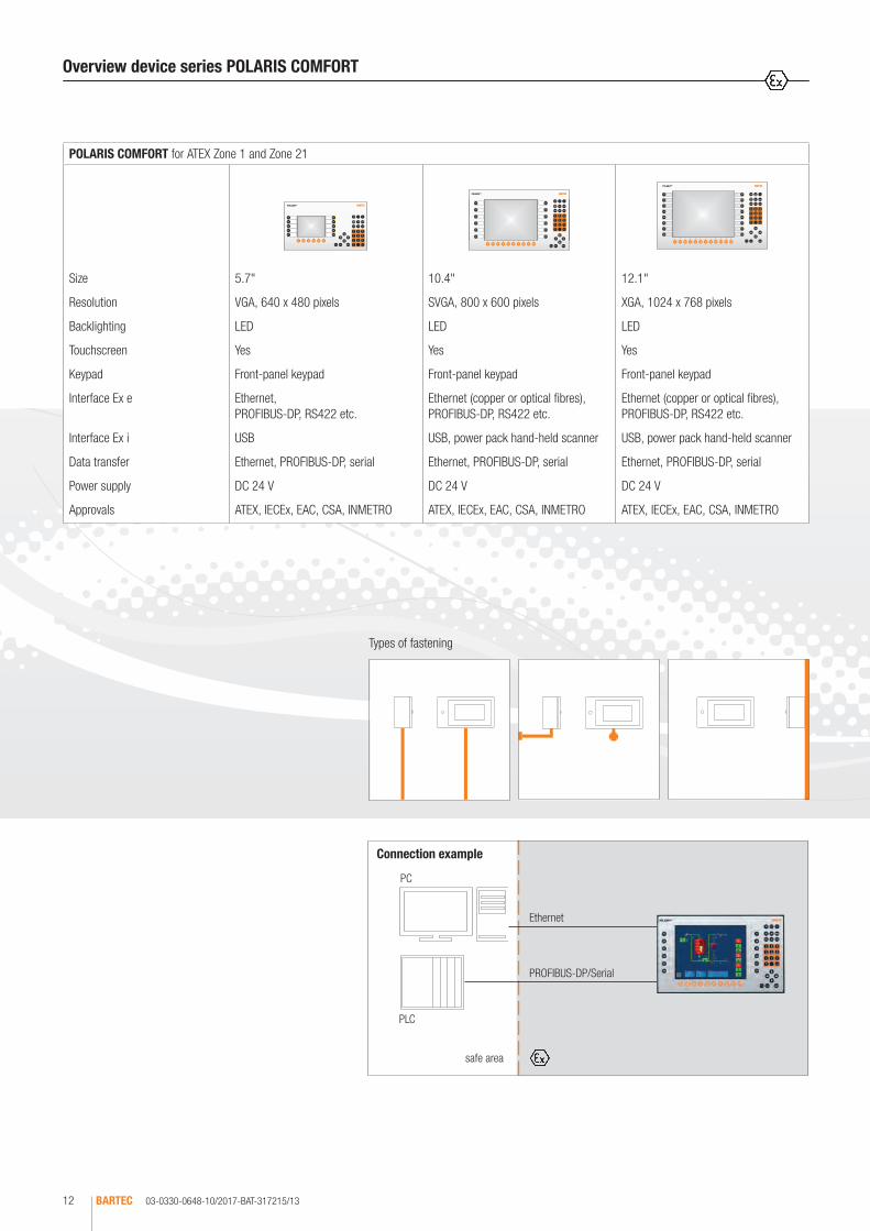
Connection example
safe area
PROFIBUS-DP/Serial
Ethernet
PLC
PC
Types of fastening
Overview device series POLARIS COMFORT
POLARIS COMFORT for ATEX Zone 1 and Zone 21
Size 5.7" 10.4" 12.1"
Resolution VGA, 640 x 480 pixels SVGA, 800 x 600 pixels XGA, 1024 x 768 pixels
Backlighting LED LED LED
Touchscreen Yes Yes Yes
Keypad Front-panel keypad Front-panel keypad Front-panel keypad
Interface Ex e Ethernet, PROFIBUS-DP, RS422 etc.
Ethernet (copper or optical fibres), PROFIBUS-DP, RS422 etc.
Ethernet (copper or optical fibres), PROFIBUS-DP, RS422 etc.
Interface Ex i USB USB, power pack hand-held scanner USB, power pack hand-held scanner
Data transfer Ethernet, PROFIBUS-DP, serial Ethernet, PROFIBUS-DP, serial Ethernet, PROFIBUS-DP, serial
Power supply DC 24 V DC 24 V DC 24 V
Approvals ATEX, IECEx, EAC, CSA, INMETRO ATEX, IECEx, EAC, CSA, INMETRO ATEX, IECEx, EAC, CSA, INMETRO

03-0330-0648-10/2017-BAT-317215/14 BARTEC 13
1
Connection example
safe area
PROFIBUS-DP/Serial/MPI
PLC
Types of fastening
Overview device series POLARIS BASIC
POLARIS BASIC for ATEX Zone 1 and Zone 21
Size Control 5.7" 10.4" 12.1"
Resolution 240 x 64 pixels QVGA, 320 x 240 pixels VGA, 640 x 480 pixels SVGA, 800 x 600 pixels
Backlighting LED CFL CFL CFL
Keypad Front-panel keypad Front-panel keypad Front-panel keypad Front-panel keypad
Interface Ex e RS422/485, PROFIBUS-DP, RS232, TTY
RS422/485, PROFIBUS-DP, RS232, TTY
RS422/485, PROFIBUS-DP, RS232, TTY
RS422/485, PROFIBUS-DP, RS232, TTY
Interface Ex i USB USB USB, power pack hand-held scanner
USB, power pack hand-held scanner
Data transfer PROFIBUS-DP serial: MPI, Modbus etc.
PROFIBUS-DP serial: MPI, Modbus etc.
PROFIBUS-DP serial: MPI, Modbus etc.
PROFIBUS-DP serial: MPI, Modbus etc.
Power supply DC 24 V DC 24 V DC 24 V DC 24 V
Approvals ATEX, IECEx, EAC, CSA, INMETRO
ATEX, IECEx, EAC, CSA, INMETRO
ATEX, IECEx, EAC, CSA, INMETRO
ATEX, IECEx, EAC, CSA, INMETRO

03-0330-0891-10/2017-BAT-406373/1BARTEC14
The POLARIS SMART HMI 7" W is an innovative further development of the PO-LARIS series. The high-resolution display with LED backlighting and touchscreen allows intuitive and comfortable operation. It is optionally available in a capacitive or in a resistive version. The state-of-the-art LED display technology offers optimum contrast even with large viewing angles or in poor lighting conditions. As standard, the Panel PC is equipped with a third-generation processor, the Intel® AtomTM with 2 x 1.46 GHz. The open Windows operating system makes the device series unique on the market. It is also possible to work with the BMS-Graf-Pro. Connection to the control or to the process control system is facilitated by Ethernet. The front-panel insertion allows easy installation. On request, the devices are also available as ready-made system solutions in stainless-steel enclosures for wall or floor mounting. The intrinsically safe USB interfaces are accessible on the back. Intrinsically safe input devices are connected also.
POLARIS SMART HMI 7" W
Technical data
Construction Front-panel fitting
Protection class front/rear: IP 65 acc. to EN/IEC 60529 front: IP 6X acc. to EN/IEC 60079-0 rear: IP 54 acc. to EN/IEC 60079-0
Display 7" W TFT colour display 262,144 colours WVGA resolution, 800 x 480 pixels brightness 500 cd/m2
visible surface approx. 152 mm x 91 mm contrast 600:1 sunlight readable display
Background lighting LED technology service life approx. 50,000 hours (at +25 °C)
Touch capacitive, low-reflection due to optical bonding resistive touch display (membrane touch) on request
Explosion protection
Marking ATEX Zone 1 and 21
II 2G Ex eb q [ib] IIC T4 Gb II 2D Ex tb IIIC T120 °C Db
Certification IBExU 05 ATEX 1117 X
Marking IECEx Ex db eb q [ib] IIC T4 Gb Ex tb IIIC T120 °C Db
Certification IECEx IBE 11.0007X
Other approvals and certificates, see www.bartec.de
Processor CPU Intel® AtomTM (E 3826) Dual Core with 2 x 1.46 GHz RAM: 2 GB (optional: 4 GB) 4 GB internal Flash Drive hard-drive SSD with 128 GB (MLC)
Operating system Windows® 10 IoT or Windows 7® Ultimate or Windows 7® Embedded
Interfaces 2 x Ex i USB 2.0 2 x Ex e USB 2.0 1 x Ethernet 100 BaseT
Dimensions (W x H x D) 240 mm x 170 mm x 80 mm
Wall cut-out 226 mm x 153 mm
Mounting position any
Weight approx. 4,8 kg
Power supply DC 24 V (DC 20 to 30 V)
Supply External supply: DC 24 V/2 A Standard operation without USB: approx. 450 mA
Power dissipation Pmax. (with USB) < 25 W Pmax. (without USB) < 20 W Standard operation without USB: approx. 12.5 W
Permissible ambient temperature
Temperature range
Operation 0 °C to +50 °C Storage -20 °C to +60 °C
extended -20 °C to +60 °C
Relative air humidity 5 % to 95 % non-condensing
Material Front resistive: polyester foil on anodised aluminium plate (conditionally UV-resistant)front capacitive: hardened glass front on anodised aluminium plateback: stainless steel

03-0330-0891-10/2017-BAT-406373/2 BARTEC 15
1
POLARIS SMART HMI 7" W
Safe areaConnection example
PLC
Ethernet
DC 24 V
e. g. connection to the control system, PLC
POLARIS SMART HMI 7" W
Complete order no. 17-71V6-1 /0 00 Please insert correct code. Technical data subject to change without notice. You will find the accessories with order details on the accessories pages.
Ordering information
Description Code no. Version Code no. Operating system Code no.
POLARIS SMART HMI 7" W with capacitive touchscreen
1 2 GB RAM 00Windows® 10 IoT 1
Windows 7® Ultimate 2
POLARIS SMART HMI 7" W with resistive touchscreen
2 4 GB RAM, extended temperature range
11Windows 7® Embedded MUI 3
BMS-Graf-pro 4

03-0330-0707/A-10/2017-BAT-344828/1BARTEC16
High-resolution displays with LED technology and touchscreen for intuitive as well as comfortable operation are available now in the standard variant. State-of-the-art LED display technology ensures the optimum contrast even with a large viewing angle. The panel PC has been equipped as standard with the Dual Core Processor AMD T40E/2 x 1.0 GHz; 4 GB RAM. Windows 7® Ultimate or Windows 7® Embedded MUI can be used as an operating system. Thanks to the integrated keyboard customisation for Windows®, Siemens WinCC flexible®, RS View® or BMS-Graf-pro, the POLARIS Touch panels can be used for all visualisation tasks. They can be connected to the control or the process control system through Ethernet, PROFIBUS-DP or various serial COM interfaces. Of course, here too the user can work with the latest BMS-Graf-Pro Version 7, allowing for example the transfer of projects through Ethernet, the use of graphics lists and the integrated user administration. Wired electrical connections are facilitated by integrated terminal compartments. The front-panel fitting design ensures easy installation. On request, the devices are also available as ready-made system solutions in Stainless-steel enclosures for wall or floor mounting. They also feature an intrinsically safe USB interface for a USB Ex i flash drive. Intrinsically safe input devices can also be connected.
Technical data
Construction Front-panel fitting
Protection class IP 65 (front) IP 54 (back)
Display 10.4" TFT graphic display 262,144 colours Resolution SVGA 800 x 600 pixels Brightness 400 cd/m² Visible surface approx. 211 x 158 mm Contrast 700:1 Touchscreen (resistive)
Backlighting LED technology Service life approx. 50,000 hours (at +25 °C)
Computer capacity Processor AMD T40E/2 x 1.0 GHz 4 GB RAM/100 GB HD optional: 128 GB SSD
Operating system Windows 7® Ultimate or Windows 7® Embedded MUI
Keyboard (short-stroke keys)
Alphanumeric key block 04 cursor keys 10 special keys 12 function keys able to be labelled with LEDs
Interfaces (basic version)
1 x Ex e Ethernet 100/10BaseT 1 x Ex e RS422 1 x Ex i USB for Ex i memory stick 1 x Ex i PS/2 for intrinsically safe mouse
Optional accessories Hand-held scanner on request
Dimensions (W x H x D) 400 mm x 246 mm x approx. 130 mm
Wall cut-out 386 mm x 226 mm + 0.5 mm
Weight approx. 14 kg
Power supply DC 24 V ± 10 %
Max. power consumption Pmax.< 30 W
Permissible ambient temperatures
Storage -20 °C to +50 °C Operation 0 °C to +50 °C
Variant Operation -20 °C to +50 °C on request (without external heating)
Relative air humidity 5 % to 95 % non-condensing
Vibration 0.7 g/1 mm; 5 Hz to 500 Hz pulse in all 3 axes
Shock 15 g/11 ms pulse in all 3 axes
Material Front: polyester foil on anodised aluminium plate (conditionally UV-resistant) Back: bichromated sheet steel
Explosion protection
Marking ATEX Zone 1 and 21
II 2G Ex db eb q [ib] IIC T4 Gb II 2D Ex tb IIIC T120 °C Db
Certification IBExU 05 ATEX 1117 X
Marking IECEx Ex db eb q [ib] IIC T4 Gb Ex tb IIIC T120 °C Db
Certification IECEx IBE 11.0007 X
Other approvals and certificates, see www.bartec.de
Ambient temperature -20 °C to +60 °C
Variant for Zone 2 www.bartec.de
POLARIS PROFESSIONAL POLARIS Panel PC 10.4"

03-0330-0707/A-10/2017-BAT-344828/2 BARTEC 17
1
Safe areaConnection example
PLC
Mouse
Panel PC 10.4"Power supply
e. g. RS422 or PROFIBUS-DP
e. g. connection to the control system, HTML server or remote server
Ethernet
POLARIS PROFESSIONAL POLARIS Panel PC 10.4“
Hand-held scanner BCS 3678ex
Complete order no. 17-71V1-90 / 0000 00 Please insert correct code. Technical data subject to change without notice. You will find the accessoires with order details on the accessories pages.
Ordering information
Description Interfaces Code no. Operating system Code no. Computer capacity Code no.
POLARIS Panel PC 10.4"
USB Ex e/RS422 (recommended version) 37Windows 7®
UltimateU 100 GB HD 0RS485 38
BARTEC PROFIBUS-DP 02
RS232 09
Windows 7®
Embedded MUIF 128 GB SSD 2
TTY 11
BARTEC PROFIBUS-DP, Ex d-USB 33
Further Interface combinations on request XX
Ex e USB

03-0330-0708/A-10/2017-BAT-344829/1BARTEC18
The POLARIS Panel PC 12.1" is an innovative further development of the POLARIS PROFESSIONAL Serie. High-resolution displays with LED technology and touchscreen for intuitive as well as comfortable operation are available now in the standard variant. State-of-the-art LED display technology ensures the optimum contrast even with a large viewing angle. The panel PC has been equipped as standard with the Dual Core Processor AMD T40E/2 x 1.0 GHz; 4 GB RAM. Windows 7® Ultimate or Windows 7® Embedded MUI can be used as an operating system. Thanks to the integrated keyboard customisation for Windows®, Siemens WinCC flexible®, RS View® or BMS-Graf-pro, the POLARIS Touch panels can be used for all visualisation tasks. They can be connected to the control or the process control system through Ethernet, PROFIBUS-DP or various serial COM interfaces. Of course, here too the user can work with the latest BMS-Graf-Pro Version 7, allowing for example the transfer of projects through Ethernet, the use of graphics lists and the integrated user administration. Wired electrical connections are facilitated by integrated terminal compartments. The front-panel fitting design ensures easy installation. On request, the devices are also available as ready-made system solutions in Stainless-steel enclosure for wall or floor mounting. They also feature an intrinsically safe USB interface for a USB Ex i flash drive. Intrinsically safe input devices can also be connected.
Technical data
Construction Front-panel fitting
Protection class IP 65 (front) IP 54 (back)
Display 12.1" TFT graphic display 262,144 colours Resolution XGA 1024 x 768 pixels Brightness 500 cd/m²Visible surface approx. 246 x 184 mm Contrast 700:1 Touchscreen (resistive)
Backlighting LED technology Service life approx. 50,000 hours (at +25 °C)
Computer capacity Processor AMD T40E/2 x 1.0 GHz 4 GB RAM/100 GB HD optional: 128 GB SSD
Operating system Windows 7® Ultimate or Windows 7® Embedded MUI
Keyboard (short-stroke keys)
Alphanumeric key block 04 cursor keys 12 special keys 16 function keys able to be labelled with LEDs
Interfaces (basic version)
1 x Ex e Ethernet 100/10BaseT 1 x Ex e RS422 1 x Ex i USB for Ex i memory stick 1 x Ex i PS/2 for intrinsically safe mouse
Optional accessories Hand-held scanner on request
Dimensions (W x H x D) 440 mm x 275 mm x approx. 130 mm
Wall cut-out 425 mm x 255 mm + 0.5 mm
Gewicht approx. 18 kg
Power supply DC 24 V ± 10 %
Max. power consumption Pmax.< 35 W
Permissible ambient temperatures
Storage -20 °C to +50 °C Operation 0 °C to +50 °C
Variant Operation -20 °C to +50 °C on request (without external heating)
Relative air humidity 5 % to 95 % non-condensing
Vibration 0.7 g/1 mm; 5 Hz to 500 Hz pulse in all 3 axes
Shock 15 g/11 ms pulse in all 3 axes
Material Front: polyester foil on anodised aluminium plate (conditionally UV-resistant) Back: bichromated sheet steel
Explosion protection
Marking ATEX Zone 1 and 21
II 2G Ex db eb q [ib] IIC T4 Gb II 2D Ex tb IIIC T120 °C Db
Certification IBExU 05 ATEX 1117 X
Marking IECEx Ex db eb q [ib] IIC T4 Gb Ex tb IIIC T120 °C Db
Certification IECEx IBE 11.0007 X
Other approvals and certificates, see www.bartec.de
Ambient temperature -20 °C to +60 °C
Variant for Zone 2 www.bartec.de
POLARIS PROFESSIONAL POLARIS Panel PC 12.1"

03-0330-0708/A-10/2017-BAT-344829/2 BARTEC 19
1
Safe areaConnection example
PLC
Mouse
Panel PC 12.1"
Power supply
e. g. RS422 or PROFIBUS-DP
e. g. connection to the control system, HTML server or remote server
Ethernet
POLARIS PROFESSIONAL POLARIS Panel PC 12.1"
Hand-held scanner BCS 3678ex
Complete order no. 17-71V1-80 / 0000 00 Please insert correct code. Technical data subject to change without notice. You will find the accessoires with order details on the accessories pages.
Ordering information
Description Interfaces Code no. Operating system Code no. Computer capacity Code no.
POLARIS Panel PC 12.1"
USB Ex e/RS422 (recommended version) 37Windows 7®
UltimateU 100 GB HD 0RS485 38
BARTEC PROFIBUS-DP 02
RS232 09
Windows 7®
Embedded MUIF 128 GB SSD 2
TTY 11
BARTEC PROFIBUS-DP, Ex d-USB 33
Further Interface combinations on request XX
Ex e USB
03-0330-0709-10/2017-BAT-344835/1BARTEC20
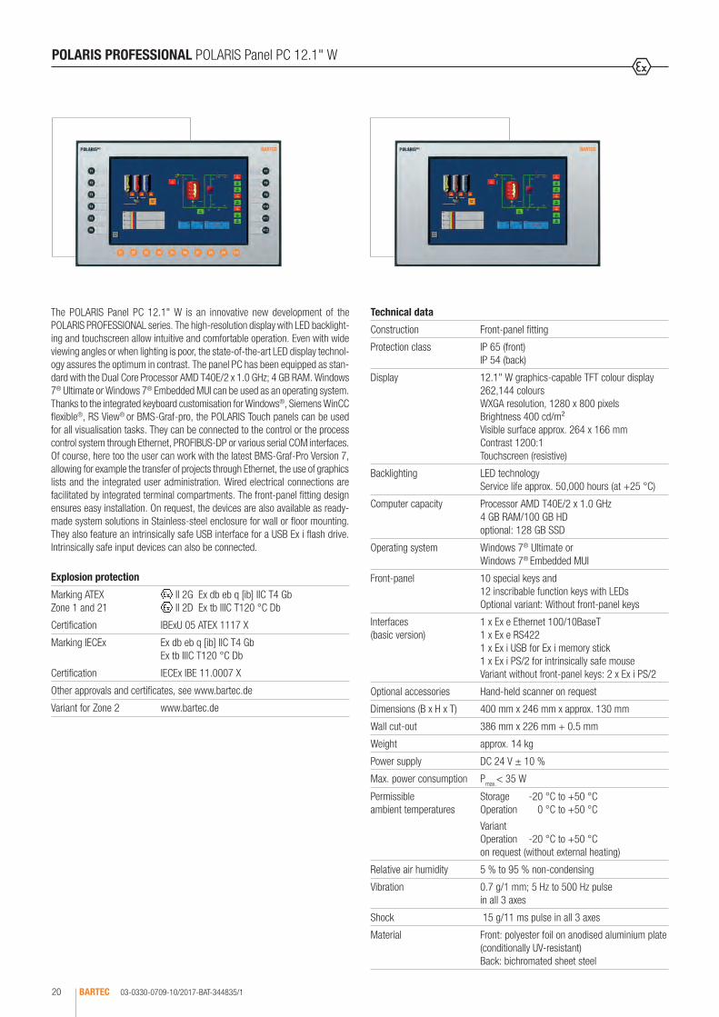
The POLARIS Panel PC 12.1" W is an innovative new development of the POLARIS PROFESSIONAL series. The high-resolution display with LED backlight-ing and touchscreen allow intuitive and comfortable operation. Even with wide viewing angles or when lighting is poor, the state-of-the-art LED display technol-ogy assures the optimum in contrast. The panel PC has been equipped as stan-dard with the Dual Core Processor AMD T40E/2 x 1.0 GHz; 4 GB RAM. Windows 7® Ultimate or Windows 7® Embedded MUI can be used as an operating system.Thanks to the integrated keyboard customisation for Windows®, Siemens WinCC flexible®, RS View® or BMS-Graf-pro, the POLARIS Touch panels can be used for all visualisation tasks. They can be connected to the control or the process control system through Ethernet, PROFIBUS-DP or various serial COM interfaces. Of course, here too the user can work with the latest BMS-Graf-Pro Version 7, allowing for example the transfer of projects through Ethernet, the use of graphics lists and the integrated user administration. Wired electrical connections are facilitated by integrated terminal compartments. The front-panel fitting design ensures easy installation. On request, the devices are also available as ready-made system solutions in Stainless-steel enclosure for wall or floor mounting. They also feature an intrinsically safe USB interface for a USB Ex i flash drive. Intrinsically safe input devices can also be connected.
Technical data
Construction Front-panel fitting
Protection class IP 65 (front) IP 54 (back)
Display 12.1" W graphics-capable TFT colour display 262,144 colours WXGA resolution, 1280 x 800 pixels Brightness 400 cd/m² Visible surface approx. 264 x 166 mm Contrast 1200:1 Touchscreen (resistive)
Backlighting LED technology Service life approx. 50,000 hours (at +25 °C)
Computer capacity Processor AMD T40E/2 x 1.0 GHz 4 GB RAM/100 GB HD optional: 128 GB SSD
Operating system Windows 7® Ultimate or Windows 7® Embedded MUI
Front-panel 10 special keys and 12 inscribable function keys with LEDs Optional variant: Without front-panel keys
Interfaces (basic version)
1 x Ex e Ethernet 100/10BaseT 1 x Ex e RS422 1 x Ex i USB for Ex i memory stick 1 x Ex i PS/2 for intrinsically safe mouse Variant without front-panel keys: 2 x Ex i PS/2
Optional accessories Hand-held scanner on request
Dimensions (B x H x T) 400 mm x 246 mm x approx. 130 mm
Wall cut-out 386 mm x 226 mm + 0.5 mm
Weight approx. 14 kg
Power supply DC 24 V ± 10 %
Max. power consumption Pmax.< 35 W
Permissible ambient temperatures
Storage -20 °C to +50 °C Operation 0 °C to +50 °C
Variant Operation -20 °C to +50 °C on request (without external heating)
Relative air humidity 5 % to 95 % non-condensing
Vibration 0.7 g/1 mm; 5 Hz to 500 Hz pulse in all 3 axes
Shock 15 g/11 ms pulse in all 3 axes
Material Front: polyester foil on anodised aluminium plate (conditionally UV-resistant) Back: bichromated sheet steel
Explosion protection
Marking ATEX Zone 1 and 21
II 2G Ex db eb q [ib] IIC T4 Gb II 2D Ex tb IIIC T120 °C Db
Certification IBExU 05 ATEX 1117 X
Marking IECEx Ex db eb q [ib] IIC T4 Gb Ex tb IIIC T120 °C Db
Certification IECEx IBE 11.0007 X
Other approvals and certificates, see www.bartec.de
Variant for Zone 2 www.bartec.de
POLARIS PROFESSIONAL POLARIS Panel PC 12.1" W

03-0330-0709-10/2017-BAT-344835/2 BARTEC 21
1
Safe areaConnection example
PLC
Mouse
Panel PC 12.1" W
Hand-held scanner BCS 3678ex
DC 24 V
e. g. RS422 or PROFIBUS-DP
e. g. connection to the control system, HTML server or remote server
Ethernet
POLARIS PROFESSIONAL POLARIS Panel PC 12.1" W
Complete order no. 17-71V1-B / 0000 00 Please insert correct code. Technical data subject to change without notice. You will find the accessories with order details on the accessories pages.
Ordering information
Description Code no. Interfaces Code no. Operating system Code no. Computer capacity Code no.
Panel PC 12.1" W with front-panel keys
0
USB Ex e/RS422 (recommended version) 37Windows 7®
UltimateU 100 GB HD 0RS485 38
BARTEC PROFIBUS-DP 02
RS232 09
Panel PC 12.1" W without front-panel keys
4 Windows 7®
Embedded MUIF 128 GB SSD 2
TTY 11
BARTEC PROFIBUS-DP, Ex d-USB 33
Further Interface combinations on request XX
Ex e USB

03-0330-0402-10/2017-BAT-236274/1BARTEC22
The panel PC has been equipped as standard with the Dual Core Processor AMD T40E/2 x 1.0 GHz; 4 GB RAM. The Ethernet interface can be used to connect individual computers or network devices, e. g. a printer, to an existing local network (LAN) (WLAN is also a possible option) or local networks can be set up completely wirelessly. This facilitates a high-performance visualisation and operation of the processes directly on site. The wired electrical connections are realised via a terminal compartment of the “e” type of protection (increased safety). The state-of-the-art display technology guarantees an optimum contrast, even with large viewing angle. The Front-panel fitting assures easy installation. On request, the devices are also available as ready-made system solutions in Stainless-steel enclosure for wall or floor mounting. An intrinsically safe USB interface is available for a USB Ex i memory stick. Intrinsically safe input devices can also be connected. The optional (intrinsically safe) touchscreen offers the optimum in operating comfort. Windows 7® Ultimate or Windows 7® Embedded MUI can be used as an operating system. The Panel PCs therefore support the installation of numerous software packages, such as customer-specific software or other commercially available standard visualisation software. Of course, here too the operator can also work with the BARTEC “BMS-Graf-pro“ programming package (Version 7.xxx or newer). The BARTEC PROFIBUS-DP interface can only be used in connection with the BARTEC “BMS-Graf- pro” software.
POLARIS PROFESSIONAL POLARIS Panel PC 15"
Technical data
Construction Front-panel fitting
Protection class IP 65 (front) IP 54 (back)
Display 15” graphics-capable TFT colour display 16.7 million colours XGA resolution, 1024 x 768 pixels Brightness 350 cd/m2
Visible area approx. 304 x 228 mm Contrast 700:1 Antireflection-coating glass pane Optional touchscreen (resistive)
Backlighting LED technology Service life approx. 50,000 hours (at +25 °C)
Computer capacity Processor AMD T40E/2 x 1.0 GHz 4 GB RAM/100 GB HD optional: 128 GB SSD
Operating system Windows 7® Ultimate or Windows 7® Embedded MUI
Interfaces (Basic version)
1 x Ex e Ethernet 100/10BaseT (option of optical fibres) 1 x Ex e RS422 1 x Ex i USB for Ex i memory stick 2 x Ex i PS/2 for intrinsically safe mouse
Optional accessories Hand-held scanner on request
Dimensions (W x H x D) 411 mm x 332 mm x approx. 135 mm
Wall cut-out 394.5 mm x 315.5 mm + 0.5 mm
Weight approx. 23 kg
Power supply AC 90 to 253 V, 50 to 60 Hz DC 24 V ± 10 % on request
Max. power consumption Pmax. < 70 W
Admissible ambient temperature
Storage -20 °C to +50 °C Operation 0 °C to +50 °C System solution with heating on request.
Relative air humidity 5 to 95 % non-condensing
Vibration 0.7 g/1 mm; 5 Hz to 500 Hz pulse in all 3 axes
Shock 15 g/11 ms pulse in all 3 axes
Material Front: polyester foil on anodised aluminium plate (conditionally UV-resistant) Back: bichromated sheet steel
Explosion protection
Marking ATEX Zone 1 and 21
II 2G Ex db eb q [ib] IIC T4 Gb II 2D Ex tb IIIC T120 °C Db
Certification IBExU 05 ATEX 1117 X
Marking IECEx Ex db eb q [ib] IIC T4 Gb Ex tb IIIC T120 °C Db
Certification IECEx IBE 11.0007 X
Other approvals and certificates, see www.bartec.de
Ambient temperature -20 °C to +60 °C
Variant for Zone 2 www.bartec.de

03-0330-0402-10/2017-BAT-236274/2 BARTEC 23
1
BestellangabenOrdering informationLes informations de commandeДанные для заказаDatos del pedidoDados para encomendaSipariş bilgileri
Connection exampleSafe area
PLC
Keyboard Mouse
Power supply
Ethernet
e. g. RS422 or PROFIBUS-DP
Panel PC 15"
POLARIS PROFESSIONAL POLARIS Panel PC 15"
Hand-held scanner BCS 3678ex
Complete order no. 17-71V1- 0 / 000 00 Please insert correct code. Technical data subject to change without notice. You will find the accessories with order details on the accessories pages.
Ordering information
Description Code no.
Interfaces Code no.
Operating system
Code no.
Variant Code no.
Computer capacity
Code no.
Panel PC 15" without touchscreen
4
USB Ex e/RS422 (recommended version) 76Windows 7®
UltimateU AC 0 100 GB HD 0RS485 83
BARTEC PROFIBUS-DP 02
RS232 09
Panel PC 15" with touchscreen
6 Windows 7®
Embedded MUIF DC 2 128 GB SSD 2
TTY 11
BARTEC PROFIBUS-DP, Ex d-USB 33
Further Interface combinations on request XX
Ex e USB

Der Panel-PC ist serienmäßig mit dem Dual-Core-Prozessor AMD T40E/2 x 1,0 GHz; 4 GB RAM ausgerüstet. Als mögliche Betriebssysteme stehen Windows 7® Ultimate oder Windows 7® Embedded MUI zur Verfügung.
The panel PC has been equipped as standard with the Dual Core Processor AMD T40E/2 x 1.0 GHz; 4 GB RAM. Windows 7® Ultimate or Windows 7® Embedded MUI can be used as an operating system.
03-0330-0651-10/2017-BAT-318609/1BARTEC24
The POLARIS Panel PC 15" Sunlight is enhanced with industrial LED backlight-ing, which reaches a very high brightness of 1,000 cd/m2. Combined with the special characteristics of the front polarizer, this allows excellent readability even under strong sunlight and it is therefore ideal for use outdoors. The panel PC has been equipped as standard with the Dual Core Processor AMD T40E/ 2 x 1.0 GHz; 4 GB RAM. The Ethernet interface can be used to connect individual computers or network devices, e. g. a printer, to an existing local network (LAN) (WLAN is also a possible option) or local networks can be set up completely wirelessly. This facilitates a high-performance visualisation and operation of the processes directly on site. The wired electrical connections are realised via a terminal compartment of the “e” type of protection (increased safety). The state-of-the-art display technology guarantees an optimum contrast, even with large viewing angle. The Front-panel fitting assures easy installation. On request, the devices are also available as ready-made system solutions in Stainless-steel enclosure for wall or floor mounting. An intrinsically safe USB interface is available for a USB Ex i memory stick.Intrinsically safe input devices can also be connected. The optional (intrinsically safe) touchscreen offers the optimum in operating comfort. Windows 7® Ultimate or Windows 7® Embedded MUI can be used as an operating system. The Panel PCs therefore support the installation of numerous software packages, such as customer-specific software or other commercially available standard visualisation software. Of course, here too the operator can also work with the BARTEC “BMS-Graf-pro” programming package (Version 7.xxx or newer). The BARTEC PROFIBUS-DP interface can only be used in connection with the BARTEC “BMS-Graf-pro” software.
POLARIS PROFESSIONAL POLARIS Panel PC 15" Sunlight
Technical data
Construction Front-panel fitting
Protection class IP 65 (front) IP 54 (back)
Display 15" graphics-capable TFT colour display 262,144 colours XGA resolution, 1024 x 768 pixels Brightness up to 1000 cd/m2 Visible area approx. 304 x 228 mm Contrast 700:1 Antireflection-coating glass pane Optional touchscreen (resistive)
Backlighting CFL technology Service life approx. 50,000 hours (at +25 °C)
Computer capacity Processor AMD T40E/2 x 1.0 GHz 4 GB RAM/100 GB HD optional: 128 GB SSD
Operating system Windows 7® Ultimate or Windows 7® Embedded MUI
Interfaces (Basic version)
1 x Ex e Ethernet 100/10BaseT (option of optical fibres) 1 x Ex e RS422 1 x Ex i USB for Ex i memory stick 2 x Ex i PS/2 for intrinsically safe keyboard and mouse
Optional accessories Hand-held scanner on request
Dimensions (W x H x D) 411 mm x 332 mm x approx. 135 mm
Wall cut-out 394.5 mm x 315.5 mm + 0.5 mm
Gewicht approx. 23 kg
Power supply AC 90 to 253 V, 50 to 60 Hz DC 24 V ± 10 %
Max. power consumption Pmax. < 70 W
Admissible ambient temperature
Storage -20 °C to +60 °C Operation 0 °C to +60 °C
Relative air humidity 5 to 95 % non-condensing
Vibration 0.7 g/1 mm; 5 Hz to 500 Hz pulse in all 3 axes
Shock 15 g/11 ms pulse in all 3 axes
Material Front: polyester foil on anodised aluminium plate (conditionally UV-resistant) Back: bichromated sheet steel
Explosion protection
Marking ATEX Zone 1 and 21
II 2G Ex db eb q [ib] IIC T4 Gb II 2D Ex tb IIIC T120 °C Db
Certification IBExU 05 ATEX 1117 X
Marking IECEx Ex db eb q [ib] IIC T4 Gb Ex tb IIIC T120 °C Db
Certification IECEx IBE 11.0007 X
Other approvals and certificates, see www.bartec.de
Variant for Zone 2 www.bartec.de

03-0330-0651-10/2017-BAT-318609/2 BARTEC 25
1
Safe areaConnection example
PLC
Keyboard Mouse
Panel PC 15" SunlightPower supply
Ethernet
e. g. RS422 or PROFIBUS-DP
POLARIS PROFESSIONAL POLARIS Panel PC 15" Sunlight
Complete order no. 17-71V1- 2 / 000 00 Please insert correct code. Technical data subject to change without notice. You will find the accessories with order details on the accessories pages.
Ordering information
Description Code no.
Interfaces Code no.
Operating system
Code no.
Variant Code no.
Computer capacity
Code no.
Panel PC 15" Sunlight without touchscreen
4
USB Ex e/RS422 (recommended version) 76Windows 7®
UltimateU AC 0 100 GB HD 0RS485 83
BARTEC PROFIBUS-DP 02
RS232 09
Panel PC 15" Sunlight with touchscreen
6 Windows 7®
Embedded MUIF DC 2 128 GB SSD 2
TTY 11
BARTEC PROFIBUS-DP, Ex d-USB 33
Further Interface combinations on request XX
Hand-held scanner BCS 3678ex
Ex e USB

03-0330-0784-10/2017-BAT-364905/1BARTEC26
The panel PC has been equipped as standard with the Dual Core Processor AMD T40E/2 x 1.0 GHz; 4 GB RAM. The Ethernet interface can be used to connect individual computers or network devices, e. g. a printer, to an existing local network (LAN) (WLAN is also a possible option) or local networks can be set up completely wirelessly. This facilitates a high-performance visualisation and operation of the processes directly on site. The wired electrical connections are realised via a terminal compartment of the “e” type of protection (increased safety). The state-of-the-art display technology guarantees an optimum contrast, even with large viewing angle. The Front-panel fitting assures easy installation. On request, the devices are also available as ready-made system solutions in Stainless-steel enclosure for wall or floor mounting. An intrinsically safe USB interface is available for a USB Ex i memory stick. Intrinsically safe input devices can also be connected. The optional (intrinsically safe) touchscreen offers the optimum in operating comfort. Windows 7® Ultimate or Windows 7® Embedded MUI can be used as an operating system. The Panel PCs therefore support the installation of numerous software packages, such as customer-specific software or other commercially available standard visualisation software. Of course, here too the operator can also work with the BARTEC “BMS-Graf-pro” programming package (Version 7.xxx or newer). The BARTEC PROFIBUS-DP interface can only be used in connection with the BARTEC “BMS-Graf-pro” software.
POLARIS PROFESSIONAL POLARIS Panel PC 17.3" W
Technical data
Construction Front-panel fitting
Protection class IP 65 (front) IP 54 (back)
Display 17.3" W graphics-capable TFT colour display 16.7 million colours Full HD resolution, 1920 x 1080 pixels Brightness 400 cd/m2
Visible area approx. 382 x 215 mm Contrast 600:1 Antireflection-coating glass pane Optional touchscreen (resistive)
Backlighting LED technology
Computer capacity Processor AMD T40E/2 x 1.0 GHz 4 GB RAM/100 GB HD optional: 128 GB SSD
Operating system Windows 7® Ultimate or Windows 7® Embedded MUI
Interfaces (Basic version)
1 x Ex e Ethernet 100/10BaseT (option of optical fibres) 1 x Ex e RS422 1 x Ex i USB for Ex i memory stick 2 x Ex i PS/2 for intrinsically safe keyboard and mouse
Optional accessories Hand-held scanner on request
Dimensions (W x H x D) 503 mm x 314 mm x approx. 135 mm
Wall cut-out 489 mm x 300 mm + 0.5 mm
Weight approx. 33 kg
Power supply AC 90 to 253 V, 50 to 60 Hz DC 24 V ± 10 % on request
Max. power consumption Pmax. < 100 W depending on the variant
Admissible ambient temperature
Storage -20 °C to +50 °C Operation 0 °C to +50 °C System solution with heating on request.
Relative air humidity 5 to 95 % non-condensing
Vibration 0.7 g/1 mm; 5 Hz to 500 Hz pulse in all 3 axes
Shock 15 g/11 ms pulse in all 3 axes
Material Front: polyester foil on anodised aluminium plate (conditionally UV-resistant) Back: bichromated sheet steel
Explosion protection
Marking ATEX Zone 1 and 21
II 2G Ex db eb q [ib] IIC T4 Gb II 2D Ex tb IIIC T120 °C Db
Certification IBExU 05 ATEX 1117 X
Marking IECEx Ex db eb q [ib] IIC T4 Gb Ex tb IIIC T120 °C Db
Certification IECEx IBE 11.0007 X
Other approvals and certificates, see www.bartec.de
Variant for Zone 2 www.bartec.de
Der Panel-PC ist serienmäßig mit dem Dual-Core-Prozessor AMD T40E/2 x 1,0 GHz; 4 GB RAM ausgerüstet. Als mögliche Betriebssysteme stehen Windows 7® Ultimate oder Windows 7® Embedded MUI zur Verfügung.
The panel PC has been equipped as standard with the Dual Core Processor AMD T40E/2 x 1.0 GHz; 4 GB RAM. Windows 7® Ultimate or Windows 7® Embedded MUI can be used as an operating system.
03-0330-0784-10/2017-BAT-364905/2 BARTEC 27
1
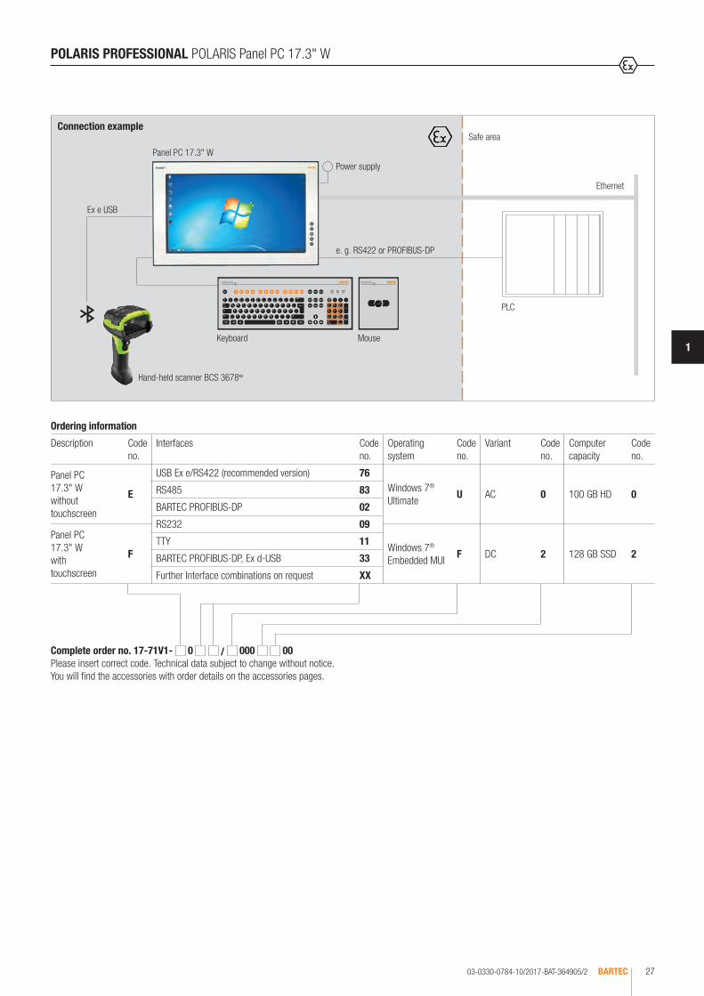
Connection exampleSafe area
PLC
Keyboard Mouse
Power supply
Ethernet
e. g. RS422 or PROFIBUS-DP
Panel PC 17.3" W
POLARIS PROFESSIONAL POLARIS Panel PC 17.3" W
Complete order no. 17-71V1- 0 / 000 00 Please insert correct code. Technical data subject to change without notice. You will find the accessories with order details on the accessories pages.
Ordering information
Description Code no.
Interfaces Code no.
Operating system
Code no.
Variant Code no.
Computer capacity
Code no.
Panel PC 17.3" W without touchscreen
E
USB Ex e/RS422 (recommended version) 76Windows 7®
UltimateU AC 0 100 GB HD 0RS485 83
BARTEC PROFIBUS-DP 02
RS232 09Panel PC 17.3" W with touchscreen
F Windows 7®
Embedded MUIF DC 2 128 GB SSD 2
TTY 11
BARTEC PROFIBUS-DP, Ex d-USB 33
Further Interface combinations on request XX
Hand-held scanner BCS 3678ex
Ex e USB

03-0330-0401-05/2017-BAT-236273/1BARTEC28
The panel PC has been equipped as standard with the Dual Core Processor AMD T40E/2 x 1.0 GHz; 4 GB RAM. The Ethernet interface can be used to connect individual computers or network devices, e. g. a printer, to an existing local network (LAN) (WLAN is also a possible option) or local networks can be set up completely wirelessly. This facilitates a high-performance visualisation and operation of the processes directly on site. The wired electrical connec-tions are realised via a terminal compartment of the “e” type of protection (increased safety). The state-of-the-art display technology guarantees an optimum contrast, even with large viewing angle. The Front-panel fitting assures easy installation. On request, the devices are also available as ready-made system solutions in Stainless-steel enclosure for wall or floor mounting.An intrinsically safe USB interface is available for a USB Ex i memory stick. Intrinsically safe input devices can also be connected. The optional (intrinsi-cally safe) touchscreen offers the optimum in operating comfort. Windows 7® Ultimate or Windows 7® Embedded MUI can be used as an operating system.This means that the PCs are open for many different software packages, for example customised software or various types of commercially available standard visualisation software. Of course, here too the operator can also work with the BARTEC “BMS-Graf-pro” programming package (Version 7.xxx or newer). The BARTEC PROFIBUS-DP interface can only be used in connection with the BARTEC “BMS-Graf-pro” software.
POLARIS PROFESSIONAL POLARIS Panel PC 19.1"
Technical data
Construction Front-panel fitting
Protection class IP 65 (front) IP 54 (back)
Display 19.1" graphics-capable TFT colour display 16.7 million colours SXGA resolution, 1280 x 1024 pixels Brightness 300 cd/m2
Visible area approx. 380 x 305 mm Contrast 1300:1 Antireflection-coating glass pane Optional touchscreen (resistive)
Backlighting CFL technology Service life approx. 40,000 hours (at +25 °C)
Computer capacity Processor AMD T40E/2 x 1.0 GHz 4 GB RAM/100 GB HD optional: 128 GB SSD
Operating system Windows 7® Ultimate or Windows 7® Embedded MUI
Interfaces (Basic version)
1 x Ex e Ethernet 100/10BaseT (option of optical fibres) 1 x Ex e RS422 1 x Ex i USB for Ex i memory stick 2 x Ex i PS/2 for intrinsically safe keyboard and mouse
Optional accessories Hand-held scanner on request
Dimensions (W x H x D) 498 mm x 400 mm x approx. 135 mm
Wall cut-out 484 mm x 386.5 mm + 0.5 mm
Weight approx. 33 kg
Power supply AC 90 to 253 V, 50 to 60 Hz DC 24 V ± 10 % on request
Max. power consumption Pmax. < 70 W
Admissible ambient temperature
Storage -20 °C to +50 °C Operation 0 °C to +50 °C System solution with heating on request.
Relative air humidity 5 to 95 % non-condensing
Vibration 0.7 g/1 mm; 5 Hz to 500 Hz pulse in all 3 axes
Shock 15 g/11 ms pulse in all 3 axes
Material Front: polyester foil on anodised aluminium plate (conditionally UV-resistant) Back: bichromated sheet steel
Explosion protection
Marking ATEX Zone 1 and 21
II 2G Ex db eb q [ib] IIC T4 Gb II 2D Ex tb IIIC T120 °C Db
Certification IBExU 05 ATEX 1117 X
Marking IECEx Ex db eb q [ib] IIC T4 Gb Ex tb IIIC T120 °C Db
Certification IECEx IBE 11.0007 X
Other approvals and certificates, see www.bartec.de
Ambient temperature -20 °C to +60 °C
Variant for Zone 2 www.bartec.de
03-0330-0401-05/2017-BAT-236273/2 BARTEC 29
1
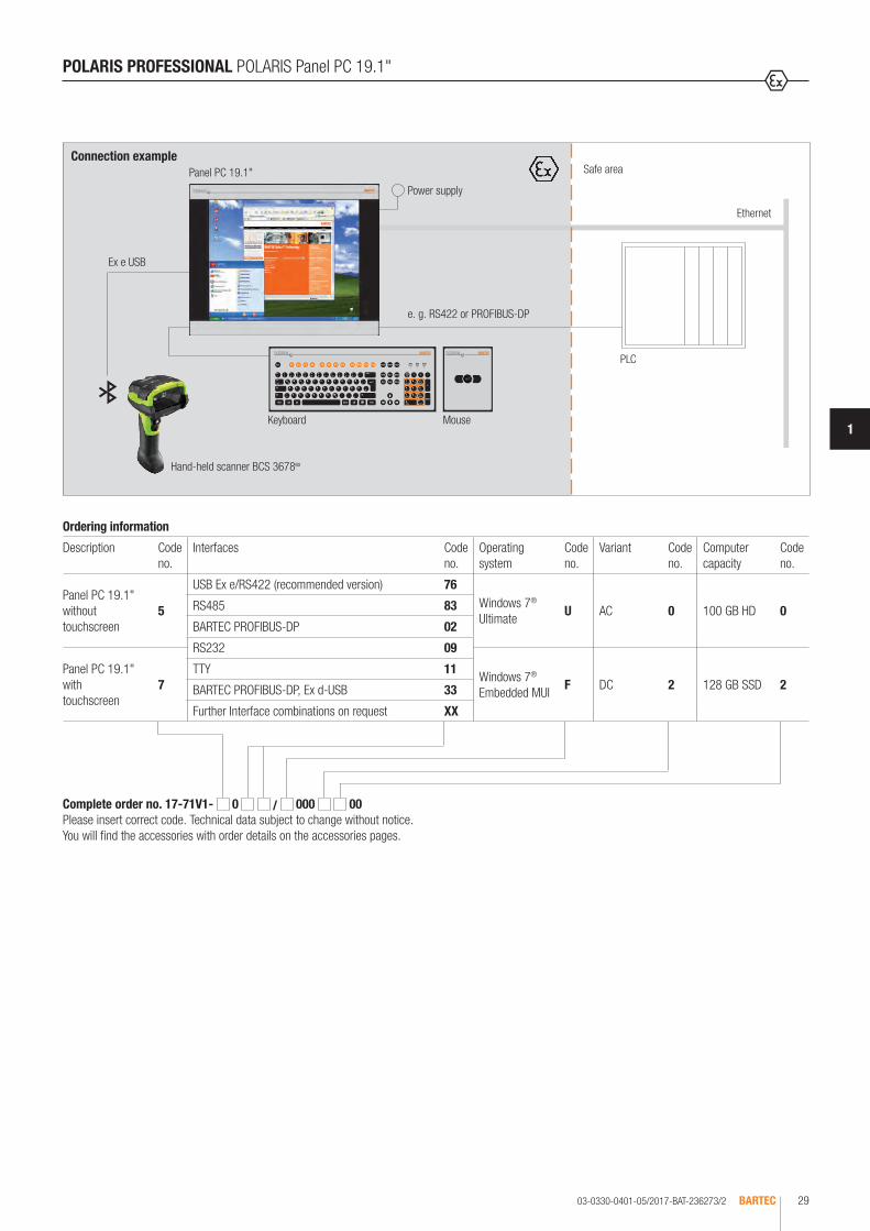
Connection exampleSafe area
PLC
Keyboard Mouse
Power supply
Ethernet
e. g. RS422 or PROFIBUS-DP
Panel PC 19.1"
POLARIS PROFESSIONAL POLARIS Panel PC 19.1"
Hand-held scanner BCS 3678ex
Complete order no. 17-71V1- 0 / 000 00 Please insert correct code. Technical data subject to change without notice. You will find the accessories with order details on the accessories pages.
Ordering information
Description Code no.
Interfaces Code no.
Operating system
Code no.
Variant Code no.
Computer capacity
Code no.
Panel PC 19.1" without touchscreen
5
USB Ex e/RS422 (recommended version) 76Windows 7®
UltimateU AC 0 100 GB HD 0RS485 83
BARTEC PROFIBUS-DP 02
RS232 09
Panel PC 19.1" with touchscreen
7 Windows 7®
Embedded MUIF DC 2 128 GB SSD 2
TTY 11
BARTEC PROFIBUS-DP, Ex d-USB 33
Further Interface combinations on request XX
Ex e USB

03-0330-0687-10/2017-BAT-334208/1BARTEC30
The panel PC has been equipped as standard with the Dual Core Processor AMD T40E/2 x 1.0 GHz; 4 GB RAM. The Ethernet interface can be used to connect individual computers or network devices, e. g. a printer, to an existing local network (LAN) (WLAN is also a possible option) or local networks can be set up completely wirelessly. This facilitates a high-performance visualisation and operation of the processes directly on site. The wired electrical connections are realised via a terminal compartment of the “e” type of protection (increased safety). The state-of-the-art display technology guarantees an optimum contrast, even with large viewing angle. The Front-panel fitting assures easy installation. On request, the devices are also available as ready-made system solutions in Stainless-steel enclosure for wall or floor mounting. An intrinsically safe USB interface is available for a USB Ex i memory stick. Intrinsically safe input devices can also be connected. The optional (intrinsically safe) touchscreen offers the optimum in operating comfort. Windows 7® Ultimate or Windows 7® Embedded MUI can be used as an operating system. The Panel PCs therefore support the installation of numerous software packages, such as customer-specific software or other commercially available standard visualisation software. Of course, here too the operator can also work with the BARTEC “BMS-Graf-pro” programming package (Version 7.xxx or newer). The BARTEC PROFIBUS-DP interface can only be used in connection with the “BMS-Graf-pro” software.
POLARIS PROFESSIONAL POLARIS Panel PC 24" W
Technical data
Construction Front-panel fitting
Protection class IP 65 (front) IP 54 (back)
Display 24" W graphics-capable TFT colour display 16.7 million colours Full HD resolution, 1920 x 1080 pixels Brightness 300 cd/m2
Visible area approx. 531 x 299 mm Contrast 3000:1 Antireflection-coating glass pane Optional touchscreen (resistive)
Backlighting LED technology
Computer capacity Processor AMD T40E/2 x 1.0 GHz 4 GB RAM/100 GB HD optional: 128 GB SSD
Operating system Windows 7® Ultimate or Windows 7® Embedded MUI
Interfaces (Basic version)
1 x Ex e Ethernet 100/10BaseT (option of optical fibres) 1 x Ex e RS422 1 x Ex i USB for Ex i memory stick 2 x Ex i PS/2 for intrinsically safe keyboard and mouse
Optional accessories Hand-held scanner on request
Dimensions (W x H x D) 644 mm x 406 mm x approx. 135 mm
Wall cut-out 630 mm x 392 mm + 0.5 mm
Weight approx. 40 kg
Power supply AC 90 to 253 V, 50 to 60 Hz DC 24 V ± 10 % on request
Max. power consumption Pmax. < 100 W depending on the variant
Admissible ambient temperature
Storage -20 °C to +50 °C Operation 0 °C to +50 °C System solution with heating on request.
Relative air humidity 5 to 95 % non-condensing
Vibration 0.7 g/1 mm; 5 Hz to 500 Hz pulse in all 3 axes
Shock 15 g/11 ms pulse in all 3 axes
Material Front: polyester foil on anodised aluminium plate (conditionally UV-resistant) Back: bichromated sheet steel
Explosion protection
Marking ATEX Zone 1 and 21
II 2G Ex db eb q [ib] IIC T4 Gb II 2D Ex tb IIIC T120 °C Db
Certification IBExU 05 ATEX 1117 X
Marking IECEx Ex db eb q [ib] IIC T4 Gb Ex tb IIIC T120 °C Db
Certification IECEx IBE 11.0007 X
Other approvals and certificates, see www.bartec.de
Variant for Zone 2 www.bartec.de

03-0330-0687-10/2017-BAT-334208/2 BARTEC 31
1
Connection exampleSafe area
PLC
Keyboard Mouse
Power supply
Ethernet
e. g. RS422 or PROFIBUS-DP
Panel PC 24" W
POLARIS PROFESSIONAL POLARIS Panel PC 24" W
Hand-held scanner BCS 3678ex
Complete order no. 17-71V1- 0 / 000 00 Please insert correct code. Technical data subject to change without notice. You will find the accessories with order details on the accessories pages.
Ordering information
Description Code no.
Interfaces Code no.
Operating system
Code no.
Variant Code no.
Computer capacity
Code no.
Panel PC 24" W without touchscreen
C
USB Ex e/RS422 (recommended version) 76Windows 7®
UltimateU AC 0 100 GB HD 0RS485 83
BARTEC PROFIBUS-DP 02
RS232 09Panel PC 24" W with touchscreen
D Windows 7®
Embedded MUIF DC 2 128 GB SSD 2
TTY 11
BARTEC PROFIBUS-DP, Ex d-USB 33
Further Interface combinations on request XX
Ex e USB

03-0330-0649-10/2017-BAT-317216/1BARTEC32
The panel PC has been equipped as standard with the Dual Core Processor AMD T40E/2 x 1.0 GHz; 4 GB RAM. The Ethernet interface enables individual computers or network devices such as a printer to be connected to an exist-ing local network (LAN) (WLAN is also a possible option) or local networks to be set up completely wirelessly. Allows high-performance visual display and operation of the processes directly on site. State-of-the-art display technology provides optimum contrast even with a large viewing angle. To allow the great-est ease in utilisation the devices are available for wall, floor or table mounting. A keyboard with integrated trackball or touchpad can be connected. There is also the option of a touchscreen for the ultimate in operating ease. Windows 7® Ultimate or Windows 7® Embedded MUI can be used as an operating system.This means that the Panel PCs are open for many different software packages, for example customised software or various types of commercially available standard visualisation software.
POLARIS PROFESSIONAL POLARIS II Panel PC 19.1" for ATEX Zone 2 and ATEX Zone 21/22
Technical data
Construction Stainless-steel enclosure
Protection class IP 65
Display 19.1" graphics-capable TFT colour display 16.7 million colours SXGA resolution, 1280 x of 1024 pixels Brightness 300 cd/m² Visible surface approx. 376 x 301 mm Contrast 1300:1 Optional touchscreen (resistive)
Backlighting CFL technology Service life approx. 50,000 hours (at +25 °C)
Computer capacity Processor AMD T40E/2 x 1.0 GHz 4 GB RAM/128 GB SSD
Operating system Windows 7® Ultimate or Windows 7® Embedded MUI
Interfaces (basic version)
2 x Ethernet 100BaseT 2 x PS/2 for keyboard and mouse 2 x RS232 Sub D (2 x RS232 optional) 4 x USB
Dimensions (W x H x D) 610 mm x 450 mm x approx. 100 mm
Weight approx. 17 kg
Rated voltage AC 110 to 230 V, 47 to 63 Hz DC 24 V
Input voltage range AC 90 to 253 V DC 24 V ± 10 %
Max. power consumption Pmax. < 75 W
Permissible ambient temperatures
Storage -25 °C to +60 °C Operation 0 °C to +50 °C
Relative air humidity 5 to 95 % non-condensing
Material Stainless steel
Optional accessories Keyboard with integrated trackball 38 mm Keyboard with integrated trackball 50 mm Keyboard with integrated touchpad
Explosion protection
Marking ATEX Zone 2
II 3G Ex nA ic IIC T5 Gc
Certification IBExU 09 ATEX 1113 X
Marking ATEX Zone 21 und 22
II 2D Ex ib tb IIIC T100°C Db -25 °C ≤ Ta ≤ +50 °C
Certification IBExU 09 ATEX 1113 X
Other approvals and certificates, see www.bartec.de

03-0330-0649-10/2017-BAT-317216/2 BARTEC 33
1
Safe areaConnection example
PLC
Ethernet
POLARIS PROFESSIONAL POLARIS II Panel PC 19.1" for ATEX Zone 2 and ATEX Zone 21/22
Complete order no. 17-72V4- 2/ 00 Please insert correct code. Technical data subject to change without notice. Other versions on request.
Ordering information
Description Code no.
Input voltage Code no.
Operating system Code no.
POLARIS II Panel PC 19.1" without touchscreen
6 AC 90 to 253 V 1 Windows 7® Ultimate
U
POLARIS II Panel PC 19.1" with touchscreen
5 DC 24 V 2 Windows 7®
Embedded MUIF
Keyboard language
Code no.
Insert unit Code no.
German 1 Trackball 50 mm
1
English 2 Trackball 38 mm
2
French 3 Touchpad 3

03-0330-0539-10/2017-BAT-291440/1BARTEC34
The panel PC has been equipped as standard with the Dual Core Processor AMD T40E/2 x 1.0 GHz; 4 GB RAM. The Ethernet interface enables individual computers or network devices such as a printer to be connected to an exist-ing local network (LAN) (WLAN is also a possible option) or local networks to be set up completely wirelessly. Allows high-performance visual display and operation of the processes directly on site. State-of-the-art display technology provides optimum contrast even with a large viewing angle. To allow the great-est ease in utilisation the devices are available for wall, floor or table mounting. A keyboard with integrated trackball or touchpad can be connected. There is also the option of a touchscreen for the ultimate in operating ease. Windows 7® Ultimate or Windows 7® Embedded MUI can be used as an operating system.This means that the PCs are open for many different software packages, for example customised software or various types of commercially available standard visualisation software.
POLARIS PROFESSIONAL POLARIS II Panel PC 22" W for ATEX Zone 2 and ATEX Zone 21/22
Technical data
Construction Stainless-steel enclosure
Protection class IP 65
Display 22" W graphics-capable TFT colour display 16.7 million colours WSXGA+ resolution, 1680 x 1050 pixels Brightness 300 cd/m² Visible surface approx. 474 x 296 mm Contrast 1000:1 Optional touchscreen (resistive)
Backlighting CFL technology Service life approx. 50,000 hours (at +25 °C)
Computer capacity Processor AMD T40E/2 x 1.0 GHz 4 GB RAM/128 GB SSD
Operating system Windows 7® Ultimate or Windows 7® Embedded MUI
Interfaces (basic version)
2 x Ethernet 100BaseT 2 x PS/2 for keyboard and mouse 2 x RS232 Sub D (2 x RS232 optional) 4 x USB
Dimensions (W x H x D) 610 mm x 450 mm x approx. 100 mm
Weight approx. 17 kg
Rated voltage AC 110 to 230 V, 47 to 63 Hz DC 24 V
Input voltage range AC 90 to 253 V DC 24 V ± 10 %
Max. power consumption Pmax. < 75 W
Permissible ambient temperatures
Storage -25 °C to +60 °C Operation 0 °C to +50 °C
Relative air humidity 5 to 95 % non-condensing
Material Stainless steel
Optional accessories Keyboard with integrated trackball 38 mm Keyboard with integrated trackball 50 mm Keyboard with integrated touchpad
Explosion protection
Marking ATEX Zone 2
II 3G Ex nA ic IIC T5 Gc
Certification IBExU 09 ATEX 1113 X
Marking ATEX Zone 21 und 22
II 2D Ex ib tb IIIC T100°C Db -25 °C ≤ Ta ≤ +50 °C
Certification IBExU 09 ATEX 1113 X
Other approvals and certificates, see www.bartec.de

03-0330-0539-10/2017-BAT-291440/2 BARTEC 35
1
Safe areaConnection example
PLC
Ethernet
POLARIS PROFESSIONAL POLARIS II Panel PC 22" W for ATEX Zone 2 and ATEX Zone 21/22
Complete order no. 17-72V4- 2/ 00 Please insert correct code. Technical data subject to change without notice. Other versions on request,
Ordering information
Description Code no.
Input voltage Code no.
Operating system Code no.
POLARIS II Panel PC 22" W without touchscreen
4 AC 90 to 253 V 1 Windows 7® Ultimate
U
POLARIS II Panel PC 22" W with touchscreen
3 DC 24 V 2 Windows 7®
Embedded MUIF
Keyboard language Code no.
Insert unit Code no.
German 1 Trackball 50 mm
1
English 2 Trackball 38 mm
2
French 3 Touchpad 3
Der Panel-PC ist serienmäßig mit dem Dual-Core-Prozessor AMD T40E/2 x 1,0 GHz; 4 GB RAM ausgerüstet. Als mögliche Betriebssysteme stehen Windows 7® Ultimate oder Windows 7® Embedded MUI zur Verfügung.
The panel PC has been equipped as standard with the Dual Core Processor AMD T40E/2 x 1.0 GHz; 4 GB RAM. Windows 7® Ultimate or Windows 7® Embedded MUI can be used as an operating system.
03-0330-0791-10/2017-BAT-365179/1BARTEC36
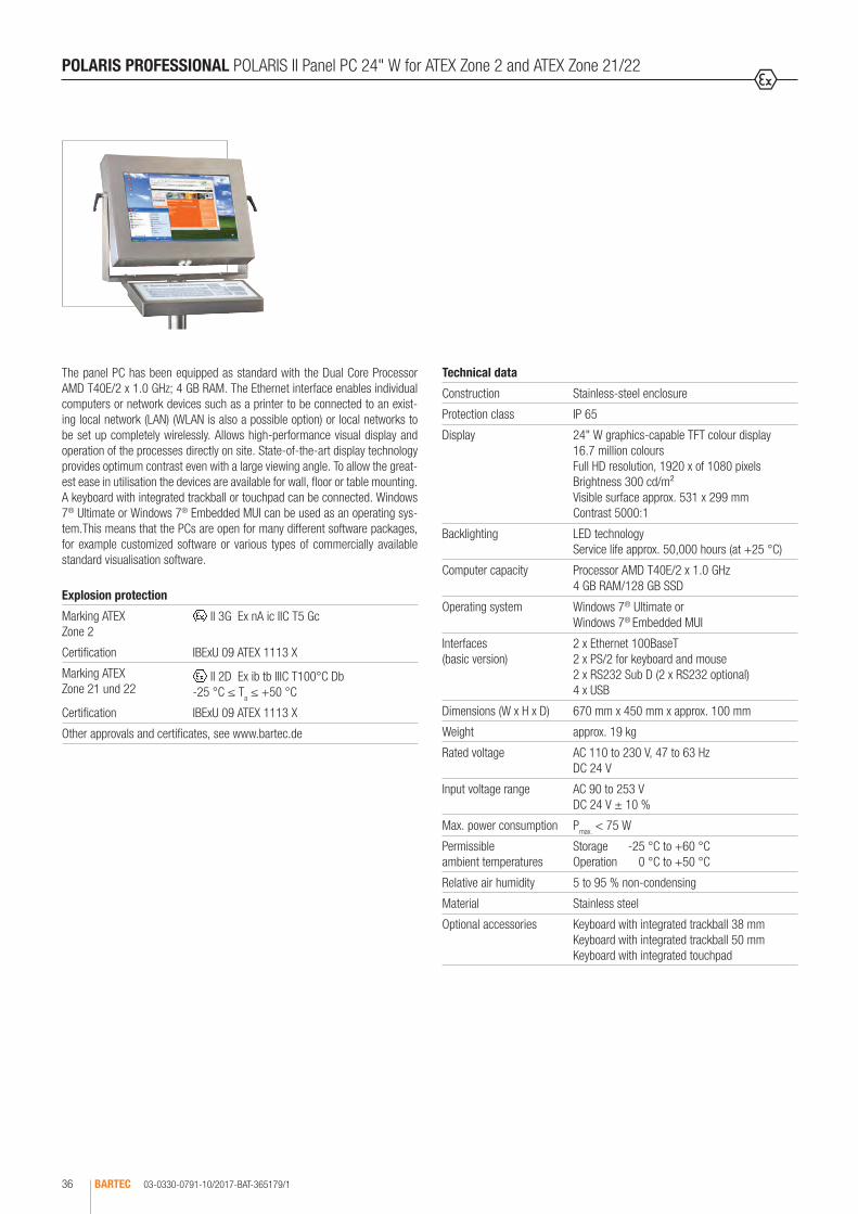
The panel PC has been equipped as standard with the Dual Core Processor AMD T40E/2 x 1.0 GHz; 4 GB RAM. The Ethernet interface enables individual computers or network devices such as a printer to be connected to an exist-ing local network (LAN) (WLAN is also a possible option) or local networks to be set up completely wirelessly. Allows high-performance visual display and operation of the processes directly on site. State-of-the-art display technology provides optimum contrast even with a large viewing angle. To allow the great-est ease in utilisation the devices are available for wall, floor or table mounting. A keyboard with integrated trackball or touchpad can be connected. Windows 7® Ultimate or Windows 7® Embedded MUI can be used as an operating sys-tem.This means that the PCs are open for many different software packages, for example customized software or various types of commercially available standard visualisation software.
POLARIS PROFESSIONAL POLARIS II Panel PC 24" W for ATEX Zone 2 and ATEX Zone 21/22
Technical data
Construction Stainless-steel enclosure
Protection class IP 65
Display 24" W graphics-capable TFT colour display 16.7 million colours Full HD resolution, 1920 x of 1080 pixels Brightness 300 cd/m² Visible surface approx. 531 x 299 mm Contrast 5000:1
Backlighting LED technology Service life approx. 50,000 hours (at +25 °C)
Computer capacity Processor AMD T40E/2 x 1.0 GHz 4 GB RAM/128 GB SSD
Operating system Windows 7® Ultimate or Windows 7® Embedded MUI
Interfaces (basic version)
2 x Ethernet 100BaseT 2 x PS/2 for keyboard and mouse 2 x RS232 Sub D (2 x RS232 optional) 4 x USB
Dimensions (W x H x D) 670 mm x 450 mm x approx. 100 mm
Weight approx. 19 kg
Rated voltage AC 110 to 230 V, 47 to 63 Hz DC 24 V
Input voltage range AC 90 to 253 V DC 24 V ± 10 %
Max. power consumption Pmax. < 75 W
Permissible ambient temperatures
Storage -25 °C to +60 °C Operation 0 °C to +50 °C
Relative air humidity 5 to 95 % non-condensing
Material Stainless steel
Optional accessories Keyboard with integrated trackball 38 mm Keyboard with integrated trackball 50 mm Keyboard with integrated touchpad
Explosion protection
Marking ATEX Zone 2
II 3G Ex nA ic IIC T5 Gc
Certification IBExU 09 ATEX 1113 X
Marking ATEX Zone 21 und 22
II 2D Ex ib tb IIIC T100°C Db -25 °C ≤ Ta ≤ +50 °C
Certification IBExU 09 ATEX 1113 X
Other approvals and certificates, see www.bartec.de

03-0330-0791-10/2017-BAT-365179/2 BARTEC 37
1
POLARIS PROFESSIONAL POLARIS II Panel PC 24" W for ATEX Zone 2 and ATEX Zone 21/22
Safe areaConnection example
PLC
Ethernet
Complete order no. 17-72 V4-8 2/ 00 POLARIS II Panel PC 24" W without touchscreenPlease insert correct code. Technical data subject to change without notice. Other versions on request.
Ordering information
Description Code no.
Input voltage Code no.
Operating system Code no.
POLARIS II Panel PC 24" W without touchscreen
4 AC 90 to 253 V 1 Windows 7® Ultimate
U
POLARIS II Panel PC 24" W with touchscreen
3 DC 24 V 2 Windows 7®
Embedded MUIF
Keyboard language Code no.
Insert unit Code no.
German 1 Trackball 50 mm
1
English 2 Trackball 38 mm
2
French 3 Touchpad 3

03-0330-0921-10/2017-BAT-414800BARTEC38
POLARIS SMART HMI 7" W Smart Keyboard/Ex i memory stick
Technical data
Product type 62T-ES16
Layout Front panel installation
Material Stainless steel
Protection class IP 65 (front side)
Dimensions (B x H) 219 mm x 115 mm
Wall cutout (B x H) 391 mm x 140 mm
Installed depth 21.5 mm
Connection USB
Keyboard with 62 keys, available in different languages
Technical data
Product type USB Flash drive
Memory capacity 8 GB
Dimensions (L x B x T) approx. 34 mm x 11 mm x 4 mm
Weight < 15 g
Enclosure material Plastic/sheet steel
Use Data backup and Ex i recovery stick
Explosion protection
Marking ATEX II 2G Ex ib IIC T4 Gb II 2D Ex ib IIIC T120°C Db
-20 °C ≤ Ta ≤ +60 °C
Certification IBExU 05 ATEX 1117 X
Marking IECEx Ex ib IIC T4 GbEx ib IIIC T120 °C Db
Certification IECEx IBE 11.0007X
Other approvals and certificates, see www.bartec.de
Explosion protection
Marking ATEX II 2G Ex ib IIC T4 Gb -20 °C ≤ Ta ≤ 50 °C
Certification DEMKO 16 ATEX 1803 Rev. 0
Marking IECEx Ex ib IIC T4 Gb
Certification IECEx UL 16.0160
Other approvals and certificates, see www.bartec.de
Ordering information
Smart keyboard 17-71VZ-C011
Technical data subject to change without notice.
Ordering information
Ex i memory stick 17-A1Z0-0007
Technical data subject to change without notice.
The intrinsically safe keyboard made of stainless steel is approved for the POLARIS Smart HMI 7" W for zone 1/21 and for zone 2/22. It is connected directly to the intrinsically safe USB port. The keyboard can also be connected to the complete POLARIS series. The keyboard is completely made of stain-less steel and has been developed for extreme industrial conditions (virtually insensitive to force), and its long-travel keys make it very comfortable to use. The keyboard is available in different languages.
Intrinsically safe Ex i memory stick. Approved for Agile X IS and POLARIS Smart HMI 7" W. May be replaced in explosive areas.
03-0330-0920-10/2017-BAT-414794 BARTEC 39
1
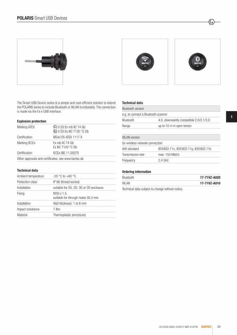
Ordering information
Bluetooth 17-71VZ-A020
WLAN 17-71VZ-A010
Technical data subject to change without notice.
Technical data
Ambient temperature -20 °C to +60 °C
Protection class IP 66 (thread socket)
Installation suitable for 2G, 2D, 3G or 3D enclosure
Fixing M30 x 1.5, suitable for through-holes 30.3 mm
Installation Wall thickness: 1 to 6 mm
Impact resistance 7 Nm
Material Thermoplastic (enclosure)
Technical data
Bluetooth version
e.g. to connect a Bluetooth scanner
Bluetooth 4.0, downwardly compatible 2.0/2.1/3.0
Range up to 10 m in open terrain
WLAN version
for wireless network connection
Wifi standard IEEE802.11n, IEEE802.11g, IEEE802.11b
Transmission rate max. 150 Mbit/s
Frequency 2.4 GHz
Explosion protection
Marking ATEX II 2G Ex mb IIC T4 Gb II 2D Ex IIIC T120 °C Db
Certification IBExU 05 ATEX 1117 X
Marking IECEx Ex mb IIC T4 GbEx IIIC T120 °C Db
Certification IECEx IBE 11.0007X
Other approvals and certificates, see www.bartec.de
POLARIS Smart USB Devices
The Smart USB Device series is a simple and cost-efficient solution to extend the POLARIS series to include Bluetooth or WLAN functionality. The connection is made via the Ex e USB interface.
03-0330-0407-10/2017-BAT-242769BARTEC40
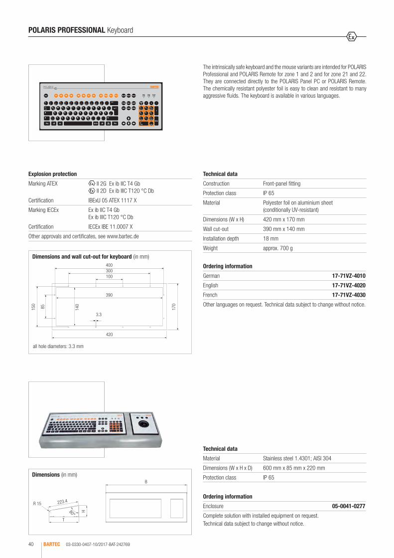
Dimensions and wall cut-out for keyboard (in mm)
all hole diameters: 3.3 mm
400300100
390
420
85150
140
3.3
170
Dimensions (in mm)
H80°
223.4
T
B
R 15
The intrinsically safe keyboard and the mouse variants are intended for POLARIS Professional and POLARIS Remote for zone 1 and 2 and for zone 21 and 22. They are connected directly to the POLARIS Panel PC or POLARIS Remote. The chemically resistant polyester foil is easy to clean and resistant to many aggressive fluids. The keyboard is available in various languages.
POLARIS PROFESSIONAL Keyboard
Technical data
Construction Front-panel fitting
Protection class IP 65
Material Polyester foil on aluminium sheet (conditionally UV-resistant)
Dimensions (W x H) 420 mm x 170 mm
Wall cut-out 390 mm x 140 mm
Installation depth 18 mm
Weight approx. 700 g
Technical data
Material Stainless steel 1.4301; AISI 304
Dimensions (W x H x D) 600 mm x 85 mm x 220 mm
Protection class IP 65
Explosion protection
Marking ATEX II 2G Ex ib IIC T4 Gb II 2D Ex ib IIIC T120 °C Db
Certification IBExU 05 ATEX 1117 X
Marking IECEx Ex ib IIC T4 Gb Ex ib IIIC T120 °C Db
Certification IECEx IBE 11.0007 X
Other approvals and certificates, see www.bartec.de
Ordering information
Enclosure 05-0041-0277
Complete solution with installed equipment on request.Technical data subject to change without notice.
Ordering information
German 17-71VZ-4010
English 17-71VZ-4020
French 17-71VZ-4030
Other languages on request. Technical data subject to change without notice.

03-0330-0445-10/2017-BAT-242770 BARTEC 41
1
all hole diameters: 3.3 mm
Dimensions and wall cut-out (mm)
130
170
100
110
150
85 140
3.3
POLARIS PROFESSIONAL Mouse, Trackball, Joystick and Touchpad
POLARIS Mouse, Trackball, Joystick and Touchpad
Explosion protection
Marking ATEX II 2G Ex ib IIC T4 Gb II 2D Ex ib IIIC T120 °C Db
Certification IBExU 05 ATEX 1117 X
Marking IECEx Ex ib IIC T4 Gb Ex ib IIIC T120 °C Db
Certification IECEx IBE 11.0007 X
Other approvals and certificates, see www.bartec.de
POLARIS Touchpad
Technical data
Construction Capacitive touchpad for Front-panel fitting
Protection class IP 65
Material Polyester foil on aluminium sheet (conditionally UV-resistant)
Dimensions (W x H)
130 mm x 170 mm
Wall cut-out 100 mm x 140 mm
Installation depth 15 mm
Weight approx. 250 g
Ordering information
Mouse 17-71VZ-1000
Trackball 17-71VZ-2000
Touchpad 17-71VZ-3000
Joystick with button 17-71VZ-9000
Technical data subject to change without notice.
POLARIS Mouse
Technical data
Construction Front-panel fitting
Protection class IP 65
Material Polyester foil on aluminium sheet (conditionally UV-resistant)
Dimensions (W x H)
130 mm x 170 mm
Wall cut-out 100 mm x 140 mm
Installation depth 15 mm
Weight approx. 270 g
POLARIS Trackball/Joystick
Technical data
Construction Front-panel fitting
Protection class Trackball (front side) static IP 65dynamic IP 56
Joystick IP 65
Material Polyester foil on aluminium sheet (conditionally UV-resistant)
Dimensions (W x H)
130 mm x 140 mm
Wall cut-out 100 mm x 140 mm
Installation depth 43 mm
Weight approx. 500 g
Bestellangaben
Abbildung Beschreibung Bestellnummer
Ex i memory-Stick 4 GB 17-71VZ-5000/0100
Recovery Stick auf Anfrage
Anschlusskabel für Tastatur- und Mausvarianten
Tastatur und Maus 1,8 m 05-0068-0163
Tastatur und Maus 3,0 m 05-0068-0204
Tastatur und Trackball/Joystick 1,8 m 05-0068-0172
Tastatur und Trackball/Joystick 3,0 m 05-0068-0205
Tastatur und Touchpad 1,8 m 05-0068-0183
Tastatur und Touchpad 3,0 m 05-0068-0206
Versteifungsrahmen
POLARIS Serie 10,4" 04-0205-0008
POLARIS Serie 12,1" 04-0205-0007
POLARIS Serie 12,1" W 05-0205-0008
POLARIS Serie 15" 05-0205-0009
POLARIS Serie 17,3" 05-0205-0013
POLARIS Serie 19,1" 05-0205-0010
POLARIS Serie 24" 05-0205-0012
Haltekrallensatz
4 Stück 05-0091-0111
6 Stück 05-0091-0112
LAN STP-Kabel
CAT.7 4 x 2 x 23 AWG, Außendurchmesser: 7,9 mm 02-4082-0002
CAT.7 4 x 2 x 22 AWG, Außendurchmesser: 18 mm; armiert 02-4082-0004
Hinweis: zusätzliche Kabelverschraubungen für Armierung erforderlich.
Originalverpackungen
POLARIS Serie 10,4" 04-9035-0005
POLARIS Serie 12,1" 04-9035-0006
POLARIS Serie 12,1" W 04-9035-0005
POLARIS Serie 15" 04-9035-0007
POLARIS Serie 17,3" auf Anfrage
POLARIS Serie 19,1" 04-9035-0008
POLARIS Serie 24" auf Anfrage
03-0330-0658-10/2017-BAT-318903/1BARTEC42
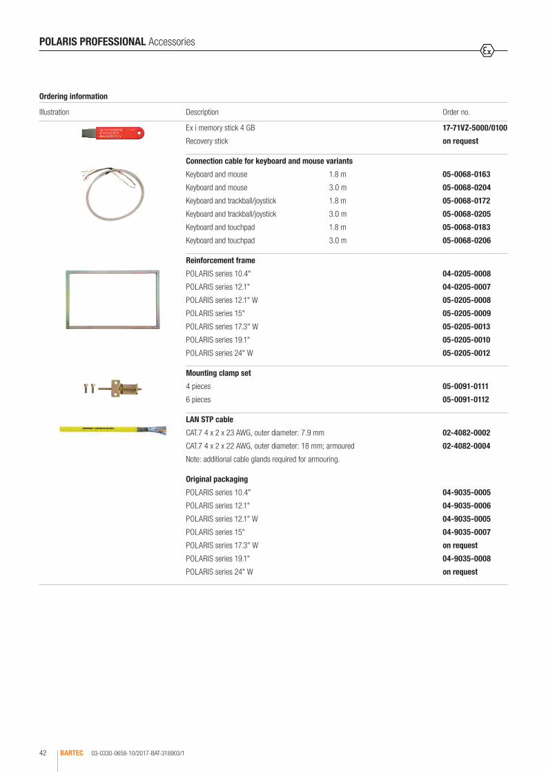
POLARIS PROFESSIONAL Accessories
Ordering information
Illustration Description Order no.
Ex i memory stick 4 GB 17-71VZ-5000/0100
Recovery stick on request
Connection cable for keyboard and mouse variants
Keyboard and mouse 1.8 m 05-0068-0163
Keyboard and mouse 3.0 m 05-0068-0204
Keyboard and trackball/joystick 1.8 m 05-0068-0172
Keyboard and trackball/joystick 3.0 m 05-0068-0205
Keyboard and touchpad 1.8 m 05-0068-0183
Keyboard and touchpad 3.0 m 05-0068-0206
Reinforcement frame
POLARIS series 10.4" 04-0205-0008
POLARIS series 12.1" 04-0205-0007
POLARIS series 12.1" W 05-0205-0008
POLARIS series 15" 05-0205-0009
POLARIS series 17.3" W 05-0205-0013
POLARIS series 19.1" 05-0205-0010
POLARIS series 24" W 05-0205-0012
Mounting clamp set
4 pieces 05-0091-0111
6 pieces 05-0091-0112
LAN STP cable
CAT.7 4 x 2 x 23 AWG, outer diameter: 7.9 mm 02-4082-0002
CAT.7 4 x 2 x 22 AWG, outer diameter: 18 mm; armoured 02-4082-0004
Note: additional cable glands required for armouring.
Original packaging
POLARIS series 10.4" 04-9035-0005
POLARIS series 12.1" 04-9035-0006
POLARIS series 12.1" W 04-9035-0005
POLARIS series 15" 04-9035-0007
POLARIS series 17.3" W on request
POLARIS series 19.1" 04-9035-0008
POLARIS series 24" W on request

1
B
H
T
03-0330-0658-10/2017-BAT-318903/2 BARTEC 43
1
POLARIS PROFESSIONAL Accessories
Ordering information
Illustration Description Dimensions in mm Order no.
Basic stainless-steel enclosure
Technical data
Material Stainless-steel 1.4404; AISI 316 L
Surface brushed
Protection class IP 65
• for floor mounting with stand (B x H x T)
POLARIS series 10.4" 560 x 320 x 200 07-56D7-9611/9002
POLARIS series 12.1" 600 x 350 x 200 07-56D7-9711/9002
POLARIS series 12.1" W 560 x 320 x 200 07-56D7-9611/9002
Complete solutions with fitted components on request
Standard stainless-steel enclosure
• with adapter connection without stand (B x H x T)
POLARIS series 15" 650 x 500 x 150 05-0041-0395
POLARIS series 15" Sunlight 650 x 500 x 150 05-0041-0395
POLARIS series 17.3" W 660 x 600 x 150 on request
POLARIS series 19.1" 760 x 600 x 150 05-0041-0994
POLARIS series 24" W 885 x 625 x 150 05-0041-0993
Basic stainless-steel enclosure
• for wall mounting with mounting straps (B x H x T)
POLARIS series 10,4" 560 x 320 x 200 07-56D7-9611/9001
POLARIS series 12,1" 600 x 350 x 200 07-56D7-9711/9001
POLARIS series 12,1" 560 x 320 x 200 07-56D7-9611/9001
POLARIS series 15" 650 x 500 x 210 07-56D7-0B11/9001
POLARIS series 15" Sunlight 650 x 500 x 210 07-56D7-0B11/9001
POLARIS series 19,1" 760 x 600 x 210 07-56D7-9A11/9001
¹ mounting strap for wall mounting

Bestellangaben
Abbildung Beschreibung Abmessungen in mm Bestellnummer
Edelstahlgehäuse Exklusiv II
Technische Daten
Material Edelstahl DIN 1.4301
• mit Adapteranschluss (B x H x T)
POLARIS Serie 15" 650 x 578 x 543 05-0041-0354
POLARIS Serie 17,3" 650 x 598 x 543 auf Anfrage
POLARIS Serie 19,1" 650 x 598 x 543 05-0041-0353
POLARIS Serie 24" 885 x 625 x 543 05-0041-0406
BH 120°
T
• Edelstahlgehäuse drehbar/neigbar • ohne Tischstandfuß
(B x H x T)
POLARIS Serie 15" 770 x 685 x 218 05-0041-0356
POLARIS Serie 19,1" 770 x 685 x 218 05-0041-0355
B
H
T
03-0330-0658-10/2017-BAT-318903/3BARTEC44
POLARIS PROFESSIONAL Accessories
Ordering information
Illustration Description Dimensions in mm Order no.
Exclusive II stainless-steel enclosure
Technical data
Material Stainless-steel grade 1.4301
• with adapter connection (B x H x T)
POLARIS series 15" 650 x 578 x 543 05-0041-0354
POLARIS series 17.3" W 650 x 598 x 543 on request
POLARIS series 19.1" 650 x 598 x 543 05-0041-0353
POLARIS series 24" W 885 x 625 x 543 05-0041-0406
• Stainless-steel enclosure - swivel/tilt • without desktop mount
(B x H x T)
POLARIS series 15" 770 x 685 x 218 05-0041-0356
POLARIS series 19.1" 770 x 685 x 218 05-0041-0355
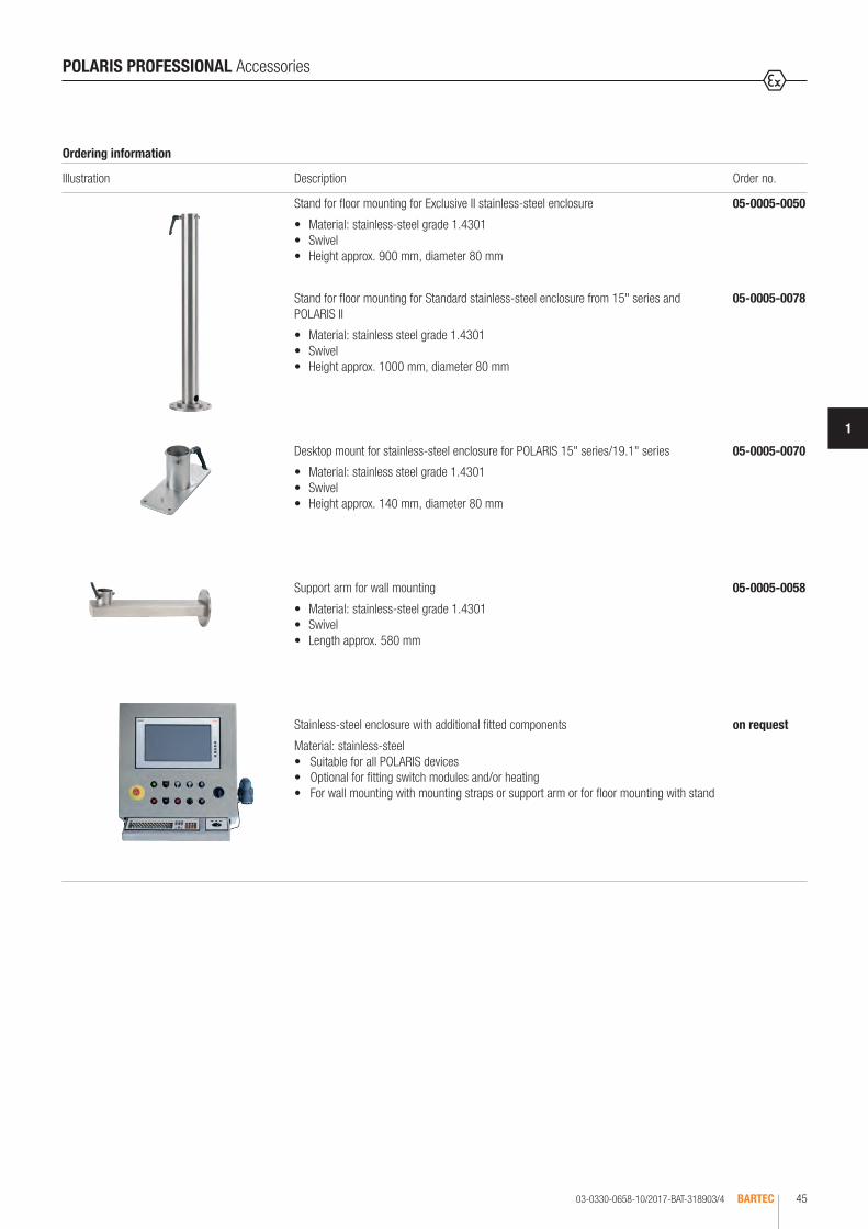
Bestellangaben
Abbildung Beschreibung Bestellnummer
Standfuß zur Bodenmontage für Edelstahlgehäuse Exklusiv II 05-0005-0050
• Material: Edelstahl DIN 1.4301• drehbar• Höhe ca. 900 mm, Durchmesser 80 mm
Standfuß zur Bodenmontage für Edelstahlgehäuse Standard ab 15" Serie und POLARIS II 05-0005-0078
• Material: Edelstahl DIN 1.4301• drehbar• Höhe ca. 1000 mm, Durchmesser 80 mm
Tischstandfuß für Edelstahlgehäuse für POLARIS 15" Serie/19,1" Serie 05-0005-0070
• Material: Edelstahl DIN 1.4301 • drehbar• Höhe ca. 140 mm, Durchmesser 80 mm
Tragarm zur Wandmontage 05-0005-0058
• Material: Edelstahl DIN 1.4301 • drehbar • Länge ca. 580 mm
Edelstahlgehäuse Standard mit zusätzlichen Einbauten auf Anfrage
Material: Edelstahl• für alle POLARIS Geräte geeignet• optional zum Einbau von Schaltmodulen und/oder Heizung• zur Wandmontage mit Befestigungslaschen oder Tragarm oder zur Bodenmontage mit Standfuß
03-0330-0658-10/2017-BAT-318903/4 BARTEC 45
1
POLARIS PROFESSIONAL Accessories
Ordering information
Illustration Description Order no.
Stand for floor mounting for Exclusive II stainless-steel enclosure 05-0005-0050
• Material: stainless-steel grade 1.4301 • Swivel • Height approx. 900 mm, diameter 80 mm
Stand for floor mounting for Standard stainless-steel enclosure from 15" series and POLARIS II
05-0005-0078
• Material: stainless steel grade 1.4301 • Swivel • Height approx. 1000 mm, diameter 80 mm
Desktop mount for stainless-steel enclosure for POLARIS 15" series/19.1" series 05-0005-0070
• Material: stainless steel grade 1.4301 • Swivel • Height approx. 140 mm, diameter 80 mm
Support arm for wall mounting 05-0005-0058
• Material: stainless-steel grade 1.4301 • Swivel • Length approx. 580 mm
Stainless-steel enclosure with additional fitted components on request
Material: stainless-steel • Suitable for all POLARIS devices • Optional for fitting switch modules and/or heating • For wall mounting with mounting straps or support arm or for floor mounting with stand

03-0330-0407/A-10/2017-BAT-236279/1BARTEC46
The POLARIS Remote 15" unit by BARTEC is a display which a PC can be oper-ated in safe areas of hazardous areas. Distances of up to 20 km are possible. POLARIS Remote 15" offers the user the possibility to use PC-based process control systems, without restrictions in hazardous areas. The front panel instal-lation assures ease of mounting. On request, the devices are also available as turn-key system solutions in a Stainless-steel enclosure as wall, floor or ceiling mounting versions. The screen of the Remote 15" is a TFT display with an XGA resolution and is characterised by its excellent brilliance and a very large read-ing angle. Intrinsically safe input devices can also be connected. The optional touchcreen (intrinsically safe) offers the ultimate in operating comfort. Connec-tion in the safe area is realised via a local unit (included in scope of delivery).
POLARIS REMOTE POLARIS Remote 15"
Technical data
Construction Front-panel fitting
Protection class IP 65 (front) IP 54 (back)
Display 15" graphics-capable TFT colour display 16.7 million colours XGA resolution 1024 x 768 pixels Brightness 350 cd/m2
Visible area approx. 304 x 228 mm Contrast 700:1 Antireflection-coated glass panel Optional touchscreen
Backlighting LED technology Service life approx. 50,000 hours (at +25 °C)
KVM connection to the PC via local unit
Explosion protection
Marking ATEX Zone 1 and 21
II 2G Ex db eb qb [ib op pr] IIC T4 II 2D Ex tb IIIC T120 °C
Certification IBExU 05 ATEX 1117 X
Marking IECEx Ex db eb qb [ib op pr] IIC T4 Ex tb IIIC T120 °C
Certification IECEx IBE 11.0007 X
Other approvals and certificates, see www.bartec.de
Variant for Zone 2 www.bartec.de
up to 300 m via STP/S copper cable VGA/PS2 (RS232 Touch) up to 100 m via STP/S copper cable DVI/USB up to 500 m via multi-mode fibre optic cable DVI/USB up to 20 km via single-mode fibre optic cable DVI/USB
Cable length POLARIS: terminals in the Ex e chamberLocal unit: RJ45 connectorUp to 300 m via STP copper cable VGA/PS2 (RS232 Touch)Up to 100 m via STP copper cable DVI/USB
Optical fibre versionPOLARIS: ST connector Local unit: LC connector Up to 500 m via multi-mode optical fibre (50 μm/125) DVI/USBUp to 20 km via single-mode optical fibre(9/125 μm) DVI/USB
Composite video Connection via Ex e terminals
Power supply AC 90 to 253 V, 50 to 60 Hz or DC 24 V ± 10 % on request or DC 12 V (9 to 18 V) on request
Max. power consumption Pmax. < 60 W
Optional accessories Hand-held scanner on request
Dimensions (W x H x D) 411 mm x 332 mm x approx. 135 mm
Wall cut-out 394.5 mm x 315.5 mm + 0.5 mm
Weight approx. 23 kg
Admissible ambient temperatures
Storage -20 °C to +50 °C Operation 0 °C to +50 °C System solution with heating on request.
Relative air humidity 5 to 95 % non-condensing
Vibration 0.7 g/1 mm; 5 Hz to 500 Hz pulse in all 3 axes
Shock 15 g/11 ms pulse in all 3 axes
Material Front: polyester foil on anodised aluminium plate (conditionally UV-resistant) Back: bichromated sheet steel
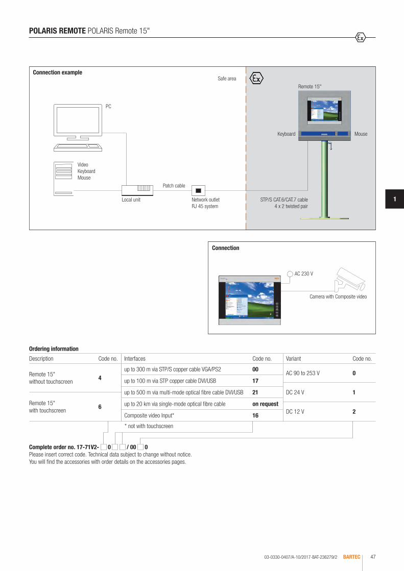
03-0330-0407/A-10/2017-BAT-236279/2 BARTEC 47
1
Connection example
Network outletRJ 45 system
Local unit
Patch cable
STP/S CAT.6/CAT.7 cable4 x 2 twisted pair
Keyboard Mouse
Remote 15"Safe area
PC
Video KeyboardMouse
POLARIS REMOTE POLARIS Remote 15"
* not with touchscreen
Ordering information
Description Code no. Interfaces Code no.
Remote 15" without touchscreen
4up to 300 m via STP/S copper cable VGA/PS2 00
up to 100 m via STP copper cable DVI/USB 17
up to 500 m via multi-mode optical fibre cable DVI/USB 21
Remote 15" with touchscreen
6 up to 20 km via single-mode optical fibre cable on request
Composite video Input* 16
Variant Code no.
AC 90 to 253 V 0
DC 24 V 1
DC 12 V 2
Complete order no. 17-71V2- 0 / 00 0 Please insert correct code. Technical data subject to change without notice. You will find the accessories with order details on the accessories pages.
Connection
AC 230 V
Camera with Composite video

03-0330-0407-10/2017-BAT-409551/1BARTEC48
The POLARIS Remote 15" unit by BARTEC is a display which a PC can be oper-ated in safe areas of hazardous areas. Distances of up to 20 km are possible. POLARIS Remote 15" offers the user the possibility to use PC-based process control systems, without restrictions in hazardous areas. The front panel instal-lation assures ease of mounting. On request, the devices are also available as turn-key system solutions in a Stainless-steel enclosure as wall, floor or ceiling mounting versions. The screen of the Remote 15" is a TFT display with an XGA resolution and is characterised by its excellent brilliance and a very large read-ing angle. Intrinsically safe input devices can also be connected. The optional touchcreen (intrinsically safe) offers the ultimate in operating comfort. Connec-tion in the safe area is realised via a local unit (included in scope of delivery).
Technical data
Construction Front-panel fitting
Protection class IP 65 (front) IP 54 (back)
Display 15" graphics-capable TFT colour display 262,144 colours XGA resolution, 1024 x 768 pixels Brightness 1000 cd/m2 Visible area approx. 304 x 228 mm Contrast 700:1 Antireflection-coated glass pane Optional touchscreen (resistive)
Backlighting LED technology Service life approx. 50,000 hours (at +25 °C)
KVM connection to the PC via local unit
Explosion protection
Marking ATEX Zone 1 and 21
II 2G Ex db eb q [ib] IIC T4 Gb II 2D Ex tb IIIC T120 °C Db
Certification IBExU 05 ATEX 1117 X
Marking IECEx Ex db eb q [ib] IIC T4 Gb Ex tb IIIC T120 °C Db
Certification IECEx IBE 11.0007 X
Other approvals and certificates, see www.bartec.de
Variant for Zone 2 www.bartec.de
POLARIS REMOTE POLARIS Remote 15" Sunlight
Cable length POLARIS: terminals in the Ex e chamberLocal unit: RJ45 connectorUp to 300 m via STP copper cable VGA/PS2 (RS232 Touch)Up to 100 m via STP copper cable DVI/USB
Optical fibre versionPOLARIS: ST connector Local unit: LC connector Up to 500 m via multi-mode optical fibre (50 μm/125) DVI/USBUp to 20 km via single-mode optical fibre(9/125 μm) DVI/USB
Composite video Connection via Ex e terminals
Power supply AC 90 to 253 V, 50 to 60 Hz or DC 24 V ± 10 % on request or DC 12 V (9 to 18 V) on request
Max. power consumption Pmax. < 60 W
Optional accessories Hand-held scanner on request
Dimensions (W x H x D) 411 mm x 332 mm x approx. 135 mm
Wall cut-out 394.5 mm x 315.5 mm + 0.5 mm
Weight approx. 23 kg
Admissible ambient temperatures
Storage -20 °C to +50 °C Operation 0 °C to +50 °C System solution with heating on request.
Relative air humidity 5 to 95 % non-condensing
Vibration 0.7 g/1 mm; 5 Hz to 500 Hz pulse in all 3 axes
Shock 15 g/11 ms pulse in all 3 axes
Material Front: polyester foil on anodised aluminium plate (conditionally UV-resistant) Back: bichromated sheet steel

03-0330-0407-10/2017-BAT-409551/2 BARTEC 49
1
Connection example
Network outletRJ 45 system
Local unit
Patch cable
STP/S CAT.6/CAT.7 cable4 x 2 twisted pair
Keyboard Mouse
Remote 15"
Safe area
PC
Video KeyboardMouse
POLARIS REMOTE POLARIS Remote 15" Sunlight
* not with touchscreen
Ordering information
Description Code no. Interfaces Code no.
Remote 15" Sunlight without touchscreen
4up to 300 m via STP/S copper cable VGA/PS2 00
up to 100 m via STP copper cable DVI/USB 17
up to 500 m via multi-mode optical fibre cable DVI/USB 21
Remote 15" Sunlight with touchscreen
6 up to 20 km via single-mode optical fibre cable on request
Composite video Input* 16
Variant Code no.
AC 90 to 253 V 0
DC 24 V 1
DC 12 V 2
Complete order no. 17-71V2- 0 / 00 0 Please insert correct code. Technical data subject to change without notice. You will find the accessories with order details on the accessories pages.
AC 230 V
Camera with Composite video
Connection

03-0330-0408-10/2017-BAT-236280/1BARTEC50
The POLARIS Remote 19.1" unit by BARTEC is a display which a PC can be operated in safe areas of hazardous areas.Distances of up to 10000 m are possible. POLARIS Remote 19.1" offers the user the possibility of using any currently available PC-based process control system, without any restrictions in the Ex area. The front panel installation assures ease of mounting. On request, the devices are also available as turn-key system solutions in a Stainless-steel enclosure as wall, floor or ceiling mounting versions. The screen of the Remote 19.1" is a TFT display with an SXGA resolution and is characterised by its ex-cellent brilliance and a very large reading angle.Intrinsically safe input devices can also be connected. The optional touchcreen (intrinsically safe) offers the ultimate in operating comfort. Connection in the safe area is realised via a local unit (included in scope of delivery).
POLARIS REMOTE POLARIS Remote 19.1"
Technical data
Construction Front-panel fitting
Protection class IP 65 (front) IP 54 (back)
Display 19.1" graphics-capable TFT colour display 16.7 million colours SXGA resolution 1280 x 1024 pixels Brightness 300 cd/m2
Visible area approx. 380 x 305 mm Contrast 1300:1 Antireflection-coated glass pane Optional touchscreen
Backlighting LED technology Service life approx. 40,000 hours (at +25 °C)
Explosion protection
Marking ATEX Zone 1 und 21
II 2G Ex db eb qb [ib op pr] IIC T4 II 2D Ex tb IIIC T120 °C
Certification IBExU 05 ATEX 1117 X
Marking IECEx Ex db eb qb [ib op pr] IIC T4 Ex tb IIIC T120 °C
Certification IECEx IBE 11.0007 X
Other approvals and certificates, see www.bartec.de
Variant for Zone 2 www.bartec.de
Requirement to the base station
Keyboard and mouse with a PS/2 connector; VGA connection or graphics card with the following technical data: - VGA, SVGA, XGA, SXGA resolution - Vertical sync frequency 60 to 75 Hz
Cable length POLARIS: terminals in the Ex e chamberLocal unit: RJ45 connectorUp to 300 m via STP copper cable VGA/PS2 (RS232 Touch)Up to 100 m via STP copper cable DVI/USB
Optical fibre versionPOLARIS: ST connector Local unit: LC connector Up to 500 m via multi-mode optical fibre (50 μm/125) DVI/USBUp to 20 km via single-mode optical fibre(9/125 μm) DVI/USB
Power supply AC 90 to 253 V, 50 to 60 Hz DC 24 V ± 10 % on request
Max. power consumption Pmax. < 60 W
Optional accessories Hand-held scanner on request
Dimensions (W x H x D) 498 mm x 400 mm x approx. 135 mm
Wall cut-out 484 mm x 386.5 mm + 0.5 mm
Weight approx. 33 kg
Admissible ambient temperatures
Storage -20 °C to +50 °C Operation 0 °C to +50 °C System solution with heating on request.
Relative air humidity 5 to 95 % non-condensing
Vibration 0.7 g/1 mm; 5 Hz to 500 Hz pulse in all 3 axes
Shock 15 g/11 ms pulse in all 3 axes
Material Front: polyester foil on anodised aluminium plate (conditionally UV-resistant) Back: bichromated sheet steel
Optionales Zubehör Handscanner auf Anfrage
Optional accessories Hand-held scanner on request

1
03-0330-0408-10/2017-BAT-236280/2 BARTEC 51
POLARIS REMOTE POLARIS Remote 19.1"
Connection example
Network outletRJ 45 system
Local unit
Patch cable
STP/S CAT.6/CAT.7 cable4 x 2 twisted pair
Keyboard Mouse
Remote 19,1"
Safe area
PC
Video KeyboardMouse
* not with touchscreen
Complete order no. 17-71V2- 0 / 00 0 Please insert correct code. Technical data subject to change without notice. You will find the accessories with order details on the accessories pages.
Ordering information
Description Code no. Interfaces Code no.
Remote 19.1" without touchscreen
5up to 300 m via STP/S copper cable VGA/PS2 00
up to 100 m via STP copper cable DVI/USB 17
up to 500 m via multi-mode optical fibre cable DVI/USB 21
Remote 19.1" with touchscreen
7 up to 20 km via single-mode optical fibre cable on request
Composite video Input* 16
Bestellangaben
Variant Code no.
AC 90 to 253 V 0
DC 24 V 1

03-0330-0688/A-10/2017-BAT-334209/1BARTEC52
The POLARIS Remote 24" W unit by BARTEC is a display which a PC can be operated in safe areas of hazardous areas. Distances of up to 10000 m are possible. POLARIS Remote 24" W offers the user the possibility of using any currently available PC-based process control system, without any restrictions in the Ex area. The front panel installation assures ease of mounting. On request, the devices are also available as turn-key system solutions in a Stainless-steel enclosure as wall, floor or ceiling mounting versions. The screen of the Remote 24" W is a TFT display with an Full HD resolution and is characterised by its excellent brilliance and a very large reading angle. Intrinsically safe input devices can also be connected. The optional touchcreen (intrinsically safe) offers the ultimate in operating comfort. Connection in the safe area is realised via a local unit (included in scope of delivery).
POLARIS REMOTE POLARIS Remote 24" W
Technical data
Construction Front-panel fitting
Protection class IP 65 (front) IP 54 (back)
Display 24" W graphics-capable TFT colour display 16.7 million colours Full HD resolution 1920 x 1080 pixels Brightness 300 cd/m2
Visible area approx. 531 x 299 mm Contrast 3000:1 Antireflection-coated glass pane Optional touchscreen
Backlighting LED technology Service life approx. 50,000 hours (at +25 °C)
Cable length up to 100 m via STP copper cable DVI/USB up to 20 km via optical fibers Single Mode (9/125 μm) DVI/USB
Power supply AC 90 to 253 V, 50 to 60 Hz DC 24 V ± 10 % on request
Max. power consumption Pmax. < 60 W
Optional accessories Hand-held scanner on request
Dimensions (W x H x D) 644 mm x 406 mm x approx. 135 mm
Wall cut-out 630 mm x 392 mm + 0.5 mm
Weight approx. 40 kg
Admissible ambient temperatures
Storage -20 °C to +50 °C Operation 0 °C to +50 °C System solution with heating on request.
Relative air humidity 5 to 95 % non-condensing
Vibration 0.7 g/1 mm; 5 Hz to 500 Hz pulse in all 3 axes
Shock 15 g/11 ms pulse in all 3 axes
Material Front: polyester foil on anodised aluminium plate (conditionally UV-resistant) Back: bichromated sheet steel
Explosion protection
Marking ATEX Zone 1 and 21
II 2G Ex db eb q [ib] IIC T4 Gb II 2D Ex tb IIIC T120 °C Db
Certification IBExU 05 ATEX 1117 X
Marking IECEx Ex db eb q [ib] IIC T4 Gb Ex tb IIIC T120 °C Db
Certification IECEx IBE 11.0007 X
Other approvals and certificates, see www.bartec.de
Variant for Zone 2 www.bartec.deOptionales Zubehör Handscanner auf Anfrage
Optional accessories Hand-held scanner on request

03-0330-0688/A-10/2017-BAT-334209/2 BARTEC 53
1
POLARIS REMOTE POLARIS Remote 24" W
Connection example
Network outletRJ 45 system
Local unit
Patch cable
STP/S CAT.6/CAT.7 cable4 x 2 twisted pair
Remote 24" W
Safe area
PC
Video KeyboardMouse
* not with touchscreen
Ordering information
Description Code no. Interfaces Code no.
Remote 24" W without touchscreen
C for STP/S copper cable(up to max. 100 m) 17
for 50 µm multi-mode optical fibre cable (up to max. 500 m) on requestRemote 24" W with touchscreen
D up to 20 km via single-mode optical fibre cable on request
Bestellangaben
Variant Code no.
AC 90 to 253 V 0
DC 24 V 1
Complete order no. 17-71V2- 0 / 00 0Please insert correct code. Technical data subject to change without notice. You will find the accessories with order details on the accessories pages.
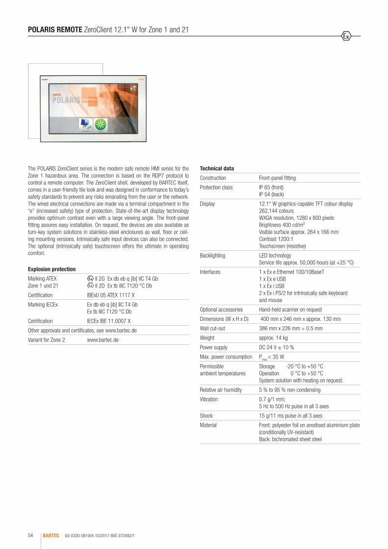
03-0330-0819/A-10/2017-BAT-372482/1BARTEC54
The POLARIS ZeroClient series is the modern safe remote HMI series for the Zone 1 hazardous area. The connection is based on the RDP7 protocol to control a remote computer. The ZeroClient shell, developed by BARTEC itself, comes in a user-friendly tile look and was designed in conformance to today’s safety standards to prevent any risks emanating from the user or the network.The wired electrical connections are made via a terminal compartment in the “e” (increased safety) type of protection. State-of-the-art display technology provides optimum contrast even with a large viewing angle. The front-panel fitting assures easy installation. On request, the devices are also available as turn-key system solutions in stainless-steel enclosures as wall, floor or ceil-ing mounting versions. Intrinsically safe input devices can also be connected. The optional (intrinsically safe) touchscreen offers the ultimate in operating comfort.
POLARIS REMOTE ZeroClient 12.1" W for Zone 1 and 21
Technical data
Construction Front-panel fitting
Protection class IP 65 (front) IP 54 (back)
Display 12.1" W graphics-capable TFT colour display 262,144 colours WXGA resolution, 1280 x 800 pixels Brightness 400 cd/m² Visible surface approx. 264 x 166 mm Contrast 1200:1 Touchscreen (resistive)
Backlighting LED technology Service life approx. 50,000 hours (at +25 °C)
Interfaces 1 x Ex e Ethernet 100/10BaseT 1 x Ex e USB 1 x Ex i USB 2 x Ex i PS/2 for intrinsically safe keyboard and mouse
Optional accessories Hand-held scanner on request
Dimensions (W x H x D) 400 mm x 246 mm x approx. 130 mm
Wall cut-out 386 mm x 226 mm + 0.5 mm
Weight approx. 14 kg
Power supply DC 24 V ± 10 %
Max. power consumption Pmax.< 35 W
Permissible ambient temperatures
Storage -20 °C to +50 °C Operation 0 °C to +50 °C System solution with heating on request.
Relative air humidity 5 % to 95 % non-condensing
Vibration 0.7 g/1 mm; 5 Hz to 500 Hz pulse in all 3 axes
Shock 15 g/11 ms pulse in all 3 axes
Material Front: polyester foil on anodised aluminium plate (conditionally UV-resistant) Back: bichromated sheet steel
Explosion protection
Marking ATEX Zone 1 und 21
II 2G Ex db eb q [ib] IIC T4 Gb II 2D Ex tb IIIC T120 °C Db
Certification IBExU 05 ATEX 1117 X
Marking IECEx Ex db eb q [ib] IIC T4 Gb Ex tb IIIC T120 °C Db
Certification IECEx IBE 11.0007 X
Other approvals and certificates, see www.bartec.de
Variant for Zone 2 www.bartec.de
Optionales Zubehör Handscanner auf Anfrage
Optional accessories Hand-held scanner on request

03-0330-0819/A-10/2017-BAT-372482/2 BARTEC 55
1
PC, server, virtual PC
ZeroClient 12.1" W
Keyboard Mouse
Ethernet
POLARIS REMOTE ZeroClient 12.1" W for Zone 1 and 21
Connection exampleSafe area
Ordering information
POLARIS REMOTE ZeroClient 12.1" W with touchscreen
17-71V1-B436/Z000
Technical data subject to change without notice. You will find the accessories with order details on the accessories pages.

03-0330-0817/A-10/2017-BAT-372480/1BARTEC56
The POLARIS ZeroClient series is the modern safe remote HMI series for the Zone 1 hazardous area. The connection is based on the RDP7 protocol to control a remote computer. The ZeroClient shell, developed by BARTEC itself, comes in a user-friendly tile look and was designed in conformance to today’s safety standards to prevent any risks emanating from the user or the network. The wired electrical connections are made via a terminal compart-ment in the “e” (increased safety) type of protection. State-of-the-art display technology provides optimum contrast even with a large viewing angle. The front-panel fitting assures easy installation. On request, the devices are also available as turn-key system solutions in stainless-steel enclosures as wall, floor or ceiling mounting versions. Intrinsically safe input devices can also be connected. The optional (intrinsically safe) touchscreen offers the ultimate in operating comfort.
POLARIS REMOTE ZeroClient 15" for Zone 1 and 21
Technical data
Construction Front-panel fitting
Protection class IP 65 (front) IP 54 (back)
Display 15" graphics-capable TFT colour display 16.7 million colours XGA resolution 1024 x 768 pixels Brightness 50 cd/m2
Visible area approx. 304 x 228 mm Contrast 700:1 Antireflection-coated glass pane Optional touchscreen (resistive)
Backlighting LED technology Service life approx. 50,000 hours (at +25 °C)
Interfaces 1 x Ex e Ethernet 100/10BaseT (optical fibres optional) 1 x Ex e USB 1 x Ex i USB 2 x Ex i PS/2 for intrinsically safe keyboard and mouse
Optional accessories Hand-held scanner on request
Dimensions (W x H x D) 411 mm x 332 mm x approx. 135 mm
Wall cut-out 394.5 mm x 315.5 mm + 0.5 mm
Weight approx. 23 kg
Power supply DC 24 V ± 10 % AC 100 to 230 V, 50 to 60 Hz
Input voltage range DC 24 V ± 10 % AC 90 V to 253 V
Max. power consumption Pmax. < 70 W
Admissible ambient temperatures
Storage -20 °C to +50 °C Operation 0 °C to +50 °C System solution with heating on request.
Relative air humidity 5 to 95 % non-condensing
Vibration 0.7 g/1 mm; 5 Hz to 500 Hz pulse in all 3 axes
Shock 15 g/11 ms pulse in all 3 axes
Material Front: polyester foil on anodised aluminium plate (conditionally UV-resistant) Back: bichromated sheet steel
Explosion protection
Marking ATEX Zone 1 and 21
II 2G Ex db eb q [ib] IIC T4 Gb II 2D Ex tb IIIC T120 °C Db
Certification IBExU 05 ATEX 1117 X
Marking IECEx Ex db eb q [ib] IIC T4 Gb Ex tb IIIC T120 °C Db
Certification IECEx IBE 11.0007 X
Other approvals and certificates, see www.bartec.de
Variant for Zone 2 www.bartec.de

03-0330-0817/A-10/2017-BAT-372480/2 BARTEC 57
1
PC, server, virtual PC
ZeroClient 15" W
Keyboard Mouse
Ethernet
POLARIS REMOTE ZeroClient 15" for Zone 1 and 21
Connection exampleSafe area
Ordering information
Description Code no. Input voltage range Code no.
ZeroClient 15" without touchscreen 4 AC 90 to 253 V 0
ZeroClient 15" with touchscreen 6 DC 24 V 2
Complete order no. 17-71V1- 072/Z000/ 200 Please insert correct code. Technical data subject to change without notice. You will find the accessories with order details on the accessories pages.
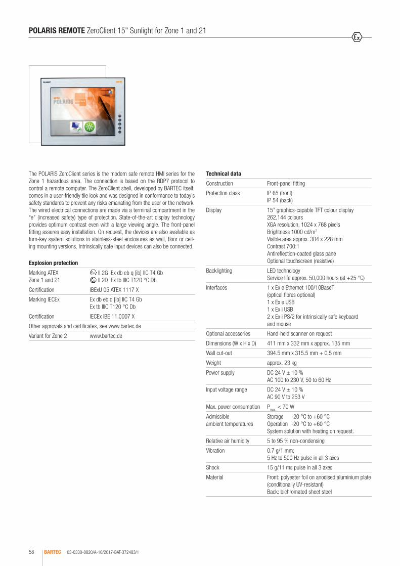
03-0330-0820/A-10/2017-BAT-372483/1BARTEC58
The POLARIS ZeroClient series is the modern safe remote HMI series for the Zone 1 hazardous area. The connection is based on the RDP7 protocol to control a remote computer. The ZeroClient shell, developed by BARTEC itself, comes in a user-friendly tile look and was designed in conformance to today’s safety standards to prevent any risks emanating from the user or the network. The wired electrical connections are made via a terminal compartment in the “e” (increased safety) type of protection. State-of-the-art display technology provides optimum contrast even with a large viewing angle. The front-panel fitting assures easy installation. On request, the devices are also available as turn-key system solutions in stainless-steel enclosures as wall, floor or ceil-ing mounting versions. Intrinsically safe input devices can also be connected.
POLARIS REMOTE ZeroClient 15" Sunlight for Zone 1 and 21
Technical data
Construction Front-panel fitting
Protection class IP 65 (front) IP 54 (back)
Display 15” graphics-capable TFT colour display 262,144 colours XGA resolution, 1024 x 768 pixels Brightness 1000 cd/m2 Visible area approx. 304 x 228 mm Contrast 700:1 Antireflection-coated glass pane Optional touchscreen (resistive)
Backlighting LED technology Service life approx. 50,000 hours (at +25 °C)
Interfaces 1 x Ex e Ethernet 100/10BaseT (optical fibres optional) 1 x Ex e USB 1 x Ex i USB 2 x Ex i PS/2 for intrinsically safe keyboard and mouse
Optional accessories Hand-held scanner on request
Dimensions (W x H x D) 411 mm x 332 mm x approx. 135 mm
Wall cut-out 394.5 mm x 315.5 mm + 0.5 mm
Weight approx. 23 kg
Power supply DC 24 V ± 10 % AC 100 to 230 V, 50 to 60 Hz
Input voltage range DC 24 V ± 10 % AC 90 V to 253 V
Max. power consumption Pmax. < 70 W
Admissible ambient temperatures
Storage -20 °C to +60 °C Operation -20 °C to +60 °C System solution with heating on request.
Relative air humidity 5 to 95 % non-condensing
Vibration 0.7 g/1 mm; 5 Hz to 500 Hz pulse in all 3 axes
Shock 15 g/11 ms pulse in all 3 axes
Material Front: polyester foil on anodised aluminium plate (conditionally UV-resistant) Back: bichromated sheet steel
Explosion protection
Marking ATEX Zone 1 and 21
II 2G Ex db eb q [ib] IIC T4 Gb II 2D Ex tb IIIC T120 °C Db
Certification IBExU 05 ATEX 1117 X
Marking IECEx Ex db eb q [ib] IIC T4 Gb Ex tb IIIC T120 °C Db
Certification IECEx IBE 11.0007 X
Other approvals and certificates, see www.bartec.de
Variant for Zone 2 www.bartec.de

03-0330-0820/A-10/2017-BAT-372483/2 BARTEC 59
1
PC, server, virtual PC
ZeroClient 15" Sunlight
Keyboard Mouse
Ethernet
POLARIS REMOTE ZeroClient 15" Sunlight for Zone 1 and 21
Connection exampleSafe area
Ordering information
Description Input voltage range Code no.
ZeroClient 15" Sunlight with touchscreen
AC 90 to 253 V 0
DC 24 V 2
Complete order no. 17-71V1-6272/Z000/ 200Please insert correct code. Technical data subject to change without notice. You will find the accessories with order details on the accessories pages.
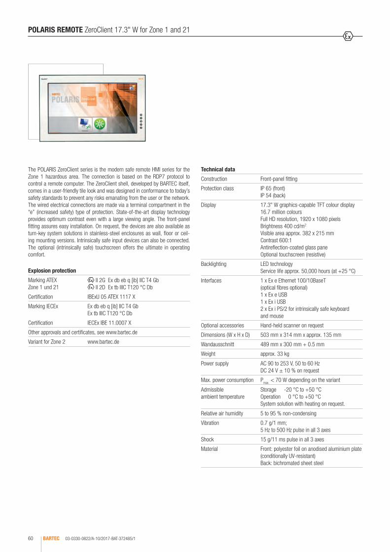
03-0330-0822/A-10/2017-BAT-372485/1BARTEC60
The POLARIS ZeroClient series is the modern safe remote HMI series for the Zone 1 hazardous area. The connection is based on the RDP7 protocol to control a remote computer. The ZeroClient shell, developed by BARTEC itself, comes in a user-friendly tile look and was designed in conformance to today’s safety standards to prevent any risks emanating from the user or the network. The wired electrical connections are made via a terminal compartment in the “e” (increased safety) type of protection. State-of-the-art display technology provides optimum contrast even with a large viewing angle. The front-panel fitting assures easy installation. On request, the devices are also available as turn-key system solutions in stainless-steel enclosures as wall, floor or ceil-ing mounting versions. Intrinsically safe input devices can also be connected. The optional (intrinsically safe) touchscreen offers the ultimate in operating comfort.
POLARIS REMOTE ZeroClient 17.3" W for Zone 1 and 21
Technical data
Construction Front-panel fitting
Protection class IP 65 (front) IP 54 (back)
Display 17.3" W graphics-capable TFT colour display 16.7 million colours Full HD resolution, 1920 x 1080 pixels Brightness 400 cd/m2
Visible area approx. 382 x 215 mm Contrast 600:1 Antireflection-coated glass pane Optional touchscreen (resistive)
Backlighting LED technology Service life approx. 50,000 hours (at +25 °C)
Interfaces 1 x Ex e Ethernet 100/10BaseT (optical fibres optional) 1 x Ex e USB 1 x Ex i USB 2 x Ex i PS/2 for intrinsically safe keyboard and mouse
Optional accessories Hand-held scanner on request
Dimensions (W x H x D) 503 mm x 314 mm x approx. 135 mm
Wandausschnitt 489 mm x 300 mm + 0.5 mm
Weight approx. 33 kg
Power supply AC 90 to 253 V, 50 to 60 Hz DC 24 V ± 10 % on request
Max. power consumption Pmax. < 70 W depending on the variant
Admissible ambient temperature
Storage -20 °C to +50 °C Operation 0 °C to +50 °C System solution with heating on request.
Relative air humidity 5 to 95 % non-condensing
Vibration 0.7 g/1 mm; 5 Hz to 500 Hz pulse in all 3 axes
Shock 15 g/11 ms pulse in all 3 axes
Material Front: polyester foil on anodised aluminium plate (conditionally UV-resistant) Back: bichromated sheet steel
Explosion protection
Marking ATEX Zone 1 und 21
II 2G Ex db eb q [ib] IIC T4 Gb II 2D Ex tb IIIC T120 °C Db
Certification IBExU 05 ATEX 1117 X
Marking IECEx Ex db eb q [ib] IIC T4 Gb Ex tb IIIC T120 °C Db
Certification IECEx IBE 11.0007 X
Other approvals and certificates, see www.bartec.de
Variant for Zone 2 www.bartec.de

03-0330-0822/A-10/2017-BAT-372485/2 BARTEC 61
1
PC, Server, virtueller PC
ZeroClient 17.3" W
Keyboard Mouse
Ethernet
POLARIS REMOTE ZeroClient 17.3" W for Zone 1 and 21
Connection exampleSafe area
Ordering information
Description Code no. Input voltage range Code no.
ZeroClient 17.3" W without touchscreen E AC 90 to 253 V 0
ZeroClient 17.3" W with touchscreen F DC 24 V 2
Complete order no. 17-71V1- 072/Z000/ 200Please insert correct code. Technical data subject to change without notice. You will find the accessories with order details on the accessories pages.

03-0330-0818/A-10/2017-BAT-372481/1BARTEC62
The POLARIS ZeroClient series is the modern safe remote HMI series for the Zone 1 hazardous area. The connection is based on the RDP7 protocol to control a remote computer. The ZeroClient shell, developed by BARTEC itself, comes in a user-friendly tile look and was designed in conformance to today’s safety standards to prevent any risks emanating from the user or the network. The wired electrical connections are made via a terminal compartment in the “e” (increased safety) type of protection. State-of-the-art display technology provides optimum contrast even with a large viewing angle. The front-panel fitting assures easy installation. On request, the devices are also available as turn-key system solutions in stainless-steel enclosures as wall, floor or ceil-ing mounting versions. Intrinsically safe input devices can also be connected. The optional (intrinsically safe) touchscreen offers the ultimate in operating comfort.
POLARIS REMOTE ZeroClient 19.1" for Zone 1 and 21
Technical data
Construction Front-panel fitting
Protection class IP 65 (front) IP 54 (back)
Display 19.1" graphics-capable TFT colour display 16.7 million colours SXGA resolution, 1280 x 1024 pixels Brightness 300 cd/m2
Visible area approx. 380 x 305 mm Contrast 1300:1 Antireflection-coated glass pane Optional touchscreen (resistive)
Backlighting LED technology Service life approx. 50,000 hours (at +25 °C)
Interfaces 1 x Ex e Ethernet 100/10BaseT (optical fibres optional) 1 x Ex e USB 1 x Ex i USB 2 x Ex i PS/2 for intrinsically safe keyboard and mouse
Optional accessories Hand-held scanner on request
Dimensions (W x H x D) 498 mm x 400 mm x approx. 135 mm
Wall cut-out 484 mm x 386.5 mm + 0.5 mm
Weight approx. 33 kg
Power supply AC 90 to 253 V, 50 to 60 Hz DC 24 V ± 10 % on request
Max. power consumption Pmax. < 70 W
Admissible ambient temperature
Storage -20 °C to +50 °C Operation 0 °C to +50 °C System solution with heating on request.
Relative air humidity 5 to 95 % non-condensing
Vibration 0.7 g/1 mm; 5 Hz to 500 Hz pulse in all 3 axes
Shock 15 g/11 ms pulse in all 3 axes
Material Front: polyester foil on anodised aluminium plate (conditionally UV-resistant) Back: bichromated sheet steel
Explosion protection
Marking ATEX Zone 1 and 21
II 2G Ex db eb q [ib] IIC T4 Gb II 2D Ex tb IIIC T120 °C Db
Certification IBExU 05 ATEX 1117 X
Marking IECEx Ex db eb q [ib] IIC T4 Gb Ex tb IIIC T120 °C Db
Certification IECEx IBE 11.0007 X
Other approvals and certificates, see www.bartec.de
Variant for Zone 2 www.bartec.de
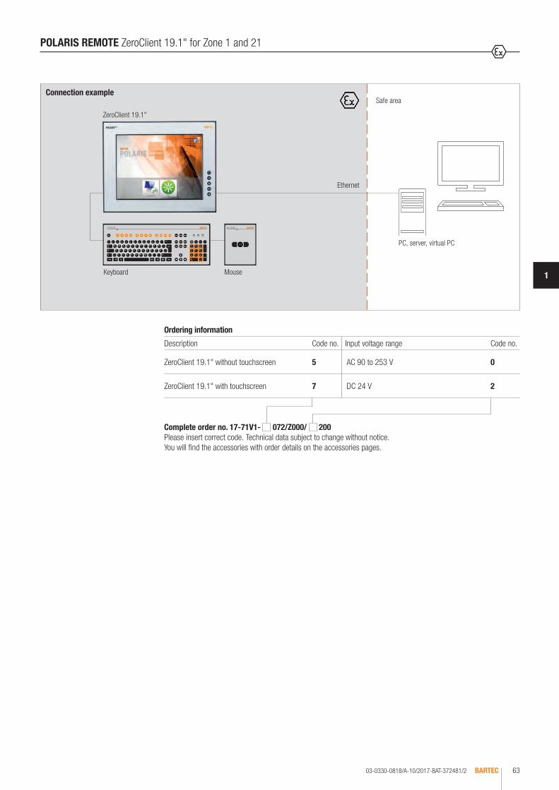
03-0330-0818/A-10/2017-BAT-372481/2 BARTEC 63
1
PC, server, virtual PC
ZeroClient 19.1"
Keyboard Mouse
Ethernet
POLARIS REMOTE ZeroClient 19.1" for Zone 1 and 21
Connection exampleSafe area
Ordering information
Description Code no. Input voltage range Code no.
ZeroClient 19.1" without touchscreen 5 AC 90 to 253 V 0
ZeroClient 19.1" with touchscreen 7 DC 24 V 2
Complete order no. 17-71V1- 072/Z000/ 200Please insert correct code. Technical data subject to change without notice. You will find the accessories with order details on the accessories pages.

03-0330-0816/A-10/2017-BAT-372474/1BARTEC64
The POLARIS ZeroClient series is the modern safe remote HMI series for the Zone 1 hazardous area. The connection is based on the RDP7 protocol to control a remote computer. The ZeroClient shell, developed by BARTEC itself, comes in a user-friendly tile look and was designed in conformance to today’s safety standards to prevent any risks emanating from the user or the network. The wired electrical connections are made via a terminal compartment in the “e” (increased safety) type of protection. State-of-the-art display technology provides optimum contrast even with a large viewing angle. The front-panel fitting assures easy installation. On request, the devices are also available as turn-key system solutions in stainless-steel enclosures as wall, floor or ceiling mounting versions. Intrinsically safe input devices can also be connected. The optional (intrinsically safe) touchscreen offers the ultimate in operating comfort.
POLARIS REMOTE ZeroClient 24" W for Zone 1 and 21
Technical data
Construction Front-panel fitting
Protection class IP 65 (front) IP 54 (back)
Display 24" W graphics-capable TFT colour display 16.7 million colours Full HD resolution, 1920 x 1080 pixels Brightness 300 cd/m2
Visible area approx. 531 x 299 mm Contrast 3000:1 Antireflection-coated glass pane Optional touchscreen (resistive)
Backlighting LED technology Service life approx. 50,000 hours (at +25 °C)
Interfaces 1 x Ex e Ethernet 100/10BaseT (optical fibres optional) 1 x Ex e USB 1 x Ex i USB 2 x Ex i PS/2 for intrinsically safe keyboard and mouse
Optional accessories Hand-held scanner on request
Dimensions (W x H x D) 644 mm x 406 mm x approx. 135 mm
Wall cut-out 630 mm x 392 mm + 0.5 mm
Weight approx. 40 kg
Power supply AC 90 to 253 V, 50 to 60 Hz DC 24 V ± 10 % on request
Max. power consumption Pmax. < 100 W depending on the variant
Admissible ambient temperature
Storage -20 °C to +50 °C Operation 0 °C to +50 °C System solution with heating on request.
Relative air humidity 5 to 95 % non-condensing
Vibration 0.7 g/1 mm; 5 Hz to 500 Hz pulse in all 3 axes
Shock 15 g/11 ms pulse in all 3 axes
Material Front: polyester foil on anodised aluminium plate (conditionally UV-resistant) Back: bichromated sheet steel
Explosion protection
Marking ATEX Zone 1 and 21
II 2G Ex db eb q [ib] IIC T4 Gb II 2D Ex tb IIIC T120 °C Db
Certification IBExU 05 ATEX 1117 X
Marking IECEx Ex db eb q [ib] IIC T4 Gb Ex tb IIIC T120 °C Db
Certification IECEx IBE 11.0007 X
Other approvals and certificates, see www.bartec.de
Variant for Zone 2 www.bartec.de

03-0330-0816/A-10/2017-BAT-372474/2 BARTEC 65
1
POLARIS REMOTE ZeroClient 24" W for Zone 1 and 21
PC, server, virtual PC
ZeroClient 24" W
Keyboard Mouse
Ethernet
Connection exampleSafe area
Ordering information
Description Code no. Input voltage range Code no.
ZeroClient 24" W without touchscreen C AC 90 to 253 V 0
ZeroClient 24" W with touchscreen D DC 24 V 2
Complete order no. 17-71V1- 072/Z000/ 200Please insert correct code. Technical data subject to change without notice. You will find the accessories with order details on the accessories pages.

03-0330-0552/A-10/2017-BAT-292153/1BARTEC66
The POLARIS II Remote 19.1" from BARTEC is a display which enables a PC to be operated in safe areas of hazardous areas. Distances of up to 300 m are possible. POLARIS II Remote 19.1" allows the user the possibility of utilising any currently available PC-based process control systems without restrictions in the Ex areas. The devices are also available for wall, floor or table mounting for optimum use. The screen on the POLARIS II Remote 19.1" is a TFT display with SXGA resolution and is characterised by its outstanding brilliance and a very large reading angle. A keyboard with integrated trackball or touchpad is available. The optional (intrinsically safe) touchscreen offers the ultimate in operating comfort. Linking in the safe area is established through a local unit (included in the scope of delivery).
POLARIS REMOTE POLARIS II Remote 19.1" for ATEX Zone 2 and ATEX Zone 21/22
Technical data
Construction Stainless-steel enclosure
Protection class IP 65
Display 19.1" graphics-capable TFT colour display 16.7 million colours SXGA resolution, 1280 x of 1024 pixels Brightness 300 cd/m² Visible surface approx. 376 x 301 mm Contrast 1300:1 Option of touchscreen (resistive)
Backlighting CFL technology Service life approx. 50,000 hours (at +25 °C)
Conductor length up to 300 m through STP cable VGA/PS2 up to 130 m through STP cable DVI/USB up to 500 m through multi-mode optical fibre cable DVI/USB up to 20 km through single-mode optical fibre cable DVI/USB
Dimensions (W x H x D) 610 mm x 450 mm x approx. 100 mm
Weight approx. 17 kg
Rated voltage AC 110 to 230 V, 47 to 63 Hz DC 24 V
Input voltage range AC 90 to 253 V DC 24 V ± 10 %
Max. power consumption Pmax. < 75 W
Permissible ambient temperatures
Storage -25 °C to +60 °C Operation 0 °C to +50 °C
Relative air humidity 5 to 95 % non-condensing
Material Stainless steel
Optional accessories Keyboard with integrated trackball 38 mm Keyboard with integrated trackball 50 mm Keyboard with integrated touchpad
Explosion protection
Marking ATEX Zone 2
II 3G Ex nA ic IIC T5 Gc -25 °C ≤ Ta ≤ +50 °C
Certification IBExU 09 ATEX 1113 X
Marking ATEX Zone 21/22
II 2D Ex ib tb IIIC T100 °C Db
Certification IBExU 09 ATEX 1113 X
Other approvals and certificates, see www.bartec.de

03-0330-0552/A-10/2017-BAT-292153/2 BARTEC 67
1
POLARIS REMOTE POLARIS II Remote 19.1" for ATEX Zone 2 and ATEX Zone 21/22
RJ 45 system
Video KeyboardMouse
PC
STP/S CAT.6/CAT.7 cable4 x 2 twisted pairLocal unit
Safe areaConnection example
Ordering information
Ex area Code no.
Version Code no.
Input voltage Code no.
Conductor length Code no.
Keyboard language
Code no.
Insert unit Code no.
Zone 21/22 1
POLARIS II Remote 19.1" without touchscreen
6 AC 90 to 253 V 1
up to 300 m through STP cable VGA/PS2
0German 1 Trackball
50 mm1
up to 130 m through STP cable DVI/USB
4
English 2 Trackball 38 mm
2
Zone 2 2
POLARIS II Remote 19.1" with touchscreen
5 DC 24 V 2
up to 500 m through multi-mode fibre- optic cable DVI/USB
5
French 3 Touchpad 4up to 20 km through single-mode optical fibre cable DVI/USB
6
Complete order no. 17-7 V5- 0 / 00 Please insert correct code. Technical data subject to change without notice. Other versions on request.

03-0330-0553/A-10/2017-BAT-292154/1BARTEC68
The POLARIS II Remote 22" W from BARTEC is a display which enables a PC to be operated in safe areas of hazardous areas. Distances of up to 200 m are possible. POLARIS II Remote 22" W allows the user the possibility of utilising any currently available PC-based process control systems without restrictions in the Ex areas. The devices are also available for wall, floor or table mounting for optimum use. The POLARIS II Remote 22" W screen is a TFT display with WSXGA+ resolution and is distinguished by its outstanding brilliance and a very large reading angle. A keyboard with integrated trackball or touchpad is available. The optional (intrin-sically safe) touchscreen offers the ultimate in operating comfort. Linking in the safe area is established through a local unit (included in the scope of delivery).
POLARIS REMOTE POLARIS II Remote 22" W for ATEX Zone 2 and ATEX Zone 21/22
Technical data
Construction Stainless-steel enclosure
Protection class IP 65
Display 22" W graphics-capable TFT colour display 16.7 million colours WSXGA+ resolution, 1680 x 1050 pixels Brightness 300 cd/m² Visible surface approx. 474 x 296 mm Contrast 600:1 Optional touchscreen (resistive)
Backlighting CFL technology Service life approx. 50,000 hours (at +25 °C)
Conductor length up to 200 m through STP cable VGA/PS2 up to 130 m through STP cable DVI/USB up to 500 m through multi-mode optical fibre cable DVI/USB up to 20 km through single-mode optical fibre cable DVI/USB
Dimensions (W x H x D) 610 mm x 450 mm x approx. 100 mm
Weight approx. 17 kg
Rated voltage AC 110 to 230 V, 47 to 63 Hz DC 24 V
Input voltage range AC 90 to 253 V DC 24 V ± 10 %
Max. power consumption Pmax. < 75 W
Permissible ambient temperatures
Storage -25 °C to +60 °C Operation 0 °C to +50 °C
Relative air humidity 5 to 95 % non-condensing
Material Stainless steel
Optional accessories Keyboard with integrated trackball 38 mm Keyboard with integrated trackball 50 mm Keyboard with integrated touchpad
Explosion protection
Marking ATEX Zone 2
II 3G Ex nA ic IIC T5 Gc -25 °C ≤ Ta ≤ +50 °C
Certification IBExU 09 ATEX 1113 X
Marking ATEX Zone 21/22
II 2D Ex ib tb IIIC T100 °C Db
Certification IBExU 09 ATEX 1113 X
Other approvals and certificates, see www.bartec.de

03-0330-0553/A-10/2017-BAT-292154/2 BARTEC 69
1
POLARIS REMOTE POLARIS II Remote 22" W for ATEX Zone 2 and ATEX Zone 21/22
RJ 45 system
Video KeyboardMouse
PC
STP/S CAT.6/CAT.7 cable4 x 2 twisted pairLocal unit
Safe areaConnection example
Ordering information
Ex area Code no.
Version Code no.
Input voltage Code no.
Conductor length Code no.
Keyboard language
Code no.
Insert unit Code no.
Zone 21/22 1
POLARIS II Remote 22" W without touchscreen
4 AC 90 to 253 V 1
up to 200 m through STP cable VGA/PS2
0German 1 Trackball
50 mm1
up to 130 m through STP cable DVI/USB
4
English 2 Trackball 38 mm
2
Zone 2 2
POLARIS II Remote 22" W with touchscreen
3 DC 24 V 2
up to 500 m through multi-mode optical fibre cable DVI/USB
5
French 3 Touchpad 4up to 20 km through single-mode optical fibre cable DVI/USB
6
Complete order no. 17-7 V5- 0 / 00 Please insert correct code. Technical data subject to change without notice. Other versions on request.

03-0330-0792/A-10/2017-BAT-365387/1BARTEC70
The POLARIS II Remote 24" W from BARTEC is a display which enables a PC to be operated in safe areas of hazardous areas. Distances of up to 20 km are possible. POLARIS II Remote 24" W allows the user the possibility of utilising any currently available PC-based process control systems without restrictions in the Ex areas. The devices are also available for wall, floor or table mounting for optimum use. The POLARIS II Remote 24" W screen is a TFT display with Full HD resolution and is distinguished by its outstanding brilliance and a very large reading angle. A keyboard with integrated trackball or touchpad is avail-able. The optional (intrinsically safe) touchscreen offers the ultimate in operating comfort. Linking in the safe area is established through a local unit (included in the scope of delivery).
POLARIS REMOTE POLARIS II Remote 24" W for ATEX Zone 2 and ATEX Zone 21/22
Technical data
Construction Stainless-steel enclosure
Protection class IP 65
Display 24" W graphics-capable TFT colour display 16.7 million colours Full HD resolution, 1920 x 1080 pixels Brightness 300 cd/m² Visible surface approx. 474 x 296 mm Contrast 5000:1 Optional touchscreen (resistive)
Backlighting LED technology Service life approx. 50,000 hours (at +25 °C)
Conductor length up to 130 m through STP cable DVI/USB up to 500 m through multi-mode optical fibre cable DVI/USB up to 20 km through single-mode optical fibre cable DVI/USB
Dimensions (W x H x D) 670 mm x 450 mm x approx. 100 mm
Weight approx. 19 kg
Rated voltage AC 110 to 230 V, 47 to 63 Hz DC 24 V
Input voltage range AC 90 to 253 V DC 24 V ± 10 %
Max. power consumption Pmax. < 75 W
Permissible ambient temperatures
Storage -25 °C to +60 °C Operation 0 °C to +50 °C
Relative air humidity 5 to 95 % non-condensing
Material Stainless steel
Optional accessories Keyboard with integrated trackball 38 mm Keyboard with integrated trackball 50 mm Keyboard with integrated touchpad
Explosion protection
Marking ATEX Zone 2
II 3G Ex nA ic IIC T5 Gc -25 °C ≤ Ta ≤ +50 °C
Certification IBExU 09 ATEX 1113 X
Marking ATEX Zone 21/22
II 2D Ex ib tb IIIC T100 °C Db
Certification IBExU 09 ATEX 1113 X
Other approvals and certificates, see www.bartec.de

03-0330-0792/A-10/2017-BAT-365387/2 BARTEC 71
1
Connection example
RJ 45 system
PC
Video KeyboardMouse
STP/S CAT.6/CAT.7 cable4 x 2 twisted pair
Safe area
Local unit
Ordering information
Ex area Code no.
Input voltage Code no.
Zone 21/22 1 AC 90 to 253 V 1
Zone 2 2 DC 24 V 2
Complete order no. 17-7 V5-8 0 / 00 Please insert correct code. Technical data subject to change without notice. Other versions on request .
Conductor length Code no.
Keyboard language Code no.
Insert unit Code no.
up to 130 m through STP cable DVI/USB
4 German 1Trackball 50 mm
1
up to 500 m through Optical fibres Multi Mode DVI/USB
5 English 2Trackball 38 mm
2
up to 20 km through Optical fibres Single Mode DVI/USB
6 French 3 Touchpad 4
POLARIS REMOTE POLARIS II Remote 24" W for ATEX Zone 2 and ATEX Zone 21/22

03-0330-0407/A-10/2017-BAT-242769BARTEC72
Dimensions and wall cut-out for keyboard (in mm)
all hole diameters: 3.3 mm
400300100
390
420
85150
140
3.3
170
Dimensions (in mm)
H80°
223.4
T
B
R 15
The intrinsically safe keyboard and the mouse variants are intended for POLARIS Professional and POLARIS Remote for zone 1 and 2 and for zone 21 and 22. They are connected directly to the POLARIS Panel PC or POLARIS Remote. The chemically resistant polyester foil is easy to clean and resistant to many aggressive fluids. The keyboard is available in various languages.
POLARIS REMOTE Keyboard
Technical data
Construction Front-panel fitting
Protection class IP 65
Material Polyester foil on aluminium sheet (conditionally UV-resistant)
Dimensions (W x H) 420 mm x 170 mm
Wall cut-out 390 mm x 140 mm
Installation depth 18 mm
Weight approx. 700 g
Technical data
Material Stainless steel 1.4301; AISI 304
Dimensions (W x H x D) 600 mm x 85 mm x 220 mm
Protection class IP 65
Explosion protection
Marking ATEX II 2G Ex ib IIC T4 Gb II 2D Ex ib IIIC T120°C Db
Certification IBExU 05 ATEX 1117 X
Marking IECEx Ex ib IIC T4 GbEx ib IIIC T120 °C Db
Certification IECEx IBE 11.0007 X
Other approvals and certificates, see www.bartec.de
Ordering information
Enclosure 05-0041-0277
Complete solution with installed equipment on request.Technical data subject to change without notice.
Ordering information
Language Order no.
German 17-71VZ-4010
English 17-71VZ-4020
French 17-71VZ-4030
Other languages on request. Technical data subject to change without notice.

03-0330-0445/A-10/2017-BAT-242770 BARTEC 73
1
all hole diameters: 3.3 mm
Dimensions and wall cut-out (mm)
130
170
100
110
150
85 140
3.3
POLARIS REMOTE Mouse, Trackball, Joystick and Touchpad
POLARIS Mouse, Trackball, Joystick and Touchpad
Explosion protection
Marking ATEX II 2G Ex ib IIC T4 Gb II 2D Ex ib IIIC T120 °C Db
Certification IBExU 05 ATEX 1117 X
Marking IECEx Ex ib IIC T4 Gb Ex ib IIIC T120 °C Db
Certification IECEx IBE 11.0007 X
Other approvals and certificates, see www.bartec.de
POLARIS Touchpad
Technical data
Construction Capacitive touchpad for Front-panel fitting
Protection class IP 65
Material Polyester foil on aluminium sheet (conditionally UV-resistant)
Dimensions (W x H)
130 mm x 170 mm
Wall cut-out 100 mm x 140 mm
Installation depth 15 mm
Weight approx. 250 g
Ordering information
Description Order no.
Mouse 17-71VZ-1000
Trackball 17-71VZ-2000
Touchpad 17-71VZ-3000
Joystick with button 17-71VZ-9000
Technical data subject to change without notice.
POLARIS Mouse
Technical data
Construction Front-panel fitting
Protection class IP 65
Material Polyester foil on aluminium sheet (conditionally UV-resistant)
Dimensions (W x H)
130 mm x 170 mm
Wall cut-out 100 mm x 140 mm
Installation depth 15 mm
Weight approx. 270 g
POLARIS Trackball/Joystick
Technical data
Construction Front-panel fitting
Protection class Trackball (front side) static IP 65dynamic IP 56
Joystick IP 65
Material Polyester foil on aluminium sheet (conditionally UV-resistant)
Dimensions (W x H)
130 mm x 140 mm
Wall cut-out 100 mm x 140 mm
Installation depth 43 mm
Weight approx. 500 g

03-0330-0659/A-08/2014-BAT-318904/1BARTEC74
POLARIS REMOTE Accessories
Ordering information
Illustration Description Order no.
Connection cable for keyboard and mouse variants
Keyboard and mouse 1.8 m 05-0068-0163
Keyboard and mous 3.0 m 05-0068-0204
Keyboard and trackball/joystick 1.8 m 05-0068-0172
Keyboard and trackball/joystick 3.0 m 05-0068-0205
Keyboard and touchpad 1.8 m 05-0068-0183
Keyboard and touchpad 3.0 m 05-0068-0206
Reinforcement frame
POLARIS series 15" 05-0205-0009
POLARIS series 19,1" 05-0205-0010
POLARIS series 24" 05-0205-0012
Mounting clamp set
4 pieces 05-0091-0111
6 pieces 05-0091-0112
LAN STP cable
CAT.7 4 x 2 x 23 AWG, outer diameter: 7.9 mm 02-4082-0002
CAT.7 4 x 2 x 22 AWG, outer diameter: 18 mm; armoured 02-4082-0004
Note: additional cable glands are necessary for armouring.
Power pack for local unit
for CAT cable with keyboard usage 03-9911-0018
for CAT cable without keyboard usage 03-9911-0020
for optical fibre cable on request
19" rack mounting set for local unit
for CAT cable 03-8931-0037
for optical fibre cable 03-8931-0038

03-0330-0659/A-08/2014-BAT-318904/2 BARTEC 75
1
Ordering information
Illustration Description Order no.
USB to PS/2 adapter for mouse and keyboard, for non-hazardous areas 03-9829-0007
Local unit/STP cable (UAA/PS2)
“Black Box“ make with RS232 interface 03-9840-0091
“IHSE“ make with RS232 interface 03-9840-0079
KVM cable
VGA, PS/2 keyboard, PS/2 mouse, lengths 3 m 05-0068-0218
VGA, AT keyboard, serial mouse, lengths 3 m 05-0068-0220
Original packaging
POLARIS series 15" 04-9035-0007
POLARIS series 19.1" 04-9035-0008
Ordering information
Illustration Description Dimensions in mm Order no.
Standard Stainless-steel enclosure
Technical data
Material Stainless-steel 1.4404; AISI 316 L
Surface brushed
Protection class IP 65
• with adapter connection without stand (B x H x T)
POLARIS series 15" 650 x 500 x 150 05-0041-0395
POLARIS series 19.1" 760 x 600 x 150 05-0041-0994
POLARIS series 24" W 885 x 625 x 150 05-0041-0993
POLARIS REMOTE Accessories

03-0330-0659/A-08/2014-BAT-318904/3BARTEC76
B
H 120°
T
B
H
T
POLARIS REMOTE Accessories
Ordering information
Illustration Description Dimensions in mm Order no.
Exclusive II Stainless-steel enclosure
Technical data
Material Stainless-steel grade 1.4301
• with adapter connection (B x H x T)
POLARIS series 15" 650 x 578 x 543 05-0041-0354
POLARIS series 19.1" 650 x 598 x 543 05-0041-0353
POLARIS series 24" W 885 x 625 x 543 05-0041-0406
• Stainless-steel enclosure - swivel/tilt • without desktop mount
(B x H x T)
POLARIS series 15" 770 x 685 x 218 05-0041-0356
POLARIS series 19.1" 770 x 685 x 218 05-0041-0355

03-0330-0659/A-08/2014-BAT-318904/4 BARTEC 77
1
POLARIS REMOTE Accessories
Ordering information
Illustration Description Order no.
Stand for floor mounting for Exclusive II Stainless-steel enclosure 05-0005-0050
• Material: stainless-steel grade 1.4301 • Swivel • Height approx. 900 mm, diameter 80 mm
Stand for floor mounting for Standard Stainless-steel enclosure from 15" series and POLARIS II
05-0005-0078
• Material: stainless-steel grade 1.4301 • Swivel • Height approx. 1000 mm, diameter 80 mm
Desktop mount for Stainless-steel enclosure for POLARIS 15" series/19.1" series 05-0005-0070
• Material: stainless-steel grade 1.4301 • Swivel • Height approx. 140 mm, diameter 80 mm
Support arm for wall mounting 05-0005-0058
• Material: stainless-steel grade 1.4301 • Swivel • Length approx. 580 mm
Stainless-steel enclosure with additional fitted components on request
Material: stainless-steel • Suitable for all POLARIS devices • Optional for fitting switch modules and/or heating • For wall mounting with mounting straps or support arm or for floor mounting with stand

03-0330-0608/A-10/2017-BAT-307295/1BARTEC78
The POLARIS Touch Panel 5.7" is an innovative further development of the POLARIS Panel PCs 5.7". High-resolution displays with LED technology and touchscreen for intuitive as well as comfortable operation are available now in the standard variant. State-of-the-art LED display technology ensures the optimum contrast even with a large viewing angle. The proven LX800 offers sufficient computer capacity for presenting HTML pages or functioning as a remote client.Of course, here too the user can work with the latest “BMS-Graf-pro” Runtime 7 under Windows® XP Embedded, for example for the transmission of projects over the Ethernet, the use of graphics lists or an integrated user administration.Allows a high-performance visual display and operation of the processes directly on site. The front-panel fitting makes mounting easy. On request, the devices are also available as turn-key system solutions in a Stainless-steel enclosure for wall or floor mounting. An intrinsically safe USB interface is available for a USB Ex i memory stick. Intrinsically safe input devices can also be connected.
POLARIS COMFORT POLARIS Touch Panel 5.7"
Technical data
Construction Front-panel fitting
Protection class IP 65 (front) IP 54 (back)
Display 5.7” TFT graphic display 262,144 colours Resolution VGA 640 x 480 pixels Brightness 700 cd/m² Visible surface approx. 115 x 86 mm Contrast 800:1 Touchscreen (resistive)
Backlighting LED technology Service life approx. 50,000 hours (at +25 °C)
Computer capacity LX800 processor, 500 MHz Compact Flash 4 GB
Operating system Windows® XP Embedded (pre-installed)
Interfaces (basic version)
1 x Ex e Ethernet 100/10BaseT 1 x Ex e RS422 1 x Ex i USB for Ex i memory stick 1 x Ex i PS/2 for intrinsically safe mouse
Keyboard (short-stroke keys)
alphanumeric key block 4 cursor keys 6 special keys 10 function keys able to be labelled with LEDs
Dimensions (W x H x D) 335 mm x 199 mm x approx. 130 mm
Wall cut-out 321 mm x 179 mm + 0.5 mm
Weight approx. 10 kg
Power supply DC 24 V ± 10 %
Max. power consumption Pmax.< 30 W
Permissible ambient temperatures
Storage -20 °C to +50 °C Operation 0 °C to +50 °CVariant: Operation -20 °C to +50 °C on request (without external heating)
Relative air humidity 5 to 95 % non-condensing
Vibration 0.7 g/1 mm; 5 Hz to 500 Hz pulse in all 3 axes
Shock 15 g/11 ms pulse in all 3 axes
Material Front: polyester foil on anodised aluminium plate (conditionally UV-resistant) Back: bichromated sheet steel
Explosion protection
Marking ATEX Zone 1 and 21
II 2G Ex db eb q [ib] IIC T4 Gb II 2D Ex tb IIIC T120 °C Db
Certification IBExU 05 ATEX 1117 X
Marking IECEx Ex db eb q [ib] IIC T4 Gb Ex tb IIIC T120 °C Db
Certification IECEx IBE 11.0007 X
Other approvals and certificates, see www.bartec.de
Variant for Zone 2 www.bartec.de

03-0330-0608/A-10/2017-BAT-307295/2 BARTEC 79
1
Safe areaConnection example
PLC
Mouse
Touch Panel 5.7“Power supply
e. g. RS422 or PROFIBUS-DP
e. g. connection to the control system, HTML server or remote server
Ethernet
POLARIS COMFORT POLARIS Touch Panel 5.7"
Ordering information
Description Interfaces Code no.
Touch Panel 5.7"
USB Ex e/RS422 (recommended version) 37
RS485 38
BARTEC PROFIBUS-DP 02
RS232 09
TTY 11
BARTEC PROFIBUS-DP, Ex d-USB 33
Further Interface combinations on request XX
Complete order no. 17-71V1-A0 /X000Please insert correct code. Technical data subject to change without notice. You will find the accessories with order details on the accessories pages.

03-0330-0609/A-10/2017-BAT-307296/1BARTEC80
The POLARIS Touch Panel 10.4" is an innovative further development of the POLARIS Panel PCs 10.4". High-resolution displays with LED technology and touchscreen for intuitive as well as comfortable operation are available now in the standard variant. State-of-the-art LED display technology ensures the optimum contrast even with a large viewing angle. The proven LX800 offers sufficient computer capacity for presenting HTML pages or functioning as a remote client. Of course, here too the user can work with the latest “BMS-Graf-pro” Runtime 7 under Windows® XP Embedded, for example for the transmission of projects over the Ethernet, the use of graphics lists or an integrated user administration. Allows a high-performance visual display and operation of the processes directly on site. The front-panel fitting makes mounting easy. On request, the devices are also available as turn-key system solutions in a Stainless-steel enclosure for wall or floor mounting. An intrinsically safe USB interface is available for a USB Ex i memory stick. Intrinsically safe input devices can also be connected.
POLARIS COMFORT POLARIS Touch Panel 10.4"
Technical data
Construction Front-panel fitting
Protection class IP 65 (front) IP 54 (back)
Display 10.4" TFT graphic display 262,144 colours Resolution SVGA 800 x 600 pixels Brightness 400 cd/m² Visible surface approx. 211 x 158 mm Contrast 700:1 Touchscreen (resistive)
Backlighting LED technology Service life approx. 50,000 hours (at +25 °C)
Computer capacity LX800 processor, 500 MHz Compact Flash 4 GB
Operating system Windows® XP Embedded (pre-installed)
Interfaces (basic version)
1 x Ex e Ethernet 100/10BaseT 1 x Ex e RS422 1 x Ex i USB for Ex i memory stick 1 x Ex i PS/2 for intrinsically safe mouse
Keyboard (short-stroke keys)
Alphanumeric key block 4 cursor keys 10 special keys12 function keys able to be labelled with LEDs
Optional accessories Hand-held scanner on request
Abmessungen (W x H x D) 400 mm x 246 mm x approx. 130 mm
Wall cut-out 386 mm x 226 mm + 0.5 mm
Weight approx. 14 kg
Power supply DC 24 V ± 10 %
Max. power consumption Pmax.< 30 W
Permissible ambient temperatures
Storage -20 °C to +50 °C Operation 0 °C to +50 °CVariant Operation -20 °C to +50 °C on request (without external heating)
Relative air humidity 5 to 95 % non-condensing
Vibration 0.7 g/1 mm; 5 Hz to 500 Hz pulse in all 3 axes
Shock 15 g/11 ms pulse in all 3 axes
Material Front: polyester foil on anodised aluminium plate (conditionally UV-resistant) Back: bichromated sheet steel
Explosion protection
Marking ATEX Zone 1 and 21
II 2G Ex db eb q [ib] IIC T4 Gb II 2D Ex tb IIIC T120 °C Db
Certification IBExU 05 ATEX 1117 X
Marking IECEx Ex db eb q [ib] IIC T4 Gb Ex tb IIIC T120 °C Db
Certification IECEx IBE 11.0007 X
Other approvals and certificates, see www.bartec.de
Variant for Zone 2 www.bartec.deOptionales Zubehör Handscanner auf Anfrage
Optional accessories Hand-held scanner on request

03-0330-0609/A-10/2017-BAT-307296/2 BARTEC 81
1
Safe areaConnection example
Mouse
Touch Panel 10.4"Power supply
e. g. RS422 or PROFIBUS-DP
e. g. connection to the control system, HTML server or remote server
Ethernet
POLARIS COMFORT POLARIS Touch Panel 10.4"
PLC
Complete order no. 17-71V1-90 /X000Please insert correct code. Technical data subject to change without notice. You will find the accessories with order details on the accessories pages.
Ordering information
Description Interfaces Code no.
Touch Panel 10.4"
USB Ex e/RS422 (recommended version) 37
RS485 38
BARTEC PROFIBUS-DP 02
RS232 09
TTY 11
BARTEC PROFIBUS-DP, Ex d-USB 33
Further Interface combinations on request XX
Hand-held scanner BCS 3678ex
Ex e USB

03-0330-0610/A-10/2017-BAT-307297/1BARTEC82
The POLARIS Touch Panel 12.1" is an innovative further development of the POLARIS Panel PCs 12.1". High-resolution displays with LED technology and touchscreen for intuitive as well as comfortable operation are available now in the standard variant. State-of-the-art LED display technology ensures the optimum contrast even with a large viewing angle. The proven LX800 offers sufficient computer capacity for presenting HTML pages or functioning as a remote client.Of course, here too the user can work with the latest “BMS-Graf-pro” Runtime 7 under Windows® XP Embedded, for example for the transmission of projects over the Ethernet, the use of graphics lists or an integrated user administration.The front-panel fitting makes mounting easy. On request, the devices are also available as turn-key system solutions in a Stainless-steel enclosure for wall or floor mounting. An intrinsically safe USB interface is available for a USB Ex i memory stick. Intrinsically safe input devices can also be connected.
POLARIS COMFORT POLARIS Touch Panel 12.1"
Technical data
Construction Front-panel fitting
Protection class IP 65 (front) IP 54 (back)
Display 12.1" TFT graphic display 262,144 colours Resolution XGA 1024 x 768 pixels Brightness 500 cd/m² Visible surface approx. 246 x 184 mm Contrast 700:1 Touchscreen (resistive)
Backlighting LED technology Service life approx. 50,000 hours (at +25 °C)
Computer capacity LX800 processor, 500 MHz Compact Flash 4 GB
Operating system Windows® XP Embedded (pre-installed)
Interfaces (basic version)
1 x Ex e Ethernet 100/10BaseT (optical fibres optional) 1 x Ex e RS422 1 x Ex i USB for Ex i memory stick 1 x Ex i PS/2 for intrinsically safe mouse
Keyboard (short-stroke keys)
Alphanumeric key block 4 cursor keys 12 cursor keys 16 function keys able to be labelled with LEDs
Optional accessories Hand-held scanner on request
Dimensions (W x H x D) 440 mm x 275 mm x approx. 130 mm
Wall cut-out 425 mm x 255 mm + 0.5 mm
Weight approx. 18 kg
Power supply DC 24 V ± 10 %
Max. power consumption Pmax.< 35 W
Permissible ambient temperatures
Storage -20 °C to +50 °C Operation 0 °C to +50 °C
Variant: Operation -20 °C to +50 °C on request (without external heating)
Relative air humidity 5 to 95 % non-condensing
Vibration 0.7 g/1 mm; 5 Hz to 500 Hz pulse in all 3 axes
Shock 15 g/11 ms pulse in all 3 axes
Material Front: polyester foil on anodised aluminium plate (conditionally UV-resistant) Back: bichromated sheet steel
Explosion protection
Marking ATEX Zone 1 and 21
II 2G Ex db eb qb [ib op pr] IIC T4 II 2D Ex tb IIIC T120 °C
Certification IBExU 05 ATEX 1117 X
Marking IECEx Ex db eb qb [ib op pr] IIC T4 Ex tb IIIC T120 °C
Certification IECEx IBE 11.0007 X
Other approvals and certificates, see www.bartec.de
Variant for Zone 2 www.bartec.de
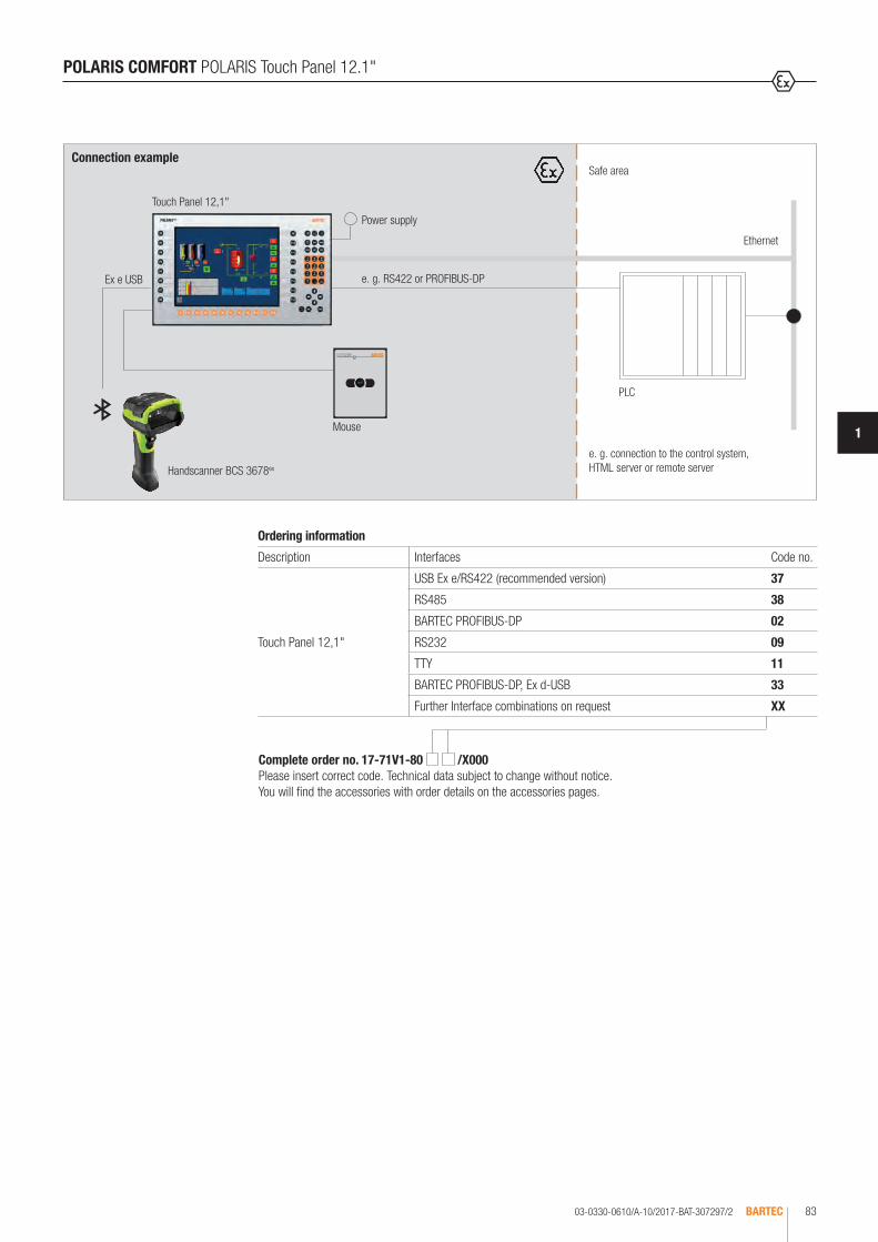
03-0330-0610/A-10/2017-BAT-307297/2 BARTEC 83
1
Safe areaConnection example
PLC
Mouse
Touch Panel 12,1"
Power supply
e. g. RS422 or PROFIBUS-DP
e. g. connection to the control system, HTML server or remote server
Ethernet
POLARIS COMFORT POLARIS Touch Panel 12.1"
Handscanner BCS 3678ex
Complete order no. 17-71V1-80 /X000Please insert correct code. Technical data subject to change without notice. You will find the accessories with order details on the accessories pages.
Ordering information
Description Interfaces Code no.
Touch Panel 12,1"
USB Ex e/RS422 (recommended version) 37
RS485 38
BARTEC PROFIBUS-DP 02
RS232 09
TTY 11
BARTEC PROFIBUS-DP, Ex d-USB 33
Further Interface combinations on request XX
Ex e USB

03-0330-0613/A-10/2017-BAT-307306BARTEC84
The BMS-Graf-pro programming package enables a simple and comfortable creation of process visualisation for POLARIS Comfort and POLARIS Professional. Alarm signals, operating messages, variables, user administration, text lists, and graphics lists can be generated in one project for animation and process images. With the aid of high-performance objects, from the line to touch buttons, the process images can be conveniently produced on a user friendly interface. The BMS-Graf-pro Runtime is optimised to the quickest reaction times. This benefits the presentation of the process images and also the communication for control. Communication protocols such as Modbus/TCP also support this optimisation. In the course of the development, particular attention was paid to ensuring that an existing project from older BMS Graf and BMS-Graf-pro versions could be opened easily and if necessary transferred into the new device with very little adjustments required.
Ordering information
Visualisation Software BMS-Graf-pro 7 for all available languages
17-28TF-0075
Technical data subject to change without notice.
Technical data
Technical characteristic figures
Images 500 Fields per image 100 Variables per image 100
Graphics objects Curves 50 Graphics lists over 100 Text lists over 100
Variables over 1000 Messages 250 Message text 250 Size of message buffer 2000
User administration User levels 25
Communication PROFIBUS DP Modbus/TCP Client Modbus RTU Master Modbus RTU Slave
System requirements Windows® XP or higher Processor at least 2 GHz Graphics at least XGA
POLARIS requirements Windows® XP Embedded or higher Processor at least 500 MHz Graphics at least VGA
POLARIS COMFORT Visualisation Software BMS-Graf-pro 7
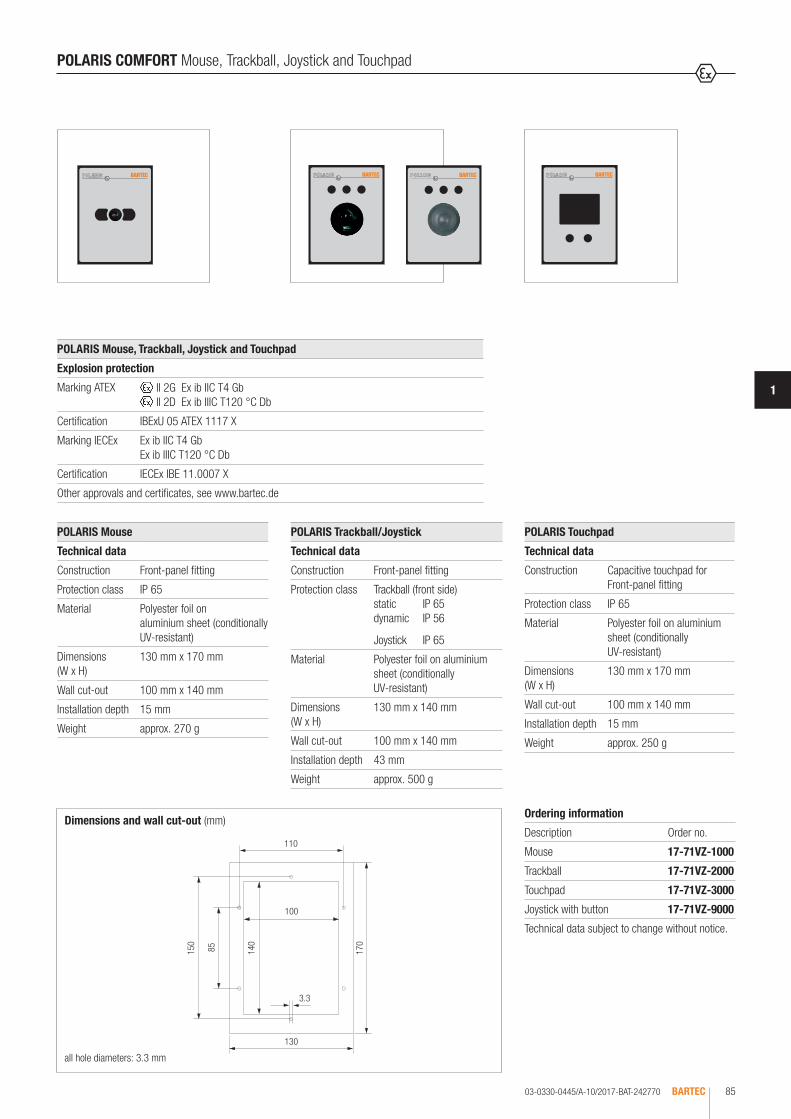
03-0330-0445/A-10/2017-BAT-242770 BARTEC 85
1
all hole diameters: 3.3 mm
Dimensions and wall cut-out (mm)
130
170
100
110
150
85 140
3.3
POLARIS COMFORT Mouse, Trackball, Joystick and Touchpad
POLARIS Mouse, Trackball, Joystick and Touchpad
Explosion protection
Marking ATEX II 2G Ex ib IIC T4 Gb II 2D Ex ib IIIC T120 °C Db
Certification IBExU 05 ATEX 1117 X
Marking IECEx Ex ib IIC T4 Gb Ex ib IIIC T120 °C Db
Certification IECEx IBE 11.0007 X
Other approvals and certificates, see www.bartec.de
POLARIS Touchpad
Technical data
Construction Capacitive touchpad for Front-panel fitting
Protection class IP 65
Material Polyester foil on aluminium sheet (conditionally UV-resistant)
Dimensions (W x H)
130 mm x 170 mm
Wall cut-out 100 mm x 140 mm
Installation depth 15 mm
Weight approx. 250 g
Ordering information
Description Order no.
Mouse 17-71VZ-1000
Trackball 17-71VZ-2000
Touchpad 17-71VZ-3000
Joystick with button 17-71VZ-9000
Technical data subject to change without notice.
POLARIS Mouse
Technical data
Construction Front-panel fitting
Protection class IP 65
Material Polyester foil on aluminium sheet (conditionally UV-resistant)
Dimensions (W x H)
130 mm x 170 mm
Wall cut-out 100 mm x 140 mm
Installation depth 15 mm
Weight approx. 270 g
POLARIS Trackball/Joystick
Technical data
Construction Front-panel fitting
Protection class Trackball (front side) static IP 65dynamic IP 56
Joystick IP 65
Material Polyester foil on aluminium sheet (conditionally UV-resistant)
Dimensions (W x H)
130 mm x 140 mm
Wall cut-out 100 mm x 140 mm
Installation depth 43 mm
Weight approx. 500 g

03-0330-0660/A-10/2017-BAT-318915/1BARTEC86
POLARIS COMFORT Accessories
Ordering information
Illustration Description Order no.
Ex i USB Stick ATEX/IECEx Zone 1 and Zone 21
Ex i memory stick 4 GB 17-71VZ-5000/0100
Recovery stick Built 008 17-71VZ-5000/0108
Reinforcement frame
Touch Panel 5.7" 05-0205-0006
Touch Panel 10.4" 05-0205-0008
Touch Panel 12.1" 05-0205-0007
Mounting clamps set
4 pieces 05-0091-0111
6 pieces 05-0091-0112
LAN STP cable
CAT.7 4 x 2 x 23 AWG, outer diameter: 7.9 mm 02-4082-0002
CAT.7 4 x 2 x 22 AWG, outer diameter: 18 mm; armoured 02-4082-0004
Note: Additional cable glands for armouring necessary
Original packing
Touch Panel 5.7" 04-9035-0004
Touch Panel 10.4" 04-9035-0005
Touch Panel 12.1" 04-9035-0006
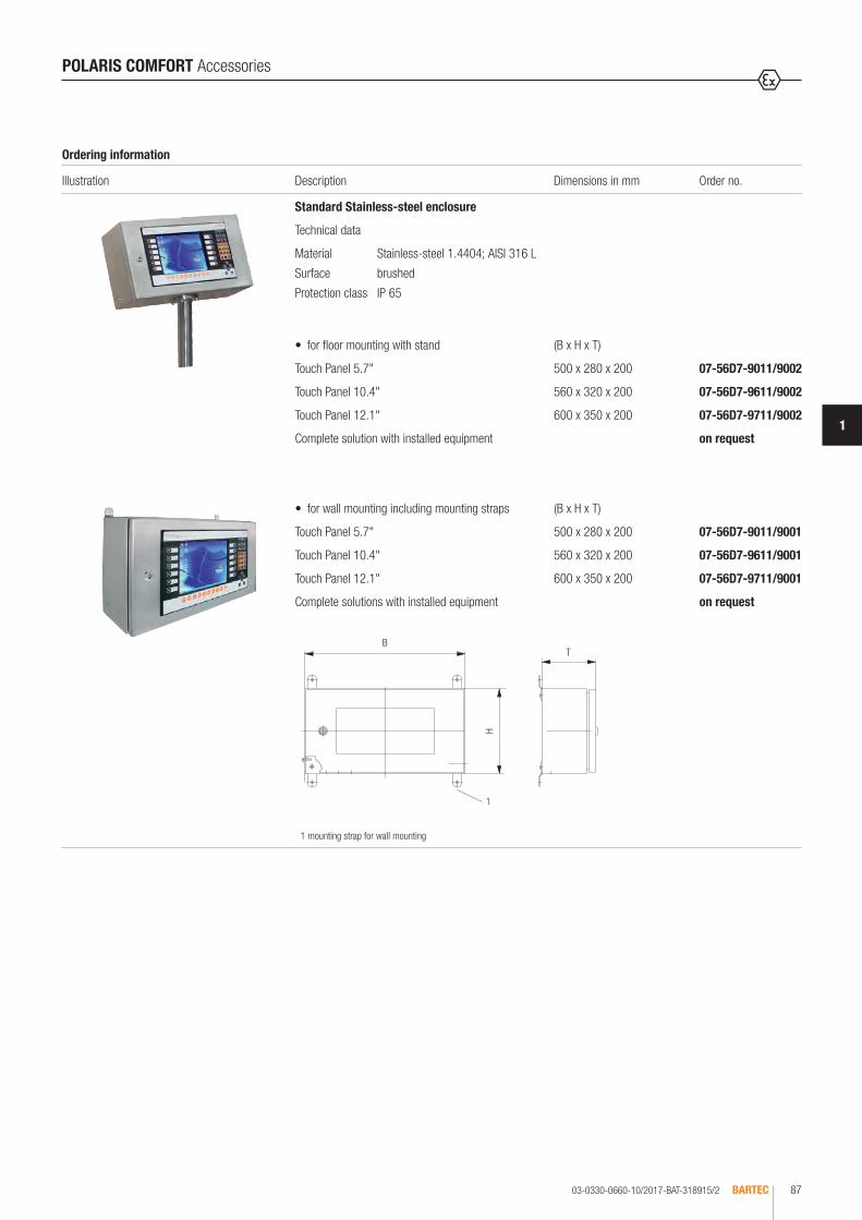
03-0330-0660-10/2017-BAT-318915/2 BARTEC 87
1
B
H
T
1
Ordering information
Illustration Description Dimensions in mm Order no.
Standard Stainless-steel enclosure
Technical data
Material Stainless-steel 1.4404; AISI 316 L
Surface brushed
Protection class IP 65
• for floor mounting with stand (B x H x T)
Touch Panel 5.7" 500 x 280 x 200 07-56D7-9011/9002
Touch Panel 10.4" 560 x 320 x 200 07-56D7-9611/9002
Touch Panel 12.1" 600 x 350 x 200 07-56D7-9711/9002
Complete solution with installed equipment on request
• for wall mounting including mounting straps (B x H x T)
Touch Panel 5.7" 500 x 280 x 200 07-56D7-9011/9001
Touch Panel 10.4" 560 x 320 x 200 07-56D7-9611/9001
Touch Panel 12.1" 600 x 350 x 200 07-56D7-9711/9001
Complete solutions with installed equipment on request
POLARIS COMFORT Accessories
1 mounting strap for wall mounting

03-0330-0406/A-10/2017-BAT-236278/1BARTEC88
The POLARIS Control is the ideal solution for all simple applications requiring texts and small-scale graphics. For the display, an extremely conveniently readable daylight blue-colour display is utilised. With the Control, process visualisation can be directly connected in explosive areas without the need for additional intrinsically safe isolation cards. There is no need to lay blues lines for intrinsically safe circuits. A separate wiring of the data line is not neces-sary. The POLARIS Control can be directly connected to the PROFIBUS-DP or the communication interface of the control station. RS422/RS485 or PROFI-BUS-DP are available, for example. An intrinsically safe USB interface for a USB Ex i memory stick enables the device configuration to be transferred easily. On request, the devices are also available as turn-key system solutions in a Stainless-steel enclosure for wall or floor mounting. The visualisation is created with the “BMS-Graf- pro“ programming package (Version 6.xxx), which has been specially developed and optimised for this purpose.
POLARIS BASIC POLARIS Control
Technical data
Construction Front-panel fitting
Protection class IP 65 (front) IP 54 (back)
Display LCD display 2 colours white/blue 240 x 64 pixels Visible area approx. 133 x 40 mm Antireflection-coated glass pane Daylight display technology
Backlighting LED technology
Keyboard (short-stroke keys)
Alphanumeric key block 4 special keys 12 function keys able to be labelled with LEDs
Interfaces (Basic version)
1 x Ex i USB for Ex i memory stick 1 x Ex e RS422/RS485
Dimensions (W x H x D) 290 mm x 151 mm x approx. 130 mm
Wall cut-out 275 mm x 131 mm + 0.5 mm
Weight approx. 6 kg
Power supply DC 24 V ± 10 %
Max. power consumption Pmax. < 15 W
Admissible ambient temperatures
Storage -20 °C to +50 °C Operation 0 °C to +50 °C System solution with heating on request.
Relative air humidity 5 to 95 % non-condensing
Vibration 0.7 g/1 mm; 5 Hz to 500 Hz pulse in all 3 axes
Shock 15 g/11 ms pulse in all 3 axes
Material Front: polyester foil on anodised aluminium plate (conditionally UV resistant) Rear panel: bichromated sheet steel
Explosion protection
Marking ATEX Zone 1 and 21
II 2G Ex db eb q [ib] IIC T4 Gb II 2D Ex tb IIIC T120 °C Db
Certification IBExU 05 ATEX 1117 X
Marking IECEx Ex db eb q [ib] IIC T4 Gb Ex tb IIIC T120 °C Db
Certification IECEx IBE 11.0007 X
Other approvals and certificates, see www.bartec.de
Variant for Zone 2 www.bartec.de
On request, the devices are also available as turn-key system solutions in a Stainless-steel enclosure for wall or floor mounting.

03-0330-0406/A-10/2017-BAT-236278/2 BARTEC 89
1
Ordering information
Description Interfaces Code no.
POLARIS Control
RS422/RS485 0
PROFIBUS-DP* 1
RS232 2
TTY 3
* Download only via USB Ex i memory stick.
Safe area
Connection example
PLC
DC 24 V
Supply line
POLARIS Control
z. B. RS422/RS485 or PROFIBUS-DP
POLARIS BASIC POLARIS Control
Complete order no. 17-71V0-000 Please insert correct code. Technical data subject to change without notice. You will find the accessories with order details on the accessories pages.

03-0330-0405/A-10/2017-BAT-236277/1BARTEC90
POLARIS BASIC POLARIS Panel PC 5.7"
The POLARIS Panel PC 5.7" is the logical further development of the BAT 300 but still retains downward compatibility. State-of-the-art TFT technology is used for the display with a very high viewing angle, which attains a level of brightness of 400 cd/m2 in the Ex applications. With the Panel PC 5.7", process visualisations can be directly connected in explosive areas without the need for additional intrinsically safe isolation cards. There is no need to lay blues lines for intrinsically safe circuits. A separate wiring of the data line is not necessary. The Panel PC can be directly connected to the PROFIBUS-DP or the communication interface of the control station. Available features include for example RS422/RS485, PROFIBUS-DP, RS232 or TTY. An intrinsically safe USB interface for a USB Ex i memory stick enables the device configuration to be transferred easily. On request, the devices are also available as turn-key system solutions in a Stainless-steel enclosure for wall or floor mounting. The visualisation is created with the “BMS-Graf- pro“ programming package (Version 6.xxx), which has been specially developed and optimised for this purpose.
Technical data
Construction Front-panel fitting
Protection class IP 65 (front) IP 54 (back)
Display 5.7" graphics-capable TFT colour display 262,144 colours QVGA resolution 320 x 240 pixels Brightness 400 cd/m2
Visible area approx. 116 x 88 mm Contrast 300:1 Antireflection-coated glass pane
Backlighting CFL technology Service life approx. 25,000 hours (at +25 °C)
Computer capacity Processor 500 MHz 256 MB RAM Compact Flash CF 512 MB
Keyboard (short-stroke keys)
Alphanumeric key block 4 cursor keys 6 special keys 10 function keys able to be labelled with LEDs
Interfaces (Basic version)
1 x Ex e RS422/RS485 1 x Ex i USB for Ex i memory stick
Dimensions (W x H x D) 335 mm x 199 mm x approx. 130 mm
Wall cut-out 321 mm x 179 mm + 0.5 mm
Weight approx. 10 kg
Power supply DC 24 V ± 10 %
Max. power consumption Pmax. < 30 W
Admissible ambient temperatures
Storage -20 °C to +50 °C Operation 0 °C to +50 °C System solution with heating on request.
Relative air humidity 5 to 95 % non-condensing
Vibration 0.7 g/1 mm; 5 Hz to 500 Hz pulse in all 3 axes
Shock 15 g/11 ms pulse in all 3 axes
Material Front: polyester foil on anodised aluminium plate (conditionally UV resistant) Rear panel: bichromated sheet steel
Explosion protection
Marking ATEX Zone 1 and 21
II 2G Ex db eb q [ib] IIC T4 Gb II 2D Ex tb IIIC T120 °C Db
Certification IBExU 05 ATEX 1117 X
Marking IECEx Ex db eb q [ib] IIC T4 Gb Ex tb IIIC T120 °C Db
Certification IECEx IBE 11.0007 X
Other approvals and certificates, see www.bartec.de
Variant for Zone 2 www.bartec.de
The POLARIS Control is the ideal solution for all simple applications requiring texts and small-scale graphics. For the display, an extremely conveniently readable daylight blue-colour display is utilised. With the Control, process visualisation can be directly connected in explosive areas without the need for additional intrinsically safe isolation cards. There is no need to lay blues lines for intrinsically safe circuits. A separate wiring of the data line is not neces-sary. The POLARIS Control can be directly connected to the PROFIBUS-DP or the communication interface of the control station. RS422/RS485 or PROFI-BUS-DP are available, for example. An intrinsically safe USB interface for a USB Ex i memory stick enables the device configuration to be transferred easily. On request, the devices are also available as turn-key system solutions in a Stainless-steel enclosure for wall or floor mounting. The visualisation is created with the “BMS-Graf- pro“ programming package (Version 6.xxx), which has been specially developed and optimised for this purpose.

03-0330-0405/A-10/2017-BAT-236277/2 BARTEC 91
1
POLARIS BASIC POLARIS Panel PC 5.7“
Ordering information
Description Interfaces Code no.
Panel PC 5.7"
RS422/RS485 00
PROFIBUS-DP* 02
RS232 09
TTY 11
* Download only via USB Ex i memory stick.
Safe area
Connection example
PLC
DC 24 V
Supply line
Panel PC 5.7"
e. g. RS422/RS485 or PROFIBUS-DP
Complete order no. 17-71V1-10 Please insert correct code. Technical data subject to change without notice. You will find the accessories with order details on the accessories pages.

03-0330-0403/A-10/2017-BAT-236276/1BARTEC92
The POLARIS Panel PC 10.4" is the logical further development of the BAT 600 but still retains downward compatibility. State-of-the-art TFT technology is used for the display, which attains a brightness level of 450 cd/m² in Ex applications. As an option, the POLARIS Panel PC 10.4" is also available with a daylight read-able display. The Panel PC 10.4" allows process visualisations to be connected directly in explosive areas without the need for any additional intrinsically safe isolation cards. There is no need to lay blues lines for intrinsically safe circuits. A separate wiring of the data line is not necessary. The Panel PCs can be connected directly to the PROFIBUS-DP or the control station’s communication interface. Available features include for example RS422/485 or PROFIBUS-DP and the option of a supply module for hand-held scanners. An intrinsically safe USB interface for a USB Ex i memory stick makes it easy to transfer the device’s configuration. On request, the devices are also available as turn-key system solutions in a Stainless-steel enclosure for wall or floor mounting. The visualisation is created with the „BMS-Graf- pro“ programming package (Version 6.xxx), which has been specially developed and optimised for this purpose.
POLARIS BASIC POLARIS Panel PC 10.4"
Technical data
Construction Front-panel fitting
Protection class IP 65 (front) IP 54 (back)
Display 10.4" graphics-capable TFT colour display 262,144 colours VGA resolution 640 x 480 pixels Brightness up to 450 cd/m2
Visible area approx. 211 x 158 mm Contrast 600:1 Antireflection-coated glass pane
Backlighting CFL technology Service life approx. 25,000 hours (at +25 °C)
Computer capacity Processor 500 MHz 256 MB RAM Compact Flash CF 512 MB
Keyboard (short-stroke keys)
Alphanumeric key block 4 cursor keys 10 cursor keys 12 function keys able to be labelled with LEDs
Interfaces (Basic version)
1 x Ex e RS422/RS485 1 x Ex i USB for Ex i memory stick
Optional accessories Hand-held scanner on request
Dimensions (W x H x D) 400 mm x 246 mm x approx. 130 mm
Wall cut-out 386 mm x 226 mm + 0.5 mm
Weight approx. 14 kg
Power supply DC 24 V ± 10 %
Max. power consumption Pmax. < 30 W
Admissible ambient temperatures
Storage -20 °C to +50 °C Operation 0 °C to +50 °C System solution with heating on request.
Relative air humidity 5 to 95 % non-condensing
Vibration 0.7 g/1 mm; 5 Hz to 500 Hz pulse in all 3 axes
Shock 15 g/11 ms pulse in all 3 axes
Material Front: polyester foil on anodised aluminium plate (conditionally UV resistant) Rear panel: bichromated sheet steel
Explosion protection
Marking ATEX Zone 1 and 21
II 2G Ex db eb q [ib] IIC T4 Gb II 2D Ex tb IIIC T120 °C Db
Certification IBExU 05 ATEX 1117 X
Marking IECEx Ex db eb q [ib] IIC T4 Gb Ex tb IIIC T120 °C Db
Certification IECEx IBE 11.0007 X
Other approvals and certificates, see www.bartec.de
Variant for Zone 2 www.bartec.de

03-0330-0403/A-10/2017-BAT-236276/2 BARTEC 93
1
Ordering information
Description Interfaces Code no.
Panel PC 10.4"
RS422/RS485 00
PROFIBUS-DP* 02
RS422/RS485, supply module for hand-held scanner 04
PROFIBUS-DP, supply module for hand-held scanner* 06
RS232 09
TTY 11
RS232, supply module for hand-held scanner 13
TTY, supply module for hand-held scanner 15
* Download only via USB Ex i memory stick.
Safe area
Connection example
PLC
DC 24 V
Supply line
Panel PC 10.4"
e. g. RS422/RS485 oder PROFIBUS-DP
POLARIS BASIC POLARIS Panel PC 10.4"
Complete order no. 17-71V1-20 Please insert correct code. Technical data subject to change without notice. You will find the accessories with order details on the accessories pages.
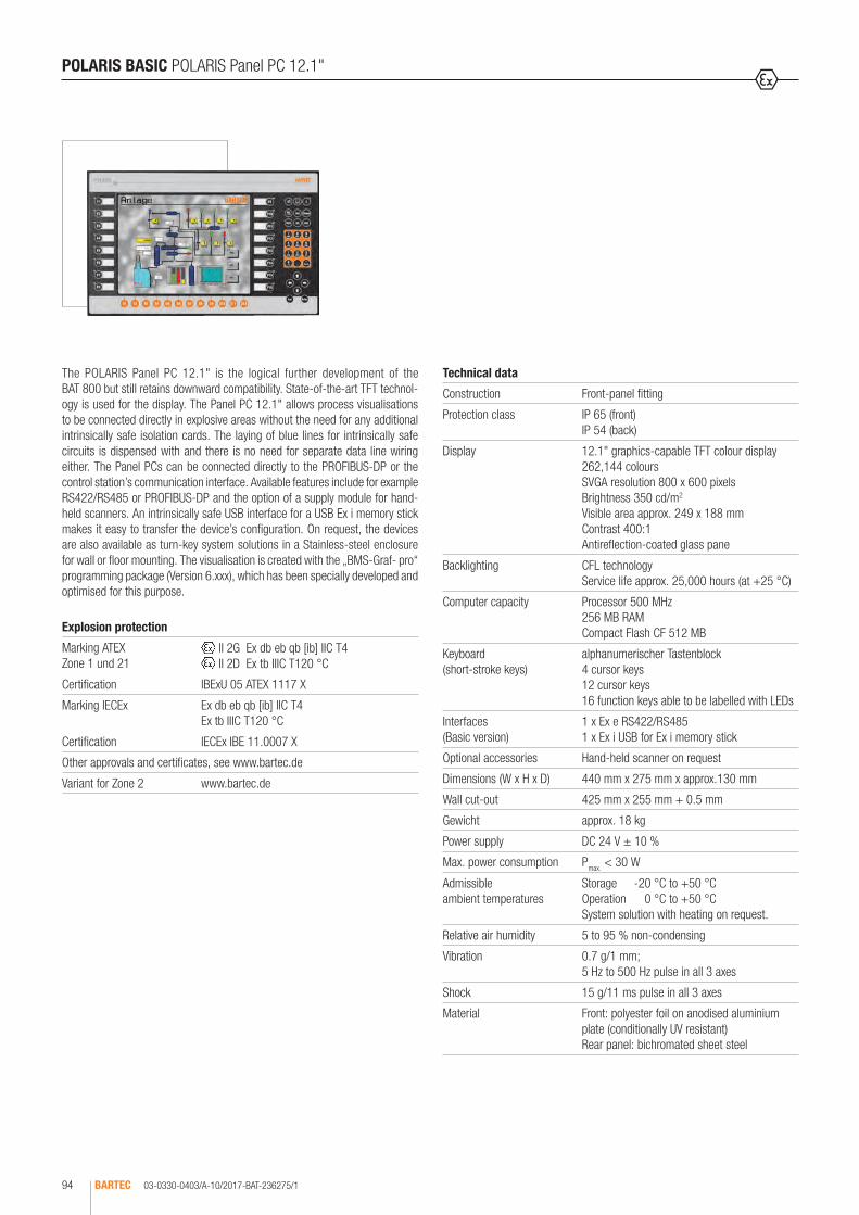
03-0330-0403/A-10/2017-BAT-236275/1BARTEC94
The POLARIS Panel PC 12.1" is the logical further development of the BAT 800 but still retains downward compatibility. State-of-the-art TFT technol-ogy is used for the display. The Panel PC 12.1" allows process visualisations to be connected directly in explosive areas without the need for any additional intrinsically safe isolation cards. The laying of blue lines for intrinsically safe circuits is dispensed with and there is no need for separate data line wiring either. The Panel PCs can be connected directly to the PROFIBUS-DP or the control station’s communication interface. Available features include for example RS422/RS485 or PROFIBUS-DP and the option of a supply module for hand-held scanners. An intrinsically safe USB interface for a USB Ex i memory stick makes it easy to transfer the device’s configuration. On request, the devices are also available as turn-key system solutions in a Stainless-steel enclosure for wall or floor mounting. The visualisation is created with the „BMS-Graf- pro“ programming package (Version 6.xxx), which has been specially developed and optimised for this purpose.
POLARIS BASIC POLARIS Panel PC 12.1"
Technical data
Construction Front-panel fitting
Protection class IP 65 (front) IP 54 (back)
Display 12.1" graphics-capable TFT colour display 262,144 colours SVGA resolution 800 x 600 pixels Brightness 350 cd/m2
Visible area approx. 249 x 188 mm Contrast 400:1 Antireflection-coated glass pane
Backlighting CFL technology Service life approx. 25,000 hours (at +25 °C)
Computer capacity Processor 500 MHz 256 MB RAM Compact Flash CF 512 MB
Keyboard (short-stroke keys)
alphanumerischer Tastenblock 4 cursor keys 12 cursor keys 16 function keys able to be labelled with LEDs
Interfaces (Basic version)
1 x Ex e RS422/RS485 1 x Ex i USB for Ex i memory stick
Optional accessories Hand-held scanner on request
Dimensions (W x H x D) 440 mm x 275 mm x approx.130 mm
Wall cut-out 425 mm x 255 mm + 0.5 mm
Gewicht approx. 18 kg
Power supply DC 24 V ± 10 %
Max. power consumption Pmax. < 30 W
Admissible ambient temperatures
Storage -20 °C to +50 °C Operation 0 °C to +50 °C System solution with heating on request.
Relative air humidity 5 to 95 % non-condensing
Vibration 0.7 g/1 mm; 5 Hz to 500 Hz pulse in all 3 axes
Shock 15 g/11 ms pulse in all 3 axes
Material Front: polyester foil on anodised aluminium plate (conditionally UV resistant) Rear panel: bichromated sheet steel
Explosion protection
Marking ATEX Zone 1 und 21
II 2G Ex db eb qb [ib] IIC T4 II 2D Ex tb IIIC T120 °C
Certification IBExU 05 ATEX 1117 X
Marking IECEx Ex db eb qb [ib] IIC T4 Ex tb IIIC T120 °C
Certification IECEx IBE 11.0007 X
Other approvals and certificates, see www.bartec.de
Variant for Zone 2 www.bartec.de
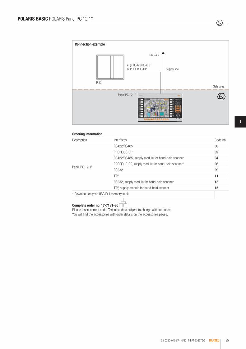
03-0330-0403/A-10/2017-BAT-236275/2 BARTEC 95
1
Ordering information
Description Interfaces Code no.
Panel PC 12.1"
RS422/RS485 00
PROFIBUS-DP* 02
RS422/RS485, supply module for hand-held scanner 04
PROFIBUS-DP, supply module for hand-held scanner* 06
RS232 09
TTY 11
RS232, supply module for hand-held scanner 13
TTY, supply module for hand-held scanner 15
* Download only via USB Ex i memory stick.
Safe area
Connection example
PLC
DC 24 V
Supply line
Panel PC 12.1"
e. g. RS422/RS485 or PROFIBUS-DP
POLARIS BASIC POLARIS Panel PC 12.1"
Complete order no. 17-71V1-30 Please insert correct code. Technical data subject to change without notice. You will find the accessories with order details on the accessories pages.

03-0330-0406/A-10/2017-BAT-236278/1BARTEC96
POLARIS BASIC BMS-Graf-pro 6 Visualisation Software
The BMS-Graf-pro software package is a very convenient tool for the generation of process representations. Individual images and projects are created on the PC and stored in the POLARIS Panel PC, POLARIS Control. The programme ensures that the single images use only a very small amount of memory space. This allows the storage of over 100 images. The well established and highly reliable functions of the BMS Graf are still available for example: input and output fields, bar graphs and vector graphics. All existing project can be integrated within the new software. The completely new WINDOWS based platform is suitable for most popular versions of WINDOWS NT, WIN 2000 and XP. With the selection of the correct protocol driver (please refer to table) connections to various PLC systems are possible. BARTEC is continuously increasing the number of protocols available.
Logic controllers for serial couplingDescription PLCAS511 on S5 Programming Port
S5-95U to 115U
MPI on S7 Programming Port
S7-300 S7-400 with MPI-Box
3964R with RK 512
S5 with communication processors CP524 to CP544 S7-300 with communication processor CP341 S7-400 with communication processor CP441-2
Modbus RTU, Slave and Master
Telemechanique TSX-Series with communication processor TSXSCG1131
AprilAEG A-series with Modbus module,
AEG Modicon, AEG QuantumAllen Bradley SLC500 with Pro Soft module (3150MCM)
PLC5/40 or PLC5/60 with comminicaions board 17-71-DBMM
HIMA H51, H41, H11Yokogawa
SMCC Micro XL with communication processor PX1Centrum CS with communication processor ACM11
GE-FANUC90-30 with communication processor CMM311E90-70 with communication processor CMM711 or PCM711
DCS Eurotherm, DCS Fisher&Porter SistemSixFoxboro DCS 80E, AS21Honeywell TDC3000Fisher Rosemount Delta VSaia PCD
Description PLCMitsubishi A Mitsubishi A with communication processor ASJ71C24COMLI Sattcontrol
Alfa LavalHostlink OMRON SYSMAC CQM1
Logic controllers for PROFIBUS DPDescription PLCSiemens S5-95U with PROFIBUS-DP Master interface
S5-135U with PROFIBUS-DP Master interface EM308C S7-300 with CPU 315-2 DP (Master) S7-400 with CPU 416-2 DP (Master) PCS 7
Hartmann & Braun
Freelance 2000 with field controller
Schneider TSX Premium with PROFIBUS coupling unit AEG Quantum with PROFIBUS coupling unit
Software BMS-Graf-pro is including the latest handling units. For more possibilities ask us.
Ordering information
BMS-Graf-pro 6 Visualisation Software Order no.
German 17-28TF-0071/0100
English 17-28TF-0071/0200
French 17-28TF-0071/0300
Technical data subject to change without notice.

1
POLARIS BASIC Accessories
03-0330-0661/A-10/2017-BAT-318916/1 BARTEC 97
Ordering information
Illustration Description Order no.
Ex i memory stick 17-71VZ-5000
for POLARIS Panel PC and POLARIS Control
Reinforcement frame
Control 05-0205-0011
Panel PC 5.7" 05-0205-0006
Panel PC 10.4" 05-0205-0008
Panel PC 12.1" 05-0205-0007
Mounting clamps set
4 pieces 05-0091-0111
6 pieces 05-0091-0112
Original packing
Control 04-9035-0003
Panel PC 5.7" 04-9035-0004
Panel PC 10.4" 04-9035-0005
Panel PC 12.1" 04-9035-0006

Bestellangaben
Abbildung Beschreibung Abmessungen in mm Bestellnummer
Edelstahlgehäuse Standard
Technische Daten
Material Edelstahl 1.4404; AISI 316 L
Oberfläche Strichschliff
Schutzart IP 65
• zur Bodenmontage mit Standfuß (B x H x T)
Control 450 x 240 x 150 07-56D7-2B00/9002
Panel PC 5,7“ 500 x 280 x 200 07-56D7-9011/9002
Panel PC 10,4“ 560 x 320 x 200 07-56D7-9611/9002
Panel PC 12,1“ 600 x 350 x 200 07-56D7-9711/9002
Komplettlösungen mit Einbauten auf Anfrage
• zur Wandmontage mit Befestigungslaschen (B x H x T)
Control 450 x 240 x 150 07-56D7-2B00/9001
Panel PC 5,7“ 500 x 280 x 200 07-56D7-9011/9001
Panel PC 10,4“ 560 x 320 x 200 07-56D7-9611/9001
Panel PC 12,1“ 600 x 350 x 200 07-56D7-9711/9001
Komplettlösungen mit Einbauten auf Anfrage
POLARIS BASIC Accessories
Ordering information
Illustration Description Dimensions in mm Order no.
Standard stainless-steel enclosure
Technical data
Material Stainless-steel 1.4404; AISI 316 L
Surface Brushed
Protection class IP 65
• for floor mounting with stand (B x H x T)
Control 450 x 240 x 150 07-56D7-2B00/9002
Panel PC 5.7" 500 x 280 x 200 07-56D7-9011/9002
Panel PC 10.4" 560 x 320 x 200 07-56D7-9611/9002
Panel PC 12.1" 600 x 350 x 200 07-56D7-9711/9002
Complete solution with installed equipment on request
• for wall mounting including mounting straps (B x H x T)
Control 450 x 240 x 150 07-56D7-2B00/9001
Panel PC 5.7" 500 x 280 x 200 07-56D7-9011/9001
Panel PC 10.4" 560 x 320 x 200 07-56D7-9611/9001
Panel PC 12.1" 600 x 350 x 200 07-56D7-9711/9001
Complete solution with installed equipment on request
1
B
H
T
1 mounting strap for wall mounting
03-0330-0661/A-10/2017-BAT-318916/1BARTEC98

ANTARES REMOTE I/O SYSTEM

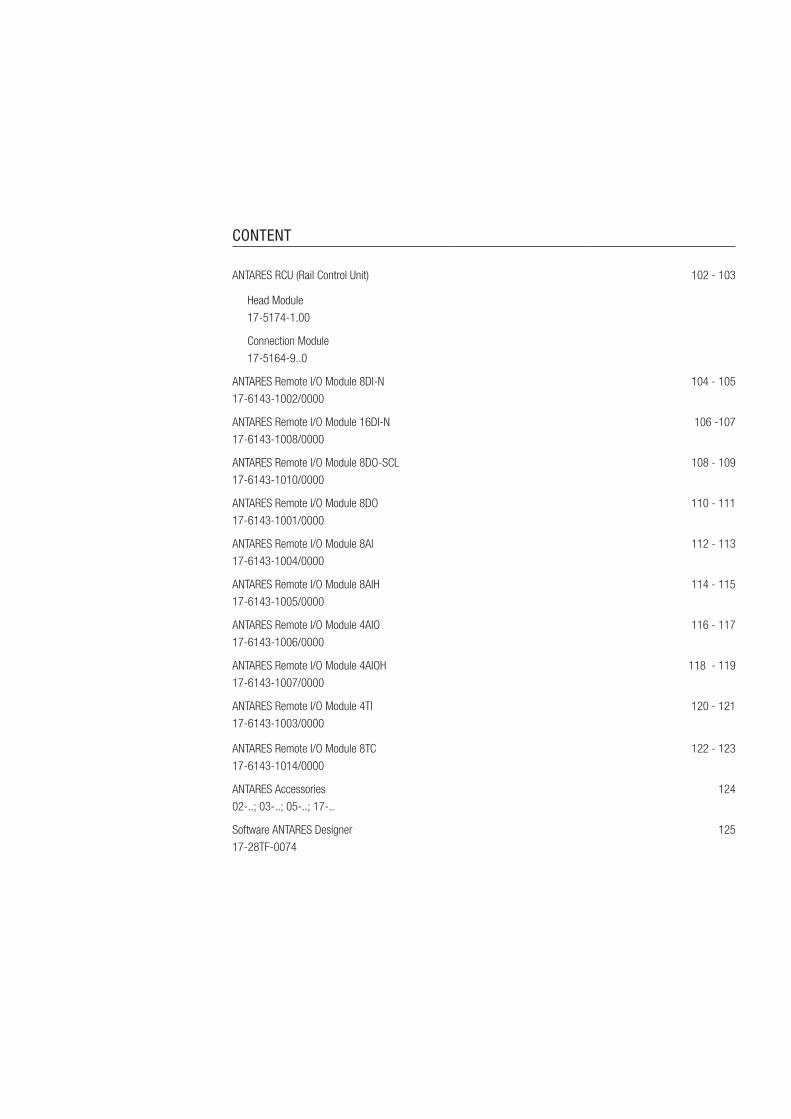
CONTENT
ANTARES RCU (Rail Control Unit) 102 - 103
Head Module 17-5174-1.00
Connection Module 17-5164-9..0
ANTARES Remote I/O Module 8DI-N 17-6143-1002/0000
104 - 105
ANTARES Remote I/O Module 16DI-N 17-6143-1008/0000
106 -107
ANTARES Remote I/O Module 8DO-SCL 17-6143-1010/0000
108 - 109
ANTARES Remote I/O Module 8DO 17-6143-1001/0000
110 - 111
ANTARES Remote I/O Module 8AI 17-6143-1004/0000
112 - 113
ANTARES Remote I/O Module 8AIH 17-6143-1005/0000
114 - 115
ANTARES Remote I/O Module 4AIO 17-6143-1006/0000
116 - 117
ANTARES Remote I/O Module 4AIOH 17-6143-1007/0000
118 - 119
ANTARES Remote I/O Module 4TI 17-6143-1003/0000
120 - 121
ANTARES Remote I/O Module 8TC 17-6143-1014/0000
122 - 123
ANTARES Accessories 02-..; 03-..; 05-..; 17-..
124
Software ANTARES Designer 17-28TF-0074
125

03-0330-0541-10/2017-BAT-291527/1BARTEC102
The Rail Control Unit (RCU) ANTARES is the central unit in the ANTARES sys-tem. It consists of the head module and the connection module. Various field bus and Ethernet-based head modules are available. There is no need to use an isolating repeater to connect them. Redundancy is achieved with no single point of failure by connecting two PROFIBUS-DP RCUs. The head module, consisting of the CPU, the communication interface and an integrated power supply unit, is produced with the Ex d type of protection and is plugged into the corresponding connection module. The innovative interlocking technology ensures a reliable connection. The hot swap capability allows the head module to be replaced even in an explosive atmosphere. The connection module has an integrated Ex e junction box. A version is also available for armoured leads. The system is configured by means of Software ANTARES Designer using the USB interface. See the system description for installation instructions.
ANTARES RCU (Rail Control Unit)
Technical data
Enclosure material Connection module PA Head module aluminium die-casting, PA
Mounting rail TH 35-15 DIN EN/IEC 60715 (steel, galvanised) flush on mounting plate
Supply I/O modules up to max. 32 modules (module dependent)
Electrical connections Ex e Data and power supply cable through tension spring clamp up to 2.5 mm2
Displays LED connection modules Operation LED RUN Communication LED COM Redundancy (primary) LED PRI Error LED ERR
Rated voltage DC 24 V -15 %, +25 %
Power consumption max. 100 W
Overvoltage category II
Degree of contamination 2
Dimensions RCU (W x H x D) 114 mm x 192 mm x 298 mm
Weight approx. 5 kg
Storage and transport temperature
-25 °C to +70 °C
Relative Humidity 5 to 95 %, non-condensing
Vibration (EN/IEC 60068-2-6)
2 g/7 mm; 5 Hz to 200 Hz in all 3 axes
Shock (EN/IEC 60068-2-27)
15 g, 11 ms, ± 3 shocks per direction
Process connection
Internal Bus communication 10 + 2 pole connector
PROFIBUS-DP Full redundancy possible up to 1.5 Mbit/s
Ethernet 100BaseT with integrated switch
PROFINET MODBUS/TCP EtherNet/IP
Configuration
Interface USB
Software ANTARES Designer
Back up SD card
Explosion protection
Marking ATEX II 2G Ex d e [ib] IIC T4 Gb
Certification PTB 11 ATEX 2009 X
Marking IECEx Ex d e [ib] IIC T4 Gb
Certification IECEx PTB 11.0051 X
Marking CSA Class I, Zone 1
Certification CSA 2567944
Other approvals and certificates, see www.bartec.de
Ambient temperature -20 °C to +60 °C
Protection class (EN/IEC 60529)
RCU IP 54 Internal system bus IP 30 (in the ANTARES system construction)

114
192
298
03-0330-0541-10/2017-BAT-291527/2 BARTEC 103
1
Dimensions
ANTARES RCU (Rail Control Unit)
Complete order no. 17-5174-1 00 Please enter code number. Technical data subject to change without notice.
Complete order no. 17-5164-9 0 Please enter code number. Technical data subject to change without notice.
Ordering information Head Module ANTARES
Interface Code no.
PROFIBUS-DP 1
PROFINET 2
MODBUS/TCP 3
EtherNet/IP 4
Ordering information Connection Module ANTARES
Interface Code no. Wire Code no.
EtherNet 9 not armoured 1
PROFIBUS-DP 1 armoured 2
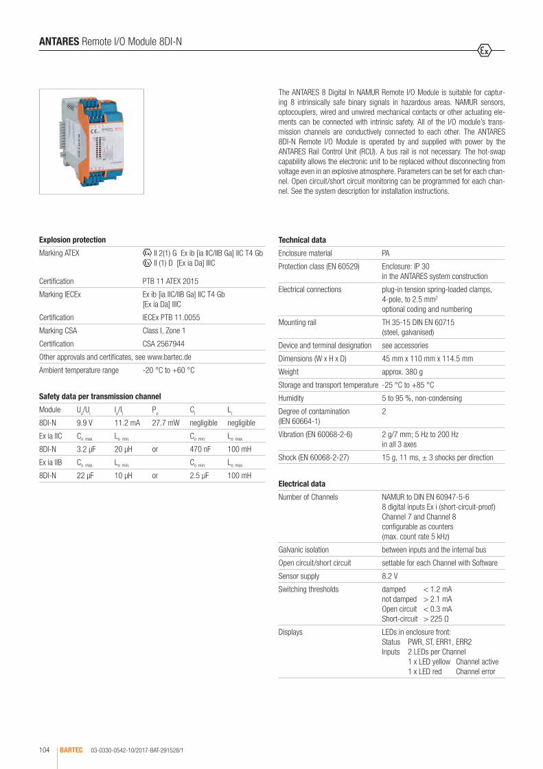
03-0330-0542-10/2017-BAT-291528/1BARTEC104
The ANTARES 8 Digital In NAMUR Remote I/O Module is suitable for captur-ing 8 intrinsically safe binary signals in hazardous areas. NAMUR sensors, optocouplers, wired and unwired mechanical contacts or other actuating ele-ments can be connected with intrinsic safety. All of the I/O module’s trans-mission channels are conductively connected to each other. The ANTARES 8DI-N Remote I/O Module is operated by and supplied with power by the ANTARES Rail Control Unit (RCU). A bus rail is not necessary. The hot-swap capability allows the electronic unit to be replaced without disconnecting from voltage even in an explosive atmosphere. Parameters can be set for each chan-nel. Open circuit/short circuit monitoring can be programmed for each chan-nel. See the system description for installation instructions.
ANTARES Remote I/O Module 8DI-N
Explosion protection
Marking ATEX II 2(1) G Ex ib [ia IIC/IIB Ga] IIC T4 Gb II (1) D [Ex ia Da] IIIC
Certification PTB 11 ATEX 2015
Marking IECEx Ex ib [ia IIC/IIB Ga] IIC T4 Gb [Ex ia Da] IIIC
Certification IECEx PTB 11.0055
Marking CSA Class I, Zone 1
Certification CSA 2567944
Other approvals and certificates, see www.bartec.de
Ambient temperature range -20 °C to +60 °C
Technical data
Enclosure material PA
Protection class (EN 60529) Enclosure: IP 30 in the ANTARES system construction
Electrical connections plug-in tension spring-loaded clamps, 4-pole, to 2.5 mm2 optional coding and numbering
Mounting rail TH 35-15 DIN EN 60715 (steel, galvanised)
Device and terminal designation see accessories
Dimensions (W x H x D) 45 mm x 110 mm x 114.5 mm
Weight approx. 380 g
Storage and transport temperature -25 °C to +85 °C
Humidity 5 to 95 %, non-condensing
Degree of contamination (IEN 60664-1)
2
Vibration (EN 60068-2-6) 2 g/7 mm; 5 Hz to 200 Hz in all 3 axes
Shock (EN 60068-2-27) 15 g, 11 ms, ± 3 shocks per direction
Electrical data
Number of Channels NAMUR to DIN EN 60947-5-6 8 digital inputs Ex i (short-circuit-proof) Channel 7 and Channel 8 configurable as counters (max. count rate 5 kHz)
Galvanic isolation between inputs and the internal bus
Open circuit/short circuit settable for each Channel with Software
Sensor supply 8.2 V
Switching thresholds damped < 1.2 mA not damped > 2.1 mA Open circuit < 0.3 mA Short-circuit > 225 Ω
Displays LEDs in enclosure front: Status PWR, ST, ERR1, ERR2 Inputs 2 LEDs per Channel 1 x LED yellow Channel active 1 x LED red Channel error
Safety data per transmission channel
Module Uo/Ui Io/II Po Ci Li
8DI-N 9.9 V 11.2 mA 27.7 mW negligible negligible
Ex ia IIC Co max. Lo min. Co min. Lo max.
8DI-N 3.2 µF 20 µH or 470 nF 100 mH
Ex ia IIB Co max. Lo min. Co min. Lo max.
8DI-N 22 µF 10 µH or 2.5 µF 100 mH

03-0330-0542-10/2017-BAT-291528/2 BARTEC 105
1
ANTARES Remote I/O Module 8DI-N
LED Colour Meaning
PWR GN Power OK, goes out in the event of undervoltage
ST GN Data exchange active
ERR1 RT Communication error
ERR2 RT Error in the module
ON 1-8 GE Channel switched on
ERR 1-8 RT Channel error line break/short circuit
Wiring diagram/terminal assigment Terminal block Terminal Description
X4
X3
X2
X1
X4
7- Minus terminal Channel 7
7+ Plus terminal Channel 7
8- Minus terminal Channel 8
8+ Plus terminal Channel 8
X3
5- Minus terminal Channel 5
5+ Plus terminal Channel 5
6- Minus terminal Channel 6
6+ Plus terminal Channel 6
X2
3+ Plus terminal Channel 3
3- Minus terminal Channel 3
4+ Plus terminal Channel 4
4- Minus terminal Channel 4
X1
1+ Plus terminal Channel 1
1- Minus terminal Channel 1
2+ Plus terminal Channel 2
2- Minus terminal Channel 2
Bestellangaben
Ordering information
Les informations de commande
Данные для заказа
Datos del pedido
Dados para encomenda
Sipariş bilgileri
Version
Version
Version
Версия
Versión
Versão
Versiyon
Versione
Dimensions
110
114,
5
45
Ordering information
ANTARES Remote I/O Module 8DI-N 17-6143-1002/0000
Technical data subject to change without notice.

03-0330-0542-10/2017-BAT-291529/1BARTEC106
The ANTARES 16 Digital In NAMUR Remote I/O Module is suitable for captur-ing 16 intrinsically safe binary signals in hazardous areas. NAMUR sensors, optocouplers, wired and unwired mechanical contacts or other actuating ele-ments can be connected with intrinsic safety. All of the I/O module’s transmis-sion channels are conductively connected to each other. The ANTARES 16DI-N Remote I/O Module is operated by and supplied with power by the ANTARES Rail Control Unit (RCU). A bus rail is not necessary. The hot-swap capability allows the electronic unit to be replaced without disconnecting from voltage even in an explosive atmosphere. Parameters can be set for each channel. Open circuit/short circuit monitoring can be programmed for each channel. See the system description for installation instructions.
ANTARES Remote I/O Module 16DI-N
Technical data
Enclosure material PA
Protection class (EN 60529) Enclosure: IP 30 in the ANTARES system construction
Electrical connections plug-in tension spring-loaded clamps, 4-pole, to 2.5 mm2; optional coding and numbering
Mounting rail TH 35-15 DIN EN 60715 (steel, galvanised))
Device and terminal designation see accessories
Dimensions (W x H x D) 45 mm x 110 mm x 114.5 mm
Weight approx. 490 g
Storage and transport temperature
-25 °C to +85 °C
Humidity 5 to 95 %, non-condensing
Degree of contamination (IEN 60664-1)
2
Vibration (EN 60068-2-6) 2 g/7 mm; 5 Hz to 200 Hz in all 3 axes
Shock (EN 60068-2-27) 15 g, 11 ms, ± 3 shocks per direction
Electrical data
Number of Channels NAMUR to DIN EN 60947-5-6 16 digital inputs Ex i (short-circuit-proof)
Galvanic Isolation between inputs and internal bus
Open circuit/short circuit settable for each Channel with Software
Sensor supply 8.2 V
Switching thresholds damped < 1.2 mA not damped > 2.1 mA Open circuit < 0.3 mA Short-circuit > 225 Ω
Displays LEDs in enclosure front: Status: PWR, ST, ERR1, ERR2 Inputs: 2 LEDs per Channel 1 x LED yellow Channel active 1 x LED red Channel error
Safety data per transmission Channel
Module Uo/Ui Io/II Po Ci Li
16DI-N 9.9 V 11.2 mA 27.7 mW negligible negligible
Ex ia IIC Co max. Lo min. Co min. Lo max.
16 DI-N 3.2 µF 20 µH or 470 nF 100 mH
Ex ia IIB Co max. Lo min. Co min. Lo max.
16 DI-N 22 µF 10 µH or 2.5 µF 100 mH
Explosion protection
Marking ATEX II 2(1) G Ex ib [ia IIC/IIB Ga] IIC T4 Gb II (1) D [Ex ia Da] IIIC
Certification PTB 11 ATEX 2015
Marking IECEx Ex ib [ia IIC/IIB Ga] IIC T4 Gb [Ex ia Da] IIIC
Certification IECEx PTB 11.0055
Marking CSA Class I, Zone 1
Certification CSA 2567944
Other approvals and certificates, see www.bartec.de
Ambient temperature range -20 °C to +60 °C

03-0330-0542-10/2017-BAT-291529/2 BARTEC 107
1
Bestellangaben
Ordering information
Les informations de commande
Данные для заказа
Datos del pedido
Dados para encomenda
Sipariş bilgileri
Version
Version
Version
Версия
Versión
Versão
Versiyon
Versione
Wiring diagram/terminal assigment Terminal block Terminal Description Terminal block Terminal Description
X4 X8
X6
X3 X7
X5
X2
X1
X4
7- Minus terminal Channel 7
X8
15- Minus terminal Channel 15
7+ Plus terminal Channel 7 15+ Plus terminal Channel 15
8- Minus terminal Channel 8 16- Minus terminal Channel 16
8+ Plus terminal Channel 8 16+ Plus terminal Channel 16
X3
5- Minus terminal Channel 5
X7
13- Minus terminal Channel 13
5+ Plus terminal Channel 5 13+ Plus terminal Channel 13
6- Minus terminal Channel 6 14- Minus terminal Channel 14
6+ Plus terminal Channel 6 14+ Plus terminal Channel 14
X2
3+ Plus terminal Channel 3
X6
11+ Plus terminal Channel 11
3- Minus terminal Channel 3 11- Minus terminal Channel 11
4+ Plus terminal Channel 4 12+ Plus terminal Channel 12
4- Minus terminal Channel 4 12- Minus terminal Channel 12
X1
1+ Plus terminal Channel 1
X5
9+ Plus terminal Channel 9
1- Minus terminal Channel 1 9- Minus terminal Channel 9
2+ Plus terminal Channel 2 10+ Plus terminal Channel 10
2- Minus terminal Channel 2 10- Minus terminal Channel 10
ANTARES Remote I/O Module 16DI-N
LED Colour Meaning
PWR GN Power OK, goes out in the event of undervoltage
ST GN Data exchange active
ERR1 RT Communication error
ERR2 RT Error in the module
ON 1-16 GE Channel switched on
ERR 1-16 RT Channel error line break/short circuit
Ordering information
ANTARES Remote I/O Modul 16DI-N 17-6143-1008/0000
Technical data subject to change without notice.
Dimensions
110
114,
5
45
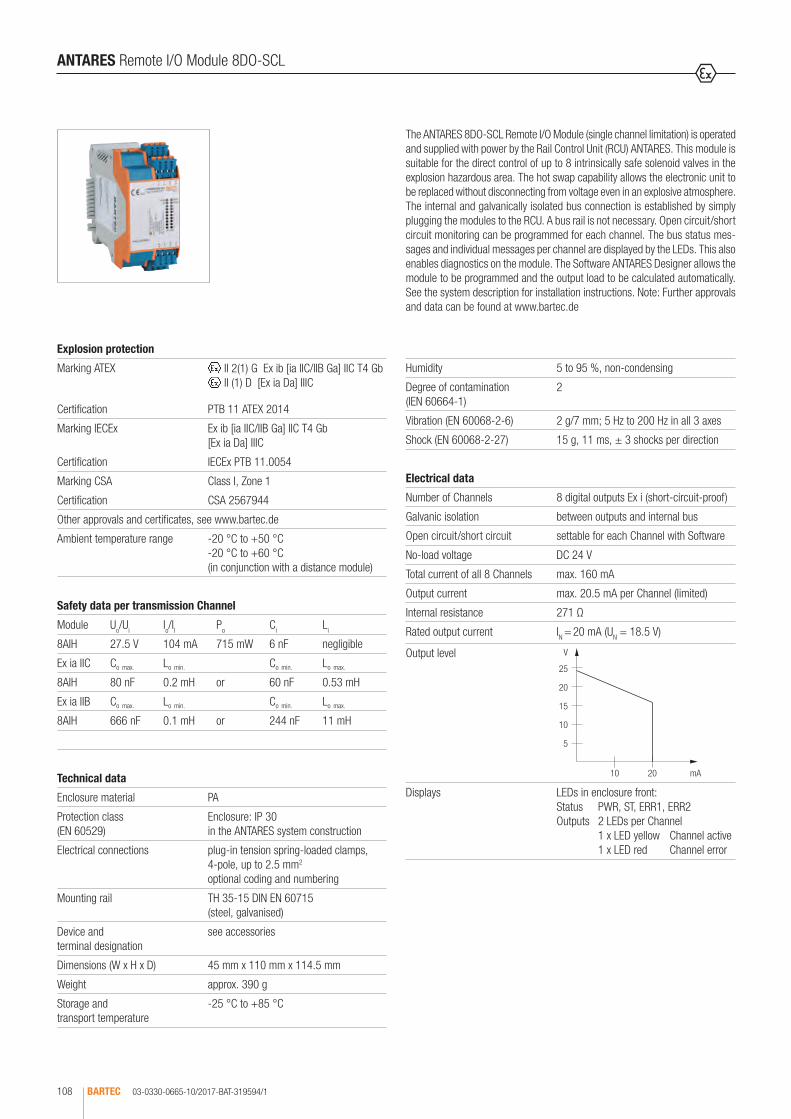
03-0330-0665-10/2017-BAT-319594/1BARTEC108
The ANTARES 8DO-SCL Remote I/O Module (single channel limitation) is operated and supplied with power by the Rail Control Unit (RCU) ANTARES. This module is suitable for the direct control of up to 8 intrinsically safe solenoid valves in the explosion hazardous area. The hot swap capability allows the electronic unit to be replaced without disconnecting from voltage even in an explosive atmosphere. The internal and galvanically isolated bus connection is established by simply plugging the modules to the RCU. A bus rail is not necessary. Open circuit/short circuit monitoring can be programmed for each channel. The bus status mes-sages and individual messages per channel are displayed by the LEDs. This also enables diagnostics on the module. The Software ANTARES Designer allows the module to be programmed and the output load to be calculated automatically. See the system description for installation instructions. Note: Further approvals and data can be found at www.bartec.de
ANTARES Remote I/O Module 8DO-SCL
Explosion protection
Marking ATEX II 2(1) G Ex ib [ia IIC/IIB Ga] IIC T4 Gb II (1) D [Ex ia Da] IIIC
Certification PTB 11 ATEX 2014
Marking IECEx Ex ib [ia IIC/IIB Ga] IIC T4 Gb [Ex ia Da] IIIC
Certification IECEx PTB 11.0054
Marking CSA Class I, Zone 1
Certification CSA 2567944
Other approvals and certificates, see www.bartec.de
Ambient temperature range -20 °C to +50 °C -20 °C to +60 °C (in conjunction with a distance module)
Technical data
Enclosure material PA
Protection class (EN 60529)
Enclosure: IP 30 in the ANTARES system construction
Electrical connections plug-in tension spring-loaded clamps, 4-pole, up to 2.5 mm2 optional coding and numbering
Mounting rail TH 35-15 DIN EN 60715 (steel, galvanised)
Device and terminal designation
see accessories
Dimensions (W x H x D) 45 mm x 110 mm x 114.5 mm
Weight approx. 390 g
Storage and transport temperature
-25 °C to +85 °C
Safety data per transmission Channel
Module Uo/Ui Io/II Po Ci Li
8AIH 27.5 V 104 mA 715 mW 6 nF negligible
Ex ia IIC Co max. Lo min. Co min. Lo max.
8AIH 80 nF 0.2 mH or 60 nF 0.53 mH
Ex ia IIB Co max. Lo min. Co min. Lo max.
8AIH 666 nF 0.1 mH or 244 nF 11 mH
Humidity 5 to 95 %, non-condensing
Degree of contamination (IEN 60664-1)
2
Vibration (EN 60068-2-6) 2 g/7 mm; 5 Hz to 200 Hz in all 3 axes
Shock (EN 60068-2-27) 15 g, 11 ms, ± 3 shocks per direction
Electrical data
Number of Channels 8 digital outputs Ex i (short-circuit-proof)
Galvanic isolation between outputs and internal bus
Open circuit/short circuit settable for each Channel with Software
No-load voltage DC 24 V
Total current of all 8 Channels max. 160 mA
Output current max. 20.5 mA per Channel (limited)
Internal resistance 271 Ω
Rated output current IN = 20 mA (UN = 18.5 V)
Output level V
25
20
15
10
5
10 20 mA
Displays LEDs in enclosure front: Status PWR, ST, ERR1, ERR2 Outputs 2 LEDs per Channel 1 x LED yellow Channel active 1 x LED red Channel error

03-0330-0665-10/2017-BAT-319594/2 BARTEC 109
1
ANTARES Remote I/O Module 8DO-SCL
Dimensions
110
114.
5
45
LED Colour Meaning
PWR GN Power OK, goes out in the event of undervoltage
ST GN Data exchange active
ERR1 RT Communication error
ERR2 RT Error in the module
ON 1-8 GE Channel switched on
ERR 1-8 RT Channel error line break/short circuit
Wiring diagram/terminal assigment Terminal block Terminal Description
X4
X3
X2
X1
X4
7- Minus terminal Channel 7
7+ Plus terminal Channel 7
8- Minus terminal Channel 8
8+ Plus terminal Channel 8
X3
5- Minus terminal Channel 5
5+ Plus terminal Channel 5
6- Minus terminal Channel 6
6+ Plus terminal Channel 6
X2
3+ Plus terminal Channel 3
3- Minus terminal Channel 3
4+ Plus terminal Channel 4
4- Minus terminal Channel 4
X1
1+ Plus terminal Channel 1
1- Minus terminal Channel 1
2+ Plus terminal Channel 2
2- Minus terminal Channel 2
Ordering information
ANTARES Remote I/O Module 8DO-SCL 17-6143-1010/0000
Technical data subject to change without notice.

03-0330-0544-10/2017-BAT-291530/1BARTEC110
The ANTARES 8DO Remote I/O Module is suitable for capturing 8 intrinsically safe binary signals in hazardous areas. NAMUR sensors, optocouplers, wired and unwired mechanical contacts or other actuating elements can be con-nected with intrinsic safety. All of the I/O module’s transmission channels are conductively connected to each other. The ANTARES 8D0 Remote I/O Module is operated by and supplied with power by the ANTARES Rail Control Unit (RCU). A bus rail is not necessary. The hot-swap capability allows the electronic unit to be replaced without disconnecting from voltage even in an explosive atmo-sphere. Parameters can be set for each channel. Open circuit/short circuit monitoring can be programmed for each channel. See the system description for installation instructions.
ANTARES Remote I/O Module 8DO
Explosion protection
Marking ATEX II 2(1) G Ex ib [ia IIC/IIB Ga] IIC T4 Gb II (1) D [Ex ia Da] IIIC
Certification PTB 11 ATEX 2015
Marking IECEx Ex ib [ia IIC/IIB Ga] IIC T4 Gb [Ex ia Da] IIIC
Certification IECEx PTB 11.0055
Marking CSA Class I, Zone 1
Certification CSA 2567944
Other approvals and certificates, see www.bartec.de
Ambient temperature range -20 °C to +50 °C -20 °C to +60 °C (in conjunction with a distance module)
Technical data
Enclosure material PA
Protection class (EN 60529) Enclosure: IP 30 in the ANTARES system construction
Electrical connections plug-in tension spring-loaded clamps, 4-pole up to 2.5 mm2, optional coding and numbering
Mounting rail TH 35-15 DIN EN 60715 (steel, galvanised)
Device and terminal designation see accessories
Dimensions (W x H x D) 45 mm x 110 mm x 114.5 mm
Weight approx. 390 g
Storage and transport temperature -25 °C to +85 °C
Humidity 5 to 95 % non-condensing
Safety data per transmission Channel
Module Uo/Ui Io/II Po Ci Li
8DO 27.5 V 104 mA 715 mW 6 nF negligible
Ex ia IIC Co max. Lo min. Co min. Lo max.
8DO 80 nF 0.2 mH or 60 nF 0.53 mH
Ex ia IIB Co max. Lo min. Co min. Lo max.
8DO 666 nF 0.1 mH or 244 nF 11 mH
Degree of contamination (IEN 60664-1)
2
Vibration (EN 60068-2-6) 2 g/7 mm; 5 Hz to 200 Hz in all 3 axes
Shock (EN 60068-2-27) 15 g, 11 ms, ± 3 shocks per direction
Electrical data
Number of Channels 8 digital outputs Ex i (short-circuit-proof)
Galvanic Isolation between outputs and internal bus
Open circuit/short circuit settable for each Channel with Software
No-load voltage DC 24 V
Total current of all 8 Channels max. 160 mA (limited)
Output current max. 40 mA per Channel
Internal resistance 271 Ω
Rated output current IN = 20 mA (UN = 18.5 V)
Output level
Currents between 40 mA and 70 mA can also be supplied to each channel. For this purpose, the short-circuit monitoring for the channel concerned must be switched off in the Antares Designer. This must, however, be checked in each case against the relevant requirement. The total current of 160 mA for the module continues to apply in each case. Accordingly, if the channel current is high, the number of available outputs per module will be reduced.
V
25
20
15
10
5
10 20 30 40 mA
Displays LEDs in enclosure front: Status: PWR, ST, ERR1, ERR2 Outputs: 2 LEDs per Channel 1 x LED yellow Channel active 1 x LED red Channel error

03-0330-0544-10/2017-BAT-291530/2 BARTEC 111
1
ANTARES Remote I/O Module 8DO
LED Colour Meaning
PWR GN Power OK, goes out in the event of undervoltage
ST GN Data exchange active
ERR1 RT Communication error
ERR2 RT Error in the module
ON 1-8 GE Channel switched on
ERR 1-8 RT Channel error line break/short circuit
Wiring diagram/terminal assigment Terminal block Terminal Description
X4
X3
X2
X1
X4
7- Minus terminal Channel 7
7+ Plus terminal Channel 7
8- Minus terminal Channel 8
8+ Plus terminal Channel 8
X3
5- Minus terminal Channel 5
5+ Plus terminal Channel 5
6- Minus terminal Channel 6
6+ Plus terminal Channel 6
X2
3+ Plus terminal Channel 3
3- Minus terminal Channel 3
4+ Plus terminal Channel 4
4- Minus terminal Channel 4
X1
1+ Plus terminal Channel 1
1- Minus terminal Channel 1
2+ Plus terminal Channel 2
2- Minus terminal Channel 2
Ordering information
ANTARES Remote I/O Module 8DO 17-6143-1001/0000
Technical data subject to change without notice.
Bestellangaben
Ordering information
Les informations de commande
Данные для заказа
Datos del pedido
Dados para encomenda
Sipariş bilgileri
Version
Version
Version
Версия
Versão
Versiyon
Versione
Dimensions
110
114,
5
45

03-0330-0545-10/2017-BAT-291531/1BARTEC112
The ANTARES 8AI Remote I/O Module is suitable for the direct linking of 8 intrinsically safe two-conductor transmitters. NAMUR sensors, optocouplers, wired and unwired mechanical contacts or other actuating elements can be connected with intrinsic safety. All of the I/O module’s transmission chan-nels are conductively connected to each other. The ANTARES 8AI Remote I/O Module is operated by and supplied with power by the ANTARES Rail Control Unit (RCU). A bus rail is not necessary. The hot-swap capability allows the electronic unit to be replaced without disconnecting from voltage even in an explosive atmosphere. Parameters can be set for each channel. Open circuit/short circuit monitoring can be programmed for each channel. See the system description for installation instructions.
ANTARES Remote I/O Module 8AI
Explosion protection
Marking ATEX II 2(1) G Ex ib [ia IIC/IIB Ga] IIC T4 Gb II (1) D [Ex ia Da] IIIC
Certification PTB 11 ATEX 2017
Marking IECEx Ex ib [ia IIC/IIB Ga] IIC T4 Gb [Ex ia Da] IIIC
Certification IECEx PTB 11.0059
Marking CSA Class I, Zone 1
Certification CSA 2567944
Other approvals and certificates, see www.bartec.de
Ambient temperature range -20 °C to +50 °C -20 °C to +60 °C (in conjunction with a distance module)
Technical data
Enclosure material PA
Protection class (EN 60529)
Enclosure: IP 30 in the ANTARES system construction
Electrical connections plug-in tension spring-loaded clamps, 4-pole, up to 2.5 mm2 optional coding and numbering
Mounting rail TH 35-15 DIN EN 60715 (steel, galvanised)
Device and terminal designation
see accessories
Dimensions (W x H x D) 45 mm x 110 mm x 114.5 mm
Weight approx. 390 g
Storage and transport temperature
-25 °C to +85 °C
Humidity 5 to 95 %, non-condensing
Degree of contamination (IEN 60664-1)
2
Vibration (EN 60068-2-6) 2 g/7 mm; 5 Hz to 200 Hz in all 3 axes
Shock (EN 60068-2-27) 15 g, 11 ms, ± 3 shocks per direction
Electrical data
Number of Channels 8 analog inputs Ex i (short-circuit-proof)
Galvanic Isolation between inputs and internal bus
Open circuit/short circuit settable for each Channel with Software
Signal range 4 to 20 mA
Signal min. 0 mA max. 20.5 mA
Short-circuit current max. 20.8 mA
Input resistance Ri = 10 Ω
Resolution 16 bit (15 bit + prefix)
Tolerance ± 0.1 % of the measuring range at +25 °C
Influence of the ambient temperature
± 0.01 %/K of the measuring range
Minimum voltage at 20 mA 16 V
Displays LEDs in enclosure front: Status: PWR, ST, ERR1, ERR2 Inputs: for each Channel 1 LED ERR
Safety data per transmission Channel
Module Uo/Ui Io/II Po Ci Li
8AI 27.5 V 87 mA 598 mW 6 nF negligible
Ex ia IIC Co max. Lo min. Co min. Lo max.
8AI 79 nF 0.2 mH or 37 nF 1.7 mH
Ex ia IIB Co max. Lo min. Co min. Lo max.
8AI 666 nF 0.1 mH or 264 nF 16 mH
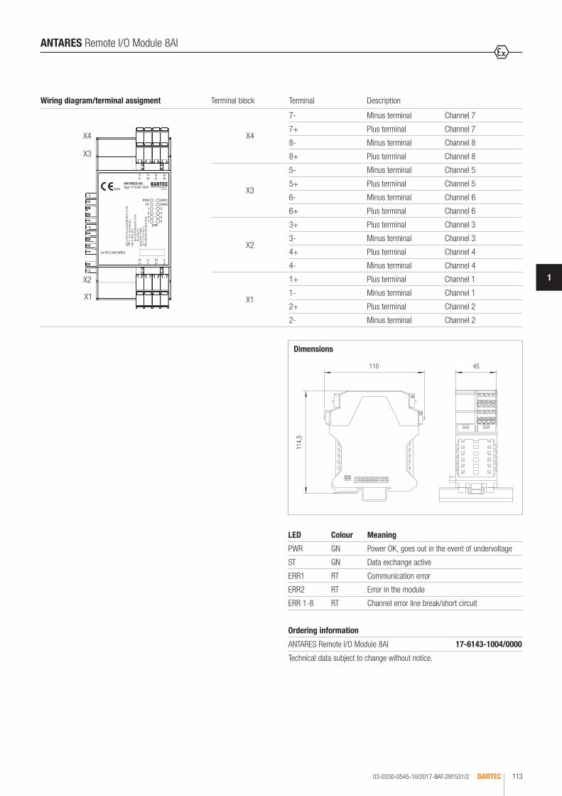
03-0330-0545-10/2017-BAT-291531/2 BARTEC 113
1
ANTARES Remote I/O Module 8AI
Dimensions
110
114,
5
45
LED Colour Meaning
PWR GN Power OK, goes out in the event of undervoltage
ST GN Data exchange active
ERR1 RT Communication error
ERR2 RT Error in the module
ERR 1-8 RT Channel error line break/short circuit
Wiring diagram/terminal assigment Terminal block Terminal Description
X4
X3
X2
X1
X4
7- Minus terminal Channel 7
7+ Plus terminal Channel 7
8- Minus terminal Channel 8
8+ Plus terminal Channel 8
X3
5- Minus terminal Channel 5
5+ Plus terminal Channel 5
6- Minus terminal Channel 6
6+ Plus terminal Channel 6
X2
3+ Plus terminal Channel 3
3- Minus terminal Channel 3
4+ Plus terminal Channel 4
4- Minus terminal Channel 4
X1
1+ Plus terminal Channel 1
1- Minus terminal Channel 1
2+ Plus terminal Channel 2
2- Minus terminal Channel 2
Ordering information
ANTARES Remote I/O Module 8AI 17-6143-1004/0000
Technical data subject to change without notice.
Bestellangaben
Ordering information
Les informations de commande
Данные для заказа
Datos del pedido
Dados para encomenda
Sipariş bilgileri

03-0330-0546-10/2017-BAT-291532/1BARTEC114
The ANTARES 8AIH Remote I/O Module is suitable for the direct linking of 8 intrinsically safe two-conductor transmitters. NAMUR sensors, optocou-plers, wired and unwired mechanical contacts or other actuating elements can be connected with intrinsic safety. All of the I/O module’s transmission chan-nels are conductively connected to each other. The ANTARES 8AI Remote I/O Module is operated by and supplied with power by the ANTARES Rail Control Unit (RCU). A bus rail is not necessary. The hot-swap capability allows the electronic unit to be replaced without disconnecting from voltage even in an explosive atmosphere. Parameters can be set for each channel. Open circuit/short circuit monitoring can be programmed for each channel. See the system description for installation instructions.
ANTARES Remote I/O Module 8AIH
Explosion protection
Marking ATEX II 2(1) G Ex ib [ia IIC/IIB Ga] IIC T4 Gb II (1) D [Ex ia Da] IIIC
Certification PTB 11 ATEX 2017
Marking IECEx Ex ib [ia IIC/IIB Ga] IIC T4 Gb [Ex ia Da] IIIC
Certification IECEx PTB 11.0059
Marking CSA Class I, Zone 1
Certification CSA 2567944
Other approvals and certificates, see www.bartec.de
Ambient temperature range -20 °C to +50 °C -20 °C to +60 °C (in conjunction with a distance module)
Technical data
Enclosure material PA
Protection class (EN 60529) Enclosure: IP 30 in the ANTARES system construction
Electrical connections plug-in tension spring-loaded clamps, 4-pole, up to 2.5 mm2 optional coding and numbering
Mounting rail TH 35-15 DIN EN 60715 (steel, galvanised)
Device and terminal designation see accessories
Dimensions (W x H x D) 45 mm x 110 mm x 114.5 mm
Weight approx. 390 g
Storage and transport temperature -25 °C to +85 °C
Humidity 5 to 95 %, non-condensing
Degree of contamination (IEN 60664-1)
2
Vibration (EN 60068-2-6) 2 g/7 mm; 5 Hz to 200 Hz in all 3 axes
Shock (EN 60068-2-27) 15 g, 11 ms, ± 3 shocks per direction
Electrical data
Number of Channels 8 analog inputs Ex i HART (short-circuit-proof)
Galvanic Isolation between inputs and internal bus
Open circuit/short circuit settable for each Channel with Software
Signal range 4 to 20 mA
Signal min. 0 mA max. 20.5 mA
Short-circuit current max. 21 mA
Input resistance Ri = 10 Ω
Resolution 16 bit (15 bit + prefix)
Tolerance ± 0.1 % of the measuring range at +25 °C
Influence of the ambient temperature
± 0.01 %/K of the measuring range
Minimum voltage at 20 mA 16 V
Displays LEDs in enclosure front: Status: PWR, ST, ERR1, ERR2 Inputs: per Channel 1 LED ERR
Safety data per transmission Channel
Module Uo/Ui Io/II Po Ci Li
8AIH 27.5 V 87 mA 598 mW 6 nF negligible
Ex ia IIC Co max. Lo min. Co min. Lo max.
8AIH 79 nF 0.2 mH or 37 nF 1.7 mH
Ex ia IIB Co max. Lo min. Co min. Lo max.
8AIH 666 nF 0.1 mH or 264 nF 16 mH

03-0330-0546-10/2017-BAT-291532/2 BARTEC 115
1
ANTARES Remote I/O Module 8AIH
Dimensions
110
114,
5
45
LED Colour MeaningPWR GN Power OK, goes out in the event of undervoltage
ST GN Data exchange active
ERR1 RT Communication error
ERR2 RT Error in the module
ERR 1-8 RT Channel error line break/short circuit
Wiring diagram/terminal assigment Terminal block Terminal Description
X4
X3
X2
X1
X4
7- Minus terminal Channel 7
7+ Plus terminal Channel 7
8- Minus terminal Channel 8
8+ Plus terminal Channel 8
X3
5- Minus terminal Channel 5
5+ Plus terminal Channel 5
6- Minus terminal Channel 6
6+ Plus terminal Channel 6
X2
3+ Plus terminal Channel 3
3- Minus terminal Channel 3
4+ Plus terminal Channel 4
4- Minus terminal Channel 4
X1
1+ Plus terminal Channel 1
1- Minus terminal Channel 1
2+ Plus terminal Channel 2
2- Minus terminal Channel 2
Ordering information
ANTARES Remote I/O Module 8AIH 17-6143-1005/0000
Technical data subject to change without notice.
Bestellangaben
Ordering informations
Les informations de commande
Данные для заказа
Datos del pedido
Dados para encomenda
Sipariş bilgileri

03-0330-0547-10/2017-BAT-291533/1BARTEC116
The ANTARES 4AIO Remote I/O Module is operated and supplied with power by means of the Rail Control Unit (RCU) ANTARES. This module allows the direct linking of 4 intrinsically safe transmitters with 2, 3 or 4 conductors or the output of 0 to 20 mA or 4 to 20 mA signals. The hot-swap capability allows the electronic unit to be replaced without disconnecting from voltage even in an explosive atmosphere. The internal and galvanically isolated bus connection is established by simply plugging the modules to the RCU. A bus rail is not necessary. Open circuit/short circuit monitoring can be programmed for each channel. The bus status messages and individual messages per channel are displayed by the LEDs. This also enables diagnostics on the module. The Software ANTARES Designer allows parameters to be set for the signal range, channel type (in or out) and a 4-stage input filter for each channel. See the system description for installation instructions.
ANTARES Remote I/O Module 4AIO
Explosion protection
Marking ATEX II 2(1) G Ex ib [ia IIC/IIB Ga] IIC T4 Gb II (1) D [Ex ia Da] IIIC
Certification PTB 11 ATEX 2018
Marking IECEx Ex ib [ia IIC/IIB Ga] IIC T4 Gb [Ex ia Da] IIIC
Certification IECEx PTB 11.0061
Marking CSA Class I, Zone 1
Certification CSA 2567944
Other approvals and certificates, see www.bartec.de
Ambient temperature range -20 °C to +60 °C
Technical data
Enclosure material PA
Protection class (EN 60529) Enclosure: IP 30 in the ANTARES system construction
Electrical connections plug-in tension spring-loaded clamps, up to 2.5 mm2 optional coding and numbering
Mounting rail TH 35-15 DIN EN 60715 (steel, galvanised)
Device and terminal designation see accessories
Dimensions (W x H x D) 45 mm x 110 mm x 114.5 mm
Weight approx. 390 g
Storage and transport temperature -25 °C to +85 °C
Humidity 5 to 95 %, non-condensing
Degree of contamination (IEN 60664-1)
2
Vibration (EN 60068-2-6) 2 g/7 mm; 5 Hz to 200 Hz in all 3 axes
Shock (EN 60068-2-27) 15 g, 11 ms, ± 3 shocks per direction
Safety data per transmission ChannelModule Uo/Ui Io/II Po Ci Li
4AIO 27.5 V 87 mA 598 mW 6 nF negligibleEx ia IIC Co max. Lo min. Co min. Lo max.
4AIO 79 nF 0.2 mH or 37 nF 1.7 mHEx ia IIB Co max. Lo min. Co min. Lo max.
4AIO 666 nF 0.1 mH or 264 nF 16 mH
Electrical data
Inputs/outputs
Number of Channels 4 inputs or outputs Ex i (short-circuit-proof) Inputs active/passive
Galvanic Isolation between inputs or outputs and internal bus
Open circuit/short circuit settable for each Channel with Software
Input channel
Signal range 0 to 20 mA or 4 to 20 mA
Signal min. 0 mA, max. 21 mA
Short-circuit current max. 21.3 mA
Input resistance Ri = 10 Ω
Resolution 16 bit (15 bit + prefix)
Tolerance ± 0.1 % of the measuring range at +25 °C
Influence of the ambient temperature
± 0.01 %/K of the measuring range
Minimum voltage at 20 mA 16 V
Output channel
Signal range 0 to 20 mA or 4 to 20 mA
Signal min. 0 mA, max. 21 mA
Short-circuit current max. 21.3 mA
Load max. 750 Ω
Resolution 14 bit
Tolerance ± 0.1 % of the measuring range at +25 °C
Influence of the ambient temperature
± 0.01 %/K of the measuring range
Displays LEDs in enclosure front: Status PWR, ST, ERR1, ERR2 Inputs/ 2 LEDs per Channel Outputs 1 x LED gelb Channel setting 1 x LED rot Channel error

03-0330-0547-10/2017-BAT-291533/2 BARTEC 117
1
ANTARES Remote I/O Module 4AIO
LED Colour MeaningPWR GN Power OK, goes out in the event of undervoltage
ST GN Data exchange active
ERR1 RT Communication error
ERR2 RT Error in the module
ON 1-4 GE Differentiation input/output module
ERR 1-4 RT Channel error line break/short circuit
Wiring diagram/terminal assigment Terminal block Terminal Description
X4
X3
X2
X1
X4
4P- Supply - Channel 4
4S- Signal - Channel 4
4S+ Signal + Channel 4
4P+ Supply + Channel 4
X3
3P- Supply - Channel 3
3S- Signal - Channel 3
3S+ Signal + Channel 3
3P+ Supply + Channel 3
X2
2P+ Supply + Channel 2
2P+ Signal + Channel 2
2S- Signal - Channel 2
2P- Supply - Channel 2
X1
1P+ Supply + Channel 1
1S+ Signal + Channel 1
1S- Signal - Channel 1
1P- Supply - Channel 1
Ordering information
ANTARES Remote I/O Module 4AIO 17-6143-1006/0000
Technical data subject to change without notice.
Passive sensors/ 2 conductor transmitter
Passive sensors/ 3 conductor transmitter
Active sensors/ 4 conductor transmitter
Analog outputs/ 2 conductor actuators
0 - 20 mA4 - 20 mA
+24
V
0 V
0 V
A/D
0 V
P+ S+ S- P-
Sensor supply
Sensor supply
Dimensions
110
114.
5
45
P+ P+ S- P-
0 - 20 mA4 - 20 mA
+24
V
0 V
0 V
A/D
0 V
+24
V
0 V
0 V
A/D
0 V
P+ S+ S- P-
0 - 20 mA4 - 20 mA
P+ S+ S- P-
0 - 20 mA4 - 20 mA
0 - 20 mA4 - 20 mA

03-0330-0548-10/2017-BAT-291534/1BARTEC118
The ANTARES 4AIOH Remote I/O Module is operated and supplied with power by means of the Rail Control Unit (RCU) ANTARES. This module allows the direct linking of 4 intrinsically safe 2-, 3-, 4-conductor transmitters or the output of 0 up to 20 mA or 4 up to 20 mA signals. The hot-swap capability allows the electronic unit to be replaced without disconnecting from voltage even in an explosive atmosphere. The internal and galvanically isolated bus connection is established by simply plugging the modules to the RCU. A bus rail is not neces-sary. Open circuit/short circuit monitoring can be programmed for each channel. The bus status messages and individual messages per channel are displayed by the LEDs. This also enables diagnostics on the module. The Software ANTARES Designer allows parameters to be set for the signal range, channel type (in or out), HART function by DTM and a 4-stage input filter for each channel. See the system description for installation instructions.
ANTARES Remote I/O Module 4AIOH
Explosion protection
Marking ATEX II 2(1) G Ex ib [ia IIC/IIB Ga] IIC T4 Gb II (1) D [Ex ia Da] IIIC
Certification PTB 11 ATEX 2018
Marking IECEx Ex ib [ia IIC/IIB Ga] IIC T4 Gb [Ex ia Da] IIIC
Certification IECEx PTB 11.0061
Marking CSA Class I, Zone 1
Certification CSA 2567944
Other approvals and certificates, see www.bartec.de
Ambient temperature range -20 °C to +50 °C -20 °C to +60 °C (in conjunction with a distance module)
Technical dataEnclosure material PA
Protection class (EN 60529) Enclosure: IP 30 in the ANTARES system construction
Electrical connections plug-in tension spring-loaded clamps, 4-pole up to 2.5 mm2 optional coding and numbering
Mounting rail TH 35-15 DIN EN 60715 (steel, galvanised)
Device and terminal designation see accessories
Dimensions (W x H x D) 45 mm x 110 mm x 114.5 mm
Weight approx. 390 g
Storage and transport temperature
-25 °C to +85 °C
Humidity 5 to 95 %, non-condensing
Degree of contamination (IEN 60664-1)
2
Vibration (EN 60068-2-6) 2 g/7 mm; 5 Hz to 200 Hz in all 3 axes
Shock (EN 60068-2-27) 15 g, 11 ms, ± 3 shocks per direction
Safety data per transmission ChannelModule Uo/Ui Io/II Po Ci Li
4AIOH 27.5 V 87 mA 598 mW 6 nF negligibleEx ia IIC Co max. Lo min. Co min. Lo max.
4AIOH 79 nF 0.2 mH or 37 nF 1.7 mHEx ia IIB Co max. Lo min. Co min. Lo max.
4AIOH 666 nF 0.1 mH or 264 nF 16 mH
Electrical data
Inputs/Outputs
Number of Channels 4 inputs or outputs Ex i (short-circuit-proof) Inputs active/passive
Galvanic Isolation between inputs or outputs and internal bus
Open circuit/short circuit settable for each Channel with Software
Input channel
Signal range 0 to 20 mA or 4 to 20 mA
Signal min. 0 mA, max. 21 mA
Short-circuit current max. 21.3 mA
Input resistance Ri = 10 Ω
Resolution 16 bit (15 bit + prefix)
Tolerance ± 0.1 % of the measuring range at +25 °C
Influence of the ambient temperature
± 0.01 %/K of the measuring range
Minimum voltage at 20 mA 16 V
Output channel
Signal range 0 to 20 mA or 4 to 20 mA
Signal min. 0 mA, max. 21 mA
Short-circuit current max. 21.3 mA
Load max. 750 Ω
Resolution 14 bit
Tolerance ± 0.1 % of the measuring range at +25 °C
Influence of the ambient temperature
± 0.01 %/K of the measuring range
Displays LEDs in enclosure front: Status PWR, ST, ERR1, ERR2 Inputs/ 2 LEDs per Channel Outputs 1 x LED yellow Channel setting 1 x LED red Channel error

03-0330-0548-10/2017-BAT-291534/2 BARTEC 119
1
ANTARES Remote I/O Module 4AIOH
Wiring diagram/terminal assigment Terminal block Terminal Description
X4
X3
X2
X1
X4
4P- Supply - Channel 4
4S- Signal - Channel 4
4S+ Signal + Channel 4
4P+ Supply + Channel 4
X3
3P- Supply - Channel 3
3S- Signal - Channel 3
3S+ Signal + Channel 3
3P+ Supply + Channel 3
X2
2P+ Supply + Channel 2
2P+ Signal + Channel 2
2S- Signal - Channel 2
2P- Supply - Channel 2
X1
1P+ Supply + Channel 1
1S+ Signal + Channel 1
1S- Signal - Channel 1
1P- Supply - Channel 1
Ordering information
ANTARES Remote I/O Module 4AIOH 17-6143-1007/0000
Technical data subject to change without notice.
LED Colour MeaningPWR GN Power OK, goes out in the event of undervoltage
ST GN Data exchange active
ERR1 RT Communication error
ERR2 RT Error in the module
ON 1-4 GE Differentiation input/output module
ERR 1-4 RT Channel error line break/short circuit
0 - 20 mA4 - 20 mA
+24
V
0 V
0 V
A/D
0 V
P+ S+ S- P-
0 - 20 mA4 - 20 mA
0 - 20 mA4 - 20 mA
P+ P+ S- P-
P+ S+ S- P-
0 - 20 mA4 - 20 mA
0 - 20 mA4 - 20 mA
P+ S+ S- P-
Passive sensors/ 2 conductor transmitter
Passive sensors/ 3 conductor transmitter
Active sensors/ 4 conductor transmitter
Analog outputs/ 2 conductor actuators
Dimensions
110
114,
5
45
+24
V
0 V
0 V
A/D
0 V
+24
V
0 V
0 V
A/D
0 V
Sensor supply
Sensor supply
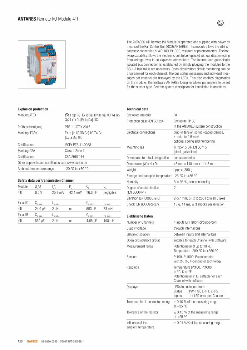
03-0330-0549-10/2017-BAT-291535/1BARTEC120
The ANTARES 4TI Remote I/O Module is operated and supplied with power by means of the Rail Control Unit (RCU) ANTARES. This module allows the intrinsi-cally safe connection of 4 Pt100, Pt1000, resistors or potentiometers. The hot-swap capability allows the electronic unit to be replaced without disconnecting from voltage even in an explosive atmosphere. The internal and galvanically isolated bus connection is established by simply plugging the modules to the RCU. A bus rail is not necessary. Open circuit/short circuit monitoring can be programmed for each channel. The bus status messages and individual mes-sages per channel are displayed by the LEDs. This also enables diagnostics on the module. The Software ANTARES Designer allows parameters to be set for the sensor type. See the system description for installation instructions.
ANTARES Remote I/O Module 4TI
Explosion protection
Marking ATEX II 2(1) G Ex ib [ia IIC/IIB Ga] IIC T4 Gb II (1) D [Ex ia Da] IIIC
Prüfbescheinigung PTB 11 ATEX 2016
Marking IECEx Ex ib [ia IIC/IIB Ga] IIC T4 Gb [Ex ia Da] IIIC
Certification IECEx PTB 11.0058
Marking CSA Class I, Zone 1
Certification CSA 2567944
Other approvals and certificates, see www.bartec.de
Ambient temperature range -20 °C to +60 °C
Technical data
Enclosure material PA
Protection class (EN 60529) Enclosure: IP 30 in the ANTARES system construction
Electrical connections plug-in tension spring-loaded clamps, 4-pole, to 2.5 mm2 optional coding and numbering
Mounting rail TH 35-15 DIN EN 60715 (steel, galvanised)
Device and terminal designation see accessories
Dimensions (W x H x D) 45 mm x 110 mm x 114.5 mm
Weight approx. 380 g
Storage and transport temperature -25 °C to +85 °C
Humidity 5 to 95 %, non-condensing
Degree of contamination (IEN 60664-1)
2
Vibration (EN 60068-2-6) 2 g/7 mm; 5 Hz to 200 Hz in all 3 axes
Shock (EN 60068-2-27) 15 g, 11 ms, ± 3 shocks per direction
Elektrische Daten
Number of Channels 4 inputs Ex i (short-circuit-proof)
Supply voltage through internal bus
Galvanic isolation between inputs and internal bus
Open circuit/short circuit settable for each Channel with Software
Measurement range Potentiometer 0 up to 10 kΩ Temperature -200 °C to +850 °C
Sensors Pt100, Pt1000, Potentiometer with 2-, 3-, 4-conductor technology
Readings Temperature (Pt100, Pt1000) in °C, K or °F Potentiometer in Ω, settable for each Channel with software
Displays LEDs in enclosure front: Status PWR, ST, ERR1, ERR2 Inputs 1 x LED error per Channel
Tolerance for 4-conductor wiring ± 0.10 % of the measuring range at +25 °C
Tolerance of the resistor ± 0.15 % of the measuring range at +25 °C
Influence of the ambient temperature
± 0.01 %/K of the measuring range
Safety data per transmission Channel
Module Uo/Ui Io/II Po Ci Li
4TI 6.5 V 25.9 mA 42.1 mW 16.6 nF negligible
Ex ia IIC Co max. Lo min. Co min. Lo max.
4TI 24.9 µF 2 µH or 593 nF 73 mH
Ex ia IIB Co max. Lo min. Co min. Lo max.
4TI 569 µF 2 µH or 4.68 nF 100 mH

03-0330-0549-10/2017-BAT-291535/2 BARTEC 121
1
ANTARES Remote I/O Module 4TI
Dimensions
110
114,
5
45
Wiring diagram/terminal assigment Terminal block Terminal Description
X4
X3
X2
X1
X4
4P- Supply - Channel 4
4S- Signal - Channel 4
4S+ Signal + Channel 4
4P+ Supply + Channel 4
X3
3P- Supply - Channel 3
3S- Signal - Channel 3
3S+ Signal + Channel 3
3P+ Supply + Channel 3
X2
2P+ Supply + Channel 2
2P+ Signal + Channel 2
2S- Signal - Channel 2
2P- Supply - Channel 2
X1
1P+ Supply + Channel 1
1S+ Signal + Channel 1
1S- Signal - Channel 1
1P- Supply - Channel 1
Ordering information
ANTARES Remote I/O Module 4TI 17-6143-1003/0000
Technical data subject to change without notice.
Connection examples
2-wire Pt100/Pt1000
3-wire Pt100/Pt1000
4-wire Pt100/Pt1000
3-wire potentiometer
LED Colour Meaning
PWR GN Power OK, goes out in the event of undervoltage
ST GN Data exchange active
ERR1 RT Communication error
ERR2 RT Error in the module
ERR 1-4 RT Channel error line break/short circuit
P+
P+ S+
P-
P-
P+
P+
S+
S+
S- P-
P-
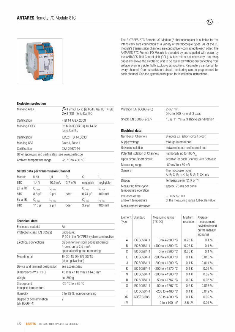
03-0330-0865-07/2016-BAT-388836/1BARTEC122
The ANTARES 8TC Remote I/O Module (8 thermocouples) is suitable for the intrinsically safe connection of a variety of thermocouple types. All of the I/O module’s transmission channels are conductively connected to each other. The ANTARES 8TC Remote I/O Module is operated by and supplied with power by the ANTARES Rail Control Unit (RCU). A bus rail is not necessary. Hot-swap capability allows the electronic unit to be replaced without disconnecting from voltage even in a potentially explosive atmosphere. Parameters can be set for every channel. Open circuit/short circuit monitoring can be programmed for each channel. See the system description for installation instructions.
ANTARES Remote I/O Module 8TC
Explosion protection
Marking ATEX II 2(1)G Ex ib [ia IIC/IIB Ga] IIC T4 Gb II (1)D [Ex ia Da] IIIC
Certification PTB 14 ATEX 2009
Marking IECEx Ex ib [ia IIC/IIB Ga] IIC T4 Gb [Ex ia Da] IIIC
Certification IECEx PTB 14.0033
Marking CSA Class I, Zone 1
Certification CSA 2567944
Other approvals and certificates, see www.bartec.de
Ambient temperature range -20 °C to +60 °C
Technical data
Enclosure material PA
Protection class (EN 60529) Enclosure: IP 30 in the ANTARES system construction
Electrical connections plug-in tension spring-loaded clamps, 4-pole, up to 2.5 mm2; optional coding and numbering
Mounting rail TH 35-15 DIN EN 60715 (steel, galvanised)
Device and terminal designation see accessories
Dimensions (W x H x D) 45 mm x 110 mm x 114.5 mm
Weight ca. 390 g
Storage and transport temperature
-25 °C to +85 °C
Humidity 5 to 95 %, non-condensing
Degree of contamination (EN 60664-1)
2
Safety data per transmission Channel
Module Uo/Ui Io/II Po Ci Li
8TC 1.4 V 10.5 mA 3.7 mW negligible negligible
Ex ia IIC Co max. Lo min. Co min. Lo max.
8TC 8.8 µF 2 µH oder 0.74 µF 100 mH
Ex ia IIB Co max. Lo min. Co min. Lo max.
8TC 115 µF 2 µH oder 3.9 µF 100 mH
Vibration (EN 60068-2-6) 2 g/7 mm; 5 Hz to 200 Hz in all 3 axes
Shock (EN 60068-2-27) 15 g, 11 ms, ± 3 shocks per direction
Electrical data
Number of Channels 8 inputs Ex i (short-circuit proof)
Supply voltage through internal bus
Galvanic isolation between inputs and internal bus
Potential isolation of Channels Funtionally up to 100 Vss
Open circuit/short circuit settable for each Channel with Software
Measuring range -80 mV to +80 mV
Sensors Thermocouple types: A; B; C; E; J; K; N; R; S; T; XK; mV
Display Temperature in °C, K or °F
Measuring time cycle temperature operation
approx. 75 ms per canal
Influence of the ambient temperature
± 0.05 %/10 K of the measuring range full-scale value
Measurement deviation
Element Type
Standard Measuring range (ITS-90)
Medium resolution
Average measurement deviation based on the measur-ing range
A IEC 60584-1 0 to +2500 °C 0.25 K 0.1 %
B IEC 60584-1 +400 to +1800 °C 0.25 K 0.1 %
C IEC 60584-1 0 to +2300 °C 0.25 K 0.1 %
E IEC 60584-1 -200 to +1000 °C 0.1 K 0.013 %
J IEC 60584-1 -200 to +1200 °C 0.1 K 0.014 %
K IEC 60584-1 -200 to +1370 °C 0.1 K 0.02 %
N IEC 60584-1 -200 to +1300 °C 0.1 K 0.02 %
R IEC 60584-1 -50 to +1767 °C 0.2 K 0.05 %
S IEC 60584-1 -50 to +1767 °C 0.2 K 0.053 %
T IEC 60584-1 -200 to +400 °C 0.1 K 0.042 %
XK GOST 8.585 -50 to +800 °C 0.1 K 0.02 %
mV 0 to +100 mV 3.6 µV 0.01 %
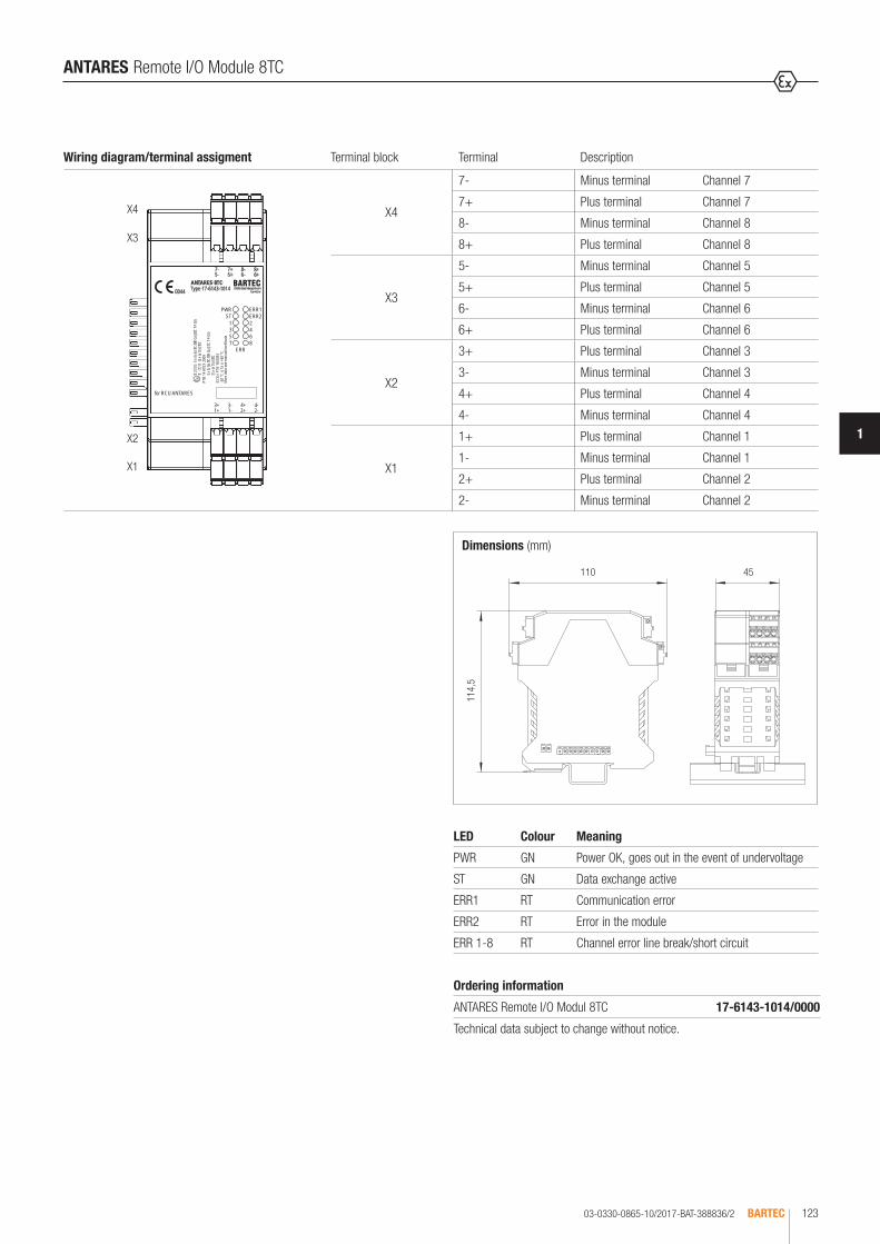
03-0330-0865-10/2017-BAT-388836/2 BARTEC 123
1
ANTARES Remote I/O Module 8TC
Dimensions (mm)
110
114,
5
45
LED Colour Meaning
PWR GN Power OK, goes out in the event of undervoltage
ST GN Data exchange active
ERR1 RT Communication error
ERR2 RT Error in the module
ERR 1-8 RT Channel error line break/short circuit
Wiring diagram/terminal assigment Terminal block Terminal Description
ANTARES 8TCType 17-6143-10140044
97980 Bad MergentheimGermany
for RCU ANTARES
ST ERR2
7- 7+ 8- 8+5- 5+ 6- 6+
ERR8642
PWR ERR1
7531
3+ 3- 4+ 4-1+ 1- 2+ 2-
II 2(1
)G E
x ib [
ia IIC
/IIB G
a] IIC
T4 G
bII
(1) D
[Ex i
a Da]
IIIC
PTB
14 AT
EX 20
09
-20 °
C ≤
Ta ≤
+60
°CMo
re da
ta se
e man
ual/c
ertifi
cate
Ex ib
[ia IIC
/IIB G
a] IIC
T4 G
b[E
x ia D
a] IIIC
IECE
x PTB
14.00
33X4
X2
X3
X1
X4
7- Minus terminal Channel 7
7+ Plus terminal Channel 7
8- Minus terminal Channel 8
8+ Plus terminal Channel 8
X3
5- Minus terminal Channel 5
5+ Plus terminal Channel 5
6- Minus terminal Channel 6
6+ Plus terminal Channel 6
X2
3+ Plus terminal Channel 3
3- Minus terminal Channel 3
4+ Plus terminal Channel 4
4- Minus terminal Channel 4
X1
1+ Plus terminal Channel 1
1- Minus terminal Channel 1
2+ Plus terminal Channel 2
2- Minus terminal Channel 2
Ordering information
ANTARES Remote I/O Modul 8TC 17-6143-1014/0000
Technical data subject to change without notice.
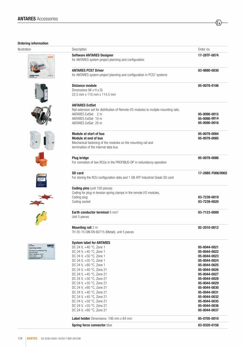
03-0330-0550-10/2017-BAT-291536BARTEC124
ANTARES Accessories
Ordering information
Illustration Description Order no.
Software ANTARES Designerfor ANTARES system project planning and configuration
17-28TF-0074
ANTARES PCS7 Driverfor ANTARES system project planning and configuration in PCS7 systems
03-9880-0030
Distance module Dimensions (W x H x D) 22.5 mm x 110 mm x 114.5 mm
05-0078-0106
ANTARES ExtSet Rail extension set for distribution of Remote I/O modules to mutiple mounting rails.ANTARES ExtSet 2 m ANTARES ExtSet 10 m ANTARES ExtSet 20 m
05-0090-0015 05-0090-0014 05-0090-0016
Module at start of bus Module at end of bus Mechanical fastening of the modules on the mounting rail and termination of the internal data bus
05-0078-0084 05-0078-0085
Plug bridge For connetion of two RCUs in the PROFIBUS-DP in redundancy operation
05-0078-0086
SD card For storing the RCU configuration data and 1 GB ATP Industrial Grade SD card
17-28BE-F006/0002
Coding pins (unit 100 pieces) Coding for plug-in tension spring clamps in the remote I/O modules, Coding plug Coding socket
03-7239-0019 03-7239-0020
Earth conductor terminal 6 mm2 Unit 5 pieces
03-7123-0009
Mounting rail 2 m TH 35-15 DIN EN 60715 (Metall), unit 5 pieces
02-2010-0012
System label for ANTARESDC 24 V, +40 °C, Zone 1 DC 24 V, +45 °C, Zone 1 DC 24 V, +50 °C, Zone 1 DC 24 V, +55 °C, Zone 1 DC 24 V, +60 °C, Zone 1DC 24 V, +40 °C, Zone 21 DC 24 V, +45 °C, Zone 21 DC 24 V, +50 °C, Zone 21 DC 24 V, +55 °C, Zone 21 DC 24 V, +60 °C, Zone 21DC 24 V, +40 °C, Zone 21 DC 24 V, +45 °C, Zone 21 DC 24 V, +50 °C, Zone 21 DC 24 V, +55 °C, Zone 21 DC 24 V, +60 °C, Zone 21
05-0044-0021 05-0044-0022 05-0044-0023 05-0044-0024 05-0044-002505-0044-0026 05-0044-0027 05-0044-0028 05-0044-0029 05-0044-003005-0044-0031 05-0044-0032 05-0044-0035 05-0044-0036 05-0044-0037
Label holder Dimensions: 106 mm x 84 mm 05-0705-0010
Spring force connector blue 03-9320-0158

03-0330-0551-10/2017-BAT-291537 BARTEC 125
1
ANTARES Software ANTARES Designer
Ordering information
Software ANTARES Designer 17-28TF-0074
Technical data subject to change without notice.
The ANTARES designer software has been developed by BARTEC. It operates intuitively, enabling the system to be planned and configured with just a few clicks of the mouse. During the set-up process, users can view their actual system configuration in true-to-scale image; the program also monitors com-pliance with certain limit values such as spacing, power management and the maximum data length on the PROFIBUS. Further functions such as the generation of parts lists and automatic enquiry by email are also possible. The software is also equipped with a CONSTRUCTOR (project or system genera-tor), which calculates the required inputs and outputs and the spare capacity needed for the most cost-effective, i.e. optimal, system. The current output load can be automatically calculated specifically for the digital remote I/O out-put modules. The software has been developed for use with WINDOWS® XP or WINDOWS® 7.
Parts list
Project Planning
Constructor


MODEX BUS SYSTEMS
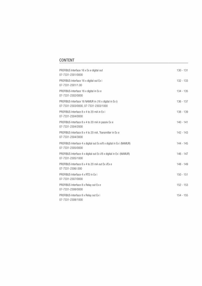
CONTENT
PROFIBUS Interface 16 x Ex e digital out 07-7331-2301/0000
130 - 131
PROFIBUS-Interface 16 x digital out Ex i 07-7331-2301/1.00
132 - 133
PROFIBUS-Interface 16 x digital in Ex e 07-7331-2302/0000
134 - 135
PROFIBUS-Interface 16 NAMUR in (16 x digital in Ex i) 07-7331-2303/0000, 07-7331-2303/1000
136 - 137
PROFIBUS-Interface 8 x 4 to 20 mA in Ex i 07-7331-2304/0000
138 - 139
PROFIBUS-Interface 8 x 4 to 20 mA in passiv Ex e 07-7331-2304/2000
140 - 141
PROFIBUS-Interface 8 x 4 to 20 mA, Transmitter in Ex e 07-7331-2304/3000
142 - 143
PROFIBUS-Interface 4 x digital out Ex e/8 x digital in Ex i (NAMUR) 07-7331-2305/0000
144 - 145
PROFIBUS-Interface 4 x digital out Ex i/8 x digital in Ex i (NAMUR) 07-7331-2305/1000
146 - 147
PROFIBUS-Interface 8 x 4 to 20 mA out Ex i/Ex e 07-7331-2306/.000
148 - 149
PROFIBUS-Interface 4 x RTD in Ex i 07-7331-2307/0000
150 - 151
PROFIBUS-Interface 8 x Relay out Ex e 07-7331-2308/0000
152 - 153
PROFIBUS-Interface 8 x Relay out Ex i 07-7331-2308/1000
154 - 155

PROFIBUS Interface 8 x 4 to 20 mA in/4 x 4 to 20 mA in/out (15-bit plus sign) Ex i 07-7331-230H/.0.1
156 - 157
PROFIBUS Interface 8 x 4 to 20 mA in/4 x 4 to 20 mA in/out (16-bit) 07-7331-230H/.0.0
158 - 159
PROFIBUS-DP Coupler 07-7311-9.WP/K.NO
PROFIBUS-DP Repeater 07-7311-93WP/R.NO
PROFIBUS-DP Gateway DP/IS 07-7311-97WP/K.EO
160 - 161
RS485/PROFIBUS Optical fibre T-coupler 07-7311-97WP/40.0
162 - 163
RS485/PROFIBUS Optical fibre T-coupler 07-7311-97WP/54.0
164 - 165
RS485/PROFIBUS Optical fibre branch coupler 07-7311-97WP/60.0
166 - 167
PROFIBUS-Interface Terminator 07-7311-93WP/0000
168
Resistive coupling element 17-9Z62-00..
169 - 170
Resistive coupling element 1 kΩ/10 kΩ 17-9Z63-0002
171
Process Monitor PM 420ex
17-71MM-1002172

03-0330-0136/G-10/2017-BAT-127309/1BARTEC130
In the Ex e version, the MODEX digital out module can control various actuators using 16 digital outputs. During operation, a channel can be short-circuited on the short-circuit proof outputs (short-circuit proof to a limited extent). For example, solenoid valves, contacts and also signal transmitters with 24 V/max. 500 mA can be controlled as actuators. The controlled actuators can be switched off by an emergency stop via a second power supply connection on the module on terminals U- and U+. The module is connected to the process control system via the PROFIBUS-DP. Coding rotary switches are available for addressing the module. Diagnostics data indicating the status of the outputs with respect to short-circuit or voltage failure can also be transmitted in addi-tion to the user data. This is also displayed on the module itself using LEDs.
Technical data
Construction Flameproof, clip-on enclosure for TH 35 rail
Enclosure material High-quality thermoplastics
Protection class Electronic assembly IP 66 EN/IEC 60529 Terminals IP 20 EN/IEC 60529 Terminals with cover IP 30 EN/IEC 60529
Terminals 2.5 mm², fine stranded
Device designation Front plate for labelling
Displays LEDs on front panel
Storage temperature -40 °C to +60 °C
Ambient temperature -40 °C to +60 °C at T4
Weight 2.1 kg
Explosion protection
Marking ATEX II 2G Ex db e IIC Gb I M2 Ex db e I Mb
Certification PTB 97 ATEX 1066 U
Marking IECEx Ex db e IIC GbEx db e I Mb
Certification IECEx PTB 11.0082U
Marking CSA Class I, Zone 1, IIC A/Ex d e IIC Gb
Certification CSA 2011-2484303U
Other approvals and certificates, see www.bartec.de
Weitere Zulassungen und Prüfbescheinigungen finden Sie unter www.bartec.de
Other approvals and certificates, see www.bartec.de
Autres agréments et certificats, voir www.bartec.de
Другие сертификаты и сертификаты, см. www.bartec.de
Consulte otras homologaciones y certificados de ensayo en www.bartec.de
Outras homologações e certificados de teste encontram-se em www.bartec.de
Diğer onay ve sertifikalar için bkz: www.bartec.de
PROFIBUS Interface 16 x Ex e digital out
Electrical data
Supply voltage electronics (L +, L-)
DC 24 V (20 to 30 V)
Power consumption (L +, L-)
1.5 W
Supply voltage Outputs (U +, U-) suitable for emergency stop
DC 24 V (18 to 30 V)
Power output (U+, U-) 240 W (max.)
Reverse polarity protection (L +, L-, U +, U-)
Yes
Power dissipation max. 7.3 W (Module)
Galvanic isolation Power supply//bus//circuitry//outputs
Bus interface RS485 with screw terminals
Displays Status ON, BF, SF Outputs 16 x LED yellow, active
Outputs
Output voltage U+ -0.18 V
Output current 500 mA at TU = +40 °C400 mA at TU = +60 °C
Short-circuit protection short-circuit proof to a limited extent
Reverse polarity protection Yes
Circuit monitoring Combined fault via bus
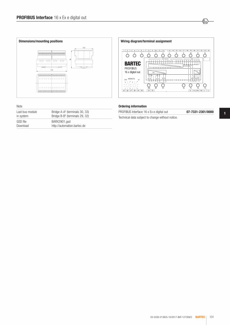
03-0330-0136/G-10/2017-BAT-127309/2 BARTEC 131
1
Ordering information
PROFIBUS Interface 16 x Ex e digital out 07-7331-2301/0000
Technical data subject to change without notice.
102
17096 1 2 3 4 5 6 7 8 9 10 11 12 16 42514131 23222120191817
AP V0V42
PA L- L+25 26 27 28 29 30ADDRESSx10 x1
1
6
9
4
1
6
9
4
GNDOUT1-OUT16
U+U-32 33
1 2 3 4 5 6 7 8 9 10 11 12
25 26 27 28 29 30 32 33
1 2 3 4 5 6 7 8 9 10 11 12
SFBFON 16 15 14 13U- U+ PA L- L+
ABAB
BUS
13 14 15 16 17 18 19 20 21 22 23 24
B Ax x AP
PA
PA
PROFIBUS16 x digital out
Wiring diagram/terminal assignmentDimensions/mounting positions
Note
Last bus module in system
Bridge A-AX (terminals 30, 33) Bridge B-BX (terminals 29, 32)
GSD file Download
BARX2901.gsd http://automation.bartec.de
PROFIBUS Interface 16 x Ex e digital out

03-0330-0277/E-10/2017-BAT-203184/1BARTEC132
PROFIBUS Interface 16 x digital out Ex i
Technical data
Construction Flameproof, clip-on enclosure for TH 35 rail
Enclosure material High-quality thermoplastics
Protection class Electronic assembly IP 66 EN/IEC 60529 Terminals IP 20 EN/IEC 60529 Terminals with cover IP 30 EN/IEC 60529
Terminals 2.5 mm², fine stranded
Device designation Front plate for labelling
Displays LEDs on front panel
Storage temperature -40 °C to +60 °C
Ambient temperature -40 °C to +60 °C at T4
Weight 2.1 kg
In the Ex i version, the MODEX digital out Ex i module can control various actuators using 16 digital outputs. During operation, a channel can be short-circuited on the short-circuit proof outputs (short-circuit proof to a limited extent). For example, intrinsically safe solenoid valves and intrinsically safe signal transmitters can be controlled as actuators. The controlled actuators can be switched off by an emergency stop via a second power supply con-nection on the module on terminals U- and U+. The module is connected to the process control system via the PROFIBUS-DP. Coding rotary switches are available for addressing the module. Diagnostics data indicating the status of the outputs with respect to a disconnection or short-circuit can also be transmitted in addition to the user data. This is also displayed on the module itself using LEDs.
Explosion protection
Marking ATEX II 2(1)G Ex db e [ib] IIC/IIB Gb I M2 Ex db e [ib] I Mb
Certification PTB 97 ATEX 1066 U TÜV 00 ATEX 1649
Marking IECEx Ex db e [ib] IIC/IIB Gb Ex db e [ib] I Mb
Certification IECEx PTB 11.0082U IECEx TUN 11.0035X
Marking CSA Class I, Zone 1, IIC A/Ex d e [ib] IIC Gb
Certification CSA 2011-2484303U
Other approvals and certificates, see www.bartec.de
Installation Type 17-6583-.10./.... Type 17-6583-.11./....
II (2) G / II (2) D [Ex ib Gb] IIC/IIB [Ex ib Db] IIIC/IIIB For further data see verification certificates.
Safety data Type 17-6583-.10./.... U0 = 21 V I0 = 111.6 mA
P0 = 586 mW Characteristic: linear
Ex ib IICLO 2.1 mH 1 mH 0.5 mH 0.2 mH 0.1 mH 0.05 mH
CO 93 nF 96 nF 110 nF 150 nF 180 nF 188 nF
Ex ib IIB/IIIB/IIICLO 12 mH 10 mH 5 mH 0.5 mH 0.2 mH 0.1 mH
CO 540 nF 620 nF 710 nF 750 nF 910 nF 1.1 nF
Type 17-6583-.11./.... U0 = 21 V I0 = 139.2 mA
P0 = 731 mW Characteristic: linear
Ex ib IICLO 1.2 mH 1 mH 0.5 mH 0.2 mH 0.1 mH 0.05 mH
CO 83 nF 86 nF 100 nF 140 nF 170 nF 188 nF
Ex ib IIB/IIIB/IIICLO 7.4 mH 5 mH 0.5 mH 0.2 mH 0.1 mH 0.05 mH
CO 630 nF 680 nF 730 nF 900 nF 1.1 nF 1.27 nF
Electrical data
Supply voltage electronics (L +, L-)
DC 24 V (20 to 30 V)
Power consumption (L +, L-)
2.5 W
Supply voltage Outputs (U +, U-) suitable for emergency stop
DC 24 V (20 to 30 V)
Power output (U+, U-) 15 W (max.)
Reverse polarity protection (L +, L-, U +, U-)
Yes
Power dissipation max. 8 W (Module)
Galvanic isolation Power supply//bus//electronic//outputs
Bus interface RS485 with screw terminals
Displays Status ON, BF, SF, U2 Outputs LED yellow, active LED red, short-circuit
Outputs
Output voltage DC 18.1 V (at U+ ≥ 22 V)
Output data IN = 30 mA Ri = 220 Ω IN = 35 mA Ri = 180 Ω
Short-circuit protection conditionally short-circuit-proof
Reverse polarity protection Yes
Circuit monitoring Combined fault via bus
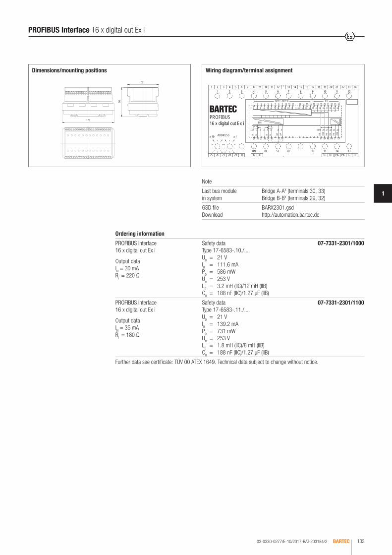
03-0330-0277/E-10/2017-BAT-203184/2 BARTEC 133
1
.11 .15 .16 .17 .18.6 41.5.
X4.1 .2
.8.2
.23 .24
.24.23
1412 161310 1192 5
02.01.9. .12 X1.13
1
6
9
430
ADDRESSx 10 x 1
1
6
9
4
.4 .7
.4
.22.21
02.91.4X9..5
20
.19
.6.3
21
.8 .21 .22
0 VOUT 1 - OUT 16
U+U-32 33
1 2
22
L- L+25 26 27 28 29
0 V 24 V
PA
17 1918
x x
PA
PA0 V 24 V
PAU2ON
15
PA
3 4 5 6 7 8 9 10 11 12
25 26 27 28 29 30 32 33
1 2 3 4 5 6 7 8 9 10 11 12
SF 31415161FBU- U+ PA L- L+
ABABAB
BUS
13 14 15 16 17 18 19 20 21 22 23 24
8763 41 23 24
X1.1 .3
PROFIBUS16 x digital out Ex i
PROFIBUS Interface 16 x digital out Ex i
102
96
Wiring diagram/terminal assignmentDimensions/mounting positions
Note
Last bus module in system
Bridge A-AX (terminals 30, 33) Bridge B-BX (terminals 29, 32)
GSD file Download
BARX2301.gsd http://automation.bartec.de
170
Ordering information
PROFIBUS Interface 16 x digital out Ex i
Output data IN = 30 mA Ri = 220 Ω
Safety data Type 17-6583-.10./.... U0 = 21 V I0 = 111.6 mA
P0 = 586 mW Um = 253 V L0 = 3.2 mH (IIC)/12 mH (IIB) C0 = 188 nF (IIC)/1.27 µF (IIB)
07-7331-2301/1000
PROFIBUS Interface 16 x digital out Ex i
Output data IN = 35 mA Ri = 180 Ω
Safety data Type 17-6583-.11./.... U0 = 21 V I0 = 139.2 mA
P0 = 731 mW Um = 253 V L0 = 1.8 mH (IIC)/8 mH (IIB) C0 = 188 nF (IIC)/1.27 µF (IIB)
07-7331-2301/1100
Further data see certificate: TÜV 00 ATEX 1649. Technical data subject to change without notice.
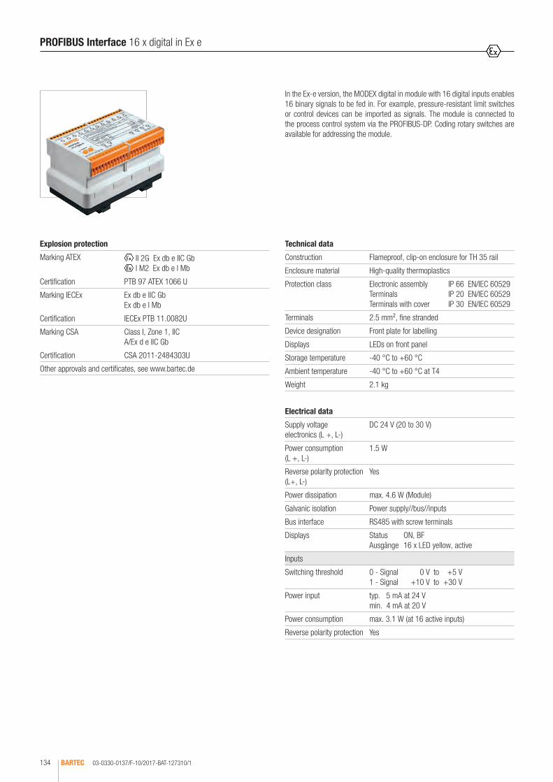
03-0330-0137/F-10/2017-BAT-127310/1BARTEC134
In the Ex-e version, the MODEX digital in module with 16 digital inputs enables 16 binary signals to be fed in. For example, pressure-resistant limit switches or control devices can be imported as signals. The module is connected to the process control system via the PROFIBUS-DP. Coding rotary switches are available for addressing the module.
Technical data
Construction Flameproof, clip-on enclosure for TH 35 rail
Enclosure material High-quality thermoplastics
Protection class Electronic assembly IP 66 EN/IEC 60529 Terminals IP 20 EN/IEC 60529 Terminals with cover IP 30 EN/IEC 60529
Terminals 2.5 mm², fine stranded
Device designation Front plate for labelling
Displays LEDs on front panel
Storage temperature -40 °C to +60 °C
Ambient temperature -40 °C to +60 °C at T4
Weight 2.1 kg
Explosion protection
Marking ATEX II 2G Ex db e IIC Gb I M2 Ex db e I Mb
Certification PTB 97 ATEX 1066 U
Marking IECEx Ex db e IIC GbEx db e I Mb
Certification IECEx PTB 11.0082U
Marking CSA Class I, Zone 1, IIC A/Ex d e IIC Gb
Certification CSA 2011-2484303U
Other approvals and certificates, see www.bartec.de
Weitere Zulassungen und Prüfbescheinigungen finden Sie unter www.bartec.de
Other approvals and certificates, see www.bartec.de
Autres agréments et certificats, voir www.bartec.de
Другие сертификаты и сертификаты, см. www.bartec.de
Consulte otras homologaciones y certificados de ensayo en www.bartec.de
Outras homologações e certificados de teste encontram-se em www.bartec.de
Diğer onay ve sertifikalar için bkz: www.bartec.de
PROFIBUS Interface 16 x digital in Ex e
Electrical data
Supply voltage electronics (L +, L-)
DC 24 V (20 to 30 V)
Power consumption (L +, L-)
1.5 W
Reverse polarity protection (L+, L-)
Yes
Power dissipation max. 4.6 W (Module)
Galvanic isolation Power supply//bus//inputs
Bus interface RS485 with screw terminals
Displays Status ON, BF Ausgänge 16 x LED yellow, active
Inputs
Switching threshold 0 - Signal 0 V to +5 V 1 - Signal +10 V to +30 V
Power input typ. 5 mA at 24 V min. 4 mA at 20 V
Power consumption max. 3.1 W (at 16 active inputs)
Reverse polarity protection Yes

03-0330-0137/F-10/2017-BAT-127310/2 BARTEC 135
1
102
96
Wiring diagram/terminal assignmentDimensions/mounting positions
Note
Last bus module in system
Bridge A-AX (terminals 30, 33) Bridge B-BX (terminals 29, 32)
GSD file Download
BARX2900.gsd http://automation.bartec.de
Ordering information
PROFIBUS Interface 16 x digital in Ex e 07-7331-2302/0000
Technical data subject to change without notice.
170
PROFIBUS Interface 16 x digital in Ex e
1 2 3 4 5 6 7 8 9 10 11 12 16 42514131 23
AP V0V42
PA L- L+25 26 27 28 29 30ADDRESSx10 x1
1
6
9
4
1
6
9
4
IN1-IN16
U+U-32 33
1 2 3 4 5 6 7 8 9 10 11 12
25 26 27 28 29 30 32 33
1 2 3 4 5 6 7 8 9 10 11 12
SFBFON 16 15 14 13U- U+ PA L- L+
ABAB
BUS
13 14 15 16 23 24
B Ax x AP
PA
PA
GND
PROFIBUS16 x digital in
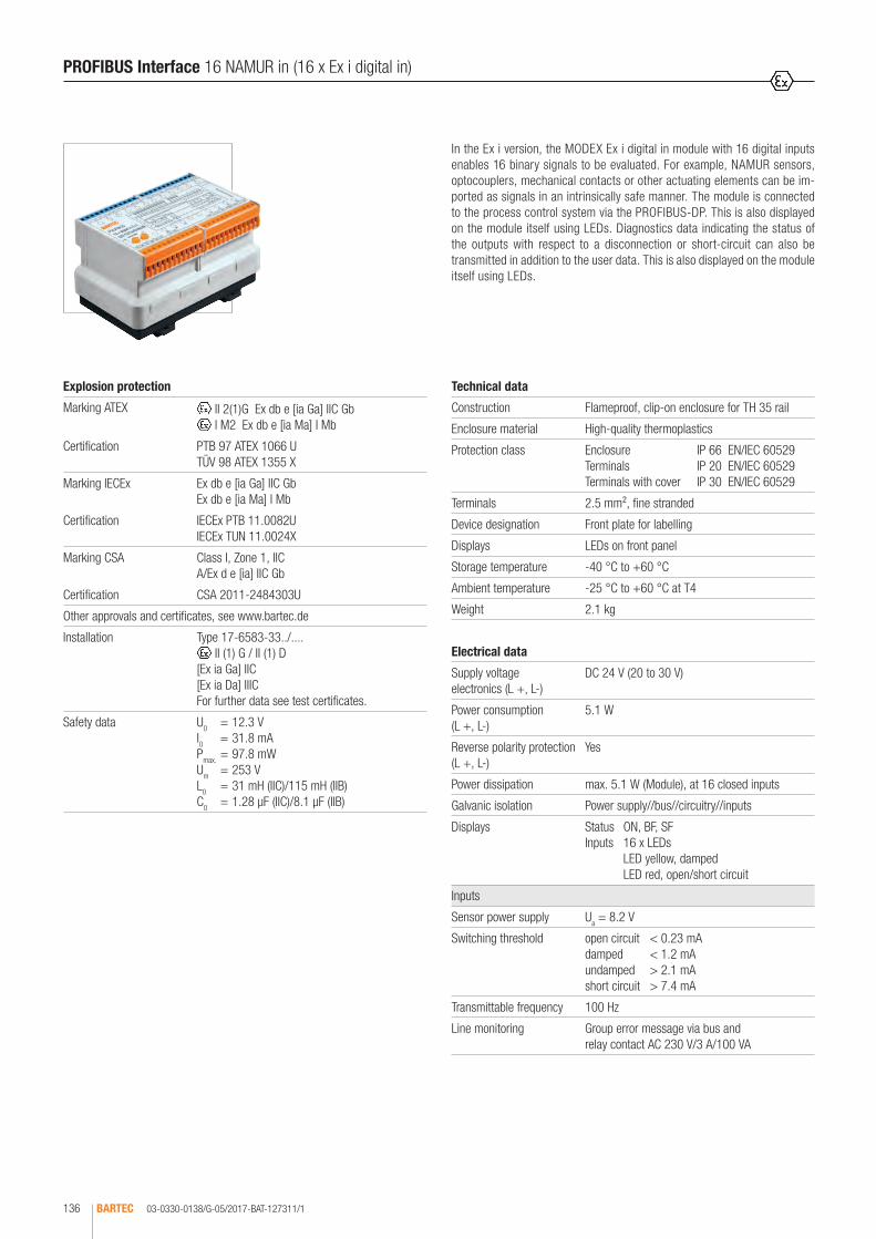
03-0330-0138/G-05/2017-BAT-127311/1BARTEC136
In the Ex i version, the MODEX Ex i digital in module with 16 digital inputs enables 16 binary signals to be evaluated. For example, NAMUR sensors, optocouplers, mechanical contacts or other actuating elements can be im-ported as signals in an intrinsically safe manner. The module is connected to the process control system via the PROFIBUS-DP. This is also displayed on the module itself using LEDs. Diagnostics data indicating the status of the outputs with respect to a disconnection or short-circuit can also be transmitted in addition to the user data. This is also displayed on the module itself using LEDs.
PROFIBUS Interface 16 NAMUR in (16 x Ex i digital in)
Technical data
Construction Flameproof, clip-on enclosure for TH 35 rail
Enclosure material High-quality thermoplastics
Protection class Enclosure IP 66 EN/IEC 60529 Terminals IP 20 EN/IEC 60529 Terminals with cover IP 30 EN/IEC 60529
Terminals 2.5 mm², fine stranded
Device designation Front plate for labelling
Displays LEDs on front panel
Storage temperature -40 °C to +60 °C
Ambient temperature -25 °C to +60 °C at T4
Weight 2.1 kg
Explosion protection
Marking ATEX II 2(1)G Ex db e [ia Ga] IIC Gb I M2 Ex db e [ia Ma] I Mb
Certification PTB 97 ATEX 1066 U TÜV 98 ATEX 1355 X
Marking IECEx Ex db e [ia Ga] IIC Gb Ex db e [ia Ma] I Mb
Certification IECEx PTB 11.0082U IECEx TUN 11.0024X
Marking CSA Class I, Zone 1, IIC A/Ex d e [ia] IIC Gb
Certification CSA 2011-2484303U
Other approvals and certificates, see www.bartec.de
Installation Type 17-6583-33../.... II (1) G / II (1) D
[Ex ia Ga] IIC [Ex ia Da] IIIC For further data see test certificates.
Safety data U0 = 12.3 V I0 = 31.8 mA Pmax. = 97.8 mW Um = 253 V L0 = 31 mH (IIC)/115 mH (IIB) C0 = 1.28 µF (IIC)/8.1 µF (IIB)
Electrical data
Supply voltage electronics (L +, L-)
DC 24 V (20 to 30 V)
Power consumption (L +, L-)
5.1 W
Reverse polarity protection (L +, L-)
Yes
Power dissipation max. 5.1 W (Module), at 16 closed inputs
Galvanic isolation Power supply//bus//circuitry//inputs
Displays Status ON, BF, SF Inputs 16 x LEDs LED yellow, damped LED red, open/short circuit
Inputs
Sensor power supply Ua = 8.2 V
Switching threshold open circuit < 0.23 mA damped < 1.2 mA undamped > 2.1 mA short circuit > 7.4 mA
Transmittable frequency 100 Hz
Line monitoring Group error message via bus and relay contact AC 230 V/3 A/100 VA

03-0330-0138/G-05/2017-BAT-127311/2 BARTEC 137
1
Status chart
Input Data bit Diagnostics bit
Type 07-7331-2303/0000 Type 07-7331-2303/1000Jumper
Open circuit/short circuit removed
Jumper Open circuit/short circuit
connected
damped 1 0 0 0
undamped 0 1 0 0
open circuit 1 0 1 0
short circuit 0 1 1 0B A
BUS
x x
Ex i
531 2 4 613 14 15 16 17 18 19 20 21 22 23 24
8 10 121197121098765432 111
ADDRESSx 10 x 1
1
6
9
4
1
6
9
4
302928272625SFBF 61NO
40 41 42 43 44 PA L- L+15 1314
3332
42 43 4425 26 27 28 29 30 3332
1 2 3 4 5 6 7 8 9 10 11 12
L+L-40 41
13 14 15 16 17 18 19 20 21 22 23 24
+ + + + + + + +
PA
PA
PA
.21.20
PA
PA 0 V 24 V
B/S
B A B A
91.2. .14
X4.16
.18.17.16.15.11 .12 X1.13.9 .10.5 .8.7.6.3 .4X1.1 .22
.19 .20 .21 .22 .23 .24
.24.23
.18.17.9.8.6.5.4.3.2X4.1
PROFIBUS16 x digital in Ex iDIN 19234/NAMUR
Wiring diagram/terminal assignment
PROFIBUS Interface 16 NAMUR in (16 x Ex i digital in)
Note
To disable open/short circuit monitoring, bridge terminals 40 and 41.
Use a 1 kΩ/10 kΩ resistive coupling element type 17-9Z62-0002 for open/short circuit monitoring during contact scan.
With 9 - 16 sensors also use external terminals.
Last bus module in system
Bridge A-AX (terminals 30, 33) Bridge B-BX (terminals 29, 32)
GSD file Download
BARX2903.gsd http://automation.bartec.de
Ordering information
Standard 07-7331-2303/0000
Inverted 07-7331-2303/1000
Technical data subject to change without notice.
102
96
Dimensions/mounting positions
170

03-0330-0139/E-05/2017-BAT-127312/1BARTEC138
In the Ex i version, the MODEX 8 x 4 to 20 mA module with 8 analogue inputs enables the supply and data logging of 8 analogue intrinsically safe two-wire transmitters. The input signal has 12-bit resolution and is transmitted with high interference resistance. The module is connected to the process control sys-tem via the PROFIBUS-DP. Coding rotary switches are available for addressing the module. Diagnostics data indicating the status of the outputs with respect to a disconnection or short-circuit can also be transmitted in addition to the user data. This is also displayed on the module itself using LEDs.
Technical data
Construction Flameproof, clip-on enclosure for TH 35 rail
Enclosure material High-quality thermoplastics
Protection class Electronic assembly IP 66 EN/IEC 60529 Terminals IP 20 EN/IEC 60529 Terminals with covers IP 30 EN/IEC 60529
Terminals 2.5 mm2, fine stranded
Device designation Front plate for labelling
Displays LEDs on front panel
Storage temperature -40 °C to +60 °C
Ambient temperature -25 °C to +60 °C at T4
Weight 2.1 kg
Explosion protection
Marking ATEX II 2(1)G Ex db e [ia Ga] IIC Gb I M2 Ex db e [ia Ma] I Mb
Certification PTB 97 ATEX 1066 U TÜV 98 ATEX 1367 X
Marking IECEx Ex db e [ia Ga] IIC Gb Ex db e [ia Ma] I Mb
Certification IECEx PTB 11.0082U IECEx TUN 11.0032X
Marking CSA Class I, Zone 1, IIC A/Ex d e [ia] IIC Gb
Certification CSA 2011-2484303U
Other approvals and certificates, see www.bartec.de
Installation Type 17-6583-34../.... II (1) G / II (1) D
[Ex ia Ga] IIC [Ex ia Da] IIIC For further data see test certificates.
Safety data U0 = 26 V Um = 253 V P0 = 549 mW I0 = 84.3 mA L0 = 5.3 mH (IIC)/20 mH (IIB) C0 = 99 nF (IIC)/770 nF (IIB) P = 549 mW
PROFIBUS Interface 8 x 4 to 20 mA in Ex i
Electrical data
Supply voltage electronics (L +, L-)
DC 24 V (20 to 30 V)
Power consumption (L +, L-)
7.6 W
Reverse polarity protection (L +, L-)
Yes
Power dissipation max. 5.1 W (Module)
Galvanic isolation Power supply//bus//circuitry//inputs
Bus interface RS485 with screw terminals
Displays Bus status ON, BF, SF Inputs 8 x LEDs LED yellow, sensor active LED red, open circuit/short circuit
Inputs
Transmitter power supply Ua = 15 V at 20 mA
Signal range 24 to 20 mA24 mA = 655 dec.20 mA = 3276 dec.
Transmission range 0 to 25 mA
Input resistance R i = 100 Ω
Conversion time < 1 ms
Resolution 12 bit
Precision ± 0.2 % (with shielded cable)
Line monitoring Group error message via bus and relay contact AC 230 V/3 A/100 V

03-0330-0139/E-05/2017-BAT-127312/2 BARTEC 139
1
Wiring diagram/terminal assignment
BF
4 6
SF
8751 2 3
9
4
1
ADDRESS66 4
9
x 1
1
x 10 PA
L+4443424140
B/S
25 26 27 28 29 30
-+ -+ -+ -+ -+ -+ - -+
24 V
BUS
ABABAB
32 33
8 x 4 - 20 mA
1
Ex i
16
7 8
15141312111098765432
531 2 4 6
25 26 27 28 29 30 32 33
1 2 3 4 5 6 7 8 9 10 11 12 13 14 15 16
40 41 42 43 44 PA L- L+
+
0 V
ON
PA L-
x x
PA
PA
PA
91.2. .14
.17
.18.17.16.15.11 .12 X1.13.9 .10.5 .8.7.6.3 .4X1.1 .21.20
.18X4.16.9.8.6.5.4.3.2X4.1 .19 .20 .21 .22 .23 .24
.24.23.22
PROFIBUS8 x 4 ... 20 mATransmitter in
Note
To disable open/short circuit monitoring, bridge terminals 40 and 41
Last bus module in system
Bridge A-AX (terminals 30, 33) Bridge B-BX (terminals 29, 32)
GSD file Download
BARX2902.gsd http://automation.bartec.de
Ordering information
PROFIBUS Interface 8 x 4 to 20 mA in Ex i 07-7331-2304/0000
Technical data subject to change without notice.
102
96
Dimensions/mounting positions
170
PROFIBUS Interface 8 x 4 to 20 mA in Ex i

03-0330-0283/E-10/2017-BAT-207713/1BARTEC140
Explosion protection
Marking ATEX II 2(1)G Ex db e IIC Gb I M2 Ex db e I Mb
Certification PTB 97 ATEX 1066 U
Marking IECEx Ex db e IIC Gb Ex db e I Mb
Certification IECEx PTB 11.0082U
Marking CSA Class I Zone 1 IIC A/Ex d e IIC Gb
Certification CSA 2011-2484303U
Other approvals and certificates, see www.bartec.de
In the Ex e version, the MODEX 8 x 4 to 20 mA module with 8 analogue inputs enables 8 analogue active signals to be fed in. The input signal has 12-bit resolution and is transmitted with high interference resistance. The module is connected to the process control system via the PROFIBUS-DP. Coding rotary switches are available for addressing the module. Diagnostics data indicating the status of the outputs with respect to a disconnection or short-circuit can also be transmitted in addition to the user data. This is also displayed on the module itself using LEDs.
Technical data
Construction Flameproof, clip-on enclosure for TH 35 rail
Enclosure material High-quality thermoplastic
Protection class Electronic assembly IP 66 EN/IEC 60529 Terminals IP 20 EN/IEC 60529 Terminals with covers IP 30 EN/IEC 60529
Terminals 2.5 mm², fine stranded
Device designation Front plate for labelling
Displays LEDs on front panel
Storage temperature -40 °C to +60 °C
Ambient temperature -25 °C to +60 °C at T4
Weight 2.1 kg
PROFIBUS Interface 8 x 4 to 20 mA in passive Ex e
Electrical data
Supply voltage electronics (L +, L-)
DC 24 V (20 to 30 V)
Power consumption (L +, L-)
3.8 W
Reverse polarity protection (L +, L-)
Yes
Power dissipation max. 4.1 W (Module)
Galvanic isolation Power supply//bus//circuitry//inputs
Bus interface RS485 with screw terminals
Displays Bus status ON, BF, SF Inputs 8 x LEDs LED yellow, sensor active LED red, open circuit/short circuit
Inputs
Signal range 24 to 20 mA24 mA = 655 dec.20 mA = 3276 dec.
Transmission range 0 to 25 mA
Input resistance R i = 100 Ω
Conversion time < 1 ms
Resolution 12 bit
Precision ± 0.2 % (with shielded cable)
Line monitoring Group error message via bus and relay contact AC 230 V/3 A/100 V
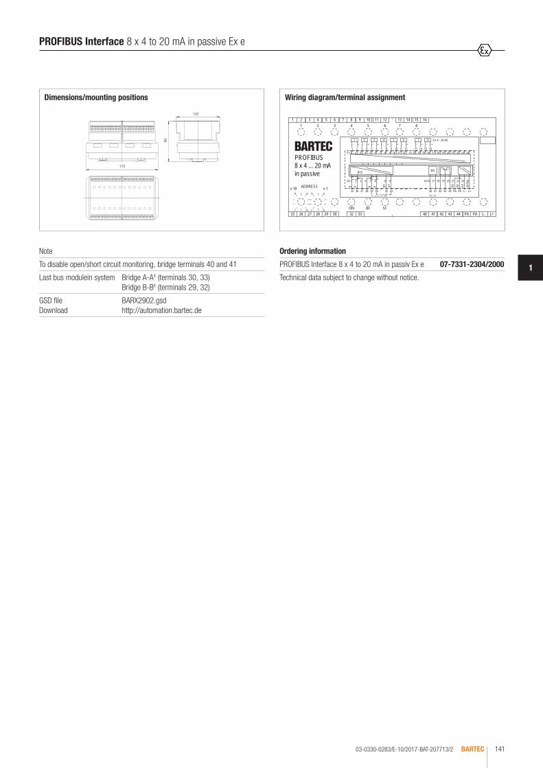
03-0330-0283/E-10/2017-BAT-207713/2 BARTEC 141
1
BF
4 6
SF
8751 2 3
9
4
1
ADDRESS66 4
9
x 1
1
x 10 PA
L+4443424140
B/S
25 26 27 28 29 30
+- +- +- +- +- +- + +-
24 V
BUS
ABABAB
32 33
8 x 4 - 20 mA
611
7 8
15141312111098765432
531 2 4 6
25 26 27 28 29 30 32 33
1 2 3 4 5 6 7 8 9 10 11 12 13 14 15 16
40 41 42 43 44 PA L- L+
-
0 V
ON
PA L-
x x PA
PA
PA
91.2. .14
.17
.18.17.16.15.11 .12 X1.13.9 .10.5 .8.7.6.3 .4X1.1 .21.20
.18X4.16.9.8.6.5.4.3.2X4.1 .19 .20 .21 .22 .23 .24
.24.23.22
PROFIBUS8 x 4 ... 20 mAin passive
Wiring diagram/terminal assignment
Note
To disable open/short circuit monitoring, bridge terminals 40 and 41
Last bus modulein system Bridge A-AX (terminals 30, 33) Bridge B-BX (terminals 29, 32)
GSD file Download
BARX2902.gsd http://automation.bartec.de
Ordering information
PROFIBUS Interface 8 x 4 to 20 mA in passiv Ex e 07-7331-2304/2000
Technical data subject to change without notice.
102
96
Dimensions/mounting positions
170
PROFIBUS Interface 8 x 4 to 20 mA in passive Ex e

03-0330-0337/D-10/2017-BAT-220219/1BARTEC142
In the Ex e version, the MODEX 8 x 4 to 20 mA module with 8 analogue inputs enables 8 analogue signals to be fed in. For example, two-wire trans-mitters can be imported as signals. The input signal has 12-bit resolution and is transmitted with high interference resistance. The module is connected to the process control system via the PROFIBUS-DP. Coding rotary switches are available for addressing the module. Diagnostics data indicating the status of the outputs with respect to a disconnection or short-circuit can also be transmitted in addition to the user data. This is also displayed on the module itself using LEDs.
Technical data
Construction Flameproof, clip-on enclosure for TH 35 rail
Enclosure material High-quality thermoplastics
Protection class Electronic assembly IP 66 EN/IEC 60529 Terminals IP 20 EN/IEC 60529 Terminals with cover IP 30 EN/IEC 60529
Terminals 2.5 mm², fine stranded
Device designation Front plate for labelling
Displays LEDs on front panel
Storage temperature -40 °C to +60 °C
Ambient temperature -25 °C to +60 °C at T4
Weight 2.1 kg
Explosion protection
Marking ATEX II 2(1)G Ex db e IIC Gb I M2 Ex db e I Mb
Certification PTB 97 ATEX 1066 U
Marking IECEx Ex db e IIC Gb Ex db e I Mb
Certification IECEx PTB 11.0082U
Marking CSA Class I Zone 1 IIC A/Ex d e IIC Gb
Certification CSA 2011-2484303U
Other approvals and certificates, see www.bartec.de
PROFIBUS Interface 8 x 4 to 20 mA 8 Transmitter in Ex e
Electrical data
Supply voltage electronics (L +, L-)
DC 24 V (20 to 30 V)
Power consumption (L +, L-)
7.6 W
Reverse polarity protection (L +, L-)
Yes
Power dissipation max. 5.1 W (Module)
Galvanic isolation Power supply//bus//circuitry//inputs
Bus interface RS485 with screw terminals
Displays Bus status ON, BF, SF Inputs 8 x LEDs LED yellow, sensor active LED red, open circuit/short circuit
Inputs
Transmission range 0 to 25 mA
Signal range 24 to 20 mA24 mA = 655 dec.20 mA = 3276 dec.
Transmission range 0 to 25 mA
Input resistance R i = 100 Ω
Conversion time < 1 ms
Resolution 12 bit
Precision ± 0.2 % (with shielded cable)
Line monitoring Group error message via bus and relay contact AC 230 V/3 A/100 V

03-0330-0337/D-10/2017-BAT-220219/2 BARTEC 143
1
BF
4 6
SF
8751 2 3
9
4
1
ADDRESS66 4
9
x 1
1
x 10 PA
L+4443424140
B/S
25 26 27 28 29 30
-+ -+ -+ -+ -+ -+ - -+
24 V
BUS
ABABAB
32 33
8 x 4 - 20 mA
611
7 8
15141312111098765432
531 2 4 6
25 26 27 28 29 30 32 33
1 2 3 4 5 6 7 8 9 10 11 12 13 14 15 16
40 41 42 43 44 PA L- L+
+
0 V
ON
PA L-
x x
PA
PA
PA
91.2. .14
.17
.18.17.16.15.11 .12 X1.13.9 .10.5 .8.7.6.3 .4X1.1 .21.20
.18X4.16.9.8.6.5.4.3.2X4.1 .19 .20 .21 .22 .23 .24
.24.23.22PROFIBUS8 x 4 ... 20 mATransmitter in(aktive)
Wiring diagram/terminal assignment
Note
Bridge open circuit/short circuit terminals 40 and 41 to disable open/short circuit monitoring.
Last bus module in system
Bridge A-AX (terminals 30, 33) Bridge B-BX (terminals 29, 32)
GSD file Download
BARX2902.gsd http://automation.bartec.de
Ordering information
PROFIBUS Interface 8 x 4 to 20 mA, 8 transmitter in Ex e
07-7331-2304/3000
Technical data subject to change without notice.
102
96
Dimensions/mounting positions
170
PROFIBUS Interface 8 x 4 to 20 mA 8 Transmitter in Ex e
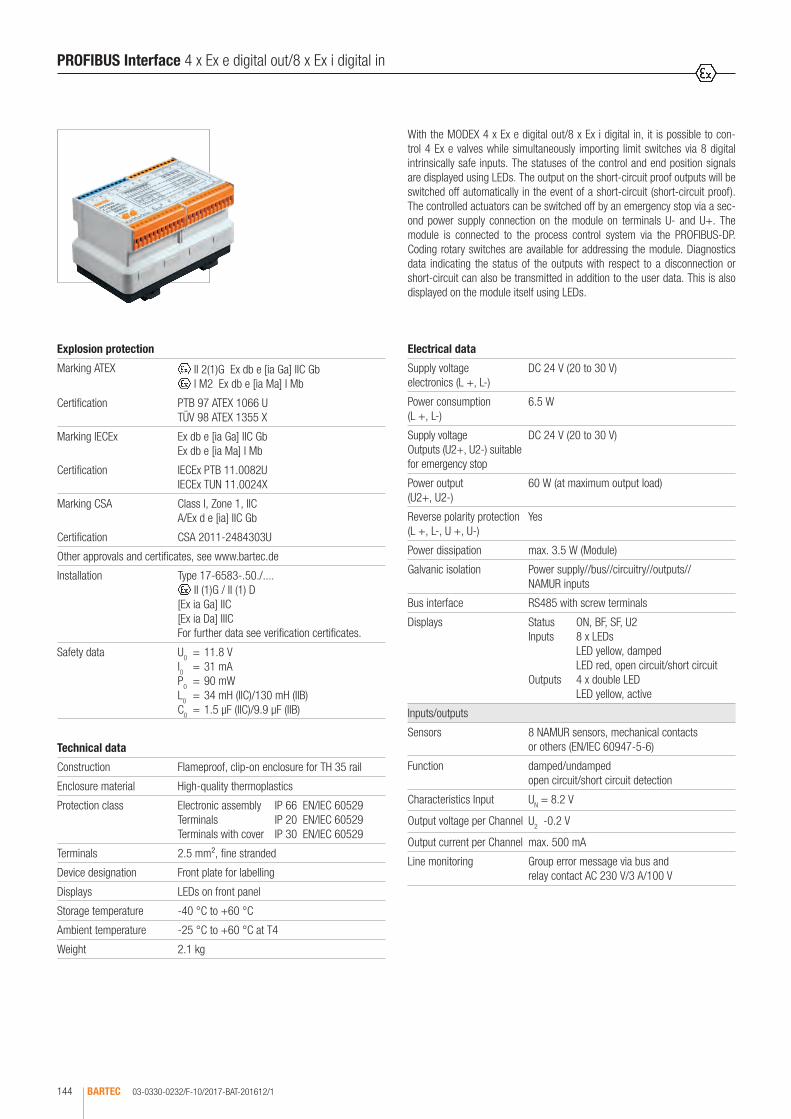
03-0330-0232/F-10/2017-BAT-201612/1BARTEC144
With the MODEX 4 x Ex e digital out/8 x Ex i digital in, it is possible to con-trol 4 Ex e valves while simultaneously importing limit switches via 8 digital intrinsically safe inputs. The statuses of the control and end position signals are displayed using LEDs. The output on the short-circuit proof outputs will be switched off automatically in the event of a short-circuit (short-circuit proof).The controlled actuators can be switched off by an emergency stop via a sec-ond power supply connection on the module on terminals U- and U+. The module is connected to the process control system via the PROFIBUS-DP. Coding rotary switches are available for addressing the module. Diagnostics data indicating the status of the outputs with respect to a disconnection or short-circuit can also be transmitted in addition to the user data. This is also displayed on the module itself using LEDs.
Technical data
Construction Flameproof, clip-on enclosure for TH 35 rail
Enclosure material High-quality thermoplastics
Protection class Electronic assembly IP 66 EN/IEC 60529 Terminals IP 20 EN/IEC 60529 Terminals with cover IP 30 EN/IEC 60529
Terminals 2.5 mm², fine stranded
Device designation Front plate for labelling
Displays LEDs on front panel
Storage temperature -40 °C to +60 °C
Ambient temperature -25 °C to +60 °C at T4
Weight 2.1 kg
Explosion protection
Marking ATEX II 2(1)G Ex db e [ia Ga] IIC Gb I M2 Ex db e [ia Ma] I Mb
Certification PTB 97 ATEX 1066 U TÜV 98 ATEX 1355 X
Marking IECEx Ex db e [ia Ga] IIC Gb Ex db e [ia Ma] I Mb
Certification IECEx PTB 11.0082U IECEx TUN 11.0024X
Marking CSA Class I, Zone 1, IIC A/Ex d e [ia] IIC Gb
Certification CSA 2011-2484303U
Other approvals and certificates, see www.bartec.de
Installation Type 17-6583-.50./.... II (1)G / II (1) D
[Ex ia Ga] IIC [Ex ia Da] IIIC For further data see verification certificates.
Safety data U0 = 11.8 V I0 = 31 mA P0 = 90 mW L0 = 34 mH (IIC)/130 mH (IIB) C0 = 1.5 µF (IIC)/9.9 µF (IIB)
PROFIBUS Interface 4 x Ex e digital out/8 x Ex i digital in
Electrical data
Supply voltage electronics (L +, L-)
DC 24 V (20 to 30 V)
Power consumption (L +, L-)
6.5 W
Supply voltage Outputs (U2+, U2-) suitable for emergency stop
DC 24 V (20 to 30 V)
Power output (U2+, U2-)
60 W (at maximum output load)
Reverse polarity protection (L +, L-, U +, U-)
Yes
Power dissipation max. 3.5 W (Module)
Galvanic isolation Power supply//bus//circuitry//outputs// NAMUR inputs
Bus interface RS485 with screw terminals
Displays Status ON, BF, SF, U2 Inputs 8 x LEDs LED yellow, damped LED red, open circuit/short circuit Outputs 4 x double LED LED yellow, active
Inputs/outputs
Sensors 8 NAMUR sensors, mechanical contacts or others (EN/IEC 60947-5-6)
Function damped/undamped open circuit/short circuit detection
Characteristics Input UN = 8.2 V
Output voltage per Channel U2 -0.2 V
Output current per Channel max. 500 mA
Line monitoring Group error message via bus and relay contact AC 230 V/3 A/100 V
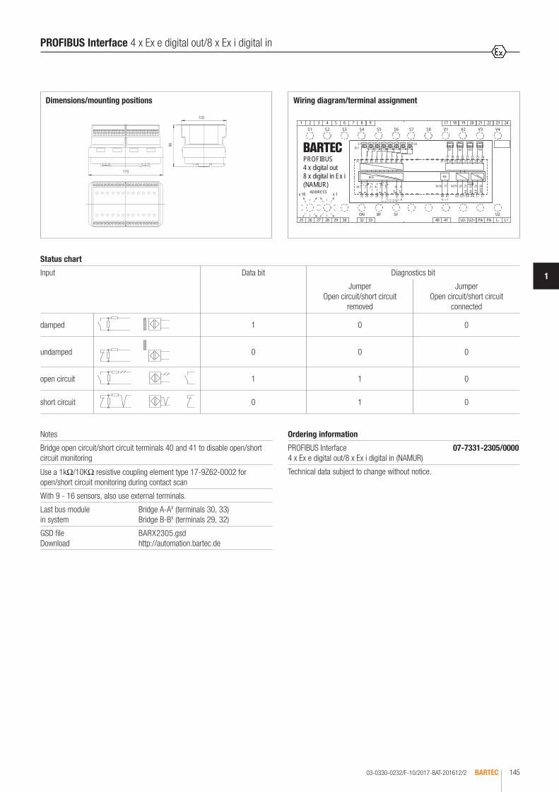
03-0330-0232/F-10/2017-BAT-201612/2 BARTEC 145
1
V3 V4V2
S1 S8
U2
S6S4S2S1 S3 S517 18 19 20 21 22 23 24
PA 0 V 24 V
B/S
ADDRESSx 10 x 1
1
6
9
4
1
6
9
4
SF
S7 V1 V3 V4V2S8
Ex i V1
ON BF33
9
32
87
30
6
29
5
28
4
27
3
26
2
25
1
U2- U2+40 41 PA L- L+
AABAB
BUS
B
PA
+-+-+-+-+
23 24222120191817987654321
L+L-U2+U2-41403332302928272625
PA
PA
PA
x x
X1.1 .2 .3 .4 .5 .6 .7 .8 .9
X4.1 .2 .3 .4 .5 .6 .8 .9
X1.17 .18 .19 .20 .21
X4.16 .17 X4.19 .20 .21 .22 .23 .24
.22 .23 .24PROFIBUS4 x digital out8 x digital in Ex i(NAMUR)
Status chart
Input Data bit Diagnostics bit
Jumper Open circuit/short circuit
removed
Jumper Open circuit/short circuit
connected
damped 1 0 0
undamped 0 0 0
open circuit 1 1 0
short circuit 0 1 0
Wiring diagram/terminal assignment
Notes
Bridge open circuit/short circuit terminals 40 and 41 to disable open/short circuit monitoring
Use a 1kΩ/10KΩ resistive coupling element type 17-9Z62-0002 for open/short circuit monitoring during contact scan
With 9 - 16 sensors, also use external terminals.
Last bus module in system
Bridge A-AX (terminals 30, 33) Bridge B-BX (terminals 29, 32)
GSD file Download
BARX2305.gsd http://automation.bartec.de
Ordering information
PROFIBUS Interface 4 x Ex e digital out/8 x Ex i digital in (NAMUR)
07-7331-2305/0000
Technical data subject to change without notice.
102
96
Dimensions/mounting positions
170
PROFIBUS Interface 4 x Ex e digital out/8 x Ex i digital in

03-0330-0140/F-05/2017-BAT-127486/1BARTEC146
In the Ex i or Ex e version, the MODEX 8 x 4 to 20 mA module can control various actuators depending on the model using 8 analogue short-circuit proof outputs. The controlled actuators can be switched off by an emergency stop via a second power supply connection on the module on terminals U- and U+.The module is connected to the process control system via the PROFIBUS-DP. Coding rotary switches are available for addressing the module. Diagnostics data indicating the status of the outputs with respect to a disconnection or short-circuit can also be transmitted in addition to the user data. This is also displayed on the module itself using LEDs.
Technical data
Construction Flameproof, clip-on enclosure for TH 35 rail
Enclosure material High-quality thermoplastics
Protection class Electronic assembly IP 66 EN/IEC 60529 Terminals IP 20 EN/IEC 60529 Terminals with covers IP 30 EN/IEC 60529
Terminals 2.5 mm2, fine stranded
Device designation Front plate for labelling
Displays LEDs on front panel
Storage temperature -40 °C to +60 °C
Ambient temperature -25 °C to +60 °C at T4
Weight 2.1 kg
Explosion protection Ex i
Marking ATEX II 2(1)G Ex db e [ia Ga] IIC Gb I M2 Ex db e [ia Ma] I Mb
Certification PTB 97 ATEX 1066 U TÜV 99 ATEX 1426
Marking IECEx Ex db e [ia Ga] IIC Gb Ex db e [ia Ma] I Mb
Certification IECEx PTB 11.0082U IECEx TUN 11.0033X
Marking CSA Class I, Zone 1, IIC A/Ex d e [ia] IIC Gb
Certification CSA 2011-2484303U
Installation Type 17-6583-3600 II (1)G / II (1)D
[Ex ia Ga] IIC [Ex ia Da] IIIC For further data see test certificates.
Safety data U0 = 21.4 V I0 = 93.9 mA P0 = 503 mW C0 = 176 nF (IIC)/1.2 µF (IIB) L0 = 3.4 mH (IIC)/13.9 mH (IIB) Um = 253 V
Explosion protection Ex e
Marking ATEX II 2G Ex db e IIC Gb I M2 Ex db e I Mb
Certification PTB 97 ATEX 1066 U
Marking IECEx Ex db e IIC Gb Ex db e I Mb
Certification IECEx PTB 11.0082U
Marking CSA Class I, Zone 1, IIC A/Ex d e IIC Gb
Certification CSA 2011-2484303U
Other approvals and certificates, see www.bartec.de
PROFIBUS Interface 8 x 4 to 20 mA out Ex i/Ex e
Electrical data
Supply voltage electronics (L +, L-)
DC 24 V (20 to 30 V)
Power consumption (L +, L-)
1.8 W
Supply voltage Outputs (U +, U-) suitable for emergency stop
DC 24 V (20 to 30 V)
Power consumption max. 5.7 W
Reverse polarity protection (L +, L-, U+, U-)
Yes
Power dissipation max. 7.5 W (Module)
Galvanic isolation Power supply//bus//circuitry//outputs//
Bus interface RS485 with screw terminals
Displays Status ON, BF, SF, UB2Outputs 8 x LEDs LED yellow, output ok LED red, short circuit
Outputs
Signal range 4 to 20 mA 4 mA = 0 dec.20 mA = 4096 dec.
Resolution 12 bit
Quantising 3.91 µA/LSB
Load 0 to 500 Ω
Basic error at TU = 25 °C ± 0.2 %
Linearity ± 0.2 %
Line monitoring Group error message via bus

03-0330-0140/F-05/2017-BAT-127486/2 BARTEC 147
1
UB2
x x
1 2 3 4 5 6 7 8 9 10 11 12 13 14 15 1631 2 4 5 6 7 8
ADDRESSx 10 x 1
25 26 27 28 29 30 3332SFBFON
PA L-40 41 U- U+ L+
1
6
9
4
1
6
9
4
2 3 4 5 6
L+L-PA
PA 0 V 24 V
B
40 41 U- U+25 26 27 28 29 30
+ - + - + - + -4
7 8+ -5
9 10+ -6
11 12+ -7
13 14+ -8
15 161
3332
B A B A B A
BUS
Am 02 - 4 x 8321
PA
PA
PA
X1.1 .2 .3 .4 .5 .6 .7 .8 .9 .10 .11
X4.1 .2 .3 .4 .5 .6 X4.8 .9
.12 X1.13 .14 .15 .16
X4.16 .17 X4.19 .20 .21 .22 .23 .24
PROFIBUS8 x analog out
Wiring diagram/terminal assignment
Note
To disable open/short circuit monitoring, bridge terminals 40 and 41.
Last bus module in system
Bridge A-AX (terminals 30, 33) Bridge B-BX (terminals 29, 32)
GSD file Download
BARX2306.gsd http://automation.bartec.de
102
96
Dimensions/mounting positions
170
Ordering information
PROFIBUS Interface 8 x 4 to 20 mA out Ex i 07-7331-2306/0000
PROFIBUS Interface 8 x 4 to 20 mA out Ex e 07-7331-2306/1000
Technical data subject to change without notice.
PROFIBUS Interface 8 x 4 to 20 mA out Ex i/Ex e
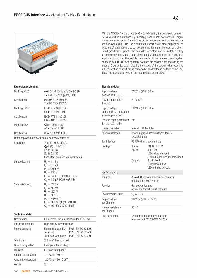
03-0330-0146/F-10/2017-BAT-127597/1BARTEC148
With the MODEX 4 x digital out Ex i/8 x Ex i digital in, it is possible to control 4 Ex i valves while simultaneously importing NAMUR limit switches via 8 digital intrinsically safe inputs. The statuses of the control and end position signals are displayed using LEDs. The output on the short-circuit proof outputs will be switched off automatically by temperature monitoring in the event of a short-circuit (short-circuit proof). The controlled actuators can be switched off by an emergency stop via a second power supply connection on the module on terminals U- and U+. The module is connected to the process control system via the PROFIBUS-DP. Coding rotary switches are available for addressing the module. Diagnostics data indicating the status of the outputs with respect to a disconnection or short-circuit can also be transmitted in addition to the user data. This is also displayed on the module itself using LEDs.
Technical data
Construction Flameproof, clip-on enclosure for TS 35 rail
Enclosure material High-quality thermoplastics
Protection class Electronic assembly IP 66 EN/IEC 60529 Terminals IP 20 EN/IEC 60529 Terminals with cover IP 30 EN/IEC 60529
Terminals 2.5 mm², fine stranded
Device designation Front plate for labelling
Displays LEDs on front panel
Storage temperature -40 °C to +60 °C
Ambient temperature -25 °C to +60 °C at T4
Weight 2.1 kg
Explosion protection
Marking ATEX II 2(1)G Ex db e [ia Ga] IIC Gb I M2 Ex db e [ia Ma] I Mb
Certification PTB 97 ATEX 1066 U TÜV 98 ATEX 1355 X
Marking IECEx Ex db e [ia Ga] IIC Gb Ex db e [ia Ma] I Mb
Certification IECEx PTB 11.0082U IECEx TUN 11.0024X
Marking CSA Class I Zone 1 IIC A/Ex d e [ia] IIC Gb
Certification CSA 2011-2484303U
Other approvals and certificates, see www.bartec.de
Installation Type 17-6583-.51./.... II (1) G / II (1) D
[Ex ia Ga] IIC [Ex ia Da] IIIC For further data see test certificates.
Safety data (in) U0 = 11.8 V I0 = 31 mA P0 = 90 mW Um = 253 V L0 = 34 mH (IIC)/130 mH (IIB) C0 = 1.5 µF (IIC)/9.9 µF (IIB)
Satety data (out) U0 = 26.8 V I0 = 97 mA Um = 253 V Ri = 301 Ω P0 = 650 mW L0 = 3.9 mH (IIC)/15 mH (IIB) C0 = 92 nF (IIC)/720 nF (IIB)
PROFIBUS Interface 4 x digital out Ex i/8 x Ex i digital in
Electrical data
Supply voltage electronics (L +, L-)
DC 24 V (20 to 30 V)
Power consumption (L +, L-)
P = 6.5 W
Supply voltage Outputs (U +, U-) suitable for emergency stop
DC 24 V (20 to 30 V)
Reverse polarity protection (L +, L-, U2+, U2-)
Yes
Power dissipation max. 4.5 W (Module)
Galvanic isolation Power supply//bus//circuitry//outputs// NAMUR inputs
Bus interface RS485 with screw terminals
Displays Status ON, BF, SF, U2 Inputs 8 x LEDs LED yellow, damped LED red, open circuit/short circuit Outputs 4 x double LED LED yellow, active LED red, short circuit
Inputs/outputs
Sensors 8 NAMUR sensors, mechanical contacts or others (EN 60947-5-6)
Function damped/undamped open circuit/short circuit detection
Characteristics Input UN = 8.2 V
Output voltage per Channel
DC 22 V (at U2 ≥ 24 V)
Internal resistance per Channel
301 Ω
Line monitoring Group error message via bus and relay contact AC 230 V/3 A/100 V

03-0330-0146/F-10/2017-BAT-127597/2 BARTEC 149
1
321
24
9 108
23
ADDRESSx 10 x 1
1
6
15764
22
11 12
21
22 23 24
Ex i V1
5
2010
33
9
32
87 19
x x PA
PA
PA
1
18
9
4
V2
ON BF
333225 26 27 28 29 30
11 17
13 14
V4Ex i
U2- U2+40 41 PA L- L+
ABABA
U2+ L+L-U2-
V1 V3 V4V2S8
16 17 18 19 20 21
V3
S1
+
30
6
29
5
28
4
27
3
26
2
25
1
- +
B
BUS
-
12
-
B/S
-+
PA
PA 0 V
SF
1413S7
6
9
4
+ +
4140
U2
S6
S8
S2S1 S3 S515 16
S4
24 V
X1.1 .2 .3 .4 .5 .6 .7 .8 .9 .10 .11
X4.1 .2 .3 .4 .5 .6 .8 .9
.12 X1.13 .14 .15 .16 .17 .18 .19 .20 .21
X4.16 .17 .18 .19 .20 .21 .22 .23 .24
.22 .23 .24PROFIBUS4 x digital out Ex i8 x digital in Ex i(NAMUR)
Status chart
Input Data bit Diagnostics bit
Jumper Open circuit/short circuit
removed
Jumper Open circuit/short circuit
connected
damped 1 0 0
undamped 0 0 0
open circuit 1 1 0
short circuit 0 1 0
Wiring diagram/terminal assignment
Notes
Bridge open circuit/short circuit terminals 40 and 41 to disable open/short circuit monitoring
Use a 1kΩ/10KΩ resistive coupling element type 17-9Z62-0002 for open/short circuit monitoring during contact scan
GSD file Download
BARX2305.gsd http://automation.bartec.de
Ordering information
PROFIBUS Interface 4 x digital out Ex i/8 x Ex i digital in (NAMUR)
07-7331-2305/1000
Technical data subject to change without notice.
102
96
Dimensions/mounting positions
170
PROFIBUS Interface 4 x digital out Ex i/8 x Ex i digital in

03-0330-0141/D-05/2017-BAT-127487/1BARTEC150
The MODEX RTD in Ex i module enables an intrinsically safe connection of 4 Pt100, Pt1000, resistors or potentiometers. The inputs are galvanically iso-lated from each other, from the power supply and from the bus. The module is connected to the process control system via the PROFIBUS-DP. This is also displayed on the module itself using LEDs. Diagnostics data indicating the sta-tus of the outputs with respect to a disconnection or short-circuit can also be transmitted in addition to the user data. This is also displayed on the module itself using LEDs.
PROFIBUS Interface 4 x RTD in Ex i
Technical data
Construction Flameproof, clip-on enclosure for TH 35 rail
Enclosure material High-quality thermoplastic
Protection class Enclosure IP 66 EN/IEC 60529 Terminals IP 20 EN/IEC 60529 Terminals with cover IP 30 EN/IEC 60529
Terminals 2,5 mm², fine stranded
Device designation Front plate for labelling
Displays LEDs on front panel
Storage temperature -40 °C to +60 °C
Ambient temperature -25 °C to +60 °C at T4
Weight 2.1 kg
Explosion protection
Marking ATEX II 2(1)G Ex db e [ia Ga] IIC/IIB Gb I M2 Ex db e [ia Ma] I Mb
Certification PTB 97 ATEX 1066 U TÜV 01 ATEX 1668
Marking IECEx Ex db e [ia Ga] IIC/IIB Gb Ex db e [ia Ma] I Mb
Certification IECEx PTB 11.0082U IECEx TUN 11.0028X
Marking CSA Class I, Zone 1, IIC A/Ex d e [ia] IIC Gb
Certification CSA 2011-2484303U
Other approvals and certificates, see www.bartec.de
Installation Type 17-6583-.7../.... II (1)G / II (1)D
[Ex ia Ga] IIC/IIB [Ex ia Da] IIIC/IIIB For further data see test certificates.
Safety data U0 = 7.2 V Um = 253 V I0 = 6 mA P0 = 11 mW L0 = 25 mH (IIC)/50 mH (IIB) C0 = 1.1 µF (IIC)/5.7 µF (IIB)
Electrical data
Supply voltage electronics (L +, L-)
DC 24 V (20 to 30 V)
Power consumption (L +, L-)
4 W
Reverse polarity protection (L +, L-, U+, U-)
Yes
Power dissipation max. 4 W (Module)
Galvanic isolation Power supply//bus//circuitry//inputs (also to each other)
Bus interface RS485 with screw terminals
Displays Status ON, BF, SF,Outputs 8 x LEDs LED yellow, output ok LED red, open circuit/short circuit
Inputs
Sensor power 200 µA
Measuring range Temperature (Pt100, Pt1000) -150 °C to +850 °CPotentiometer 500 Ω to 5 kΩResistor 0 Ω to 5 kΩ
Displays Temperature -1500 to 8500 (dec.)Potentiometer 0000 to 1000 (dec. 0 to 100 %)Resistor 0000 to 5000 (dec.)
Line resistance R ≤ 50 Ω (3-wire)
Precision ± 0.2 % (with shielded cable)
Temperature drift 0.05 %/10 K
Line monitoring Group error message via bus

03-0330-0141/D-05/2017-BAT-127487/2 BARTEC 151
1
Operating modes Conversion time
4 x Pt100 380 ms (*1) 320 ms (*2)
4 x Pt1000 380 ms (*1) 320 ms (*2)
4 x Potentiometer 80 ms (*3)
4 x Resistor 80 ms (*3)
2 x Pt100 (Channel 1 and 2); 2 x Potentiometer (Channel 3 and 4)
380 ms (*1) 320 ms (*2)
2 x Pt100 (Channel 1 and 2); 2 x Resistor (Channel 3 and 4)
380 ms (*1) 320 ms (*2)
2 x Pt1000 (Channel 1 and 2); 2 x Potentiometer (Channel 3 and 4)
380 ms (*1) 320 ms (*2)
2 x Pt1000 (Channel 1 and 2); 2 x Resistor (Channel 3 and 4)
380 ms (*1) 320 ms (*2)
all values 0 (dec.)
all values 32767 (dec.)
(*1) Filter set to 50 Hz(*2) Filter set to 60 Hz(*3) Filt fixed at 250 Hz
.24
.11 .12
X4.21
.4.2
.8
9.3.
ADDRESSx 1x 10
4 6
9191
64
33323029282726SFBFON
25
432111098765432
11
PA
PA
L+
X1.1
.2 .3
.8
.4
.10.6
.22 32.9.X4.1
.5
.5
.7
.6
PA
1 3 6542321 54 6
12
98797 8
Example
PA L- L+
L-PA
24 V
10 11 12
0 VPAx x ABAA BB
3332302928272625
PROFIBUSRTD in
Wiring diagram/terminal assignment
PROFIBUS Interface 4 x RTD in Ex i
Note
Last bus module in system
Bridge A-AX (Terminals 30, 33) Bridge B-BX (Terminals 29, 32)
GSD file Download
BARX2307.gsd http://automation.bartec.de
Ordering information
PROFIBUS Interface 4 x RTD in Ex i 07-7331-2307/0000
Technical data subject to change without notice.
102
96
Dimensions/mounting positions
170

03-0330-0142/E-05/2017-BAT-127488/1BARTEC152
In the Ex e version, the MODEX 8 relay out module can activate various actu-ators using 8 outputs. It is possible, for example, to directly activate encapsu-lated solenoid valves, indicator lamps or other certified consumers up to 6 A. The module is connected to the process control system via the PROFIBUS-DP. Coding rotary switches are available for addressing the module.
PROFIBUS Interface 8 x relay out Ex e
Technical data
Construction Flameproof, clip-on enclosure for TH 35 rail
Enclosure material High-quality thermoplastics
Protection class Electronic assembly IP 66 EN/IEC 60529 Terminals IP 20 EN/IEC 60529 Terminals with cover IP 30 EN/IEC 60529
Terminals 2.5 mm², fine stranded
Device designation Front plate for labelling
Displays LEDs on front panel
Storage temperature -40 °C to +60 °C
Ambient temperature -25 °C to +60 °C at T4
Weight 2.1 kg
Explosion protection
Marking ATEX II 2(1)G Ex db e IIC Gb I M2 Ex db e I Mb
Certification PTB 97 ATEX 1066 U
Marking IECEx Ex db e IIC Gb Ex db e I Mb
Certification IECEx PTB 11.0082U
Marking CSA Class I, Zone 1, IIC A/Ex d e IIC Gb
Certification CSA 2011-2484303U
Other approvals and certificates, see www.bartec.de
Electrical data
Supply voltage electronics (L +, L-)
DC 24 V (20 to 30 V)
Power consumption (L +, L-)
2.7 W
Reverse polarity protection (L+, L-)
Yes
Power dissipation max. 6 W (Module)
Galvanic isolation Power supply//bus//circuitry//outputs
Bus interface RS485 with screw terminals
Displays Status ON, BFOutputs 8 x LED yellow, active
Outputs
Power dissipation per Channel
max. 0.4 W
Output relay 1 changeover contact
UA Imax
AC 250 V (max.) 6.0 A cos ϕ = 1
DC 100 V 0.5 A
ohmic load
DC 160 V 1.0 A
DC 130 V 6.0 A
DC 115 V 6.0 A
Mechanical service life 10 million switching cycles

03-0330-0142/E-05/2017-BAT-127488/2 BARTEC 153
1
PROFIBUS Interface 8 x relay out Ex e
6421 3 515 16 17 18 19 20 21 22 23 2412
ADDRESSx 10 x 1
1
6
9
4
1
6
9
4
14137 8
ON BF
1110
33
9
32
87
30
6
29
5
28
4
27
3
26
2
25
1
PA L- L+
13 14 15432 5 6 7 8 9 10 11 12
1 2 3 4 5 6 7 8
2423222120191817611
8 xRelais
L+L-PA
PA 0 V 24 V
25 26 27 28 29 30 333231
B A B A
BUS
B Ax x
PA
PA
PA
PROFIBUS8 x Relais out
Ordering information
PROFIBUS Interface 8 x relay out Ex e 07-7331-2308/0000
Technical data subject to change without notice.
Wiring diagram/terminal assignment
Note
Last bus module in system
Bridge A-AX (terminals 30, 33) Bridge B-BX (terminals 29, 32)
GSD file Download
BARX2308.gsd http://automation.bartec.de
102
96
Dimensions/mounting positions
170

03-0330-0278/E-10/2017-BAT-203185/1BARTEC154
In the Ex i version, the MODEX 8 relay out module can activate various actua-tors using 8 outputs. It is possible, for example, to directly activate intrinsically safe solenoid valves or other intrinsically safe circuits. The module is connec-ted to the process control system via the PROFIBUS-DP. Coding rotary switches are available for addressing the module.
PROFIBUS Interface 8 x relay out Ex i
Technical data
Construction Flameproof, clip-on enclosure for TH 35 rail
Enclosure material High-quality thermoplastics
Protection class Electronic assembly IP 66 EN/IEC 60529 Terminals IP 20 EN/IEC 60529 Terminals with cover IP 30 EN/IEC 60529
Terminals 2.5 mm², fine stranded
Device designation Front plate for labelling
Displays LEDs on front panel
Storage temperature -40 °C to +60 °C
Ambient temperature -25 °C to +60 °C at T4
Weight 2.1 kg
Explosion protection
Marking ATEX II 2(1)G Ex db e [ia Ga] IIC Gb I M2 Ex db e [ia Ma] I Mb
Certification PTB 97 ATEX 1066 U TÜV 99 ATEX 1457
Marking IECEx Ex db e [ia Ga] IIC Gb Ex db e [ia Ma] I Mb
Certification IECEx PTB 11.0082U IECEx TUN 11.0034X
Marking CSA Class I, Zone 1, IIC A/Ex d e [ia] IIC Gb
Certification CSA 2011-2484303U
Other approvals and certificates, see www.bartec.de
Installation Type 17-6583-.8../.... II (1) G / II (1) D
[Ex ia Ga] IIC [Ex ia Da] IIIC For further data see test certificates.
Electrical data Um = 253 V
Maximum value per circuit: Ui = 60 V The values for total voltage (Ui) of two neighbour-ing relay contact circuits must not exceed 60 V. The effective internal inductance and capaci-tance is negligible.
Electrical data
Supply voltage electronics (L +, L-)
DC 24 V (20 to 30 V)
Power consumption (L +, L-)
2.7 W
Reverse polarity protection (L+, L-)
Yes
Power dissipation max. 3.7 W (Module)
Galvanic isolation Power supply//bus//circuitry//outputs
Bus interface RS485 with screw terminals
Displays Status ON, BFOutputs 8 x LED yellow, active
Outputs
Power dissipation per Channel
max. 0.125 W
Output relay 1 changeover contact max. 40 W max. 4 A
Mechanical service life 10 million switching cycles
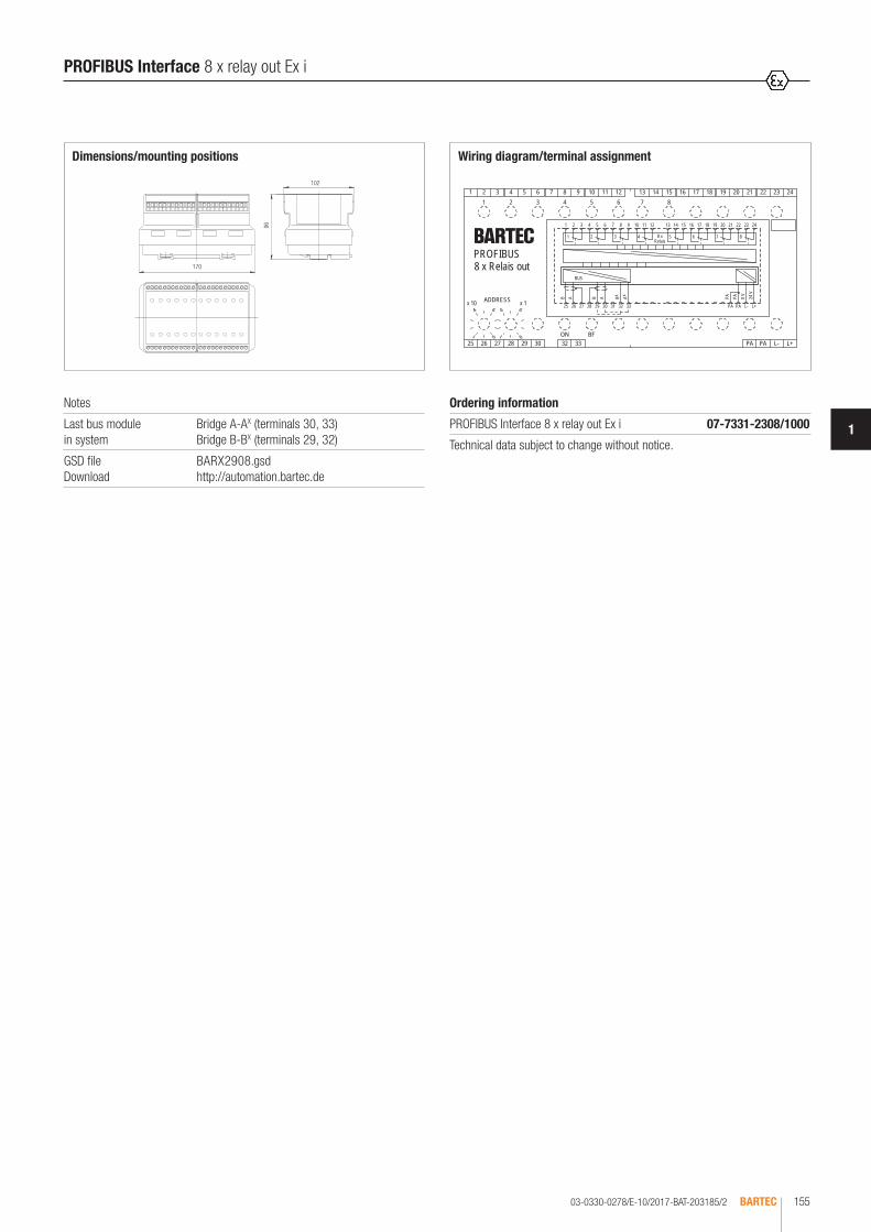
03-0330-0278/E-10/2017-BAT-203185/2 BARTEC 155
1
6421 3 515 16 17 18 19 20 21 22 23 2412
ADDRESSx 10 x 1
1
6
9
4
1
6
9
4
14137 8
ON BF
1110
33
9
32
87
30
6
29
5
28
4
27
3
26
2
25
1
PA L- L+
13 14 15432 5 6 7 8 9 10 11 12
1 2 3 4 5 6 7 8
2423222120191817611
8 xRelais
L+L-PA
PA 0 V 24 V
25 26 27 28 29 30 333231
B A B A
BUS
B Ax x
PA
PA
PA
PROFIBUS8 x Relais out
Wiring diagram/terminal assignment
PROFIBUS Interface 8 x relay out Ex i
Notes
Last bus module in system
Bridge A-AX (terminals 30, 33) Bridge B-BX (terminals 29, 32)
GSD file Download
BARX2908.gsd http://automation.bartec.de
Ordering information
PROFIBUS Interface 8 x relay out Ex i 07-7331-2308/1000
Technical data subject to change without notice.
102
96
Dimensions/mounting positions
170

03-0330-0711/A-10/2017-BAT-346038/1BARTEC156
8 x 4 to 20 mA in Ex i In the Ex i version, the MODEX 8 x 4 to 20 mA module with 8 analogue inputs enables 8 analogue intrinsically safe signals to be fed in or eval-uated. For example, intrinsically safe two-wire transmitters or active 4 - 20 mA signals can be imported as signals. 8 x 4 to 20 mA in & out Ex i In the Ex i ver-sion, the MODEX 4 x 4 to 20 mA module with 4 analogue inputs enables 4 ana-logue intrinsically safe signals to be fed in or evaluated and additionally the control of intrinsically safe actuators using 4 x 4 to 20 mA outputs. The input signal has 15-bit resolution plus sign and is transmitted with high interference resistance. Both modules are connected to the process control system via the PROFIBUS- DP. Coding rotary switches are available for addressing the module. Diagnostics data indicating the status of the outputs with respect to a disconnection or short-circuit can also be transmitted in addition to the user data. This is also displayed on the module itself using LEDs.
Technical data
Construction Flameproof, clip-on enclosure to TH 35
Enclosure material High-quality thermoplastic
Protection class Electronic assembly IP 66 EN/IEC 60529 Terminals IP 20 EN/IEC 60529 Terminals with cover IP 30 EN/IEC 60529
Terminals 2.5 mm², fine stranded
Device designation Front plate for labelling
Displays LEDs on front panel
Storage temperature -40 °C to +60 °C
Ambient temperature -25 °C to +60 °C at T4
Weight 2.1 kg
Explosion protection
Marking ATEX II 2(1)G Ex db e [ia Ga] IIC/IIB Gb I M2 Ex db e [ia Ma] I Mb
Certification PTB 97 ATEX 1066 U TÜV 01 ATEX 1724
Marking IECEx Ex db e [ia Ga] IIC/IIB Gb Ex db e [ia Ma] I Mb
Certification IECEx PTB 11.0082U IECEx TUN 11.0026X
Marking CSA Class I, Zone 1, IIC A/Ex d e [ia] IIC Gb
Certification CSA 2011-2484303U
Other approvals and certificates, see www.bartec.de
Installation Type 17-6583-.H../.... II (1) G / II (1) D
[Ex ia Ga] IIC/IIB [Ex ia Da] IIIC/IIIB For further data see test certificates.
Safety data U0 = 26.7 V I0 = 89.9 mA P0 = 600 mW L0 = 5 mH (IIC)/18 mH (IIB) C0 = 93 nF (IIC)/720 nF (IIB)
External 4 to 20 mA-signals: Ui = 50 V Ii = 87.7 mA
PROFIBUS Interface 8 x 4 to 20 mA in/4 x 4 to 20 mA in/out (15-bit plus sign) Ex i
Electrical data
Supply voltage electronics (L +, L-)
DC 24 V (20 to 30 V)
Power consumption (L +, L-)
7.8 W
Reverse polarity protection (L +, L-)
Yes
Power dissipation max. 4.9 W (Module)
Galvanic isolation Power supply//bus//circuitry//inputs
Bus interface RS485 with screw terminals
Displays Status ON, BF, SFInputs 8 x LEDs LED yellow, sensor active LED red, open circuit/short circuit
Inputs/outputs
Signal range 4 to 20 mA
Transmisiion range Current Range 4 to 20 mA
21.5 mA 7380hex 29568 dec. Valve at short circuit 7FFFhex
20 mA 6000hex 27648 dec.
4 mA 0000hex 0 dec. Valve at open circuit 8000hex
3.5 mA 8000hex -32768 dec.
Resolution 15-bit plus sign
Precision ± 0.1 % (with a shielded cable)
Line monitoring Group error message for each Channel via bus
Input Channel data
Supply for 2-wire transmitter
Ua = 16 V to 20 mA, all Channels are short-circuit proof at the same time
Input resistance External 4 to 20 mA-signals: Ri = 234 Ω + approx. 2 V (3 diodes)
Conversion time < 70 ms
Output Channel data
Output resistance Ri = 367 Ω
Quantising 366.2 nA/LSB
Load < 500 Ω

03-0330-0711-10/2017-BAT-346038/2 BARTEC 157
1
.3
.2
24 V
1514
29
0 VPA
L-PA L+
X4.1
30
SFBFON9
4
1
ADDRESS66 4
9
x 1
1
x 10
25 26 27 28 29 30 32 33
32
531 2 4 6
BUS
ABABAB
32 33
1
Ex i
16
7 81 2 3 4 5 6 7 8 9 10 11 12 13 14 15 16
PA L- L+
x x PA
PA
PA
17 18 19 20 21 22 23 24
17 18 19 20 21 22 23 24
27 282625
1098765 314 1211.20.15 .16 .19.18.17.12 X1.13 .14.10 .11X1.1 .6 .9.8.7.4 .5.2 .22.21
42.32.22.12.4X9.8.6.5.4.3.
.24.23PROFIBUS8 x analog out
.9X4.8.6.5.4.3.2X4.1
.21X1.1 .5 .7.4.3 .6 .8 .9 .10 .12 X1.13 91.11. .18.15 .16 .17.14.2 .20 .22 .23 .24
.24.23.22X4.21
321 16
PAx
PA L- L+
x
17
PA
PA
2019 22
20
23
17 19 232213 14
1
3332B A B A B A
BUS
ON BF SF
4
9
11
3332302928272625
6421 3 5
2 3 4 5 6 7 8 9 10 11 12 13 14
24 V
0 VPA
PA L- L+25 26 27 28 29 306
1
4
9
6
1
x 1x 10 ADDRESS
105 6 7 98487
16
Ex i
12
PROFIBUS4 x analog in4 x analog out
Wiring diagram/terminal assignment 8 x 4 to 20 mA in
Wiring diagram/terminal assignment 4 x 4 to 20 mA in/outNote
Last bus module in system
Bridge A-AX (terminals 30, 33) Bridge B-BX (terminals 29, 32)
GSD file
Download
BARX2302.gsd (8 x 4 to 20 mA in Ex i) BARX2303.gsd (4 x 4 to 20 mA in/out Ex i)
http://automation.bartec.de
Ordering information
PROFIBUS Interface 8 x 4 to 20 mA in Ex i 07-7331-230H/0001
PROFIBUS Interface 4 x 4 to 20 mA in/out Ex i 07-7331-230H/1011
Technical data subject to change without notice.
102
96
Dimensions/mounting positions
170
PROFIBUS Interface 8 x 4 to 20 mA in/4 x 4 to 20 mA in/out (15-bit plus sign) Ex i

03-0330-0285/F-10/2017-BAT-208351/1BARTEC158
8 x 4 to 20 mA in Ex i In the Ex i version, the MODEX 8 x 4 to 20 mA module with 8 analogue inputs enables 8 analogue intrinsically safe signals to be fed in or evaluated. For example, intrinsically safe two-wire transmitters or active 4 - 20 mA signals can be imported as signals. 4 x 4 to 20 mA in & out Ex i In the Ex i version, the MODEX 4 x 4 to 20 mA module with 4 analogue inputs enables 4 analogue intrinsically safe signals to be fed in or evaluated and addi-tionally the control of intrinsically safe actuators using 4 x 4 to 20 mA outputs. The input signal has 16-bit resolution and is transmitted with high interference resistance. Both modules are connected to the process control system via the PROFIBUS-DP. Coding rotary switches are available for addressing the module. Diagnostics data indicating the status of the outputs with respect to a discon-nection or short-circuit can also be transmitted in addition to the user data. This is also displayed on the module itself using LEDs.
Technical data
Construction Flameproof, clip-on enclosure to TH 35
Enclosure material High-quality thermoplastic
Protection class Electronic assembly IP 66 EN/IEC 60529 Terminals IP 20 EN/IEC 60529 Terminals with cover IP 30 EN/IEC 60529
Terminals 2.5 mm², fine stranded
Device designation Front plate for labelling
Displays LEDs on front panel
Storage temperature -40 °C to +60 °C
Ambient temperature -25 °C to +60 °C at T4
Weight 2.1 kg
Explosion protection
Marking ATEX II 2(1)G Ex db e [ia Ga] IIC/IIB Gb I M2 Ex db e [ia Ma] I Mb
Certification PTB 97 ATEX 1066 U TÜV 01 ATEX 1724
Marking IECEx Ex db e [ia Ga] IIC/IIB Gb Ex db e [ia Ma] I Mb
Certification IECEx PTB 11.0082U IECEx TUN 11.0026X
Marking CSA Class I Zone 1 IIC A/Ex d e [ia] IIC Gb
Certification CSA 2011-2484303U
Other approvals and certificates, see www.bartec.de
Installation Type 17-6583-.H../.... II (1) G / II (1) D
[Ex ia Ga] IIC/IIB [Ex ia Da] IIIC/IIIB For further data see test certificates.
Safety data U0 = 26.7 V I0 = 89.9 mA P0 = 600 mW L0 = 5 mH (IIC)/18 mH (IIB) C0 = 93 nF (IIC)/720 nF (IIB)
External 4 to 20 mA-signals Ui = 50 V Ii = 87.7 mA
PROFIBUS Interface 8 x 4 to 20 mA in/4 x 4 to 20 mA in/out (16 Bit)
Electrical data
Supply voltage electronics (L +, L-)
DC 24 V (20 to 30 V)
Power consumption (L +, L-)
7.8 W
Reverse polarity protection (L +, L-)
Yes
Power dissipation max. 4.9 W (Module)
Galvanic isolation Power supply//bus//circuitry//inputs
Bus interface RS485 with screw terminals
Displays Status ON, BF, SFInputs 8 x LEDs LED yellow, sensor active LED red, open circuit/short circuit
Inputs/outputs
Signal range 4 to 20 mA
Transmission range Current Range 4 to 20 mA
24 mA FFFFhex 65535 dec. Valve at short circuit 7FFFhex
20 mA D554hex 54612 dec.
4 mA 2AAAhex 10922 dec. Valve at open circuit 8000hex
0 mA 0000hex 0
Resolution 16 bit
Precision ± 0.1 % (with a shielded cable)
Line monitoring Group error message for each Channel via bus
Input Channel data
Supply for 2-wire transmitter
Ua = 16 V to 20 mA, all Channels are short-circuit proof at the same time
Input resistance External 4 to 20 mA-signals: Ri = 234 Ω + approx. 2 V (3 diodes)
Conversion time < 70 ms
Output Channels
Output resistance Ri = 367 Ω
Quantising 366.2 nA/LSB
Load < 500 Ω
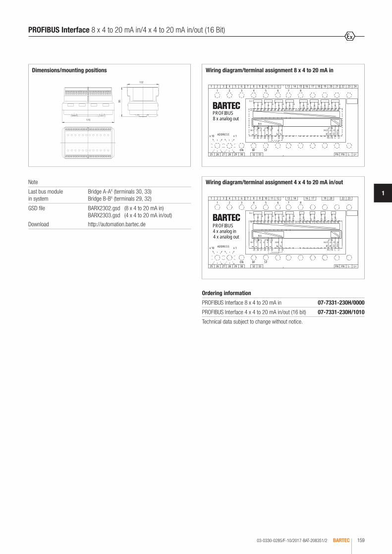
03-0330-0285/F-10/2017-BAT-208351/2 BARTEC 159
1
.3
.2
24 V
1514
29
0 VPA
L-PA L+
X4.1
30
SFBFON9
4
1
ADDRESS66 4
9
x 1
1
x 10
25 26 27 28 29 30 32 33
32
531 2 4 6
BUS
ABABAB
32 33
1
Ex i
16
7 81 2 3 4 5 6 7 8 9 10 11 12 13 14 15 16
PA L- L+
x x PA
PA
PA
17 18 19 20 21 22 23 24
17 18 19 20 21 22 23 24
27 282625
1098765 314 1211.20.15 .16 .19.18.17.12 X1.13 .14.10 .11X1.1 .6 .9.8.7.4 .5.2 .22.21
42.32.22.12.4X9.8.6.5.4.3.
.24.23PROFIBUS8 x analog out
.9X4.8.6.5.4.3.2X4.1
.21X1.1 .5 .7.4.3 .6 .8 .9 .10 .12 X1.13 91.11. .18.15 .16 .17.14.2 .20 .22 .23 .24
.24.23.22X4.21
321 16
PAx
PA L- L+
x
17
PA
PA
2019 22
20
23
17 19 232213 14
1
3332B A B A B A
BUS
ON BF SF
4
9
11
3332302928272625
6421 3 5
2 3 4 5 6 7 8 9 10 11 12 13 14
24 V
0 VPA
PA L- L+25 26 27 28 29 306
1
4
9
6
1
x 1x 10 ADDRESS
105 6 7 98487
16
Ex i
12
PROFIBUS4 x analog in4 x analog out
Wiring diagram/terminal assignment 8 x 4 to 20 mA in
Wiring diagram/terminal assignment 4 x 4 to 20 mA in/outNote
Last bus module in system
Bridge A-AX (terminals 30, 33) Bridge B-BX (terminals 29, 32)
GSD file
Download
BARX2302.gsd (8 x 4 to 20 mA in) BARX2303.gsd (4 x 4 to 20 mA in/out)
http://automation.bartec.de
Ordering information
PROFIBUS Interface 8 x 4 to 20 mA in 07-7331-230H/0000
PROFIBUS Interface 4 x 4 to 20 mA in/out (16 bit) 07-7331-230H/1010
Technical data subject to change without notice.
102
96
Dimensions/mounting positions
170
PROFIBUS Interface 8 x 4 to 20 mA in/4 x 4 to 20 mA in/out (16 Bit)

03-0330-0415/E-10/2017-BAT-239830/1BARTEC160
Electrical data
Supply voltage DC 20 V to 30 V
Nominal power consumption
max. 70 mA
Operational readiness indicator
LED green
RS485 interface PROFIBUS-DP, PROFIBUS-IS, EN 61158-2; EN 61784-1
Connection resistance
Ex e PROFIBUS-DP Standard Ex i PROFIBUS-IS StandardInput manual connectable Output Set
Data direction switching automatic
Bus activity dynamic
Transmission rate Ex e Kbit/s- 4, 8/9, 6/19, 2/45, 45/93, 75/187, 5/250/375/500/750 Mbit/s- 1.0/1.5/2.0/3.0/6.0/12.0
Transmission rate Ex i Kbit/s- 4, 8/9, 6/19, 2/45, 45/93, 75/187, 5/250/375/500/750 Mbit/s- 1.0/1.5
Transmission rate switchover
manual
Dimensions/mounting positions
Module width: 30 mm/75 mm
Technical data
Construction Flameproof, clip-on enclosure for TH 35
Enclosure material High-quality thermoplastics
Protection class Electronic assembly IP 66 EN/IEC 60529 Terminals IP 20 EN/IEC 60529 Terminals with cover IP 30 EN/IEC 60529
Terminals 2.5 mm2, fine stranded
Device designation written marking labels
Displays LED green Operational readiness LED green/yellow Bus activity
Storage temperature -25 °C to +70 °C
Ambient temperature -25 °C to +60 °C at T4
Weight Module width 30 mm: 180 g Module width 75 mm: 250 g
Dimensions (H x W x D) 94 mm x 30 mm x 91 mm 94 mm x 75 mm x 91 mm
PROFIBUS-DP Coupler/PROFIBUS-DP Repeater/PROFIBUS Gateway DP/IS
The PROFIBUS devices have been particularly dimensioned for the industrial requirements of hazardous areas of zone 1. They are used for the separation or generation of new segments, converting the RS485 typical line structure into an open and flexible tree structure. Downstream stations can be coupled to and de-coupled from the superior bus system in a non-reactive and break/short-cir-cuit tolerant manner, even during running bus operation.The devices facilitate a duplication of the signal to realize a redundant connection to a master. The devices are available as PROFIBUS-DP and as PROFIBUS-IS (intrinsically safe).
Explosion protection Ex e
Marking ATEX II 2(1)G Ex db e IIC Gb I M2 Ex db e I Mb
Certification PTB 97 ATEX 1068 U
Marking IECEx Ex db e IIC Gb Ex db e I Mb
Certification IECEx PTB 11.0083U
Marking CSA Class I Zone 1 IIC A/Ex d e IIC Gb
Certification CSA 2011-2484303U
Explosion protection Ex i
Marking ATEX II 2(1)G Ex db e [ib] IIC Gb I M2 Ex db e [ib] I Mb
Certification PTB 97 ATEX 1068 U
Marking IECEx Ex db e [ib] IIC Gb Ex db e [ib] I Mb
Certification IECEx PTB 11.0083U
Marking CSA Class I Zone 1 IIC A/Ex d e [ib] IIC Gb
Certification CSA 2011-2484303U
Installation Type 17-6583-.3.. II (2) G [Ex ib Gb] IIC II (2) D [Ex ib Db] IIIC
IBExU05ATEX1074 IECEx IBE 12.0021
Other approvals and certificates, see www.bartec.de

03-0330-0415/E-10/2017-BAT-239830/2 BARTEC 161
1
e. g. function plan for 4-channel, intrinsically safe circuits
PROFIBUS-DP Coupler - increased safety
Description Options Module width Order no.
PROFIBUS-DP Coupler Ex e, 1 output 30 mm 07-7311-93WP/K1NO
PROFIBUS-DP Coupler Ex e, 2 outputs 30 mm 07-7311-93WP/K2NO
PROFIBUS-DP Coupler Ex e, 4 outputs 75 mm 07-7311-97WP/K4NO
PROFIBUS Gateway DP/IS
Description Options Module width Order no.
PROFIBUS Gateway DP/IS Ex i, 1 output 75 mm 07-7311-97WP/K1EO
PROFIBUS Gateway DP/IS Ex i, 2 outputs 75 mm 07-7311-97WP/K2EO
PROFIBUS Gateway DP/IS Ex i, 4 outputs 75 mm 07-7311-97WP/K4EO
Technical data subject to change without notice.
PROFIBUS-DP Repeater - increased safety
Description Options Module width Order no.
PROFIBUS-DP Repeater Ex e, 1 output 30 mm 07-7311-93WP/R1NO
PROFIBUS-DP Repeater Ex e, 2 outputs 30 mm 07-7311-93WP/R2NO
PROFIBUS-DP Repeater Ex e, 4 outputs 75 mm 07-7311-97WP/R4NO
PROFIBUS-DP Coupler/PROFIBUS-DP Repeater/PROFIBUS Gateway DP/IS

03-0330-0394/C-10/2017-BAT-234374/1BARTEC162
The RS485/PROFIBUS Optical Fibre T-coupler reroutes the PROFIBUS from copper conductors to optical fibres. The coupler is a passive bus participant. The optical fibre T-coupler allows great ranges to be bridged in plants using PROFIBUS, and is resistant to interference. The electronics for the signal con-version are accomodated in the flameproof MODEX enclosure. The transmitter and receiver for the optical fibre T-coupler are activated in an intrinsically safe way, thereby ensuring that the transmission power of the transmitter does not exceed the permitted limits.
RS485/PROFIBUS Optical Fibre T-coupler
Electrical data
Supply voltage DC 20 V to DC 30 V
Power dissipation max. PV = 0.90 W (Module)
Galvanic isolation Bus//power supply//optical fibre
Bus input/output 2-wire remote bus with screw terminals
Optical fibre input/output FSMA Optical fibre plug-in connectors or ST Optical fibre plug-in connectors
Wavelength 850 nm/glass
Displays operation LED green active bus LED yellow
Range 1400 m; 50.0 µm fibre/glass 2600 m; 62.5 µm fibre/glass
Explosion protection
Marking ATEX II 2G Ex db e [ib] IIC Gb I M2 Ex db e [ib] I Mb
Certification PTB 97 ATEX 1068 U TÜV 99 ATEX 1404 X
Marking IECEx Ex db e [ib] IIC Gb Ex db e [ib] I Mb
Certification IECEx PTB 11.0083U IECEx TUN 12.0024X
Marking CSA Class I Zone 1 IIC A/Ex d e [ib] IIC Gb
Certification CSA 2011-2484303U
Other approvals and certificates, see www.bartec.de
Installation Type 17-1923-1133/0000 II (2)G / II (2)D
[Ex ib Gb] IIC [Ex ib Db] IIIC
Optical fibre Transmitter Type 17-2114-0002
II 2G / II 2D Ex ib op is IIC T4 Gb Ex ib IIIC TX* °C Db
Receiver Type 17-2114-0003
II 2G / II 2D Ex ib IIC T4 Gb Ex ib IIIC TX* °C Db
Further safety data see EC type examination certificate.
* See instruction manual for details.
Technical data
Construction Clip-on enclosure to TH 35
Enclosure material High-quality thermoplastic
Protection class At least IP 20
Terminals 2.5 mm2, fine stranded
Device designation Front plate for labelling
Displays LEDs on front panel
Storage temperature -40 °C to +70 °C
Ambient temperature -25 °C to +60 °C at T4
Weight 600 g

03-0330-0394/C-10/2017-BAT-234374/2 BARTEC 163
1
RS485 - Optical fibre coupler
el. BUSel. BUS
RS485 - Optical fibre coupler
Optical fibre up to 2.600 m
Connection example of optical fibre T-coupler
BUS
RS485/PROFIBUS Optical fibre coupler RS485/PROFIBUS Fibre optic link
Wiring diagram/terminal assignment
RS485/PROFIBUS Optical Fibre T-coupler
Ordering information
T-coupler FSMA 07-7311-97WP/4000
T-coupler ST 07-7311-97WP/4010
Technical data subject to change without notice.
Dimensions/mounting positions
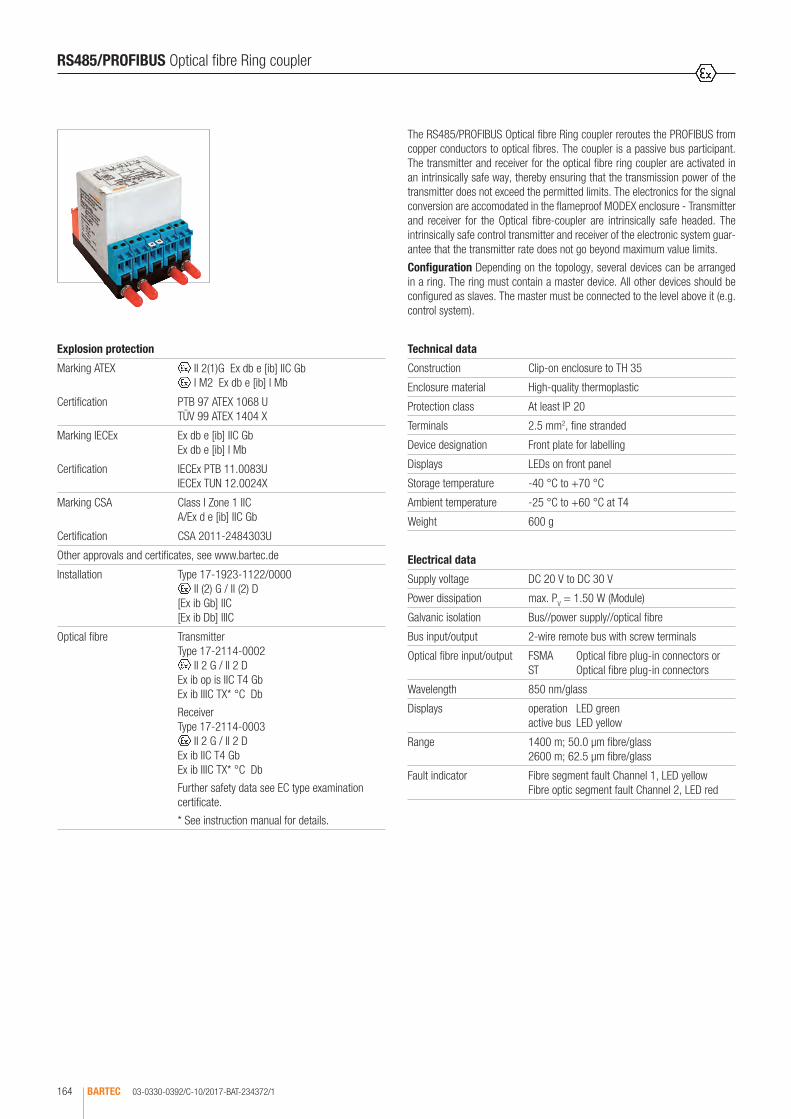
03-0330-0392/C-10/2017-BAT-234372/1BARTEC164
The RS485/PROFIBUS Optical fibre Ring coupler reroutes the PROFIBUS from copper conductors to optical fibres. The coupler is a passive bus participant. The transmitter and receiver for the optical fibre ring coupler are activated in an intrinsically safe way, thereby ensuring that the transmission power of the transmitter does not exceed the permitted limits. The electronics for the signal conversion are accomodated in the flameproof MODEX enclosure - Transmitter and receiver for the Optical fibre-coupler are intrinsically safe headed. The intrinsically safe control transmitter and receiver of the electronic system guar-antee that the transmitter rate does not go beyond maximum value limits.
Configuration Depending on the topology, several devices can be arranged in a ring. The ring must contain a master device. All other devices should be configured as slaves. The master must be connected to the level above it (e.g. control system).
RS485/PROFIBUS Optical fibre Ring coupler
Electrical data
Supply voltage DC 20 V to DC 30 V
Power dissipation max. PV = 1.50 W (Module)
Galvanic isolation Bus//power supply//optical fibre
Bus input/output 2-wire remote bus with screw terminals
Optical fibre input/output FSMA Optical fibre plug-in connectors or ST Optical fibre plug-in connectors
Wavelength 850 nm/glass
Displays operation LED green active bus LED yellow
Range 1400 m; 50.0 µm fibre/glass 2600 m; 62.5 µm fibre/glass
Fault indicator Fibre segment fault Channel 1, LED yellow Fibre optic segment fault Channel 2, LED red
Explosion protection
Marking ATEX II 2(1)G Ex db e [ib] IIC Gb I M2 Ex db e [ib] I Mb
Certification PTB 97 ATEX 1068 U TÜV 99 ATEX 1404 X
Marking IECEx Ex db e [ib] IIC Gb Ex db e [ib] I Mb
Certification IECEx PTB 11.0083U IECEx TUN 12.0024X
Marking CSA Class I Zone 1 IIC A/Ex d e [ib] IIC Gb
Certification CSA 2011-2484303U
Other approvals and certificates, see www.bartec.de
Installation Type 17-1923-1122/0000 II (2) G / II (2) D
[Ex ib Gb] IIC [Ex ib Db] IIIC
Optical fibre Transmitter Type 17-2114-0002
II 2 G / II 2 D Ex ib op is IIC T4 Gb Ex ib IIIC TX* °C Db
Receiver Type 17-2114-0003
II 2 G / II 2 D Ex ib IIC T4 Gb Ex ib IIIC TX* °C Db
Further safety data see EC type examination certificate.
* See instruction manual for details.
Technical data
Construction Clip-on enclosure to TH 35
Enclosure material High-quality thermoplastic
Protection class At least IP 20
Terminals 2.5 mm2, fine stranded
Device designation Front plate for labelling
Displays LEDs on front panel
Storage temperature -40 °C to +70 °C
Ambient temperature -25 °C to +60 °C at T4
Weight 600 g
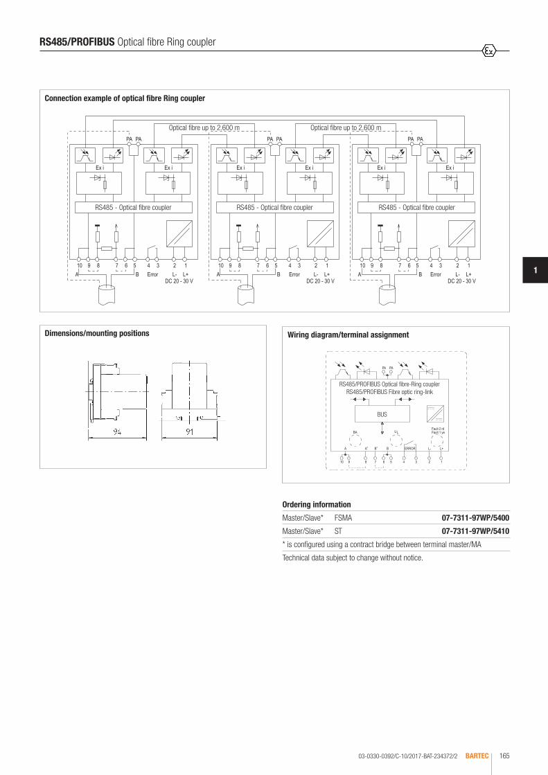
03-0330-0392/C-10/2017-BAT-234372/2 BARTEC 165
1
Connection example of optical fibre Ring coupler
Optical fibre up to 2.600 m Optical fibre up to 2.600 m
RS485 - Optical fibre coupler RS485 - Optical fibre coupler RS485 - Optical fibre coupler
BUS
RS485/PROFIBUS Optical fibre-Ring coupler RS485/PROFIBUS Fibre optic ring-link
Wiring diagram/terminal assignment
RS485/PROFIBUS Optical fibre Ring coupler
Ordering information
Master/Slave* FSMA 07-7311-97WP/5400
Master/Slave* ST 07-7311-97WP/5410
* is configured using a contract bridge between terminal master/MA
Technical data subject to change without notice.
Dimensions/mounting positions

03-0330-0393/C-10/2017-BAT-234373/1BARTEC166
The RS485/PROFIBUS optical fibre branch coupler reroutes the PROFIBUS from copper conductors to optical fibres. The coupler is a passive bus par-ticipant. The transmitter and receiver for the optical fibre branch coupler are activated in an intrinsically safe way, thereby ensuring that the transmission power of the transmitter does not exceed the permitted limits. The electronics for the signal conversion are accomodated in the flameproof MODEX enclo-sure. Transmitter and receiver for the Optical fibre coupler are intrinsically safe headed during the execution. The transmitter and receiver for the optical fibre coupler are activated in an intrinsically safe way, thereby ensuring that the transmission power of the transmitter does not exceed the permitted limits.
RS485/PROFIBUS Optical fibre branch coupler
Electrical data
Supply voltage DC 20 V to DC 30 V
Power dissipation max. PV = 0.85 W (Module)
Galvanic isolation Bus//power supply//optical fibre
Bus input/output 2-wire remote bus with screw terminals
Optical fibre input/output F-SMA Optical fibre plug-in connectors or ST Optical fibre plug-in connectors
Wavelength 850 nm/glass
Displays operation LED green active bus LED yellow
Range 1400 m; 50.0 µm fibre/glass 2600 m; 62.5 µm fibre/glass
Explosion protection
Marking ATEX II 2(1)G Ex d e [ib] IIC Gb I M2 Ex d e [ib] I Mb
Certification PTB 97 ATEX 1068 U TÜV 99 ATEX 1404 X
Marking IECEx Ex d e [ib] IIC Gb Ex d e [ib] I Mb
Certification IECEx PTB 11.0083U IECEx TUN 12.0024X
Marking CSA Class I Zone 1 IIC A/Ex d e [ib] IIC Gb
Certification CSA 2011-2484303U
Other approvals and certificates, see www.bartec.de
Installation Type 17-1923-1133/0000 II (2) G / II (2) D
[Ex ib Gb] IIC [Ex ib Db] IIIC
Optical fibre Transmitter Type 17-2114-0002
II 2 G / II 2 D Ex ib op is IIC T4 Gb Ex ib IIIC TX* °C Db
Receiver Type 17-2114-0003
II 2 G / II 2 D Ex ib IIC T4 Gb Ex ib IIIC TX* °C Db
Further safety data see EC type examination certificate.
* See instruction manual for details.
Technical data
Construction Clip-on enclosure to TH 35
Enclosure material High-quality thermoplastic
Protection class At least IP 20
Terminals 2.5 mm2, fine stranded
Device designation Front plate for labelling
Displays LEDs on front panel
Storage temperature -40 °C to +70 °C
Ambient temperature -25 °C to +60 °C at T4
Weight 600 g

03-0330-0393/C-10/2017-BAT-234373/2 BARTEC 167
1
Connection example of optical fibre branch coupler
Optical fibre up to 2.600 m
RS485 - Optical fibre coupler RS485 - Optical fibre coupler
BUS
RS485/PROFIBUS Optical fibre-coupler RS485/PROFIBUS Fibre optic link
Wiring diagram/terminal assignment
RS485/PROFIBUS Optical fibre branch coupler
Ordering information
Optical fibre branch coupler FSMA 07-7311-97WP/6000
Optical fibre branch coupler ST 07-7311-97WP/6010
Technical data subject to change without notice.
Dimensions/mounting positions

03-0330-0282/F-10/2017-BAT-206448BARTEC168
The PROFIBUS Interface terminator is an active bus terminator. Its essential benefit is the fact that bus devices can be switched off, removed or replaced without impairing data transfer. This especially applies to bus devices on both ends of the bus line through which terminal resistances previously had to be switched and supplied.
PROFIBUS Interface terminator
Technical data
Construction Flameproof, clip-on enclosure for TH 35 rail
Enclosure material High-quality thermoplastics
Protection class Module IP 66 EN/IEC 60529 Terminals IP 20 EN/IEC 60529
Terminals 2.5 mm2, fine stranded
Mounting rail TH 35 x 7.5 (15) EN 60715
Device designation Front plate for labelling
Storage temperature -40 °C to +70 °C
Ambient temperature -25 °C to +60 °C at T4
Weight 0.250 kg
Electrical data
Supply voltage DC 20 V to 30 V
Power consumption Ptot. = 0.3 W
Explosion protection
Marking ATEX II 2G Ex d e IIC Gb I M2 Ex d e I Mb
Certification PTB 97 ATEX 1068 U
Marking IECEx Ex d e IIC Gb Ex d e I Mb
Certification IECEx PTB 11.0083U
Marking CSA Class I, Zone 1, IIC A/Ex d e [ia] IIC Gb
Certification CSA 2011-2484303U
Other approvals and certificates, see www.bartec.de
Wiring diagram/terminal assigment
Ordering information
PROFIBUS Interface terminator 07-7311-93WP/0000
Technical data subject to change without notice.
Module width: 30 mm
Dimensions/mounting position
L+
B A PA PA
ON
L-L+ L-
Shld
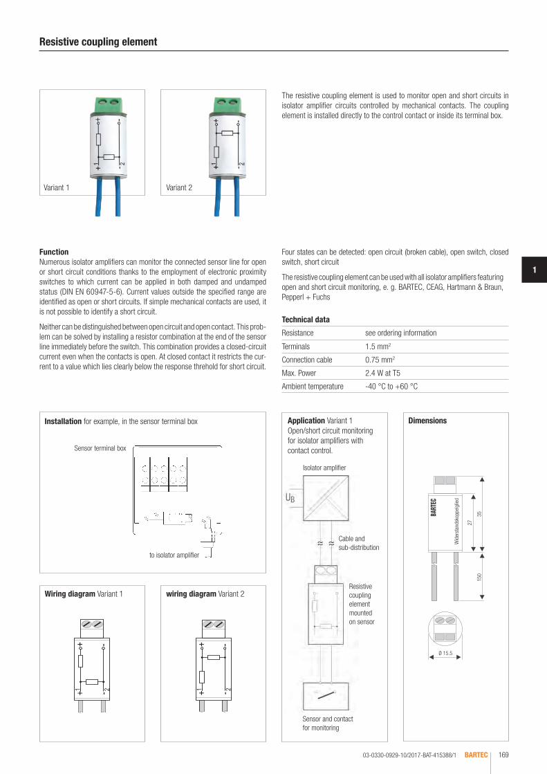
03-0330-0929-10/2017-BAT-415388/1 BARTEC 169
1
Resistive coupling element
FunctionNumerous isolator amplifiers can monitor the connected sensor line for open or short circuit conditions thanks to the employment of electronic proximity switches to which current can be applied in both damped and undamped status (DIN EN 60947-5-6). Current values outside the specified range are identified as open or short circuits. If simple mechanical contacts are used, it is not possible to identify a short circuit.
Neither can be distinguished between open circuit and open contact. This prob-lem can be solved by installing a resistor combination at the end of the sensor line immediately before the switch. This combination provides a closed-circuit current even when the contacts is open. At closed contact it restricts the cur-rent to a value which lies clearly below the response threhold for short circuit.
Technical data
Resistance see ordering information
Terminals 1.5 mm2
Connection cable 0.75 mm2
Max. Power 2.4 W at T5
Ambient temperature -40 °C to +60 °C
to isolator amplifier
Installation for example, in the sensor terminal box Application Variant 1Open/short circuit monitoring for isolator amplifiers with contact control.
Resistive coupling element mounted on sensor
Isolator amplifier
Cable and sub-distribution
Sensor and contact for monitoring
Wiring diagram Variant 1 wiring diagram Variant 2
Sensor terminal box
Dimensions
Wid
erst
ands
kopp
elgl
ied
27
150
Ø 15.5
35
Four states can be detected: open circuit (broken cable), open switch, closed switch, short circuit
The resistive coupling element can be used with all isolator amplifiers featuring open and short circuit monitoring, e. g. BARTEC, CEAG, Hartmann & Braun, Pepperl + Fuchs
The resistive coupling element is used to monitor open and short circuits in isolator amplifier circuits controlled by mechanical contacts. The coupling element is installed directly to the control contact or inside its terminal box.
Variant 1 Variant 2
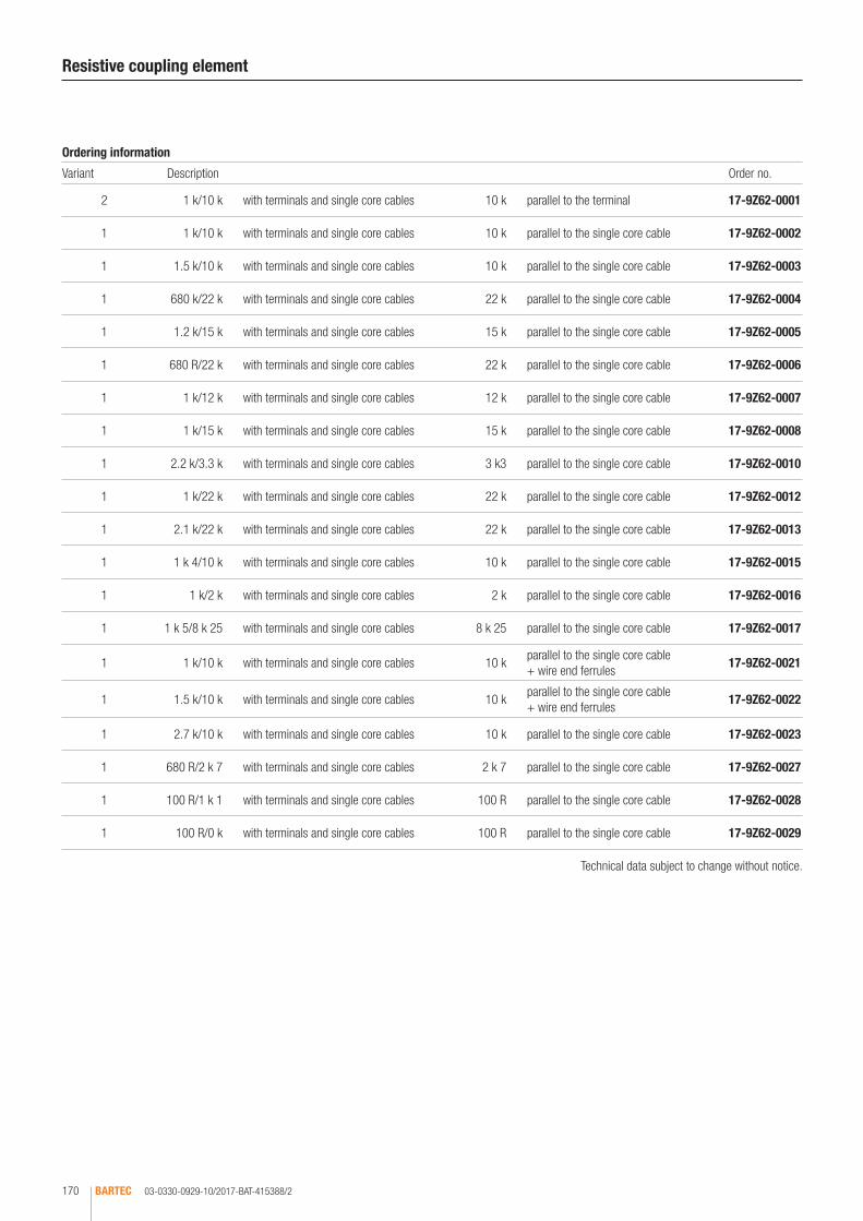
03-0330-0929-10/2017-BAT-415388/2BARTEC170
Resistive coupling element
Ordering information
Variant Description Order no.
2 1 k/10 k with terminals and single core cables 10 k parallel to the terminal 17-9Z62-0001
1 1 k/10 k with terminals and single core cables 10 k parallel to the single core cable 17-9Z62-0002
1 1.5 k/10 k with terminals and single core cables 10 k parallel to the single core cable 17-9Z62-0003
1 680 k/22 k with terminals and single core cables 22 k parallel to the single core cable 17-9Z62-0004
1 1.2 k/15 k with terminals and single core cables 15 k parallel to the single core cable 17-9Z62-0005
1 680 R/22 k with terminals and single core cables 22 k parallel to the single core cable 17-9Z62-0006
1 1 k/12 k with terminals and single core cables 12 k parallel to the single core cable 17-9Z62-0007
1 1 k/15 k with terminals and single core cables 15 k parallel to the single core cable 17-9Z62-0008
1 2.2 k/3.3 k with terminals and single core cables 3 k3 parallel to the single core cable 17-9Z62-0010
1 1 k/22 k with terminals and single core cables 22 k parallel to the single core cable 17-9Z62-0012
1 2.1 k/22 k with terminals and single core cables 22 k parallel to the single core cable 17-9Z62-0013
1 1 k 4/10 k with terminals and single core cables 10 k parallel to the single core cable 17-9Z62-0015
1 1 k/2 k with terminals and single core cables 2 k parallel to the single core cable 17-9Z62-0016
1 1 k 5/8 k 25 with terminals and single core cables 8 k 25 parallel to the single core cable 17-9Z62-0017
1 1 k/10 k with terminals and single core cables 10 kparallel to the single core cable + wire end ferrules
17-9Z62-0021
1 1.5 k/10 k with terminals and single core cables 10 kparallel to the single core cable + wire end ferrules
17-9Z62-0022
1 2.7 k/10 k with terminals and single core cables 10 k parallel to the single core cable 17-9Z62-0023
1 680 R/2 k 7 with terminals and single core cables 2 k 7 parallel to the single core cable 17-9Z62-0027
1 100 R/1 k 1 with terminals and single core cables 100 R parallel to the single core cable 17-9Z62-0028
1 100 R/0 k with terminals and single core cables 100 R parallel to the single core cable 17-9Z62-0029
Technical data subject to change without notice.
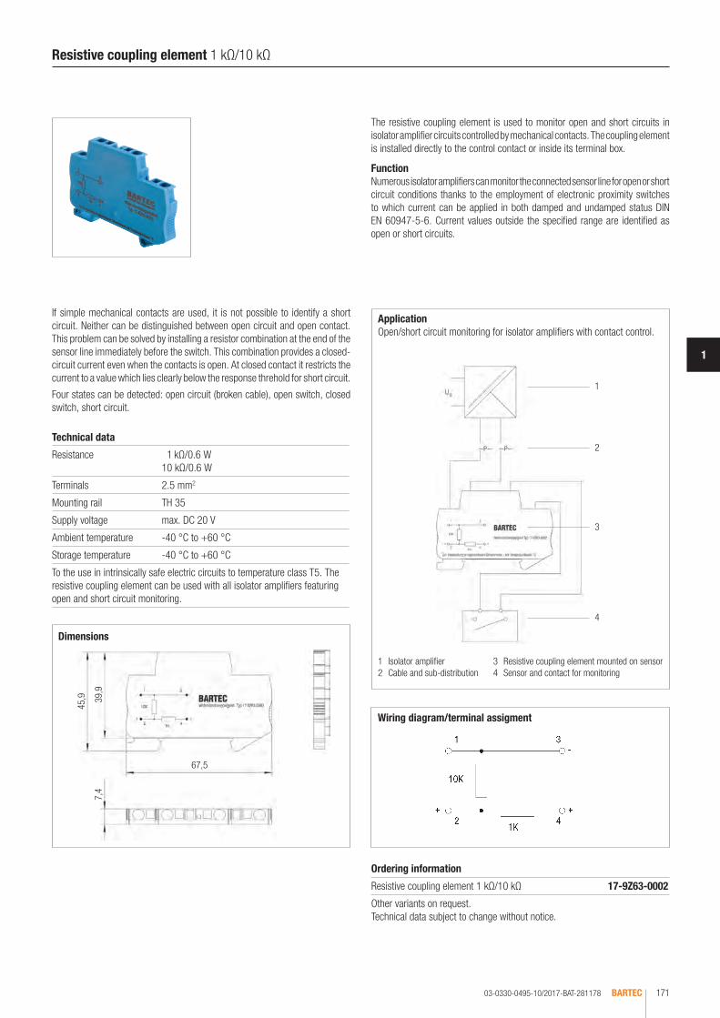
03-0330-0495-10/2017-BAT-281178 BARTEC 171
1
Dimensions
1 Isolator amplifier2 Cable and sub-distribution
3 Resistive coupling element mounted on sensor4 Sensor and contact for monitoring
Wiring diagram/terminal assigment
Application Open/short circuit monitoring for isolator amplifiers with contact control.
1
4
2
3
45,9 39
,9
67,5
7,4
Resistive coupling element 1 kΩ/10 kΩ
Ordering information
Resistive coupling element 1 kΩ/10 kΩ 17-9Z63-0002
Other variants on request. Technical data subject to change without notice.
The resistive coupling element is used to monitor open and short circuits in isolator amplifier circuits controlled by mechanical contacts. The coupling element is installed directly to the control contact or inside its terminal box.
FunctionNumerous isolator amplifiers can monitor the connected sensor line for open or short circuit conditions thanks to the employment of electronic proximity switches to which current can be applied in both damped and undamped status DIN EN 60947-5-6. Current values outside the specified range are identified as open or short circuits.
Technical data
Resistance 1 kΩ/0.6 W 10 kΩ/0.6 W
Terminals 2.5 mm2
Mounting rail TH 35
Supply voltage max. DC 20 V
Ambient temperature -40 °C to +60 °C
Storage temperature -40 °C to +60 °C
To the use in intrinsically safe electric circuits to temperature class T5. The resistive coupling element can be used with all isolator amplifiers featuring open and short circuit monitoring.
If simple mechanical contacts are used, it is not possible to identify a short circuit. Neither can be distinguished between open circuit and open contact. This problem can be solved by installing a resistor combination at the end of the sensor line immediately before the switch. This combination provides a closed-circuit current even when the contacts is open. At closed contact it restricts the current to a value which lies clearly below the response threhold for short circuit.
Four states can be detected: open circuit (broken cable), open switch, closed switch, short circuit.
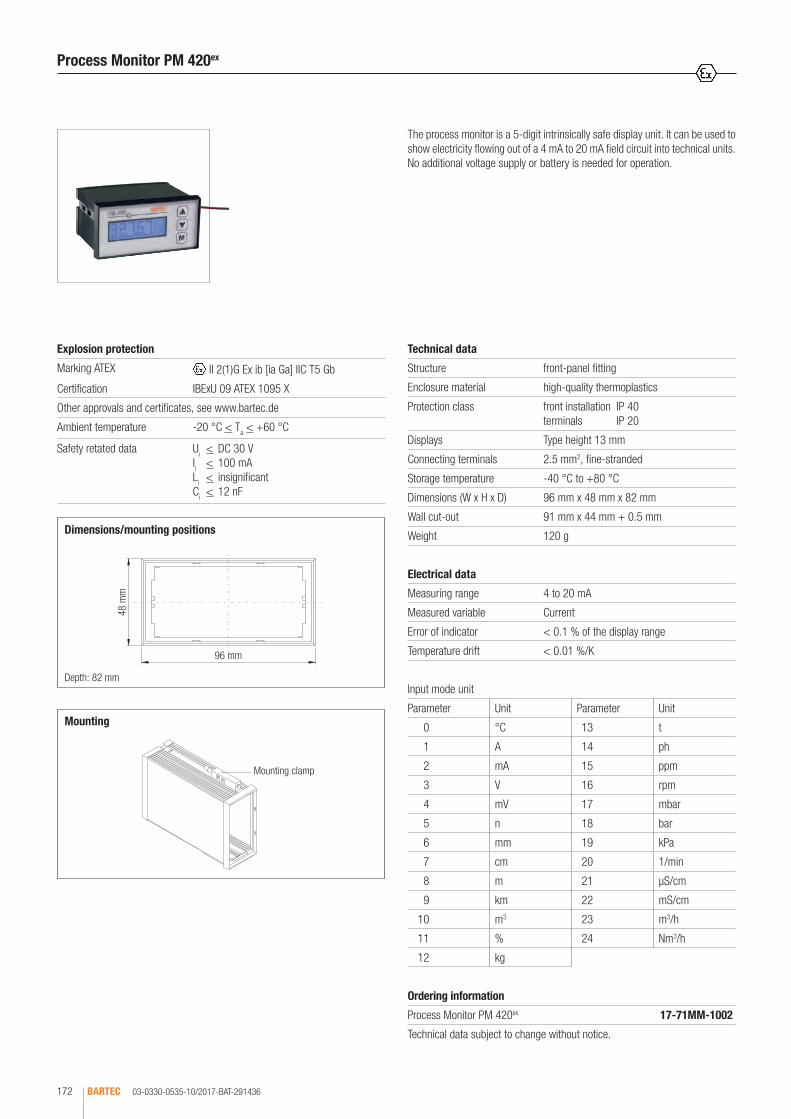
03-0330-0535-10/2017-BAT-291436BARTEC172
Dimensions/mounting positions
Mounting clamp
Depth: 82 mm
96 mm
48 m
m
Input mode unit
Parameter Unit Parameter Unit
0 °C 13 t
1 A 14 ph
2 mA 15 ppm
3 V 16 rpm
4 mV 17 mbar
5 n 18 bar
6 mm 19 kPa
7 cm 20 1/min
8 m 21 µS/cm
9 km 22 mS/cm
10 m3 23 m3/h
11 % 24 Nm3/h
12 kg
Mounting
The process monitor is a 5-digit intrinsically safe display unit. It can be used to show electricity flowing out of a 4 mA to 20 mA field circuit into technical units. No additional voltage supply or battery is needed for operation.
Process Monitor PM 420ex
Technical data
Structure front-panel fitting
Enclosure material high-quality thermoplastics
Protection class front installation IP 40 terminals IP 20
Displays Type height 13 mm
Connecting terminals 2.5 mm2, fine-stranded
Storage temperature -40 °C to +80 °C
Dimensions (W x H x D) 96 mm x 48 mm x 82 mm
Wall cut-out 91 mm x 44 mm + 0.5 mm
Weight 120 g
Electrical data
Measuring range 4 to 20 mA
Measured variable Current
Error of indicator < 0.1 % of the display range
Temperature drift < 0.01 %/K
Explosion protection
Marking ATEX II 2(1)G Ex ib [ia Ga] IIC T5 Gb
Certification IBExU 09 ATEX 1095 X
Other approvals and certificates, see www.bartec.de
Ambient temperature -20 °C < Ta < +60 °C
Safety retated data Ui < DC 30 V Ii < 100 mA Li < insignificant Ci < 12 nF
Ordering information
Process Monitor PM 420ex 17-71MM-1002
Technical data subject to change without notice.

MODEX SWITCHING AND CONTROL COMPONENTS

CONTENT
IP 30 isolator terminal, 2-pole 07-7311-6131/EE00
176
Fuse up to 1.25 A with double terminals 07-7311-61J2/..20
177
Fuse up to 1.25 A with single terminals 07-7311-61J2/.TA0
178
Fuse up to 2.5 A 07-7311-63J2/..00
179
Fuse up to 6.3 A 07-7311-93J2/..00
180
Fuse up to 6.3 A, quick-acting 07-7311-93J2/..00
181
Freewheeling diode, single 07-7311-61GF/54.0
182
Freewheeling diode, double 07-7311-63GF/5300
183
Measuring resistor max. 0.8 Watt 07-7311-61TW/..00
184
Lamp test circuit 07-7311-97GW/E3K0
185
Resistors max. 1.2 Watt 07-7311-63TW/....
186 - 187
Miniature switching relay 07-7311-6371/.000
188
Relay, 1 changeover contact/2 changeover contacts 07-7311-937./.000
189 - 190
Power relay 07-7311-9772/.310
191
Isolator relay, galv. insulation acc. to EN/IEC 60079-0 and EN/IEC 60079-11 07-7311-937./..00
192 - 193
Cradle relay AC 07-7331-977./.100
194 - 195
Cradle relay DC 07-7331-977./.100
196 - 197
Transformer AC 24 V/500 mA 07-7311-97S3/H3N0
198
AC/DC converter DC 24 V/450 mA 07-7311-97S7/AAMO
199
Power supply unit DC 24 V/2 A 07-7331-1201/0000
200
Power supply unit AC/DC 110 to 250 V 07-7311-97S9/J..0
201
Power Supply 100 W for Zone 1 + 2 and Zone 21 + 2207-7381-1.00
202
Optocoupler, 2-channel 07-7311-93QH/C5M0
203
Isolator amplifier, 4-channel with display 07-7311-97MT/BA..
204 - 205
Measuring transducer for Pt100, galvanically isolated 07-7311-93T5/.350
206
Power contactor 07-7311-97ER/31.0
207

03-0330-0153/G-01/2017-BAT-128925BARTEC176
The MODEX series offers an isolator terminal which can be used for service and test tasks and for conventional manual switching functions. Thanks to the visibly clear distinction between switching positions and extremely small en-closure with 4 integrated terminals, the isolator terminal is very easy to install. The labelling options are the same as for rail-mounted terminals. The MODEX isolator terminal is installed directly in an Ex e enclosure and installed in the same way as a rail-mounted terminal. As a terminal with positive opening op-eration, it offers additional safety. All live parts are protected against accidental contact which allows you to open the Ex e enclosure and to operate the switch by hand when voltage is applied and within the explosive area. Connected actuators or sensors have 2-pole activation and can thus be replaced under potentially explosive conditions.
IP 30 isolator terminal 2-pole
12
22
11
21
Rated operating current (Switching capacity according to EN 61058-1)
Alternating current 40 to 80 Hz
Load U Ohmic load I/AC-12 A Inductive load I/AC-15 A
125 V 5 A
250 V 4 A 4.0 A
400 V 2 A 2.0 A
Direct current
230 V 7 A approx. 5 A
250 V 0.6 A 0.15 A
Wiring diagram (I-position)/terminal assignment (I-position)
Module width: 15 mm
Dimensions/mounting positions
Technical data
Enclosure material High-quality thermoplastic and duroplastic
Protection class Switching insert IP 54 EN/IEC 60529 Terminals IP 20 EN/IEC 60529 Terminals with cover IP 30 EN/IEC 60529
Terminals 2.5 mm2, fine stranded
Mounting rail TH 35 x 7.5 (15) EN/IEC 60715
Terminal designation written marking labels
Ambient temperature -40 °C to +70 °C
Storage temperature -40 °C to +70 °C
Weight 0.245 kg
Electrical data
Switching elements 2-pole, positive opening contact
Service life electrical/mechanical 0.6 ≥ 104 switching cycles
Contact material pure silver, gold-plated
Contact version positive opening contact
Contact type 2-pole, NC contact
Rated isolation voltage 400 V
Short-circuit protection fuse links, characteristic - quick-acting: 10 A
Mechanical life 1 x 10⁶ switching cycles
Electrical life 1 x 10⁴ switching cycles
Conventional thermal current
7 A at Ta < +40 °C
Utilization categories AC 15 for 400 V/2 A DC 13 for 250 V/0.15 A
Explosion protection
Marking ATEX II 2G Ex db e IIC Gb I M2 Ex db e I Mb
Certification PTB 99 ATEX 1020 U
Marking IECEx Ex db eb IIC or Ex d e IIC GbEx db eb I or Ex d e I Mb
Certification IECEx PTB 11.0087U
Other approvals and certificates, see www.bartec.de
Notes• Adhere to VBG 4 § 6 par. 2 when working on the unit• Provide IP 30 covers on terminals 11 and 21 (enclosed)• Work only permitted on terminals 12 and 22• Protect against accidental restarting/seal the isolator terminal• Ensure power supply has been disconnected (pay attention to consumers with an energy storage mechanism)• Cover neighbouring live parts
Ordering information
IP 30 isolator terminal, 2-pole 07-7311-6131/EE00
Technical data subject to change without notice.
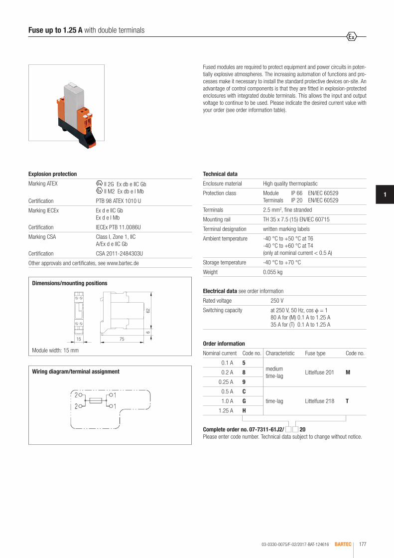
03-0330-0075/F-02/2017-BAT-124616 BARTEC 177
1
Fused modules are required to protect equipment and power circuits in poten-tially explosive atmospheres. The increasing automation of functions and pro-cesses make it necessary to install the standard protective devices on-site. An advantage of control components is that they are fitted in explosion-protected enclosures with integrated double terminals. This allows the input and output voltage to continue to be used. Please indicate the desired current value with your order (see order information table).
Fuse up to 1.25 A with double terminals
Technical data
Enclosure material High quality thermoplastic
Protection class Module IP 66 EN/IEC 60529 Terminals IP 20 EN/IEC 60529
Terminals 2.5 mm2, fine stranded
Mounting rail TH 35 x 7.5 (15) EN/IEC 60715
Terminal designation written marking labels
Ambient temperature -40 °C to +50 °C at T6 -40 °C to +60 °C at T4 (only at nominal current < 0.5 A)
Storage temperature -40 °C to +70 °C
Weight 0.055 kg
Wiring diagram/terminal assignment
Module width: 15 mm
Dimensions/mounting positionsElectrical data see order information
Rated voltage 250 V
Switching capacity at 250 V, 50 Hz, cos ϕ = 1 80 A for (M) 0.1 A to 1.25 A 35 A for (T) 0.1 A to 1.25 A
Explosion protection
Marking ATEX II 2G Ex db e IIC Gb II M2 Ex db e I Mb
Certification PTB 98 ATEX 1010 U
Marking IECEx Ex d e IIC GbEx d e I Mb
Certification IECEx PTB 11.0086U
Marking CSA Class I, Zone 1, IIC A/Ex d e IIC Gb
Certification CSA 2011-2484303U
Other approvals and certificates, see www.bartec.de
Complete order no. 07-7311-61J2/ 20 Please enter code number. Technical data subject to change without notice.
Order information
Nominal current Code no. Characteristic Fuse type Code no.
0.1 A 5medium time-lag
Littelfuse 201 M0.2 A 8
0.25 A 9
0.5 A C
time-lag Littelfuse 218 T1.0 A G
1.25 A H
15 75
626

03-0330-0194/F-02/2017-BAT-201045BARTEC178
Ordering information
Fuse type Littelfuse 218
Nominal current (time-lag) Code no. Nominal current (time-lag) Code no.
0.032 A 1 0.25 A 9
0.050 A 2 0.315 A A
0.063 A 3 0.4 A B
0.08 A 4 0.5 A C
0.1 A 5 0.63 A E
0.125 A 6 0.8 A F
0.16 A 7 1.0 A G
0.2 A 8 1.25 A H
Wiring diagram/terminal assignment
Module width: 15 mm
Dimensions/mounting positions
Fused modules are required to protect equipment and power circuits in poten-tially explosive atmospheres. The increasing automation of functions and pro-cesses make it necessary to install the standard protective devices on-site. An advantage of control components is that they are fitted in explosion-protected enclosures with integrated single terminals. This allows the input and output voltage to continue to be used. Please indicate the desired current value with your order (see order information table).
Fuse up to 1.25 A with single terminals
Technical data
Enclosure material High quality thermoplastic
Protection class Module IP 66 EN/IEC 60529 Terminals IP 20 EN/IEC 60529
Terminals 2.5 mm2, fine stranded
Mounting rail TH 35 x 7.5 (15) EN/IEC 60715
Terminal designation written marking labels
Ambient temperature -40 °C to +50 °C at T6 +40 °C to +60 °C at T4 (only at rated current < 0.5 A)
Storage temperature -40 °C to +70 °C
Weight 0.055 kg
Electrical data see ordering information
Rated voltage 250 V
Switching capacity at 250 V, 50 Hz, cos ϕ = 1 35 A for (T) 0.032 A to 1.25 A
Explosion protection
Marking ATEX II 2G Ex db e IIC Gb II M2 Ex db e I Mb
Certification PTB 98 ATEX 1010 U
Marking IECEx Ex d e IIC GbEx d e I Mb
Certification IECEx PTB 11.0086U
Marking CSA Class I, Zone 1, IIC A/Ex d e IIC Gb
Certification CSA 2011-2484303U
Other approvals and certificates, see www.bartec.de
Complete order no. 07-7311-61J2 / TA0 Please enter code number. Technical data subject to change without notice.
3
4
1
2
3
4
1
2
15 75
626
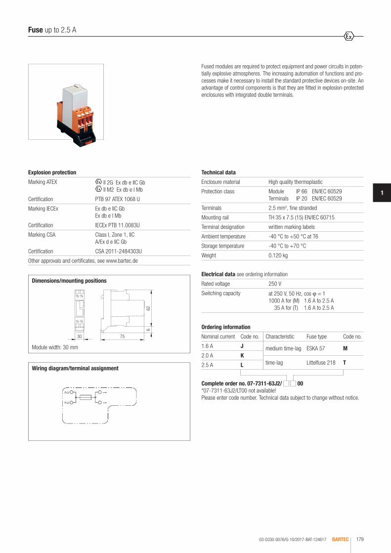
03-0330-0076/G-10/2017-BAT-124617 BARTEC 179
1
22
11
Wiring diagram/terminal assignment
Module width: 30 mm
Dimensions/mounting positions
Fused modules are required to protect equipment and power circuits in poten-tially explosive atmospheres. The increasing automation of functions and pro-cesses make it necessary to install the standard protective devices on-site. An advantage of control components is that they are fitted in explosion-protected enclosures with integrated double terminals.
Fuse up to 2.5 A
Technical data
Enclosure material High quality thermoplastic
Protection class Module IP 66 EN/IEC 60529 Terminals IP 20 EN/IEC 60529
Terminals 2.5 mm2, fine stranded
Mounting rail TH 35 x 7.5 (15) EN/IEC 60715
Terminal designation written marking labels
Ambient temperature -40 °C to +50 °C at T6
Storage temperature -40 °C to +70 °C
Weight 0.120 kg
Electrical data see ordering information
Rated voltage 250 V
Switching capacity at 250 V, 50 Hz, cos ϕ = 1 1000 A for (M) 1.6 A to 2.5 A 35 A for (T) 1.6 A to 2.5 A
Explosion protection
Marking ATEX II 2G Ex db e IIC Gb II M2 Ex db e I Mb
Certification PTB 97 ATEX 1068 U
Marking IECEx Ex db e IIC Gb Ex db e I Mb
Certification IECEx PTB 11.0083U
Marking CSA Class I, Zone 1, IIC A/Ex d e IIC Gb
Certification CSA 2011-2484303U
Other approvals and certificates, see www.bartec.de
Complete order no. 07-7311-63J2/ 00 *07-7311-63J2/LT00 not available!Please enter code number. Technical data subject to change without notice.
Ordering information
Nominal current Code no. Characteristic Fuse type Code no.
1.6 A J medium time-lag ESKA 57 M2.0 A K
time-lag Littelfuse 218 T2.5 A L
30 75
626

03-0330-0417/D-10/2017-BAT-240388BARTEC180
Wiring diagram/terminal assignment
Module width: 30 mm
Dimensions/mounting positions
The increasing automation of functions and processes make it necessary to install the standard protective devices on-site. Fused modules are required to protect equipment and power circuits in potentially explosive atmospheres. An advantage of control components is that they are fitted in explosion-protected enclosures with integrated double terminals.
Fuse up to 6.3 A
Technical data
Enclosure material High quality thermoplastic
Protection class Module IP 66 EN/IEC 60529 Terminals IP 20 EN/IEC 60529
Terminals 2.5 mm2, fine stranded
Mounting rail TH 35 x 7.5 (15) EN/IEC 60715
Terminal designation written marking labels
Ambient temperature -40 °C to +50 °C at T6
Storage temperature -40 °C to +70 °C
Weight 0.250 kg
Electrical data see ordering information
Rated voltage 250 V
Switching capacity at 250 V, 50 Hz, cos ϕ = 1 1000 A for (M) 3.15 A to 6.3 A 35 A for (T) to 3.15 A 40 A for (T) 4 A 50 A for (T) 5 A 63 A for (T) 6.3 A
Explosion protection
Marking ATEX II 2G Ex db e IIC Gb II M2 Ex db e I Mb
Certification PTB 97 ATEX 1068 U
Marking IECEx Ex d e IIC Gb Ex d e I Mb
Certification IECEx PTB 11.0083U
Marking CSA Class I, Zone 1, IIC A/Ex d e IIC Gb
Certification CSA 2011-2484303U
Other approvals and certificates, see www.bartec.de
Complete order no. 07-7311-93J2/ 00 Please enter code number. Technical data subject to change without notice.
Ordering information
Nominal current Code no. Characteristic Fuse type Code no.
3.15 A Mtime-lag ESKA 521 T
4.0 A N
5.0 A P medium time-lag
Multicomp M6.3 A Q
30 75
626

03-0330-0424/D-10/2017-BAT-240842 BARTEC 181
1
Wiring diagram/terminal assignment
Module width: 30 mm
Dimensions/mounting positions
The increasing automation of functions and processes make it necessary to install the standard protective devices on-site. Fused modules are required to protect equipment and power circuits in potentially explosive atmospheres. An advantage of control components is that they are fitted in enclosures with explosion protection with integrated double terminals.
Fuse up to 6.3 A, quick-acting
Technical data
Enclosure material High-quality thermoplastic
Protection class Module IP 66 EN/IEC 60529 Terminals IP 20 EN/IEC 60529
Terminals 2.5 mm2, fine stranded
Mounting rail TH 35 x 7.5 (15) EN/IEC 60715
Terminal designation written marking labels
Ambient temperature -40 °C to +50 °C at T6
Storage temperature -40 °C to +70 °C
Weight 0.250 kg
Electrical data see ordering information
Rated voltage 250 V
Switching capacity at 250 V, 50 Hz, cos ϕ = 1 35 A for 3.15 A 40 A for 4 A 63 A for 6.3 A
Explosion protection
Marking ATEX II 2G Ex db e IIC Gb II M2 Ex db e I Mb
Certification PTB 97 ATEX 1068 U
Marking IECEx Ex d e IIC GbEx d e I Mb
Certification IECEx PTB 11.0083U
Marking CSA Class I, Zone 1, IIC A/Ex d e IIC Gb
Certification CSA 2011-2484303U
Other approvals and certificates, see www.bartec.de
Complete order no.07-7311-93J2/ 00 Please enter code number. Technical data subject to change without notice.
Ordering information
Nominal current Code no. Characteristic Fuse type Code no.
2.5 A L
quick-acting Littelfuse 216 F4.0 A N
6.3 A Q
30 75
626

03-0330-0012/F-02/2017-BAT-106806BARTEC182
Variant 2
Variant 1
Wiring diagram 1/terminal assignment 1
Wiring diagram 2/terminal assignment 2
Module width: 15 mm
Dimensions/mounting position
A freewheeling diode is used as a suppressor circuit. This module can be installed in series or in parallel to an electrical circuit as with a rail-mounted terminal. There are two connection terminals on either side to facilitate wiring to other MODEX modules or direct connection.
Freewheeling diode single
Technical data
Enclosure material High quality thermoplastic
Protection class Module IP 66 EN/IEC 60529 Terminals IP 20 EN/IEC 60529
Terminals 2.5 mm2, fine stranded
Mounting rail TH 35 x 7.5 (15) EN/IEC 60715
Terminal designation written marking labels
Ambient temperature -40 °C to +50 °C at T6 +40 °C to +60 °C at T4
Storage temperature -40 °C to +70 °C
Weight 0.055 kg
Electrical data
Rated voltage 400 V
Diode reverse voltage 1000 V
Diode current 0.7 A Type N4007, other types on request
Explosion protection
Marking ATEX II 2G Ex db e IIC Gb I M2 Ex db e I Mb
Certification PTB 98 ATEX 1010 U
Marking IECEx Ex d e IIC GbEx d e I Mb
Certification IECEx PTB 11.0086U
Marking CSA Class I, Zone 1, IIC A/Ex d e IIC Gb
Certification CSA 2011-2484303U
Other approvals and certificates, see www.bartec.de
Ordering information
Variant 1 07-7311-61GF/5400
Variant 2 07-7311-61GF/5410
Technical data subject to change without notice.
15 75
626

03-0330-0070/C-10/2017-BAT-124611 BARTEC 183
1
2 2 4 4
1 1 3 3
Wiring diagram/terminal assignment
Module width: 30 mm
Dimensions/mounting position
Diode suppressor circuits for electrical and electronic control systems. Spark suppression diodes to prevent overvoltage in inductive loads such as solenoid valves, DC relays, DC valves etc.
Freewheeling diode double
Technical data
Enclosure material high-quality thermoplastic
Protection class Module IP 66 EN/IEC 60529 Terminals IP 20 EN/IEC 60529
Terminals 2.5 mm2, fine stranded
Mounting rail TH 35 x 7.5 (15) EN/IEC 60715
Terminal designation written marking labels
Ambient temperature -25 °C to +60 °C at T4
Storage temperature -40 °C to +70 °C
Weight 0.250 kg
Electrical data
Rated voltage 400 V
Diode reverse voltage 1000 V
Diode current max. 0.6 A,Type N4007 other types on request
Explosion protection
Marking ATEX II 2G Ex db e IIC Gb II M2 Ex db e I Mb
Certification PTB 97 ATEX 1068 U
Marking IECEx Ex d e IIC GbEx d e I Mb
Certification IECEx PTB 11.0083U
Marking CSA Class I, Zone 1, IIC A/Ex d e [ia] IIC Gb
Certification CSA 2011-2484303U
Other approvals and certificates, see www.bartec.de
Ordering information
Freewheeling diode, double 07-7311-63GF/5300
Technical data subject to change without notice.

03-0330-0067/G-02/2017-BAT-124608BARTEC184
Wiring diagram 1/terminal assignment 1
Wiring diagram 2/terminal assignment 2
Dimensions
For general use throughout the field of measuring and control engineering for hazardous areas (e. g. monitoring switching contacts, open circuit monitoring).
Measuring resistor max. 0.8 W
Technical data
Enclosure material High quality thermoplastic
Protection class Module IP 66 EN/IEC 60529 Terminals IP 20 EN/IEC 60529
Terminals 2.5 mm2, fine stranded
Mounting rail TH 35 x 7.5 (15) EN/IEC 60715
Terminal designation written marking labels
Ambient temperature -40 °C to +40 °C at T6 +40 °C to +60 °C at T4
Storage temperature -40 °C to +70 °C
Weight 0.050 kg
Explosion protection
Marking ATEX II 2G Ex db e IIC Gb I M2 Ex db e I Mb
Certification PTB 98 ATEX 1010 U
Marking IECEx Ex d e IIC GbEx d e I Mb
Certification IECEx PTB 11.0086U
Marking CSA Class I, Zone 1, IIC A/Ex d e IIC Gb
Certification CSA 2011-2484303U
Other approvals and certificates, see www.bartec.de
Complete order no. 07-7311-61TW/ 00 Please enter code number. Technical data subject to change without notice.
Ordering information
Resistor pairs Spacing Wiring diagram/ terminal assigment
Code no.
R1 R2
10 kΩ ± 1 % 1 kΩ ± 1 %
Imax. = 6 mA Imax. = 6 mA
None 2 00
R1 R2
3.3 kΩ ± 1 % 1.8 kΩ ± 1 %
Imax. = 8 mA Imax. = 8 mA
None 2 01
R1 4.7 kΩ ± 5 % Imax. = 12 mA None 1 02
R1 120 Ω ± 1 % Imax. = 60 mA None 1 03
R1 1 kΩ ± 1 % Imax. = 25 mA None 1 04
R1 250 Ω ± 0,1 % Imax. = 50 mA None 1 05
R1 R2
2 kΩ ± 1 % 1 kΩ ± 1 %
Imax. = 6 mA None 2 06
R1 R2
249 Ω ± 1 % 100 Ω ± 1 %
Imax. = 50 mA None 2 07
R1 R2
10 kΩ ± 1 % 2 kΩ ± 1 %
Imax. = 6 mA None 2 08
R1 R2
8.2 kΩ ± 1 % 1.5 kΩ ± 1 %
Imax. = 8 mA Imax. = 19 mA
None 2 10
15 75
626

03-0330-0072-08/2014-BAT-124613 BARTEC 185
1
Wiring diagram/terminal assignment
Module width: 75 mm
Dimensions/mounting positions
This module combines a given number of diodes on a single printed board. The diodes are connected to terminals.Typical applications:Lamp test circuits - the signals are connected without reaction. The diodes are connected in pairs and can be wired freely to the anode.
Lamp test circuit
Technical data
Enclosure material High quality thermoplastic
Protection class Module IP 66 EN/IEC 60529 Terminals IP 20 EN/IEC 60529
Terminals 2.5 mm2, fine stranded
Mounting rail TH 35 x 7.5 (15) EN/IEC 60715
Terminal designation written marking labels
Ambient temperature -25 °C to +60 °C at T4
Storage temperature -40 °C to +70 °C
Weight 0.400 kg
Electrical data
Input voltage max. DC 300 V
Reverse voltage 1000 V
Diode current 0.3 A max per lamp, Type 1N4007
Explosion protection
Marking ATEX II 2G Ex db e IIC Gb II M2 Ex db e I Mb
Certification PTB 97 ATEX 1068 U
Marking IECEx Ex d e IIC GbEx d e I Mb
Certification IECEx PTB 11.0083U
Marking CSA Class I, Zone 1, IIC A/Ex d e IIC Gb
Certification CSA 2011-2484303U
Other approvals and certificates, see www.bartec.de
Ordering information
Lamp test circuit 07-7311-97GW/E3K0
Technical data subject to change without notice.

03-0330-0068/H-10/2017-BAT-124609/1BARTEC186
For general use throughout the field of measuring and control engineering for hazardous areas (e. g. monitoring switching contacts on relays, open circuit monitoring).
(Precision) Resistors max 1.2 W
Technical data
Enclosure material High-quality thermoplastic
Protection class Module IP 66 EN/IEC 60529 Terminals IP 20 EN/IEC 60529
Terminals 2.5 mm², fine stranded
Mounting rail TH 35 x 7.5 (15) EN/IEC 60715
Terminal designation written marking labels
Ambient temperature -25 °C to +60 °C at T4
Storage temperature -40 °C to +70 °C
Weight 0.110 kg
Explosion protection
Marking ATEX II 2G Ex db e IIC Gb II M2 Ex db e I Mb
Certification PTB 97 ATEX 1068 U
Marking IECEx Ex d e IIC GbEx d e I Mb
Certification IECEx PTB 11.0083U
Marking CSA Class I, Zone 1, IIC A/Ex d e IIC Gb
Certification CSA 2011-2484303U
Other approvals and certificates, see www.bartec.de
Module width: 30 mm
Wiring diagram 2/terminal assignment 2
Dimensions/mounting positions Wiring diagram 1/terminal assignment 1
Wiring diagram 3/terminal assignment 3

03-0330-0068/H-10/2017-BAT-124609/2 BARTEC 187
1
(Precision) Resistors max 1.2 W
Complete order no. 07-7311-63TW/ Please enter code number. Technical data subject to change without notice.
Ordering information
Rating Spacing Wiring diagram/ terminal assignment
Code no.
R1 4.7 kΩ ± 10 % Imax. = 5 mA R2 10 kΩ ± 10 % Imax. = 5 mA
None 1 01A0
R1 100 Ω ± 1 % Imax. = 50 mA R2 100 Ω ± 1 % Imax. = 50 mA
None 3 0251
R1 2.2 kΩ ± 1 % Imax. = 15 mA R2 680 Ω ± 5 % Imax. = 35 mA
8 mm 3 03A0
R1 680 Ω ± 5 % Imax. = 35 mA None 2 04A0
R1 1 kΩ ± 1 % Imax. = 20 mA R2 10 kΩ ± 1 % Imax. = 5 mA
None 3 05G0
R1 820 Ω ± 5 % Imax. = 35 mA None 2 0600
R1 3.3 kΩ ± 5 % Imax. = 17 mA None 2 0700
R1 2.7 kΩ ± 5 % Imax. = 19 mA None 2 0800
R1 3 kΩ ± 1 % Imax. = 10 mA R2 4.3 kΩ ± 1 % Imax. = 9 mA
None 3 0900
R1 82 Ω ± 1 % Imax. = 70 mA R2 100 Ω ± 1 % Imax. = 60 mA
None 3 1000
R1 120 Ω ± 1 % Imax. = 60 mA R2 150 Ω ± 1 % Imax. = 50 mA
None 3 1100
R1 6.8 kΩ ± 1 % Imax. = 3.5 mA R2 820 Ω ± 1 % Imax. = 29 mA
None 3 1200
R1 680 Ω ± 2 % Imax. = 25 mA R2 3.3 kΩ ± 2 % Imax. = 10 mA
None 1 1300
R1 2.2 kΩ ± 1 % Imax. = 15 mA R2 3.3 kΩ ± 1 % Imax. = 10 mA
None 1 1400
R1 6.8 kΩ ± 1 % Imax. = 9 mA R2 6.8 kΩ ± 1 % Imax. = 9 mA
None 3 1500
R1 3 kΩ ± 1 % Imax. = 10 mA R2 3 kΩ ± 1 % Imax. = 10 mA
None 1 1600
R1 22 kΩ ± 1 % Imax. = 5 mA None 2 17A0
R1 15 kΩ ± 1 % Imax. = 5 mA R2 15 kΩ ± 1 % Imax. = 5 mA
None 3 1800
R1 1.8 kΩ ± 1 % Imax. = 2 mA R2 4.7 kΩ ± 1 % Imax. = 10 mA
None 3 1900
R1 1.5 kΩ ± 1 % Imax. = 19 mA R2 2.2 kΩ ± 1 % Imax. = 16 mA
None 1 2000
R1 8.2 kΩ ± 1 % Imax. = 12 mA R2 1.5 kΩ ± 1 % Imax. = 28 mA
None 3 2100
R1 51.1 kΩ ± 1 % Imax. = 3 mA R2 51.1 kΩ ± 1 % Imax. = 3 mA
None 3 2200

03-0330-0085/E-10/2017-BCS-124626BARTEC188
Wiring diagram/terminal assignment
Module width: 30 mm
Dimensions/mounting positions
The relay modules offer most up-to-date switching configurations. A suppressor diode on the coil protects the power circuit from peak voltages. High shock and vibration resistance is just as important as the IP 66 protection of the contacts. The relay switches circuits up to 5 A and is used as an isolator between low-current control circuits and high-current switching circuits.
Miniature switching relay
Technical data
Enclosure material High-quality thermoplastic
Protection class Module IP 66 EN/IEC 60529 Terminals IP 20 EN/IEC 60529
Terminals 2.5 mm2, fine stranded
Mounting rail TH 35 x 7.5 (15) EN/IEC 60715
Labelling written marking labels
Ambient temperature -40 °C to +40 °C at T6
Storage temperature -40 °C to +70 °C
Weight 0.250 kg
Electrical data
Coil data AC/DC 11.2 V to 16 V/0.53 VA/0.37 W AC/DC 21.5 V to 28 V/0.43 VA/0.33 W AC/DC 42 V to 60.5 V/0.53 VA/0.4 W AC/DC 54 V to 72 V/0.41 VA/0.3 W AC 96 V to 144 V; 50/60 Hz/0.85 VA AC 176 V to 264 V; 50 Hz/1.5 VA
Contact material AgCdO
Max. switching voltage AC 250 V/DC 300 V
Max. switching capacity (ohmic load)
1250 VA (50 W)
Test voltage Coil-contact 4 kV
Mechanical life min. 3 x 10⁶ switching cycles
Electrical life > 1 x 10⁵ switching cycles/AC 220 V, 5 A ohmic load
Switching frequency 7200 switching cycles/h
Explosion protection
Marking ATEX II 2G Ex db e IIC Gb II M2 Ex db e I Mb
Certification PTB 97 ATEX 1068 U
Marking IECEx Ex db e IIC Gb Ex db e I Mb
Certification IECEx PTB 11.0083U
Marking CSA Class I, Zone 1, IIC A/Ex d e IIC Gb
Certification CSA 2011-2484303U
Other approvals and certificates, see www.bartec.de
Ordering information
AC/DC 11.2 V to 16 V 07-7311-6371/2000
AC/DC 21.5 V to 28 V 07-7311-6371/3000
AC/DC 42 V to 60.5 V 07-7311-6371/4000
AC/DC 54 V to 72 V 07-7311-6371/5000
AC 96 V to 144 V 07-7311-6371/7000
AC 176 V to 264 V 07-7311-6371/8000
Technical data subject to change without notice.

03-0330-0014/F-10/2017-BAT-107006/1 BARTEC 189
1
Wiring diagram 1/terminal assignment 1
Wiring diagram 2/terminal assignment 1
Module width: 30 mm
Dimensions/mounting positions
The relay modules offer most up-to-date switching configurations. A suppressor diode on the coil protects the power circuit from peak voltages. The relay is used to switch power circuits up to 6 A. Thanks to its low power consumption it can be controlled by means of electronic circuits, optorelays from BARTEC or standard control circuits.
Relay 1 changeover contact/2 changeover contacts
Technical data
Enclosure material High-quality thermoplastic
Protection class Module IP 66 EN/IEC 60529 Terminals IP 20 EN/IEC 60529
Terminals 2.5 mm2, fine stranded
Mounting rail TH 35 x 7.5 (15) EN/IEC 60715
Labelling written marking labels
Storage temperature -40 °C to +70 °C
Ambient temperature -20 °C to +40 °C
Weight 0.250 kg
Explosion protection
Marking ATEX II 2G Ex db e IIC Gb II M2 Ex db e I Mb
Certification PTB 97 ATEX 1068 U
Marking IECEx Ex db e IIC Gb Ex db e I Mb
Certification IECEx PTB 11.0083U
Marking CSA Class I, Zone 1, IIC A/Ex d e IIC Gb
Certification CSA 2011-2484303U
Other approvals and certificates, see www.bartec.de

03-0330-0014/F-10/2017-BAT-107006/2BARTEC190
Contact data Contact material AgCdO
UA Imax. Pmax. (1 changeover contact)
AC 400 V 2,0 A 0700 VA cos ϕ = 1
AC 250 V 6.0 A 1400 VA ohmic load
DC 125 V 0.6 A 0075 W cos ϕ = 1
DC 050 V 3.0 A 0150 W ohmic load
UA Imax. Pmax. (2 changeover contacts)
AC 400 V 1.0 A0350 VA cos ϕ = 1
AC 250 V 3.0 A0700 VA ohmic load
DC 125 V 0.25 A0030 W cos ϕ = 1
DC 050 V 1.5 A0175 W ohmic load
Relay 1 changeover contact/2 changeover contacts
Complete order no. 07-7311-937 / 000 Relay, 2 changeover contacts also available in AC/DC 48 V.
Order no. 07-7311-9372/4000 Please insert correct code. Technical data subject to change without notice.
Electrical data
Coil data
AC/DC 12 V AC/DC 24 V AC 110 V AC 120 V AC 230/240 V
± 10 % ± 10 % +10 % +10 %/60 Hz + 10 %
0.45 W 0.46 W 1.2 VA 1.0 VA 1.2 VA
0.6 VA 0.56 VA
Making current (16 ms) 20 A (1 changeover contact) 10 A (2 changeover contacts)
Test voltage Coil-contact 4 kV
Mechanical life > 20 x 106 switching cycles
Electrical life > 1 x 10⁵ switching cycles/AC 230 V 6 A ohmic load (1 changeover contact)
> 1 x 10⁵ switching cycles/AC 230 V 3 A ohmic load (2 changeover contacts)
Operating frequency 1800 switching cycles/hOrdering information
Contacts Code no. Voltage Code no.
1 changeover 1AC/DC 12 V 2
AC/DC 24 V 3
AC 110 V 7
2 changeovers 2 AC 120 V/60 Hz H
AC 230 V/240 V 9

03-0330-0089/D-10/2017-BAT-124630 BARTEC 191
1
Wiring diagram/terminal assignment
Module width: 75 mm
Dimensions/mounting positions
Relay modules in the MODEX system offer modern switch features in explosive areas. The MODEX power relay is used to switch load-current circuits to 12 A, e. g. heating circuits or smaller motors.
Power relay
Technical data
Enclosure material High quality thermoplastic
Protection class Module IP 66 EN/IEC 60529 Terminals IP 20 EN/IEC 60529
Terminals 2.5 mm2, fine stranded
Mounting rail TH 35 x 7.5 (15) EN/IEC 60715
Terminal designation written marking labels
Ambient temperature mounted in sequence on TH at ≥ 16 mm spacing -25 °C to +40 °C at T6
Storage temperature -40 °C to +70 °C
Weight 0.500 kg
Electrical data
Coil data DC 24 V ± 10 % AC 230 V ± 10 %
Rated output DC 24 V approx. 1.25 W AC 230 V approx. 1.9 VA
Contact material Contact material AgCdO
Max. switching voltage AC 400 V
Max. switching current (ohmic load)
12 A
Max. switching capacity (ohmic load)
4560 VA
Test voltage Coil contact 2.5 kV effective 15/10 ms
Mechanical life 20 x 106 switching cycles
Switching frequency 6000 switching cycles/h without load 1000 switching cycles/h at nominal load
Explosion protection
Marking ATEX II 2G Ex db e IIC Gb II M2 Ex db e I Mb
Certification PTB 97 ATEX 1068 U
Marking IECEx Ex d e IIC GbEx d e I Mb
Certification IECEx PTB 11.0083U
Marking CSA Class I, Zone 1, IIC A/Ex d e IIC Gb
Certification CSA 2011-2484303U
Other approvals and certificates, see www.bartec.de
Ordering information
DC 24 V 07-7311-9772/3310
AC 230 V 07-7311-9772/H310
Technical data subject to change without notice.
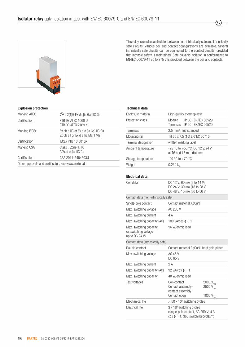
03-0330-0088/G-08/2017-BAT-124629/1BARTEC192
This relay is used as an isolator between non-intrinsically safe and intrinsically safe circuits. Various coil and contact configurations are available. Several intrinsically safe circuits can be connected to the contact circuits, provided that intrinsic safety is maintained. Safe galvanic isolation in conformance to EN/IEC 60079-11 up to 375 V is provided between the coil and contacts.
Isolator relay galv. isolation in acc. with EN/IEC 60079-0 and EN/IEC 60079-11
Technical data
Enclosure material High-quality thermoplastic
Protection class Module IP 66 EN/IEC 60529 Terminals IP 20 EN/IEC 60529
Terminals 2.5 mm2, fine stranded
Mounting rail TH 35 x 7.5 (15) EN/IEC 60715
Terminal designation written marking label
Ambient temperature -25 °C to +55 °C (DC 12 V/24 V) at T6 and 15 mm distance
Storage temperature -40 °C to +70 °C
Weight 0.250 kg
Electrical data
Coil data DC 12 V; 60 mA (9 to 14 V) DC 24 V; 30 mA (18 to 28 V) DC 48 V; 15 mA (36 to 56 V)
Contact data (non-intrinsically safe)
Single-pole contact Contact material AgCuNi
Max. switching voltage AC 250 V
Max. switching current 4 A
Max. switching capacity (AC) 100 VA/cos φ = 1
Max. switching capacity (at switching voltage up to DC 24 V)
96 W/ohmic load
Contact data (intrinsically safe)
Double contact Contact material AgCuNi, hard gold plated
Max. switching voltage AC 46 V DC 65 V
Max. switching current 2 A
Max. switching capacity (AC) 92 VA/cos φ = 1
Max. switching capacity 48 W/ohmic load
Test voltages Coil-contact 5000 Vrms Contact assembly- 2500 Vrms contact assembly Contact open 1000 Vrms
Mechanical life > 50 x 106 switching cycles
Electrical life 3 x 10⁵ switching cycles (single-pole contact, AC 250 V; 4 A; cos φ = 1; 360 switching cycles/h)
Explosion protection
Marking ATEX II 2(1)G Ex de [ia Ga] IIC Ga
Certification PTB 97 ATEX 1068 U PTB 03 ATEX 2169 X
Marking IECEx Ex db e IIC or Ex d e [ia Ga] IIC GaEx db e I or Ex d e [ia Ma] I Mb
Certification IECEx PTB 13.0016X
Marking CSA Class I, Zone 1, IIC A/Ex d e [ia] IIC Ga
Certification CSA 2011-2484303U
Other approvals and certificates, see www.bartec.de
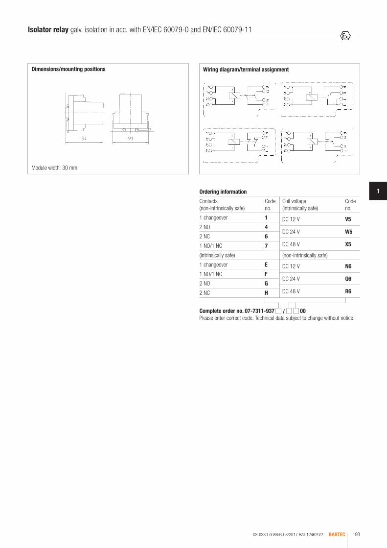
03-0330-0088/G-08/2017-BAT-124629/2 BARTEC 193
1
Isolator relay galv. isolation in acc. with EN/IEC 60079-0 and EN/IEC 60079-11
Complete order no. 07-7311-937 / 00 Please enter correct code. Technical data subject to change without notice.
Ordering information
Contacts (non-intrinsically safe)
Code no.
1 changeover 1
2 NO 4
2 NC 6
1 NO/1 NC 7
(non-intrinsically safe)
DC 12 V N6
DC 24 V Q6
DC 48 V R6
Coil voltage (intrinsically safe)
Code no.
DC 12 V V5
DC 24 V W5
DC 48 V X5
Wiring diagram/terminal assignment
(intrinsically safe)
1 changeover E
1 NO/1 NC F
2 NO G
2 NC H
Module width: 30 mm
Dimensions/mounting positions

BARTEC194 03-0330-0028/K-01/2017-BAT-108406/1
NoteFor use with inductive loads the relays can be connected with an effective sup-pressor in order to protect the contacts.
Cradle relay for alternating voltage, neutral, monostable. High-quality cradle relays for AC are installed as encapsulated flameproof elements in the MODEX enclosure. The IP 66 protection class ensures that the contacts are also pro-tected from aggressive atmospheres.
Applications:switching of measuring and control circuits in industrial areas.
Cradle relay AC
Technical data
Enclosure material High-quality thermoplastics
Protection class Module IP 66 EN/IEC 60529 Terminals IP 20 EN/IEC 60529
Terminals 2.5 mm2, fine stranded
Mounting rail TH 35 x 7.5 (15) EN/IEC 60715
Terminal designation written marking labels
Ambient temperature -25 °C to +50 °C at T6 mounted in sequence on TH at 5 mm spacing
Storage temperature -40 °C to +70 °C
Weight 0.500 kg
Electrical data
Operating data (coil circuit)
UN IN (8 contact decks)
AC 110 V 25 mA
AC 120 V/50 Hz 28 mA
AC 120 V/60 Hz 25 mA
AC 220 V 13 mA
AC 230/240 V 13 mA
Contact data Switching voltage: UA max. = AC/DC 125 V Switching current: Imax. = 1 A (per contact)
Switching capacity Pmax. = 40 W/50 VA
Contact material silver, gold-flashed
Contact arrangement 4 changeovers; 8 NO; 4 NO/4 NC
Other datas AC types
Max. switching frequency 20 (switching cycles/sec.)
Mech. service life approx. 107 (switching cycles)
Test voltage coil/contact (V~ rms ) 500 at UN < 60 V, 2 000 at UN > 60 V
500 contact/contact (V~ rms )
Explosion protection
Marking ATEX II 2G Ex db e IIC Gb I M2 Ex db e I Mb
Certification PTB 97 ATEX 1068 U
Marking IECEx Ex db e IIC or Ex d e IIC GbEx db e I or Ex d e I Mb
Certification IECEx PTB 11.0083U
Other approvals and certificates, see www.bartec.de
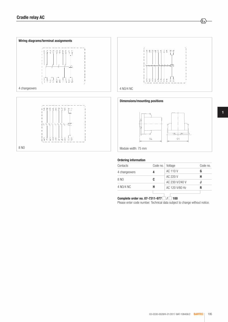
03-0330-0028/K-01/2017-BAT-108406/2 BARTEC 195
1
Wiring diagrams/terminal assignments
4 changeovers 4 NO/4 NC
Dimensions/mounting positions
8 NO Module width: 75 mm
Cradle relay AC
Complete order no. 07-7311-977 / 100 Please enter code number. Technical data subject to change without notice.
Ordering information
Contacts Code no.
4 changeovers 4
8 NO C
4 NO/4 NC H
Voltage Code no.
AC 110 V G
AC 220 V H
AC 230 V/240 V J
AC 120 V/60 Hz R

03-0330-0028/K-01/2017-BAT-108406/3BARTEC196
NoteFor use with inductive loads the relays can be connected with an effective sup-pressor in order to protect the contacts.
Cradle relay for direct voltage, neutral, monostable. High-quality cradle relays for DC are installed as encapsulated flameproof elements in the MODEX enclo-sure. The IP 66 protection class ensures that the contacts are also protected from aggressive atmospheres.
Applications:switching of measuring and control circuits in industrial areas.
Cradle relay DC
Technical data
Enclosure material High-quality thermoplastics
Protection class Module IP 66 EN/IEC 60529 Terminals IP 20 EN/IEC 60529
Terminals 2.5 mm2, fine stranded
Mounting rail TH 35 x 7,5 (15) EN/IEC 60715
Terminal designation written marking labels
Ambient temperature -25 °C to +55 °C at T6
Storage temperature -40 °C to +70 °C
Weight 0.500 kg
Electrical data
Operating data (coil circuit)
UN IN (8 contact decks)
DC 15 V 60 mA
DC 24 V 27 mA
DC 48 V 17 mA
Contact data Switching voltage: UA max. = AC/DC 125 V Switching current: Imax. = 1 A (per contact)
Switching capacity Pmax. = 40 W/50 VA
Contact material silver, gold-flashed
Contact arrangement 4 changeovers; 8 NO; 4 NO/4 NC
Other datas DC types
Max. switching frequency 50 (switching cycles/sec.)
Mech. service life approx. 108 (switching cycles)
Test voltage 500 coil/contact (V~ rms )
500 contact/contact (V~rms )
Explosion protection
Marking ATEX II 2G Ex db e IIC Gb I M2 Ex db e I Mb
Certification PTB 97 ATEX 1068 U
Marking IECEx Ex db e IIC or Ex d e IIC GbEx db e I or Ex d e I Mb
Certification IECEx PTB 11.0083U
Marking CSA Class I, Zone 1, IIC A/Ex d e IIC Gb
Certification CSA 2011-2484303
Other approvals and certificates, see www.bartec.de

03-0330-0028/K-01/2017-BAT-108406/4 BARTEC 197
1
Wiring diagrams/terminal assignments
4 changeovers 4 NO/4 NC
Dimensions/mounting positions
8 NO Module width: 75 mm
Cradle relay DC
Complete order no. 07-7311-977 / 100 Please enter code number. Technical data subject to change without notice.
Ordering information
Contacts Code no.
4 changeovers 4
8 NO C
4 NO/4 NC H
Voltage Code no.
DC 15 V 8
DC 24 V 3
DC 48 V 4
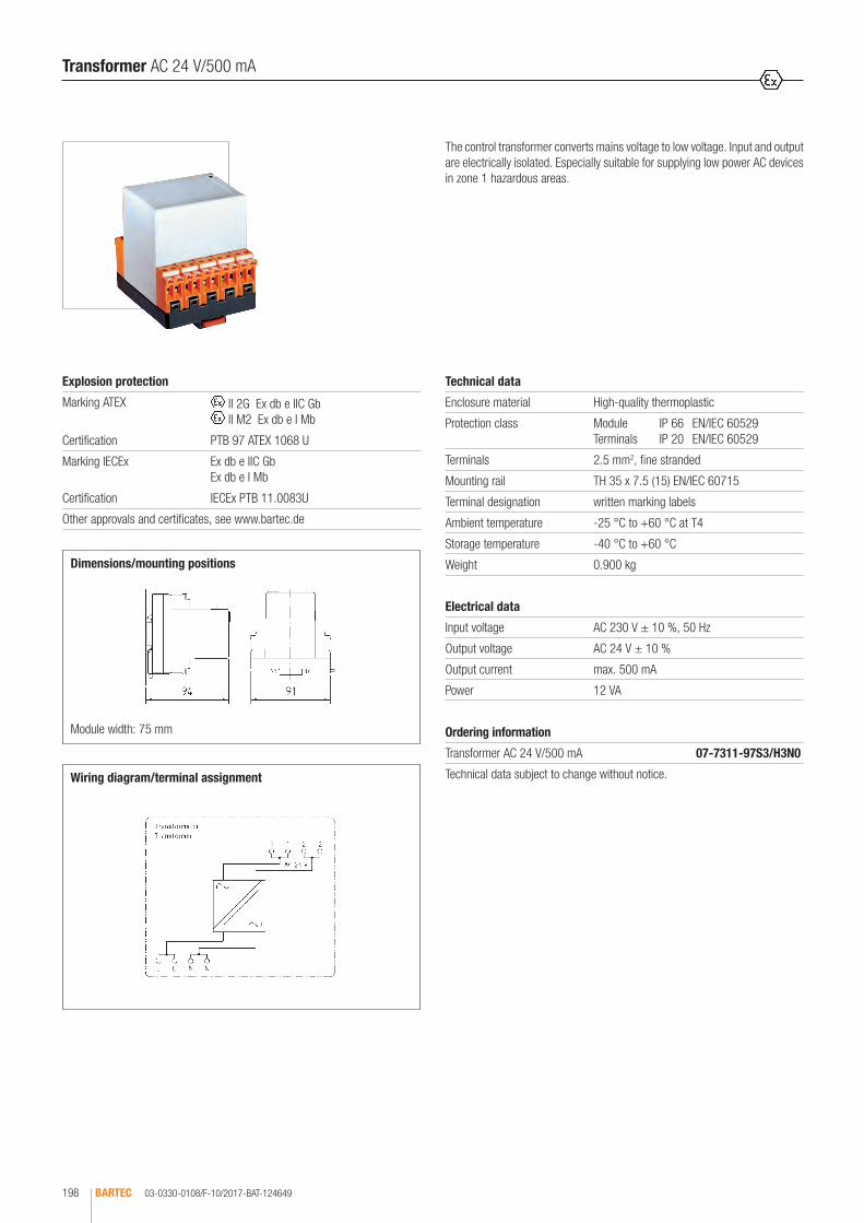
03-0330-0108/F-10/2017-BAT-124649BARTEC198
Wiring diagram/terminal assignment
Module width: 75 mm
Dimensions/mounting positions
The control transformer converts mains voltage to low voltage. Input and output are electrically isolated. Especially suitable for supplying low power AC devices in zone 1 hazardous areas.
Transformer AC 24 V/500 mA
Technical data
Enclosure material High-quality thermoplastic
Protection class Module IP 66 EN/IEC 60529 Terminals IP 20 EN/IEC 60529
Terminals 2.5 mm2, fine stranded
Mounting rail TH 35 x 7.5 (15) EN/IEC 60715
Terminal designation written marking labels
Ambient temperature -25 °C to +60 °C at T4
Storage temperature -40 °C to +60 °C
Weight 0.900 kg
Electrical data
Input voltage AC 230 V ± 10 %, 50 Hz
Output voltage AC 24 V ± 10 %
Output current max. 500 mA
Power 12 VA
Explosion protection
Marking ATEX II 2G Ex db e IIC Gb II M2 Ex db e I Mb
Certification PTB 97 ATEX 1068 U
Marking IECEx Ex db e IIC GbEx db e I Mb
Certification IECEx PTB 11.0083U
Other approvals and certificates, see www.bartec.de
Ordering information
Transformer AC 24 V/500 mA 07-7311-97S3/H3N0
Technical data subject to change without notice.
Weitere Zulassungen und Prüfbescheinigungen finden Sie unter www.bartec.de
Other approvals and certificates, see www.bartec.de
Autres agréments et certificats, voir www.bartec.de
Другие сертификаты и сертификаты, см. www.bartec.de
Consulte otras homologaciones y certificados de ensayo en www.bartec.de
Outras homologações e certificados de teste encontram-se em www.bartec.de
Diğer onay ve sertifikalar için bkz: www.bartec.de
BestellangabenOrdering informationLes informations de commandeДанные для заказаDatos del pedidoDados para encomendaSipariş bilgileri

03-0330-0109/E-10/2017-BAT-124650 BARTEC 199
1
Wiring diagram/terminal assignment
Module width: 75 mm
Dimensions/mounting positions
The power supply module is ideal for control systems in measurement and control technology and for Ex d load with DC connection. The power supply unit has a stabilzed output and offers short-circuit protection.
AC/DC converter DC 24 V/450 mA
Technical data
Enclosure material High-quality thermoplastic
Protection class Module IP 66 EN/IEC 60529 Terminal IP 20 EN/IEC 60529
Mounting rail TH 35 x 7.5 (15) EN/IEC 60715
Terminal designation written marking labels
Ambient temperature -20 °C to +40 °C at T6
Storage temperature -40 °C to +70 °C
Weight 0.400 kg
Electrical data
Input voltage AC 24 V + 15 % - 5 %, 50/60 Hz
Output voltage DC 24 V ± 5 %
Output current 450 mA
Power dissipation ≤ 2.5 W
Residual ripple ≤ 20 mVSS
Power consumption max. 13 W
Explosion protection
Marking ATEX II 2G Ex db e IIC Gb II M2 Ex db e I Mb
Certification PTB 97 ATEX 1068 U
Marking IECEx Ex db e IIC GbEx db e I Mb
Certification IECEx PTB 11.0083U
Marking CSA Class I, Zone 1, IIC A/Ex d e IIC Gb
Certification CSA 2011-2484303U
Other approvals and certificates, see www.bartec.de
Ordering information
AC/DC converter, DC 24 V/450 mA 07-7311-97S7/AAMO
Technical data subject to change without notice.

03-0330-0324/B-10/2017-BAT-217131BARTEC200
BARTECNetzteil DC 24 V/2 A
Wiring diagram/terminal assignment
Dimensions/mounting positions
This power supply unit with wide-range input is suitable for universal use. The DC output voltage is stabilised, galvanically isolated and permanently protected against short-circuits.
Power supply unit DC 24 V/2 A
Electrical data
Supply voltage AC 110 to 250 V, 47 to 63 Hz
Input voltage range AC 94 to 265 V
Nominal input current 0.6 A at AC 230 V/1.1 A at AC 120 V
Power consumption Pmax. = 66 W
Power dissipation PV tot. = 7.3 W
Galvanic isolation Input//Output
Display Operation LED green Overload > 3 A or short-circuit LED green flashing
Outputs
Output voltage DC 24 V +/-3 %
Output current 2 A at Tu < +50 °C
Power derating 2.5 %/K > +50 °C
Nominal output power Pa = 48 W
Residual ripple < 50 mV at Tu = -10 °C to +60 °C
Protection and monitoring Permanent short-circuit protection, overload proof
Note: At least 40 mm clearance must be left around the power supply unit.
Explosion protection
Marking ATEX II 2G Ex db e IIC Gb II M2 Ex db e I Mb
Certification PTB 97 ATEX 1066 U
Marking IECEx Ex db e IIC GbEx db e I Mb
Certification IECEx PTB 11.0082U
Marking CSA Class I, Zone 1, IIC A/Ex d e IIC Gb
Certification CSA 2011-2484303U
Other approvals and certificates, see www.bartec.de
Ordering information
Power supply unit, DC 24 V/2 A 07-7331-1201/0000
Technical data subject to change without notice.
BARTECPower supply unit DC 24 V/2 A
Technical data
Construction Flameproof, clip-on enclosure for TH 35 rail
Enclosure material High-quality thermoplastic
Protection class Module IP 66 EN/IEC 60529 Terminals IP 20 EN/IEC 60529 Terminals with cover IP 30 EN/IEC 60529
Terminals 2.5 mm², fine stranded
Terminal designation written marking labels
Display LEDs on front panel
Ambient temperature -25 °C to +60 °C at T4
Storage temperature -25 °C to +60 °C
Weight 2.1 kg

03-0330-0106/E-10/2017-BAT-124647 BARTEC 201
1
Wiring diagram 1/terminal assignment 1
Wiring diagram 2/terminal assignment 2
Module width: 75 mm
Dimensions/mounting positions
This power supply unit is suitable for universal use with either AC or DC voltage on the input side. The DC output voltage is stabilised and short-circuit and overload proof to a limited extent. An additional output circuit protection is recommended.
Power supply unit AC/DC 110 to 250 V
Technical data
Enclosure material High-quality thermoplastic
Protection class Module IP 66 EN/IEC 60529 Terminals IP 20 EN/IEC 60529
Terminals 2.5 mm2, fine stranded
Mounting rail TH 35 x 7.5 (15) EN/IEC 60715
Terminal designation written marking labels
Ambient temperature mounted on rail with 8 mm spacing -20 °C to +40 °C at T6
Storage temperature -20 °C to +65 °C
Weight 0.600 kg
Complete order no. 07-7311-97S9/J 0 Please enter code number. Technical data subject to change without notice.
Electrical data see ordering information
Input voltage DC 110 V to max. 320 V AC 100 V to max. 250 V 50/60 Hz
Residual ripple max. 150 mVSS
Power dissipation max. 3 W
Ordering information
Output voltage Output current Code no.
DC 12 V ± 5 % 440 mA 5L
DC 24 V ± 5 % resp. DC +12 V/-12 V ± 5 %
220 mA ± 220 mA
6G
Explosion protection
Marking ATEX II 2G Ex db e IIC Gb II M2 Ex db e I Mb
Certification PTB 97 ATEX 1068 U
Marking IECEx Ex d e IIC GbEx d e I Mb
Certification IECEx PTB 11.0083U
Marking CSA Class I, Zone 1, IIC A/Ex d e IIC Gb
Certification CSA 2011-2484303U
Other approvals and certificates, see www.bartec.de
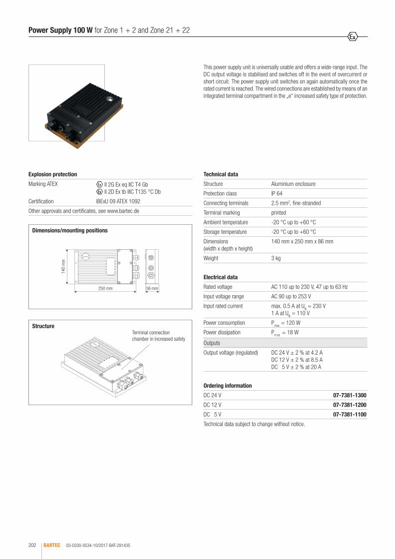
03-0330-0534-10/2017-BAT-291435BARTEC202
Dimensions/mounting positions
140
mm
250 mm 56 mm
Structure
This power supply unit is universally usable and offers a wide-range input. The DC output voltage is stabilised and switches off in the event of overcurrent or short circuit. The power supply unit switches on again automatically once the rated current is reached. The wired connections are established by means of an integrated terminal compartment in the „e“ increased safety type of protection.
Power Supply 100 W for Zone 1 + 2 and Zone 21 + 22
Technical data
Structure Aluminium enclosure
Protection class IP 64
Connecting terminals 2.5 mm2, fine-stranded
Terminal marking printed
Ambient temperature -20 °C up to +60 °C
Storage temperature -20 °C up to +60 °C
Dimensions (width x depth x height)
140 mm x 250 mm x 86 mm
Weight 3 kg
Electrical data
Rated voltage AC 110 up to 230 V, 47 up to 63 Hz
Input voltage range AC 90 up to 253 V
Input rated current max. 0.5 A at UN = 230 V 1 A at UN = 110 V
Power consumption Pmax. = 120 W
Power dissipation PV tot. = 18 W
Outputs
Output voltage (regulated) DC 24 V ± 2 % at 4.2 A DC 12 V ± 2 % at 8.5 A DC 15 V ± 2 % at 20 A
Explosion protection
Marking ATEX II 2G Ex eq IIC T4 Gb II 2D Ex tb IIIC T135 °C Db
Certification IBExU 09 ATEX 1092
Other approvals and certificates, see www.bartec.de
Terminal connection chamber in increased safety
Weitere Zulassungen und Prüfbescheinigungen finden Sie unter www.bartec.de
Other approvals and certificates, see www.bartec.de
Autres agréments et certificats, voir www.bartec.de
Другие сертификаты и сертификаты, см. www.bartec.de
Consulte otras homologaciones y certificados de ensayo en www.bartec.de
Outras homologações e certificados de teste encontram-se em www.bartec.de
Diğer onay ve sertifikalar için bkz: www.bartec.de
Ordering information
DC 24 V 07-7381-1300
DC 12 V 07-7381-1200
DC 55 V 07-7381-1100
Technical data subject to change without notice.

03-0330-0416/D-10/2017-BAT-240326 BARTEC 203
1
Ordering information
Optocoupler, 2-channel 07-7311-93QH/C5M0
Technical data subject to change without notice.
This optocoupler provides for a safe galvanic isolation between a non-intrinsi-cally safe input circuit (transmitter) and the output connected to an intrinsically safe circuit (receiver), which is clearly identified by means of light blue terminals. The two channels are also safely galvanically isolated from each other.
Optocoupler 2-channel
Technical data
Enclosure material High-quality thermoplastic
Protection class Module IP 54 EN/IEC 60529 Terminals IP 20 EN/IEC 60529
Terminals Max. 2.5 mm2, fine stranded
Mounting rail TH 35 x 7.5 (15) EN/IEC 60715
Terminal designation written marking labels
Ambient temperature -20 °C to +40 °C at T6
Storage temperature -40 °C to +70 °C
Weight 0.250 kg
Electrical data
Total power dissipation Pmax. = 0.8 W No capacities and inductances
Inputs
Input voltage DC 20 to 28 V (with reverse polarity protection)
Input current 5.5 mA to 9.2 mA
Outputs
Voltage DC 4 V to max. 30 V
Saturation voltage 0.9 V
Current max. 50 mA (only for connecting to certified intrinsically safe circuits. Ci and Li negligible)
Transmission data
Switching frequency max. 5 kHz (with UA = 10 V)
Switching times measured at UE = 20 VSS; UA = 10 VSS; IA = 50 mA
Rise time approx. 15 µs Drop-out time approx. 13 µs Switch-on time approx. 18 µs Switch-off time approx. 19 µs
Galvanic isolation transmitter/receiver
max. 375 V (peak value)
Explosion protection
Marking ATEX II 2G Ex db e [ia Ga] IIC Gb I M2 Ex db e [ia Ma] I Mb
Certification PTB 97 ATEX 1068 U TÜV 01 ATEX 1715
Marking IECEx Ex db e [ia Ga] IIC Gb Ex db e [ia Ma] I Mb
Certification IECEx PTB 11.0083U IECEx TUN 11.0029X
Marking CSA Class I, Zone 1, IIC A/Ex d e [ia] IIC Gb
Certification CSA 2011-2484303U
Fitting Type 17-9135-4.../.... II (1) G / II (1) D
[Ex ia Ga] IIC [Ex ia Da] IIIC
Other approvals and certificates, see www.bartec.de
Module width: 30 mm
Dimensions/mounting positions
Wiring diagram/terminal assignment

03-0330-0128/E-10/2017-BAT-127171/1BARTEC204
4 NAMUR sensors, optocouplers, mechanical contacts or other operating elements can be connected to the isolator amplifier in an intrinsically safe way.The intrinsically safe inputs are safely galvanically isolated from the supply voltage and the outputs in accordance with EN/IEC 60079-11. Open and short circuits on the sensor lines are detected and signalled via an additional transistor output as group fault signal. LEDs display the output states.
Isolator amplifier 4-channel with display
Technical data
Construction Flameproof, clip-on enclosure for TH 35 rail
Enclosure material High-quality thermoplastics
Protection class Module IP 66 EN/IEC 60529 Terminals IP 20 EN/IEC 60529 Terminals with cover IP 30 EN/IEC 60529
Terminals 2.5 mm², fine stranded
Mounting rail TH 35 x 7.5 (15) EN/IEC 60715
Terminal designation written marking labels
Ambient temperature -20 °C to +50 °C
Storage temperature -40 °C to +60 °C
Weight 0.640 kg
Explosion protection
Marking ATEX II 2G Ex db e IIC Gb II M2 Ex db e I Mb
Certification PTB 97 ATEX 1068 U TÜV 97 ATEX 1211 X
Marking IECEx Ex db e [ia Ga] IIC Gb Ex db e [ia Ma] I Mb
Certification IECEx PTB 11.0083U IECEx TUN 11.0027X
Marking CSA Class I, Zone 1, IIC A/Ex d e [ia] IIC Gb
Certification CSA 2011-2484303U
Fitting Type 17-5521-4.../.... II (1) G / II (1) D
[Ex ia Ga] IIC [Ex ia Da] IIIC
Um = 253 V I0 = 30 mA U0 = 11.55 V P0 = 86.4 mW
Other approvals and certificates, see www.bartec.de
Electrical data
Supply voltage DC 20 V to DC 30 V
Power consumption max. 580 mA
Power dissipation PV = max. 2.4 W
Galvanic isolation Inputs//power supply, outputs
Inputs
Voltage Ua = 8.2 V
Switching thresholds open circuit < 0.26 mA damped < 1.2 mA undamped > 2.1 mA short circuit > 7.4 mA
Outputs
Transistor outputs output current channel max. 100 mA signal level 1 - signal = Ub - 1 V 0 - signal = 0.9 VSwitching frequency 1.5 kHz
Displays LED’s for all outputs
Line monitoring always active, separate fault signal output
Notes
• Observe the terminal assignment
• Transistor output is not short-circuit proof
• For open/short-circuit monitoring with contact scan, use 1 kΩ/10 kΩ resistive coupling element; Type 17-9Z62-0002

03-0330-0128/E-10/2017-BAT-127171/2 BARTEC 205
1
Complete order no. 07-7311-97MT/BA Please insert correct code. Technical data subject to change without notice.
Isolator amplifier 4-channel with display
Status chart
Input B/S Out B/S Out B/S Out
damped 0 1 0 0 1 1
undamped 0 0 0 1 1 0
open circuit 1 1 1 0 0 1
short circuit 1 0 1 1 0 0
Code no. 12 22 32
Wiring diagram/terminal assignment
Module width: 75 mm
Dimensions/mounting positions

03-0330-0122/F-10/2017-BAT-126575BARTEC206
The MODEX series includes a temperature measuring transducer mounted on-site in the same way as a rail-mounted terminal. The module transforms the signal received from the Pt100 temperature sensor into a proportional, load-in-dependent 4 to 20 mA output signal. The sensor circuit is intrinsically safe according to Ex protection type Ex ia. An output current exceeding the 4 to 20 mA range signals a senor fault (open/short circuit). The Pt100 temperature sensor can be operated in 2-wire or 3-wire circuits in Zone 0 or Zone 1.
Measuring transducer for Pt100, galvanically isolated
Technical data
Enclosure material High-quality thermoplastic
Protection class Module IP 66 EN/IEC 60529 Terminals IP 20 EN/IEC 60529
Terminals 2.5 mm2, fine stranded
Mounting rail TH 35 x 7.5 (15) EN/IEC 60715
Terminal designation written marking labels
Ambient temperature -40 °C to +60 °C at T4
Storage temperature -40 °C to +60 °C
Weight 0.250 kg
Electrical data
Operating voltage DC 24 V -10 %, +20 %
Power consumption 1.6 W
Sensor Pt100 temperature sensor 2- or 3-wire circuits
Output Load independent current: 4 to 20 mA Max. load: ≤ 400 Ω
Temperature range -50 °C to +100 °C 0 °C to +200 °C 0 °C to +400 °C
Accuracy ± 1 % of upper value
Function test Connect 100 Ω resistance to terminal 15 - 16 and bridge terminals 16 and 17. Apply current between L- and terminal 31. Note: Observe terminal assignment.
Explosion protection
Marking ATEX II 2G Ex db e IIC Gb II M2 Ex db e I Mb
Certification PTB 97 ATEX 1068 U TÜV 97 ATEX 1204 X
Marking IECEx Ex db e [ia Ga] IIC/IIB Gb Ex db e [ia Ma] I Mb
Certification IECEx PTB 11.0083U IECEx TUN 11.0030X
Marking CSA Class I, Zone 1, IIC A/Ex d e [ia] IIC Gb
Certification CSA 2011-2484303U
Other approvals and certificates, see www.bartec.de
Fitting Pt100 measuring transducer Type 17-6582-1.../.... II (1)G [Ex ia Ga] IIC/IIB II (1)D [Ex ia Da] IIIC/IIIB
Safety data Um = 253 V I0 = 12 mA U0 = 17.3 V P = 51.9 mW
Ex ia IIC IIB
L0 (mH) ≤ 200 800
C0 (nF) ≤ 341 2048
Wiring diagram/terminal assignment
Module width: 30 mm
Dimensions/mounting positions
Pt100
Pt10024 V
4...20 mA
0 V
L+ Z7+
Z6
1516
17
Z3Z1
Z2
L- TZ5Z4
-
Ordering information
-50 °C to +100 °C 07-7311-93T5/5350
0 °C to +200 °C 07-7311-93T5/7350
0 °C to +400 °C 07-7311-93T5/9350
0 °C to +150 °C 07-7311-93T5/A350
Technical data subject to change without notice.

03-0330-0105/D-10/2017-BAT-124646 BARTEC 207
1
Wiring diagram/terminal assignment
Module width: 75 mm
Dimensions/mounting positions
MODEX controller module for more up-to-date switching convenience in a potentially explosive atmosphere. The standard two-position controller monitors limit values (limit monitor). The analog input signal is compared with the po-tentiometer setpoint. A floating relay changeover contact is provided as output. The two-point controller is available with optional overcurrent/undercurrent detection, current output and signalling relay. The current output enables you to loop further devices (input current mirror) up to a total load of 400 Ω into the power circuit (4 to 20 mA).
Two-position controller
Technical data
Enclosure material High-quality thermoplastic
Protection class Module IP 66 EN/IEC 60529 Terminals IP 20 EN/IEC 60529
Terminals 2.5 mm2, fine stranded
Mounting rail TH 35 x 7.5 (15) EN/IEC 60715
Terminal designation written marking labels
Ambient temperature mounted on rail with spacing ≥ 16 mm: -20 °C to +40 °C
Storage temperature -40 °C to +60 °C
Weight 0.500 kg
Electrical data
Supply voltage DC 24 V + 15 %
Rated output max. 2.5 W
Input signal 0 to 35 mA ≤ 3.5 mA - undercurrent ≥ 25 mA - overcurrent 4 to 20 mA = 0 to 100 % Load: 200 Ω
Hysteresis 2 mA
Repeat accuracy ± 0.5 % of under range limit (20 mA)
Ambient temperature Influence: ≤ 0.008 %/K
Outputs Relay output: Load: AC 250 V, 3 A, 750 VA
Optional Signal relay: AC 250 V, 1 A, 250 VA Sensor fault relay: AC 250 V, 1 A, 250 VA Current output: 4 to 20 mA Load: 400 Ω
Explosion protection
Marking ATEX II 2G Ex db e IIC Gb I M2 Ex db e I Mb
Certification PTB 97 ATEX 1068 U
Marking IECEx Ex db e IIC oder Ex d e IIC GbEx db e I oder Ex d e I Mb
Certification IECEx PTB 11.0083U
Marking CSA Class I, Zone 1, IIC A/Ex d e [ia] IIC Gb
Certification CSA 2011-2484303U
Other approvals and certificates, see www.bartec.de
Ordering information
Standard 07-7311-97ER/3100
With short circuit/open circuit detection of current output and signal relay
07-7311-97ER/3150
Technical data subject to change without notice.


TABLETS/TABLET PCS FOR INDUSTRY


CONTENT
Agile X IS Industry Tablet PC 10.1" for Zone 1 17-A1B4-1..1/221.1.00
212 - 213
Accessories Agile X IS 00-..; 03-..; 17-..
214 - 217
Agile X Industry Tablet PC 10.1" B7-A234-40.1/111...00
218 - 219
HART Add-on module for Agile X tablet PC 17-A1Z0-0005; G7-A0Z0-0007; B7-A2Z0-0033
220
RFID UHF Add-on module for Agile X tablet PC B7-A2Z0-0032
221
Accessories Agile X 00-..; 03-..; B7-..
222 - 226
Lumen X7
Industry Tablet PC
B7-A234-2043/44330000; B7-A234-2343/44330000
227 - 228
Accessories Lumen X7 00-..; 03-..; 17-..; B7-..
229 - 230

03-0330-0499-05/2017-BAT-408342/1BARTEC212
The BARTEC Agile X IS is an rugged and highly flexible industrial tablet PC for rough environments. Agile X IS has a large number of international certifica-tions and can be used throughout the world. It is certified for ATEX and IECEx Zone 1 and UL Class I Division 1. Further national certifications are possible on customer request. Thanks to its broad range of functions, the Agile X IS is the perfect assistant to service technicians, engineers and project managers in the field and in industry.
Agile X IS Industry Tablet PC 10.1" for Zone 1
Explosion protection
Marking ATEX Zone 1 II 2G Ex ia op is IIC T4 Gb
-20 °C ≤ Ta ≤ +50 °C
Certification DEMKO 16 ATEX 1803
Marking IECEx Zone 1 Ex ia IIC op is T4 Gb -20 °C ≤ Ta ≤ +50 °C
Certification IECEx UL 16.0160
Marking UL UL Class I Division 1 Class I, Division 1, Groups A, B, C and D
UL Zone 1 Class I, Division 1, Groups A, B, C and D; Class I, Zone 1, AEx ia IIC T4 Gb -20 °C ≤ Ta ≤ +50 °C
Certification (US and Canada)
E226123
Technical data
Processor Intel N3710 1.6 GHz (turbo 2.56 GHz)
RAM 8 GB SODIM DDR3L-1600
Mass storage 128 GB SATA uSSD
Operating system Windows® 10 IoT Enterprise CBB Windows® Embedded 8.1 Industry Pro
Panel size 10.1" (16:10)
Resolution 1920 x 1200 pixel
Brightness 700 cd/m² (nits)
Contrast ratio 800:1
Viewing angle 89° from all sides
Backlight LED
Glass LCD display, 2 x bonded Gorilla glass
Multi touch 10-point
WiFi IEEE 802.11 a/b/g/n/ac on board 2 antennas
WWAN 4G/LTE (optional)
Bluetooth BT 4.1 LE Class I
Hotkey buttons Front: Power, Home/Menu, Fn 1 (programmable) Upper right: Volume +, Volume -, Fn 2 (programmable)
LED indicators Power, charging, Mass storage status, RF status
USB USB 2.0 IP 65 (Industry) when cover is closed (possible to exchange in Zone 1/ Div 1 only with certified BARTEC USB stick, order no.: 17-A1Z0-0007 for 8 GB)
Interfaces 1 x USB 2.0 1 x MicroSD card slot 1 x Micro SIM card slot 1 x Charging port 1 x Expansion port for Add-on module 1 x Docking station
Interfaces docking station 4 x USB 2.0, 1 x RS232, 1 x Ethernet 10/100 Mbps, 1 x HDMI, 1 x Charging port
Audio 2 microphones with integrated noise cancellation system; 2 speakers (2 x 0.5 W)
Camera Front: 2 MP camera Rear: 5 MP autofocus camera with flash
Data capture 1D/2D Imager SE4500 from Zebra (optional)
RFID Reader HF/NFC
Following barcodes can be read: 1D codes: e. g. Code 39, EAN series, UPC 2D codes: e. g. Aztec, Data Matrix, QR code, PDF-417
Following RFID tags are supported: (read/write)e. g. Type 1, 2, 3 and 4, ISO/IEC 14443A/B, ISO/IEC 15693, Mifare Classic, FeliCa, ISO 18092 (NFC)
Expansion port HART Add-on module (order no.: 17-A1Z0-0005)
Security Kensington lock
Size (length x height x width) 290 mm x 209 mm x 33 mm
Weight 2.3 kg
Drop From a height of over 1 m onto concrete (incl. Add-on module and battery)

03-0330-0499-05/2017-BAT-408342/2 BARTEC 213
2
Agile X IS Industry Tablet PC 10.1" for Zone 1
Protection class (EN/IEC 60529)
IP 65 (Industry)
Operating temperature -20 °C to +50 °C (exclude cold start)
Storage temperature -20 °C to +50 °C
Operating humidity 5 % to 95 % (non-condensing)
Battery capacity
Battery charging time
Internal battery: 7.4 V typ. 4200 mAh External battery: 7.4 V typ. 4200 mAh
Internal battery: approx. 3 h Internal and external battery: approx. 5 h External battery can be hot swapped in potentially explosive areas.
Adapter AC 100 to 240 V (DC 19 V, 3.42 A)
Warranty 3-years, can be extended by a further 2 years on request
Service contracts COMFORT and ALL-IN
Ordering information
4G/LTE Code no. Operating system Code no. External battery Code no. Scanner Code no.
without 0 Windows Embedded 8.1 Industry Pro 2 without 0 without 0US frequency 1
Windows 10 IoT Enterprise CBB 3 7.4 V/4200 mAh 1 1D/2D Imager, SE4500 1EU frequency 2
Scope of delivery Dual stylus Cover module (if no external battery included) Power supply and power cable (EU + US) Quick start guide
Accessories for use in potentially explosive areas: External battery USB stick MicroSD card Screen protector Carry system (incl. leather carry case, 4-point belt and shoulder strap) HART Add-on module
non-potentially explosive areas: Docking station 2-slot battery charging station
Complete order no. 17-A1B4-1 1/221 1 00Please insert correct code. Technical data subject to change without notice.
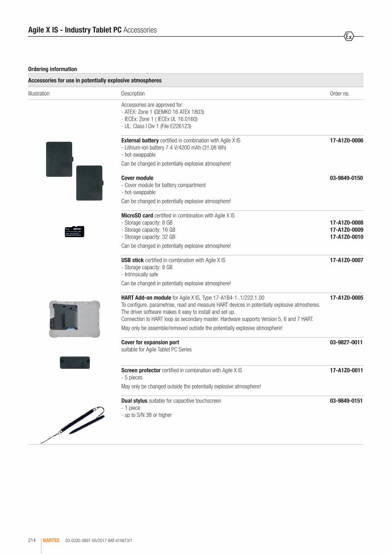
03-0330-0897-05/2017-BAT-410873/1BARTEC214
Bestellangaben
Zubehör für den Einsatz in explosionsgefährdeten Bereichen
Abbildung Beschreibung Bestellnummer
Das Zubehör ist zugelassen für: - ATEX: Zone 1 (DEMKO 16 ATEX 1803) - IECEx: Zone 1 (IECEx UL 16.0160) - UL: Class I Div 1 (File E226123)
Externer Akku zugelassen in Kombination mit dem Agile X IS - Lithium-Ionen-Akku 7,4 V/4200 mAh (31,08 Wh) - im Betrieb wechselbar
Darf in explosionsgefährdeten Bereichen gewechselt werden!
17-A1Z0-0006
Leermodul - Moduleinsatz für Akkufach - im Betrieb wechselbar
Darf in explosionsgefährdeten Bereichen gewechselt werden!
03-9849-0150
MicroSD-Karte zugelassen in Kombination mit dem Agile X IS - Speicherkapazität: 8 GB - Speicherkapazität: 16 GB - Speicherkapazität: 32 GB
Darf in explosionsgefährdeten Bereichen gewechselt werden!
17-A1Z0-0008 17-A1Z0-0009 17-A1Z0-0010
USB-Stick zugelassen in Kombination mit dem Agile X IS - Speicherkapazität: 8 GB - eigensicher
Darf in explosionsgefährdeten Bereichen gewechselt werden!
17-A1Z0-0007
HART Add-On-Modul für das Agile X IS, Typ 17-A1B4-1..1/222.1.00 Konfigurieren, Parametrieren, Auslesen und Messen von HART-Geräten im Ex-Bereich. Einfache Installation und Einrichtung durch verfügbare Treibersoftware. Anschluss an HART-Loop als sekundärer Master. Hardware unterstützt Version 5, 6 und 7 HART. Darf nur außerhalb von Ex-Bereich montiert/demontiert werden!
17-A1Z0-0005
Abdeckung für Erweiterungsschnittstelle geeignet für Tablet-PC Serie Agile
03-9827-0011
Displayschutzfolie zugelassen in Kombination mit dem Agile X IS - 5 Stück
Darf nur außerhalb von explosionsgefährdeten Bereichen gewechselt werden!
17-A1Z0-0011
Dual-Eingabestift geeignet für kapazitiven Touchscreen - 1 Stück - ab S/N 3B und höher
03-9849-0151
Agile X IS - Industry Tablet PC Accessories
Ordering information
Accessories for use in potentially explosive atmospheres
Illustration Description Order no.
Accessories are approved for: - ATEX: Zone 1 (DEMKO 16 ATEX 1803) - IECEx: Zone 1 ( IECEx UL 16.0160) - UL: Class I Div 1 (File E226123)
External battery certified in combination with Agile X IS - Lithium-ion battery 7.4 V/4200 mAh (31.08 Wh) - hot-swappable
Can be changed in potentially explosive atmosphere!
17-A1Z0-0006
Cover module - Cover module for battery compartment - hot-swappable
Can be changed in potentially explosive atmosphere!
03-9849-0150
MicroSD card certified in combination with Agile X IS - Storage capacity: 8 GB - Storage capacity: 16 GB - Storage capacity: 32 GB
Can be changed in potentially explosive atmosphere!
17-A1Z0-0008 17-A1Z0-0009 17-A1Z0-0010
USB stick certified in combination with Agile X IS - Storage capacity: 8 GB - Intrinsically safe
Can be changed in potentially explosive atmosphere!
17-A1Z0-0007
HART Add-on module for Agile X IS, Type 17-A1B4-1..1/222.1.00 To configure, parametrise, read and measure HART devices in potentially explosive atmosheres. The driver software makes it easy to install and set up. Connection to HART loop as secondary master. Hardware supports Version 5, 6 and 7 HART.
May only be assemble/removed outside the potentially explosive atmosphere!
17-A1Z0-0005
Cover for expansion port suitable for Agile Tablet PC Series
03-9827-0011
Screen protector certified in combination with Agile X IS - 5 pieces
May only be changed outside the potentially explosive atmosphere!
17-A1Z0-0011
Dual stylus suitable for capacitive touchscreen - 1 piece - up to S/N 3B or higher
03-9849-0151

03-0330-0897-05/2017-BAT-410873/2 BARTEC 215
Bestellangaben
Zubehör für den Einsatz in explosionsgefährdeten Bereichen
Abbildung Beschreibung Bestellnummer
Tragesystem geeignet für Agile X IS - vereinfacht das Handling - ergonomisches Rückentrapez mit Schulterpolster zum sicheren Tragen vor dem Körper - Zugriff auf Akku und Integration von Add-On Modulen möglich - mit Halterung für Eingabestift - verstellbare Gurtlänge
Lieferumfang - Leder-Schutztasche - 4-Punkt-Gurt - Schultergurt
03-9829-0101
Leder-Schutztasche geeignet für Agile X IS - mit praktischer Standfunktion und Halterung für Eingabestift - Zugriff auf Akku und Integration von Add-On Modulen möglich - erweiterbar um Schultergurt und 4-Punkt-Gurt - robustes Leder in Industriequalität
03-9829-0089
4-Punkt-Gurt geeignet für Leder-Schutztasche der Tablet-PC Serie Agile - ergonomisches Rückentrapez mit Schulterpolster zum sicheren Tragen vor dem Körper - einfache und sichere Montage an der Leder-Schutztasche durch farblich gekennzeichnete Druckknöpfe - verstellbare Gurtlänge
03-9829-0092
Schultergurt geeignet für Leder-Schutztaschen der Tablet-PC-Serie Agile - ergonomisches, weiches Schulterpolster - verstellbare Gurtlänge
03-9829-00912
Ordering information
Accessories for use in potentially explosive atmospheres
Illustration Description Order no.
Carry system suitable with Agile X IS - Simplified handling - Ergonomic back trace with shoulder pad for safe carrying in front of the body - Access to battery and integration of Add-on modules possible - with holder for stylus - adjustable strap length
Scope of delivery - Leather carry case - 4-point belt - Shoulder strap
03-9829-0101
Leather carry case suitable with Agile X IS - with practical stand function and holder for stylus - Access to battery and integration of Add-on modules possible - upgradable with shoulder strap and 4-point belt - robust industry quality leather
03-9829-0089
4-point belt suitable for leather protective case for the Agile Tablet PC Series - Ergonomic back trace with shoulder pad for safe carrying in front of the body - Easy and secure fitting on leather carry case using coloured pop fasteners - adjustable strap length
03-9829-0092
Shoulder strap suitable for leather carry case of tablet PC Agile series - ergonomic and soft shoulder pad - adjustable strap length
03-9829-0091
Agile X IS - Industry Tablet PC Accessories
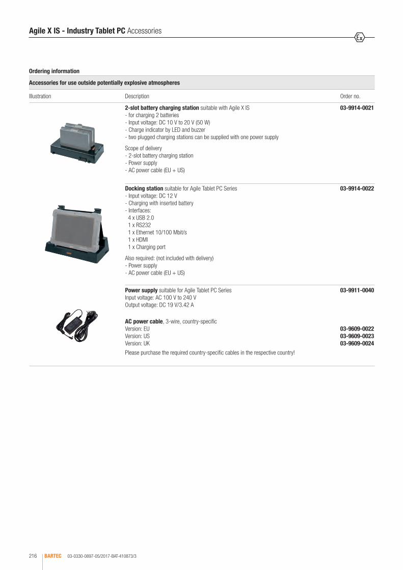
03-0330-0897-05/2017-BAT-410873/3BARTEC216
Bestellangaben
Zubehör für den Einsatz außerhalb von explosionsgefährdeten Bereichen
Abbildung Beschreibung Bestellnummer
2-fach-Akkuladestation geeignet für Agile X IS - zum Laden von zwei Akkus - Eingangsspannung: DC 10 V bis 20 V (50 W) - Ladeanzeige über LED und Summer - zwei zusammengesteckte Ladestationen können mit einem Netzteil versorgt werden
Lieferumfang - 2-fach-Akkuladestation - Netzteil - AC-Netzkabel (EU + US)
03-9914-0021
Docking-Station geeignet für Tablet-PC-Serie Agile - Eingangsspannung: DC 12 V - Laden mit eingesetztem Akku - Schnittstellen: 4 x USB 2.0 1 x RS232 1 x Ethernet 10/100 Mbit/s 1 x HDMI 1 x Ladeanschluss
Zusätzlich benötigt: (nicht im Lieferumfang enthalten) - Netzteil - AC-Netzkabel (EU + US)
03-9914-0022
Netzteil geeignet für Tablet-PC-Serie Agile Eingangsspannung: AC 100 bis 240 V Ausgangsspannung: DC 19 V/3,42 A
AC-Netzkabel, 3-adrig, länderspezifisch Version: EU Version: US Version: UK
Benötigte länderspezifische Kabel bitte im jeweiligen Land erwerben!
03-9911-0040
03-9609-0022 03-9609-0023 03-9609-0024
Agile X IS - Industry Tablet PC Accessories
Ordering information
Accessories for use outside potentially explosive atmospheres
Illustration Description Order no.
2-slot battery charging station suitable with Agile X IS - for charging 2 batteries - Input voltage: DC 10 V to 20 V (50 W) - Charge indicator by LED and buzzer - two plugged charging stations can be supplied with one power supply
Scope of delivery - 2-slot battery charging station - Power supply - AC power cable (EU + US)
03-9914-0021
Docking station suitable for Agile Tablet PC Series - Input voltage: DC 12 V - Charging with inserted battery - Interfaces: 4 x USB 2.0 1 x RS232 1 x Ethernet 10/100 Mbit/s 1 x HDMI 1 x Charging port
Also required: (not included with delivery) - Power supply - AC power cable (EU + US)
03-9914-0022
Power supply suitable for Agile Tablet PC Series Input voltage: AC 100 V to 240 V Output voltage: DC 19 V/3.42 A
AC power cable, 3-wire, country-specific Version: EU Version: US Version: UK
Please purchase the required country-specific cables in the respective country!
03-9911-0040
03-9609-0022 03-9609-0023 03-9609-0024

03-0330-0897-05/2017-BAT-410873/4 BARTEC 217
2
Agile X IS - Industry Tablet PC Service and Warranty
Ordering information
Service
Description Order no.
Service level COMFORT
Features: - Defined turnaround time - Product receipt/dispatch confirmation - Fast proposal management - Inspection fee included
Further details can be found in the contract documents.
3-year contract one-off payment 10 % of Agile X IS list price for the duration
4-year contract one-off payment 13.5 % of Agile X IS list price for the duration
5-year contract one-off payment 17 % of Agile X IS list price for the duration
Service level ALL-IN from the start
Features: - Defined turnaround time - Product receipt/dispatch confirmation - Projectable cost of ownership: repair cost included - Coverage of normal wear and tear and accidental damage - Repair working time and inspection fee included
Further details can be found in the contract documents.
3-year contract one-off payment 18 % of Agile X IS list price for the duration
4-year contract one-off payment 27 % of Agile X IS list price for the duration
5-year contract one-off payment 40 % of Agile X IS list price for the duration
00-1179
00-1189
00-1180
00-1181
00-1190
00-1182
Ordering information
Warranty
Description Order no.
Warranty extension (1-year contract) 5 % of Agile X IS list price for the duration
Warranty extension (2-year contract) 10 % of Agile X IS list price for the duration
Further details can be found in the contract documents.
00-1183
00-1184
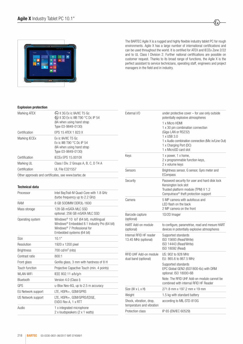
03-0330-0831-06/2017-BAT-374589/1BARTEC218
The BARTEC Agile X is a rugged and highly flexible industry tablet PC for rough environments. Agile X has a large number of international certifications and can be used throughout the world. It is certified for ATEX and IECEx Zone 2/22 and to UL Class I Division 2. Further national certifications are possible on customer request. Thanks to its broad range of functions, the Agile X is the perfect assistant to service technicians, operating staff, engineers and project managers in the field and in industry.
Agile X Industry Tablet PC 10.1"
Explosion protection
Marking ATEX II 3G Ex ic IIA/IIC T5 Gc II 3D Ex ic IIIB T90 °C Dc IP 54
(IIA when using hand strap Type 03-9849-0130)
Certification EPS 15 ATEX 1 823 X
Marking IECEx Ex ic IIA/IIC T5 Gc Ex ic IIIB T90 °C Dc IP 54 (IIA when using hand strap Type 03-9849-0130)
Certification IECEx EPS 15.0010X
Marking UL Class I Div. 2 Groups A, B, C, D T4 A
Certification UL File E321557
Other approvals and certificates, see www.bartec.de
Technical data
Processor Intel BayTrail-M Quad-Core with 1.8 GHz (turbo frequency up to 2.2 GHz)
RAM 8 GB SODIMM DDR3L-1600
Mass storage 128 GB mSATA MLC SSD optional: 256 GB mSATA MLC SSD
Operating system Windows® 10 IoT (64 bit), multilingual Windows® Embedded 8.1 Industry Pro (64 bit) Windows® 7 Professional for Embedded systems (64 bit)
Size 10.1"
Resolution 1920 x 1200 pixel
Brightness 700 cd/m² (nits)
Contrast ratio 800:1
Front glass Gorilla glass, 3 mm with hardness of 8 H
Touch function Projective Capactive Touch (min. 4 points)
WLAN-WiFi IEEE 802.11 a/b/g/n
Bluetooth Version 4.0 (Class I)
GPS u-Blox Neo-6Q, up to 2.5 m accuracy
EU Network support LTE, HSPA+, GSM/GPRS
US Network support LTE, HSPA+, GSM/GPRS/EDGE, EVDO Rev A, 1 x RTT
Audio 1 x integrated microphone 2 x loudspeakers (2 x 1 watts)
External I/O under protective cover – for use only outside potentially explosive atmospheres
1 x Micro HDMI 1 x 30 pin combination connection (Giga-LAN or RS232)1 x USB 3.0 1 x Audio combination connection (Mic in/Line Out) 1 x Charging Port (DC) 1 x MicroSD card slot
Keys 1 x power, 1 x home, 2 x programmable function keys, 2 x volume keys
Sensors Brightness sensor, G sensor, Gyro meter and ECompass
Security Password security for user and hard disk lock Kensington lock slot Trusted platform module (TPM) V 1.2 Computrace® theft protection support
Camera 5 MP camera with autofocus and LED flash on the back 2 MP camera on the front
Barcode capture (optional)
1D/2D Imager
HART Add-on module (optional)
to configure, parametrise, read and mesure HART devices in potentially explosive atmospheres
Internal RFID HF reader 13.45 MHz (optional)
Supported standards ISO 15693 (Read/Write) ISO 14443 (Read/Write) ISO 18092 (Read)
RFID UHF Add-on module dual band (optional)
US: 902 to 928 MHz EU: 865.6 to 867.5 MHz
Supported standards EPC Global GEN2 (ISO1800-6c) with DRM optional: ISO 18000-6B
Note: The RFID UHF Add-on module cannot be combined with internal RFID HF Reader
Size (W x L x H) 271.8 mm x 197.2 mm x 19 mm
Weight 1.5 kg with standard battery
Shock, vibration, drop, temperature and vibration
according to MIL-STD-810G
Protection class IP 65 (EN/IEC 60529)

03-0330-0831-06/2017-BAT-374589/2 BARTEC 219
2
Zubehör für den Einsatz in explosionsgefährdeten Bereichen
Accessories for use in potentially explosive atmospheres
Zubehör für den Einsatz außerhalb von explosionsgefährdeten Bereichen
Accessories for use outside potentially explosive atmospheres
Agile X Industry Tablet PC 10.1"
Operating temperature outside potentially explosive area -20 °C to +60 °C
inside potentially explosive area -20 °C to +50 °C
Storage temperature -30 °C to +70 °C
Operating humidity 30 % ~ 90 % (non-condensing)
Certification CE, FCC, UL 60950, ANSI/ISA 12.12.01, EN 60601
Power input DC 12 V to 19 V
Standard battery
Long life battery
Hot-Swap battery
Lithium-polymer battery 7.4 V/5300 mAh (39.22 Wh), charging time: 3 h, running time: up to 6 h
Lithium-polymer battery 7.4 V/10280 mAh (76.07 Wh), charging time: 6 h, running time: up to 13 h
7.4 V/330 mAh (integrated in the device)
Adapter AC 100 to 240 V, 50 to 60 Hz/DC 19 V
Warranty 3-years, can be extended by a further 1 or 2 years on request
Service contracts available for 3, 4 or 5 years COMFORT ALL-IN from the start
Scope of delivery Standard battery/optional Long life battery Stylus Hand strap Power supply Power cable (EU + US) Cover for interface extension Quick start guide
Optional accessories for use
in potentially explosive atmospheres: Standard battery/optional Long life battery Stylus Hand strap Screen protector Carry system Leather carry case 4-point belt Shoulder strap Radio module 4G/LTE (self-assembly) RFID UHF Add-on module (self-assembly) HART Add-on module (self-assembly)
outside potentially explosive atmospheres: 2-slot battery charging station Docking station Power supply Vehicle docking station Power supply with vehicle charge adapter Mounting plate for VESA mount LAN adapter cable/RS232 Micro HDMI cable
* cannot be combined with internal RFID HF ** cannot be combined with 1D/2D Imager
Complete order no. B7-A234-40 1/111 00 Please insert correct code. Technical data subject to change without notice.
Note: Optional modules such as LTE, RFID UHF, HART, etc. must be ordered separately as an accessory for self-assembly.
Ordering information
Operating system - 64 bit Code no. Battery Code no. RFID Code no. Barcode options Code no.
Windows® 7 Professional for embedded systems
1Standard battery 1 none 0 none 0
Windows® Embedded 8.1 Industry Pro
3
Long life battery 2 internal RFID HF Reader**
1 1D/2D Imager* 1Windows® 10 IoT 5

03-0330-0875-02/2017-BAT-392074/1BARTEC220
HART Add-on module for Agile X tablet PC
Explosion protection
Type 17-A1Z0-0005
Marking ATEX II 2G Ex ia [ia Ga] IIC T4 Gb
Certification EPS 15 ATEX 1 069 X
Marking IECEx Ex ia [ia Ga] IIC T4 Gb
Certification EPS 15.0065X
Marking NEC (USA/Canada)
Class I Div 1 Groups A, B, C, D T4
Certification CSA 70045374
Type G7-A0Z0-0007
Marking ATEX II (2)G [ia Ga] IIC
Certification EPS 15 ATEX 1 069 X
Marking IECEx [Ex ia] IIC Ga
Certification EPS 15.0065X
Kennzeichnung NEC Use with intrinsically safe outputs in non-potentially explosive atmospheres.
Type B7-A2Z0-0033
Marking ATEX II 3G Ex ic [ia Ga] IIC T4 Gc II 3D Ex ic [ia Da] IIIB T135 °C Dc
Certification EPS 15 ATEX 1 823 X
Marking IECEx Ex ic [ia Ga] IIC T4 Gc Ex ic [ia Da] IIIB T135 °C Dc
Certification EPS 15.0010X
Marking NEC (USA/Canada)
Class I Division 2 Groups A, B, C and D
Certification UL File E321557
Other country approvals on request.
Ordering information
HART Add-on module Order no.
for ATEX/IECEx Zone 1; Class I Div 1 17-A1Z0-0005
for non-Ex areas with intrinsically safe outputs G7-A0Z0-0007
for ATEX/IECEx Zone 2/22; Class I Div 2 B7-A2Z0-0033
Technical data subject to change without notice.
Technical data
Size (length x width x height)
125 mm x 125 mm x 24 mm
Weight 200 g
Protection class (IEC 60529)
mounted on tablet PC IP 54 connector strip (PoGo pins) IP 20
Operating temperature in the Ex area -20 °C to +50 °C in the safe area -20 °C to +60 °C
Storage temperature -30 °C to +70 °C
Air humidity during operation
30 % to 95 % (non-condensing)
HART interface UI ≤ DC 30 V II ≤ 130 mA PI ≤ 1 W UO ≤ DC 3 V IO ≤ 10 mA PO ≤ 5 mW Um ≤ DC 60 V max. cable length = 1.8 m
Energy management Power supply is via the extension interface of the tablet PC
Connection requirements HART loop connection The HART Add-on module may be connected to a non-certified HART device. Prerequisite: Um = 60 V or Ui is not exceeded!
HART interface Function as secondary master DTM communication driver supports FDT version 1.2.1 DTM communication driver supports network read/write/check/search (topology scan) Burst Mode is not supported by the communication driver HART-Protocol supports version 5, 6 and 7
Communication to the host (Agile X)
Via the extension interface of the tablet PC
DTM software Available DTM software supports the following 64-bit operating systems: Windows 7 Professional Windows 8.1 Embedded Industry Pro Windows 10 Enterprise
Service 1 year standard warranty Further 1 or 2 years on request
Scope of delivery HART Add-on module, screws, cable set, quick start guide
The HART Add-on module is a new extension module for Agile X and offers a HART modem function. It may be connected to a HART loop as secondary master and facilitates applications such as configuring the HART devices. Due to the Windows operating system, the user can deploy all current software solutions and communicate using the FDT/DTM industrial standard. Agile X equipped with HART Add-on module is the new safe solution when working in potentially explosive and non potentially explosive atmospheres: parameter assignment, configuration, measurement and office tasks can be carried out much easier, faster and more safely.

03-0330-0882-02/2017-BAT-402405/1 BARTEC 221
2
RFID UHF Add-on module for Agile X tablet PC
Explosion protection
Type B7-A2Z0-0033
The RFID UHF Add-on module is certified in combination with the Agile X, and can only be operated in combination with this in the potentially explosive atmosphere.
Marking ATEX II 3G Ex ic IIA/IIC T5 Gc II 3D Ex ic IIIB T90 °C Dc IP 54
(IIA when using hand strap Type 03-9849-0130)
Certification EPS 15 ATEX 1 823 X
Marking IECEx Ex ic IIA/IIC T5 Gc Ex ic IIIB T90 °C Dc IP 54 (IIA when using hand strap Type 03-9849-0130)
Certification EPS 15.0010X
Marking UL Class I Div. 2 Groups A, B, C, D T4 A
Certification UL File E321557
Other approvals and certificates, see www.bartec.de
Ordering information
RFID UHF Add-on module Order no.
for ATEX/IECEX Zone 2/22; Class I Div 2 B7-A2Z0-0032
Technical data subject to change without notice.
Technical data
Note: the device cannot be combined with the Agile X version with internal RFID HF reader.
Module used Thing Magic - Micro High Performance Multiprotocol embedded UHF RFID modules Type M6E-M
API suuport Thing Magic - Mercury-API Software Development Kit (SDK)
A development platform to connect, configure and control the RFID reader.
Development support Thing Magic - Universal Reader Assistant
This is a service program for the extended demonstration, testing and tuning of all Thing Magic RFID readers. It reduces the complexity for inexperienced users, while offering low level checking for advanced developers.
Frequency range Dual band
US: 902 to 928 MHz EU: 865.6 to 867.5 MHz
Frequency range can be adjusted in line with specific national specifications using the application development.
The intrinsically safe combination of the Agile X tablet PC system and the RFID UHF Add-on module enables the fast and efficient reading and writing of RFID transponders in a potentially explosive atmosphere in Zone 2/2 and Division 2. The modular system makes it possible to combine barcode and RFID recording in a single device. This means that users do not need to carry two separate devices with them. The data are available immediately for further processing and display on the tablet PC, and can be forwarded by means of radio tech-nology (Bluetooth, WiFi or LTE) in real time to other devices in the network. Applications to control the RFID reader can be programmed on the Windows based Agile X using the Mercury API from Thing Magic. The Mercury API Soft-ware Development Kit (SDK) contains numerous examples of applications and source codes for developers. It demonstrates and simplifies entry into the de-velopment and functionality of the RFID UHF reader. Further information on programming, the commands and the mode of operation can be found in the corresponding programming manual, the instructions for the SDK or on the Thing Magic website.
Weitere Zulassungen und Prüfbescheinigungen finden Sie unter www.bartec.de
Other approvals and certificates, see www.bartec.de
Autres agréments et certificats, voir www.bartec.de
Другие сертификаты и сертификаты, см. www.bartec.de
Consulte otras homologaciones y certificados de ensayo en www.bartec.de
Outras homologações e certificados de teste encontram-se em www.bartec.de
Diğer onay ve sertifikalar için bkz: www.bartec.de
Supported standards EPC Global GEN2 (ISO1800-6C) with DRM optional: IP-X and ISO 18000-6B
Nominal reading range up to approx. 150 cm
Nominal writing range up to approx. 150 cm
Antenna integrated antenna (50 Ω)
Maximum transmission power
The transmission power can be adjusted separately for reading and writing. Adjustable from 0 dBm to +30 dBm in 0.5 dBm steps Accuracy: +/- 1 dBm
Energy management power supply is via the extension interface of the tablet PC
Communication to the host (Agile X)
via the extension interface of the tablet PC
Operating system of the host (Agile X)
Windows® Embedded 8.1 Industry Pro (64 bit) Windows® 7 Professional SP1 for embedded systems (64 bit) Windows® 10 IoT (64 bit)
Size (L x W x H) 125 mm x 125 mm x 10 mm
Weight approx. 170 g
Protection class (IEC 60529)
mounted on tablet PC IP 54 connector strip (PoGo Pins) IP 20
Operating temperature inside potentially explosive areas -20 °C to +50 °C outside potentially explosive areas -20 °C to +60 °C
Storage temperature -30 °C to +70 °C
Operating humidity 30 % ~ 90 % (non-condensing)
Warranty 1 year, can be extended by a further 1 or 2 years on request
Scope of delivery RFID UHF Add-on module, fixing screws

03-0330-0881-06/2017-BAT-401143/1BARTEC222
Bestellangaben
Zubehör für den Einsatz in explosionsgefährdeten Bereichen
Abbildung Beschreibung Bestellnummer
Das Zubehör ist zugelassen für: - ATEX: Zone 2/22 (EPS 15 ATEX 1 823 X)- IECEx: Zone 2/22 (EPS 15.0010X)- UL: Div 2 (File E321557)
Standardakku - Lithium-Polymer-Akku 7,4 V/5300 mAh (39,22 Wh) - im Betrieb wechselbarDarf nur außerhalb von explosionsgefährdeten Bereichen gewechselt werden!
B7-A2Z0-0028
Langzeitakku - Lithium-Polymer-Akku 7,4 V/10280 mAh (76,07 Wh) - im Betrieb wechselbarDarf nur außerhalb von explosionsgefährdeten Bereichen gewechselt werden!
B7-A2Z0-0029
Akku-Verriegelung ermöglicht die Verriegelung des Akku, um versehentliches Entfernen zu verhindern
03-9827-0004
Abdeckung für Erweiterungsschnittstelle geeignet für Tablet-PC-Serie Agile XDarf nur außerhalb von explosionsgefährdeten Bereichen gewechselt werden!
03-9827-0011
HART Add-On Modul für Agile X, Typ B7-A234-4.../.... Konfigurieren, Parametrieren, Auslesen und Messen von HART-Geräten im Ex-Bereich. Einfache Installation und Einrichtung durch verfügbare Treibersoftware. Anschluss an HART Loop als sekundärer Master. Hardware unterstützt Version 5, 6 und 7 HART.Darf nur außerhalb von explosionsgefährdeten Bereichen montiert/demontiert werden!
B7-A2Z0-0033
RFID UHF Add-On Modul für Agile X, Typ B7-A234-4.../.... UHF RFID-Reader, Frequenz: Dual Band - EU: 865,6 bis 867,5 MHz - US: 902,0 bis 928,0 MHzDarf nur außerhalb von explosionsgefährdeten Bereichen montiert/demontiert werden!
B7-A2Z0-0032
Funkmodul 4G/LTE (US) kompatibel mit: Betriebssystem Windows Embedded 8.1 Industrie Pro Betriebssystem Windows 10 IoT Enterprise unterstützt: LTE, HSPA+ ,GSM/GPRS/EDGE, EV-DO Rev A, 1 x RTT
03-9826-0127
Funkmodul 4G/LTE (US) kompatibel mit: Betriebssystem Windows 7 Professional (für Embedded Systeme) unterstützt: LTE, HSPA+ ,GSM/GPRS/EDGE, EV-DO Rev A, 1 x RTT
03-9826-0142
Funkmodul 4G/LTE (EU) kompatibel mit: Betriebssystem Windows Embedded 8.1 Industrie Pro Betriebssystem Windows 10 IoT Enterprise unterstützt: LTE, HSPA+, GSM/GPRS
03-9826-0128
Funkmodul 4G/LTE (EU) kompatibel mit: Betriebssystem Windows 7 Professional (für Embedded Systeme) unterstützt: LTE, HSPA+, GSM/GPRS
03-9826-0141
Displayschutzfolie zugelassen in Kombination mit Agile X - 5 StückDarf nur außerhalb von explosionsgefährdeten Bereichen gewechselt werden!
B7-A2Z0-0031
Agile X - Industry Tablet PC Accessories
Ordering information
Accessories for use in potentially explosive atmospheres
Illustration Description Order no.
Accessories are approved for: - ATEX: Zone 2/22 (EPS 15 ATEX 1 823 X)- IECEx: Zone 2/22 (EPS 15.0010X)- UL: Div 2 (File E321557)
Standard battery - Lithium polymer battery 7.4 V/5300 mAh (39.22 Wh) - hot-swappableMay only be changed outside the potentially explosive atmosphere!
B7-A2Z0-0028
Long life battery - Lithium polymer battery 7.4 V/10280 mAh (76.07 Wh) - hot-swappableMay only be changed outside the potentially explosive atmosphere!
B7-A2Z0-0029
Battery lock Enables battery locking for prevent accidental removel
03-9827-0004
Cover for expansion port suitable for Agile Tablet PC Series XMay only be changed outside the potentially explosive atmosphere!
03-9827-0011
HART Add-on module for Agile X, type B7-A234-4.../.... To configure, parametrise, read and measure HART devices in potentially explosive atmospheres. The driver software makes it easy to install and set up. Connection to HART loop as secondary master. Hardware supports Version 5, 6 and 7 HART.
May only be assembled/removed outside the potentially explosive atmosphere!
B7-A2Z0-0033
RFID UHF Add-on module for Agile X, type B7-A234-4.../.... UHF RFID Reader, Frequency: Dual Band - EU: 865.6 up to 867.5 MHz - US: 902.0 up to 928.0 MHz May only be assembled/removed outside the potentially explosive atmosphere!
B7-A2Z0-0032
Radio module 4G/LTE (US) compatible with: Operating system Windows Embedded 8.1 Industry pro Operating system Windows 10 IoT Enterprise support: LTE, HSPA+ ,GSM/GPRS/EDGE, EV-DO Rev A, 1 x RTT
03-9826-0127
Radio module 4G/LTE (US) compatible with: Operating system Windows 7 Professional (for embedded systems) support: LTE, HSPA+ ,GSM/GPRS/EDGE, EV-DO Rev A, 1 x RTT
03-9826-0142
Radio module 4G/LTE (EU) compatible with: Operating system Windows Embedded 8.1 Industry pro Operating system Windows 10 IoT Enterprise support: LTE, HSPA+, GSM/GPRS
03-9826-0128
Radio module 4G/LTE (EU) compatible with: Operating system Windows 7 Professional (for embedded systems) support: LTE, HSPA+, GSM/GPRS
03-9826-0141
Screen protector certified in combination with Agile X - 5 pieces
May only be changed outside the potentially explosive atmosphere!
B7-A2Z0-0031

03-0330-0881-06/2017-BAT-401143/2 BARTEC 223
Bestellangaben
Zubehör für den Einsatz in explosionsgefährdeten Bereichen
Abbildung Beschreibung Bestellnummer
Dual-Eingabestift geeignet für kapazitiven Touchscreen - 1 Stück - mit Spiralkabel - ab S/N 3B und höher
03-9849-0151
Eingabestift geeignet für Agile und Agile X - 1 Stück - mit Gummispitze
03-9849-0131
Gummispitze für Eingabestift geeignet für Eingabestift, Typ 03-9849-0131 - 1 Stück
03-9849-0140
Tragesystem geeignet für Agile und Agile X - vereinfacht das Handling - ergonomisches Rückentrapez mit Schulterpolster zum sicheren Tragen vor dem Körper - Zugriff auf Akku und Integration von Add-On-Modul möglich - mit Halterung für Eingabestift - verstellbare Gurtlänge
Lieferumfang - Leder-Schutztasche - 4-Punkt-Gurt - Schultergurt
03-9829-0100
Leder-Schutztasche geeignet für Agile und Agile X - mit praktischer Standfunktion und Halterung für Eingabestift - Zugriff auf Akku und Integration von Add-On-Modul möglich - erweiterbar um Schultergurt und 4-Punkt-Gurt - robustes Leder in Industriequalität
03-9829-0090
4-Punkt-Gurt geeignet für Leder-Schutztaschen der Tablet-PC-Serie Agile - ergonomisches Rückentrapez mit Schulterpolster zum sicheren Tragen vor dem Körper - einfache und sichere Montage an der Leder-Schutztasche durch farblich gekennzeichnete Druckknöpfe - verstellbare Gurtlänge
03-9829-0092
Schultergurt geeignet für Leder-Schutztaschen der Tablet-PC-Serie Agile - ergonomisches, weiches Schulterpolster - verstellbare Gurtlänge
03-9829-0091
Schultergurt geeignet für Agile und Agile X - ermöglicht ergonomisches Tragen - Schultergurt mit Polster - verstellbare Gurtlänge
03-9849-0132
Handgurt geeignet für Agile und Agile X - 1 Stück - zur Montage auf der Rückseite
03-9849-0130
2
Agile X - Industry Tablet PC Accessories
Ordering information
Accessories for use in potentially explosive atmospheres
Illustration Description Order no.
Dual stylus suitable for capacitive touchscreen - 1 piece - with spiral cord - as from S/N 3B or higher
03-9849-0151
Stylus suitable with Agile and Agile X - 1 piece - with rubber tip
03-9849-0131
Rubber tip for stylus suitable for stylus, type 03-9849-0131 - 1 piece
03-9849-0140
Carry system suitable with Agile and Agile X - Simplifies handling - Ergonomic back trace with shoulder pad for safe carrying in front of the body - Access to battery and integration of Add-on modules possible - with holder for stylus - adjustable strap length
Scope of delivery - Leather carry case - 4-point belt - Shoulder strap
03-9829-0100
Leather carry case suitable with Agile and Agile X - with practical stand function and holder for stylus - Access to battery and integration of Add-on modules possible - upgradable with shoulder strap and 4-point belt - robust industry quality leather
03-9829-0090
4-point belt suitable for leather carry case of Agile Tablet PC Series - Ergonomic back trace with shoulder pad for safe carrying in front of the body - Easy and secure fitting on leather carry case using coloured pop fasteners - adjustable strap length
03-9829-0092
Shoulder strap suitable for leather carry case of Agile Tablet PC Series - ergonomic and soft shoulder pad - adjustable strap length
03-9829-0091
Shoulder strap suitable for Agile and Agile X - allows ergonomic carrying - shoulder strap with pad - adjustable strap length
03-9849-0132
Hand strap suitable for Agile and Agile X - 1 piece - to be mounted on the back
03-9849-0130

03-0330-0881-06/2017-BAT-401143/3BARTEC224
Bestellangaben
Zubehör für den Einsatz außerhalb von explosionsgefährdeten Bereichen
Abbildung Beschreibung Bestellnummer
2-fach-Akkuladestation geeignet für Agile und Agile X - zum Laden von zwei Akkus - Eingangsspannung: DC 10 V bis 20 V (50 W) - Ladeanzeige über LED und Summer - zwei zusammengesteckte Ladestationen können mit einem Netzteil versorgt werden
Lieferumfang - 2-fach-Akkuladestation - Netzteil - AC-Netzkabel (EU + US)
03-9914-0010
Docking-Station geeignet für Agile und Agile X - Eingangsspannung: DC 9 V bis 36 V - Laden mit eingesetztem Akku - Schnittstellen: 4 x USB 2.0 1 x RS232 1 x Ethernet 10/100 Mbit/s 1 x VGA 1 x Ladeanschluss
Zusätzlich benötigt: (nicht im Lieferumfang enthalten) - Netzteil - AC-Netzkabel (EU + US)
Docking-Station geeignet für Tablet-PC-Serie Agile - Eingangsspannung: DC 12 V - Laden mit eingesetztem Akku - Schnittstellen: 4 x USB 2.0 1 x RS232 1 x Ethernet 10/100 Mbit/s 1 x HDMI 1 x Ladeanschluss
Zusätzlich benötigt: (nicht im Lieferumfang enthalten) - Netzteil - AC-Netzkabel (EU + US)
03-9915-0017
Netzteil geeignet für Tablet-PC-Serie Agile Eingangsspannung: AC 100 bis 240 V Ausgangsspannung: DC 19 V/3,42 A
AC-Netzkabel, 3-adrig, länderspezifisch Version: EU Version: US Version: UK
Benötigte länderspezifische Kabel bitte im jeweiligen Land erwerben!
03-9911-0040
03-9609-0022 03-9609-0023 03-9609-0024
Ordering information
Accessories for use outside potentially explosive atmospheres
Illustration Description Order no.
2-slot battery charging station suitable with Agile and Agile X - for charging 2 batteries - Input voltage: DC 10 V to 20 V (50 W) - Charge indicator by LED and buzzer - two plugged charging stations can be supplied with one power supply
Scope of delivery - 2-slot battery charging station - Power supply - AC power cable (EU + US)
03-9914-0010
Docking station suitable for Agile and Agile X - Input voltage: DC 9 V to 36 V - Charging with inserted battery - Interfaces: 4 x USB 2.0 1 x RS232 1 x Ethernet 10/100 Mbit/s 1 x VGA 1 x Charging port
Also required: (not included with delivery) - Power supply - AC power cable (EU + US)
Docking station suitable for Agile Tablet PC Series - Input voltage: DC 12 V - Charging with inserted battery- Interfaces: 4 x USB 2.0 1 x RS232 1 x Ethernet 10/100 Mbit/s 1 x HDMI 1 x Charging port
Also required: (not included with delivery) - Power supply - AC power cable (EU + US)
03-9915-0017
03-9914-0022
Power supply suitable for Agile Tablet PC Series Input voltage: AC 100 V to 240 V Output voltage: DC 19 V/3.42 A
AC power cable, 3-wire, country-specific Version: EU Version: US Version: UK
Please purchase the required country-specific cables in the respective country!
03-9911-0040
03-9609-0022 03-9609-0023 03-9609-0024
Agile X - Industry Tablet PC Accessories

03-0330-0881-06/2017-BAT-401143/4 BARTEC 225
Bestellangaben
Zubehör für den Einsatz außerhalb von explosionsgefährdeten Bereichen
Abbildung Beschreibung Bestellnummer
Fahrzeug-Docking-Station geeignet für Agile und Agile X - Eingangsspannung: DC 9 V bis 36 V - Laden mit eingesetztem Akku - mit Verriegelung - Schnittstellen: 2 x USB 2.0 1 x RS232 1 x Ethernet 10/100 Mbit/s 1 x VGA 1 x SMA für externe GPS-Antenne 1 x Ladeanschluss 1 x Klemmleiste für Spannungsversorgung
Zusätzlich benötigt: (nicht im Lieferumfang enthalten) - Netzteil mit Fahrzeug-Ladeadapter - Abdeckung für Erweiterungsschnittstelle
Hinweis: Abdeckung der Erweiterungsschnittstelle muss gewechselt werden.
03-9915-0018
Netzteil mit Fahrzeug-Ladeadapter Eingangsspannung: DC 11 V bis 16 V und DC 22 V bis 24 V Ausgangsspannung: DC 19 V/3,42 A
03-9914-0011
Abdeckung für Erweiterungsschnittstelle geeignet für Agile und Agile X - für Fahrzeug-Docking-Station
03-9827-0005
Montageplatte für VESA-Halterung geeignet für Agile und Agile X - Material: Metall
03-9849-0133
Adapterkabel LAN für LAN mit 30-Pin Erweiterungsport - Buchse: RJ45
03-9919-0022
Adapterkabel RS232 für RS232 mit 30-Pin Erweiterungsport - Stecker: DB9 Serial RS232
03-9919-0023
Micro HDMI-Kabel - Micro HDMI (Stecker) auf HDMI (Stecker)
03-9919-0024
2
Ordering information
Accessories for use outside potentially explosive atmospheres
Illustration Description Order no.
Vehicle docking station suitable for Agile and Agile X - Input voltage: DC 9 V to 36 V - Charging with inserted battery - with locking function - Interfaces: 2 x USB 2.0 1 x RS232 1 x Ethernet 10/100 Mbit/s 1 x VGA 1 x SMA for external GPS antenna 1 x Charging port 1 x Terminal block for power supply
Also required: (not included with delivery) - Power supply with vehicle charging adapter - Cover for expansion portNote: Cover of the expansion port must be changed.
03-9915-0018
Power supply with vehicle charging adapter Input voltage: DC 11 V to 16 V and DC 22 V to 24 V Output voltage: DC 19 V/3.42 A
03-9914-0011
Cover for expansion port suitable for Agile and Agile X - for vehicle docking station
03-9827-0005
Mounting plate for VESA mount suitable for Agile and Agile X - Material: metal
03-9849-0133
LAN adapter cable for LAN from 30 pin extension port - Connector: RJ45, female
03-9919-0022
RS232 adapter cable with 30 pin extension port - Connector: DB9 Serial RS232 cable (Male)
03-9919-0023
Micro HDMI cable - Micro HDMI (Male) to HDMI (Male)
03-9919-0024
Agile X - Industry Tablet PC Accessories

03-0330-0881-06/2017-BAT-401143/5BARTEC226
Agile X - Industry Tablet PC Service and warranty
Ordering information
Service
Description Order no.
Service Level COMFORT
Features:- Defined turnaround time - Product receipt/dispatch confirmation - Fast proposal management - Inspection fee included
Further details can be found in the contract documents.
3-year contract one-off payment 10 % of Agile X list price for the duration
4-year contract one-off payment 13.5 % of Agile X list price for the duration
5-year contract one-off payment 17 % of Agile X list price for the duration
Service level ALL-IN from the start
Features: - Defined turnaround time - Product receipt/dispatch confirmation - Projectable cost of ownership: repair cost included - Coverage of normal wear and tear and accidental damage - Repair working time and inspection fee included
Further details can be found in the contract documents.
3-year contract one-off payment 18 % of Agile X list price for the duration
4-year contract one-off payment 27 % of Agile X list price for the duration
5-year contract one-off payment 40 % of Agile X list price for the duration
00-1179
00-1189
00-1180
00-1181
00-1190
00-1182
Ordering information
Warranty
Description Order no.
Warranty extension (1-year contract) 5 % of Agile X list price for the duration
Warranty extension (2-year contract) 5 % of Agile X list price for the durationFurther details can be found in the contract documents.
00-1183
00-1184

03-0330-0866-06/2017-BAT-391253/1 BARTEC 227
2
Lumen X7 from BARTEC is a rugged and highly flexible industrial tablet for rough environments. Lumen X7 has a large number of international certifi-cations and can be used throughout the world. It is approved for ATEX and IECEx Zone 2/22 and for UL Class I Division 2. Approvals for other countries are possible on customer request. Thanks to its numerous functions, the Lumen X7 provides perfect support for warehouse management, transport, service technicians, operating personnel, engineers and project managers in the field and in industry.
Lumen X7 Industry Tablet
Explosion protection
Marking ATEX II 3G Ex ic IIC T5 Gc II 3D Ex ic IIIB T100 °C Dc
Certification EPS 15 ATEX 1 037 X
Marking IECEx Ex ic IIC T5 Gc Ex ic IIIB T100 °C Dc
Certification IECEx EPS 15.0053X
Marking UL Class I Div. 2 Groups A, B, C and D T6
Certification UL File E321557
Other approvals and certificates, see www.bartec.de
Technical data
Protection class (EN/IEC 60529)
IP 54 (Non-Ex IP 65)
Operating temperature -10 °C to +50 °C
Storage temperature -30 °C to +60 °C
Air humidity during operation
5 % to 95 % (non-condensing)
Processor ARM® Cortex™-A7 Quad Core 1.5 GHz
Mass storage 1 GB Mobile DDR2
RAM 16 GB eMMC
Expandable memory MicroSD card up to 32 GB supported
Operating system Android 4.2.1 (Jelly Bean)
Size 7" WSVGA TFT LCD display
Resolution 1024 x 600 pixels
Brightness 500 cd/m² (nits)
Touch function Projective capacitive multi-touch
Wireless communication
WLAN IEEE 802.11 a/b/g/nBluetooth Version 3.0 + EDRGPS integratedWWAN 3.75G-GSM/GPRS/EDGE/WCDMA/ HSDPA/HSUPA Includes telephone function Exception: data transmission only within the EU
Audio 1 x loudspeaker (1 x 1.2 watts) 1 x audio combination connection (Microphone In/Line Out)
External I/0 only for use outside potentially explosive areas 1 x Micro USB 2.0 Type B (OTG) 1 x MicroSD card slot 1 x Micro SIM card slot 1 x Port for docking station 1 x Charging port (DC)
Keys 1 x Power on/off button 2 x volume buttons (+/-) 4 x function buttons (home, F1, F2, menu)
LED 1 x LED indicator (battery and status of power mode)
Camera 5 MP camera with autofocus and LED flash on the back
Size (L x W x H) 212.4 mm x 132.8 mm x 19 mm
Weight approx. 600 g with battery
03-0330-0866-06/2017-BAT-391253/2BARTEC228
Lumen X7 Industry Tablet
RFID HF/NFC - 13.45 MHz supported standards (Near Field Communication) Integrated read/write, peer to peer mode
ISO 15693 (Read) TI HF-I Plus, TI HF-I Pro, NXPI-Code SLI
ISO 14443-A (Read) NXP Mifare_One (S50_4byte), NXP Mifare_One (S50_7byte), NXP Mifare_One (S70_4byte), NXP Mifare_UltraLight, NXP Mifare_UltraLight C, NXP Mifare DesFire_EVI
ISO 18092 (Read/Write) SONY Felica Lite SONY Felica Lite s
Ordering information
Description Order no.
Lumen X7 without 1D/2D Imager, without 3.75G
B7-A234-2043/44330000
Lumen X7 without 1D/2D Imager, with 3.75G
B7-A234-2343/44330000
Technical data subject to change without notice.
Battery Lithium-polymer battery 3.7 V/5300 mAh, Battery life up to 20 hrs., Charge time using power supply with plug-in adapter: up to 3.5 hrs, can be replaced outside potentially explosive atmospheres
Power supply with plug-in adapter (EU + US)
Input: AC 100 to 240 V/50 to 60 Hz/0.6 A Output: DC 5 V/3 A/15 W max.
Warranty 3 years
Service agreements available on request
Scope of delivery Lumen X7 Battery Hand strap Stylus Power supply Plug-in adapter (EU + US) Quick start guide (DE + EN)
Optional accessories for use
in potentially explosive atmospheres: Battery Hand strap Stylus Screen protector MicroSD card
outside potentially explosive atmospheres: Docking Station Power supply with plug-in adapter (EU + US) Vehicle docking station Power supply with vehicle charging adapter

03-0330-0879-06/2017-BAT-401139/1 BARTEC 229
Bestellangaben
Zubehör für den Einsatz in explosionsgefährdeten Bereichen
Abbildung Beschreibung Bestellnummer
Das Zubehör ist zugelassen für: - ATEX Zone 2/22 (EPS 15 ATEX 1 037 X) - IECEx Zone 2/22 (EPS 15.0053 X) - UL Class I Div 2 (File E321557)
Akku - Lithium-Polymer-Akku 3,7 V/5300 mAh (19,61 Wh)
Darf nur außerhalb von explosionsgefährdeten Bereichen gewechselt werden!
B7-A2Z0-0027
Displayschutzfolie zugelassen in Kombination mit Lumen X-Serie - 5 Stück
Darf nur außerhalb von explosionsgefährdeten Bereichen gewechselt werden!
B7-A2Z0-0030
Speicherkartenerweiterung für Lumen X-Serie - basierend auf der Industrieausführung von ATP - zugelassen in Kombination mit der Lumen X-Serie - kann nur außerhalb von explosionsgefährdeten Bereichen gewechselt werden
MicroSD-Karten sind nicht im Zertifikat festgeschrieben. Kunde kann MicroSD-Karte frei auswählen.
BARTEC empfiehlt die Verwendung folgender MicroSD-Karten: - MicroSD-Karte mit 4 GB - MicroSD-Karte mit 8 GB
17-28BE-F006/000A 17-28BE-F006/000B
Handgurt zugelassen in Kombination mit Lumen X7 - 1 Stück - zur Montage auf der Rückseite
03-9849-0141
Eingabestift zugelassen in Kombination mit Lumen X7 - 1 Stück
03-9849-0144
2
Industry Tablet Lumen X7 Accessories
Ordering information
Accessories for use in potentially explosive atmospheres
Illustration Description Order no.
Accessories are approved for: - ATEX Zone 2/22 (EPS 15 ATEX 1 037 X) - IECEx Zone 2/22 (EPS 15.0053 X) - UL Class I Div. 2 (File E321557)
Battery - Lithium-polymer battery 3.7 V/5300 mAh (19.61 Wh)
May only be changed outside the potentially explosive atmosphere!
B7-A2Z0-0027
Screen protector certified in combination with Lumen X7 - 5 pieces
May only be changed outside the potentially explosive atmosphere!
B7-A2Z0-0030
Expanded memory for Lumen X series - based on Industry version of ATP - certified in combination with Lumen X series - can only be replaced outside potentially explosive atmosphere
MicroSD cards are not specified in certificate. The customer can use anyMicroSD card.
BARTEC recommends the use of following MicroSD cards: - MicroSD card with 4 GB - MicroSD card with 8 GB
17-28BE-F006/000A 17-28BE-F006/000B
Hand strap certified in combination with Lumen X7 - 1 piece - to be mounted on the back
03-9849-0141
Stylus certified in combination with Lumen X7 - 1 piece
03-9849-0144
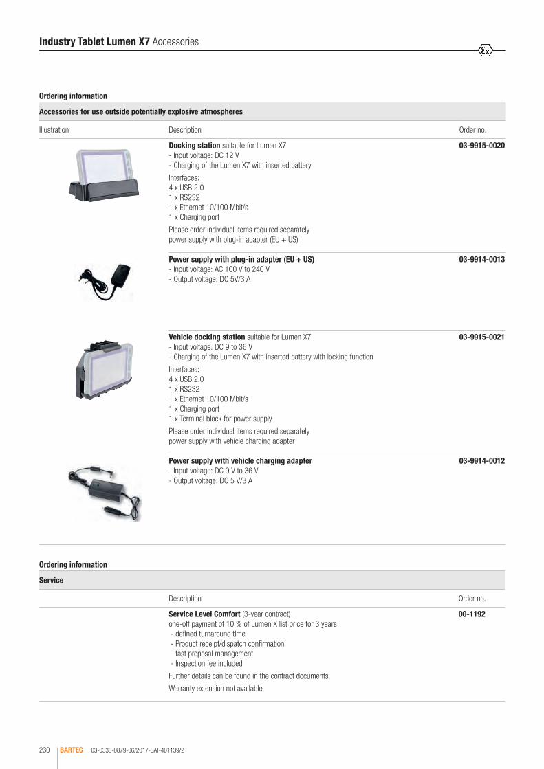
03-0330-0879-06/2017-BAT-401139/2BARTEC230
Bestellangaben
Zubehör für den Einsatz außerhalb von explosionsgefährdeten Bereichen
Abbildung Beschreibung Bestellnummer
Docking-Station geeignet für Lumen X7 - Eingangsspannung: DC 12 V - Laden des Lumen X7 mit eingesetztem Akku
Schnittstellen: 4 x USB 2.0 1 x RS232 1 x Ethernet 10/100 Mbit/s 1 x Ladeanschluss
Benötigte Einzelteile bitte separat bestellen: Netzteil mit Steckeradapter (EU + US)
03-9915-0020
Netzteil mit Steckeradapter (EU + US) - Eingangsspannung: AC 100 V bis 240 V - Ausgangsspannung: DC 5V/3 A
03-9914-0013
Fahrzeug-Docking-Station geeignet für Lumen X7 - Eingangsspannung: DC 9 bis 36 V - Laden des Lumen X7 mit eingesetztem Akku, mit Verriegelung
Schnittstellen: 4 x USB 2.0 1 x RS232 1 x Ethernet 10/100 Mbit/s 1 x Ladeanschluss 1 x Klemmleiste für Spannungsversorgung
Benötigte Einzelteile bitte separat bestellen: Netzteil mit Fahrzeug-Ladeadapter
03-9915-0021
Netzteil mit Fahrzeug-Ladeadapter - Eingangsspannung: DC 9 V bis 36 V - Ausgangsspannung: DC 5 V/3 A
03-9914-0012
Ordering information
Service
Description Order no.
Service Level Comfort (3-year contract) one-off payment of 10 % of Lumen X list price for 3 years - defined turnaround time - Product receipt/dispatch confirmation - fast proposal management - Inspection fee included
Further details can be found in the contract documents.
Warranty extension not available
00-1192
Industry Tablet Lumen X7 Accessories
Ordering information
Accessories for use outside potentially explosive atmospheres
Illustration Description Order no.
Docking station suitable for Lumen X7 - Input voltage: DC 12 V - Charging of the Lumen X7 with inserted battery
Interfaces: 4 x USB 2.0 1 x RS232 1 x Ethernet 10/100 Mbit/s 1 x Charging port
Please order individual items required separately power supply with plug-in adapter (EU + US)
03-9915-0020
Power supply with plug-in adapter (EU + US) - Input voltage: AC 100 V to 240 V - Output voltage: DC 5V/3 A
03-9914-0013
Vehicle docking station suitable for Lumen X7 - Input voltage: DC 9 to 36 V - Charging of the Lumen X7 with inserted battery with locking function
Interfaces: 4 x USB 2.0 1 x RS232 1 x Ethernet 10/100 Mbit/s 1 x Charging port 1 x Terminal block for power supply
Please order individual items required separately power supply with vehicle charging adapter
03-9915-0021
Power supply with vehicle charging adapter - Input voltage: DC 9 V to 36 V - Output voltage: DC 5 V/3 A
03-9914-0012

MOBILE CAMERA SYSTEMS/SMARTPHONES


CONTENT
Gravity X Intrinsically Safe Camera 17-K113-1012111.0000
234 - 235
Accessories Gravity X 00-..; 03-..
236 - 237
Orbit X Explosion-proof Wi-Fi Camera 17-K123-1012111.0000
238 - 239
Accessories Orbit X 03-..
240
Impact X Intrinsically Safe Smartphone 17-S123-1112111.0000
241 - 242
Accessories Impact X 00-..; 03-..
243 - 244
Mobile X Industrial Mobile Phone for Zone 1/21 and Div 1 17-S113-1.00
245
Accessories Mobile X 03-..
246 - 247

03-0330-0924-10/2017-BAT-414828/1BARTEC234
Full HD 1080 p video and 8 Mpix imaging, high-end lenses, ultra-fast zoom and autofocus make the Gravity X an extremely powerful piece of equip-ment. It can take photos and make audio and video recordings in potentially explosive atmospheres, and immediately load and save them to a network or a computer. The camera has high battery capacity, fast autofocus lens and high-resolution image sensors. The extremely light-sensitive image sen-sor and powerful LED lamps guarantee outstanding images and recordings. The Gravity X also comes with FlipScapeTM, a novel application which always records videos correctly, irrespective of which way the camera is held. This is because the Gravity X automatically switches to a second camera that is at a 90° angle to the standard camera. This means you can record in landscape mode using one hand, leaving the other hand free. A special camera button provides the basis for professional images. This camera button works in two steps. Before taking the photo, you can first adjust the AE parameters in the same way as with your digital single-lens reflex camera. The Gravity X comes with various camera apps, which enable you to adapt the camera to your requirements and which broaden potential uses.
Gravity X Intrinsically Safe Camera
Explosion protection
Marking ATEX
Certification
II 2G Ex ib op is IIC T4 Gb
Sira 14ATEX2287X
Marking IECEx Ex ib op is IIC T4 Gb
Certification SIR 14.0105 X
Marking CSA Class I, Ex ib IIC T4 Gb Class I, AEx ib IIC T4 Gb
Certification CSA file: 70056527
Other approvals and certificates, see www.bartec.de
Technical data
Temperature range
Operating temperature -20 °C to +45 °C
Storage temperature -40 °C to +60 °C
Video and imaging
Video quality Full HD video (1080 p, 30 fps)
Resolution 8 megapixel stills
Image capture Dedicated camera button
Video codecs H.264/AVC codec
Zoom 4 x
Memory 16 to 32 GB
Robust design
Impact Impact-resistant to 2 joules
Drop Drop-resistant to 2 metres
Submersible Waterproof (IP 68)
Enclosure Made from one piece of aluminium
Connections Covered USB
Screen 2 mm Gorilla Glass
Audio
Microphone Digital omnidirectional microphone
Audio Full duplex audio communication
Video recording Stereo microphones on back
Wireless headset Bluetooth audio headset support
Handsfree Integrated mic and speaker
Audio codec CD quality AAC LD
Audio out Standard 3.5 mm connection
Sensors
Orientation 3 axis gyroscope
Positioning Global Positioning System (GPS)
Acceleration Accellerometer
Navigation Compass
Power input
Battery size 3000 mAh
Video playback 8 h
Video recording 4 to 6 h full operating time
Scope of delivery
Charger USB
Image transfer Standard software for transfering images
Warranty 1 year hardware warranty
User Manual Quick guide
Packaging With customised foam inlays
Size and weight
Size 150 mm x 65 mm x 12 mm
Weight 290 g (10 oz)

03-0330-0924-10/2017-BAT-414828/2 BARTEC 235
2
Gravity X Intrinsically Safe Camera
Display and touchscreen
Screen size 4.3 inch Retina display
Resolution 480 x 800 pixels
Brightness Display can be read in direct sunlight
Touchscreen Suitable for use when wearing gloves
Glass Gorilla glass (IP 68)
Buttons On/Off, Volume, Camera, Android
Applications
HD Video conference SIPIDO
Management Solution Collaboration Suite
Browser HTML5 with full range of features
Document display PDF and Office documents
ERP Compatible with ERP systems
Apps Over 1.3 million on Google Play
Ergonomics
Image capture Flipscape™: take videos using one hand
Dirt protection Anti-smuge recess for camera glass and screen
Touchscreen Suitable for use when wearing gloves, moisture resistant
Shape factor Fits in hand and pocket
Fall protection Strap for ergonomic operation
Network functions
Wi-Fi 802.11 a/b/g/n (2.4 GHz & 5 GHz)
Bluetooth Bluetooth 4.0
Wi-Fi media sharing Dropbox™, Picasa™, Flickr™, Box™, Oned-rive™
Operating system
Android 5.1.1 Lollipop
Ordering information
Gravity X for Europe 17-K113-101211110000
Gravity X for US 17-K113-101211120000
Gravity X for Australia 17-K113-101211130000
Gravity X for UK 17-K113-101211140000
Technical data subject to change with notice.

03-0330-0925-10/2017-BAT-414829/1BARTEC236
Gravity X Accessories
Ordering information
Illustration Description Order no.
Strap for hand and belt (multifunctional)
03-9829-0081
Hand strap (with snap hook)
03-9829-0082
Shoulder strap (with snap hook)
03-9829-0084
Bluetooth headset- with neck neckband- with head band - for mounting on a helmet
03-9810-0203 03-9810-0204 03-9810-0205
Telescopic pole 03-9829-0086
Protective cover black orange
03-9869-0021 03-9869-0022
Tripod mount 03-9829-0085

03-0330-0925-10/2017-BAT-414829/2 BARTEC 237
2
Gravity X Accessories
Ordering information
Illustration Description Order no.
Charger USB charger and USB cable - Input voltage: AC 100 to 240 V - Output: USB
Version for - Europe - US - Australia - UK
03-9810-0199 03-9810-0184 03-9810-0186 03-9810-0185
Micro USB cable 60 cm 03-9828-0055
Ordering information
Service
Description Order no.
BASIC Service Level Response within 72 hours Repair within 14 days OTA firmware updates sent free of charge
SILVER Service Level Response within 48 hours Repair within 7 days OTA firmware updates sent free of charge
GOLD Service Level Response within 24 hours Repair within 2 days OTA firmware updates sent free of charge Includes advice: 1 hour per month
00-1202
00-1201
00-1200

03-0330-0923-10/2017-BAT-414827/1BARTEC238
Orbit X is the toughest, most intelligent and smallest explosion-protected camera. It has an HD image sensor, two LED lamps and a laser pointer. This means in potentially explosive atmospheres it is also possible to take pho-tos and record videos, hold live wireless video conferences and use video streaming for monitoring. Using 1080p Wi-Fi, the camera with its compact and robust design can record, stream and display videos and 8 megapixel stills. Images and videos recorded in the field can then be transmitted via USB to any computer. Orbit X offers the option of remote management using the Collaboration X Device Management System. The camera can be connected by Wi-Fi to any Android device. The SIPIDO app is also included by way of standard, permitting video conferencing by Wi-Fi in full HD.
Orbit X Explosion-proof Wi-Fi Camera
Explosion protection
Marking ATEX
Certification
II 2G Ex ib op is IIC T4 Gb
Sira 13ATEX5134X
Marking IECEx Ex ib op is IIC T4 Gb
Certification SIR 13.0047X
Marking CSA Class I, Ex ib op is IIC T4 Gb Class I, AEx ib op is IIC T4 Gb
Certification CSA file: 70009910
Other approvals and certificates, see www.bartec.de
Technical data
Protection class IP 68 water proof
Shock resistance Shock-resistant to 4 Joules/ Drop-resistant to 2 metres
Wireless CE and FCC compliant
Temperature range
Operating temperature -20 °C bis +45 °C
Storage temperature -40 °C bis +60 °C
Video and imaging
Video resolution Full HD video (1080p, 30 fps (frames per second))
Image resolution 8 megapixel stills
Buttons Power/standby, light/laser and video/photo/call
Codecs H.264/AVC
Memory 16 to 32 GB of internal video and image storage
Image sensor 1/3 inch high-end CMOS sensor (8 Mpix)
Light modes Powerful video LED light
Dimensions and weight
Length 117.5 mm
Diameter 27 mm
Weight 105 g
Storage temperature -40 °C to +60 °C
Operating temperature -20 °C to +45 °C
Camera glass Gorilla Glass impact-proof
Material Aluminium
Surface Hard anodised scratch-resistant surface
Mounting Fixtures for attaching to helmet and for wall mounting included with delivery
Connectors Covered USB and audio jack (non ATEX version available with micro HDMI)
Power supply
Battery 1000 mAh
Standby 200 hours
Video streaming Up to 1 hour
Video recording Up to 1.5 hours
Applications
HD Video conference SIPIDO app
Management solution Collaboration X
Third party apps Google Play
Web Media Gallery View images and video in browser
Core features
Operating system Android 5.1.1 Lollypop
CPU Dual core 1.2 GHz
Video codec 1080p, 30 fps video
Wireless
Bluetooth Bluetooth
Wi-Fi 802.11 a/b/g/n (2.4 + 5 G)
Audio
Microphone 2 digital (speech + surroundings), active noise cancelling
Audio communication Full duplex
Audio codecs CD quality AAC LC/LD
Bluetooth Bluetooth audio headset support
Headset 3.5 mm audio jack

03-0330-0923-10/2017-BAT-414827/2 BARTEC 239
2
Orbit X Explosion-proof Wi-Fi Camera
Pairing
Wireless pairing Connect to Android smartphone using Orbit X
Network functions
Video conferencing SIP, H.323
Streaming ISMA, RTSP, HTML5, WebRTC, Onvif
Firewall Firewall traversal technology
STUN STUN server support
QoS Diffserv, IP precedence (QoS)
Scope of delivery
Helmet mount
Wall mount
USB charger Specify EU/US/UK and AU version when ordering
User manual Quick guide and online manuals
Warranty 1 year
Ordering information
Orbit X for Europe 17-K123-101211110000
Orbit X for US 17-K123-101211120000
Orbit X for Australia 17-K123-101211130000
Orbit X for UK 17-K123-101211140000
Technical data subject to change without notice.

03-0330-0922-10/2017-BAT-414826BARTEC240
Ordering information
Illustration Description Order no.
Bluetooth headset- with neck neckband- with head band- for mounting on a helmet
03-9810-0203 03-9810-0204 03-9810-0205
Telescopic pole 03-9829-0086
Charger USB charger and USB cable- Input voltage: 100 to 240 V AC- Output: USB
Version for - Europe- US- Australia- UK
03-9810-0199 03-9810-0184 03-9810-0186 03-9810-0185
Micro USB cable 60 cm 03-9828-0055
Bracket with adhesive pads for flat and rounded surfaces
03-9829-0087
Spare adhesive pads (Set of 6) flat and curved
03-9827-0010
Orbit X Accessories

03-0330-0926-10/2017-BAT-414835/1 BARTEC 241
2
The Impact X is an intrinsically safe smartphone that has been designed for use in a potentially explosive atmosphere. The tough, waterproof and light aluminium enclosure makes it a versatile smartphone. It also has double the battery life (3000 mpA), can be operated while wearing gloves, and the display can be read in direct sunlight. The Impact X comes with FlipScapeTM, a novel application which always records videos correctly, irrespective of which way the camera is held. This is because the Impact X automatically switches to a second camera that is at a 90° angle to the standard camera. This means you can record in landscape mode using one hand, leaving the other hand free. The SIPIDO telepresence app is also included, enabling the user to stream live HD videos wherever needed. In this way it is possible to include users in the field in video conferences The Impact X runs on the Android OS. Android is currently the leading operating system for mobile devices. Android guaran-tees access to the most diverse media with intuitive navigation. The operating system is fast, well-known and can be customised. It is easily updated to new versions.
Impact X Intrinsically Safe Smartphone
Explosion protection
Marking ATEX
Certification
II 2G Ex ib op is IIC T4 Gb
Sira 13ATEX5134X
Marking IECEx Ex ib op is IIC T4 Gb
Certification SIR 13.0047 X
Marking CSA Class I, Ex ib IIC T4 Gb Class I, AEx ib IIC T4 Gb
Certification CSA file: 70009910
Other approvals and certificates, see www.bartec.de
Technical data
Temperature range
Operating temperature -20 °C to +45 °C
Storage temperature -40 °C to +60 °C
Video and imaging
Video quality Full HD video (1080 p, 30 fps)
Resolution 8 megapixel stills
Image capture Dedicated camera button
Video codecs H.264/AVC
Zoom 4 x
Memory 32 GB
Robust design
Impact Impact-resistant to 2 joules
Drop Drop-resistant to 2 metres
Protection class Waterproof (IP 68)
Enclosure Made from one piece of aluminium
Connections Covered USB port
Screen 2 mm Gorilla Glass
Audio
Microphone Digital omnidirectional microphone
Audio Full duplex audio communication
Video recording Stereo microphones on back
Headset Handsfree support
Wireless headset Bluetooth audio headset support
Handsfree Integrated mic and speaker
Audio codec CD quality AAC LD
Sound quality Echo cancellation
Audio out Standard 3.5 mm connection
Sensors
Orientation 3 axis gyroscope
Positioning Global Positioning System (GPS)
Acceleration Accellerometer
Navigation Compass
Temperature Sensor
Pressure Sensor
Power supply
Battery 3000 mAh
Talk time 8 h
Video recording 4 h full operating time
Scope of delivery
Charger USB
Warranty 1 year hardware warranty
User Manual Quick guide
USB cable USB cable for charging and data transfer
Software updates Available using Collaborate Suite
Packaging With customised foam inlays
2

03-0330-0926-10/2017-BAT-414835/2BARTEC242
Impact X Intrinsically Safe Smartphone
Size and weight
Size 150 mm x 65 mm x 12 mm
Weight 290 g (10 oz)
Display and touchscreen
Screen size 4.3" Retina display
Resolution 480 x 800 pixels
Brightness Display can be read in direct sunlight
Touchscreen Suitable for use when wearing gloves
Glass Gorilla Glass (IP 68)
Buttons On/Off, Volume, Camera, Android
Applications
HD Video conference SIPIDO
Management Solution Collaboration Suite
Browser HTML5 with full range of features
Document display PDF and Office documents
ERP Compatible with ERP systems
Apps Google Play, Dropbox™, Picasa™, Flickr™
Ergonomics
Image capture Flipscape™: Take videos using one hand
Dirt protection Anti smuge recess for camera glass and screen
Touchscreen Suitable for use when wearing gloves, moisture resistant
Shape factor User-friendly due to ergonomic design
Fall protection Strap for ergonomic operation
Network functions
Wi-Fi 802.11 a/b/g/n (2.4 GHz & 5 GHz)
Cellular 4G/HSPA+ (CDMA available)
Bluetooth Bluetooth 4.0
Video Conferencing Skype, SIP, H.323
Streaming ISMA, RTSP, HTML5, WebRTC
Network Firewall traversal technology STUN server support
Bandwidth Dynamic Bandwidth Control
QoS Diffserv, IP precedence (QoS)
Operating system
Android 5.1.1 Lollipop
Ordering information
Impact X for Europe 17-S123-111211110000
Impact X for US 17-S123-111211120000
Impact X for Australia 17-S123-111211130000
Impact X for UK 17-S123-111211140000
Technical data subject to change without notice.

03-0330-0927-10/2017-BAT-414836/1 BARTEC 243
2
Ordering information
Illustration Description Order no.
Strap for hand and belt (multifunctional)
03-9829-0081
Hand strap (with snap hook)
03-9829-0082
Shoulder strap (with snap hook)
03-9829-0084
Bluetooth headset- with neck neckband- with head band- for mounting on a helmet
03-9810-0203 03-9810-0204 03-9810-0205
Telescopic pole 03-9829-0086
Protective coverblackorange
03-9869-0021 03-9869-0022
Tripod mount 03-9829-0085
Impact X Accessories
2

03-0330-0927-10/2017-BAT-414836/2BARTEC244
Ordering information
Illustration Description Order no.
Charger USB charger and USB cable - Input voltage: 100 to 240 V AC - Output: USB
Version for - Europe - US - Australia - UK
03-9810-0199 03-9810-0184 03-9810-0186 03-9810-0185
Micro USB cable 60 cm 03-9828-0055
Ordering information
Service
Description Order no.
BASIC Service Level Response within 72 hours Repair within 14 days OTA firmware updates sent free of charge
SILVER Service Level Response within 48 hours Repair within 7 days OTA firmware updates sent free of charge
GOLD Service Level Response within 24 hours Repair within 2 days OTA firmware updates sent free of charge Includes advice: 1 hour per month
00-1202
00-1201
00-1200
Impact X Accessories
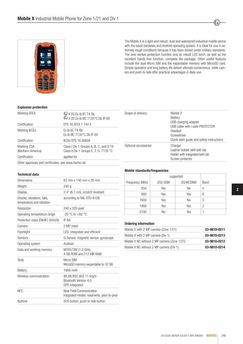
03-0330-0876/A-03/2017-BAT-398350 BARTEC 245
2
Explosion protection
Marking ATEX II 2G Ex ib IIC T4 Gb II 2D Ex ib IIIC T135°C Db IP 6X
Certification EPS 16 ATEX 1 144 X
Marking IECEx Ex ib IIC T4 Gb Ex ib IIIC T135°C Db IP 6X
Certification IECEx EPS 16.0060X
Marking CSA (Northern America)
Class I Div 1 Groups A, B, C, and D T4 Class II Div 1 Groups E, F, G T135 °C
Certification applied for
Other approvals and certificates, see www.bartec.de
Technical data
Dimensions 63 mm x 140 mm x 26 mm
Weight 240 g
Display 2.4" (6.1 cm), scratch resistant
Shocks, vibrations, falls, temperature and vibration
according to MIL-STD-8106
Resolution 240 x 320 pixel
Operating temperature range -20 °C to +60 °C
Protection class (EN/IEC 60529) IP 68
Camera 2 MP (rear)
Flashlight LED, integrated and efficient
Sensors G-Sensor, magnetic sensor, gyroscope
Operating system Android
Data and working memory MT6572M (1.3 GHz), 4 GB ROM and 512 MB RAM
Slots Micro SIM MicroSD memory expandable to 32 GB
Battery 1900 mAh
Wireless communication WLAN IEEE 802.11 b/g/n Bluetooth Version 4.0 GPS integrated
NFC Near Field Communication Integrated modes: read/write, peer-to-peer
Buttons SOS button, push-to-talk button
Scope of delivery Mobile X Battery USB charging adapter USB cable with i.safe PROTECTOR Headset Screwdriver Quick start guide and safety instructions
Optional accessories Charger Leather holster with belt clip Holder with integrated belt clipScreen protector
The Mobile X is a light and robust, dust and waterproof industrial mobile phone with the latest hardware and Android operating system. It is ideal for use in ex-tremely tough conditions because it has been tested under military standards. The lone worker protection function and an inbuilt LED torch, as well as the excellent hands-free function, complete the package. Other useful features include the dual Micro SIM and the expandable memory with MicroSD card. Simple operation and long battery life deliver ultimate convenience, while cam-era and push-to-talk offer practical advantages in daily use.
Mobile X Industrial Mobile Phone for Zone 1/21 and Div 1
Ordering information
Mobile X with 2 MP camera (Zone 1/21) 03-9810-0211
Mobile X with 2 MP camera (Div 1) 03-9810-0213
Mobile X NC without 2 MP camera (Zone 1/21) 03-9810-0212
Mobile X NC without 2 MP camera (Div 1) 03-9810-0214
Mobile standards/frequencies
supported
Frequency (MHz) (2G) GSM 3G/WCDMA Band
850 Yes No 5
900 Yes Yes 8
1800 Yes No 3
1900 Yes Yes 2
2100 No Yes 1
2

03-0330-0896-03/2017-BAT-409567/1BARTEC246
Mobile X Accessories
Ordering information
Accessories for use in potentially explosive atmosphere
Illustration Description Order no.
The accessory is approved for: - ATEX Zone 1/21 (EPS 16 ATEX 1 144 X) - IECEx Zone 1/21 (EPS 16.0060 X) - CSA Class I, II Div 1 (Certificate: applied for)
Battery for Zone 1/21 Li-Ion 3.8 V/1900 mAh (7.03 Whr)
May only be changed outside the potentially explosive atmosphere!
03-9829-0093
Battery for Div 1 Li-Ion 3.8 V/1900 mAh (7.03 Whr)
May only be changed outside the potentially explosive atmosphere!
03-9829-0094
Leather holster with belt clip (suitable for Mobile X)
Colour: black Colour: yellow
03-9829-0095 03-9829-0096
Belt clip for leather holster, 1 piece (suitable for Mobile X)
03-9829-0075
Screen protector, 1 piece (suitable for Mobile X)
03-9829-0097

03-0330-0896-03/2017-BAT-409567/2 BARTEC 247
2
Mobile X Accessories
Ordering information
Accessories for use outside potentially explosive atmosphere
Illustration Description Order no.
Charger for charging of the Mobile X with inserted battery Input voltage: AC 100 V to 240 V
Consisting of: 1 x Charger 1 x USB charging adapter 1 x USB cable with i.safe PROTECTOR
03-9829-0098
USB cable with i.safe PROTECTOR 03-9829-0077
USB charging adapter Input voltage: AC 100 V to 240 V Output voltage: DC 5 V/1 A Interface: USB type A
Can only be used for the Mobile X in combination with a USB cable with i.safe PROTECTOR!
With plug for following countries/regions: - Version: US - Version: EU - Version: UK - Version: Australia
03-9914-0014 03-9914-0015 03-9914-0016 03-9914-0017
Ordering information
Warranty extension Mobile X (1-year contract) on request


TOUCH COMPUTER/MOBILE COMPUTER


CONTENT
Lumen X4 Touch Computer B7-A2P4-2233/12210.00
252 - 253
Accessories Lumen X4 00-..; 03-..; 17-..; B7-..
254 - 255
Mobile Computer MC 92N0ex-IS for ATEX/IECEx Zone 1 and Class I, II, III Div 1 MC 92N0ex-G 17-A1A.-0G.0/SY..A600
256 - 258259
MC 92N0ex-K 17-A1A.-0K.0/SY..A600
260
MC 92N0ex RFID intern for ATEX/IECEx Zone 1 and Class I, II, III Div. 1 MC 92N0ex-G 17-A1A.-RG0./SY.QA600
MC 92N0ex-K 17-A1A.-RK0./SY.QA600
261 - 262
Accessories Mobile Computer MC 92N0ex-IS series 03-..; 05-..; 17-..
263 - 266
Mobile Computer MC 92N0ex-NI for ATEX Zone 2/22 and Class I, II, III Div 2 267 - 269
MC 92N0ex-G B7-A2A4-OG.0/SY..A600
270
MC 92N0ex-K B7-A2A4-0K.0/SY..A600
271
MC 92N0ex RFID intern for ATEX Zone 2/22 and Class I, II, III Div 2 MC 92N0ex-G B7-A2A4-RG0./SY.QA600
272 - 273
MC 92N0ex-K B7-A2A4-RK0./SY.QA600
Accessories Mobile Computer MC 92N0ex-NI series 03-..; 05-..; 17-..; B7-..
274 - 277

03-0330-0867/B-04/2017-BAT-391260/1BARTEC252
Lumen X4 from BARTEC is an extremely light, rugged and highly flexible industry touch computer for rough environments. Lumen X4 has a large number of in-ternational certifications and can be used throughout the world. It is approved for ATEX and IECEx Zone 2/22 and for CSA Class I Div. 2. Approvals for other countries are possible on customer request. Thanks to its numerous functions, the Lumen X4 provides perfect support for warehouse management, transport, service technicians, operating personnel, engineers and project managers in the field and in industry.
Lumen X4 Industrie Touch Computer
Explosion protection
Marking ATEX II 3G Ex ic IIC T5 Gc II 3D Ex ic IIIB T100 °C Dc
Certification EPS 16 ATEX 1 039 X
Marking IECEx Ex ic IIC T5 Gc Ex ic IIIB T100 °C Dc
Certification IECEx EPS 16.0016X
Marking CSA Class I Div. 2 Groups A, B, C and D T5
Certification CSA File: 70043322
Other approvals: CE, FCC, CCC. Approvals for other countries on request.
Technical data
Protection class (EN/IEC 60529)
IP 54 IP 65 for the version for use outside potentially explosive atmospheres
Storage temperature -30 °C to +60 °C
Operating temperature on starting: -10 °C to +50 °C during operation: -20 °C to +50 °C
Air humidity during operation 5 % to 95 % (non-condensing)
Processor ARM® CortexTM-A53 Quad Core 1.3 GHz
Memory 2 GB SDRAM
Storage 16 GB eMMC
Expandable memory MicroSD card up to 32 GB supported
Operating system Android 5.1 (Lollipop)
Size 4.3"
Resolution 480 x 800 pixels
Brightness 400 cd/m²
Touch function Projective capacitive multi-touch
Wireless communication WLAN-WiFi IEEE 802.11 a/b/g/nBluetooth Version 4.1 + EDRGPS integratedWWAN 4G-GSM/GPRS/EDGE/WCDMA/ HSDPA/HSUPA/LTE Includes telephone function (Exception: data transmission only within the EU)
Audio 1 x integrated microphone, 1 x loudspeaker (1 x 1.2 watts)
Internal I/O under battery 1 x Micro-SIM card slot 1 x MicroSD card slot
Externe I/0 only for use outside potentially explosive atmospheres 1 x Micro USB/Charging port (OTG host, data exchange and charging) 1 x Port for 2-slot charger (PoGo pin for charging)
Keys 1 x on/off key 1 x function key 2 x volume keys (+/-) 4 x capacitive function keys (home, menu, ESC, search function)
LED 1 x LED indicator
On starting (statt: at the start)

03-0330-0867/B-04/2017-BAT-391260/2 BARTEC 253
2
Lumen X4 Industrie Touch Computer
Sensors Brightness sensor, G-sensor, proximity sensor and eCompass
Camera front: 2 MP camera rear: 8 MP autofocus camera and LED flash
Size (length x width x height) 132.7 mm x 82 mm x 25.7 mm
Weight 280 g with battery
Battery (Type B7-A2Z0-0034) Lithium polymer battery 3.7 V/3900 mAh (1S/2P), Battery life up to 20 hrs., Charge time using USB charging adapter: up to 2.5 hrs, Charge time using USB (PC): up to 6.5 hrs Must be changed only outside potentially explosive atmosphere.
USB charging adapter Input voltage: AC 100 to 240 V Output voltage: DC 5 V/1 A/5 W
Barcode scanning (optional) 1D/2D Imager (SE4500 from Zebra)
Readable 1D codes: Code 11, Code 39, Code 93, Code 128, Codabar, Coupon Code, Chinese 2 of 5, Discrete 2 of 5, EAN-8, EAN-13, Interleaved 2 of 5, MSI, UPCA, UPCE, UPC/EAN supplementals, Trioptic 39, RSS-14, RSS Expanded, RSS Limited, Webcode
Readable 2D codes: Aztec, Australian 4-state, Canadian 4-state, Composite AB, Composite C, PDF-417, Data Matrix, Dutch Kix, Japanese 4-state, Macro PDF-417, (Macro) Micro PDF-417, Micro PDF-417, microQR, Maxi Code, QR Code, TLC39, UK 4-state, US Planet, US Postnet, USPS 4-state (US4CB)
Warranty 1 year
Service agreements available on request
Scope of delivery Lumen X4 Battery Hand strap USB charging adapter with EU and US plug Micro USB cable (type A to micro type B), Quick start guide
Optional accessories for use in potentially explosive atmospheres: Battery Screen protector MicroSD card
for use outside potentially explosive atmospheres: USB charging adapter with UK and AUS plug Micro USB host cable (OTG) 2-slot battery charger 2-slot charger
Ordering information
Lumen X4 with RFID Reader HF/NFC, without 1D/2D Imager
B7-A2P4-2233/12210000
Lumen X4 with RFID Reader HF/NFC, with 1D/2D Imager SE4500 from Zebra
B7-A2P4-2233/12210300
Technical data subject to change without notice.
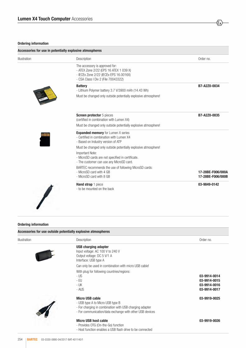
03-0330-0880-04/2017-BAT-401140/1BARTEC254
Ordering information
Accessories for use in potentially explosive atmospheres
Illustration Description Order no.
The accessory is approved for: - ATEX Zone 2/22 (EPS 16 ATEX 1 039 X) - IECEx Zone 2/22 (IECEx EPS 16.0016X) - CSA Class I Div 2 (File 70043322)
Battery - Lithium Polymer battery 3.7 V/3900 mAh (14.43 Wh)
Must be changed only outside potentially explosive atmosphere!
B7-A2Z0-0034
Screen protector 5 pieces (certified in combination with Lumen X4)
Must be changed only outside potentially explosive atmosphere!
B7-A2Z0-0035
Expanded memory for Lumen X series - Certified in combination with Lumen X4 - Based on Industry version of ATP
Must be changed only outside potentially explosive atmosphere!
Important Note: - MicroSD cards are not specified in certificate. - The customer can use any MicroSD card.
BARTEC recommends the use of following MicroSD cards: - MicroSD card with 4 GB - MicroSD card with 8 GB
17-28BE-F006/000A 17-28BE-F006/000B
Hand strap 1 piece - to be mounted on the back
03-9849-0142
Ordering information
Accessories for use outside potentially explosive atmospheres
Illustration Description Order no.
USB charging adapter Input voltage: AC 100 V to 240 V Output voltage: DC 5 V/1 A Interface: USB type A
Can only be used in combination with micro USB cable!
With plug for following countries/regions: - US - EU - UK - AUS
Micro USB cable - USB type A to Micro USB type B - For charging in combination with USB charging adapter - For communication/data exchange with other USB devices
Micro USB host cable - Provides OTG (On-the-Go) function - Host function enables a USB flash drive to be connected
03-9914-0014 03-9914-0015 03-9914-0016 03-9914-0017
03-9919-0025
03-9919-0026
Lumen X4 Touch Computer Accessories

03-0330-0880-04/2017-BAT-401140/2 BARTEC 255
2
Ordering information
Accessories for use outside potentially explosive atmospheres
Illustration Description Order no.
2-slot chargerfor charging 2 Lumen X4 - Input voltage: DC 12 V (50 W) - Charge indicator by LED and buzzer - 2 plugged chargers can be supplied with one power supply.
Further required (not included in the delivery): - Power supply - AC power cable - DC power cable
03-9914-0018
2-slot battery charger for charging 2 batteries - Input voltage: DC 12 V (50 W) - Charge indicator by LED and buzzer - 2 plugged chargers can be supplied with one power supply.
Further required (not included in the delivery): - Power supply - AC power cable - DC power cable
03-9914-0019
Power supply Input voltage: AC 100 V to 240 V Output voltage: DC 12 V/4.16 A/50 W
AC power cable, 3-wire, country-specific Version: EU Version: US
DC power cable Connection between power supply and 2-slot charger or 2-slot battery charger
03-9911-0042
03-9609-0011 03-9609-0021
03-9919-0028
Leather protective holster (suitable for Lumen X4)
03-9829-0110
Ordering information
Service
Description Order no.
Service Level Comfort (3-year contract) one-off payment 10 % of Lumen X list price for 3 years - Defined turnaround time - Product receipt/dispatch confirmation - Fast proposal management - Inspection fee included
Further details can be found in the contract documents.
Warranty extension not available
00-1191
Lumen X4 Touch Computer Accessories

03-0330-0766-10/2017-BAT-357132/1BARTEC256
Mobile Computer MC 92NOex-IS for ATEX/IECEx Zone 1 and Class I, II, III Div. 1
In close cooperation with Zebra, BARTEC has developed the MC 92 Mobile Computer for global use in potentially explosive areas, based on the successful MC 9000ex range. The device range enables complex applications to be exe-cuted, processes to be simplified and productivity boosted. Whereas barcode scanners are used for the classic collection of data, the MC 92 also offers wireless data exchange and direct further processing of data in the field. The MCs are available with a choice of different barcode scanners in order to read 1D, PDF, 2D and DPM (Device Part Marking) barcodes. The selection permits a customised adjustment that also enables barcode scanning at a distance of up to 12 m (long range). In the RFID reader area, a UHF version is also available in addition to the LF and HF versions. The RFID reader is available as an internal solution. Three versions of operating system are available. These are the fa-miliar environment of Windows® Embedded Handheld and Compact, as well as Android, the innovative, most commonly used operating system in the world. This means the user can easily adjust the devices to meet his requirements. The real time data exchange via Wi-Fi or Bluetooth is convenient, saves time and improves work processes. International approvals such as ATEX/IECEx and UL certificates as well as other national approvals such as for Brazil, South Africa, Russia etc., guarantee the worldwide use of the devices. The optimised power management and automatic shutdown via a motion sensor both guar-antee long operating times.
Technical data
Keypad design 28 numeric keys 43 numeric keys with (F) function keys 53 alphanumeric keys 53 alphanumeric keys with layout for VT emulation
Display 3.7" VGA colour display with 480 x 640 pixel touchscreen
Ambient temperature -20 °C to +40 °C
Storage temperature -40 °C to +70 °C
Charge temperature 0 °C to +40 °C
Humidity 5 % to 95 % (non-condensing)
Protection class (EN/IEC 60529)
IP 64 for Type 17-A1A2-... (UL Div 1) IP 54 for Type 17-A1A3-... (ATEX/IECEx Zone 1)
Processor TI OMAC 4430 dual-core® processor/1 GHz
Memory 1 GB/2 GB flash RAM/ROM optionally expanded with SD card (SDHC): up to 32 GB
Operating system Windows® Embedded Handheld 6.5.3 Windows® Embedded Compact 7 (CE 7.0) Android 4.4.4 (Kit Kat) with Mobility Extension (Mx) from Zebra
Power supply Lithium-ion battery with 7.4 V/2400 mAh for - Type 17-A1Z0-0001 for MC 92 Type 17-A1A3-... (ATEX/IECEx Zone 1) - Type 17-A1Z0-0002 for MC 92 Type 17-A1A2-... (UL Div. 1) Battery can be changed in the potentially explosive area.
Backup battery (installed in the device)
Ni-MH battery (rechargeable) 2.4 V/15 mAh
Interfaces RS232 and USB over Single Slot Cradle Ethernet over Ethernet-enable Cradle
Application development PSDK and EMDK for Windows and Android available from Zebra Support website
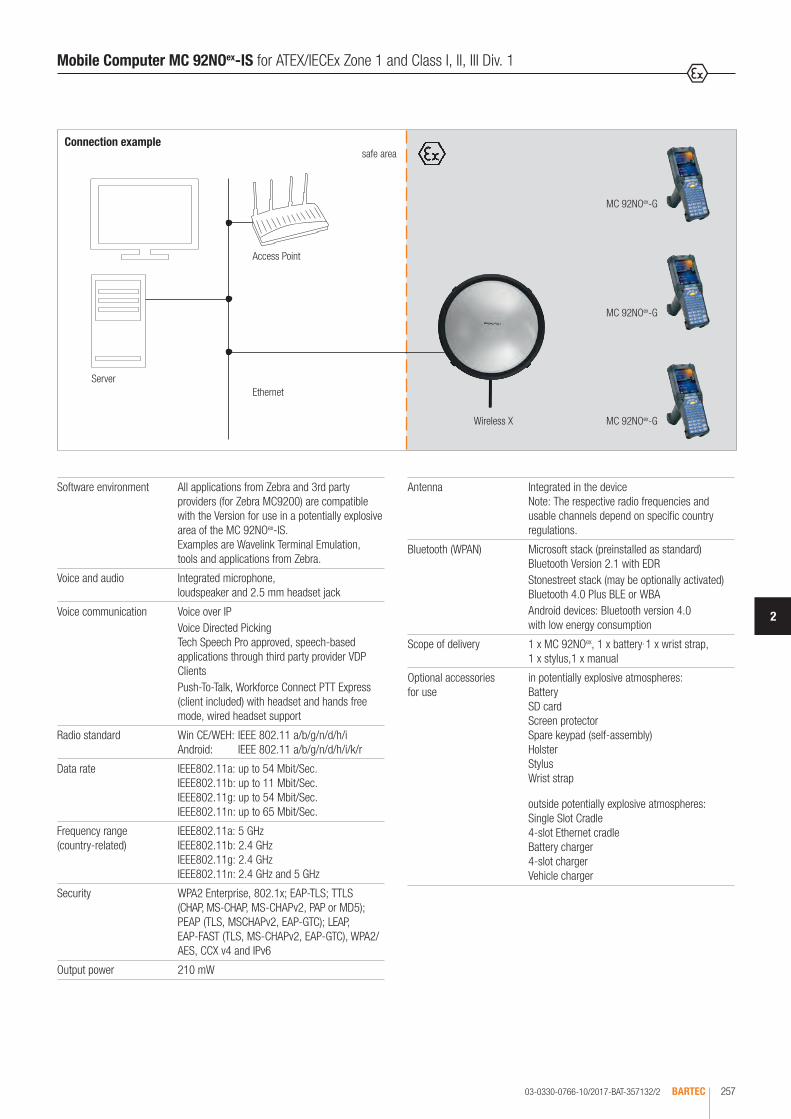
03-0330-0766-10/2017-BAT-357132/2 BARTEC 257
2
Mobile Computer MC 92NOex-IS for ATEX/IECEx Zone 1 and Class I, II, III Div. 1
Antenna Integrated in the device Note: The respective radio frequencies and usable channels depend on specific country regulations.
Bluetooth (WPAN) Microsoft stack (preinstalled as standard) Bluetooth Version 2.1 with EDRStonestreet stack (may be optionally activated) Bluetooth 4.0 Plus BLE or WBAAndroid devices: Bluetooth version 4.0 with low energy consumption
Scope of delivery 1 x MC 92NOex, 1 x battery, 1 x wrist strap, 1 x stylus,1 x manual
Optional accessories for use
in potentially explosive atmospheres: Battery SD card Screen protector Spare keypad (self-assembly) Holster Stylus Wrist strap
outside potentially explosive atmospheres: Single Slot Cradle 4-slot Ethernet cradle Battery charger 4-slot charger Vehicle charger
Software environment All applications from Zebra and 3rd party providers (for Zebra MC9200) are compatible with the Version for use in a potentially explosive area of the MC 92NOex-IS. Examples are Wavelink Terminal Emulation, tools and applications from Zebra.
Voice and audio Integrated microphone, loudspeaker and 2.5 mm headset jack
Voice communication Voice over IPVoice Directed Picking Tech Speech Pro approved, speech-based applications through third party provider VDP ClientsPush-To-Talk, Workforce Connect PTT Express (client included) with headset and hands free mode, wired headset support
Radio standard Win CE/WEH: IEEE 802.11 a/b/g/n/d/h/i Android: IEEE 802.11 a/b/g/n/d/h/i/k/r
Data rate IEEE802.11a: up to 54 Mbit/Sec. IEEE802.11b: up to 11 Mbit/Sec. IEEE802.11g: up to 54 Mbit/Sec. IEEE802.11n: up to 65 Mbit/Sec.
Frequency range (country-related)
IEEE802.11a: 5 GHz IEEE802.11b: 2.4 GHz IEEE802.11g: 2.4 GHz IEEE802.11n: 2.4 GHz and 5 GHz
Security WPA2 Enterprise, 802.1x; EAP-TLS; TTLS (CHAP, MS-CHAP, MS-CHAPv2, PAP or MD5); PEAP (TLS, MSCHAPv2, EAP-GTC); LEAP, EAP-FAST (TLS, MS-CHAPv2, EAP-GTC), WPA2/AES, CCX v4 and IPv6
Output power 210 mW
Connection examplesafe area
Server
Wireless X MC 92NOex-G
MC 92NOex-G
MC 92NOex-G
Ethernet
Access Point
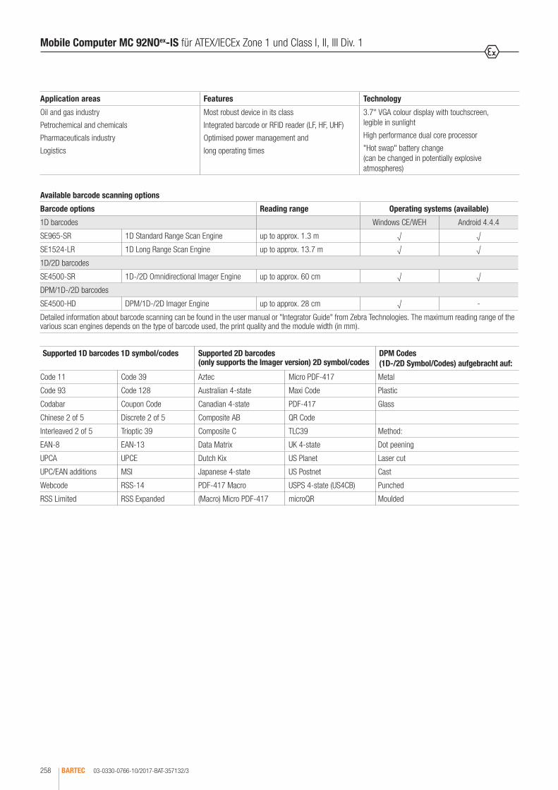
Mobile Computer MC 92NOex-IS für ATEX/IECEx Zone 1 und Class I, II, III Div. 1
03-0330-0766-10/2017-BAT-357132/3BARTEC258
Available barcode scanning options
Barcode options Reading range Operating systems (available)
1D barcodes Windows CE/WEH Android 4.4.4
SE965-SR 1D Standard Range Scan Engine up to approx. 1.3 m √ √
SE1524-LR 1D Long Range Scan Engine up to approx. 13.7 m √ √
1D/2D barcodes
SE4500-SR 1D-/2D Omnidirectional Imager Engine up to approx. 60 cm √ √
DPM/1D-/2D barcodes
SE4500-HD DPM/1D-/2D Imager Engine up to approx. 28 cm √ -
Detailed information about barcode scanning can be found in the user manual or "Integrator Guide" from Zebra Technologies. The maximum reading range of the various scan engines depends on the type of barcode used, the print quality and the module width (in mm).
Supported 1D barcodes 1D symbol/codes Supported 2D barcodes (only supports the Imager version) 2D symbol/codes
DPM Codes (1D-/2D Symbol/Codes) aufgebracht auf:
Code 11 Code 39 Aztec Micro PDF-417 Metal
Code 93 Code 128 Australian 4-state Maxi Code Plastic
Codabar Coupon Code Canadian 4-state PDF-417 Glass
Chinese 2 of 5 Discrete 2 of 5 Composite AB QR Code
Interleaved 2 of 5 Trioptic 39 Composite C TLC39 Method:
EAN-8 EAN-13 Data Matrix UK 4-state Dot peening
UPCA UPCE Dutch Kix US Planet Laser cut
UPC/EAN additions MSI Japanese 4-state US Postnet Cast
Webcode RSS-14 PDF-417 Macro USPS 4-state (US4CB) Punched
RSS Limited RSS Expanded (Macro) Micro PDF-417 microQR Moulded
Application areas Features Technology
Oil and gas industry
Petrochemical and chemicals
Pharmaceuticals industry
Logistics
Most robust device in its class
Integrated barcode or RFID reader (LF, HF, UHF)
Optimised power management and
long operating times
3.7" VGA colour display with touchscreen, legible in sunlight
High performance dual core processor
"Hot swap" battery change (can be changed in potentially explosive atmospheres)

03-0330-0766-09/2016-BAT-357132/4 BARTEC 259
2
Options for data capture
SE965-SR 1D scan engine with standard range
SE1524-LR 1D scan engine with extended range
SE4500-SR Omnidirectional 1D/2D engine for image capture of 1D and 2D symbols
SE4500-HD 1D/2D DPM engine for image capture of several DPMs on metal, plastic and glass surfaces,including dot peening, laser etching, moulding, punching or fusing procedures
MC 92NOex-G for ATEX/IECEx Zone 1 and Class I, II, III Div. 1
The MC 92NOex-G Mobile Computer with its handgrip is a robust unit for secure barcode scanning in Potentially explosive areas. The scan trigger is ideally in-tegrated in the hand-grip, enabling barcodes to be conveniently scanned. The integrated radio module ensures real time data exchange with the host system. The MC 92NOex-G combines the advantages of the Microsoft or Android plat-form with the strengths of the TI OMAC 4430 dual core® processor with 1 GHz. The large, easy to read 3.7" VGA colour display is equipped with touchscreen technology. The device operates using the IEEE 802.11 radio standards.
Explosion protection
Marking ATEX II 2G Ex q [ib] IIC T4 Gb -20 °C ≤ Ta ≤ +40 °C
Certification PTB 13 ATEX 2019X
Marking IECEx Ex q [ib] IIC T4 Gb -20 °C ≤ Ta ≤ +40 °C
Certification IECEx PTB 13.0043X
Marking UL Class I Div. 1 Group C, D T4 Ex ia Class II Div. 1 Group F, G Class III
Certification UL File E226123
Other approvals and certificates, see www.bartec.de
Technical data
Dimensions (H x W x D) 231 mm x 91 mm x 196 mm
Weight (incl. battery) Type 17-A1A3-... (ATEX/IECEx Zone 1) approx. 1060 g
Type 17-A1A2-... (UL Division 1) approx. 830 g
Complete order no. 17-A1A -OG 0/SY A600 MC 92NOex-G including Lithium-ion battery (1 piece).
* Emulation software is not included with delivery. ** only available with Windows CE/WEH operating system
Note: You will find the accessories with order details on the accessories pages. Please insert correct code. Technical data subject to change without notice.
Ordering information
Approval Code no. Barcode scanning Code no. Version Code no.
UL Div. 1 2
SE 965-SR 1D Standard Range Scan Engine
A 28 keys, numeric A
SE 1524-LR 1D Long Range Scan Engine
J 43 keys, numeric with (F) function keys
F
ATEX/IECEx Zone 1
3
SE 4500-SR 1D /2D Imager Engine
3 53 keys, alphanumeric E
SE 4500-HD** 1D /2D Imager DPM
5 53 keys, alphanumeric with layout for VT emulation*
G
Operating system Code no.
Windows® Embedded Handheld 6.5.3
Q
Windows® Embedded Compact 7 (CE 7.0)
Y
Android 4.4.4 A

03-0330-0766-10/2017-BAT-357132/5BARTEC260
Options for data capture
SE965-SR 1D scan engine with standard range
SE4500-SR Omnidirectional 1D/2D engine for image capture of 1D and 2D symbols
SE4500-HD 1D/2D DPM engine for image capture of several DPMs on metal, plastic and glass surfaces,including dot peening, laser etching, moulding, punching or fusing procedures
MC 92NOex-K for ATEX/IECEx Zone 1 and Class I, II, III Div. 1
The MC 92NOex-K Mobile Computer is a robust unit for secure barcode scanning in potentially explosive areas. The scan trigger is positioned so that barcodes can be scanned with the greatest convenience. The integrated radio module ensures real time data exchange with the host system. The MC 92NOex-K combines the advantages of the Microsoft or Android platform with the strengths of the TI OMAC 4430 dual core® processor with 1 GHz. The large, easy to read 3.7" VGA colour display is equipped with touchscreen technology. The device operates using the IEEE 802.11 radio standards.
Explosion protection
Marking ATEX II 2G Ex q [ib] IIC T4 Gb -20 °C ≤ Ta ≤ +40 °C
Certification PTB 13 ATEX 2019X
Marking IECEx Ex q [ib] IIC T4 Gb -20 °C ≤ Ta ≤ +40 °C
Certification IECEx PTB 13.0043X
Marking UL Class I Div. 1 Group C, D T4 Ex ia Class II Div. 1 Group F, G Class III
Certification UL File E226123
Other approvals and certificates, see www.bartec.de
Technical data
Dimensions (H x W x D) 231 mm x 91 mm x 59 mm
Weight (incl. battery) Type 17-A1A3-... (ATEX/IECEx Zone 1) approx. 980 g
Type 17-A1A2-... (UL Division 1) approx. 700 g
Complete order no. 17-A1A -OK 0/SY A600 MC 92NOex-K including Lithium-ion battery (1 piece).
* Emulation software is not included with delivery. ** only available with Windows CE/WEH operating system
Note: You will find the accessories with order details on the accessories pages. Please insert correct code. Technical data subject to change without notice.
Ordering information
Approval Code no.
UL Div. 1
2
ATEX/IECEx Zone 1
3
Barcode scanning Code no.
SE 965-SR 1D-Standard Range Scan Engine
A
SE 4500-SR 1D-/2D Imager Engine
3
SE 4500-HD** 1D-/2D Imager DPM
5
Version Code no.
28 keys, numeric A
43 keys, numeric with (F) function keys
F
53 keys, alphanumeric E
53 keys, alphanumeric with layout for VT emulation*
G
Operating system Code no.
Windows® Embedded Handheld 6.5.3
Q
Windows® Embedded Compact 7 (CE 7.0)
Y
Android 4.4.4 A

03-0330-0766-10/2017-BAT-357132/6 BARTEC 261
2
MC 92NOex RFID internal for ATEX/IECEx Zone 1 and Class I, II, III Div. 1
The unique concept enables barcode scanning and RFID technology to be combined in this device. Thanks to the modular keypad and colour display, data can be processed directly on the Mobile Computer. The data are transmitted to other areas of the company via WiFi or Bluetooth, so that the data are available for further processing in real time. As software for the individual application development, BARTEC offers a demo version in Open Source and an SDK file. The SDK file is available for the programming language C# and includes all necessary resources for specific application development within Windows® operating systems. The Open Source demo is used firstly to demonstrate the reading and writing of RFID tags. It also serves as a good basis for the appli-cation developer with respect to customised programming of the readers. The MC 92NOex-IS can be retrofitted in the factory with the RFID option. It cannot be retrofitted by the customer.
Explosion protection
Marking ATEX II 2G Ex q [ib] IIC T4 Gb -20 °C ≤ Ta ≤ +40 °C
II 2G Ex q [ib] IIB T4 Gb -20 °C ≤ Ta ≤ +40 °C (with mounted antenna)
Certification PTB 13 ATEX 2019X
Marking IECEx Ex q [ib] IIC T4 Gb -20 °C ≤ Ta ≤ +40 °C
Ex q [ib] IIB T4 Gb -20 °C ≤ Ta ≤ +40 °C (with mounted antenna)
Certification IECEx PTB 13.0043X
Marking UL Class I Div. 1 Group C, D T4 Ex ia Class II Div. 1 Group F, G Class III
Certification UL File E226123
Other approvals and certificates, see www.bartec.de
Technical data
Dimensions (H x W x D) MC 92NOex-G with internal RFID 234 mm x 91 mm x 196 mm
with internal RFID + mounted antenna 273 mm x 111 mm x 196 mm
MC 92NOex-K with internal RFID 234 mm x 91 mm x 59 mm
with internal RFID + mounted antenna 254 mm x 111 mm x 117 mm
Weight (including battery, depending on version and configuration)
MC 92NOex-G with internal RFID approx. 1060 g* approx. 1830 g**
with internal RFID + mounted antenna approx. 1040 g* approx. 1910 g**
MC 92NOex-K with internal RFID approx. 980 g* approx. 700 g**
with internal RFID + mounted antenna approx. 1060 g* approx. 1780 g**
* for Type 17-A1A3-... (ATEX/IECEx Zone 1) ** for Type 17-A1A2-... (UL Division 1)
Operating system Windows® Embedded Handheld 6.5.3
Note Android 4.4.4 (KitKat) and Windows® Embedded Compact 7 (CE 7.0) are not supported. Combination with the scan engine is not supported.

03-0330-0766-10/2017-BAT-357132/7BARTEC262
MC 92NOex RFID internal for ATEX/IECEx Zone 1 and Class I, II, III Div. 1
HF reader
Supported standards HF ISO 15693 e.g. I-Code SLI, Tag-IT HFI, my-d vicinity, STM LRI512 HF ISO 14443 e.g. mifare, mifare Ultra Light, my-d proximity, I-Code 1 (optional)
Read/write range HF ISO 15693 HF ISO 14443
approx. 7 cm to 12 cm approx. 1 cm to 6 cm (with tag in credit card format)
Antenna integrated
Frequency range 13.56 MHz
UHF reader
Supported standards EPC Class 1 Gen 2 tag
Read/write range approx. 30 cm to 50 cm
Antenna integrated
Frequency range Europe (EU) USA (US)
865.6 to 867.5 MHz (EN 302 208) 902.0 to 928.0 MHz (FCC CFR 47 Part 15.247)
UHF reader with mounted antenna
Supported standards EPC Class 1 Gen 2 tag
Read/write range approx. 150 cm
Antenna external (UPM Raflatac)
Frequency range Europe (EU) USA (US)
865.6 to 867.5 MHz (EN 302 208) 902.0 to 928.0 MHz (FCC CFR 47 Part 15.247)
LF reader
Supported standards HITAG S256, HITAG S 2 kbit, HITAG 1, HITAG 2, Q5, ATA5567, EM4305, HDX - RO, HDX (Multipage), EM4xxx (UNIQUE), FDX-B, BDE, ISO 117845, ISO Animal, EM 4450/4550, EM4xxx (UNIQUE), FDX-B, BDE, ISO 11784/5, ISO Animal
Read/write range approx. 5 cm
Antenna Ferrite antenna or antenna with air coil
Frequency range 125/134 kHz
Ordering information
Approval Code no.
UL Div. 1
2
ATEX/IECEx Zone 1
3
RFID internal options (without barcode scanning option) Code no.
RFID LF reader 1
RFID HF reader 3
RFID UHF (US) reader A
RFID UHF (EU) reader B
RFID UHF (US) reader with mounted antenna C
RFID UHF (EU) reader with mounted antenna D
Version Code no.
28 keys, numeric A
43 keys, numeric with (F) function keys
F
53 keys, alphanumeric E
53 keys, alphanumeric with layout for VT emulation*
G
Complete order no. Version MC 92NOex-G 17-A1A -RG0 /SY QA600MC 92NOex including Lithium-ion battery (1 piece). Version MC 92NOex-K 17-A1A -RK0 /SY QA600
* Emulation software is not included with delivery.
Note: You will find the accessories with order details on the accessories pages. Please insert correct code. Technical data subject to change without notice.

03-0330-0797-10/2017-BAT-368573/1 BARTEC 263
2
MC 92NOex-IS series Accessories
Ordering information
Accessories for use in potentially explosive atmospheres
Illustration Description Order no.
The accessory is approved for: - ATEX: Zone 1 (PTB 13 ATEX 2019 X)- IECEx: Zone 1 (IECEx PTB13.0043X)- UL: Class I, Division 1 (File E226123 weitere Zulassungen auf Anfrage
Battery - Lithium-ion battery - 7.4 V/2400 mAh - rechargeable - can be changed in the potentially explosive area - certified in combination with the MC 92NOex series - compatible with MC 9090ex series
Version: MC 92NOex-IS Type 17-A1A3-xxxx/xxxxxxxx certified for: ATEX/IECEx - Zone 1
Version: MC 92NOex-IS Type 17-A1A2-xxxx/xxxxxxxx certified for: UL Class I Div 1, UL Class II Div 1, UL Class III
17-A1Z0-0001
17-A1Z0-0002
SD card* - based on the industrial version of ATP - certified in combination with MC 92NOex series - compatible with the MC 9090ex series - can be changed in the safe area
Industrial grade SD card with - 32 GB (compatible with MC 9090ex series) - 34 GB (compatible with MC 9090ex series) - 38 GB - 16 GB - 32 GB
* Only use SD cards that have been tested by BARTEC and/or have been certified for this purpose.
17-28BE-F006/0003 17-28BE-F006/0004 17-28BE-F006/0005 17-28BE-F006/0006 17-28BE-F006/0007
Spare keypad with blue overlay - certified in combination with the MC 92NOex series - compatible with the MC 9090ex series - can be changed in the safe area
Suitable for use in the potentially explosive area: - ATEX/IECEx Zone 1 - UL Class I Div 1, UL Class II Div 1, UL Class III
Keypad variations - Keypad with 28 numeric keys - Keypad with 43 numeric keys, (F) function keys - Keypad with 53 alphanumeric keys - Keypad with 53 alphanumeric keys for VT emulation*
* Emulation software is not pre-installed on the devices.
05-0080-0438 05-0080-0440 05-0080-0441 05-0080-0442
Screen protector - certified in combination with MC 92NOex series - compatible with MC 9090ex series - can be changed in the safe area - 5 pcs per package
Suitable for use in the potentially explosive area: - ATEX Zone 1 - UL Class I Div 1, UL Class II Div 1, UL Class III
** Only use screen protectors that have been tested by BARTEC and/or have been certified for this purpose.
17-A1Z0-0004

Bestellangaben
Zubehör für den Einsatz in explosionsgefährdeten Bereichen
AbbildungBeschreibung Bestellnummer
Holster aus Leder - zugelassen in Kombination mit dem MC 92NOex-Serie - kompatibel mit der MC 9090ex-Serie - kann im sicheren Bereich gewechselt werden
Geeignet für die Verwendung im Ex-Bereich: - ATEX/IECEx Zone 1 - UL Class I Division 1, UL Class II Division 1, UL Class III
für MC 92NOex-K RFID* (Typ 17-A1Ax-RKxx/xxxxxxxx)
für MC 92NOex-G RFID* (Typ 17-A1Ax-RGxx/xxxxxxxx)
für MC 92NOex-G und MC 92NOex-K (Typ 17-A1Ax-0Gxx/xxxxxxxx)inklusive Gürtelclip/Drehteil
* Zum Tragen und Befestigen empfehlen wir einen frei wählbaren Schultergurt.
03-9809-0023
03-9809-0024
03-9809-0026
Gürtelclip/Drehteil für Holster 03-9809-0027
Schultergurt geeignet für Leder-Schutztaschen der Tablet-PC-Serie Agile und Mobile Computer MC 92 - ergonomisches, weiches Schulterpolster - verstellbare Gurtlänge
03-9829-0091
Eingabestift Geeignet für Verwendung im Ex-Bereich: - ATEX/IECEx Zone 1 für MC 92NOex-K - 13 Stück pro Packung - Farbe: gelb - 10 Stück pro Packung - Farbe: gelb - 13 Stück pro Packung, mit Gummischlaufe - Farbe: grau
für MC 92NOex-G - 13 Stück pro Packung - Farbe: grau - 10 Stück pro Packung - Farbe: gelb
verfügbare Einzelteile - 13 Stück pro Packung, Ersatz-Gummischlaufe
03-9849-0041 03-9849-0069 03-9849-0039
03-9849-0043 03-9849-0070
03-9849-0047
Handgurt Geeignet für Verwendung im Ex-Bereich: - ATEX/IECEx Zone 1 - UL Class I Div 1, UL Class II Div 1, UL Class III
für MC 92NOex-G - 3 Stück pro Packung
für MC 92NOex-K - 3 Stück pro Packung - 1 Stück Halterung für Handgurt
03-9849-0068
03-9849-0067 03-9849-0056
03-0330-0797-10/2017-BAT-368573/2BARTEC264
MC 92NOex-IS series Accessories
Ordering information
Accessories for use in potentially explosive atmospheres
Illustration Description Order no.
Leather holster - certified in combination with the MC 92NOex series - compatible with the MC 9090ex series - can be changed in the safe area
Suitable for use in the potentially explosive area: - ATEX/IECEx Zone 1 - UL Class I Div 1, UL Class II Div 1, UL Class III
for MC 92NOex-K RFID* (Type 17-A1Ax-RKxx/xxxxxxxx)
for MC 92NOex-G RFID* (Type 17-A1Ax-RGxx/xxxxxxxx)
for MC 92NOex-G und MC 92NOex-K (Type 17-A1Ax-0Gxx/xxxxxxxx) including belt clip/rotating part
* We recommend the use of a shoulder strap to wear and fasten the holster.
03-9809-0023
03-9809-0024
03-9809-0026
Belt clip/rotating part for holster
03-9809-0027
Shoulder strap suitable for leather carry case for the Agile tablet PC series and MC 92 mobile computers - ergonomic and soft shoulder pad - adjustable strap length
03-9829-0091
Stylus Suitable for use in the potentially explosive area: - ATEX/IECEx Zone 1 - UL Class I Div 1, UL Class II Div 1, UL Class III
for MC 92NOex-K - 10 pcs per package - colour: yellow - 13 pcs per package, with rubber loop - colour: grey
for MC 92NOex-G - 13 pcs per package - Colour: grau - 10 pcs per package - Colour: gelb
available individual parts - 13 pcs per package, with spare rubber loop
03-9849-0069 03-9849-0039
03-9849-0043 03-9849-0070
03-9849-0047
Wrist strap Suitable for use in the potentially explosive area: - ATEX/IECEx Zone 1 - UL Class I Div 1, UL Class II Div 1, UL Class III
for MC 92NOex-G - 3 pcs per package
Hand strap for MC 92NOex-K - 3 pcs per package
Holder for hand strap for MC 92NOex-K - 1 pcs per package
03-9849-0068
03-9849-0067 03-9849-0056

Bestellangaben
Zubehör für den Einsatz außerhalb von explosionsgefährdeten Bereichen
Abbildung Beschreibung Bestellnummer
Single Slot Cradle Set Docking-Station zur Kommunikation mit dem PC - Laden des Mobile Computers - Laden eines Ersatzakkus - zur Datensynchronisation über RS232 oder USB - zum Installieren von Software
Inklusive: - Single Slot Cradle mit Ladeschacht für Lithium-Ionen-Akku, USB Master und Slave Verbindung - RS232-Verbindungskabel Cradle <-> PC - USB-Verbindungskabel Cradle <-> PC - Netzteil AC 100 bis 240 V, DC 12 V, 16 A - AC-Netzkabel (EU) - 3-adrig Kaltgeräte Steckverbinder IEC-60320 C13 Buchse auf C14 Stecker
Benötigte Einzelteile bitte separat bestellen: AC-Netzkabel - 3-adrig - länderspezifisch
- AC-Netzkabel (US) - 3-adrig Kaltgeräte Steckverbinder IEC-60320 C13 Buchse auf NEMA 5 -15P USA Stecker
05-0079-0018
03-9915-0003 03-9919-0004 03-9919-0008 03-9911-0015 03-9609-0011
03-9609-0021
4-fach Ethernet-Cradle 4-fach Docking-Station zur Kommunikation über Ethernet - Laden von maximal 4 Mobile Computer über Ethernet - zur Datensynchronisation - zum Installieren von Software - nur kompatibel mit MC 92NOex-Serie
Hinweis: MC 92NOex mit Android-Betriebssystem unterstützen keine Ethernet-Kommunikation.
Benötigte Einzelteile bitte separat bestellen: - 4-fach Ethernet-Cradle - Netzteil für 4-fach-Cradles: AC 90 bis 264 V, DC 12 V, 9 A - DC-Verbindungskabel zur Spannungsversorgung vom Netzteil zum 4-fach-Cradle
AC-Netzkabel - 3-adrig - länderspezifisch - AC-Netzkabel (EU) - 3-adrig Kaltgeräte Steckverbinder IEC-60320 C13 Buchse auf C14 Stecker
- AC-Netzkabel (US) - 3-adrig Kaltgeräte Steckverbinder IEC-60320 C13 Buchse auf NEMA 5 -15P USA Stecker
03-9849-0026 03-9911-0021 03-9919-0010
03-9609-0011
03-9609-0021
4-fach Ladestation 4-fach-Docking-Station ohne Kommunikation zum Ethernet oder PC - Laden von maximal 4 Mobile Computer
Benötigte Einzelteile bitte separat bestellen: - 4-fach Ladestation (nur laden) - Netzteil für 4-fach Cradles: AC 90 bis 264 V, DC 12 V, 9 A - DC-Verbindungskabel zur Spannungsversorgung vom Netzteil zum 4-fach-Cradle
AC-Netzkabel - 3-adrig - länderspezifisch - AC-Netzkabel (EU) - 3-adrig Kaltgeräte Steckverbinder IEC-60320 C13 Buchse auf C14 Stecker
- AC-Netzkabel (US) - 3-adrig Kaltgeräte Steckverbinder IEC-60320 C13 Buchse auf NEMA 5 -15P USA Stecker
03-9849-0052 03-9911-0038 03-9919-0020
03-9609-0011
03-9609-0021
03-0330-0797-10/2017-BAT-368573/3 BARTEC 265
2
MC 92NOex-IS series Accessories
Ordering information
Accessories for use outside potentially explosive atmospheres
Illustration Description Order no.
Docking Station Docking station for communication with the PC - to charge the Mobile Computer - to charge a spare battery - to synchronise data via RS232 or USB - to install software
Includes: - Single slot cradle with charging shaft for Lithium-ion battery, USB master and slave connection - RS232 connecting cable Cradle <-> PC - USB connecting cable Cradle <-> PC - Power pack AC 100 - 240 V, DC 12 V, 16 A - DC connecting cable (Power supply to Cradle) - AC power cable (EU) - 3-wire - IEC connector IEC-60320 C13 socket to C14 plug
Please order the individual parts required separately: AC power cable - 3-wire - for the specific country
- AC power cable (US) - 3-wire EC connector IEC-60320 C13 socket to NEMA 5-15P USA plug
05-0079-0018
03-9915-0003 03-9919-0004 03-9919-0008 03-9911-0042 03-9919-0028 03-9609-0011
03-9609-0021
4-slot Ethernet Docking Station 4-slot docking station for communication via Ethernet - to charge a maximum of 4 Mobile Computers over Ethernet - to synchronise data - to install software - only compatible with MC 92NOex series
Note MC 92NOex with Android operating systems do not support any Ethernet communication.
Please order the individual parts required separately: - 4-slot Ethernet cradle - Power pack for 4-slot cradles: AC 90 - 264 V, DC 12 V, 9 A - DC connecting cable for power supply from the power pack to the 4-slot cradle
AC power cable - 3 wire - for the specific country - AC power cable (EU) - 3-wire IEC connector IEC-60320 C13 socket to C14 plug
- AC power cable (US) - 3-wire IEC connector IEC-60320 C13 socket to NEMA 5-15P USA plug
03-9849-0026 03-9911-0043 03-9919-0029
03-9609-0011
03-9609-0021
4-slot Docking Station 4-slot docking station without communication to the Ethernet or PC - to charge a maximum of 4 Mobile Computers
Please order the individual parts required separately: - 4-slot charger (charge only) - Power pack for 4-slot cradles: AC 90 - 264 V, DC 12 V, 9 A - DC connecting cable for power supply from the power pack to the 4-slot cradle
AC power cable - 3-wire - for the specific country - AC power cable (EU) - 3-wire IEC connector IEC-60320 C13 socket to C14 plug
- AC power cable (US) - 3-wire IEC connector IEC-60320 C13 socket to NEMA 5-15P USA plug
03-9849-0052 03-9911-0043 03-9919-0029
03-9609-0011
03-9609-0021

Bestellangaben
Zubehör für den Einsatz außerhalb von explosionsgefährdeten Bereichen
Abbildung Beschreibung Bestellnummer
4-fach Ladestation - Laden von maximal 4 Akkus
Benötigte Einzelteile bitte separat bestellen: - 4-fach Akkuladestation
- Netzteil für 4-fach Akkuladestation: AC 100 bis 240 V, DC 15 V, 5 A
- DC-Verbindungskabel zur Spannungsversorgung vom Netzteil zur 4-fach Akkuladestation
AC-Netzkabel - 3-adrig - länderspezifisch - AC-Netzkabel (EU) - 3-adrig Kaltgeräte Steckverbinder IEC-60320 C13 Buchse auf C14 Stecker
- AC-Netzkabel (US) - 3-adrig Kaltgeräte Steckverbinder IEC-60320 C13 Buchse auf NEMA 5 -15P USA Stecker
03-9849-0062
03-9911-0038
03-9919-0020
03-9609-0011
03-9609-0021
4-fach Schnellladestation UBC 2000 - Laden von maximal 4 Akkus
Inklusive: - Netzteil für 4-fach Akkuladestation: AC 100 bis 240 V, DC 15 V, 5 A
- DC Verbindungskabel zur Spannungsversorgung vom Netzteil zur 4-fach Akkuladestation
Benötigte Einzelteile bitte separat bestellen: - Akkuadapter für UBC 2000 zum Laden von Akkus der MC 9xxx Serie, maximal werden pro UBC 2000 4 Akkuadapter benötigt
AC-Netzkabel - 3-adrig - länderspezifisch - AC-Netzkabel (EU) - 3-adrig Kaltgeräte Steckverbinder IEC-60320 C13 Buchse auf C14 Stecker
- AC-Netzkabel (US) - 3-adrig Kaltgeräte Steckverbinder IEC-60320 C13 Buchse auf NEMA 5 - 15P USA Stecker
Auto-Ladeoptionen - Laden von einem Mobile Computer
- Autoladekabel - 12 V, benötigt Kabeladapter für Autoladekabel
- Autoladekabel - 24 V, benötigt Kabeladapter für Autoladekabel
Benötigte Einzelteile bitte separat bestellen: - Kabeladapter für Autoladekabel
Weiteres Zubehör erhältlich bei Zebra für die MC 9200 Serie Homepage: https://www.zebra.com/de/de.html
Zubehör-Seite: https://www.zebra.com/gb/en/products/accessories/mobile-computer.html
03-9915-0004
03-9911-0038
03-9919-0020
03-9919-0007
03-9609-0011
03-9609-0021
03-9914-0008
03-9914-0009
03-9919-0019
03-0330-0797-10/2017-BAT-368573/4BARTEC266
MC 92NOex-IS series Accessories
Ordering information
Accessories for use outside potentially explosive atmospheres
Illustration Description Order no.
4-slot Battery charger - to charge a maximum of 4 batteries
Please order the individual parts required separately: - 4-slot battery charger
- Power pack for 4-slot battery charger: AC 100 to 240 V, DC 15 V, 5 A
- DC connecting cable for power supply from the power pack to the 4-slot battery charger
AC power cable - 3-wire – for the specific country - AC power cable (EU) - 3-wire IEC connector IEC-60320 C13 socket to C14 plug
- AC power cable (US) - 3-wire IEC connector IEC-60320 C13 socket to NEMA 5-15P USA plug
03-9849-0062
03-9911-0038
03-9919-0020
03-9609-0011
03-9609-0021
Car charging options - to charge a Mobile Computer
- car charging cable - 12 V, requires cable adapter for car charging cable
- car charging cable - 24 V, requires cable adapter for car charging cable
Please order the individual parts required separately: - Cable adapter for car charging cable
Further accessories for the MC 9200 range are available from Zebra Homepage: https://www.zebra.com/de/de.html
Accessories page: https://www.zebra.com/gb/en/products/accessories/mobile-computer.html
03-9914-0008
03-9914-0009
03-9919-0019
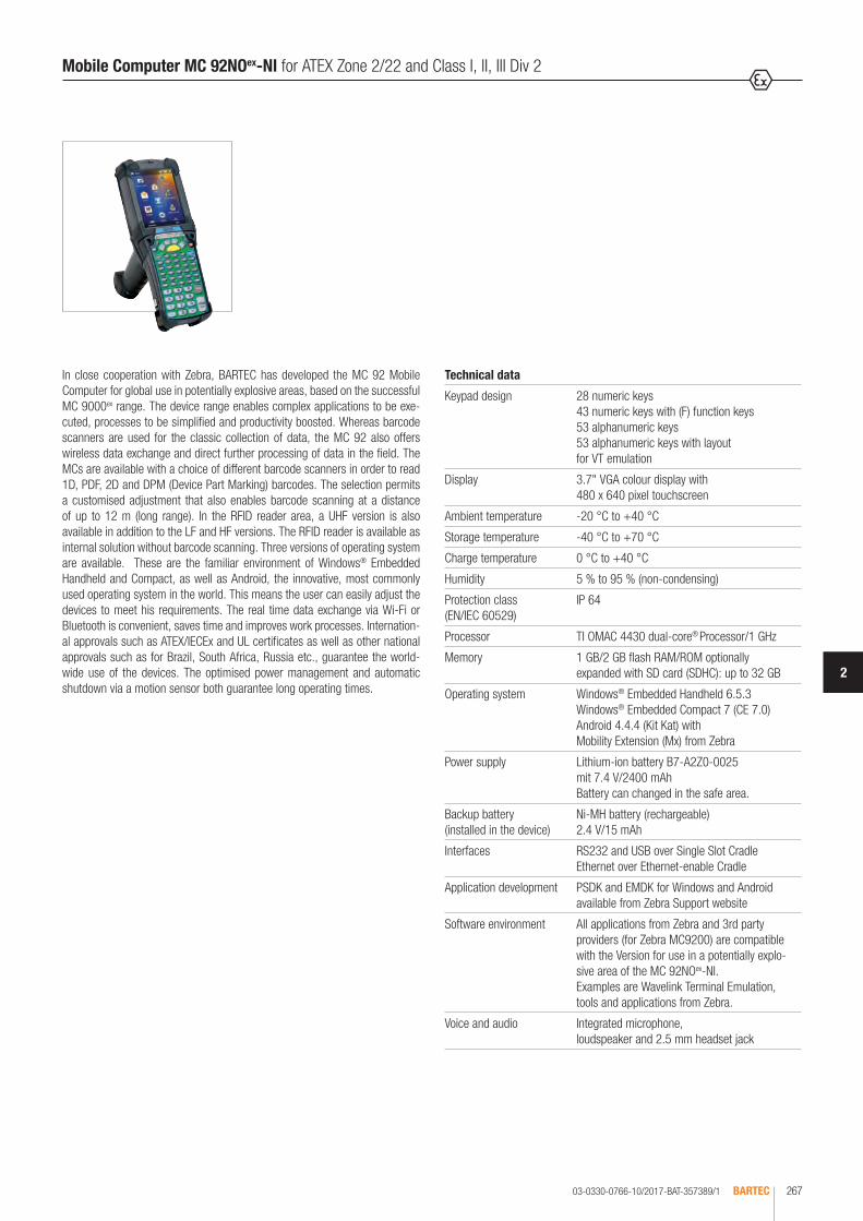
03-0330-0766-10/2017-BAT-357389/1 BARTEC 267
2
Mobile Computer MC 92NOex-NI for ATEX Zone 2/22 and Class I, II, III Div 2
In close cooperation with Zebra, BARTEC has developed the MC 92 Mobile Computer for global use in potentially explosive areas, based on the successful MC 9000ex range. The device range enables complex applications to be exe-cuted, processes to be simplified and productivity boosted. Whereas barcode scanners are used for the classic collection of data, the MC 92 also offers wireless data exchange and direct further processing of data in the field. The MCs are available with a choice of different barcode scanners in order to read 1D, PDF, 2D and DPM (Device Part Marking) barcodes. The selection permits a customised adjustment that also enables barcode scanning at a distance of up to 12 m (long range). In the RFID reader area, a UHF version is also available in addition to the LF and HF versions. The RFID reader is available as internal solution without barcode scanning. Three versions of operating system are available. These are the familiar environment of Windows® Embedded Handheld and Compact, as well as Android, the innovative, most commonly used operating system in the world. This means the user can easily adjust the devices to meet his requirements. The real time data exchange via Wi-Fi or Bluetooth is convenient, saves time and improves work processes. Internation-al approvals such as ATEX/IECEx and UL certificates as well as other national approvals such as for Brazil, South Africa, Russia etc., guarantee the world-wide use of the devices. The optimised power management and automatic shutdown via a motion sensor both guarantee long operating times.
Technical data
Keypad design 28 numeric keys 43 numeric keys with (F) function keys 53 alphanumeric keys 53 alphanumeric keys with layout for VT emulation
Display 3.7" VGA colour display with 480 x 640 pixel touchscreen
Ambient temperature -20 °C to +40 °C
Storage temperature -40 °C to +70 °C
Charge temperature 0 °C to +40 °C
Humidity 5 % to 95 % (non-condensing)
Protection class (EN/IEC 60529)
IP 64
Processor TI OMAC 4430 dual-core® Processor/1 GHz
Memory 1 GB/2 GB flash RAM/ROM optionally expanded with SD card (SDHC): up to 32 GB
Operating system Windows® Embedded Handheld 6.5.3 Windows® Embedded Compact 7 (CE 7.0) Android 4.4.4 (Kit Kat) with Mobility Extension (Mx) from Zebra
Power supply Lithium-ion battery B7-A2Z0-0025 mit 7.4 V/2400 mAh Battery can changed in the safe area.
Backup battery (installed in the device)
Ni-MH battery (rechargeable) 2.4 V/15 mAh
Interfaces RS232 and USB over Single Slot Cradle Ethernet over Ethernet-enable Cradle
Application development PSDK and EMDK for Windows and Android available from Zebra Support website
Software environment All applications from Zebra and 3rd party providers (for Zebra MC9200) are compatible with the Version for use in a potentially explo-sive area of the MC 92NOex-NI. Examples are Wavelink Terminal Emulation, tools and applications from Zebra.
Voice and audio Integrated microphone, loudspeaker and 2.5 mm headset jack

03-0330-0766-10/2017-BAT-35738/2BARTEC268
Mobile Computer MC 92NOex-NI for ATEX Zone 2/22 and Class I, II, III Div 2
Antenna Integrated in the device Note: The respective radio frequencies and usable channels depend on specific country regulations.
Bluetooth (WPAN) Microsoft stack (preinstalled as standard) Bluetooth Version 2.1 with EDRStonestreet stack (may be optionally activated) Bluetooth 4.0 Plus BLE or WBA
Android devices: Bluetooth version 4.0 with low energy
Scope of delivery 1 x MC 92NOex, 1 x battery, 1 x wrist strap, 1 x stylus, 1 x manual
Optional accessories for use
in potentially explosive atmospheres: Battery SD card Screen protector Spare keypad (self-assembly) Holster Stylus Wrist strap
outside potentially explosive atmospheres: Single Slot Cradle 4-slot Ethernet cradle Battery charger 4-slot charger Vehicle charger
Voice communication Voice over IP
Voice Directed Picking Tech Speech Pro approved, speech-based applications through third party provider VDP Clients (only with Windows operating system)
Push-To-Talk, Workforce Connect PTT Express (client included) with headset and hands free mode, wired headset support
Radio standard Win CE/WEH: IEEE 802.11 a/b/g/n/d/h/i Android: IEEE 802.11 a/b/g/n/d/h/i/k/r
Data rate IEEE802.11a: up to 54 Mbit/Sec. IEEE802.11b: up to 11 Mbit/Sec. IEEE802.11g: up to 54 Mbit/Sec. IEEE802.11n: up to 65 Mbit/Sec.
Frequency range (country-related)
IEEE802.11a: 5 GHz IEEE802.11b: 2.4 GHz IEEE802.11g: 2.4 GHz IEEE802.11n: 2.4 GHz and 5 GHz
Security WPA2 Enterprise, 802.1x; EAP-TLS; TTLS (CHAP, MS-CHAP, MS-CHAPv2, PAP or MD5); PEAP (TLS, MSCHAPv2, EAP-GTC); LEAP, EAP-FAST (TLS, MS-CHAPv2, EAP-GTC), WPA2/AES, CCX v4 and IPv6
Output power 210 mW
Connection examplesafe area
Server
Wireless X MC 92NOex-G
MC 92NOex-G
MC 92NOex-G
Ethernet
Access Point

03-0330-0766-10/2017-BAT-357389/3 BARTEC 269
2
Available barcode scanning options
Barcode options Reading range Operating systems (available)
1D barcodes Windows CE/WEH Android 4.4.4
SE965-SR 1D Standard Range Scan Engine up to approx. 1.3 m √ √
SE1524-LR 1D Long Range Scan Engine up to approx. 13.7 m √ √
1D/2D barcodes
SE4500-SR 1D/2D Omnidirectional Imager Engine up to approx. 60 cm √ √
SE4750-SR 1D/2D Omnidirectional Imager Engine up to approx. 88 cm √ √
SE4750-MR 1D/2D Omnidirectional Middle Range Imager Engine up to approx. 4.4 m √ √
SE4600-LR 1D/2D Omnidirectional Long Range Imager Engine up to approx. 9.1 m √ -
DPM/1D/2D barcodes
SE4500-HD DPM/1D/2D Imager Engine up to approx. 28 cm √ -
Detailed information about barcode scanning can be found in the user manual or "Integrator Guide" from Zebra Technologies. The maximum reading range of the various scan engines depends on the type of barcode used, the print quality and the module width (in mm).
Application areas Features Technology
Oil and gas industry
Petrochemical and chemicals
Pharmaceuticals industry
Logistics
Most robust device in its class
Integrated barcode or RFID reader (LF, HF, UHF)
Optimised power management and long operating times
3.7" VGA colour display with touchscreen, legible in sunlight
High performance dual core processor
"Hot swap" battery change (in the safe area)
Supported 1D barcodes 1D symbol/codes Supported 2D barcodes (only supports the Imager version) 2D symbol/codes
DPM Codes (1D-/2D Symbol/Codes) aufgebracht auf:
Code 11 Code 39 Aztec Micro PDF-417 Metal
Code 93 Code 128 Australian 4-state Maxi Code Plastic
Codabar Coupon Code Canadian 4-state PDF-417 Glass
Chinese 2 of 5 Discrete 2 of 5 Composite AB QR Code
Interleaved 2 of 5 Trioptic 39 Composite C TLC39 Method:
EAN-8 EAN-13 Data Matrix UK 4-state Dot peening
UPCA UPCE Dutch Kix US Planet Laser cut
UPC/EAN additions MSI Japanese 4-state US Postnet Cast
Webcode RSS-14 PDF-417 Macro USPS 4-state (US4CB) Punched
RSS Limited RSS Expanded (Macro) Micro PDF-417 microQR Moulded
Mobile Computer MC 92NOex-NI for ATEX Zone 2/22 and Class I, II, III Div 2

03-0330-0766-09/2016-BAT-357389/4BARTEC270
Options for data capture
SE965-SR 1D Scan Engine with Standard Range
SE1524-LR 1D Scan Engine with extended Range
SE4500-SR Omnidirectional 1D/2D Engine for Image Capture of 1D and 2D symbols
SE4750-SR Omnidirectional 1D/2D Engine for Image Capture of 1D and 2D symbols
SE4750-MR Omnidirectional 1D/2D Engine for Image Capture of 1D and 2D symbols with medium range
SE4600-LR Omnidirectional 1D/2D Engine for Image Capture of 1D and 2D symbols with extended range
SE4500-HD 1D/2D DPM Engine for Image Capture of several DPMs on metal, plastic and glass surfaces, including dot peening, laser etching, moulding, punching or fusing procedures
MC 92NOex-G for ATEX Zone 2/22 und Class I, II, III Div 2
The MC 92NOex-G Mobile Computer with its handgrip is a robust unit for secure barcode scanning in potentially explosive areas. The scan trigger is ideally po-sitioned on the handgrip, enabling barcodes to be conveniently scanned. The integrated radio module ensures real time data exchange with the host system. The MC 92NOex-G combines the advantages of the Microsoft or Android plat-form with the strengths of the TI OMAC 4430 dual core® processor with 1 GHz. The large, easy to read 3.7" VGA colour display is equipped with touchscreen technology. The device operates using the IEEE 802.11 radio standard.
Explosion protection
Marking ATEX II 3G Ex ic IIC T6 Gc II 3D Ex ic IIIB T80°C Dc IP 64
-20 °C ≤ Ta ≤ +50 °C
Certification PTB 13 ATEX 2019X
Marking UL Class I Div 1 Group C, D T4 Ex ia Class II Div 1 Group F, G Class III
Certification UL File E321557 Vol. 1 Sec. 5
Other approvals and certificates, see www.bartec.de
Technical data
Dimensions (H x W x D) 231 mm x 91 mm x 196 mm
Weight (incl. battery) approx. 780 g
Complete order no. B7-A2A4-OG 0/SY A60 MC 92NOex-G including Lithium-ion battery (1 piece).
* Emulation software is not included with delivery. ** only with Windows CE/WEH operating system available.
Note: You will find the accessories with order details on the accessories pages. Please insert correct code. Technical data subject to change without notice.
Version Code no.
28 keys, numeric A
43 keys, numeric with (F)-function keys
F
53 keys, alphanumeric E
53 keys, alphanumeric with layout for VT emulation*
G
Operating system Code no.Windows® Embedded Handheld 6.5.3
Q
Windows® Embedded Compact 7 (CE 7.0)
Y
Android 4.4.4 A
Ordering information
Barcode scanning Code no.
SE 965-SR 1D Standard Range Scan Engine A
SE 1524-LR 1D Long Range Scan Engine J
SE 4500-SR 1D/2D Imager Engine 3
SE 4750-SR 1D/2D Imager Engine L
SE 4750-MR 1D/2D Middle Range Imager M
SE 4500-HD** 1D/2D Imager DPM 5
SE 4600-LR** 1D/2D Long Range Imager 9

03-0330-0766-10/2017-BAT-357389/5 BARTEC 271
2
Options for data capture
SE965-SR 1D Scan Engine with Standard Range
SE4500-SR Omnidirectional 1D/2D Engine for Image Capture of 1D and 2D symbols
SE4500-HD 1D/2D DPM Engine for Image Capture of several DPMs on metal, plastic and glass surfaces, including dot peening, laser etching, moulding, punching or fusing procedures
MC 92NOex-K for ATEX Zone 2/22 and Class I, II, III Div 2
The MC 92NOex-K Mobile Computer is a robust unit for secure barcode scan-ning in potentially explosive atmospheres. The scan trigger is positioned so that barcodes can be scanned with the greatest convenience. The integrated radio module ensures real time data exchange with the host system. The MC 92NOex-K combines the advantages of the Microsoft or Android platform with the strengths of the TI OMAC 4430 dual core® processor with 1 GHz. The large, easy to read 3.7" VGA colour display is equipped with touchscreen tech-nology. The device operates using the IEEE 802.11 radio standard.
Explosion protection
Marking ATEX II 3G Ex ic IIC T6 Gc II 3D Ex ic IIIB T80°C Dc IP 64
-20 °C ≤ Ta ≤ +50 °C
Certification EPS 14 ATEX 1 782 X
Marking UL Class I Div 2 Group A, B, C, D T6 Class II Div 2 Group F, G Class III
Certification UL File E321557 Vol. 1 Sec. 5
Other approvals and certificates, see www.bartec.de
Technical data
Dimensions (H x W x D) 231 mm x 91 mm x 59 mm
Weight (incl. battery) approx. 640 g
Complete order no. B7-A2A4-OK 0/SY A600 MC 92NOex-K including Lithium-ion battery (1 piece).
* Emulation software is not included with delivery. ** only available with Windows CE/WEH operating system
Note: You will find the accessories with order details on the accessories pages. Please insert correct code. Technical data subject to change without notice.
Ordering information
Barcode scanning Code no.
SE 965-SR 1D Standard Range Scan Engine A
SE 4500-SR 1D/2D Imager Engine 3
SE 4500-HD** 1D/2D Imager DPM 5
Operating system Code no.Windows® Embedded Handheld 6.5.3
Q
Windows® Embedded Compact 7 (CE 7.0)
Y
Android 4.4.4 A
Version Code no.
28 keys, numeric A
43 keys, numeric with (F)-function keys
F
53 keys, alphanumeric E
53 keys, alphanumeric with layout for VT emulation*
G

03-0330-0766-10/2017-BAT-357389/6BARTEC272
MC 92NOex RFID internal for ATEX Zone 2/22 and Class I, II, III Div 2
The unique concept enables barcode scanning and RFID technology to be combined in this device. Thanks to the modular keypad and colour display, data can be processed directly on the Mobile Computer. The data are trans-mitted to other areas of the company via WiFi or Bluetooth, so that the data are available for further processing in real time. As software for the individual application development, BARTEC offers a demo version in Open Source and an SDK file. The SDK file is available for the programming language C# and includes all necessary resources for specific application development with-in Windows® operating systems. The Open Source demo is used firstly to demonstrate the reading and writing of RFID tags. It also serves as a good basis for the application developer with respect to customised programming of the readers. The MC 92NOex-NI can be retrofitted in the factory with the RFID option. It cannot be retrofitted by the customer.
Explosion protection
Marking ATEX II 3G Ex ic IIC T4 Gc II 3D Ex ic IIIB T130 °C Dc IP 64
-20 °C ≤ Ta ≤ +50 °C
II 3G Ex ic IIB T4 Gc II 3D Ex ic IIIB T130 °C Dc IP 64
-20 °C ≤ Ta ≤ +50 °C (with mounted antenna)
Certification EPS 14 ATEX 1 782 X
Marking UL Class I Div 2 Group A, B, C, D T4 Class II Div 2 Group F, G Class III
Certification UL File E321557 Vol. 1 Sec. 5
Other approvals and certificates, see www.bartec.de
Technical data
Dimensions (H x W x D) MC 92NOex-G with internal RFID 234 mm x 91 mm x 196 mm
with internal RFID + mounted antenna 273 mm x 111 mm x 196 mm
MC 92NOex-K with internal RFID 234 mm x 91 mm x 59 mm
with internal RFID + mounted antenna 254 mm x 111 mm x 117 mm
Weight (including battery, depending on version and configuration)
MC 92NOex-G with internal RFID approx. 780 g with internal RFID approx. 830 g + mounted antenna
MC 92NOex-K with internal RFID approx. 640 gwith internal RFID approx. 690 g + mounted antenna
Operating system Windows® Embedded Handheld 6.5.3
Note Android 4.4.4 (KitKat) and Windows® Embedded Compact 7 (CE 7.0) are not supported. Combination with the scan engine is not supported.

03-0330-0766-10/2017-BAT-357389/7 BARTEC 273
2
MC 92NOex RFID internal for ATEX Zone 2/22 and Class I, II, III Div 2
HF reader
Supported standards HF ISO 15693 e.g. I-Code SLI, Tag-IT HFI, my-d vicinity, STM LRI512 HF ISO 14443 e.g. mifare, mifare Ultra Light, my-d proximity, I-Code 1 (optional)
Read/write range HF ISO 15693 HF ISO 14443
approx. 5 cm to 6 cm approx. 4 cm to 5 cm (with tag in credit card format)
Antenna integrated
Frequency range 13.56 MHz
UHF reader
Supported standards EPC Class 1 Gen 2 tag
Read/write range approx. 30 cm to 50 cm
Antenna integrated
Frequency range Europe (EU) USA (US)
865.6 to 867.5 MHz (EN 302 208) 902.0 to 928.0 MHz (FCC CFR 47 Part 15.247)
UHF reader with mounted antenna
Supported standards EPC Class 1 Gen 2 tag
Read/write range approx. 150 cm
Antenna external (UPM Raflatac)
Frequency range Europe (EU) USA (US)
865.6 to 867.5 MHz (EN 302 208) 902.0 to 928.0 MHz (FCC CFR 47 Part 15.247)
LF reader
Supported standards HITAG S256, HITAG S 2 kbit, HITAG 1, HITAG 2, Q5, ATA5567, EM4305, HDX - RO, HDX (Multipage), EM4xxx (UNIQUE), FDX-B, BDE, ISO 117845, ISO Animal, EM 4450/4550, EM4xxx (UNIQUE), FDX-B, BDE, ISO 11784/5, ISO Animal
Read/write range approx. 5 cm
Antenna Ferrite antenna or antenna with air coil
Frequency range 125/134 kHz
Complete order no. Version MC 92NOex-G B7-A2A4-RG0 /SY QA600MC 92N0ex including Lithium-ion battery (1 piece).
Version MC 92NOex-K B7-A2A4-RK0 /SY QA600
* Emulation software is not included with delivery.
Note: You will find the accessories with order details on the accessories pages. Please insert correct code. Technical data subject to change without notice.
Version Code no.
28 keys, numeric A
43 keys, numeric with (F)-function keys F
53 keys, alphanumeric E
53 keys, alphanumeric with layout for VT emulation* G
Ordering information
RFID internal options (without barcode scanning option) Code no.
RFID LF reader 1
RFID HF reader 3
RFID UHF (US) reader A
RFID UHF (EU) reader B
RFID UHF (US) Reader with mounted antenna C
RFID UHF (EU) Reader with mounted antenna D

Bestellangaben
Zubehör für den Einsatz in explosionsgefährdeten Bereichen
Abbildung Beschreibung Bestellnummer
Akku - Lithium-Ionen-Akku - 7,4 V/2400 mAh - wiederaufladbar - kann im sicheren Bereich gewechselt werden - zugelassen in Kombination mit MC 92NOex-Serie - kompatibel mit MC 9090ex-Serie
Ausführung: MC 92NOex-NI Typ B7-A2A4-xxxx/xxxxxxxx zugelassen für: ATEX/IECEx Zone 2 und Zone 22 UL Class I Div 2, UL Class II Div 2, UL Class III
B7-A2Z0-0025
Speicherkartenerweiterung* - basierend auf der Industrieausführung von ATP - zugelassen in Kombination mit MC 92NOex-Serie - kompatibel mit MC 9090ex-Serie - kann im sicheren Bereich gewechselt werden
* SD-Karten sind nicht im Zertifikat festgeschrieben. Der Kunde kann die SD-Karte frei auswählen.
Industrial Grade SD-Karte mit (von BARTEC empfohlen) - 32 GB (kompatibel mit MC 9090ex-Serie) - 34 GB (kompatibel mit MC 9090ex-Serie) - 38 GB - 16 GB - 32 GB
17-28BE-F006/0003 17-28BE-F006/0004 17-28BE-F006/0005 17-28BE-F006/0006 17-28BE-F006/0007
Ersatztastatur mit grünem Overlay - zugelassen in Kombination mit dem MC 92NOex-Serie - kompatibel mit der MC 9090ex-Serie - kann im sicheren Bereich gewechselt werden
Geeignet für die Verwendung im Ex-Bereich - ATEX/IECEx Zone 2 und Zone 22 - UL Class I Div 2, UL Class II Div 2, UL Class III
Tastaturvarianten - Tastatur mit 28 Tasten, numerisch - Tastatur mit 43 Tasten, numerisch, (F)-Funktionstasten - Tastatur mit 53 Tasten, alphanumerisch - Tastatur mit 53 Tasten, alphanumerisch für VT-Emulation*
* Emulationssoftware ist nicht auf den Geräten vorinstalliert.
05-0080-0577 05-0080-0578 05-0080-0579 05-0080-0580
Displayschutzfolie** - zugelassen in Kombination mit MC 92NOex-Serie - kompatibel mit MC 9090ex-Serie - kann im sicheren Bereich gewechselt werden - 5 Stück pro Packung
Geeignet für die Verwendung im Ex-Bereich - ATEX/IECEx Zone 2 und 22 - UL Class I Div 2, UL Class II Div 2, UL Class III
** Ausschließlich Displayschutzfolien verwenden, die von BARTEC für diesen Zweck getestet bzw. zertifiziert sind.
17-A1Z0-0004
03-0330-0797-10/2017-BAT-403039/1BARTEC274
MC 92NOex-NI series Accessories
Ordering information
Accessories for use in potentially explosive atmospheres
Illustration Description Order no.
Battery - Lithium-ion battery - 7.4 V/2400 mAh - rechargeable - can be changed in the safe area - approved in combination with the MC 92NOex series - compatible with MC 9090ex series
Version: MC 92NOex-NI Type B7-A2A4-xxxx/xxxxxxxx approved for: ATEX/IECEx Zone 2 and Zone 22 UL Class I Div 2, UL Class II Div 2, UL Class III
B7-A2Z0-0025
SD card* - based on the industrial version of ATP - approved in combination with MC 92NOex series - compatible with the MC 9090ex series - can be changed in the safe area
* SD cards are not laid down in the certificate. The customer can choose any SD card.
Industrial grade SD cards recommended by BARTEC with - 32 GB (compatible with MC 9090ex series) - 34 GB (compatible with MC 9090ex series) - 38 GB - 16 GB - 32 GB
17-28BE-F006/0003 17-28BE-F006/0004 17-28BE-F006/0005 17-28BE-F006/0006 17-28BE-F006/0007
Alternative keypad with green overlay - approved in combination with the MC 92NOex series - compatible with the MC 9090ex series - can be changed in the safe area
Suitable for use in the potentially explosive area - ATEX/IECEx Zone 2 and Zone 22 - UL Class I Div 2, UL Class II Div 2, UL Class III
Keypad variations - Keypad with 28 numeric keys - Keypad with 43 numeric keys, (F) function keys - Keypad with 53 alphanumeric keys - Keypad with 53 alphanumeric keys for VT emulation*
* Emulation software is not preinstalled on the devices.
05-0080-0577 05-0080-0578 05-0080-0579 05-0080-0580
Screen protector** - approved in combination with MC 92NOex series - compatible with MC 9090ex series - can be changed in the safe area - 5 pcs per package
Suitable for use in the potentially explosive area - ATEX/IECEx Zone 2 und 22 - UL Class I Div 2, UL Class II Div 2, UL Class III
** Only use screen protectors that have been tested by BARTEC and/or have been certified for this purpose.
17-A1Z0-0004
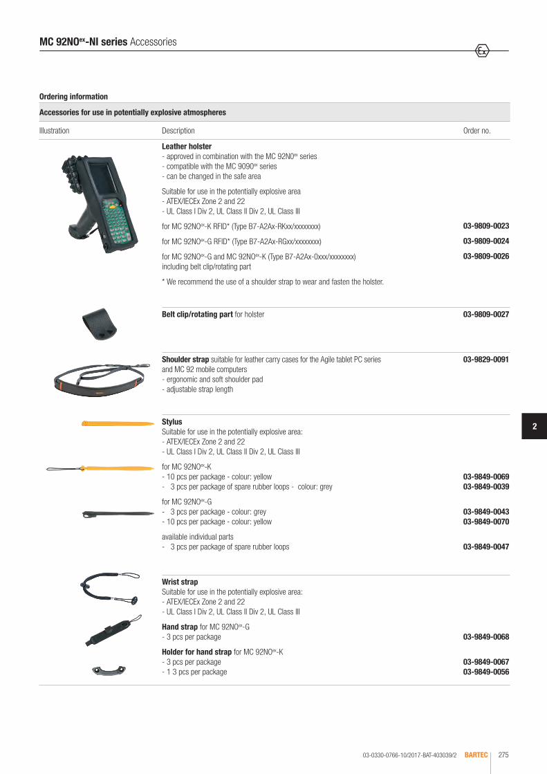
Bestellangaben
Zubehör für den Einsatz in explosionsgefährdeten Bereichen
Abbildung Beschreibung Bestellnummer
Holster aus Leder - zugelassen in Kombination mit der MC 92NOex-Serie - kompatibel mit der MC 9090ex-Serie - kann im sicheren Bereich gewechselt werden
Geeignet für die Verwendung im Ex-Bereich - ATEX/IECEx Zone 2 und 22 - UL Class I Div 2, UL Class II Div 2, UL Class III
für MC 92NOex-K RFID* (Typ B7-A2Ax-RKxx/xxxxxxxx)
für MC 92NOex-G RFID* (Typ B7-A2Ax-RGxx/xxxxxxxx)
für MC 92NOex-G und MC 92NOex-K (Typ B7-A2Ax-0xxx/xxxxxxxx) inklusive Gürtelclip/Drehteil
* Zum Tragen und Befestigen empfehlen wir einen frei wählbaren Schultergurt.
03-9809-0023
03-9809-0024
03-9809-0026
Gürtelclip/Drehteil für Holster 03-9809-0027
Schultergurt geeignet für Leder-Schutztaschen der Tablet-PC-Serie Agile und Mobile Computer MC 92 - ergonomisches, weiches Schulterpolster - verstellbare Gurtlänge
03-9829-0091
Eingabestift Geeignet für Verwendung im Ex-Bereich: - ATEX/IECEx Zone 2 und 22 - UL Class I Div 2, UL Class II Div 2, UL Class III
für MC 92NOex-K - 13 Stück pro Packung - Farbe: gelb - 10 Stück pro Packung - Farbe: gelb - 13 Stück pro Packung, mit Gummischlaufe - Farbe: grau
für MC 92NOex-G - 13 Stück pro Packung - Farbe: grau - 10 Stück pro Packung - Farbe: gelb
verfügbare Einzelteile - 13 Stück pro Packung, Ersatz-Gummischlaufe
03-9849-0041 03-9849-0069 03-9849-0039
03-9849-0043 03-9849-0070
03-9849-0047
Ersatzhandgurt Geeignet für Verwendung im Ex-Bereich: - ATEX/IECEx Zone 2 und 22 - UL Class I Div 2, UL Class II Div 2, UL Class III
für MC 92NOex-G - 3 Stück pro Packung
für MC 92NOex-K - 3 Stück pro Packung - 1 Stück Halterung für Handgurt
03-9849-0068
03-9849-0067 03-9849-0056
03-0330-0766-10/2017-BAT-403039/2 BARTEC 275
2
MC 92NOex-NI series Accessories
Ordering information
Accessories for use in potentially explosive atmospheres
Illustration Description Order no.
Leather holster - approved in combination with the MC 92N0ex series - compatible with the MC 9090ex series - can be changed in the safe area
Suitable for use in the potentially explosive area - ATEX/IECEx Zone 2 and 22 - UL Class I Div 2, UL Class II Div 2, UL Class III
for MC 92NOex-K RFID* (Type B7-A2Ax-RKxx/xxxxxxxx)
for MC 92NOex-G RFID* (Type B7-A2Ax-RGxx/xxxxxxxx)
for MC 92NOex-G and MC 92NOex-K (Type B7-A2Ax-0xxx/xxxxxxxx) including belt clip/rotating part
* We recommend the use of a shoulder strap to wear and fasten the holster.
03-9809-0023
03-9809-0024
03-9809-0026
Belt clip/rotating part for holster 03-9809-0027
Shoulder strap suitable for leather carry cases for the Agile tablet PC series and MC 92 mobile computers - ergonomic and soft shoulder pad - adjustable strap length
03-9829-0091
Stylus Suitable for use in the potentially explosive area: - ATEX/IECEx Zone 2 and 22 - UL Class I Div 2, UL Class II Div 2, UL Class III
for MC 92NOex-K - 10 pcs per package - colour: yellow - 3 pcs per package of spare rubber loops - colour: grey
for MC 92NOex-G - 3 pcs per package - colour: grey - 10 pcs per package - colour: yellow
available individual parts - 3 pcs per package of spare rubber loops
03-9849-0069 03-9849-0039
03-9849-0043 03-9849-0070
03-9849-0047
Wrist strap Suitable for use in the potentially explosive area: - ATEX/IECEx Zone 2 and 22 - UL Class I Div 2, UL Class II Div 2, UL Class III
Hand strap for MC 92NOex-G - 3 pcs per package
Holder for hand strap for MC 92NOex-K - 3 pcs per package - 1 3 pcs per package
03-9849-0068
03-9849-0067 03-9849-0056

Bestellangaben
Zubehör für den Einsatz außerhalb von explosionsgefährdeten Bereichen
Abbildung Beschreibung Bestellnummer
Single Slot Cradle Set Docking-Station zur Kommunikation mit dem PC - Laden des Mobile Computers - Laden eines Ersatzakkus - zur Datensynchronisation über RS232 oder USB - zum Installieren von Software
Inklusive: - Single Slot Cradle mit Ladeschacht für Lithium-Ionen-Akku, USB Master- und Slave-Verbindung - RS232-Verbindungskabel Cradle <-> PC - USB-Verbindungskabel Cradle <-> PC - Netzteil AC 100 bis 240 V, DC 12 V, 16 A - AC-Netzkabel (EU) - 3-adrig Kaltgeräte Steckverbinder IEC-60320 C13 Buchse auf C14 Stecker
Benötigte Einzelteile bitte separat bestellen: AC-Netzkabel - 3-adrig - länderspezifisch
- AC-Netzkabel (US) - 3-adrig Kaltgeräte Steckverbinder IEC-60320 C13 Buchse auf NEMA 5 -15P USA Stecker
05-0079-0018
03-9915-0003 03-9919-0004 03-9919-0008 03-9911-0015 03-9609-0011
03-9609-0021
4-fach-Ethernet-Cradle 4-fach Docking-Station zur Kommunikation über das Ethernet - Laden von maximal 4 Stück Mobile Computer über Ethernet - zur Datensynchronisation - zum Installieren von Software - nur kompatibel mit MC 92NOex-Serie
Hinweis: MC 92NOex mit Android-Betriebssysten unterstützen keine Ethernet-Kommunikation.
Benötigte Einzelteile bitte separat bestellen: - 4-fach Ethernet-Cradle - Netzteil für 4-fach-Cradles: AC 90 bis 264 V, DC 12 V, 9 A - DC Verbindungskabel zur Spannungsversorgung vom Netzteil zum 4-fach-Cradle
AC-Netzkabel - 3-adrig - länderspezifisch - AC-Netzkabel (EU) - 3-adrig Kaltgeräte Steckverbinder IEC-60320 C13 Buchse auf C14 Stecker
- AC-Netzkabel (US) - 3-adrig Kaltgeräte Steckverbinder IEC-60320 C13 Buchse auf NEMA 5 -15P USA Stecker
03-9849-0026 03-9911-0021 03-9919-0010
03-9609-0011
03-9609-0021
4-fach Ladestation 4-fach-Docking-Station ohne Kommunikation zum Ethernet oder PC - Laden von maximal 4 Mobile Computer
Benötigte Einzelteile bitte separat bestellen: - 4-fach-Ladestation (nur laden) - Netzteil für 4-fach-Cradles: AC 90 bis 264 V, DC 12 V, 9 A - DC-Verbindungskabel zur Spannungsversorgung vom Netzteil zum 4-fach-Cradle
AC-Netzkabel - 3-adrig - länderspezifisch - AC-Netzkabel (EU) - 3-adrig Kaltgeräte Steckverbinder IEC-60320 C13 Buchse auf C14 Stecker
- AC-Netzkabel (US) - 3-adrig Kaltgeräte Steckverbinder IEC-60320 C13 Buchse auf NEMA 5 -15P USA Stecker
03-9849-0052 03-9911-0038 03-9919-0020
03-9609-0011
03-9609-0021
03-0330-0867/B-04/2017-BAT-391260/1BARTEC276
MC 92NOex-NI series Accessories
Ordering information
Accessories for use outside potentially explosive atmospheres
Illustration Description Order no.
Docking Station Docking station for communication with the PC - to charge the Mobile Computer - to charge a spare battery - to synchronise data via RS232 or USB - to install software
Includes: - Single slot cradle with charging shaft for Lithium-ion battery, USB master and slave connection - RS232 connecting cable Cradle <-> PC - USB connecting cable Cradle <-> PC - Power pack AC 100 to 240 V, DC 12 V, 16 A - DC connecting cable (Power supply to Cradle) - AC power cable (EU) - 3-wire IEC connector IEC-60320 C13 socket to C14 plug
Please order the individual parts required separately: AC power cable - 3-wire - for the specific country
- AC power cable (US) - 3-wire IEC connector IEC-60320 C13 socket to NEMA 5-15P USA plug
05-0079-0018
03-9915-0003 03-9919-0004 03-9919-0008 03-9911-0042 03-3319-0028 03-9609-0011
03-9609-0021
4-slot Ethernet Docking Station 4-slot docking station for communication via the Ethernet - to charge a maximum of 4 Mobile Computer over the Ethernet - to synchronise data - to install software - only compatible with MC 92NOex series
Note: MC 92NOex with Android operating systems do not support any Ethernet communication.
Please order the individual parts required separately: - 4-slot Ethernet cradle - Power pack for 4-slot cradles: AC 90 to 264 V, DC 12 V, 9 A - DC connecting cable for power supply from the power pack to the 4-slot cradle
AC power cable - 3 wire - for the specific country - AC power cable (EU) - 3-wire IEC connector IEC-60320 C13 socket to C14 plug
- AC power cable (US) - 3-wire IEC connector IEC-60320 C13 socket to NEMA 5-15P USA plug
03-9849-0026 03-9911-0043 03-9919-0029
03-9609-0011
03-9609-0021
4-slot Docking Station 4-slot docking station without communication to the Ethernet or PC - to charge a maximum of 4 Mobile Computers
Please order the individual parts required separately: - 4-slot charger (charge only) - Power pack for 4-slot cradles: AC 90 to 264 V, DC 12 V, 9 A - DC connecting cable for power supply from the power pack to the 4-slot cradle
AC power cable - 3-wire - for the specific country - AC power cable (EU) - 3-wire IEC connector IEC-60320 C13 socket to C14 plug
- AC power cable (US) - 3-wire IEC connector IEC-60320 C13 socket to NEMA 5-15P USA plug
03-9849-0052 03-9911-0043 03-9919-0029
03-9609-0011
03-9609-0021

Bestellangaben
Zubehör für den Einsatz außerhalb von explosionsgefährdeten Bereichen
Abbildung Beschreibung Bestellnummer
4-fach Ladestation - Laden von maximal 4 Akkus
Benötigte Einzelteile bitte separat bestellen: - 4-fach-Akkuladestation
- Netzteil für 4-fach-Akkuladestation: AC 100 bis 240 V, DC 15 V, 5 A
- DC-Verbindungskabel zur Spannungsversorgung vom Netzteil zur 4-fach Akkuladestation
AC-Netzkabel - 3-adrig - länderspezifisch - AC-Netzkabel (EU) - 3-adrig Kaltgeräte Steckverbinder IEC-60320 C13 Buchse auf C14 Stecker
- AC-Netzkabel (US) - 3-adrig Kaltgeräte Steckverbinder IEC-60320 C13 Buchse auf NEMA 5 -15P USA Stecker
03-9849-0062
03-9911-0038
03-9919-0020
03-9609-0011
03-9609-0021
4-fach Schnellladestation UBC 2000 - Laden von maximal vier Akkus
Inklusive: - Netzteil für 4-fach-Akkuladestation: AC 100 bis 240 V, DC 15 V, 5 A
- DC Verbindungskabel zur Spannungsversorgung vom Netzteil zur 4-fach-Akkuladestation
Benötigte Einzelteile bitte separat bestellen: - Akkuadapter für UBC 2000 zum Laden von Akkus der MC 9xxx Serie, maximal werden pro UBC 2000 vier Akkuadapter benötigt
AC-Netzkabel - 3-adrig - länderspezifisch - AC-Netzkabel (EU) - 3-adrig Kaltgeräte Steckverbinder IEC-60320 C13 Buchse auf C14 Stecker
- AC-Netzkabel (US) - 3-adrig Kaltgeräte Steckverbinder IEC-60320 C13 Buchse auf NEMA 5 - 15P USA Stecker
Auto-Ladeoptionen - Laden von einem Mobile Computer
- Autoladekabel - 12 V, benötigt Kabeladapter für Autoladekabel
- Autoladekabel - 24 V, benötigt Kabeladapter für Autoladekabel
Benötigte Einzelteile bitte separat bestellen: - Kabeladapter für Autoladekabel
Weiteres Zubehör erhältlich bei Zebra für die MC 9200 Serie Homepage: https://www.zebra.com/de/de.html
Zubehör-Seite: https://www.zebra.com/gb/en/products/accessories/mobile-computer.html
03-9915-0004
03-9911-0038
03-9919-0020
03-9919-0007
03-9609-0011
03-9609-0021
03-9914-0008
03-9914-0009
03-9919-0019
03-0330-0867/B-04/2017-BAT-391260/2 BARTEC 277
2
MC 92NOex-NI series Accessories
Ordering information
Accessories for use outside potentially explosive atmospheres
Illustration Description Order no.
4-slot battery charger - to charge a maximum of 4 batteries
Please order the individual parts required separately: - 4-slot battery charger
- Power pack for 4-slot battery charger: AC 100 - 240 V, DC 15 V, 5 A
- DC connecting cable for power supply from the power packto the 4-slot battery charger
AC power cable - 3-wire – for the specific country - AC power cable (EU) - 3-wire IEC connector IEC-60320 C13 socket to C14 plug
- AC power cable (US) - 3-wire IEC connector IEC-60320 C13 socket to NEMA 5-15P USA plug
03-9849-0062
03-9911-0038
03-9919-0020
03-9609-0011
03-9609-0021
Car charging options - to charge a Mobile Computer
- car charging cable - 12 V, requires cable adapter for car charging cable
- car charging cable - 24 V, requires cable adapter for car charging cable
Please order the individual parts required separately: - Cable adapter for car charging cable
Further accessories for the MC 9200 range are available from Zebra Homepage: https://www.zebra.com/de/de.html
Accessories page: https://www.zebra.com/gb/en/products/accessories/mobile-computer.html
03-9914-0008
03-9914-0009
03-9919-0019


DATA CAPTURE


CONTENT
RFID X IS handheld reader for Zone 1/21 17-A1R4-1.00/0000
282
RFID X NI handheld reader for Zone 2/22 B7-A2R4-1.00/0000
283

03-0330-0898-04/2017-BAT-410908BARTEC282
The RFID X IS is a handheld reader for easily and efficiently reading RFID/NFC tags via direct application or in difficult-to-reach places. The tag information can be read directly on the OLED display, transferred via Bluetooth or read from the internal memory via USB.
RFID X IS handheld reader for Zone 1/21
Explosion protection
Marking ATEX Zone 1/21 II 2G Ex ib IIC T4 Gb II 2D Ex ib IIIC T135°C Db IP 6X
Certification EPS 16 ATEX 1119
Marking IECEx Zone 1/21Ex ib IIC T4 GbEx ib IIIC T135°C Db IP 6X
Certification IECEx EPS 16.0052X
Technical data
Dimensions (L x H x W) 190 mm x 30 mm x 35 mm
Weight 130 g
Bluetooth® 4.0 LE
Memory 1000 readings (UID + date + time)
Battery Ni-MH 1000 mAh
Display OLED, 4 rows
Protection class IP 64
Operating temperature -20 °C to +60 °C
Scope of delivery RFID X IS, USB cable, quick start guide and safety information
RFID standards supported
Frequency range Reading distance RFID/NFC Tag
LF 125 kHz up to 30 mm ISO: De-Facto Standard (EM4200, Hitag S 2048)
LF 134 kHz up to 30 mm ISO: 11784, 11785 (TI HDX, FSK 64 bit Read Only Singe Page IC, EM4305 FDX-B)
HF 13.56 MHz up to 20 mm ISO: 15693, 18000-3 (NXP I-Code SLIX, Infineon my-d vicinity SRF55V10P)
HF 13.56 MHz up to 10 mm ISO: 14443, 18000-3 (NXP MIFARE Classic 1K or 4K, NXP NTAG213, NXP NTAG216)
UHF 860 MHz to 960 MHz
up to 150 mm ISO: 18000-6 (Alien Higgs 3 conforming to the EPC Class1 Gen 2 standard)
The precise reading range depends on the RFID tag, mounting surface, ambient conditions, etc.
Ordering information
Handheld reader RFID X IS Order no.
with Bluetooth LF Reader 17-A1R4-1100/0000
with Bluetooth HF Reader 17-A1R4-1200/0000
with Bluetooth UHF Reader 17-A1R4-1300/0000
with Bluetooth LF/HF Reader 17-A1R4-1400/0000
with Bluetooth LF/UHF Reader 17-A1R4-1500/0000
with Bluetooth HF/UHF Reader 17-A1R4-1600/0000
with Bluetooth LF/HF/UHF Reader 17-A1R4-1700/0000
Technical data subject to change without notice.

03-0330-0899-04/2017-BAT-410909 BARTEC 283
2
The RFID X NI is a handheld reader for easily and efficiently reading RFID/NFC tags via direct application or in difficult-to-reach places. The tag information can be read directly on the OLED display, transferred via Bluetooth or read from the internal memory via USB.
RFID X NI handheld reader for Zone 2/22
Explosion protection
Marking ATEX Zone 2/22 II 3G Ex ic IIC T4 Gc IP 54 II 3D Ex ic IIIB T135°C Dc IP 54
Certification EPS 16 ATEX 1067 X
Marking IECEx Zone 2/22Ex ic IIC T4 Gc IP 54Ex ic IIIB T135°C Dc IP 54
Certification IECEx EPS 16.0026X
RFID standards supported
Frequency range Reading distance RFID/NFC Tag
LF 125 kHz up to 30 mm ISO: De-Facto Standard (EM4200, Hitag S 2048)
LF 134 kHz up to 30 mm ISO: 11784, 11785 (TI HDX, FSK 64 bit Read Only Singe Page IC, EM4305 FDX-B)
HF 13.56 MHz up to 20 mm ISO: 15693, 18000-3 (NXP I-Code SLIX, Infineon my-d vicinity SRF55V10P)
HF 13.56 MHz up to 10 mm ISO: 14443, 18000-3 (NXP MIFARE Classic 1K or 4K, NXP NTAG213, NXP NTAG216)
UHF 860 MHz to 960 MHz
up to 150 mm ISO: 18000-6 (Alien Higgs 3 conforming to the EPC Class1 Gen 2 standard)
The precise reading range depends on the RFID tag, mounting surface, ambient conditions, etc.
Technical data
Dimensions (L x H x W) 190 mm x 30 mm x 35 mm
Weight 130 g
Bluetooth® 4.0 LE
Memory 1000 readings (UID + date + time)
Battery Ni-MH 1000 mAh
Display OLED, 4 rows
Protection class IP 64
Operating temperature -20 °C to +60 °C
Scope of delivery RFID X NI, USB cable, quick start guide and safety information
Ordering information
Handheld reader RFID X NI Order no.
with Bluetooth LF Reader B7-A2R4-1100/0000
with Bluetooth HF Reader B7-A2R4-1200/0000
with Bluetooth UHF Reader B7-A2R4-1300/0000
with Bluetooth LF/HF Reader B7-A2R4-1400/0000
with Bluetooth LF/UHF Reader B7-A2R4-1500/0000
with Bluetooth HF/UHF Reader B7-A2R4-1600/0000
with Bluetooth LF/HF/UHF Reader B7-A2R4-1700/0000
Technical data subject to change without notice.

BARTEC284
Subject Index
Subject Type number Page
AC/DC converter DC 24 V/450 mA 07-7311-97S7/AAMO 199
Accessories Agile X 00-..; 03-..; B7-.. 222 - 226
Accessories Agile X IS 00-..; 03-..; 17-..
Accessories for POLARIS BASIC 04-..; 05-..; 07-..; 17-.. 97 - 98
Accessories for POLARIS COMFORT 02-..; 04-..; 05-..; 07-..; 17-.. 86 - 87
Accessories for POLARIS PROFESSIONAL 02-..; 04-..; 05-..; 07-..; 17-.. 42 - 45
Accessories for POLARIS REMOTE 02-..; 03-..; 04-..; 05-.. 74 - 77
Accessories Gravity X 00-..; 03-.. 236 - 237
Accessories Impact X 00-..; 03-.. 243 - 244
Accessories Lumen X4 00-..; 03-..; 17-..; B7-.. 254 - 255
Accessories Lumen X7 00-..; 03-..; 17-..; B7-.. 229 - 230
Accessories Mobile Computer MC 92N0ex-IS series 03-..; 05-..; 17-.. 267 - 269
Accessories Mobile Computer MC 92N0ex-NI series 03-..; 05-..; 17-..; B7-.. 274 - 277
Accessories Mobile X 03-.. 246 - 247
Accessories Orbit X 03-.. 240
Agile X IS, Industry Tablet PC 10.1" for Zone 1 17-A1B4-1..1/221.1.00 212 - 213
Agile X, Industry Tablet PC 10.1" B7-A234-40.1/111...00 218 - 219
ANTARES Accessories 02-..; 03-..; 05-..; 17-.. 124
ANTARES Connection Module 17-5164-9..0 102 - 103
ANTARES Head Module 17-5174-1.00 102 - 103
ANTARES RCU (Rail Control Unit) 17-51.. 102 - 103
ANTARES Remote I/O Module 16DI-N 17-6143-1008/0000 106 -107
ANTARES Remote I/O Module 4AIO 17-6143-1006/0000 116 - 117
ANTARES Remote I/O Module 4AIOH 17-6143-1007/0000 118 - 119
ANTARES Remote I/O Module 4TI 17-6143-1003/0000 120 - 121
ANTARES Remote I/O Module 8AI 17-6143-1004/0000 112 - 113
ANTARES Remote I/O Module 8AIH 17-6143-1005/0000 114 - 115
ANTARES Remote I/O Module 8DI-N 17-6143-1002/0000 104 - 105
ANTARES Remote I/O Module 8DO 17-6143-1001/0000 110 - 111
ANTARES Remote I/O Module 8DO-SCL 17-6143-1010/0000 108 - 109
ANTARES Remote I/O Module 8TC 17-6143-1014/0000 122 - 123
Cradle relay AC 07-7331-977./.100 194 - 195
Cradle relay DC 07-7331-977./.100 196 - 197
Enclosure for mouse and keyboard for POLARIS REMOTE 05-0041-0277 72
Enclosure for mouse and keyboard POLARIS PROFESSIONAL 05-0041-0277 40
Ex i memory stick for POLARIS SMART HMI 7" W 17-A1Z0-0007 38
Freewheeling diode, double 07-7311-63GF/5300 183
Freewheeling diode, single 07-7311-61GF/54.0 182
Fuse up to 1.25 A with double terminals 07-7311-61J2/..20 177
Fuse up to 1.25 A with single terminals 07-7311-61J2/.TA0 178
Fuse up to 2.5 A 07-7311-63J2/..00 179
Fuse up to 6.3 A 07-7311-93J2/..00 180
Fuse up to 6.3 A, quick-acting 07-7311-93J2/..00 181
Gravity X, intrinsically safe camera 17-K113-1012111.0000 234 - 235
HART Add-on module for Agile X tablet PC for ATEX/IECEx Zone 1 17-A1Z0-0005 220
HART Add-on module for Agile X tablet PC for the Non-Ex area G7-A0Z0-0007 220
HART Add-on module for Agile X tablet PC for ATEX/IECEx Zone 2 B7-A2Z0-0033 220
Impact X, Intrinsically Safe Smartphone 17-S123-1112111.0000 241 - 242
Input devices for POLARIS COMFORT 17-71VZ-.000 85
Input devices for POLARIS PROFESSIONAL 17-71VZ-40.0; 17-71VZ-.000 40 - 41
Input devices for POLARIS REMOTE 17-71VZ-40.0; 17-71VZ-.000 72 - 73
IP 30 isolator terminal, 2-pole 07-7311-6131/EE00 176
Isolator amplifier, 4-channel with display 07-7311-97MT/BA.. 204 - 205
Isolator relay, galv. insulation acc. to EN/IEC 60079-0 and EN/IEC 60079-11 07-7311-937./..00 192 - 193
Lamp test circuit 07-7311-97GW/E3K0 185
Lumen X4, Touch Computer B7-A2P4-2233/12210.00 252 - 253
Lumen X7, Industry Tablet PC B7-A234-2043/44330000; B7-A234-2343/44330000 227 - 228
MC 92N0ex RFID intern for ATEX Zone 2/22 and Class I, II, III Div 2 B7-A2A4-.. 272 - 273
MC 92N0ex RFID intern for ATEX/IECEx Zone 1 and Class I, II, III Div. 1 17-A1A. 261 - 262
MC 92N0ex-G for ATEX/IECEx Zone 1 17-A1A.-0G.0/SY..A600 259
212 - 213

BARTEC 285
Subject Index
Subject Type number Page
MC 92N0ex-G RFID intern 17-A1A.-RG0./SY.QA600 261 - 262
MC 92N0ex-G for ATEX Zone 2/22 B7-A2A4-OG.0/SY..A600 270
MC 92N0ex-G RFID intern B7-A2A4-RG0./SY.QA600 272 - 273
MC 92N0ex-K for ATEX/IECEx Zone 1 17-A1A.-0K.0/SY..A600 260
MC 92N0ex-K RFID intern 17-A1A.-RK0./SY.QA600 263 - 266
MC 92N0ex-K for ATEX Zone 2/22 B7-A2A4-0K.0/SY..A600 271
MC 92N0ex-K RFID intern B7-A2A4-RK0./SY.QA600 272 - 273
Measuring resistor max. 0.8 Watt 07-7311-61TW/..00 184
Measuring transducer for Pt100, galvanically isolated 07-7311-93T5/.350 206
Miniature switching relay 07-7311-6371/.000 188
Mobile Computer MC 92N0ex-IS for ATEX/IECEx Zone 1 and Class I, II, III Div 1 17-A1A. 256 - 266
Mobile Computer MC 92N0ex-NI for ATEX Zone 2/22 and Class I, II, III Div 2 B7-A2A. 267 - 269
Mobile X, Industrial Mobile Phone for Zone 1/21 and Div 1 17-S113-1.00 245
Optocoupler, 2-channel 07-7311-93QH/C5M0 203
Orbit X, explosion-proof Wi-Fi camera 17-K123-1012111.0000 238 - 239
Overview device series POLARIS BASIC 17-…. 13
Overview device series POLARIS COMFORT 17-…. 12
Overview device series POLARIS REMOTE and POLARIS REMOTE ZeroClient 17-…. 10 - 11
Overview device series POLARIS SMART HMI and POLARIS PROFESSIONAL 17-…. 8 - 9
POLARIS Control 17-71V0-000. 88 - 89
POLARIS II Panel PC 19.1" 17-72V4-...2/..00 32 - 33
POLARIS II Panel PC 22" W 17-72V4-...2/..00 34 - 35
POLARIS II Panel PC 24" W 17-7.V4-8..2/..00 36 - 37
POLARIS II Remote 19.1" 17-7.V5-..0./..00 66 - 67
POLARIS II Remote 22" W 17-7.V5-..0./..00 68 - 69
POLARIS II Remote 24" W 17-7.V5-8.0./..00 70 - 71
POLARIS Panel PC 10.4" 17-71V1-90../.0000.00 16 - 17
POLARIS Panel PC 10.4" 17-71V1-20.. 92 - 93
POLARIS Panel PC 12.1" 17-71V1-80../.0000.00 18 - 19
POLARIS Panel PC 12.1" 17-71V1-30.. 94 - 95
POLARIS Panel PC 12.1" W 17-71V1-B.../.0000.00 20 - 21
POLARIS Panel PC 15" 17-71V1-.0../.000..00 22 - 23
POLARIS Panel PC 15" Sunlight 17-71V1-.2../.000..00 24 - 25
POLARIS Panel PC 17.3" W 17-71V1-.0../.000..00 26 - 27
POLARIS Panel PC 19.1" 17-71V1-.0../.000..00 28 - 29
POLARIS Panel PC 24" W 17-71V1-.0../.000..00 30 - 31
POLARIS Panel PC 5.7" 17-71V1-10.. 90 - 91
POLARIS Remote 15" 17-71V2-.0../00.0 46 - 47
POLARIS Remote 15" Sunlight 17-71V2-.0../00.0 48 - 49
POLARIS Remote 19.1" 17-71V2-.0../00.0 50 - 51
POLARIS Remote 24" W 17-71V2-.0../00.0 52 - 53
POLARIS SMART HMI 7" W 17-71V6-1.../0.00 14 - 15
POLARIS Touch Panel 10.4" 17-71V1-90../X000 80 - 81
POLARIS Touch Panel 12.1" 17-71V1-80../X000 82 - 83
POLARIS Touch Panel 5.7" 17-71V1-A0../X000 78 - 79
POLARIS ZeroClient 12.1" W 17-71V1-B436/Z000 54 - 55
POLARIS ZeroClient 15" 17-71V1-.072/Z000/.200 56 - 57
POLARIS ZeroClient 15" Sunlight 17-71V1-6272/Z000/.200 58 - 59
POLARIS ZeroClient 17.3" W 17-71V1-.072/Z000/.200 60 - 61
POLARIS ZeroClient 19.1" 17-71V1-.072/Z000/.200 62 - 63
POLARIS ZeroClient 24" W 17-71V1-.072/Z000/.200 64 - 65
Power contactor 07-7311-97ER/31.0 207
Power relay 07-7311-9772/.310 191
Power Supply, 100 W for Zone 1 + 2 and Zone 21 + 22 07-7381-1.00 202
Power supply unit AC/DC 110 to 250 V 07-7311-97S9/J..0 201
Power supply unit DC 24 V/2 A 07-7331-1201/0000 200
Process Monitor PM 420ex 17-71MM-1002 172
PROFIBUS Interface 16 x Ex e digital out 07-7331-2301/0000 130 - 131
PROFIBUS Interface 8 x 4 to 20 mA in/4 x 4 to 20 mA in/out (15-bit plus sign) Ex i 07-7331-230H/.0.1 156 - 157
PROFIBUS Interface 8 x 4 to 20 mA in/4 x 4 to 20 mA in/out (16-bit) 07-7331-230H/.0.0 158 - 159

BARTEC286
PROFIBUS-DP Coupler 07-7311-9.WP/K.NO 160 - 161
PROFIBUS-DP Gateway DP/IS 07-7311-97WP/K.EO 160 - 161
PROFIBUS-DP Repeater 07-7311-93WP/R.NO 160 - 161
PROFIBUS-Interface 16 NAMUR in (16 x digital in Ex i) 07-7331-2303/0000, 07-7331-2303/1000 136 - 137
PROFIBUS-Interface 16 x digital in Ex e 07-7331-2302/0000 134 - 135
PROFIBUS-Interface 16 x digital out Ex i 07-7331-2301/1.00 132 - 133
PROFIBUS-Interface 4 x digital out Ex e/8 x digital in Ex i (NAMUR) 07-7331-2305/0000 144 - 145
PROFIBUS-Interface 4 x digital out Ex i/8 x digital in Ex i (NAMUR) 07-7331-2305/1000 146 - 147
PROFIBUS-Interface 4 x RTD in Ex i 07-7331-2307/0000 150 - 151
PROFIBUS-Interface 8 x 4 to 20 mA in Ex i 07-7331-2304/0000 138 - 139
PROFIBUS-Interface 8 x 4 to 20 mA in passive Ex e 07-7331-2304/2000 140 - 141
PROFIBUS-Interface 8 x 4 to 20 mA out Ex i/Ex e 07-7331-2306/.000 148 - 149
PROFIBUS-Interface 8 x 4 to 20 mA, Transmitter in Ex e 07-7331-2304/3000 142 - 143
PROFIBUS-Interface 8 x Relay out Ex e 07-7331-2308/0000 152 - 153
PROFIBUS-Interface 8 x Relay out Ex i 07-7331-2308/1000 154 - 155
PROFIBUS-Interface Terminator 07-7311-93WP/0000 168
Relay, 1 changeover contact/2 changeover contacts 07-7311-937./.000 189 - 190
Resistive coupling element 17-9Z62-00.. 169 - 170
Resistive coupling element 1 kΩ/10 kΩ 17-9Z63-0002 171
Resistors max. 1.2 Watt 07-7311-63TW/.... 186 - 187
RFID UHF Add-on module for Agile X tablet PC B7-A2Z0-0032 221
RFID X IS handheld reader for Zone 1/21 17-A1R4-1.00/0000 282
RFID X NI handheld reader for Zone 2/22 B7-A2R4-1.00/0000 283
RS485/PROFIBUS Optical fibre branch coupler 07-7311-97WP/60.0 166 - 167
RS485/PROFIBUS Optical fibre T-coupler 07-7311-97WP/40.0 162 - 163
RS485/PROFIBUS Optical fibre Ring-coupler 07-7311-97WP/54.0 164 - 165
Smart Tastatur for POLARIS SMART HMI 7" W 17-71VZ-C011 38
Software ANTARES Designer 17-28TF-0074 125
Transformer AC 24 V/500 mA 07-7311-97S3/H3N0 198
USB Smart Devices, Bluetooth 17-71VZ-A020 39
USB Smart Devices, WLAN 17-71VZ-A010 39
Visualisation software BMS-Graf-pro 6 17-28TF-0071/0.00 96
Visualisation software BMS-Graf-pro 7 17-28TF-0075 84
Subject Index/Type Index
Subject Type number Page
Type number Subject Page
00-..; 03-.. Accessories Gravity X 236 - 23700-..; 03-.. Accessories Impact X 243 - 24400-..; 03-..; 17-.. Accessories Agile X IS 00-..; 03-..; 17-..; B7-.. Accessories Lumen X4 254 - 25500-..; 03-..; 17-..; B7-.. Accessories Lumen X7 229 - 23000-..; 03-..; B7-.. Accessories Agile X 222 - 22602-..; 03-..; 04-..; 05-.. Accessories for POLARIS REMOTE 74 - 7702-..; 03-..; 05-..; 17-.. ANTARES Accessories 12402-..; 04-..; 05-..; 07-..; 17-.. Accessories for POLARIS COMFORT 86 - 8702-..; 04-..; 05-..; 07-..; 17-.. Accessories for POLARIS PROFESSIONAL 42 - 4503-.. Accessories Mobile X 246 - 24703-.. Accessories Orbit X 24003-..; 05-..; 17-.. Accessories Mobile Computer MC 92N0ex-IS series 267 - 26903-..; 05-..; 17-..; B7-.. Accessories Mobile Computer MC 92N0ex-NI series 274 - 27704-..; 05-..; 07-..; 17-.. Accessories for POLARIS BASIC 97 - 9805-0041-0277 Enclosure for mouse and keyboard for POLARIS REMOTE 7205-0041-0277 Enclosure for mouse and keyboard POLARIS PROFESSIONAL 4007-7311-6131/EE00 IP 30 isolator terminal, 2-pole 17607-7311-61GF/54.0 Freewheeling diode, single 18207-7311-61J2/..20 Fuse up to 1.25 A with double terminals 17707-7311-61J2/.TA0 Fuse up to 1.25 A with single terminals 17807-7311-61TW/..00 Measuring resistor max. 0.8 Watt 18407-7311-6371/.000 Miniature switching relay 18807-7311-63GF/5300 Freewheeling diode, double 18307-7311-63J2/..00 Fuse up to 2.5 A 179
222 - 226

BARTEC 287
07-7311-63TW/.... Resistors max. 1.2 Watt 186 - 18707-7311-9.WP/K.NO PROFIBUS-DP Coupler 160 - 16107-7311-937./..00 Isolator relay, galv. insulation acc. to EN/IEC 60079-0 and EN/IEC 60079-11 192 - 19307-7311-937./.000 Relay, 1 changeover contact/2 changeover contacts 189 - 19007-7311-93J2/..00 Fuse up to 6.3 A 18007-7311-93J2/..00 Fuse up to 6.3 A, quick-acting 18107-7311-93QH/C5M0 Optocoupler, 2-channel 20307-7311-93T5/.350 Measuring transducer for Pt100, galvanically isolated 20607-7311-93WP/0000 PROFIBUS-Interface Terminator 16807-7311-93WP/R.NO PROFIBUS-DP Repeater 160 - 16107-7311-9772/.310 Power relay 19107-7311-97ER/31.0 Power contactor 20707-7311-97GW/E3K0 Lamp test circuit 18507-7311-97MT/BA.. Isolator amplifier, 4-channel with display 204 - 20507-7311-97S3/H3N0 Transformer AC 24 V/500 mA 19807-7311-97S7/AAMO AC/DC converter DC 24 V/450 mA 19907-7311-97S9/J..0 Power supply unit AC/DC 110 to 250 V 20107-7311-97WP/40.0 RS485/PROFIBUS Optical fibre T-coupler 162 - 16307-7311-97WP/54.0 RS485/PROFIBUS Optical fibre Ring-coupler 164 - 16507-7311-97WP/60.0 RS485/PROFIBUS Optical fibre branch coupler 166 - 16707-7311-97WP/K.EO PROFIBUS-DP Gateway DP/IS 160 - 16107-7331-1201/0000 Power supply unit DC 24 V/2 A 20007-7331-2301/0000 PROFIBUS Interface 16 x Ex e digital out 130 - 13107-7331-2301/1.00 PROFIBUS-Interface 16 x digital out Ex i 132 - 13307-7331-2302/0000 PROFIBUS-Interface 16 x digital in Ex e 134 - 13507-7331-2303/0000, 07-7331-2303/1000 PROFIBUS-Interface 16 NAMUR in (16 x digital in Ex i) 136 - 13707-7331-2304/0000 PROFIBUS-Interface 8 x 4 to 20 mA in Ex i 138 - 13907-7331-2304/2000 PROFIBUS-Interface 8 x 4 to 20 mA in passive Ex e 140 - 14107-7331-2304/3000 PROFIBUS-Interface 8 x 4 to 20 mA, Transmitter in Ex e 142 - 14307-7331-2305/0000 PROFIBUS-Interface 4 x digital out Ex e/8 x digital in Ex i (NAMUR) 144 - 14507-7331-2305/1000 PROFIBUS-Interface 4 x digital out Ex i/8 x digital in Ex i (NAMUR) 146 - 14707-7331-2306/.000 PROFIBUS-Interface 8 x 4 to 20 mA out Ex i/Ex e 148 - 14907-7331-2307/0000 PROFIBUS-Interface 4 x RTD in Ex i 150 - 15107-7331-2308/0000 PROFIBUS-Interface 8 x Relay out Ex e 152 - 15307-7331-2308/1000 PROFIBUS-Interface 8 x Relay out Ex i 154 - 15507-7331-230H/.0.0 PROFIBUS Interface 8 x 4 to 20 mA in/4 x 4 to 20 mA in/out (16-bit) 158 - 15907-7331-230H/.0.1 PROFIBUS Interface 8 x 4 to 20 mA in/4 x 4 to 20 mA in/out (15-bit plus sign) Ex i 156 - 15707-7331-977./.100 Cradle relay AC 194 - 19507-7331-977./.100 Cradle relay DC 196 - 19707-7381-1.00 Power Supply 100 W for Zone 1 + 2 and Zone 21 + 22 20217-…. Overview device series POLARIS BASIC 1317-…. Overview device series POLARIS COMFORT 1217-…. Overview device series POLARIS REMOTE and POLARIS REMOTE ZeroClient 10 - 1117-…. Overview device series POLARIS SMART HMI and POLARIS PROFESSIONAL 8 - 9 17-28TF-0071/0.00 Visualisation software BMS-Graf-pro 6 9617-28TF-0074 Software ANTARES Designer 12517-28TF-0075 Visualisation software BMS-Graf-pro 7 8417-51.. ANTARES RCU (Rail Control Unit) 102 - 10317-5164-9..0 ANTARES Connection Module 102 - 10317-5174-1.00 ANTARES Head Module 102 - 10317-6143-1001/0000 ANTARES Remote I/O Module 8DO 110 - 11117-6143-1002/0000 ANTARES Remote I/O Module 8DI-N 104 - 10517-6143-1003/0000 ANTARES Remote I/O Module 4TI 120 - 12117-6143-1004/0000 ANTARES Remote I/O Module 8AI 112 - 11317-6143-1005/0000 ANTARES Remote I/O Module 8AIH 114 - 11517-6143-1006/0000 ANTARES Remote I/O Module 4AIO 116 - 11717-6143-1007/0000 ANTARES Remote I/O Module 4AIOH 118 - 11917-6143-1008/0000 ANTARES Remote I/O Module 16DI-N 106 -10717-6143-1010/0000 ANTARES Remote I/O Module 8DO-SCL 108 - 10917-6143-1014/0000 ANTARES Remote I/O Module 8TC 122 - 12317-7.V4-8..2/..00 POLARIS II Panel PC 24" W 36 - 3717-7.V5-..0./..00 POLARIS II Remote 19.1" 66 - 6717-7.V5-..0./..00 POLARIS II Remote 22" W 68 - 6917-7.V5-8.0./..00 POLARIS II Remote 24" W 70 - 71
Type Index
Type number Subject Page

BARTEC288
Type number Subject Page
Type Index
17-71MM-1002 Process Monitor PM 420ex 17217-71V0-000. POLARIS Control 88 - 8917-71V1-.0../.000..00 POLARIS Panel PC 15" 22 - 2317-71V1-.0../.000..00 POLARIS Panel PC 17.3" W 26 - 2717-71V1-.0../.000..00 POLARIS Panel PC 19.1" 28 - 2917-71V1-.0../.000..00 POLARIS Panel PC 24" W 30 - 3117-71V1-.072/Z000/.200 POLARIS ZeroClient 15" 56 - 5717-71V1-.072/Z000/.200 POLARIS ZeroClient 17.3" W 60 - 6117-71V1-.072/Z000/.200 POLARIS ZeroClient 19.1" 62 - 6317-71V1-.072/Z000/.200 POLARIS ZeroClient 24" W 64 - 6517-71V1-.2../.000..00 POLARIS Panel PC 15" Sunlight 24 - 2517-71V1-10.. POLARIS Panel PC 5.7" 90 - 9117-71V1-20.. POLARIS Panel PC 10.4" 92 - 9317-71V1-30.. POLARIS Panel PC 12.1" 94 - 9517-71V1-6272/Z000/.200 POLARIS ZeroClient 15" Sunlight 58 - 5917-71V1-80../.0000.00 POLARIS Panel PC 12.1" 18 - 1917-71V1-80../X000 POLARIS Touch Panel 12.1" 82 - 8317-71V1-90../.0000.00 POLARIS Panel PC 10.4" 16 - 1717-71V1-90../X000 POLARIS Touch Panel 10.4" 80 - 8117-71V1-A0../X000 POLARIS Touch Panel 5.7" 78 - 7917-71V1-B.../.0000.00 POLARIS Panel PC 12.1" W 20 - 2117-71V1-B436/Z000 POLARIS ZeroClient 12.1" W 54 - 5517-71V2-.0../00.0 POLARIS Remote 15" 46 - 4717-71V2-.0../00.0 POLARIS Remote 15" Sunlight 48 - 4917-71V2-.0../00.0 POLARIS Remote 19.1" 50 - 5117-71V2-.0../00.0 POLARIS Remote 24" W 52 - 5317-71V6-1.../0.00 POLARIS SMART HMI 7" W 14 - 1517-71VZ-.000 Input devices for POLARIS COMFORT 8517-71VZ-40.0; 17-71VZ-.000 Input devices for POLARIS PROFESSIONAL 40 - 4117-71VZ-40.0; 17-71VZ-.000 Input devices for POLARIS REMOTE 72 - 7317-71VZ-A010 USB Smart Devices, WLAN 3917-71VZ-A020 USB Smart Devices, Bluetooth 3917-71VZ-C011 Smart Tastatur for POLARIS SMART HMI 7" W 3817-72V4-...2/..00 POLARIS II Panel PC 19.1" 32 - 3317-72V4-...2/..00 POLARIS II Panel PC 22" W 34 - 3517-9Z62-00.. Resistive coupling element 169 - 17017-9Z63-0002 Resistive coupling element 1 kΩ/10 kΩ 17117-A1A. Mobile Computer MC 92N0ex RFID intern for ATEX/IECEx Zone 1 and Class I, II, III Div. 1 261 - 26217-A1A. Mobile Computer MC 92N0ex-IS for ATEX/IECEx Zone 1 and Class I, II, III Div 1 256 - 26617-A1A.-0G.0/SY..A600 MC 92N0ex-G for ATEX/IECEx Zone 1 25917-A1A.-0K.0/SY..A600 MC 92N0ex-K RFID intern 26017-A1A.-RG0./SY.QA600 MC 92N0ex-G RFID intern 261 - 26217-A1B4-1..1/221.1.00 Agile X IS, Industry Tablet PC 10.1" for Zone 1 212 - 21317-A1R4-1.00/0000 RFID X IS handheld reader for Zone 1/21 28217-A1Z0-0005 HART Add-on module for Agile X tablet PC for ATEX/IECEx Zone 1 22017-A1Z0-0007 Ex i memory stick for POLARIS SMART HMI 7" W 3817-K113-1012111.0000 Gravity X, intrinsically safe camera 234 - 23517-K123-1012111.0000 Orbit X, explosion-proof Wi-Fi camera 238 - 23917-S113-1.00 Mobile X, industrial Mobile Phone for Zone 1/21 and Div 1 24517-S123-1112111.0000 Impact X, intrinsically safe smartphone 241 - 242B7-A234-2043/44330000; B7-A234-2343/44330000 Lumen X7, Industry Tablet PC 227 - 228B7-A234-40.1/111...00 Agile X, Industry Tablet PC 10.1" 218 - 219B7-A2A. Mobile Computer MC 92N0ex-NI for ATEX Zone 2/22 and Class I, II, III Div 2 267 - 269B7-A2A4-.. Mobile Computer MC 92N0ex RFID intern for ATEX Zone 2/22 and Class I, II, III Div 2 272 - 273B7-A2A4-0K.0/SY..A600 MC 92N0ex-K for ATEX Zone 2 271B7-A2A4-OG.0/SY..A600 MC 92N0ex-G for ATEX Zone 2 270B7-A2A4-RG0./SY.QA600 MC 92N0ex-G RFID intern 272 - 273B7-A2A4-RK0./SY.QA600 MC 92N0ex-K RFID intern 272 - 273B7-A2P4-2233/12210.00 Lumen X4, Touch Computer 252 - 253B7-A2R4-1.00/0000 RFID X NI handheld reader for Zone 2/22 283B7-A2Z0-0032 RFID UHF Add-on module for Agile X tablet PC 221B7-A2Z0-0033 HART Add-on module for Agile X tablet PC for ATEX/IECEx Zone 2 220G7-A0Z0-0007 HART Add-on module for Agile X tablet PC for Non-Ex area 220


UK-D
-BAT
0908
05-1
0/20
17-M
arke
ting
& Co
mm
unic
atio
ns-2
4034
9
BARTEC GmbH
Max-Eyth-Str. 16 97980 Bad Mergentheim Germany
Phone: +49 7931 597 0 [email protected] www.bartec.de