automation of a n-s s&c database generation for the harrier in …€¦ · the harrier is a...
TRANSCRIPT

Abstract of Paper Proposed for Presentation at the
40th AIAA Aerosciences Meeting and Exhibit
Reno, NV
January, 2002
Automation of a N-S S&C Database
Generation for the Harrier in Ground Effect
Scott M. Murman*
ELORET
Moffett Field, CA 94035
Neal M. Chaderjiantand Shishir Pandya t
NASA Ames Research Center
Moffett Field, CA 94035
Abstract
A method of automating the generation of a time-dependent, Navier-Stokes
static S&C database for the Harrier aircraft in ground effect is outlined. Reusable,
Rghtwcight components arc descsribed which allow differcm facets of the CFD
simulation process to utilize a consistent interface to a remote database. These
components also allow changes and customizations to easily be facilitated into
the solution process to enhance performance, without relying upon third-party
support. An analysis of the multi-level parallel solver OVERFLOW-MLP is
presented, and the results indicate that it is feasible to utilize large numbers of
processors (_ 100) even with a grid system with relatively small number of cells
(_ 106). A more detaileddiscussionof the simulation process,as wellas refined
data for the scalingof the OVERFLOW-MLP flow solver willbe included in
the fullpaper.
*SeniorResearch Scientist,Member AIAA
tResearch Scientist,AssociateFellowAIAA
tResearchScientist,Member AIAA
https://ntrs.nasa.gov/search.jsp?R=20020022031 2020-04-15T15:34:11+00:00Z
1 Introduction
The Harrier is a V/STOL aircraft that can take-off and land vertically, or utilize
very short runways, by directing its four exhaust nozzles towards the ground. Transi-
tion to forward flight is achieved by rotating these nozzles into a horizontal position.
Powered-lift vehicles such as the Harrier have certain advantages over conventional
aircraft. Their V/STOL capabilities allow for safer carrier operations, smaller carrier
size, and allow for quick reaction time for troop support. They also are not depen-
dent on vulnerable land-based runways. The AV-8A was the first service-version of
the Harrier, and the AV-8B was a later redesign for improved payload capacity and
range (cf. Siuru [1]). The current work utilizes a version of the AV-SB design. The
success and unique capabilities of the Harrier has prompted the design Of a powered-
lift version of the Joint Strike Fighter (JSF).
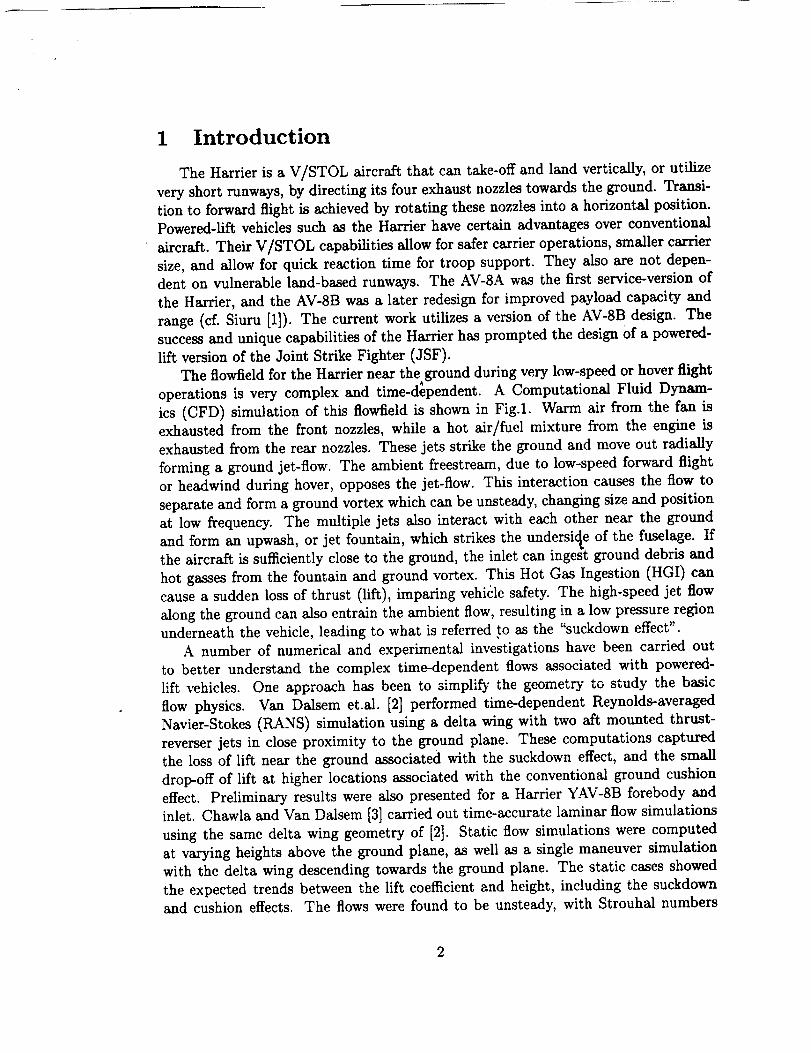
The flowiield for the Harrier near the ground during very low-speed or hover flight• , • _ o °
operations Is very complex and t_ne-dependent. A Computational Flmd Dynam-
ics (CFD) simulation of this flowiield is shown in Fig.1. Warm air from the fan is
exhausted from the front nozzles, while a hot air/fuel mixture from the engine is
exhausted from the rear nozzles. These jets strike the ground and move out radially
forming a ground jet-flow. The ambient freestream, due to low-speed forward flight
or headwind during hover, opposes the jet-flow. This interaction causes the flow to
separate and form a ground vortex which can be unsteady, changing size and position
at low frequency. The multiple jets also interact with each other near the ground
and form an upwash, or jet fountain, which strikes the undersic_e of the fuselage. Ifthe aircraft is sufficiently close to the ground, the inlet can ingest ground debris and
hot gasses from the fountain and ground vortex. This Hot Gas Ingestion (HGI) can
cause a sudden loss of thrust (lift), imparing vehicle safety. The high-speed jet flow
along the ground can also entrain the ambient flow, resulting in a low pressure region
underneath the vehicle, leading to what is referred to as the "suckdown effect".
A number of numerical and experimental investigations have been carried out
to better understand the complex time-dependent flows associated with powered-
lift vehicles. One approach has been to simplify the geometry to study the basic
flow physics. Van Dalsem et.al. [2] performed time-dependent Reynolds-averaged
Navier-Stokes (RANS) simulation using a delta wing with two aft mounted thrust-
reverser jets in close proximity to the ground plane. These computations captured
the loss of lift near the ground associated with the suckdown effect, and the small
drop-off of lift at higher locations associated with the conventional ground cushion
effect. Preliminary results were also presented for a Harrier YAV-8B forebody and
inlet. Chawla and Van Dalsem [3] carried out time-accurate laminar flow simulations
using the same delta wing geometry of [2]. Static flow simulations were computed
at varying heights above the ground plane, as well as a single maneuver simulation
with the delta wing descending towards the ground plane. The static cases showed
the expected trends between the lift coefficient and height, including the suckdown
and cushion effects. The flows were found to be unsteady, with Strouhal numbers
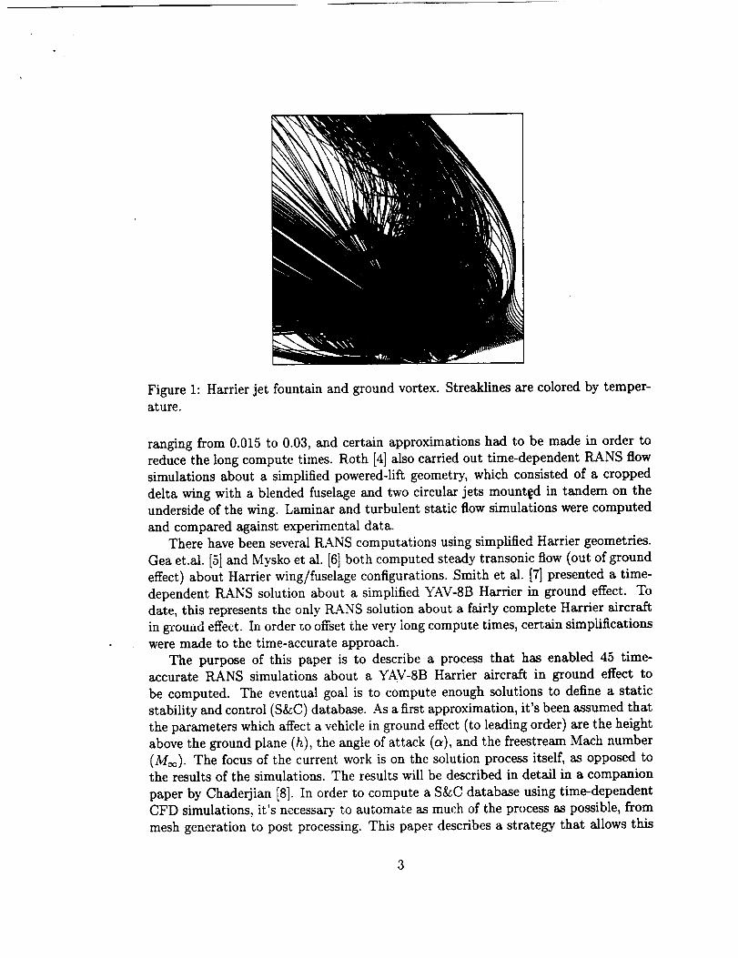
Figure 1: Harrier jet fountain and ground vortex. Streaklines are colored by temper-
ature.
ranging from 0.015 to 0.03, and certain approximations had to be made in order to
reduce the long compute times. Roth [4] also carried out time-dependent RANS flow
simulations about a simplified powered-lift geometry, which consisted of a cropped
delta wing with a blended fuselage and two circular jets mounted in tandem on the
underside of the wing. Laminar and turbulent static flow simulations were computed
and compared against experimental data.
There have been several RANS computations using simplified Harrier geometries.
Gea et.al. [5] and Mysko et al. [6] both computed steady transonic flow (out of ground
effect) about Harrier wing/fuselage configurations. Smith et al. [7] presented a time-
dependent RANS solution about a simplified YAV-8B Harrier in ground effect. To
date, this represents the only RANS solution about a fairly complete Harrier aircraft
in gL-ouud effect. In order to offset the very long compute times, certain simplifications
were made to the time-accurate approach.
The purpose of this paper is to describe a process that has enabled 45 time-accurate RANS simulations about a YAV-SB Harrier aircraft in ground effect to
be computed. The eventual goal is to compute enough solutions to define a static
stability and control (S&C) database. As a first approximation, it's been assumed that
the parameters which affect a vehicle in ground effect (to leading order) are the height
above the ground plane (h), the angle of attack (a), and the freestream Mach number
(M_¢). The focus of the current work is on the solution process itself, as opposed tothe results of the simulations. The results will be described in detail in a companion
paper by Chaderjian [8]. In order to compute a S&C database using time-dependent
CFD simulations, it's necessary to automate as much of the process as possible, from
mesh generation to post processing. This paper describes a strategy that allows this
automation, as wellas stillprovidingthe abilityto easilyextend and customize the
processwithout relyingupon cumbersome softwareor third-partysupport. Another
focusofthe currentwork isthe parallelefficiencyofthe flowsimulationprocess,as an
efficientflowsolverisneccessaryinorder to compute a time-dependent low frequency
flowfield.The efficiencyof the OVERFLOW-MLP solver,and it'sinteractionwith
the runtime environment are examined.
The firstsectiondescribesthe detailsofthe computional mesh that was utilized,
and the automatic generationof configurationsforthe differentheightsand anglesof
attack requiredto fillthe S&C database. Next the efficiencyof the flow solverand
the embarrassinglyparallelsolutionstrategyare described,followedby a description
of the post-processingtools.
2 Computational Mesh
Numerical simulationof the Harrier in ground effectcombines the complex ge-
ometry of a full-aircraftconfiguration,and the complex physicsof a jet in crossflow
impinging on a ground plane. In order to accuratelysimulate thistype of flowfield,
Navier-Stokessimulationsare required to resolvethe viscousjet impingement on the
ground plane,the interactionof the jet and ground vortex "fountain"with the air-
craft,as wellas the featuresof the jetsin crossflowthemselves (cf.Fig.1). An overset
gridstrategy(cf.[9,I01)was chosen due to the complex geometry and complex physics
encountered. Using oversetgridsallowsdifferentregionsofthe flowfield,which require
differentlevelsof physicalmodeling, to be easilyhandled, and Che relevantfeatures
ofthe geometry can be easilymodeled. Firstan overview ofthe computational geom-
etry and oversetgridsystem isprovided,then the detailsof the automation process
requiredto generateseparategridsystems foreach aircraftconfigurationispresented.
2.1 Overset Grid System
The initial definition of the Harrier YAV-8B geometry, was obtained from the
work of Smith et al. [7]. The definition used in [7] did not include several features of
the aircraft, and these were added from the original "lofting-line" data supplied by
the then McDonnell Douglas Aircraft Company. Figure 2 shows the computational
geometry used in the current study. Most of the major components of the aircraft are
modeled, including the wing with leading-edge root extension (LERX), empennage,
engine inletregion,and the two engine exhaust nozzles.The engine exhaust nozzles
are scheduled81 degrees from the aftposition,again followingthe work of Smith et
al.The engine thrustratingused forallcalculationswas "short-liftwet". In addition,
the positivecirculationflapsare alsomodeled in theirfully-deflectedposition.Due to
time constraints,itwas not possibleto model the fuselagegun pod/lift-improvement
devices(LIDS).
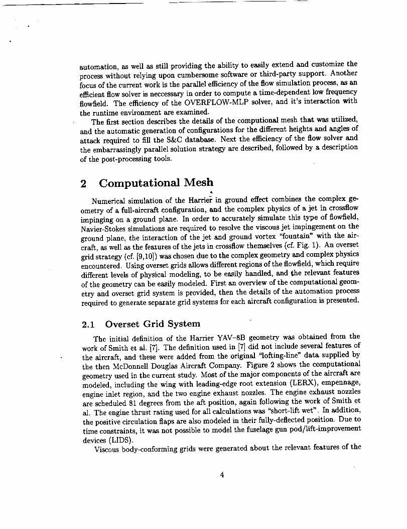
Viscous body-conforming grids were generated about the relevant features of the
4
Figure 2: Computationalgeometryfor Harrier YAV-8B
Figure 3: Harrier oversetsurfacemeshdefinition

v-
V_m-O Vma n V.
/ ,/
(a) (b) (¢)
Figure 4: Aircraft frame of reference transformations including ground plane
Harrier geometry, and the overlapping :§urfaces are shown in Fig. 3. The height of
the first cell above the solid surface was specified such that y+ < 5.0 in each zone,
which was found to be sufficient to resolve the viscous stresses on the surface during
a takeoff or landing scenario. The Reynolds number is 12 million, based on the
aircraft length. An inviscid Cartesian grid, here called the "near-body Cartesian
box", was created to surround the viscous grids with little overlap, and portions
of this Cartesian grid which were interior to the solid surface of the aircraft were
removed using the overset hole-cutting procedure (cf. Fig. 3). This provided a region
surrounding the aircraft which could be placed at any height and orientation relative
to a ground plane, without affecting any of the intergrid connectivity between the
viscous zones. In other words, the viscous zones and near-body Cartesian box could
be processed through the overset connectivity code (Pegasus) once, and then utilized
for every configuration without any changes. All of the surface and volume meshes
were created using the OVERGRID tool for overset grids developed by Chan [11].
The viscous body-conforming grids, along with the fiear-body Cartesian box comprise
45 zones and 2.4 million grid points.
2.2 Process Automation
Simulating the Harrier in ground effect requires proper treatment of the air-
craft/ground plane interaction, which varies from the usual treatment of an aircraft
in flight. Fig. 4 shows the reference frame transformations that can be applied to an
aircraft in ground effect. Figs. 4b and c would be suitable for a numerical simulation
using a fixed grid system, as is used in the current work. Reference frame b) was cho-
sen for this work, so that the flow visualization could take place in a natural frame
of reference.
The viscous body-conforming region was combined with the automated script
system developed for the High Wing Transport [12], in order to develop a system
which could automatically generate the complete system for the aircraft and ground

---L
t
Figure 5: Viscous ground plane and inviscid outer field zones
plane in combination. The script system allowed the processing to be performed
in two steps; first the aircraft was placed at the desired height and orientation and
the viscous intergrid connectivity was established, then the ground plane and farfield
grids were placed around the aircraft, and the complete connectivity was determined.
An example complete grid system is sho_ in Fig. 5. The jet exhaust rc_E,3n was
modeled using viscous Cartesian zones which are generated specifically for each height
and angle of attack. The viscous ground plane is broken into three regions to allow
higher resolution directly under the aircraft where the jet impingement creates large
gradients. The final grid system consists of 52 zones, and 3.6 million grid points for
the configuration with the aircraft at 30 feet above the ground plane. The number
of grid points changes with height, due to the generation of specific grids for the jet
region at each height, as will be discussed below. The system has been validated
by computations and comparisons to the previous computational results of Smith et
al. [7]. These comparisons with previous computational work and other flight-test
data will be included in the complete paper.
In order to avoid generating field grids specifically for each configuration, a general
set of field grids were created and an overset hole-cutting procedure was used to
7
eliminate portions of the grids which weren't necessary, depending upon the aircraft
height. For example, the green inviscid grid in Fig. 5 actually extends above the
aircraft, however that portion is removed by the red grid which surrounds the aircraft
box. Similarly, depending upon the height and angle of attack, the red outer zone and
jet grids may extend below the viscous ground plane, so a cutting plane is established
to remove them if necessary. In this manner, some points aren't utilized due to the
hole cutting procedure, but there is no need to generate separate field grids for each
configuration. The exception to this strategy is the viscous zones which model the jet
convection to the ground plane. These zones are computed using a complete Navier-
Stokes algorithm, as opposed to the thin-layer Navier-Stokes approximation which is
used for the body-conforming viscous zones. Hence these jet grids are both dense and
expensive to compute. Instead of removing portions of the jet grids using an overset
hole-cutting procedure, which would lead to expensive computations essentially being
thrown away due to the iblank logic, these grids were generated specifically for each
height and then rotated into position relative to the aircraft based on the angle ofattack.
The wallclock time required to generate a single overset grid system, including
storing the files on a remote database, was approximately 10 minutes. The processing
system was a 2-CPU desktop workstation, and Pegasus 4.1 [13] was used as the overset
grid processing software.
3 Remote Database Interfacet
Computing an S&C database involves performing a parametric study of the forces
and moments on the aircraft. In this work, the parameters of interest were chosen
to be the height of the vehicle above the ground plane, the angle of attack, and the
freestream Mach number (h, a, and Moo). Working with such a parameter space,
it's desirable to automate as much of the solution, process as possible - from mesh
generation to post-processing of the computed results. This automation speeds the
overall process and minimizes human errors. To this end, a modular script system was
developed that allowed different facets of the solution process co utilize a consistentinterface and set of tools.
This script system was implemented using the Perl language. Perl was chosen
because it is an object-oriented language which encourages the re-use of components,
and it's a powerful interpreted language which can fulfill all of the needs of the script
system without resorting to creating specialized compiled binaries, or mixing script-
ing languages. One of the requirements on the script system for the current work was
to manage a heterogeneous, specialized computing environment. In this environment,
each computer (or group of computers) has a specific dedicated task - one machine
is dedicated to archival storage, one machine is dedicated to high-performance com-
puting, one machine is dedicated to post-processing and flow visualization.
The backbone of the script system is an interface to an S&C database stored on a
8
Remote ]
Single, Static Interfaceto Database
Mesh
Generation
Flow Solver
Run Scripts
Post
Processing
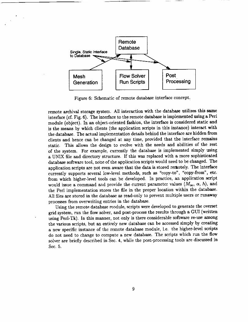
Figure 6: Schematic of remote database interface concept.
remote archival storage system. All interaction with the database utilizes this same
interface (cf. Fig. 6). The interface to the remote database is implemented using a Perl
module (object). In an object-oriented fashion, the interface is considered static and
is the means by which clients (the application scripts in this instance) interact with
the database. The actual implementation details behind the interface are hidden from
clients and hence can be changed at any time, provided that the interface remains
static. This allows the design to evolve with the needs and abilities of the rest
of the system. For example, currently the database is implemented simply using
a UNIX file and directory structure. If this was replaced with a more sophisticated
database software tool, no'he of the application scripts would need to be changed. The
application scripts are not even aware that the data is stored remotely. The interface
currently supports several low-level methods, such as "copy-to", "copy-from", etc.
from which higher-level tools can be developed. In practice, an application script
would issue a command and provide the current parameter values (Moo, a, h), and
the Perl implementation stores the file in the proper location within the database.
All files are stored in the database as read-only to prevent multiple users or runaway
processes from overwriting entries in the database.
Using the remote database module, scripts were developed to generate the overset
grid system, run the flow solver, and post-process the results through a GUI (written
using Perl-Tk). In this manner, not only is there considerable software re-use among
the various scripts, but an entirely new database can be accessed simply by creating
a new specific instance of the remote database module, i.e. the higher-level scripts
do not need to change to compute a new database. The scripts which run the flow
solver are briefly described in Sec. 4, while the post-processing tools are discussed in
Sec. 5.
9

4 Simulation Process
4.1 OVERFLOW-MLP Solver
One of the goals of the current project is to utilize large-scale parallel comput-
ers, such as the NASA Ames 512-processor R12000 SGI Origin 2000 (O2K) machine,
to compute the S&C database. The SGI O2K is a shared-memory, multi-processor
(SMP) machine. A version of the OVERFLOW solver [14], called OVERFLOW-MLP
(for "multi-level parallelism"), has been developed by Taft [15] for use on these typesof architectures. The OVERFLOW-MLP solver utilizes two levels of parallelism -
domain decomposition, and procedural (or loop-level) parallelism. The domain de-
composition scheme is implemented on top of the "production" version of the parallel
OVERFLOW solver.
As the OVERFLOW-MLP solver uses two methods of parallelization, there are
combinations of parameters that can b'e varied to effect performance of the code.
The main parameters are the number of processors per domain (which can vary
from one domain to the next), the number of domains, and the total number of
processors utilized. As a large number of cases are required to fill the S&C database,
some experimentation was performed to determine an optimum configuration of the
OVERFLOW-MLP control parameters for the current problem configuration.
Initially it was found that the OVERFLOW-MLP solver did not provide good a
good load balance when used as a pure domain decomposition parallel solver. This
was caused by the load-balancing routine ignoring the type of scheme used in a
particular overset zone (e.g. inviscid vs. viscous), and simply us_g the total number
of grid points in an overset zone to determine the weighting strategy. In many cases
this strategy is effective, however in the current work the jet grids are both large andcontain the full viscous terms. This makes these grids much more computationally
expensive than the Euler or thin-layer N-S grids,, and hence caused problems for
the simplistic load-balancing algorithm. A weighting based upon the type of scheme
used in each zone was added to the load-balancing algorithm, and this improved
the performance of the pure domain decomposition scheme. Even ._.dth this modest
improvement, the load-balancing algorithm is still not performing as desired, and a
new scheme will likely be developed. The details and performance of this new scheme
will be detailed in the full paper.
Using the OVERFLOW-MLP code essentially as a pure domain-decomposition
scheme (i.e. using 1 CPU per domain), it was efficient to compute using 16 CPUs for
the current Harrier application. This was suitable for computing a database using
the embarrassingly-parallel approach to be discussed in the next section, however
it is still desirable to utilize large numbers of CPUs in order to explore database-
fill methods other than the brute force approach, and for future work simulating
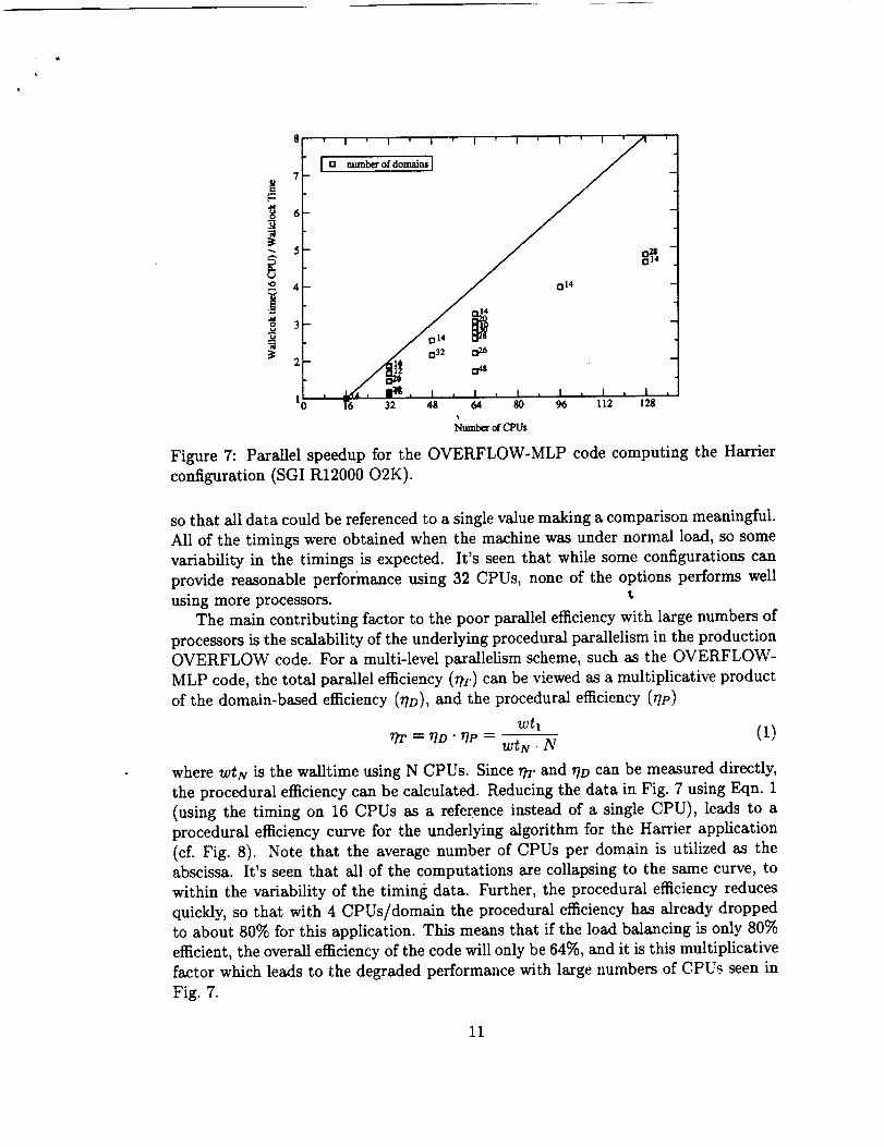
vehicle maneuvers. Figure 7 shows the parallel speedup when computing the Harrier
configuration for 500 physical timesteps: using a variety of domain sizes and CPUs.The ideal time was chosen as the 16 CPU pure domain decomposition configuration,
10
8 ' I ' I ' I _ I ' I ' I ' I _f '/
.
i',o 4 j nl4
7 a3_ 026
. ' ,.L.,_'_, ia_t, I , I , i , I , I , L
1 I"6 32 48 64 80 96 112 128
Number of CPUs
Figure 7: Parallel speedup for the OVERFLOW-MLP code computing the Harrier
configuration (SGI R12000 O2K).
so that all data could be referenced to a single value making a comparison meaningful.
All of the timings were obtained when the machine was under normal load, so some
variability in the timings is expected. It's seen that while some configurations can
provide reasonable performance using 32 CPUs, none of the options performs well
using more processors, t
The main contributing factor to the poor parallel efficiency with large numbers of
processors is the scalability of the underlying procedural parallelism in the production
OVERFLOW code. For a multi-level parallelism scheme, such as the OVERFLOW-
MLP code, the total parallel efficiency (r/T) can be viewed as a multiplicative product
of the domain-based efficiency (?]D), and the procedural efficiency (r/p)
(1)rlT ---- riD " UP -- WiN " N
where WtN is the walltime using N CPUs. Since rtr and r/D can be measured directly,
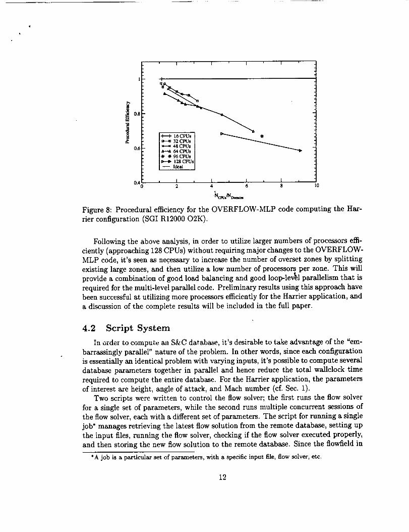
the procedural efficiency can be calculated. Reducing the data in Fig. 7 using Eqn. 1
(using the timing on 16 CPUs as a reference instead of a single CPU), leads to a
procedural efficiency curve for the underlying algorithm for the Harrier application
(cL Fig. 8). Note that the average number of CPUs per domain is utilized as the
abscissa. It's seen that all of the computations are collapsing to the same curve, to
within the variability of the timing data. Further, the procedural efficiency reduces
quickly, so that with 4 CPUs/domain the procedural efficiency has already dropped
to about 80% for this application. This means that if the load balancing is only 80%
efficient, the overall efficiency of the code will only be 64%, and it is this multiplicative
factor which leads to the degraded performance with large numbers of CPUs seen in
Fig. 7.
11
0.8
0.6
' I ' I ' I ' I '
16 CPUs D,,..............._ _
32 CPUs48 CPUs64 CPUs
-_ 96 (:PUs128 CPUs
-- Ideal
i I i I i I a I a0"40 2 4 6 8 lO
-Nc_,/N _
Figure 8: Procedural efficiencyforthe OVERFLOW-MLP code computing the Har-
rierconfiguration(SGI R12000 O2K).
Following the above analysis, in order to utilize larger numbers of processors effi-
ciently (approaching 128 CPUs) without requiring major changes to the OVERFLOW-
MLP code, it's seen as nec.essary to increase the number of overset zones by splitting
existing large zones, and then utilize a low number of processors per zone. This will
provide a combination of good load balancing and good loop-level parallelism that is
required for the multi-level parallel code. Preliminary results using this approach have
been successful at utilizing more processors efficiently for the Harrier application, and
a discussion of the complete results will be included in the full paper.
4.2 Script System
In order to compute an S&C database, it's desirable to take advantage of the "em-
barrassingly parallel" nature of the problem. In other words, since each configuration
is essentially an identical problem with varying inputs, it's possible to compute several
database parameters together in parallel and hence reduce the total wallclock time
required to compute the entire database. For the Harrier application, the parameters
of interest are height, angle of attack, and Mach number (cf. Sec. 1).
Two scripts were written to control the flow solver; the first runs the flow solver
for a single set of parameters, while the second runs multiple concurrent sessions of
the flow solver, each with a different set of parameters. The script for running a single
job* manages retrieving the latest flow solution from the remote database, setting up
the input files, running the flow solver, checking if the flow solver executed properly,
and then storing the new flow solution to the remote database. Since the flowfield in
*A job is a particular set of parameters, with a specific input file, flow solver, etc.
12
t
[ __, ] ,,-,o.,,-7
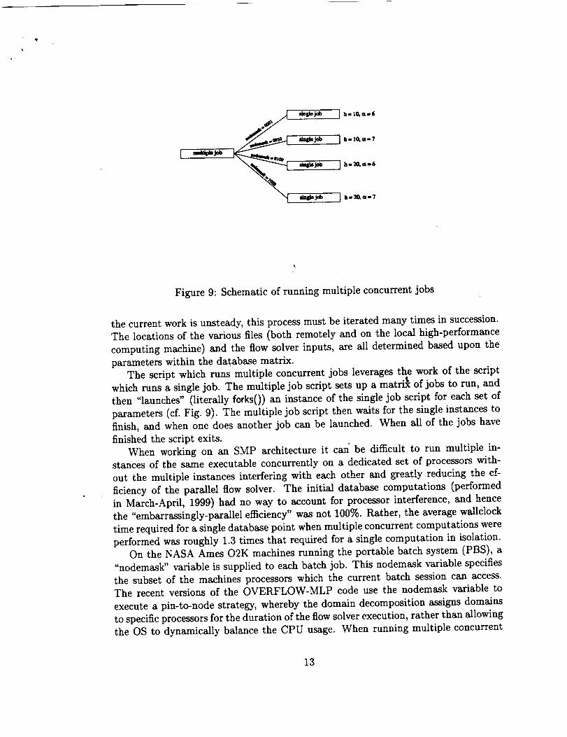
Figure 9: Schematic of running multiple concurrent jobs
the current work is unsteady, this process must be iterated many times in succession.
The locations of the various files (both remotely and on the local high-performance
computing machine) and the iiow solver inputs, are all determined based upon the
parameters within the database matrix.
The script which runs multiple concurrent jobs leverages the work of the script
which runs a single job. The multiple job script sets up a matri_ of jobs to run, and
then "launches" (literally forks()) an instance of the single job script for each set of
parameters (cf. Fig. 9). The multiple job script then waits for the single instances to
finish, and when one does another job can be launched. When all of the jobs have
finished the script exits.
When working on an SMP architecture it can be difficult to run multiple in-
stances of the same executable concurrently on a dedicated set of processors with-
out the multiple instances interfering with each other and greatly reducing the ef-
ficiency of the parallel flow solver. The initial database computations (performed
in March-April, 1999) had no way to account for processor interference, and hence
the "embarrassingly-parallel efficiency" was not 100%. Rather, the average wallclock
time required for a single database point when multiple concurrent computations were
performed was roughly 1.3 times that required for a single computation in isolation.
On the NASA Ames O2K machines running the portable batch system (PBS), a
"nodemask" variable is supplied to each batch job. This nodemask variable specifies
the subset of the machines processors which the current batch session can access.
The recent versions of the OVERFLOW-MLP code use the nodemask variable to
execute a pin-to-node strategy, whereby the domain decomposition assigns domains
to specific processors for the duration of the flow solver execution, rather than allowing
the OS to dynamically balance the CPU usage. When running multiple concurrent
13
versions of the OVERFLOW-MLP executable, it's thus necessary to apply another
mask to the nodemask variable that PBS provides - a so-called "job mask" which
specifies the processors which each specific job should utilize. In other words, if 16
processors are supplied by PBS, and it's desired to run 4 concurrent jobs, the job
mask would mask portions of the original 16 processors so that 4 distinct processors
are available to each job. This was done by creating a Perl module which stores
the original PBS nodemask variable, and then portions it out to each job that is
launched so that no two jobs can access the same processor (cf. Fig. 9). In this
manner, concurrent versions of the same executable can be run without processor
interference, and without requiring modification of the flow solver code. Using the
job nodemask and the pin-to-node strategy, the embarrassingly-parallel efficiency
when running multiple concurrent cases was indistinguishable from the theoreticalmaximum of 100%.
5 Post Processing
As with the mesh generation and flow simulation processes, when analyzing hun-
dreds (or more) of CFD simulations it's desirable to automate much of the post-
processing analysis. This automation can also be used to "mine" the database for
interesting or critical points, as well as obtain general structures. As was discussed
in Sec. 3, a GUI tool was built upon the remote database interface using Perl-Tk and
utilized to perform post-processing analysis of the S&C database.
The GUI tool, referred to as "DBview", has two main modes _f operation; interac-
tive and batch processing. In interactive mode DBview is itself in some sense simply
a layer between the remote database and analysis application software residing on
the engineers desktop machine. For example, DBview does not provide any graphical
plotting capability, rather it retrieves the relevant data from the remote database and
calls a third-party graphical application to display and analyze the results. In batch
processing mode, a number of database entries can be selected to have certain tasks
performed (with the results to be stored in the remote database), and the DBview
tool again simply manages the data movement and choosing the proper application
to run. With this approach, the GUI tool is both open-ended, since new third-party
applications can simply be added as necessary, and lightweight, as the GUI simply
must manage user input and data movement without needing to perform complicated
or specialized analysis tasks.
The DBview "front-end" is shown in Fig. 10. Access tabs for choosing the desired
database are in the upper left of the interface. In this example, the two possible
databases are "Baseline" and "SNC01". The parameters shown in the selection area
below the tabs change to those appropriate for the chosen database. Once the pa-
rameters are selected, the user can choose one or more of the check-buttons on the
top right side of Fig. 10 to interrogate the grid and solution, or to view the load
histories. Selecting the "grid" or "solution" check-button and pressing the "Get and
14

t
r,
Figure 10: Database post-processing graphical user interface.
Plot File" button results in the retrieval of the appropriate files from the database
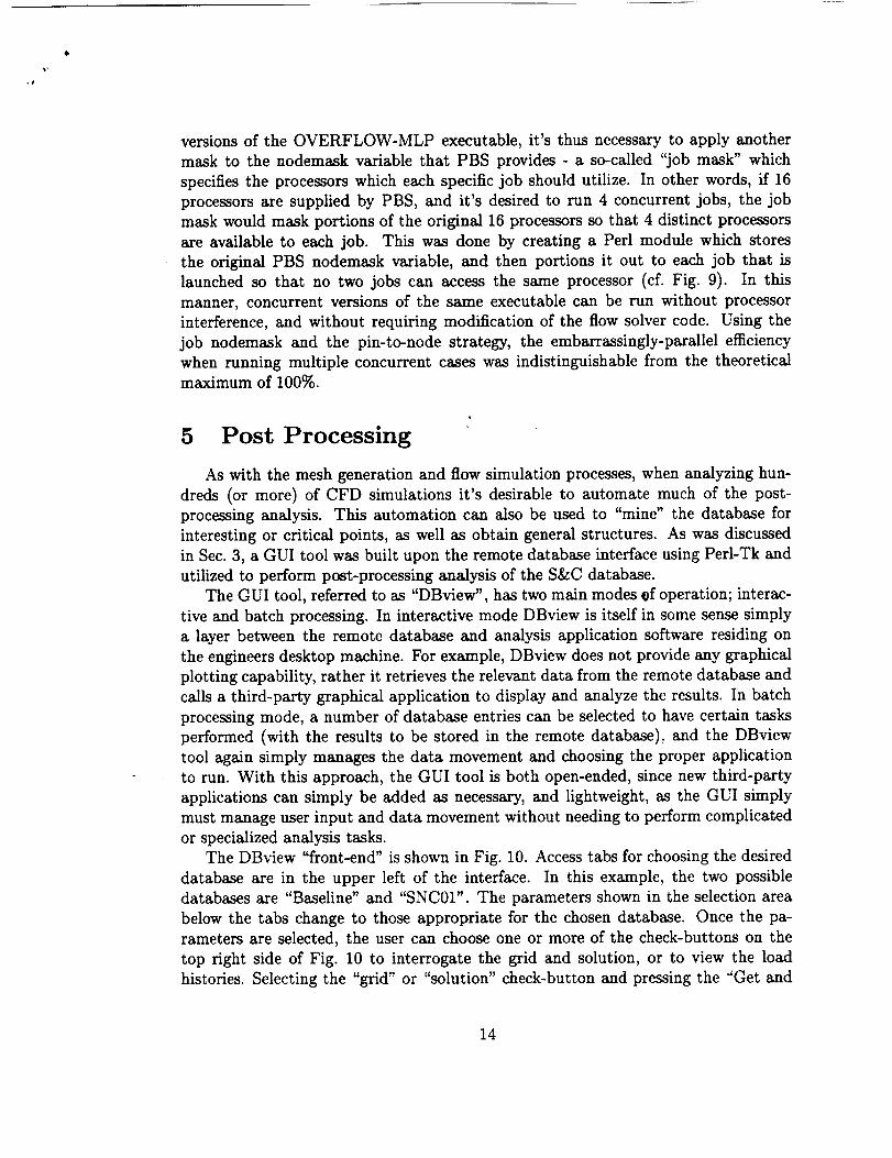
followed by an interactive flow visualization session To aid the analysis, pre-loaded•
flowfield visualizations are available, and can either be printed to hardcopy or stored
in the remote database. An example of this "thumbnail" analysis is shown in Fig. 11.
The GUI tool can take arbitrary slices through the data, including constant planes,
vectors, or arbitrary isolated points in the database. The main interactive features
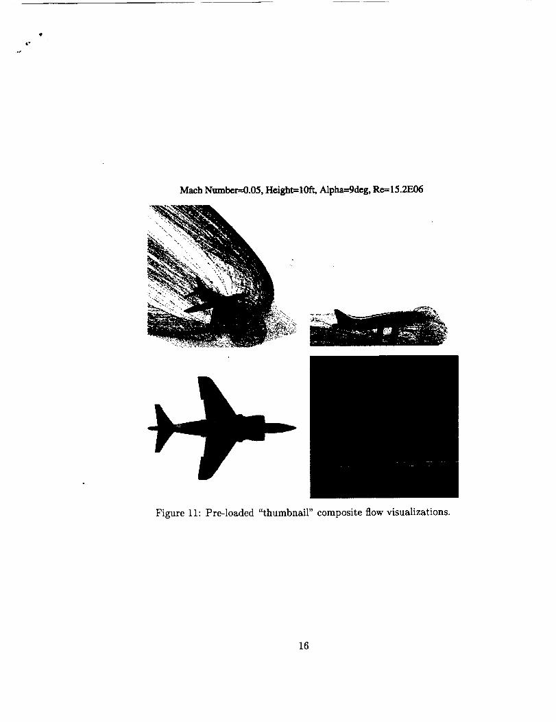
of the tool axe graphical plotting of the load histories*, and 3-D visualization tools.
An example of the load history post-processing is shown in Fig. 12. Arbitrary entries
in the database can be selected and are automatically retrieved from the remote
database and plotted in a third-party application. The labels and legends are also
automatically generated.
6 Summary
A method of automating the generation of a time-dependent, Navier-Stokes static
S&C database for the Harrier aircraft in ground effect has been outlined. Lightweight
reusable components were created which allowed different facets of the CFD simula-
tion process to utilize a consistent interface to a remote database. These components
*All of the computed solutions are time-dependent, hence the time-history of the load variation
must be plotted, not just a steady-state value.
15
@
.o,
Mach Number--0.05, Height=10ft, Alpha---gdcg, R_ 15.2E06
• . • . _ • -:_,_.
Figure 11: Pre-loaded "thumbnail" composite flow visualizations.
16
Lift History
0
-0.25
-0.5
-0.75
-10 4 8 12
Physical Time(seconds)
Figure 12: Example of post-processing time-dependent load histories.
also allowed changes and customizations to easily be facilitated into the solution pro-
cess to enhance performance without relying upon third-party support. An analysis
of the multi-level parallel solver OVERFLOW-MLP was presemted, and the results
indicate that it is feasible to utilize large numbers of processors (_ 100) even with a
grid system with relatively small number of cells (_ 106). The full paper will include
a more detailed discussion of the simulation process, as well as refined data for the
scaling of the OVERFLOW-MLP flow solver.
References
[1]
[2]
[3]
[4]
Siuru, W. D., British Aerospace and McDonnell Douglas Harrier A V-8A/B. Aero
Publishers, Inc., 1985.
Van Dalsem, W. R., Chawla, K., Smith, M. H., and Abeloff, P. A., "Numerical
Simulation of Powered-Lift Flows," in International Powered LiB Conference
Proceedings, pp. III.16.1-14, The Royal Aeronautical Society, 1990.
Chawla, K., and Van Dalsem, W. R., "Numerical Simulation of a Powered-Lift
Landing," AGARD-CP 534, 1993.
Roth, K. R., "Comparison of Computation with Experiment for a Geometri-
cally Simplified Powered-Lift Model," AIAA Journal of Aircraft, vol. 34, no. 2,
pp. 160-167, 1997.
17

,t
J
[5]
[6]
[7]
[8]
[9]
[10]
[11]
[12]
[13]
[14]
[15]
Gea, L. M., Chyu, W. J., Stortz, M. W., Roberts, A. C., and Chow, C. Y., "FlightTest and Numerical Simulation of Transonic Flow Around YAV-SB Harrier II
Wing," AIAA Paper 91-!628, 1991.
Mysko, S. J., Chyu, W. J., Stortz, M. W., and Chow, C. Y., "Navier-Stokes
Simulation of External/Internal Transonic Flow on the Forebody/Inlet of the
AV-SB Harrier II," AIAA Paper 93-3057, 1993.
Smith, M.H., Chawla, K., and Van Dalsem, W. R., "Numerical Simulation of
a Complete STOVL Aircraft in Ground Effect," AIAA Paper 91-3293-CP, July1991.
Chaderjian, N.M., Pandya, S., Murman, S.M., and Ahmad, J., "Parametric
Time-Dependent Navier-Stokes Computations for a YAV-8B Harrier in Ground
Effect," submitted for publication at AIAA 40th Aerospace Sciences Meeting.
Benek, J.A., Buning, P.G., and Steger, J.L., "A 3-D Chimera Grid Embedding
Technique," AIAA Paper 85-1523, July 1985.
Buning, P.G., Chiu, I.T., Obayashi, S., Pdzk, Y.M. and Steger, J.L., "Numerical
Simulation of the Integrated Space Shuttle Vehicle in Ascent," AIAA Paper 88-
4359-CP, Aug. 1988.
Chan, W.M., Meakin, R.L., and Potsdam, M.P., "CHSSI Software for Geomet-
rically Complex Unsteady Aerodynamic Applications," AI/_:A Paper 2001-0593,Jan. 2001.
Rogers, S. E., Roth, K., Nash, S. M., Baker, M. D., Slotnick, J. P., Whitlock,
M., and Cao, H. V., "Advances in Overset CFD Processes Applied to Subsonic
High-Lift Aircraft," AIAA Paper 2000-4216, Aug. 2000.
Suhs, N.E. and Tramel, R.W., "Pegsus 4.0 User's Manual," AEDC Tech. Report
TR-91-8, 1991.
Buning, P.G., Jesperson, D.C., Pulliam, T.H., Chan, W.M., Slotnick, J.P., Krist,
S. E., and Renze, K.J., OVERFLOW User's Manual. NASA.
Taft, J.R., "Multi-Level Parallelism, A Simple Highly Scalable Approach to Par-
allelism for CFD," in HPCCP/CAS Workshop 98 Proceedings (C. Schulbach,
ed.), 1998.
18