automation of gating system parameters for green sand iron ... · c = efficiency factor which is a...
TRANSCRIPT

Journal of Advances in Mathematics and Computer Science 27(6): 1-15, 2018; Article no.JAMCS.28497
ISSN: 2456-9968 (Past name: British Journal of Mathematics & Computer Science, Past ISSN: 2231-0851)
_____________________________________
*Corresponding author: E-mail: [email protected], [email protected];
Automation of Gating System Parameters for Green Sand Iron Castings
M. D. Shittu1*, S. A. Ibitoye1, P. O. Atanda1, J. O. Olawale1, K. M. Oluwasegun1
and O. O. Ige1
1Department of Materials Science and Engineering, Obafemi Awolowo University, Ile-Ife, Nigeria.
Authors’ contributions
This work was carried out in collaboration between all authors. Author MDS designed the study, generated the codes in MATLAB and developed the Guided Users’ Interfaces (GUIs). Authors MDS, POA and JOO
carried out the validation and evaluation of the work at the foundry shop and Laboratories of the Department of Materials Science and Engineering, Obafemi Awolowo University, Ile-Ife, Nigeria. Author
MDS coordinated the preparation of the manuscript with authors KMO and OOI while author SAI reviewed and corrected the manuscript. All authors read and approved the final manuscript.
Article Information
DOI: 10.9734/JAMCS/2018/28497
Editor(s): (1) Junjie Chen, Professor, Department of Electrical Engineering, University of Texas at Arlington, USA.
Reviewers: (1) Hao Wang, Northeastern University, China.
(2) Sie Long Kek, Universiti Tun Hussein Onn Malaysia, Malaysia. Complete Peer review History: http://www.sciencedomain.org/review-history/25253
Received: 12th July 2016 Accepted: 20th September 2016
Published: 25th June 2018
_______________________________________________________________________________
Abstract
This paper developed a simple but accurate automation tool for quick design of gating and riser systems for green sand iron castings. Codes for calculation of gating elements’ parameters were generated in MATLAB from standard fluid mechanics and empirical formulae. Guided Users’ Interfaces (GUIs) were developed to guide the users in the use of the tool. The package was validated with shop floor trials using the tool developed to generate and design gating and riser systems for some grey iron components. These components were moulded in green sand, cast and evaluated using visual inspection, bulk density and apparent porosity measurement and ultrasonic flaw detection methods. The results of evaluation revealed castings free from any form of gating related defects.
Keywords: Rigging system; riser; MATLAB codes; green sand; Guided User Interface.
Original Research Article

Shittu et al.; JAMCS, 27(6): 1-15, 2018; Article no.JAMCS.28497
2
1 Introduction The demand for different cast components increases daily as a result of increase in their applications in various fields such as automobiles, machine tool structures, tractors, aeronautics, atomic energy, defense, and many others. Casting is a very economical process of producing parts and to obtain complicated shapes with little or no machining [1]. This increasing demand for castings poses challenges in term of stringent requirements for quality, for which new technology and methods have to be developed. A more efficient and error free method is needed to increase the production rate and keep material wastage and unproductive efforts at minimum [2].
In the production of defect-free castings, the importance of rigging (gates and risers) system design, channels through which molten metal flows into and fill the mould cavity [3], cannot be overemphasized. It was established that the formation of various casting defects could be directly related to fluid flow phenomena involved in the stage of mould filling [4,5,6,7,8,9,10,11]. There are various known standard methods for designing good gates and risers but the difficulties are in the time spent on calculations of appropriate gating and riser elements. A survey of American Foundries Association conducted in 1996 revealed that nearly 70% of the time between confirmation of order and the production of a good casting sample is consumed by pattern development (including gating and risering system), methodology approval and casting trials [11] In the developing countries, the practice of jobbing foundries is prevalent [12] and this requires a lot of different gating system calculations as there are different castings that have to be produced in small quantities daily. This makes the job of design engineers strenuous and prone to errors. Therefore, there is the need to evolve a working tool to perform the rigging design job faster for more accurate output.
Some remarkable attempts have been made towards automating the design of rigging (gates and risers) system design in die casting processes with only very few for sand casting process. Among the few ones for sand casting process include the EASYCAST [13], computer based simulation for the design of gates and risers [14]. Other well established but expensive packages such as SOLIDcast, CastDesigner, Novocast etc are all software packages that are effectively useful in production foundries for grey iron, ductile iron, etc. in green sand, investment casting and permanent mould but they are rather very expensive for foundry jobbers.
As a result, this work developed a simple simulation tool to perform the job of gating calculations. This paper give the step by step process for determination of gating system parameters from some designed Guided Users Interfaces (GUIs) prepared in MATLAB for a greensand system for production of grey iron castings. In the work, the various gating system parameters were calculated using theoretical concepts and casting rules, which basically are fluid mechanics and empirical rules. The interest on sand casting is borne on certain advantages it has over other casting processes. Among these advantages are that almost any metal can be cast, no limit on size and shape, low equipment cost and very economical for low volume production [15].
2 Materials and Methods The equipments used for this work were oil-fired crucible furnace, spring balance, lathe machine and Sonatest ultrasonic testing machine Model 250S. The materials used were grey iron scraps, ferrosilicon, carburizer, silica sand, clay, wooden moulding boxes, and wood for the pattern makings.
In this work, the major experimental procedure includes generation of computer codes (using MATLAB) to perform gating and riser systems calculations from empirical rules and general fluid mechanics, designing of Guided User Interfaces (GUIs), and validation of the codes and GUIs through pattern making, designing and making of gating and risers elements (Fig. 1), moulding and casting of components in greensand and evaluation of the cast components.

Shittu et al.; JAMCS, 27(6): 1-15, 2018; Article no.JAMCS.28497
3
Fig. 1. Elements of a gating system (Rao, 2001)
2.1 Generation of codes
Here the standard and accepted empirical formulae and fluid mechanics rules for calculating gating systems were coded in MATLAB. Some of the formulae and rules used are as presented in Equation (2.1) to Equation (2.9).
2.1.1 Determination of pouring time, t.
The pouring time depends on the casting materials, complexity of the casting, section thickness and casting size. It is determined by using some standard methods of calculating the pouring time for different sizes of cast iron [16] as reported by [17,18] thus:
(a) Mass less than 450 kg (i.e. W < 450 kg)
WT
kt
59.1441.1 (2.1)
(b) For W 450 kg
3
65.16236.1 W
Tkt
(2.2)
where k is the fluidity constant which depend on metal composition factor, pouring temperature, metal viscosity, and rate of heat transfer.
T = average section thickness of the casting in mm
t = pouring time in seconds
W= poured weight which is the casting weight plus the weight of gating elements including risers in kg

Shittu et al.; JAMCS, 27(6): 1-15, 2018; Article no.JAMCS.28497
4
2.1.2 Calculating choke area This is the main control area which regulates the metal flow into the mould cavity so that the mould is completely filled within the calculated pouring time. This is at the bottom of the sprue in a non pressurized gate while it is located at the tip of the ingates in a pressurized gating system [19]. The choke area, Ac can be calculated using Bernoulli’s equation as
gHtC
WAc
2 (2.3)
where
Ac = Choke area, mm2
= Mass density of molten metal, kg/mm3. For grey cast iron, = 6.09 x 10⁻⁶, kgmm-3 [20]
g = acceleration due to gravity (9810 mms-2)
H = effective metal head (sprue height), mm
C = Efficiency factor which is a function of the gating system used (between 0.7 to 0.9) 2.1.3 Determining other dimensions of the sprue The sprues were tapered down to take into account the gain in velocity of the metal as it flows down reducing the air aspiration [1]. The exact tapering was obtained by Bernoulli’s continuity expression (Equation 2.4). Denoting the top and choke sections of the sprue by subscripts t and c respectively, then
t
cct
h
hAA (2.4)
where
At = Top cross sectional area of the sprue
Ac = Choke area of the sprue
ht = Height of the sprue
hc = Height of the sprue 2.1.4 Determining dimensions for other gating elements 2.1.4.1 Pouring basin Experience shows that the pouring basin depth of 2.5 times the sprue entrance diameter is enough for smooth metal flow and to prevent vortex formation. This value was used to design the pouring basin [17]. 2.1.4.2 Sprue base well The sprue base well area of five times that of the sprue choke area and the well depth of approximately equal to that of the runner [1,21]. For a narrow and deep runner the well diameter should be 2.5 times the width of the runner in a two-runner system and twice its width in a one-runner system [17].
Shittu et al.; JAMCS, 27(6): 1-15, 2018; Article no.JAMCS.28497
5
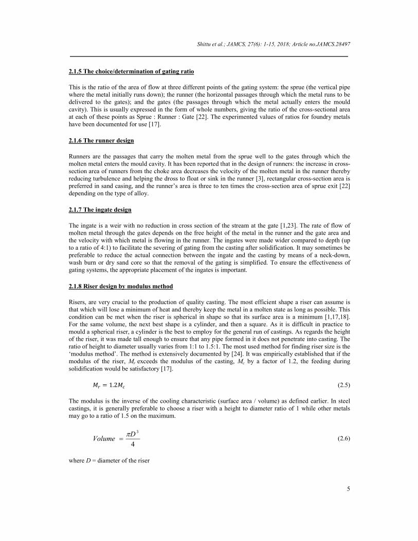
2.1.5 The choice/determination of gating ratio This is the ratio of the area of flow at three different points of the gating system: the sprue (the vertical pipe where the metal initially runs down); the runner (the horizontal passages through which the metal runs to be delivered to the gates); and the gates (the passages through which the metal actually enters the mould cavity). This is usually expressed in the form of whole numbers, giving the ratio of the cross-sectional area at each of these points as Sprue : Runner : Gate [22]. The experimented values of ratios for foundry metals have been documented for use [17].
2.1.6 The runner design
Runners are the passages that carry the molten metal from the sprue well to the gates through which the molten metal enters the mould cavity. It has been reported that in the design of runners: the increase in cross-section area of runners from the choke area decreases the velocity of the molten metal in the runner thereby reducing turbulence and helping the dross to float or sink in the runner [3], rectangular cross-section area is preferred in sand casing, and the runner’s area is three to ten times the cross-section area of sprue exit [22] depending on the type of alloy.
2.1.7 The ingate design
The ingate is a weir with no reduction in cross section of the stream at the gate [1,23]. The rate of flow of molten metal through the gates depends on the free height of the metal in the runner and the gate area and the velocity with which metal is flowing in the runner. The ingates were made wider compared to depth (up to a ratio of 4:1) to facilitate the severing of gating from the casting after solidification. It may sometimes be preferable to reduce the actual connection between the ingate and the casting by means of a neck-down, wash burn or dry sand core so that the removal of the gating is simplified. To ensure the effectiveness of gating systems, the appropriate placement of the ingates is important.
2.1.8 Riser design by modulus method
Risers, are very crucial to the production of quality casting. The most efficient shape a riser can assume is that which will lose a minimum of heat and thereby keep the metal in a molten state as long as possible. This condition can be met when the riser is spherical in shape so that its surface area is a minimum [1,17,18]. For the same volume, the next best shape is a cylinder, and then a square. As it is difficult in practice to mould a spherical riser, a cylinder is the best to employ for the general run of castings. As regards the height of the riser, it was made tall enough to ensure that any pipe formed in it does not penetrate into casting. The ratio of height to diameter usually varies from 1:1 to 1.5:1. The most used method for finding riser size is the ‘modulus method’. The method is extensively documented by [24]. It was empirically established that if the modulus of the riser, Mr exceeds the modulus of the casting, Mc by a factor of 1.2, the feeding during solidification would be satisfactory [17].
�� = 1.2�� (2.5)
The modulus is the inverse of the cooling characteristic (surface area / volume) as defined earlier. In steel castings, it is generally preferable to choose a riser with a height to diameter ratio of 1 while other metals may go to a ratio of 1.5 on the maximum.
4
3DVolume
(2.6)
where D = diameter of the riser

Shittu et al.; JAMCS, 27(6): 1-15, 2018; Article no.JAMCS.28497
6
The bottom end of the riser is in contact with the casting and does not contribute to the calculation of surface area.
Surface area = 22
4D
D
(2.7)
The modulus of such a cylindrical riser, Mr would be
Mr = 0.2Dr (2.8) Since Mr = 1.2 Mc
Dr = 6 Mc (2.9)
where Mc = Modulus of the casting
2.2 Validation and evaluation of the developed package Each of the patterns was moulded with different placement (top, parting line and bottom gating) of gating systems in green sand moulding. Charge calculation was made for the grey cast iron. Thereafter, the iron charge was melted in crucible melting furnace, poured into already prepared sand moulds and cast to respective plates, gear blanks and rod of the earlier indicated dimensions. They were allowed to solidify and cool in the sand to the ambient temperature, shook-out of the sand and fettled. After proper cleaning, the cast components were visually inspected for the presence of casting defects such as cold shut (misrun, cold lap), hot tears, slag holes, blowholes, shrinkage, pin holes and ceroxides which are visually obvious and observable using hand held lens. Each of the cast components was lightly skinned by machining off about 2 mm all around it for better dimensional measurement, weighed using a sensitive spring balance and the weight, wa read and recorded. The sample was then lowered inside water of density D, and its weight, wb
noted and recorded which according to Achimedes Principle equals to the weight of water displaced. Precaution was taken to ensure that the sample did not rest on the side or bottom of the can while weighing. Finally, the soaked metal was gently removed from the water and while suspending in air, the weight, wc was noted and recorded. The bulk density, Db and apparent porosity, Pa of each cast component were then evaluated using Equation (2.10) and Equation (2.11) respectively
bc
ab
WW
DWD
* (2.10)
ba
aca
WW
WWP
(2.11)
where Wc > Wb and Wa > Wb The results obtained were then compared with the ASTM (American Standards for Testing Metals) Standard of grey cast iron. In this research the density of water used was taken as 1 gcm-3 (i.e. 1000 kgm-3). To ensure the internal integrity of the casting, an electronic oscillator, Model 250S was used to send out alternating current to piezoelectric transducer that converted the electric energy to acoustic energy of same frequency 4.0 MHz used in this study. Having calibrated the machine with the standard samples V1 and V2 blocks in succession, the acoustic energy was sent to the skinned (lightly machined) cast sample using light grease as couplant to ease the probe movement by reducing the friction between the probe and workpiece. The movements of the acoustic waves (transmitted and returning) were displayed on the cathode ray oscillograph (CRO) screen and captured using a digital camera. This exercise was with a view to establish the presence of internal defects in the castings.
Shittu et al.; JAMCS, 27(6): 1-15, 2018; Article no.JAMCS.28497
7
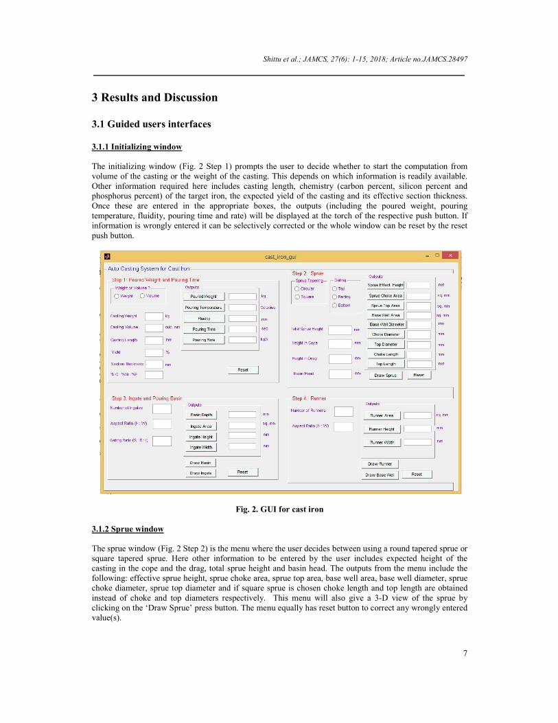
3 Results and Discussion 3.1 Guided users interfaces 3.1.1 Initializing window The initializing window (Fig. 2 Step 1) prompts the user to decide whether to start the computation from volume of the casting or the weight of the casting. This depends on which information is readily available. Other information required here includes casting length, chemistry (carbon percent, silicon percent and phosphorus percent) of the target iron, the expected yield of the casting and its effective section thickness. Once these are entered in the appropriate boxes, the outputs (including the poured weight, pouring temperature, fluidity, pouring time and rate) will be displayed at the torch of the respective push button. If information is wrongly entered it can be selectively corrected or the whole window can be reset by the reset push button.
Fig. 2. GUI for cast iron
3.1.2 Sprue window The sprue window (Fig. 2 Step 2) is the menu where the user decides between using a round tapered sprue or square tapered sprue. Here other information to be entered by the user includes expected height of the casting in the cope and the drag, total sprue height and basin head. The outputs from the menu include the following: effective sprue height, sprue choke area, sprue top area, base well area, base well diameter, sprue choke diameter, sprue top diameter and if square sprue is chosen choke length and top length are obtained instead of choke and top diameters respectively. This menu will also give a 3-D view of the sprue by clicking on the ‘Draw Sprue’ press button. The menu equally has reset button to correct any wrongly entered value(s).
Shittu et al.; JAMCS, 27(6): 1-15, 2018; Article no.JAMCS.28497
8
3.1.3 Ingate and pouring basin window Fig. 2 Step 3 is the ‘Ingate and Pouring Basin’ window by which the user specifies the number of ingates (inner gates) to be used and selects the ‘aspect ratio’ (the ratio of the height to width) of the gates. The gating ratio, is the ratio of the cross sectional area of the choke to sectional area of the runner to sectional area of the ingates, that is, Achoke: Arunner: Aingate. The outputs here include ingate cross sectional area, ingate height, ingate width and basin depth. It also can draw the 3-D views of the basin and the ingate by pressing the ‘Draw Basin’ button and ‘Draw Ingate’ button respectively. It equally has button to reset any wrongly entered data. 3.1.4 Runner and base well window The Runner and base well window (Fig. 2 Step 4) prompts the user to indicate the number of runner to be used (single or double runner i.e. 1 or 2). The other information required in this step is the ‘aspect ratio’ of the runner. The outputs of the menu include runner area, runner height and runner width.
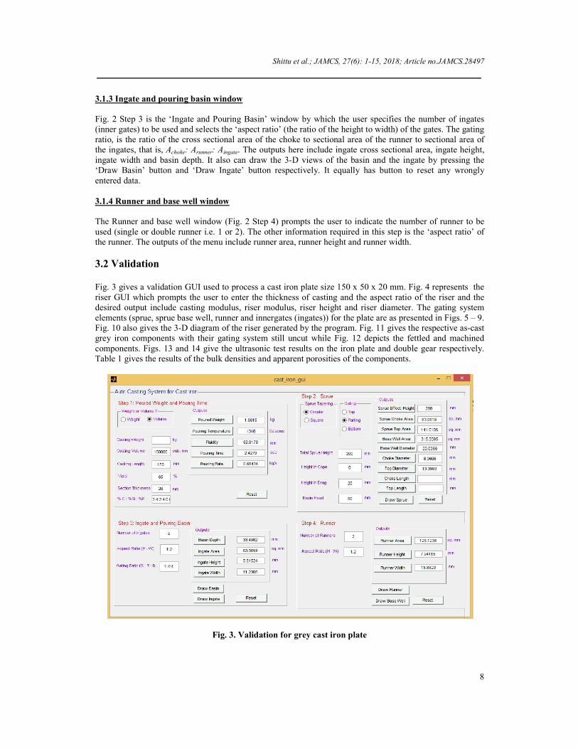
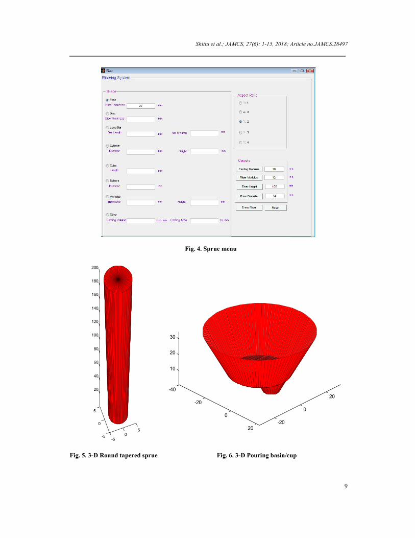
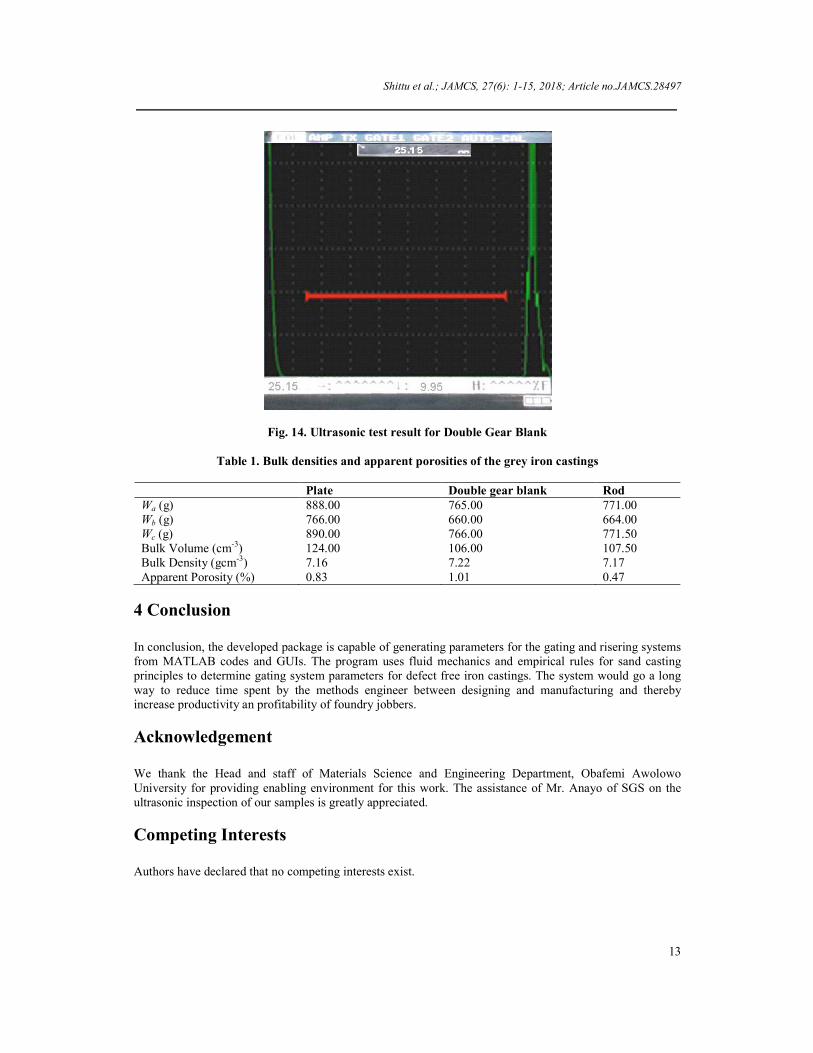
3.2 Validation Fig. 3 gives a validation GUI used to process a cast iron plate size 150 x 50 x 20 mm. Fig. 4 represents the riser GUI which prompts the user to enter the thickness of casting and the aspect ratio of the riser and the desired output include casting modulus, riser modulus, riser height and riser diameter. The gating system elements (sprue, sprue base well, runner and innergates (ingates)) for the plate are as presented in Figs. 5 – 9. Fig. 10 also gives the 3-D diagram of the riser generated by the program. Fig. 11 gives the respective as-cast grey iron components with their gating system still uncut while Fig. 12 depicts the fettled and machined components. Figs. 13 and 14 give the ultrasonic test results on the iron plate and double gear respectively. Table 1 gives the results of the bulk densities and apparent porosities of the components.
Fig. 3. Validation for grey cast iron plate
Shittu et al.; JAMCS, 27(6): 1-15, 2018; Article no.JAMCS.28497
9
Fig. 4. Sprue menu
Fig. 5. 3-D Round tapered sprue Fig. 6. 3-D Pouring basin/cup
-50
5
-5
0
5
20
40
60
80
100
120
140
160
180
200
-40
-20
0
20-20
0
20
10
20
30

Shittu et al.; JAMCS, 27(6): 1-15, 2018; Article no.JAMCS.28497
10
Fig. 7. 3-D Ingate/Inner gate
Fig. 8. 3-D The runner bar From Table 1, the average bulk density and average apparent porosity of the grey iron castings were 7.2 gcm-3 and 0.76% respectively which are in agreement with the ones for grey cast iron from the literature [25]. From Figs. 13 and 14, the pulses from different location on the length of the castings are reflected from the lower surface of the test samples. In a satisfactory metallic material, the pulse passes from the probe unimpeded through the metal and be reflected from the lower inside surface back to the probe, then acting as receiver. Both transmitted pulse and echo are recorded on the CRT (cathode-ray tube), and the distance, d, between peaks is proportional to the thickness,T, of the test piece [25,26,27,28]. Any discontinuity such as
-5
0
5
5
10
15
-2
0
2
-50 5
20
40
60
80
100
120
140
-202
2 0 -2

Shittu et al.; JAMCS, 27(6): 1-15, 2018; Article no.JAMCS.28497
11
blowhole, then the pulse would be interrupted and the echo returns to the receiver in a shorter time an intermediate peak appears on the CRT trace. Based on these assertions and the behavior of the patterns of the peaks of the samples on the CRT at the velocities and frequencies employed, it is clear that the castings are devoid of any gating related defects and therefore are of good quality and likely will have better mechanical properties [29,30,31]. The development of this software is to semi automate the work of the foundry method engineer and it made use of simple and established fluid flow and empirical equations with interface and no need to memorize any commands whereas most of the existing software, though they are integrated, were made from complex formula that cannot be easily explained by the developers. From the time of inputting the necessary information to the point of displaying results, the time spent using the developed tool was approximately 5 minutes (300 seconds) whereas performing the same operation by manual calculation takes about 2 hours (7200 seconds). The package developed is considered to be very easy to use by both technical and non-technical personnel because the GUIs are made to be very simple and very interactive whereas most of the foreign packages are complex and requires expert foundry personnel to run.
Fig. 9. 3-D Sprue base well
Fig. 10. 3-D Riser design
-20
-100
10
20
-20
-10
0
10
200
2
4
6
8
10
-40
-200
20
40
-40
-20
0
20
400
20
40
60
80
100
120

Shittu et al.; JAMCS, 27(6): 1-15, 2018; Article no.JAMCS.28497
12
Fig. 11. As-cast components in grey cast iron
Fig. 12. Slightly machined grey cast iron components
Fig. 13. Ultrasonic test result for plate
Shittu et al.; JAMCS, 27(6): 1-15, 2018; Article no.JAMCS.28497
13
Fig. 14. Ultrasonic test result for Double Gear Blank
Table 1. Bulk densities and apparent porosities of the grey iron castings
Plate Double gear blank Rod Wa (g) 888.00 765.00 771.00 Wb (g) 766.00 660.00 664.00 Wc (g) 890.00 766.00 771.50 Bulk Volume (cm-3) 124.00 106.00 107.50 Bulk Density (gcm-3) 7.16 7.22 7.17 Apparent Porosity (%) 0.83 1.01 0.47
4 Conclusion In conclusion, the developed package is capable of generating parameters for the gating and risering systems from MATLAB codes and GUIs. The program uses fluid mechanics and empirical rules for sand casting principles to determine gating system parameters for defect free iron castings. The system would go a long way to reduce time spent by the methods engineer between designing and manufacturing and thereby increase productivity an profitability of foundry jobbers.
Acknowledgement We thank the Head and staff of Materials Science and Engineering Department, Obafemi Awolowo University for providing enabling environment for this work. The assistance of Mr. Anayo of SGS on the ultrasonic inspection of our samples is greatly appreciated.
Competing Interests Authors have declared that no competing interests exist.

Shittu et al.; JAMCS, 27(6): 1-15, 2018; Article no.JAMCS.28497
14
References [1] Guleyupoglu S. Casting process design guidelines. AFS Transactions. 1997;105:869-876. [2] Parker PP. “Encyclopedia of Engineering”, Hardcover edition, McGraw Hill Book Company Limited,
London; 1993. [3] Srinivasn NK. Foundry Engineering, First Edition, Coimbotore; 1986. [4] Runyoro J, Boutorabi SMA, Campbell J. Critical gate velocity for film forming casting alloys, a basis
for process specification. AFS Transactions. 1992;100:225-234. [5] Campbell J. The ten castings rules guidelines for the reliable production of reliable castings: A draft
process specification. Materials Solutions Conf. on Aluminum Casting Technology, Chicago. 1998; 3-19.
[6] Hu BH, Tong KK, Niu XP, Pinwill I. Design and optimization of runner and gating systems for the
die casting of thin-walled magnesium telecommunication parts through numerical simulation. ELSEVIER: Journal of Materials Processing Technology. 2002;105:128-133.
[7] Esparza CE, Guerrero-Mata MP, Rios-Mercado RZ. Optimal design of gating systems by gradient
search methods. Computational Materials Science. 2006;36(4):457-467. [8] Masuomi M. Effect of gating design on mould filling. International Journal of Cast Metal Research,
American Foundry Society; 2007. [9] Anjo V, Khan R. Gating system design for casting thin Aluminium Alloy (Al-Si) plates. Leonardo
Electronic Journal of Practices and Technologies. 2013;12(23):51-62. [10] Ambekar SA, Jaju SB. A review on optimization of gating system for reducing defect. International
Journal of Engineering Research and General Science. 2014;2(1):93-98. [11] Shukri MI, Elbasheer AM. An expert system for dsigning gates and risers for small and medium size
castings. Sudan Engineering Society Journal. 2015;52(46):39–47. [12] Atanda PO, Olawale JO, Shittu MD, Afonja AA. Current status of iron founding in Nigeria.
Proceedings of Conference of the Faculty of Technology, Obafemi Awolowo University, Ile-Ife, Nigeria; 2012.
[13] Adejuyigbe SB. Computer aided manufacturing of sand casting products. Journal of Engineering and
Applied Sciences. 2007;2(8):1240-1250. [14] Knight B, Cowell DF, Preddy K. An object oriented support tool for the design of casting procedures
engineering applications of artificial intelligence. 1995;8(5):561-567. [15] Titov ND, YuA Stepanov. Foundry practice. MIR Publishers, Moscow; 1981. [16] Wallace JF, Evans EB. Gating of grey iron castings. Trans AFS. 1957;65:267-275. [17] Rao PN. Manufacturing technology - foundry, forming and welding, third edition. Tata McGraw-Hill
Company Limited, New Delhi, India. 2001;128-138.

Shittu et al.; JAMCS, 27(6): 1-15, 2018; Article no.JAMCS.28497
15
[18] Jain PL. Principles of foundry technology, 3rd Edition, Tata McGraw Hill Publishing Company Limited, New Delhi; 1979.
[19] Hays T, Hartay G, Bell C. Experiments in steel gating: Three foundries report. Modern Casting; 2003. [20] Charles FW, Timothy JO. “Physical Properties” Iron Castings Handbook, Iron Castings Society,
Columbus, Ohio. 1981;465. [21] Eastwood LW. Tentative design of horizontal gating system for light alloys. Symposium of
Principles of Gating, Chicago; 1951. [22] Campbell J. Castings - the new metallurgy of cast metals, 2nd Edition, Elsevier Butterworth-
Heinemann; 2003. [23] Davis KG. Filling of gates during casting. AFS International Cast Metals Journal. 1977;13:23-27. [24] Wlodawer R. The directional solidification of steel castings. Pergamon Press, Oxford; 1966. [25] Higgins RA. Engineering Metallurgy I – Applied Physical Metallurgy. Hodder and Stoughton,
London. 1980;48–60. [26] Davies DJ, Oelmann LA. The structure, properties and heat treatment of metals. Pitman Publishing
Limited, Melbourne. 1983;88-188. [27] Beeley Peter. Foundry technology, 2nd Edition, Butterworth Heinemann, Delhi; 2001. [28] Khanna OP. A textbook of foundry technology, Revised Edition, Dhanpat Rai Publication Limited,
New Delhi; 2001. [29] Hardin RA, Beckermann C. Effect of porosity on mechanical properties of 8630 cast steel,
proceedings of the 58th SFSA Technical and Operating Conference, 2004: Paper No. 4.4, Steel Founders' Society of America, Chicago.
[30] Mohammed-Shafiee MR. Effects of gating design on the mechanical strength of thin section castings.
ELSEVIER: Journal of Materials Processing Technology. 2009;105:128-133. [31] Hassan Jafari, Mohd Hasbullah Idris, Ali Qurdjini, Majid Karimian, Gholam Hassan Pyganeh.
Influence of gating system, sand grain size, and mould coating on microstructure and mechanical property of thin wall ductile iron. Journal of Iron and Steel Research, International. 2010;17(12):38-45.
_______________________________________________________________________________________ © 2018 Shittu et al.; This is an Open Access article distributed under the terms of the Creative Commons Attribution License (http://creativecommons.org/licenses/by/4.0), which permits unrestricted use, distribution, and reproduction in any medium, provided the original work is properly cited.
Peer-review history: The peer review history for this paper can be accessed here (Please copy paste the total link in your browser address bar) http://www.sciencedomain.org/review-history/25253