automation study for space station subsystems … · automation study for space station subsystems...
TRANSCRIPT
NASA-CR-176097 19850023823
AUTOMATION STUDY FOR SPACE STATION SUBSYSTEMS AND
MISSION GROUND SUPPORT FINAL REPORT
Contract No. 82-14F
\/ "
I":
1111111111111111111111111111"11111111111'"' NF01765
https://ntrs.nasa.gov/search.jsp?R=19850023823 2018-07-05T19:40:23+00:00Z
PURPOSE AND GOALS
STUDY APPROACH
AUTOMA TION CONCEPT
COMMUNICATIONS CONTROL
AUTOMATION ASSESSMENT
RECOMMENDA TIONS
CONTENTS
Page

This Page Intentionally Left Blank

ACKNOWLEDGMENT
Participants in the Study of Automation for Space Station Subsystems and Mission Ground Support were:
James T. Y onemoto, Study Leader Britta K. Gross Philip J. Goswitz Andrew B. Kopito Harry C. Motin Frederick G. Roberts IV
840925WP iii

This Page Intentionally Left Blank
CONTENTS
EXECUTIVE SUMMARY
1.
2.
3.
4.
5.
6.
INTRODUCTION
1.1 1.2 1.3
Purpose and Scope Study Approach Organization of Final Report
AUTOMATED SUBSYSTEMS OPERATIONS
2.1
2.2 2.3
Communications 2.1.1 Communications Concept 2.1.2 Communications Control Electrical Power and Thermal Subsystem System Monitoring and Control 2.3.1 Telemetry Constraint Monitoring 2.3.2 Fault Recovery 2.3.3 Data Logging and Storage 2.3.4 Data Acquisition System
AUTOMATION ASSESSMENT 3.1 Communications
3.1.1 Communication Control 3.1.2 Other Communications-Related Technologies
3.2 Electrical Power and Thermal 3.3 System Monitoring and Control
CONCLUSIONS AND RECOMMENDATIONS
REFERENCES
ANNOTATED BIBLIOGRAPHY
840925WP v
Page
1
1-1
1-1 1-3
1-5
2-1
2-3 2-3 2-9 2-24 2-34 2-34 2-35 2-38 2-38
3-1 3-1 1,-1 3-6 3-13 3-13
4-1
5-1
6-1

This Page Intentionally Left Blank

ARS ATAC A/D CSDS DDS DES EMU EVA GNC GPS kbps kips KNEECAP KNOBS 10C ISDN I/O JPL LPC MP Mbytes Mbps NASA NTSC OMV OTV PCM POCC SSO SSOC STS TeM TDRS TDRSS VLSI WSGT
840925WP
ACRONYMS
atmospheric revitalization system Advanced Technology Advisory Committee analog to digital circuit-switched digital service Digital Data Service Da ta Encryption Standard extravehicular mobility unit extravehicular activity guidance, navigation and control global positioning system Kilobits per second kiloinstructions per second Knowledge-Based English Enquiry Crew Activity Planner knowledge-based system initial operational configuration Integrated Services Digital Network input/output Jet Propulsion Laboratory linear predictive coding malfunction procedures megabytes megabits per second National Aeronautics and Space Administration National Television System Committee orbital maneuvering vehicle orbital transfer vehicle pulse code modulation Payload Operations Control Center space shuttle orbiter Space Station Operations- Center Space Transportation System time compression multiplexing tracking and data relay satellite TDRS system very large scale integrated, very large scale integration White Sands Ground Terminal
vii
EXECUTIVE SUMMARY
PURPOSE AND GOALS
This study represents Hughes Aircraft Company's participation in space station automation in the areas of subsystem control and mission operations. The objective of the space station automation study is to provide input to NASA for the identifi<;ation of promising automation and robotics technologies that can enhance space station operations. To provide such input, this study, managed by Cal Space under direction from NASA headquarters, was organized as shown in Figure 1. Cal Space established a university/industry panel to provide guidance on applying automation and robotics to the space station and advancing industrial applications through activities of the space station program. The report from this panel will be submitted to NASA's Advanced Technology Advisory Committee (ATAC) for its consideration. The product of the ATAC committee will be recommendations on automation and robotics technologies that will be an integral part of the space station definition and preliminary design contracts.
Supporting the Cal Space panel are the NASA design and technology teams. SRI International, as the technology team, provided forecasts of automation and robotics technology and assessed the feasibility of automation concepts developed by the design team.
Each member of the design team studied a specific aspect of space station operations to develop innovative and technologically advanced automation concepts. The members of this team and their study focuses were Boeing (man/machine interface), General Electric (space manufacturing), Martin Marietta (space assembly), TRW (satellite servicing), and Hughes (subsystem operations).
Hughes was assigned the task of developing an automation concept for the autonomous operation of space station subsystems. The objective of the Hughes study was to identify those functions associated with the operations of such subsystems as electric power, thermal control, and communications and tracking.
STUDY APPROACH
The study followed the basic methodology shown in Figure 2. First functions associated with the operations of the space station subsystems were identified. This was based on available literature on design options and over 300 orbit years of spacecraft operations experience at Hughes.
To provide a study focus and to limit the areas to be evaluated, subsystems were selected for the study: 1) electric power, 2) thermal control, and 3) communications. To assure that functions essential for autonomous operations were included in the study, an operations function (systems monitoring and control) was included for study in the task.
1

N
TECHNOLOGY TEAM
SRI
I
HQ DIRECTION
HERMAN LUM
POWELL
STUDY MANAGEMENT
CAL SPACE
UNIVERSITYI INDUSTRY
COMMITTEE
NASA DESIGN TEAM
POWELL, HOOK BAC, GE, HAC, MMC, TRW
I
NASA ATAC
COHEN
SENIOR TECHNICAL COMMITTEE
DR. FROSCH, CHAIRMAN
PHASE B
CONTRACTORS
FIGURE 1. SPACE STATION AUTOMATED STUDY ORGANIZATION

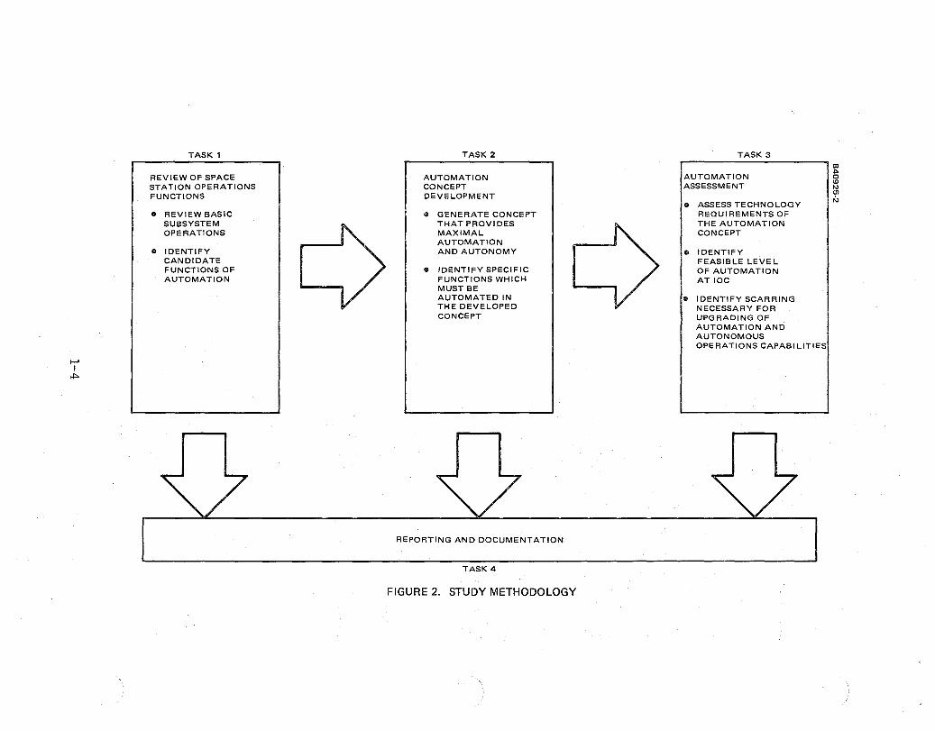
TASK 1
REVIEW OF SPACE STATION OPERATIONS FUNCTIONS
• REVIEW BASIC SUBSYSTEM OPERATIONS
• IDENTIFY CANDIDATE FUNCTIONS OF AUTOMATION
TASK 2
AUTOMATION CONCEPT DEVELOPMENT
• GENERATE CONCEPT THAT PROVIDES MAXIMAL AUTOMATION AND AUTONOMY
• IDENTIFY SPECIFIC FUNCTIONS WHICH MUST BE AUTOMATED IN THE DEVELOPED CONCEPT
REPORTING AND DOCUMENTATION
TASK 4
FIGURE 2. STUDY METHODOLOGY
TASK 3
AUTOMATION ASSESSMENT
• ASSESS TECHNOLOGY REQUIREMENTS OF THE AUTOMATION CONCEPT
• IDENTIFY FEASIBLE LEVEL OF AUTOMATION ATIOC
• IDENTIFY SCARRING NECESSARY FOR UPGRADING OF AUTOMATION AND AUTONOMOUS OPERATIONS CAPABILITIES

The second task was the development of automated and autonomous operation concepts. The functional decomposition of Task 1 forms the basis for the identification of specific functions that require automation in the developed concept.
Task 3 assessed the impact of the automation concept, in terms of both the benefits of automation and the technology requirements of the concept. The assessment, performed with SRI, provides a modified concept with a level of automation that would be technically feasible about 10 years after the initial operational capability (IOC) is established. In addition, the task required the identification of feasible levels of automation and design features for IOC to enable the integration of enhanced automation capabilities by future upgrades of hardware and software units.
AUTOMATION CONCEPT
Hughes developed a concept of automation for space station operations which is unconstrained by technology, cost, and schedule considerations. In that concept, the station has an automated system for monitoring and control that detects, isolates, and recovers from failures. Crew members are thus freed from routine monitoring and sequencing through malfunction procedures and can devote most of their working hours in support of payload operations. Automatic speech recognition and synthesis is available on the station to support crew control of the station. This interactive speech input/output system is particularly valuable when a crew member is involved in the support of teleoperation that requires total involvement of his eyes and hands. The video system supporting the teleoperation provides various service, including high definition video and data compression. Data compression is essential for efficient use of the communications links.
Users have a high degree of flexibility in the operations of their payload. They are able to directly command their payload without coordination, scheduling, and possible override by a ground-based mission control,group. Service can be requested by messages between user and space station. If additional communications are required to support recovery from an unanticipated payload problem. These messages are processed automatically and in real time.
At NASA's request we narrowed the broad focus of our study and concentrated on what we jointly concluded were "tent poles" for automation considerations. The agreed upon automation target was communications operations. Specifically, we developed a concept for a space station communications network similar to a telephone network and evaluated the automation processes which might be required in such a network.
The major characteristics of the communications network in this automation concept are: 1) the use of a dedicated K band single access tracking and data relay satellite (TORS) link for all space station ground communications, 2) digitization of all traffic over the system, 3) automated, rea! time control of all communications resources, 4) the use of multibeam phased arrays for communications between the station and
4
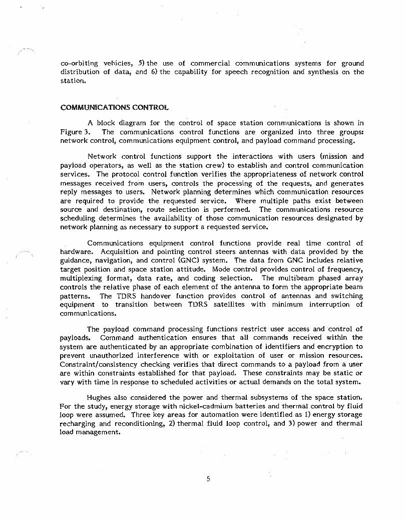
co-orbiting vehicles, 5) the lise of commercial communications systems for ground distribution of data, and 6) the capability for speech recognition and synthesis on the station.
COMMUNICATIONS CONTROL
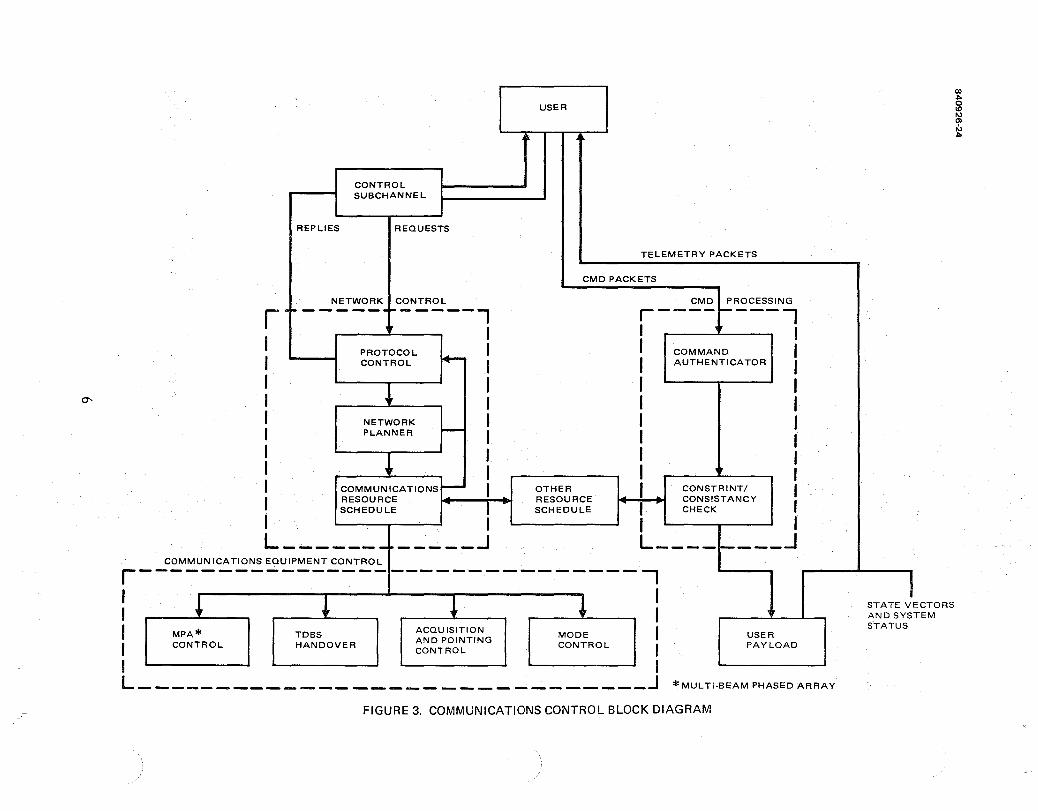
A block diagram for the control of space station communications is shown in Figure 3. The communications control functions are organized into three groups: network control, communications equipment control, and payload command processing.
Network control functions support the interactions with users (mission and payload operators, as well as the station crew) to establish and control communication services. The protocol control function verifies the appropriateness of network control messages received from users, controls the processing of the requests, and generates reply messages to users. Network planning determines which communication resources are required to provide the requested service. Where multiple paths exist between source and destination, route selection is performed. The communications resource scheduling determines the availability of those communication resources designated by network planning as necessary to support a requested service.
Communications equipment control functions provide real time control of hardware. Acquisition and pointing control steers antennas with data provided by the guidance, navigation, and control (GNC) system. The data from GNC includes relative target position and space station attitude. Mode control provides control of frequency, multiplexing format, data rate, and coding selection. The multibeam phased array controls the relative phase of each element of the antenna to form the appropriate beam patterns. The TDRS handover function provides control of antennas and switching equipment to transition between TDRS satellites with minimum interruption of communications.
The payload command processing functions restrict user access and control of payloads. Command authentication ensures that all commands received within the system are authenticated by an appropriate combination of identifiers and encryption to prevent unauthorized interference with or exploitation of user or mission resources. Constraint/consistency checking verifies that direct commands to a payload from a user are within constraints established for that payload. These constraints may be static or vary with time in response to scheduled activities or actual demands on the total system.
Hughes also considered the power and thermal subsystems of the space station. For the study, energy storage with nickel-cadmium batteries and thermal control by fluid loop were assumed. Three key areas for automation were identified as 1) energy storage recharging and reconditioning, 2) thermal fluid loop control, and 3) power and thermal load management.
5
REPLIES
CONTROL SUBCHANNEL
REQUESTS
USER
TELEMETRY PACKETS
CMD PACKETS
NETWORK CONTROL CMD PROCESSING r·· -----.~-----., r----~----,
I I I
PROTOCOL """- " CONTROL ,.,.--
I I I I ~ I , NETWORK ,
I PLANNER --- I I I , I + I , COMMUNICATIONS --- I I RESOURCE
I SCHEDULE I OTHER RESOURCE SCHEDULE
COMMAND AUTHENTICATOR
CONSTRINTI CONSISTANCY CHECK
L ____________ ...J L ________ J COMMUNICATIONS EQUIPMENT CONTROL r-------------------------------j
: l ~ ~ ~: I MPA* TDBS ACQUISITION MODE I
CONTROL HANDOVER AND POINTING CONTROL I CONTROL'
I I L ______________________________ J
USER PAYLOAD
* MULTI-BEAM PHASED ARRAY
FIGURE 3. COMMUNICATIONS CONTROL BLOCK DIAGRAM
I STATE VECTORS AND SYSTEM S-TATUS
AUTOMA nON ASSESSMENT
The impact of the complete automation of the communications control functions was evaluated. Using our experience in the design and development of such diverse communications systems as the demand assignment system for the Indonesian telephone network and the Defense Department's MILST AR satellite communication system, we assessed the technology required for an automated implementation of each communications control function. This assessment is summarized in Table 1.
Three technology areas that potentially offer significant automation capabilities were also reviewed. These areas are: 1) digital telephony, 2) automatic speech recognition and synthesis, and 3) data compression. The digital telephony system offers approaches, standards, and services that can lead to automated communications for the space station with relatively low development costs and high flexibility for internetting with existing commercial communications systems. Speech recognition and synthesis makes versatile man/machine interactions possible. The last, data compression/ decompression, is the key to efficient use of precious communications resources.
RECOMMENDA nONS
Our review of subsystems and operations and our development of an automation concept for the space station has lead us to six key recommendations for enhanced user accommodation and autonomous operations capability. These recommendations are:
1) That the space station communications system be designed as an end-to-end system that provides communications services between user and equipment;
2) That commercial digital telephony standards be incorporated into the space station communications systems;
3) That user requests for communication services be processed by an automated, real time system and that it provide for demand assignment of selected communications services;
4) That short-term planning and scheduling of space station resources be performed on the station and that it be automated at IOC to the extent necessary to provide demand assignment of selected communications services and crew assistance in scheduling;
5) That an automated payload command screening system be implemented;
6) That automatic speech recognition and synthesis be considered a basic mode of man/machine interaction for space station command and control during the design and development of the station;
7

00
Function
Protocol control
Network planning
Resource scheduler
Acquisition and track I ng contro I
Mode contro I
TORS handover
Multlbeam phased array control
TABLE 1. AUTOMATION OF COMMUNICATIONS CONTROL ASSESSMENT
Capabi I ities
Automated, real time handling of service requests and generat i on of rep lies
Automated, real time routing and determination of resource requirements
Automated, real time allocation of demand assigned resources; semlautomated system for scheduled resources which operates with crew interaction
Automated, real time control of communications equipmenT
IOC
Required Technologies
General purpose processor with throughput of about 500 kips; algorithmic software
General purpose processor with throughput of about 500 kips; algorithmic software
General purpose processor with throughput of about 1 mips; algorithmic software; non rea I time knowledgebased system
General purpose processors with throughput of less than 500 kips; algorithmic software
N/A
N/A
Scarring for Growth
Properly defined interface with protocol control and communications equipment control functions
N/A
2002
Capabi I ities
Same as IOC
Same as IOC
Automated, real Time scheduling of a I I shared resources
Same as IOC
ReQu ired Technologies
Same as IOC
Same as IOC
Real time expert system
Same as IOC

Table 1 (continued)
IOC 2002
Required Scarring ReQu ired Function Capabilities Technologies for Growth Capabilities Technologies
Command Automated, real Existing decryption N/A Same as IOC Same as IOC authentication time control of hardware; relatively
command decryption simple digital logic and verification
Consistency/ AUTomated rea I General purpose Flexibl I ity to AutomaTed real Real time constraint time screening of processor with upgrade checking time screening ru Ie-based checking payload commands throughput of about by replacing of payload expert system
200 kips; algorithmic state mach I ne commands simi lar to software implementation Those deSigned
to ru Ie-based for monitoring implementation applications
7) That the data management system (DMS) and other subsystems of the space station be designed to accommodate fully automated fault detection, isolation, and recovery within the system monitoring function of the DMS. (The automated system itself would be a growth capability.)
These recommendations are intended to provide greater operational capabilities to payload users, to simplify the user interface with the space station system, and to provide the capability for autonomous station operations.
10

1. INTRODUCTION
1.1 PURPOSE AND SCOPE
This study represents Hughes Aircraft Company's participation in the space station automation study in the areas of subsystem control and mission operations. The objective of the space station automation study is to provide input to NASA for the identification of promising automation and robotics technologies that can enhance space station operations. To provide such guidance, the study (managed by Cal Space under direction from NASA Headquarters), was organized as shown in Figure 1. Cal Space established a university/industry panel to provide guidance on applying automation and robotics to the space station and advancing industrial applications through activities of the space station program. The report from this panel will be submitted to NASA's Advanced Technology Advisory Committee (AT AC) for its consideration. The product of the ATAC committee will be recommendations on automation and robotics technologies that will be an integral part of the space station definition and preliminary design contracts.
Supporting the Cal Space panel are the NASA design and technology teams. SRI International, as the technology team, provided forecasts of automation and robotics technology and assessed the feasibility of automation concepts developed by the design team.
Each member of the design team studied a specific aspect of space station operations to develop innovative and technologicalJy advanced automation concepts. The members of this team and their study focuses were Boeing (man/machine interface), General Electric (space manufacturing), Martin Marietta (space assembly), TRW (satelJite servicing), and Hughes (subsystem operations).
Hughes was assigned the task of developing an automation concept for the autonomous operation of space station subsystems. The objective of this study was to identify those functions associated with the operations of such subsystems as electric power, thermal control, and communications and tracking.
840925WP 1-1

f-' I
N
TECHNOLOGY TEAM
SRI
I
HQ DIRECTION
HERMAN LUM
POWELL
STUDY MANAGEMENT
CAL SPACE
UNIVERSITYI INDUSTRY
COMMITTEE
NASA DESIGN TEAM
POWELL, HOOK BAC, GE, HAC, MMC, TRW
I
NASAATAC
COHEN
SENIOR TECHNICAL COMMITTEE
DR. FROSCH, CHAIRMAN
PHASE B
CONTRACTORS
FIGURE 1. SPACE STATION AUTOMATED STUDY ORGANIZATION
1.2 STUDY APPROACH
The Hughes study followed the basic methodology shown in Figure 2. First functions associated with the operations of space station subsystems were identified. This was based on available literature on space station design options and over 300 orbit years of spacecraft operations experience at Hughes.
To provide a study focus and to limit the areas to be evaluated, three subsystems were selected: 1) electric power, 2) thermal control, and 3) communications. To assure that functions essential for autonomous operations were included in the study, an operations function (systems monitoring and control) was included for study in the ~ask.
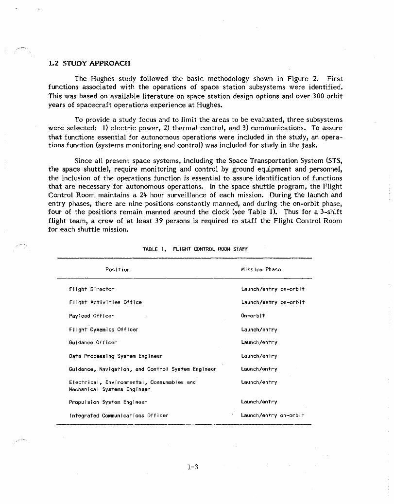
Since all present space systems, including the Space Transportation System (STS, the space shuttle), require monitoring and control by ground equipment and personnel, the inclusion of the operations function is essential to assure identification of functions that are necessary for autonomous operations. In the space shuttle program, the Flight Control Room maintains a 24 hour surveillance of each mission. During the launch and entry phases, there are nine positions constantly manned, and during the on-orbit phase, four of the positions remain manned around the clock (see Table 1). Thus for a 3-shift flight team, a crew of at least 39 persons is required to staff the Flight Control Room for each shuttle mission.
TABLE 1. FLIGHT CONTROL ROOM STAFF
Position
FI ight Director
Flight Activities Office
Pay load Off I cer
Flight Dynamics Officer
Guidance Officer
Data Processing System Engineer
Guidance, Navigation, and Control System Engineer
Electrical, Environmental, Consumables and Mechanical Systems Engineer
Propulsion System Engineer
Integrated Communications Officer
1-3
Mission Phase
Launch/entry on-orbit
Launch/entry on-orbit
On-orbit
Launch/entry
Launch/entry
Launch/entry
Launch/entry
Launch/entry
Launch/entry
Launch/entry on-orbit
TASK 1
REV lEW OF SPACE STATION OPERATIONS FUNCTIONS
o REVIEW BASIC SUBSYSTEM OPERATIONS
o IDENTIFY CANDIDATE FUNCTIONS OF AUTOMATION
TASK 2
AUTOMATION CONCEPT DEVELOPMENT
• GENERATE CONCEPT THAT PROVIDES MAXIMAL AUTOMATION AND AUTONOMY
o IDENTIFY SPECIFIC FUNCTIONS WHICH MUST BE AUTOMATED IN THE DEVELOPED CONCEPT
REPORTING AND DOCUMENTATION
TASK 4
FIGURE 2. STUDY METHODOLOGY
TASK 3
AUTOMATION ASSESSMENT
o ASSESS TECHNOLOGY REQUIREMENTS OF THE AUTOMATION CONCEPT
• IDENTIFY FEASIBLE LEVEL OF AUTOMATION ATIOC
It IDENTIFY SCARRING NECESSARY FOR UPGRADING OF AUTOMATION AND AUTONOMOUS OPERATIONS CAPABILITIES
Additional real time support is provided to the Flight Control Room staff by personnel of the Multipurpose Support Room. Given the enormous complexity of continuous space station operations in comparison to a 7 day shuttle mission, the size of the required ground crew will pose significant problems unless many of the operations tasks are automated.
The second task of the study was the development of automated and autonomous operation concepts. The functional decomposition of Task 1 forms the basis for the identification of specific functions that require automation in the developed concept.
Task 3 assessed the impact of the automation concept, in terms of both the benefits of automation and the technology requirements of the concept. The assessment, performed with SRI, provides a modified concept with a level of automation that would be technically feasible about 10 years after the initial operational capability (IOC) is established. In addition, the task required the identification of feasible levels of automation for IOC and design features required at IOC to enable the integration of enhanced automation capabilities by future upgrades of hardware and software units.
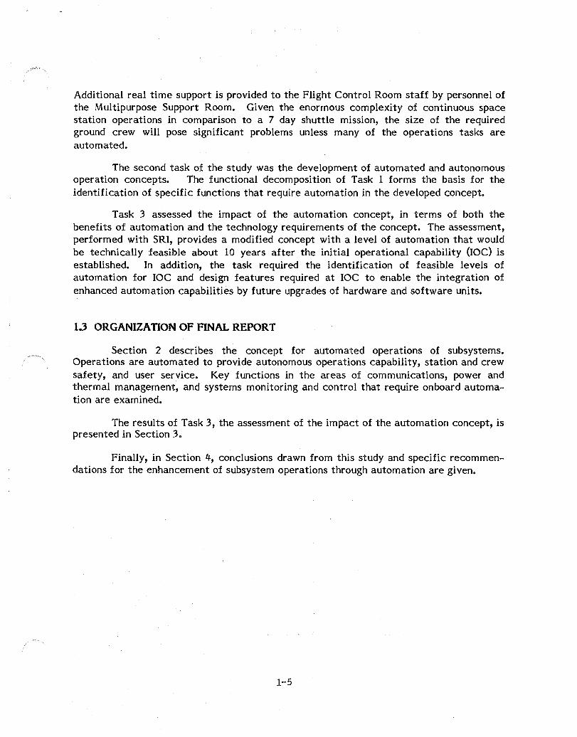
1.3 ORGANIZATION OF FINAL REPORT
Section 2 describes the concept for automated operations of subsystems. Operations are automated to provide autonomous operations capability, station and crew safety, and user service. Key functions in the areas of communications, power and thermal management, and systems monitoring and control that require onboard automation are examined.
The results of Task 3, the assessment of the impact of the automation concept, is presented in Section 3.
Finally, in Section 4, conclusions drawn from this study and specific recommendations for the enhancement of subsystem operations through automation are given.
1-5
2. AUTOMATED SUBSYSTEMS OPERATIONS
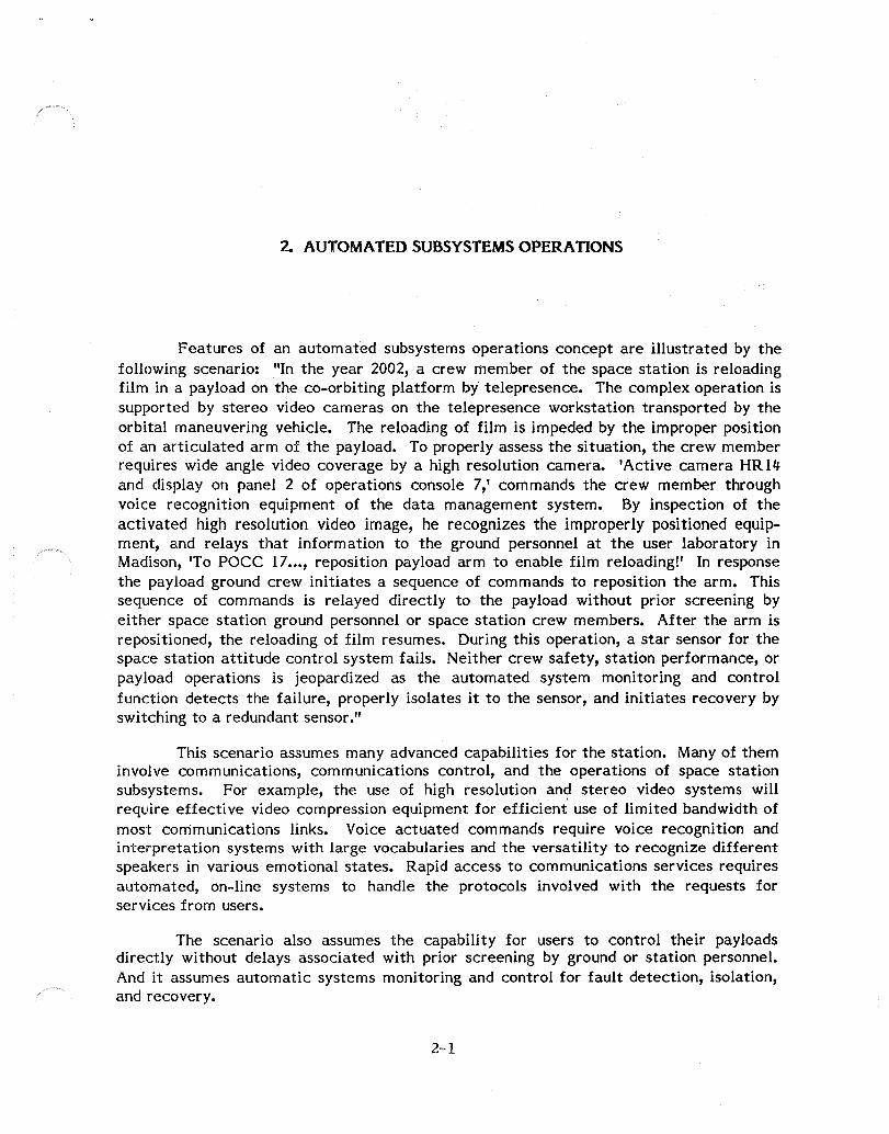
Features of an automated subsystems operations concept are illustrated by the following scenario: "In the year 2002, a crew member of the space station is reloading film in a payload on the co-orbiting platform by telepresence. The complex operation is supported by stereo video cameras on the telepresence workstation transported by the orbital maneuvering vehicle. The reloading of film is impeded by the improper position of an articulated arm of the payload. To properly assess the situation, the crew member requires wide angle video coverage by a high resolution camera. 'Active camera HR14 and display on panel 2 of operations console 7,' commands the crew member through voice recognition equipment of the data management system. By inspection of the activated high resolution video image, he recognizes the improperly positioned equipment, and relays that information to the ground personnel at the user laboratory in Madison, 'To POCC 17 ••• , reposition payload arm to enable film reloading!' In response the payload ground crew initiates a sequence of commands to reposition the arm. This sequence of commands is relayed directly to the payload without prior screening by either space station ground personnel or space station crew members. After the arm is repositioned, the reloading of film resumes. During this operation, a star sensor for the space station attitude control system fails. Neither crew safety, station performance, or payload operations is jeopardized as the automated system monitoring and control function detects the failure, properly isolates it to the sensor, and initiates recovery by switching to a redundant sensor."
This scenario assumes many advanced capabilities for the station. Many of them involve communications, communications control, and the operations of space station subsystems. For example, the use of high resolution an~ stereo video systems will require effective video compression equipment for efficient use of limited bandwidth of most communications links. Voice actuated commands require voice recognition and interpretation systems with large vocabularies and the versatility to recognize different speakers in various emotional states. Rapid access to communications services requires automated, on-line systems to handle the protocols involved with the requests for services from users.
The scenario also assumes the capability for users to control their payloads directly without delays associated with prior screening by ground or station personnel. And it assumes automatic systems monitoring and control for fault detection, isolation, and recovery.
2-1

ACRONYM DEFINITION
EMU EXTRAVEHICULAR MOBILITY UNIT
FF FREE FLYER OTV ORBITAL TRANSFER
VEHICLE OMV ORBITAL MANEUVERING
VEHICLE PLATFORM CO-ORBITING PLATFORM ORBITER SPACE SHUTTLE
ORBITER TORS TRACK ING AND DATA
RELAY SATELLITE TORS GND STA TORS GROUND STATION
DOMSAT DOMESTIC COMMUNICATIONS SATELLITE
POCC PAYLOAD OPERATIONS CONTROL CENTER
MCC MISSION CONTROL CENTER
NUMBER
4
8 1
2
1 2
2
10
FIGURE 3. SPACE STATION COMMUNICATION SYSTEM TOPOLOGY
2-2

The following subsection reviews the functions that must be automated to provide the kinds of capabilities suggested by the scenario.
2.1 COMMUNICA nONS
2.1.1 Communications Concept
In the scenario, communications is envisioned to provide end-to-end services (between ground equipment at a principal investigator's laboratory and his payload instrument, or between a systems engineer's console at the Space Station Operations Center and the thermal management system) and to handle requests for communications services in a responsive, automated way. In the design and operations of user equipment, only the interface between the user end equipment and the communications system, which includes the protocol for requests for communications services, should concern the user. RF characteristics and modulation structure of the TORS system, for example, should be transparent to the user. Users (principal investigators, ground operations personnel, station crew members) should be able to receive communications services on immediate request to enable rapid response to changing conditions of space station system operations or payload operations. Services that could be available on demand might include voice and medium data rate communications.
The space station communications system should provide end-to-end communications services in response to user demand. It should also schedule and provide automated control of the communications resources. The communications system provides for all transmissions between user end equipment (consoles, headsets, cameras, monitors, subsystem units, payload units, etc). Radio frequency (RF) links, optical links, and wire links are included. The topology of the space station communications system is depicted in Figure 3.
The major characteristics of the communications system for this study are: 1) the use of a dedicated Ku-band single access TORS link for primary space station-ground communications, 2) digitization of all traffic over the system, 3) automated, real time control of all communications resources, 4) the use of multibeam phased arrays for communications between the station and co-orbiting vehicles, 5) the use of commercial communications systems for ground distribution of data, and 6) the capability for speech recognition and synthesis on the station.
TDRS Space-Ground Link. A critical link in this system is the space-to-ground link supported by the tracking and data relay satellites (TORSs). This link will carryall communications between the space station and ground operations centers (the Space Station Operations Center and the Payload Operations Control Centers). The TORS system consists of two satellites; one stationed at 4loW longitude, TORS-East, and the other at 1710 W longitude, TORS-West. The positioning provides nearly continuous coverage for low earth orbiting satellites while maintaining line-of-sight to the White Sands Ground Terminal (WSGT).
2-3

As shown in Figure 4, the geometry of the orbits is such that a zone of exclusion exists in which the lines-of-sight between the space station and each of the TORS are obscured by the earth. This zone of exclusion for the space station at its nominal 500 km altitude will reduce TORSS coverage to approximately 85 percent. Figure 5 shows the geographical location of this zone of exclusion for a 600 km orbit. Over the proposed design altitude range for the space station of 463 to 555 km, the zone of exclusion will be at least as large as that shown in Figure 5.
At some point in each of the station's orbits of approximately 95 minutes, the TORS communications link must be transferred from TORS-West to TORS-East and about 45 minutes later will be interrupted in the zone of exclusion.
Transfer of the space station communications link from one TORS system to the other at appropriate times in the orbit will have to be accomplished without assistance or control by onboard or ground personnel. This automation of the TORS handover function is described in further detail in 2.1.2.2.
An All-Digital System. The contemplated space station communications system is an alldigital system. All analog inputs are digitized, encoded, and compressed prior to transmission within the system. The digital approach makes it possible to encrypt digitized video and voice, as well as processing data. Similarly, communications to analog output devices are decrypted, decompressed, decoded, and restored to analog form.
TDRS EAST LONGITUDE 41° WEST
\ \ \
"-'-
~ 746 MI LE ZONE OF EXCLUSION
FIGURE 4. TORS SATELLITES AND SPACE STATION SIMPLIFIED GEOMETRY
2-4

N I
u-t
90
80
70
60
50
40
30
20
10
0
-10
-20
-60
-70
-80
.' ""
TDRS-WEST X
TDRS LATITUDE = 0 deg TDRS SEPARATION = 130 deg GEOMETRIC ZONE FOR 600 KM ALTITUDE
•
~oL-____ ~ ____ -L ____ ~ ______ L-____ ~ ____ -L ____ -L ____ -J~ ____ ~ ____ ~ ____ -L ____ ~ ______ ~ ____ J-____ -L ____ ~ ____ ~~ __ ~
-180 -160 -140 -120 -100 -80 -60 -40 -20 o 20 40 60 80 100 120 140 160 180
FIGURE 5, TDRSS ZONE OF EXCLUSION
.------,-- - -
274.176 Mbps
44.736 Mbps
44.736 Mbps
44.736 Mbps
44.736 Mbps
44.736 Mbps
44.736 Mbps
6.312 Mbps
6.312 Mbps
.., \
\ \ \ \ 6.312
\ Mbps
\ \
6.312 Mbps \
\ \ \
6.312 Mbps \
\ \ \ 6.312
\ Mbps
\ \ 6.312
Mbps
., \ \ \ \ \ \ \ \ \ \ \ \ \ \ \ \ \ \ \ \
1.544 Mbps
1.544 Mbps
1.544 Mbos
1.544 Mbps
56 kbps
56 kbps
., 56 kbps
\
56 kbps \ \ \ \ \ \ \ \ \
'"' \ ,.. \ \ \
56 kbps
56 kbps
\ 56 kbps
\ \ \ 56 kbps
'"'
'------'---- \ \..
\ l l'---__ ....
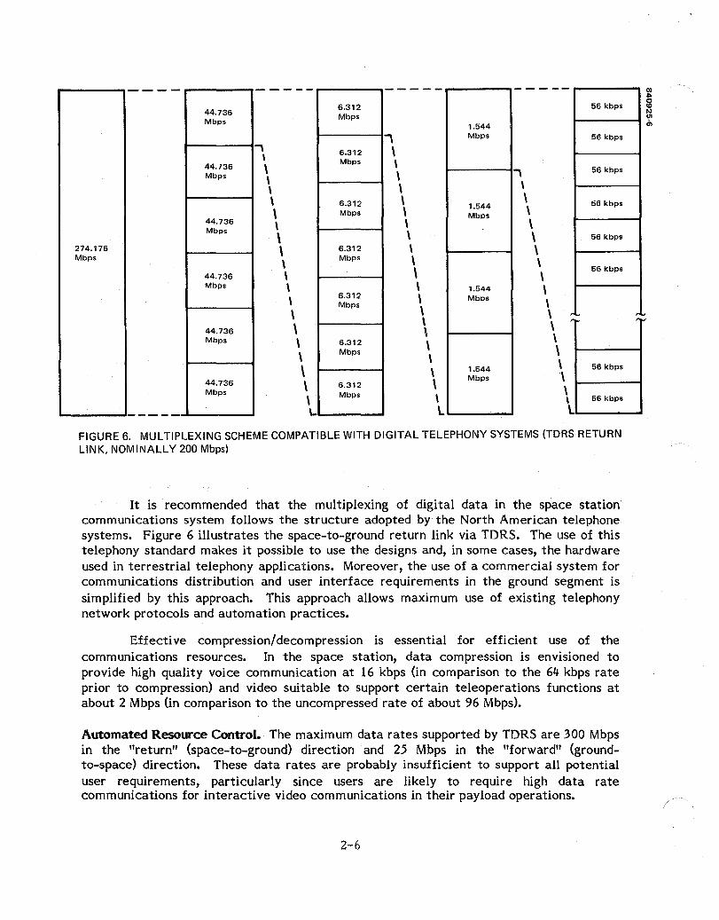
FIGURE 6. MULTIPLEXING SCHEME COMPATIBLE WITH DIGITAL TELEPHONY SYSTEMS (TDRS RETURN LINK, NOMINALLY 200 Mbps)
It is recommended that the multiplexing of digital data in the space station communications system follows the structure adopted by the North American telephone systems. Figure 6 illustrates the space-to-ground return link via TDRS. The use of this telephony standard makes it possible to use the designs and, in some cases, the hardware used in terrestrial telephony applications. Moreover, the use of a commercial system for communications distribution and user interface requirements in the ground segment is simplified by this approach. This approach allows maximum use of existing telephony network protocols and automation practices.
Effective compression/decompression is essential for efficient use of the communications resources. In the space station, data compression is envisioned to provide high quality voice communication at 16 kbps (in comparison to the 64 kbps rate prior to compression) and video suitable to support certain teleoperations functions at about 2 Mbps (in comparison to the uncompressed rate of about 96 Mbps).
Automated Resource Control. The maximum data rates supported by TDRS are 300 Mbps in the "return" (space-to-ground) direction and 25 Mbps in the "forward" (groundto-space) direction. These data rates are probably insufficient to support all potential user requirements, particularly since users are likely to require high data rate communications for interactive video communications in their payload operations.
2-6

Careful planning and scheduling of the communications resources, in conjunction with the planning of the use of other station resources such as electrical power and crew support, will be critical to the effective use of the space station.
Communications resource scheduling is a major function of communications control. Detailed description of resource scheduling is presented in 2.1.2.1.
Phased Array System for Co-orbit Communications. The space station will have to communicate with co-orbiting free flyers, platforms and vehicles with multibeam phased array antennas. Each beam formed by such an array can be separately steered and shaped. This capability will allow formation of high gain, narrow beams for communications with vehicles at long range and low gain, wide beams at short range, as shown in Figure 7. Control of the multibeam phased array antenna is a critical function associated with the control of communications equipment.
Speech Recognition and Synthesis. Crew members will operate the station and its various payloads and control operations of vehicles and teleoperations systems in the vicinity of the station from the mUltipurpose applications consoles. Demands on the crew member while operating at these consoles will be intense, especially during teleoperations that require full involvement of the hands and eyes of the operator. To support the crew in such operations, the automated communications system will have to provide command and control by voice input/output system. The system will recognize continuous speech, not just isolated words, spoken by a crew member to control displays, communications, and other support functions. Although it does not need to provide recognition of totally unrestricted, natural speech, the system will have to correctly respond to a mUltiplicity of sentence structures and to variable phrasing of speech that are consistent with well-defined tasks onboard the station. The recognition system will have to incorporate word recognition, syntax analysis, and semantics analysis to provide a correct response to directions spoken by the user with apparent naturalness.
While the speech synthesis function on the station will be a limited vocabulary system, it will be based on design concepts for unlimited text-to-speech synthesis systems. It incorporates phonological rules to determine proper selection of basic sounds (phonemes) and transitions beween phonemes, as well as intonation rules based on syntax to provide improved rhythm of the synthesized speech.
The voice input/output system for the space station will be designed for interaction between crew member and the automated system. The speech recognition system will continuously adapt to changes in the user's voice. The feedback from machine to user will be provided by synthesized speech. This voice interactive system could also provide the capability for improved speech synthesis by modification of the rules used to generate the speech dynamically using human feedback.
2-7

-"} --,- -/
.......... -- /' ........ """'" ...,..../ / ........ """"
/" ...,.... ..........
// ......... ----........ """" --.......... .-'-
~ /""",,-::.-'---/---..... 0
I '" I '\ I \ I \ I \ \ \ \ - } "\ / , __ / "NEAR"
FIGURE 7. BEAM SHAPING BY MULTIBEAM PHASED ARRAY
2-8
~ 16
2000 km tl .:..

2.1.2 CommWlications Control
A block diagram for the control of space station communications is shown in Figure 8. The communications control functions are organized into three groups: 1) network control, 2) communications equipment control, and 3) payload command processing.
Network control functions support the interactions with users (mission and payload operators, as well as the Station crew) to establish and control communications services. The protocol control function verifies the appropriateness of network control messages received from users, controls the processing of the requests, and generates reply messages to users. Network planning determines which communications resources are required to provide the requested service. Where multiple paths exist between source and destination, route selection is performed. The Communications Resource Scheduling determines the availability of those communications resources designated by network planning as neccesary to support a requested service.
Communications equipment control functions provide real time control of hardware. Acquisition and pointing control steers antennas with data provided by the guidance, navigation, and control (GNC) system. The data from GNC includes relative target position and space station attitude. Mode control provides control of frequency, multiplexing format, data rate, and coding selection. The multibeam phased array controls the relative phase of each element of the antenna to form the appropriate beam patterns. The TDRS handover function provides control of antennas and switching equipment to transition between TDRS satellites with minimum interruption of communications.
The payload command processing functions restrict user access and control of payloads. Command authentication ensures that all commands received within the system are authenticated by an appropriate combination of identifiers and encryption to prevent unauthorized interference with or exploitation of user or mission resources. Constraint/consistency checking verifies that direct commands to a payload from a user are within constraints established for that payload. These constraints may be static or may vary with time in response to scheduled activities or actual demands on the total system.
2.1.2.1 Network Control. The automated network control concept provides "user friendliness" by enabling users to request and control communications almost as easily as making a telephone call. Toward this end, network control provides automated request handling, demand assignment of at least certain classes of services, and automated routing of communications channels from source to destination.
Network control in the automated subsystem operations concept assumes the partitioning of communications services,in three categories as shown in Table 2. Status telemetry from space station subsystems and payloads, as well as commands to those systems, are transmitted via a message-switched (or possibly a packet-switched) subnetwork of the communications system. Other message-oriented data communications (such as text messages) could also be accommodated by this subnetwork.
2-9

N I
I-' o
REPLIES
CONTROL SUBCHANNEL
REQUESTS
USER
TELEMETRY PACKETS
CMD PACKETS
NETWORK CONTROL CMD PROCESSING r -~ - -----r-o- -----, r----~----,
I I I
PROTOCOL l-.. II CONTROL r---
I I I I t_ I I NETWORK I I PLANNER r--- I I I I I • I I COMMUNICATIONS r--- I I RESOURCE
I SCHEDULER I L ____________ ...1
COMMUNICATIONS EQUIPMENT CONTROL
OTHER RESOURCE SCHEDULER
r-------------------------------,
:! ~ ~ ~: I MPA* TDRS ACQUISITION MODE I
CONTROL HANDOVER AND POINTING CONTROL I CONTROL I I I L _________________________ ~ ____ J
COMMAND A.UTHENTICATOR
CONSTRAINT/ CONSISTANCY CHECK
USER PAYLOAD
*MULTI-BEAM PHASED ARRAY
FIGURE 8. COMMUNICATIONS CONTROL BLOCK DIAGRAM
I STATE VECTORS AND SYSTEM STATUS

TABLE 2. CATEGORIES OF COMMUNICATION SERVICES
Service Type
Video High rate data
Voice Medium rate data
Command Telemetry Message-oriented data
*Up to tens of Mbps. **Approxlmately 10 to 100 kbps.
SWitching Approach
Circuit switched
Circuit switched
Message switched (packet switched?)
Assignment Approach
Scheduled
Demand assignment
Contention
The message-switched service provides guaranteed correct delivery. Each message is relayed through the network link by link. At each network node, a message is received in its entirety, inspected for error, then retransmitted across the next link toward its ultimate destination. If an error is detected in a received message, a request for a retransmission is sent by the receiving node. Thus correct delivery can be assured so long as a physical link exists for some time after the message is ready to transmit. Messages are stored at a node if it cannot be further relayed due to a temporary outage of any link.
The bulk of the communications (video, voice, and data) is circuit-switched. Initiation, modification, and termination of such services are accomplished by information exchange between a user (a mission or payload operator or station crew member) and the communications control system following a specified protocol.
Protocol Control. An example of a protocol for the control of communications services is the signaling in commercial telephone systems as shown in Figure 9. The state transition diagram in the figure represents the various states of a subscriber's telephone set and the events, leading to or resulting from signals from the local office, that are associated with state transitions. In the telephone system, signaling with the user is accomplished by conditions, pulses, or tones on the lines between the user and the local office.
A protocol assumed in the automation concept is one based on the exchange of messages. A candidate message set is depicted in Table 3. The role of each of the messages in the control of a communications service is illustrated in the state transition diagram of Figure 10. In that figure, an initiating event and a response are associated with each allowed transition between states. An initiating event may be an action by the user (i.e., a user request) or a message received from the system (e.g., a ring up). A response is a message generated by the user or the system in response to the initiating event.
2-11

FIGURE 9. TELEPHONE SYSTEM STATE TRANSITION DIAGRAM
2-12

USER REQUEST TERMINATION REQUEST
LEGEND:
RINGUP __ CALL ANSWER
TERMINATION NOTICE
SERVICE ASSIGNMENT
INITI.ATING EVENT RESPONSE
ACK
USER REQUEST SERVICE REQUEST
SERVICE ASSIGNMENT ACK
FIGURE 10. MESSAGE ORIENTED PROTOCOL STATE TRANSITION DIAGRAM
2-13

----FINAL ROUTES
--- HIGH USAGE ROUTES
FIGURE 11. TELEPHONE SYSTEM ROUTING HIERARCHY
2-14
(I)
REGIONAL CENTERS g '" ~ ..
SECTIONAL CENTER
PRIMARY CENTER
TOLL CENTER
END OFFICE
SUBSCRIBER

TABLE 3. CANDIDATE MESSAGE SET FOR NETWORK CONTROL PROTOCOL
Message Type
Service request
Ring-up
Call answer
Acknowledgment (ACK)
Service assignment
Termination request
Termination notice
Description
Request for basic communications services providing information such as: type of service, source, destination, start time
Message generated by system to inform destination terminal that communications link is being set up
Response to ring-up message which terminal accepts or rejects attempt to establish link
Notification of receipt of message
Notification to terminal of parameters of communications services being established
Request by user for release of existing communications service
Notification to terminal that communications service will be withdrawn
The message-oriented network control protocol requires a channel for control that is separate from the communications channel under control. This requirement for overhead communications capacity is offset by the flexibility for control of a wide range of different services and the potential for accommodation of evolving protocol requirements of this approach.
Network Planning. The second function associated with network control is designated network planning in the block diagram (Figure &) for communications control. Network planning involves the determination or resource types (e.g., RF and baseband equipment type, channel type), the control of link-by-link routing of a communications path, and the selection of communications modes on the various links to trade capacity for performance (in the bit error rate sense).
Routing in a telephone system is performed office-to-office in a hierarchy as illustrated in Figure 11. It is initiated at the local office of the subscriber originating the call. A direct path to the local office of the destination party is attempted. If such a path is not available, a path to a higher level office is obtained. A call destined for an office outside the local chain is generally routed up the hierarchy; a call destined for an office of lower rank within the local chain proceeds down the chain. At the highest level, calls cross from one chain to another. When high usage routes are available, the final or backbone route is bypassed to establish a path toward the destination local office. The conventional routing strategy is a far-to-near approach in which the first choice route is one which advances a call as far as possible from the origin using the final route to measure distance. Subsequent choices are ordered by decreasing distance.
2-15

FIGURE 12. SPACE STATION SYSTEM COMMUNICATIONS
2-16

Routing in the space station communications system is envisioned to be automated with a procedure similar to that of a telephone system. However, control of routing throughout the space segment will be controlled on the space station. This centralization of routing control places the complexity of communications processing on the station where maintenance, upgrading, and modification of equipment is more economical.
Resource Scheduling. The third key function of network control is resource scheduling. Among the circuit-switched services, video and high rate data are scheduled services; voice and medium rate data are demand assigned. Scheduling offers effective use of limited resources, while demand assignment provides flexibility to respond to unanticipated circumstances. Resource scheduling must request video and high data rate services on the basis of user requirements, system capabilities and constraints, and overall priorities. In general, the scheduling of communications resources must be coordinated with the scheduling of all other shared station resources.
For demand assigned resources, the function of the resource scheduler is reduced to the real time allocation of required resources and the preemption and reallocation for high priority requests.
The automated network control involves processing on the station and at the Space Station Operations Center (SSOC). Processing on the station handles user service requests that originate in the space segment (on the station itself, in an EMU, or on an orbiter), controls routing throughout that segment, schedules, and allocates the communications resources of that segment. Processing at the SSOC performs similar functions related to the ground segment (the SSC, the various POCCs, and the White Sands Ground Terminal of the TORS system). This partitioning of functions reduces the complexity of equipment on the station, reduces the overhead data exchanges through the critical ground-space links through TORS, and provides the station with the capability to maintain communications operations in the space segment through outages of the TORS links.
2.1.2.2 Communications Equipment Control. The automation of the space station communications equipment control system suggests that a comparison of the space shuttle orbiter (SSO) antenna control system with that required of the space station would be useful. The SSO is designed to be able to communicate with the ground both directly and via TORS, with EVA, and with detached and attached payloads. The space station, however, must be capable of communicating with the ground, EMUs, and payloads, but in addition it must have communication links to SSO, free flyers, OMVs, and OTVs (Figure 12). These simultaneous user requirements pose significant challenges in the design of an antenna control system.
In addition, the variations in relative positions and transmitting powers of the different uses impose a severe dynamic range requirement. Vehicles near the station and with high transmitting power must not disrupt the transmission of distant, low power users. The structural complexity of the space station exacerbates another problem, the structural blockage of antennas. For example, a complete 1 km sphere of coverage is
2-17
12r-------------------------~------------------------_, NOTE: SCAN STARTING POINT IS AT (0.0)
WHICH REPRESENTS INITIAL ANTENNA BORESIGHT
10 *a AND (3 = ORTHOGONAL AXIS
tJ) W w a:
8
(!) 6 w Cl
*' !!? 4 X <{ <n. Z 2
IZ w ~ 01--+ ....... ~+--lI-+--1-_4_4 ...... ~+-I__+_--I~+_+-I__+~ W o <{ -' 0.. -2 !!? Cl a: <{ -4 -' :J (!)
~ -6
-8
_10L-__ 1-__ _L __ -1 __ ~~~~=:L_ __ 1_ __ _L __ _1 __ ~ -10 -8 -6 -4 -2 o 2 4 6 11')
ANGULAR DISPLACEMENT IN a AXIS*. DEGREES
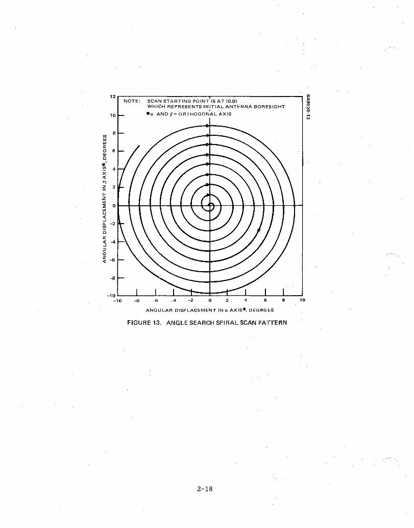
FIGURE 13. ANGLE SEARCH SPIRAL SCAN PATTERN
2-18
required for EVAs. Any modification or addition to the space station must not detract from this coverage.
In addition to all of the above considerations, antenna pointing will be a much more difficult task for space station than for the SSO. The large number of users necessitates wider bandwidths. Since the bandwidths at low frequencies are already becoming congested, this wide bandwidth requirement implies the use of higher frequencies and therefore narrower beam widths and hence antenna pointing difficulties.
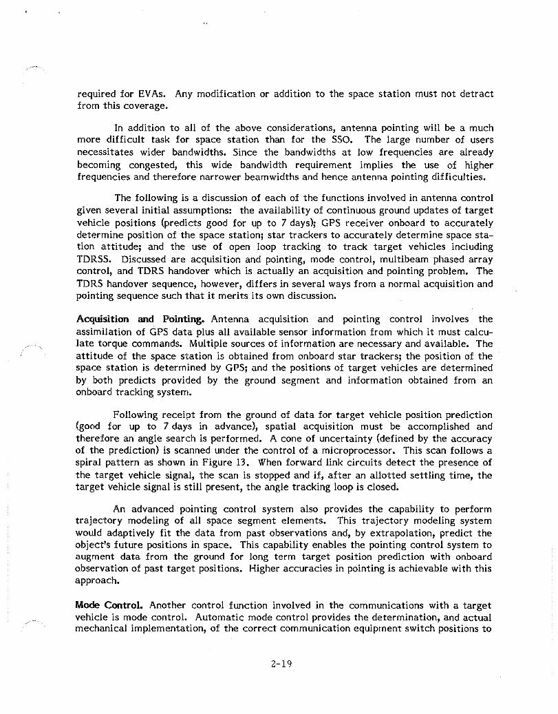
The following is a discussion of each of the functions involved in antenna control given several initial assumptions: the availability of continuous ground updates of target vehicle positions (predicts good for up to 7 days); GPS receiver onboard to accurately determine position of the space station; star trackers to accurately determine space station attitude; and the use of open loop tracking to track target vehicles including TDRSS. Discussed are acquisition and pointing, mode control, multi beam phased array control, and TDRS handover which is actually an acquisition and pointing problem. The TDRS handover sequence, however, differs in several ways from a normal acquisition and pointing sequence such that it merits its own discussion.
Acquisition and Pointing. Antenna acquisition and pointing control involves the assimilation of GPS data plus all available sensor information from which it must calculate torque commands. Multiple sources of information are necessary and available. The attitude of the space station is obtained from onboard star trackers; the position of the space station is determined by GPS; and the positions of target vehicles are determined by both predicts provided by the ground segment and information obtained from an on board tracking system.
Following receipt from the ground of data for target vehicle position prediction (good for up to 7 days in advance), spatial acquisition must be accomplished and therefore an angle search is performed. A cone of uncertainty (defined by the accuracy of the prediction) is scanned under the control of a microprocessor. This scan follows a spiral pattern as shown in Figure 13. When forward link circuits detect the presence of the target vehicle signal, the scan is stopped and if, after an allotted settling time, the target vehicle signal is still present, the angle tracking loop is closed.
An advanced pointing control system also provides the capability to perform trajectory modeling of all space segment elements. This trajectory modeling system would adaptively fit the data from past observations and, by extrapolation, predict the object's future positions in space. This capability enables the pointing control system to augment data from the ground for long term target position prediction with on board observation of past target positions. Higher accuracies in pointing is achievable with this approach.
Mode Control. Another control function involved in the communications with a target vehicle is mode control. Automatic mode control provides the determination, and actual mechanical implementation, of the correct communication equipment switch positions to
2-19

-"} .---- -/ /"'--- /' /"'-- --/
,/ --/'" /"'/
,/ --,// /"/'"
/"'/" ---/'" ---
~ //_.....-""'-/_-
....... 0 I ',-I " I \ I \ I \ \ \
\ - } " / , __ / "NEAR"
~ g ~
2000 km ~
~
FIGURE 14. NEAR AND FAR RANGES (BEAMWIDTH/DIRECTIVITY/GAIN POSSIBILITIES)
2-20

enable a particular mode. If, for instance, video transmission were not required at a particular time, then a wide band communication link would not be optimally used. A mode control system would determine that this was the case and activate the necessary switches at both the receiver and transmitter ends to select a lower data rate commu-nication link. Or, the mode control system might decide to transmit high rate data rather than the video data and therefore switch from the one mode to the other. This system would also be responsible, for example, for selecting the mode for error correction encoding/decoding or the mode for modulation.
Multibeam Phased Array Control. A phased array is a directive antenna made up of several, hundreds, or even thousands of individual radiating elements which generate a radiation pattern whose shape and direction is determined by the relative phase and amplitude of the field radiated by each individual element. The direction of the main lobe of the radiation pattern can be steered by properly varying the relative phases. The beamwidth and the sidelobe levels of a phased array antenna are determined by the frequency, the extent of the array, and the spacing between array elements. A multibeam phased array antenna is essentially a system of multiple, superimposed phased arrays. Beamwidth and direction of each beam can be independently controlled to provide high gain coverage of distant vehicles and low gain coverage for near vehicles (Figure 14).
Due to the enormous amount of flexibility inherent in the multibeam phased array system, a large amount of processing capability must be available. Multibeam phased array beam steering requires the assimilation of various information including space station position and attitude, local orientation of the array, and target vehicle position. From this information, a computer must be able to generate the relative azimuth and elevation angles. This information in turn must be translated into the commands for each phase shifter. The beam width, scan limit, and sidelobe level requirements for communications between the space station and the numerous coorbiting vehicles drive design concepts to arrays with several thousand elements. A system supplying phase information for such a complex system will require enormous amounts of computing power.
A distributed processing system lends itself well to the processing requirements of a phased array system of this magnitude. Generation of the relative azimuth and elevation angles might be an additional function performed by the guidance, navigation and control (GNC) system and the translation of pointing angles into phase shifter commands by a dedicated beam steering processor. This division of duties reduces the processing demands on each individual processor and represents a feasible approach to the automated control of the multibeam phased array.
TORS Handover. Each orbit (approximately 95 minutes) of the space station necessitates the handover of the communication link via TDRSS from one TORS to the other. It is desirable to accomplish this task with minimal loss of information.
In order to meet the spatial coverage requirements and to avoid beam obscuration by the space station, multiple space station antennas are required. For purposes of
2-21

TORS EAST LONGITUOF 41° WEST
\ \ \
"-'------
t 746 MI LE ZONE OF EXCLUSION
FIGURE 15. TORS SATELLITES AND SPACE STATION SIMPLIFIED GEOMETRY
2-22

this discussion, the space station communication subsystem uses two onboard antennas to search for and acquire the TORSs within a cone of uncertainty about the predicted position generated onboard the station. Two onboard antennas are used to enable the space station to execute a make-before-break operation to establish a communication link with TORS with little loss of information during the handover. The ground station in White Sands, New Mexico, is equipped with three antennas; one for each TORS and a standby. Thus, there is a continuous link between each TORS and the ground. When handover is required, the westernmost space station antenna is providing the communication link with TORS-West (see Figure 15). The autonomous acquisition and pointing system uses its knowledge (via GPS) of the station's position in space relative to the earth and a prediction of the position of TORS-East received from the guidance, navigation, and control system to determine the correct pointing direction required to acquire the TORSS. The system then commands the easternmost space station antenna to perform an angle search for the TORSS. Once acquired, the routing is switched from TORSSWest to TORSS-East.
2.1.2.3 Payload Command Processing. The concept for automated subsystems operations provides payload operators with direct communications services between their Payload Operations Control Centers (POCCs) and their payloads on the space station, the coorbiting platform, and free flyers. For example, a user can obtain on demand a channel for data transmission to his POCC when his payload has accumulated sufficient data. The automated, real time processing described in Section 1.1.1 provides that capability. Even greater flexibility in the user's operation of his payload is provided by the automated payload command processing on the station. The user is free to control his payload, within defined limitations, without coordination with mission operations control personnel.
The payload command processing function authenticates a command received for any payload, then verifies that the command will not violate constraints defined for that payload. These constraints assure that user operation of their payload does not create unacceptable risks to other payload operations, to the station, or to the crew. Because this function is automated onboard the station, users can command their payloads without relaying command sequences to a centralized mission control group for coordination, scheduling, and possible override.
Command Authentication. Payload command processing consists of the command authentication and the constraint/consistency checking functions. The former function verifies the integrity of user command by commercial grade encryption hardware (e.g., implementations of the Oata Encryption Standard). To prevent exploitation of the payload by unauthorized repetition of an encrypted valid command previously transmitted by the user, each command includes a unique identifier, a time-of-day field or a non repeated command sequence number.
2-23

Constraint/Consistency Checking. The constraint/consistency checking function screens payload commands based on the content and the context of the commands. Conditions on the station, the microgravity (0.00001 G) maintenance mode, contamination (particulates, fluid, gas, electric fields, and magnetics fields) restriction modes, and assigned priorities of payloads (e.g., control assignment for shared instrument mounts) and so forth, define limits within which a payload must operate. Access to shared resources, such as electric power, thermal dissipation capacity, water and oxygen, is an important element of such limits of operations.
Certain payloads may require reloading of the software of imbedded computers. Unrestricted reloading of such software may enable the inadvertent generation of a hazardous condition on the station during subsequent operation of the payload. To avoid such a risk, all such computer reloads require coordination with the Space Station Operations Center. The reloads must be verified to assure that the objectives of command checking are not circumvented.
Processing of payload commands will not be required of all payloads. Payloads with modest resource requirements and benign interactions with the rest of the station can be sufficiently controlled by multiple serial inhibit/enable switches on critical payload actuators. A microgravity experiment that requires at most a few watts of power, that generates essentially no momentum, and that is nearly totally self-contained (except for its power, command, and status telemetry interfaces) is potentially such a payload. Screening of commands could be waived for such a payload provided that detailed review of the payload design and fabrication verifies the benign nature of that payload.
2.2 ELECTRICAL POWER AND THERMAL SUBSYSTEM
This subsection presents a top level functional description of the automated space station electrical power and thermal subsystems. Three specific areas within subsystems identified as key functions for automation are:
1) Energy storage recharging and reconditioning;
2) Thermal fluid-loop control; and
3) Power and Thermal load management.
Energy storage recharging and reconditioning was chosen for power subsystem automation because it provides a high return by significantly reducing the required number of personnel needed to man and operate a space station. An automated power and thermal load management system is required to provide an optimum distribution of scarce resources (power, heat) among pervasive demands. Because of the size and complexity of space station, planning and scheduling of the station resources on a real time, dynamic basis is an unreasonable demand on ground or crew personnel. In the discussions
2-24
that follow, each of these areas is examined relative to its application in subsystems for the space shuttle or current spacecraft. Also discussed is the required technology and hardware for application to an automated space station power and thermal 6ubsystem.
Energy Storage Recharging and Reconditioning. Battery recharging and reconditioning is a necessary part of the operation of spacecraft power subsystems. Recharging is usually performed immediately after each eclipse period, and must be completed before the next. Reconditioning is performed just prior to an eclipse. The purpose of reconditioning is to prepare the battery to operate at maximum efficiency and capacity during the eclipse discharge cycle. This is accomplished by discharging the battery to very near 100 percent discharge, then recharging it to full capacity. Nickel-cadmium batteries tend to lose recharge capacity when they experience a series of shallow discharge-charge cycles. Reconditioning provides a deep discharge-cycle charge which restores battery recharge capacity.
In the operation of current satellites, battery recharge and reconditioning operations are not automated, but rather, require a significant amount of ground controller assistance (Tables 4 and 5). An onboard automated battery reconditioning system would have to assume the following responsibilities given today's spacecraft battery design: first, start of the reconditioning procedure is initiated by the system at the correct time prior to eclipse by its knowledge of the eclipse cycles; next, the battery to be reconditioned must be selected, and while it discharges, the remaining batteries are trickle charged; the system monitors the battery cell voltages and when discharge levels are reached 0.15 volts), the battery is recharged at a fast rate; the system continues to monitor telemetry for constraint violations (Table 6) until a voltage peak is reached after which the charging continues for 38 minutes (in the case of many Hughes satellites) and lastly, after 38 minutes, the reconditioning battery is returned to trickle charge and the process continues for the next selected battery.
Thermal Fluid Loop System. The space station is essentially anarray of components that can operate reliably only in a hospitable thermal environment. The thermal environment is that of low earth orbit eClipse/exposure cycles that are roughly equal and last approximately 45 minutes each. The additional external heat sources are earth radiation and albedo.
The function of the thermal control system is to provide an environment favorable to the operation of scientific instruments, and electronic equipment, and create an ambient temperature for crew habitation. This is accomplished by limiting temperature variations to within specified design ranges. Control is accomplished using the characteristics of the heat transfer paths within the spacecraft and the heat radiation characteristics of external surfaces.
2-25

TABLE 4. BATTERY CHARGING
Time
At least 22 days before and after equinox, and within 3 days of of equinox
5 min before eclipse starts
5 min after eclipse starts
At end of eclipse plus 4 times eclipse duration (38 min after battery 1 voltage peak)
At end of battery 1 charging plus 4 times eclipse duration (38 min after battery 2 voltage peak)
5 min after eclipse end
During periods of no eclipse
Ac.t ion
Select earth sensor reference for the ACE
Substitute eclipse limits
2MTl, T2
TI, 2MT2
TI, T2
Substitute sunlight limits
TI, T2
2-26
Procedure
Sensors
Ecl ipse
Ec Ii pse
Ecl ipse
Ecl Ipse
Ecl ipse

TABLE 5. BATTERY RECONDITIONING
Date*
Apr 13 to Aug 8 Oct 14 to Feb 6
Aug 9 Feb 7
Aug 10 Feb 8
Aug 11 Feb 9
Aug 13 Feb II
Aug 15 Feb 13
Aug 18 Feb 14
Aug 19 to 29 Feb 15 to 26
Aug 30 Feb 27
Aug 31 Feb 28
Condition
No eclipse
(52 hrs)
at 1.0 v/cell at 1.0 v/cell
After 15 hr (38 min. after voltage peak)
at 1.0 v/cell at 1.0 v/cell
After 15 hr (38 min. atter voltage peak)
(I min. ec I Ipse)
*Autumnal eclipse, Vernal eclipse
2-27
Rates
TI, T2
IFST, T2
ISLO, T2 OFF, T2 2MTI, T2
TI, T2
Tl, 2FST
TI, 2SLO TI, OFF TI, 2MT2
TI, T2
TI, T2
TI, T2
TI, T2
(Batt I, Batt 2)

Fault
Action
Fault
Action
Fault
Action
TABLE 6. BATTERY CHARGE AND RECONDITIONING
Possible Anomalies
Battery temp too high and/or climbing, fast charge off, approx. lA excess bus current
Probably BHC failure, switch to redundant unit
Battery temp too low and/or fal ling. Approx lA reduction In bus current
Probably BHC failure, switch to redundant unit
Sudden jump in bus voltage, battery current, limiter current, drop in bus current
Probably BDC fai lure, switch to redundant unit, If during eclipse walt until 20 minutes fol lowing
The station as a thermal system has the following energy balance
where
Heat stored = heat in + internal sources - heat out
Heat in
Internal sources
Heat out
= direct sunlight, indirect sunlight from earth reflection (albedo), earth radiation
= power dissipated by electrical components, electric heaters
= radiation to space
The space station configuration is assumed to be that of the "power tower." The elements that are the most likely candidates for active thermal control are the modules and the external communications and payload equipment. The control of the mast structure and solar panels will most likely be passive.
The consideration of an automated thermal subsystem demands as prerequisite an assumed subsystem design. The approach for deriving such a concept was to combine the established satellite and space shuttle technologies with developing satellite technologies, and then apply the product to space station requirements.
Current low power near-earth satellite thermal design practice commonly employs a semipassive cold bias design. Heat transport from the heat loads to the radiator is accomplished by direct component-to-radiator coupling and by conduction through structural components. Low temperature protection of temperature sensitive
2-28
components is accomplished using electrical heaters. A summary of the control elements used in current satellite design is listed:
1) Passive
• Paint
• Multilayer insulation
• Radiator
• Sunshield
• Artery heat pipes
• Doublers
• Conduction pathways
• Thermally strategic equipment placement
2) Active
• Electrical heaters
• Louvers
• Pumped liquid loops
The weight of the thermal subsystem for these low power satellites is relatively high due to their predominantly passive nature. As powers reach the 100 kW regime, as in the space station, passive thermal management techniques become inadequate and active techniques must be employed which will markedly decrease the weight of the thermal subsystem.
An active system employed on the space shuttle orbiter is the fluid loop system which provides versatile heat transport and heat rejection capabilities. This system is essentially a two loop system. The primary life support is provided by the atmospheric revitalization subsystem (ARS), which is composed of a cabin air circuit and a cabin water circuit (Figures 16 and 17).
The ARS controls cabin temperature, humidity, carbon dioxide .level and odor. The space station modules will require a similar type of control. ARS waste heat is transferred to the freon coolant loop by way of the water loop. In addition, the water loop removes heat from avionics equipment, cabin windows, and access hatches. Heat
2-29

N I
W o
INTAKE DUCTING
AVIONICS
CABIN TEMPERATURE CONTROLLER
SHUTTLE CABIN
TEMPERATURE SELECTOR
CONTROL VALVE
CONDENSING HEAT EXCHANGER
FIGURE 16. SHUTTLE CABIN AIR CIRCUIT
DUCT TEMPERATURE SENSOR
EXHAUST DUCTING

tv I
W f-'
AVIONICS BAY
FIGURE 17. SHUTTLE CABIN WATER CIRCUIT

N I
W N
FREON PUMP PACKAGE
~IIIIIIIIIIIIIIIIIIIIIIII __ -
WATER
FLOW PROPORTIONING VALVE
COLD PLATE FOR MID-BODY ELECTRONICS
FUEL CELL HEAT EXCHANGER
PAYLOAD HEAT EXCHANGER
FLOWSENSOR
FIGURE 18. SHUTTLE FREON COllANT lOOP
SPACE RADIATOR SUBSYSTEM
FLASH EVAPORATOR SUBSYSTEM

rejection from the freon coolant loop is accomplished by boiling water in the flash evaporator subsystem, boiling ammonia and thermal radiation to space (Figure 18). The space station will most likely use only radiator heat rejection.
The active control of the shuttle flow loop is performed by basic thermostatically controlled flow proportioning units which are present in each loop.
The thermal constraints of the space station are defined by the thermal loads distributed spatially within the various station subsystems. Waste heat must be collected from the individual heat sources, transported to cold external equipment, and all excess heat ultimately rejected through space radiators.
The thermal control system will be able to direct the fluid loop only if it is capable of thermally analyzing the station via mathematical lumped parameter modeling. The thermal model is a nodal representation of the system that has been defined by the physical properties (mass, specific heat) of the nodes, as well as the characteristics of the energy exchange paths between them (conductive, convective, and radiative properties). The application of the scheduled internal and external loading conditions would be the variable input from which the thermal controller could numerically solve for the transient temperature profiles of system components. It could then direct the fluid loop to effect the system energy balance to optimally control the temperature range of the system components within design ranges. The thermal design that results from such analysis must direct the loop to take maximum advantage of heat sinks (i.e., cold equipment) so as to require as little supplemental electric heating as possible.
Power and Thermal Load Management. The discussions of load management of both the power and thermal subsystems can be dealt with simultaneously because the concept of load management is similar for all subsystems and involves the interaction of all subsystems. The objective of power load management is to optimally accommodate as many power requests as possible given variable power availability. Thermal load management's objective is to maintain system temperatures within design ranges by directing heat transfer paths to optimally accommodate heat source variations.
An automated load management system is designed to function in two different modes; namely, the adaptive and the anticipative modes. In the adaptive mode, the power and thermal controllers will be capable of accommodating unpredictable environmental changes whether these changes arise within or external to the system. As such, the thermal controller must be capable of extensive closed-loop system temperature monitoring. Such a system would accommodate moderate engineering design errors and uncertainties, and would compensate for the failure of minor subsystem components, thereby increasing system reliability.
The anticipative mode is a much more complex and involved system than the adaptive mode system described above. In this mode, the power and thermal controllers will be capable of predicting the power requirements and heat dissipations of all onboard systems and payloads. The power controller will be able to predict the amount of power
2-33

available from its knowledge and evaluation of power schedules and ephemeris data. From this information of eclipse periods, station attitude, and so forth, the thermal controller will be capable of configuring the flow of heat transfer to maintain acceptable temperature levels in the various parts of the station.
2.3 SYSTEM MONITORING AND CONTROL
An automated monitoring and control system is a necessity if autonomous operation of the space station is to be achieved. The need for an automated system becomes even more obvious if space shuttle operations are examined.
Current ground operations in the flight phases of the space shuttle program require at least nine real time operators, 24 hours a day, 7 days a week. Another 70 operators work 8 hours a day on an on-call basis. A large percentage of these operators are involved in alarm monitoring, and are ready to respond to any failure. This small army of support personnel is impractical considering continuous operations and the extended mission lifetime (20 years) of the space station. The use of an army of real time, around-the-clock operators on the ground must be discontinued if efficient operation of the space station is to be realized; autonomous operations capability is essential for the space station.
2.3.1 Telemetry Constraint Monitoring
A necessary prerequisite to detecting and recovering from a fault is the monitoring of all essential telemetry data. To determine system status on the space station, nearly 10,000 measurements will be taken onboard 1• Of these, about 4000 will be primary telemetry points available for immediate onboard and ground station display. Real time telemetry data, assuming sensor data sampling of one measurement per second, will be on the order of 4 kbps. The TDRS system is expected to provide an estimated 300 Mbps downlink capability, therefore, ground station access to all real time telemetry values is easily achieved. To provide effective system monitoring, all telemetry will be monitored onboard by system software. All measurements will be compared with preset alarm limits to detect anomalous conditions. Alarm limits will be set/reset automatically depending on the state (e.g., direct sunlight or eclipse) of the space station. Automatic setting of alarm limits is a necessity in low earth orbit due to the short period of time between eclipses, typically about 90 minutes. Telemetry processing will also verify more complex temperature versus voltage and rate of change constraints. Telemetry storage will provide the capability for review of the history of telemetry data. To be capable of operating normally even through a 24 hour loss of space-ground communications, onboard data storage must be able to accommodate about 1000 Mbytes of raw telemetry storage. Upon resumption of ground communications, stored telemetry could be transmitted through the TDRS downlink.
2-34

2.3.2 Fault Recovery
The automated fault recovery system for the space station is envisioned to be approximately equivalent to the automation of malfunction procedures (MP) of the space shuttle program. System MP are a deterministic representation of yes/no questions and crew procedures in the block and line format of a flow chart. When a failure does occur on the space shuttle, an alarm alerts both ground operators and the shuttle crew. At this point, the ground flight control team consults the written malfunction procedures while the shuttle crew member consults his orbit pocket checklist. Examples of a malfunction procedure and a pocket checklist procedure are shown in Figures 19 and 20. Malfunction procedures vary in the degree to which ground or crew assistance is required depending upon the type of failure encountered. Onboard failures may be broken down into three categories: simple anomalies, serious failures, and mission threatening malfunctions. Each type of failure is characterized by the response necessary to correct it.
Simple Anomalies. Failures which are classified as simple anomalies are those which do not require any operator intervention or unit switching. The majority of these errors involve fault data, missing or "garbage" bits, bad telemetry, or sensor errors. Other possibilities include faulty circuits bypassed automatically by diodes and functionally redundant electronic components. These types of errors should be dealt with on as Iowa level as possible, usually by recognizing and removing fault data or through the use of fault tolerant circuit design.
Serious Failures. A serious failure is any condition which requires reconfiguration or switching by an autonomous fault recovery system, but does not require immediate operator intervention. An autonomous fault recovery system might be in the form of an expert system. This expert system would consist of "rules" which would be derived from the written malfunction procedures used currently. Block malfunction procedures ideally lend themselves to expert systems type programs due to their rule-based "if-then" tree structure. An automated system could integrate diagnostic, isolatory, and repair type procedures into a comprehensive system which could react swiftly, efficiently, and safely.
When a failure is detected, recovery is accomplished by automatically switching to a redundant unit. Other failures to noncritical subsystems might be handled by commanding the subsystem into a safe mode. A message describing the failure and the corrective action taken should be generated to be examined at operator convenience.
Mission Threatening Malfunctions. Mission threatening malfunctions include all failures which require immediate operator intervention. Failures which do not respond to automated recovery also fall in this category. Catastrophic failures should be automatically isolated if possible, or commanded into a safe mode to minimize potential damage. In the event of a mission threatening malfunction, the crew will be notified immediately and ground personnel contacted if possible. The malfunction procedures in this case must
2-35

PAM
I S21X D ARM I BUS 1(2) I
I S21X D ARM I CMD 1(2)
CRT msg if: Deploy Arm BUS/ CMD is armed more than 10 sec
Nominal Config: (CRT) (SM 20X DEPLOY) At D -5 sec: DEPLOY ARM '*'
(L 12) cb SW PWR -cl B/U DEPLOY ARM-OFF (tb-bp) SCA/PCM PWR - ON (tb-gray)
1.2f D ARM BUS 1 (2) D ARM CMD 1 (2)
1 Did alert NO 2 I Continue occu r before ...... Deploy D -1 :30?
rES r Has HALT YES 4 I Is Term seq YES
5 IGO to occured ? active? DEPLOY ABORT
(PAM DPY)
INO NO
~ Is SS partially or completely
~.perform~ ~(CueCard)
closed? 8 J YES Notify MCC
m~ Does HALT recur?
-"-1 NO
28
...;.) (L12) Is B/U ~. SCA DEPLOY 11 I C . ontlnue DEPLOY ARM tb- ARM AND FIRE payload ops or gray? CMD DISCRETE deploy on present
OUTPUTS FAILED SCA YES
INO HIGH
CD ~perform~
~_ IsSPIN/ ~(CueCard), then DEPLOY ckt
ISM 21X CONTROL I failed enabled ?
NO 14 I SCA Does DEPLOY ARM SM 20X PAM I fault recur? DISCRETE MONITOR ! YES
OUTPUT/INPUT FAILED HIGH Do 2 of 3 indica-
tions (SSP, SCA 1, 2) display
~- SPIN/DRY ENA
(L12) (tb-gray, either
.. SCA ENA - OFF ~, Continue I system 1 of 2 '* ' under SAFETY
1 payload ops INHIBITS
CD column) ?
~ YES !NO
ISM 21X CONTROLI
18J Do 2 of 3 indications ~,Continue (SSP, SCA 1,2) IISM 21X .I payload ops
display DEPLOY CONTROL
PREARM - PREARM ~ Are any DEPLOY (tb-gray: *') ? FIRE RLY IvE~ 20 IONLY 1 OF 3
STATUS (2)'*'? INHIBITS REMAIN-
~" NO ING IN DEPLOY
0) ORD CIRCUITRY
23
l ~, Continue payload ops
~-(L12) CI SCA ENA - ON
Open SS immediately Notify MCC
FIGURE 19. MALFUNCTION PROCEDURE
2-36
~ If primary SCA ata and tb on SSP
do not agree on fault status'of DEPLOY ORDNANCE or SPIN/DEPLOY ckt, an SCA SWAP is necessary to determine the third indication and tie-break ing vote
Q_ When SCA is enabled, immediately check DEPLOY FIRE CMD status (2)' *'. If either'*', SCA ENA-OFF, go to block
0

MN BUS UNDERVOl TSI Fe VOLTS-AMPS
1$#1 SYS SIJIiiIXI
Fa1"" ooof1reed bY Clll'Telit end e1t11et' wlll!l!L"'- of 11.1ts~
I:'TS I:~TS ~s ACTIOII ,lUI fIf' Fe;
l(JI lON HI lilt ,f no ... IIU) tfed to affected Fe '" IUS: <26.4 <26.6 A>50 If .ffected FC/'" BUS COftMCted to P IL IUS:
fIf' I 1. &0 to step 14 lON If affected Fe/'" BUS not CDI'IfIf!Cted to P IL IUS:
A>50 2. Perf~ step 3 or affected FC S"'11II. 5-1 (Cue CIII'd) tMft:
If Fe VCl.TS < 32.5 (FC Short): 3. Affected Fe IlEAC Vt.I - 0-
If f1rst FC fa11ure:
I 4. Perf 0l'Il IUS n£. 5-1 (e. C") 5. If an "" I1QS tfed. lilt TIE
fIf' BUS - Off fIf' 1 Ii. Go to PIIIOII. lOSS at 1 FCIl F1IfOll
LOCP. m:II » f second Fe faill1re:
7. Perf 0l'Il Iff ICted '" BUS lOSS ACTIOII. 5-15. then:
8. Go to PWROIII. lOSS of 2m Fe 10~ » f Fe VCl.TS ) 32.5 (~):
9. Go to Iff ected '" IUS lOSS ACTIOII. 5-15 » f 11ft tfed to .ffected FCIMII IUS:
10. Unt1e buses If short el fll1nated and MIl BUS llllpowered .. I to bus untie: fIf' 11. Go to affected '" BUS lOSS ACTIOI. 1 5-15» f short not e 11111 nated end "" IUS llllpoweret
due to bus IIIU.: 12. P /l PRI (three) - Off 13. Perf~ BUS nE. 5-1 (e. Card, -
good FC/ICII BUS to lllpowered bus. then:
If affected FC/Ial BUS connected to , IL BUS:
I 14. Dhconnect P /l BUS fl'Oll affected FCM BUS If short elf.'nated:
fIf' 1 15. Go to P /l BUS LOSS ACTIOI »
I f short not elfll1nated: 16. Go to step 2
lfp;rfri~ FC/Ial BUS .!!21 CONIf!Cted to
17. Go to s~ 2
FIGURE 20. POCKET CHECKLIST PROCEDURE
2-37
())
'" o CD I\) CJ1 ~ o

be executed within 5 minutes of the anunciation of an alarm and are critical to crew and mission safety.
2.3.3 Data Logging and Storage
In the case of the recovery of each of the above types of onboard failures, a large amount of reference text will have to be archived onboard in addition to raw telemetry. Repair manuals, procedures and diagrams critical to mission performance must be stored onboard to ensure space station operation if ground communication is lost.
Another function that will be performed on board is log generation. Logs will be generated to provide system operators with needed information to maintain healthy space station performance. A redundancy management log will record all reconfigurations made by the autonomous fault recovery system in order to allow detailed failed unit analysis at a later time. An event log will record all major space station events and procedures, whether manually or automatically initiated. Entries should include time, description of event, response, and so forth. System software will be flexible enough to allow the generation of new types of logs as they become necessary.
2.3.4 Data Acquisition System
In order to maintain space station performance, both onboard and ground personnel must function at maximum efficiency. In order to make systems operators more productive, a flexible data acquisition system is needed. This system would acquire the vast amount of information needed to run, maintain, and repair space station subsystems. The true utility of the data acquisition system would depend on the ability to display useful information in a helpful format.
One important function performed by both ground and onboard operators is anomaly analysis. Anomaly analysis includes the analysis of failed units, interpretation of unusual telemetry, and failure prediction. Currently, ground based systems engineers use sophisticated software to graph trends in telemetry data. Hughes' SHAPE software, for example, graphs multiple telemetry streams to allow analysis by system engineers.
A data acquisition system should also include capability for crew members to review telemetry data in any format desired. Such a system might contain a dictionary of key words which would allow onboard or ground operators to select only telemetry data critical to the analysis task being performed. For example, an entry of: POWER BUS2 HOURLY CURRENT/VOLTAGE might display a current versus voltage plot for bus number two in the power subsystem, with only hourly readings being displayed. The more powerful the onboard data system, the more analysis tasks can be performed by the onboard crew. As the onboard crew assumes more responsibilities for anomaly analysis, the space station moves closer to its autonomous goal.
2-38

3. AUTOMA nON ASSESSMENT
In Task 3 of the Hughes study, the impact of the automation described in the concept was assessed in terms of the benefits of automation and the technological requirements to support the described level of automation. Where the technological requirements exceeded the probable technological capabilities available for initial operational configuration (IOC), the concept was modified so that the requirements were consistent with expected capabilities. In such cases, features and capabilities that are required at IOC to support future growth in automation capabilities are identified. This section presents the finding of this assessment.
3.1 COMMUNICA nONS
The assessment of automation in the communications-related areas focused on automation related to the communications control functions described in Section 2.1, as well as selected communications technology areas. Three such areas, digital telephony, data compression/decompression and speech recognition and synthesis, were examined because of their positive impact on the effectiveness of communications on the space station.
3.1.1 CommlIDication Control
The impact of the complete automation of the communications control functions discussed in Section 2.1 was evaluated. Using our experience in the design and development of such diverse communications systems as the demand assignment system for the Indonesian telephone network and the Defense Department's MILST AR satellite communications system, we assessed the technology required for an automated implementation of each communications control function. This assessment is summarized in Table 7.
Protocol Control. The automation of protocol control will require on board processing to provide real time handling of all service requests that originate in the space segment, including the verification of requests and the generation of reply messages. Based on a general similarity to message-based protocols for communications systems such as the MILSTAR system, a general purpose processor with throughput capabilities of about 500 kips (thousands of instructions per second) is expected to be sufficient for this
3-1
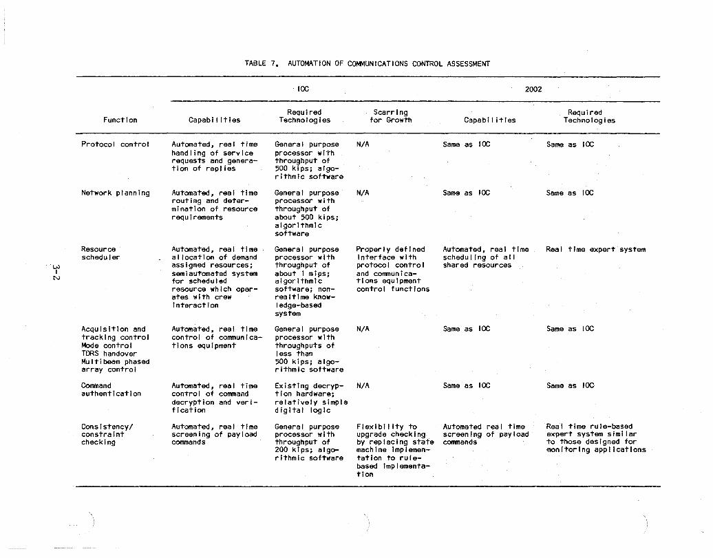
W I
N
FuncTion
ProTocol control
Network planning
Resource scheduler
Acquisition and tracking conTrol Mode control TORS handover MulTibeam phased array control
Command authenTicaTion
Consistency/ consTrainT checking
TABLE 7. AUTOMATION OF COMMUNICATIONS CONTROL ASSESSMENT
Capabi I Ities
AutomaTed, real time handling of service requesTs and generation of replies
AutomaTed, real time rouTing and deTerminaTion of resource requirements
AutomaTed, real time allocaTion of demand assigned resources; semiauTomaTed system for schedu I ed resource which operates with crew Interaction
AUTomaTed, real time control of communications equipment
AUTomaTed, real time control of command decryption and verification
AutomaTed, real time screening of payload commands
IOC
Required Scarring Technologies for Growth
General purpose N/A processor with ThroughpuT of 500 kips; algorithmic sofTware
General purpose N/A processor WiTh ThroughpuT of abouT 500 kips; algorithmic software
General purpose processor WiTh throughpuT of abouT 1 mips; algorithmic sofTware; nonrea I time knowledge-based sysTem
General purpose processor with throughpuTs of less than 500 kips; algorithmic software
Properly defined interface WiTh protocol conTrol and communications equipmenT conTrol functions
N/A
Existing decryp- N/A Tlon hardware; relaTively simple digiTal logic
General purpose processor with throughpuT of 200 kips; algoriThmic sofTware
Flexibility to upgrade checking by replacing state machine implementaTion TO rulebased Implementation
2002
Capabi I iTles
Same as IOC
Same as IOC
AUTomaTed, real time schedul ing of all shared resources
Same as IOC
Same as IOC
AutomaTed real time screening of payload commands
Required Technologies
Same as IOC
Same as IOC
Real Time experT system
Same as IOC
Same as IOC
Real time rule-based expert system similar TO Those designed for monitoring applications
function. Procedure-oriented software written in a standard algorithmic language would be appropriate for this application. Sufficient margins must be provided on processor throughput and memory to assure that further growth in the types of communications services supported by the protocol control can be accommodated.
Network Planning. The network planning function will require general purpose processing for the planning of communication routes from specified source to specified destination and the selection of appropriate resources (encoders, compressors, encryptors, modulators, demodulators, decryptors, decompressors, decoders, etc.). As in the case of protocol control, existing processor and software technologies are sufficient to implement the functions at IOC. Of course, the hardware and software implementing this function for the IOC space station must be capable of accommodating the new links and resources of the evolving space station system.
Resource Planning. User's requests for communications services in the automation concept included requests for future scheduleing of such services as video and high data rate communications. The scheduling and coordination of such requests with associated requests for other station resources such as electrical power and thermal dissipation capacity will probably require a sophisticated system capable of real time synthesis of scheduling plans.
The technology status for expert systems for planning and scheduling is indicated by three developmental systems: 1) the Knowledge-Based English Enquiry Crew Activity Planner (KNEECAP) that is under development at MITRE, 2) JPL's Deviser, and 3) a satellite tasking and scheduling system, under development at Hughes.
MITRE's KNEECAP is an adaptation of an existing knowledge-based system (KNOBS), developed by MITRE under sponsorship of the Air Force's Rome Air Development Center. The KNOBS system was developed to provide checking of air mission plans. Its successor KNEECAP is intended as a demonstration of an onboard expert system for assisting with crew activity planning for the space shuttle and ultimately the space station.
The system is being designed to allow a crew member to define an activity and place it on current activity plans. It will check for three types of planning constraints:
1) The availability of time on the current timeline to accommodate the new activity;
2) Special constraints pertaining to the particular activity (e.g., orbital position windows, sunlight/daylight conditions); and
3) Overall timeline constraints (e.g., required frequency of periodic activities, required ordering of sequential activities).
3-3
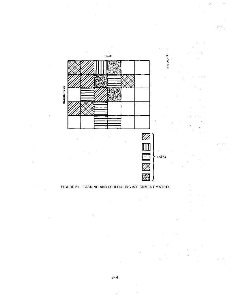
C/) w U 0: ::> o C/) W 0:
TIME
TASKS
FIGURE 21. TASKING AND SCHEDULING ASSIGNMENT MATRIX
3-4

Recent activities in the KNEECAP development include the transfer of the system from a shared mainframe to a single-user LISP machine (a Symbolics 3600) with a software translation from INTERLISP to ZET ALISP and the incorporation of a high resolution, bit-mapped display, a window system, and a mouse-controlled pointer to create a more comfortable and efficient user interface.
Deviser was developed by JPL for the planning and scheduling of the operations of science instruments on autonomous unmanned spacecraft. Goals are defined as sets of activities of varying duration, some of which may be performed in parallel within specified time windows. The capabilities of Deviser will be demonstrated in the planning for the Voyager encounter with Uranus.
Recently, development of an expert system for tasking and scheduling in satellite operations has begun at Hughes. In a simplified form, the approach selected to this problem can be described as the assignment of volumes in a space with axes representing resources and time. With time represented as a discrete variable, the problem can be reduced to that of the generation of an assignment matrix whose entries represent tasks that are to be scheduled (see Figure 21). The completion of a task requires particular resources for certain minimum durations with constraints on the time relationships of the resource assignments. Thus only limited combinations of resource assignments satisfy a task. In addition, tasks may have prioritization which varies with time.
An expert system is being developed which will synthesize such an assignment matrix, based on heuristic search or by construction using production rules, evaluating progress based on specified constraints on the relationships of resources and time for each task and on a defined evaluation criterion. The Hughes effort is currently in the initial design stage.
Complete automation of planning and scheduling will require a system that is significantly more complex than the developmental systems described above. The increase in complexity is likely to be at least two orders of magnitude, since the current developmental systems deal with far fewer resources in comparison with those of the space station. Moreover, the developmental expert systems require interaction with operators. Significant development in expert system technology will be required before expert systems are available which can operate in real time and without assistance from operators.
In summary, a resource scheduling system that works interactively with the crew should be technically feasible for use onboard the space station at IOC. The feasibility of a totally automated scheduler with sufficient efficiency and reliability is very doubtful for that time frame.
Communications Equipment Control. The communications equipment control function can be implemented with existing processor and software technologies. Functions similar to acquisition and pointing control and to mode control have been implemented in current and past spacecraft designs. No multibeam phased array systems are currently used in
3-5
space, therefore the multibeam phased array control function will be a new development. However, there are no obvious technical difficulties in the development of processing for that control. The absence of multibeam phased array systems for space is primarily due to hardware cost and packaging difficulties.
The TORS handover function will be performed by ground operation in the space shuttle system after the second TORS is launched. However, totally automated implementation of that function onboard the space station is feasible. The station will have the capability in its guidance, navigation and control (GNC) system for prediction of relative positions of spacecraft, such as free flyers and TORS, using stored prediction coefficients. Automated TORS handover is expected to require a processor with a throughput of about 200 kips to process position information from the GNC system and to generate command sequences to antennas and other communications hardware.
Payload Command Processing. The command authentication function of payload command processing can be implemented with hardware based on existing designs and devices for decryption based on the National Bureau of Standards' Data Encryption Standard (DES). The DES standard is probably sufficient for IOC applications. However, the length of the key variable (64 bits) may be too short to provide high assurance of security. Thus, the command authentication function should be implemented in a manner that enables upgrading of the encryption/decryption approach.
The implementation of the constraint/consistency checking function should be based on rules to provide ease of maintenance and modification. Its implementation would then be similar to that of an expert system for monitoring. The system would monitor the state of the station and screen payload commands based on its knowledge of the station state and the potential effects of each payload command.
Since it is unlikely that such a system would be technically feasible for IOC, a simpler implementation based on a state representation of station status should be adopted. This approach can be implemented with standard processors and standard software approaches. However, it will likely be difficult to maintain and modify since the definition of the states will represent the result of various analyses of the interactions among subsystems and payloads.
3.1.2 Other Communications-Related Technologies
Three technology areas that potentially offer significant automation capabilities are reviewed in this subsection. The digital telephony system offers approaches, standards, and services that can lead to automated communications for the space station with relatively low development costs and high flexibility for internetting with commercial communications systems. Speech recognition and synthesis can provide versatile man/machine interactions. The last, data compression/decompression, is essential for efficient use of precious communications resources.
3-6
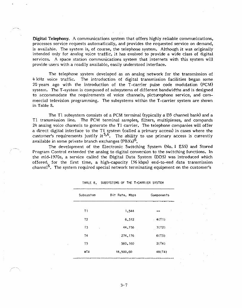
Digital Telephony. A communications system that offers highly reliable communications, processes service requests automatically, and provides the requested service on demand, is available. The system is, of course, the telephone system. Although it was originally intended only for analog voice traffic, it has evolved to provide a wide class of digital services. A space station communications system that internets with this system will provide users with a readily available, easily understood interface.
The telephone system developed as an analog network for the transmission of 4 kHz voice traffic. The introduction of digital transmission facilities began some 20 years ago with the introduction of the T -carrier pulse code modulation (PCM) system. The T -system is composed of subsystems of different bandwidths and is designed to accommodate the requirements of voice channels, picturephone service, and commercial television programming. The subsystems within the T -carrier system are shown in Table 8.
The Tl subsystem consists of a PCM terminal (typically a 03 channel bank) and a T 1 transmission line. The PCM terminal samples, filters, multiplexes, and compands 24 analog voice channels to generate the T 1 carrier. The telephone companies will offer a direct digital interface to the T 1 system (called a primary access) in cases where the customer's requirements justify it5,6. The abili~ to use primary access is currently available in some private branch exchanges (PBXs) •
The development of the Electronic Switching System (No. 1 ESS) and Stored Program Control extended the analog to digital conversion to the switching functions. In the mid-1970s, a service called the Digital Data System (DDS) was introduced which offered, for the first time, a high-capacity (56 kbps) end-to-end data transmission channel6. The system required special network terminating equipment on the customer's
TABLE 8. SUBSYSTEMS OF THE T-CARRIER SYSTEM
Subsystem Bit Rate, Mbps Components
T1 1.544
T2 6.312 4(Tl )
T3 44.736 7(T2)
T4 274.176 6{T3)
T5 560.160 2{T4)
WT4 18,500.00 48(T4)
3-7
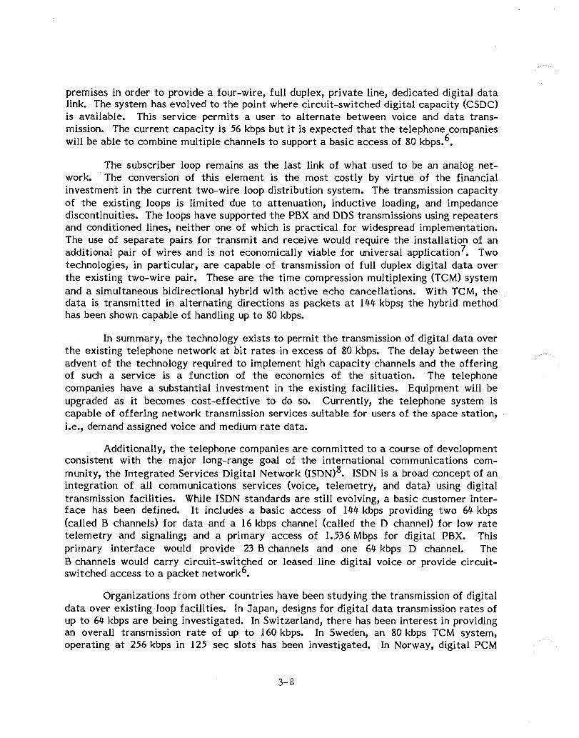
premises in order to provide a four-wire, full duplex, private line, dedicated digital data link. The system has evolved to the point where circuit-switched digital capacity (CSDC) is available. This service permits a user to alternate between voice and data transmission. The current capacity is 56 kbps but it is expected that the telephone companies will be able to combine multiple channels to support a basic access of 80 kbps. 6•
The subscriber loop remains as the last link of what used to be an analog network. The conversion of this element is the most costly by virtue of the financial investment in the current two-wire loop distribution system. The transmission capacity of the existing loops is limited due to attenuation, inductive loading, and impedance discontinuities. The loops have supported the PBX and DDS transmissions using repeaters and conditioned lines, neither one of which is practical for widespread implementation. The use of separate pairs for transmit and receive would require the installation of an additional pair of wires and is not economically viable for universal application7• Two technologies, in particular, are capable of transmission of full duplex digital data over the existing two-wire pair. These are the time compression multiplexing (TCM) system and a simultaneous bidirectional hybrid with active echo cancellations. With TCM, the data is transmitted in alternating directions as packets at 144 kbps; the hybrid method has been shown capable of handling up to 80 kbps.
In summary, the technology exists to permit the transmission of digital data over the existing telephone network at bit rates in excess of 80 kbps. The delay between the advent of the technology required to implement high capacity channels and the offering of such a service is a function of the economics of the situation. The telephone companies have a substantial investment in the existing facilities. Equipment will be upgraded as it becomes cost-effective to do so. Currently, the telephone system is capable of offering network transmission services suitable for users of the space station, i.e., demand assigned voice and medium rate data.
Additionally, the telephone companies are committed to a course of development consistent with the major long-range goal of the international communications community, the Integrated Services Digital Network (ISDN)8. ISDN is a broad concept of an integration of all communications services (voice, telemetry, and data) using digital transmission facilities. While ISDN standards are still evolving, a basic customer interface has been defined. It includes a basic access of 144 kbps providing two 64 kbps (called B channels) for data and a 16 kbps channel {called the D channel} for low rate telemetry and signaling; and a primary access of 1.536 Mbps for digital PBX. This primary interface would provide 23 B channels and one 64 kbps D channel. The B channels would carry circuit-switched or leased line digital voice or provide circuitswitched access to a packet network6•
Organizations from other countries have been studying the transmission of digital data over existing loop facilities. In Japan, designs for digital data transmission rates of up to 64 kbps are being investigated. In Switzerland, there has been interest in providing an overall transmission rate of up to 160 kbps. In Sweden, an 80 kbps TCM system, operating at 256 kbps in 125 sec slots has been investigated. In Norway, digital PCM
3-8

hybrid transmission rates up to 80 kbps have been analyzed. In Great Britain, Germany, France, and Italy, discussion have begun on high rate digital transmission9•
It seems clear that an ISDN compatible network would provide a convenient, standard access for potential space station users.
Speech Recognition and Synthesis. The automated communications system provides for command and control by a voice input/output (I/O) system. Interaction between man and machine by speech communications has many advantages over other methods (e.g., visual display output and keyboard input), especially when the user is engaged in tasks such as teleoperations, requiring intense hand and eye involvement. Table 9 from Woodard and Cupples lO in the IEEE Communications Magazine, summarized the advantages and disadvantages of speech I/O for command and control. Although Woodard and Cupples' article addressed military applications, their conclusions are totally applicable to space station operations. They conclude that "speech offers the most natural, and potentially the most accurate and fastest mode of communications, but is susceptible to environmental interference." An additional limitation of speech recognition in particular is the degraded performance under conditions different from that of the training period. Performance of the system under conditions that place the user in emotional stress remains to be sufficiently investigated.
Commercial automatic speech recognition systems for isolated words with vocabularies of up to 1000 words per speaker, real time or near real time (fractions of a second) performance, and accuracies of up to 99 percent or better are available today at very high cost. (See, for example, the survey by Kaplan 11.) Laboratory systems for connected speech recognition with similar vocabulary sizes, branching factors (average number of alternative words that can follow an input word) of several tens of words, and accuracies greater than 95 percent have been reported 11.
Automatic speech recognition systems with far greater capabilities will be feasible as new very large scale integrated (VLSI) circuits for signal processing, general purpose processing, and associative memory are developed.
Speech synthesis systems that are based on the encoding of a person's spoken words with an efficient storage technique, such as linear predictive coding, and playback of speech by simple concatenation are available today. The Texas Instruments "Show and Spell" toy is an example. More advanced systems, based on phonological and intonation rules, are being introduced?
Data Compression. The space station communications system must provide different forms of communications services to various users with many diverse requirements. These requirements encompass a spectrum of communications needs ranging from onboard crew member to crew member audio communications and teleconferencing systems with color video to telepresence systems with stereo vision capability. Each of these forms of communications has a unique data rate requirement. However, due to the limited amount of bandwidth, or in the case of digital transmission, the insufficient data
3-9

TABLE 9. ADVANTAGES AND DISADVANTAGES OF SPEECH I/O FOR COMMAND AND CONTROL
Advan~ages
Engineering
1. Can be faster than other modes of communications.
2. Can be more accurate than other modes of communications.
3. Compatible with existing communications systems, that is, telephones.
4. Can be more accurate in tasks currently performed by humans, that is, automatic speaker verification vs. identity verification by human visual inspection.
5. Can reduce manpower requirements.
6. Requires little panel space.
Psychological
1. Most natural form of human communications.
2. Best for group or team problem solving.
3. Universal (or nearly so) among humans.
4. Can reduce visual Information overload.
5. Increases in value when the human is engaged in activities requiring highly complex cognitive processing.
Physiological
1. Requires less effort and motor activity than other communications modes.
2. Frees hands and eyes and does not require physical contact with a transducer.
3. Permits multimodal operation.
4. Is feasible in a darkened environment.
5. Is omnidirectional and does not require direct line of sight.
6. Permits considerable operator mobility.
7. Contains information on identity and emotional state of speaker.
8. Contains information on physical state of the speaker.
9. Simultaneous communications with machines and humans are possible.
3-10

Table 9 (continued)
Disadvantages
Engineering
1. Competing acoustic signals may interfere with speech. These include noise, distortions, and competing talkers.
2. Physical conditions can change the acoustic characteristics of speech, that is, vibration, g-forces, and physical orientation of the speaker.
3. Unl ike typing, there is no permanent record of speech (unless explicitly recorded).
4. Microphones are required for speech input, and acoustic speakers are required for speech output.
Psychological
1. Speech is not private and may be observed and recorded by others.
2. Psychological changes (stress, for example) in the speaker may change his speech characteristics.
3. Synthetic speech output may interfere with other aural indicators.
Physiological
1. Fatigue can result from prolonged speaking, and this may change speech characteristics.
2. Physical ailments such as colds may change speech characteristics.
handling capability of the system for such enormous data rates, some forms of data compression are required. Table 10 shows the normal digital data rates for the various space station communications applications followed by the acceptable digital data rates of compressed data. For example, the uncompressed digital data rate of audio communications is normally 64 kbps. Applying the linear predictive coding (LPC) method of compression, a digital data rate of 2.4 kbps is acceptable for crew member to crew member communications. In applications where the movement is relatively slow (e.g., extravehicular activity) a useful compression method is to reduce the frame rate. Thus, instead of transmitting 30 frames/sec interlaced 2 to 1, an acceptable amount of information can be procured from 10 frames/sec interlaced 6 to 1.
Certain space station communications applications require improved picture resolution over that achievable using NTSC standards. Improved resolution is the goal of high definition video which is in the development stage today. An interim goal is the development of multiplexed analog component systems designed to enhance existing color television. Table 11 shows five black and white and color video systems that are
3-11
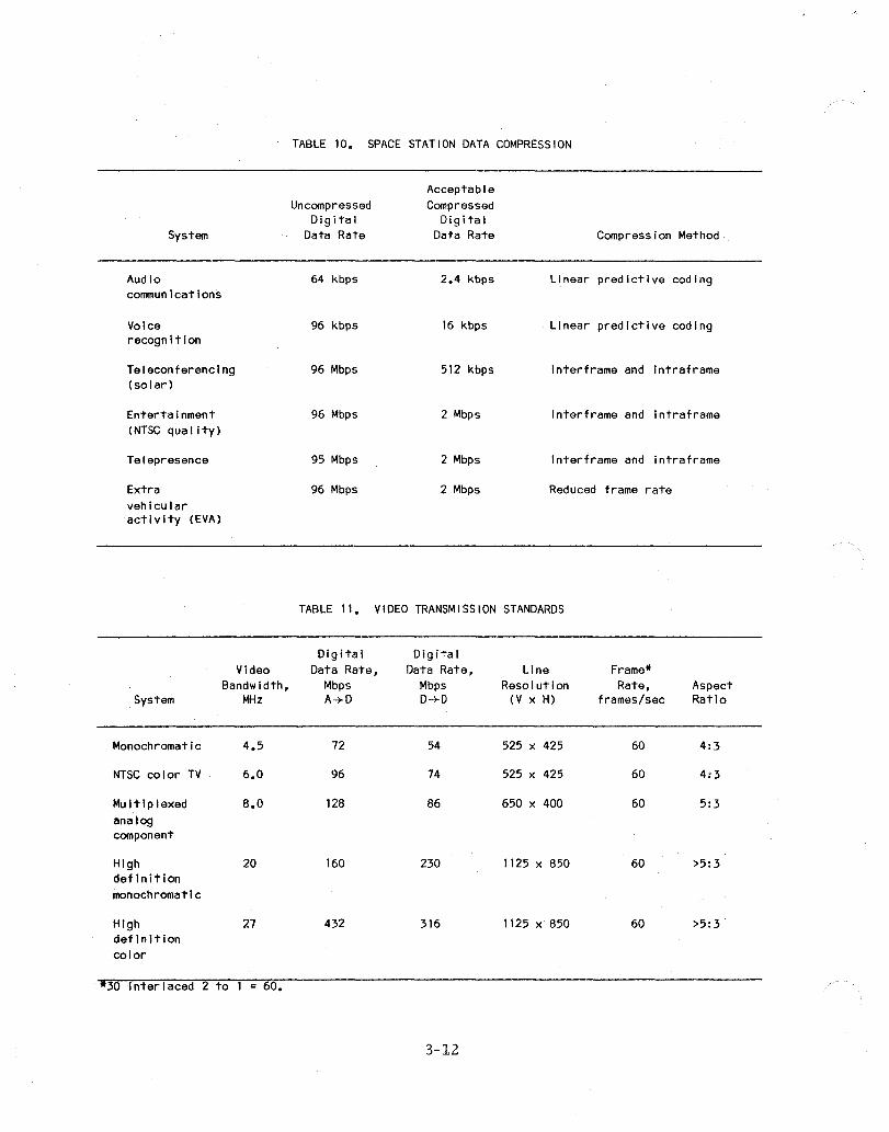
System
Audio communications
Voice recognition
Teleconferencing (solar)
Entertainment (NTSC qua I i ty )
Telepresence
Extra vehicular activity (EVA)
Video Bandwidth,
System MHz
Monochromatic 4.5
NTSC color TV 6.0
Multiplexed 8.0 analog component
High 20 definition monochromatic
High 27 definition color
*30 Interlaced 2 to 1 60.
TABLE 10. SPACE STATION DATA COMPRESSION
Acceptable Uncompressed Compressed
Digital Digital Data Rate Data Rate Compression Method
64 kbps 2.4 kbps Linear predictive coding
96 kbps 16 kbps Linear predictive coding
96 Mbps 512 kbps Interframe and intraframe
96 Mbps 2 Mbps I ntert rame and intraframe
95 Mbps 2 Mbps Interframe and intraframe
96 Mbps 2 Mbps Reduced frame rate
TABLE 11. VIDEO TRANSMISSION STANDARDS
Digital Digital Data Rate, Data Rate, Line Frame*
Mbps Mbps Resolution Rate, Aspect A-+D D-+D (V x H) frames/sec Ratio
72 54 525 x 425 60 4:3
96 74 525 x 425 60 4:3
128 86 650 x 400 60 5:3
160 230 1125 x 850 60 >5:3
432 316 1125 x 850 60 >5:3
3-12

either currently in operation or being developed. The analog bandwidth, digital data rate, line resolution, frame rate and aspect ratio is given for each video system. Two figures for the digital data rate of each system are given. The first data rate corresponds to an analog system which converts the signal to digital for transmission (AID conversion). The second data rate figure represents an all-digital system where all video information originates in digital form, where no AID conversion is required.
As studies in the robotics, teleoperations and telepresence fields progress, it is becoming apparent that high definition video is required. Data compression techniques become even more important in dealing with these extremely high data rates. For many applications, data compression of high resolution video defeats the purpose of high resolution. However, in cases where temporal displacements are not significant (e.g., slow moving EVA), implementing a compression technique such as that achieved by reducing the frame rate results in a very well-defined picture with small gaps in the movement. The question of whether or not this result is acceptable cannot be answered until the applications become better defined.
3.2 ELECTRICAL POWER AND THERMAL
The real time control of the power and thermal subsystems as demonstrated in battery recharge and reconditioning and thermal fluid loop control can be implemented using today's technology. The complications of power and thermal control for the space station beyond present spacecraft systems are increased average and peak bus powers, the enormous scale of the space station size resulting in larger transport distances, the extended mission life, the architectural and electronic complexity, and the presence of man onboard. These complications, however, suggest developments in engineering technology as opposed to advancements in automation.
To some degree, power and thermal load management can also be automated using today's technology to solve the problem of real time adaptive resource requests. The management of loads in an anticipative mode must interact with the global planning and scheduling system for all space station resources. Such a planning and scheduling system may require an expert system.
3.3 SYSTEM MONITORING AND CONTROL
Autonomous system monitoring and control offers significant payoffs in a space station environment. Due to the limited manpower available onboard, it is important that onboard personnel function at maximum efficiency. Automation of system monitoring and control serves to relieve the extensive manpower requirements of both ground and crew members needed for real time services.
For the space station, continuous telemetry and alarm monitoring by the crew is impractical since it is likely that only two onboard crew members with sufficient training
3-13

and knowledge will be responsible for system monitoring and fault recovery. Monitoring of telemetry on the ground is inconsistent with the goal of autonomous space station operation. Telemetry monitoring must be performed by automation onboard the station.
A comprehensive fault recovery system minimizes the number of malfunctions needing immediate operator attention. The system itself handles the great majority of malfunctions, allowing the onboard crew to perform other housekeeping tasks and payload support activities. The crew members will be on-call, free to perform other duties, but ready to respond instantly should an alarm occur.
Automation of fault recovery might begin with an automation of the malfunction procedures used by ground controllers and crew members in the space shuttle orbiter. An integrated system of software procedures or knowledge-based system is probably a reasonable approach to this automation. System monitoring software should be flexible enough to adapt to the changing requirements of the evolving space station.
Recent shuttle missions have averaged 20 malfunctions for a 7 day flight. The need to execute malfunction procedures two or three times a day is one reason so many real time ground operators are needed for shuttle operations. Another disturbing development realized during recent shuttle missions is the need to execute multiple mal-function procedures simultaneously. As yet, there is no set procedure for handling such a situation. Presently, crew members must use their own judgment to decide which of the procedures should be executed first, or whether steps should be alternated.
When current shuttle performance is extrapolated to the much more complex space station, it becomes clear that the present system, with its hundreds of written malfunction procedures, is inadequate. In order to handle the enormous number of possible failures, deal with multiple failures simultaneously, and maintain subsystem expertise over an extended mission lifetime, an automated fault detection and recovery system is needed.
It is clear that a large nonvolatile archival memory is necessary to store the massive amounts of information required to accommodate the above system. It has been estimated that memory on the order or a terabit (one trillion bits) may be required to store space station procedures, manuals, and engineering drawings in a computerized data archive. The most promising technology for such large storage is laser disk technology. Laser disks may prove to be ideal due to their ability to store graphical material and their resistance to poor operating conditions.
3-14
4. CONCLUSIONS AND RECOMMENDA nONS
Our review of subsystems and operations and development of an automation concept for the space station has lead us to six key recommendations for space station automation for enhanced user accommodation features and autonomous operations capability. These recommendations are:
1) That the space station communications system be designed as an end-to-end system that provides communications services between user end equipment;
2) That commercial digital telephony standards be incorporated in the space station communications systems;
3) That user requests for communication services be processed by an automated, real time system and that it provide for demand assignment of selected communications services;
4) That short-term planning and scheduling of space station resources be performed on the station and that it be automated at IOC to the extent necessary to provide demand assignment of selected communications services and crew assistance in scheduling;
5) That an automated payload command screening system be implemented;
6) That automatic speech recognition and synthesis be considered a basic mode of man/machine interaction for space station command and control during the design and development of the station;
7) That the data management system (DMS) and other subsystems of the space station be designed to accommodate fully automated fault detection, isolation, and recovery within the system monitoring function of the DMS. The automated system itself would be a growth capability.
These recommendations are intended to provide greater operational capabilities to payload users, to simplify the user interface with the space station system, and to provide the capability for autonomous station operations.
4-1

The first recommendation recognizes that use of the space station by customers and operators will be simplified by specifications of services for user end equipment. These standard services should be flexible enough to support a wide range of user needs. To develop such specifications, studies of the communication system during the definition phase should focus on communications as an end-to-end network. Such studies should be the communications counterparts to the Space Station Information System and Space Station Data System studies.
The second recommendation on the adoption of digital telephony standards supports the first and suggests an economical approach to the development of the end-toend communiations system. The very rapid development of digital telephony service is a development that NASA cannot ignore. Adoption of telephony standards' will enable simple interfacing to commercial communications systems for ground distribution of space station communications. The developing Integrated Services Digital Network (ISDN) standard defines a highly flexible digital service that will be supported by telephone and specialized communications services companies. The support of the ISDN service by the space station communications system will permit customers and operators to use ISDN-compatible equipment. Such equipment can be expected to be standard commercial equipment.
We recommend the real time processing of users requests for services to provide a responsive system that will provide access to available communications resources. The development of such service will require some additional hardware and software, but more significantly, it will require the development of an appropriate protocol that is compatible with the digital telephony approach.
Out recommendation for onboard, automated support of planning and scheduling recognizes that these functions are essential for the efficient automated operations of subsystems and payloads. Automated scheduling of communications resources is required for automated processing of user requests for communications services.
The fifth recommendation, for the automation of payload command screening, is intended to enable direct user control of his payload, subject only to the constraints enforced by the automated screening process. This recommendation is contingent on the development of an approach to the specification of the constraints that provide high assurance of safety and easy modification to accommodate new or modified payloads.
Although automated speech recognition technology is stH evolving and critical studies of its performance under conditions of stress for the station crew remain to be undertaken, it seems clear that automated speech recognition and synthesis systems will be extremely valuable for command and control by crew under demanding work loads. Recommendation 3 recognizes this potential. Any development of speech input/output (I/O) system for space station application must strive for a high degree of commonality in command syntax for the speech I/O system and the keyboard/display system.
4-2

The last recommendation is made because fault detection, isolation, and recovery must be automated onboard the space station if the station is to achieve autonomous operations capability. Although a fully automated system may not be technically feasible for IOC, a system concept for fault detection, isolation, and recovery must be developed during the definition phase. Subsystems must be designed to support automated fault detection, isolation, and recovery. Fault-tolerant processing must be provided onboard that space station to support the handllng of faults in subsystems.
The space station program can be an opportunity to advance automation technology in the United States. Among the candidate areas of automation examined in this study, two, planning/scheduling and fault detection, isolation, and recovery, seem to offer the greatest payoff in the context of enhanced industrial capability. The automation of both functions is likely to incorporate knowledge-based systems. Full automation of the functions is unlikely for space station IOC because real time knowledge-based systems for such complex function are unlikely to be available. The space station program can advance automation technology by developing the technology to support real time knowledge-based system.
4-3
5. REFERENCES
1) J.L. Anderson, "Progressive Autonomy," Proceedings of the AIAA/NASA Space Systems Technology Conference, June 1984, New York: AlA, pp 100-107
2) J. Mogilensky, et al., "Manned Spaceflight Activity Planning with KnowledgeBased Systems," Proceedings of the AIAA Computers in Aerospace IV Conference, October 1983, New York: AIAA, pp 224-227
3) S.A. Vere, Planning in Time: Windows and Durations for Activities and Goals, Research Report, November 1981, Pasadena, CA: Jet Propulsion Laboratory
4) J. Mogilensky, Private Communications, 24 August 1984.
5) G. Kim, "Transmission System Considerations for SDC," IEEE International Conference on Communications (Icc '82), Philadelphia, PA, June 13-17, 1982
6) R.M. Wienski, "Evolution to ISDN within the Bell Operating Companies," IEEE Communications Magazine, January 1984, pp 33-41
7) D. O'Shaughnessy, "Automatic Speech Synthesis," IEEE Communications Magazine, Vol. 21, No.9, December 1983, pp 26-34
8) G.S. Bhusri, "Considerations for ISDN Planning and Implementation," IEEE Communications Magazine, January 1984, pp 18-32
9) F .C. Kelcourse and E.H. Siegel, "Switched Digital Capacity: An Overview," IEEE Communications Magazine, January 1983, pp 29-31
10) J.P. Woodard and E.J. Cupples, "Selected Military Applications of Automatic Speech Recognition Technology," IEEE Communications Magazine, Vol. 21, No.9, December 1983, pp 35-41
11) G. Kaplan, "Words in Action: I," IEEE Spectrum, Vol. 17, No.6, June 1980, Piscataway, NJ: IEEE, pp 22-26
5-1
6. ANNOTATED BIBLIOGRAPHY
AUTONOMOUS OPERATIONS
1) J.L. Anderson, "Progressive Autonomy," Proceedings of the AlA A/NASA Space Systems Technology Conference, June 1984, New York: AIAA, pp. 100-107.
This article examines possible requirements and concepts for autonomous operations of the space station by reviewing the evolution of autonomy in the U.S. space programs.
2) J.L. Anderson, "Space Station Autonomy Requirements," Proceedings of the AIAA Computers in Aeerospace IV Conference, October 1983, New York: AIAA, pp. 162-170.
Anderson in this paper attempts to unify various definitions of autonomous operations and justifications for such capabilities.
3) A.O. Bridgeforth, "A New Approach to Implementing Spacecraft Power System Autonomy," Proceedings of the AIAA Computers in Aerospace IV Conference, October 1983, New York: AIAA, pp. 393-394.
This paper presents the application of a hierarchical processing architecture to a design of an autonomous spacecraft power subsystem.
4) M.H. Marshall and G.D. Low, Autonomous Spacecraft Maintenance Study Group, Final Report, JPL 80-88, February 1, 1981, Pasadena, CA: Jet Propulsion Laboratory.
This report describes the work of a 1980 workshop that brought together experts in autonomy concepts, spacecraft design, and fault-tolerant processing to develop a road map to develop autonomous operations capability for spacecraft.
6-1

5) R.R. Mullen, et al., A Comparison of Systems Concepts for Autonomous Operation of Spacecraft, Vol. I, Executive Overview, SCG 810517R, August 1981, EI Segundo, CA: Hughes Aircraft Company.
The report summarizes a study of alternative concepts for onboard electronics/ processing and the relative cost impact of autonomous operations of a communications satellite for each electronic/processing architectural approach. The study suggests significant considerations for autonomous capability that are also applicable to the space station.
6) R.L. Staehle, Technology for Space Station Autonomy, JPL Publication 84-45, 15 June 1984, Pasadena, CA: Jet Propulsion Laboratory.
This report presents results of an informal survey of experts in spacecraft automation to identify the most critical technology development areas for the IOC space station.
7) M.E. Thimlar, et al., "Future Space-Based Computer Processors," Aerospace America, March 1984, pp. 78-82.
This article is a brief review on processor technologies that are expected to be available for space applications over the next decade.
8) J.C. Tietz, Development of an Autonomous Video Rendezvous and Docking System, MCR-84-502, January 1984, Denver: Martin Marietta Aerospace.
This Martin Marietta report describes the results of a laboratory demonstration of the concepts that might be applied to an autonomous rendezvous and docking system for the space station.
9) P.R. Turner, "Autonomy and Automation for Space Station Housekeeping and Maintenance Functions," Proc. ASME Winter Meeting, 17 November 1983, New York: ASME.
This paper outlines a prospective functional architecture for allocation of autonomous and automated control of housekeeping and maintenance functions and discusses critical implementation issues.
10) P.R. Turner, Autonomous Spacecraft System Control Topics, Report D-1413, 15 March 1984, Pasadena, CA: Jet Propulsion Laboratory.
Definitions, costs and benefits, functional architecture expert systems, processing architecture, software, and implementation issues are discussed in the r.ontext of autonomous operations capability for spacecraft.
6-2
11) Proceedings of the Workshop on Overcoming Obstacles to Autonomy Implementation, November 1983, Pasadena, CA: Jet Propulsion Laboratory.
This document is the proceedings of a workshop of participants from industry and the Air Force to examine the difficulties in developing autonomous operations capabilities for spacecraft and to identify needed development activities.
PLANNING AND SCHEDULING
1) J. Mogilensky, et al., "Manned Spaceflight Activity Planning with KnowledgeBased Systems," Proceedings of the AIAA Computers in Aerospace IV Conference, October 1983, New York: AIAA, pp. 224-227.
In this paper, Mogilensky describes the goals, approaches, and background of the expert system, subsequently named KNEECAP--Knowledge-based English Enquiry Crew Activity Planner--under development at MITRE.
2) S.A. Vere, Planning in Time: Windows and Durations for Activities and Goals, Research Report, November 1981, Pasadena, CA: Jet Propulsion Laboratory.
This report describes the Deviser expert system for the planning and scheduling of science instruments on interplanetary spacecraft.
DIGITAL TELEPHONY SYSTEMS
1) G.S. Bhusri, "Considerations for ISDN Planning and Implementation," IEEE Communications MagaZine, Vol. 22, No.1, January 1984, pp. 18-32.
Bhusri reviews potential business and residential applications of ISDN, describes the interfacing of digital networks with the telephone system, and speculates on the future evolution of ISDN.
2) F.C. Kelcourse and E. H. Siegel, "Switched Digital Capacity: An Overview," IEEE Communications Magazine, Vol. 21, No.1, January 1983, pp. 29-31.
This article reviews switched digital capability which allows end-to-end circuitswitched 56 kbps data over the existing Bell System Network and discusses its role in the evolution of ISDN.
3) G. Kim, "Transmission System Consideration for SOC," Proc. IEEE International Conference on Communications, Philadelphia, 13-17 June 1982.
Kim reviews the impact of switched digital capability on the transmission equipment in the Bell System.
6-3

4) DeJ. Kostas, "Transition to ISDN--An Overview," IEEE Communications Magazine, Vol. 22, No.1, January 1984, pp. 11-17.
Kostas presents an overview of the Integrated Services Digital Network (ISDN) discussing its principles, capabilities, architecture, protocols, and standards in a special issue of the magazine.
5) S.G. Pitroda, "Telephones Go Digital," IEEE Spectrum, Vol. 16, No. 10, pp. 51-60.
This article provides a very readable review of the transition of the telephone system from analog to digital. A good bibliography on digital telephony is also presented.
6) R.M. Wienski, "Evolution to ISDN within the Bell Operating Companies," IEEE Communications Magazine, Vol. 22, No.1, January 1984, pp. 33-41.
This paper describes the proposed evolution of the former Bell Operating Companies' telecommunications networks to ISDN.
SPEECH RECOGNITION AND SYNTHESIS
1) H.L. Andrews, "Speech Processing," Computer, October 1984, Vol. 17, No.1 0, pp.315-324.
The status and direction of speech coding, recognition, and synthesis is reviewed.
2) G. Kaplan, "Words in Action: I," IEEE Spectrum, Vol. 17, No.6, June 1980, pp. 22-26.
Kaplan reviews the status of the technology for automatic speech recognition of isolated words and connected speech.
3) Y. Kato, "Words into Action III: a Commercial System," IEEE Spectrum, Vol. 17, No.6, June 1980, p. 29.
Kato presents a short description of Nippon Electric Company's work on a system that recognizes connected speech.
4) R. Reddy, "Words into Action II: a Task-Oriented System," IEEE Spectrum, Vol. 17, No.6, pp. 26-28.
Reddy describes the approach and capabilities of a connected speech recognition system developed at Carnegie Mellon University.
6-4
5) D. O'Shaughnessy, "Automatic Speech Synthesis," IEEE Communications Magazine, Vol. 21, No.9, December 1983, pp. 26-34.
This paper is a tutorial on the technical aspects of synthetic speech devices, their applications, and limitations.
6) J.P. Woodard and E.J. Cupples, "Selected Military Applications of Automatic Speech Recognition Technology," IEEE Communications Magazine, Vol. 21, No.9, December 1983, pp. 35-41.
This article reviews studies that have been performed in the potential uses of automatic speech recognition in military command and control applications.
VIDEO AND DATA COMPRESSION
1) R.K. Jurgen, "The Problems and Promises of High-Definition Television," IEEE Spectrum, December 1983, pp. 46-51.
Jurgen discusses the technological and economic barriers associated with highdefinition TV as well as the status of various on-going investigations in the field.
2) J. Roizen, "Montreux Symposium Spotlights Advanced Television Systems," IEEE Spectrum, December 1983, p. 46.
Roizen presents a short summary of the demonstrations of high-definition television at the Thirteenth International Television Symposium and Exhibition in Montreux, Switzerland, last May 28 to June 2.
3) J. Ishida, T. Nishizawa, and K. Kubota, "High Definition Television Broadcasting by Satellite," IEEE Transactions on Broadcasting, Vol. 28, No.4, December 1982, pp. 165-171.
This article describes different choices for signal format and transmission methods being investigated to make HDTV possible.
COMMUNICA nONS SYSTEMS
1) J.S. Rice and J.H. Ott, "Multibeam Phased Arrays - Application to SOC/Freeflyer Communication System," National Telecommunications Conference, 1982.
Rice and Ott present a discussion on the considerations in the use of multibeam phased arrays at 30 GHz followed by a discussion on the application of existing and envisioned phased array technology to meet space station communication link needs.
6-5
2) R.H. Cager, D.T. LaFlame, and L.C. Parode, "Orbiter Ku-Band Integrated Radar and Communications Subsystem," IEEE Transactions on Communications, Vol. 26, No. 11, November 1978, pp. 1604-1619.
This article describes the communications capabilities of the orbiter Ku-band subsystem which operates either as a radar system during rendezvous with other space vehicles or as a two-way communications system with the ground through the TDRSS.
3) M.I. Skolnik, Introduction to Radar Systems, McGraw-Hill, Inc., 1980 edition.
Skolnik includes in this book on radar systems several sections on phased array antenna systems and also discusses implementation of computer control to these phased array systems.
6-6

End of Document