automation systems s7-300, et 200m ex i/o modules · s7-300, et 200m ex i/o modules manual, edition...
TRANSCRIPT

SIMATIC Automation systems S7-300, ET 200M Ex I/O Modules
______________
______________________________________________________________________
Preface
Mechanical Configuration of an Automation System with SIMATIC S7 Ex Modules
1
SIMATIC S7 Ex Digital Modules
2SIMATIC S7 Ex Analog Modules
3SIMATIC S7 HART Analog Modules
4
Certificates A
Standards and licenses B
SIMATIC
Automation Systems S7-300, ET 200M Ex I/O Modules
Manual
Edition 06/2005 A5E00172008-08
This manual is part of the documentation package with the order number: 6ES7398-8RA00-8BA0
The following supplement is part of this documentation:
No. Designation Drawing number Edition 1 Product information A5E00201782-03 12/2004 2 Product information A5E00291373-02 02/2004 3 Product information A5E00336417-01 07/2004

Safety Guidelines This manual contains notices you have to observe in order to ensure your personal safety, as well as to prevent damage to property. The notices referring to your personal safety are highlighted in the manual by a safety alert symbol, notices referring only to property damage have no safety alert symbol. These notices shown below are graded according to the degree of danger.
Danger
indicates that death or severe personal injury will result if proper precautions are not taken.
Warning
indicates that death or severe personal injury may result if proper precautions are not taken.
Caution
with a safety alert symbol, indicates that minor personal injury can result if proper precautions are not taken.
Caution
without a safety alert symbol, indicates that property damage can result if proper precautions are not taken.
Notice
indicates that an unintended result or situation can occur if the corresponding information is not taken into account.
If more than one degree of danger is present, the warning notice representing the highest degree of danger will be used. A notice warning of injury to persons with a safety alert symbol may also include a warning relating to property damage.
Qualified Personnel The device/system may only be set up and used in conjunction with this documentation. Commissioning and operation of a device/system may only be performed by qualified personnel. Within the context of the safety notes in this documentation qualified persons are defined as persons who are authorized to commission, ground and label devices, systems and circuits in accordance with established safety practices and standards.
Prescribed Usage Note the following:
Warning
This device may only be used for the applications described in the catalog or the technical description and only in connection with devices or components from other manufacturers which have been approved or recommended by Siemens. Correct, reliable operation of the product requires proper transport, storage, positioning and assembly as well as careful operation and maintenance.
Trademarks All names identified by ® are registered trademarks of the Siemens AG. The remaining trademarks in this publication may be trademarks whose use by third parties for their own purposes could violate the rights of the owner.
Disclaimer of Liability We have reviewed the contents of this publication to ensure consistency with the hardware and software described. Since variance cannot be precluded entirely, we cannot guarantee full consistency. However, the information in this publication is reviewed regularly and any necessary corrections are included in subsequent editions.
Siemens AG Automation and Drives Postfach 48 48 90437 NÜRNBERG GERMANY
Order No.: A5E00172008-08 Edition 06/2005
Copyright © Siemens AG 2005. Technical data subject to change

S7-300, ET 200M Ex I/O Modules Manual, Edition 06/2005, A5E00172008-08 iii
Preface
Purpose of the manual This device manual will help you to
• plan,
• install,
• and operate a SIMATIC S7 ex module for an automation system in a hazardous area.
Basic knowledge required General knowledge of automation engineering is required to understand this manual.
You should be familiar with the fundamentals of explosion protection, with the identification of explosion-protected equipment and with the regulations regarding explosion protection.
Validity of the manual This device manual is valid for all the SIMATIC S7 ex modules listed by order number in the following table.
Table 1 S7-300 I/O modules
SIMATIC S7 ex module Order Number SM 321; DI 4 x NAMUR 6ES7321-7RD00-0AB0 SM 322; DO 4 x 24V/10mA 6ES7322-5SD00-0AB0 SM 322; DO 4 x 15V/20mA 6ES7322-5RD00-0AB0 SM 331; AI 8 x TC/4 x RTD 6ES7331-7SF00-0AB0 SM 331; AI 4 x 0/4...20mA 6ES7331-7RD00-0AB0 SM 332; AO 4 x 0/4...20mA 6ES7332-5RD00-0AB0 SM 331; AI 2 x 0/4...20mA HART 6ES7331-7TB00-0AB0 SM 332; AO 2 x 0/4...20mA HART 6ES7332-5TB00-0AB0
To find out which CPUs and IM 153-x versions you can use this module with, refer to the STEP 7 hardware catalog.

Preface
S7-300, ET 200M Ex I/O Modules iv Manual, Edition 06/2005, A5E00172008-08
Changes since the previous edition of the manual compared with the previous edition, this device manual includes the following changes.
• With the module SM 331; AI 2 x 0/4... 20 mA HART, technical data / additional measures and the 4th and 5th supplement of the EU special test certificate have been added.
• Small corrections carried out.
Approvals The SIMATIC S7300 product range has the following approvals: (see Appendix "Standards and Licenses")
CE marking The SIMATIC S7-300 product range meets the requirements and protection objectives of the following EU directives.
C-tick mark The SIMATIC S7-300 product range meets the requirements of the AS/NZS 2064 standard (Australia and New Zealand): (see Appendix "Standards and Licenses")
Standards The SIMATIC S7-300 product range meets the requirements and criteria of IEC61131-2, (see Appendix "Standards and Licenses")
Position in the information scheme Depending on the application, you will need the following documentation to understand this manual:
• S7-300: Hardware and Installation, CPU data, module specifications and instruction list
• ET 200M: Distributed I/O device
• Distributed I/O Devices S7-300, M7-300, ET 200M: Device manual
Guide The device manual "S7-300 automation systems, ET 200M Ex I/O Modules" contains technical descriptions of the individual modules.
The device manual covers the following subject areas:
• Chapter 1 explains the mechanical configuration of an automation system with SIMATIC S7 Ex modules
• Chapter 2 describes the SIMATIC S7 Ex digital modules
• Chapter 3 describes the SIMATIC S7 Ex analog modules
• Chapter 4 describes the SIMATIC S7 HART analog modules

Preface
S7-300, ET 200M Ex I/O Modules Manual, Edition 06/2005, A5E00172008-08 v
Recycling and disposal You can recycle the Ex I/O modules because they are made of low-toxicity materials. To recycle and disposal of your old device in an environmentally friendly way, please contact a company certified to deal with electronic waste.
Contact partner See product information Technical Support, Contact Partners and Training.
Training See product information Technical Support, Contact Partners and Training.
SIMATIC Technical Support See product information Technical Support, Contact Partners and Training.
Service & Support on the Internet See product information Technical Support, Contact Partners and Training.

Preface
S7-300, ET 200M Ex I/O Modules vi Manual, Edition 06/2005, A5E00172008-08

S7-300, ET 200M Ex I/O Modules Manual, Edition 06/2005, A5E00172008-08 vii
Table of contents Preface ...................................................................................................................................................... iii 1 Mechanical Configuration of an Automation System with SIMATIC S7 Ex Modules ............................... 1-1
1.1 Use............................................................................................................................................. 1-1 1.2 Fundamental Guidelines and Specifications.............................................................................. 1-1 1.3 The LK 393 line chamber........................................................................................................... 1-5 1.4 Configuration of an S7-300 with Ex I/O Modules....................................................................... 1-8 1.5 Configuration of an ET 200M with Ex I/O modules.................................................................. 1-11 1.6 Equipotential Bonding in Systems with Explosion Protection.................................................. 1-12 1.7 Wiring and Cabling in Ex Systems........................................................................................... 1-15 1.7.1 General information ................................................................................................................. 1-15 1.7.2 Marking of Cables and Lines of Intrinsically Safe Circuits....................................................... 1-17 1.7.3 Wiring and Cabling in Cable Bedding Made of Metal or in Conduits....................................... 1-17 1.7.4 Summary of Requirements of DIN EN 60079-14..................................................................... 1-18 1.7.5 Selecting the cables and wires in accordance with EN 60079-14........................................... 1-20 1.7.6 Types of cables........................................................................................................................ 1-20 1.7.7 Requirements of Terminals for Intrinsically Safe Type of Protection....................................... 1-23 1.8 Shielding and Measures to Counteract Interference Voltage .................................................. 1-24 1.8.1 Shielding .................................................................................................................................. 1-24 1.8.2 Equipment Shielding ................................................................................................................ 1-24 1.8.3 Line Shielding........................................................................................................................... 1-25 1.8.4 Measures to Counteract Interference Voltages ....................................................................... 1-28 1.8.5 The Most Important Basic Rules for Ensuring EMC ................................................................ 1-30 1.9 Lightning Protection ................................................................................................................. 1-31 1.9.1 Measures ................................................................................................................................. 1-31 1.9.2 External Lightning Protection/Shielding of Buildings ............................................................... 1-31 1.9.3 Creating distributed systems with S7-300 and ET 200M......................................................... 1-32 1.9.4 Shielding of Cables and Buildings ........................................................................................... 1-32 1.9.5 Equipotential Bonding for Lightning Protection........................................................................ 1-33 1.9.6 Overvoltage Protection ............................................................................................................ 1-33 1.9.7 Example of Lightning and Overvoltage Protection................................................................... 1-35 1.9.8 Lightning Strike ........................................................................................................................ 1-36 1.10 Installation Work in Hazardous Areas...................................................................................... 1-37 1.10.1 Safety Measures ...................................................................................................................... 1-37 1.10.2 Use of Ex Assemblies in Hazardous Zone 2 ........................................................................... 1-38 1.10.3 Use of Ex Assemblies in Hazardous Zone 1 ........................................................................... 1-39 1.11 Maintenance of Electrical Apparatus ....................................................................................... 1-42

Table of contents
S7-300, ET 200M Ex I/O Modules viii Manual, Edition 06/2005, A5E00172008-08
2 SIMATIC S7 Ex Digital Modules ............................................................................................................. 2-1 2.1 Chapter overview ....................................................................................................................... 2-1 2.2 Digital input module SM 321; DI 4 x NAMUR (6ES7321-7RD00-0AB0) ................................... 2-2 2.2.1 Features and technical specifications ........................................................................................ 2-2 2.2.2 Parameterization ........................................................................................................................ 2-7 2.2.3 Diagnostic messages ................................................................................................................. 2-9 2.2.4 Interrupts .................................................................................................................................. 2-12 2.3 Digital output module SM 322; DO 4 x 24V/10 mA (6ES7322-5SD00-0AB0) ......................... 2-14 2.3.1 Features and technical specifications ...................................................................................... 2-14 2.3.2 Parameterization ...................................................................................................................... 2-20 2.3.3 Diagnostic messages ............................................................................................................... 2-22 2.3.4 Interrupts .................................................................................................................................. 2-25 2.4 Digital output module SM 322; DO 4 x 15V/20 mA (6ES7322 5RD00-0AB0) ......................... 2-26 2.4.1 Features and technical specifications ...................................................................................... 2-26
3 SIMATIC S7 Ex Analog Modules ............................................................................................................ 3-1 3.1 Analog value representation ...................................................................................................... 3-1 3.1.1 Analog Value Representation of Analog Input and Output Values............................................ 3-1 3.1.2 Analog Representation for Measuring Ranges of Analog Inputs............................................... 3-2 3.1.3 Analog value representation for the voltage measuring ranges ................................................ 3-3 3.1.4 Analog value representation for the current measuring ranges................................................. 3-4 3.1.5 Analog value representation for measuring ranges of the resistance sensor............................ 3-5 3.1.6 Analog value representation for the standard temperature range ............................................. 3-6 3.1.7 Analog value representation for the climatic temperature range ............................................... 3-7 3.1.8 Analog value representation for the standard temperature range Ni 100.................................. 3-8 3.1.9 Analog value representation for the climatic temperature range Ni 100.................................... 3-9 3.1.10 Analog value representation for the temperature range type T ............................................... 3-10 3.1.11 Analog value representation for the temperature range type U............................................... 3-11 3.1.12 Analog value representation for the temperature range type E............................................... 3-12 3.1.13 Analog value representation for the temperature range type J................................................ 3-13 3.1.14 Analog value representation for the temperature range type L ............................................... 3-14 3.1.15 Analog value representation for the temperature range type K............................................... 3-15 3.1.16 Analog value representation for the temperature range type N............................................... 3-16 3.1.17 Analog value representation for the temperature range type R............................................... 3-17 3.1.18 Analog value representation for the temperature range type S............................................... 3-18 3.1.19 Analog value representation for the temperature range type B............................................... 3-19 3.1.20 Analog Value Representation for the Output Ranges of Analog Outputs................................ 3-20 3.2 General information on connection technology........................................................................ 3-21 3.3 Connecting transducers to analog inputs................................................................................. 3-22 3.4 Connecting thermocouples to the analog input SM 331; AI 8 x TC/4 x RTD........................... 3-25 3.5 Connection of resistance thermometers (e.g. Pt100) and resistance sensors ........................ 3-30 3.6 Using thermocouples ............................................................................................................... 3-31 3.7 Connecting voltage sensors..................................................................................................... 3-34 3.8 Connecting current sensors or measuring transducers to the analog inputs SM 331;
AI 4 x 0/4...20 mA..................................................................................................................... 3-35 3.9 Connecting Loads/Actuators to the Analog Output Module SM 332; AO 4 x 0/4...20 mA....... 3-36
Table of contents
S7-300, ET 200M Ex I/O Modules Manual, Edition 06/2005, A5E00172008-08 ix
3.10 Basic Requirements for the Use of Analog Modules ............................................................... 3-38 3.10.1 Conversion and Cycle Time of Analog Input Channels ........................................................... 3-38 3.10.2 Conversion, Cycle, Transient Recovery and Response Times of Analog Output Channels... 3-39 3.10.3 Parameters of Analog Modules................................................................................................ 3-40 3.10.4 Diagnostics of the Analog Modules ......................................................................................... 3-45 3.10.5 Interrupts of Analog Modules ................................................................................................... 3-50 3.10.6 Characteristics of Analog Modules .......................................................................................... 3-51 3.11 Analog input module SM 331; AI 8 x TC/4 x RTD (6ES7331-7SF00-0AB0) ........................... 3-53 3.12 Analog input module SM 331; AI 4 x 0/4...20 mA (6ES7331-7RD00-0AB0) ........................... 3-64 3.13 Analog input module SM 332; AO 4 x 0/4...20 mA (6ES7332-5RD00-0AB0) ......................... 3-71
4 SIMATIC S7 HART Analog Modules....................................................................................................... 4-1 4.1 Overview of the HART analog modules..................................................................................... 4-1 4.2 Product Overview for the Use of HART Analog Modules .......................................................... 4-2 4.3 Introduction to HART ................................................................................................................. 4-3 4.3.1 Definition of HART ..................................................................................................................... 4-3 4.3.2 HART functions.......................................................................................................................... 4-4 4.3.3 Application of HART................................................................................................................... 4-6 4.4 Guidelines for Installation and Operation................................................................................... 4-8 4.4.1 Example configuration ............................................................................................................... 4-8 4.4.2 Setting Up the HART Analog Module and Field Devices .......................................................... 4-9 4.4.3 Operating Phase of the HART Analog Module and Field Devices .......................................... 4-10 4.5 Parameters of HART Analog Modules..................................................................................... 4-12 4.6 Diagnostics and Interrupts of HART Analog Modules ............................................................. 4-14 4.6.1 Diagnostic Functions of HART Analog Modules...................................................................... 4-14 4.6.2 Interrupts of the HART Analog Modules .................................................................................. 4-16 4.7 HART analog input modules SM 331; AI 2 x 0/4...20 mA HART (6ES7331-7TB00-0AB0)..... 4-17 4.8 HART analog output module SM 332; AO 2 x 0/4...20 mA HART (6ES7332-5TB00-0AB0) .. 4-24 4.9 Data record interface ............................................................................................................... 4-30 4.9.1 Overview of the data record interface and user data............................................................... 4-30 4.9.2 Parameter Data Records ......................................................................................................... 4-31 4.9.3 Diagnostic data records ........................................................................................................... 4-33 4.9.4 HART Communication Data Records ...................................................................................... 4-35 4.9.5 Additional diagnostic data records........................................................................................... 4-39 4.9.6 Additional parameter data records........................................................................................... 4-42 4.9.7 User data interface - input area (read)..................................................................................... 4-43 4.9.8 Output Area (write)................................................................................................................... 4-44
A Certificates..............................................................................................................................................A-1 A.1 Overview of diagnostic functions ...............................................................................................A-1 A.2 Certificate of Conformity for Digital Input DI 4 x NAMUR ..........................................................A-2 A.2.1 EU Declaration of Conformity ....................................................................................................A-2 A.2.2 EU Declaration of Conformity for Digital Input DI 4 x NAMUR ..................................................A-5 A.3 Certificates of Conformity for Digital Output DO 4 x 24V/10 mA ...............................................A-6 A.3.1 EU Declaration of Conformity ....................................................................................................A-6 A.3.2 EU Declaration of Conformity for Digital Output DO 4 x 24V/10 mA.........................................A-9 A.4 Certificates of Conformity for Digital Output DO 4 x 15V/20 mA .............................................A-10

Table of contents
S7-300, ET 200M Ex I/O Modules x Manual, Edition 06/2005, A5E00172008-08
A.4.1 EU Declaration of Conformity...................................................................................................A-10 A.4.2 EU Declaration of Conformity for Digital Output DO 4 x 15V/20 mA .......................................A-13 A.5 Certificates of Conformity for Analog Input AI 8 x TC/4 x RTD................................................A-14 A.5.1 EU Declaration of Conformity...................................................................................................A-14 A.5.2 EU Declaration of Conformity for Analog Input AI 8 x TC/4 x RTD..........................................A-17 A.6 Certificates of Conformity for Analog Input AI 4 x 0/4...20 mA ................................................A-18 A.6.1 EU Declaration of Conformity...................................................................................................A-18 A.6.2 EU Declaration of Conformity for Analog Input AI 4 x 0/4...20 mA ..........................................A-21 A.7 Certificates of Conformity for Analog Output AO 4 x 0/4...20 mA............................................A-22 A.7.1 EU Declaration of Conformity...................................................................................................A-22 A.7.2 EU Declaration of Conformity for Analog Output AO 4 x 0/4...20 mA .....................................A-25 A.8 Certificates of Conformity for Analog Input AI 2 x 0/4...20 mA HART .....................................A-26 A.8.1 EU Declaration of Conformity...................................................................................................A-26 A.8.2 1. Amendment to analog input AI 2 x 0/4...20 mA HART ........................................................A-29 A.8.3 2. Amendment to analog input AI 2 x 0/4...20 mA HART ........................................................A-30 A.8.4 3. Amendment to analog input AI 2 x 0/4...20 mA HART ........................................................A-31 A.8.5 4. Amendment to analog input AI 2 x 0/4...20 mA HART ........................................................A-33 A.8.6 5. Amendment to analog input AI 2 x 0/4...20 mA HART ........................................................A-34 A.8.7 EU Declaration of Conformity for Analog Input AI 2 x 0/4...20 mA HART ...............................A-35 A.9 Certificates of Conformity for Analog Output AO 2 x 0/4...20 mA HART.................................A-36 A.9.1 EU Declaration of Conformity...................................................................................................A-36 A.9.2 1. Amendment to analog output AO 2 x 0/4...20 mA HART ....................................................A-39 A.9.3 EU Declaration of Conformity for Analog Output AO 2 x 0/4...20 mA HART...........................A-40
B Standards and licenses ..........................................................................................................................B-1 B.1 Standards and licenses..............................................................................................................B-1
Glossary ..................................................................................................................................... Glossary-1 Index................................................................................................................................................ Index-1 Tables
Table 1 S7-300 I/O modules ...................................................................................................................... iii Table 1-1 Cables and lines....................................................................................................................... 1-18 Table 1-2 Contents of the DIN VDE 0165702.91, continued ................................................................... 1-19 Table 1-3 Minimum cross sections of copper conductors in accordance with......................................... 1-20 Table 1-4 Types of cables ........................................................................................................................ 1-20 Table 1-5 Siemens cables for measurement and control to DIN VDE 0815............................................ 1-23 Table 1-6 Shielding of Ex lines................................................................................................................. 1-27 Table 1-7 Comparison of data for inductance and capacity..................................................................... 1-34 Table 1-8 Example of the comparison of data for inductance and capacity ............................................ 1-34 Table 1-9 Safety Measures ...................................................................................................................... 1-38 Table 1-10 Working on systems to type of protection: EEx de [ib] T5 .. T6 ............................................... 1-41 Table 2-1 Static and dynamic parameters of SM 321; DI 4 x NAMUR ...................................................... 2-7 Table 2-2 Allocation of 4 digital input channels to the 4 channel groups of SM 321; DI 4 x NAMUR........ 2-8 Table 2-3 Parameters of SM 321; DI 4 x NAMUR ..................................................................................... 2-8 Table 2-4 Delay times of input signal for SM 321; DI 4 x NAMUR............................................................. 2-9 Table 2-5 Diagnostic messages of SM 321; DI 4 x NAMUR.................................................................... 2-10

Table of contents
S7-300, ET 200M Ex I/O Modules Manual, Edition 06/2005, A5E00172008-08 xi
Table 2-6 Diagnostic messages as well as their causes and corrective measures in SM 321; DI 4 x NAMUR.......................................................................................................................... 2-11
Table 2-7 Dependencies of the input values for CPU operating status and supply voltage L+ of SM 321; DI 4 x NAMUR........................................................................................................... 2-13
Table 2-8 Static and dynamic parameters ............................................................................................... 2-20 Table 2-9 Allocation of the 4 channels to the 4 channel groups of SM 322; DO 4 x 24V/10 mA and
SM 322; DO 4 x 15V/20 mA..................................................................................................... 2-21 Table 2-10 Parameters of SM 322; DO 4 x 24V/10 mA and SM 322; DO 4 x 15V/20 mA ........................ 2-21 Table 2-11 Parameters of SM 322; DO 4 x 24V/10 mA and SM 322; DO 4 x 15V/20 mA ........................ 2-23 Table 2-12 Diagnostic messages as well as their corrective measures at SM 322;
DO 4 x 24V/10 mA and SM 322; DO 4 x 15V/20 mA .............................................................. 2-24 Table 2-13 Dependencies of output values on the CPU operating status and supply voltage L+ of
SM 322; DO 4 x 24V/10 mA and SM 322; DO 4 x 15V/20 mA................................................ 2-25 Table 3-1 Characteristics of Analog Modules ............................................................................................ 3-1 Table 3-2 Representation of the smallest stable unit of the analog value ................................................. 3-2 Table 3-3 Representation of the digitized measured value of an analog input module
(voltage measuring ranges) ....................................................................................................... 3-3 Table 3-4 Representation of the digitized measured value of analog input module SM 331;
AI 4 x0/4...20 mA and AI 2 x 0/4...20 mA HART........................................................................ 3-4 Table 3-5 Representation of the digitized measured value of an analog input module
(resistance sensor) .................................................................................................................... 3-5 Table 3-6 Representation of the digitized measured value of an analog input module
(temperature range, standard; Pt 100, Pt 200) .......................................................................... 3-6 Table 3-7 Representation of the digitized measured value of an analog input module
(climatic temperature range; Pt 100, Pt 200) ............................................................................. 3-7 Table 3-8 Representation of the digitized measured value of an analog input module
(standard temperature range, Ni 100) ....................................................................................... 3-8 Table 3-9 Representation of the digitized measured value of an analog input module
(climatic temperature range, Ni 100) ......................................................................................... 3-9 Table 3-10 Representation of the digitized measured value of an analog input module
(temperature range, type T) ..................................................................................................... 3-10 Table 3-11 Representation of the digitized measured value of an analog input module
(temperature range, type U)..................................................................................................... 3-11 Table 3-12 Representation of the digitized measured value of an analog input module
(temperature range, type E)..................................................................................................... 3-12 Table 3-13 Representation of the digitized measured value of an analog input module
(temperature range, type J) ..................................................................................................... 3-13 Table 3-14 Representation of the digitized measured value of an analog input module
(temperature range, type L) ..................................................................................................... 3-14 Table 3-15 Representation of the digitized measured value of an analog input module
(temperature range, type K)..................................................................................................... 3-15 Table 3-16 Representation of the digitized measured value of an analog input module
(temperature range, type N)..................................................................................................... 3-16 Table 3-17 Representation of the digitized measured value of an analog input module
(temperature range, type R)..................................................................................................... 3-17 Table 3-18 Representation of the digitized measured value of an analog input module
(temperature range, type S)..................................................................................................... 3-18 Table 3-19 Representation of the digitized measured value of an analog input module
(temperature range, type B)..................................................................................................... 3-19 Table 3-20 Representation of analog output range of analog output modules (current output ranges).... 3-20
Table of contents
S7-300, ET 200M Ex I/O Modules xii Manual, Edition 06/2005, A5E00172008-08
Table 3-21 Parameters of the Analog Input Module SM 331; AI 8 x TC/4 x RTD ..................................... 3-41 Table 3-22 Parameters of the analog input module SM 331; AI 4 x 0/4...20 mA....................................... 3-43 Table 3-23 Parameters of the analog output module SM 332; AO 4 x 0/4...20 mA................................... 3-44 Table 3-24 Diagnostic messages of the analog input modules SM 331; AI 8 x TC/4 x RTD,
AI 4 x 0 / 4...20 mA and AI 2 x 0/4...20 mA HART................................................................... 3-46 Table 3-25 Diagnostic messages of the analog input modules SM 331; AI 8 x TC/4 x RTD,
AI 4 x 0 / 4...20 mA and AI 2 x 0/4...20 mA HART - their possible causes of fault and corrective measures................................................................................................................. 3-47
Table 3-26 Diagnostic message of the analog output module SM 332; AO 4 x 0/4...20 mA..................... 3-48 Table 3-27 Diagnostic messages of analog output module SM 332; AO 4x0/4...20 mA and their
possible causes and corrective measures ............................................................................... 3-49 Table 3-28 Dependencies of analog input/output values on the CPU operating status and the
supply voltage L+ ..................................................................................................................... 3-51 Table 3-29 Characteristics of analog modules dependent on the position of analog input value in
value range .............................................................................................................................. 3-52 Table 3-30 Characteristics of analog modules dependent on position of analog output value in
value range .............................................................................................................................. 3-52 Table 3-31 Module view and block diagram of SM 331; AI 8 x TC/4 x RTD.............................................. 3-55 Table 3-32 Connectable thermocouples and thermal resistors ................................................................. 3-57 Table 3-33 Allocation of analog input channels of the SM 331; AI 4 x 0/4...20 mA to channel groups ..... 3-67 Table 3-34 Measuring ranges for 2-wire and 4-wire transducers .............................................................. 3-67 Table 3-35 Allocation of 4 channels to 4 channel groups of the SM 332; AO 4 x 0/4...20 mA .................. 3-73 Table 3-36 Output ranges of the analog output module SM 332; AO 4 x 0/4...20 mA .............................. 3-74 Table 4-1 Examples of HART parameters ................................................................................................. 4-5 Table 4-2 Examples of universal commands ............................................................................................. 4-5 Table 4-3 Examples of common-practice commands ................................................................................ 4-6 Table 4-4 Parameters of the analog input module SM 331; AI 2 x 0/4...20 mA HART............................ 4-12 Table 4-5 Parameters of the analog output module SM 332; AO 2 x 0/4...20 mA HART........................ 4-13 Table 4-6 Additional diagnostic messages for the analog input module SM 331; AI 2 x 0/4...20 mA
HART and the analog output module SM 332; AO 2 x 0/4...20 mA HART.............................. 4-14 Table 4-7 Additional diagnostic messages, possible causes of the errors, and corrective measures..... 4-15 Table 4-8 Local data in OB40................................................................................................................... 4-16 Table 4-9 Parameters of the analog input module SM 331; AI 2 x 0/4...20 mA HART............................ 4-18 Table 4-10 Output ranges of the analog output module SM 332; AO 4 x 0/4...20 mA .............................. 4-24 Table 4-11 Codes for the measurement type and measuring range for the HART analog input
module...................................................................................................................................... 4-31 Table 4-12 Codes for the measurement type and measurement range for the HART analog output
module...................................................................................................................................... 4-32 Table 4-13 HART group error displays....................................................................................................... 4-38 Table 4-14 HART protocol error during response from field device to module.......................................... 4-39 Table 4-15 Additional parameters of the HART analog modules............................................................... 4-42 Table B-1 Industrial use..............................................................................................................................B-3
S7-300, ET 200M Ex I/O Modules Manual, Edition 06/2005, A5E00172008-08 1-1
Mechanical Configuration of an Automation System
with SIMATIC S7 Ex Modules 11.1 1.1 Use
Overview The SIMATIC S7 Ex modules can be used in the systems:
• S7-300,
• ET 200M.
For installation purposes, you must therefore comply with the configuration guidelines as specified in the corresponding manuals. In addition, further reference guidelines for SIMATIC S7 Ex modules are provided in this chapter. These must be taken into consideration.
1.2 1.2 Fundamental Guidelines and Specifications
Note
Note Ex systems may only be installed by authorized personnel.
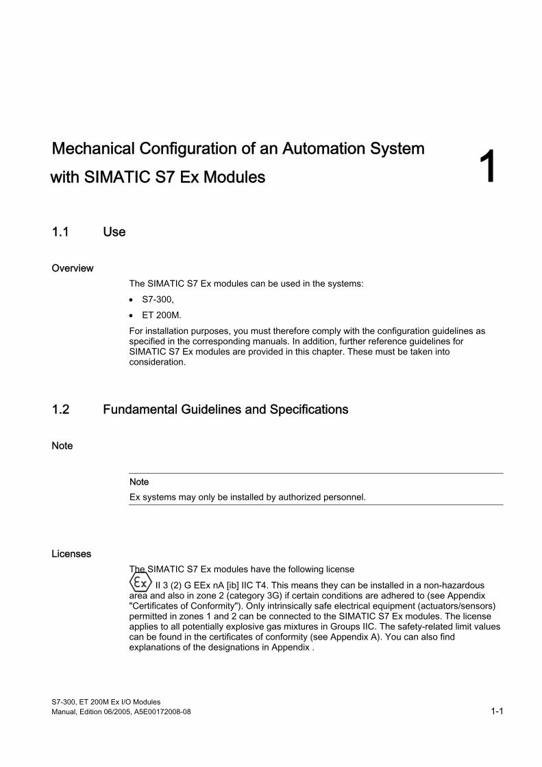
Licenses The SIMATIC S7 Ex modules have the following license
II 3 (2) G EEx nA [ib] IIC T4. This means they can be installed in a non-hazardous area and also in zone 2 (category 3G) if certain conditions are adhered to (see Appendix "Certificates of Conformity"). Only intrinsically safe electrical equipment (actuators/sensors) permitted in zones 1 and 2 can be connected to the SIMATIC S7 Ex modules. The license applies to all potentially explosive gas mixtures in Groups IIC. The safety-related limit values can be found in the certificates of conformity (see Appendix A). You can also find explanations of the designations in Appendix .

Mechanical Configuration of an Automation System with SIMATIC S7 Ex Modules 1.2 Fundamental Guidelines and Specifications
S7-300, ET 200M Ex I/O Modules 1-2 Manual, Edition 06/2005, A5E00172008-08
FM license The SIMATIC S7 Ex modules have the following FM licenses:
• Class I, Division 2, Group A, B, C, D Tx;
• Class I, Zone 2, Group IIC Tx
Therefore, the modules can be used in areas that contain volatile flammable liquids or flammable gasses which are normally within closed vessels or systems, from which they can only escape under abnormal operating or fault conditions. The license applies to all test gasses. A surface temperature no greater than 135 °C (T4) occurs at ambient temperatures of 60 °C.
Safe extra low voltage SIMATIC S7 Ex modules must be operated with a "safe functional extra low voltage". This means that only a voltage of U < 60 V must be applied to the modules even in the event of a fault. You will find more detailed information on the safe extra low voltage in, for example, the data sheets for the power supplies to be used.
All system components which can supply electrical energy in any form whatsoever must fulfill this condition. This includes in particular:
• the power supply module PS307. It fulfills this condition.
• the MPI interface. It fulfills this condition when all users operate with safe extra low voltage. SIMATIC automation systems and programming units also fulfill this condition.
• 115/230 V modules. Even if they are used in another cell or in another programmable controller they must feature safe extra low voltage on the system side (i.e. towards the backplane bus).
Any other power circuit (24V DC) used in the system must feature safe functional extra low voltage. Refer to the corresponding data sheets or consult the manufacturer.
Also bear in mind that sensors and actuators with external power supply may be connected to I/O modules. Also ensure a safe extra low voltage is used in this case. Even in the event of a fault, the process signal of a 24V digital module must never reach a fault voltage Um > 60V. This also applies to non-intrinsically safe components.
Note All voltage sources, e.g. 24V internal load voltage supplies, 24V external load voltage supplies, 5V bus voltage, must be electrically interconnected such that no voltage additions to the individual voltage sources can occur even under conditions with differences in potential - thus ensuring the fault voltage Um cannot be exceeded. You can achieve this, for example, by referring all voltage sources in the system to the functional ground. Also refer to the instructions provided in the relevant manuals (see Foreword) for this purpose. The maximum possible fault voltage Um in the system is 60V.

Mechanical Configuration of an Automation System with SIMATIC S7 Ex Modules 1.2 Fundamental Guidelines and Specifications
S7-300, ET 200M Ex I/O Modules Manual, Edition 06/2005, A5E00172008-08 1-3
Minimum thread measure A minimum thread measure of 50 mm must be maintained between connections with safe functional extra low voltage and intrinsically safe connections. In the process connector this is achieved by using a line chamber.
It is possible that the specified thread measure cannot be maintained in individual module components. In this case, you must use the spacer module DM 370, which you must set in such a way that it does not take up an address range. If you use the ET 200M Distributed I/O, you should observe the information regarding the configuration.
Also take care with regard to the wiring to ensure this specified spacing is maintained between intrinsically safe and non-intrinsically safe connections.
Combined use of Ex and non-Ex I/O modules Combined use is possible, however, the minimum thread measure between conductive parts of Ex and non-Ex modules must be maintained in all cases. As a rule, you must install DM 370 spacer modules between Ex and non-Ex modules. You must ensure strict separation of intrinsically safe and non-intrinsically safe conductors in the wiring system. They must be routed in separate cable ducts. A mixed operation is therefore not recommended.
Partition The Ex partition must be fitted to achieve the minimum thread measure of 50 mm between Ex and non-Ex modules when using the bus module of the active backplane bus.
Load current circuit The Ex sensors and Ex actuators are powered either by the Ex modules or by their own intrinsically safe power supply modules (e.g. 4-wire measuring transducers).
The Ex I/O modules receive their power supply via the backplane bus. The 24V DC load voltage input of the front connector is required for the power supply of the Ex sensors and the Ex actuators on the majority of modules.
Connecting Ex I/O modules The Ex I/O modules are configured in the same way as standard modules from left to right. Connect the Ex sensors and Ex actuators as well as the load voltage supply with the aid of the line chamber to the process connector which you then plug into the module.
Note If necessary, a safety assessment of this intrinsically safe power circuit should be carried out by an expert before a sensor or actuator is connected to an Ex module.

Mechanical Configuration of an Automation System with SIMATIC S7 Ex Modules 1.2 Fundamental Guidelines and Specifications
S7-300, ET 200M Ex I/O Modules 1-4 Manual, Edition 06/2005, A5E00172008-08
Replacing Ex I/O modules After being plugged in for the first time, the front connector adopts the module type coding set at the factory. This ensures that there can be no confusion with another type of module when replacing modules as the front connector can then no longer be unclipped, thus fulfilling explosion protection requirements. When replacing Ex modules, carry out the necessary steps in the order described below:
• Removal
1. Disconnect the L+ load voltage supply
2. Unplug the front connector
3. Remove the module
• Installation
1. Install the module
2. Plug in the front connector
3. Connect the L+ load voltage supply
See also Overview of diagnostic functions (Page A-1)
The LK 393 line chamber (Page 1-5)
Configuration of an S7-300 with Ex I/O Modules (Page 1-8)
Configuration of an ET 200M with Ex I/O modules (Page 1-11)

Mechanical Configuration of an Automation System with SIMATIC S7 Ex Modules 1.3 The LK 393 line chamber
S7-300, ET 200M Ex I/O Modules Manual, Edition 06/2005, A5E00172008-08 1-5
1.3 1.3 The LK 393 line chamber
Scope of application With the exception of the analog input module SM 331; AI 8 x Tc/4 x RTD, all Ex I/O modules require a 24V DC load voltage supply via the process connector. Safety isolation of this signal in order to maintain the minimum thread measure between Ex and non-Ex areas is achieved by using the LK 393 line chamber (Order No. 6ES7393-4AA00-0AA0). Process signals are carried downward while the 24V supply is routed upward in separate ducts.
Connecting the line chamber 1. The lines of the L+ and M connections are cut to the required length, their insulation is
stripped and wire end ferrules are fitted.
2. The conductor ends with the ferrules are passed through the openings in the LK 393 line chamber until they are flush with the fastening pins.
3. The conductors are then pressed into the guide ducts of the LK 393 line chamber and routed upward (secure with hot-melt adhesive if necessary).
4. The line chamber pre-assembled in this way is now inserted in the terminals of the front connector.
5. The wire end ferrules of L+ and M are screwed to the terminals 1 and 20 and the fastening pins to terminals 2 and 19.
This ensures a firm connection of the line chamber with the front connector, thus fulfilling explosion protection safety requirements.

Mechanical Configuration of an Automation System with SIMATIC S7 Ex Modules 1.3 The LK 393 line chamber
S7-300, ET 200M Ex I/O Modules 1-6 Manual, Edition 06/2005, A5E00172008-08
The following figs.illustrate the configuration.
1
2
3
4
Figure 1-1 Connecting the LK 393 line chamber
➀ Load voltage supply ➁ Process connector with screw-type terminal ➂ Ex (i) process cables ➃ Line chamber
1
2
L+
M
Figure 1-2 Inserting the load voltage connecting cables into the cable guides. Outside diameter of
the cables > 2 mm (view from below)
➀ Wire end ferrule ➁ Diameter > 2 mm

Mechanical Configuration of an Automation System with SIMATIC S7 Ex Modules 1.3 The LK 393 line chamber
S7-300, ET 200M Ex I/O Modules Manual, Edition 06/2005, A5E00172008-08 1-7
1
2
L+
M
Figure 1-3 Insert the L+ line in a loop in the line chamber. Outside diameter of the wires < 2 mm
(viewed from below)
➀ Wire end ferrule ➁ Diameter < 2 mm
Note Use Ex I/O modules which require a 24V load voltage exclusively with the LK 393 line chamber. It is necessary for ensuring the modules are used for their intended purpose.

Mechanical Configuration of an Automation System with SIMATIC S7 Ex Modules 1.4 Configuration of an S7-300 with Ex I/O Modules
S7-300, ET 200M Ex I/O Modules 1-8 Manual, Edition 06/2005, A5E00172008-08
Figure 1-4 LK 393 line chamber when connected
You can, of course, also use Ex I/O modules for non-intrinsically safe tasks. You will not need the line chamber in this case. However, you must then clearly and permanently cancel the Ex identification symbol. Subsequent use for Ex applications is no longer possible unless you return the module to the manufacturer for testing.
1.4 1.4 Configuration of an S7-300 with Ex I/O Modules
General information Physical isolation of non-Ex signals from Ex signals corresponds to the requirements with regard to the configuration of explosion-protected automation technology. If the minimum distance of 50 mm between bare connection terminals of Ex modules and bare connection terminals of non-Ex modules can not be maintained, a DM 370 spacer module (order number 6ES7370-0AA00-0AA0) must be fitted between these modules. Care must be taken to ensure that all automation systems are routed to a common ground.
This means:
• All earthing screws of the sectional rails must be referred to a common ground.
• The earthing clip of all CPUs must be locked in position.

Mechanical Configuration of an Automation System with SIMATIC S7 Ex Modules 1.4 Configuration of an S7-300 with Ex I/O Modules
S7-300, ET 200M Ex I/O Modules Manual, Edition 06/2005, A5E00172008-08 1-9
Spacing for arrangement on several subracks The following figure shows the spacing dimensions between the individual subracks as well as to adjacent items of apparatus, cable ducts, cabinet panels etc. for a two-tier S7-300 configuration.
1
2
3 40 mm
40 mm
40 mm
40 mm
a 200 mm+ a
IM 360
IM 361
Figure 1-5 Spacing dimensions for a two-tier S7-300 configuration
➀ L+ supply ➁ EX CABLE DUCT ➂ NON-EX (24V) CABLE DUCT
If you maintain these minimum spacing dimensions then:
• you will guarantee heat dissipation of the S7-300 modules
• you will have sufficient space to insert and remove the S7-300 modules
• you will have sufficient space for installing lines
Note If you use a shield support element, the specified dimensions apply as from the lower edge of the shield support element.

Mechanical Configuration of an Automation System with SIMATIC S7 Ex Modules 1.4 Configuration of an S7-300 with Ex I/O Modules
S7-300, ET 200M Ex I/O Modules 1-10 Manual, Edition 06/2005, A5E00172008-08
The L+/M lines on the Ex modules can be wired directly or via connection elements.
For direct wiring, route the L+/M lines from the cable duct (if a line chamber is used) directly to the terminals of the module front connector. You can route the Ex process lines directly from the front connector to the apparatus.
You can use commercially available clamp-type distributors for wiring via connection elements. You then have the option of disconnecting the L+/M supply lines module by module by means of a plug connector (see Fig. below).
1
2 3
4
5
Ex Ex
Figure 1-6 Wiring between L+/M lines and Ex modules via connecting elements
➀ Non Ex-cable duct ➁ Connecting Elements ➂ 15 mm top-hat rail ➃ Ex modules ➄ Ex cable duct
See also The LK 393 line chamber (Page 1-5)
Summary of Requirements of DIN EN 60079-14 (Page 1-18)

Mechanical Configuration of an Automation System with SIMATIC S7 Ex Modules 1.5 Configuration of an ET 200M with Ex I/O modules
S7-300, ET 200M Ex I/O Modules Manual, Edition 06/2005, A5E00172008-08 1-11
1.5 1.5 Configuration of an ET 200M with Ex I/O modules
ET 200M configurations on two subracks The Figure shows you two ET 200M configurations on two subracks. Place a DM370 dummy module between the IM153 and the first Ex I/O module in such a way that it doesn't occupy any address area. If you are using an active backplane bus, use an Ex partition (order number 6ES7195-1KA00-0XA0) instead of the dummy module.
3
4
1
2
SIMATIC ET 200M IM 153
DM 370
SIMATIC ET 200M IM 153
DM 370
IM 153PS
IM 153PS
Figure 1-7 Two subracks with ET 200M
➀ NON-EX CABLE DUCT ➁ EX CABLE DUCT ➂ S7-300 modules ➃ S7-300 modules

Mechanical Configuration of an Automation System with SIMATIC S7 Ex Modules 1.6 Equipotential Bonding in Systems with Explosion Protection
S7-300, ET 200M Ex I/O Modules 1-12 Manual, Edition 06/2005, A5E00172008-08
1.6 1.6 Equipotential Bonding in Systems with Explosion Protection
General Differences in potential can develop between the elements of electrical apparatus, connected with PE conductors, and conductive structural elements, piping etc. which does not pertain to the electrical apparatus. Sparks capable of causing ignition can be produced when implementing measures to bridge these differences in potential. To create potential equalization, conductive metal parts which are accessible and can be touched must be connected to each other and to the PE conductor. Equipotential bonding with the PE conductor can be best implemented at the distribution board. The cross section of the bonding conductor must be at least that of the PE conductor. In all other cases, the equipotential bonding conductor must have a cross section of at least 10 mm 2 of copper.
The Ex modules feature metallic isolation between the backplane bus and the I/O circuit; there is therefore no need for connection to the equipotential bonding conductor. Exception: when a connection to the EB conductor must be made for measurement purposes. Where lightning protection devices are required in the intrinsically safe circuit, they must be connected to the EB conductor at the same point as the shield of the intrinsically safe circuits.
Generally speaking, the measures described in EN 60079-14 should be used or adhered to.
Generally, cable racks must be incorporated throughout the earthing system.
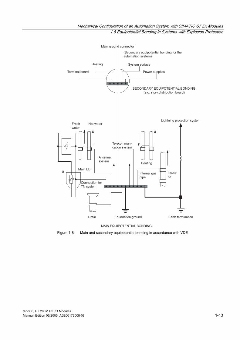
Equipotential bonding in a building In accordance with VDE 0100, Part 410 and Part 540 and DIN VDE 0185, equipotential bonding must be provided in every building and via the overall cabling of the automation system. If this is not the case, it must be installed.
Mechanical Configuration of an Automation System with SIMATIC S7 Ex Modules 1.6 Equipotential Bonding in Systems with Explosion Protection
S7-300, ET 200M Ex I/O Modules Manual, Edition 06/2005, A5E00172008-08 1-13
Main EB
Terminal board Power supplies
(Secondary equipotential bonding for the automation system)
SECONDARY EQUIPOTENTIAL BONDING(e.g. story distribution board)
Lightning protection systemHot water
Antenna system
Internal gas pipe
Connection for TN system
Telecommuni-cation system
Insula-tor
Fresh water
Earth terminationFoundation ground
MAIN EQUIPOTENTIAL BONDING
Drain
Heating
System surface
Main ground connector
Heating
Figure 1-8 Main and secondary equipotential bonding in accordance with VDE

Mechanical Configuration of an Automation System with SIMATIC S7 Ex Modules 1.6 Equipotential Bonding in Systems with Explosion Protection
S7-300, ET 200M Ex I/O Modules 1-14 Manual, Edition 06/2005, A5E00172008-08
Main equipotential bonding This interconnects the following conductive elements by the EB conductor on the EB bus: APA = 0.5 x APE main • PE conductor • Main ground conductor • Earth termination • Main water pipes • Main gas pipes • other metal piping systems • Metal structural elements of the building (if possible) • power and information system cables extending beyond the building, via lightning
conductor.
Additional equipotential bonding Connecting the following conductive elements by the EB conductor on the EB bus: • All "extraneous conductive elements" such as structural elements, supports, containers,
piping (these can themselves form EB conductors), APA = 0.5 x APEmax (A = cable cross section) from the distrib. board.
• Elements of stationary electrical apparatus which are accessible to simultaneous contact when it is connected to PEN (otherwise a PE connection suffices), APA = 0.5 x APE of both items of apparatus.
L1
PE
L2
L3
N
380 V
16 mm216 mm2
16 mm2
10 mm210 mm2
10 mm2 10 mm2
10 mm210 mm2
Equipment cabinet
Equipotential bonding (EB) bus
green/yellow
PE
bus
PE
bus
PE
bus
PE
bus
Power supply cabinet
Equipment cabinet with ex modules
Structural elements, containers, piping
To EB switch-room
Equipment cabinet with ex modules
Figure 1-9 Example of equipotential bonding for M&C systems
See also Measures (Page 1-31)

Mechanical Configuration of an Automation System with SIMATIC S7 Ex Modules 1.7 Wiring and Cabling in Ex Systems
S7-300, ET 200M Ex I/O Modules Manual, Edition 06/2005, A5E00172008-08 1-15
1.7 1.7 Wiring and Cabling in Ex Systems
1.7.1 General information
Measures Neither the electrical installation nor the required materials for this such as cables, lines and installation materials are subject to the special test procedure of ElexV with respect to their design. The responsibility of plant personnel or of an installation company for the proper installation of an Ex system is particularly high on account of the risk of explosion in the event of improper implementation.
General planning principles for cable routes are very similar to those for piping. At the drafting stage of installation plans and building layouts, areas with increased risk of fire and danger zones must be defined in accordance with ElexV and VbF. Cable and piping routes should preferably be arranged only in the area of low risk. Furthermore, accessibility and ease of maintenance must be ensured, also for subsequent expansion. With all types of switchroom, steps must be taken to ensure that the cable and line routes to the hazardous area are sealed so that they do not provide escape routes for hazardous gasses of vapors to the switchroom.
Note Laying cables in ducts in the floor should be avoided. There is the risk • of the penetration or the formation of potentially explosive gas / air mixtures and their uncontrolled
propagation, • penetration of corrosive liquids.
In order to create intrinsically safe circuits, non-sheathed cables and single conductors in flexible cables need only have a diameter of ≥ 0.1 mm. For implementation in the Ex area, cables and lines must primarily withstand the expected mechanical, chemical and thermal effects. It is therefore always necessary to lay considerably larger cross sections and use cables and lines that are flame-retardant and oil-resistant.
Intrinsically safe and non-intrinsically safe lines (conductors, non-sheathed cables) must be laid separately or with appropriate insulation. Common routing in cables, lines and conductor bundles is not permissible.
Special care must be taken to ensure full isolation in cable ducts. This can be achieved with a continuous intermediate 1 mm layer of insulating material or by laying sheathed cables (see following table).

Mechanical Configuration of an Automation System with SIMATIC S7 Ex Modules 1.7 Wiring and Cabling in Ex Systems
S7-300, ET 200M Ex I/O Modules 1-16 Manual, Edition 06/2005, A5E00172008-08
Routing of cables for intrinsically safe circuits
Cable routed in separate, insulating cable ducts
> 1 mm
Cables routed in a common cable duct with an insulating intermediate layer (the solid insulating intermediate layer of > 1 mm provides reliable isolation of the intrinsically safe lines in accordance with EN 50020).
Where sheathed cables of intrinsically safe and non-intrinsically safe circuits are routed together, the sheathed cable of the intrinsically safe circuit must withstand a minimum test voltage of 1500 Vrms AC.
The high test voltage of 1500 V AC can be dispensed with if the intrinsically safe or non-intrinsically safe circuits are enclosed in a grounded shield. However, the test voltage of the lines for intrinsically safe circuits must be at least 500 V AC (between conductor-conductor-ground).
Intrinsically safe lines must be clearly marked. If a color is used, it must be light-blue. An exception to this rule is the routing of lines within equipment, distribution panels and switchrooms. Cables and lines thus marked must not be used for other purposes.
In general, intrinsically safe circuits must be installed in a floating arrangement. A connection to ground via a 15 kOhm resistor, e.g. to discharge electrostatic charges, does not qualify as a ground. Intrinsically safe circuits must be grounded when this is required for measurement or safety reasons. Grounding may only take place at one point by connection to the equipotential bonding conductor. Equipotential bonding must be provided throughout the entire installation area of intrinsically safe circuits.
In systems with Ex and non-Ex circuits, in measuring or control cabinets, for example, the connecting pieces must comply with EN 50020. The connections of the intrinsically safe circuits must be marked as intrinsically safe. If a color is used for the purpose of identification, you must choose light blue.
Mechanical Configuration of an Automation System with SIMATIC S7 Ex Modules 1.7 Wiring and Cabling in Ex Systems
S7-300, ET 200M Ex I/O Modules Manual, Edition 06/2005, A5E00172008-08 1-17
1.7.2 Marking of Cables and Lines of Intrinsically Safe Circuits
Marking Cables and lines of intrinsically safe circuits must be marked. Where jackets or sheaths are color-coded, light-blue must be chosen as the color. Cables and lines thus marked must not be used for other purposes. Equalizing conductors for thermocouples with a plastic sheath may be provided with colored longitudinal stripes as follows, according to the type of thermocouple:
Copper/cupro-nickel (copper/constantan) brown Iron/cupro-nickel (iron/constantan) dark blue Nickel-chrome/nickel green Platinum-rhodium/platinum white
In the case of equalizing conductors for thermocouples with a mineral sheath or metal braid, a light-blue strip of sufficient width must be woven in as the color code for intrinsic safety.
Within measurement and control cabinets and in the interior of switching and distribution systems, special measures must be taken where there is a risk of interchanging the lines of intrinsically safe and non-intrinsically safe circuits, e.g. where there is a blue neutral conductor in compliance with DIN 47002.
The following measures are acceptable:
• Bundling of conductors in a common light-blue sheath,
• Labeling,
• clear arrangement and physical separation.
1.7.3 Wiring and Cabling in Cable Bedding Made of Metal or in Conduits
Protection measures Cable bedding made of metal must be incorporated in the protective measures to counteract indirect contact. This can be achieved by routing an existing ground conductor made of steel strip or with a good conductive connection between individual beds.
For single laying, conduits made of metal are now only usually used where particular mechanical or thermal stress is developed. In general, PVC conduits of two different types are used depending on the expected mechanical stress. Remember, however, that PVC exhibits a linear expansion which is about 8 times that of metal. The fixing points must therefore be such that the linear expansion is taken up.

Mechanical Configuration of an Automation System with SIMATIC S7 Ex Modules 1.7 Wiring and Cabling in Ex Systems
S7-300, ET 200M Ex I/O Modules 1-18 Manual, Edition 06/2005, A5E00172008-08
1.7.4 Summary of Requirements of DIN EN 60079-14
Overview The following table gives you an overview of the most important features of the cables and wires for EN 60079-14.
Table 1-1 Cables and lines
Application Requirements of cables and lines • Select according to mechanical, chemical and thermal influences
(refer to DIN VDE 0298 and DIN VDE 0891) • Protect against fire spread (e.g. lay cables in sand; verify burning
characteristics of lines in accordance with VDE 0472 part 804, test type B)
General requirements: note additional requirements for "i" and zone 0
• Copper or aluminum conductor material (Al only for multicore cables from 25 mm2 or single-core cables from 35 mm2; use suitable connection elements)
(smaller cross section permissible for multicore lines with more than 5 cores, and lines for measurement and control)
• Minimum cross sections for copper conductor:
single-core cable:
multi-core cable:
1 mm fine, 1.5 mm solid conductor 0.75 mm fine, otherwise as above
• U <= 750 V flexible cable H07RN or equivalent (e.g. NSHou)
• U <= 250 V flexible cable HO7RN or equivalent
• I <= 6 A no severe mechanical stresses
Permissible types for portable/mobile apparatus (does not apply to intrinsically safe systems)
• in M&C systems,
Wire remote control and telecommunications system
Plastic-sheathed flexible cable H05VV-F minimum cross section 1 mm2 (not at ambient temperatures below 5 °C)
Mechanical Configuration of an Automation System with SIMATIC S7 Ex Modules 1.7 Wiring and Cabling in Ex Systems
S7-300, ET 200M Ex I/O Modules Manual, Edition 06/2005, A5E00172008-08 1-19
Table 1-2 Contents of the DIN VDE 0165702.91, continued
application Requirements of cables and lines Laying cables and lines • Lead-ins from Ex areas to non-Ex areas tightly sealed,
e.g. with sand, mortar or similar • unused inlets sealed with certified sealing plugs
(certificate not required for zone 2) • where there is particular thermal, mechanical or
chemical stress, protect cables and lines, e.g. by laying in conduit, sheaths, metal tubing (not in enclosed conduits)
• where routed into a pressure-resistant enclosure, use certified cable lead-in elements.
Connection of cables and lines • Conductor connections on the exterior of apparatus should only be crimped
• Conductor connections within apparatus should use suitable clamps, multicore or fine conductor ends should be secured against separation
• Crimp connections can be protected with resin fittings or shrink sleeving if they are not mechanically stressed.
See also Types of cables (Page 1-20)

Mechanical Configuration of an Automation System with SIMATIC S7 Ex Modules 1.7 Wiring and Cabling in Ex Systems
S7-300, ET 200M Ex I/O Modules 1-20 Manual, Edition 06/2005, A5E00172008-08
1.7.5 Selecting the cables and wires in accordance with EN 60079-14
Specification Cables and wires laid in hazardous areas do not require a test certificate in accordance with Elex V. The electrical data of cables used for intrinsically safe M&C circuits must be specified (for example, capacitance at 200 nF/km, inductivity at 1 mH/km).
The following applies within a group cable: The insulation between lines of intrinsically safe and non-intrinsically safe circuits must withstand an alternating voltage of 2U + 1000 V, but at least 1500 V, where U is the sum of rms voltage values of the intrinsically safe and non-intrinsically safe circuits.
Table 1-3 Minimum cross sections of copper conductors in accordance with
Cable type Number of cores
Flexible stranded
conductor mm2
Solid conductor mm2
Conductor diameter mm
Power cables and lines in accordance with DIN VDE 0298, Part 1, 3
1 2 - 5 > 5
1 0,75 0,5
1,5 1,5 1
-
Wiring cables and lines in accordance with DIN VDE 0891, Parts 1, 5, 6 for voltages
> 1
0,5
0,5
0,8
< AC 60 V or 120 V DC
2 > 2
2 (shielded)
0,5 0,28 0,28
0,5 0,28 0,28
0,8 0,6 0,6
1.7.6 Types of cables
Overview The cables suitable for process signals are wiring cables for industrial electronics (SIMATIC cables) with twisted pairs of color-coded bundled conductors. Cables with a solid conductor (0.5 mm2 cross section, 0.8 mm diameter) have a static shield. Cables with flexible stranded conductors (J-LIYCY) have a braided shield (C) made of copper wires.
Table 1-4 Types of cables
Cable designation Cable for A-Y(St) YY J-Y(St) Y J-LiYY J-LiYCY
nx2x0.8/1.4 BdSi nx2x0.8/1.4 BdSi nx2x0.5/1.6 BdSi nx2x0.5/1.6 BdSi
Outdoor cable (burying in ground1) Normal applications Compact control stations Vibration and impact stresses Connector
1 Direct burying in ground is not recommended.

Mechanical Configuration of an Automation System with SIMATIC S7 Ex Modules 1.7 Wiring and Cabling in Ex Systems
S7-300, ET 200M Ex I/O Modules Manual, Edition 06/2005, A5E00172008-08 1-21
Type designations for lines in accordance with harmonized standards The type designations for lines in accordance with harmonized standards are listed in the following:
-
1 2 3 4 5 6 7 8 9 Figure 1-10 Type designations for lines in accordance with harmonized standards
1 Basic type H harmonized type A national type 2 rated voltage 03 300/300 Volt 05 300/500 Volt 07 450/750 Volt 3 insulating material V PVC R rubber S silicon rubber 4 sheath material V PVC R rubber N cloroprene rubber J glass fiber braid T fabric braid 5 Special features H ribbon cable, separable H2 ribbon cable, not separable 6 Conductor U single-core R multi-core K fine (permanently installed) F fine (flexible) H extra fine wire Y tinsel 7 Number of cores ... Number of cores 8 protective conductor X without protective conductor G with protective conductor 9 conductor cross section ... specified in mm2

Mechanical Configuration of an Automation System with SIMATIC S7 Ex Modules 1.7 Wiring and Cabling in Ex Systems
S7-300, ET 200M Ex I/O Modules 1-22 Manual, Edition 06/2005, A5E00172008-08
Type designations for telecommunication cables and lines Type designations for telecommunication cables and lines are listed in the following:
-
1 2 3 4 5 6 7 8 9
xx
1 0 1 1
1 Basic type A Outdoor cable G Mining cable J Wiring cable L Sheathed cable S Switchboard cable 2 Supplement B Lightning protection system J Induction-protected E Electronics 3 insulating material Y PVC 2Y Polyethylene O2Y Cellular PE 5Y PTFE 6Y FEP 7Y ETFE P PAPER 4 Design features F
L LD (ST) (K) W M Mz B C E
Petrolatum filler Aluminum sheath Corrugated aluminum Aluminum tape Metal foil shield Copper tape shield Corrugated steel sheath Lead sheath Special lead sheath Armoring Jute sheath & ground Compound layer + tape
5 sheath material (refer to 3. Isolation) 6 Number of elements n Number of stranding elements 7 Stranding element 1 Single core 2 Pair 8 Conductor diameter ... in mm 9 Stranding element F Star quad (railway) St Star quad (phantom) St I Star quad (long distance cable) St III Star quad (local cable) TF Star quad for TF S Signal cable (railway) PiMF shielded pair 10 Type of stranding Lg Layer stranding Bd Unit stranding 11 Sheath color BL blue
Mechanical Configuration of an Automation System with SIMATIC S7 Ex Modules 1.7 Wiring and Cabling in Ex Systems
S7-300, ET 200M Ex I/O Modules Manual, Edition 06/2005, A5E00172008-08 1-23
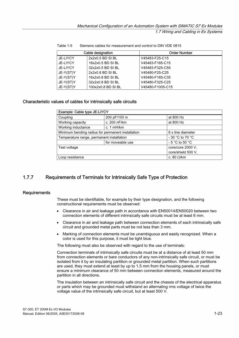
Table 1-5 Siemens cables for measurement and control to DIN VDE 0815
Cable designation Order Number JE-LIYCY JE-LIYCY JE-LIYCY JE-Y(ST)Y JE-Y(ST)Y JE-Y(ST)Y JE-Y(ST)Y
2x2x0.5 BD SI BL 16x2x0.5 BD SI BL 32x2x0.5 BD SI BL 2x2x0.8 BD SI BL 16x2x0.8 BD SI BL 32x2x0.8 BD SI BL 100x2x0.8 BD SI BL
V45483-F25-C15 V45483-F165-C15 V45483-F325-C55 V45480-F25-C25 V45480-F165-C35 V45480-F325-C25 V45480-F1005-C15
Characteristic values of cables for intrinsically safe circuits
Example: Cable type JE-LiYCY Coupling 200 pF/100 m at 800 Hz Working capacity c. 200 nF/km at 800 Hz Working inductance c. 1 mH/km Minimum bending radius for permanent installation 6 x line diameter Temperature range, permanent installation - 30 °C to 70 °C for moveable use - 5 °C to 50 °C Test voltage core/core 2000 V,
core/shield 500 V, Loop resistance c. 80 Ω/km
1.7.7 Requirements of Terminals for Intrinsically Safe Type of Protection
Requirements These must be identifiable, for example by their type designation, and the following constructional requirements must be observed:
• Clearance in air and leakage path in accordance with EN50014/EN50020 between two connection elements of different intrinsically safe circuits must be at least 6 mm.
• Clearance in air and leakage path between connection elements of each intrinsically safe circuit and grounded metal parts must be not less than 3 mm.
• Marking of connection elements must be unambiguous and easily recognized. When a color is used for this purpose, it must be light blue.
The following must also be observed with regard to the use of terminals:
Connection terminals of intrinsically safe circuits must be at a distance of at least 50 mm from connection elements or bare conductors of any non-intrinsically safe circuit, or must be isolated from it by an insulating partition or grounded metal partition. When such partitions are used, they must extend at least by up to 1.5 mm from the housing panels, or must ensure a minimum clearance of 50 mm between connection elements, measured around the partition in all directions.
The insulation between an intrinsically safe circuit and the chassis of the electrical apparatus or parts which may be grounded must withstand an alternating rms voltage of twice the voltage value of the intrinsically safe circuit, but at least 500 V.

Mechanical Configuration of an Automation System with SIMATIC S7 Ex Modules 1.8 Shielding and Measures to Counteract Interference Voltage
S7-300, ET 200M Ex I/O Modules 1-24 Manual, Edition 06/2005, A5E00172008-08
1.8 1.8 Shielding and Measures to Counteract Interference Voltage
1.8.1 Shielding
Definition Shielding is a method of attenuating magnetic, electric or electromagnetic interference fields. Shielding can be subdivided into
• Equipment Shielding
• Line Shielding
1.8.2 Equipment Shielding
General information Particularly observe the following when cabinets and housings are incorporated in control system shielding:
• Cabinet covers such as side panels, rear panels, top and bottom panels, must make contact in an overlapping arrangement at adequate distances (e.g. 50 mm).
• Doors must be given additional contact with the cabinet ground. Use several grounding strips.
• Lines exiting the shielded housing should either be shielded or routed via filters.
• Where the cabinet contains sources of severe interference (transformers, lines to motors, etc.), they must be partitioned from sensitive electronic areas with metal plates. The metal plates must have several low-impedance bolted joints to the cabinet ground.
Interference voltages picked up in the programmable controller via non-Ex signal and supply lines are diverted to the central ground point (standard sectional rail).
The central ground point should have a low-impedance connection to the PE conductor via a copper conductor (> = 10 mm2) which is as short as possible.

Mechanical Configuration of an Automation System with SIMATIC S7 Ex Modules 1.8 Shielding and Measures to Counteract Interference Voltage
S7-300, ET 200M Ex I/O Modules Manual, Edition 06/2005, A5E00172008-08 1-25
1.8.3 Line Shielding
Non-Ex circuits As a rule, shielded lines must always be given a good electrical connection to cabinet potential at each end. Satisfactory suppression of all frequencies picked up can only be achieved by shielding at both ends.
Ex circuits Three aspects must be considered with regard to the design of shielding and grounding of an S7-300 system:
• Ensuring electromagnetic compatibility (EMC)
• Explosion protection
• Personal protection
Shielding of systems with optimum equipotential bonding With regard to the electromagnetic compatibility of the systems, it is important that the system components and, in particular, the lines which connect the components are shielded and that these shields form a complete electrical enclosure wherever possible without gaps. The significance of this requirement increases with the scope of signal frequencies processed in the systems. In ideal cases, the cable shields are connected to the housings which are often metal (or corresponding shielding) of the connected field devices. Since, as a rule, they are linked to chassis ground (or to the PE conductor), the shield of the signal cable is grounded at several points. This optimum procedure with regard to electromagnetic compatibility and personal protection can be applied in these systems without any restrictions.
S7-300
S7-300
Terminal board
Branch cableMain cable
Ex modules
Central ground point
Equipotential bonding conductor
Branch cable Field device
Field device
Figure 1-11 Shielding and equipotential bonding conductors

Mechanical Configuration of an Automation System with SIMATIC S7 Ex Modules 1.8 Shielding and Measures to Counteract Interference Voltage
S7-300, ET 200M Ex I/O Modules 1-26 Manual, Edition 06/2005, A5E00172008-08
Shielding intrinsically safe signal lines EN 60079-14 specifies that there must be general equipotential bonding in hazardous areas to prevent differences in potential and any consequent sparking. Equipotential bonding must be dimensioned and executed in accordance with VDE 0100!
Grounding intrinsically safe circuits In accordance with EN 60079-14, intrinsically safe circuits are generally not grounded. They must be grounded if this is required for safety reasons. They can be grounded if this is required for functional reasons. Grounding can only be carried out at one point by connecting it to the equipotential bonding conductor.
Intrinsically safe signal lines and cables are shielded for measurement reasons and in order to avoid inductive coupling as, in most cases, no signal level is applied.
The following procedure must be implemented when planning the equipotential bonding with intrinsically safe signal lines:
• Metallic housings, the mounting arrangement of which provide reliable contact to structural components, do not require a separate ground as they are incorporated in the equipotential bonding arrangement of the system.
• The shielding is grounded at only one point in order to avoid looping. This is implemented for systems of Zone 1, 2 and 11 outside the hazardous area, preferably in the control room.
The shield must be insulated at the device in the hazardous zone. The measured value is routed via a twisted pair signal line (single cable) to a distribution board and via a multiple cable to the control room. The shield is insulated at all intermediate points.
In zone 0, the shield is connected directly at the apparatus adapter box (mostly zone 1) to the general equipotential bonding system. The apparatus is grounded directly via the ground conductor.

Mechanical Configuration of an Automation System with SIMATIC S7 Ex Modules 1.8 Shielding and Measures to Counteract Interference Voltage
S7-300, ET 200M Ex I/O Modules Manual, Edition 06/2005, A5E00172008-08 1-27
Shielding of lines
Table 1-6 Shielding of Ex lines
Hazardous area Non-Ex area SIMATIC Ex modules
12
3
(1) Sensor or actuator (2) shield (3) line
1 2
(1) Shield support with strain relief (2) cable shield
12
(1) strain relief (2) insulation

Mechanical Configuration of an Automation System with SIMATIC S7 Ex Modules 1.8 Shielding and Measures to Counteract Interference Voltage
S7-300, ET 200M Ex I/O Modules 1-28 Manual, Edition 06/2005, A5E00172008-08
1.8.4 Measures to Counteract Interference Voltages
Assembling the control system Measures to suppress interference voltages are often only implemented when the control system is already in operation and proper reception of a useful signal is impaired. The overheads for such measures, such as special contactors, can often be considerably reduced by observing the following points during the configuration of your control system:
Included here:
• favorable arrangement of equipment and lines
• grounding of all inactive metal elements
• filtering of power cables and signal lines
• shielding of equipment and lines
• special interference-suppression measures
Physical arrangement of equipment and lines Magnetic DC or AC fields of low frequency, such as 50 Hz, can only be sufficiently attenuated at great expense. In such a case, however, you can often solve the problem by providing the greatest possible distance between the interference source and sink.
Note The analog Ex modules operate based on a method which suppresses faults caused by AC system ripple.
Grounding of inactive metal elements Well implemented grounding is an important factor for interference-free assembly. Grounding is understood to mean a good electrical connection of all inactive metal elements (VDE 0160). The principle of surface grounding should be followed. All conductive, inactive metal elements should be grounded!
Observe the following when grounding:
• All ground connections must have a low impedance.
• All metal elements should have a large-area connection. Use particularly wide grounding strips for the connection. The surface of the ground connection and not only its cross section is decisive.
• Screw-type connections should always have spring washers or lock washers.
Mechanical Configuration of an Automation System with SIMATIC S7 Ex Modules 1.8 Shielding and Measures to Counteract Interference Voltage
S7-300, ET 200M Ex I/O Modules Manual, Edition 06/2005, A5E00172008-08 1-29
Protection against electrostatic discharge To protect equipment and modules from electrostatic discharge, metal housings or cabinets enclosed on all sides should be used; these should be given good electrical connection to the grounding point on site, and also connected to the main equipotential bonding conductor.
If you install your controller in a terminal box, use a cast metal or sheet metal housing if possible. Plastic housings should always have a metallized surface.
Doors or covers of housings should be connected to the grounded body of the housing with ground strips or contact springs.
If you are working on the system with the cabinet open, observe the guidelines for protective measures for electrostatically sensitive devices (ESDs).
Electrical systems must be installed so as to avoid the risk of ignition by electrostatic charges. Refer to "Guidelines for avoiding the risk of ignition resulting from electrostatic charges" laid down by the main association of Industrial Employers' Liability Insurance.
If electrostatic charges cannot be avoided, the charge should be kept as low as possible or safe discharge should be provided. The following measures, in particular, should be applied:
• Electrostatic grounding of all conductive elements. Solid materials can be considered as being electrostatically grounded if their leakage resistance at any point is not greater than 106 Ω. Under favorable conditions, 108 Ω is also satisfactory, particularly for small equipment of low capacitance.
• Reducing the electrical resistance of the material moved or parts moved with respect to each other.
• Incorporating grounded metal elements in material subject to electrostatic charging.
• Increasing the relative air humidity. By increasing the relative air humidity to about 65 % with air conditioning, sprays or by hanging moist cloths, the surface resistance of most non-conductive materials can be adequately reduced. However, if the surface of plastic material is water-repellent, this measure will not succeed.
• Ionization of the air.

Mechanical Configuration of an Automation System with SIMATIC S7 Ex Modules 1.8 Shielding and Measures to Counteract Interference Voltage
S7-300, ET 200M Ex I/O Modules 1-30 Manual, Edition 06/2005, A5E00172008-08
1.8.5 The Most Important Basic Rules for Ensuring EMC
Overview To ensure EMC, it is often sufficient to observe some elementary rules. When assembling the control system, take into consideration the five following basic rules.
1. When installing the programmable controllers, ensure high quality surface grounding of the inactive metal elements
– Connect all inactive metal elements over a large area and at low impedance.
– On painted and anodized metal elements, make screwed connections with special contact washers or remove the insulating protective layers.
– Provide a central connection between chassis ground and the ground/protective conductor system.
2. When wiring always follow the code of practice for line routing
– Subdivide the cabling into line groups.
– (AC power cables, supply lines, Ex and non-Ex signal lines, data lines).
– Always install power cables and signal or data lines in separate ducts or bundles.
– Route the signal and data lines as closely as possible to grounded surfaces such as supporting bars, metal rails, cabinet sheet metal panels.
– Install Ex and non-Ex signal lines in separate ducts.
3. Ensure that line shields are properly secured
– Data lines should be shielded when laid. The shield should be connected at both ends.
– Analog lines should be shielded when laid. When low-amplitude signals are transmitted, it may be advantageous if the shield is connected at only one end.
– For Ex signal lines, connect the line shields only at the sensor or actuator end. Ensure the connected shield continues without interruption as far as the module, but do not connect it there.
– Ensure the shield has a low-impedance connection to the equipotential bonding conductor.
– Use metal or metallized plug housings for shielded data lines.
4. Implement special EMC measures for particular applications
– For all inductances, fit quenching elements provided they are not already contained in the output modules.
– Use incandescent bulbs for lighting the cabinets and avoid fluorescent lamps.
5. Provide a standard reference potential and ground all electrical apparatus if possible
– Take care to ensure specific grounding measures. Grounding of the control system is a protective and functional measure.
– System elements and cabinets should be connected in star-configuration to the ground/protective conductor system. In this way you can avoid the formation of ground loops.
– In the event of potential differences between system elements and cabinets, install adequately rated equipotential bonding conductors.
Mechanical Configuration of an Automation System with SIMATIC S7 Ex Modules 1.9 Lightning Protection
S7-300, ET 200M Ex I/O Modules Manual, Edition 06/2005, A5E00172008-08 1-31
1.9 1.9 Lightning Protection
1.9.1 Measures
Overview In systems with hazardous areas, the most important task, not least for reasons of explosion protection, is to avoid overvoltages; where this is not possible, they must be reduced and safely discharged.
In addition to the provision of external lightning protection, these measures cover internal lightning protection and overvoltage protection. These measures must be coordinated with the equipment-related EMC.
You will find more detailed information on the subjects of lightning protection and overvoltage protection in the manuals of the individual systems as specified in the foreword. Here, you will also find an overview of the components which can be used for this purpose.
1.9.2 External Lightning Protection/Shielding of Buildings
Measures External lightning protection is a measure for preventing damage to buildings and fire damage. For this task, a large-mesh wire cage consisting of lightning conductors and down conductors is sufficient.
On buildings with sensitive electronic equipment such as control rooms, the external lightning protection must be supplemented by a building shield. For these purposes, where possible, metal facades and reinforcements of walls, floors and ceilings on or in the building are connected to form shield cages. Where this is not possible, the lightning conductor and down conductor should have a reduced mesh size and, where applicable, the supporting structure of the intermediate floor should be electrically interconnected.
Electrical equipment protruding above roof level must be protected against direct lightning strikes. When such equipment is metallically connected to the external lightning protection system, a partial current is picked up by the building in the event of a lightning strike; this can result in destruction of the equipment sensitive to overvoltages. The pick-up of partial lightning currents can be prevented by protecting the electrical equipment protruding above the roof from direct lightning strikes by means of rods insulated from the equipment (45 degree protective area), or by cage-type tensioned wires or cables.
The down conductors for external lightning protection and, if applicable, the reinforcements and supporting structures, should be connected to the ground system. Each individual building has its own functioning ground system. The ground systems are meshed to create a common grounding network. The voltage between the buildings is thus reduced.
Mechanical Configuration of an Automation System with SIMATIC S7 Ex Modules 1.9 Lightning Protection
S7-300, ET 200M Ex I/O Modules 1-32 Manual, Edition 06/2005, A5E00172008-08
1.9.3 Creating distributed systems with S7-300 and ET 200M
Measures The process engineering of a plant, such as gas supply, requires a wide-ranging exchange of information between the systems with the distributed Ex I/O devices and the central, electrical or electronic measurement and control system. This necessitates a great number of cable connections, sometimes extending over several hundred meters - in the case of gas storage systems, over several thousands of meters. In the event of a lightning strike, therefore, extensive voltage pick-up occurs.
A distributed arrangement of instrumentation and control equipment with relatively short cables to the plant, and the connection of distributed I/O stations to each other and to the central controller via a bus (PROFIBUS-DP) or fiber-optic cable, are an important measure for reducing overvoltages between sections of the plant.
You will find more detailed information on this arrangement in the manuals specified in the foreword.
1.9.4 Shielding of Cables and Buildings
Measures Overvoltages between separate plant sections or buildings cannot be avoided in practice by meshing. In the event of a lightning strike, a circulating current will flow over the path created by metal connections between the buildings or between a building and I/O device. Cable cores are ideal for this purpose. The lightning or partial lightning current must therefore be offered other conductive connections. Shielding which can be implemented in different ways is particularly suitable, for example:
• a helical current-rated metal strip or metal braid as the cable shield, e.g. NYCY or A2Y(K)Y.
• By installing the cables in continuously connected metal conduits which are grounded at both ends.
• By installing the cables in reinforced concrete ducts with through-connected reinforcement or on closed metal cable racks.
• By laying conductors (shield conductors) in parallel with cables. This measure, however, only relieves the cables of partial lightning currents.
or
• By laying fiber-optic cables.
Overvoltage-sensitive equipment must also be shielded to ensure the currents at the cable ends cannot destroy this equipment. This is achieved with metal housings or by installing the equipment in metal cabinets which are connected to the ground conductor.

Mechanical Configuration of an Automation System with SIMATIC S7 Ex Modules 1.9 Lightning Protection
S7-300, ET 200M Ex I/O Modules Manual, Edition 06/2005, A5E00172008-08 1-33
1.9.5 Equipotential Bonding for Lightning Protection
Measures "Internal lightning protection" covers all the additional measures which prevent the magnetic and electrical effects of the lightning current within the building to be protected. These particularly include the "equipotential bonding for lightning protection" which reduces the potential differences caused by the lightning current.
The principle of internal lightning protection is to incorporate in the equipotential bonding for lightning protection all the lines entering and exiting from a volume to be protected; these include, apart from all metal piping such as that for water, gas and heat, all power and information cables the cores of which are connected via suitable protective devices. Since considerable, partial lightning currents can flow over such lines and must be discharged by the protective devices, they must be chosen for a suitable current carrying capacity (lightning current conductors).
1.9.6 Overvoltage Protection
General Effectiveness depends very much on the connection and cable routing of the overvoltage protection devices. When the devices are used in hazardous areas or intrinsically safe circuits, EN60079-14 must be adhered to.
When the system is installed, the minimum igniting curves and maximum heating specified by EN 50020 must be adhered to.
Overvoltage protection in intrinsically safe circuits Overvoltage protection devices can protect intrinsically safe circuits from overvoltage.
Hazardous area
Lightning arrester 1
SensorEx module
central grounding point
Safe area
Lightning arrester 2
Figure 1-12 Overvoltage protection in intrinsically safe circuits

Mechanical Configuration of an Automation System with SIMATIC S7 Ex Modules 1.9 Lightning Protection
S7-300, ET 200M Ex I/O Modules 1-34 Manual, Edition 06/2005, A5E00172008-08
The discussion of safety-relevant aspects is limited to the direct comparison of the data for inductance and capacity.
Table 1-7 Comparison of data for inductance and capacity
Ex module Comparison Lightning arrester 1 Line Lightning arrester 2
Sensor/actuator
La ≥ LBD1 +LLtg +LBD2 +Li Ca ≥ CBD1 +CLtg +CBD2 +Ci
Table 1-8 Example of the comparison of data for inductance and capacity
Ex module Comparison Lightning arrester 1 Line Lightning arrester 2
Sensor/actuator
La = 4 mH ≥ < 0.5 µH < 50 µH < 0.5 mH < 0.6 mH Ca = 270 nF ≥ < 1 nF < 10 nF < 6 nF < 6 nF
The overvoltage protection elements described in this section are only effective if used together with external lightning protection. External lightning protection measures reduce the effects of a lightning strike.
You can obtain suitable lightning conductors for Ex modules from:
DEHN + SÖHNE GmbH + Co. KG Elektrotechnische Fabrik Hans-Dehn-Str. 1 D-92318 Neumarkt http://www.dehn.de

Mechanical Configuration of an Automation System with SIMATIC S7 Ex Modules 1.9 Lightning Protection
S7-300, ET 200M Ex I/O Modules Manual, Edition 06/2005, A5E00172008-08 1-35
1.9.7 Example of Lightning and Overvoltage Protection
Lightning/overvoltage protection for a gas compressor station Fig. "Lightning/overvoltage protection for a gas compressor station" shows an example of how protective devices can be used.
1 2 3 4
ME
B
M
123
45o
EB
Pro
tect
ive
de
vice
fo
r A
C p
ow
er
syst
em
Ca
ble
du
ct (
shie
lde
d)
An
ne
x
M&
C
eq
uip
me
nt
M&
C
cab
ine
tLV
sy
ste
mC
on
tro
l co
nso
le
Insu
latin
g f
lan
ge
Lig
ht
fixtu
re
Me
tal
con
du
it
Co
mp
ress
or
ba
y (s
hie
lde
d)
Ca
ble
ra
cks
as
EB
rin
g
Insu
latio
n
Sm
oke
de
tect
or
Sta
tion
gro
un
d
Su
b-d
istr
ibu
tion
Co
ntr
ol r
oo
m
(sh
ield
ed
)
Pro
tect
ive
de
vice
fo
r M
&C
sys
tem
s
Sp
ark
ga
p
Pro
tect
ive
de
vice
, re
qu
ire
d f
or
hig
h-c
ost
M&
C e
qu
ipm
en
t
Pro
tect
ive
de
vice
, n
ot
req
uire
d f
or
shie
lde
d c
ab
les
an
d lo
w-c
ost
M
&C
eq
uip
me
nt
Pro
tect
ive
de
vice
, n
ot
req
uire
d f
or
eq
uip
me
nt
with
hig
h d
iele
ctric
stre
ng
th
Pro
tect
ive
de
vice
, n
ot
req
uire
d w
ith s
uita
ble
sys
tem
sh
ield
ing
Figure 1-13 Lightning/overvoltage protection for a gas compressor station

Mechanical Configuration of an Automation System with SIMATIC S7 Ex Modules 1.9 Lightning Protection
S7-300, ET 200M Ex I/O Modules 1-36 Manual, Edition 06/2005, A5E00172008-08
1.9.8 Lightning Strike
Measures When lightning strikes an explosive atmosphere it always ignites. There is also a risk of ignition due to an excessive rise in temperature in the lightning discharge paths. In order to prevent, at Zones 0, 1 and 10 themselves, the harmful effects of lightning strikes occurring outside of these zones, surge diverters, for example, must be fitted at suitable points. Tank insulation covered with earth and made of metal materials with electrical equipment or electrically conductive system sections, which are electrically insulated with respect to the tank, require equipotential bonding; for example, in the case of measurement and control systems and filling pipes.
Note Lightning protection equipment and grounding systems must be tested by an expert upon their completion and at regular intervals. Based on ElexV, the testing interval for electrical systems and lightning protection systems for hazardous areas is three years.
Summary:
• Enhanced external lightning protection (reduced mesh size, increased number of down conductors) on all buildings and systems.
• Meshing of grounding systems in the building to create area grounding.
• Meshing of equipotential bonding.
• Fitting of lightning conductors and surge diverters in the power system.
• Fitting of overvoltage fine-protection devices at both ends of measurement and control cables.
• Shielding of M&C cables.
• M&C cables with twisted pairs of cores.
Mechanical Configuration of an Automation System with SIMATIC S7 Ex Modules 1.10 Installation Work in Hazardous Areas
S7-300, ET 200M Ex I/O Modules Manual, Edition 06/2005, A5E00172008-08 1-37
1.10 1.10 Installation Work in Hazardous Areas
1.10.1 Safety Measures
Introduction All possible measures which eliminate the risk of explosion must be implemented not only when using programmable controllers in hazardous areas but also during the installation stage.
Sparks capable of causing ignition during mechanical work Tools which tend to produce sparks must not be used for working in potentially explosive systems or system sections in operation. Copperberyllium is a suitable material for tools such as screwdrivers, pliers, wrenches, hammers and chisels. Since this material has low wear-resistance, the tools should be used with care.
Sparks capable of causing ignition during mechanical work
low when bare steel elements strike each other possible when steel elements collide or drop great when striking rusty steel very great when striking rusty steel with an alloy coating (e.g. aluminum paint)
The possibility of creating sparks capable of causing ignition is substantially reduced by using non-sparking tools. Exception: when the tool is harder than the workpiece.
Measures for eliminating the risk of explosion Safely closing off the working area, e.g. with dummy panels.
• Good ventilation of the rooms.
• Flushing with inert gas. Testing the effectiveness of the flushing (gas tester). Then working with a normal tool.
If the risk of explosion at the workplace cannot be eliminated, the following measures must be implemented:
• Avoidance of collisions and dropping of steel elements.
• Wearing antistatic shoes, e.g. leather shoes or using shoe grounding strips.
• Avoiding rust layers and aluminum coating at impact points. If this is not possible, eliminating the risk of explosion locally, e.g. with inert gas.
• Adequate air supply and waste air disposal.
• Removing or enclosing readily flammable substances in the vicinity.
• Keeping the workplace and, if applicable, floor moist.

Mechanical Configuration of an Automation System with SIMATIC S7 Ex Modules 1.10 Installation Work in Hazardous Areas
S7-300, ET 200M Ex I/O Modules 1-38 Manual, Edition 06/2005, A5E00172008-08
Table 1-9 Safety Measures
Working area Safety Measures Installations with readily flammable gas and vapor-air mixtures, e.g. hydrogen, city gas, acetylene and hydrogen sulphide
Working only allowed after implementation of special safety measures and with written permission of plant manager. Only non-sparking tools to be used (tool softer than workpiece).
Installations with gas and vapor-air mixtures such as methane, propane, butane and petrol
Sufficient to use non-sparking tools. Exception: For materials with rust formation and aluminum coating or similar, special protective measures required.
Installations with risk of explosion from readily flammable dust
Remove dust deposits. Keep working area wet and protect against dust formation. Normal tools may be used.
Note Working on energized electrical installations and apparatus in hazardous industrial premises is prohibited. This also includes the disconnection of live control lines for test purposes.
As an exception, work on intrinsically safe circuits is permitted; also, in special cases, work on other electrical systems where the user has certified in writing that there is no risk of explosion for the duration of the work at the site.
If necessary, a fire permit must also be obtained.
Grounding and short-circuiting may only be carried out in hazardous industrial premises when there is no risk of explosion at the point of grounding and short-circuiting.
Use measuring instruments which are approved for the zones to test for no voltages.
1.10.2 Use of Ex Assemblies in Hazardous Zone 2
License SIMATIC S7 Ex modules are permitted for use in zone 2 (category 3G). Note in this case the specific conditions on the EU special test certificate (see Appendix "Certificates of Conformity").
See also Overview of diagnostic functions (Page A-1)
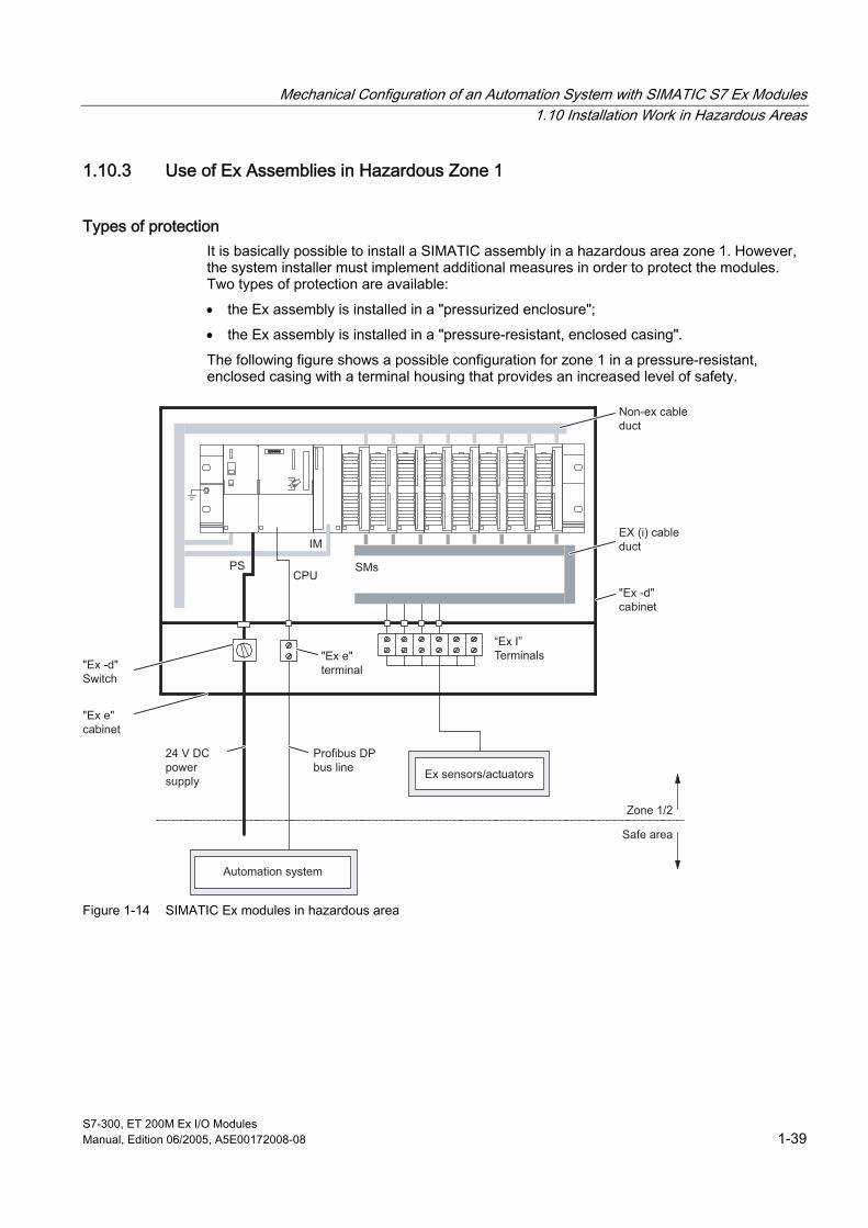
Mechanical Configuration of an Automation System with SIMATIC S7 Ex Modules 1.10 Installation Work in Hazardous Areas
S7-300, ET 200M Ex I/O Modules Manual, Edition 06/2005, A5E00172008-08 1-39
1.10.3 Use of Ex Assemblies in Hazardous Zone 1
Types of protection It is basically possible to install a SIMATIC assembly in a hazardous area zone 1. However, the system installer must implement additional measures in order to protect the modules. Two types of protection are available:
• the Ex assembly is installed in a "pressurized enclosure";
• the Ex assembly is installed in a "pressure-resistant, enclosed casing".
The following figure shows a possible configuration for zone 1 in a pressure-resistant, enclosed casing with a terminal housing that provides an increased level of safety.
PSCPU
SMs
IM
Non-ex cable duct
"Ex -d"Switch
"Ex e"cabinet
"Ex e"terminal
“Ex I”Terminals
Profibus DP bus line
Automation system
Ex sensors/actuators
Safe area
Zone 1/2
24 V DC power supply
EX (i) cable duct
"Ex -d"cabinet
Figure 1-14 SIMATIC Ex modules in hazardous area

Mechanical Configuration of an Automation System with SIMATIC S7 Ex Modules 1.10 Installation Work in Hazardous Areas
S7-300, ET 200M Ex I/O Modules 1-40 Manual, Edition 06/2005, A5E00172008-08
Housing The selected type of housing is characterized by the fact that it is able to withstand explosions occurring inside the housing and that an explosive gas/air mixture surrounding the housing is not ignited. In addition, the surface temperature does not exceed the limit values of the temperature classes. Cable glands that are protected against transmission of internal ignition and isolated against the housing wall must be used for routing the supply leads into the pressure-resistant, enclosed casing.
A housing with "increased safety" is used as a terminal compartment. Special screwed glands are used for the cable entries.
The housing must be certified by a testing authority to comply with the "EEx d" type of protection and the relevant design requirements.
Explosion protection of the housing: EEx de II T5 .. T6.
Cables The cables used must comply with the EN 50 014 and EN 50 020 standards for intrinsically safe circuits or EN 50 039 for circuits with increased safety.
The cables for the assembly are to be installed in such a way that they are endangered neither by thermal, mechanical nor chemical load or stress.
Note If necessary, the cables should be installed in cable conduits.
Terminals The terminal connectors for the power supply cable and the bus line should always meet the requirements of the "increased safety" tape of protection. The clamping points of the intrinsically safe circuits should always be implemented according to the guidelines of "Intrinsic safety".
Protective device The assembly is connected to a 24 V DC supply circuit fed by a power supply unit with safe electrical isolation. The supply circuit must be protected by an appropriate circuit-breaker. This circuit-breaker is installed outside the Ex zone.
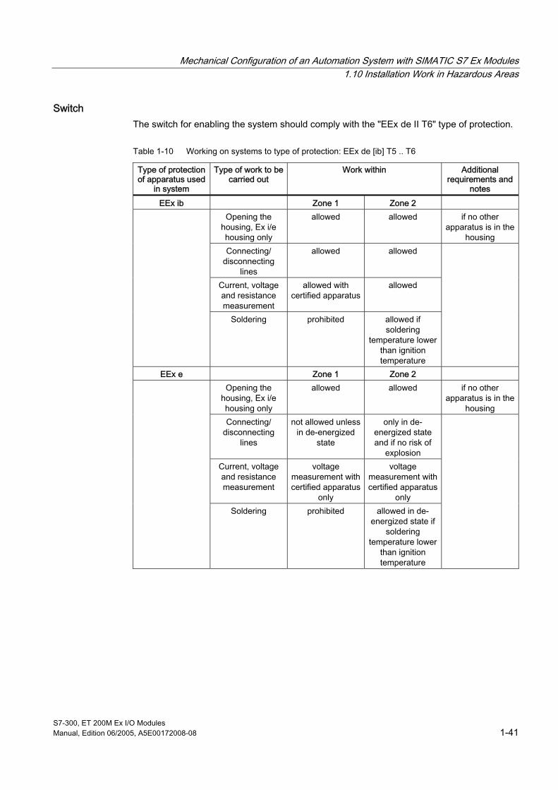
Mechanical Configuration of an Automation System with SIMATIC S7 Ex Modules 1.10 Installation Work in Hazardous Areas
S7-300, ET 200M Ex I/O Modules Manual, Edition 06/2005, A5E00172008-08 1-41
Switch The switch for enabling the system should comply with the "EEx de II T6" type of protection.
Table 1-10 Working on systems to type of protection: EEx de [ib] T5 .. T6
Type of protection of apparatus used
in system
Type of work to be carried out
Work within Additional requirements and
notes
EEx ib Zone 1 Zone 2 Opening the
housing, Ex i/e housing only
allowed allowed if no other apparatus is in the
housing Connecting/
disconnecting lines
allowed allowed
Current, voltage and resistance measurement
allowed with certified apparatus
allowed
Soldering prohibited allowed if soldering
temperature lower than ignition temperature
EEx e Zone 1 Zone 2 Opening the
housing, Ex i/e housing only
allowed allowed if no other apparatus is in the
housing Connecting/
disconnecting lines
not allowed unless in de-energized
state
only in de-energized state and if no risk of
explosion Current, voltage and resistance measurement
voltage measurement with certified apparatus
only
voltage measurement with certified apparatus
only
Soldering prohibited allowed in de-energized state if
soldering temperature lower
than ignition temperature

Mechanical Configuration of an Automation System with SIMATIC S7 Ex Modules 1.11 Maintenance of Electrical Apparatus
S7-300, ET 200M Ex I/O Modules 1-42 Manual, Edition 06/2005, A5E00172008-08
Type of protection of apparatus used
in system
Type of work to be carried out
Work within Additional requirements and
notes EEx d Zone 1 Zone 2
Opening the housing, Ex d housing only
prohibited allowed if no risk of explosion
apparatus in pressure-resistant enclosure are no longer protected against explosion
if housing is opened
Connecting/ disconnecting
lines
not allowed unless in de-energized
state
allowed if no risk of explosion
Current, voltage and resistance measurement
Work not possible allowed if no risk of explosion
Soldering prohibited allowed in de-energized state if
soldering temperature lower
than ignition temperature
1.11 1.11 Maintenance of Electrical Apparatus
Replacing equipment Work on electrical systems or equipment can only be carried out if a "permit" has been granted. If electrical equipment is replaced, attention must be paid to the correct temperature class, explosion group, and corresponding (Ex) zone. Certificates of conformity, EU special test certificates, and design approval must be available.
Maintaining apparatus Repaired electrical apparatus may only be placed in operation again after testing by a recognized expert in accordance with paragraph 15 of ElexV, and the test has been certified, unless explosion protection has not been affected by the repair. If the repair affects explosion protection, only original spare parts may be used. Improvised repairs which no longer ensure explosion protection of apparatus are not permitted.

S7-300, ET 200M Ex I/O Modules Manual, Edition 06/2005, A5E00172008-08 2-1
SIMATIC S7 Ex Digital Modules 22.1 2.1 Chapter overview
Overview The following SIMATIC S7 Ex digital modules are described in this chapter:
• Digital input SM 321; DI 4 x NAMUR
Order number: 6ES7321-7RD00-0AB0
• Digital output SM 322; DO 4 x 24V/10 mA
Order number: 6ES7322-5SD00-0AB0
• Digital output SM 322; DO 4 x 15V/20 mA
Order number: 6ES7322-5RD00-0AB0
Notes You will find information on the relevant safety standards and on other safety regulations in Appendix "Standards and Licenses" .
The general technical specifications for S7-300 modules apply.

SIMATIC S7 Ex Digital Modules 2.2 Digital input module SM 321; DI 4 x NAMUR (6ES7321-7RD00-0AB0)
S7-300, ET 200M Ex I/O Modules 2-2 Manual, Edition 06/2005, A5E00172008-08
2.2 2.2 Digital input module SM 321; DI 4 x NAMUR (6ES7321-7RD00-0AB0)
2.2.1 Features and technical specifications
Order Number 6ES7321-7RD00-0AB0
Features The SM 321; DI 4 x NAMUR has the following features:
• 4 inputs
– isolated with respect to bus
– isolated among each other
• load voltage 24 V DC
• connectable sensors
– in compliance with DIN 19234 or NAMUR (with diagnostic evaluation)
– interconnected mechanical contacts (with diagnostic evaluation)
– open-circuited mechanical contacts (without diagnostics)
• 4 short-circuit-proof outputs for sensor power supply (8.2V)
• Operating points:
logic "1" ≥ 2.1 mA
logic "0" ≤ 1.2 mA
• Status indication (0...3) = green LEDs
Fault indications = red LEDs for
– group fault indication (SF)
– channel-referred fault indication for short-circuit and wire break (F0 ... F3)
• configurable diagnostics
• configurable diagnostic interrupt
• configurable hardware interrupt
• Intrinsic safety of inputs in accordance with EN 50020
• 2-wire sensor connection

SIMATIC S7 Ex Digital Modules 2.2 Digital input module SM 321; DI 4 x NAMUR (6ES7321-7RD00-0AB0)
S7-300, ET 200M Ex I/O Modules Manual, Edition 06/2005, A5E00172008-08 2-3
Terminal diagram of SM 321; DI 4 x NAMUR
9
5
3
4
1K
1K
1K
1K
Input 1
Input 0
Input 2
Input 3
X 23 4
F0
SF
0
F1
1
F2
2
F33
L +1
2
5
6
7
8
9
10
11
12
1314
15
16
17
1819
20
1K
1K
1K
1K
+8,2 V
M
+8,2 V
+8,2 V
+8,2 V
3
4
L +12
67
8
10
11
12
1314
15
16
17
1819
20 M
+8,2 V
+8,2 V
+8,2 V
10k1k
10k
321-7RD00-0AB0
SM 321DI 4 x NAMUR
Contactwithout monitoring
Contact withmonitoring for- wire break(only if resistor connected directly at contact)
Terminal diagram for NAMUR sensor with monitoring for- wire break- short-circuit
Terminal diagram for contacts (connection variants)
Contact withmonitoring for- wire break- conductor short-circuit(only if resistor connected directly at contact)
Channel number
0...3 status indication [green]
SF Group error indicator [red]F (0...3) channel-specific fault indication [red]
Figure 2-1 Terminal diagram of digital input module SM 321; DI 4 x NAMUR
Notes on intrinsically-safe installation You must connect the DM 370 dummy module between the CPU or IM 153 (in a distributed configuration) and the Ex I/O modules whose signal cables lead into the hazardous location. In a distributed configuration with an active backplane bus, you should use the ex dividing panel/ex barrier instead of the dummy module.
Power supply for an intrinsically-safe structure In order to maintain the clearances and creepage distances, L+/M must be routed via the line chamber LK393 when operating modules with signal cables that lead to the hazardous location.

SIMATIC S7 Ex Digital Modules 2.2 Digital input module SM 321; DI 4 x NAMUR (6ES7321-7RD00-0AB0)
S7-300, ET 200M Ex I/O Modules 2-4 Manual, Edition 06/2005, A5E00172008-08
Block diagram SM 321; DI 4 x NAMUR
L +
M
8.2 V
5 V
1k
1k
10k
8.2 V
1k
10k
8.2 V
1k
8.2 V
1k
Load voltage 24 V
Sensor supply
Channel 0
Contact without monitoring
MonitoringL+ moduleMonitoringinternal supply voltage
Status
Fault
Logic
Logic
S7-300 back-plane bus
Eval-uation stage
Channel fault indication (F0…F3)
red
Statusdisplay (0…3)
green
Group errordisplay (SF)
red
Contact withmonitoring for- wire break(resistor connected directlyat contact)
Contact withmonitoring for- wire break- conductor short-circuit(resistor connected directlyat contact)
NAMUR sensormonitoring for- wire break- conductor short-circuit
Channel 1
Channel 2
Connection variants
Channel 3
Figure 2-2 Block diagram of digital input module SM 321; DI 4 x NAMUR

SIMATIC S7 Ex Digital Modules 2.2 Digital input module SM 321; DI 4 x NAMUR (6ES7321-7RD00-0AB0)
S7-300, ET 200M Ex I/O Modules Manual, Edition 06/2005, A5E00172008-08 2-5
Technical specifications of the SM 321; DI 4 x NAMUR
Dimensions and Weight Dimensions W x H x D (mm) 40 x 125 x 120 Weight approx. 230 g Module-specific data Number of inputs 4 Line length, shielded max. 200 m KEMA protection (see Appendix)
II 3 (2) G EEx nA [ib] IIC T4
Test number KEMA 01ATEX1057 X FM protection (see Appendix)
Class I, Division 2, Group A, B, C, D T4 Class I, Zone 2, Group IIC T4
Voltages, currents, potentials Bus power supply Rated load voltage L+ • Reverse voltage protection
DC 5 V DC 24 V yes
Number of inputs which can be activated simultaneously 4 Galvanic isolation • between the channels and backplane bus yes • between the channels and load voltage L+ yes • between the channels yes • between the backplane bus and load voltage L+ yes Permissible difference in potential (UISO) for signals from a hazardous area • between the channels and backplane bus DC 60 V
AC 30 V • between the channels and load voltage L+ DC 60 V
AC 30 V • between the channels DC 60 V
AC 30 V • between the backplane bus and load voltage L+ DC 60 V
AC 30 V Permissible difference in potential (UISO) with signals from the non-hazardous area • between the channels and backplane bus DC 400 V
AC 250 V • between the channels and load voltage L+ DC 400 V
AC 250 V • between the channels DC 400 V
AC 250 V • between the backplane bus and load voltage L+ DC 75 V
AC 60 V

SIMATIC S7 Ex Digital Modules 2.2 Digital input module SM 321; DI 4 x NAMUR (6ES7321-7RD00-0AB0)
S7-300, ET 200M Ex I/O Modules 2-6 Manual, Edition 06/2005, A5E00172008-08
Insulation tested • Channels to backplane bus and load voltage L+ with AC 1500 V • Channels to each other with AC 1500 V • between the backplane bus and load voltage L+ with DC 500 V Current input • from backplane bus • from load voltage L+
max. 80 mA max. 50 mA
Module power loss typical 1.1 W Status, interrupts, diagnostics Status indication • Inputs green LED per channel Interrupts • Hardware interrupt • Diagnostic interrupt
configurable configurable
Diagnostic functions • Group fault indication red LED (SF) • Channel fault indication red LED (F) per channel • Diagnostic functions readout possible monitoring for • Short-circuit I > 8.5 mA • Wire break I ≤ 0.1 mA Safety specifications (see EU special test certificate KEMA 01ATEX1057 X in Appendix under "Certificates of Conformity") Maximum values of input circuits (per channel) • U0 (no-load output voltage) max. 5.9 V • I0 (short-circuit current) max. 14.1 mA • P0 (load power) max. 33.7 mW • L0 (permissible external inductance) max. 100 mH • C0 (permissible external capacity) max. 3 µF • Um (fault voltage) max. DC 60V
AC 30V • Ta (permissible ambient temperature) max. 60°C Data for sensor selection In accordance with DIN 19234 or NAMUR Input current • at signal "1" 2.1 to 7 mA • at signal "0" 0.35 to 1.2 mA Time/frequency Interrupt conditioning time for • Interrupt conditioning only max. 250 µs • Interrupt and diagnostic conditioning max. 250 µs Input delay (EV) • configurable yes • Nominal value type 0.1/0.5/3/15/20 ms
See also The LK 393 line chamber (Page 1-5)
Configuration of an S7-300 with Ex I/O Modules (Page 1-8)
Configuration of an ET 200M with Ex I/O modules (Page 1-11)

SIMATIC S7 Ex Digital Modules 2.2 Digital input module SM 321; DI 4 x NAMUR (6ES7321-7RD00-0AB0)
S7-300, ET 200M Ex I/O Modules Manual, Edition 06/2005, A5E00172008-08 2-7
2.2.2 Parameterization
Parameterization You set the parameters of the digital input module SM 321, DI 4 x NAMUR with STEP 7. You must implement the settings in CPU STOP mode. The parameters set in this way are stored in the CPU during transfer from PG to S7-300. These parameters are transferred to the digital module during the status change from STOP-->RUN.
You can also change some parameters in the user program with SFC 55 to 57.
The parameters for the 2 parameterization alternatives are subdivided into:
• static parameters
• dynamic parameters
The table below shows the characteristics of static and dynamic parameters.
Table 2-1 Static and dynamic parameters of SM 321; DI 4 x NAMUR
Parameter can be set with CPU operating status static Programming Devices STOP dynamic Programming Devices STOP dynamic SFCs 55 to 57 in user program RUN
Default settings The SM 321, DI 4 x NAMUR features default settings for diagnostics, interrupts etc..
These default settings are applicable when the digital input module has not been parameterized via STEP 7.
Configurable characteristics The characteristics of the SM 321, DI 4 x NAMUR can be parameterized with the following parameter blocks:
• Basic settings
• Diagnostics
• Hardware interrupts

SIMATIC S7 Ex Digital Modules 2.2 Digital input module SM 321; DI 4 x NAMUR (6ES7321-7RD00-0AB0)
S7-300, ET 200M Ex I/O Modules 2-8 Manual, Edition 06/2005, A5E00172008-08
Channel group allocation The table shows the allocation of the 4 channels to the channel groups of the SM 321; DI 4 x NAMUR.
Table 2-2 Allocation of 4 digital input channels to the 4 channel groups of SM 321; DI 4 x NAMUR
Channel Allocated channel group
Channel 0 Channel group 0 Channel 1 Channel group 1 Channel 2 Channel group 2 Channel 3 Channel group 3
Parameters of the digital input module The table below provides an overview of the parameters of the SM 321; DI 4 x NAMUR and shows what parameters
• are static or dynamic and
• can be used for the module as a whole or for a channel group.
Table 2-3 Parameters of SM 321; DI 4 x NAMUR
SM 321; DI 4 x NAMUR Parameter Range of
values Default Type of Effective
range Basic settings • Input delay (ms) • Hardware interrupt enable • Enable diagnostic interrupt
0,1/0,5/3/15/20 yes/no yes/no
3 no no
static dynamic dynamic
module module module
Diagnostics • Wire-break monitoring • Short to M
yes/no yes/no
no no
static static
Channel group Channel group
Hardware interrupts • with leading edge • at trailing edge
yes/no yes/no
no no
dynamic dynamic
Channel group Channel group

SIMATIC S7 Ex Digital Modules 2.2 Digital input module SM 321; DI 4 x NAMUR (6ES7321-7RD00-0AB0)
S7-300, ET 200M Ex I/O Modules Manual, Edition 06/2005, A5E00172008-08 2-9
Input delay The table below shows the possible configurable input delay times for the SM 321; DI 4 x NAMUR and their tolerances.
Table 2-4 Delay times of input signal for SM 321; DI 4 x NAMUR
Input delay Tolerance
0.1 ms 75 to 150 μs 0.5 ms 0.4 to 0.8 ms
3 ms (default) 2.8 to 3.5 ms 15 ms 14.5 to 15.5 ms 20 ms 19 to 21 ms
2.2.3 Diagnostic messages
Introduction You can use the diagnostic function to determine whether signal acquisition takes place without errors.
Parameterizing diagnostics Output mode is parameterized with STEP 7.
Diagnostic evaluation When evaluating the diagnostics, a differentiation must be made between configurable and non-configurable diagnostic messages. In the case of the configurable diagnostic message "wire break" or "short to M", diagnostics is only signaled when diagnostic evaluation has been enabled by means of parameterization (parameter "wire break" or "short to M").
Non-configurable diagnostic messages are general, i.e. independent of parameterization.
A diagnostic signal results in a diagnostic interrupt being triggered providing the diagnostic interrupt has been enabled by way of parameterization.
Irrespective of the parameterization, known module errors always result in the SF LED and the corresponding channel fault LED lighting irrespective of the CPU operating status (at POWER ON).
Exception:
The SF LED and the corresponding channel fault LED light in the event of a wire break only when parameterization is enabled.

SIMATIC S7 Ex Digital Modules 2.2 Digital input module SM 321; DI 4 x NAMUR (6ES7321-7RD00-0AB0)
S7-300, ET 200M Ex I/O Modules 2-10 Manual, Edition 06/2005, A5E00172008-08
Diagnostics of the digital input module The table below provides an overview of the parameters of the SM 321; DI 4 x NAMUR. You enable diagnostics in STEP 7.
The diagnostics information refers to either the channel groups or the entire module.
Table 2-5 Diagnostic messages of SM 321; DI 4 x NAMUR
Diagnostic message Effective range of diagnostics Configurable Wire break
Short to M
Channel group yes
Incorrect parameters in module Module not parameterized External auxiliary voltage missing No internal auxiliary voltage Fuse blown Time watchdog tripped EPROM error RAM error CPU error Hardware interrupt lost
Module
no
Reading out diagnostic messages You can read out system diagnostics with STEP 7. You can read detailed diagnostic messages from the module in the user program with SFC 59.

SIMATIC S7 Ex Digital Modules 2.2 Digital input module SM 321; DI 4 x NAMUR (6ES7321-7RD00-0AB0)
S7-300, ET 200M Ex I/O Modules Manual, Edition 06/2005, A5E00172008-08 2-11
Faults and corrective measures The table below provides a list of possible causes and corresponding corrective measures for individual diagnostic messages.
Bear in mind that, in order to detect faults which are indicated by means of configurable diagnostic messages, the module must also be parameterized accordingly.
Table 2-6 Diagnostic messages as well as their causes and corrective measures in SM 321; DI 4 x NAMUR
Diagnostic message
Possible fault causes Corrective measures
Short-circuit between the two sensor lines
Eliminate short-circuit Short to M (I > 8.5 mA)
with contacts as sensor 1 kΩ series resistor not fitted in line to contact
Connect 1 kΩ resistor directly at contact in line
Conductor break between module and NAMUR sensor
Connect line
with contact as sensor (wire break monitoring enabled)
10 kΩ resistor not fitted or interrupted directly at contact
with contact as sensor (without monitoring)
Wire break (I ≤ 0.1 m A)
Channel not used (open)
disable channel by parameterization "diagnostics wire break"
Incorrect parameters in module
Invalid parameters loaded in module by means of SFC
Check parameterization of module and re-load valid parameters
Module not parameterized
Module not supplied with parameters Include module in parameterization
External auxiliary voltage missing
No module supply voltage L+ Provide L+ supply
No module supply voltage L+ Provide L+ supply No internal auxiliary voltage module-internal fuse defective Replace module Fuse blown module-internal fuse defective Replace module
partially high electromagnetic interference
Eliminate interference sources Time watchdog tripped
Module defective Replace module partially high electromagnetic interference
Eliminate interference sources and switch CPU supply voltage OFF/ON
EPROM error RAM error CPU error Module defective Replace module
Hardware interrupt lost
Succession of hardware interrupt is faster than the CPU can process
Change interrupt processing in CPU and reparameterize module if necessary

SIMATIC S7 Ex Digital Modules 2.2 Digital input module SM 321; DI 4 x NAMUR (6ES7321-7RD00-0AB0)
S7-300, ET 200M Ex I/O Modules 2-12 Manual, Edition 06/2005, A5E00172008-08
2.2.4 Interrupts
Introduction In principle, a differentiation is made between the following interrupts:
• Diagnostic interrupt
• Hardware interrupt
Parameterizing interrupts The interrupts are parameterized with STEP 7.
Default setting The interrupts are inhibited by way of default.
Diagnostic interrupt If enabled, the module triggers a diagnostic interrupt when a fault comes or goes (e.g. wire break or short to M). Diagnostic functions inhibited by parameterization cannot trigger an interrupt. The CPU interrupts processing of the user program or low-priority classes and processes the diagnostic interrupt module (OB82).
Hardware interrupt Depending on the parameterization, the module can trigger a hardware interrupt for every channel optionally at leading, trailing or both edges of a signal change. You can determine which of the channels has triggered the interrupt from the local data of the OB 40 in the user program.
Active hardware interrupts trigger interrupt processing (OB40) in the CPU, consequently the CPU interrupts processing of the user program or low-priority classes. If there are no higher priority classes pending processing, the stored interrupts (of all modules) are processed one after the other corresponding to the order in which they occurred.
Hardware interrupt lost If an event occurred in one channel (edge change), this event is stored in the hardware interrupt register and a hardware interrupt is triggered. If a further event occurs on this channel before the hardware interrupt has been acknowledged by the CPU (OB 40 run) this event will be lost. A diagnostic interrupt "hardware interrupt lost" is triggered in this case. The diagnostic interrupt enable must be active for this purpose.
Further events on this channel are then no longer registered until interrupt processing is completed for this channel.

SIMATIC S7 Ex Digital Modules 2.2 Digital input module SM 321; DI 4 x NAMUR (6ES7321-7RD00-0AB0)
S7-300, ET 200M Ex I/O Modules Manual, Edition 06/2005, A5E00172008-08 2-13
Influence of supply voltage and operating status The input values of the SM 321; DI 4 x NAMUR are dependent on the supply voltage and on the operating status of the CPU.
The table below provides an overview of these dependencies.
Table 2-7 Dependencies of the input values for CPU operating status and supply voltage L+ of SM 321; DI 4 x NAMUR
Operating status CPU
Supply voltage L+ at digital module
Input value of the digital module
L+ applied Process value RUN
L+ not applied > 20 ms 0 signal
L+ applied Process value
POWER ON
STOP
No L+ 0 signal L+ applied - POWER OFF - No L+ -
Failure of the supply voltage L+ of the SM 321; DI 4 x NAMUR is always indicated by the SF-LED on the front of the module and additionally entered in diagnostics.
In the event of the module supply voltage L+ failing, the input value is initially held for 20 to 40 ms before the "0" signal is transferred to the CPU. Dips in the supply voltage of < 20 ms do not change the process value, but they trigger a diagnostic interrupt and the group error LED is lit.

SIMATIC S7 Ex Digital Modules 2.3 Digital output module SM 322; DO 4 x 24V/10 mA (6ES7322-5SD00-0AB0)
S7-300, ET 200M Ex I/O Modules 2-14 Manual, Edition 06/2005, A5E00172008-08
2.3 2.3 Digital output module SM 322; DO 4 x 24V/10 mA (6ES7322-5SD00-0AB0)
2.3.1 Features and technical specifications
Order Number 6ES7322-5SD00-0AB0
Features The SM 322; DO 4 x 24V/10 mA has the following features:
• 4 outputs
– isolated with respect to bus
– isolated among each other
• suitable for
– intrinsically safe valves
– acoustic interrupts
– indicators
• configurable diagnostics
• configurable diagnostic interrupt
• configurable default output
• Status indication (0...3) = green LEDs
Fault indications = red LEDs for
– group fault indication (SF)
– channel-referred fault indication for short-circuit and wire break (F0 ... F3)
• Intrinsic safety of outputs in accordance with EN 50020
• 2-wire sensor connection

SIMATIC S7 Ex Digital Modules 2.3 Digital output module SM 322; DO 4 x 24V/10 mA (6ES7322-5SD00-0AB0)
S7-300, ET 200M Ex I/O Modules Manual, Edition 06/2005, A5E00172008-08 2-15
Terminal diagram of the SM 332; DO 4 x 24V/10 mA
1
2
3
4
5
6
7
8
910
12
13 CH2
CH0
CH3
CH1
14
15
16
17
18
19
20
11
L +
M
SF
F0
F1
F2
F3
0
1
2
3
[EEx ib] IIC
x x
X 23 4
322-5SD00-0AB0
SM 322DO4 x DC24V/10mA
Channel number
0...3 status indication [green]
SF Group error indicator [red]F (0...3) channel-specific fault indication [red]
Terminal diagram
Output 0
Output 1
Output 2
Output 3
Figure 2-3 Terminal diagram of the SM 322; DO 4 x 24V/10 mA
Notes on intrinsically-safe installation You must connect the DM 370 dummy module between the CPU or IM 153 (in a distributed configuration) and the Ex I/O modules whose signal cables lead into the hazardous location. In a distributed configuration with an active backplane bus, you should use the ex dividing panel/ex barrier instead of the dummy module.
Power supply for an intrinsically-safe structure In order to maintain the clearances and creepage distances, L+/M must be routed via the line chamber LK393 when operating modules with signal cables that lead to the hazardous location.

SIMATIC S7 Ex Digital Modules 2.3 Digital output module SM 322; DO 4 x 24V/10 mA (6ES7322-5SD00-0AB0)
S7-300, ET 200M Ex I/O Modules 2-16 Manual, Edition 06/2005, A5E00172008-08
Block diagram of the SM 332; DO 4 x 24V/10 mA
L +
M
24 V
24 V
24 V
&
5 V
24 V
Wire break
Channel 3
Channel 2
Channel 1
Logic
Logic
S7-300 back-plane bus
Channel 0
Load voltage 24 V
Short to M
MonitoringL+ moduleMonitoringinternal supply voltage
Eval-uation stage
Channel fault indication (F0…F3)
red
Statusdisplay (0…3)
green
Group errordisplay (SF)
red Figure 2-4 Block diagram of digital output module SM 322; DO 4 x 24V/10 mA

SIMATIC S7 Ex Digital Modules 2.3 Digital output module SM 322; DO 4 x 24V/10 mA (6ES7322-5SD00-0AB0)
S7-300, ET 200M Ex I/O Modules Manual, Edition 06/2005, A5E00172008-08 2-17
Technical specifications of the SM 332; DO 4 x 24V/10 mA
Dimensions and Weight Dimensions W x H x D (mm) 40 x 125 x 120 Weight approx. 230 g Module-specific data Number of outputs 4 Line length, shielded max. 200 m KEMA protection (see Appendix)
II 3 (2) G EEx nA [ib] IIC T4
Test number KEMA 01ATEX1059 X FM protection (see Appendix)
Class I, Division 2, Group A, B, C, D T4 Class I, Zone 2, Group IIC T4
Voltages, currents, potentials Bus power supply Rated load voltage L+ • Reverse voltage protection
DC 5 V DC 24 V yes
Total current of outputs • horizontal arrangement up to 60 °C no restrictions • horizontal arrangement up to 40 °C no restrictions Galvanic isolation • between the channels and backplane bus yes • between the channels and load voltage L+ yes • between the channels yes • between the backplane bus and load voltage L+ yes Permissible potential difference (UISO) for signals from a hazardous area • between the channels and backplane bus DC 60 V
AC 30 V • between the channels and load voltage L+ DC 60 V
AC 30 V • between the channels DC 60 V
AC 30 V • between the backplane bus and load voltage L+ DC 60 V
AC 30 V Permissible difference in potential (UISO) with signals from the non-hazardous area • between the channels and backplane bus DC 400 V
AC 250 V • between the channels and load voltage L+ DC 400 V
AC 250 V • between the channels DC 400 V
AC 250 V • between the backplane bus and load voltage L+ DC 75 V
AC 60 V Insulation tested • Channels to backplane bus and load voltage L+ with AC 1500 V • Channels to each other with AC 1500 V • between the backplane bus and load voltage L+ with DC 500 V
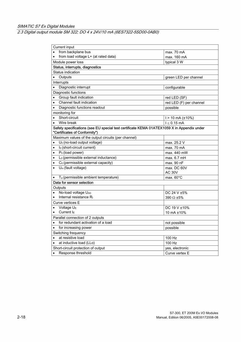
SIMATIC S7 Ex Digital Modules 2.3 Digital output module SM 322; DO 4 x 24V/10 mA (6ES7322-5SD00-0AB0)
S7-300, ET 200M Ex I/O Modules 2-18 Manual, Edition 06/2005, A5E00172008-08
Current input • from backplane bus • from load voltage L+ (at rated data)
max. 70 mA max. 160 mA
Module power loss typical 3 W Status, interrupts, diagnostics Status indication • Outputs green LED per channel Interrupts • Diagnostic interrupt configurable Diagnostic functions • Group fault indication red LED (SF) • Channel fault indication red LED (F) per channel • Diagnostic functions readout possible monitoring for • Short-circuit I > 10 mA (±10%) • Wire break I ≤ 0.15 mA Safety specifications (see EU special test certificate KEMA 01ATEX1059 X in Appendix under "Certificates of Conformity") Maximum values of the output circuits (per channel) • U0 (no-load output voltage) max. 25.2 V • I0 (short-circuit current) max. 70 mA • P0 (load power) max. 440 mW • L0 (permissible external inductance) max. 6.7 mH • C0 (permissible external capacity) max. 90 nF • Um (fault voltage) max. DC 60V
AC 30V • Ta (permissible ambient temperature) max. 60°C Data for sensor selection Outputs • No-load voltage UA0 • Internal resistance RI
DC 24 V ±5% 390 Ω ±5%
Curve vertices E • Voltage UE • Current IE
DC 19 V ±10% 10 mA ±10%
Parallel connection of 2 outputs • for redundant activation of a load not possible • for increasing power possible Switching frequency • at resistive load 100 Hz • at inductive load (LLo) 100 Hz Short-circuit protection of output yes, electronic • Response threshold Curve vertex E

SIMATIC S7 Ex Digital Modules 2.3 Digital output module SM 322; DO 4 x 24V/10 mA (6ES7322-5SD00-0AB0)
S7-300, ET 200M Ex I/O Modules Manual, Edition 06/2005, A5E00172008-08 2-19
Block diagram
IRA
URL
G
Ri
RL
UA
RA
URA
G Ri RL RA UAO UA URL URA U0 I0 IRA
Generator Internal resistor Line resistor Load resistor No-load voltage Output voltage Voltage drop at load resistor Output power at load max. output voltage max. output voltage Load current
Output characteristic
URAURL
IRA
*
UAO
UA
E
IO I
UO
U
Area outside safety limits
Overload(clocked)
Output power at load
E Curve vertice (UE, IE) UE = 19 ± 10% IE = 10 mA ± 10% Output current electronically clocked at overload. Clock ratio ∼ 1:15

SIMATIC S7 Ex Digital Modules 2.3 Digital output module SM 322; DO 4 x 24V/10 mA (6ES7322-5SD00-0AB0)
S7-300, ET 200M Ex I/O Modules 2-20 Manual, Edition 06/2005, A5E00172008-08
See also The LK 393 line chamber (Page 1-5)
Configuration of an S7-300 with Ex I/O Modules (Page 1-8)
Configuration of an ET 200M with Ex I/O modules (Page 1-11)
2.3.2 Parameterization
Parameterization The parameters are set with STEP 7 . You must implement the settings in CPU STOP mode. During transfer from the PG to the S7-300, the parameters set in this way are stored in the CPU and then transferred by the CPU to the digital module.
Alternatively, you can also change several parameters in the user program with SFCs 55 to 57 (see STEP 7-online help).
The parameters for the 2 parameterization alternatives are subdivided into:
• static parameters
• dynamic parameters
The table below shows the characteristics of static and dynamic parameters.
Table 2-8 Static and dynamic parameters
Parameter can be set with CPU operating status static Programming Devices STOP
Programming Devices STOP dynamic SFCs 55 to 57 in user program RUN
Default settings The digital output features default settings for diagnostics, substitute values, etc..
These default settings are applicable when the digital input module has not been parameterized via STEP 7.
Configurable characteristics The characteristics of the SM 322; DO 4 x 24V/10 mA can be parameterized with the following parameter blocks:
• Basic settings
• Diagnostics

SIMATIC S7 Ex Digital Modules 2.3 Digital output module SM 322; DO 4 x 24V/10 mA (6ES7322-5SD00-0AB0)
S7-300, ET 200M Ex I/O Modules Manual, Edition 06/2005, A5E00172008-08 2-21
Channel groups allocation The table below shows the allocation of the 4 channels to the 4 channel groups of digital output.
Table 2-9 Allocation of the 4 channels to the 4 channel groups of SM 322; DO 4 x 24V/10 mA and SM 322; DO 4 x 15V/20 mA
Channel Allocated channel group
Channel 0 Channel group 0 Channel 1 Channel group 1 Channel 2 Channel group 2 Channel 3 Channel group 3
Parameters of the digital output module The table below provides an overview of the parameters and shows what parameters:
• are static or dynamic,
• can be used for the module as a whole or for a channel group.
Table 2-10 Parameters of SM 322; DO 4 x 24V/10 mA and SM 322; DO 4 x 15V/20 mA
SM 322; DO 4 x DC 24V/10 mA / or 15V/20 mA Parameter Range of
values Default Type of Effective range
Basic settings • Enable diagnostic interrupt • retain last valid value • Switch to substitute value • Substitute value
yes/no yes/no yes/no 0 / 1
no no yes 0
dynamic dynamic dynamic dynamic
module module module module
Diagnostics • Short to M • Wire break monitoring 1 • Supply voltage fault
yes/no yes/no yes/no
no no no
static static static
Channel group Channel group Channel group
1 If wire break diagnostic enable is not parameterized there will be no indication by the channel fault LED in the event of a wire break.

SIMATIC S7 Ex Digital Modules 2.3 Digital output module SM 322; DO 4 x 24V/10 mA (6ES7322-5SD00-0AB0)
S7-300, ET 200M Ex I/O Modules 2-22 Manual, Edition 06/2005, A5E00172008-08
2.3.3 Diagnostic messages
Introduction You can use the diagnostic function to determine whether signal output takes place without errors.
Parameterizing diagnostics The diagnostics are parameterized with STEP 7.
Diagnostic evaluation When evaluating the diagnostics, a differentiation must be made between configurable and non-configurable diagnostic messages. In the case of the configurable diagnostic messages (e.g. short to M), diagnostics is only signaled when diagnostic evaluation has been enabled by means of appropriate parameterization (parameter "diagnostics short to M").
Non-configurable diagnostic messages are general, i.e. independent of parameterization.
A diagnostic signal results in a diagnostic interrupt being triggered providing the diagnostic interrupt has been enabled by way of parameterization.
Irrespective of the parameterization, known module errors always result in the SF LED or the corresponding channel fault LED lighting irrespective of the CPU operating status (at POWER ON).
Exception:
The SF LED and the corresponding channel fault LED light in the event of a wire break only when parameterization is enabled.

SIMATIC S7 Ex Digital Modules 2.3 Digital output module SM 322; DO 4 x 24V/10 mA (6ES7322-5SD00-0AB0)
S7-300, ET 200M Ex I/O Modules Manual, Edition 06/2005, A5E00172008-08 2-23
Diagnostics of digital output module The table below provides an overview of the diagnostic messages. You enable diagnostics in STEP 7.
The diagnostic information refers to either the individual channels or the entire module.
Table 2-11 Parameters of SM 322; DO 4 x 24V/10 mA and SM 322; DO 4 x 15V/20 mA
Diagnostic message Effective range of diagnostics configurable Short to M
Wire break
No-load voltage
Channel group
yes
Module not parameterized external auxiliary voltage missing no internal auxiliary voltage Fuse blown Time watchdog tripped EPROM error RAM error CPU error
module
no
Wire break detection A wire break is detected at a current ≤ 0.15 mA.
Reading out diagnostic messages You can read out system diagnostics with STEP 7. You can read detailed diagnostic messages from the module in the user program with SFC 59.

SIMATIC S7 Ex Digital Modules 2.3 Digital output module SM 322; DO 4 x 24V/10 mA (6ES7322-5SD00-0AB0)
S7-300, ET 200M Ex I/O Modules 2-24 Manual, Edition 06/2005, A5E00172008-08
Faults and corrective measures The table below provides a list of possible causes, marginal conditions for fault recognition and corresponding corrective measures for individual diagnostic messages.
Bear in mind that, in order to detect faults which are indicated by means of configurable diagnostic messages, the module must also be parameterized accordingly.
Table 2-12 Diagnostic messages as well as their corrective measures at SM 322; DO 4 x 24V/10 mA and SM 322; DO 4 x 15V/20 mA
Diagnostic message Fault recognition at
Possible fault causes Corrective measures
output overload Eliminate overload Short to M only when output at "1" Short-circuit between the two
output lines Eliminate short-circuit
Break in line between module and actuator
Connect line Wire break only when output at "1"
Channel not used (open) disable channel by parameterization "diagnostics wire break"
No-load voltage only when output at "1"
Failure of internal channel supply voltage
Replace module
Incorrect parameters in module
general Invalid parameters loaded in module by means of SFC
Check parameterization of module and re-load valid parameters
Module not parameterized
general Invalid parameters loaded in module by means of SFC
Check parameterization of module and re-load valid parameters
external auxiliary voltage missing
general No module supply voltage L+ Provide L+ supply
No module supply voltage L+ Provide L+ supply no internal auxiliary voltage
general module-internal fuse defective
Replace module
Fuse blown general module-internal fuse defective
Replace module
partially high electromagnetic interference
Eliminate interference sources and switch CPU supply voltage OFF/ON
Time watchdog tripped EPROM error RAM error CPU error
general
Module defective Replace module

SIMATIC S7 Ex Digital Modules 2.3 Digital output module SM 322; DO 4 x 24V/10 mA (6ES7322-5SD00-0AB0)
S7-300, ET 200M Ex I/O Modules Manual, Edition 06/2005, A5E00172008-08 2-25
2.3.4 Interrupts
Introduction The digital output can trigger a diagnostic interrupt.
Parameterizing interrupts Interrupts are parameterized with STEP 7.
Default setting The interrupts are inhibited by way of default.
Diagnostic interrupt If enabled, the module triggers a diagnostic interrupt when a fault is recognized or is no longer applicable (e.g. short to M). Diagnostic functions inhibited by parameterization cannot trigger an interrupt. The CPU interrupts processing of the user program or low-priority classes and processes the diagnostic interrupt module (OB82).
Influence of supply voltage and operating status The output values are dependent on the supply voltages and CPU operating status.
The table below provides an overview of these dependencies.
Table 2-13 Dependencies of output values on the CPU operating status and supply voltage L+ of SM 322; DO 4 x 24V/10 mA and SM 322; DO 4 x 15V/20 mA
Operating status CPU
Supply voltage L+ at digital module
Output value of the digital module
L+ applied CPU value RUN
No L+ 0 signal
L+ applied Substitute value / last value Substitute value for 0-signal is default setting
POWER ON
STOP
No L+ 0 signal L+ applied 0 signal POWER OFF - No L+ 0 signal
Failure of the supply voltage is always indicated by the SF LED on the front of the module and additionally entered in diagnostics.

SIMATIC S7 Ex Digital Modules 2.4 Digital output module SM 322; DO 4 x 15V/20 mA (6ES7322 5RD00-0AB0)
S7-300, ET 200M Ex I/O Modules 2-26 Manual, Edition 06/2005, A5E00172008-08
2.4 2.4 Digital output module SM 322; DO 4 x 15V/20 mA (6ES7322 5RD00-0AB0)
2.4.1 Features and technical specifications
Order Number 6ES7322-5RD00-0AB0
Features Refer to the description of the digital output module SM 322; DO 4 x 24V/10 mA for the module characteristics.

SIMATIC S7 Ex Digital Modules 2.4 Digital output module SM 322; DO 4 x 15V/20 mA (6ES7322 5RD00-0AB0)
S7-300, ET 200M Ex I/O Modules Manual, Edition 06/2005, A5E00172008-08 2-27
Terminal diagram of the SM 322; DO 4 x 15V/20 mA
1
2
3
4
5
6
7
8
910
12
13 CH2
CH0
CH3
CH1
14
15
16
17
18
19
20
11
L +
M
SF
F0
F1
F2
F3
0
1
2
3
[EEx ib] IIC
x x
X 23 4
322-5RD00-0AB0
SM 322DO4 x DC15V/20mA
Channel number
0...3 status indication [green]
SF Group error indicator [red]F (0...3) channel-specific fault indication [red]
Terminal diagram
Output 0
Output 1
Output 2
Output 3
Figure 2-5 Terminal diagram of the SM 322; DO 4 x 15V/20 mA
Notes on intrinsically-safe installation You must connect the DM 370 dummy module between the CPU or IM 153 (in a distributed configuration) and the Ex I/O modules whose signal cables lead into the hazardous location. In a distributed configuration with an active backplane bus, you should use the ex dividing panel/ex barrier instead of the dummy module.
Power supply for an intrinsically-safe structure In order to maintain the clearances and creepage distances, L+/M must be routed via the line chamber LK393 when operating modules with signal cables that lead to the hazardous location.
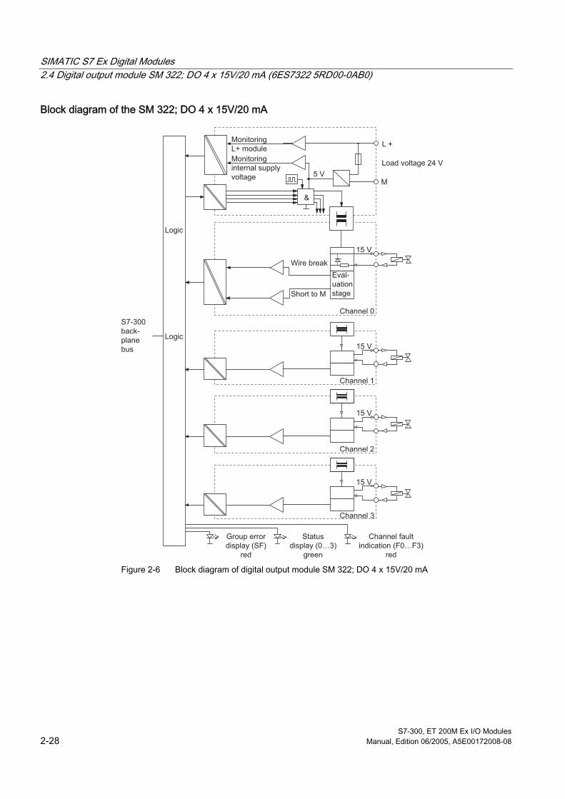
SIMATIC S7 Ex Digital Modules 2.4 Digital output module SM 322; DO 4 x 15V/20 mA (6ES7322 5RD00-0AB0)
S7-300, ET 200M Ex I/O Modules 2-28 Manual, Edition 06/2005, A5E00172008-08
Block diagram of the SM 322; DO 4 x 15V/20 mA
L +
M
15 V
15 V
15 V
&
5 V
15 V
Wire break
Channel 3
Channel 2
Channel 1
Logic
Logic
S7-300 back-plane bus
Channel 0
Load voltage 24 V
Short to M
MonitoringL+ moduleMonitoringinternal supply voltage
Eval-uation stage
Channel fault indication (F0…F3)
red
Statusdisplay (0…3)
green
Group errordisplay (SF)
red Figure 2-6 Block diagram of digital output module SM 322; DO 4 x 15V/20 mA
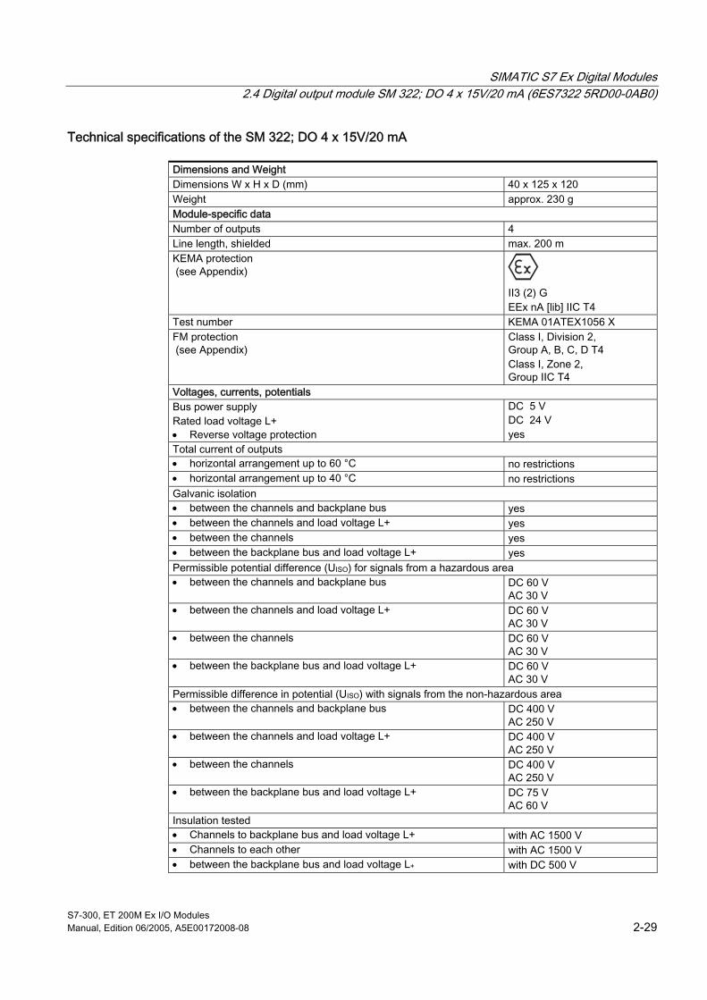
SIMATIC S7 Ex Digital Modules 2.4 Digital output module SM 322; DO 4 x 15V/20 mA (6ES7322 5RD00-0AB0)
S7-300, ET 200M Ex I/O Modules Manual, Edition 06/2005, A5E00172008-08 2-29
Technical specifications of the SM 322; DO 4 x 15V/20 mA
Dimensions and Weight Dimensions W x H x D (mm) 40 x 125 x 120 Weight approx. 230 g Module-specific data Number of outputs 4 Line length, shielded max. 200 m KEMA protection (see Appendix)
II3 (2) G EEx nA [lib] IIC T4
Test number KEMA 01ATEX1056 X FM protection (see Appendix)
Class I, Division 2, Group A, B, C, D T4 Class I, Zone 2, Group IIC T4
Voltages, currents, potentials Bus power supply Rated load voltage L+ • Reverse voltage protection
DC 5 V DC 24 V yes
Total current of outputs • horizontal arrangement up to 60 °C no restrictions • horizontal arrangement up to 40 °C no restrictions Galvanic isolation • between the channels and backplane bus yes • between the channels and load voltage L+ yes • between the channels yes • between the backplane bus and load voltage L+ yes Permissible potential difference (UISO) for signals from a hazardous area • between the channels and backplane bus DC 60 V
AC 30 V • between the channels and load voltage L+ DC 60 V
AC 30 V • between the channels DC 60 V
AC 30 V • between the backplane bus and load voltage L+ DC 60 V
AC 30 V Permissible difference in potential (UISO) with signals from the non-hazardous area • between the channels and backplane bus DC 400 V
AC 250 V • between the channels and load voltage L+ DC 400 V
AC 250 V • between the channels DC 400 V
AC 250 V • between the backplane bus and load voltage L+ DC 75 V
AC 60 V Insulation tested • Channels to backplane bus and load voltage L+ with AC 1500 V • Channels to each other with AC 1500 V • between the backplane bus and load voltage L+ with DC 500 V

SIMATIC S7 Ex Digital Modules 2.4 Digital output module SM 322; DO 4 x 15V/20 mA (6ES7322 5RD00-0AB0)
S7-300, ET 200M Ex I/O Modules 2-30 Manual, Edition 06/2005, A5E00172008-08
Current input • from backplane bus • from load voltage L+ (at rated data)
max. 70 mA max. 160 mA
Module power loss typical 3 W Status, interrupts, diagnostics Status indication • Outputs green LED per channel Interrupts • Diagnostic interrupt configurable Diagnostic functions • Group fault indication red LED (SF) • Channel fault indication red LED (F) per channel • Diagnostic functions readout possible monitoring for • Short-circuit I > 20,5 mA (±10%) • Wire break I ≤ 0.15 mA Safety specifications (see EU special test certificate KEMA 01ATEX1056 X in Appendix under "Certificates of Conformity") Maximum values of the output circuits (per channel) • U0 (no-load output voltage) max.15.75 V • I0 (short-circuit current) max. 85 mA • P0 (load power) max. 335 mW • L0 (permissible external inductance) max. 5 mH • C0 (permissible external capacity) max. 478 nF • Um (fault voltage) max. DC 60V
AC 30V • Ta (permissible ambient temperature) max. 60°C Data for sensor selection Outputs • No-load voltage UA0 • Internal resistance RI
DC 15 V ±5% 200 Ω ±5%
Curve vertices E • Voltage UE • Current IE
DC 10 V ±10% 20.5 mA ±10%
Parallel connection of 2 outputs • for redundant activation of a load not possible • for increasing power possible Switching frequency • at resistive load 100 Hz • at inductive load (L < Lo) 100 Hz Short-circuit protection of output yes, electronic • Response threshold Curve vertex E

SIMATIC S7 Ex Digital Modules 2.4 Digital output module SM 322; DO 4 x 15V/20 mA (6ES7322 5RD00-0AB0)
S7-300, ET 200M Ex I/O Modules Manual, Edition 06/2005, A5E00172008-08 2-31
Block diagram
IRA
URL
G
Ri
RL
UA
RA
URA
G Ri RL RA UAO UA URL URA U0 I0 IRA
Generator Internal resistance Line resistor Load resistor No-load voltage Output voltage Voltage drop at load resistor Output power at load max. output voltage max. output voltage Load current
Output characteristic
URAURL
IRA
*
UAO
UA
E
IO I
UO
U
Area outside safety limits
Overload(clocked)
Output power at load E Curve vertice (UE, IE)
UE = 10 V ± 10% IE = 20.5 mA ± 10% Output current electronically clocked at overload. Clock ratio ∼ 1:15
See also The LK 393 line chamber (Page 1-5)
Configuration of an S7-300 with Ex I/O Modules (Page 1-8)
Configuration of an ET 200M with Ex I/O modules (Page 1-11)

SIMATIC S7 Ex Digital Modules 2.4 Digital output module SM 322; DO 4 x 15V/20 mA (6ES7322 5RD00-0AB0)
S7-300, ET 200M Ex I/O Modules 2-32 Manual, Edition 06/2005, A5E00172008-08

S7-300, ET 200M Ex I/O Modules Manual, Edition 06/2005, A5E00172008-08 3-1
SIMATIC S7 Ex Analog Modules 33.1 3.1 Analog value representation
3.1.1 Analog Value Representation of Analog Input and Output Values
Conversion of analog values The CPU processes the analog values only in binary form.
Analog input modules convert the analog process signal into digital form.
Analog output modules convert the digital output value into an analog signal.
Analog value representation The digitized analog value is the same for both input and output values with the same rated range.
The analog values are represented as two's complement.
Table 3-1 Characteristics of Analog Modules
Resolution Analog value Bit number 15 14 13 12 11 10 9 8 7 6 5 4 3 2 1 0 Bit significance sign 214 213 212 211 210 29 28 27 26 25 24 23 22 21 20
Sign The sign of the analog value is always in bit number 15:
• "0" → +
• "1" → -

SIMATIC S7 Ex Analog Modules 3.1 Analog value representation
S7-300, ET 200M Ex I/O Modules 3-2 Manual, Edition 06/2005, A5E00172008-08
3.1.2 Analog Representation for Measuring Ranges of Analog Inputs
Introduction The tables in this section indicate the digitized analog values for the effective measuring ranges of analog modules.
Reading measured value tables The tables for analog value representation for the measuring ranges of the analog inputs include the digitized analog values for the differing measuring ranges.
Since the binary representation of analog values is always the same, these tables contain only a comparison of the measuring ranges with respect to the relevant units.
Measured value resolution Deviating from this, a Sigma Delta AD converter is used with the analog input modules described in the manual. Irrespective of the configurable integration time, this converter always makes available the maximum representable 15 Bit +sign. Lower resolution ratings than indicated in the specifications are due to conversion noise based on the shorter integration times (2.5, 16/2/3, 20 ms). The different integration times change nothing with regard to numerical representation of the measured values. The number of stable bits is specified in the technical specifications.
The number of stable bits is the resolution at which, despite noise, the "no missing code"characteristics of the AD converter are guaranteed.
The bits that are no longer stable at shorter integration times are marked with "x" in the following tables.
Table 3-2 Representation of the smallest stable unit of the analog value
Smallest stable unit Analog value Stable bits (+ sign) Decimal Hexadecimal High-Byte Low-Byte
9 64 40H Sign 0 0 0 0 0 0 0 0 1 x x x x x x 10 32 20H Sign 0 0 0 0 0 0 0 0 0 1 x x x x x 12 8 8H Sign 0 0 0 0 0 0 0 0 0 0 0 1 x x x 13 4 4H Sign 0 0 0 0 0 0 0 0 0 0 0 0 1 x x 15 1 1H Sign 0 0 0 0 0 0 0 0 0 0 0 0 0 0 1

SIMATIC S7 Ex Analog Modules 3.1 Analog value representation
S7-300, ET 200M Ex I/O Modules Manual, Edition 06/2005, A5E00172008-08 3-3
Noise-prone bits At a constant input voltage, noise causes distribution of the supplied value by more than ± 1 digit. In the majority of cases, these "unsteady" values can be used as they are. In any case, this is the most effective option when subsequent processing has integral action characteristics (integrator, controller, etc.) in any form whatsoever. If this "unsteady state" is undesirable (e.g. for displays), you can
• mask out the "x" bits
• round up to "stable" bits
• filter the successive values
With these options you must first ensure by way of interrogation that you will not change the coding for invalid measured values (-32768 / 8000H and 32767/7FFFH) or you incorporate it in the filtering process.
3.1.3 Analog value representation for the voltage measuring ranges
Voltage measuring ranges ± 25 mV, ± 50 mV, ± 80 mV, ± 250 mV, ± 500 mV and ± 1 V.
Table 3-3 Representation of the digitized measured value of an analog input module (voltage measuring ranges)
Measuring ranges Units ± 25 mV ± 50 mV ± 80 mV ± 250 mV ± 500 mV ± 1 V deci-
mal hexa-
decimal
Location
> 29,397 > 58,794 > 94,071 >293,96 >587,94 > 1,1750 32767 7FFFH Overflow 29,397 58,794 94,071 293,96 587,94 1,1750 32511 7EFFH : : : : : : : : 25,001 50,002 80,003 250,02 500,02 1,0001 27649 6C01H
Over-range
25,000 50,000 80,000 250,00 500,00 1,0000 27648 6C00H 18,750 37,500 60,000 187,50 375,00 0,7500 20736 5100H : : : : : : : : - 18,750 - 37,500 - 60,000 - 187,50 - 375,00 0,7500 -20736 AF00H - 25,000 - 50,000 - 80,000 - 250,00 - 500,00 - 1,0000 -27648 9400H
Rated range
- 25,001 - 50,002 - 80,003 - 250,01 - 500,02 - 1,0001 -27649 93FFH : : : : : : : : - 29,398 - 58,796 - 94,074 - 293,98 - 587,96 - 1,1750 -32512 8100H
Under-range
<- 29,398 <- 58,796 <- 94,074 <- 293,98 <- 587,96 <- 1,1750 -32768 8000H Under-flow

SIMATIC S7 Ex Analog Modules 3.1 Analog value representation
S7-300, ET 200M Ex I/O Modules 3-4 Manual, Edition 06/2005, A5E00172008-08
3.1.4 Analog value representation for the current measuring ranges
Current measuring range from 0 to 20 mA from 4 to 20 mA
Table 3-4 Representation of the digitized measured value of analog input module SM 331; AI 4 x0/4...20 mA and AI 2 x 0/4...20 mA HART
Units Measuring range from
0 to 20 mA
Measuring range from
4 to 20 mA
decimal hexa-decimal
Location
> 23,515 >22,810 32767 7FFFH Overflow 23,515 22,810 32511 7EFFH
: : : : 20,0007 20,0005 27649 6C01H
Overrange
20,000 20,000 27648 6C00H 14,998 16,000 20736 5100H
: : : : 0,0 4,000 0 0H
Rated range
<0,0 2 3,9995 -1 FFFFH 3,800 -345 FEA7H 3,600 -691 FD4DH Wire break limit I ≦ 3.60 mA in accordance
with NAMUR 1 : : : Underrange
1,1852 -4864 ED00H <1,1852 32767 7FFFH Underflow 1 NAMUR limits are evaluated only if wire break diagnostics is enabled. When wire break diagnostics is enabled, 7FFFH is output if the current value drops below 3.6 mA. If the value increases again to above 3.8 mA, the wire break signal is canceled and the current value is output again. 2 Negative measured values cannot be recorded. In the event of analog values < 0 mA, the relevant representation of the digital measured value of 0 mA is retained.

SIMATIC S7 Ex Analog Modules 3.1 Analog value representation
S7-300, ET 200M Ex I/O Modules Manual, Edition 06/2005, A5E00172008-08 3-5
3.1.5 Analog value representation for measuring ranges of the resistance sensor
Resistance sensor with measuring ranges 150 Ω, 300 Ω and 600 Ω
Table 3-5 Representation of the digitized measured value of an analog input module (resistance sensor)
Units Measuring range 150 Ω
Measuring range 300 Ω
Measuring range 600 Ω deci-
mal hexa-
decimal
Location
> 176,383 > 352,767 > 705,534 32767 7FFFH Overflow 176,383 352,767 705,534 32511 7EFFH
: : : : : 150,005 300,011 600,022 27649 6C01H
Overrange 1
150,000 300,000 600,000 27648 6C00H 112,500 225,000 450,000 20736 5100H
: : : : : 0,000 0,000 0,000 0 0H
Rated range
(negative values physically not possible) 1 The same degree of accuracy as in the rated range is guaranteed in the overrange.

SIMATIC S7 Ex Analog Modules 3.1 Analog value representation
S7-300, ET 200M Ex I/O Modules 3-6 Manual, Edition 06/2005, A5E00172008-08
3.1.6 Analog value representation for the standard temperature range
Standard temperature range of the sensor Pt 100, Pt 200 in accordance with DIN 43760 and IEC 751
Table 3-6 Representation of the digitized measured value of an analog input module (temperature range, standard; Pt 100, Pt 200)
Standard temperature range 850 °C
Pt 100, Pt 200 in °C
decimal hexadecimal Location
> 1300,0 32767 7FFFH Overflow 1300,0
: 850,1
13000 :
8501
32C8H :
2135H
Overrange 1
850,0 :
-200,0
8500 :
-2000
2134H :
F830H
Rated range
-200,1 :
-240,0
-2001 :
-2400
F82FH :
F6A0H
Overrange 2
< -240,0 -32768 8000H Underflow 1 The characteristic of the Pt 100, Pt 200 sensor is not defined in the overrange. The overrange has been extended to 1300°C in order to be able to incorporate future technical developments of platinum thermal resistors (thermistors). It is not possible to specify the accuracy of this range. 2 The characteristic of the Pt 100, Pt 200 sensor is not defined in the overrange. The rise of the characteristic curve is retained on leaving the linearized rated range. It is not possible to specify the accuracy of this range.

SIMATIC S7 Ex Analog Modules 3.1 Analog value representation
S7-300, ET 200M Ex I/O Modules Manual, Edition 06/2005, A5E00172008-08 3-7
3.1.7 Analog value representation for the climatic temperature range
Climatic temperature range of the sensor Pt 100, Pt 200 in accordance with DIN 43760 and IEC 751
Table 3-7 Representation of the digitized measured value of an analog input module (climatic temperature range; Pt 100, Pt 200)
Climatic temperature range
Pt 100, Pt 200 in °C
decimal hexadecimal Location
> 325,12 32767 7FFFH Overflow 325,12
: 276,49
32512 :
27649
7F00H :
6C01H
Overrange 1
276,48 :
-200,00
27648 :
-20000
6C00H :
B1E0
Rated range
-200,01 :
-240,00
-20001 :
-24000
B1E1 :
A240H
Overrange 2
< - 240,00 -32768 8000H Underflow 1 The same degree of accuracy as in the rated range is guaranteed in the overrange Pt 100, Pt 200 climatic. 2The characteristic of the Pt 100, Pt 200 sensor is not defined in the overrange. The rise of the characteristic curve is retained on leaving the linearized rated range. It is not possible to specify the accuracy of these ranges.

SIMATIC S7 Ex Analog Modules 3.1 Analog value representation
S7-300, ET 200M Ex I/O Modules 3-8 Manual, Edition 06/2005, A5E00172008-08
3.1.8 Analog value representation for the standard temperature range Ni 100
Standard temperature range Ni 100 in accordance with DIN 43760
Table 3-8 Representation of the digitized measured value of an analog input module (standard temperature range, Ni 100)
Temperature range standard Ni 100 in °C
decimal hexadecimal Location
> 295,0 32767 7FFFH Overflow 295,0
: 250,1
2950 :
2501
686H :
9C5H
Overrange 1
250,0 :
-60,0
2500 :
-600
9C4H :
FDA8H
Rated range
-60,1 :
-105,0
-601 :
-1050
FDA7H :
FF97H
Overrange 1
< - 105,0 -32768 8000H Underflow 1 The characteristic of the Ni 100 sensor is not defined in the overrange and underrange. The rise of the characteristic curve is retained on leaving the linearized rated range. It is not possible to specify the accuracy of these ranges.

SIMATIC S7 Ex Analog Modules 3.1 Analog value representation
S7-300, ET 200M Ex I/O Modules Manual, Edition 06/2005, A5E00172008-08 3-9
3.1.9 Analog value representation for the climatic temperature range Ni 100
Climatic temperature range Ni 100 in accordance with DIN 43760 The same value range as in the standard range of the Ni 100 sensor applies in the climatic range Ni 100 only with a higher resolution of 0.01_C instead of 0.1 _C.
Table 3-9 Representation of the digitized measured value of an analog input module (climatic temperature range, Ni 100)
Climatic temperature range Ni 100 in °C
decimal hexadecimal Location
> 295,00 32767 7FFFH Overflow 295,00
: 250,01
29500 :
25001
733CH :
61A9H
Overrange 1
250,00 :
-60,00
25000 :
-6000
61A8H :
E890H
Rated range
-60,01 :
-105,00
-6001 :
-10500
E88FH :
D6FCH
Overrange 1
< - 105,00 -32768 8000H Underflow 1 The characteristic of the Ni 100 sensor is not defined in the overrange and underrange. The rise of the characteristic curve is retained on leaving the linearized rated range. It is not possible to specify the accuracy of these ranges.

SIMATIC S7 Ex Analog Modules 3.1 Analog value representation
S7-300, ET 200M Ex I/O Modules 3-10 Manual, Edition 06/2005, A5E00172008-08
3.1.10 Analog value representation for the temperature range type T
Temperature range sensor type T The basic thermal e.m.f. values specified in the following comply with DIN IEC 584.
Table 3-10 Representation of the digitized measured value of an analog input module (temperature range, type T)
Temperature range in °C
decimal hexadecimal Location
> 540,0 32767 7FFFH Overflow 540,0
: 400,1
5400 :
4001
1518H :
0FA1H
Overrange 2
400,0 : :
-230,0 1) :
-270,0
4000 : :
-2300 :
-2700
0FA0H : :
F704H :
F574H
Rated range
≦-270,1 ≦-2701 ≦F573H Overrange 2 In the case of incorrect wiring (e.g. polarity reversal, open inputs) or a sensor fault in the negative range (e.g. incorrect type of thermocouple), when dropping below F0C4H the analog input module signals underflow and outputs 8000H. 1 The module linearizes the range from +400 to -230 °C for type T. Below -230 °C, the rise of the characteristic curve decreases to such an extent that, from this point, precision evaluation is no longer possible. The rise in the characteristic curve at this point is retained until underrange is reached. 2 The characteristic of the thermocouple is not defined in the overrange and underrange. The rise of the characteristic curve is retained on leaving the linearized range. It is not possible to specify the accuracy of these ranges.

SIMATIC S7 Ex Analog Modules 3.1 Analog value representation
S7-300, ET 200M Ex I/O Modules Manual, Edition 06/2005, A5E00172008-08 3-11
3.1.11 Analog value representation for the temperature range type U
Temperature range sensor type U The basic thermal e.m.f. values specified in the following comply with DIN IEC 584.
Table 3-11 Representation of the digitized measured value of an analog input module (temperature range, type U)
Temperature range in °C
decimal hexadecimal Location
> 850,0 32767 7FFFH Overflow 850,0
: 600,1
8500 :
6001
2134H :
0FA1H
Overrange 1
600,0 : :
-200,0
6000 : :
-2000
0FA0H : :
F830H
Rated range
≦-200,1 ≦-2001 ≦F82FH Overrange 1 In the case of incorrect wiring (e.g. polarity reversal, open inputs) or a sensor fault in the negative range (e.g. incorrect type of thermocouple), when dropping below F380H the analog input module signals underflow and outputs 8000H. 1 The characteristic of the thermocouple is not defined in the overrange and underrange. The rise of the characteristic curve is retained on leaving the linearized range. It is not possible to specify the accuracy of these ranges.

SIMATIC S7 Ex Analog Modules 3.1 Analog value representation
S7-300, ET 200M Ex I/O Modules 3-12 Manual, Edition 06/2005, A5E00172008-08
3.1.12 Analog value representation for the temperature range type E
Temperature range sensor type E The basic thermal e.m.f. values specified in the following comply with DIN IEC 584.
Table 3-12 Representation of the digitized measured value of an analog input module (temperature range, type E)
Temperature range in °C
decimal hexadecimal Location
> 1200,0 32767 7FFFH Overflow 1200,0
: 1000,1
12000 :
10001
2EE0H :
2711H
Overrange 2
1000,0 : :
-150,01 :
-270,0
10000 : :
-1500 :
-2700
2710H : :
FA24H :
F574H
Rated range
≦-270,1 ≦-2701 ≦F573H Overrange 2 In the case of incorrect wiring (e.g. polarity reversal, open inputs) or a sensor fault in the negative range (e.g. incorrect type of thermocouple), when dropping below F0C4H the analog input module signals underflow and outputs 8000H. 1 The module linearizes the range from +1000 to -150°C for type E. Below -150°C, the rise of the characteristic curve decreases to such an extent that, from this point, precision evaluation is no longer possible. The rise in the characteristic curve at this point is retained until underrange is reached. 2 The characteristic of the thermocouple is not defined in the overrange and underrange. The rise of the characteristic curve is retained on leaving the linearized range. It is not possible to specify the accuracy of these ranges.
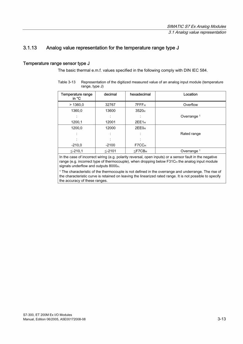
SIMATIC S7 Ex Analog Modules 3.1 Analog value representation
S7-300, ET 200M Ex I/O Modules Manual, Edition 06/2005, A5E00172008-08 3-13
3.1.13 Analog value representation for the temperature range type J
Temperature range sensor type J The basic thermal e.m.f. values specified in the following comply with DIN IEC 584.
Table 3-13 Representation of the digitized measured value of an analog input module (temperature range, type J)
Temperature range in °C
decimal hexadecimal Location
> 1360,0 32767 7FFFH Overflow 1360,0
: 1200,1
13600 :
12001
3520H :
2EE1H
Overrange 1
1200,0 : :
-210,0
12000 : :
-2100
2EE0H : :
F7CCH
Rated range
≦-210,1 ≦-2101 ≦F7CBH Overrange 1 In the case of incorrect wiring (e.g. polarity reversal, open inputs) or a sensor fault in the negative range (e.g. incorrect type of thermocouple), when dropping below F31CH the analog input module signals underflow and outputs 8000H. 1 The characteristic of the thermocouple is not defined in the overrange and underrange. The rise of the characteristic curve is retained on leaving the linearized rated range. It is not possible to specify the accuracy of these ranges.

SIMATIC S7 Ex Analog Modules 3.1 Analog value representation
S7-300, ET 200M Ex I/O Modules 3-14 Manual, Edition 06/2005, A5E00172008-08
3.1.14 Analog value representation for the temperature range type L
Temperature range sensor type L The basic thermal e.m.f. values specified in the following comply with DIN IEC 584.
Table 3-14 Representation of the digitized measured value of an analog input module (temperature range, type L)
Temperature range in °C
decimal hexadecimal Location
> 1150,0 32767 7FFFH Overflow 1150,0
: 900,1
13500 :
9001
2CECH :
2329H
Overrange 1
900,0 : :
-200,0
9000 : :
-2000
2328H : :
F830H
Rated range
≦-200,1 ≦-2001 ≦F82FH Overrange 1 In the case of incorrect wiring (e.g. polarity reversal, open inputs) or a sensor fault in the negative range (e.g. incorrect type of thermocouple), when dropping below F380H the analog input module signals underflow and outputs 8000H. 1 The characteristic of the thermocouple is not defined in the overrange and underrange. The rise of the characteristic curve is retained on leaving the linearized rated range. It is not possible to specify the accuracy of these ranges.

SIMATIC S7 Ex Analog Modules 3.1 Analog value representation
S7-300, ET 200M Ex I/O Modules Manual, Edition 06/2005, A5E00172008-08 3-15
3.1.15 Analog value representation for the temperature range type K
Temperature range sensor type K The basic thermal e.m.f. values specified in the following comply with DIN IEC 584.
Table 3-15 Representation of the digitized measured value of an analog input module (temperature range, type K)
Temperature range in °C
decimal hexadecimal Location
> 1622,0 32767 7FFFH Overflow 1622,0
: 1372,1
16220 :
13721
3F5CH :
3599H
Overrange 2
1372,0 : :
-220,01 :
-270,0
13720 : :
-2200 :
-2700
3598H : :
F768H :
F574H
Rated range
≦-270,1 ≦-2701 ≦F573H Overrange 2 In the case of incorrect wiring (e.g. polarity reversal, open inputs) or a sensor fault in the negative range (e.g. incorrect type of thermocouple), when dropping below F0C4H the analog input module signals underflow and outputs 8000H. 1 The module linearizes the range from +1372 to -220°C for type K. Below -220°C, the rise of the characteristic curve decreases to such an extent that, from this point, precision evaluation is no longer possible. The rise in the characteristic curve at this point is retained until underrange is reached. 2 The characteristic of the thermocouple is not defined in the overrange and underrange. The rise of the characteristic curve is retained on leaving the rated range. It is not possible to specify the accuracy of these ranges.
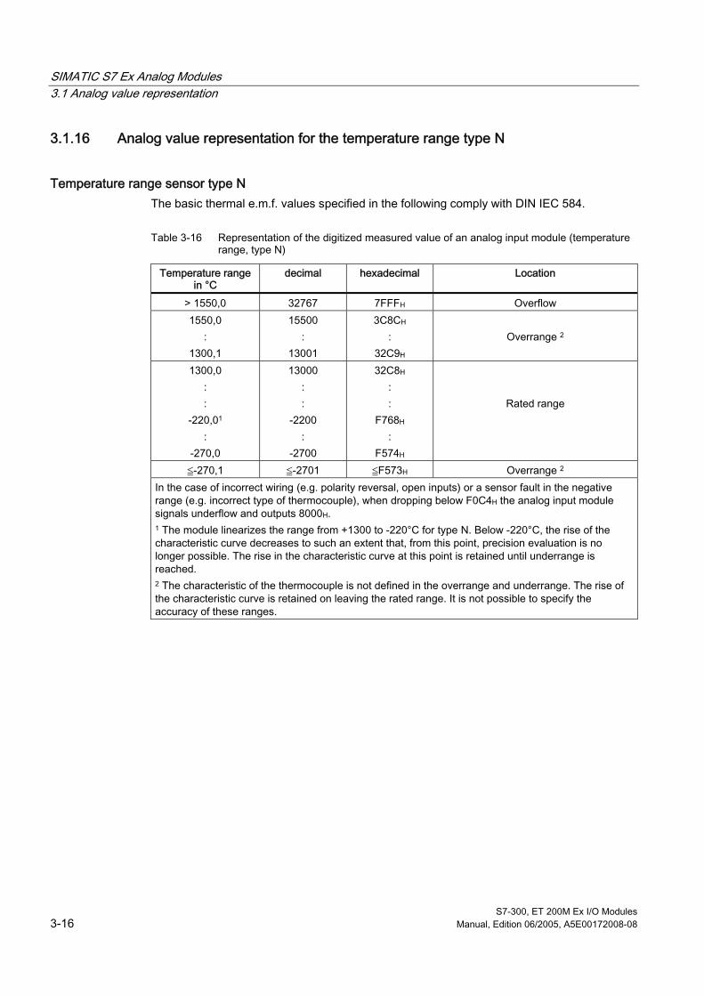
SIMATIC S7 Ex Analog Modules 3.1 Analog value representation
S7-300, ET 200M Ex I/O Modules 3-16 Manual, Edition 06/2005, A5E00172008-08
3.1.16 Analog value representation for the temperature range type N
Temperature range sensor type N The basic thermal e.m.f. values specified in the following comply with DIN IEC 584.
Table 3-16 Representation of the digitized measured value of an analog input module (temperature range, type N)
Temperature range in °C
decimal hexadecimal Location
> 1550,0 32767 7FFFH Overflow 1550,0
: 1300,1
15500 :
13001
3C8CH :
32C9H
Overrange 2
1300,0 : :
-220,01 :
-270,0
13000 : :
-2200 :
-2700
32C8H : :
F768H :
F574H
Rated range
≦-270,1 ≦-2701 ≦F573H Overrange 2 In the case of incorrect wiring (e.g. polarity reversal, open inputs) or a sensor fault in the negative range (e.g. incorrect type of thermocouple), when dropping below F0C4H the analog input module signals underflow and outputs 8000H. 1 The module linearizes the range from +1300 to -220°C for type N. Below -220°C, the rise of the characteristic curve decreases to such an extent that, from this point, precision evaluation is no longer possible. The rise in the characteristic curve at this point is retained until underrange is reached. 2 The characteristic of the thermocouple is not defined in the overrange and underrange. The rise of the characteristic curve is retained on leaving the rated range. It is not possible to specify the accuracy of these ranges.

SIMATIC S7 Ex Analog Modules 3.1 Analog value representation
S7-300, ET 200M Ex I/O Modules Manual, Edition 06/2005, A5E00172008-08 3-17
3.1.17 Analog value representation for the temperature range type R
Temperature range sensor type R The basic thermal e.m.f. values specified in the following comply with DIN IEC 584.
Table 3-17 Representation of the digitized measured value of an analog input module (temperature range, type R)
Temperature range in °C
decimal hexadecimal Location
> 2019,0 32767 7FFFH Overflow 2019,0
: 1769,1
20190 :
17691
4EDEH :
451BH
Overrange 1
1769,0 : :
-50,0
17690 : :
-500
451AH : :
FE0CH
Rated range
-50,1 :
-170,0
-501 :
-1700
FE0BH :
F95CH
Overrange 1
< -170,0 -32768 8000H Underflow In the case of incorrect wiring (e.g. polarity reversal, open inputs) or a sensor fault in the negative range (e.g. incorrect type of thermocouple), when dropping below F95CH the analog input module signals underflow and outputs 8000H. 1 The characteristic of the thermocouple is not defined in the overrange and underrange. The rise of the characteristic curve is retained on leaving the linearized rated range. It is not possible to specify the accuracy of these ranges.

SIMATIC S7 Ex Analog Modules 3.1 Analog value representation
S7-300, ET 200M Ex I/O Modules 3-18 Manual, Edition 06/2005, A5E00172008-08
3.1.18 Analog value representation for the temperature range type S
Temperature range sensor type S The basic thermal e.m.f. values specified in the following comply with DIN IEC 584.
Table 3-18 Representation of the digitized measured value of an analog input module (temperature range, type S)
Temperature range in °C
decimal hexadecimal Location
> 1850,0 32767 7FFFH Overflow 1850,0
: 1769,1
18500 :
17691
4844H :
451BH
Overrange 1
1769,0 : :
-50,0
17690 : :
-500
451AH : :
FE0CH
Rated range
-50,1 :
-170,0
-501 :
-1700
FE0BH :
F95CH
Overrange 1
< -170,0 -32768 8000H Underflow In the case of incorrect wiring (e.g. polarity reversal, open inputs) or a sensor fault in the negative range (e.g. incorrect type of thermocouple), when dropping below F95CH the analog input module signals underflow and outputs 8000H. 1 The characteristic of the thermocouple is not defined in the overrange and underrange. The rise of the characteristic curve is retained on leaving the linearized range. It is not possible to specify the accuracy of these ranges.

SIMATIC S7 Ex Analog Modules 3.1 Analog value representation
S7-300, ET 200M Ex I/O Modules Manual, Edition 06/2005, A5E00172008-08 3-19
3.1.19 Analog value representation for the temperature range type B
Temperature range sensor type B The basic thermal e.m.f. values specified in the following comply with DIN IEC 584.
Table 3-19 Representation of the digitized measured value of an analog input module (temperature range, type B)
Temperature range in °C
Type B
decimal hexadecimal Location
> 2070,0 32767 7FFFH Overflow 2070,0
: 1820,1
20700 :
18201
50DCH :
4719H
Overrange 2
1820,0 : :
200,01 :
0,0
18200 : :
2000 : 0
4718H : :
7D0H :
0H
Rated range
-0,1 :
-150,0
-1 :
-1500
FFFFH :
FF24H
Overrange 2
< -150,0 -32768 8000H Underflow In the case of incorrect wiring (e.g. polarity reversal, open inputs) or a sensor fault in the negative range (e.g. incorrect type of thermocouple), when dropping below FA24H the analog input module signals underflow and outputs 8000H. 1 The module linearizes the range from +1820 to +200°C for type B. Below +200°C, the rise of the characteristic curve decreases to such an extent that, from this point, precision evaluation is no longer possible. The rise in the characteristic curve at this point is retained until underrange is reached. The characteristic curve of the type B thermocouple does not feature monotone characteristics in the temperature range between 0 and 40°C. Measured values from this range are not distinctly allocated to a specific temperature. 2 The characteristic of the thermocouple is not defined in the overrange and underrange. The rise of the characteristic curve is retained on leaving the linearized range. It is not possible to specify the accuracy of these ranges.

SIMATIC S7 Ex Analog Modules 3.1 Analog value representation
S7-300, ET 200M Ex I/O Modules 3-20 Manual, Edition 06/2005, A5E00172008-08
3.1.20 Analog Value Representation for the Output Ranges of Analog Outputs
Current output ranges from 0 to 20 mA and 4 to 20 mA
Table 3-20 Representation of analog output range of analog output modules (current output ranges)
Units Location Output range
0 to 20 mA
Output range
4 to 20 mA decimal hexa-
decimal
0,0 0,0 ≥32512 ≥7F00H Overflow 23,515 22,81 32511 7EFFH
: : : : 20,0007 20,005 27649 6C01H
Overrange
20,000 20,000 27648 6C00H : : : :
0,0 4,000 0 0H Rated range
0,0 -1 FFFFH
3,9995 : : :
0,0 - 6912 E500H Underrange
0,0 - 6913 E4FFH : : - 32768 8000H
Underflow
Note with the analog output SM 332; AO 4 x 0/4... 20 mA the linearity can decrease in the overrange at load resistances > 425 Ω.

SIMATIC S7 Ex Analog Modules 3.2 General information on connection technology
S7-300, ET 200M Ex I/O Modules Manual, Edition 06/2005, A5E00172008-08 3-21
3.2 3.2 General information on connection technology
Abbreviations used The following diagrams show the different connection possibilities of sensors. The abbreviations used in the diagrams have the following meanings:
Abbreviation Meaning IC+ Positive connection of the constant current output IC- Negative connection of the constant current output M+ M+ :Measuring line (positive) M- Measuring line (negative) UISO Differences in potential between inputs and ground terminal M UCM Differences in potential between inputs L + 24 V DC power supply connection M Ground terminal for 24 V DC power supply P5V Supply voltage of module logic Minternal Ground of module logic UV Isolated supply voltage for compensation box L0+ ... L3+ Isolated transducer supply per channel UM Measuring-circuit voltage RS Measuring shunt UV+; UV- External transducer supply voltage QI0- ... QI3- Analog outputs current (output current) M0- ... M3- Reference potential of the analog output circuit RL Resistance of the load/actuator UISO Difference in potential between the reference points of the channels
M0- ... M3- or between the channels and M- terminal of the CPU.
See also Connecting transducers to analog inputs (Page 3-22)
Connecting thermocouples to the analog input SM 331; AI 8 x TC/4 x RTD (Page 3-25)
Connection of resistance thermometers (e.g. Pt100) and resistance sensors (Page 3-30)
SIMATIC S7 Ex Analog Modules 3.3 Connecting transducers to analog inputs
S7-300, ET 200M Ex I/O Modules 3-22 Manual, Edition 06/2005, A5E00172008-08
3.3 3.3 Connecting transducers to analog inputs
Transducer Depending on the measurement mode, various transducers can be connected to analog input modules:
• Voltage sensor
• Current sensor as
– 2-wire measuring transducer
– 4-wire measuring transducer
• Resistance sensor
Lines for analog signals Shielded conductors twisted in pairs are used for the analog signals.
Isolated analog input modules In the isolated analog input modules there is no metallic connection between M- of the measuring circuit and the M- terminal of the CPU.
Isolated analog input modules are used when there is to be a difference in potential UISO between the reference point M- of the measuring circuit and the M- terminal of the CPU. Take particular care to ensure that the difference in potential UISO does not exceed the permissible value. If there is a possibility that the permissible value for UISO may be exceeded or if you cannot exactly determine the difference in potential, you must connect the reference point M- of the measuring circuit to the M- terminal of the CPU. This also refers to unused inputs.
Isolation between channels When there is isolation between them, the channels are supplied individually by transformers and the signals are transmitted by means of optocouplers. Metallic isolation allows for high differences in potential between the channels. In addition, very good values are achieved with regard to interference voltage rejection and crosstalk between the channels.
SM 331; AI 4 x 0/4...20 mA features isolation between the channels.
To facilitate channel isolation, The SM 331; AI 8 x TC/4 x RTD is equipped with optical semiconductor multiplexers that ensure a high common-mode range of UCM ≤ DC 60 V. This represents a virtually equivalent solution in practical applications.
Larger differences in potential are permitted when using the modules for signals from non-Ex areas.

SIMATIC S7 Ex Analog Modules 3.3 Connecting transducers to analog inputs
S7-300, ET 200M Ex I/O Modules Manual, Edition 06/2005, A5E00172008-08 3-23
Insulated transducers Insulated measured value sensors are not connected to the local ground potential. They facilitate floating operation. Due to local conditions or interference, differences in potential UCM (static or dynamic) can occur between the input channels. However, these differences in potential must not exceed the permissible values for UCM. If there is a possibility that the permissible value may be exceeded, the M- terminals of the input channels must be interconnected.
If there is a possibility of exceeding the permissible value for UISO (inputs with respect to backplane bus), the M- terminals of the input channels must be connected to the M- terminal of the CPU.
The figure below shows the connection principle of insulated transducers to an isolated analog input module.
4
1 2 3
UISO
ML+M
M intern
M+M-
M+M-
ADU
P5V
CPUU
ISO
UCM
Figure 3-1 Connection of insulated transducers to an isolated analog input module
➀ Insulated transducers ➁ Logic ➂ Backplane bus ➃ Ground bus

SIMATIC S7 Ex Analog Modules 3.3 Connecting transducers to analog inputs
S7-300, ET 200M Ex I/O Modules 3-24 Manual, Edition 06/2005, A5E00172008-08
Non-insulated transducers Non-insulated transducers are connected to the ground potential on site. Due to local conditions or interference, differences in potential (static or dynamic) can occur between the locally distributed test points. Equipotential bonding conductors should be provided between the test points in order to avoid these differences in potential.
The figure below shows the connection principle of non-insulated transducers to an isolated analog input module.
M+
M-
M+
M-
UISO
ADU
ML+M
CPU
P5VM intern
UISO
UCM
UCM
Umax.
1
2 3
45 Figure 3-2 Connection of non-insulated transducers to an isolated analog input module
➀ non-insulated transducers ➁ Logic ➂ Backplane bus ➃ Ground bus ➄ Equipotential bonding conductor
See also Shielding (Page 1-24)
Using thermocouples (Page 3-31)

SIMATIC S7 Ex Analog Modules 3.4 Connecting thermocouples to the analog input SM 331; AI 8 x TC/4 x RTD
S7-300, ET 200M Ex I/O Modules Manual, Edition 06/2005, A5E00172008-08 3-25
3.4 3.4 Connecting thermocouples to the analog input SM 331; AI 8 x TC/4 x RTD
Thermocouple connection options The following diagrams show the different connection options for thermocouples with external and internal compensation. Furthermore, the information provided in the respective section on differences in potential UCM and UISO between the individual circuits still remains valid.
Thermocouples with compensation box All thermocouples that are connected to the inputs of a module and which have the same reference junction compensate as follows. The thermocouples which use a compensation box must be of the same type. Each of the thermocouples can be grounded at any arbitrary point.
1 2 3
4 5
6
7
M+
M-
M+
M-
ADU
M-
M+
UV
P5V
ϑ
CH0
CH6
CH7
M
.
.
.
+
-
Figure 3-3 Connection of thermocouples with external compensation box to the isolated analog
input module SM 331; AI 8 x TC/4 x RTD
➀ Equalizing conductor (material with same thermal e.m.f. as thermocouple) ➁ Reference junction ➂ Supply conductor (copper) ➃ Logic ➄ Backplane bus ➅ Compensation box with reference junction temperature of 0 °C ➆ Thermocouple

SIMATIC S7 Ex Analog Modules 3.4 Connecting thermocouples to the analog input SM 331; AI 8 x TC/4 x RTD
S7-300, ET 200M Ex I/O Modules 3-26 Manual, Edition 06/2005, A5E00172008-08
Thermocouples with direct looping-in of compensation box When all thermocouples are wired floating, it is possible to loop the compensation box directly into the measuring circuit.
The compensation channel CH7 which is not required can now be used as an additional measurement input.
The measurement mode "thermocouples with linearization and compensation to 0 °C" must be set for all channels. In doing so, the thermocouples that use a compensation box must be of the same type.
1 2 3
4 5
6
7
M+
M-
M+
M-
ADU
M-
M+
UV
P5V
ϑ
CH0
CH6
CH7
M
.
.
.
.
.
.
.
.
.
+
-
Figure 3-4 Connection of floating thermocouples to a compensation box and measurement mode
"Compensation 0 °C" with the analog input module SM 331; AI 8 x TC/4 x RTD
➀ Equalizing conductor (material with same thermal e.m.f. as thermocouple) ➁ Reference junction ➂ Supply conductor (copper) ➃ Logic ➄ Backplane bus ➅ Compensation box with reference junction temperature of 0 °C ➆ Thermocouple

SIMATIC S7 Ex Analog Modules 3.4 Connecting thermocouples to the analog input SM 331; AI 8 x TC/4 x RTD
S7-300, ET 200M Ex I/O Modules Manual, Edition 06/2005, A5E00172008-08 3-27
Advantages • When using a compensation box with a reference junction temperature of 0 °C, the
voltage corresponding to the reference junction temperature is subtracted directly.
• The Channel 7 can be used as an additional measuring channel in this circuit variant.
• The number of connection lines between the compensation box and analog input module is reduced.
• The faults, which are attributed to isolated compensation measurement do not occur.
Conditions The thermocouples that are routed to the same compensation box must only be grounded once at one point.
Thermocouples with temperature compensation at connection terminals All 8 inputs are available for use as measuring channels when thermocouples are connected via a reference junction controlled to 0 °C or 50 °C.
1
2 3
4
M+
M-
M+
M-
ADU
M-
M+
P5V
CH0
CH6
CH7
.
.
.
M intern
Figure 3-5 Connection of thermocouples via a reference junction controlled to 0 °C or 50 °C to the
analog input module SM 331; AI 8 x TC/4 x RTD
➀ Supply conductor (copper) ➁ Logic ➂ Backplane bus ➃ Reference junction controlled to 0 °C or 50 °C

SIMATIC S7 Ex Analog Modules 3.4 Connecting thermocouples to the analog input SM 331; AI 8 x TC/4 x RTD
S7-300, ET 200M Ex I/O Modules 3-28 Manual, Edition 06/2005, A5E00172008-08
Thermocouples with thermal resistor compensation In this type of compensation, the terminal temperature of the reference junction is determined by a thermal resistance sensor in the climatic range.
1 2
3 4
5
6
M+
M-
M+
M- ADU
P5V
CH0
CH5
Pt100
M+
M-
IC+
IC-
IC
CH6
CH7
.
.
.
P5V
M intern
M intern
Figure 3-6 Connection of thermocouples with external compensation with thermal resistance sensor
(e.g. Pt100)
➀ Thermocouple ➁ Supply conductor (copper) ➂ Logic ➃ S7-300 backplane bus ➄ Reference junction e.g. Pt100 ➅ Equalizing conductor (material with same thermal e.m.f. as thermocouple)
Note The two last channels (channel 6 and 7) of the analog input module SM 331; AI 8 x TC/4 x RTD are used for temperature compensation by means of a thermal resistor.
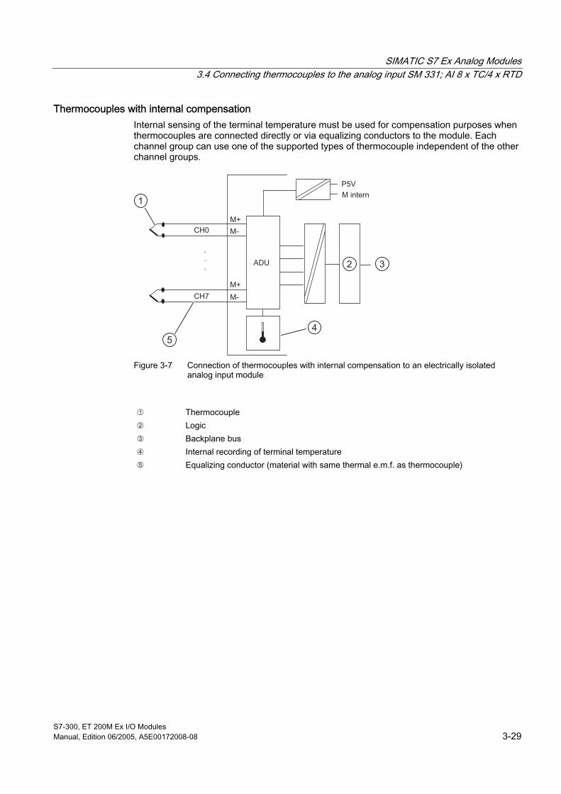
SIMATIC S7 Ex Analog Modules 3.4 Connecting thermocouples to the analog input SM 331; AI 8 x TC/4 x RTD
S7-300, ET 200M Ex I/O Modules Manual, Edition 06/2005, A5E00172008-08 3-29
Thermocouples with internal compensation Internal sensing of the terminal temperature must be used for compensation purposes when thermocouples are connected directly or via equalizing conductors to the module. Each channel group can use one of the supported types of thermocouple independent of the other channel groups.
1
2 3
45
M+
M-
M+
M-
ADU
M intern
CH0
CH7
.
.
.
P5V
Figure 3-7 Connection of thermocouples with internal compensation to an electrically isolated
analog input module
➀ Thermocouple ➁ Logic ➂ Backplane bus ➃ Internal recording of terminal temperature ➄ Equalizing conductor (material with same thermal e.m.f. as thermocouple)

SIMATIC S7 Ex Analog Modules 3.5 Connection of resistance thermometers (e.g. Pt100) and resistance sensors
S7-300, ET 200M Ex I/O Modules 3-30 Manual, Edition 06/2005, A5E00172008-08
3.5 3.5 Connection of resistance thermometers (e.g. Pt100) and resistance sensors
Measurement The resistance thermometers / resistant sensors are measured by means of a 4-wire connection terminal. The resistance thermometers/resistance sensors are fed a constant current via terminals IC + and IC. The voltage produced at the resistance thermometer/resistant sensors is measured via terminals M+ and M-. In this way, a higher degree of accuracy of the measured results at the 4-wire connection terminal is achieved.
Lines for analog signals Shielded lines twisted in pairs are used for analog signals. So as to reduce interference influence.
Use a twisted-pair wire for the constant current line IC+ and the sensing line M+ in the 4-wire connection of thermal resistors and a second twisted pair for IC+ / M+. You will achieve a further improvement if you also twist these two twisted-pair wires with each other (star-quad).
Furthermore, the information provided in the respective section on differences in potential UCM and UISO between the individual circuits still remains valid.
1 2
M+
M-
ADU
IC+
IC-
IC
P5V
M+
M-
IC+
IC-
IC
CH0
CH6
CH7
CH1
.
.
.
M intern
Figure 3-8 Connection of resistance thermometers to isolated analog input module SM 331; AI 8 x
TC/4 x RTD
➀ Logic ➁ Backplane bus
For the 2-wire, 3-wire connection, you must connect corresponding jumpers in the module between M+ and IC + or M- and IC - . However, loss of precision in the measurement should be expected, as voltage drops at the relevant supply lines cannot be recorded.

SIMATIC S7 Ex Analog Modules 3.6 Using thermocouples
S7-300, ET 200M Ex I/O Modules Manual, Edition 06/2005, A5E00172008-08 3-31
3.6 3.6 Using thermocouples
Installation of thermocouples A thermocouple consists of
• the actual thermocouple (measuring sensor) and
• the necessary installation and connection parts.
The thermocouple consists of two wires which are made of different metals or metal alloys and whose ends are soldered or welded together. The different material compositions produce different types of thermocouples, e.g. K, J,N. Irrespective of the type of thermocouple, the measuring principle is the same for all.
1
2
3
4
5
6
7 ° C
Figure 3-9 Measuring circuit with thermocouple
➀ Measuring junction ➁ Thermocouple with positive and negative limbs ➂ Connection point ➃ Equalizing conductor (material with same thermal e.m.f. as thermocouple) ➄ Reference junction ➅ Copper conductor ➆ Thermal e.m.f. acquisition point

SIMATIC S7 Ex Analog Modules 3.6 Using thermocouples
S7-300, ET 200M Ex I/O Modules 3-32 Manual, Edition 06/2005, A5E00172008-08
Operating principle of thermocouples If the measuring junction is subjected to a different temperature than at the free ends of the thermocouple (connection point), a voltage, i.e. the thermal e.m.f., is produced between the free ends.
The value of the thermal e.m.f. depends on the difference between the temperature at the measuring junction and the temperature at the free ends as well as on the type of material combination used for the thermocouple. Since a temperature difference is always recorded with a thermocouple, the free ends must be kept at a known temperature at a reference junction in order to determine the temperature of the measuring junction.
Extension to a reference junction Thermocouples can be extended from their connection point by equalizing conductors up to a point with known temperature (reference junction).
The material of the equalizing conductors has the same thermal e.m.f. as the wires of the thermocouple. The conductors leading from the reference junction up to the analog module are made of copper.
Using thermostatically controlled terminal boxes It is possible to use temperature-compensated terminal boxes. Use boxes with reference junction temperatures of 0 °C or 50 °C when using thermostatically controlled terminal boxes.
Compensation of thermocouples External or internal compensation can be adopted depending on where (locally) you require the reference junction.
In the case of external compensation, the temperature of the reference junction for thermocouples is taken into consideration by means of a compensation box or thermal resistor.
In the case of internal compensation, the internal terminal temperature of the module is used for the comparison.
External compensation The temperature of the reference junction can be compensated by means of a compensating circuit, e.g. by a compensation box.
The compensation box contains a bridge circuit which is calibrated for a certain reference junction temperature (compensating temperature). The terminal connections for the ends of the equalizing conductor of the thermocouple form the reference junction.
If the actual reference temperature deviates from the compensating temperature the temperature-dependent bridge resistance will change. A positive or negative compensation voltage is produced which is added to the thermal e.m.f.
Compensation boxes with a reference junction temperature of 0 °C must be used for the purpose of compensating the analog input modules.
A further external compensation option is to record the reference junction temperature with a thermal resistor in the climatic range (e.g. Pt 100).

SIMATIC S7 Ex Analog Modules 3.6 Using thermocouples
S7-300, ET 200M Ex I/O Modules Manual, Edition 06/2005, A5E00172008-08 3-33
The following conditions must be observed:
• External compensation by means of a compensation box can only be carried out for one specific type of thermocouple. This means all channels of this module which operate with external compensation must be parameterized for the same type of thermocouple.
Module diagnostic signals "incorrect parameters in module" and "reference channel error" for the corresponding channels (0..5) in the case of incorrect parameterization.
• The parameters of a channel group apply to both channels of this channel group (e.g. type of thermocouple, integration time, etc.)
Internal compensation For the purposes of internal compensation, you can form the reference junction at the terminals of the analog input module. In this case, you must route the compensating conductors to the analog module. The internal temperature sensor senses the terminal temperature of the module. The thermocouples (also different types) connected to the module are compensated with this temperature.
Note For the analog input module SM 331; SI 8 x TC/4 x RTD, the compensation box is connected to terminals 18 and 19. The thermal resistor is connected to terminals 16, 17, 18 and 19 in order to register the reference junction temperature.

SIMATIC S7 Ex Analog Modules 3.7 Connecting voltage sensors
S7-300, ET 200M Ex I/O Modules 3-34 Manual, Edition 06/2005, A5E00172008-08
3.7 3.7 Connecting voltage sensors
Connecting voltage sensors to isolated analog input module SM 331; AI 8 x TC/4 x RTD
1 2
+
-U
M+
M-
M+
M-
ADU
P5V
+
-
CH0
CH7
.
.
.
M intern
U
Figure 3-10 Connecting voltage sensors to isolated analog input module SM 331; AI 8 x TC/4 x RTD
➀ Logic ➁ Backplane bus
Furthermore, the information provided in the chapter "Connecting Transducers to Analog Inputs" on differences in potential UCM and UISO between the individual circuits still remains valid.

SIMATIC S7 Ex Analog Modules 3.8 Connecting current sensors or measuring transducers to the analog inputs SM 331; AI 4 x 0/4...20 mA
S7-300, ET 200M Ex I/O Modules Manual, Edition 06/2005, A5E00172008-08 3-35
3.8 3.8 Connecting current sensors or measuring transducers to the analog inputs SM 331; AI 4 x 0/4...20 mA
Connecting current sensors as 2-wire and 4-wire transducers The following description refers to the operation of transducers together with the analog input module SM 331; AI 4 x 0/4...20 mA.
The 2-wire transducer is supplied short-circuit-proof via the isolated measuring transducer supply L0+ ... L3+ of the corresponding analog channel. The 2-wire transducer then converts the supplied measured variable into a current between 4...20 mA.
4-wire transducers feature a separate supply voltage connection which must be powered by an external power supply unit.
Furthermore, the information provided in the chapter "Connecting Transducers to Analog Inputs" on differences in potential UCM and UISO between the individual circuits still remains valid.
1
2 3
4
RS
MU
A
D
L0+
M0-
M0+
I
4...20 mA
L+
UM
ϑ, Ρ, υ...
M
50Ω
Figure 3-11 Connecting 2-wire transducers to the analog inputs SM 331; AI 4 x 0/4... 20 mA and
AI 2 x 0/4 20 mA HART
➀ Transducer supply ➁ Logic ➂ Backplane bus ➃ e.g. pressure, temperature

SIMATIC S7 Ex Analog Modules 3.9 Connecting Loads/Actuators to the Analog Output Module SM 332; AO 4 x 0/4...20 mA
S7-300, ET 200M Ex I/O Modules 3-36 Manual, Edition 06/2005, A5E00172008-08
1
2 3
4
RSA
D
L0+
M0-
M0+
UMMU
0/4...20 mA
Uv -
Uv +
L+M
ϑ, Ρ, υ...
50Ω
Figure 3-12 Connecting 4-wire transducers with external supply to the analog input module SM 331;
AI 4 x 0/4... 20 mA and AI 2 x 0/4 20 mA HART
➀ Transducer supply ➁ Logic ➂ Backplane bus ➃ e.g. pressure, temperature
3.9 3.9 Connecting Loads/Actuators to the Analog Output Module SM 332; AO 4 x 0/4...20 mA
Introduction The analog output modules can be used to supply loads/actuators with current.
Lines for analog signals Shielded lines twisted in pairs are used for analog signals. So as to reduce interference influence.
You should ground the shield of the analog lines at both ends. If there are differences in the potential between the line ends, an equipotential bonding current can flow across the shield and cause interference in the analog signals. In this case, the shield should only be grounded at one end of the line.

SIMATIC S7 Ex Analog Modules 3.9 Connecting Loads/Actuators to the Analog Output Module SM 332; AO 4 x 0/4...20 mA
S7-300, ET 200M Ex I/O Modules Manual, Edition 06/2005, A5E00172008-08 3-37
Isolated analog output modules There is no metallic connection between each of the reference points M0- ... M3- of the analog circuits and the M terminal of the CPU in the isolated analog output modules.
Isolated analog input modules are used when there could be a difference in the potential UISO between the reference point of the analog circuit M3- and the M terminal of the CPU. Take particular care to ensure that the difference in potential UISO does not exceed the permissible value. In cases where it is possible that the permissible value is exceeded, provide a connection between the terminal M0- ... M3- and the M terminal of the CPU.
Connecting loads to a current output You must connect loads to an output current at, e.g., QI0 and the reference point M0- of the analog circuit.
1 2
3
M
L+
DAU RL
QI0
M0-
ML+M
CPUUISO
0/4...20 mA
I
Figure 3-13 Connection of loads to a current output of the isolated analog output module
SM 332; AO 4 x 0/4...20 mA
➀ Backplane bus ➁ Logic ➂ Ground bus

SIMATIC S7 Ex Analog Modules 3.10 Basic Requirements for the Use of Analog Modules
S7-300, ET 200M Ex I/O Modules 3-38 Manual, Edition 06/2005, A5E00172008-08
3.10 3.10 Basic Requirements for the Use of Analog Modules
3.10.1 Conversion and Cycle Time of Analog Input Channels
Conversion time The conversion time is made up of the basic conversion time and additional processing times for wire break monitoring.
The basic conversion time depends directly on the conversion method (integral action, successive approximation or sigma-delta method) of the analog input channel. In the case of integral action conversion, the integration time is included directly in the conversion time. The integration time has a direct influence on the resolution. The integration times of the individual analog modules are specified in the respective chapter. The settings are carried out in STEP 7.
Cycle time Analog/digital conversion and transfer of the digitized measured values to the memory or on the backplane bus of the S7-300 take place sequentially, i.e. the analog input channels are converted one after the other. The cycle time, i.e. the time required until an analog input value has been converted again, is the sum of the conversion times of all activated analog input channels of the analog input module. The conversion time is based on channel groups when the analog input channels are combined in channel groups by means of parameterization. In the analog input modules SM 331; AI 8 x TC/4 x RTD, 2 analog input channels are combined to form one channel group. You must therefore subdivide the cycle time into steps of 2. Unused analog input channels should be deactivated by means of parameterization in STEP 7 in order to reduce the cycle time.
The diagram shows an overview of how the cycle time is made up for an n-channel analog input module.
Conversion time channel 1
Conversion time channel 2
Cycle time
Conversion time channel n
Figure 3-14 Cycle time of an analog input module

SIMATIC S7 Ex Analog Modules 3.10 Basic Requirements for the Use of Analog Modules
S7-300, ET 200M Ex I/O Modules Manual, Edition 06/2005, A5E00172008-08 3-39
3.10.2 Conversion, Cycle, Transient Recovery and Response Times of Analog Output Channels
Conversion time The conversion time of analog output channels includes the transfer of digitized output values and digital/analog conversion.
Cycle time In the SM 332; AO 4 x 0/4...20 mA, conversion of the analog output channels takes place in parallel, i.e. on receipt of the data, all four analog output channels are converted simultaneously.
The cycle time, i.e. the time required until an analog output value is re-converted, is constant and equals the conversion time.
Transient recovery time The transient recovery time (t2 to t3), i.e. the time from applying the converted value up to achieving the specified value at the analog output is dependent on load. A differentiation is made between resistive, capacitive and inductive load.
Response time In the most unfavorable case, the response time (t1 to t3), i.e. the time from receiving the digital output values in the module up to obtaining the specified value at the analog output is the sum of the cycle time and transient recovery time. The most unfavorable case is when channel conversion begins just before transfer of a new output value.
The digitized output values are connected simultaneously to all output channels.
tA
tZ
tE
t1
t2 t
3 Figure 3-15 Response time of the analog input channels
tA Response time tZ Cycle time tE Transient recovery time t1 New digitized output value applied t2 Output value accepted and converted t3 Specified output value obtained

SIMATIC S7 Ex Analog Modules 3.10 Basic Requirements for the Use of Analog Modules
S7-300, ET 200M Ex I/O Modules 3-40 Manual, Edition 06/2005, A5E00172008-08
3.10.3 Parameters of Analog Modules
Parameterization You set the parameters of the analog modules with STEP 7 . These settings must then be transferred in STOP mode to the CPU. During the status change from STOP→ RUN, the CPU then transfers the parameters to the relevant analog modules.
You can also change some parameters in the user program with SFC 55. You can find out which parameters can be changed in this way in Appendix A of the S7-300, Modules Reference Manual. Using SFC 56 and 57 you can transfer the parameters set using STEP 7 in RUN of the CPU to the analog module.
The parameters are subdivided as follows for the 2 parameterization alternatives:
• static parameters and
• dynamic parameters
The table below shows the characteristics of static and dynamic parameters.
Parameter Can be set with CPU operating status static Programming Devices STOP
Programming Devices STOP dynamic SFC 55 in user program RUN
Configurable characteristics The characteristics of the analog modules can be parameterized in STEP 7 with the following parameter blocks:
• for input channels
– Basic settings (enables)
– Limits (triggers for hardware interrupt)
– Diagnostics
– Measurement
• for output channels
– Basic settings
– Diagnostics
– Default values
– Output

SIMATIC S7 Ex Analog Modules 3.10 Basic Requirements for the Use of Analog Modules
S7-300, ET 200M Ex I/O Modules Manual, Edition 06/2005, A5E00172008-08 3-41
Parameters of analog input modules The tables provide an overview of the parameters for analog input modules and show what parameters
• are static or dynamic and
• can be set for the modules as a whole or for a channel group or a channel.
Table 3-21 Parameters of the Analog Input Module SM 331; AI 8 x TC/4 x RTD
Parameter Range of values Default setting Type of parameter Effective range Basic settings Enable
• Diagnostic interrupt
yes/no no
• Hardware interrupt on exceeding limit
yes/no no
• Hardware interrupt at end of cycle
yes/no no
dynamic module
Limit • Upper limit from 32511 to -35512 32767 • Lower limit from -32512 to 32511 -32768
dynamic channel
Diagnostics • Group
diagnostics yes/no no
• with wire break monitoring
yes/no no
static Channel group
Measurement • Interference
frequency suppression
400 Hz; 60 Hz; 50 Hz; 10 Hz
50 Hz dynamic Channel group

SIMATIC S7 Ex Analog Modules 3.10 Basic Requirements for the Use of Analog Modules
S7-300, ET 200M Ex I/O Modules 3-42 Manual, Edition 06/2005, A5E00172008-08
Parameter Range of values Default setting Type of parameter Effective range • Measurement
type - deactivated - Voltage - Resistance 4-wire connection - Thermal resistance (RTD) with linearization 4-wire configuration - Thermocouple with linearization and compensation at 0 °C - Thermocouple with linearization and compensation at 50 °C- Thermocouple with linearization and internal compensation - Thermocouple with linearization and external compensation 1
Voltage dynamic Channel group
• Measuring range
±1V dynamic Channel group
1 The following types of compensation are possible with this measurement mode: • Use of a compensation box
The compensation box must correspond to the connected type of thermocouple.
All thermocouples must be of the same type. • Use of a thermal resistor for compensation (e.g. Pt100) The absolute terminal temperature is determined for compensation with a Pt100 resistor in the climatic range. In this case, the thermocouples to be compensated can be of different types.

SIMATIC S7 Ex Analog Modules 3.10 Basic Requirements for the Use of Analog Modules
S7-300, ET 200M Ex I/O Modules Manual, Edition 06/2005, A5E00172008-08 3-43
Table 3-22 Parameters of the analog input module SM 331; AI 4 x 0/4...20 mA
Parameter Range of values Default setting Type of parameter Effective range Basic settings Enable
• Diagnostic interrupt
yes/no no
• Hardware interrupt on exceeding limit
yes/no no
• Hardware interrupt at end of cycle
yes/no no
dynamic module
Limit • Upper limit from 32511 to -32512 32767 • Lower limit from -32512 to 32511 -32768
dynamic channel
Diagnostics • Group
diagnostics yes/no no
• with wire break monitoring
yes/no no
static Channel group
Measurement • Interference
frequency suppression
400 Hz; 60 Hz; 50 Hz; 10 Hz
50 Hz dynamic Channel group
• Measurement mode
4DMU current (4-wire transducer) 2DMU current (2-wire transducer)
4-wire measuring transducer
dynamic Channel group
• Measuring range
0...20 mA, 4...20 mA
4...20 mA dynamic Channel group
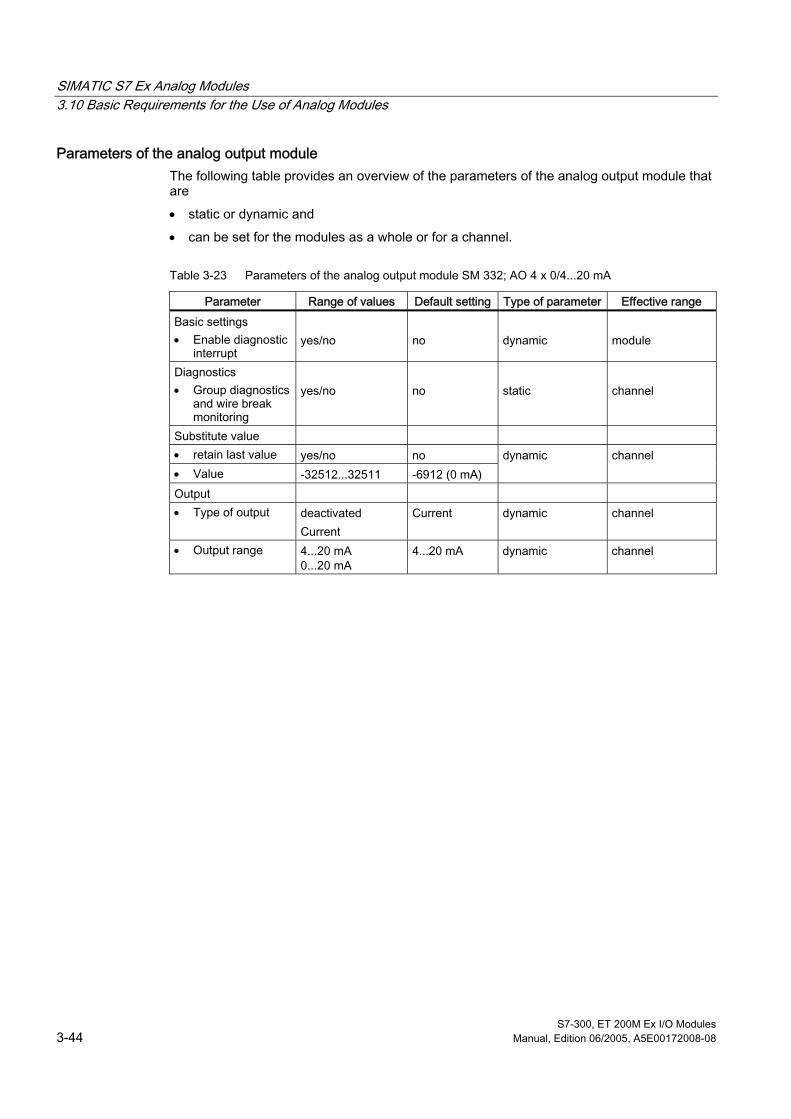
SIMATIC S7 Ex Analog Modules 3.10 Basic Requirements for the Use of Analog Modules
S7-300, ET 200M Ex I/O Modules 3-44 Manual, Edition 06/2005, A5E00172008-08
Parameters of the analog output module The following table provides an overview of the parameters of the analog output module that are
• static or dynamic and
• can be set for the modules as a whole or for a channel.
Table 3-23 Parameters of the analog output module SM 332; AO 4 x 0/4...20 mA
Parameter Range of values Default setting Type of parameter Effective range Basic settings • Enable diagnostic
interrupt
yes/no
no
dynamic
module
Diagnostics • Group diagnostics
and wire break monitoring
yes/no
no
static
channel
Substitute value • retain last value yes/no no • Value -32512...32511 -6912 (0 mA)
dynamic channel
Output • Type of output deactivated
Current Current dynamic channel
• Output range 4...20 mA 0...20 mA
4...20 mA dynamic channel

SIMATIC S7 Ex Analog Modules 3.10 Basic Requirements for the Use of Analog Modules
S7-300, ET 200M Ex I/O Modules Manual, Edition 06/2005, A5E00172008-08 3-45
3.10.4 Diagnostics of the Analog Modules
Definition With the aid of the diagnostics function you can determine whether analog processing is faulty or free of faults and which faults have occurred. On detecting a fault, the analog modules output the signal value "7FFFH" irrespective of the parameterization.
Parameterizing diagnostics Diagnostic mode is parameterized with STEP 7.
Diagnostic evaluation With regard to diagnostic evaluation, differentiation is made between configurable and non-configurable diagnostic messages. In the case of configurable diagnostic messages, evaluation only takes place when diagnostics has been enabled by means of parameterization ("diagnostic enable" parameter). The non-parameterizable diagnostic messages are always evaluated irrespective of the diagnostic enable.
Diagnostic messages trigger following actions:
• SF LED on analog module lights,
• if applicable channel fault LED,
• Transfer of diagnostic message to CPU,
• Diagnostic interrupt triggered (only if diagnostic interrupt has been enabled in the parameterization).

SIMATIC S7 Ex Analog Modules 3.10 Basic Requirements for the Use of Analog Modules
S7-300, ET 200M Ex I/O Modules 3-46 Manual, Edition 06/2005, A5E00172008-08
Diagnostics of the analog input modules The table below provides an overview of the parameterizable diagnostic messages of the analog input modules. The enable is set in the "diagnostics" parameter block. The diagnostic information refers to either the individual channels or the entire module.
Table 3-24 Diagnostic messages of the analog input modules SM 331; AI 8 x TC/4 x RTD, AI 4 x 0 / 4...20 mA and AI 2 x 0/4...20 mA HART
Diagnostic message Effective range of diagnostics
Configurable
Wire break 1 yes
Measuring range underflow
Measuring range overflow
Reference channel fault 2
yes, joint
for all 3 faults
Incorrect parameters in module
channel
no Incorrect parameters in module Module not parameterized external auxiliary voltage missing 3 internal auxiliary voltage missing 3 Fuse blown 3 Time watchdog tripped EPROM error 4 RAM error 4 CPU error 4 ADU error 4 Hardware interrupt lost
module
no
1 If wire break diagnostics is enabled, the modules AI 4 x 0 / 4...20 mA and AI 2 x 0/4...20 mA output the wire break message for the connected 2-wire transducer (4...20 mA) if the input current drops below a value of Iv3.6 mA (wire break limits in accordance with NAMUR). The wire break message is only deactivated (hysteresis), when the input current rises above 3.8 mA again. In the case of the module AI 8 x TC/4 x RTD the line is checked by connecting a test current if wire break diagnostics is enabled. 2 Only for thermocouples with external compensation and compensation fault. 3 Only for AI 4 x 0 / 4...20 mA and AI 2 x 0/4...20 mA HART with 24 volt supply from L+. 4 The tests are conducted during start-up and on-line.

SIMATIC S7 Ex Analog Modules 3.10 Basic Requirements for the Use of Analog Modules
S7-300, ET 200M Ex I/O Modules Manual, Edition 06/2005, A5E00172008-08 3-47
Faults and corrective measures Bear in mind that, in order to detect faults that are indicated by means of configurable diagnostic messages, the module must also be parameterized accordingly.
Table 3-25 Diagnostic messages of the analog input modules SM 331; AI 8 x TC/4 x RTD, AI 4 x 0 / 4...20 mA and AI 2 x 0/4...20 mA HART - their possible causes of fault and corrective measures
Diagnostic message Possible fault causes Corrective measures Break in the line between the module and sensor
Connect line Wire break
Channel not connected (open) Deactivate channel group ("Measurement mode" parameter)
Measuring range underflow Input value below underflow range, fault possibly caused by:
• on AI 8 x TC/4 x RTD • incorrect type of thermocouple • Sensor connected with
reversed polarity - incorrect measuring range selected
• Check type of thermocouple
• Check connection terminals
• Parameterize different measuring range
• on AI 4 x 0 / 4...20 mA • Module does not signal measuring range underflow
• Sensor connected with reverse polarity; (a digitized value is output for 0 mA)
Measuring range overflow Input value exceeds overflow range
Parameterize different measuring range
Measuring channel has different type of sensor parameterized as reference channel
Parameterize different type of sensor
Reference channel fault
Fault in reference channel (e.g. wire break) values of all measuring channels set to 7FFFH
Eliminate fault in reference channel
Incorrect parameters in module Module supplied with invalid parameters
Check parameterization of module and re-load valid parameters
Module not parameterized Module not supplied with parameters
Include module in parameterization
external auxiliary voltage missing No module supply voltage L+ Provide L+ supply No module supply voltage L+ Provide L+ supply no internal auxiliary voltage module-internal fuse defective Replace module
Fuse blown module-internal fuse defective Replace module
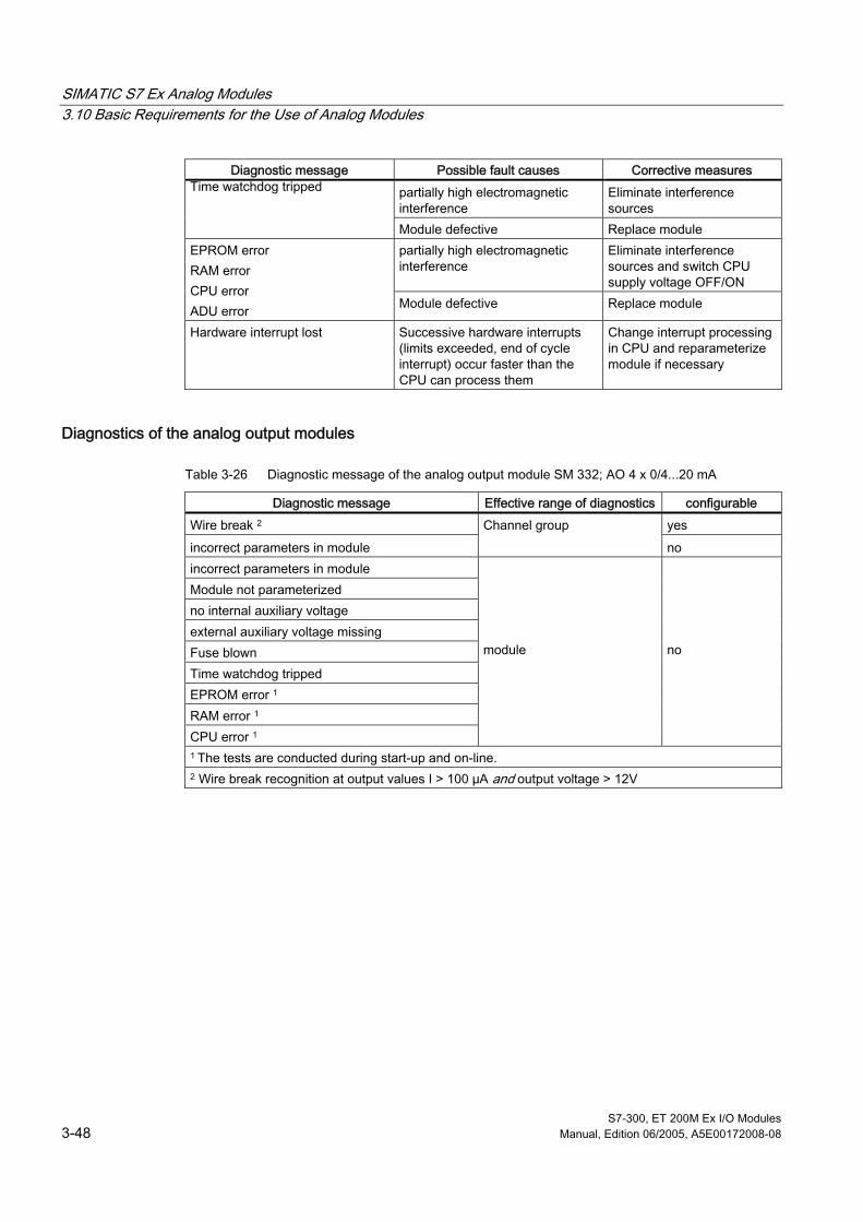
SIMATIC S7 Ex Analog Modules 3.10 Basic Requirements for the Use of Analog Modules
S7-300, ET 200M Ex I/O Modules 3-48 Manual, Edition 06/2005, A5E00172008-08
Diagnostic message Possible fault causes Corrective measures partially high electromagnetic interference
Eliminate interference sources
Time watchdog tripped
Module defective Replace module partially high electromagnetic interference
Eliminate interference sources and switch CPU supply voltage OFF/ON
EPROM error RAM error CPU error ADU error Module defective Replace module
Hardware interrupt lost Successive hardware interrupts (limits exceeded, end of cycle interrupt) occur faster than the CPU can process them
Change interrupt processing in CPU and reparameterize module if necessary
Diagnostics of the analog output modules
Table 3-26 Diagnostic message of the analog output module SM 332; AO 4 x 0/4...20 mA
Diagnostic message Effective range of diagnostics configurable Wire break 2 yes
incorrect parameters in module
Channel group
no incorrect parameters in module Module not parameterized no internal auxiliary voltage external auxiliary voltage missing Fuse blown Time watchdog tripped EPROM error 1 RAM error 1 CPU error 1
module
no
1 The tests are conducted during start-up and on-line. 2 Wire break recognition at output values I > 100 µA and output voltage > 12V

SIMATIC S7 Ex Analog Modules 3.10 Basic Requirements for the Use of Analog Modules
S7-300, ET 200M Ex I/O Modules Manual, Edition 06/2005, A5E00172008-08 3-49
Faults and corrective measures Bear in mind that, in order to detect faults that are indicated by means of configurable diagnostic messages, the module must also be parameterized accordingly.
Table 3-27 Diagnostic messages of analog output module SM 332; AO 4x0/4...20 mA and their possible causes and corrective measures
Diagnostic message possible fault causes Corrective measures
Break in line between module and actuator
Connect line
Voltage at load resistor > 12V Lower load resistance to ≤500 Ω
Wire break
Channel not connected (open) Deactivate channel ("Measurement mode" parameter)
incorrect parameters in module Module supplied with invalid parameters
Check parameterization of module and re-load valid parameters
Module not parameterized Module not supplied with parameters
Include module in parameterization
external auxiliary voltage missing
No module supply voltage L+ Provide L+ supply
No module supply voltage L+ Provide L+ supply no internal auxiliary voltage module-internal fuse defective Replace module
Fuse blown module-internal fuse defective Replace module partially high electromagnetic interference
Eliminate interference sources Time watchdog tripped
Module defective Replace module partially high electromagnetic interference
Eliminate interference sources and switch CPU supply voltage OFF/ON
EPROM error CPU error RAM error
Module defective Replace module
Reading out diagnostic messages You can read out the detailed diagnostic messages in STEP 7 after setting diagnostics for the analog modules.
See also Parameters of Analog Modules (Page 3-40)

SIMATIC S7 Ex Analog Modules 3.10 Basic Requirements for the Use of Analog Modules
S7-300, ET 200M Ex I/O Modules 3-50 Manual, Edition 06/2005, A5E00172008-08
3.10.5 Interrupts of Analog Modules
Types of interrupts In principle, a differentiation is made between the following interrupts:
• Diagnostic interrupt
• Hardware interrupt
Parameterizing interrupts The interrupt is parameterized with STEP 7.
Default setting The interrupts are inhibited by way of default.
Diagnostic interrupt If enabled, the module triggers a diagnostic interrupt when a fault comes or goes (e.g. wire break or short to M). Diagnostic functions inhibited by parameterization cannot trigger an interrupt. The CPU interrupts processing of the user program or low-priority classes and processes the diagnostic interrupt module (OB82).
Hardware interrupt The range is defined by parameterization of an upper and a lower limit. If the process signal (e.g. temperature of an analog input module) is outside this range, the module triggers a hardware interrupt provided limit interrupt is enabled. You can determine which of the channels has triggered the interrupt from the local data of the OB 40 in the user program.
Active hardware interrupts trigger interrupt processing (OB40) in the CPU, consequently the CPU interrupts processing of the user program or low-priority classes. If there are no higher priority classes pending processing, the stored interrupts (of all modules) are processed one after the other corresponding to the order in which they occurred.
Hardware interrupt lost If an event occurred in one channel (overrange/underrange of limit), this event is stored and a hardware interrupt is triggered. If a further event occurs on this channel before the hardware interrupt has been acknowledged by the CPU (OB 40 run) this event will be lost. A diagnostic interrupt "hardware interrupt lost" is triggered in this case. The diagnostic interrupt enable must be active for this purpose.
Further events on this channel are then no longer registered until interrupt processing is completed for this channel.

SIMATIC S7 Ex Analog Modules 3.10 Basic Requirements for the Use of Analog Modules
S7-300, ET 200M Ex I/O Modules Manual, Edition 06/2005, A5E00172008-08 3-51
3.10.6 Characteristics of Analog Modules
Influence of supply voltage and operating status The input and output values of the analog modules are dependent on the supply voltage of the analog module and on the operating status of the CPU.
Table 3-28 Dependencies of analog input/output values on the CPU operating status and the supply voltage L+
CPU operating status
Supply voltage L+ at analog
module
Parameters of analog input modules
Output value of the analog output module
Process value CPU value L+ applied
7FFFH up to first conversion after switching on or after module parameterization has been completed
Up to first conversion ... • after switch-on has been
completed if signal of 0 mA is output.
• after parameterization has been completed, previous value is output.
POWER ON
RUN
No L+ Overflow value 1 0 mA Process value L+ applied 7FFFH up to first conversion after switching on or after module parameterization has been completed
Default/last value at 0...20 mA: 0 mA default at 4...20 mA: 4 mA default
POWER ON
STOP
No L+ Overflow value 1 0 mA L+ applied - 0 mA POWER
OFF -
No L+ - 0 mA 1 only applies to SM 331; AI 8xT C/4 x RTD as no L+ supply voltage is required.
Failure of the L+ supply voltage for the analog modules is always indicated by the group fault LED on the module and additionally entered in diagnostics.
Triggering of a diagnostic interrupt is dependent on the parameterization.

SIMATIC S7 Ex Analog Modules 3.10 Basic Requirements for the Use of Analog Modules
S7-300, ET 200M Ex I/O Modules 3-52 Manual, Edition 06/2005, A5E00172008-08
Table 3-29 Characteristics of analog modules dependent on the position of analog input value in value range
Process value in Input value SF LED Diagnostics Interrupt Channel fault LED
Rated range Process value - - - - Overrange/ underrange Process value - - - - Overflow 7FFFH lit lit Underflow 8000H lit lit Wire break 7FFFH lit 1
Entry made 1 Diagnostic interrupt 1
lit 1 outside parameterized limit
Process value - - Hardware interrupt 1, 2
-
1 depending on parameterization 2 A channel diagnostic error prevents the limit hardware interrupt. Example: An enabled wire break diagnostics renders limits below the wire break threshold ineffective.
Influence of value range for output The characteristics of the output modules depend on what part of the value range the output values are in.
Table 3-30 Characteristics of analog modules dependent on position of analog output value in value range
Output value in Output value SF LED Diagnostics Interrupt Channel fault LED
Rated range CPU value - - - - Overrange/ underrange CPU value - - - - Overflow 0 mA - - - - Wire break CPU value lit 1 Entry
made 1 Entry
made 1 lit 1
1 depending on parameterization
Influence of faults Faults occurring in analog modules with diagnostic capabilities and corresponding parameterization result in diagnostic entry and diagnostic interrupt. Refer to the respective chapter for a list of faults.
The SF LED and, if applicable, the channel fault LED light on the analog module.
Faults which cannot be parameterized in diagnostics (e.g. fuse blown) result in an entry being made in the diagnostic range and the fault LED lighting irrespective of the CPU operating status.
See also Diagnostics of the Analog Modules (Page 3-45)
Parameters of Analog Modules (Page 3-40)

SIMATIC S7 Ex Analog Modules 3.11 Analog input module SM 331; AI 8 x TC/4 x RTD (6ES7331-7SF00-0AB0)
S7-300, ET 200M Ex I/O Modules Manual, Edition 06/2005, A5E00172008-08 3-53
3.11 3.11 Analog input module SM 331; AI 8 x TC/4 x RTD (6ES7331-7SF00-0AB0)
Order Number 6ES7331-7SF00-0AB0
Features The analog input module SM 331, AI 8 x TC/4 x RTD is characterized by the following features:
• 8 inputs in 4 channel groups
• Measured value resolution; adjustable per channel group (depending on set interference frequency rejection)
– 9 Bit + sign (integration time 2.5 ms) ≙ 400 Hz
– 12 Bit + sign (integration time 162/3 / 20 ms) ≙ 60/50 Hz
– 15 Bit + sign (integration time 100 ms) ≙ 10 Hz
• Measurement mode selectable per channel group:
– Voltage
– Resistance
– Temperature
• arbitrary measuring range selection per channel group
• configurable diagnostics
• configurable diagnostic interrupt
• 2 channels with limit monitoring
• configurable limit interrupt
• isolated with respect to CPU
• Common mode < 60 V between the channels
Resolution The resolution of a measured value depends directly on the selected integration time, i.e. the longer the integration time for an analog input channel, the more accurate the resolution of the measured value.

SIMATIC S7 Ex Analog Modules 3.11 Analog input module SM 331; AI 8 x TC/4 x RTD (6ES7331-7SF00-0AB0)
S7-300, ET 200M Ex I/O Modules 3-54 Manual, Edition 06/2005, A5E00172008-08
Terminal diagram Module view and block diagram of SM 331; AI 8 x TC/4 x RTD
M3*
M0+
M0*
M1+
ADU
SF
CH0
M0+
CH0M0*
IC0 +
CH1M1* IC0*
M2+
CH2
M1+
CH2M2 * M1*
M3 +
CH3
IC1 +
IC1*
M4 +
M4*
M5 +
CH4
M2+
CH4M2 *
IC2 +
CH5M5* IC2*
M6 +
CH6
M3 +
CH6M6 * M3*
M7 +
CH7
IC3 +
M7* IC3*
X 23 4
SF
F0
F1
1
2
3
4
5
6
7
8
9
10
11
12
13
14
15
16
17
18
19
20
F2
F3
F4
F5
F6
F7
[Exx ib] IIC
SM 331AI 8xTC / 4xRTD
x
F (0...7) [TC], F (0,2,4,6) [RTD]
331-7SF00-0AB0
F (0...7)
5V internal
M internal
Galvanic isolation
SF Group error indicator [red]
channel-specific fault indication [red]
+ input 0/0
- input 0/0
+ input 1/-
- input 1/-
+ input 2/2
- input 2/2
+ input 3/-
- input 3/-
+ input 4/4
- input 4/4
+ input 5/-
- input 5/-
+ input 6/6
- input 6/6
+ input 7/-
- input 7/-
Internal supply
Internal compensation
Thermocouples, voltage measurement
Resistance measurement
Optomulti-plexer
Galvanic isolation
Power source
Logic and backplane bus
interfacing
Figure 3-16 Module view and block diagram of SM 331; AI 8 x TC/4 x RTD
Notes on intrinsically-safe installation You must connect the DM 370 dummy module between the CPU or IM 153 (in a distributed configuration) and the Ex I/O modules whose signal cables lead into the hazardous location. In a distributed configuration with an active backplane bus, you should use the ex dividing panel/ex barrier instead of the dummy module.

SIMATIC S7 Ex Analog Modules 3.11 Analog input module SM 331; AI 8 x TC/4 x RTD (6ES7331-7SF00-0AB0)
S7-300, ET 200M Ex I/O Modules Manual, Edition 06/2005, A5E00172008-08 3-55
Notes on the module No external voltage supply L+ (24 V) is necessary for the analog input module SM 331; AI 8 x TC/4 x RTD.
If thermal resistors (e.g. Pt100) are used for external compensation, connect them to channels 6 and 7.
If a compensation box is used for external compensation, connect it to channel 7.
Parameterization The functions of the analog input module SM 331; AI 8 x TC/4 x RTD are set
• with STEP 7 (see also user manual STEP 7) or
• in the user program with SFCs.
Default settings The analog input module features default settings for integration time, diagnostics, interrupts etc..
These default settings are valid if re-parameterization has not been carried out via STEP 7.
Channel groups In the analog input module SM 331; AI 8 x TC/4 x RTD, 2 analog input channels are combined to form one channel group. Parameters can always only be assigned to one channel group, i.e. parameters which are specified for a channel group are always valid for both channels of this channel group.
Table 3-31 Module view and block diagram of SM 331; AI 8 x TC/4 x RTD
Channel Allocated channel group Channel 0
Channel 1
Channel group 0
Channel 2 Channel 3
Channel group 1
Channel 4 Channel 5
Channel group 2
Channel 6 Channel 7
Channel group 3

SIMATIC S7 Ex Analog Modules 3.11 Analog input module SM 331; AI 8 x TC/4 x RTD (6ES7331-7SF00-0AB0)
S7-300, ET 200M Ex I/O Modules 3-56 Manual, Edition 06/2005, A5E00172008-08
Special feature of resistant measurement Only one channel per channel group is required for the "resistance measurement". The "2nd" channel of the group is used for current injection (IC).
With access to the "1st" channel of the group you obtain the measured value. The "2nd" channel of the group is preset with the overflow value "7FFFH".
During diagnostics, the 1st channel provides the actual status (in compliance with parameterization) and the 2nd channel "free of faults".
Non-connected input channels Activated and non-connected channels of the analog input module SM 331; AI 8 x TC/4 x RTD must be short-circuited. This way you ensure optimum interference immunity for the analog input module. The non-connected channels should also be deactivated in STEP 7 in order to shorten the module cycle time.
Selectable measurement modes The following measurement modes can be set on the analog input module SM 331; AI 8 x TC/4 x RTD. Perform the setting in STEP 7.
• Voltage measurement
• Resistance measurement
• Temperature measurement
Adjustable measuring ranges The measuring ranges, for which you can use the analog input module SM 331; AI 8 x TC/4 x RTD are specified in the following tables. You can set the required measuring ranges in STEP 7.
Wire break monitoring Provided the parameterization is enabled, the analog output module SM 331; AI 8 x TC/4 x RTD carries out a wire break check for all areas. All 4 terminal wires are monitored for wire break in resistance thermometer mode (RTD).
Measuring ranges for voltage measurements
chosen measurement mode
Explanation Measuring range
Voltage The digitalized analog values can be found in chapter "Analog Representation for Voltage Measuring Ranges of Analog Inputs".
± 25 mV ± 50 mV ± 80 mV ± 250 mV ± 500 mV ± 1 V

SIMATIC S7 Ex Analog Modules 3.11 Analog input module SM 331; AI 8 x TC/4 x RTD (6ES7331-7SF00-0AB0)
S7-300, ET 200M Ex I/O Modules Manual, Edition 06/2005, A5E00172008-08 3-57
Measuring ranges for resistance measurement
chosen measurement mode
Explanation Measuring range
Resistance 4-wire connection
The digitalized analog values can be found in chapter "Analog Representation for Resistance Measuring Ranges of Analog Inputs".
150 ohms 300 ohms 600 ohms
Connectable types of thermocouple The linearization of characteristic curves is specified for thermocouples in accordance with DIN IEC 584.
For thermal resistor measurements, linearization of the characteristic curves is based on DIN 43760 and IEC 43760.
Table 3-32 Connectable thermocouples and thermal resistors
Measurement type Explanation Measuring range • Linearization and compensation
at 0 °C • Linearization and compensation
at 50 °C • Linearization and compensation
internal comparison 1 • Linearization and compensation
external comparison 2
Digitized analog values for the specified thermocouples are listed in chapter "Analog Representation for the Temperature Measuring Ranges of Analog Inputs". (one unit corresponds to 0.1 °C)
Type T [Cu-CuNi] Type U [Cu-CuNi] Type E [NiCr-CuNi] Type J [Fe-CuNi] Type L [Fe-CuNi] Type K [NiCr-Ni] Type N [NiCr-SiNiSi] Type R [Pt13Rh-Pt] Type S [Pt10Rh-Pt] Type B [Pt30Rh-Pt6Rh]
Thermal resistance+ Linearization 4-wire connection (temperature measurement)
Digitized analog values for the specified thermocouples are listed in chapter "Analog Representation for the Temperature Measuring Ranges of Analog Inputs".
Pt100, Pt200, Ni 100 standard range Pt100, Pt200, Ni 100 climatic range
1 In the case of internal compensation in the module, all 8 channels are available for temperature measurements also with different times of thermocouples. • The terminal temperature of the module is provided at a short-circuited input.
This does not apply to thermocouple type B, which is not suitable for measurements in the ambient temperature range.
2 The following types of compensation are possible with this measurement mode: • Use of a compensation box The compensation box must correspond to the connected type of thermocouple. Connection to channel 7. • Use of thermal resistors in climatic range (e.g. Pt100) for compensation. The absolute terminal temperature is determined in the climatic range with a thermal resistor (e.g. Pt100) for compensation purposes. In this case, the thermocouples to be compensated can be of different types. Connection to channels 6 and 7.

SIMATIC S7 Ex Analog Modules 3.11 Analog input module SM 331; AI 8 x TC/4 x RTD (6ES7331-7SF00-0AB0)
S7-300, ET 200M Ex I/O Modules 3-58 Manual, Edition 06/2005, A5E00172008-08
Analog input SM 331; AI 8 x TC/4 x RTD Dimensions and Weight Dimensions W x H x D (mm) 40 x 125 x 120 Weight approx. 210 g Module-specific data Number of inputs • with resistance sensor
8 4
Line length, shielded max. 200 m max. 50 m for voltage ranges ≤ 80 mV and thermocouples
KEMA protection (see Appendix)
II 3 (2) G EEX nA [lib] IIC T4
Test number KEMA 01ATEX1061 X FM protection (see Appendix)
Class I, Division 2, Group A, B, C, D T4 Class I, Zone 2, Group IIC T4
Voltages, currents, potentials Bus power supply 5 V DC Galvanic isolation • between the channels and backplane bus yes • between the channels no Permissible difference in potential of signals from hazardous area • between the channels and backplane bus (UISO) 60 V DC
30 V AC • between the channels (UCM) 60 V DC
30 V AC Insulation tested • Channels with respect to backplane bus with 1500 V AC Current input from backplane bus max. 120 mA Module power loss typical 0.6 W Permissible difference in potential of signals from non-hazardous area • between the channels and backplane bus (UISO) 400 V DC
250 V AC • between the channels (UCM) 75 V DC
60 V AC

SIMATIC S7 Ex Analog Modules 3.11 Analog input module SM 331; AI 8 x TC/4 x RTD (6ES7331-7SF00-0AB0)
S7-300, ET 200M Ex I/O Modules Manual, Edition 06/2005, A5E00172008-08 3-59
Analog input SM 331; AI 8 x TC/4 x RTD Safety data (see EU special test certificate KEMA 01ATEX1061 X in Appendix under "Certificates of Conformity") Maximum values per channel for thermocouples and thermal resistors • U0 (no-load output voltage) max. 5.9 V • I0 (short-circuit current) max. 28.8 mA • P0 (load power) max. 41.4 mW • L0 (permissible external inductance) max. 40 mH • C0 (permissible external capacity) max. 43 µF • Um (error voltage) max. 60 V DC
30 V AC • Ta (permissible ambient temperature) max. 60°°C With connection of an active sensor with the following maximum values Ui = ± 1.2V Ii = 20 mA deviating from the above-specified values • L0 (permissible external inductance) max. 15 mH • C0 (permissible external capacity) max. 14.6 µF Analog value formation Measuring principle SIGMA-DELTA Integration time/conversion time/resolution (per channel) • configurable • Integration time in ms
yes 2,5
yes 162/3
yes 20
yes 100
• Basic conversion time = • 3 x integration time + • Transient recover time optomultiplexer in ms
7,5 + 2,5
50 + 2,5
60 + 2,5
300 + 2,5
• additional conversion time for wire break recognition in ms
2,5 2,5 2,5 2,5
• Resolution in bit (incl. overrange) 9+sign 12+sign 12+sign 15+sign • Interference voltage suppression for interference
frequency f1 in Hz 400 60 50 10
Interference suppression, error limits Interference voltage suppression for f = n x (f1 ± 1 %), (f1 = interference frequency) • Common-mode rejection (UISO < 60 V) > 130 dB • Normal-mode rejection (interference peak value < rated
value of input range) > 40 dB
Crosstalk attenuation between inputs (UISO < 60 V) > 70 dB Operational limit (in total temperature range, referred to input range) • ± 25 mV • ± 50 mV • ± 80 mV • ±250 mV/±500 mV/±1V
± 0,09 % ± 0,06 % ± 0,05 % ± 0,04 %

SIMATIC S7 Ex Analog Modules 3.11 Analog input module SM 331; AI 8 x TC/4 x RTD (6ES7331-7SF00-0AB0)
S7-300, ET 200M Ex I/O Modules 3-60 Manual, Edition 06/2005, A5E00172008-08
Analog input SM 331; AI 8 x TC/4 x RTD Basic error limit (operational limit at 25 °C, referred to input range) • ± 25 mV • ± 50 mV • ± 80 mV • ±250 mV/±500 mV/±1V
± 0,018 % ± 0,014 % ± 0,011 % ± 0,008 %
Temperature error (referred to input range) • ± 25 mV • ± 50 mV • ± 80 mV • ±250 mV/±500 mV/±1V
± 0.0019 %/K ± 0.0013 %/K ± 0.0011 %/K ± 0.0010 %/K
Linearity error (referred to input range) ± 0,003 % Repeatability (in steady-state condition at 25 °C, referred to input range)
± 0,003 %
The accuracy of temperature measurement with external compensation with thermal resistors is derived from:
• Error for the analog input of the type of thermocouple used
• Accuracy 1 of the type of thermal resistor used for compensation
• Error 1 of the compensation input The accuracy of temperature measurement with external compensation with compensation box is derived from:
• Error for the analog input of the type of thermocouple used
• Accuracy 1 of the compensation box • Error 1 of the compensation input
The accuracy of temperature measurement with compensation of the external reference junction maintained at 0 °C / 50 °C is derived from:
• Error for the analog input of the type of thermocouple used
• Accuracy 1 of the reference junction temperature
The accuracy of temperature measurement with internal compensation (terminal temperature) results from:
• Error for the analog input of the type of thermocouple used
• Accuracy 1 of the internal reference junction temperature ± 2.5 K (in the range 0 to 60 °C
1 Due to the constant increase in the thermocouple characteristic at higher temperatures, the error in the compensation element is less effective than at temperatures in the vicinity of the compensation temperature. Exception: Thermocouple types J and E (relative linear progression) Due to the little increase in the range from approx. 0 °C to 40 °C, the lack of compensation of the reference junction temperature has only a negligible effect in the case of thermocouple type B. If there is no compensation and the measurement mode "Compensation to 0 °C" is set, the deviation in thermocouple type B during the temperature measurement is between 700°C and 1820°C < 0.5°C 500 °C and 700 °C < 0.7°C. "Internal compensation" should be set if the reference junction temperature closely corresponds to the module temperature. This reduces the error for the temperature range from 500 °C to 1820 °C to < 0.5 °C.

SIMATIC S7 Ex Analog Modules 3.11 Analog input module SM 331; AI 8 x TC/4 x RTD (6ES7331-7SF00-0AB0)
S7-300, ET 200M Ex I/O Modules Manual, Edition 06/2005, A5E00172008-08 3-61
Error limits of analog inputs for thermocouples (at 25 °C ambient temperature and 100 ms integration time) Type Temperature range Basic error 1 Temperature error 2 [°C/K] T -150 °C...+400 °C
-230 °C... -150°C ±0.2K ±1K
± 0,006
U -50 °C...+400 °C 200 °C....-50 °C
±0.2K ±1K
± 0,006
E -100 °C....+1000 °C -200 °C....-100 °C
±0.2K ±1K
± 0,0075
J -150 °C....+1200 °C -210 °C... -150 °C
±0.2K ±0.5K
± 0,02
L -50 °C...+1200 °C -200 °C....-50 °C
±0.2K ±1K
± 0,02
K -100 °C....+1372 °C 220 °C....-100 °C
±0.2K ±1K
± 0,018
N -50 °C...+1300 °C 150 °C....-50 °C
±0.2K ±1K
± 0,025
R +200 °C....+1769 °C -50 °C...+200 °C
±0.3K ±1K
± 0,025
S +100 °C....+1769 °C -50 °C...+100 °C
±0.3K ±1K
± 0,025
B +700 °C....+1820 °C +500 °C....+700 °C +200 °C....+500 °C
±0.3K ±0.5K ±3K
± 0,04
Error limits of analog inputs for thermal resistors
(at 25 °C ambient temperature and 100 ms integration time) Type Temperature range Basic error 1 Temperature error 2 [°C/K] Pt100 climatic -200 °C....+325 °C ± 0.05K ± 0,006 Pt200 climatic -200 °C....+325 °C ± 0.05K ± 0,006 Ni 100 climatic -60 °C....+250 °C ± 0.05K ± 0,003 Pt100 standard -200° C....+850 °C ± 0.2K ± 0,01 Pt200 standard -200 °C....+850 °C ± 0.2K ± 0,01 Ni 100 standard -60 °C....+250 °C ± 0.1K ± 0,003 Error limits of analog inputs for resistance sensors
(at 25 °C ambient temperature and 100 ms integration time) Type Resistance sensor Basic error 3 Temperature error 2 [°C/K] 150 Ω 0.000 Ω .176.383 Ω ± 0,006% ± 0,001 300 Ω 0.000 Ω .352.767 Ω ± 0,006% ± 0,001 600 Ω 0.000 Ω .705.534 Ω ± 0,006% ± 0,001 1 The basic error includes the linearization error of the voltage temperature conversion and the basic error of the analog/digital conversion at Tu = 25°C. 2 The total temperature error = temperature error x max. ambient temperature change DTu as a temperature difference with respect to 25°C . 3 The basic error includes error in % of the measuring range of the analog/digital conversion at Tu = 25°C.

SIMATIC S7 Ex Analog Modules 3.11 Analog input module SM 331; AI 8 x TC/4 x RTD (6ES7331-7SF00-0AB0)
S7-300, ET 200M Ex I/O Modules 3-62 Manual, Edition 06/2005, A5E00172008-08
The operating error for the use of thermocouples / thermal resistors consists of:
• Basic error of the analog input at Tu = 25°C
• Total temperature error
• Errors which occur due to the compensation of the reference junction temperature
• Errors of the thermocouple / thermal resistor used
The operating error for the use of thermal resistors consists of:
• Basic error of the analog input at Tu = 25°C
• Total temperature error
• Error for the sensor used
Interrupts, diagnostics Interrupts • Limit interrupt configurable channels 0 and 2 • Diagnostic interrupt configurable Diagnostic functions configurable • Group fault indication red LED (SF) • Channel fault indication red LED (F) per channel • Diagnostic information readout possible Data for sensor selection Input ranges (rated values) / input resistance • Voltage
± 25 mV ± 50 mV ± 80 mV ± 250 mV ± 500 mV ± 1 V
/10 MΩ /10 MΩ /10 MΩ /10 MΩ /10 MΩ /10 MΩ
• Resistance 150 Ω 300 Ω 600 Ω
/10 MΩ /10 MΩ /10 MΩ
• Thermocouples Type: T, U, E, J, L, K, N, R, S, B
/10 MΩ
• Resistance thermometer Pt100, Pt200, Ni100 /10 MΩ Measuring current for thermal resistors and wire break testing
c. 0.5 mA
Permissible input voltage for voltage input (destruction limit)
max. 35 V permanent; 75 V for max. 1 s (pulse duty factor 1:10)
Signal sensor connection • for voltage measurement possible • for resistance measurement with 4-wire connection
with 3-wire connection 1 with 2-wire connection 1 possible

SIMATIC S7 Ex Analog Modules 3.11 Analog input module SM 331; AI 8 x TC/4 x RTD (6ES7331-7SF00-0AB0)
S7-300, ET 200M Ex I/O Modules Manual, Edition 06/2005, A5E00172008-08 3-63
Interrupts, diagnostics Characteristic linearization configurable • for thermocouples • Type :
T, U, E, J, L, K, N, R, S, B • for thermal resistors • Pt100, Pt200, Ni 100 (standard and
climatic range) Temperature compensation configurable • Internal temperature compensation possible • external temperature compensation with
compensation box possible
• external temperature compensation with thermal resistors (e.g. Pt100)
possible
• Compensation for 0 °C reference junction temperature
possible
• Compensation for 50 °C reference junction temperature
possible
1 without line resistance correction
See also Configuration of an S7-300 with Ex I/O Modules (Page 1-8)
Configuration of an ET 200M with Ex I/O modules (Page 1-11)
Parameters of Analog Modules (Page 3-40)

SIMATIC S7 Ex Analog Modules 3.12 Analog input module SM 331; AI 4 x 0/4...20 mA (6ES7331-7RD00-0AB0)
S7-300, ET 200M Ex I/O Modules 3-64 Manual, Edition 06/2005, A5E00172008-08
3.12 3.12 Analog input module SM 331; AI 4 x 0/4...20 mA (6ES7331-7RD00-0AB0)
Order Number 6ES7331-7RD00-0AB0
Features The analog input module SM 331, AI 4 x 0/4 ... 20 mA is characterized by the following features:
• 4 inputs in 4 channel groups
• Measured value resolution; adjustable per channel group (depending on set interference frequency rejection)
– 10 Bit (integration time 2.5 ms)
– 13 Bit (integration time 162/3 / 20 ms)
– 15 Bit (integration time 100 ms)
• Measurement type can be selected for each channel:
– Current
– Channel deactivated
• arbitrary measuring range selection for each channel
– 0 ... 20 mA
– 4 ... 20 mA
• configurable diagnostics and configurable diagnostic interrupt
• Channel 0 and 2 with limit value monitoring and configurable limit interrupt
• Channels isolated among each other and with respect to CPU and load voltage L+
• The analog inputs are HART-compatible
Resolution The resolution of a measured value depends directly on the selected integration time, i.e. the longer the integration time for an analog input channel, the more accurate the resolution of the measured value.

SIMATIC S7 Ex Analog Modules 3.12 Analog input module SM 331; AI 4 x 0/4...20 mA (6ES7331-7RD00-0AB0)
S7-300, ET 200M Ex I/O Modules Manual, Edition 06/2005, A5E00172008-08 3-65
Terminal diagram of the SM 331; AI 4 x 0/4...20 mA
ADU
SF
CH0
L0+
M0+
M0-
M1+ CH1
M1-
M2-
CH2M2+
CH3
X 23 4
331-7RD00-0AB0
[EEx ib] IICx
F (0..3)
5V internal
M internal
+
-
+
L +
4-w
ire
2-w
ire
+
-
+
4-w
ire
2-w
ire
+
-
+
4-w
ire
2-w
ire
+
-
+
4-w
ire
2-w
ire
M
50 Ω
390 Ω
L +M
L +M
L +M
L +M
50 Ω
50 Ω
50 Ω
M
L +L +
L1+
L2+
M3 +
M3-
L3+
AI 4 x 0 / 4...20 mA
M
SF
F0
F1
1
2
3
4
5
6
7
8
9
10
11
12
13
14
15
16
17
18
19
20
F2
F3
SM 331
SF Group error indicator [red]
F (0...3) channel-specific fault indication [red]
Input 1
Input 0
Input 2
Input 3
Galvanic isolation
Logic and backplane
bus interfacing
2-wire measuring transducer
4-wire measuring transducer
Isolation amplifier
Galvanic isolation
Figure 3-17 Module view and block diagram of the SM 331; AI 4 x 0/4...20 mA
Notes on intrinsically safe installation You must connect the DM 370 dummy module between the CPU or IM 153 (in a distributed configuration) and the Ex I/O modules whose signal cables lead into the hazardous location. In a distributed configuration with an active backplane bus, you should use the ex dividing panel/ex barrier instead of the dummy module.
Power supply for an intrinsically-safe structure In order to maintain the clearances and creepage distances, L+/M must be routed via the line chamber LK393 when operating modules with signal cables that lead to the hazardous location.

SIMATIC S7 Ex Analog Modules 3.12 Analog input module SM 331; AI 4 x 0/4...20 mA (6ES7331-7RD00-0AB0)
S7-300, ET 200M Ex I/O Modules 3-66 Manual, Edition 06/2005, A5E00172008-08
Additional measures The safety data of the SM 331-7RD00 module (6ES7331-7RD00-0AB0) module is lower if it is connected to active sensors (see 1st supplement to certificate), if the unused measuring transducer outputs (terminals 3, 7, 12, and 16) are sealed with plastic bolts. Use for example M3 x 8 plastic screws for this (see diagram below).
1
2
3
4
5
6
3
7
12
16
➀ Load voltage supply ➁ Process connector with screw-type terminal ➂ Ex (i) process cable ➃ Intrinsically safe area ➄ Line chamber ➅ Plastic screw M 3 x 8
Parameterization The functions of the analog input module SM 331; AI 4 x 0/4...20 mA are set
• with STEP 7
• in the user program with SFCs.
Default settings The analog input module features default settings for integration time, diagnostic interrupts etc.. These default settings are valid if re-parameterization has not been carried out via STEP 7 .

SIMATIC S7 Ex Analog Modules 3.12 Analog input module SM 331; AI 4 x 0/4...20 mA (6ES7331-7RD00-0AB0)
S7-300, ET 200M Ex I/O Modules Manual, Edition 06/2005, A5E00172008-08 3-67
Channel groups The channel group is allocated to each input channel for parameterization of the analog input module SM 331; AI 4 x 0/4...20 mA. Advantage: You can specify separate parameters for each channel! The table shows the allocation of the channels to channel groups:
Table 3-33 Allocation of analog input channels of the SM 331; AI 4 x 0/4...20 mA to channel groups
Channel Allocated channel group Channel 0 Channel group 0 Channel 1 Channel group 1 Channel 2 Channel group 2 Channel 3 Channel group 3
Selectable measurement modes The measurement mode is set with STEP 7. The following types of measurement can be set:
• Current measurement
• Channel deactivated
Measuring ranges for 2-wire and 4-wire transducers The table below contains all the measuring ranges for current measurement with 2-wire and 4-wire transducers. You can set the required measuring ranges in STEP 7.
Table 3-34 Measuring ranges for 2-wire and 4-wire transducers
Chosen measurement mode
Explanation Measuring range
2-wire measuring transducer
The digitalized analog values can be found in chapter "Analog Representation for the Measuring Ranges of Analog Inputs" in the current measuring range.
from 4 to 20 mA
4-wire measuring transducer
The digitalized analog values can be found in chapter "Analog Representation for the Measuring Ranges of Analog Inputs" in the current measuring range.
from 0 to 20 mA from 4 to 20 mA
Wire break monitoring Wire break recognition is not possible for the current range 0 to 20 mA. For the current range from 4 to 20 mA, the input current dropping below I x 3.6 mA is interpreted as a wire break and, if enabled, an appropriate diagnostic interrupt is triggered.
Influencing by HART signals If transducers with HART protocol are used, integration times of 162/3, 20 or 100 ms should preferably be parameterized in order to maintain the influence on the measurement signal by the modulated alternating current as low as possible.

SIMATIC S7 Ex Analog Modules 3.12 Analog input module SM 331; AI 4 x 0/4...20 mA (6ES7331-7RD00-0AB0)
S7-300, ET 200M Ex I/O Modules 3-68 Manual, Edition 06/2005, A5E00172008-08
Technical specifications of the SM 331; AI 4 x 0/4...20 mA
Dimensions and Weight Dimensions W x H x D (mm) 40 x 125 x 120 Weight approx. 290 g Module-specific data Number of inputs 4 Line length, shielded max. 200 m Type of protection PTB (see Appendix)
[EEx ib] IIC in accordance with EN 50020
KEMA protection (see Appendix)
II 3 (2) G EEx nA [lib] IIC T4
Test number KEMA 01ATEX1060 X FM protection (see Appendix)
Class I, Division 2, Group A, B, C, D T4 Class I, Zone 2, Group IIC T4
Voltages, currents, potentials Bus power supply Rated load voltage L+ • Reverse voltage protection
5 V DC 24 V DC yes
Voltage supply of transducers • short-circuit proof
yes
Galvanic isolation • between the channels and backplane bus yes • between the channels and load voltage L+ yes • between the channels yes • between the backplane bus and load voltage
L+ yes
Permissible potential difference (UISO) for signals from a hazardous area • between the channels and backplane bus DC 60 V
AC 30 V • between the channels DC 60 V
AC 30 V • between the channels and load voltage L+ DC 60 V
AC 30 V • between the backplane bus and load voltage
L+ DC 60 V AC 30 V
Permissible difference in potential (UISO) with signals from the non-hazardous area • between the channels and backplane bus DC 400 V
AC 250 V • between the channels and load voltage L+ DC 400 V
AC 250 V • between the channels DC 400 V
AC 250 V • between the backplane bus and load
voltage L+ DC 75 V AC 60 V

SIMATIC S7 Ex Analog Modules 3.12 Analog input module SM 331; AI 4 x 0/4...20 mA (6ES7331-7RD00-0AB0)
S7-300, ET 200M Ex I/O Modules Manual, Edition 06/2005, A5E00172008-08 3-69
Insulation tested • Channels to backplane bus and load
voltage L+ with 1500 V AC
• Channels to each other with 1500 V AC • Backplane bus with respect to load voltage L+ with 500 V DC Current input • from backplane bus • from load voltage L+
max. 60 mA max. 250 mA
Module power loss typical 3 W Safety specifications (see EU special test certificate KEMA 01ATEX1060 X in Appendix under "Certificates of Conformity") Maximum values per channel • U0 (no-load output voltage) max. 25.2 V • I0 (short-circuit current) max. 68.5 mA • P0 (load power) max. 431 mW • L0 (permissible external inductance) max. 7.5 mH • C0 (permissible external capacity) max. 90 nF • Um (fault voltage) max. DC 60V
AC 30V • Ta (permissible ambient temperature) max. 60°C Analog value formation Measuring principle SIGMA-DELTA Integration time/conversion time/resolution (per channel) • configurable • Integration time in ms
yes 2,5
yes 162/3
yes 20
yes 100
• Basic conversion time including integration time in ms (several channels enabled)
7,5 50 60 300
• Basic conversion time including integration time in ms (one channel enabled)
2,5 162/3 20 100
• Resolution in bit + sign (incl. overrange) 10+ sign 13+ sign 13+ sign 15+sign • Interference voltage suppression for
interference frequency f1 in Hz 400 60 50 10
Interference suppression, error limits Interference voltage suppression for f = n x (f1 ± 1 %), (f1 = interference frequency) • Common-mode interference
channels with respect to earth terminal of the CPU (UISO < 60 V)
> 130 dB
• Normal-mode interference (measured value + interference must be within the input range 0 to 22 mA)
> 60 dB
Crosstalk attenuation between inputs (UISO < 60 V) > 130 dB Operational limit (in total temperature range, referred to input range)
• from 0/4 to 20 mA ± 0,45 % Basic error limit (operational limit at 25 °C, referred to input range) • from 0/4 to 20 mA ± 0,1 % Temperature error (referred to input range) ± 0.01%/K Linearity error (referred to input range) ± 0,01 % Repeatability (in steady-state condition at 25 °C, referred to input range)
± 0,05 %
Influence of a HART signal modulated onto the input signal, referring to input range

SIMATIC S7 Ex Analog Modules 3.12 Analog input module SM 331; AI 4 x 0/4...20 mA (6ES7331-7RD00-0AB0)
S7-300, ET 200M Ex I/O Modules 3-70 Manual, Edition 06/2005, A5E00172008-08
Error at integration time ± 0,25% • 2.5 ms ± 0,05% • 162/3 ms ± 0,04% • 20 ms ± 0,02% • 100 ms Interrupts, diagnostics Interrupts • Limit interrupt configurable channels 0 and 2 • Diagnostic interrupt configurable Diagnostic functions configurable • Group fault indication red LED (SF) • Channel fault indication red LED (F) per channel • Diagnostic information readout possible Characteristic data for transducer supply • No-load voltage • Output voltage for transducer and line with 22 mA transducer
current (50 Ω measuring shunt incorporated in module)
< 25.2 V > 13 V
Data for sensor selection Input ranges (rated values / input resistance) • Current 0 to 20 mA
4 to 20 mA /50 Ω /50 Ω
Permissible input current for current input (destruction limit) 40 mA Signal sensor connection • for current measurement
as 2-wire transducer as 4-wire transducer
possible possible
See also Analog value representation for measuring ranges of the resistance sensor (Page 3-5)
The LK 393 line chamber (Page 1-5)
Configuration of an S7-300 with Ex I/O Modules (Page 1-8)
Configuration of an ET 200M with Ex I/O modules (Page 1-11)
Parameters of Analog Modules (Page 3-40)

SIMATIC S7 Ex Analog Modules 3.13 Analog input module SM 332; AO 4 x 0/4...20 mA (6ES7332-5RD00-0AB0)
S7-300, ET 200M Ex I/O Modules Manual, Edition 06/2005, A5E00172008-08 3-71
3.13 3.13 Analog input module SM 332; AO 4 x 0/4...20 mA (6ES7332-5RD00-0AB0)
Order Number 6ES7332-5RD00-0AB0
Features The analog output module SM 332, AO 4 x 0/4 ... 20 mA is characterized by the following features:
• 4 current outputs in 4 groups
• Resolution 15 bit
• configurable diagnostics
• Channels electrically isolated from each other
• Channels electrically isolated from CPU and load voltage L+
Note When switching the load voltage (L+) on and off, incorrect intermediate values can occur at the output for approx. 10 ms.

SIMATIC S7 Ex Analog Modules 3.13 Analog input module SM 332; AO 4 x 0/4...20 mA (6ES7332-5RD00-0AB0)
S7-300, ET 200M Ex I/O Modules 3-72 Manual, Edition 06/2005, A5E00172008-08
Wiring diagram for the SM 332; AO 4 x 0/4...20 mA
SF
CH0QI 0
M 0-
QI 1CH1M 1-
M 2- CH2QI 2
CH3
X 23 4
332-5RD00-0AB0
SF
[EEx ib] IIC
SM 332
F2
F3
F1
F0
x
F (0..3)
L +
M
L +M 390 Ω
DA
L +M
M
L +L +
QI 3
M 3-
AO 4 x 0/4...20mA
M
0...500 Ω
CH3
0...500 Ω
CH2
0...500 Ω
CH1
0...500 Ω
CH0
DA
DA
L +M
L +M
DA
Output 0
Galvanic isolation
Galvanic isolation
SF Group error indicator [red]
F (0...3) channel-specific fault indication [red]
Digital / analog transformer
Output 1
Logic and backplane
bus interfacing
Output 2
Output 3
Figure 3-18 Module view and block diagram of SM 332; AO 4 x 0/4...20 mA
Notes on intrinsically safe installation You must connect the DM 370 dummy module between the CPU or IM 153 (in a distributed configuration) and the Ex I/O modules whose signal cables lead into the hazardous location. In a distributed configuration with an active backplane bus, you should use the ex dividing panel/ex barrier instead of the dummy module.
Power supply for an intrinsically-safe structure In order to maintain the clearances and creepage distances, L+/M must be routed via the line chamber LK393 when operating modules with signal cables that lead to the hazardous location.

SIMATIC S7 Ex Analog Modules 3.13 Analog input module SM 332; AO 4 x 0/4...20 mA (6ES7332-5RD00-0AB0)
S7-300, ET 200M Ex I/O Modules Manual, Edition 06/2005, A5E00172008-08 3-73
Parameterization The functions of the analog output module SM 332; AO 4 x 0/4...20 mA are set
• with STEP 7 or
• in the user program with SFCs.
Default settings The analog output module features default settings for output type, interrupts, default settings etc..
These default settings are valid if re-parameterization has not been carried out via STEP 7.
Channel groups
Table 3-35 Allocation of 4 channels to 4 channel groups of the SM 332; AO 4 x 0/4...20 mA
Channel Allocated channel group
Channel 0 Channel group 0 Channel 1 Channel group 1 Channel 2 Channel group 2 Channel 3 Channel group 3
Unswitched output channels To ensure that the unswitched output channels of the analog output module SM 332; AO 4 x 0/4...20 mA are without voltage, you must deactivate them. You can deactivate an output channel in STEP 7 using the "Output" parameter block.
Analog outputs You can connect the outputs as:
• Current outputs
The outputs can be set channel by channel. Output mode is parameterized with STEP 7.

SIMATIC S7 Ex Analog Modules 3.13 Analog input module SM 332; AO 4 x 0/4...20 mA (6ES7332-5RD00-0AB0)
S7-300, ET 200M Ex I/O Modules 3-74 Manual, Edition 06/2005, A5E00172008-08
Output ranges You can set the various output ranges for current outputs with STEP 7.
Table 3-36 Output ranges of the analog output module SM 332; AO 4 x 0/4...20 mA
selected output mode
Explanation Output range
Current The digitized analog values are specified in the chapter on analog value representation in the current measuring range.
from 0 to 20 mA from 4 to 20 mA
Wire break monitoring The analog output module SM 332; AO 4 x 0/4...20 mA carries out a wire break check.
Conditions:
A minimum output current of > 100 mA must flow and the voltage set at the load must be > 12 V in order to signal wire break.
How a fall in the load voltage affects diagnostic messages If the 24 V load voltage falls below the permitted rated range (< 20.4 V), there may be a reduction in the output current at connected loads > 400 Ω and output currents > 18 mA before a diagnostic message is transmitted.

SIMATIC S7 Ex Analog Modules 3.13 Analog input module SM 332; AO 4 x 0/4...20 mA (6ES7332-5RD00-0AB0)
S7-300, ET 200M Ex I/O Modules Manual, Edition 06/2005, A5E00172008-08 3-75
Technical specifications of the SM 332; AO 4 x 0/4...20 mA
Dimensions and Weight Dimensions W x H x D (mm) 40 x 125 x 120 Weight approx. 280 g Module-specific data Number of outputs 4 Line length, shielded max. 200 m KEMA protection (see Appendix)
II 3 (2) G EEx nA [lib] IIC T4
Test number KEMA 01ATEX1062 X FM protection (see Appendix)
Class I, Division 2, Group A, B, C, D T4 Class I, Zone 2, Group IIC T4
Voltages, currents, potentials Bus power supply Rated load voltage L+
5 V DC 24 V DC
• Reverse voltage protection yes Galvanic isolation • between channels and backplane bus yes • between channels and load voltage L+ yes • between the channels yes • between the backplane bus and load voltage L+ yes Permissible potential difference (UISO) for signals from a hazardous area • between channels and backplane bus DC 60 V
AC 30 V • between channels and load voltage L+ DC 60 V
AC 30 V • between the channels DC 60 V
AC 30 V • between the backplane bus and load voltage L+ DC 60 V
AC 30 V Permissible difference in potential (UISO) with signals from the non-hazardous area • between channels and backplane bus DC 400 V
AC 250 V • between channels and load voltage L+ DC 400 V
AC 250 V • between the channels DC 400 V
AC 250 V • between the backplane bus and load voltage L+ DC 75 V
AC 60 V

SIMATIC S7 Ex Analog Modules 3.13 Analog input module SM 332; AO 4 x 0/4...20 mA (6ES7332-5RD00-0AB0)
S7-300, ET 200M Ex I/O Modules 3-76 Manual, Edition 06/2005, A5E00172008-08
Insulation tested • Channels to backplane bus and load voltage L+ with 1500 V AC • Channels to each other with 1500 V AC • Backplane bus with respect to load voltage L+ with 500 V DC Current input • from backplane bus • from load voltage L+ (at rated data)
max. 80 mA max. 200 mA
Module power loss typical 4 W Analog value formation Resolution (incl. overrange) 15 Bit Cycle time (all channels) 9.5 ms Transient recovery time • for resistive load 0.2 ms • for capacitive load 0.5 ms • for inductive load 0.2 ms Switch substitute values yes, configurable Interference suppression, error limits Crosstalk attenuation between outputs > 130 dB Operational limit (in total temperature range, referred to output range)
± 0,55 %
Basic error limit (operational limit at 25 °C, referred to output range)
± 0,2 %
Temperature error (referred to output range) ± 0.01 %/K Linearity error (referred to output range) ± 0,02 % Repeatability (in steady-state condition at 25 °C, referred to output range)
± 0,005 %
Output ripple; range 0 to 50 kHz (referred to output range) ± 0,02 % Interrupts, diagnostics Interrupts • Diagnostic interrupt configurable Diagnostic functions configurable • Group fault indication red LED (SF) • Channel fault indication red LED (F) per channel • Diagnostic information readout possible monitoring for • Wire break yes as of output value and > 0.1 mA Output voltage > 12 V

SIMATIC S7 Ex Analog Modules 3.13 Analog input module SM 332; AO 4 x 0/4...20 mA (6ES7332-5RD00-0AB0)
S7-300, ET 200M Ex I/O Modules Manual, Edition 06/2005, A5E00172008-08 3-77
Safety specifications (see EU special test certificate 01ATEX1062 X in Appendix under "Certificates of Conformity") Maximum values of the output circuits (per channel) • U0 (no-load output voltage) max. 14 V • I0 (short-circuit current) max. 70 mA • P0 (load power) max. 440 mW • L0 (permissible external inductance) max. 6.6 mH • C0 (permissible external capacity) max. 730 nF • Um (fault voltage) max. DC 60V
AC 30V • Ta (permissible ambient temperature) max. 60°C Data for sensor selection Output ranges (rated values) • Current
from 0 to 20 mA from 4 to 20 mA
Load impedance (in rated range of output) • for current outputs
– resistive load – inductive load – capacitive load
max. 500 Ω max. 6.6 mH1 max. 730 nF1
Current output • No-load voltage
max. 14 V
Destruction limit for externally applied voltages / currents • Voltages • Current
max. + 12 V / - 0.5V max. + 60 mA / - 1A
Connection of actuators • for current output
2-wire connection
yes
1 KEMA approval limitations When used in a non-Ex areas, the following • resistive load max. 500 Ω • inductive load max. 15 mH • capacitive load max. 3 µF can be set as the load impedance.
See also The LK 393 line chamber (Page 1-5)
Configuration of an S7-300 with Ex I/O Modules (Page 1-8)
Configuration of an ET 200M with Ex I/O modules (Page 1-11)
Parameters of Analog Modules (Page 3-40)

SIMATIC S7 Ex Analog Modules 3.13 Analog input module SM 332; AO 4 x 0/4...20 mA (6ES7332-5RD00-0AB0)
S7-300, ET 200M Ex I/O Modules 3-78 Manual, Edition 06/2005, A5E00172008-08

S7-300, ET 200M Ex I/O Modules Manual, Edition 06/2005, A5E00172008-08 4-1
SIMATIC S7 HART Analog Modules 44.1 4.1 Overview of the HART analog modules
Overview The following SIMATIC S7 HART analog modules are described in this chapter:
• SM 331; AI 2 x 0/4...20 mA HART (HART analog input module),
Order number: 6ES7331-7TB00-0AB0
• SM 332; AO 2 x 0/4...20 mA HART (HART analog output module),
Order number: 6ES7332-5TB00-0AB0
This chapter provides you with the information you require in order to use the modules as a HART interface:
• An introduction to HART, to help you familiarize yourself with the technology
• Guidelines for the installation and operation phase using a sample configuration
• HART-specific parameter assignment and diagnostics
• Technical data for the HART analog modules
Basic characteristics The SIMATIC S7 HART analog modules belong to the category of SIMATIC S7-Ex analog modules. Their basic properties were described in chapter "Simatic Sz Ex analog modules" and also apply here: The channel properties of the HART analog input module correspond to the properties of the module SM 331; AI 4 x 0/4...20 mA. The channel properties of the HART analog output module correspond to the properties of the module SM 332; AO 4 x 0/4...20 mA.
Note The HART analog module can only be used within the ET 200 M distributed I/O system with the interface module IM153-2AA01, IM153-2AB00 or IM153-2AB80 acting as a connection to the PROFIBUS DP.

SIMATIC S7 HART Analog Modules 4.2 Product Overview for the Use of HART Analog Modules
S7-300, ET 200M Ex I/O Modules 4-2 Manual, Edition 06/2005, A5E00172008-08
4.2 4.2 Product Overview for the Use of HART Analog Modules
Product overview The following figure shows you where in the system the HART analog modules can be used:
SM331;AI 8 x 0/4...20 mA HART
HART slaves:
PROFIBUS DP slave
HART master
PROFIBUS-DP
SIMATIC PDM (ProcessDevice Manager) SM332;AO 8 x 0/4...20 mA HART
1
2
1 2
SITRANS P
PROFIBUSDP master
PROFIBUSDP master
Operator control and monitoring
Industrial Ethernet
Signal control elementsMeasuring transducer
Distributed I/O with
HART analog input module:
HART analog output module:
HART signal control elements
Class 1
Class 2
higher level System bus:
Field bus:middle level
lowest levelfor example, SIPART PS
locationhazardous
Non-hazardous
location
Smart field devices, e.g.
Order number: 7MP 4100-1BA00-0AA0
Figure 4-1 Location of the HART analog modules in the distributed system
Application in the system The HART analog modules are used in the distributed I/Os attached to PROFIBUS DP (see above diagram).
You can connect one field device to each of the two channels on a HART analog module: the module acts as a HART master, the field devices as HART slaves.
Different software applications can transmit or receive data via a HART analog module. These applications can be compared to clients, for which the HART analog module acts as a server.
SIMATIC S7 HART Analog Modules 4.3 Introduction to HART
S7-300, ET 200M Ex I/O Modules Manual, Edition 06/2005, A5E00172008-08 4-3
4.3 4.3 Introduction to HART
4.3.1 Definition of HART
Introduction This chapter provides you with an introduction to HART from a user's perspective:
• Definition of HART
• Advantages of HART analog modules
• Typical applications of HART
Definition The HART functions enable you to operate the analog modules in conjunction with digital communication. The HART protocol is generally accepted as a standard protocol for communication with smart field devices: Hart is a registered trademark of the "HART Communication Foundation" (HCF), which retains all rights for the HART protocol. You can find detailed information about HART in the HART Specification and in the booklet published by Fisher-Rosemount Ltd.
Note The HART analog modules are designed to be used with version 5.4 of the HART protocol. Field devices which operate with an earlier version of the HART protocol are only supported to a limited extent: the command instruction format must be "long frame," with one exception: the "short frame" command format must be used for command 0 (see table "Examples of universal commands") to obtain the "long frame" address. Additional features which are introduced in Version 6 of the HART protocol have not yet been implemented.
Advantages of HART The use of HART analog modules has the following advantages:
• compatibility with analog modules: current loop 4 - 20 mA
• additional digital communication with the HART protocol
• low power requirements with HART, important for use in hazardous areas
• a wide range of field devices with HART functions are now available
• integration of the HART functionality in the S7 system when using HART analog modules

SIMATIC S7 HART Analog Modules 4.3 Introduction to HART
S7-300, ET 200M Ex I/O Modules 4-4 Manual, Edition 06/2005, A5E00172008-08
Typical applications The following are typical applications of HART:
• Installation of field devices (central assignment of parameters)
• Modification of field device parameters online
• Display of information, maintenance data and diagnostic data for field devices
• Integration of configuration tools for field devices via the HART interface
4.3.2 HART functions
Introduction The HART protocol describes the physical characteristics of transmission: Data transfer procedures, message structure, data formats, and commands.
HART signal The following diagram shows the analog signal with the modulating HART signal (FSK procedure). The HART signal is composed of sine waves at 1200 Hz and 2200 Hz and has a mean value of zero. It can be filtered out with an input filter, leaving the original analog signal unaffected.
1
2
+0,5 mA
0
-0,5 mA1200 Hz
"1"2200 Hz
"0"
4 mA
20 mA
A
KA K A
KA
K
0
Figure 4-2 The HART signal
(1) Analog signal (2) Time (seconds)

SIMATIC S7 HART Analog Modules 4.3 Introduction to HART
S7-300, ET 200M Ex I/O Modules Manual, Edition 06/2005, A5E00172008-08 4-5
HART commands and parameters The adjustable properties of the HART field devices (HART parameters) can be set with HART commands and read using HART responses. The HART commands and their parameters are defined in three groups with the following properties:
• universal
• common-practice
• device-specific
Universal commands and their parameters must be supported by all manufacturers of HART field devices; common-practice commands should also be supported. There are also device-specific commands that apply to a particular field device.
Examples of HART parameters The following table shows the HART parameters of the different groups:
Table 4-1 Examples of HART parameters
Parameter group HART field device parameters
universal Measured or manipulated value (primary variable), manufacturer name, device ID ("tag"), or ID for actuator, other measured or manipulated values
common-practice Measuring range, filter time, interrupt parameters (message, interrupt and warning limits), output area
device-specific special diagnostic information
Examples of HART commands The following two tables provide examples of commands:
Table 4-2 Examples of universal commands
Command Function 0, 11 Read manufacturer and device type
1 Read primary variable and units 2 Read current output and percentage of range as digital floating-point number
(IEEE 754) 3 Read up to four pre-defined dynamic variables (primary variables, secondary
variables, etc.) 13, 18 Read or write tag, description and date (data included)

SIMATIC S7 HART Analog Modules 4.3 Introduction to HART
S7-300, ET 200M Ex I/O Modules 4-6 Manual, Edition 06/2005, A5E00172008-08
Table 4-3 Examples of common-practice commands
Command Function 36 Set the upper range value 37 Set the lower range value 41 Perform device self-test 43 Set primary variable to zero
109 Switch burst mode on or off
Burst mode In burst mode, a command initiates a cyclic response from the slave device. This response is sent repeatedly until the mode is deactivated by the master device.
Data and status HART commands are often transmitted without data, because they are used to start a processing function. HART responses always contain data. A HART response is always accompanied by status information, which you should evaluate to check that the response is correct.
4.3.3 Application of HART
System environment for HART use To use a smart field device with HART functionality, you require the following system environment (see diagram below):
• current loop 4 - 20 mA
• HART parameter assignment tool:
You can set the HART parameters either with an external hand-held controller (HART hand-held device) or by using a HART parameter assignment tool. The parameter assignment tool accesses the HART analog module directly, whereas the HART hand-held device is connected parallel to the field device. The PDM (Process Device Manager) can be obtained as an autonomous tool (stand alone) or it can be embedded in STEP 7 HW Config. For the latter, an optional package is required.
• HART system connection:
The HART analog module assumes the function of a "master," in that it receives the commands from the HART parameter assignment tool, forwards them to the field device, and then sends back the responses. The interface of the HART analog module comprises data records which are transmitted via the I/O bus. The data records must be created and interpreted by the HART parameter assignment tool.
• IM153-2 connection for the HART parameter assignment tool:
DP Connection which is capable of master class 1 as well as master class 2 functionality.

SIMATIC S7 HART Analog Modules 4.3 Introduction to HART
S7-300, ET 200M Ex I/O Modules Manual, Edition 06/2005, A5E00172008-08 4-7
4...20 mA
L+: 24V
ADU
SIMATICPDM
HART hand-held
HART resistance
M : Ground
Filtering out of the HART signal
Analog to digital conversionof the cyclic measured value
Connection toPROFIBUS
Modem
HART analog moduleField device with HART functionality
HART parameter assignment tool
Figure 4-3 System environment required for HART
Error handling The two HART status bytes transmitted with each response of the field device contain error information relating to HART communication, HART commands and device status, (see "HART communication data records").
See also HART Communication Data Records (Page 4-35)
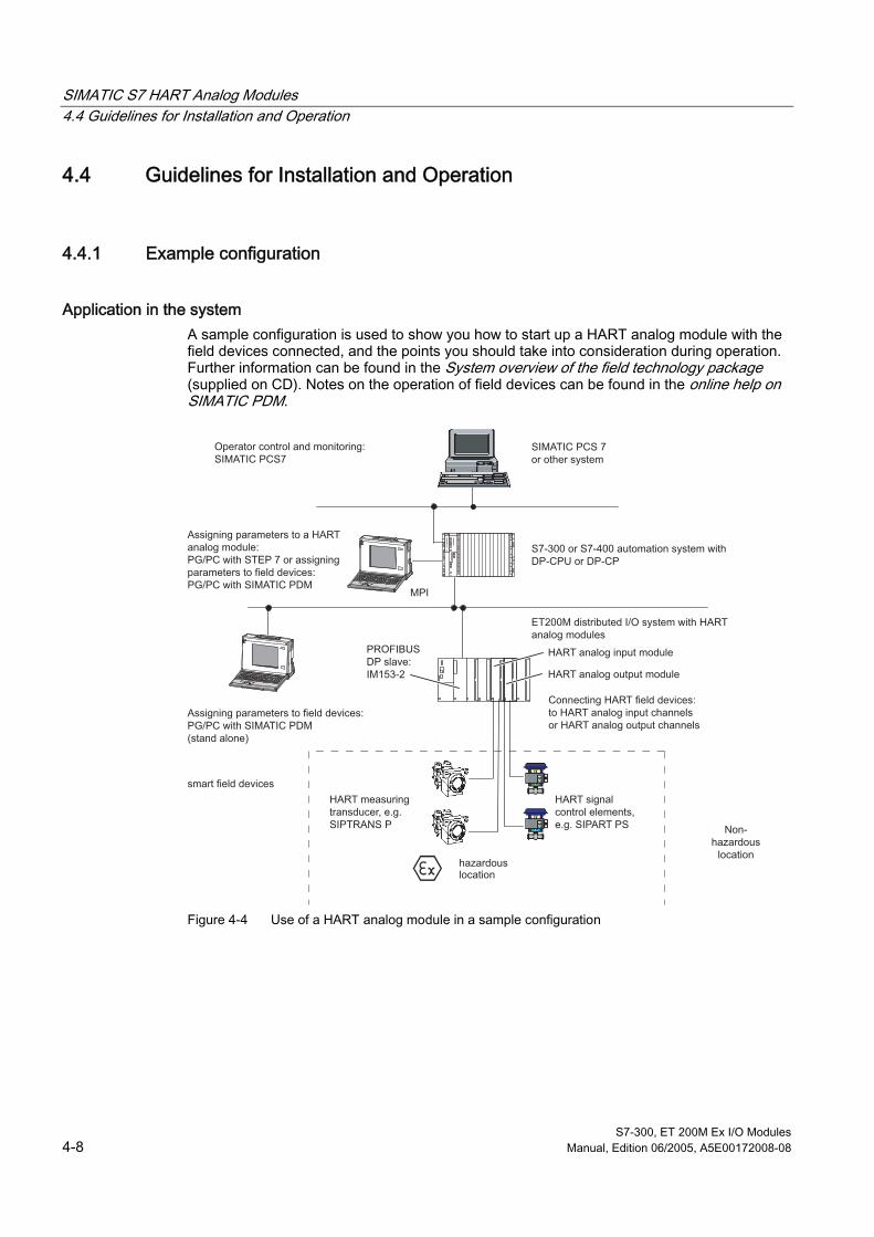
SIMATIC S7 HART Analog Modules 4.4 Guidelines for Installation and Operation
S7-300, ET 200M Ex I/O Modules 4-8 Manual, Edition 06/2005, A5E00172008-08
4.4 4.4 Guidelines for Installation and Operation
4.4.1 Example configuration
Application in the system A sample configuration is used to show you how to start up a HART analog module with the field devices connected, and the points you should take into consideration during operation. Further information can be found in the System overview of the field technology package (supplied on CD). Notes on the operation of field devices can be found in the online help on SIMATIC PDM.
MPI
PROFIBUSDP slave:IM153-2
SIMATIC PCS 7or other system
S7-300 or S7-400 automation system with DP-CPU or DP-CP
HART analog output module
HART analog input module
ET200M distributed I/O system with HART analog modules
Connecting HART field devices:to HART analog input channelsor HART analog output channels
Assigning parameters to field devices:PG/PC with SIMATIC PDM(stand alone)
smart field devices
HART measuring transducer, e.g. SIPTRANS P
HART signal control elements, e.g. SIPART PS
Operator control and monitoring:SIMATIC PCS7
Assigning parameters to a HART analog module:PG/PC with STEP 7 or assigning parameters to field devices:PG/PC with SIMATIC PDM
locationhazardous
Non-hazardous
location
Figure 4-4 Use of a HART analog module in a sample configuration

SIMATIC S7 HART Analog Modules 4.4 Guidelines for Installation and Operation
S7-300, ET 200M Ex I/O Modules Manual, Edition 06/2005, A5E00172008-08 4-9
Note Notes on intrinsically safe installation You must connect the DM 370 dummy module between the IM 153-2 and explosion-proof I/O modules, which include HART I/O modules, whose signal cables lead into the hazardous area. In a distributed configuration with an active backplane bus, you should use the explosion-proof partition (6ES7195-1KA00-0XA0) instead of the dummy module.
4.4.2 Setting Up the HART Analog Module and Field Devices
Installation The HART analog modules are configured and assigned parameters with STEP 7 and the connected smart field devices using the parameter assignment tool SIMATIC PDM:
Configuring and assigning parameters
1. Plug the HART analog module into the ET200M distributed I/O system. "Configure and assign parameters" to the station in the SIMATIC Manager using STEP 7: Start by double-clicking the "Hardware" icon.
2. Select the ET 200M distributed I/O system with an IM153-2 from the PROFIBUS catalog and attach this to the PROFIBUS (note the slave address).
3. Insert the HART analog input module "AI HART" into the desired slot and assign parameters to it: Start by double-clicking the HART analog module in the selected slot.
4. Download the configuration for the station which also contains the parameters for the HART analog module, to the programmable logic controller.
5. To assign field device parameters with SIMATIC PDM, select the channel to which the field device is connected: Begin by double-clicking channel 0 (line 2) or channel 1 (line 3) of the HART analog module.
6. Now you can use the SIMATIC PDM parameter assignment tool to assign parameters to the field devices: SIMATIC PDM provides you with a device- specific parameter assignment interface - depending on the type of field device connected. Field devices must first be made known via the supplied GSE file.

SIMATIC S7 HART Analog Modules 4.4 Guidelines for Installation and Operation
S7-300, ET 200M Ex I/O Modules 4-10 Manual, Edition 06/2005, A5E00172008-08
Modifying the parameters of the field devices Remember that the field devices signal each change in the parameters as a configuration change to the HART analog module. This leads to a diagnostic interrupt on the programmable logic controller, provided this option is enabled. It is advisable to disable the diagnostic interrupt during configuration and parameter assignment.
See also Parameters of HART Analog Modules (Page 4-12)
4.4.3 Operating Phase of the HART Analog Module and Field Devices
Operating phase In the operating phase you must distinguish between the cyclic return of user data, the acyclic HART operation and the cyclic HART communication.
• the cyclic user data, for example measured values, is obtained from the programmable logic controller (PROFIBUS DP master class 1): The user data area exists for this purpose. In the case of the HART analog input module, this is the input area; in the case of the HART analog output module, it is the output area.
• the acyclic intervention for diagnostics and modifying the parameters of the field devices is carried out with the SIMATIC PDM parameter assignment tool (on PROFIBUS DP master class 2) or with a HART hand-held device using HART commands and HART responses.
• You can establish cyclic HART communication by writing / reading a data record in conjunction with the data ready ID in the user data area.
The operating phase
1. Switch the programmable logic controller to "RUN": User data is transmitted cyclically via PROFIBUS DP.
2. You can evaluate the user data cyclically in your user program.
3. You can use the SIMATIC PDM parameter assignment tool for diagnostic purposes and modify the parameters of the field devices: Start by double-clicking channel 0 (line 2) or channel 1 (line 3) of the HART analog module, depending on where the particular field device is connected.
Access to the field devices The HART analog module generally accepts the modification of parameters for the field devices. Access rights can only be allocated using the parameter assignment tool.

SIMATIC S7 HART Analog Modules 4.4 Guidelines for Installation and Operation
S7-300, ET 200M Ex I/O Modules Manual, Edition 06/2005, A5E00172008-08 4-11
Modifying the parameters of the field devices To modify the parameters of the field devices connected to the HART analog modules, proceed as follows:
1. To modify the parameters of a field device, enter a HART command using the SIMATIC PDM parameter assignment tool.
2. This diagnostic interrupt must be acknowledged by the programmable logic controller at the end of the block OB82 before you can access the field device again: The acknowledgement is generally made from the programmable logic controller.
Information on status After you have modified the parameters of a HART field device, the corresponding bit is entered in the device status. This should be regarded as an indicator and not as an error and is reset by the module. For more information, see the "HART status bytes" section. You have to acknowledge the programmable logic controller diagnostic interrupt (OB 82) before you can have access to the field device again.
See also Diagnostic Functions of HART Analog Modules (Page 4-14)
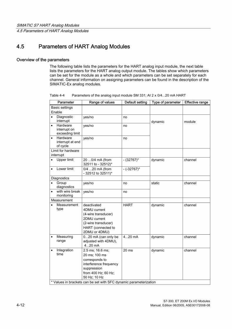
SIMATIC S7 HART Analog Modules 4.5 Parameters of HART Analog Modules
S7-300, ET 200M Ex I/O Modules 4-12 Manual, Edition 06/2005, A5E00172008-08
4.5 4.5 Parameters of HART Analog Modules
Overview of the parameters The following table lists the parameters for the HART analog input module, the next table lists the parameters for the HART analog output module. The tables show which parameters can be set for the module as a whole and which parameters can be set separately for each channel. General information on assigning parameters can be found in the description of the SIMATIC-Ex analog modules.
Table 4-4 Parameters of the analog input module SM 331; AI 2 x 0/4...20 mA HART
Parameter Range of values Default setting Type of parameter Effective range Basic settings Enable
• Diagnostic interrupt
yes/no no
• Hardware interrupt on exceeding limit
yes/no no
• Hardware interrupt at end of cycle
yes/no no
dynamic
module
Limit for hardware interrupt
• Upper limit 20 ...0/4 mA (from 32511 to - 32512)*
- (32767)*
• Lower limit 0/4 ...20 mA (from - 32512 to 32511)*
- (-32767)*
dynamic channel
Diagnostics • Group
diagnostics yes/no no
• with wire break monitoring
yes/no no
static channel
Measurement • Measurement
type deactivated 4DMU current (4-wire transducer) 2DMU current (2-wire transducer) HART (connected to 2DMU or 4DMU)
HART dynamic channel
• Measuring range
0...20 mA (can only be adjusted with 4DMU), 4...20 mA
4...20 mA dynamic channel
• Integration time
2.5 ms; 16.6 ms; 20 ms; 100 ms corresponds to interference frequency suppression from 400 Hz; 60 Hz; 50 Hz; 10 Hz
20 ms dynamic channel
* Values in brackets can be set with SFC dynamic parameterization
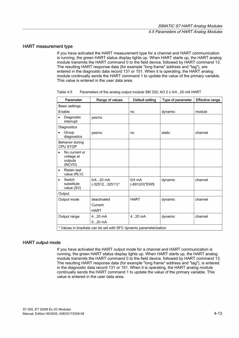
SIMATIC S7 HART Analog Modules 4.5 Parameters of HART Analog Modules
S7-300, ET 200M Ex I/O Modules Manual, Edition 06/2005, A5E00172008-08 4-13
HART measurement type If you have activated the HART measurement type for a channel and HART communication is running, the green HART status display lights up. When HART starts up, the HART analog module transmits the HART command 0 to the field device, followed by HART command 13. The resulting HART response data (for example "long frame" address and "tag"), are entered in the diagnostic data record 131 or 151. When it is operating, the HART analog module continually sends the HART command 1 to update the value of the primary variable. This value is entered in the user data area.
Table 4-5 Parameters of the analog output module SM 332; AO 2 x 0/4...20 mA HART
Parameter Range of values Default setting Type of parameter Effective range Basic settings Enable
no
dynamic
module
• Diagnostic interrupt
yes/no
Diagnostics • Group
diagnostics
yes/no
no
static
channel
Behavior during CPU STOP
• No current or voltage at outputs (NCVO)
• Retain last value (RLV)
• Switch substitute value (SV)
0/4...20 mA (-32512...32511)*
0/4 mA (-6912/0)*EWS
dynamic channel
Output Output mode deactivated
Current HART
HART dynamic channel
Output range 4...20 mA 0...20 mA
4...20 mA dynamic channel
* Values in brackets can be set with SFC dynamic parameterization
HART output mode If you have activated the HART output mode for a channel and HART communication is running, the green HART status display lights up. When HART starts up, the HART analog module transmits the HART command 0 to the field device, followed by HART command 13. The resulting HART response data (for example "long frame" address and "tag"), is entered in the diagnostic data record 131 or 151. When it is operating, the HART analog module continually sends the HART command 1 to update the value of the primary variable. This value is entered in the user data area.
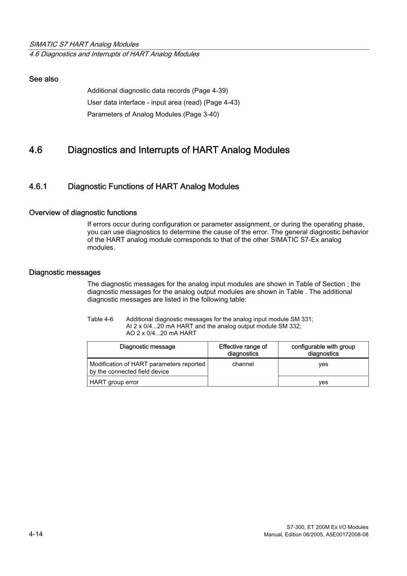
SIMATIC S7 HART Analog Modules 4.6 Diagnostics and Interrupts of HART Analog Modules
S7-300, ET 200M Ex I/O Modules 4-14 Manual, Edition 06/2005, A5E00172008-08
See also Additional diagnostic data records (Page 4-39)
User data interface - input area (read) (Page 4-43)
Parameters of Analog Modules (Page 3-40)
4.6 4.6 Diagnostics and Interrupts of HART Analog Modules
4.6.1 Diagnostic Functions of HART Analog Modules
Overview of diagnostic functions If errors occur during configuration or parameter assignment, or during the operating phase, you can use diagnostics to determine the cause of the error. The general diagnostic behavior of the HART analog module corresponds to that of the other SIMATIC S7-Ex analog modules.
Diagnostic messages The diagnostic messages for the analog input modules are shown in Table of Section ; the diagnostic messages for the analog output modules are shown in Table . The additional diagnostic messages are listed in the following table:
Table 4-6 Additional diagnostic messages for the analog input module SM 331; AI 2 x 0/4...20 mA HART and the analog output module SM 332; AO 2 x 0/4...20 mA HART
Diagnostic message Effective range of diagnostics
configurable with group diagnostics
Modification of HART parameters reported by the connected field device
yes
HART group error
channel
yes
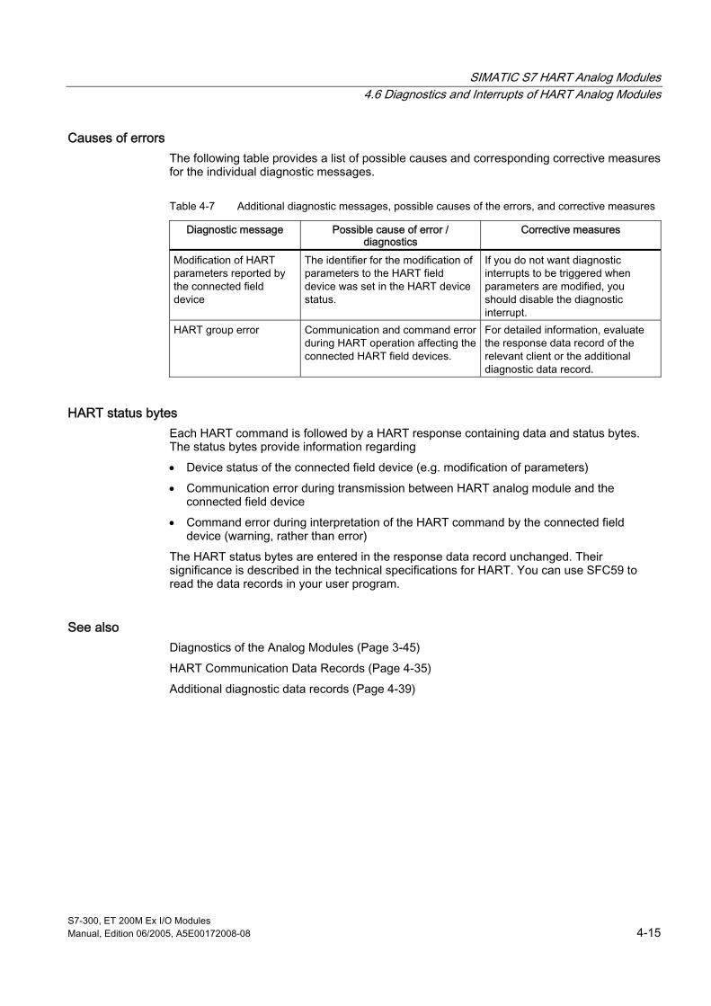
SIMATIC S7 HART Analog Modules 4.6 Diagnostics and Interrupts of HART Analog Modules
S7-300, ET 200M Ex I/O Modules Manual, Edition 06/2005, A5E00172008-08 4-15
Causes of errors The following table provides a list of possible causes and corresponding corrective measures for the individual diagnostic messages.
Table 4-7 Additional diagnostic messages, possible causes of the errors, and corrective measures
Diagnostic message Possible cause of error / diagnostics
Corrective measures
Modification of HART parameters reported by the connected field device
The identifier for the modification of parameters to the HART field device was set in the HART device status.
If you do not want diagnostic interrupts to be triggered when parameters are modified, you should disable the diagnostic interrupt.
HART group error Communication and command error during HART operation affecting the connected HART field devices.
For detailed information, evaluate the response data record of the relevant client or the additional diagnostic data record.
HART status bytes Each HART command is followed by a HART response containing data and status bytes. The status bytes provide information regarding
• Device status of the connected field device (e.g. modification of parameters)
• Communication error during transmission between HART analog module and the connected field device
• Command error during interpretation of the HART command by the connected field device (warning, rather than error)
The HART status bytes are entered in the response data record unchanged. Their significance is described in the technical specifications for HART. You can use SFC59 to read the data records in your user program.
See also Diagnostics of the Analog Modules (Page 3-45)
HART Communication Data Records (Page 4-35)
Additional diagnostic data records (Page 4-39)

SIMATIC S7 HART Analog Modules 4.6 Diagnostics and Interrupts of HART Analog Modules
S7-300, ET 200M Ex I/O Modules 4-16 Manual, Edition 06/2005, A5E00172008-08
4.6.2 Interrupts of the HART Analog Modules
Overview of the interrupts The general interrupt behavior of the HART analog module corresponds to that of the other SIMATIC S7-Ex analog modules. You can set parameters to enable or disable any interrupt.
Hardware interrupts with AI HART There are two types of hardware interrupt: "Hardware interrupt when limit value exceeded" and "Hardware interrupt on end of cycle." When a hardware interrupt is triggered, you can evaluate the local data in OB40:
Table 4-8 Local data in OB40
Local data OB40
Bit 7 ...4 Bit 3 Bit 2 Bit 1 Bit 0 Limit value
Byte 0 '0' '0' '0' Channel 1 Channel 0 Upper limit exceeded
Byte 1 '0' '0' '0' Channel 1 Channel 0 Lower limit exceeded
Byte 2 '0' '0' '0' '0' '0' Not relevant Byte 3 '0' '0' '0' '0' '0' Not relevant
At the end of the cycle all the bits in bytes 0-3 of the additional information for OB40 which are not reserved for channels 0 and 1 are set to "1". You can use the reserved bits to evaluate whether the upper or lower limit set has been exceeded for a particular channel: if a limit has been exceeded, a "1" is displayed instead of a "0".
See also Parameters of HART Analog Modules (Page 4-12)
Interrupts of Analog Modules (Page 3-50)
SIMATIC S7 HART Analog Modules 4.7 HART analog input modules SM 331; AI 2 x 0/4...20 mA HART (6ES7331-7TB00-0AB0)
S7-300, ET 200M Ex I/O Modules Manual, Edition 06/2005, A5E00172008-08 4-17
4.7 4.7 HART analog input modules SM 331; AI 2 x 0/4...20 mA HART (6ES7331-7TB00-0AB0)
Order Number 6ES7331-7TB00-0AB0
Features The analog input module SM 331, AI 2 x 0/4 ... 20 mA HART is characterized by the following features:
• 2 inputs in 2 channel groups
• 2 outputs to power 2-wire measuring transducers
• The measured value resolution can be set for each channel individually (see "Analog values and resolution").
• Measurement type can be selected for each channel:
– HART (2-wire transducer or 4-wire transducer for current)
– 2-wire or 4-wire transducer for current (used without HART)
– Channel deactivated
• arbitrary measuring range selection for each channel
– 0 ... 20 mA (only for 4-wire transducers used without HART)
– 4 ... 20 mA
• Settings for diagnostics and diagnostic interrupt
– Group diagnostics
– Additional wire break monitoring
– Diagnostic interrupt
• Settings for hardware interrupt
– Channels 0 and 1 with limit monitoring: hardware interrupt can be set to trigger if limit is exceeded
– hardware interrupt can be set for cycle end
• Galvanic isolation
– Channels electrically isolated from each other
– Channels electrically isolated from CPU and load voltage L+

SIMATIC S7 HART Analog Modules 4.7 HART analog input modules SM 331; AI 2 x 0/4...20 mA HART (6ES7331-7TB00-0AB0)
S7-300, ET 200M Ex I/O Modules 4-18 Manual, Edition 06/2005, A5E00172008-08
Analog values and resolution The representation of the analog values is the same as for the analog input module SM 331; AI 4 x 0/4...20 mA. The resolution of the measured value is directly dependent on the selected integration time, i.e. the greater the integration time selected for an analog input channel, the more precise the resolution of the measured value.
• 10 Bit + sign (integration time 2.5 ms)
• 13 Bit + sign (integration time 16.6 ms / 20 ms)
• 15 Bit + sign (integration time 100 ms)
Table 4-9 Parameters of the analog input module SM 331; AI 2 x 0/4...20 mA HART
selected output mode Output range Current from 0 to 20 mA
from 4 to 20 mA
Integration times when HART is used If you use measuring transducers with the HART protocol, it is advisable to assign integration times of 16.6, 20 or 100 ms, in order to minimize the influence of the modulating alternating current on the measuring signal.
Default settings The HART measurement mode is set as default. There are other default settings for integration time, diagnostics, interrupts. The HART analog module uses these settings, unless you modify them using STEP 7.
Wire break monitoring Wire break recognition is not possible for the current range 0 to 20 mA.
• For the current range 4 to 20 mA, if the input current falls below I ≤ 3.6 mA this is interpreted as a wire break and a diagnostic interrupt is triggered (provided the interrupt is enabled).
Inserting and removing modules The HART analog modules support the function "Change modules during operation." However, it is only possible to evaluate the insert / remove module interrupts with a S7/M7 400 CPU master and active backplane bus in the ET 200M.
Operation with standard master When operating with a standard master you must note the following restrictions:
• Parameter assignment with COM PROFIBUS (GSE file or type file required)
• Restricted evaluation when "inserting or removing"

SIMATIC S7 HART Analog Modules 4.7 HART analog input modules SM 331; AI 2 x 0/4...20 mA HART (6ES7331-7TB00-0AB0)
S7-300, ET 200M Ex I/O Modules Manual, Edition 06/2005, A5E00172008-08 4-19
Terminal diagram of the SM 331; AI 2 x 0/4...20 mA
ADU
SF
(2-wire) CH0
L0 +
M0+
M0+
M0-
M1+
M1+
X 23 4
331-7TB00-0AB0
SF
[EEx ib] IIC
SM 331
H0
F0
x
F (0.1)
5V internal
M internal
2-w
ire
+
- 4-w
ire
2-w
ire
M
L +M
390 Ω
1
2
3
4
5
6
7
8
9
10
11
12
13
14
15
16
17
18
19
20
L +M
50 Ω
M
L +L +
L +
L1+
AI 2 x 0 / 4...20 mA HART2-wire measuring transducer
4-wire measuring transducer
M
F1
H1
H (0.1)
+
- 4-w
ire
200 Ω
200 Ω
390 Ω
(2-wire)
(4-wire)
(4-wire)
(2-wire) CH1
(2-wire)
(4-wire)M1- (4-wire)
MO-DEM
MO-DEM
50 Ω
II (2) G
Input 0
SF Group error indicator [red]
Galvanic isolation
Galvanic isolation
H (0. 1) HART status indication [green]
F (0. 1) channel-specific fault indication [red]
Input 1
Logic and back-
plane bus interfac-
ing
Figure 4-5 Module view and block diagram of SM 331; AI 2 x 0/4...20 mA HART
Note Observe the prerequisites for an intrinsically safe installation.
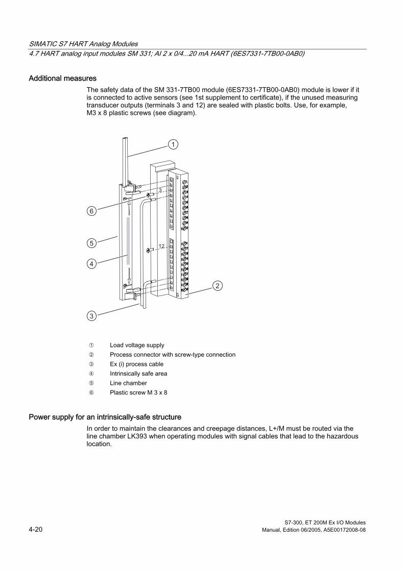
SIMATIC S7 HART Analog Modules 4.7 HART analog input modules SM 331; AI 2 x 0/4...20 mA HART (6ES7331-7TB00-0AB0)
S7-300, ET 200M Ex I/O Modules 4-20 Manual, Edition 06/2005, A5E00172008-08
Additional measures The safety data of the SM 331-7TB00 module (6ES7331-7TB00-0AB0) module is lower if it is connected to active sensors (see 1st supplement to certificate), if the unused measuring transducer outputs (terminals 3 and 12) are sealed with plastic bolts. Use, for example, M3 x 8 plastic screws (see diagram).
1
2
3
4
5
6
3
12
➀ Load voltage supply ➁ Process connector with screw-type connection ➂ Ex (i) process cable ➃ Intrinsically safe area ➄ Line chamber ➅ Plastic screw M 3 x 8
Power supply for an intrinsically-safe structure In order to maintain the clearances and creepage distances, L+/M must be routed via the line chamber LK393 when operating modules with signal cables that lead to the hazardous location.

SIMATIC S7 HART Analog Modules 4.7 HART analog input modules SM 331; AI 2 x 0/4...20 mA HART (6ES7331-7TB00-0AB0)
S7-300, ET 200M Ex I/O Modules Manual, Edition 06/2005, A5E00172008-08 4-21
Technical specifications of the SM 331; AI 2 x 0/4...20 mA HART
Dimensions and Weight Dimensions W x H x D (mm) 40 x 125 x 120 Weight approx. 260 g Module-specific data Number of inputs Number of power outputs
2 2
Line length, shielded max. 400 m KEMA protection (see Appendix "Certificates of Conformity")
II 3 (2) G EEX nA [lib] IIC T4
Test number KEMA 97ATEX3039 X FM protection (see Appendix "Standards and Licenses")
Class I, Division 2, Group A, B, C, D T4 Class I, Zone 2, Group IIC T4
Voltages, currents, potentials Bus power supply Rated load voltage L+ • Reverse voltage protection
DC 5 V DC 24 V yes
Voltage supply for 2-wire transducer • short-circuit proof
yes (approx. 30 mA)
Galvanic isolation • between the channels and backplane bus yes • between the channels yes • between the channels and load voltage L+ yes • between the backplane bus and load
voltage L+ yes
Permissible potential difference (UISO) for signals from a hazardous area • between the channels and backplane bus DC 60 V
AC 30 V • between the channels and load voltage L+ DC 60 V
AC 30 V • between the channels DC 60 V
AC 30 V • between the backplane bus and load
voltage L+ DC 60 V AC 30 V
Permissible difference in potential (UISO) with signals from the non-hazardous area • between the channels and backplane bus DC 400 V
AC 250 V • between the channels and load voltage L+ DC 400 V
AC 250 V • between the channels DC 400 V
AC 250 V • between the backplane bus and load
voltage L+ DC 75 V AC 60 V

SIMATIC S7 HART Analog Modules 4.7 HART analog input modules SM 331; AI 2 x 0/4...20 mA HART (6ES7331-7TB00-0AB0)
S7-300, ET 200M Ex I/O Modules 4-22 Manual, Edition 06/2005, A5E00172008-08
Insulation tested • Channels to backplane bus and load
voltage L+ with AC 1500 V
• Channels to each other with AC 1500 V • Backplane bus with respect to load voltage L+ with DC 500 V Current input • from backplane bus max. 100 mA • from load voltage L+ max. 180 mA Module power loss typical 4.5 W Safety specifications (see EU special test certificate KEMA 01ATEX1060 X in Appendix under "Certificates of Conformity") Type of protection to EN 50020 [EEx ib] IIC Maximum values per channel • U0 (no-load output voltage) max. 26 V • I0 (short-circuit current) max. 96.1 mA • P0 (load power) max. 511 mW • L0 (permissible external inductance) max. 3 mH • C0 (permissible external capacity) max. 62 nF • Um (fault voltage) max. DC 250V • Ta (permissible ambient temperature) 0...60°C Analog value formation Measuring principle SIGMA-DELTA Integration time/conversion time/resolution (per channel)
• configurable yes yes yes yes • Integration time in ms 2,5 16 2/3 20 100 • Basic conversion time incl. integration time in
ms (1 channel enabled) 2,5 16 2/3 20 100
• Basic conversion time including integration time in ms (2 channels enabled)
7,5 50 60 300
• Resolution in bit + sign (incl. overrange) 10+ sign 13+ sign 13+ sign 15+sign • Interference voltage suppression for interference
frequency f1 in Hz 400 60 50 10
Interference suppression, error limits Interference voltage suppression for f = n x (f1 ± 1 %), (f1 = interference frequency) • Common-mode interference
channels with respect to earth terminal of the CPU (UISO < 60 V)
> 130 dB
• Normal-mode interference (measured value + interference must be within the input range 0 to 22 mA)
> 60 dB
Crosstalk attenuation between inputs (UISO < 60 V)
> 130 dB
Operational limit (in total temperature range, referred to input range) • from 0/4 to 20 mA ± 0,45 % Basic error limit (operational limit at 25 °C, referred to input range) • from 0/4 to 20 mA ± 0,1 %
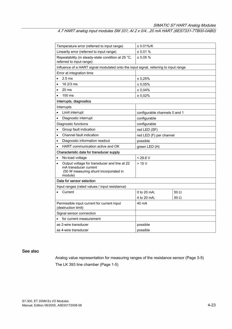
SIMATIC S7 HART Analog Modules 4.7 HART analog input modules SM 331; AI 2 x 0/4...20 mA HART (6ES7331-7TB00-0AB0)
S7-300, ET 200M Ex I/O Modules Manual, Edition 06/2005, A5E00172008-08 4-23
Temperature error (referred to input range) ± 0.01%/K Linearity error (referred to input range) ± 0,01 % Repeatability (in steady-state condition at 25 °C, referred to input range)
± 0,05 %
Influence of a HART signal modulated onto the input signal, referring to input range Error at integration time • 2.5 ms ± 0,25% • 16 2/3 ms ± 0,05% • 20 ms ± 0,04% • 100 ms ± 0,02% Interrupts, diagnostics Interrupts • Limit interrupt configurable channels 0 and 1 • Diagnostic interrupt configurable Diagnostic functions configurable • Group fault indication red LED (SF) • Channel fault indication red LED (F) per channel • Diagnostic information readout possible • HART communication active and OK green LED (H) Characteristic data for transducer supply • No-load voltage < 29.6 V • Output voltage for transducer and line at 22
mA transducer current (50 W measuring shunt incorporated in module)
> 15 V
Data for sensor selection Input ranges (rated values / input resistance) • Current 0 to 20 mA;
4 to 20 mA; 50 Ω 50 Ω
Permissible input current for current input (destruction limit)
40 mA
Signal sensor connection • for current measurement as 2-wire transducer as 4-wire transducer
possible possible
See also Analog value representation for measuring ranges of the resistance sensor (Page 3-5)
The LK 393 line chamber (Page 1-5)

SIMATIC S7 HART Analog Modules 4.8 HART analog output module SM 332; AO 2 x 0/4...20 mA HART (6ES7332-5TB00-0AB0)
S7-300, ET 200M Ex I/O Modules 4-24 Manual, Edition 06/2005, A5E00172008-08
4.8 4.8 HART analog output module SM 332; AO 2 x 0/4...20 mA HART (6ES7332-5TB00-0AB0)
Order Number 6ES7332-5TB00-0AB0
Features The HART analog output module has the following features:
• 2 outputs in 2 channel groups
• Resolution 12 bit (+ sign)
• Measurement type can be selected for each channel:
– Current output with HART
– Current without HART usage
– Channel deactivated
• output range selectable for each channel
– 0...20 mA (without HART usage)
– 4...20 mA
• Settings for diagnostics and diagnostic interrupt
– Group diagnostics
– Diagnostic interrupt
• Galvanic isolation
– Channels electrically isolated from each other
– Channels electrically isolated from CPU and load voltage L+
• Readback capability of the analog outputs
Analog values and resolution The representation of the analog values is the same as for the analog output module SM 332; AO 4 x 0/4...20 mA. The resolution of the output value for the HART analog output module is, however, 12 bit.
Table 4-10 Output ranges of the analog output module SM 332; AO 4 x 0/4...20 mA
selected output mode Output range Current from 0 to 20 mA
from 4 to 20 mA

SIMATIC S7 HART Analog Modules 4.8 HART analog output module SM 332; AO 2 x 0/4...20 mA HART (6ES7332-5TB00-0AB0)
S7-300, ET 200M Ex I/O Modules Manual, Edition 06/2005, A5E00172008-08 4-25
Default settings The HART output mode is set as default. There are other default settings for integration time, diagnostics, interrupts. The HART analog output module uses these settings, unless you modify them using STEP 7.
Wire break monitoring Wire break monitoring is possible for the current range 0/4 to 20 mA.
Conditions: A minimum output current of >500 µA is required.
Inserting and removing modules The HART analog modules support the function "Change modules during operation." However, it is only possible to evaluate the insert / remove module interrupts with a S7/M7 400 CPU master and active backplane bus in the ET 200M.
Operation with standard master When operating with a standard master you must note the following restrictions:
• Parameter assignment with COM PROFIBUS (GSE file or type file required)
• Restricted evaluation when "inserting or removing"
How a fall in the load voltage affects diagnostic messages If the 24 V load voltage falls below the permitted rated range (< 20.4 V), there may be a reduction in the output current at connected loads 650 Ω and output currents > 20 mA before a diagnostic message is transmitted.
Readback capability The analog outputs can be read back in the user data range (+ sign) with a resolution of 8 bit. Please note that the readback analog output is only available after a conversion time which varies with the precision desired.

SIMATIC S7 HART Analog Modules 4.8 HART analog output module SM 332; AO 2 x 0/4...20 mA HART (6ES7332-5TB00-0AB0)
S7-300, ET 200M Ex I/O Modules 4-26 Manual, Edition 06/2005, A5E00172008-08
Wiring diagram for the SM 332; AO 2 x 0/4...20 mA HART
L +L +
390 Ω
L +M
DA
X 23 4
332-5TB00-0AB0
SF
[EEx ib] IIC
SM 332
H0
F0
x
MM
L +
AI 2 x 0 / 4...20 mA HART
M
F1
H1
H (0.1)
CH1
0...500 Ω
CH0
0...500 Ω CH0
QI 0
M 0-
QI 1
CH1M 1-SF
F (0.1)
II (2) G
50 Ω
390 Ω
L +M
DA
HART
HART
50 Ω
Output 0
Modem
Modem
Output 1
SF Group error indicator [red]
Galvanic isolation
Isolation amplifier
Digital / analog transformer
Logic and backplane
bus interfac-
ing
H (0. 1) HART status indication [green]
F (0. 1) channel-specific fault indication [red]
Figure 4-6 Module view and block diagram of SM 332; AO 2 x 0/4...20 mA HART
Note Observe the prerequisites for an intrinsically safe installation.
Power supply for an intrinsically-safe structure In order to maintain the clearances and creepage distances, L+/M must be routed via the line chamber LK393 when operating modules with signal cables that lead to the hazardous location.

SIMATIC S7 HART Analog Modules 4.8 HART analog output module SM 332; AO 2 x 0/4...20 mA HART (6ES7332-5TB00-0AB0)
S7-300, ET 200M Ex I/O Modules Manual, Edition 06/2005, A5E00172008-08 4-27
Unswitched output channels To ensure that the unswitched output channels of the analog output module SM 332; AO 2 x 0/4...20 mA HART are without current or voltage, you must deactivate them. You can deactivate an output channel in STEP 7 using the "Output" parameter block.
Technical specifications of the SM 332; AO 2 x 0/4...20 mA HART
Dimensions and Weight Dimensions W x H x D (mm) 40 x 125 x 120 Weight approx. 280 g Module-specific data Number of outputs 2 Line length, shielded max. 400 m KEMA protection (see Appendix "Certificates of Conformity")
II 3 (2) G EEX nA [lib] IIC T4
Test number KEMA 97ATEX2359 X FM protection (see Appendix "Standards and Licenses")
Class I, Division 2, Group A, B, C, D T4 Class I, Zone 2, Group IIC T4
Voltages, currents, potentials Bus power supply Rated load voltage • Reverse voltage protection
5 V DC 24 V DC yes
Galvanic isolation • between the channels and backplane bus yes • between the channels yes • between the channels and load voltage L+ yes • between the backplane bus and load voltage
L+ yes
Permissible difference in potential (UISO) for signals from a hazardous area • between the channels and backplane bus DC 60 V
AC 30 V • between the channels and load voltage L+ DC 60 V
AC 30 V • between the channels DC 60 V
AC 30 V • between the backplane bus and load voltage
L+ DC 60 V AC 30 V
Permissible difference in potential (UISO) for signals from non-hazardous area • between channels and backplane bus DC 400 V
AC 250 V • between channels and load voltage L+ DC 400 V
AC 250 V • between the channels DC 400 V
AC 250 V • between the backplane bus and load
voltage L+ DC 75 V AC 60 V

SIMATIC S7 HART Analog Modules 4.8 HART analog output module SM 332; AO 2 x 0/4...20 mA HART (6ES7332-5TB00-0AB0)
S7-300, ET 200M Ex I/O Modules 4-28 Manual, Edition 06/2005, A5E00172008-08
Insulation tested • Channels to backplane bus and load
voltage L+ with 1500 V AC
• Channels to each other with 1500 V AC • Backplane bus with respect to load voltage L+ with 500 V DC • Channels with respect to shield with 500 V DC Current input from backplane bus max. 100 mA from load voltage L+ (at rated data) max. 150 mA Module power loss typical 3.5 W Analog value formation Output value Resolution (incl. overrange) 12 bit (+ sign) Cycle time (all channels) 5 ms Transient recovery time • for resistive load 2.5 ms • for inductive load 2.5 ms • for capacitive load 4 ms Switch substitute values yes, configurable Readback value Resolution 8 bit (+ sign) Conversion time (per channel) 40 ms Interference suppression, error limits Crosstalk attenuation between outputs > 130 dB Operational limit (in total temperature range, referred to output range)
± 0,55 %
Basic error limit (operational limit at 25 °C, referred to output range)
± 0,15 %
Temperature error (referred to output range) ± 0.01 %/K Linearity error (referred to output range) ± 0,03 % Repeatability (in steady-state condition at 25 °C, referred to output range)
± 0,005 %
Output ripple; range 0 to 50 kHz (referred to output range)
± 0,02 %
Interrupts, diagnostics Interrupts • Diagnostic interrupt configurable Diagnostic functions configurable • Group fault indication red LED (SF) • Channel fault indication red LED (F) per channel • Diagnostic information readout possible monitoring for • Wire break
from output value yes > 0.5 mA
HART communication active and OK green LED (H)

SIMATIC S7 HART Analog Modules 4.8 HART analog output module SM 332; AO 2 x 0/4...20 mA HART (6ES7332-5TB00-0AB0)
S7-300, ET 200M Ex I/O Modules Manual, Edition 06/2005, A5E00172008-08 4-29
Safety specifications (see EU special test certificate KEMA 97ATEX2359 X in Appendix under "Certificates of Conformity") Maximum values of the output circuits (per channel)
• U0 (no-load output voltage) max. 19 V • I0 (short-circuit current) max. 66 mA • P0 (load power) max. 506 mW • L0 (permissible external inductance) max. 7.5 mH • C0 (permissible external capacity) max. 230 nF • Um (fault voltage) max. DC 60V • Ta (permissible ambient temperature) max. 60°C Data for sensor selection Output ranges (rated values) • Current from 0 to 20 mA
from 4 to 20 mA Load impedance (in rated range of output) • for current outputs
– resistive load – inductive load
max. 650 Ω max. 7.5 mH1
• capacitive load max. 230 nF1 Current output • No-load voltage max. 19 V Destruction limit for externally applied voltages / currents
Voltages max. + 17 V / - 0.5V Current max. + 60 mA / - 1A Connection of actuators • for current output
2-wire connection yes
1 KEMA approval limitations can be set as the load when used in non-ex areas • inductive load max. 15 mH • capacitive load max. 3 µF *) *) however, HART communication no longer possible
See also The LK 393 line chamber (Page 1-5)
Analog Value Representation for the Output Ranges of Analog Outputs (Page 3-20)
Parameters of HART Analog Modules (Page 4-12)

SIMATIC S7 HART Analog Modules 4.9 Data record interface
S7-300, ET 200M Ex I/O Modules 4-30 Manual, Edition 06/2005, A5E00172008-08
4.9 4.9 Data record interface
4.9.1 Overview of the data record interface and user data
Introduction In this section you will find the specific data which you need for parameter assignment, diagnostics and for HART communication, when using standard STEP 7 applications or if you want to use your own software tool for HART communication.
The cyclic user data is described at the end of the chapter.
Overview of the data record interface The HART analog modules use data records as the input/output interface. The records are used for the following applications:
• writing the parameters to the module
• reading the diagnostic data of the module
• transmitting the HART communication data
• reading the additional diagnostic data for HART
• writing the additional parameters for HART
Configure and assign parameters using STEP 7 You can configure and assign parameters to the HART analog modules using STEP 7. The online help will assist you with this.
Certain additional functions for writing parameters and reading diagnostic data can be integrated in your user program with SFCs.
Overview of user data The user data range of the HART analog modules includes the following for both channel 0 and channel 1:
• Current as analog input value or analog output value
• Primary value in HART format (measured value or manipulated value)
• Identifiers for clients, to indicate that new data can be collected.
Relative addresses are shown in the description of the user data. You can determine the module address to be added to the relative address using the STEP 7 application "Configuring and Assigning Parameters."

SIMATIC S7 HART Analog Modules 4.9 Data record interface
S7-300, ET 200M Ex I/O Modules Manual, Edition 06/2005, A5E00172008-08 4-31
4.9.2 Parameter Data Records
Structure of the parameter data records for the HART analog inputs The following diagrams show data record 0 for the static parameters and data record 1 for the dynamic parameters for AI HART and AO HART. In the case of S5 and the standard master, all the parameters are transferred to data record 0.
Byte 2
Byte 3
Byte 4
Byte 5
Byte 07 6 05 4 3 2 1
0 00 0 0
Byte 1 0 00 0
2#00 = 2.5 ms2#01 = 16.7 ms2#10 = 20 ms2#11 = 100 ms
Byte 6toByte 9
Byte 10toByte 13
Byte 0
7 6 05 4 3 2 1
0 00 00 0
Byte 1 0 00 00 0
must be 0
must be 0
Parameter data record 0
Parameter data record 1
Group diagnosticsWire break monitoring
Enable
Integration time
Hardware interrupt at end of cycleEnable diagnostic interrupt
Enable limit interrupt
Channel 0
Channel 0
Channel 1
Channel 1
Upper limit channel 1Lower limit channel 1
Upper limit channel 0Lower limit channel 0
see followingtable 4-11
in each case, first "High-Byte," then "Low-Byte"
M. type, m. range, channel 1
M. type, m. range, channel 0
Figure 4-7 Parameters of the HART analog input module
Table 4-11 Codes for the measurement type and measuring range for the HART analog input module
Measurement type Code Measuring range Code deactivated 2#0000 deactivated 2#0000 4-wire measuring transducer 2#0010 from 0 to 20 mA
from 4 to 20 mA 2#0010 2#0011
2-wire measuring transducer 2#0011 4 to 20 mA 2#0011 HART (2-wire or 4-wire transducer can be connected.)
2#0111 4 to 20 mA HART All commands permitted, and monodrop operation.
2#1100

SIMATIC S7 HART Analog Modules 4.9 Data record interface
S7-300, ET 200M Ex I/O Modules 4-32 Manual, Edition 06/2005, A5E00172008-08
Structure of the parameter data records for HART analog outputs The following diagram shows data record 0 for the static parameters and data record 1 for the dynamic parameters. In the case of S5 and the standard master, all the parameters are transferred to data record 0.
Byte 2
Byte 3
Byte 4
Byte 5
Byte 07 6 05 4 3 2 1
00 00 00 0
Byte 1 0 00 0 0 0
Byte 6toByte 9
Byte 10toByte 13
Byte 0
7 6 05 4 3 2 1
0 00 00 0
Byte 1 0 00 00 0 0 0
Parameter data record 0
Parameter data record 1
Group diagnostics
Enable
must be 0
must be 0
must be 0must be 0
must be 0must be 0
Behavior during CPU STOP (OD active)
Enable diagnostic interrupt
Channel 0
Channel 0
Channel 1
Channel 1
Subst. value channel 0Subst. value channel 1
reservedreserved
reservedreserved
see followingtable 4-12
2#0 = subst. value*2#1 = last value
in each case, first "High-Byte," then "Low-Byte"
M. type, m. range, channel 1
M. type, m. range, channel 0
Figure 4-8 Parameters of the analog output module
* For the substitute value -6912 (E500 Hex) the outputs will be disabled.
Table 4-12 Codes for the measurement type and measurement range for the HART analog output module
Output mode Code Output range Code deactivated 2#0000 deactivated 2#0000 Current output without HART 2#0010 from 0 to 20 mA
from 4 to 20 mA 2#0010 2#0011
Current output with HART 2#0111 4 to 20 mA HART All commands permitted, and monodrop operation.
2#1100

SIMATIC S7 HART Analog Modules 4.9 Data record interface
S7-300, ET 200M Ex I/O Modules Manual, Edition 06/2005, A5E00172008-08 4-33
4.9.3 Diagnostic data records
Structure and contents of the diagnostic data The diagnostic data for a module can be up to 16 bytes long and consist of data records 0 and 1:
• Data record 0 contains system-specific diagnostic data: 4 bytes. It is set on a system-wide basis and applies for both HART analog inputs and outputs.
• Data record 1 contains
– 4 bytes of diagnostic data for an S7-300 which are also in data record 0 and
– up to 12 bytes of module-class specific diagnostic data.
Diagnostic data record DS0 / DS1
Byte 1
7 6 05 4 3 2 1
00 011
Byte 2
7 6 05 4 3 2 1
0
Byte 37 6 05 4 3 2 1
0 0
00
00 0 00
Byte 0
7 6 05 4 3 2 1
0 Module fault
Module class CP
Channel information available
Error (internal)
Processor failure
EPROM error
RAM error
ADU/DAU error
Fuse blown
Hardware interrupt lost (only with AI HART)
Error (external)
Channel error occurred
external auxiliary voltage missing
incorrect parameters in the module
module-internal supply voltage failure
parameters missing(set immediately after voltage recovery)
Cycle-time monitoring for the module responded (“watch dog”)
Figure 4-9 Diagnostic data: data record 0/1

SIMATIC S7 HART Analog Modules 4.9 Data record interface
S7-300, ET 200M Ex I/O Modules 4-34 Manual, Edition 06/2005, A5E00172008-08
Diagnostic data: data record DS1 The following diagram shows the contents of bytes 4 to 9 of the diagnostic data.
Byte 4
7 6 05 4 3 2 1
Byte 5
Byte 6
Byte 7
7 6 05 4 3 2 1
7 6 05 4 3 2 1
7 6 05 4 3 2 1
7 6 05 4 3 2 1
0 00 0 0 0 01
0
0 00 0 0 1 00
Byte 8
7 6 05 4 3 2 1
Byte 9
0 0
0 00 00 0
Channel type B#16#61: HART analog input module
Identifier for channel 0 or channel group 0
Configuration / parameter error
Measuring range underflow (only with analog input)
Measuring range overflow (only with analog input)
Identifier for channel 1 or channel group 1
Channel type B#16#63: HART analog output module
Number of diagnostic bits that themodule outputs per channel:B#16#08
Number of channels of the same typein one module:B#16#02
channel-specific error occurred, if following identifier =1:
channel-specific error for channel 1:Assignment corresponds to channel 0,see Byte 8
Modification of HART parameters reported by the connected field device
HART channel error, further information about HART response data record or additional diagnostics
channel-specific error for channel 0:
Wire break
Figure 4-10 Diagnostic data: data record 1
Note Please note the following points regarding diagnostic data:
If a HART channel error occurs, you can obtain further information by using SFC59 to read the status in the HART response data record for the relevant client or the additional diagnostic data record for the relevant channel.

SIMATIC S7 HART Analog Modules 4.9 Data record interface
S7-300, ET 200M Ex I/O Modules Manual, Edition 06/2005, A5E00172008-08 4-35
See also HART Communication Data Records (Page 4-35)
Additional diagnostic data records (Page 4-39)
4.9.4 HART Communication Data Records
Transfer data records HART communication can be operated by up to 7 clients each using two separate channels. There are 14 separate data transfer areas for this purpose, 7 for channel 0 and 7 for channel 1. Each transfer area consists of a command data record and a response data record.
Coordination rules for HART communication • Each client / channel is allocated fixed data record numbers:
Channel Client / data record 1 2 3 4 5 6 7
0 Command 10 14 18 22 26 30 34 0 Response 12 16 20 24 28 32 36 1 Command 50 54 58 62 66 70 74 1 Response 52 56 60 64 68 72 76
• Each client may only use the data record numbers allocated to its transfer area.
• For example, for client 6, channel 0: the command is data record 30 and the response is data record 32.
• After a client has written a command data record, it must read the response data record before it can write another command data record.
• The transfer area of each client is allocated a data ready bit in the user data area, which is set when new data can be collected.
• In Master Class 2 the client can evaluate the "processing state" in the response data record: if the "processing state" indicates "successful" or "error," the data record contains current response data or error bits respectively.
• The data record must always be read completely, as, after the first reading, the data record of the module can be changed.
• The status section of the response data record provides information on any errors that have occurred.
• The HART burst mode cannot be used by more than one client at any one time (that is, only one client can set this operating mode with a command).

SIMATIC S7 HART Analog Modules 4.9 Data record interface
S7-300, ET 200M Ex I/O Modules 4-36 Manual, Edition 06/2005, A5E00172008-08
Structure of the command data record The following diagram shows the structure of the data record, which you can use to write a command in the transfer area of a client. The HART analog module transmits the command to the connected HART field device.
Byte 0
7 6 05 4 3 2 1
0 0
Byte 3
Byte 239
Byte 1
Byte 2
.
.
.
always 0 ("monodrop," 1 field device per channel)
1=inseparable command sequence
to
1=module command,0=HART command
Command number - number of bytes for command (can be taken from the HART command syntax)
Command data according to HART specificationLength: No. of bytesmax. 237 bytes
Figure 4-11 Command data record of the HART analog module
Notes on the command The same client must not send a second command until the response to any previous command has been read. If you want to prevent commands from another client being processed in between, you must set the bit "inseparable command sequence" in your command:
• The inseparable command sequence is maintained as long as the bit "inseparable command sequence" is set.
• The inseparable command sequence is terminated if the bit "inseparable command sequence" is not set, or automatically after 10 seconds by the module.
• While an inseparable command sequence is set for one client, one command from each of the other clients can be stored temporarily in the buffer. The stored commands are processed once the inseparable command sequence has been terminated.
Notes on response To read the response data record you must make sure that an up-to-date response data record has arrived:
• If the processing state in the response data record indicates "successful" or "error," the data record contains current response data or error messages respectively.
• Alternatively you can evaluate the "data ready" in the user data area: the transfer area of each client is allocated a bit in the user data area which is set when new data arrives.
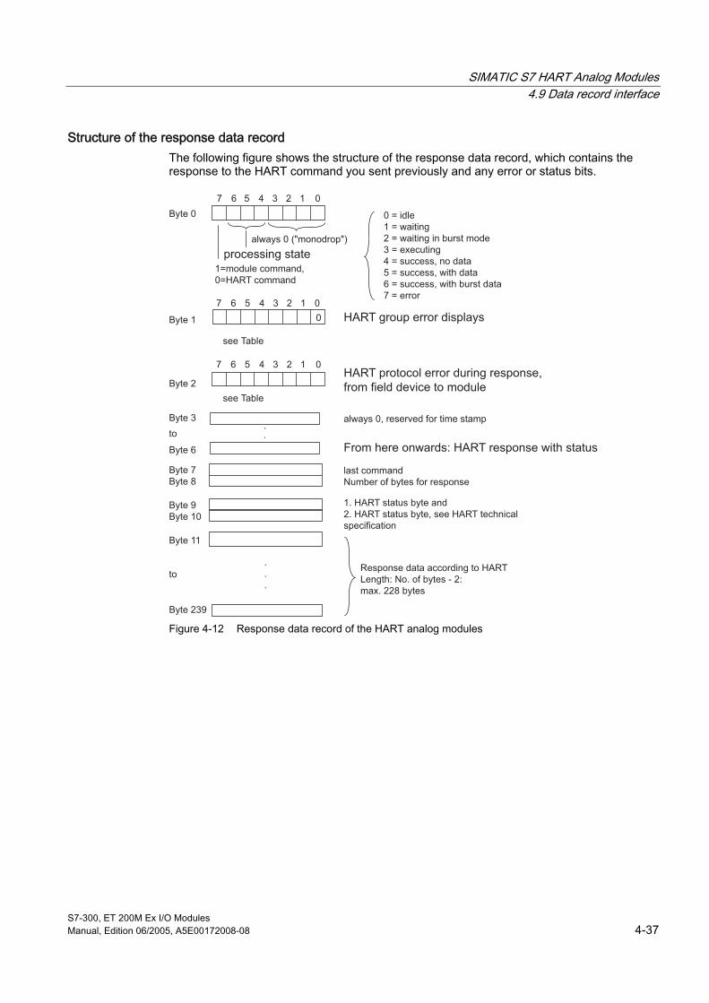
SIMATIC S7 HART Analog Modules 4.9 Data record interface
S7-300, ET 200M Ex I/O Modules Manual, Edition 06/2005, A5E00172008-08 4-37
Structure of the response data record The following figure shows the structure of the response data record, which contains the response to the HART command you sent previously and any error or status bits.
Byte 0
Byte 11
Byte 239
7 6 05 4 3 2 1
Byte 7Byte 8
0
7 6 05 4 3 2 1
Byte 2
7 6 05 4 3 2 1
.
.
.
Byte 1
Byte 3
Byte 6
Byte 9Byte 10
.
.
0 = idle1 = waiting2 = waiting in burst mode3 = executing4 = success, no data5 = success, with data6 = success, with burst data7 = error
HART group error displays
always 0 ("monodrop")
see Table
see Table
to
to
processing state1=module command,0=HART command
always 0, reserved for time stamp
From here onwards: HART response with status
last commandNumber of bytes for response
1. HART status byte and2. HART status byte, see HART technical specification
Response data according to HARTLength: No. of bytes - 2:max. 228 bytes
HART protocol error during response,from field device to module
Figure 4-12 Response data record of the HART analog modules

SIMATIC S7 HART Analog Modules 4.9 Data record interface
S7-300, ET 200M Ex I/O Modules 4-38 Manual, Edition 06/2005, A5E00172008-08
Evaluating the response data When you have an up-to-date response data record, you can check the following:
• You can use the "last command" byte to check that the response belongs to the command sent.
• You can evaluate the "Group error bits" (see following table) to locate individual errors.
• You can obtain more information from "HART protocol errors during response" (see following table) and both HART status bytes.
• In the group error bytes the corresponding bits will be set to "1".
Table 4-13 HART group error displays
Bit No. HART group error display Meaning 0 always 0 not used 1 command rejected Used in the following cases:
For a module command which does not exist. If you try to activate the burst mode when it is already activated. If you try to deactivate the burst mode when it was activated by another client. If you try to change the polling address of the HART field device.
2 further status information available. Corresponds to bit 4 in the 2nd HART status byte. You can obtain further status information with the HART command 48.
3 HART device status--> "Modification of parameters" entry in diagnostic data, data record 1
The field device transmits its device state. This information is found in the 2nd HART status byte which is accepted unchanged.
4 HART command status The field device transmits displays on the receipt of the command. Information on this can be found in the 1st HART status byte.
5 Error during HART communication--> "HART group error" entry in diagnostic data, data record 1
The field device has detected a communication error while receiving the command. Information on the error can be found in the 1st HART status byte which is accepted unchanged.
6 HART protocol error during response--> "HART group error" entry in diagnostic data, data record 1
Error during HART communication between field device and module, i.e. the response was incorrectly received. Information on the cause of the error can be found in the next byte. See following table.
7 Wire break--> parallel entry "Wire break" in diagnostic data, data record 1
The connection to the measuring transducer or the signal control element has been broken.

SIMATIC S7 HART Analog Modules 4.9 Data record interface
S7-300, ET 200M Ex I/O Modules Manual, Edition 06/2005, A5E00172008-08 4-39
Table 4-14 HART protocol error during response from field device to module
Bit No. HART protocol error in byte 2 Meaning 0 bad frame timing Waiting time elapsed without response being
received from field device. 1 always 0 not used 2 bad character transmission timing The pause between two bytes was not observed. 3 checksum error in response The checksum calculated does not match the
checksum transmitted. 4 Response frame error Error receiving HART signal (in UART) 5 Response overrun error Error receiving HART signal (in UART) 6 Response parity error Error receiving HART signal (in UART) 7 HART access not possible The connection to the field device is constantly
busy. This error is registered if the transmission time exceeds 10 seconds.
4.9.5 Additional diagnostic data records
Additional diagnostic data The additional diagnostic data provide information on the state of the HART communication following the last command.
• Additional diagnostic data record 128 for channel 0, 129 for channel 1
• Additional diagnostic data record 130 for channels 0 and 1: When the module starts up the recognized connected HART field devices and their identifiers ("tags") are entered here.
• Additional diagnostic data records 131 for channel 0 and 151 for channel 1 with the data for the identifiers found in the additional diagnostic data record 130.
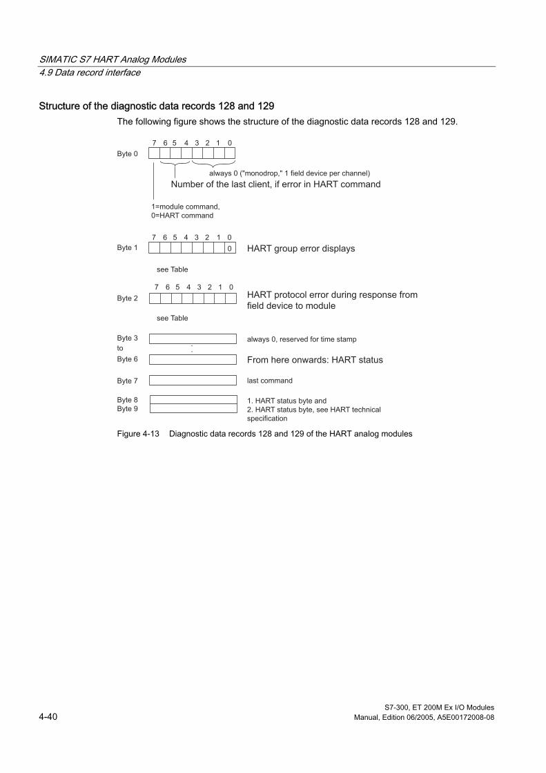
SIMATIC S7 HART Analog Modules 4.9 Data record interface
S7-300, ET 200M Ex I/O Modules 4-40 Manual, Edition 06/2005, A5E00172008-08
Structure of the diagnostic data records 128 and 129 The following figure shows the structure of the diagnostic data records 128 and 129.
Byte 0
7 6 05 4 3 2 1
Byte 7
0
7 6 05 4 3 2 1
Byte 2
7 6 05 4 3 2 1
Byte 1
Byte 3
Byte 6
Byte 8Byte 9
.
.
HART group error displays
always 0, reserved for time stamp
always 0 ("monodrop," 1 field device per channel)
1=module command,0=HART command
Number of the last client, if error in HART command
see Table
see Table
to
From here onwards: HART status
last command
1. HART status byte and2. HART status byte, see HART technical specification
HART protocol error during response from field device to module
Figure 4-13 Diagnostic data records 128 and 129 of the HART analog modules

SIMATIC S7 HART Analog Modules 4.9 Data record interface
S7-300, ET 200M Ex I/O Modules Manual, Edition 06/2005, A5E00172008-08 4-41
Structure of the diagnostic data record 130 The following diagram shows the structure of the diagnostic data record 130, which you can request to implement automatic recognition of the connected HART measuring transducer or the HART signal control elements.
715 08
715 08
Bits 1 to 15 = 0
Bit no.
Bit no.
1 = HART field device found0 = no HART field device connected
1 = HART identification found 0 = no HART identification found
Bits 1 to 15 = 0
Bytes 3/2for channel 0andBytes 7/6for channel 1
Bytes 1/0for channel 0andBytes 5/4for channel 1
Figure 4-14 Diagnostic data record 130 of the HART analog modules
Structure of the diagnostic data records 131 and 151 These contain the data corresponding to the identifiers marked in data record 130: The address of the HART field device which was found and the HART identification with tags or identifiers for a signal control element. The structure is illustrated in the following diagram.
• Data record 131 for channel 0 (length: 38 bytes)
• Data record 151 for channel 1 (length: 38 bytes)
Byte 0
Byte 1
Byte 16
7 6 05 4 3 2 1
.
.
Byte 17
Byte 37
.
.Measuring point identifier (“tag”):Response data to the HART command 13
No. of bytes for the response data to the HART command 0
HART identification:Response data to the HART command 0(”long-frame" address: bytes 1,2 and 9-11 )
Figure 4-15 Diagnostic data records 131 and 151 of the HART analog module

SIMATIC S7 HART Analog Modules 4.9 Data record interface
S7-300, ET 200M Ex I/O Modules 4-42 Manual, Edition 06/2005, A5E00172008-08
4.9.6 Additional parameter data records
Structure of the parameter data records 128 and 129 The following diagram shows the structure of the additional parameter data records 128 for channel 0 and 129 for channel 1. The settings affect the assigned channel:
Byte 0
7 6 05 4 3 2 1
Byte 1
Byte 2
Number of repeated attempts with HART communication
Wire break filter time,unit: 0.25 seconds (only AI HART)
Time required to update HART variables in user data area, see Figure 4-20unit: 0.25 sec.
Figure 4-16 Parameter data records 128 and 129 of the HART analog modules
Notes on the additional parameters The additional parameters comprise parameters which you do not normally need to change, as they have already been set to an optimized value: The following table provides explanations of the parameters and the default values.
Table 4-15 Additional parameters of the HART analog modules
Parameter Explanation Value range and default setting Repeated attempts If the HART analog modules transmit a
command to the field device and the connection is busy, the set number of repeated attempts is started.
Value range: Default setting: No repeat attempts:
0 to 127 3 0
Wire break filter time 1 A wire break is only signaled if it occurs for longer than the set filter time.
Value range: Default setting: no filter time:
0 to 20 3 Ø 0.75 sec. 0
Update time The HART modules send the HART command 1 automatically, to read the present value of the primary variable.
Value range: Default setting: no filter time:
0 to 255 12 Ø 3 sec. 0
1 As some measuring transducers take longer than others to start up, you may find that several diagnostic interrupts are triggered during start-up. The wire break filter time was introduced to avoid this problem.
Default parameter assignment for DP master class 2 When the HART analog modules have no parameters, for example, after a power failure, they can obtain default parameters from PROFIBUS-DP master class 2 while the programmable logic controller is deactivated. This is carried out with the aid of parameter data record No. 250 which consists of one byte with the value unequal 0. However, the assignment of default parameters can only be initiated when the module is in an unparameterized state. You can determine the state of the module by reading the diagnostic data record.

SIMATIC S7 HART Analog Modules 4.9 Data record interface
S7-300, ET 200M Ex I/O Modules Manual, Edition 06/2005, A5E00172008-08 4-43
4.9.7 User data interface - input area (read)
Structure of the user data The following figure shows the structure of the user data area for the HART analog input module. The data for the user data area can be read in the desired format using "Read peripheral data" (for example, L PIW 256) and evaluated in your user program.
Byte 4
Byte 5
Byte 6
Byte 7
Byte 0
Byte 1
Byte 9
Byte 2
Byte 3
Byte 8
0
Byte 12
Byte 13
Byte 14
Byte 15
Byte 10Byte 11
7 6 05 4 3 2 1
Channel 0Analog input value (with AI HART)Readback value (with AO HART)
Channel 1Analog input value (with AI HART)Readback value (with AO HART)
Main process quantity (primary variable):Process value as floating point - as specified in HART for channel 0
Data ready bit = 1 indicates that there are unread response data in the transfer area of the client.
HART code for the physical size of the HART variables for channel 0
Data for channel 1: structure analog to channel 0, bytes 4 - 9
Bit No. Client no.
Value in S7 format
Value in S7 format
Value in IEEE754 floating-point format
Figure 4-17 Input user data area of the HART analog modules

SIMATIC S7 HART Analog Modules 4.9 Data record interface
S7-300, ET 200M Ex I/O Modules 4-44 Manual, Edition 06/2005, A5E00172008-08
4.9.8 Output Area (write)
Structure of the user data The following diagram shows the structure of the user data area for the HART analog output modules. The data for the user data area can be read in the desired format using "Write peripheral data" (for example, L POW 256) and evaluated in your user program.
Byte 4
Byte 0
Byte 1
Byte 2
Byte 3
Byte 15
0
0
.
.
.
.
.
.
Channel 0Analog output value(only with AO HART)
Channel 1Analog output value(only with AO HART)
reserved
Value in S7 format
Value in S7 format
Figure 4-18 User data area of the HART analog output module

S7-300, ET 200M Ex I/O Modules Manual, Edition 06/2005, A5E00172008-08 A-1
A Certificates AA.1 A.1 Overview of diagnostic functions
Overview On the following pages you will find copies of the certificates of conformity.
Module Order Number You Will Find
SM 321; DI 4 x NAMUR 6ES7321-7RD00-0AB0 EU Declaration of Conformity SM 321; DI 4 x NAMUR 6ES7321-7RD00-0AB0 EU Declaration of Conformity SM 322; DO 4 x 24 V/10 mA 6ES7322-5SD00-0AB0 EU Declaration of Conformity SM 322; DO 4 x 24 V/10 mA 6ES7322-5SD00-0AB0 EU Declaration of Conformity SM 322; DO 4x15 V/20 mA 6ES7322-5SD00-0AB0 EU Declaration of Conformity SM 322; DO 4x15 V/20 mA 6ES7322-5SD00-0AB0 EU Declaration of Conformity AI 8 x TC / 4 x RTD 6ES7331-7SF00-0AB0 EU Declaration of Conformity AI 8 x TC / 4 x RTD 6ES7331-7SF00-0AB0 EU Declaration of Conformity SM331; AI 4x0/4...20 mA 6ES7331-7RD00-0AB0 EU Declaration of Conformity SM331; AI 4x0/4...20 mA 6ES7331-7RD00-0AB0 EU Declaration of Conformity SM331; AI 4x0/4...20 mA 6ES7332-5SD00-0AB0 EU Declaration of Conformity SM331; AI 4x0/4...20 mA 6ES7332-5SD00-0AB0 EU Declaration of Conformity SM331; AI 2 x 0/4...20 mA HART 6ES7331-7TB00-0AB0 EU Declaration of Conformity SM331; AI 2 x 0/4...20 mA HART 6ES7331-7TB00-0AB0 1. Amendment SM331; AI 2 x 0/4...20 mA HART 6ES7331-7TB00-0AB0 2. Amendment SM331; AI 2 x 0/4...20 mA HART 6ES7331-7TB00-0AB0 3. Amendment SM331; AI 2 x 0/4...20 mA HART 6ES7331-7TB00-0AB0 4. Amendment SM331; AI 2 x 0/4...20 mA HART 6ES7331-7TB00-0AB0 5. Amendment SM331; AI 2 x 0/4...20 mA HART 6ES7331-7TB00-0AB0 EU Declaration of Conformity SM332; AO 2 x 0/4...20 mA HART 6ES7332-5TB00-0AB0 EU Declaration of Conformity SM332; AO 2 x 0/4...20 mA HART 6ES7332-5TB00-0AB0 1. Amendment SM332; AO 2 x 0/4...20 mA HART 6ES7332-5TB00-0AB0 EU Declaration of Conformity

Certificates A.2 Certificate of Conformity for Digital Input DI 4 x NAMUR
S7-300, ET 200M Ex I/O Modules A-2 Manual, Edition 06/2005, A5E00172008-08
A.2 A.2 Certificate of Conformity for Digital Input DI 4 x NAMUR
A.2.1 EU Declaration of Conformity
Certificates

Certificates A.2 Certificate of Conformity for Digital Input DI 4 x NAMUR
S7-300, ET 200M Ex I/O Modules Manual, Edition 06/2005, A5E00172008-08 A-3
Appendix

Certificates A.2 Certificate of Conformity for Digital Input DI 4 x NAMUR
S7-300, ET 200M Ex I/O Modules A-4 Manual, Edition 06/2005, A5E00172008-08
Appendix

Certificates A.2 Certificate of Conformity for Digital Input DI 4 x NAMUR
S7-300, ET 200M Ex I/O Modules Manual, Edition 06/2005, A5E00172008-08 A-5
A.2.2 EU Declaration of Conformity for Digital Input DI 4 x NAMUR
Declaration

Certificates A.3 Certificates of Conformity for Digital Output DO 4 x 24V/10 mA
S7-300, ET 200M Ex I/O Modules A-6 Manual, Edition 06/2005, A5E00172008-08
A.3 A.3 Certificates of Conformity for Digital Output DO 4 x 24V/10 mA
A.3.1 EU Declaration of Conformity
Certificates

Certificates A.3 Certificates of Conformity for Digital Output DO 4 x 24V/10 mA
S7-300, ET 200M Ex I/O Modules Manual, Edition 06/2005, A5E00172008-08 A-7
Appendix

Certificates A.3 Certificates of Conformity for Digital Output DO 4 x 24V/10 mA
S7-300, ET 200M Ex I/O Modules A-8 Manual, Edition 06/2005, A5E00172008-08
Appendix

Certificates A.3 Certificates of Conformity for Digital Output DO 4 x 24V/10 mA
S7-300, ET 200M Ex I/O Modules Manual, Edition 06/2005, A5E00172008-08 A-9
A.3.2 EU Declaration of Conformity for Digital Output DO 4 x 24V/10 mA
Declaration

Certificates A.4 Certificates of Conformity for Digital Output DO 4 x 15V/20 mA
S7-300, ET 200M Ex I/O Modules A-10 Manual, Edition 06/2005, A5E00172008-08
A.4 A.4 Certificates of Conformity for Digital Output DO 4 x 15V/20 mA
A.4.1 EU Declaration of Conformity
Certificates

Certificates A.4 Certificates of Conformity for Digital Output DO 4 x 15V/20 mA
S7-300, ET 200M Ex I/O Modules Manual, Edition 06/2005, A5E00172008-08 A-11
Appendix
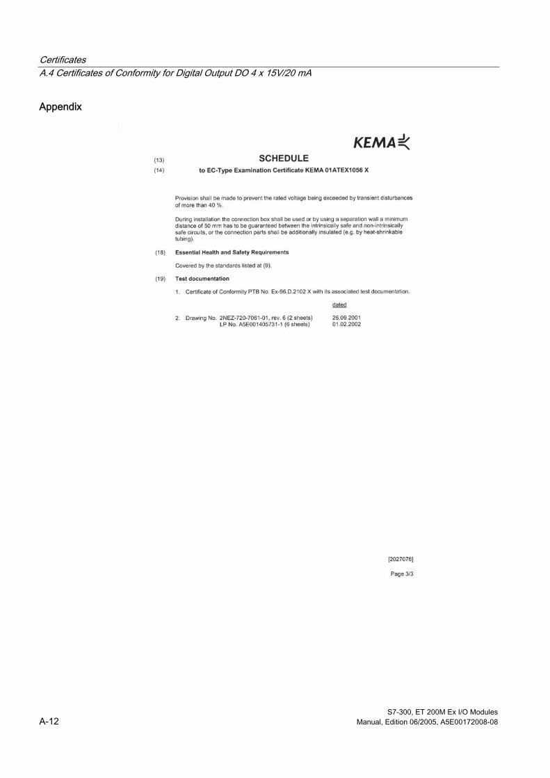
Certificates A.4 Certificates of Conformity for Digital Output DO 4 x 15V/20 mA
S7-300, ET 200M Ex I/O Modules A-12 Manual, Edition 06/2005, A5E00172008-08
Appendix

Certificates A.4 Certificates of Conformity for Digital Output DO 4 x 15V/20 mA
S7-300, ET 200M Ex I/O Modules Manual, Edition 06/2005, A5E00172008-08 A-13
A.4.2 EU Declaration of Conformity for Digital Output DO 4 x 15V/20 mA
Declaration

Certificates A.5 Certificates of Conformity for Analog Input AI 8 x TC/4 x RTD
S7-300, ET 200M Ex I/O Modules A-14 Manual, Edition 06/2005, A5E00172008-08
A.5 A.5 Certificates of Conformity for Analog Input AI 8 x TC/4 x RTD
A.5.1 EU Declaration of Conformity
Certificates

Certificates A.5 Certificates of Conformity for Analog Input AI 8 x TC/4 x RTD
S7-300, ET 200M Ex I/O Modules Manual, Edition 06/2005, A5E00172008-08 A-15
Appendix

Certificates A.5 Certificates of Conformity for Analog Input AI 8 x TC/4 x RTD
S7-300, ET 200M Ex I/O Modules A-16 Manual, Edition 06/2005, A5E00172008-08
Appendix

Certificates A.5 Certificates of Conformity for Analog Input AI 8 x TC/4 x RTD
S7-300, ET 200M Ex I/O Modules Manual, Edition 06/2005, A5E00172008-08 A-17
A.5.2 EU Declaration of Conformity for Analog Input AI 8 x TC/4 x RTD
Declaration

Certificates A.6 Certificates of Conformity for Analog Input AI 4 x 0/4...20 mA
S7-300, ET 200M Ex I/O Modules A-18 Manual, Edition 06/2005, A5E00172008-08
A.6 A.6 Certificates of Conformity for Analog Input AI 4 x 0/4...20 mA
A.6.1 EU Declaration of Conformity
Appendix
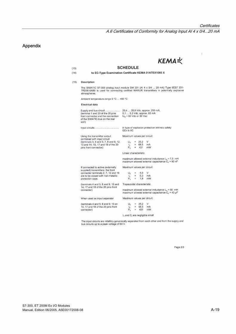
Certificates A.6 Certificates of Conformity for Analog Input AI 4 x 0/4...20 mA
S7-300, ET 200M Ex I/O Modules Manual, Edition 06/2005, A5E00172008-08 A-19
Appendix

Certificates A.6 Certificates of Conformity for Analog Input AI 4 x 0/4...20 mA
S7-300, ET 200M Ex I/O Modules A-20 Manual, Edition 06/2005, A5E00172008-08
Appendix

Certificates A.6 Certificates of Conformity for Analog Input AI 4 x 0/4...20 mA
S7-300, ET 200M Ex I/O Modules Manual, Edition 06/2005, A5E00172008-08 A-21
A.6.2 EU Declaration of Conformity for Analog Input AI 4 x 0/4...20 mA
Declaration

Certificates A.7 Certificates of Conformity for Analog Output AO 4 x 0/4...20 mA
S7-300, ET 200M Ex I/O Modules A-22 Manual, Edition 06/2005, A5E00172008-08
A.7 A.7 Certificates of Conformity for Analog Output AO 4 x 0/4...20 mA
A.7.1 EU Declaration of Conformity
Certificates
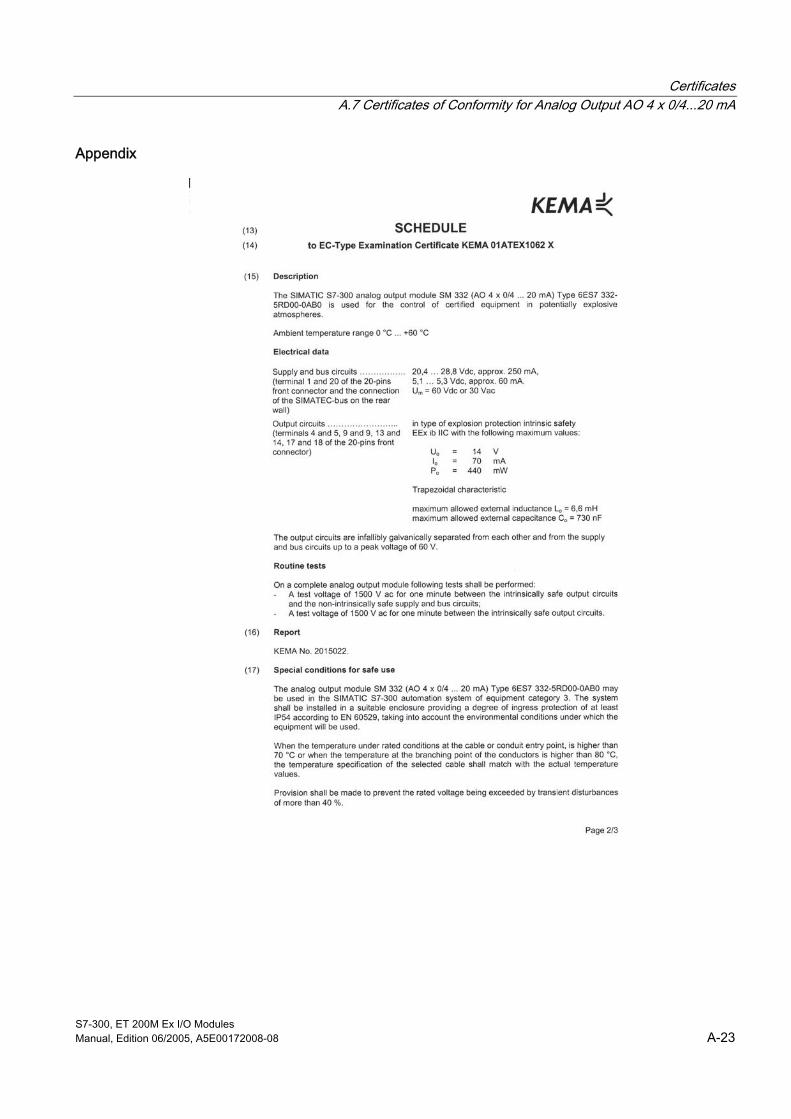
Certificates A.7 Certificates of Conformity for Analog Output AO 4 x 0/4...20 mA
S7-300, ET 200M Ex I/O Modules Manual, Edition 06/2005, A5E00172008-08 A-23
Appendix

Certificates A.7 Certificates of Conformity for Analog Output AO 4 x 0/4...20 mA
S7-300, ET 200M Ex I/O Modules A-24 Manual, Edition 06/2005, A5E00172008-08
Appendix

Certificates A.7 Certificates of Conformity for Analog Output AO 4 x 0/4...20 mA
S7-300, ET 200M Ex I/O Modules Manual, Edition 06/2005, A5E00172008-08 A-25
A.7.2 EU Declaration of Conformity for Analog Output AO 4 x 0/4...20 mA
Declaration

Certificates A.8 Certificates of Conformity for Analog Input AI 2 x 0/4...20 mA HART
S7-300, ET 200M Ex I/O Modules A-26 Manual, Edition 06/2005, A5E00172008-08
A.8 A.8 Certificates of Conformity for Analog Input AI 2 x 0/4...20 mA HART
A.8.1 EU Declaration of Conformity
Certificates

Certificates A.8 Certificates of Conformity for Analog Input AI 2 x 0/4...20 mA HART
S7-300, ET 200M Ex I/O Modules Manual, Edition 06/2005, A5E00172008-08 A-27
Appendix
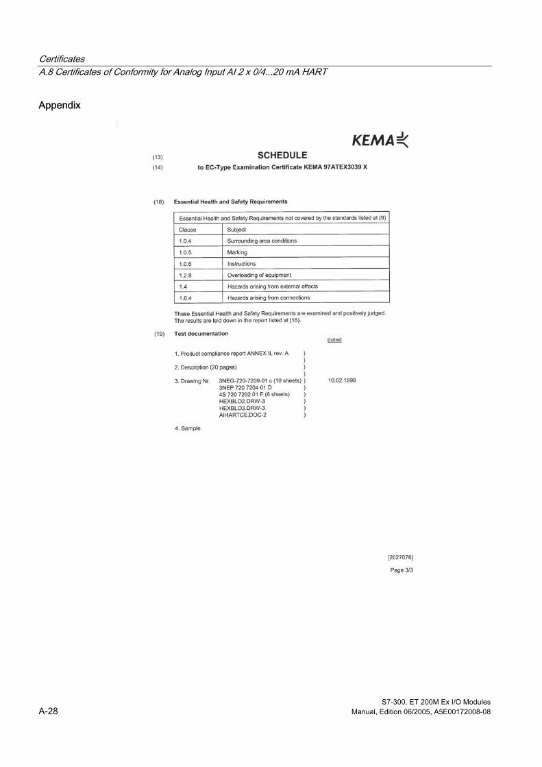
Certificates A.8 Certificates of Conformity for Analog Input AI 2 x 0/4...20 mA HART
S7-300, ET 200M Ex I/O Modules A-28 Manual, Edition 06/2005, A5E00172008-08
Appendix

Certificates A.8 Certificates of Conformity for Analog Input AI 2 x 0/4...20 mA HART
S7-300, ET 200M Ex I/O Modules Manual, Edition 06/2005, A5E00172008-08 A-29
A.8.2 1. Amendment to analog input AI 2 x 0/4...20 mA HART
Amendment

Certificates A.8 Certificates of Conformity for Analog Input AI 2 x 0/4...20 mA HART
S7-300, ET 200M Ex I/O Modules A-30 Manual, Edition 06/2005, A5E00172008-08
A.8.3 2. Amendment to analog input AI 2 x 0/4...20 mA HART
Amendment
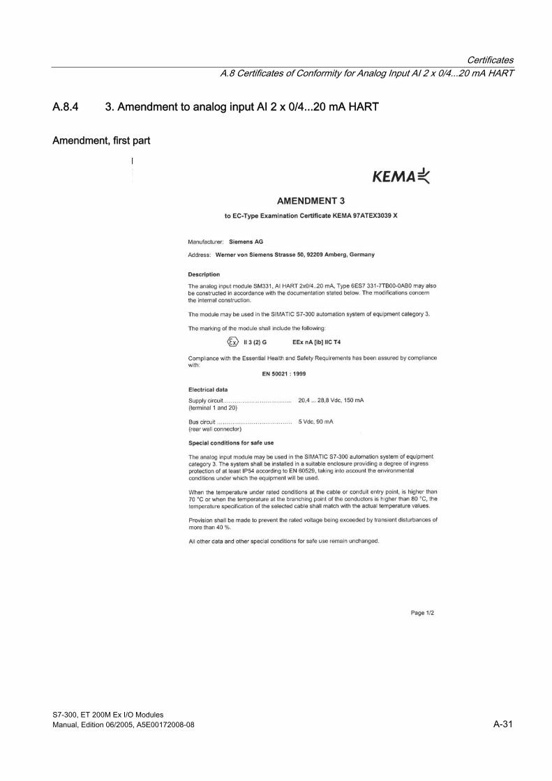
Certificates A.8 Certificates of Conformity for Analog Input AI 2 x 0/4...20 mA HART
S7-300, ET 200M Ex I/O Modules Manual, Edition 06/2005, A5E00172008-08 A-31
A.8.4 3. Amendment to analog input AI 2 x 0/4...20 mA HART
Amendment, first part

Certificates A.8 Certificates of Conformity for Analog Input AI 2 x 0/4...20 mA HART
S7-300, ET 200M Ex I/O Modules A-32 Manual, Edition 06/2005, A5E00172008-08
Amendment, second part

Certificates A.8 Certificates of Conformity for Analog Input AI 2 x 0/4...20 mA HART
S7-300, ET 200M Ex I/O Modules Manual, Edition 06/2005, A5E00172008-08 A-33
A.8.5 4. Amendment to analog input AI 2 x 0/4...20 mA HART
Amendment

Certificates A.8 Certificates of Conformity for Analog Input AI 2 x 0/4...20 mA HART
S7-300, ET 200M Ex I/O Modules A-34 Manual, Edition 06/2005, A5E00172008-08
A.8.6 5. Amendment to analog input AI 2 x 0/4...20 mA HART
Amendment
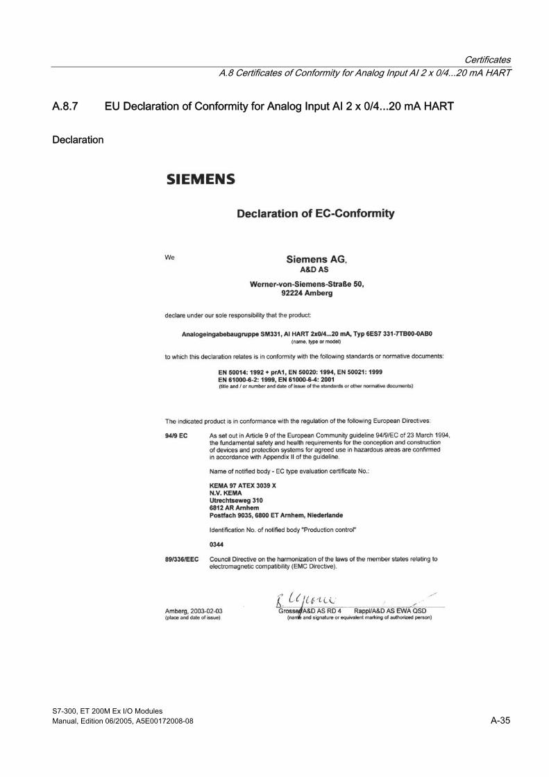
Certificates A.8 Certificates of Conformity for Analog Input AI 2 x 0/4...20 mA HART
S7-300, ET 200M Ex I/O Modules Manual, Edition 06/2005, A5E00172008-08 A-35
A.8.7 EU Declaration of Conformity for Analog Input AI 2 x 0/4...20 mA HART
Declaration

Certificates A.9 Certificates of Conformity for Analog Output AO 2 x 0/4...20 mA HART
S7-300, ET 200M Ex I/O Modules A-36 Manual, Edition 06/2005, A5E00172008-08
A.9 A.9 Certificates of Conformity for Analog Output AO 2 x 0/4...20 mA HART
A.9.1 EU Declaration of Conformity
Certificates

Certificates A.9 Certificates of Conformity for Analog Output AO 2 x 0/4...20 mA HART
S7-300, ET 200M Ex I/O Modules Manual, Edition 06/2005, A5E00172008-08 A-37
Appendix

Certificates A.9 Certificates of Conformity for Analog Output AO 2 x 0/4...20 mA HART
S7-300, ET 200M Ex I/O Modules A-38 Manual, Edition 06/2005, A5E00172008-08
Appendix

Certificates A.9 Certificates of Conformity for Analog Output AO 2 x 0/4...20 mA HART
S7-300, ET 200M Ex I/O Modules Manual, Edition 06/2005, A5E00172008-08 A-39
A.9.2 1. Amendment to analog output AO 2 x 0/4...20 mA HART
Amendment
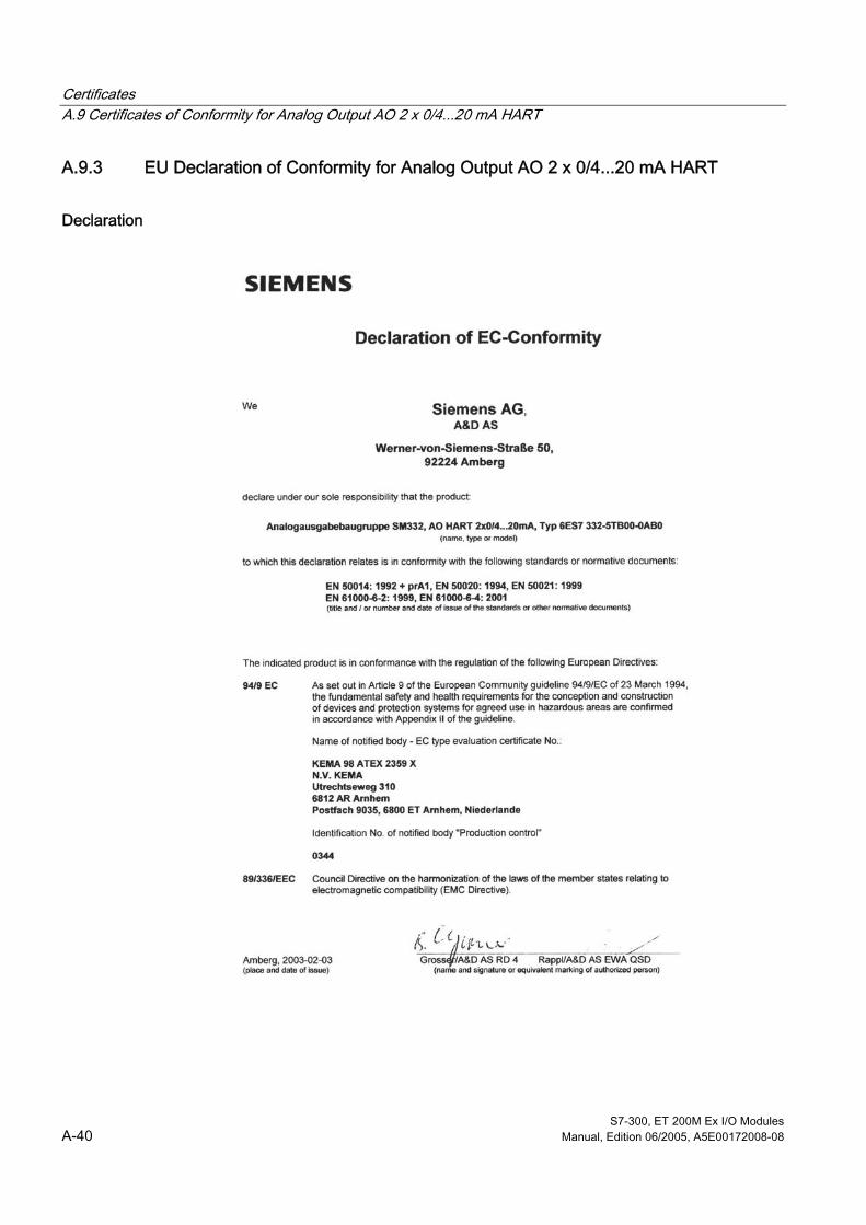
Certificates A.9 Certificates of Conformity for Analog Output AO 2 x 0/4...20 mA HART
S7-300, ET 200M Ex I/O Modules A-40 Manual, Edition 06/2005, A5E00172008-08
A.9.3 EU Declaration of Conformity for Analog Output AO 2 x 0/4...20 mA HART
Declaration

S7-300, ET 200M Ex I/O Modules Manual, Edition 06/2005, A5E00172008-08 B-1
B Standards and licenses BB.1 B.1 Standards and licenses
CE certification
0344
The S7-300/ET 200M programmable controller meets the requirements and protection objectives of the following EU directives and complies with the harmonized European standards (EN) that have been published for programmable controllers in the Official Journal of the European Communities:
• 73/23/EEC on "electronic equipment for use within certain voltage ranges" (low voltage directive)
• 89/336/EEC on "electromagnetic compatibility" (EMC directive)
• 94/9/EC on "equipment and protective systems for use in potentially explosive atmospheres" (explosion protection directive)
The EU declarations of conformity are available for the respective authorities at the following address:
Siemens Aktiengesellschaft Bereich Automatisierungs- und Antriebstechnik A&D AS RD4 Postfach 1963 D-92209 Amberg

Certificates B.1 Standards and licenses
S7-300, ET 200M Ex I/O Modules B-2 Manual, Edition 06/2005, A5E00172008-08
Safety standards used The following safety standards apply to all EX modules:
• EN 50014 (1977 + A1 .. A5):
Electrical equipment for hazardous locations: General specifications.
• EN 50020 (1977 + A1.. A5):
Electrical equipment for hazardous locations: Intrinsic safety "i".
• DIN EN 61010 (part 1 v. 3/94):
Safety requirements for electrical measuring, control and laboratory equipment.
• DIN EN 61131 (part 2 v. 5/95):
Programmable logic controllers, operational equipment requirements and testing.
• DIN EN 60204 (part 1 v. 6/93):
Electrical equipment of machines: General requirements.
In the course of harmonization of the standards EN 50014 .. EN 50020 the designations of safety characteristic values have been adapted. The most important characteristic data for the relevant operational equipment are assigned as follows:
Uo, Umax, Ua → Uo Maximum output voltage Io, Ia, Ik → Io Maximum output current Um → Um Maximum r.m.s. power-frequency voltage or maximum
direct voltage Co, Ca → Co Maximum external capacitance Lo, La → Lo Maximum external inductance P, Pmax → Po Maximum output power C, Ci → Ci Maximum internal capacitance L, Li → Li Maximum internal inductance
HAZ. LOC.
Underwriters Laboratories Inc. in accordance with • UL 508 (Industrial Control Equipment) • CSA C22.2 No. 142 (Process Control Equipment) • UL 1604 (Hazardous Location) • CSA-213 (Hazardous Location)
APPROVED for use in Class I, Division 2, Group A, B, C, D T4; Class I, Zone 2, Group IIC T4

Certificates B.1 Standards and licenses
S7-300, ET 200M Ex I/O Modules Manual, Edition 06/2005, A5E00172008-08 B-3
FM license
Factory Mutual Research (FM) in accordance with Approval Standard Class Number 3611, 3600, 3810 APPROVED for use in Class I, Division 2, Group A, B, C, D T4; Class I, Zone 2, Group IIC T4
Identification code for Australia
The S7-300/ET 200M programmable controller meets the requirements of the AS/NZS 2064 (Class A) standard.
IEC 61131 The S7-300/ET 200M programmable controller meets the requirements and criteria of the IEC 61131-2 standard (programmable controllers, Part 2: requirements for equipment and tests).
Marine approval Classification authorities:
• ABS (American Bureau of Shipping)
• BV (Bureau Veritas)
• DNV (Det Norske Veritas)
• GL (Germanischer Lloyd)
• LRS (Lloyds Register of Shipping)
• Class NK (Nippon Kaiji Kyokai)
Industrial use SIMATIC products are designed for industrial use.
Table B-1 Industrial use
Scope of application Requirement Emitted interference Interference immunity Industry EN 61000-6-4: 2001 EN 61000-6-2: 2001

Certificates B.1 Standards and licenses
S7-300, ET 200M Ex I/O Modules B-4 Manual, Edition 06/2005, A5E00172008-08
Use in residential areas If you use the S7-300/ET 200M in residential areas, you must ensure that the radio interference emissions comply with limit value class B in accordance with EN 55011.
The following measures are recommended to ensure the interference complies with limit value class B:
• Install S7-300/ET 200M in grounded switching cabinets/boxes
• Install filters in supply lines
Warning
Risk of injury and damage to property
There is a risk of injury and damage to property in hazardous areas if you remove plug connectors while a S7-300/ET 200M is in operation.
Before you remove plug connectors in hazardous areas, always deenergize the S7-300/ET 200M.
S7-300, ET 200M Ex I/O Modules Manual, Edition 06/2005, A5E00172008-08 Glossary-1
Glossary
AS --> Automation system
Automation system An automation system is a programmable controller comprising of at least one --> CPU, various input and output modules as well as operating and monitoring devices.
Backplane bus The backplane bus is a serial data bus through which the modules communicate with one another and through which they are supplied with the necessary voltage. The connection between the modules is created by the bus connector.
The --> I/O bus is a component of the backplane bus.
Backplane bus active Backplane bus of the distributed I/O system --> ET 200M, which is made of active bus modules. This is the prerequisite for a configuration with which "inserting and removing" is permitted during operation.
Baud rate The baud rate is the speed of the data transmission and indicates the number of transferred bits per second (Baud rate = bit rate).
With → ET 200 baud rates of 9.6 kBaud up to 12 MBaud are possible.
Bus mutual transmission path with which all the users are connected, and which possess the two defined ends.
With → ET 200 the bus is a two-wire line or a fiber-optic cable.
Bus user Device that sends, receives or can amplify data via the --> bus, active star coupler.

Glossary
S7-300, ET 200M Ex I/O Modules Glossary-2 Manual, Edition 06/2005, A5E00172008-08
CELENEC European Committee for Electrical Standards
Client A client can request a service from a --> server. A client can, for example, be a program, a central module (CPU) or a station (e.g. PC). The data exchange between the client and server can, for example, take place via --> PROFIBUS-DP in the --> master slave procedure. With several clients the coordination of the data exchange between the client and server can also take place, e.g. by means of separate transmission areas for each client.
Configuration Assigning modules to subracks / slots and addresses. A distinction is made between actual configuration (= actual inserted modules) and calculated configuration. You stipulate the calculated configuration with the help of STEP 7, COM PROFIBUS. In this way, upon start-up the operating system can detect any incorrect insertions.
Configuring (initialize, assign parameters to) Included in parameterization is the setting of the behavior of a module or a --> field device by parameters.
CPU Central Processing Unit = central module of the S7 programmable controller with a controller, arithmetic unit, memory, operating system and interface for programming devices.
Diagnostic interrupt Diagnostic-capable modules report detected system errors via diagnostic interrupts to the central --> CPU.
In SIMATIC S7/M7: With the detection or disappearance of an error (e.g. wire break), the module triggers a diagnostics interrupt provided this interrupt is enabled. The --> CPU interrupts the processing of the user program or low-priority classes and processes the diagnostic interrupt module (OB82).
In SIMATIC S5: The diagnostic interrupt is reproduced within the device-related --> diagnostics. It can detect errors, like for example, wire breaks, by means of the cyclic querying of the diagnostics bit in the device-related diagnostics.
Diagnostics Diagnostics is the detection, localization, classification, display, further evaluation of errors, faults and messages.
Diagnostics offers monitoring functions that automatically run while the system is in operation. This hence increases the availability of systems by reducing the installation and down times.

Glossary
S7-300, ET 200M Ex I/O Modules Manual, Edition 06/2005, A5E00172008-08 Glossary-3
Diagnostics buffer The diagnostics buffer is a buffered memory area in the CPU in which diagnostics events can be stored in the order of occurrence.
In the area of ground connectors, the ground span can have any potential starting from zero. The term "reference ground" is often used for this situation.
Distributed I/Os are input / output units that are not used in the central device, but decentrally at a greater distance from the --> CPU, e.g.:
• ET 200M, ET 200B, ET 200C, ET 200U
• DP/AS-I Link
• S5-95U with PROFIBUS-DP slave interface
• further → DP slaves by Siemens or other manufacturers
The distributed I/Os are connected via --> PROFIBUS-DP with the --> DP master.
DP address: Each --> bus user must receive a DP address for the clear identification on the --> PROFIBUS-DP.
PC/PG or the ET 200 hand-helds have the DP address "0".
→ DP-Master and → DP slaves have a DP address from the range 1 to 125.
DP master A → master that behaves in accordance with the standard EN 50170, Volume 2, → PROFIBUS, is classed as a DP master.
DP slave A → slave, which is operated on the bus → PROFIBUS with the protocol → PROFIBUS-DP and that behaves in accordance with the standard EN 50170, Volume 2, → PROFIBUS, is a DP Slave.
DP standard is the bus protocol of the distributed I/O system ET 200 in accordance with the standard EN 50170 Volume 2, → PROFIBUS.
Dynamic parameters Dynamic parameters of modules can, by contrast to static parameters, be changed by the user program during operation.

Glossary
S7-300, ET 200M Ex I/O Modules Glossary-4 Manual, Edition 06/2005, A5E00172008-08
Error handling via OB If the operating system detects a specific error (e.g. →access fault with STEP 7), it calls up the respective --> organization block (error OB) for this case, in which the further behavior --> of the CPU can be established.
ET 200 The distributed I/O system ET 200 with the protocol --> PROFIBUS-DP is a --> bus for connecting distributed I/Os to a --> CPU or an equivalent --> DP-Master. ET 200 is characterized by fast --> reaction times, as only a few bytes are transmitted.
ET 200 is based on the standard EN 50170, Volume 2, --> PROFIBUS.
ET 200 works in accordance with the master slave principle. → DP-Masters can, for example, be the master connection IM 308-C or the CPU 315-2 DP.
→ DP slaves can be distributed I/Os ET 200B, ET 200C, ET 200M, ET 200U or DP slaves by Siemens or other manufacturers.
Fault indication The fault indication is one of the possible reactions of the operating system to a --> runtime error. The other reaction possibilities are: → fault reaction in the user program, STOP status → of the CPU or the IM 153-1.
Fault reaction Reaction to a runtime error. The operating system can react in the following ways: Put the programmable controller in the STOP state, call up a --> organization block, whereby the user can program a reaction, or display an error.
Field Either an area of a system outside of the control room, where measured values regarding communication can be gained or manipulated values sent to actuators.
Or part of a message, e.g. address field or command field, that is dedicated to a particular function. The dimensions or other regulations for the interpretation of each field are part of the protocol specification.
Field device A → transducer, that is located on the → field and exchanges communication data with the central system.
Field device, intelligent (smart device) A field device with more complex functionality, which includes a microprocessor and the functions of which can be set via a respective --> parameter assignment toll by the control room.

Glossary
S7-300, ET 200M Ex I/O Modules Manual, Edition 06/2005, A5E00172008-08 Glossary-5
FM Factory Mutual, USA Quality Assurance System
frequency shift keying (FSK) is a data modulation technique that is suitable for the data transport via normal lines. Two audio frequencies are used for this, in order to code the binary "0" and "1" in the frequency range 300 - 3000 Hz. With → HART protocol the FSK signal is transmitted via a current loop.
FSK frequency shift keying
Ground The conductive ground, the electric potential of which can be set at zero at every point.
In the area of ground connectors, the ground span can have any potential starting from zero. The term "reference ground" is often used for this situation.
One or more conductive parts that can have very good contact with the ground.
All the inactive parts of operational equipment that are linked to each other are all included as ground. Also in the event of a fault they do not adopt any dangerous contact voltage.
Hardware interrupt A hardware interrupt is triggered by interrupt-capable S7-300 modules on account of a specific event in the process. The hardware alarm is reported to the central --> CPU. In accordance with the priority of this interrupt, then the assigned organization block is edited.
In SIMATIC S7/M7: The range is defined by parameterization of an upper and a lower limit. If the process signal (e.g. temperature of an analog input module) is outside this range, the module triggers a hardware interrupt provided limit interrupt is enabled. The --> CPU interrupts the processing of the user program or low-priority classes and processes the diagnostic interrupt block (OB40).
In SIMATIC S5: The hardware interrupt is reproduced within the device-related --> diagnostics. It can detect hardware interrupts, like for example, exceeding the upper limit, by means of the cyclic querying of the diagnostics bit in the device-related diagnostics.
HART Highway Addressable Remote Transducer. HART is a registered trademark of the --> HART Communication Foundation.
HART analog modules Analog modules which, in addition to their analog value, can carry out --> HART communication. HART analog modules can be used as --> HART interfaces for HART field devices.

Glossary
S7-300, ET 200M Ex I/O Modules Glossary-6 Manual, Edition 06/2005, A5E00172008-08
HART commands The HART field device works as a slave and is controlled by the master by means of HART commands. The master sets the --> HART parameters or requests data in the form of --> HART responses.
HART communication Transmitting data between a master (e.g. HART analog module) and a slave (--> HART field device) via the --> HART protocol.
HART Communication Foundation The HART Communication Foundation (HCF) was founded in 1993 in order to market and further develop the HART protocol. The HCF is an establishment that is not focused on profits and it is financed by its members.
HART field device Intelligent field device that has a --> HART-compatible additional functionality, so that it understands the --> HART communication.
HART hand-held The HART hand-held includes the original parameter assignment tool by Fisher-Rosemount Ltd. for --> HART field devices, which is directly linked to its connections. The --> HART parameters are set using the HART hand-held.
HART interface Part of a system with which a --> HART field device can be connected. The HART interface represents the master for the field device. With reference to the system, the HART interface however is a slave that can supply the system via various masters. A master represents, e.g. the --> HART parameter assignment tool. The programmable controller is itself a different master.
HART parameter The HART parameters call the configurable features of --> HART field devices, which can be changed via the --> HART protocol. The setting takes place via a --> HART parameter assignment tool.
HART parameter assignment tool The HART parameter assignment tool is used to comfortably set the --> HART parameters. It can be a --> HART hand-held or a parameter assignment tool that is integrated in the system, e.g. SIMATIC SIPROM.
HART protocol The → HART protocol is the industry standard for expanded communication with --> HART field devices. It includes the --> HART commands and the --> HART responses.

Glossary
S7-300, ET 200M Ex I/O Modules Manual, Edition 06/2005, A5E00172008-08 Glossary-7
HART responses The HART field devices transmits data upon the request of the master. This data is measuring results or manipulated values or values from the --> HART parameters. A HART response always includes a status information, the --> HART status byte.
HART signal Analog signal on a current loop from 4 - 20 mA, where the aid of the --> FSK procedure, the sinus waves for the --> HART protocol, 1200 Hz for the binary "1" and 2200 Hz for the binary "0" can be modulated.
HART status byte The status information that consists of the 1st and 2nd status byte of the --> HART response and with which the HART field device offers information via the --> HART communication, the receipt of the --> HART command and the device status.
HART transfer area Area of data records that are established for writing HART commands and reading HART responses with the HART analog modules. The HART transfers area comprises data records. Each --> client is assigned its own range of data records, with which the --> server can exchange data with the client.
HCF --A HART Communication Foundation
I/O bus Component of the --> S7-300 backplane bus in the --> programmable controller system, optimized at the fast exchange of signals between the IM 153 and the signal modules. Via the I/O bus --> user data (e.g. digital input signals of a signal module) and system data (e.g. --> default parameter data records of a signal module) are transmitted.
Interrupt The operating system of the --> CPU recognizes 10 different priority classes that regulate the editing of the user program. Included in these priority classes are, for example, hardware interrupts. When an interrupt is triggered the operating system automatically calls up an assigned organization block in which the user can program the desired reaction.
isolated With isolated input/output modules the --> reference potentials of control and load circuits are metallically linked e.g. by optocouplers, relay contacts or conductors. Input/output circuits can be rooted.
KEMA Certification office for products

Glossary
S7-300, ET 200M Ex I/O Modules Glossary-8 Manual, Edition 06/2005, A5E00172008-08
Load mains device Power supply to feed the signal and function modules and the process interface systems connected to it.
Master class 1 --> Master that carries out the user data traffic and with which the configuration and diagnostics of the distributed I/Os takes place.
Master class 2 --> Master for controlling / installing and configuration tasks, e.g. configuring and diagnostics of the field devices that are connected to the distribution I/Os.
Master slave procedure Bus access procedure whereby in each case only one user is the --> DP-Master and all other users are --> DP slaves.
Masters can, if they possess the token, send data to other users and request data from other users (= active user).
→ DP-Masters can, for example, be the master connection IM 308-C or the CPU 315-2 DP.
modem A modem (modulator / demodulator) is a device that converts binary digital signals into --> FSK signals and vice-versa. A modem doesn´t code data, it offers a conversion of the physical form of the signals.
Module parameters Module parameters are values using which the behavior of the module can be modified. We distinguish between static and dynamic module parameters.
Monodrop In a monodrop communication system a maximum of two devices are linked to the same transmission path, e.g. channel of the HART analog module and --> HART field device. The --> HART protocol and the analog signal can be used simultaneously with this procedure. (By contrast, a communication system with more than two devices has the multidrop feature)
Non-isolated With non-isolated input/output modules the --> reference potentials of control and load circuits are electrically linked.

Glossary
S7-300, ET 200M Ex I/O Modules Manual, Edition 06/2005, A5E00172008-08 Glossary-9
OB --> organization block
organization blocks form the interface between the operating system of the S7-CPU and the user program. The sequence of processing the user program is established in the organization blocks.
Parameter assignment tool A SW tool using which the parameters e.g. of an --> intelligent field device can be set.
Primary variable Variable for the main measured value of a HART analog input, e.g. pressure. Alongside this, with the --> HART field devices further measurements can be implemented, e.g. temperature, the results of which are saved in the secondary variable, tertiary variable, quarternary variable etc.. With a HART analog output the primary variable includes the manipulated variable.
process image The process image is a special memory area in the --> programmable controller. At the start of the cyclic program, the signal statuses of the input modules are transmitted to the process image of the inputs. At the end of the cyclic program, the process image of the outputs is transmitted as a signal status to the output modules.
PROFIBUS PROcess FIeld BUS, German processing and field bus standard, that is established in the PROFIBUS standard (EN 50170). It stipulates functional, electrical and mechanical features for a bit-serial field bus system.
PROFIBUS is a bus system that networks PROFIBUS-compatible --> programmable controller systems and field devices in the cell and field levels. PROFIBUS is available with the protocols DP (=distributed I/O), FMS (= field bus message specification) or TF (= technological functions).
PROFIBUS-DP Bus system PROFIBUS with the protocol DP. DP stands for distributed I/O system. The distributed I/O system ET 200 is based on the standard EN 50 170, Volume 2, --> PROFIBUS.
PTB Physical Technical Federal Organization, Certification Office for Products

Glossary
S7-300, ET 200M Ex I/O Modules Glossary-10 Manual, Edition 06/2005, A5E00172008-08
Reaction time The reaction time is the mean time that passes between the change of an input and the associated change of an output.
Reference potential Potential from which the voltages of the circuits involved can be considered and / or measured.
Runtime error Error that occurs during the editing of the user program in the --> programmable controller (also no in the process).
S7-300 backplane bus Backplane bus for the S7-300 system. The same backplane bus can also be used for the distributed I/O system --> ET 200M. There the use of the active backplane bus is also possible (--> backplane bus, active)
Server A server provides a service upon request. A server can, for example, be a program, a module or a station (e.g. PC). The data exchange between the --> A client and server can, for example, take place via PROFIBUS-DP in the --> master slave procedure.
SFC --> system function
Signal module Signal modules form the interface between the process and the programmable controller. There are digital input and output modules as well as analog input and output modules.
Slave A slave can only exchange data with the master upon request from the same.
SM --> signal module
Static parameters Static parameters of modules can, by contrast to the dynamic parameters, not be changed by the user program, but only by STEP 7 or COM PROFIBUS.

Glossary
S7-300, ET 200M Ex I/O Modules Manual, Edition 06/2005, A5E00172008-08 Glossary-11
Structure, central A central structure is given if the process interface systems and the central module are fitted in the same subrack or in expansion devices in the same or neighboring cabinet.
Structure, distributed A distributed structure is given if the process interface systems are not directly assigned to the central module in the same subrack or in the same or neighboring switching cabinet, but are separated from each other and connected to one another by a communication bus.
Substitute value Substitute values are values that are in the case of a faulty signal output module in the process, or with faulty signal input modules in the application program are used instead of a process value. The substitute values are set by the user (e.g. maintain old value).
System diagnostics System diagnostics is the detection, evaluation and the report of errors that occur within the programmable controller. Examples for such errors are: Program errors or failure of modules. System errors can be displayed with LED displays or in the STEP 7.
System function A system function is a function integrated in the operating system of the --> CPU which upon request can be called up in the STEP 7 user program.
Tag Clear identification for the measuring junction that consists of 8 characters. It is saved in the --> HART field device and can be changed and read off via the --> HART command.
Termination resistance is a resistance for coordinating the power to bus lines; termination resistances are fundamentally necessary at the cable / segment ends.
With → ET 200 the termination resistances are activated / deactivated in the bus connector.
Timeout If an expected event does not occur within a specified time, this time is known as a "timeout". In the --> HART protocol there is a timeout for the response of a slave to a message from the master and for the pause after each transaction.
Transducer Sensors or measuring transducers or actuators / signal control elements can be realized by an --> intelligent field device.

Glossary
S7-300, ET 200M Ex I/O Modules Glossary-12 Manual, Edition 06/2005, A5E00172008-08
User data User data is exchanged between a central module and signal module, function module and communication modules via the process image or via direct access. User data could be: digital and analog input/output signals from signal modules, control and status information from function modules.

S7-300, ET 200M Ex I/O Modules Manual, Edition 06/2005, A5E00172008-08 Index-1
Index
2 2DMU, 3-43, 4-12 2-wire measuring transducer, 3-22, 3-43, 4-12
channel, 4-31 connecting, 3-35 Measuring ranges, 3-67, 4-17
4 4DMU, 3-43, 4-12 4-wire measuring transducer, 3-22, 3-43, 4-12
channel, 4-31 connecting, 3-35 Measuring ranges, 3-67, 4-17
A Actuators
connecting, 3-36 Additional diagnostics
SFC, 4-15 Additional diagnostics for the HART
Data record format, 4-39 ADU error
SM 331, 3-48 SM 331, 3-48 SM 331, 3-48
SM 331, 4-1 ADU error, 3-48 Basic settings, 4-12 CPU error, 3-48 Diagnostics, 4-12, 4-14 EPROM error, 3-48 external auxiliary voltage missing, 3-47 Fuse blown, 3-47 Hardware interrupt lost, 3-48 HART - modifying parameters, 4-15 HART group error, 4-15 incorrect parameters in module, 3-47 Limit, 4-12 Measured value resolution, 4-18 Measurement, 4-12
Measuring range, 4-12 Measuring range overflow, 3-47 no internal auxiliary voltage, 3-47 Parameter, 4-12 RAM error, 3-48 Terminal diagram, 4-19 Time watchdog tripped, 3-48 Wire break, 3-47 Wire break monitoring, 4-17
SM 331 ADU error, 3-48 Basic settings, 3-43 CPU error, 3-48 Diagnostics, 3-43, 3-46 EPROM error, 3-48 external auxiliary voltage missing, 3-47 Fuse blown, 3-47 Hardware interrupt lost, 3-48 incorrect parameters in module, 3-47 Limit, 3-43 Measured value resolution, 3-64 Measurement, 3-43 Measuring range, 3-43 Measuring range overflow, 3-47 Module not parameterized, 3-47 no internal auxiliary voltage, 3-47 Parameter, 3-41 RAM error, 3-48 Terminal diagram, 3-65 Time watchdog tripped, 3-48 Wire break, 3-47 Wire break monitoring, 3-67
SM 331 ADU error, 3-48 Basic settings, 3-41 CPU error, 3-48 Diagnostics, 3-41, 3-46 EPROM error, 3-48 Fuse blown, 3-47 Hardware interrupt lost, 3-48 incorrect parameters in module, 3-47 Limit, 3-41 Measured value resolution, 3-53 Measurement, 3-41 Measuring range, 3-42

Index
S7-300, ET 200M Ex I/O Modules Index-2 Manual, Edition 06/2005, A5E00172008-08
Measuring range overflow, 3-47 Measuring range underflow, 3-47 Module not parameterized, 3-47 Parameter, 3-41 RAM error, 3-48 Reference channel fault, 3-47 Resistance measurement, 3-56 technical specifications, 3-58 Terminal diagram, 3-53 Time watchdog tripped, 3-48 Wire break, 3-47 Wire break monitoring, 3-56, 4-25
allocation Channel groups, 2-8, 2-21
Analog digital conversion, 3-38 Analog input
Measuring range, 3-2 analog input module
Default settings, 3-55 Parameterization, 3-55 technical specifications, 3-53, 3-64, 3-65
Analog input modules Default setting, 3-66 parameterization, 3-66
Analog module dependencies, 3-51 Diagnostics, 4-14 Interrupt, 3-50
Analog modules Diagnostics, 3-45 isolated, 3-22 Parameter, 3-40
Analog output Response time, 3-39 Transient recovery time, 3-39
analog output channel Conversion time, 3-39
analog output module Cycle time, 3-39 isolated, 3-37
Analog output module Default settings, 3-73 Parameterization, 3-73 technical specifications, 3-71
Analog outputs connect, 3-73
Analog signal Line, 3-30, 3-36 Line for, 3-22
Analog value conversion, 3-1 sign, 3-1
Analog value representation, 3-1 Climatic temperature range, 3-7, 3-8, 3-9 Current measuring range, 3-4 Current output ranges, 3-20 Resistance sensor, 3-5 Temperature range sensor type B, 3-19 Temperature range sensor type E, 3-12 Temperature range sensor type J, 3-13 Temperature range sensor type K, 3-15 Temperature range sensor type L, 3-14 Temperature range sensor type N, 3-16 Temperature range sensor type R, 3-17 Temperature range sensor type S, 3-18 Temperature range sensor type T, 3-10 Temperature range sensor type U, 3-11 Temperature range standard, 3-6 Voltage measuring range, 3-3
SM 331, 4-1 SM 332
Basic settings, 4-13 Diagnostics, 4-13
SM 332 Basic settings, 3-44 CPU error, 3-49 Diagnostics, 3-44, 3-48 EPROM error, 3-49 external auxiliary voltage missing, 3-49 Fuse blown, 3-49 incorrect parameters in module, 3-49 Module not parameterized, 3-49 no internal auxiliary voltage, 3-49 Output range, 3-44 Parameter, 3-44 RAM error, 3-49 Substitute value, 3-44 Terminal diagram, 3-72, 4-26 Time watchdog tripped, 3-49 Type of output, 3-44 Wire break, 3-49
Approvals, iv
B Backplane bus, 1-3
active, 2-3, 2-15, 2-27, 3-54, 3-65, 3-72, 4-9 basic knowledge
required, iii Basic rules
EMC, 1-30

Index
S7-300, ET 200M Ex I/O Modules Manual, Edition 06/2005, A5E00172008-08 Index-3
Basic settings SM 331, 4-12 SM 331, 3-43 SM 331, 3-41 SM 332, 4-13 SM 332, 3-44 SM 321, 2-8 SM 322, 2-21 SM 322, 2-21 Parameter block, 2-8, 2-21, 3-41, 3-43, 3-44, 4-12, 4-13
Bit noise-prone, 3-3
Block diagram SM 321, 2-4 Digital output group, 2-31 SM 322, 2-28 SM 322, 2-16 SM 332, 2-19
building Shielding, 1-32
Burst mode, 4-6, 4-35
C cable bedding
Wiring and cabling, 1-17 Cable type, 1-20 Cables
Marking, 1-17 requirements, 1-18 selection, 1-20 Shielding, 1-32
Causes of errors, 2-11, 2-24, 3-47, 3-49 CE
License, B-1 CE marking, iv Certificates of conformity, A-1 Changes
changes since the previous edition, iv channel
2-wire measuring transducer, 4-17, 4-31 4-wire measuring transducer, 4-17, 4-31 deactivated, 3-67, 4-17, 4-31, 4-32 HART, 4-31
Channel group, 3-73 Channel groups, 3-55, 3-67, 4-17
allocation, 2-8, 2-21 Characteristic values
of cables for intrinsically safe circuits, 1-23 Safety, B-2
Client, 4-2, 4-34, 4-35
Combined use Combined use of Ex and non-Ex I/O modules, 1-3
Compensation external, 3-32 internal, 3-33 Thermocouples, 3-32
compensation box, 3-32 Configurable
Features, 3-40 Configurable characteristics
Digital output module, 2-20 connecting
Ex I/O modules, 1-3 Line chamber, 1-5 Transducer, 3-22
Connecting 2-wire measuring transducer, 3-35 4-wire measuring transducer, 3-35 voltage sensors to isolated analog input module SM 331, 3-34 loads to a current output, 3-37 loads/actuators, 3-36 Resistance thermometer, 3-30
Connection options Thermocouple, 3-25
conversion Analog value, 3-1
Conversion time analog input channel, 3-38 analog output channel, 3-39
Corrective measures, 2-24, 3-47, 3-49 on diagnostic messages, 2-11
CPU error SM 331, 3-48 SM 331, 3-48 SM 331, 3-48 SM 332, 3-49 SM 321, 2-11 SM 322, 2-24 SM 322, 2-24
Creating distributed systems, 1-32
C-tick mark, iv Current loop
HART, 4-6 Current measurement, 3-67, 4-17 Current output, 3-73 Current output ranges
Analog value representation, 3-20 Current sensor, 3-22 Cycle time
analog input module, 3-38 analog output module, 3-39

Index
S7-300, ET 200M Ex I/O Modules Index-4 Manual, Edition 06/2005, A5E00172008-08
D Data
acyclic, 4-10 cyclic, 4-10
Data record format Additional diagnostics for the HART, 4-39 Diagnostics of the HART analog input, 4-33 HART analog module, 4-30 HART command, 4-36 HART communication, 4-35 HART response, 4-37 Number of repeated attempts during HART communication, 4-42 Parameters of the HART analog inputs, 4-31, 4-32
Deactivated channel, 4-17, 4-31, 4-32
Default parameter assignment for the HART DP master class 2, 4-42
Default setting analog input module, 3-55 Analog input modules, 3-66 Analog output module, 3-73 Digital output module, 2-25 HART analog input, 4-18 Interrupt, 3-50 Interrupts,diagnostics, 2-7 Types of interrupts, 2-12
Default settings Digital output module, 2-20
Definition Diagnostics, 2-9, 2-22, 3-45 shields, 1-24
dependencies Analog module, 3-51
Device status Field device, 4-11
SM 321, 2-1 Basic settings, 2-8 Block diagram, 2-4 CPU error, 2-11 Diagnostics, 2-8, 2-10 EPROM error, 2-11 external auxiliary voltage missing, 2-11 Fuse blown, 2-11 Hardware interrupt lost, 2-11 incorrect parameters in module, 2-11 Module not parameterized, 2-11 no internal auxiliary voltage, 2-11 Parameter, 2-8 RAM error, 2-11 Short-circuit to chassis ground, 2-11 Terminal diagram, 2-3 Time watchdog tripped, 2-11 Wire break, 2-11
Diagnostic interrupt, 2-12, 3-50 Digital output module, 2-25 disable, 4-10 Enable, 2-8, 2-21, 3-41, 3-43, 3-44, 4-12 Hardware interrupt lost, 2-12 Modifying the parameters, 4-10
Diagnostic message reading out, 2-23
Diagnostic messages Corrective measures, 2-11 reading out, 3-49
Diagnostics SM 331, 4-12, 4-14 SM 331, 3-43, 3-46 SM 331, 3-41, 3-46 Analog module, 4-14 Analog modules, 3-45 SM 332, 4-13 SM 332, 3-44, 3-48 Default setting, 2-7 Definition, 2-9, 2-22, 3-45 SM 321, 2-8, 2-10 Digital output module, 2-23 SM 322, 2-21 SM 322, 2-21 evaluate, 2-9, 2-22 Evaluation stage, 3-45 Field device, 4-10 Parameter block, 2-8, 2-10, 2-21, 3-41, 3-43, 3-44, 3-46, 3-48, 4-12, 4-13, 4-14 parameterization, 2-9, 2-22, 3-45 reading out, 2-10
Diagnostics of the HART analog input channel-specific, 4-33, 4-34 Data record format, 4-33 module, 4-33
Digital input technical specifications, 2-2
Digital module Parameter, 2-7
Digital output, 2-1 Digital output group
Block diagram, 2-31 technical specifications, 2-14, 2-26
Digital output module configurable characteristics, 2-20 Default setting, 2-25 Default settings, 2-20 Diagnostic interrupt, 2-25 Diagnostics, 2-23 Interrupts, 2-25 Parameter, 2-20, 2-21
Disposal, v

Index
S7-300, ET 200M Ex I/O Modules Manual, Edition 06/2005, A5E00172008-08 Index-5
DM 370 Dummy module, 2-3, 2-15, 2-27, 3-54, 3-65, 3-72, 4-9
SM 322, 2-1 Basic settings, 2-21 Block diagram, 2-28 CPU error, 2-24 Diagnostics, 2-21 EPROM error, 2-24 external auxiliary voltage missing, 2-24 Fuse blown, 2-24 incorrect parameters in module, 2-24 Module not parameterized, 2-24 no internal auxiliary voltage, 2-24 no-load voltage, 2-24 RAM error, 2-24 Short-circuit to chassis ground, 2-24 Terminal diagram, 2-27 Time watchdog tripped, 2-24 Wire break, 2-24
SM 322, 2-1 Basic settings, 2-21 Block diagram, 2-16 CPU error, 2-24 Diagnostics, 2-21 EPROM error, 2-24 external auxiliary voltage missing, 2-24 Fuse blown, 2-24 incorrect parameters in module, 2-24 Module not parameterized, 2-24 no internal auxiliary voltage, 2-24 no-load voltage, 2-24 RAM error, 2-24 Short-circuit to chassis ground, 2-24 Terminal diagram, 2-15 Time watchdog tripped, 2-24 Wire break, 2-24
SM 332 Block diagram, 2-19
documentation further, iv
DP master class 2 Default parameter assignment for the HART, 4-42
Dummy module, 1-3, 1-8, 1-11 DM 370, 2-3, 2-15, 2-27, 3-54, 3-65, 3-72, 4-9
Dynamic parameters HART analog input, 4-31, 4-32
E EMC
Basic rules, 1-30
Enable Diagnostic interrupt, 2-8, 2-21, 3-41, 3-43, 3-44, 4-12 Hardware interrupt at end of cycle, 3-41, 3-43, 4-12 Hardware interrupt at leading edge, 2-8 Hardware interrupt on exceeding limit, 3-41, 3-43, 4-12 Hardware interrupts at trailing edge, 2-8
EPROM error SM 331, 3-48 SM 331, 3-48 SM 331, 3-48 SM 332, 3-49 SM 321, 2-11 SM 322, 2-24 SM 322, 2-24
equipment Maintaining, 1-42 replacing, 1-42
Equipment Shielding, 1-24 equipotential bonding, 1-12
additional, 1-14 in a building, 1-12 Lightning Protection, 1-33
Error handling HART, 4-7
ET 200M, 1-32 Wiring, 1-11
evaluate Diagnostics, 2-9, 2-22
Evaluation stage Diagnostics, 3-45
Ex area zone 1 Installation, 1-39
Ex area zone 2 Installation, 1-38
Ex I/O modules connecting, 1-3 inserting and removing modules, 1-4 installing, 1-4 removing, 1-4 replacing, 1-4
Ex lines Shielding, 1-27
Ex modules Safety standards, B-2
Ex partition, 1-3, 1-11, 2-3, 2-15, 2-27, 3-54, 3-65, 3-72, 4-9 Ex systems
Guideline, 1-1 Wiring and cabling, 1-15

Index
S7-300, ET 200M Ex I/O Modules Index-6 Manual, Edition 06/2005, A5E00172008-08
example Lightning/overvoltage protection for a gas compressor station, 1-35
Extension to a reference junction, 3-32
External compensation, 3-32
F Fault
Influence, 3-52 Features
configurable, 3-40 parameterization, 2-7
Field device, 4-2, 4-8 Device status, 4-11 Diagnostics, 4-10 HART identification, 4-41 Installation, 4-9 Modifying the parameters, 4-11 Operation, 4-10 Parameterization, 4-11 SIMATIC SIPROM parameter assignment tool, 4-9, 4-10
Field technology, 4-8 FM, 2-5, 2-17, 2-29, 3-68, 3-75, 4-21, 4-27
License, B-3 FM license, 1-2 Four-wire transducer, 4-12
Measuring ranges, 4-17 FSK procedure, 4-4 functional extra low voltage
safe, 1-2 Fuse blown
SM 331, 3-47 SM 331, 3-47 SM 331, 3-47 SM 332, 3-49 SM 321, 2-11 SM 322, 2-24 SM 322, 2-24
G Galvanic isolation
between channels, 3-22 grounding
intrinsically safe circuits, 1-26 Grounding of inactive metal elements, 1-28 Group diagnostics, 3-41, 3-43
Enable, 3-44 Group error
HART, 4-38
Guide to the manual, iv
Guideline Ex systems, 1-1 HART communication, 4-35
H Hardware interrupt, 2-12, 3-50
lost, 3-50 Hardware interrupt at end of cycle
Enable, 3-41, 3-43, 4-12 Hardware interrupt at leading edge
Enable, 2-8 Hardware interrupt evaluation
HART analog module, 4-16 Hardware interrupt lost, 2-12
SM 331, 3-48 SM 331, 3-48 SM 331, 3-48 SM 321, 2-11
Hardware interrupt on exceeding limit Enable, 3-41, 3-43, 4-12
Hardware interrupts at trailing edge Enable, 2-8
HART, 4-3 Advantages, 4-3 application, 4-4, 4-6 channel, 4-17, 4-31 functions, 4-4 Introduction, 4-3 Measurement type, 4-12 Parameter assignment tool, 4-6 system, 4-6
HART - modifying parameters SM 331, 4-15
HART analog input, 4-1 Default setting, 4-18 technical specifications, 4-17
HART analog module Installation, 4-9 Operation, 4-10 Product overview, 4-2 Use, 4-2
HART analog output, 4-1 HART command, 4-5, 4-35
Data record format, 4-36 example, 4-5 inseparable command sequence, 4-36
HART communication, 4-30 Data record format, 4-35 state, 4-39

Index
S7-300, ET 200M Ex I/O Modules Manual, Edition 06/2005, A5E00172008-08 Index-7
HART field device, 4-5 Recognition, 4-41
HART group error SM 331, 4-15
HART hand-held, 4-6 HART identification
Field device, 4-41 HART interface, 4-1 HART parameter, 4-5
example, 4-5 HART protocol, 4-4 HART response
evaluating, 4-37 HART response data, 4-5, 4-35
Data ready bit, 4-36 Data record format, 4-37 processing state, 4-36
HART signal, 4-4 HART signals
influencing by, 3-67 HART status bytes, 4-6, 4-11, 4-38 HART status display
LED green, 4-13 hazardous
location, 2-3, 2-15, 2-27, 3-54, 3-65, 3-72, 4-9, 4-19, 4-26
HCF, 4-3
I Identification code for Australia, B-3 IEC 61131, B-3 IM 153
Slave interface, 2-3, 2-15, 2-27, 3-54, 3-65, 3-72, 4-9
Incorrect parameters in module SM 331, 3-47 SM 331, 3-47 SM 331, 3-47 SM 332, 3-49 SM 321, 2-11 SM 322, 2-24 SM 322, 2-24
Industrial use, B-3 Influence
Fault, 3-52 operating status, 2-25 Operating status, 2-13 Range of values, 3-52 Supply voltage, 2-13, 2-25
influencing by HART signals, 3-67, 4-18
input channels non-connected, 3-56
Input delay, 2-8 inserting and removing modules
Ex I/O modules, 1-4 HART analog input, 4-18
Installation Example configuration, 4-8 Field device, 4-9 HART analog module, 4-9 in an Ex area zone 1, 1-39 in an Ex area zone 2, 1-38 intrinsically safe, 3-54, 3-65, 3-72, 4-9, 4-19, 4-26 intrinsically-safe, 2-3, 2-15, 2-27 Thermocouple, 3-25, 3-31
Installation in an Ex area Safety Measures, 1-37
Installing Ex I/O modules, 1-4
Integration time, 4-12 HART analog input, 4-18
Interference frequency suppression, 3-41, 3-43, 4-12 interference voltage
measures, 1-28 internal
Lightning Protection, 1-33 Internal compensation, 3-33
Thermocouple, 3-29 Interrupt
Analog module, 3-50 Default setting, 3-50 HART analog module, 4-16 parameterization, 3-50
Interrupts Default setting, 2-7 Digital output module, 2-25 parameterization, 2-12, 2-25
Intrinsically safe Installation, 3-54, 3-65, 3-72, 4-9, 4-19, 4-26 Power supply, 3-65, 3-72, 4-20, 4-26
intrinsically safe circuits grounding, 1-26
Intrinsically-safe Installation, 2-3, 2-15, 2-27 Power supply, 2-3, 2-15, 2-27
K KEMA, 3-75, 4-21, 4-27

Index
S7-300, ET 200M Ex I/O Modules Index-8 Manual, Edition 06/2005, A5E00172008-08
L License, 1-1
CE, B-1 FM, B-3 Marine, B-3
Lightning Protection, 1-31 equipotential bonding, 1-33 external, 1-31 internal, 1-33
Lightning Strike measures, 1-36
Limit SM 331, 4-12 SM 331, 3-43 SM 331, 3-41 Parameter block, 3-41, 4-12
Limit value HART analog module, 4-16
Line for analog signals, 3-22, 3-30, 3-36 Marking, 1-17 requirements, 1-18 selection, 1-20
Line chamber, 1-5, 2-3, 2-15, 2-27, 3-65, 3-72, 4-20, 4-26
connecting, 1-5 Line Shielding, 1-25 literature
further, iv Load current circuit, 1-3 Loads
connecting, 3-36 loads to a current output
connecting, 3-37 location
hazardous, 2-3, 2-15, 2-27, 3-54, 3-65, 3-72, 4-9, 4-19, 4-26
M Main equipotential bonding, 1-14 Maintaining
equipment, 1-42 Manual
Contents, iv Purpose, iii Validity, iii
Manual changes, iv Marine
License, B-3 Marking
Cables, 1-17 Line, 1-17
Master, 4-2, 4-6 Master class 1
PROFIBUS-DP, 4-10 Master class 2
PROFIBUS-DP, 4-10 Measured value resolution, 3-2
SM 331, 3-53 Measured value table
reading, 3-2 Measurement
SM 331, 4-12 SM 331, 3-43 SM 331, 3-41 Parameter block, 3-41, 3-43, 4-12 Resistance thermometers and resistance sensors, 3-30 Type of, 3-42, 3-43
Measurement mode, 3-42, 3-43, 4-12 Measurement modes, 3-56
selectable, 3-67 Measurement type, 4-12
HART analog input, 4-31, 4-32 measures
to counteract, 1-28 to counteract overvoltage, 1-31 with a lightning strike, 1-36
Measuring range, 3-56 SM 331, 4-12 SM 331, 3-43 SM 331, 3-42 Analog input, 3-2 HART analog input, 4-31, 4-32 Parameter block, 3-42, 3-43, 4-12
Index
S7-300, ET 200M Ex I/O Modules Manual, Edition 06/2005, A5E00172008-08 Index-9
Measuring range overflow SM 331, 3-47 SM 331, 3-47 SM 331, 3-47
Measuring range underflow SM 331, 3-47
Measuring ranges 2-wire measuring transducer, 3-67 4-wire measuring transducer, 3-67 Resistance measurement, 3-57
Measuring transducer 2-wire, 3-22 4-wire, 3-22
Minimum thread measure, 1-3 Modifying the parameters
Field device, 4-10, 4-11 Module not parameterized
SM 331, 3-47 SM 331, 3-47 SM 331, 3-47 SM 332, 3-49 SM 321, 2-11 SM 322, 2-24 SM 322, 2-24
N No external auxiliary voltage
SM 331, 3-47 SM 331, 3-47 SM 332, 3-49 SM 321, 2-11 SM 322, 2-24 SM 322, 2-24
No internal auxiliary voltage SM 331, 3-47 SM 331, 3-47 SM 332, 3-49 SM 321, 2-11 SM 322, 2-24 SM 322, 2-24
No-load voltage SM 322, 2-24 SM 322, 2-24
Number of repeated attempts during HART communication
Data record format, 4-42
O operating error
Resistance sensor, 3-62 thermocouples / thermal resistors, 3-62
Operating phase Example configuration, 4-8
Operation Field device, 4-10 HART analog module, 4-10
Order numbers, iii Output channels
non-connected, 3-73 Output range
Analog output module, 3-74 SM 332, 3-44
Overview S7 Ex digital modules, 2-1
Overvoltage Protection, 1-33, 2-6 gas compressor station, 1-35 in intrinsically safe circuits, 1-33
P Parameter
SM 331, 4-12 SM 331, 3-41 SM 331, 3-41 Analog modules, 3-40 SM 332, 3-44 SM 321, 2-8 Digital module, 2-7 Digital output module, 2-20, 2-21
Parameter assignment tool HART, 4-6
Parameter block Basic settings, 2-8, 2-21, 3-41, 3-43, 3-44, 4-12, 4-13 Diagnostics, 2-8, 2-10, 2-21, 3-41, 3-43, 3-44, 3-46, 3-48, 4-12, 4-13, 4-14 Limit, 3-41, 4-12 Measurement, 3-41, 3-43, 4-12 Measuring range, 3-42, 3-43, 4-12 Substitute value, 3-44
Parameterization Access rights, 4-10 analog input module, 3-55 Analog input modules, 3-66 Analog output module, 3-73 Diagnostics, 2-9, 2-22, 3-45 Features, 2-7 Interrupt, 3-50 Interrupts, 2-12, 2-25
Parameters of the HART analog inputs Data record format, 4-31, 4-32
Partition, 1-3

Index
S7-300, ET 200M Ex I/O Modules Index-10 Manual, Edition 06/2005, A5E00172008-08
Power supply, 1-3, 1-5 intrinsically safe, 3-65, 3-72, 4-20, 4-26 intrinsically-safe, 2-3, 2-15, 2-27
Primary variable, 4-13 Product overview
HART analog module, 4-2 PROFIBUS-DP
distributed I/O, 4-2 Master class 1, 4-10 Master class 2, 4-10
Protocol error HART, 4-39
PTB, 3-68 Purpose
Manual, iii
R RAM error
SM 331, 3-48 SM 331, 3-48 SM 331, 3-48 SM 332, 3-49 SM 321, 2-11 SM 322, 2-24 SM 322, 2-24
Range of values Influence, 3-52
Reading Measured value table, 3-2
Reading out Diagnostic message, 2-23 Diagnostic messages, 3-49 Diagnostics, 2-10
Recognition HART field device, 4-41
Recycling, v Reference channel fault
SM 331, 3-47 Reference junction, 3-32 removing
Ex I/O modules, 1-4 replacing
equipment, 1-42 Ex I/O modules, 1-4
requirements Cables, 1-18 Line, 1-18 terminals, 1-23
Resistance measurement SM 331, 3-56 Measuring ranges, 3-57
Resistance sensor, 3-22 operating error, 3-62
Resistance thermometer Connecting, 3-30
Resistance thermometers and resistance sensors Measurement, 3-30
Response HART, 4-15
Response time Analog output, 3-39
Retain last value Substitute value, 3-44
S S5 master
HART analog input, 4-18 Parameterization, 4-31, 4-32
S5 parameterization COM PROFIBUS, 4-18
S7 Ex modules Use, 1-1
S7-300 Wiring, 1-8
Safety Characteristic values, B-2
Safety Measures installation, 1-37
Safety standards Ex modules, B-2
Selectable measurement modes, 3-67 selection
Cables, 1-20 Line, 1-20
Server, 4-2 SFC
Data record format, 4-30 Shielding
building, 1-31, 1-32 Cables, 1-32 Equipment, 1-24 Ex lines, 1-27 intrinsically safe signal lines, 1-26 Line, 1-25 Systems with optimum equipotential bonding, 1-25
shields Definition, 1-24
Short-circuit to chassis ground SM 321, 2-11 SM 322, 2-24 SM 322, 2-24 Test enable, 2-8, 2-21

Index
S7-300, ET 200M Ex I/O Modules Manual, Edition 06/2005, A5E00172008-08 Index-11
sign Analog value, 3-1
SIMATIC PDM, 4-6 SIMATIC SIPROM, 4-8 SIMATIC SIPROM parameter assignment tool
Field device, 4-9, 4-10 Slave, 4-2 Slave interface
IM 153, 2-3, 2-15, 2-27, 3-54, 3-65, 3-72, 4-9 spacing
for arrangement of several subracks, 1-9 Sparks capable of causing ignition
during mechanical work, 1-37 with bare steel elements, 1-37 with falling steel elements, 1-37 with rust steel with alloy coating, 1-37 with rusty steel, 1-37
Standard master HART analog input, 4-18 Parameterization, 4-31, 4-32
Standards, iv Static parameters
HART analog input, 4-31, 4-32 Status bytes
HART, 4-15 STEP 7
configure, 4-9 Parameterization, 4-9
subrack, 1-9, 1-11 Substitute value
SM 332, 3-44 Parameter block, 3-44 Parameterization, 2-21 retain last value, 3-44 Value, 3-44
Supply voltage fault Test enable, 2-21
T tag, 4-41 Tag, 4-41 technical specifications
SM 331, 3-58 analog input module, 3-53, 3-64 Analog output module, 3-71 Digital input, 2-2 Digital output group, 2-14, 2-26 HART analog input, 4-17
Terminal boxes Use, 3-32
Terminal diagram SM 331, 4-19 SM 331, 3-65 SM 331, 3-53 SM 332, 3-72, 4-26 SM 321, 2-3 SM 322, 2-27 SM 322, 2-15
terminals requirements, 1-23
Thermal resistance measurement, 3-57 Thermal resistors, 3-57 Thermocouple
compensation box, 3-25, 3-26 compensation to 0 degrees, 3-26, 3-27 compensation to 50 degrees, 3-27 Compensation with RTD, 3-28 Connection options, 3-25 external compensation, 3-25, 3-26, 3-27, 3-28 Installation, 3-25, 3-31 Internal compensation, 3-29 operating principle, 3-32
Thermocouples, 3-57 Compensation, 3-32
thermocouples / thermal resistors operating error, 3-62
thread measure minimum, 1-3
Time watchdog tripped SM 331, 3-48 SM 331, 3-48 SM 331, 3-48 SM 332, 3-49 SM 321, 2-11 SM 322, 2-24 SM 322, 2-24
Transducer connecting, 3-22 insulated, 3-23 non-insulated, 3-24
Transfer area Client, 4-35
Transient recovery time Analog output, 3-39
Two-wire transducer, 4-12 Measuring ranges, 4-17
Type designations for lines in accordance with harmonized standards, 1-21 for telecommunication cables and lines, 1-22
Type of output SM 332, 3-44
Types of interrupts, 2-12 Default setting, 2-12

Index
S7-300, ET 200M Ex I/O Modules Index-12 Manual, Edition 06/2005, A5E00172008-08
Types of thermal resistors connectable, 3-57
Types of thermocouple, 2-1 connectable, 3-57
U Use
S7 Ex modules, 1-1 Terminal boxes, 3-32
Use in residential areas, B-4 User data, 4-13
HART analog module, 4-30 User data area
HART analog module, 4-10 User data format
HART analog input, 4-43, 4-44
V Validity
Manual, iii Value
Substitute value, 3-44 Voltage measurement
Measuring ranges, 3-56
Voltage sensor, 3-22 connecting to isolated analog input module SM 331, 3-34
W Wire break
SM 331, 3-47 SM 331, 3-47 SM 331, 3-47 SM 332, 3-49 SM 321, 2-11 SM 322, 2-24 SM 322, 2-24 Limits, 3-4
Wire break detection, 2-23 Wire break monitoring, 3-74
SM 331, 4-17 SM 331, 3-67 SM 331, 3-56, 4-25 Enable, 3-41, 3-43, 3-44 HART analog input, 4-18
Wire-break monitoring, 2-8 Enable, 2-21
Wiring ET 200M, 1-11 S7-300, 1-8
Wiring and cabling cable bedding, 1-17 Ex systems, 1-15
Copyright 2004 by Siemens AGA5E00201782-03
Product Information on the Manual
Edition 12.2004
S7-300 Programmable Controller; Module Specifications, as of Edition 02/2004
(A5E00105505)
ET 200M Distributed I/O Device Signal Modules for Process Automation,
as of Edition 10/2004 (A5E00085262)
S7-300, ET 200M Programmable Controller, Modules with Intrinsically-Safe
Signals, as of Edition 08/2003 (A5E00172008)
Introduction
Parameterizable signal modules of the S7-300 product family mentioned in thisproduct information document can be reparameterized online using STEP7 HWCONFIG in RUN mode of the CPU.
In other words, the module parameters can be changed without switching the CPUto STOP mode or affecting other modules.
The following prerequisites must be met in order to use this function:
• STEP7 as of Version 5.2
• Distributed use of the S7-300 modules described in the S7-400 programmablecontroller (CPUs as of V3.1 or CP 443-5 extended as of V5.0).
• Use of the ET 200M with the IM 153-2 as of 6ES7153-2BA00-0XB0 or6ES7153-2BB00-0XB0
• Use of the IM 157 as of 6ES7157-0AA82-0XA00
You will find a detailed description of the prerequisites and principles of operation inthe manual Modifying the System during Operation via CiR (visit http://www.siemens.com/automation/service&support and enterthe entry ID: 14044916).

2Product Information on the Manual
A5E00201782-03
Reparameterization steps in RUN mode
Observe the reparameterization steps described in the above manual.
Note the peculiarities of certain modules described in the table.
Example 1:
To change a measuring range for modules, proceed as follows:
1. Change the user program so that the channel to be reparameterized is nolonger evaluated, and download it to the CPU.
2. Change the measuring range for the module in HWCONFIG, and download thechanged configuration to the CPU.
3. Adapt the user program to the changed channel, and download it to the CPU.
Example 2:
When reparameterizing certain modules (see the table), you should ensure thatthere is no pending diagnostic event (e.g. a wire break message) before carryingout reparameterization, since otherwise it may happen in some cases that outgoingdiagnostic events are no longer reported. As a result, the SF LEDs on the CPU,IM, or module will continue to shine, for example, although the reparameterizedmodule is working correctly. If such a situation does arise, however, the modulemust be removed and then plugged in again.

3Product Information on the ManualA5E00201782-03
Notes on the table
There is a separate table for each manual that describes the technicalspecifications of the signal modules of the S7-300 product family.
The “Behavior of the Inputs/Outputs” column indicates the behavior of theinputs/outputs when reparameterization is carried out in RUN mode, provided theyare not affected by reparameterization.
ModuleBehavior of theinputs/outputs
Peculiarities when reparameterizing
S7-300 module specifications
6ES7 321-7BH00-0AB06ES7 321-7BH80-0AB0
SM 321; DI 16DC 24 V;with hardware interrupt anddiagnostic interrupt
Supply the last validprocess value beforeparameterization
---
6ES7 321-7BH01-0AB0
SM 321; DI 16DC 24 V;with hardware interrupt anddiagnostic interrupt, clocked
6ES7 322-8BF00-0AB06ES7 322-8BF80-0AB0
SM 322; DO 8DC 24 V/0.5 A; with diagnosticinterrupt Output the last valid
output value before6ES7 322-5FF00-0AB0
SM 322;DO 8AC 120/230V/2A ISOL
output value beforeparameterization
---
6ES7 322-5GH00-0AB0
SM 322; DO 16UC 24/48V
6ES7 322-5HF00-0AB0
SM 322; DO 8Rel. AC 230V/5A
6ES7 331-7NF00-0AB0
SM 331; AI 816 Bit
SF LED shines:If there was a pending diagnosis beforereparameterization, the SF LEDs (on theC )6ES7 331-7NF10-0AB0
SM 331; AI 816 BitSupply the last validprocess value beforeparameterization
p , (CPU, IM, or module) may still be shiningalthough there is no longer a pendingdiagnosis and the module is workingcorrectly
6ES7 331-7PF00-0AB0
SM 331; AI 8RTD
parameterization correctly.
Remedy:
• Only reparameterize when there is nopending diagnosis on the module or
6ES7 331-7PF10-0AB0
SM 331; AI 8TC
pending diagnosis on the module, or
• Remove the module, and then plug it inagain

4Product Information on the Manual
A5E00201782-03
ModulePeculiarities when reparameterizingBehavior of the
inputs/outputs
6ES7 332-5HD01-0AB0
SM 332; AO 412 Bit
Output the last validoutput value before
t i ti
SF LED shines:
If there was a pending diagnosis beforereparameterization, the SF LEDs (on theCPU, IM, or module) may still be shiningalthough there is no longer a pendingdiagnosis and the module is working
6ES7 332-5HB01-0AB06ES7 332-5HB81-0AB0
SM 332; AO 212 Bit
parameterizationdiagnosis and the module is workingcorrectly.
Remedy:
• Only reparameterize when there is nopending diagnosis on the module, or
• Remove the module, and then plug it inagain
6ES7 332-5HF00-0AB0SM 332; AO 812 Bit
---
6ES7 332-7ND00-0AB06ES7 332-7ND01-0AB0
SM 332; AO 416 Bit---
ModuleBehavior of theinputs/outputs
Peculiarities when reparameterizing
ET 200M signal modules for process automation (PCS7)
6ES7 321-7TH00-0AB0
SM 321; DI 16NAMUR
Supply the last validprocess value (includingthe value status) beforeparameterization
SF LED shines:
If there was a pending diagnosis beforereparameterization, the SF LEDs (on theCPU, IM, or module) may still be shiningalthough there is no longer a pendingdiagnosis and the module is workingcorrectly.
Remedy:6ES7 322-8BH00-0AB0
SM 322; DO 16DC 24V/0,5A
Output the last validoutput value beforeparameterization
Remedy:
• Only reparameterize when there is nopending diagnosis on the module, or
• Remove the module, and then plug it inagain

5Product Information on the ManualA5E00201782-03
ModulePeculiarities when reparameterizingBehavior of the
inputs/outputs
S7-300, ET 200, I/O modules with intrinsically-safe signals
6ES7 321-7RD00-0AB0
SM 321; DI 4NAMUR
Supply the last validprocess value beforeparameterization
SF LED shines:
If there was a pending diagnosis beforereparameterization, the SF LEDs (on theCPU, IM, or module) may still be shiningalthough there is no longer a pendingdiagnosis and the module is workingcorrectly.
Remedy:
• Only reparameterize when there is nopending diagnosis on the module, or
• Remove the module, and then plug it inagain
6ES7 322 5RD00-0AB0
SM 322; DO 415V/20mA
Output the last validoutput value beforeparameterization
6ES7 322-5SD00-0AB0
SM 322; DO 424V/10mA
parameterization---
6ES7 331-7RD00-0AB0
SM 331; AI 40/4...20mA ---
6ES7 331-7SF00-0AB0
SM 331; AI 8TC/4RTD
Supply the last validprocess value beforeparameterization
---
6ES7 331-7TB00-0AB0
SM 331; AI 20/4...20mAHART
parameterization
---
6ES7 332-5RD00-0AB0
SM 332; AO 40/4...20mA
Output the last validoutput value beforeparameterization
SF LED shines:
If there was a pending diagnosis beforereparameterization, the SF LEDs (on theCPU, IM, or module) may still be shiningalthough there is no longer a pendingdiagnosis and the module is workingcorrectly.
Remedy:
• Only reparameterize when there is nopending diagnosis on the module, or
• Remove the module, and then plug it inagain
6ES7 332-5TB00-0AB0
SM 332; AO 20/4...20mAHART
---

6Product Information on the Manual
A5E00201782-03

s
Copyright Siemens AG 2004
Siemens Aktiengesellschaft A5E00291373-02
SIMATIC
Product Information 2/2004
Front Connector 6ES7392-1AJ20-0AA0
Diese Produktinformation enthält wichtige Informationen zum Frontstecker 6ES7392-1AJ20-0AA0. Die Produktinformation ist Bestandteil des gelieferten Produkts und die darin enthaltenen Aussagen sind in Zweifelsfällen in der Verbindlichkeit anderen Aussagen übergeordnet.
This Product Information contains important information about the front connector 6ES7392-1AJ20-0AA0. The Product Information is part of the product supplied and the information in it should be considered more up-to-date if uncertainties arise.
Deutsch Den Frontstecker 6ES7 392-1AJ20-0AA0 dürfen Sie nur für die Analogeingabebaugruppe 6ES7 331-7SF00-0AB0 verwenden.
Bei Einsatz dieses Frontsteckers erzielen Sie eine höhere Genauigkeit bei Temperaturmessungen mit Thermoelementen in der Messart "interne Kompensation"
Die Genauigkeit der internen Vergleichsstellentemperatur beträgt beim Einsatz dieses Frontsteckers ± 1,5 K bei Umgebungstemperaturen von 0 bis 60 °C
Sie können Leitungen von 0,25 mm2 bis 1 mm2 anschließen.
Durch den Einsatz dieses Frontsteckers ergeben sich keine Einschränkungen in Bezug auf die Zulassungen der Baugruppe.
Alternativ können Sie weiterhin den Frontstecker 6ES7392-1AJ00-0AA0 einsetzen, dann aber ohne die erhöhte Genauigkeit.

Produktinformation 2 A5E00291373-02
English The front connector 6ES7 392-1AJ20-0AA0 can only be used for analog input module 6ES7 331-7SF00-0AB0.
Using this front connector, you will achieve high accuracy measuring temperatures with thermoelements using the internal compensation mode.
The front connector provides an accuracy of ± 1.5 K measuring temperature reference points within an ambient temperature range of 0 to 60 °C.
You can connect cables from 0.25 mm2 to 1 mm2.
There are no restrictions in regard to the certifications for this module when this front connector is used.
Front connector 6ES7392-1AJ00-0AA0 can also be used but it does not provide increased accuracy.

Technical Support, contact partners and training
1
Industrial Automation Systems
SIMATIC, SIMATIC NETTechnical Support, contact partners and training
Product Information
Edition 07/2004 A5E00336417-01

Safety Guidelines This manual contains notices which you should observe to ensure your own personal safety as well as to avoid property damage. The notices referring to your personal safety are highlighted in the manual by a safety alert symbol, notices referring to property damage only have no safety alert symbol.
Danger
indicates an imminently hazardous situation which, if not avoided, will result in death or serious injury.
Warning
indicates a potentially hazardous situation which, if not avoided, could result in death or serious injury.
Caution
used with the safety alert symbol indicates a potentially hazardous situation which, if not avoided, may result in minor or moderate injury.
Caution
used without safety alert symbol indicates a potentially hazardous situation which, if not avoided, may result in property damage.
Notice
used without the safety alert symbol indicates a potential situation which, if not avoided, may result in an undesirable result or state.
When several danger levels apply, the notices of the highest level (lower number) are always displayed. If a notice refers to personal damages with the safety alert symbol, then another notice may be added warning of property damage.
Qualified Personnel The device/system may only be set up and operated in conjunction with this documentation. Only qualified personnel should be allowed to install and work on the equipment. Qualified persons are defined as persons who are authorized to commission, to earth, and to tag circuits, equipment and systems in accordance with established safety practices and standards.
Intended Use Please note the following:
Warning
This device and its components may only be used for the applications described in the catalog or technical description, and only in connection with devices or components from other manufacturers approved or recommended by Siemens.
This product can only function correctly and safely if it is transported, stored, set up and installed correctly, and operated and maintained as recommended.
Trademarks All designations marked with ® are registered trademarks of Siemens AG. Other designations in this documentation might be trademarks which, if used by third parties for their purposes, might infringe upon the rights of the proprietors.
Copyright Siemens AG, 2004. All rights reserved Reproduction, transmission or use of this document or its contents is not permitted without express written authority. Offenders will be liable for damages. All rights, including rights created by patent grant or registration of a utility model or design, are reserved.
Disclaimer of Liability We have checked the contents of this manual for agreement with the hardware and software described. Since deviations cannot be precluded entirely, we cannot guarantee full agreement. However, the data in the manual are reviewed regularly, and any necessary corrections will be included in subsequent editions. Suggestions for improvement are welcomed.
Siemens AG Automation and Drives Group P.O. Box 4848, D-90327 Nuremberg (Germany)
Siemens AG 2004 Technical data subject to change
Siemens Aktiengesellschaft A5E00336417-01
Technical Support, contact partners and training Product Information, Edition 07/2004, A5E00336417-01 1-1
Technical Support, contact partners and training 11.1 Support & Service
SIMATIC Technical Support You can reach the Technical Support for all A&D products
• By e-mail: [email protected]
• Phone: +49 (0) 180 5050 222
• Fax: +49 (0) 180 5050 223
Additional information about our Technical Support can be found on the Internet pages
http://www.siemens.com/automation/service
Service & Support on the Internet In addition to our documentation service, you can also access our complete knowledge base online on the Internet.
http://www.siemens.com/automation/service&support
There you can find:
• Up-to-date product information (News), FAQs (Frequently Asked Questions), Downloads, Tips and Tricks.
• The Newsletter provides latest information on your products.
• The Knowledge Manager helps you find the documents you need.
• Users and specialists from around the world share their experience and knowledge in the Forum.
• You can find your local service partner for Automation & Drives in our Partner Database.
• Information relating to on-site service, repairs, spare parts and lots more is available to you in the "Services" section.
Technical Support, contact partners and training 1.2 Contact partner
Technical Support, contact partners and training 1-2 Product Information, Edition 07/2004, A5E00336417-01
1.2 Contact partner
If you still have questions about how to use the products described in this manual, please contact your local Siemens office.
The addresses are found on the following pages:
• On the Internet at: http://www.siemens.com/automation/partner
• On the Internet at: http://www.siemens.com/simatic-net, particularly for SIMATIC NET products
• In catalog CA 01
• In catalog IK PI, particularly for SIMATIC NET products
1.3 Training
SIMATIC Training Center We offer corresponding courses to get you started. Please contact your local Training Center or the Central Training Center in
D-90327 Nuremberg.
Phone: +49 (911) 895-3200
http://www.sitrain.com
SIMATIC NET Training Center For information on courses in SIMATIC NET, please contact:
SIEMENS AG
Training Center for Automation and Drives
A&D PT 49 Training Center Office
Östliche Rheinbrückenstr. 50
D-76181 Karlsruhe.
Phone: +49 (721) 595-2917
Fax: +49 (721) 595-6087