automotive industry - wago | automatisierungs- und ... body shop seamless processes ׀ page 16...
TRANSCRIPT

Automotive IndustryApplications and Solutions

MANAGING AN AUTOMOTIVE PLANTBenefits Along the Entire Value-Added Chain – with WAGO
3. THE PAINT SHOP SEAMLESS PROCESSES ׀ Page 22
EXPLOSION PROTECTION FLEXIBILITY AND SAFETY ׀ Page 23
4. THE POWERTRAIN COMPLEX VALUE CREATION NEEDS HIGH RELIABILITY ׀ Page 24
EPSITRON® POWER SUPPLIES AND ELECTRONIC CIRCUIT BREAKERS ׀ Page 25
1. THE PRESS SHOP STABLE PROCESSES THROUGH HIGH-PERFORMANCE COMPONENTS FROM WAGO ׀ Page 12
TOPJOB® S AND HIGH-CURRENT RAIL-MOUNT TERMINAL BLOCKS ׀ Page 12
2
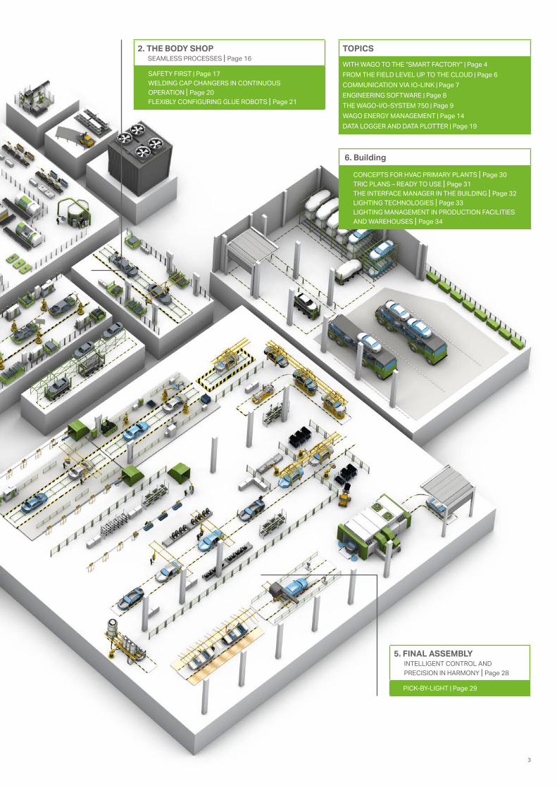
TOPICS
WITH WAGO TO THE “SMART FACTORY” ׀ Page 4FROM THE FIELD LEVEL UP TO THE CLOUD ׀ Page 6COMMUNICATION VIA IO-LINK ׀ Page 7ENGINEERING SOFTWARE ׀ Page 8THE WAGO-I/O-SYSTEM 750 ׀ Page 9WAGO ENERGY MANAGEMENT ׀ Page 14DATA LOGGER AND DATA PLOTTER ׀ Page 19
5. FINAL ASSEMBLY INTELLIGENT CONTROL AND PRECISION IN HARMONY ׀ Page 28
PICK-BY-LIGHT ׀ Page 29
2. THE BODY SHOP SEAMLESS PROCESSES ׀ Page 16
SAFETY FIRST ׀ Page 17WELDING CAP CHANGERS IN CONTINUOUS OPERATION ׀ Page 20 FLEXIBLY CONFIGURING GLUE ROBOTS ׀ Page 21
6. Building
CONCEPTS FOR HVAC PRIMARY PLANTS ׀ Page 30TRIC PLANS – READY TO USE ׀ Page 31THE INTERFACE MANAGER IN THE BUILDING ׀ Page 32LIGHTING TECHNOLOGIES ׀ Page 33LIGHTING MANAGEMENT IN PRODUCTION FACILITIES AND WAREHOUSES ׀ Page 34
3

0%
50%
100%
0102
0304
0506
The production line of the future will not only be networked and intelligent, it will possess some self-control and self-optimization capabilities, making it resource-efficient. Using machine learn-ing, it will be possible, for example, to use process and machine data for predictive maintenance.
Technology and pragmatism have equally shaped the development of Industry 4.0 topics: invest-ments in network infrastructure, data security and data transparency – and ultimately investments in horizontal and vertical integration – all make production more cost-effective.
WITH WAGO TO THE “SMART FACTORY”Industry 4.0 is Evolution
WAGO AUTOMATION
Against the background of global competition and the demand for a higher degree of product customization, this objective is crucial.
I/O-SystemsAt WAGO, you will find the exact I/O components you need: whether industrial, process or building automation, sensitive safety applications, telecon-trol or in hazardous areas. WAGO’s 750 Series and 750 XTR I/O-Systems reliably collect and transfer all signals in your installation.
Intelligent and Networked: Production of the Future
With its I/O systems and PFC line of controllers, WAGO always offers you exactly the components you need.
4

WAGO AUTOMATION
More than 500 modules and the powerful PFC line of controllers offer an appropriate solution for nearly any application. And these advantages also apply to integration into existing systems. Interna-tional certifications mean that these systems can be used worldwide in virtually any industry.
To maximize resource efficiency during produc-tion, you need transparent information on produc-tion procedures, performance and quality. And the way to achieve this is by ensuring all components are networked and “speaking” to each other (as well as us) during the value creation process.
As the leader in screwless interconnect and electron-ic interface technologies, WAGO developed the first finely modular, fieldbus-independent I/O system in 1995. To this day, our steadfast commitment to inno-vation and versatility has enabled us to continue set-ting new standards in usability, performance and reli-ability. A compact design combined with the highest quality standards has made the WAGO-I/O-SYSTEM one of the world’s most decentralized I/O systems.
5

FROM THE FIELD LEVEL UP TO THE CLOUD – THE NEW WAGO CLOUD DATA CONTROL
Everything from a single source: in addition to the PFC100 and PFC200 IoT Controllers, WAGO is expanding its digital performance portfolio with new WAGO Cloud Data Control capability. This ex-pansion allows WAGO to offer a solution that links elements from the real and digital worlds.
A Holistic Approach: from the Field Level up to the Cloud
WAGO Cloud Data Control manages and monitors all WAGO PFC Controllers, as well as their appli-cations and data. A Web portal serves as a user interface for the cloud service hosted at Microsoft Azure. Customers have access to functions – like project, controller, and user management, control-ler status monitoring, alarm functions, and email messaging – through this gateway. A dashboard displays text, tables, diagrams, display elements and command buttons for seamless and intuitive operation. For customized solutions, the REST or OPC UA interface is used for example, in energy monitoring and predictive maintenance applica-tions.
Impressive Hardware
The WAGO-I/O-SYSTEM 750 and the 750 XTR both connect to the field level, and a PFC Controller sends data to the Cloud Data Control. Communi-cation between PFCs and Cloud Data Control is performed and encrypted via MQTT protocol. The cloud connection data is configured via Web-Based Management (WBM). With the appropriate library, the variables that will be transferred to the cloud can be defined using the IEC program. This means that sensitive data does not leave the company. Thus, both WAGO PFC100 and PFC200 Controllers form the platform that links elements from the real and digital worlds. They also offer a variety of in-terfaces, forming the perfect foundation for an IoT gateway. These modular and scalable controllers collect every field signal, communicate in all indus-trial protocols, and even enable cloud connection to sensors and actuators that themselves have no Web interface. Thanks to the standard MQTT proto-col, it is also possible to connect to cloud services such as Microsoft Azure, Amazon Web Services or IBM Bluemix.
The WAGO Cloud Data Control is available for free as a beta version until the end of June 2018.
6
Connecting PFC Controllers directly to a cloud
PFC
ETHERNETMQTT
PFC

IO-DD
W
1 92 103 114 125 13 6 14 7 15 8 16
750-657
13 14
PROFINET PROFINET
IO-Link
Tool 3
Tool 4
Tool 2
W
Tool 1
COMMUNICATION VIA IO-LINKThe Foundation for the “Networked Smart Factory”
Intelligent and networked production is an essential part of any “smart factory” and thus of central importance during the development of Industry 4.0. The conversion of machines and plants in the course of a model change is an elaborate, time-critical and costly process. Here, as an automobile manufacturer, you are forced to constantly optimize changeover, commissioning and assembly times.
With IO-Link, the communication system for connecting intelligent sensors and actuators to an automation system, significant savings can be made. Sensors and actuators do not have to be replaced during production changeover, but only parameterized, if they are “intelligent.” The sen-sors and actuators manufacturers already offer a comprehensive range of products.
IO-Link communication also offers decisive advantages when making necessary adjustments during operation. If, for example, a defective sen-sor or actuator has to be replaced, the parameters stored in the IO-Link master can be transferred to the new device. Several process values can be read out simultaneously from sensors. This can save you additional costs.
The WAGO IO-Link Master can be easily integrat-ed into the WAGO-I/O-SYSTEM 750 as a module. Four different IO-Link devices or standard digital sensors/actuators can simultaneously connect to a module. Process data and acyclic data for identification, configuration and parameterization can be communicated to the respective device via 3-wire connection.
Line Control Central Configuration WAGO-I/O-CHECK
Decentralized Configuration
Line Control
7

COCKPIT
COCKPIT
Ready for Virtually Any Automation Requirement
ENGINEERING SOFTWARE
• Integrated engineering: one software for every task
• A smart design that invites you to discover • State-of-the-art software: comprehensive data
retention and automatic online upgrades • Based on CODESYS 3 technology • Graphical network configuration
Based on CODESYS 3
• Efficiently translate between programming languages
• Automatic variable declaration • Library management• Online status display using
the program code • Offline simulation and integrated
process visualization• Record and graphically display
project variables
Based on CODESYS 2.3
Software Factors into Success
Today’s mechanical engineering and related industries are characterized by ever-shortening development times, exponentially more complex projects and the increasing role of software as part of the overall solution. In fact, software is becoming an essential factor that influences the success of your project.
Linux® and WAGO – Automation for the Future
WAGO’s Microsoft Windows-based engineering software perfectly dovetails with our controller portfolio that features the Linux® operating system. In addition to their scalability through the open-source community, the Linux®-based controllers boast a code base that can rise up to any future challenges. WAGO’s controllers offer programming in either IEC 61131 with CODESYS or directly in Linux® to create complex tasks.
CODESYS – as an Integrated Environment
All WAGO controllers are equipped with the high-performing CODESYS industry standard. This enables software development in the IEC 61131-3 PLC programming languages (ST, FBD, LD, IL, SFC and CFC). As a trusted programming environment, CODESYS guides developers, enabling them to reuse and further develop existing programs with-out relearning software. This means that modern paradigms, such as Object-Oriented Programming (OOP), or modern visualization technologies are available.
WAGO-I/O-PRO
8

The Right Fieldbus Coupler and Controller for Every Application
FIELDBUS-INDEPENDENT AND MODULAR
Fieldbus Couplers
• Fieldbus couplers connect the WAGO‐I/O-SYSTEM 750 to a higher-level control system
• Fieldbus-independent – support all standard fieldbus protocols and ETHERNET standards
• For eXTReme environments
750 Series Controllers
• Controllers for all prominent fieldbus systems and ETHERNET standards
• Quick commissioning • Programmable via CODESYS
per IEC 61131-3• Directly connect to a wide range
of I/O modules within the WAGO-I/O-SYSTEM 750
• Flexible platform adapts to diverse applications and environments
• Tough enough for eXTReme envi-ronments
PFC Controllers
• High processing speed and a wide variety of interfaces
• Cost-effective configuration via e!COCKPIT (CODESYS 3) Engineering Software
• Superior investment protection due to scalable control technology
• Linux® real-time operating system• High level security with TLS, SSH,
OpenVPN/IPsec and a firewall• Send and receive data to the cloud
via MQTT• Tough enough for eXTReme
environments
9

GROUNDING EQUIP 64KA
I/O-SYSTEMS FROM WAGO: UNIVERSAL, COMPACT, ECONOMICALAlways Included: The I/O Components You Need
Maximum Fieldbus IndependenceThe system’s modularity is also reflected in its sup-port for numerous fieldbus systems and ETHER-NET standards. Depending on the application, it is possible to choose between fieldbus couplers and communication modules for different protocols.
Worldwide ApprovalsInternational approvals for building and industrial automation, as well as the process and marine industries, guarantee worldwide use – even under harsh operating conditions. These recognitions include: ATEX, BR-Ex, IECEx, UL, UL ANSI/ISA and numerous marine certifications.
Clear IdentificationModule functionality is identified via integrated or pluggable marker carriers. Terminal assignment and technical data are printed onto the side of the I/O module. The WAGO WSB marker system also allows for module- and channel-related identification.
Extremely Compact WAGO’s patented mechanical design leads to extremely compact I/O nodes. In fact, it can accom-modate up to 16 channels in a module width of 12 mm (1/2″).The finely granular and space-saving I/O modules provide both node customization and high I/O integration density.
10

Pluggable ConnectionsFor the ultimate convenience, 753 Series I/O Modules are compatible with the 750 Series and feature pluggable connectors. A detachable wiring interface allows an operator to easily replace a module without removing and then rewiring all pre-existing wiring. This convenience virtually eliminates installation errors and saves time, providing flexible and time-saving final assembly via pre-wired connectors.
Maximum Reliability and RuggednessThe WAGO-I/O-SYSTEM is engineered and tested for use in the most demanding environments in accordance with the highest standards, e.g., those required in marine applications. The system is distinguished from other products that are solely intended for industrial use because of:• Greatly increased vibration rating• Significantly greater immunity to interference
(ESD)• Low EMC emission of interference• Larger voltage fluctuation range• Greater durability for continuous operation in
upper temperature ranges
In addition, CAGE CLAMP® spring pressure con-nections ensure superior reliability. Integrated QA measures in the production process and 100% function testing ensure consistent quality.
Maximum FlexibilityEach node in the WAGO-I/O-SYSTEM can be configured to meet every channel’s requirements; various potentials and signal types are available (granularity of 1–16 channels). Digital and analog I/O modules, as well as specialty modules, can be freely mixed in the same node. Supply modules permit different voltages within the same node.
Easy to UseA modular, DIN-rail-mount design permits easy installation, expansion and modification of the I/O node without tools. The straightforward design prevents installation errors. In addition, proven CAGE CLAMP® technology offers fast, vibra-tion-proof and maintenance-free connections that are independent of operator skill. Depending on the I/O module’s granularity, field peripherals can be directly wired using 1-, 2-, 3- or 4-wire technology.
11

WAGO’s high-current, rail-mount terminal blocks offer
perfect clamping force, inde-pendent of operator skill.
High-Current, Rail-Mount Terminal Blocks with POWER CAGE CLAMP
The key to WAGO’s success: springs, not screws. This design gives POWER CAGE CLAMP the appropriate clamping force for 35, 50, 95 and 185 mm2 (2, 2/0, 4/0 AWG and 350 kcmil) conductors.
WAGO’s high-current, rail-mount terminal blocks meet the most stringent requirements. They resist hot and cold – even under the heaviest of loads. The terminal blocks can be quickly wired – no time-consuming preparation with ring terminals or ferrules required. WAGO’s blocks offer perfect clamping force, independent of operator skill.
In short, they are: vibration-proof – fast – maintenance-free!
By using power taps, even smaller conductors can be effortlessly connected. Convenient accesso-ries, such as jumpers, warning cover, test adapter, continuous marking strip and WMB markers, are also available.
OPTIMUM CLAMPING FORCE UP TO 185 MM² (350 KCMIL)
THE PRESS SHOPStable Processes Through High-Performance Components from WAGO
Finished body parts are constructed in a variety of steps in a press shop. Metal plates, smaller rectangle-shaped plates, trapezes or special geometric shapes are then punched from these flat metal strips.
1. The plates are then added to individual flows via springs or robots and transferred to next step. Mechanical or hydraulic presses bring the plates into a three-dimensional shape at high pressure.
12
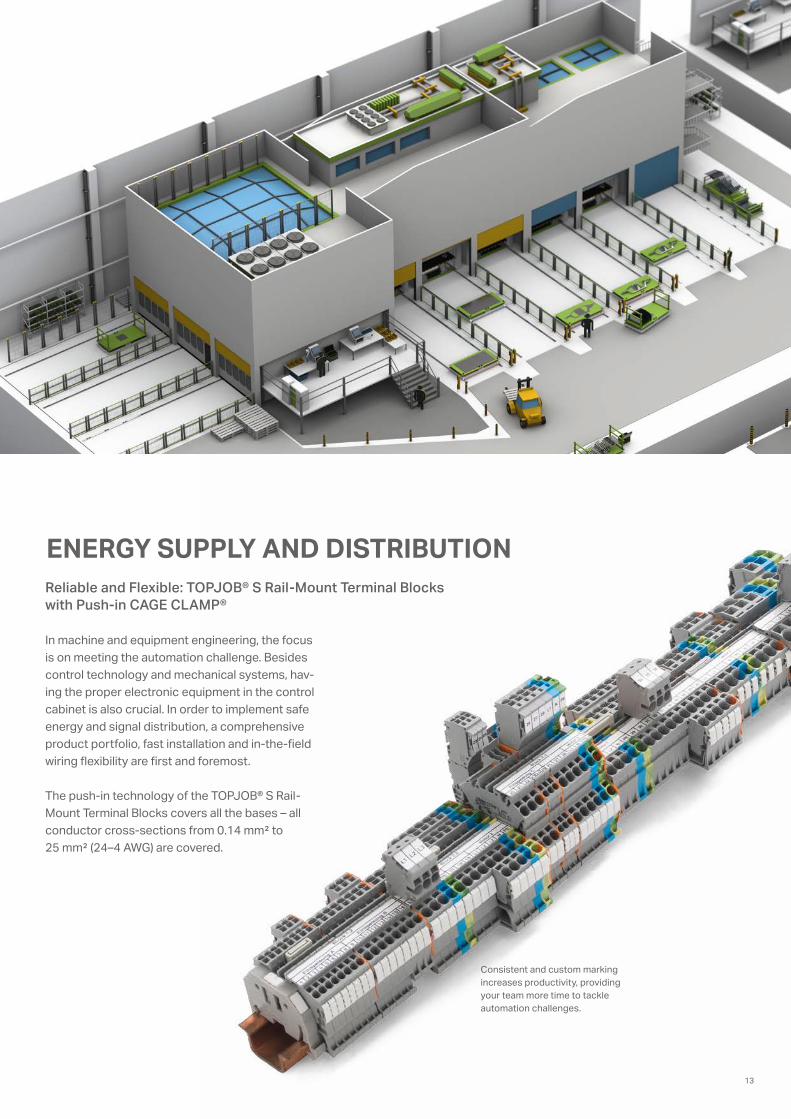
Consistent and custom marking increases productivity, providing your team more time to tackle automation challenges.
ENERGY SUPPLY AND DISTRIBUTIONReliable and Flexible: TOPJOB® S Rail-Mount Terminal Blocks with Push-in CAGE CLAMP®
In machine and equipment engineering, the focus is on meeting the automation challenge. Besides control technology and mechanical systems, hav-ing the proper electronic equipment in the control cabinet is also crucial. In order to implement safe energy and signal distribution, a comprehensive product portfolio, fast installation and in-the-field wiring flexibility are first and foremost.
The push-in technology of the TOPJOB® S Rail-Mount Terminal Blocks covers all the bases – all conductor cross-sections from 0.14 mm² to 25 mm² (24–4 AWG) are covered.
13

Transparency Pays Back
Complementary electricity and energy measure-ment solutions enable comprehensive consumption recording to create a base for determining relevant efficiency ratios. It is only through this transparency that potential savings can be discovered and, through appropriate measures, considerable cost savings can be realized. This also particularly ap-plies to large-scale consumers, such as the press or body shop in an auto plant.
WAGO ENERGY MANAGEMENT – EFFICIENCY IS THAT EASYModular Energy Data Collection
Measuring – Systematically Record Energy Consumption
Anywhere high currents must be measured and pro-cessed, plug-in current transformers are always the first choice. If existing systems will be retrofitted, save time by using Rogowski coils to avoid disas-sembling cables or interrupting processes.
PARAMETERIZING VISUALIZING
CONVERTING
14

Evaluating – Identifying and Planning Energy Use
Three 3-phase power measurement modules within the WAGO-I/O-SYSTEM 750 are available in the standard version for recording and evaluating all relevant metrics from a three-phase supply network. An XTR variant is also available for applications in extreme environments. This allows comprehensive network analysis to be performed and the power supply for machine drives to be optimally controlled, helping prevent damage, machine failures and downtime.
Parameterization and Visualization
Software solutions for the WAGO-I/O-SYSTEM and WAGO’s signal conditioners make parame-terization and visualization as simple as child’s play via the new WAGO Energy Data Management Application.
Cloud Connectivity
The MQTT software extension for the PFC100 and PFC200 Controllers allows data to be easily transmitted from the field level to the cloud. You can decide whether the controller sends the data to Microsoft Azure, Amazon Web Services, or IBM Bluemix.
CLOUD CONNECTIVITY(via MQTT)
EVALUATING
MEASURING
15

High-Performance Automation for High System Uptime
THE BODY SHOP
The molded sheet metal parts are further pro-cessed in the body shop. The body shells are assembled by gluing, welding or press-fitting techniques that use highly automated equipment and stationary industrial robots. Producing a body in white places maximum demands on system availability, as well as precision and protection of man and machine.
One of the greatest challenges in car body fabrication is permitting production of the widest variety of car bodies while meeting the highest demands for product quality, making high-perfor-mance automation essential. The target: highest system uptime with the lowest product error rate. System parts from different manufacturers must therefore fit seamlessly into the automated production process to achieve automation targets that exceed 90%.
16
2.

iPar-Server
SAFETY FIRST
Employee safety is the top priority in automotive production. For this reason, all safety-relevant systems are equipped with tamper-proof protec-tive devices, such as safety light grids, surface de-tectors and emergency stop buttons. Due to the modularization of systems, the safety controllers (fail-safe PLCs) are often installed “away” from the protective devices in the control cabinet.
In these cases, the WAGO-I/O-SYSTEM offers an economical and effective solution. Thanks to the support of PROFIsafe, based on PROFINET and PROFIBUS, the WAGO safety modules can be simply and quickly connected to the higher-level, fail-safe PLC in conjunction with PROFINET or PROFIBUS couplers. The WAGO safety modules
are quickly put into operation with the help of iPar server technology, in combination with simple parameterization via Tool Calling Interface (TCI).
WAGO offers module- and channel-related diag-nostics, which are supplemented by optional help documentation from the GSD/GSDML file, in order to quickly diagnose the modules in the event of a fault. This is an important aid for fast error detec-tion and helps you quickly resume production.
Easy Connection to the Fail-Safe PLC
The integration of different field devices suc-ceeds with the Tool Call by Interface (TCI) and the iPar Server.
17

The need to integrate a wide variety of field devices from different man-ufacturers is the result of complex production processes. With the definition of the TCI and iPar Server system services, the PROFIBUS User Organization e. V. (PNO) has created the basis for the integration of different field devices. Our graphs show the integration of the WAGO-I/O-SYSTEM in terms of functional safety using the WAGO-I/O-PROFIsafe-V2-iPar modules.
SEAMLESSLY INTEGRATING FIELD DEVICESTool Calling Interface (TCI) and iPar Server
iPar Server
Key Benefits of the Tool Calling Interface (TCI):
• Standardized interface for calling up manufacturing tools
• Communication via the fieldbus to the device with an interface
• Transfer of device and topology information
• Data backup in the project directory
Key Benefits of the iPar-Server:
• Safe recovery of module parameterization
• Module exchange without tooling• Exchange without special qualifi-
cations• Optimized WAGO solution available
➀ Instantiation of the iPar Server function
➁ CDP tool start and parameter transfer (e.g., node address)
➂ Module parameterization and commissioning; test and release
➃ Transfer of iPar CRC (signature) to the host
➄ Transfer of signature to F-slave during start-up (Prm_Telegram)
➅ Diagnostics message to iPar server (alarm/status)
➆ iPar server polls Diag-FB and starts “Save” if required
➇ iPar server polls Diag-FB and starts “Restore” if required
18
Engineering System (ES); e.g., Step 7
Proprietary Device Tools; e.g., WAGO-I/O-CHECK
Open Device Tools (FDT/EDDL); e.g., WAGOframe
TCI
F-SPSTCI Conformance Class 3
PROFIBUSPROFINET or
FDT-compliant Communication Tunnel to Fieldbus
F-Host/PLC IEC 61131-3F-IO Parameters (Instance Data)
iPar Server
RD/WRComm-FB
Query Diag-FB
DP Master
Ex.: TCI
“iPar_CRC” CPD Tool
F-Slave/F-Device
“Restore”
“Save”
“Message”
Prm_Telegram (F_iPar_CRC)
R
➀
➃
➁
➂
➄
➅
➆
➇
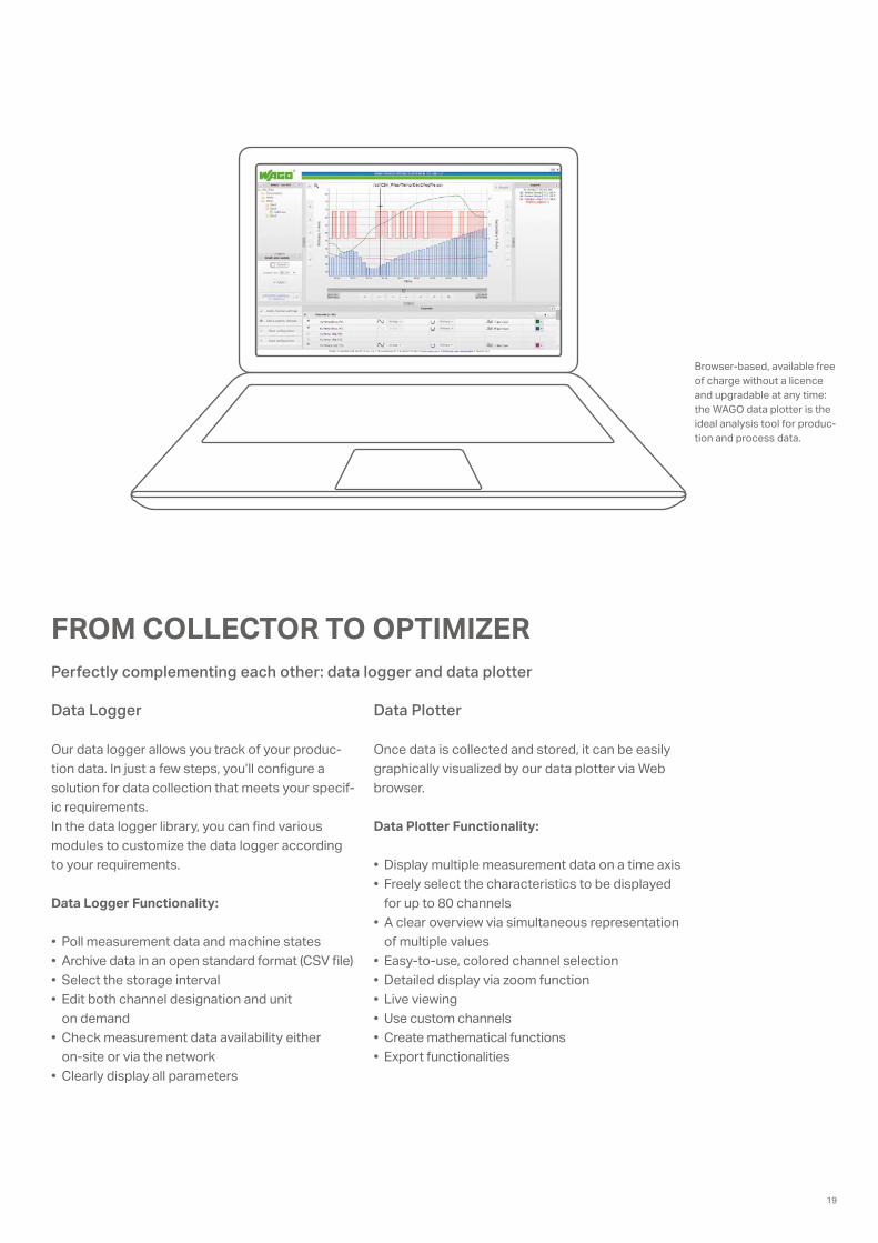
FROM COLLECTOR TO OPTIMIZERPerfectly complementing each other: data logger and data plotter
Data Plotter Data Logger
Our data logger allows you track of your produc-tion data. In just a few steps, you’ll configure a solution for data collection that meets your specif-ic requirements. In the data logger library, you can find various modules to customize the data logger according to your requirements.
Data Logger Functionality:
• Poll measurement data and machine states• Archive data in an open standard format (CSV file)• Select the storage interval• Edit both channel designation and unit
on demand• Check measurement data availability either
on-site or via the network• Clearly display all parameters
Once data is collected and stored, it can be easily graphically visualized by our data plotter via Web browser.
Data Plotter Functionality:
• Display multiple measurement data on a time axis• Freely select the characteristics to be displayed
for up to 80 channels• A clear overview via simultaneous representation
of multiple values• Easy-to-use, colored channel selection• Detailed display via zoom function• Live viewing• Use custom channels• Create mathematical functions• Export functionalities
Browser-based, available free of charge without a licence and upgradable at any time: the WAGO data plotter is the ideal analysis tool for produc-tion and process data.
19

WELDING CAP CHANGERS IN CONTINUOUS OPERATIONFast and Reliable Cap Replacement
Sheet metal parts are joined together using a welding gun via spot welding. The electric welding caps used for this are “wear parts” and must be replaced several times each day. Automatic cap changers allow safe and fast exchange.
The following requirements are placed on the machine’s control for fast and reliable cap replacement:• Fieldbus-independent• Compact design• Modular design• Secure contact of the connected conductors
The fieldbus-independent WAGO-I/O-SYSTEM 750 offers space-saving 12–24 mm wide modules including more than 500 different variants with nearly unlimited configuration and flexible applica-tion possibilities. WAGO’s proven CAGE CLAMP® spring pressure termination technology provides vibration-proof, fast and maintenance-free conductor connections. An extensive range of accessories for marking systems and connection technologies, as well as worldwide approvals are also available. The WAGO-I/O-SYSTEM 750 fulfills all requirements for perfectly controlling a welding cap changer!
20

iSto
ck.c
om/z
oraz
huan
g
FLEXIBLY CONFIGURING GLUE ROBOTSThe WAGO-I/O-SYSTEM 750 Keeps Setpoints Constant.
Adhesive joints are increasingly replacing spot or path welding. PLC controllers take over the pro-cess control of glue robots for this purpose. For example, this includes the monitoring and, where appropriate, adjusting temperature, filling level or dosing quantity based on measured values.
The modular WAGO-I/O-SYSTEM 750 solves these tasks simply and cost-effectively!
WAGO’s fieldbus couplers and controllers allow almost every system to be integrated using all standard fieldbus protocols and Industrial Ether-net standards.
The high flexibility and various configuration possibilities of digital or analog inputs or outputs, as well as both specialty and communication modules, make it possible to integrate all required signals into an executable program. This versatility allows the WAGO-I/O-SYSTEM 750 to take over the entire control, regulation and visualization of the gluing process.
ASM
DIM
ATEC
Gm
bH
21

© Eisenmann
THE PAINT SHOP
The paint shop in an automotive plant consists of several different steps.
For a trouble-free process and perfect paint finish, the continuous supply of required lacquers and foaming materials must be ensured.
In some paint shops, there are typically areas where there is a danger of explosion, and these must be protected by appropriate measures. The WAGO-I/O-SYSTEM 750 is ideal for exchanging signals between the PLC and the field level. The blue, intrinsically safe Ex i modules can easily be integrated into a standard I/O node. This enables the direct connection of sensors and actuators from Zones 0/20 and 1/21. Even the otherwise difficult safety connections are possible directly in and out of the Ex-i area.
Perfect Surfaces Through Seamless Processes
Blue, intrinsically safe Ex i mod-ules can easily be integrated into
a standard I/O node.
22
3.

EXPLOSION PROTECTION – BY WAGOWAGO Components Ensure Maximum Flexibility and Safety.
WAGO-I/O-SYSTEM 750
WAGO offers a universal system for reliable explo-sion protection in all sectors, including the special requirements of the automotive industry.
Benefits in Overview:
• Approved for Zone 2/22• Maintenance-free conductor connection via
CAGE CLAMP® termination technology• Comprehensive certification including ATEX
ensures use worldwide• IECEx, easy integration of intrinsically safe sig-
nals from the field up to Zone 0 (Ex ia) • Use intrinsically safe inputs with functional safe-
ty up to SIL 3, Cat. 4/ PL e, PROFIsafe
TOPJOB® S and POWER CAGE CLAMP
Rely on WAGO’s vibration-proof and mainte-nance-free, rail-mount terminal blocks to tackle real system challenges!
Benefits in Overview:
• Reliable connections from 0.14 to 185 mm² (24 AWG–350 kcmil)
• No need to retighten screws thanks to our spring pressure connection technology
• Ex e I/II approval
X-COM®S-SYSTEM
Modularize systems and improve system uptime via fast and flexible maintenance solutions. This is made possible using the world’s first pluggable, rail-mount terminal block system with Ex area approval.
23

THE POWERTRAIN
The term “powertrain” describes all the areas where components for the powertrain are produced, including, the production of engines, gearboxes, clutches and axles. When all these elements are unified, the entire powertrain of a vehicle is formed.
Finally, the assembled components must be avail-able at the right time at the correct location of the engine or gearbox assembly. This requires a high reliability of the automation solution.
In the case of assembly lines or processing cen-ters, as used in powertrain areas, a safe start-up of the systems and, in the event of a fault, the safe shutdown and restart of a defined condition must always be ensured.
The aim of this requirement is the prevention of avoidable errors in the power supply and associat-ed downtime. Here, too, the production costs must be kept in mind and efficiency has to be increased.
The EPSITRON® family of power supplies and circuit breakers was engineered to readily meet these requirements.
WAGO’s 787 Series electronic fuses help prevent accidental tripping that results from high switch-on currents or the unintended startup of equip-ment that’s triggered by a fault. Function blocks for ECB monitoring that use the WAGO-I/O-SYS-TEM, or other control systems, are available for free. Electronic circuit breakers (ECBs) have digital inputs and outputs that provide communication via Manchester protocol. All channels can be diag-nosed and switched remotely and independently of each other. These options allow plant operators to implement preventive maintenance and reduce costly production downtime.
Complex Value Creation Needs High Reliability
24
4.

® 1
ADVANCED POWER SUPPLY SYSTEMEPSITRON® PRO Power – Professional and Efficient Power Supplies with Extra Power
Applications with high output requirements call for professional power supplies capable of reliably handling power peaks. These applications call for PRO Power Supplies, which provide 24 VDC with nominal output currents of 5 A to 40 A in a slim vertical- or horizontal-mount housing. An integrated PowerBoost function provides 200% of the rated current for up to four seconds, enabling start-up or switching of capacitive loads, valve clusters or motors. The TopBoost function pro-vides sufficient power with a multiple of the rated current for up to 50ms, permitting use of standard circuit breakers for output protection. An optional LineMonitor provides easy parameter setting and monitoring of input and output. This eliminates redundant devices, such as phase and frequency monitoring units, as well as operational hour me-
ters in control cabinets. EPSITRON® PRO Power Supplies set a new standard in energy-efficiency with up to 93% efficiency and a stand-by mode.
WAGO’s CAGE CLAMP® Spring Pressure Con-nection Technology provides fast, vibration-proof and maintenance-free connection of solid, fine-stranded or ferruled conductors. Clearly la-beled, pluggable female connectors allow for easy cable pre-assembly.
NEC Class 2(1)
(1) Observe note on data sheet
WAGO’s efficient power supplies always deliver a constant supply voltage – whether for simple applications or for
automation with greater power requirements. Our uninter-ruptible power supplies (UPS), buffer modules, redundancy modules and a wide range of electronic circuit breakers are
ideal additions to your system.
25

Adjust
DC OK
Overload
EPSITRON® ECO Power, 787-732
ECB, 787-1664
In the event of an accidental ground fault, the electronic circuit breaker reliably trips within five seconds based on EN 60204-1, preventing dan-gerous conditions.
Motor
EPSITRON® – ELECTRONIC CIRCUIT BREAKERS (ECBs)Compact and Precise ECBs for DC Circuits
© Nataliya Hora/Fotolia.com
ECB Advantages:
• Switch off secondary-side overcurrents and short circuits – even with long cable runs and small conductor cross-sections – precisely, fast and repeatedly
• Selectivity, especially with ECBs having active current limitation
• Remote operation via digital input and output• Readout functions (communication) through
serial data transfer via digital input and output
• Beneficial installation size and width, for example, 8 output channels in just 42 mm (save more than 70% of installation space compared to miniature circuit breakers)
• Nominal current assignable for each channel• Satisfy EN 60204-1 requirements for dependably
switching off ground faults after five seconds (see graphic)
26
Motor, Last 3 A
EPSITRON® – ELECTRONIC CIRCUIT BREAKERS (ECBs)
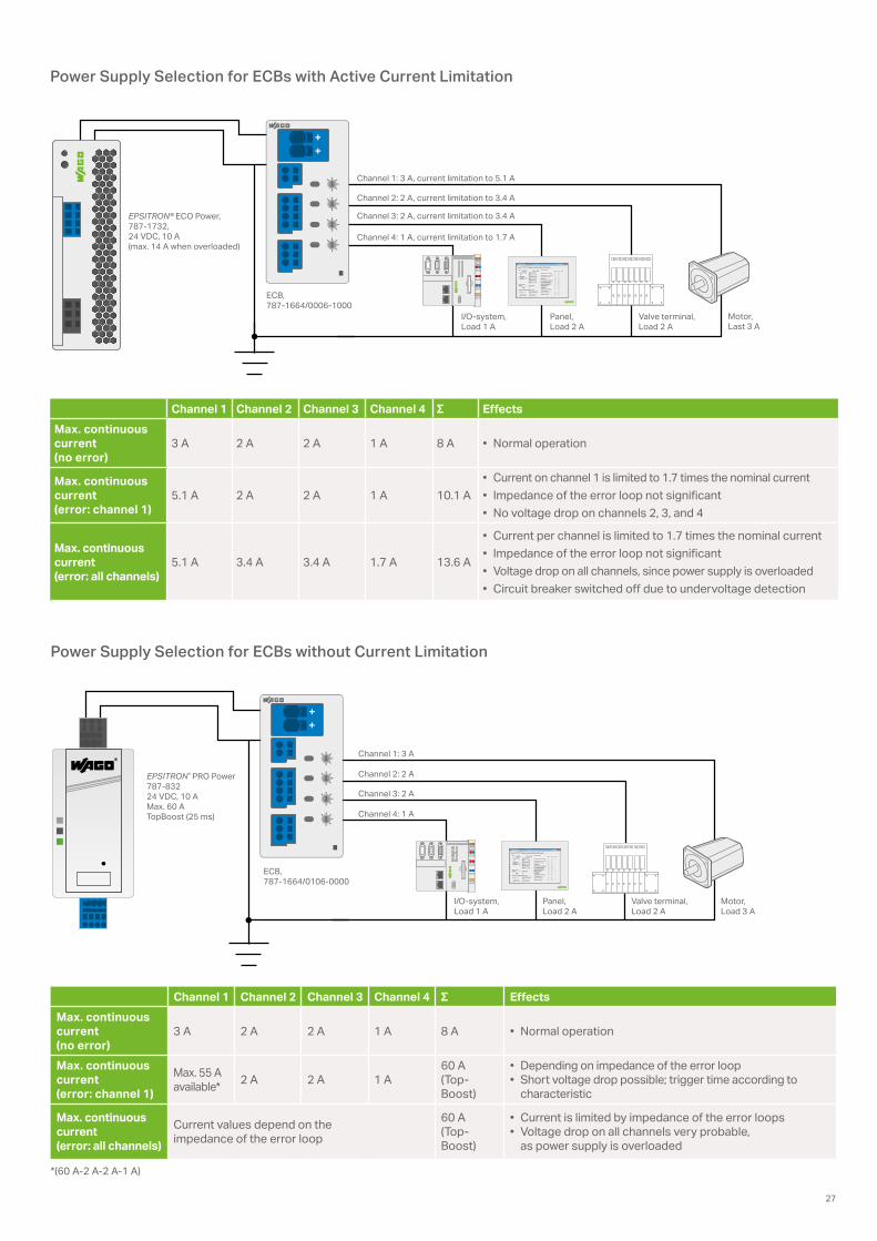
Power Supply Selection for ECBs with Active Current Limitation
Power Supply Selection for ECBs without Current Limitation
EPSITRON® ECO Power, 787-1732, 24 VDC, 10 A (max. 14 A when overloaded)
ECB, 787-1664/0006-1000
Channel 1: 3 A, current limitation to 5.1 A
Channel 2: 2 A, current limitation to 3.4 A
Channel 3: 2 A, current limitation to 3.4 A
Channel 4: 1 A, current limitation to 1.7 A
I/O-system, Load 1 A
Panel, Load 2 A
Valve terminal, Load 2 A
EPSITRON® PRO Power 787-832 24 VDC, 10 A Max. 60 A TopBoost (25 ms)
ECB, 787-1664/0106-0000
Channel 1: 3 A
Channel 2: 2 A
Channel 3: 2 A
I/O-system, Load 1 A
Panel, Load 2 A
Valve terminal, Load 2 A
Motor, Load 3 A
Channel 4: 1 A
Channel 1 Channel 2 Channel 3 Channel 4 Σ EffectsMax. continuous current (no error)
3 A 2 A 2 A 1 A 8 A • Normal operation
Max. continuous current (error: channel 1)
5.1 A 2 A 2 A 1 A 10.1 A• Current on channel 1 is limited to 1.7 times the nominal current• Impedance of the error loop not significant• No voltage drop on channels 2, 3, and 4
Max. continuous current (error: all channels)
5.1 A 3.4 A 3.4 A 1.7 A 13.6 A
• Current per channel is limited to 1.7 times the nominal current• Impedance of the error loop not significant• Voltage drop on all channels, since power supply is overloaded• Circuit breaker switched off due to undervoltage detection
Channel 1 Channel 2 Channel 3 Channel 4 Σ EffectsMax. continuous current (no error)
3 A 2 A 2 A 1 A 8 A • Normal operation
Max. continuous current (error: channel 1)
Max. 55 A available* 2 A 2 A 1 A
60 A (Top-Boost)
• Depending on impedance of the error loop• Short voltage drop possible; trigger time according to
characteristic
Max. continuous current (error: all channels)
Current values depend on the impedance of the error loop
60 A (Top-Boost)
• Current is limited by impedance of the error loops• Voltage drop on all channels very probable,
as power supply is overloaded
*(60 A-2 A-2 A-1 A)
27

FINAL ASSEMBLY
Within automobile production, final assembly completes the process. Here all necessary com-ponents are mounted in the interior and to the exterior of a vehicle. The most important step in final assembly is the “marriage,” i.e., the moment the drivetrain and engine are bolted to the body. Before that, and in the subsequent steps, steps are taken to meet customized orders.
A high degree of precision and intelligent control ensures that custom parts are mounted in the correct order at the defined location. In addition, various safety fittings must be checked and stored automatically. Therefore, particularly high requirements are placed on the control system used. A production stop is not acceptable in final assembly.
Intelligent Control and Precision in Harmony
Functional safety: the WAGO-I/O-SYSTEM 750/753 with PROFIsafe
functions can be used flexibly thanks to easy parameterization
and extensive diagnostics options.
28
5.

PICK-BY-LIGHTAlways the Right Grip: With and Thanks to the WAGO-I/O-SYSTEM
Pick-by-Light is a “paperless picking procedure.” In automotive assembly, the operator is guided by means of a light to the pickup box of the next component that will be mounted. In this process, the sequence and the number of the removed components are monitored. If the sequence is not adhered to, or the wrong number of components are removed, the conveyor belt is stopped and the vehicle does not move along. Such a pick-by-light system is used in almost every final assembly process within an automobile factory. With this “system-guided assembly,” a 100% safe assembly despite a high variety of variants is ensured. An important prerequisite for a system’s reliability is a reliable and flexible control solution.
The WAGO-I/O-SYSTEM with its extensive, distrib-uted periphery offers you the perfect synergy of flexibility and standardization. The large number of available fieldbus couplers and controllers en-ables connection of a pick-by-light system to a higher-level control system.
The I/O level remains unchanged. For example, this makes a change from PROFIBUS to PROFINET without rewiring possible. This flexibility saves time and money, e.g., during commissioning.
The WAGO controllers are an excellent choice for controlling a pick-by-light storage facility. Thanks to direct connection to higher-level control systems with MySQL or MSQL, for example, the WAGO con-troller can communicate directly with the database. WAGO’s PFC Controllers with the Linux® operating system offer you additional flexibility. WAGO’s con-trollers offer programming in either IEC 61131 with e!COCKPIT or directly in Linux® to create complex tasks.
29

HVAC PRIMARY SYSTEM SOLUTIONSAn Efficient Process: Step-by-Step
Energy efficiency hinges on sensibly planning a building’s technical systems. Modern automation systems conveniently combine all possible proto-cols and interfaces into one system – as opposed to the requirements of larger properties with mixed forms.
The WAGO-I/O-SYSTEM 750 is the hardware solu-tion to meet this challenge. The controller, which takes on control tasks for building automation, can be easily expanded using various I/O systems – virtually any device can be connected to the system.
Configuration, programming and visualization are easily performed using WAGO’s available software packages. In addition to building automation, WAGO has a well-established track record in building installations. This experience is reflected in WAGO’s integrated approach that cost-effec-tively combines these two worlds.
© s
ssss
1gm
el/p
anth
erm
edia
.net
30
6.

Hand
Auf
Hand
Ein0 %
StatusmeldungenSammelstörung:Vorspülen:Mischluftklappe:
OkVorspülen beendetEin
Fortluftklappe:Zuluftventilator:Abluftventilator:
geö�netOkOk
Sensorwerte übersteuern
Störung
Quit
Y = 30.8 %
Y = 17.6 %
18.0°C
12.0°C
31.0°C
18.0°C22.0°C
30 %
25 % 0 %
15.0°C10.0°C
200 Pa200 Pa
200 Pa200 Pa
TRIC PLANS – READY TO USEFrom System Diagram to the Finished Application
System Diagrams
Matching the applications, standardized system diagrams for CAD and TRIC are available for easy integration into current plans.
System Macros
WAGO provides comprehensive templates, which include ready-made system macros for many common applications. This time-saving conve-nience minimizes HVAC configuration for users.
After rapidly configuring the application – via simple data point and system parameter assign-ment – the ready-made application can be directly commissioned.
To simplify programming, there are a multitude of pre-configured function blocks and applications available free of charge in the download area. In addition, there are templates for creating programs. These comprehensive examples of complex tasks – including functional system macros with the appropriate documentation — are available in PDF format. The manual override function within the system macros allows the operator to override individual system parts using the visualization screens.
31
21,0 °C
▸ ▸ ▸
▸
StatusmeldungenSammelstörung:Vorspülen:Zuluftklappe:
OkVorspülen beendetgeö�net
Abluftklappe:Zuluftventilator:Abluftventilator:
geö�netOkOk
Level 2
Level 2
Sensorwerte übersteuern
Störung
Quit
12.0°C
31.0°C
15.0°C
100 % 0 %
18.0°C28.0°C
20.0°C22.0°C
Kon�gurationStartseite
I/O
NS
MS
LINKACTLINKACT
USR
X1
Termination+BIASON/OFF
Default IP
X2
750-
829
BACnet/IP
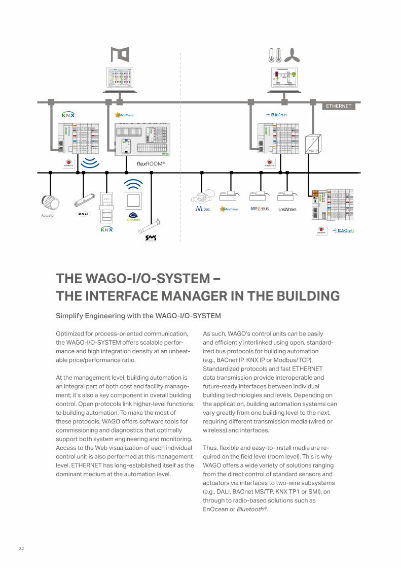
THE WAGO-I/O-SYSTEM – THE INTERFACE MANAGER IN THE BUILDINGSimplify Engineering with the WAGO-I/O-SYSTEM
Optimized for process-oriented communication, the WAGO-I/O-SYSTEM offers scalable perfor-mance and high integration density at an unbeat-able price/performance ratio.
At the management level, building automation is an integral part of both cost and facility manage-ment; it’s also a key component in overall building control. Open protocols link higher-level functions to building automation. To make the most of these protocols, WAGO offers software tools for commissioning and diagnostics that optimally support both system engineering and monitoring. Access to the Web visualization of each individual control unit is also performed at this management level. ETHERNET has long-established itself as the dominant medium at the automation level.
As such, WAGO’s control units can be easily and efficiently interlinked using open, standard-ized bus protocols for building automation (e.g., BACnet IP, KNX IP or Modbus/TCP). Standardized protocols and fast ETHERNET data transmission provide interoperable and future-ready interfaces between individual building technologies and levels. Depending on the application, building automation systems can vary greatly from one building level to the next, requiring different transmission media (wired or wireless) and interfaces.
Thus, flexible and easy-to-install media are re-quired on the field level (room level). This is why WAGO offers a wide variety of solutions ranging from the direct control of standard sensors and actuators via interfaces to two-wire subsystems (e.g., DALI, BACnet MS/TP, KNX TP1 or SMI), on through to radio-based solutions such as EnOcean or Bluetooth®.
MS/TP
IP
flexROOM®
ETHERNET
Actuator
32
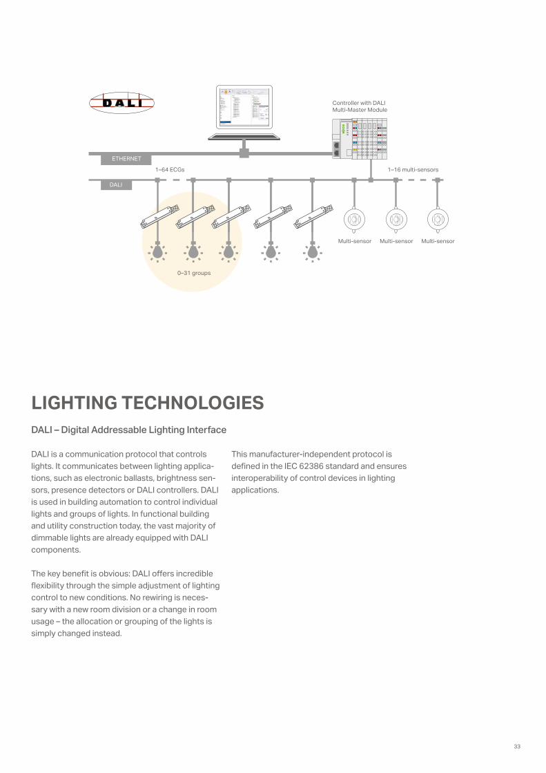
LIGHTING TECHNOLOGIESDALI – Digital Addressable Lighting Interface
DALI is a communication protocol that controls lights. It communicates between lighting applica-tions, such as electronic ballasts, brightness sen-sors, presence detectors or DALI controllers. DALI is used in building automation to control individual lights and groups of lights. In functional building and utility construction today, the vast majority of dimmable lights are already equipped with DALI components.
The key benefit is obvious: DALI offers incredible flexibility through the simple adjustment of lighting control to new conditions. No rewiring is neces-sary with a new room division or a change in room usage – the allocation or grouping of the lights is simply changed instead.
This manufacturer-independent protocol is defined in the IEC 62386 standard and ensures interoperability of control devices in lighting applications.
ETHERNET
1–16 multi-sensors
Multi-sensor Multi-sensor Multi-sensor
0–31 groups
DALI
1–64 ECGs
Controller with DALI Multi-Master Module
33

LIGHTING MANAGEMENTThe Solution for Efficient Lighting Management in Production Facilities and Warehouses
Modern lighting management offers more than merely reducing energy consumption and costs, it simplifies economizing and resource conservation while maintaining user comfort and flexibility.
Our ConceptWAGO Lighting Management is a proven concept based on predefined hardware and preconfig-ured software, which greatly simplifies planning, commissioning and operation. The basic idea: WAGO Lighting Management is based on different lighting requirements in warehouses and produc-tion facilities. For example, a production facility is divided into virtual rooms in which the light can be flexibly adapted. Each virtual room receives signals from sensors and actuators in order to automatically set the appropriate light intensity. By using the virtual rooms, conversions and room re-modeling can be implemented quickly and simply via Web configuration.
OperationWAGO Light Management features a Web in-terface that allows you to easily create and edit virtual rooms. Do you need to illuminate a produc-tion line, hallway or a storage area? No problem – simply create three different rooms with the required functions. Parameter values are stored on an SD card or a backup server via FTP. The values can be forwarded to a higher-level building control system or to a production control center via Modbus TCP/IP.
© iS
tock
.com
/jkita
n
34

The Solution for Efficient Lighting Management in Production Facilities and Warehouses
WAGO Lighting Management significantly reduces the overall costs of new installations and conver-sions. WAGO Lighting Management provides the perfect combination of high-quality hardware and
Advantages of WAGO Lighting Management: • Reduce lifecycle costs through efficient lighting
management• Scalable to any system requirement• Commissioning via easy, wizard-based configuration• Simple, programming-free conversion• Connect to higher-level management and control
systems within industrial or building technology environments
Works photo, WAGO
intuitive custom software! Reduce lifecycle costs with quick and simple commissioning, good diag-nostic and service capabilities and simple adapta-tion of lighting situation to varying requirements.
Example of typical production facility lighting
Do you need to illuminate a large area?
No problem! Our Lighting Management application allows you to illuminate nearly 3000 m² depending on the type of lamp. For larger areas, it is easy to link a number of controllers with one another.
35

0888
-012
4/01
00-6
901
– AU
TOM
OTI
VE B
ROC
HUR
E 1.
0 US
– 0
8/20
17 –
Prin
ted
in G
erm
any
– Su
bjec
t to
desi
gn c
hang
es
Headquarters +49 (0)571/ 887 - 0Sales +49 (0)571/ 887 - 222Orders +49 (0)571/ 887 - 44 333Fax +49 (0)571/ 887 - 844 169
WAGO Kontakttechnik GmbH & Co. KGPostfach 2880 · 32385 Minden, GermanyHansastraße 27 · 32423 [email protected]
WAGO is a registered trademark of WAGO Verwaltungsgesellschaft mbH. Cover image: Nataliya Hora/Fotolia.com“Copyright – WAGO Kontakttechnik GmbH & Co. KG – All rights reserved. The content and structure of the WAGO websites, catalogs, videos and other WAGO media are subject to copy-right. Distribution or modification to the contents of these pages and videos is prohibited. Furthermore, the content may neither be copied nor made available to third parties for commer-cial purposes. Also subject to copyright are the images and videos that were made available to WAGO Kontakttechnik GmbH & Co. KG by third parties.”