autonomous control of the cal poly motion flight simulator
TRANSCRIPT

Autonomous Control of the Cal Poly Motion Flight Simulator
A Senior Project
presented to
the Faculty of the Aerospace Engineering Department
California Polytechnic State University, San Luis Obispo
In Partial Fulfillment
of the Requirements for the Degree
Bachelor of Science
by
Andrew Anderson
June, 2010
© 2010 Andrew Anderson

1
An autonomous controller for the Cal Poly Motion Flight Simulator was developed such
that the simulated Van’s RV-7 flies a standard light aircraft traffic pattern without any
human pilot input. First, an autopilot was developed in Simulink to control the aircraft’s
altitude, airspeed, and heading independent of each other. The performance of the autopilot
has been tested to perform with a response sufficient for precise navigation. A C++ s-
function was written as a mission controller that followed a preprogrammed path around a
known airport. The aircraft performs a standard left 45 degree entry into the traffic pattern,
lands on the runway, and either choose to stop or perform a touch-and-go based on the
preprogrammed command.
Nomenclature
Acronyms
ACL = Autonomous control level
AGL = Above ground level
GA = General aviation
kias = knots indicated airspeed
MFS = Motion flight simulator
UAV = Unmanned aerial vehicle
Variables
R = Range to waypoint
δa = Aileron deflection
δe = Elevator deflection
δt = Throttle position
ψ = Heading with respect to true north

2
I. Introduction
HE Cal Poly Motion Flight Simulator (MFS) is a student built and student maintained aircraft simulator. It is
built around a six degree-of-freedom mathematical model in Simulink that was originally developed as an F-4
Phantom simulator. With the acquisition of a Van’s RV-7 fuselage and a motion platform from InMotion
Simulation, the flight simulator is modified with the stability derivatives of an RV-7. In addition, the apparent forces
felt by the pilot in the aircraft are output to the motion controller to move the cab appropriately. The graphical output
that the pilot sees is generated by commercial software called X-Plane, developed by Austin Meyers. This is
achieved by disabling the physics modeling of X-Plane and substituting in the position and orientation of the aircraft
into the software.
The MFS is a great development tool for students due to its modular design. Components of the simulator are
isolated into blocks that modify global variables with the use of tags. A new component can be quickly developed in
its own block and dropped into the simulation for testing. The aircraft being simulated is defined by a file containing
tables of aircraft stability derivatives. If another aircraft is desired, its stability derivates can be placed into this file,
and the new aircraft can be flown by the simulator. Airport information can be added to the simulator via its own
file. All these files allow for extensive modifications of the flight simulator for use by student research. The
Simulink diagram for the MFS is shown in Appendix A.
Current developments in the aerospace industry are trending towards removing pilots from the aircraft.
Unmanned aerial vehicles (UAVs) have the advantage of removing the pilot for dangerous missions, allowing the
aircraft to stay airborne longer than the stamina of the pilot and eliminating life support systems. These advantages
are not without their disadvantages. Air Force researchers have determined three primary challenges with creating
UAVs [1]. First, a high level of intelligence is required to remove the pilot from situations that require reasoning.
Second, the UAV must have a level of safety installed that prevents the aircraft from performing undesirable actions.
Humans need to be able to trust the autonomous control as much as they would a human pilot. Lastly, the aircraft
needs to be affordable. Simple UAV systems reduce cost over a piloted aircraft, but as the complexity of the mission
being performed increases, so do the costs. These costs will need to be kept to a minimum in order to take advantage
of UAVs.
While the MFS is pilot-centric, it can be used to develop autonomous components by substituting the “Motion
Cab Controls” block with “Autonomous Control” block. In fact, an auto-land function was created for the F-4
T

3
Phantom simulation in 2005 by Jason Tolvtvar [2]. The senior project successfully developed a glide slope and flare
controller that was able to guide the aircraft through an approach, landing, and rollout of the aircraft. Lessons
learned from this project will be applied where appropriate to achieve the goals of my senior project.
II. Project Description
The primary objective of my senior project is to achieve autonomous control of the MFS with an autonomous
control level (ACL) of 1, where the aircraft can complete a preprogrammed mission successfully [1]. The mission
for this project is defined as flying a left closed traffic pattern for general aviation aircraft. Initially the flight will be
simulated at San Luis Obispo County Regional Airport, but with a proper setup of the simulation, the aircraft will be
able to complete the mission at any airport with the runway’s location, direction, and elevation known. An
additional objective is for the aircraft to perform a standard left 45 degree entry into the traffic pattern from any
airborne position outside of the airport’s airspace. After being able to fulfill these objectives the aircraft will be
capable of flying any navigation mission from one airport to another based on a preprogrammed route.
III. Autonomous Controller Development
In order to achieve the autonomous control of the aircraft, an autopilot and an autonomous “mission controller” need
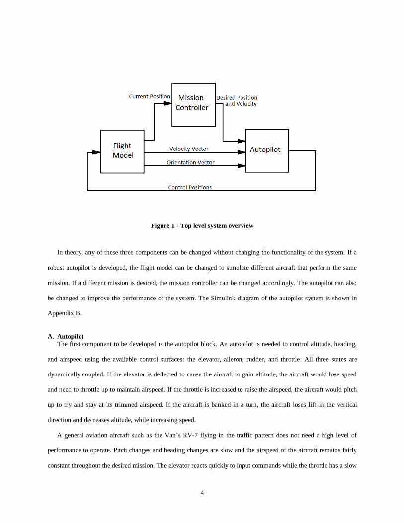
to be developed. As diagrammed in Fig. 1, the flight model outputs the aircrafts position, velocity and orientation. A
mission controller, whether a human operator or autonomous computer, decides where the airplane should go based
on its current location. This desired position is sent to the autopilot, which also gets velocity and orientation
information from the flight model. The autopilot then manipulates the control surfaces to move the aircraft to the
desired location.
4
.
Figure 1 - Top level system overview
In theory, any of these three components can be changed without changing the functionality of the system. If a
robust autopilot is developed, the flight model can be changed to simulate different aircraft that perform the same
mission. If a different mission is desired, the mission controller can be changed accordingly. The autopilot can also
be changed to improve the performance of the system. The Simulink diagram of the autopilot system is shown in
Appendix B.
A. Autopilot
The first component to be developed is the autopilot block. An autopilot is needed to control altitude, heading,
and airspeed using the available control surfaces: the elevator, aileron, rudder, and throttle. All three states are
dynamically coupled. If the elevator is deflected to cause the aircraft to gain altitude, the aircraft would lose speed
and need to throttle up to maintain airspeed. If the throttle is increased to raise the airspeed, the aircraft would pitch
up to try and stay at its trimmed airspeed. If the aircraft is banked in a turn, the aircraft loses lift in the vertical
direction and decreases altitude, while increasing speed.
A general aviation aircraft such as the Van’s RV-7 flying in the traffic pattern does not need a high level of
performance to operate. Pitch changes and heading changes are slow and the airspeed of the aircraft remains fairly
constant throughout the desired mission. The elevator reacts quickly to input commands while the throttle has a slow

5
response time allowing the elevator to minimize the coupled interaction between airspeed and altitude. This way the
autopilot system can be treated as a set of SISO systems as seen in Fig. 2.
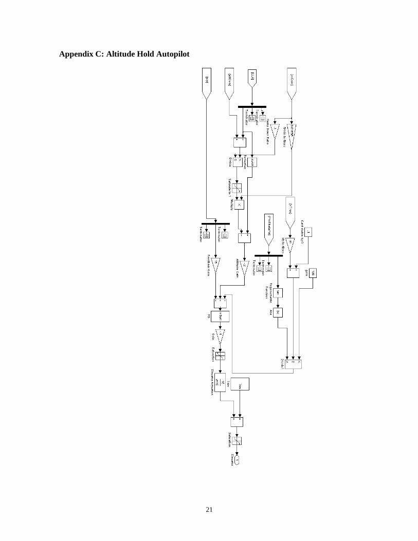
The altitude hold function was developed first by keeping the ailerons level and the throttle constant. As
recommended by Aircraft Control and Simulation [3], the altitude hold autopilot was designed around a pitch-
attitude hold, but instead of feeding back and commanding a specific pitch angle, the vertical velocity was used
instead. Pitch angle and vertical velocity are analogous to each other since at a constant airspeed and pitch angle, the
aircraft would have a constant vertical velocity. The outer loop of the controller feeds back the aircraft’s current
altitude. The error between the desired altitude and the actual altitude commands a vertical velocity to minimize the
error. The vertical velocity is limited to the maximum allowed vertical velocity set by the mission controller with a
ramp down at some ratio of vertical velocity from the target altitude. The middle feedback loop compared the
commanded vertical velocity with the actual vertical velocity and commands a pitch rate through a gain. The inner
loop compared the commanded pitch rate with the actual pitch rate to command an elevator deflection. The
commanded elevator deflection is run through an actuator to realistically model the elevator response. During testing
it was found that a steady state error was produced at off trim conditions. Thus elevator trim was added by putting
Figure 2 - Autopilot SISO systems
δt
δe
δa

6
the current elevator position through a transfer function with a time constant of 20 seconds. This response is on the
same magnitude as the speed response so that the trim keeps up with the change in airspeed but is slow enough not
to interfere with the pitch-rate command. The altitude hold autopilot is diagrammed in Appendix C.
Next the heading hold controller was created by feeding back the actual heading and comparing it with the
desired heading. The difference between the two commands a bank angle limited by a maximum bank angle
specified by the mission controller. As with the altitude hold controller, the bank angle ramps down as the actual
heading nears the desired heading. The difference between the commanded bank angle and the actual bank angle
commands an aileron deflection. In addition to controlling the ailerons, the heading hold also commands a change in
elevator deflection. Since the aircraft will need to maintain a pitch rate in a steady state turn, the elevator command
is proportional to a inverse function of the tangent of the roll angle. This prevents the aircraft from descending
during a turn. The heading hold is diagrammed in Appendix D.
Lastly the airspeed hold was developed using a simple feedback loop. The error between the desired airspeed
and the actual airspeed commands a change in the throttle setting. The change in throttle is run through an actuator
with a time constant of a tenth of a second. The airspeed hold is diagrammed in Appendix E.
.
B. Mission Controller Functions
With an autopilot developed that is capable of following commands, a controller needs to be developed to make
decisions about where the aircraft needs to go. This can be accomplished simply by having the aircraft follow
waypoints generated around an airport based on its geographic location. Once the aircraft satisfactorily meets the
waypoint objective in terms of altitude, velocity and position it proceeds to the next waypoint. In order to navigate to
the waypoints, four functions were developed: Direct to Waypoint, To Waypoint Via Radial, Glide Slope and Flare.
1. Direct To Waypoint
The direct to function changes the heading of the aircraft to be pointed directly at the waypoint. This is done with
basic trigonometry by finding the angle of the vector pointed from the aircraft’s current GPS location to its desired
GPS location. The distances found in latitude and longitude are converted to equivalent distances in nautical miles
where the conversion is a function of latitude and the radius of the earth. Assuming a spherical earth with 60 nautical
miles in one degree of latitude traveled, the simplified longitudinal conversion factor is described by Equation 1.

7
𝑛𝑚𝑖𝑙𝑒𝑠
𝑙𝑜𝑛𝑔𝑖𝑡𝑢𝑑𝑒= 60𝑐𝑜𝑠(𝑑𝑒𝑔𝑟𝑒𝑒𝑠 𝑙𝑎𝑡)
(1)
2. To Waypoint Via Radial
It is also important to be able to approach a waypoint from a specified direction, primarily for lining up with the
runway. The path through the waypoint at the desired heading is called the radial. Intercepting the radial is achieved
by comparing the direction the aircraft would have to travel direct to the waypoint with the desired heading. If the
difference between these two directions is less than thirty degrees, the aircraft will turn to intercept the radial. If the
difference is greater than thirty degree, the function decides the aircraft is too far from the radial to intercept and
instead proceeds direct to the waypoint. When the aircraft is intercepting the radial, the aircraft’s heading is a
function of the lateral distance from the radial found using the arc length formula seen in Equation 2 that assumes
small angles.
𝑦 = (𝜓𝑑𝑖𝑟𝑒𝑐𝑡 −𝜓𝑟𝑎𝑑𝑖𝑎𝑙 ) ∗ 𝑅
(2)
R is the range to the waypoint and ψ is the heading. The restoring angle is washed out with decreasing lateral
deviation. A slight overshoot of one degree is added to allow the aircraft to intercept the course instead of
approaching asymptotically. The formula used to calculate the commanded heading is shown in Equation 3.
𝜓𝑐𝑜𝑚𝑚𝑎𝑛𝑑 = 𝜓𝑟𝑎𝑑𝑖𝑎𝑙 + 60 ∗𝑦
𝑦 + 0.1+ 𝜓𝑜𝑣𝑒𝑟𝑠 ℎ𝑜𝑜𝑡
(3)
3. Glide Slope
The glide slope function controls the vertical velocity so that the aircraft will intercept the waypoints altitude at a
certain vertical velocity. The desired vertical velocity is compared to the required vertical velocity needed to reach

8
the waypoint at the correct time. The required vertical velocity is a function of the aircraft’s forward velocity v, the
range to the waypoint R, and the change in altitude required Δh.
ℎ 𝑐𝑜𝑚𝑚𝑎𝑛𝑑 =Δℎ 𝑣
𝑅
(4)
If the vertical velocity required is less than the desired vertical velocity, the commanded vertical velocity is
decreased and if the required vertical velocity is greater than the desired vertical velocity, the commanded vertical
velocity is increased allowing the aircraft to center on the glide slope.
4. Flare
The flare command decreases the vertical velocity as the height above the runway decreases by using a washout
filter seen in Equation 5,
ℎ 𝑐𝑜𝑚𝑚𝑎𝑛𝑑 =Δℎ
Δℎ + 50+ 50
(5)
where Δh is the absolute altitude above the runway. A constant rate of decent less than the maximum allowed
rate of decent is used to insure a touchdown when Δh reaches zero.
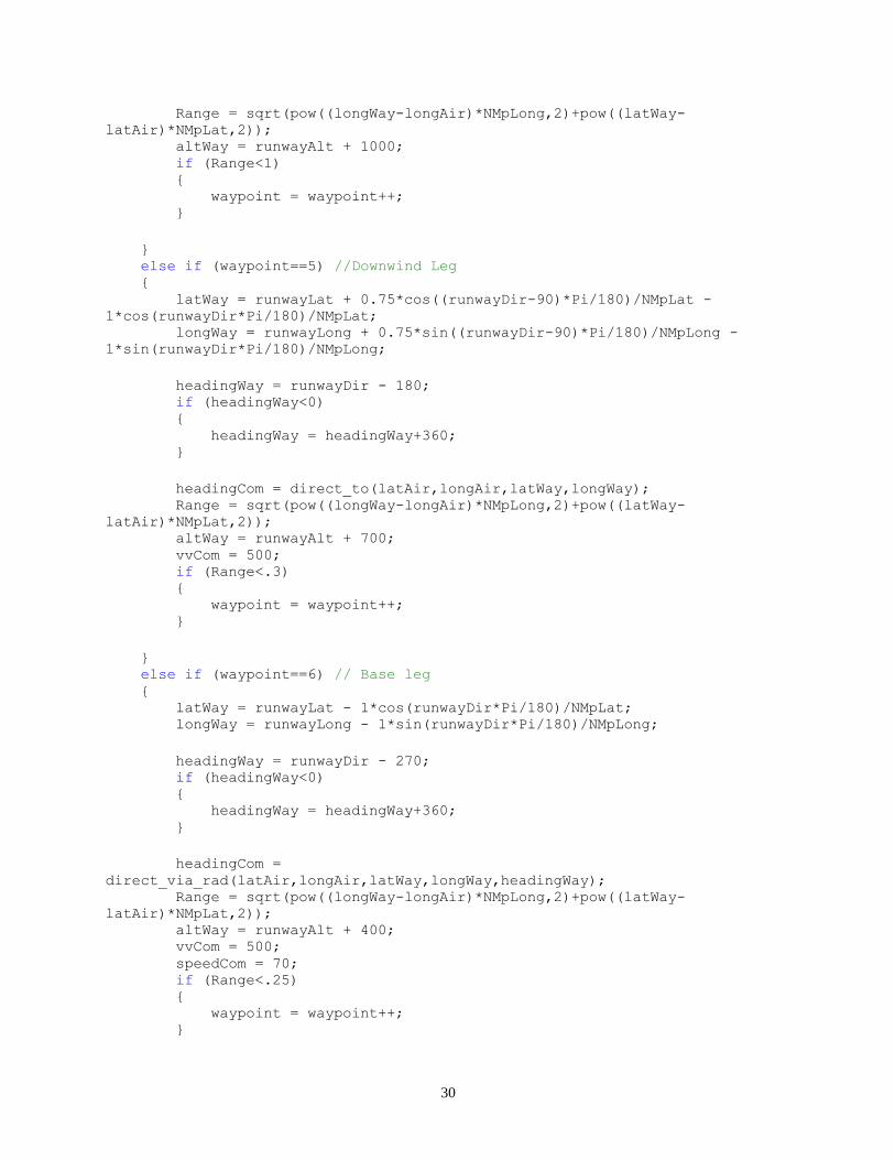
C. Traffic Pattern Navigation The traffic pattern is defined for this project as seen in Fig 3. The aircraft is initially at the beginning of the
runway (1). The aircraft accelerated to rotation speed and starts an upwind climb (2). After reaching 500 ft AGL (3),
the aircraft turns onto the cross wind leg, continuing a climb to a traffic pattern altitude of 1000ft AGL. The aircraft
turns parallel with the runway (4) onto a downwind leg three fourths of a mile laterally from the runway centerline.
When the aircraft is a beam of the landing point (5), it begins a 500ft/min decent. The aircraft turns onto the base leg
when the touchdown point is 45° behind the aircraft (6). It continues the descent and turns to line up with the runway
of the final leg (7). The aircraft stays on a 500ft/min glideslope until it is 100ft AGL (8). At this point it begins to
flare. The aircraft touches down (9) and rolls to a stop.

9
Figure 3 - Standard left handed traffic pattern
The traffic pattern can be defined mathematically by vectors pointing from the touchdown point on the runway.
The vectors are rotated by the runway’s orientation with respect to true north ψrunway. Equations 6 and 7 calculate the
latitude and longitude of a point some distance x and y from the starting location. See Fig. 4.
Δ𝑙𝑜𝑛𝑔 = 𝑥𝑠𝑖𝑛 𝜓𝑟𝑢𝑛𝑤𝑎𝑦 − 𝑦𝑐𝑜𝑠 𝜓𝑟𝑢𝑛𝑤𝑎𝑦 (6)
Δ𝑙𝑎𝑡 = 𝑥𝑐𝑜𝑠 𝜓𝑟𝑢𝑛𝑤𝑎𝑦 + 𝑦𝑠𝑖𝑛(𝜓𝑟𝑢𝑛𝑤𝑎𝑦 ) (7)
Figure 4 - Runway heading axis rotation
Ψrunway

10
The waypoints are input into the mission controller by distances from the runway threshold as defined by Table
1.
Table 1 - Waypoints defined in mission controller
Waypoint Δx Δy ΔAltitude Function Called
Takeoff (2) N/A N/A 100ft Direct To Waypoint
Turn Crosswind (3) 1.5 0 1000ft Direct To Waypoint
Turn Downwind (4) 1.5 .75 1000ft Direct To Waypoint
Beginning of Decent (5) 0 .75 1000ft Direct To Waypoint
Turn Base (6) -1.0 .75 700ft Direct To Waypoint
Turn Final (7) -1.0 0 400 ft Direct To Waypoint
Runway Threshold (8) 0 0 100 ft To Waypoint Via Radial, Glideslope
Flare 1.5 0 0 ft To Waypoint Via Radial, Flare
At several points during the mission, the controller has to decide between possible options. When the mission
controller is first started, it determines whether it is flying or not. Currently the simulator has two possible starting
locations: flying or at the start of a runway. If the aircraft is flying, the mission controller will fly the aircraft to the
mission airport. If the aircraft is at the start of a runway, it will takeoff and fly the pattern. If it took off from another
airport, it will fly to and land at the mission airport. After the aircraft has landed, it will determine if there is enough
room to takeoff. If there is it will perform a touch-and-go, otherwise it will stop. A decision flow chart is shown in
Fig 5. The s-function source code for the mission controller is shown in Appendix F.
Figure 5 - Decision flow chart

11
IV. Autopilot Performance
In order for the autopilot to be effective at maneuvering the aircraft in the traffic pattern, the autopilot must
provide adequate and predictable responses to commands. Each autopilot function is tested with a step command.
Figure 6 shows the altitude response of the aircraft given a command to change altitude from 1,000ft to 2,000ft at a
maximum vertical velocity of 8.3 ft/s (500 ft/m).
Figure 6 - Altitude response with command airspeed and heading held constant

12
The aircraft quickly establishes a vertical velocity of 8.3 ft/s with a slight overshoot to 9.5 ft/s. The vertical
velocity ramps down at 50 ft below the target altitude as designed. It takes approximately 20 seconds to transition
from the climb to the target altitude.
Figure 7 shows the response of the aircraft given a command to accelerate to 120 kias from 70 kias.
Figure 7 - Airspeed response with commanded altitude and heading held constant
At full throttle, the airspeed increases as quickly as excess power will allow. This results in the decreasing
acceleration as the airspeed increases. The airspeed oscillates around the target airspeed within ±2 kias and is slowly
damped out. This oscillation is most likely caused by the lag time inherent in the time it takes a commanded throttle
change to respond.
Figure 8 shows the aircraft response to a commanded 180 degree right turn at a 20 degree bank angle.

13
Figure 8 - Heading response with commanded altitude and airspeed held constant
The aircraft responds quickly to its commanded heading change by rolling to its maximum bank angle. The
constant bank turn produces a constant change in heading seen in Fig. 8. The aircraft ramps down the bank angle at a
heading that is half the bank angle away from the targeted heading. The roll out takes five seconds.
To control the aircraft during normal maneuvering, the autopilot will need to make changes to the altitude,
airspeed, and heading simultaneously. Thus a test was performed in a way which the three commands conflicted
with each other. A command was given for the aircraft to accelerate from 70 kts to 120 kts, climb from 1000ft to
1500ft, and turn 180 degrees to the right. The results of the test are seen in Fig 8.

14
Figure 9 - Simultaneous altitude, airspeed, and heading response at a maximum bank angle of 20 degrees

15
The aircraft is able to respond to all three commands simultaneously without a significant loss in performance.
The vertical velocity responds quickly to the commanded increase in altitude but overshoots the maximum vertical
velocity to a higher degree then when it did during the altitude only test. This can be attributed to the increase in
airspeed that causes the aircraft to pitch up. The trim cannot correct for the change in airspeed quick enough since it
has a time constant of 20 seconds. The airspeed plot in Fig. 9 shows how excess power decreases on the aircraft as it
tries to climb and accelerate at the same time. It is not until it reaches its target altitude around 55 seconds when the
aircraft is able to finish accelerating to 120 kts. The heading response has the same performance as it did in the
heading only test, but the change in bank angles caused fluctuations in vertical velocity as seen at 45 seconds. Even
with these small off performance responses, the autopilot is able to perform the mission required by the mission
controller.
V. Autonomous Mission Controller Performance
The autonomous controller was first run with the aircraft positioned stationary at the beginning of the runway.
The controller was able to recognize this position and proceed to takeoff from the runway. Following the waypoints
that were listed in Table 1, the aircraft flew the traffic pattern and performed continuous touch-and-gos. The
airplane’s ground path is shown in Fig. 10 overlaid on a satellite image of the airport.
Figure 10 - Aircraft ground path overlaid on San Luis Obispo County Regional Airport with ground path
over airport removed for clarity

16
The aircraft precisely follows the traffic pattern from takeoff to crosswind and downwind legs. The base leg to
final leg are rounded as the aircraft attempts to intercept the path lining up with the runway. After lining up with the
runway, the aircraft follows the centerline of the runway until it lands. The altitude profile of the traffic pattern is
shown in Fig. 11.
Figure 11 - Altitude profile during traffic pattern
After takeoff the aircraft maintains a constant rate of climb until it reaches traffic pattern altitude 1,000 ft above
the airport elevation. The aircraft flies at traffic pattern altitude until it reaches the point that is abeam the touchdown
point. It then begins a 500 ft/m decent. When the aircraft turns for its final leg it changes from a constant decent rate
to a variable rate. This variable rate tries to intercept a path that reaches the runway touchdown point at 500 ft/m.
Since the aircraft is higher than this path when it begins the final leg, it increases the decent rate to intercept. At
100ft above the runway, the controller switches from the glide slope function to the flare function that decreases the
decent rate as the aircraft approaches the ground. A rule of thumb for general aviation aircraft in the traffic pattern is

17
that it should take two minutes from beginning of decent to touchdown by descending at 500 ft/m. The RV-7 begins
its decent at 160 seconds and touches down at 290 seconds, two minutes and 10 seconds later.
The autonomous controller was then tested with the aircraft initially flying at an off airport location. For this test,
the aircraft was placed over Oceano County Airport, 8.5 nautical miles from San Luis Obispo County Regional
Airport. The aircraft flew directly to a point at the start of a left 45 degree entry into the pattern and proceeded to
successfully land at the airport as seen in the ground path in Fig 12.
Figure 12 - Left 45 degree entry into traffic pattern
The autonomous controller was also tested at Los Angeles International Airport and San Francisco International
Airport by inputting new landing point GPS coordinates, altitudes, and runway directions for the airports. The
aircraft has similar results as seen at San Luis Obispo County Regional Airport. It is clear though from these tests
that the mission controller is not robust enough to cover missions outside the airport airspace since it does not have
terrain avoidance. At one point the aircraft flew directly through a hill to get to a waypoint. This did not change the

18
outcome of the mission since crash detection was turned off. Future missions would need to be planned specifically
to avoid object on the ground. Also, the mission controller is developed specifically for the RV-7 modeled the
motion flight simulator. An attempt to use another aircraft model will most likely result in failure.
VI. Conclusion
Both the primary and secondary objective of the project were accomplished by demonstrating that the aircraft
can fly a traffic pattern at various airport and enter the traffic pattern from any flying location outside the airport.
The autopilot was developed separate from the mission controller such it could be programmed by the pilot or by a
different mission controller. This flexibility increases the value of the autopilot to future users of the motion flight
simulator. The mission controller can be modified to achieve different missions by creating new waypoints. The
Direct to Waypoint, To Waypoint Via Radial, Glide Slope, and Flare functions can be used in the future to achieve
different mission objectives. Certain functions such as ground avoidance can be added to increase the robustness of
the mission controller.

19
Appendix A: Motion Flight Simulator

20
Appendix B: Autopilot and Mission Controller
21
Appendix C: Altitude Hold Autopilot

22
Appendix D: Heading Hold Autopilot

23
Appendix E: Airspeed Hold Autopilot

24
Appendix F: Mission Controller S-Function //*********************************************************************** // AUTHOR(S): Andrew Anderson [AMA] // DATE: 04/26/2010 // // Copyright (c) ALL RIGHTS RESERVED // // REVISION HISTORY: // // REV AUTHOR DATE DESCRIPTION // 0 AMA 04/26/2010 File Created // 1 AMA 04/27/2010 Fly Direct and Fly to via radial funtions
created // 2 AMA 05/04/2010 Plane flys racetrack pattern // 3 AMA 05/05/2010 Racetrack defined by runway location and
direction // 4 AMA 05/06/2010 GLideslope and flare function added // 5 AMA 05/07/2010 Landing and Takeoff legs defined, aircraft
flies left traffic pattern with touch-and-gos // // S-mex: See simulink/src/sfuntmpl.doc // // Copyright (c) 1990-1998 by The MathWorks, Inc. All Rights Reserved. // $Revision: 1.3 // //***********************************************************************
#define S_FUNCTION_NAME rv7_ai #define S_FUNCTION_LEVEL 2
#include "MatrixMath.h" #include "simstruc.h" #include "math.h"
double direct_to(double LatAir, double LongAir, double LatWay, double
LongWay); double direct_via_rad(double LatAir, double LongAir, double LatWay, double
LongWay, double Rad); double glideslope(double LatAir, double LongAir, double LatWay, double
LongWay, double AltAir, double AltCom, double AirSpeed); double flare(double LatAir, double LongAir, double LatWay, double LongWay,
double AltAir, double AltCom, double AirSpeed); // Matlab required Functions // Function: mdlIntializeSizes
================================================ static void mdlInitializeSizes(SimStruct *S) {
// Number of parameters to type in, usually // a file name or a number of time steps, ect. // Second parameter is the number of inputs. ssSetNumSFcnParams(S, 0);
// Check for Simulink port matching errors if (ssGetNumSFcnParams(S) != ssGetSFcnParamsCount(S))

25
{ printf("S Function Parameter Error.\n"); return; };
//**************************// // Initilize Input Ports // //**************************// // Set the number of input ports. INPUT PORTS = // Log the error. if (!ssSetNumInputPorts(S, 4)) { printf("Set Number Input Ports Error.\n"); return; };
// Input Port 0, 1 number ssSetInputPortWidth(S, 0, 3); ssSetInputPortWidth(S, 1, 3); ssSetInputPortWidth(S, 2, 3); ssSetInputPortWidth(S, 3, 1);
// This command must be in here, // The second value is the port number // The last value is 1. // for(int i = 0;i<11;i++) ssSetInputPortDirectFeedThrough(S,0,1); ssSetInputPortDirectFeedThrough(S,1,1); ssSetInputPortDirectFeedThrough(S,2,1); ssSetInputPortDirectFeedThrough(S,3,1);
//**************************// // Initilize Output Ports // //**************************// // very much like set input ports if (!ssSetNumOutputPorts(S,7)) { printf("Set Num Output Ports Error\n"); return; }
// Output Port number 0, 1 number ssSetOutputPortWidth(S, 0, 1); ssSetOutputPortWidth(S, 1, 1); ssSetOutputPortWidth(S, 2, 1); ssSetOutputPortWidth(S, 3, 1); ssSetOutputPortWidth(S, 4, 1); ssSetOutputPortWidth(S, 5, 1); ssSetOutputPortWidth(S, 6, 1); //debugging output
//**********************//

26
// No feed through!!! // //**********************//
// Number of sample times s has. One is good. ssSetNumSampleTimes(S, 1);
ssSetNumPWork(S, 1);
// Exception free code is currently disabled. // Needed to increase speed ssSetOptions(S, SS_OPTION_EXCEPTION_FREE_CODE);
// Initilize values here };
// Function: mdlInitializeSampleTimes
========================================= static void mdlInitializeSampleTimes(SimStruct *S) { //printf("aero sample\n"); ssSetSampleTime(S, 0, CONTINUOUS_SAMPLE_TIME); ssSetOffsetTime(S, 0, FIXED_IN_MINOR_STEP_OFFSET); //printf("aero sample f\n"); }
#define MDL_START #if defined(MDL_START)
// Function: mdlStart
========================================================= static void mdlStart(SimStruct *S) {
} #endif // MDL_START
// Function: mdlOutputs
======================================================= static void mdlOutputs(SimStruct *S, int_T tid) {
InputRealPtrsType posPtrs = ssGetInputPortRealSignalPtrs(S,0); // Input InputRealPtrsType velPtrs = ssGetInputPortRealSignalPtrs(S,1); InputRealPtrsType anglePtrs = ssGetInputPortRealSignalPtrs(S,2); InputRealPtrsType waypointPtrs = ssGetInputPortRealSignalPtrs(S,3);
Vector3 pos; pos.x = *posPtrs[0]; pos.y = *posPtrs[1]; pos.z = *posPtrs[2];
Vector3 vel;

27
vel.x = *velPtrs[0]; vel.y = *velPtrs[1]; vel.z = *velPtrs[2];
Vector3 angle; angle.x = *anglePtrs[0]; angle.y = *anglePtrs[1]; angle.z = *anglePtrs[2];
int waypoint = *waypointPtrs[0];
real_T *headingout = ssGetOutputPortRealSignal(S,0); //
Outputs real_T *bankout = ssGetOutputPortRealSignal(S,1); real_T *ALTout = ssGetOutputPortRealSignal(S,2); real_T *VVout = ssGetOutputPortRealSignal(S,3); real_T *IASout = ssGetOutputPortRealSignal(S,4); real_T *waypointout = ssGetOutputPortRealSignal(S,5); real_T *debug = ssGetOutputPortRealSignal(S,6);
double latAir = pos.x; double longAir = pos.y; double altAir = pos.z;
//KSBP RWY29 double const runwayLat = 35.233729; double const runwayLong = -120.634285; double const runwayDir = 290.9 + 13.9; double const runwayAlt = 200;
double latWay; //Waypoint location and intercept direction double longWay; double altWay = runwayAlt + 1000; //TPA double headingWay; //Radial "from" waypoint. The direction the plane
wants to intercept double Range = 666;
double headingCom; double vvCom = 1000; double speedCom = 80; double bankCom = 25;
double const Pi = 3.14159265; double const NMpLat = 59.91; double const NMpLong = 49.15;
if ((waypoint==0)&&(vel.x>40)&&(altAir>400)) { waypoint=10; }

28
if (waypoint==0) //takeoff { headingCom = runwayDir; vvCom = 1000; speedCom = 80; if (vel.x<60) { altWay = altAir; } else { altWay = runwayAlt + 1000; } if (altAir>runwayAlt+100) { waypoint = 2; }
} else if (waypoint==10) // To entry into Left 45 { latWay = runwayLat + 0.75*cos((runwayDir-90)*Pi/180)/NMpLat +
.5*cos(runwayDir*Pi/180)/NMpLat + 2*cos((runwayDir-45)*Pi/180)/NMpLat; longWay = runwayLong + 0.75*sin((runwayDir-90)*Pi/180)/NMpLong +
.5*sin(runwayDir*Pi/180)/NMpLong + 2*sin((runwayDir-45)*Pi/180)/NMpLong; headingCom = direct_to(latAir,longAir,latWay,longWay); Range = sqrt(pow((longWay-longAir)*NMpLong,2)+pow((latWay-
latAir)*NMpLat,2)); altWay = runwayAlt + 2000; speedCom = 120; if (Range<.33) { waypoint = waypoint++; //to pattern insertion point }
} else if (waypoint==11) // Left 45 insertion point { latWay = runwayLat + 0.75*cos((runwayDir-90)*Pi/180)/NMpLat +
.5*cos(runwayDir*Pi/180)/NMpLat; longWay = runwayLong + 0.75*sin((runwayDir-90)*Pi/180)/NMpLong +
.5*sin(runwayDir*Pi/180)/NMpLong;
headingWay = runwayDir - 225; if (headingWay<0) { headingWay = headingWay+360; }
headingCom =
direct_via_rad(latAir,longAir,latWay,longWay,headingWay); Range = sqrt(pow((longWay-longAir)*NMpLong,2)+pow((latWay-
latAir)*NMpLat,2)); altWay = runwayAlt + 1000; if (Range<.1)

29
{ waypoint = 4; //to abeam numbers }
} else if (waypoint==2) //Upwind leg { latWay = runwayLat + 1.5*cos(runwayDir*Pi/180)/NMpLat; longWay = runwayLong + 1.5*sin(runwayDir*Pi/180)/NMpLong; headingWay = runwayDir; headingCom = direct_to(latAir,longAir,latWay,longWay); Range = sqrt(pow((longWay-longAir)*NMpLong,2)+pow((latWay-
latAir)*NMpLat,2)); if (Range<.33) { waypoint = waypoint++; }
} else if (waypoint==3) // Crosswind leg { latWay = runwayLat + 1.5*cos(runwayDir*Pi/180)/NMpLat +
0.75*cos((runwayDir-90)*Pi/180)/NMpLat; longWay = runwayLong + 1.5*sin(runwayDir*Pi/180)/NMpLong +
0.75*sin((runwayDir-90)*Pi/180)/NMpLong;
headingWay = runwayDir - 90; if (headingWay<0) { headingWay = headingWay+360; }
headingCom = direct_to(latAir,longAir,latWay,longWay); Range = sqrt(pow((longWay-longAir)*NMpLong,2)+pow((latWay-
latAir)*NMpLat,2)); if (Range<.33) { waypoint = waypoint++; }
} else if (waypoint==4) // Abeam numbers { latWay = runwayLat + 0.75*cos((runwayDir-90)*Pi/180)/NMpLat -
1*cos(runwayDir*Pi/180)/NMpLat; longWay = runwayLong + 0.75*sin((runwayDir-90)*Pi/180)/NMpLong -
1*sin(runwayDir*Pi/180)/NMpLong; headingWay = runwayDir - 180;
if (headingWay<0) { headingWay = headingWay+360; }
headingCom = direct_to(latAir,longAir,latWay,longWay);
30
Range = sqrt(pow((longWay-longAir)*NMpLong,2)+pow((latWay-
latAir)*NMpLat,2)); altWay = runwayAlt + 1000; if (Range<1) { waypoint = waypoint++; }
} else if (waypoint==5) //Downwind Leg { latWay = runwayLat + 0.75*cos((runwayDir-90)*Pi/180)/NMpLat -
1*cos(runwayDir*Pi/180)/NMpLat; longWay = runwayLong + 0.75*sin((runwayDir-90)*Pi/180)/NMpLong -
1*sin(runwayDir*Pi/180)/NMpLong;
headingWay = runwayDir - 180; if (headingWay<0) { headingWay = headingWay+360; }
headingCom = direct_to(latAir,longAir,latWay,longWay); Range = sqrt(pow((longWay-longAir)*NMpLong,2)+pow((latWay-
latAir)*NMpLat,2)); altWay = runwayAlt + 700; vvCom = 500; if (Range<.3) { waypoint = waypoint++; }
} else if (waypoint==6) // Base leg { latWay = runwayLat - 1*cos(runwayDir*Pi/180)/NMpLat; longWay = runwayLong - 1*sin(runwayDir*Pi/180)/NMpLong;
headingWay = runwayDir - 270; if (headingWay<0) { headingWay = headingWay+360; }
headingCom =
direct_via_rad(latAir,longAir,latWay,longWay,headingWay); Range = sqrt(pow((longWay-longAir)*NMpLong,2)+pow((latWay-
latAir)*NMpLat,2)); altWay = runwayAlt + 400; vvCom = 500; speedCom = 70; if (Range<.25) { waypoint = waypoint++; }

31
} else if (waypoint==7) // Final { altWay = runwayAlt; //Lower then runway altitude to ignore flaring
effects of autopilot latWay = runwayLat; longWay = runwayLong;
headingWay = runwayDir; if (headingWay<0) { headingWay = headingWay+360; }
headingCom =
direct_via_rad(latAir,longAir,latWay+cos(runwayDir*Pi/180)/NMpLat,longWay+sin
(runwayDir*Pi/180)/NMpLong,headingWay-5.4); bankCom = 25; speedCom = 70; if ((altAir-altWay)>50) { vvCom =
glideslope(latAir,longAir,latWay,longWay,altAir,altWay,vel.x); } else if ((altAir-altWay)<5) { vvCom = flare(latAir,longAir,latWay,longWay,altAir,altWay,vel.x); speedCom = 0; } else { vvCom = flare(latAir,longAir,latWay,longWay,altAir,altWay,vel.x); } Range = sqrt(pow((longWay-longAir)*NMpLong,2)+pow((latWay-
latAir)*NMpLat,2)); if ((Range<.25)&&(altAir>runwayAlt+200)) { waypoint = 2; //Go around } else if (vel.x<40) { waypoint = 0; //Takeoff again }
} else { headingWay = 0; headingCom = 0; waypoint = 0; } //double headingCom =
direct_via_rad(latAir,longAir,latWay,longWay,headingWay);
32
Range = sqrt(pow((longWay-longAir)*NMpLong,2)+pow((latWay-
latAir)*NMpLat,2)); //60 nmiles per latitude, 60cos(lat(rads)) nmiles per
long
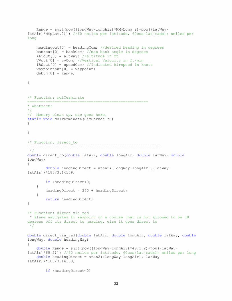
headingout[0] = headingCom; //desired heading in degrees bankout[0] = bankCom; //max bank angle in degrees ALTout[0] = altWay; //altitude in ft VVout[0] = vvCom; //Vertical Velocity in ft/min IASout[0] = speedCom; //Indicated Airspeed in knots waypointout[0] = waypoint; debug[0] = Range;
}
/* Function: mdlTerminate
===================================================== * Abstract: */ // Memory clean up, etc goes here. static void mdlTerminate(SimStruct *S) {
}
/* Function: direct_to
=========================================================== */ double direct_to(double latAir, double longAir, double latWay, double
longWay) { double headingDirect = atan2((longWay-longAir),(latWay-
latAir))*180/3.14159;
if (headingDirect<0) { headingDirect = 360 + headingDirect; } return headingDirect; }
/* Function: direct_via_rad * Plane navigates to waypoint on a course that is not allowed to be 30
degrees off its direct to heading, else it goes direct to */
double direct_via_rad(double latAir, double longAir, double latWay, double
longWay, double headingWay) { double Range = sqrt(pow((longWay-longAir)*49.1,2)+pow((latWay-
latAir)*60,2)); //60 nmiles per latitude, 60cos(lat(rads)) nmiles per long double headingDirect = atan2((longWay-longAir),(latWay-
latAir))*180/3.14159;
if (headingDirect<0)

33
{ headingDirect = 360 + headingDirect; }
double headingCom; double courseDev;
if ((headingDirect>headingWay)&&((headingDirect-headingWay)<30)) { courseDev = Range*(headingDirect-headingWay)*3.14159/180; return (headingWay + 50*pow(courseDev/(courseDev+.025),2)+1); } else if ((headingDirect<headingWay)&&((headingWay-headingDirect)<30)) { courseDev = Range*(headingWay-headingDirect)*3.14159/180; return (headingWay - 50*pow(courseDev/(courseDev+.025),2)-1); } else if ((headingDirect>headingWay)&&((headingDirect-headingWay)>330)) { courseDev = Range*(headingWay-headingDirect+360)*3.14159/180; return (headingWay - 50*pow(courseDev/(courseDev+.025),2)-1); } else if ((headingDirect<headingWay)&&((headingWay-headingDirect)>330)) { courseDev = Range*(headingDirect-headingWay+360)*3.14159/180; return (headingWay + 50*pow(courseDev/(courseDev+.025),2)+1); } else { return headingDirect; } }
double glideslope(double latAir, double longAir, double latWay, double
longWay, double altAir, double altCom, double airSpeed) { double Range = sqrt(pow((longWay-longAir)*49.1,2)+pow((latWay-
latAir)*60,2))*6000; //ft, 60 nmiles per latitude, 60cos(lat(rads)) nmiles
per long airSpeed = airSpeed*1.68781; //kts to ft/s double desired_vv = ((altAir-altCom)*airSpeed/(Range+500))*60; //vertical
velocity in ft/s
if ((2*desired_vv - 500)-100>0) { return (2*desired_vv - 500)-100; } else { return 0.01; }
}

34
double flare(double latAir, double longAir, double latWay, double longWay,
double altAir, double altCom, double airSpeed) { double Range = sqrt(pow((longWay-longAir)*49.1,2)+pow((latWay-
latAir)*60,2))*6000; //ft, 60 nmiles per latitude, 60cos(lat(rads)) nmiles
per long airSpeed = airSpeed*1.68781; //kts to ft/s
return fabs(((altAir-altCom)/(altAir-altCom+50))*500 + 30); //vertical
velocity in ft/s }
#ifdef MATLAB_MEX_FILE /* Is this file being compiled as a MEX-file? */ #include "simulink.c" /* MEX-file interface mechanism */ #else #include "cg_sfun.h" /* Code generation registration function */ #endif

35
References
[1] Clough, Bruce T., “Unmanned Aerial Vehicles: Autonomous Control Challenges, a Researcher’s Perspective,” AIAA 2003-
6504, 2003.
[2] Tolvtvar, Jason A., “Simulation of Autonomous Landing,” California Polytechnic State University Senior Project, 2005.
[3] Stevens, Brian L., Aircraft Control and Simulation, 2nd ed. John Wiley & Sons, New Jersey, 2003, Ch 4.