autonomous environmental buoy/regatta...
TRANSCRIPT

Instituto Superior de Engenharia do Porto
Departamento de Engenharia Eletrotécnica Rua Dr. António Bernardino de Almeida, 431, P-4200-072 Porto
AUTONOMOUS ENVIRONMENTAL BUOY/REGATTA BEACON
TELEMETRY AND CONFIGURATION
Autonomous Systems Laboratory (LSA) Erasmus Project/Internship Thesis
MSc. in Electrical and Computers Engineering
Hendrik Verschelde
Supervisors: Paulo Ferreira, Pedro Barbosa Guedes, Benedita Malheiro, Manuel Silva
January 2014
Academic Year: 2013-2014

ii

Acknowledgement I would like to take this opportunity to thank all the people and institutions who were involved during
the project. Firstly I'm very grateful for receiving the opportunity by the Kaho Sint-Lieven Ghent and
the Instituto Superior de Engenharia do Porto, to fulfil my thesis at the Laboratório de Sistemas
Autónomos (LSA) of the Instituto Superior de Engenharia do Porto (ISEP). It was a great experience
and I had a great time. A special thank should be offered to Mrs. Benedita Malheiro, Mr. Paulo Ferreira, Mr. Manuel Silva and
Mr. Pedro Guedes for holding the weekly meetings, giving me a lot of advice, bringing me in contact
with other peoples and specially for all the knowledge they taught me. Without these people and
there wisdom it would have been hard to realize the project to this point. I want to express my
gratitude ones more for holding the weekly meetings, since they gave me the needed drive to keep
the work going.
Especially I want to mention Mrs. Benedita Malheiro for giving me the change to work at this project.
Without her involvement and interest in the project, I wouldn't accomplish as much as I have now.
Also thank you for borrowing me your USB-hub.
Simultaneously I'm thankful to Mr. Paulo Ferreira who was a great help in the software part of the
project. This by helping me and for letting me use his BeagleBone Black and the accompanying book:
“Bad to the Bone”.
I also want to show my gratitude ones again to all the supervisors for reading my report and the
resulting feedback.
Last but not least, I would like to thank Mr. Pedro Rocha for ordering the necessary components and
for providing me the crossed cable.
iii

Abstract Nowadays there is much emphasis put on monitoring and registration of as many environmental
aspects as possible; this mostly to improve the security or for research purposes. Since the world
mostly consists out of water and because of global warming, monitoring the water is crucial. One of the methods to monitor the water is using buoys. The market is not exhausted yet and it does
need a breath of fresh air. These are just some of the reasons why the project: “Autonomous
Environmental Buoy/Regatta Beacon” was started last year.
The buoy designed in this project has two major applications: collection of weather data and
assistance in autonomous sailing boat regattas. Last year a group of four students already started this project. Their objectives were: the design and
construction of the buoy and a general research about the necessary components in order to buy the
most suitable components for the application. In contrast to the previous group who chose this project to realize their European Project Semester
[1], my colleague and I have chosen this project to accomplish our thesis. The project was divided into two main parts: the data logging part and the telemetry and
configuration part. This report will handle about the telemetry and configuration part. The group of last year chose one main controlling unit to accomplish the different tasks. This year
there was chosen for two different controlling units, which actually determines the two different parts
of the project. The first control unit works as the interface for multiple sensors that collects and stores
the data in the memory, which includes the data logging part. The other control unit does the
configuration and downloading of data from the memory to send it then to the requested base station,
which includes also the telemetry and configuration part. Given that the provided control unit has to be used for the data logging part, the first task was to do
research about different control units in order to choose the most suitable one. The control unit needs
to support multitasking; a control unit with an own operating system was therefore recommended.
The second task was to choose and reconfigure the operating system which should be used. The third
task was to determine the used wireless technique to communicate with a base station. After
choosing the wireless technique there was a comparison study about the different possible wireless
communication modules. After this research work, the development of the telemetry system was the
final task in this part. There was also a joint work: the design and development of a self-defined protocol; this protocol
defines the transfer of data and instructions between the two control units. Finally the purpose is to have an autonomous buoy that collects data, saves this data and finally
exchanges it with the requested base stations. The buoy combines two major and significant
applications, i.e. data collection and assistance in regattas; this makes it the first of it's type. The buoy has unfortunately two limitations. First of all, it can only hold up a total weight of around 40
kg. Secondly, it can only be used in a river or near the shore, it can't be used on the open sea or the
ocean, this due to the distance limitation of the chosen wireless communication technique.
iv

Table of contents
Acknowledgement .......................................................................................................................................i Abstract ...................................................................................................................................................... iv
Table of contents ..........................................................................................................................................v
List of illustrations ....................................................................................................................................... vii List of tables ............................................................................................................................................... vii Glossary ...................................................................................................................................................... xi 1. Introduction ............................................................................................................................................. 2
1.1 Presentation ................................................................................................................................ 2
1.2 Motivation .................................................................................................................................... 2
1.3 General Information ................................................................................................................... 2
1.4 Project description ...................................................................................................................... 3
1.5 Objectives.................................................................................................................................... 4
1.5.1 General objective ................................................................................................................. 4
1.5.2 Objectives within the telemetry and configuration part ..................................................... 4
1.6 Requirements ................................................................................................................................ 5
2. State of the Art ........................................................................................................................................ 6
2.1 Introduction ................................................................................................................................... 6
2.1.1 Hull ........................................................................................................................................ 6
2.1.2 Available Equipment ............................................................................................................. 6
2.1.3 Competitors ........................................................................................................................... 8
2.2 Master Controller ...................................................................................................................... 13
2.2.1 Introduction ......................................................................................................................... 13
2.2.2 BeagleBone Black ................................................................................................................ 13
2.2.3 Raspberry Pi ........................................................................................................................ 15
2.2.2 The STM32F3 Discovery development board................................................................... 17
2.2.3 Comparison study ............................................................................................................... 18
2.2.4 General conclusion ............................................................................................................. 18
2.3 Communication Technique ...................................................................................................... 20
2.3.1 Introduction ......................................................................................................................... 20
2.3.2 Related systems ................................................................................................................. 20
2.3.3 Bluetooth ............................................................................................................................. 21
2.3.4 Wi-Fi .................................................................................................................................... 21
2.3.4 GSM..................................................................................................................................... 22
2.3.5 Comparing the specifications ............................................................................................. 22
2.3.6 Conclusion ........................................................................................................................... 22
2.4 Wi-Fi module ............................................................................................................................. 23
2.4.1 Introduction ......................................................................................................................... 23
2.4.2 Most common used Wi-Fi modules in the water sports ................................................... 23
2.5 Working environment ............................................................................................................... 28
v

2.5.1 Working directly on the BeagleBone Black board ............................................................ 28
2.5.2 Working virtually ................................................................................................................. 29
2.5.3 Working from a second partition on an internal hard-drive ............................................. 29
2.5.4 Working from a memory stick or DVD ............................................................................... 30
2.5.5 Working from an external hard-drive ................................................................................ 31
3. Project Development ....................................................................................................................... 32
3.1 Components ............................................................................................................................... 32
3.2 Protocol ...................................................................................................................................... 35
3.2.1 Introduction ......................................................................................................................... 35
3.2.2 General overview ............................................................................................................... 37
3.2.3 Protocol Diagrams................................................................................................................ 46
3.2.4 Implementation .................................................................................................................... 51
3.3 Communication .......................................................................................................................... 51
3.3.1 Introduction ......................................................................................................................... 51
3.3.2 Communication with the STM32F3 Discovery development board ................................. 51
3.3.3 Communication with the the Wi-Fi module ....................................................................... 66
4. Project Development Tools .............................................................................................................. 71
4.1 Getting Started with BeagleBone & BeagleBone Black ........................................................ 71
4.1.1 Introduction ......................................................................................................................... 71
4.1.2 Getting Started manual [50] ............................................................................................. 71
4.2 Installing Linux on an external hard-drive ............................................................................. 79
4.2.1 Introduction ......................................................................................................................... 79
4.2.2 The manual ......................................................................................................................... 79
4.3 Installing Eclipse on Linux ........................................................................................................ 90
4.3.1 Introduction .............................................................................................................................. 90
4.3.2 Installation guide ....................................................................................................................... 90
4.4 Compiling and running a Java program on Linux .................................................................. 94
4.4.1 Introduction ......................................................................................................................... 94
4.4.2 Manual ................................................................................................................................. 94
4.5 Making a backup from the home-folder on Linux .................................................................. 96
4.5.1 Introduction ......................................................................................................................... 96
4.5.2 Solutions ............................................................................................................................. 96
5. Conclusions ....................................................................................................................................... 98
5.1 Discussion .................................................................................................................................. 98
5.2 Future Developments ............................................................................................................... 99
5.2.1 Protocol ............................................................................................................................... 99
5.2.2 BeagleBone Black board .................................................................................................... 99
5.2.3 Communication ................................................................................................................... 99
Bibliography ........................................................................................................................................... 100
Appendices ............................................................................................................................................ 103
vi

List of Figures
Figure 1-1 Example of a buoy as marker [2] ......................................................................................... 3
Figure 1-2 Example of a measuring buoy [3] ........................................................................................ 3
Figure 1-3 Existing hull ......................................................................................................................... 3
Figure 1-4 Existing stainless steel structure ......................................................................................... 3
Figure 2-1 Davis anemometer (wind sensor) [5] ................................................................................... 7
Figure 2-2 CTD sensor ......................................................................................................................... 7
Figure 2-3 Superstar II GNSS receiver [6] ............................................................................................ 7
Figure 2-4 The STM32F3 Discovery development board [8] .......................................................... 8
Figure 2-5 Telemetry in oil and gas industry [10] ............................................................................ 9
Figure 2-6 The Voyager 1, an unmanned spacecraft [11] .............................................................. 9
Figure 2-7 Telemetry in the F1-racing [12] ...................................................................................... 9
Figure 2-8 Wireless weather station [13] ....................................................................................... 10
Figure 2-9 An Autonomous Environmental/Regatta Buoy [3] ........................................................ 10
Figure 2-10 Telemetry in the defense industry [14] ...................................................................... 11
Figure 2-11 Telemetry in the Medicine/Healthcare industry [15] ................................................. 11
Figure 2-12 A whale with an instrumentation tag [16] .................................................................. 12
Figure 2-13 An ankle collar worn by convicts [17] ......................................................................... 12
Figure 2-14 Connectors and switch locations of the BeagleBone Black [19]................................ 14
Figure 2-15 Raspberry Pi connections [22] .................................................................................... 16
Figure 2-16 Raspberry Pi RF-dongle [23] ...................................................................................... 16
Figure 2-17 Wi-Fi Stick [34] ............................................................................................................ 23
Figure 2-18 Turbo Wi-Fi [35] ........................................................................................................... 24
Figure 2-19 Digital Yacht [36] ......................................................................................................... 25
Figure 2-20 Alfa Tube-U(N) [37] ..................................................................................................... 25
Figure 2-21 Wifi Marine [38] ........................................................................................................... 26
Figure 2-22 Alfa AWUSO36H 1000 mW USB Adapter with a 9 dBi Antenna [39] Conclusion .... 27
Figure 2-23 The SR71-USB from Mobility/Ubiquiti Networks [42] ................................................ 28
Figure 2-24 Working directly on the BeagleBone Black board [43] .............................................. 29
Figure 2-25 Running Linux virtually [44] ......................................................................................... 29
Figure 2-26 Using other partitions on an internal hard-drive [45] ................................................ 30
Figure 2-27 Booting Linux from a memory stick [46] ..................................................................... 30
Figure 2-28 WD Elements Portable external hard-drive [47] ....................................................... 31
Figure 3-1 Protocol overview ........................................................................................................... 36
Figure 3-2 Data package for commands and errors/approval ...................................................... 37
Figure 3-3 Data package for data................................................................................................... 38
Figure 3-4 Regatta mode command SOH: $................................................................................... 39
Figure 3-5 Environmental mode command SOH: $ ........................................................................ 40
Figure 3-6 SDC not connected command SOH: $ .......................................................................... 40
Figure 3-7 GNSS not connected command SOH: $ ........................................................................ 40
Figure 3-8 Wrong command, command SOH: $ ............................................................................. 41
vii

Figure 3-9 Wrong data command SOH: $ ....................................................................................... 41
Figure 3-10 Message OK command SOH: $ ................................................................................... 41
Figure 3-11 Stop command SOH: $ ................................................................................................ 42
Figure 3-12 Coordinates command SOH: $ .................................................................................... 42
Figure 3-13 Wind speed command SOH: $ .................................................................................... 43
Figure 3-14 Wind direction command ............................................................................................. 43
Figure 3-15 Depth water command SOH: $ ................................................................................... 44
Figure 3-16 Conductivity water command SOH: $ ......................................................................... 44
Figure 3-17 Temperature water command SOH: $ ........................................................................ 45
Figure 3-18 Requesting data Combination command ID#: 62 ...................................................... 45
Figure 3-19 Protocol Diagram when Command has been sent ..................................................... 46
Figure 3-20 Protocol Diagram when a Mode has been sent ......................................................... 48
Figure 3-21 Protocol Diagram when STM32F3 Discovery doesn't receive a Message OK from the BBB ................................................................................................................................................... 49
Figure 3-22 Protocol Diagram when the BBB doesn't have a connection with the STM32F3 Discovery .......................................................................................................................................... 50
Figure 3-23 Crossed cable ............................................................................................................... 51
Figure 3-24 Lay-out of crossed cable .............................................................................................. 52
Figure 3-25 The Ubuntu Software Center ...................................................................................... 52
Figure 3-26 Serial port Terminal software ..................................................................................... 53
Figure 3-27 Serial Terminal shortcut on Ubuntu Desktop ............................................................. 54
Figure 3-28 Using lsusb command in the terminal before connecting the crossed cable ............ 55
Figure 3-29 Using the lsusb command in the terminal after connecting the crossed cable ........ 56
Figure 3-30 GtkTerm port configuration ......................................................................................... 57
Figure 3-31 port permission denied ................................................................................................ 57
Figure 3-32 Communication between the Linux system and the STM32F3 Discovery board, this by using GtkTerm (testing-command) ............................................................................................. 58
Figure 3-33 Communication between the Linux system and the STM32F3 Discovery board by using GtkTerm (write-command) ..................................................................................................... 59
Figure 3-34 Communication between the Linux system and the STM32F3 Discovery board by using GtkTerm (test-command) ....................................................................................................... 59
Figure 3-35 rxtx-2.1-7-bins-r2 folder .............................................................................................. 61
Figure 3-36 Copying the RXTXcomm.jar into the /jre/lib/ext file of Eclipse .................................. 61
Figure 3-37 Copying librxtxSerial.so into the /jre/lib/[machine type] file of Eclipse ..................... 62
Figure 3-38 Compile/Run Steps and the gnu.io.NoSuchPortException error ............................... 63
Figure 3-39 Running the Java-file in the terminal .......................................................................... 64
Figure 3-40 Flowchart of the program which simulates a serial connection on top of USB, ....... 65
Figure 3-41 Example of a USB hub [49] ......................................................................................... 66
Figure 3-42 Disconnecting from the current internet connection .................................................. 67
Figure 3-43 Connecting to a Wi-Fi internet by using the SR71-USB Wi-Fi module ..................... 68
Figure 3-44 Successfully connection to the Wi-fi internet of LSA .................................................. 69
Figure 4-1 BeagleBone Black LED [50] ........................................................................................... 71
Figure 4-2 BeagleBone Black web server [50] ............................................................................... 72
viii

Figure 4-3 Downloading the latest image [50] ............................................................................... 73
Figure 4-4 Downloading 7-Zip [50] ................................................................................................. 74
Figure 4-5 Running 7-Zip [50] ......................................................................................................... 75
Figure 4-6 decompressing the latest image [50] ........................................................................... 75
Figure 4-7 Writing latest image on the SD card [50] ..................................................................... 76
Figure 4-8 User Boot button [52] .................................................................................................... 77
Figure 4-9 Accepting Licence Agreement ....................................................................................... 80
Figure 4-10 Dropdown list on Universal USB Installer ................................................................... 81
Figure 4-11 Selected Linux Distribution .......................................................................................... 81
Figure 4-12 Selecting a .iso file from the list .................................................................................. 82
Figure 4-13 Creating the Live Linux USB drive .............................................................................. 82
Figure 4-14 Installation process Live Linux USB drive ................................................................... 83
Figure 4-15 Ubuntu welcome screen [51] ...................................................................................... 83
Figure 4-16 Prepare to install Ubuntu [51] .................................................................................... 84
Figure 4-17 Installation type [51] ................................................................................................... 84
Figure 4-18 Standard partition window .......................................................................................... 85
Figure 4-19 Create partition ............................................................................................................ 86
Figure 4-20 Device for boot loader installation .............................................................................. 87
Figure 4-21 Selecting the location [51] .......................................................................................... 87
Figure 4-22 Keyboard layout [51] ................................................................................................... 88
Figure 4-23 Login and password [51] ............................................................................................. 88
Figure 4-24 Ubuntu Installing [51] .................................................................................................. 89
Figure 4-25 Ubuntu installation complete [51] ............................................................................... 89
Figure 4-26 Eclipse download link ................................................................................................... 90
Figure 4-27 Eclipse downloads - mirror selection ........................................................................... 90
Figure 4-28 Saving Eclipse .............................................................................................................. 91
Figure 4-29 Eclipse error ................................................................................................................. 91
Figure 4-30 The JDK folder in the Download folder ....................................................................... 92
Figure 4-31 Final Eclipse folder ....................................................................................................... 93
Figure 4-32 Choosing the location of the workspace folder .......................................................... 93
ix

List of Tables
Table 2-1 Comparison of the BeagleBone and BeagleBone Black [19] ........................................ 13
Table 2-2 Key features of the BeagleBone Black [20] .................................................................. 14
Table 2-3 Comparison of Raspberry Pi Model1 and Model2 [21] ................................................. 15
Table 2-4 Key specification STM32F3 Discovery board [24] ......................................................... 17
Table 2-5 Comparison master controller units [20][21][24] .......................................................... 18
Table 2-6 Comparing the wireless techniques ............................................................................... 22
Table 2-7 Turbo Wi-Fi key specifications [35] ................................................................................ 24
Table 2-8 Digital Yacht key specifications [36] .............................................................................. 24
Table 2-9 Wifi Marine [38] .............................................................................................................. 26
Table 2-10 Alfa AWUSO36H 1000 mW USB Adapter with a 9 dBi Antenna [39] ........................ 26
Table 2-11 the SR71-USB from Mobility/Ubiquiti Networks [40] .................................................. 27
Table 3-1 List of materials (last year) ............................................................................................ 32
Table 3-2 Electronic components .................................................................................................... 33
Table 3-3 List of materials (complete) ............................................................................................ 34
Table 3-4 ID# commands and errors .............................................................................................. 37
Table 3-5 ID# data .......................................................................................................................... 39
Table 3-6 Average current consumption of the SR71-USB Wi-Fi module [40] ............................ 70
Table 4-1 BeagleBone Black software ............................................................................................ 78
Table 4-2 chmod options .................................................................................................................. 96
Table 4-3 chmod numbers ............................................................................................................... 97
x

Glossary Abbreviation Description
Introduction E-compass Electronic compass. EPS
European Project Semester, it's a mixture of “Project Related Courses” and project organized/problem based learning. Students work in international and usually inte- rdisciplinary teams of 3–6 students on their projects, and most of the projects are interdisciplinary.
ISEP Instituto Superior de Engenharia do Porto.
LSA Autonomous Systems Laboratory, R&D Laboratory of ISEP.
PVT Position, Velocity and Time.
State of the Art Accelerometer Is a device that measures acceleration.
AMR Automatic Meter Reading. Bluetooth
Is a wireless technology standard for exchanging data over short distances from fixed and mobile devices, creating personal area networks with high levels of security.
Byte
The byte is a unit of digital information in computing and telecommunications that consists of eight bits. Historically, the byte was the number of bits used to encode a single character of text in a computer and for this reason it is the smallest addressable unit of memory in many computer architectures.
CAN Controller Area Network, type of communication interface.
CEC Consumer Electronics Control, type of communication interface. Compiler
A compiler is a computer program (or set of programs) that transforms source code written in a programming language (the source language) into another computer language (object language).
CPU
Central Processing Unit, is the hardware within a computer that carries out the instructions of a computer program by performing the basic arithmetical, logical, and input/output operations of the system.
Cross compiling Cross compiling is compiling by using a compiler that is capable of creating executable code for a platform other than the one on which the compiler is running.
CTD Conductivity, Temperature and Depth sensor, developed by LSA. DFS
Distributed File Systems, Distributed File System is a set of client and server services that allow an organization using Microsoft Windows servers to organize many distributed server message file shares into a distributed file system.
DSP
Digital Signal Processing is the mathematical manipulation of an information signal to modify or improve it in some way. It is characterized by the representation of discrete time, discrete frequency, or other discrete domain signals by a sequence of numbers or symbols and the processing of these signals.
DRAM Dynamic Random Access Memory, is a type of random-access memory that stores each bit of data in a separate capacitor within an integrated circuit.
DVD Is an optical disc storage format, who offer higher storage capacity than compact discs while having the same dimensions.
E-compass Electronic compass.
EDGE Enhanced Data rates for GSM Evolution, is a digital mobile phone technology that allows improved data transmission rates as a backward-compatible extension of GSM.
xi

eMMC
embedded MultiMediaCard, this is an embedded, non-volatile memory system, comprised of both flash memory and a flash memory controller, which simplifies the application interface design and frees the host processor from low-level flash memory management. eMMC is a popular component product for many electronic devices, including smartphones, tablets and Mobile Internet Devices because of the low power consumption.
FEUP Faculdade de Engenharia da Universidade do Porto, University of Porto faculty. GB
The gigabyte is a multiple of the unit byte for digital information storage. The prefix giga means 109 in the International System of Units (SI), therefore in this context 1 gigabyte is 1 000 000 000 bytes. The unit symbol for the gigabyte is GB.
GNSS Global Navigation Satellite System, is a system of satellites that provide autonomous geo-spatial positioning with global coverage.
GPIO General Purpose Input/Output. GPRS
General packet radio service is a packet oriented mobile data service on the 2G and 3G cellular communication system's global system for mobile communications (GSM).
GPS
The Global Positioning System is a space-based satellite navigation system that provides location and time information in all weather conditions, anywhere on or near the Earth where there is an unobstructed line of sight to four or more GPS satellites.
GSM
Global System for Mobile Communications, (originally Groupe Spécial Mobile) is a standard set developed by the European Telecommunications Standards Institute (ETSI) to describe protocols for second generation (2G) digital cellular networks used by mobile phones.
Gyroscope A gyroscope is a device for measuring or maintaining orientation, based on the principles of angular momentum.
HDMI High-Definition Multimedia Interface, type of communication interface.
I/O Input/output.
I2C Inter-Integrated Circuit, referred to as I-squared-C, type of communication interface.
I2S Also known as Inter-IC Sound, Integrated Interchip Sound, type of communication interface.
IEEE
Institute of Electrical and Electronics Engineers, a professional association of engineers dedicated to advancing technological innovation and excellence. It is specialized in creating international standards about electronic, IT, communication etc. technologies.
ISM band
The industrial, scientific and medical radio bands are radio bands (portions of the radio spectrum) reserved internationally for the use of radio frequency (RF) energy for industrial, scientific and medical purposes other than telecommunications.
LAN
Local Area Network, is a computer network that interconnects computers in a limited area such as a home, school, computer laboratory, or office building using network media.
LTE Long Term Evolution, commonly marketed as 4G LTE, is a standard for wireless communication of high-speed data for mobile phones and data terminals.
MMC Multi Media Card, is a flash memory memory card standard.
MMCX Micro-Miniature CoaXial connector, these are coaxial RF connectors similar to MCX but smaller.
MSRP Manufacturer Suggested Retail Price. OS
Operating System, is a collection of software that manages computer hardware resources and provides common services for computer programs. The operating system is an essential component of the system software in a computer system. Application programs usually require an operating system to function.
xii

PMIC Power Management IC, are integrated circuits (or a system block in a system-on-a-chip device) for managing power requirements of the host system.
RAM Random-access memory, is a form of computer data storage.
RCA Is a type of electrical connector commonly used to carry audio and video signals. The name “RCA” derives from the Radio Corporation of America.
RF Radio Frequency.
SD Secure Digital is a non-volatile memory card format, it's an evolutionary improvement over MultiMediaCards.
SDIO Secure Digital Input Output. SIM
Subscriber Identity Module, is an integrated circuit that securely stores the International Mobile Subscriber Identity (IMSI) and the related key used to identify and authenticate subscribers on mobile telephony devices.
SPI Serial Peripheral Interface Bus, type of communication interface.
SMS Short Message Service is a text messaging service component of phone, web, or mobile communication systems.
TB The terabyte is a multiple of the unit byte for digital information. The prefix tera represents the fourth power of 1000. The unit symbol for the terabyte is TB.
To compile To translate (a program) into machine language.
UART/ RS-232 Universal Asynchronous Receiver/Transmitter, type of communication interface. UHF
Ultra High Frequency designates the radio frequency range of electromagnetic waves between 300 MHz and 3 GHz (3000 MHz), also known as the decimeter band or decimeter wave as the wavelengths range from 1 dm to 10 dm.
UMTS Universal Mobile Telecommunications System, is a third generation mobile cellular system for networks based on the GSM standard.
USART Universal Synchronous/Asynchronous Receiver/Transmitter, type of communication interface.
USB
Universal Serial Bus is an industry standard developed in the mid-1990s that defines the cables, connectors and communications protocols used in a bus for connection, communication, and power supply between computers and electronic devices.
VHF Very High Frequency is the radio frequency range of electromagnetic waves from 30 MHz to 300 MHz, with corresponding wavelengths of one to ten meters.
WD Western Digital, this is a hard-drive brand. Wi-Fi
The name is a contraction of “Wireless Fidelity”. It's a very popular technology that allows an electronic device to exchange data or connect to the internet wireless using radio waves.
WLAN Wireless Local Area Network.
Project Development 1'-complement
The ones' complement of a binary number is defined as the value obtained by inverting all the bits in the binary representation of the number (swapping zeros for ones and vice-versa). The ones' complement of the number then behaves like the negative of the original number in some arithmetic operations.
BBB BeagleBone Black.
BS Base station.
CR Carriage Return. Hex
Hexadecimal, in mathematics and computer science, hexadecimal (also base 16, or hex) is a positional numeral system with a radix, or base, of 16. It uses sixteen distinct symbols, most often the symbols 0–9 to represent values zero to nine, and A, B, C, D, E, F (or alternatively a–f) to represent values ten to fifteen.
ID Identity.
LED Light-Emitting Diode.
xiii

LF Line Feed or new line.
Li-ion Lithium-ion.
NTFS New Technology File System is a proprietary file system developed by Microsoft.[1] Starting with Windows NT 3.1, it is the default file system of Windows NT family.
Shackle Any of several devices, such as a clevis, used to fasten or couple.
Swivel A link, pivot, or other fastening so designed that it permits the free turning of attached parts.
Thimble A metal ring around which a rope splice is passed. Transformer
Device used to transfer electric energy from one circuit to another, especially a pair of multiply wound, inductively coupled wire coils that effect such a transfer with a change in voltage, current, phase, or other electric characteristic.
NiCd Nickel-cadmium.
NiMH Nickel–metal hydride.
Project Development Tools CD The compact disc, is an optical disc used to store digital data. FAT
File Allocation Table (FAT) is the name of a computer file system architecture and a family of industry standard file systems utilizing it. It is supported for compatibility reasons by nearly all currently developed operating systems for personal computers.
IDE Integrated Development Environment.
Java EE Java Enterprise Platform, officially “Java Platform, Enterprise Edition”.
JDK JRE stands for Java Runtime Environment this is a runtime-enviroment of Oracale which allows executing Java-programs on a computer.
JRE JRE stands for Java Runtime Environment this is a runtime-enviroment of Oracale which allows executing Java-programs on a computer.
PWR Power.
xiv


1. Introduction 1.1 Presentation
My name is Hendrik Verschelde and I am a final year Electronic Engineer student from the Kaho Sint-
Lieven Ghent (Belgium).
In the middle of September 2014 I arrived at the Instituto Superior de Engenharia do Porto under the
Erasmus programme student mobility to do the Master Thesis. Within the scope of this mobility, I
worked on a major project that lasted the whole semester.
1.2 Motivation
First of all, I chose the Instituto Superior de Engenharia do Porto because of existing thesis proposals,
which are very maritime focused, what interests me enormously. These assignments are consistent with
the maritime identity of Portugal.
This is the main reason why I chose the autonomous buoy as subject for my thesis. Another reason was
the mix between research and implementation, which gives a feeling of accomplishment, exactly what I
was looking for.
1.3 General Information A buoy is a partially submerged floating device used in water that can have many purposes. It can
be anchored (stationary) or allowed to drift with the sea current. Buoys can be found on open sea,
rivers, lakes, bays or other bodies of water. A buoy can be used for many purposes which divides
them into different types: collecting data for weather agencies, marking navigation channels,
providing useful measurements/information about their location or signalling dangerous areas or
spots. Depending on the purpose, a buoy can have different chaps and sizes. The smallest buoys
do not contain any electronic equipment and are used to mark the location of shallow water or an
underwater mountain for instance as exemplified in Figure 1-1. The larger buoys have more
equipment on board to give passers or a control station at a certain range specific measurements
on that location as exemplified in Figure 1-2. They are mostly equipped with a multitude of
electronics such as sensors, solar panels and batteries.
2

Figure 1-1 Example of a buoy as marker [2] Figure 1-2 Example of a measuring buoy [3]
1.4 Project description
Last year a group of four students already designed and constructed the autonomous buoy (Figure
1-3). The stainless steel structure (Figure 1-4) was also made, this to attach the sensors, antenna and
blinking lamp. This buoy is relative small compared with some of the bigger ones, but rather complex
as it's intended to have a number of electronic devices. The most of the necessary equipment to
realise this autonomous buoy are present. The objective that remains is assembling and programming.
This objective was divided into two main blocks: the data logging part and the telemetry and
configuration part. The goal for the data logging part is to develop an on-board buoy system that
interfaces with multiple sensors, collects and stores on-board monitored data (wind, water, heading or
the Position, Velocity and Time related data). The system should be programmatically reconfigurable
(include/exclude sensors to/from the list of monitored sensors). This paper handles about the telemetry and configuration part which will be detailed in section 1.5.2
below.
Figure 1-3 Existing hull Figure 1-4 Existing stainless steel structure
3

1.5 Objectives 1.5.1 General objective
The general objective of the buoy is to measure, store and send data from its location at sea near the
shore or in a river. The buoy is intended to have two main applications in the future.
1. Assistance in autonomous sailing boat who will be constructed at LSA in the future
2. Collecting environmental data
In the assistance function the buoy is suppose to perform two tasks:
● inform the sailing boats about its location so that they travel in the right direction ● provide judges with the necessary weather data to increase each boat’s performance
For the collecting function the buoy is suppose to make measurements of selected weather conditions
at a chosen site and period. Nevertheless, the buoy is for the moment limited to work at sea near the
shore or in a river because of the absence of a long distance communication unit. 1.5.2 Objectives within the telemetry and configuration part
First of all, telemetry is measuring specific parameters (for example: temperature, humidity…) on a
certain distance to send them then, often by wireless telecommunication techniques to the receiving
equipment for monitoring.
The word is derived from the Greek words: tele = remote, and metron = measure. The parameters that will be measured during the project are:
1. for the wind: speed and direction
2. state variables in the water: the conductivity, temperature and depth
3. location of the buoy
The objectives within the telemetry and configuration part is to design and develop a system to
configure and download data from an environmental/regatta buoy. This buoy has two operation
modes:
1. The environmental data logging mode
2. The regatta mode
The system, in environmental mode, should be able to receive request commands and transmit status
or data via the wireless and Universal Serial Bus (USB) interfaces. The requests can be reconfiguration
(include/exclude sensors, change operation mode, etc.) or data retrieval related. In regatta mode, the
buoy must, additionally, act as a beacon and broadcast via the wireless interface the Position, Velocity and Time (PVT), wind and water related data for autonomous boats located in the vicinity.
4

1.6 Requirements For the data logging part the STM32F3 Discovery development board will be used as the on-board
buoy system that will communicate with the multiple sensors, collects and stores on-board monitored
data (wind, water, heading or PVT related data). This development board was chosen because there is
an electronic compass implemented on the board which allows an easier determination of the wind
direction and the location. Another factor was the high experience level of LSA with this development
board (STM32F3 Discovery board). For the telemetry and configuration part another control unit is necessary. This control unit will ask
the STM32F3 Discovery board for specific data. This can be for example: “give me” all the
measurements from the last week or “give me” the wind direction for today. The control unit used for
this will be discussed in the State of the Art chapter .
In order to send and receive date, the buoy will need a communication unit; there are several
techniques available. When the technique is chosen a communication unit is needed too. The
comparison between these techniques and the needed modules in order to maintain a communication
will be discussed in the State of the Art chapter ass well.
5

2. State of the Art The term State of the art is an expression of the current state of affairs, technology, or knowledge it
also refers to the highest level of general development, as of a device, technique, or scientific field
achieved at a particular time. It refers to the level of development (as of a device, procedure, process,
technique, or science) reached at any particular time as a result of the common methodologies
employed [4].
2.1 Introduction In this section the State of the Art of the autonomous buoy will be described at the beginning of the
project. The following list shows the most important points that are already completed: 1. Making the the hull + making it waterproof
2. Buying the most necessary equipment These two main points will be detailed in the next two sections.
2.1.1 Hull
In section 1.4 there was already mentioned that the hull had been previously completed at the
starting point (Figure 1-3). It's a light fiberglass structure that “resembles” planet Saturn. As the word
hull suggests it's empty inside; in order to access the interior six bolts have to be unscrewed. This
interior must be completely waterproof because it will be used to place all the electronic equipment.
The previous group tried to make this hull waterproof but regarding their efforts there still enters
some water into the hull by the screws and the gaps. In order to protect the electronic equipment
from water infiltration a solution must be found. One option could be to build a waterproof box which
will be placed inside the buoy, but still the water infiltration could let the buoy sink. This problem will
be discussed in chapter: 3. Project Development. 2.1.2 Available Equipment
The anchor, blinking lamp, stainless steel structure and the chain are present so this completes the
basis structure of the buoy. The sensors that were already bought by the previous group and that are suppose to be implemented
are: a wind sensor, the CTD and the GNSS receiver.
● The Davis anemometer, as illustrated in Figure 2-1, is the chosen wind sensor. It can measure wind
speed and wind direction as well. It's sensitive enough to detect a small breeze and yet strong
enough to stand to hurricane-force winds. ● The CTD is a complex device that serves to measure three important state variables: conductivity,
temperature and depth, hence the acronym CTD. The CTD is shown on Figure 2-2. ● The GNSS receiver, which stands for Global Navigation Satellite System, is a satellite system that
allows to determine the geographic location of an object anywhere in the world. It operates on the
principle of signals being sent from satellites to a receiver on earth. This receiver is a device that
receives, processes, and decodes navigation signals and thereby determines its location. The one
that was previously chosen is the Superstar II, that can be seen in Figure 2-3.
6

Figure 2-1 Davis anemometer (wind sensor) [5]
Figure 2-2 CTD sensor
Figure 2-3 Superstar II GNSS receiver [6]
The project needs a control device to manage functions such as receiving date from sensors, saving
this data on the data storage and controlling communication with user. First there was only one
control device which would do all these tasks, but there are too many tasks to implement. Therefore a
slave and master control device would be a better solution. The slave controller would manage the
functions: communicate with the sensors to receive data and save this data on the data storage. The
master controller would manage the communication with the user and the communication with the
slave controller (configure and download data from the slave). This in two operation modes:
● the environmental data logging mode The master should be able to receive request commands and transmit status or data via the wireless
and USB interfaces. The requests can be reconfiguration (include/exclude sensors, change operation
mode, etc.) or data retrieval related.
● the regatta mode. The master must, additionally, act as a beacon and broadcast via the wireless interface PVT, wind and
water related data for autonomous boats located in the vicinity.
Last year there has been bought a control device; this chosen control device will act as the slave
controller. The STM32F3 Discovery board was chosen. On this development board the
STM32F303VCT6 micro controller is installed. A micro controller is “a compact microcomputer
designed to govern the operation of embedded systems in motor vehicles, robots, office machines etc.
A typical micro controller includes a processor, memory, and peripherals” [7]. It is an extremely small
device which makes it applicable almost everywhere. Very often, micro controllers are sold not as a
single devices, but already attached to PCBs with several peripherals, additional pins, and small
circuits to make it easy to use in various purposes. The development board that has been chosen is
the STM32F3 Discovery, this because it contains a powerful micro controller (STM32F303VCT6) with
numerous serial interfaces (e.g. USART, SPI), and many GPIOs (Figure 2-4). This series has also an
E-compass included which is an essential sensor to calibrate the wind direction. Having it already in
the control unit, a purchase of an external one is not needed. The experience level of LSA (the client)
is very high with this board, therefore it has been suggested to use this one. There was also no need
to buy one because LSA had already bought a few of them.
7

Which control device would perform the duties of the master had to be investigated, as this task was
not yet completed, this will be described in the next section of the state of the art. As it was already
mentioned in the project description, this report handles about the telemetry and configuration part,
being these the main tasks of the master controller therefore the state of the art will describe the
needed devices and technologies in order to accomplish these tasks.
Figure 2-4 The STM32F3 Discovery development board [8]
2.1.3 Competitors
In order to understand telemetry more, there was a general research about applications who are
using telemetry. In subsection “1.5.2 Objectives within the telemetry and configuration part” telemetry was generally
explained by giving the main definition [9]. Firstly there are some remarks which have to be mentioned:
● Although the term commonly refers to wireless data transfer mechanisms (e.g., using radio or
infrared systems), it also encompasses data transferred over other media such as a telephone or
computer network, optical link or other wired communications like phase line carriers. Many modern
telemetry systems take advantage of the low cost and ubiquity of the Global System for Mobile
Communications (GSM) networks by using a Short Message Service (SMS) to receive and transmit
telemetry data. ● A telemeter is a device used to remotely measure any quantity. It consists of a sensor, a
transmission path, and a display, recording, or control device. Telemeters are the physical devices
used in telemetry. Electronic devices are widely used in telemetry and can be wireless or hard-wired,
analog or digital. Other technologies are also possible, such as mechanical, hydraulic and optical.
8

Applications In what follows several applications that use telemetry are briefly explained.
1) Oil and gas industry Telemetry is used to transmit drilling mechanics and formation evaluation information uphole, in real
time, as a well is drilled. These services are known as Measurement while drilling and Logging while
drilling. Different tools use this methodology to send information acquired hundreds of meters below
ground, while drilling, uphole to the surface sensors and the demodulation software. On Figure 2-5 an
oil platform can be seen, which is used to drill up the oil from the bottom of the ocean.
Figure 2-5 Telemetry in oil and gas industry [10]
2) Space science
Telemetry is used by manned or unmanned spacecraft for data transmission. Distances of more than
10 billion kilometers have been covered, e.g., by Voyager 1 (Figure 2-6).
Figure 2-6 The Voyager 1, an unmanned spacecraft [11]
3) Motor racing
Telemetry is a key factor in modern motor racing, allowing race engineers to interpret data
collected during a test or race and use it to properly tune the car for optimum performance.
On Figure 2-7 the start of a Formule 1 race (F1-race) can be seen.
Figure 2-7 Telemetry in the F1-racing [12]
9

4) Agriculture
Most activities related to healthy crops and good yields depend on timely availability of weather and
soil data. Therefore, wireless weather stations (Figure 2-8) play a major role in disease prevention and
precision irrigation.
Figure 2-8 Wireless weather station [13]
5) Water management
Telemetry is important in water management, including water quality and stream gauging functions.
Major applications include automatic meter reading (AMR), groundwater monitoring, leak detection in
distribution pipelines and equipment surveillance. Having data available in almost real time allows
quick reactions to events in the field. Telemetry control allows intervention with assets such as pumps
and allows to remotely switch pumps on or off depending on the circumstances.
The Autonomous Environmental/Regatta Buoy is is an example of a water management application.
Figure 2-9 shows an example of an Autonomous Environmental/Regatta Buoy.
Figure 2-9 An Autonomous Environmental/Regatta Buoy [3]
10

6) Defense and resource exploration Telemetry is used in complex systems such as missiles, spacecraft and chemical plants since it allows
the automatic monitoring, alerting, and record-keeping necessary for efficient and safe operation.
Telemetry is vital in the development of missiles, satellites and aircraft because the system might be
destroyed during or after the test. Engineers need critical system parameters to analyse (and improve)
the performance of the system. In the absence of telemetry, this data would often be unavailable.
Figure 2-10 shows the launch of a missile from a military boat, the position of the missile is tracked
from the launch till the impact.
Figure 2-10 Telemetry in the defense industry [14]
7) Medicine/Healthcare
Telemetry also is used for patients (biotelemetry) who are at risk of abnormal heart activity, generally
in a coronary care unit (Figure 2-11). Such patients are outfitted with measuring, recording and
transmitting devices. A data log can be useful in diagnosis of the patient's condition by doctors. An
alerting function can alert nurses if the patient is suffering from an acute (or dangerous) condition.
Figure 2-11 Telemetry in the Medicine/Healthcare industry [15]
8) Fishery and wildlife research and management
Telemetry is used to study wildlife, and has been useful for monitoring threatened species at the
individual level. Animals under study can be outfitted with instrumentation tags (as can be seen on
figure 2-12), which include sensors that measure temperature, diving depth and duration (for marine
animals), speed and location (using Global Positioning System: GPS). Telemetry tags can give
researchers information about animal behavior, functions, and their environment. This information is
then either stored (with archival tags) or the tags can send (or transmit) their information to a
satellite or hand-held receiving device.
11

Figure 2-12 A whale with an instrumentation tag [16]
9) Law enforcement
Telemetry hardware is useful for tracking persons and property in law enforcement. An ankle collar
worn by convicts (Figure 2-13) on probation can warn authorities if a person violates the terms of his
or her parole, such as by straying from authorized boundaries or visiting an unauthorized location.
Figure 2-13 An ankle collar worn by convicts [17]
These are a few application domains where telemetry is used.
Conclusion Nowadays, telemetry is very popular since communication coverage has become ubiquitous and
cheaper. As a result, the range and diversity of applications that use telemetry has increased
dramatically.
12

2.2 Master Controller
2.2.1 Introduction
Like mentioned in subsection “2.1.2 Available Equipment” the master controller will manage the
communication with the user and the communication with the slave controller (configure and
download data from the slave). This in two operation modes:
● the environmental data logging mode The master should be able to receive request commands and transmit status or data via the wireless
and USB interfaces. The requests can be reconfiguration (include/exclude sensors, change operation
mode, etc.) or data retrieval related.
● the regatta mode. The master must, additionally, act as a beacon and broadcast via the wireless interface PVT, wind and
water related data for autonomous boats located in the vicinity. In the next subsections different
control units that could be used will be described and compared in order to conclude which control
unit would accomplish the task the best.
2.2.2 BeagleBone Black
BeagleBone Black is a community-supported development platform for developers and hobbyists [18].
BeagleBone and BeagleBone Black comparison:
Table 2-1 gives the high points on the differences between the BeagleBone and BeagleBone Black.
Table 2-1 Comparison of the BeagleBone and BeagleBone Black [19] BeagleBone Black BeagleBone Processor AMD3359AZCZ100, 1 GHz AMD3358ZCZ72, 720 MHz
Video out HDMI None
DRAM 512 MB DDR3L 256 MB DDR2
Flash 2 GB eMMC, uSD uSD
Onboard JTAG Optional Via USB
Serial Header Via USB
Power 210 mA - 460 mA at 5 V 300 mA - 500 mA at 5 V
Price (€) MSRP 33.334 65.88 Conclusion
The BeagleBone Black has a faster processor, bigger flash and Dynamic Random Access Memory
(DRAM) and this for the half of the price. The BeagleBone Black has a less consuming power supply
too, which is a very important factor for our project. It’s clear that the BeagleBone Black is the right
choice for the project.
13

BeagleBone Black Features:
Table 2-2 lists the key features of the BeagleBone Black.
Table 2-2 Key features of the BeagleBone Black [20]
Connectors and switch locations: On figure 2-14 all the different connectors and switch locations can be seen.
Figure 2-14 Connectors and switch locations of the BeagleBone Black [19]
14

2.2.3 Raspberry Pi
The Raspberry Pi is also a small computer, it has almost the same size as a credit card. There are also
2 models of the Raspberry Pi, in table 2-3 the key specifications of both models are listed.
Table 2-3 Comparison of Raspberry Pi Model1 and Model2 [21]
Conclusion
For a price difference of just 7 €, it is possible to get more memory, an optional USB connector and an
Ethernet connector. Because of the small price difference the choice goes for Model B.
15

Connections Figure 2-15 shows all the available connections of the Raspberry Pi.
Figure 2-15 Raspberry Pi connections [22]
The Raspberry Pi provides a lot of expansion boards.
A very handy expansion board is the Radio Frequency (RF) dongle module (Figure 2-16), which costs
an additional 56.51 €.
Figure 2-16 Raspberry Pi RF-dongle [23]
There's also a very handy CSI (Camera interface) connector which allows the connection of a designed
camera module. This is a very important advantage because the client wants to attach a camera to
the buoy in the future.
General Conclusion The working temperature is a crucial factor, since the temperature can vary a lot at sea. The
Raspberry Pi is therefore not really suitable for the project because the working temperature is from
0°C to +70°C, which means it’s not suitable for outdoor use.
16

2.2.2 The STM32F3 Discovery development board The development board that was chosen by the previous students who worked on this project was the
STM32F3 Discovery board. In Table 2-4 the key specifications of this development board are listed.
Table 2-4 Key specification STM32F3 Discovery board [24]
Conclusion
The STM32F3 Discovery board is the cheapest development board with the largest number I/O
connections available, providing support for further future expansions. The big disadvantage of using
this STM32F3 Discovery board instead of the previous options is the absence of an operating system
(OS) which makes multitasking easier.
17

2.2.3 Comparison study
In what follows a comparison study will be given of the alternatives for the master controller, this by
listing the key features in Table 2-5.
Table 2-5 Comparison master controller units [20][21][24]
2.2.4 General conclusion
The main criteria's are listed below in order to decide which master controller would fit best in the
project.
Only the BeagleBone and the STM32F3 Discovery board will be compared since the Raspberry Pi is
out of discussion because of the working temperature range as it was already mentioned.
● Price: The STM32F3 Discovery board is the cheapest options, although the BeagleBone Black isn't too
expensive too. So this criteria doesn't influence the decision.
18

● Number of I/O:
The BeagleBone Black and the STM32F3 Discovery board score both good on this criterion. So this
won't influence the decision neither.
● Memory: The BeagleBone Black has a much bigger memory capacity then the STM32F3 Discovery board which
allows bigger programs for the future.
● Operating System: The BeagleBone Black has an operating system, this makes multitasking much easier.
● Power Consumption:
The STM32F3 Discovery board consumes the least. After some research, there has been found out
that the BeagleBone black had a sleeping mode which reduces the power consumption greatly.
Another aspect is the graphical interface which isn't used, therefore this also reduces the power
consumption. On the power consumption part the STM32F3 Discovery board consumes the least. But like there has
been said in the power consumption part, the BeagleBone black has a sleeping mode which reduces
the power consumption greatly and since the graphical interface isn't used the power consumption is
lower than maximum too. For a price difference of 13 €, a BeagleBone Black can be bought, which is
much faster, has more memory capacity and has is own operating system installed which makes the
implementation of multitasking much easier. Therefore the BeagleBone Black has been chosen as the
master controller for the project.
19

2.3 Communication Technique
2.3.1 Introduction
In the project a communication device is needed for two purposes:
1. Exchanging data with the user on demand (send data from sensor / receive updates of program
code), 2. Communicate automatically with autonomous sailing boats (send data from sensors).
According to this, a bidirectional communication is needed. An inexpensive open-source solution is
one of the criteria, this to make the buoy as cheap as possible. For sustainability and autonomy
reasons, it should be power efficient, which probably will imply limitations on the range of
communication. Although the commonly used data transfer mechanisms (e.g. using infrared or radio systems) is
wireless, it also encompasses data transferred over other media such as a computer or a telephone
network by an optical link or other wired communications line carriers. For the project, wireless is the
only way to transfer the measured parameters because wired communication is way too expensive
over sea. Therefore a summary of the most used wireless communication techniques will be given in
the next subsection, they will be compared in order to determine which technique would suit the best
for the project. 2.3.2 Related systems
To determine the most used wireless communication techniques at sea, a research for similar
systems was done. There has been found out that most of these autonomous buoys could use
different wireless techniques. For example a moored data buoy CMB 4280 [25]:
● Very High Frequency (VHF) Radio Transmitter ● Ultra High Frequency (UHF) Radio Transmitter ● GSM ● Satellite Transmitter
Nexsens SDL500 data buoy [26]:
● Radio to shore ● GSM ● Iridium satellite
There has been checked what kind of wireless communication are used to communicate with
autonomous sailing boats [27]; the following techniques were found:
● Wireless Fidelity (Wi-Fi) ● GSM ● HF radio modem ● Bluetooth
20

In what follows a small description will be given about these techniques, the advantages and the
disadvantages of these wireless techniques will be listed in order to conclude which technique would
fit best in the project. 2.3.3 Bluetooth
Bluetooth is using short-wavelength radio transmissions in the ISM band from 2400 MHz to 2483.5
MHz, to exchange data [28]. It’s conceived as a wireless alternative to RS-232 data cables.
Advantages [29]:
● Free to use ● Does not require a clear line of sight ● Very low power consumption ● Low interfering because of the low powered signals
Disadvantages:
● Low range because of the low powered signals ● Data security risks
2.3.4 Wi-Fi
“Wi-Fi” is used in general English as a synonym for “WLAN”: Wireless Local Area Network [30].
Advantages [31]:
● Cheap chipsets for Wi-Fi ● Free use
● Latency-sensitive application such as voice and video are more suitable because of the protocols for
quality-of-service (WMM = Wi-Fi Multimedia). This is import if a camera is going to be added to the
buoy in the future. ● Extended battery life because of the Power saving mechanisms.
Disadvantages:
● Limited range.
This range depends on the used norm and the used frequency band.
1) Norm: using 802.11b or 802.11h a range of 100 m is available with a standard antenna. However
with IEEE 802.11n the range can be more that the double. 2) Frequency: 2.4 GHz has a better range then Wi-Fi in the 5 GHz frequency block.
● High power consumption compared to some other standards. Such as Bluetooth this because the
range is even lower: between 1 and 100 m. ZigBee on the other hand has a fairly long range but a
much lower data rate. ● Data security risks: Wi-Fi Protected Access encryption (WPA2) is considered secure, because of the
use of a strong password. But is has been shown to be easily breakable.
21

2.3.4 GSM
Global System for Mobile Communications is a standard set to describe protocols for the second
generation (2G) digital cellular networks used by mobile phones [32].
The GSM standard was developed as a replacement for the analog cellular networks (1G= first
generation), originally described as a digital, circuit-switched network optimized for full duplex voice
telephony. In time, this circuit-switched network was expanded to include data communications, first
by circuit-switched transport, then packet data transport via General Packet Radio Services (GPRS)
and Enhanced Data rates for GSM Evolutions (EDGE).
Further improvements were made when the third generation (3G) Universal Mobile
Telecommunications System (UMTS) standards followed by the fourth generation (4G) Long Term
Evolution (LTE) Advanced standards [33]. Advantages:
● Good data protection ● Range of 35 km due to the timing advance technology
Disadvantages:
● No free use, many of the technology is patented and should be license from qualcomm ● Subscriber Identity Module (SIM) card
2.3.5 Comparing the specifications
In Table 2-6 the key specification of the techniques are compared.
Table 2-6 Comparing the wireless techniques
2.3.6 Conclusion
As can be seen in Table 2-6, GSM has the longest range. Although the high power consumption, the
high price and low data transfer are three big disadvantages of GSM. GSM is also not a stand alone
technique, it needs a SIM card and is therefore not an open source technique (it needs to be paid to
use this technique). Therefore GSM can be eliminated.
Wi-Fi and Bluetooth are more suitable for our purpose. Finally, Wi-Fi was chosen as the best solution.
Wi-Fi cards are very cheap, have wider signal range and larger data capacity than Bluetooth. What is
more, the autonomous sailing boat FASt from the Faculdade de Engenharia da Universidade do Porto
(FEUP, one University of Porto's faculties) is compatible with IEEE Wi-Fi standards so that further tests
of buoy-boat communication can be easily done. There has to be concluded that Wi-Fi won't be the
final communication technique that will be used in the buoy. This because the range is to limited.
Therefore Wi-Fi is perfect to use now for the prototype; in the future there has to be looked for an
alternative like HF communication.
22

2.4 Wi-Fi module 2.4.1 Introduction
Since Wi-Fi is chosen as the communication technique, a module has to be chosen to maintain this
communication. First there was an idea to use a basic Wi-Fi stick (Figure 2-17). After some research it was concluded
that the Wi-Fi sticks don't support a very long range (max. 150 m), therefore a research was started
for the most used Wi-Fi modules in the water sports.
Figure 2-17 Wi-Fi Stick [34]
2.4.2 Most common used Wi-Fi modules in the water sports
1. Tubo Wi-Fi
2. Digital Yacht
3. Alfa Tube-U(N) Wi-Fi adapter is most used in the following 2 Wi-Fi modules:
● Wifi Marine ● Alfa AWUSO36H 1000 mW USB Adapter with a 9dBi Antenna
In what follows, the key specifications of the different modules will be listed to compare them.
23

1) Turbo Wi-Fi In Table 2-7, the key specifications of the Turbo Wi-Fi are listed.
Table 2-7 Turbo Wi-Fi key specifications [35]
In Figure 2-18, the Turbo Wi-Fi module can be seen.
Figure 2-18 Turbo Wi-Fi [35]
2) Digital Yacht In Table 2-8, the key specifications of the Digital Yacht are listed.
Table 2-8 Digital Yacht key specifications [36]
24

In Figure 2-19, the Digital Yacht module can be seen.
Figure 2-19 Digital Yacht [36]
3) Alfa Tube-U(N) [37] The Alfa Tube-U(N) is a very popular Wi-Fi adapter that is used in a lot of Wi-Fi modules in the water
sports (Figure 2-20). The most popular models that use this adapter are listed in this paragraph.
Figure 2-20 Alfa Tube-U(N) [37]
25

3.1 Wifi Marine In Table 2-9, the key specifications of the Wifi Marine are listed.
Table 2-9 Wifi Marine [38]
In Figure 2-21, the wifi Marine module can be seen.
Figure 2-21 Wifi Marine [38]
3.2 Alfa AWUSO36H 1000 mW USB Adapter with a 9 dBi Antenna
In Table 2-10, the key specifications of the Alfa AWUSO36H 1000 mW USB Adapter are listed.
Table 2-10 Alfa AWUSO36H 1000 mW USB Adapter with a 9 dBi Antenna [39]
In Figure 2-22, the Alfa AWUSO36H 1000 mW USB Adapter with a 9 dBi Antenna can be seen.
26

Figure 2-22 Alfa AWUSO36H 1000 mW USB Adapter with a 9 dBi Antenna [39]
Conclusion The Digital Yacht is the most professional Wi-Fi module, but since Wi-Fi will only be used as prototype
the price of 600 € is too much.
The Alfa AWUSO36H 1000 mW USB adapter with a 9 dBi Antenna is, therefore, the cheapest solution
and has the same range as the other modules. This module suits perfect as prototype and is even a
good transition from the prototype to the final solution since it covers a range of 1 km. Therefore the
Alfa AWUSO36H 1000 mW USB adapter with a 9 dBi Antenna is chosen for the Wi-Fi module. After the 11th meeting (2013-12-02) that can be consulted in the logbook, there were problems
ordering the Alfa AWUSO36H. Therefore LSA suggested another Wi-Fi module, the SR71-USB from
Mobility/Ubiquiti Networks. The key specification are listed in Table 2-11 below:
Table 2-11 the SR71-USB from Mobility/Ubiquiti Networks [40]
27

As can been seen in Table 2-11, Mobility/Ubiquiti networks didn't list Linux in “the supported
operating systems”. There has been done some research to check if there were any drivers for Linux
available but as can been seen in reference [41], there weren't. However Ubiquiti advertised in the
past that it was supported by Linux. Although the manufacturer has on line drivers just for Windows,
there was checked at the chip set manufacturer, and there were found Linux drivers. Finally, the SR71-USB (Figure 2-23) from Mobility/Ubiquiti Networks has been chosen instead of the
Alfa AWUSO36H because it suits more as final solution for the communication module since the ALFA
AWUSO36H suited as prototype (not waterproof). The SR71-USB has a longer range and LSA has
already some experience with this module which is a big advantage for the future development.
Figure 2-23 The SR71-USB from Mobility/Ubiquiti Networks [42]
2.5 Working environment
Since the operating system Linux is running on the BeagleBone Black, a system with Linux was
required in order to program the BeagleBone Black.
In what follows the different solutions to program the BeagleBone Black board will be listed in order to
chose the best and easiest way. 2.5.1 Working directly on the BeagleBone Black board
The BeagleBone Black board is like a small computer; by attaching a keyboard, mouse and monitor to
the board it's possible to work directly on the board. At first sight this seems the easiest way.
However, it's not a bad idea but it takes more time to program because the board isn't that fast as a
real computer. Secondly it also hasn't got enough space to install a compiler on, so programming by
the command window will be necessary. This option is good for small programs, to start programming
on the BeagleBone Black. When bigger programs are needed, programming on the command window
is still possible but a high experience level in programming on the command window is needed. Since
the experience of programming on the command window is absent this options wasn't chosen.
28

On Figure 2-24, there can be seen how the monitor screen looks like when it's directly connected with
the BeagleBone Black board.
Figure 2-24 Working directly on the BeagleBone Black board [43]
2.5.2 Working virtually
Since working directly from the board wasn't a solution there had to be found a system with Linux on
(this because the BeagleBone Black is only compatible with Linux) in order to program on; this is the
so called “cross-compiling”. LSA didn't have a computer available with Linux, therefore another
method had to be used. The first method was running it virtually by using VMware or another virtually environment (Figure
2-25). However by running Linux virtually there's no access to the hardware, so this wasn't a solution
neither.
Figure 2-25 Running Linux virtually [44]
2.5.3 Working from a second partition on an internal hard-drive 29

Making a second partition on an internal hard-drive is a very good solution: it would be the easiest
and cheapest solution but that way LSA will not have the operating system, the program code and the
used compiler for future changing. Figure 2-26 shows the windows booting manager, which allows to chose between different operating
systems that are installed on the internal hard-drive.
Figure 2-26 Using other partitions on an internal hard-drive [45]
2.5.4 Working from a memory stick or DVD Booting it up from a memory stick works but it isn't made for this intense use. Using a DVD won't be a
good solution since a DVD won't have much space left to work on. Figure 2-27 shows the booting options screen, which allows to chose the memory stick as first boot
device.
Figure 2-27 Booting Linux from a memory stick [46]
30

2.5.5 Working from an external hard-drive The best way to have a Linux system that is able to program the BeagleBone Black and that still can
be used in the future is by using an external hard-drive. To install a Linux system on an external
hard-drive it should be read in section “4.2 Installing Linux on an external hard-drive” under chapter
“4. Project Development Tools”. The hard-drive was chosen by using the following criteria: price, cover, compatibility with Linux,
power consumption.
First the needed capacity had to be determined. The operating system that is going to be installed is
Ubuntu, one of the friendliest versions of Linux. In order to install the Ubuntu 13.10 (newest version) a
free space of approximately six gigabytes is needed. Since it will be booted from the external hard
drive, extra space is needed to work on. This extra space should be large enough to install all the
needed software to realize this project. There are two types of external hard drives; the ones that
need an external power supply and the ones that don’t. Since the power consumption, weight and the
dimensions must be as low as possible an external hard drive without an external power supply is
needed. The hard drives without the need of an external power supply were in the past more
expensive. Nowadays hard drives without an external power supply till one terabyte can be bought for
only a slight more money than the ones that need it. Therefore one terabyte is chosen as the capacity
of the hard drive. This will give a comfortable space to work on and will allow more free space to install other programs in the future.
There was a comparison study between different hard-drives. However the transfer speed is for all the
external hard-drives the same, this because of the limitation of transferring via USB 2.0 or USB 3.0.
On the consumption part there couldn't be found any information, but since this hard drive won’t be
used in the buoy this factor is less important now. The same counts for the dimensions and weight.
Then there were for each brand different versions for the portable (without external power supply)
external hard-drives. Since the hard-drive would be formatted in a Linux compatible format before
installing Linux on it, the software included on the hard-drive which is windows compatible isn’t of any
use. Therefore the cheapest versions of every brand could be used. It was chosen the “Western Digital
(WD) Elements Portable” external hard-drive. Western Digital is one of the main brands which should
assure a good quality and since the prices of the cheapest versions of the external hard-drives don't
differ much, the price wasn't an issue any more. On Figure 2-28 the WD Elements Portable external hard-drive can be seen.
Figure 2-28 WD Elements Portable external hard-drive [47]
31

3. Project Development 3.1 Components
Table 3-1 contains the list of materials that were already bought last year, this to give a complete
summary of the already bought components.
Table 3-1 List of materials (last year)
32

In Table 3-2 the features of the electronic components are listed.
Table 3-2 Electronic components
Table 3-3 contains the entire list of materials that were bought for the project. This to give the total
cost of the project. The materials that were bought this year are indicated.
33

Table 3-3 List of materials (complete)
34

3.2 Protocol 3.2.1 Introduction
The STM32F3 Discovery board and the BeagleBone Black board will communicate with each other by
a serial connection that is simulated on top of USB. A protocol is needed in order to manage this
communication. The protocol applies on the STM32F3 Discovery board and the BeagleBone Black
board as well; therefore, the determination of the protocol was a joint work. On the Figure 3-1, the general overview of the protocol can be seen.
35

Figure 3-1 Protocol overview
36

In the diagram above the possible commands that can be sent are shown. At the right side there are the commands received by the STM32F3 Discovery development board (STM32F) , at the left side there are the commands received by the BeagleBone Black board (BBB). 3.2.2 General overview
In what follows the protocol will be more detailed.
Commands and errors/approval Figure 3-2 shows how the data package used for commands and errors will look like.
Figure 3-2 Data package for commands and errors/approval
The meaning of the abbreviations is the following: SOH field, which corresponds the start of a
message, is the $ character (24 hexadecimal) and the Identity ID# , identifies the type of information
sent in the data field. Table 3-4 presents the ID# of the supported commands and errors.
Table 3-4 ID# commands and errors
37

The ID# first digit represents:
● modes if it starts with a 1 ● geodetic coordinates if it starts with a 2 ● wind sensor readings if it starts with a 3 ● CTD sensor readings if it starts with a 4 ● Combination and Stop command if it starts with a 6 ● errors if it starts with a 8 ● message OK if it starts with a 9
ID# compl: this is the one’s-compliment of the ID# field, this will verify the ID#;
Data Length: this number will indicate how long (how many bytes the data will be). If the message ID
is 10 (Regatta mode), 14 (environmental mode), 99 (Message OK) or 67 (Stop command) the Data
length will be 0;
EOH: to indicate the end of the data (End Of Header) a star-sign is used, this will also indicate the
start of the checksum;
Checksum: a 16 bit sum (2 bytes) of the complete command is taken to verify the entire package. If
there is an overflow in the calculation the package is discarded immediately;
Data
In order to make a distinction between the packages for commands/errors and the packages for data,
the packages will be different; this can be seen on Figure 3-3.
Figure 3-3 Data package for data
As can be seen on the figure above, the entire package can contain data from different sensors. Every
data package will be separated from each other by the ID#. SOH, ZDA, Time/date, EOH, Chechsum
and CR)/LF are only ones sent in one entire package. The number of ID# and data packages
dependents on the data logging request (of how many or which sensors is the data asked). The
meaning of the abbreviations SOH and EOH stays the same. The meaning of the abbreviations is the following:
SOH: same meaning as for the commands/errors package; this will indicate the start of the package,
the $ (24 hexadecimal) is chosen to indicate this start of the package;
ZDA: after the ZDA-sign the time and date of the data capture are send, so this indicates the
beginning of the time and date; Time, date: this is the time and date of when the data is captured:
ID#: like for the command/error package an ID# is needed to indicate which information will be sent
in the data. In Table 3-5 the different ID# data abbreviations are listed.
38

Table 3-5 ID# data
EOH: same meaning as for the commands/errors package; to indicate the end of the data (End Of
Header) a star-sign is used, this will also indicate the start of the checksum;
Checksum: also same meaning as for the commands/errors package; a 16 bit sum (2 bytes) of the
entire package is taken to verify the entire package. If there is an overflow in the calculation the
package is discarded immediately.
CR/LF: LF stands for Line Feed or new line and CR for carriage return (ASCII characters); this will
provide a clearer overview of the different packages when consulting them after each other.
All commands separate In what follows all the different commands are listed. All the values, expressed in hexadecimal of the
abbreviations are listed of every command.
The mode commands (Regatta mode and Environmental mode) and error/approval commands (SDC
not connected, GNSS not connected, Wrong command, Wrong data, Message OK, Stop command)
don't carry any data, therefore their Data Length is 0. All the other commands contain the same
abbreviations as a standard command package (Figure 3-2 Data package for commands and
errors/approval).
Regatta mode
On Figure 3-4 the data package for the Regatta mode command is shown.
Figure 3-4 Regatta mode command
SOH: $
ID#: 10
ID# compl: EF
Data Length: 0
EOH: *
Checksum: 14D This gives the following command for the Regatta mode:
Command: 2410EF0*14D
39

Environmental mode On Figure 3-5 the data package for the Environmental mode command is shown.
Figure 3-5 Environmental mode command
SOH: $
ID#: 14
ID# compl: EB
Data Length: 0
EOH: *
Checksum: 14D
Command: 2414EB0*14D
SDC not connected
On Figure 3-6 the data package for the SDC not connected command is shown.
Figure 3-6 SDC not connected command
SOH: $
ID#: 82
ID# compl: 7D
Data Length: 0
EOH: *
Checksum: 14D Command: 24827D0*14D
GNSS not connected
On Figure 3-7 the data package for the GNSS not connected command is shown.
Figure 3-7 GNSS not connected command
SOH: $
ID#: 84
ID# compl: 7B
Data Length: 0
EOH: *
Checksum: 14D Command: 24847B0*14D
40

Wrong command On Figure 3-8 the data package for the Wrong command, command is shown.
Figure 3-8 Wrong command, command
SOH: $
ID#: 86
ID# compl: 79
Data Length: 0
EOH: *
Checksum: 14D Command: 2486790*14D
Wrong data
On Figure 3-9 the data package for the Wrong data, command is shown.
Figure 3-9 Wrong data command
SOH: $
ID#: 88
ID# compl: 77
Data Length: 0
EOH: *
Checksum: 14D Command: 2488770*14D
Message OK
On Figure 3-10 the data package for the Message OK command is shown.
Figure 3-10 Message OK command
SOH: $
ID#: 99
ID# compl: 66
Data Length: 0
EOH: *
Checksum: 14D Command: 2499660*14D
41

Stop command On Figure 3-11 the data package for the Stop command is shown.
Figure 3-11 Stop command
SOH: $
ID#: 67
ID# compl: 98
Data Length: 0
EOH: *
Checksum: 14D Command: 2467980*14D
Remark: the Data length is not used correctly in the following commands. It's not to indicate the Data length, but it's to indicate if there's data needed from one date (indicated by a 1) or between two dates (indicated by a 2). Therefore the name of this field should be changed.
Coordinates
On Figure 3-12 the data package for the Coordinates command is shown.
Figure 3-12 Coordinates command
SOH: $
ID#: 23
ID# compl: DC
Data Length: number 1 indicates one date and number 2 indicates data which stands for a date
between two dates
Data: hhmmss.ss,DD,MM,YYYY for data from 1 date and for data between 2 dates
hhmmss.ss,DD,MM,YYYY,hhmmss.ss,DD,MM,YYYY
EOH: *
Checksum: Depends on the data value Command: 2423DC....*..
42

Wind speed On Figure 3-13 the data package for the Wind speed command is shown.
Figure 3-13 Wind speed command
SOH: $
ID#: 31
ID# compl: CE
Data Length: number 1 indicates one date and number 2 indicates data which stands for a date
between two dates
Data: hhmmss.ss,DD,MM,YYYY for data from 1 date and for data between 2 dates
hhmmss.ss,DD,MM,YYYY,hhmmss.ss,DD,MM,YYYY
EOH: *
Checksum: Depends on the data value Command: 2431CE....*..
Wind direction
On Figure 3-14 the data package for the Wind direction is shown.
Figure 3-14 Wind direction command
SOH: $
ID#: 36
ID# compl: C9
Data Length: number 1 indicates one date and number 2 indicates data which stands for a date
between two dates
Data: hhmmss.ss,DD,MM,YYYY for data from 1 date and for data between 2 dates
hhmmss.ss,DD,MM,YYYY,hhmmss.ss,DD,MM,YYYY
EOH: *
Checksum: Depends on the data value Command: 2436C9....*..
43

Depth water On Figure 3-15 the data package for the Depth water command is shown.
Figure 3-15 Depth water command
SOH: $
ID#: 41
ID# compl: BE
Data Length: number 1 indicates one date and number 2 indicates data which stands for a date
between two dates
Data: hhmmss.ss,DD,MM,YYYY for data from 1 date and for data between 2 dates
hhmmss.ss,DD,MM,YYYY,hhmmss.ss,DD,MM,YYYY
EOH: *
Checksum: Depends on the data value Command: 2442BE....*..
Conductivity water
On Figure 3-16 the data package for the Conductivity water command is shown.
Figure 3-16 Conductivity water command
SOH: $
ID#: 45
ID# compl: BA
Data Length: number 1 indicates one date and number 2 indicates data which stands for a date
between two dates
Data: hhmmss.ss,DD,MM,YYYY for data from 1 date and for data between 2 dates
hhmmss.ss,DD,MM,YYYY,hhmmss.ss,DD,MM,YYYY
EOH: *
Checksum: Depends on the data value
Command: 2447BA....*..
44

Temperature water On Figure 3-17 the data package for the Temperature water command is shown.
Figure 3-17 Temperature water command
SOH: $
ID#: 49
ID# compl: B6
Data Length: number 1 indicates one date and number 2 indicates data which stands for a date
between two dates
Data: hhmmss.ss,DD,MM,YYYY for data from 1 date and for data between 2 dates
hhmmss.ss,DD,MM,YYYY,hhmmss.ss,DD,MM,YYYY
EOH: *
Checksum: Depends on the data value Command: 2447B6....*..
Combination
On Figure 3-18 the data package for the Requesting data Combination command is shown, this
command is used when several commands are combined into one data package.
Figure 3-18 Requesting data Combination command
ID#: 62
ID# compl: 9D
#Data: this is a number that defines how many “ID#” and “ID# compl” will follow after the first ID# and ID# compl. This because there can appear more then one “ID#” and “ID#compl”, depending on
how much different data's the user wants.
Data Length: number 1 indicates one date and number 2 indicates data which stands for a date
between two dates
Data: hhmmss.ss,DD,MM,YYYY for data from 1 date and for data between 2 dates
hhmmss.ss,DD,MM,YYYY,hhmmss.ss,DD,MM,YYYY
EOH: *
Checksum: Depends on the data value
45

3.2.3 Protocol Diagrams Protocol Diagrams are drawn in order to visualize the protocol. This shows the different
messages/packages that can be sent between the Base Station (BS), the BeagleBone Black board
(BBB) and the STM32F3 Discovery board(STM32F3). The diagram has to be read from top to bottom.
By starting from the first arrow, which represents a message, the second arrow is a result of the
previous one. It will therefore show how they communicate with each other. The first Protocol Diagram starts by a data command that has been sent by a Base Station (BS) to the
BeagleBone Black Board (BBB) (Figure 3-19).
Figure 3-19 Protocol Diagram when Command has been sent 46

The Protocol Diagram presented in Figure 3-19 is explained in different steps:
1. BS sends a Command data to the BBB;
2. BBB receives it and sends this command data to the STM32F3 Discovery and a Message OK to
response to the BS;
3. After a defined time (Time-out), if the BBB didn't receive a Message OK response from the
STM32F3 Discovery, there must happen something to the command data. Therefore the BBB
sends it again.
4. STM32F3 Discovery receives the command data, but there happened something with the package
since it's not a know command. The STM32F3 Discovery sends therefore a Wrong command
message to the BBB. 5. BBB receives this Wrong command message and sends the command data again.
6. STM32F3 Discovery now receives and knows the command. The STM32F3 Discovery sends
therefore a Message OK to the BBB.
7. BBB receives this Message OK and now knows that the STM32F3 Discovery received the message
well. 8. STM32F3 Discovery sends after the Message OK the Data (Data 1) which was requested;
9. BBB receives Data 1 and sends it to the BS. The BBB sends a Message OK to the STM32F3
Discovery to let him know that the message was well received. 10. BS also sends a Message OK to the BBB after a good reception;
11. STM32F3 Discovery sends Data 2;
12. BBB receives wrong data and sends as answer Wrong data to the STM32F3 Discovery;
13. STM32F3 Discovery receives this Wrong data command and sends Data 2 again.
14. BBB receives Data 2 and sends it to the BS;
15. Before the BS receives Data 2, it sends a Command stop data and a new Command data to the
BBB (the BS wants other information). The BBB receives this Command stop data and sends a
Message OK to the BS. The BBB sends this Command stop data and Command data to the
STM32F3 Discovery. The Command data gives the STM32F3 Discovery new information about the
Data. 16. STM32F3 Discovery sends the requested data (Data 1) to the BBB;
17. BBB receives this data and sends it on his turn to the BS. The BB also sends a Message OK to the
STM32F3 Discovery. 18. BS receives Data 1 correctly and sends a Message OK to the BB.
19. This communication continues until the BS sends a Command stop data to the BBB;
47

The second Protocol Diagram starts by a mode command (the BS wants to change the mode) that has
been sent by a Base Station (BS) to the BeagleBone Black Board (BBB) (Figure 3-20).
Figure 3-20 Protocol Diagram when a Mode has been sent
The Protocol Diagram presented in Figure 3-20 is explained in different steps: 1. BS sends Command mode to the BBB;
2. BBB receivs the Command mode well and sends a Message OK as confirmation to the BS. At the
same time the BBB sends this Command mode to the STM32F3 Discovery;
3. BBB didn't receive a Message OK after a defined time (Time-out) and sends the command mode
again;
4. STM32F3 Discovery receives a wrong command (there went something wrong with the package);
as answer it sends the Wrong command to the BBB; 5. BBB receives the Wrong command and sends the Command mode again;
6. STM32F3 Discovery received Command mode correctly and sends a Message OK to the BBB.
48

The third Protocol Diagram shows the error that can appear when the STM32F3 Discovery doesn't
receive a Message OK from the BBB (Figure 3-21). This error arises when the STM32F3 Discovery
didn't send the data from one of the senors to the BBB.
Figure 3-21 Protocol Diagram when STM32F3 Discovery doesn't receive a Message OK from the BBB
The Protocol Diagram presented in Figure 3-21 is explained in different steps: 1. After a defined time the STM32F3 Discovery didn't receive a Message OK from the BBB. The BBB
didn't receive the package, meaning that a sensor should not be connected. 2. STM32F3 Discovery sends therefore a not connected command to the BBB;
3. BBB receives this command and sends this not connected command to the BS. The BBB also sends
a Message OK to the STM32F3 Discovery. 4. BS receives the not connected command and sends a Message OK to the BBB.
49

The last protocol diagram (Figure 3-21) shows the solution than can be integrated in the BBB when it
doesn't have a connection with the STM32F3 Discovery. This is not related with the protocol between
the BBB and the STM32F3 Discovery and is therefore not mentioned in the Protocol overview.
Figure 3-22 Protocol Diagram when the BBB doesn't have a connection with the STM32F3 Discovery
The Protocol Diagram presented in Figure 3-22 is explained in different steps: 1. BS sends a Command mode to the BBB;
2. BBB sends this Command mode to the STM32F3 Discovery;
3. After 3 Time-outs the BBB still didn't receive a Message OK from the STM32F3 Discovery. This must
be a result of a bad connection between the BBB and the STM32F3 Discovery. 4. BBB sends after the third Time-out a STM not connected command to the BS;
5. BS receives this command well and sends a Message OK to the BBB. Remark: This is just a suggested solution that can be integrated Remarks according to the defined protocol:
1. A protocol diagram should be drawn which figures a timeout between BS and the BBB, this because the probability of arising this timeout is very high.
2. The one's complement of the ID# is not necessary since the checksum will already verify the whole package. It should be therefore discarded.
50

3.2.4 Implementation
There was not enough time left to implement this protocol, although the serial connection which is
simulate on top of USB is working. This serial connection is explained in the next section. 3.3 Communication
3.3.1 Introduction
This section deals with the different communication parts that had to be handled. The different parts
are listed in order to understand the structure of this subsection: 1) The Serial-connection which is simulated on top of USB with the STM32F3 Discovery board:
● By hardware ● By software
2) Wi-Fi communication 3.3.2 Communication with the STM32F3 Discovery development board
3.3.2.1 Introduction
As already mentioned before, the BeagleBone Black board and the STM32F3 Discovery board will
communicate using a serial connection that is simulated on top of USB. This subsection will explain how this is programmed on a Linux system.
A crossed cable also called “Null Modem” was needed in order to test the code (Figure 3-23). This
cable provided by Pedro Rocha at LSA. The lay-out of the cable can be seen on Figure 3-24 . A Null modem is a communication method to connect two computers directly using an RS-232 serial
cable. The name stems from the historical use of the RS-232 cable to connect two teleprinter devices
to modems in order to communicate with one another; null modem communication was possible by
instead using RS-232 to connect the teleprinters directly to one another.
Figure 3-23 Crossed cable
51

Figure 3-24 Lay-out of crossed cable
By this figure the meaning of crossed cable can be understood.
At the beginning, this cable will allow the connection between the Linux system and another
computer. This for testing purposes. 3.3.2.2 Hardware Connection
First, the communication was done by hardware, this without programming anything; this was to
check if the cable and the drivers worked. There didn't had to be installed any drivers on Linux: the
cable is plug-in-play ready, although there had to be installed a program to provide the
communication between the two systems. Ubuntu provides a Serial port terminal in the Ubuntu
Software Center (Figure 3-25) as can be seen on Figure 3-26. After installing, a serial port terminal
shortcut is added to the main application bar of Ubuntu as can be seen on Figure 3-27.
Figure 3-25 The Ubuntu Software Center
52

The Ubuntu Software Center can be found by clicking on the search button in the left corner of the
Ubuntu desktop screen and then searching for “Ubuntu Software Center”.
Figure 3-26 Serial port Terminal software This software can be found by searching for “Serial port terminal” in the Ubuntu Software Center.
53

Figure 3-27 Serial Terminal shortcut on Ubuntu Desktop
In order to know on which port the crossed cable is connected, the Linux terminal has to be used. By
typing the command lsusb, all the devices that are connected via an USB port are shown. This
command also allows the verification of the drivers. An example can be seen on Figure 3-26 below:
54

Figure 3-28 Using lsusb command in the terminal before connecting the crossed cable
The crossed cable was not connected yet on the figure above. Connecting the cable and using the
lsusb command again will allow the verification of the used port (Figure 3-29).
55

Figure 3-29 Using the lsusb command in the terminal after connecting the crossed cable
As can be seen on the figure above, the cable is connected to Bus 003 Device 004. The crossed cable
is detected by Ubuntu. So there don't need to be installed any drivers. Now the communication can start by opening the GtkTerm (Serial Terminal) and selecting the port
option under Configuration, which can be seen on Figure 3-28.
56

Figure 3-30 GtkTerm port configuration In the port menu /dev/ttyUSB0 (when other USB device is connected) or /dev/ttyACM0 (when the
STM32F3 Discovery board is connected) must be selected; all the other options must remain in the
default status. The following error will however appear (Figure 3-31) after clicking on ok:
Figure 3-31 port permission denied
57

This problem is caused by the lack of user privileges. First, the following command must be typed in
the terminal to add the necessary rights to the user: “sudo adduser YOUR_USER dialout”. After giving
in the password the user-account is added to dialout group.
Now the read and write permissions can be given to the needed ports; the following command must
be therefore typed in the terminal: sudo chmod a+rw /dev/ttyUSB0 (when communicating with
another USB device, other computer) or sudo chmod a+rw /dev/dev/ttyACM0 (when communicating
with the STM32F3 Discovery board). First the crossed-cable was used to communicate with another computer. After a successful
communication via the gtkTerm, the STM32F3 Discovery board was connected by USB. This board
was programmed as followed:
● Typing “testing” as command to the STM32F3 Discovery board would give “its working” as answer
from the STM32F3 Discovery board. This can be seen in Figure 3-32. ● Typing “write” as command to the STM32F3 Discovery board would give “0123456789abcdef” in a
continuous loop as result, as can been observed in Figure 3-33. ● When typing “test” as command, every part of the STM32F3 Discovery board will be contacted in
order to verify the communication; the final result can be seen in Figure 3-34.
remark: These commands were just programmed as test, they are of no use for the STM32F3 Discovery board in the project.
Figure 3-32 Communication between the Linux system and the STM32F3 Discovery board, this by using GtkTerm (testing-command)
58

Figure 3-33 Communication between the Linux system and the STM32F3 Discovery board by using GtkTerm (write-command)
Figure 3-34 Communication between the Linux system and the STM32F3 Discovery board by using GtkTerm (test-command)
59

Conclusion: After this point there could be concluded that the crossed-cable was working properly. The USB port
was communicating properly with the other computer and with the microcontoller, this
by using the GtkTerm (the hardware way).
3.3.2.2 Software Connection The software can now be programmed for the serial connection that is simulated on top of the USB.
Java was chosen as programming language, because it has several libraries available for setting up a
serial communication. Eclipse is chosen as the environment to program in, this because of the already
gained experience level by programming with it in the past. How Eclipse for Java programming is
installed on Ubuntu can be found in subsection “4.3 Installing Eclipse on Linux” in the Project
Development Tools chapter.
Installing the RXTX library Before the programming could start, the library RXTX had to be installed this because of the need of
some specific serial commands.
The installation of the RXTX library is as follows:
1) Downloading the RXTX library
The library can be downloaded from http://rxtx.qbang.org/wiki/index.php/Download . The file that
must be downloaded from this site is named: rxtx-2.1-7-bins-r2.zip This zip-file will be located in the download folder.
2) Unpacking rxtx-2.1-7-bins-r2.zip The zip file must then be unpacked like a tar file, selecting it with a right mouse click and then
choosing “extract here”. A folder rxtx-2.1-7-bins-r2 will be located in the Download folder.
60

When opening this folder, the following files must be seen as shown on Figure 3-35 below:
Figure 3-35 rxtx-2.1-7-bins-r2 folder
3) Installing the RXTX library
The installation of the RXTX library is described in the INSTALL text-file:
The RXTXcomm.jar has to be copied into the /jre/lib/ext file in the Eclipse folder. The result must look
like Figure 3-36 below.
Figure 3-36 Copying the RXTXcomm.jar into the /jre/lib/ext file of Eclipse
Then librxtxSerial.so has to be copied (the right one has to be copied according to the installed
operating system) into the /jre/lib/[machine type] (i386 for instance) file of Eclipse. The user must be
61

allocated in group lock or uucp in order to change lockfiles. The result is shown in Figure 3-37 below.
Figure 3-37 Copying librxtxSerial.so into the /jre/lib/[machine type] file of Eclipse
After copying these files the RXTX library is ready for use.
Due to some errors when trying to compile and run the Java program by using Eclipse, subsection
“4.4 Compiling and running a Java program on Linux” of section “4. Project Development Tools” is
written in order to explain how the Java-file can be compiled and how it can run, using the terminal. However, after following the different steps described here, the “gnu.io.NoSuchPortException” error
will appear. On the Figure 3-38 the different steps of the manual (as summary) and the the returned error can be
seen:
62

Figure 3-38 Compile/Run Steps and the gnu.io.NoSuchPortException error
The STM32F3 Discovery board is connected to port: /dev/ttyACM0- this can be verified by using the
GtkTerm. Processing however presents some problems reading Linux USB devices like /dev/ttyACM0 or
/dev/ttyACM1.
The solution is to symlink the device; the commands to do this are:
sudo ln -s /dev/ttyACM0 /dev/ttyS81
sudo chmod a+rw /dev/ttyS81
After using these commands the /dev/ttyACM0 is now symlinked to /dev/ttyS81- and the STM32F3
Discovery board is now connected to /dev/ttyS81 instead of /dev/ttyACM0. Now that the /dev/ttyS81 port is used, all the different steps of the manual can be followed again to
run the program at the end. The complete summary till the run phase is shown in Figure 3-39 below.
63

Figure 3-39 Running the Java-file in the terminal
As can be seen in the figure above, the serial connection that is simulated on top of the USB is
working.
Remark: because the received message of the STM32F3 Discovery board is also shown, the message appears twice on the terminal- this isn't a bug.
The Java code can be found on the DVD with the appendices. On this DVD all the program code of the
whole project (Data-logging and Telemetry part) can be consulted. The flowchart of the code can be
seen Figure 3-40.
64

Figure 3-40 Flowchart of the program which simulates a serial connection on top of USB, on the Linux system
The continuous loop of the read cycle starts by an interrupt and will be ended by an end of line.
Remark: the continuous loop of the write cycle should be changed in the future, because now it will keep on writing.
3.3.2.4 Conclusion In this subsection have been presented the steps followed to implement a successful communication
with the STM32F3 Discovery board via hardware and software.
65

3.3.3 Communication with the the Wi-Fi module 3.3.3.1 Introduction
As can be seen on “Figure 2-14 Connectors and switch locations of the BeagleBone Black”, the
BeagleBone Black board has only one USB connection. In fact this is not a normal USB connection but
a USB host. This means that there can be connected several USB devices (maximum of 127 ports) by
using a USB hub. Therefore there is no problem to connect the SR71-USB Wifi-module, which is
chosen in subsection “2.4 Wi-Fi module”.
Remark: A USB hub is a device that expands a single USB port into several ones so that there are more ports available to connect devices to a host system. USB hubs are often built into equipment such as computers, keyboards, monitors, or printers. When such a device has many USB ports they all usually stem from one or two internal USB hubs rather than each port having independent USB circuitry [48].
Figure 3-41 is an example of a USB hub, it's the USB hub which was given to me by the supervisor.
Figure 3-41 Example of a USB hub [49]
66

3.3.3.2 Wi-Fi connection In what follows, the SR71-USB Wifi-module will be used to set up a Wi-Fi connection.
Before connecting the SR71-USB Wi-Fi module, the current internet connection must be disconnected.
By clicking on the Wi-Fi pictograph in the right top corner of the screen, the following menu appears
as can be seen on Figure 3-42.
Figure 3-42 Disconnecting from the current internet connection
This menu shows all the available internet connections that are available and also allows to
disconnect from the current connection by clicking on “Disconnect”. After disconnecting the current internet connection, the SR71-USB Wi-Fi module can be connected.
In the newer versions of Ubuntu (versions since 12.04), the Driver of this Wi-Fi module is already
installed. So by plugging it in, it can be chosen to connect to a Wi-Fi network via this module (ATHER
USB2.0 WLAN). This can be seen on Figure 3-43 below.
67

Figure 3-43 Connecting to a Wi-Fi internet by using the SR71-USB Wi-Fi module
On Figure 3-44 it can be seen that the SR71-USB Wi-Fi module successfully connected to the Wi-Fi
internet of LSA.
68

Figure 3-44 Successfully connection to the Wi-fi internet of LSA
3.3.3.2 Important remarks
First remark: There has to be mentioned that the standard antenna which was included with the module, and is
currently connected to the Wi-Fi module, isn't a very good one, since it has a worse connection
strength than the standard Wi-Fi card in the computer. Therefore, this standard antenna won't cover
the 10 km range that is described in the datasheet (added in the Appendices). A better antenna must
be therefore provided in the future.
Second remark: When the SR71-USB Wi-Fi module is connected with the computer via the USB hub, the Wi-Fi
connection is unstable. The computer can connect to the Wi-Fi internet , but when trying to surf on
the internet it immediately falls out. The reason for this unstable connection is the current
consumption of the Wi-Fi module.
69

Table 3-6 below is a print screen from the datasheet of the SR71-USB Wi-Fi module:
Table 3-6 Average current consumption of the SR71-USB Wi-Fi module [40]
As can be seen, the SR71-USB requires a current between 0.25 A in the idle mode and 0.75 A when in
use.
Unfortunately the USB hub provided by LSA only supports a current till 0.5 A. This causes the unstable
Wi-Fi connection. This problem can be solved by applying an external power supply to the USB hub.
3.3.3.3 Conclusion
The wireless communication is working, the SR71-USB Wi-Fi module is plug and play ready for the
newer Ubuntu versions (versions since 12.04). However there are two important remarks regarding the use of this module:
1. The default antenna of this module won't cover the 10 km range;
2. The USB hub provided by LSA needs an external power supply to provide the SR71-USB Wi-Fi
module with enough current.
70

4. Project Development Tools
This chapter contains instructions for completing different tasks.
4.1 Getting Started with BeagleBone & BeagleBone Black 4.1.1 Introduction
In what follows the different steps are listed to start developing with the BeagleBone Black.
What is a Beagle board? “The Beagle boards are tiny computers with all the capability of today’s desktop machines, without the bulk, expense, or noise [50].”
4.1.2 Getting Started manual [50]
Step 1: Plugging in the BeagleBone Black via USB
There is provided a USB cable to plug the BeagleBone Black into the computer. This will both power
the board and provide a development interface. BeagleBone Black will boot Linux from the on-board 2
GB eMMC. The BeagleBone Black may also boot from a microSD card.
The BeagleBone Black will operate as a flash drive providing a local copy of the documentation and
drivers. Note that this interface may not be used to re-configure the microSD card with a new image,
but may be used to update the boot parameters using the uEnv.txt file. The Power (PWR) Light-Emitting Diode (LED) lit steadily. Within 10 seconds, the other LED will be
blinking in their default configurations.
● USR0 is configured at boot to blink in a heartbeat pattern; ● USR1 is configured at boot to light during microSD card accesses; ● USR2 is configured at boot to light during CPU activity; ● USR3 is configured at boot to light during eMMC accesses.
On Figure 4-1 the different LED can be seen.
Figure 4-1 BeagleBone Black LED [50]
Step 2: Installing the drivers
Installing the drivers for the operating system gives network-over-USB access to the BeagleBone
Black. Additional drivers gives a serial access to the board. Drivers can be found on
http://beagleboard.org/Getting%20Started.
71

Step 3: Browsing to the BeagleBone Black Using either Chrome or Firefox (Internet Explorer will not work), browse to the web server running on
the board. It will load a presentation showing the capabilities of the board. By using the arrow keys on
the keyboard, the presentation can be navigated. The following link will launch the web server running on the board: http://192.168.7.2 .
On Figure 4-2 the BeagleBone Black web server can be seen.
Figure 4-2 BeagleBone Black web server [50]
72

Updating the BeagleBone Black board with latest software In order to have the latest software on the BeagleBone Black, the following steps have to be followed
[52]. Step 1: Downloading the latest software image.
The latest “Angstrom Distribution” (Linux) image can be found on: http://beagleboard.org/latest-
images (Figure 4-3). Due to size and internet access speed, this download may take 30 minutes or
more.
Figure 4-3 Downloading the latest image [50]
73

Step 2: Installing compression utility
The downloaded file will have an .img extension. This is a compressed sector-by-sector image of the
SD card. In order to decompress this fill a compression utility is necessary. An installing compression utility is 7-zip, which can be downloaded from:
http://www.7-zip.org/download.html (Figure 4-4).
Figure 4-4 Downloading 7-Zip [50]
74

After downloading it, installing is needed to run it (Figure 4-5).
Figure 4-5 Running 7-Zip [50]
Step 3: Decompressing the image The program 7-zip can now be used to decompress the SD card .img file (Figure 4-6).
Figure 4-6 decompressing the latest image [50]
Step 4: Installing SD card programming utility
To write the image on the SD card an image writer is needed. Win32diskimager is an image writer for
Windows that can be downloaded and installed from: http://www.softsea.com/review/Image-Writer-for-Windows.html.
Some general help on programming SD cards can be found on
https://help.ubuntu.com/community/Installation/FromImgFiles.
75

Step 5: Connecting a microSD card to the computer
Connect a microSD card to the computer by using a SD adapter or USB adapter.
Step 6: Writing the image to the SD card
In order to write the image on the SD card the installed image writing software should be used.
There may be seen a warning about damaging the device. This is fine to accept as long as the writing
is pointed to the SD card. The BeagleBone Black should not be connected to the computer at this time.
On Figure 4-7, Win32 Disk Imager is used to write the latest image on the SD card.
Figure 4-7 Writing latest image on the SD card [50]
Step 7: Ejecting the SD card
The SD card is now programmed and ready to be used.
Step 8: Booting the BeagleBone Black from the SD card [51]
Now that the latest image of Angstrom is loaded into the microSD card, it needs to be flashed into the
on-board flash memory of the BeagleBone Black.
Before starting, the BeagleBone Black must be powered down, and unplugged from the power source.
While the BeagleBonel black is unpowered, the microSD card can be inserted into the slot on the back
of the BeagleBone Black. It should snap into place. The “User Boot” button can be located on the same side of the BeagleBone Black microSD card slot,
and it’s the only button in that area. This can be seen on Figure 4-8 below.
76

Figure 4-8 User Boot button [52]
First the “User Boot” button must be pushed in before plugin in the power (USB or 5 V adapter). While
pushing the “User Boot” button the power can be plugged in. The button can be released when the
four LED light up for a few seconds. It will take anywhere from 30-45 minutes to flash the image into the on-board chip. Once it's done,
the bank of four LED to the right of the Ethernet will all stay lit up at the same time. The BeagleBone
Black can now be powered down. If a monitor is plugged in, there will be no progress bar or any other indications displayed on the
screen. After the flashing is done, the BeagleBone black must be powered down. In order to complete the
process the SD card can now be removed and the power can be applied again.
Other currently available software images
In order to put other software or another operating system on the BeagleBone Black, some of the
starting images below involve multiple steps to produce an SD card image, or otherwise change some
of the steps above, so be sure reading all the instructions on their pages is needed. After the
operating system or other software images are chosen, the SD card can be downloaded or produced
and steps above can be followed. The following distributions support BeagleBone Black software. The links are given in Table 4-1 below.
77

Table 4-1 BeagleBone Black software
Linux: Angstrom Distribution Texas Instruments releases Others ArchLinux:
http://beagleboard.org/project/AM/
Android:
http://beagleboard.org/project/android/ FreeBSD: http://beagleboard.org/project/freebsd/
Angstrom:
http://beagleboard.org/project/angstrom
Linux:
http://beagleboard.org/project/amsdk/
QNX:
http://beagleboard.org/project/QNX+Neutrino+on+OMAP/
Buildroot:
http://beagleboard.org/project/buildroot/
StarterWare (no OS):
http://beagleboard.org/project/starterware/
Debian:
http://beagleboard.org/project/Debian/
Erlang:
http://beagleboard.org/project/Nerves/
Fedora:
http://beagleboard.org/project/fedora/
Gentoo:
http://beagleboard.org/project/Gentoo/
Sabayon:
http://beagleboard.org/project/sabayon/
Ubuntu:
http://beagleboard.org/project/ubuntu/
Projects page: http://beagleboard.org/project.
78

4.2 Installing Linux on an external hard-drive
4.2.1 Introduction
To install Linux on an external hard drive, different steps have to be followed. In this subsection these
steps will be presented. 4.2.2 The manual
Step 1: Installing Ubuntu on a USB flash drive (USB stick)
First a bootable device is needed; the device will act like a live Ubuntu version that will allow installing
Ubuntu from. The device can be a DVD or an USB stick. The easiest way is the USB stick. To run Ubuntu from a USB stick, a USB stick with at least 2 GB of free space needs to be inserted into
the computer. The easiest way to put Ubuntu onto the stick is by using the USB installer (
http://www.pendrivelinux.com/universal-usb-installer-easy-as-1-2-3/). This program will install a Linux
Distribution on a USB Flash Drive on a windows operating system. In the sequel the different steps are presented to make the USB live-Ubuntu Flash Drive.
Step 1: Download the program from http://www.pendrivelinux.com/.
79

Step 2: Run the program.
When running the program as an administrator, the License Agreement has to be agreed (Figure 4-9).
Figure 4-9 Accepting Licence Agreement
Step 3: Selecting an Ubuntu Desktop Edition from the dropdown list.
The latest Ubuntu version is the Ubuntu 13.10. There are two options available for this version, the
Ubuntu 13.10 Desktop i386 and the Ubuntu Desktop amd64. The i386 is for computers with an Intell
microprocessor and the amd64 is for computers with and AMD processor. Figure 4-10 shows the
dropdown list with all the available operating systems.
80

Figure 4-10 Dropdown list on Universal USB Installer Step 4: Download the selected Linux version by clicking on “visit the Ubuntu 13.10 Home Page”
(Figure 4-11).
Figure 4-11 Selected Linux Distribution
81

Download one of the .iso files from the site. On Figure 4-12 below, the saucy- desktop-i386.iso is
pointed.
Figure 4-12 Selecting a .iso file from the list
Step 5: create the Live Linux USB.
First the USB drive must be selected from the dropmenu. The program should be allowed to format
the USB drive using the FAT32 (File Allocation Table) format. Optionally the persistent file size can be
chosen, but it's recommended to put it at the maximum or to leave it as default. All these options are
shown on Figure 4-13.
Figure 4-13 Creating the Live Linux USB drive
82
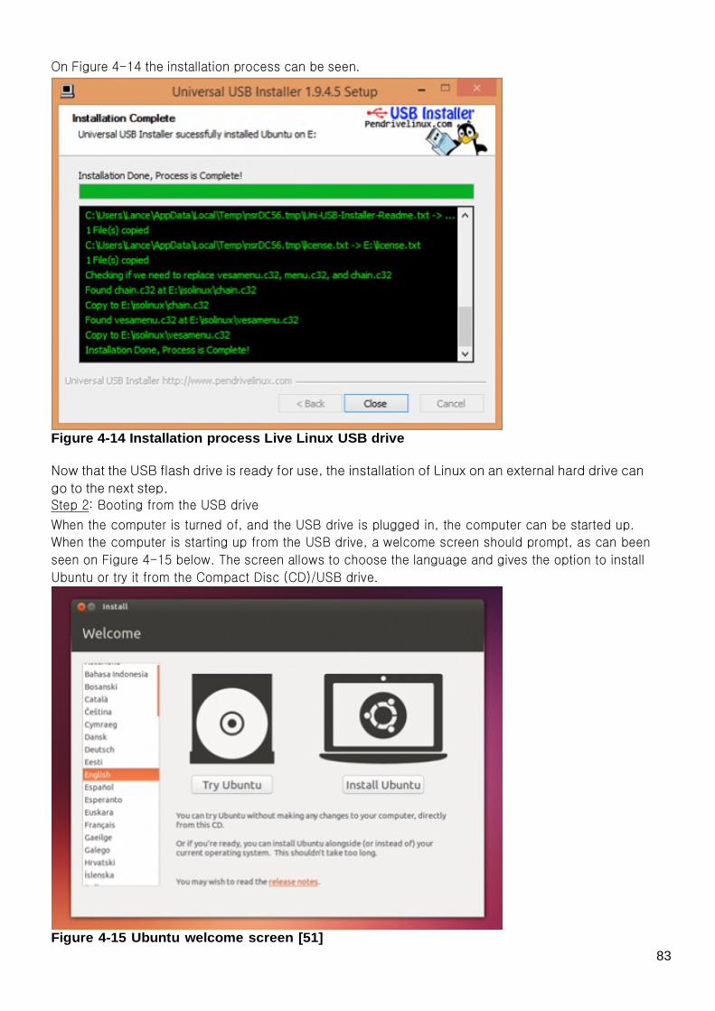
On Figure 4-14 the installation process can be seen.
Figure 4-14 Installation process Live Linux USB drive
Now that the USB flash drive is ready for use, the installation of Linux on an external hard drive can
go to the next step. Step 2: Booting from the USB drive
When the computer is turned of, and the USB drive is plugged in, the computer can be started up.
When the computer is starting up from the USB drive, a welcome screen should prompt, as can been
seen on Figure 4-15 below. The screen allows to choose the language and gives the option to install
Ubuntu or try it from the Compact Disc (CD)/USB drive.
Figure 4-15 Ubuntu welcome screen [51]
83

If the computer doesn't automatically do so, it might be needed to press the F12 key to bring up the
boot menu. Step 3: Preparing the installation of Ubuntu.
There should be enough space on the external hard drive to install Ubuntu on; however the
installation will check by default if the computer has enough free space at the beginning. When the
computer is connected to the internet, it's advised to select “Download updates while installing” and
“Install this third-party software now”. On Figure 4-16 these options are shown.
Figure 4-16 Prepare to install Ubuntu [51]
Step 4: Installation type
When there is already an OS present on the computer, a similar screen will be presented as on Figure
4-17 below.
Figure 4-17 Installation type [51]
84

In order to install Ubuntu on an external hard drive, the “Something else” option should be chosen.
This option will allow the creation of an own partition scheme and sizing (detail of which will be
described in the next step). Step 5: Making partitions on the external hard drive
When selected the “Something else” option, there will be presented a window similar to Figure 4-18.
Figure 4-18 Standard partition window Linux recognizes and assigns IDs to drives in a different manner to Windows. Linux recognizes drives
in the following way:
● Sda = 1st drive; ● Sdb = 2nd drive; ● Sdc = 3rd drive, and so on.
Partitions are also shown after the drive letters. For example, if there are two partitions on the first
disk, they would be identified as:
● Sda1 – 1st drive, 1st partition; ● Sda2 – 1st drive, 2nd partition.
The common Windows C label won't be shown in the disk menu of the above list. However, there are
key things for helping to recognize the Windows C drive. Both of these can be used to identify which
is the Windows disk.
● The size of the disk is shown; ● The name of the drive is shown.
So the window shows the current partition layout for the hard disks. If there are more than one disk,
they will show up as /dev/sda, /dev/sdb etc.
85

First, the Windows installation must be identified. On the previous picture the Windows installation is
located on sda1 (which is the first hard disk, first partition). To install the Linux on the external hard
drive, the external hard drive must be located on this menu. In order to divide the external hard drive into different partitions, the hard disk must must be selected,
then there must be clicked on the add button. This will show up the following window as can be seen
on Figure 4-19.
Figure 4-19 Create partition
Select almost the entire free space on the external hard drive- this will give a lot of space to work on
when working on the external hard drive. But there should be at least twice the Random-Access
Memory (RAM) space left to create a SWAP space.
Note: There can be selected up to a maximum of 4 primary partitions, or 3 primary partitions and 1
logical (which allows for another 64 partitions). The location for new partitions starts better at the
beginning of the free space. Ext4 is the recommended file system for Ubuntu, much the same as the
New Technology File System (NTFS) in Windows. The mount point is where the partition must mount.
A root partition is needed, which in Linux is denoted by a ”/”. After clicking ok, once finished setting the partition information, there will be a return to the partition
screen, showing the root partition that was just created. This method must be followed to create a
SWAP partition as well. It is recommend to set the size of the SWAP partition to, twice the size of the available RAM. For best
performance it is recommended to have the SWAP partition at the beginning or end of the drive. The device that has to be selected in the “Device for boat loader installation” drop-down menu is the
external hard drive. This can be seen on Figure 4-20 below. Note: When selecting the internal hard drive of the computer, the computer won't start up properly.
86

Figure 4-20 Device for boot loader installation
Once the changes are made, click “Install Now” to proceed to the next step.
Step 6: Selecting the location If the computer is connected to the internet, the location should be selected automatically (Figure 4-21). Check if the location is correct to proceed by clicking on ’Forward’.
Figure 4-21 Selecting the location [51]
87

Step 7: Selecting the preferred keyboard layout
When there are doubts about the keyboard layout, clicking the ’Detect Keyboard Layout’ button can
help (Figure 4-22).
Figure 4-22 Keyboard layout [51]
Step 8: Entering the login and password details
There will now be a “Who are you” screen, ready to be filled in with the user details as can be seen on
Figure 4-23. Note: The encrypt option doesn't have to be selected unless Ubuntu will be installed on an external
Hard Drive where there will be highly secure information on.
Figure 4-23 Login and password [51]
88

Step 9: Installing
In the next window there can be created a Ubuntu account or it can be chosen to create it later. Next
the installing will start; this can take some time (Figure 4-24).
Figure 4-24 Ubuntu Installing [51]
Step 10: Finishing
All that’s left is to restart the computer in order to start working on Ubuntu (Figure 4-25).
Figure 4-25 Ubuntu installation complete [51]
89

4.3 Installing Eclipse on Linux
4.3.1 Introduction
In this section will be explained how Eclipse must be installed on a Linux system (Ubuntu).
4.3.2 Installation guide The first step is downloading Eclipse Integrated Development Environment (IDE) for the Java Platform,
Enterprise Edition (Java EE) Developers. The download link can be found on:
http://www.eclipse.org/downloads/- (Figure 4-26). In order to program in the Java language the
“Eclispe IDE for Java EE Developers” must be selected.
Figure 4-26 Eclipse download link
Now an “Eclipse downloads – mirror selection” will be shown as can been seen on Figure 4-27.
Figure 4-27 Eclipse downloads - mirror selection
90

After selecting the mirror, the download can be started by selecting “Save file” (Figure 4-28). This will
save the folder “jdk-7u45-linux-i586.tar.gz” in the Downloads-folder, in the Home-directory.
Figure 4-28 Saving Eclipse
.tar folders stands for packed folders; so this folder must be unpacked before it can be used. This can
be done by selecting “extract here” after right mouse clicking on the .tar-folder. The folder “eclipse” will be created in the Downloads-folder as well.
Clicking on the eclipse.exe file will, however, give the following error (Figure 4-29):
Figure 4-29 Eclipse error
JDK stands for Java Development Kit: the JDK forms an extended subset of a software development kit
(SDK). It includes “tools for developing, debugging, and monitoring Java applications” [53]. JRE stands for Java Runtime Environment; this is a runtime-enviroment of Oracale which allows
executing Java-programs on a computer.
91

In order to start programming on Eclipse, JDK must be installed first. This will add the necessary libraries. The download link is:
http://www.oracle.com/technetwork/java/javase/downloads/jdk7-downloads-1880260.html.
The Licence Agreement must be accepted before it will allow any downloads. Then the right operating
system must be selected. When there is a 32bit-Linux system installed, the file named:
jdk-7u45-linux-i586.tar.gz must be selected. Like for the Eclipse download, this file will be packed and
saved in the Download folder in the Home directory. After unpacking, a folder named jdk1.7.0_45 is created in the Download folder as well (Figure 4-30).
Figure 4-30 The JDK folder in the Download folder
In order to solve the error from Figure 4-29 the folder called “jre” must be copied into the Eclipse
folder. The folder “eclipse” will now look like Figure 4-31 below.
92

Figure 4-31 Final Eclipse folder
Eclipse is now ready for programming.
Remark: When installing other versions of Eclipse the same error will appear; like for the Java version of Eclipse, simply copying the “jre” folder of the “jdk1.7.0_45” will solve it too.
When starting up Eclipse for the first time a folder called workspace must be created (Figure 4-32).
Eclipse will store the projects into this folder. The path where this folder may be created can be
changed by clicking on the “Browse…” button.
Figure 4-32 Choosing the location of the workspace folder
93

4.4 Compiling and running a Java program on Linux
4.4.1 Introduction
When trying to compile or run a Java program sometimes there can arise errors which can't be solved,
unless by compiling and running the program via the terminal. This was the case for the program that
simulates a serial connection on top of USB. 4.4.2 Manual
The following instructions will describe the steps needed to compile and run the program by using the
terminal. They will list the needed commands in order to compile and run the program. 1) Navigating to the file
Before the command to compile, or the command to run the file can be typed, the path must be
pointing to the location of the Java-file. The “cd” command is therefore needed: cd /home/usr/……/FileOfTheProgram
2) Compiling of the Java-file
Now the file can be compiled by using the “javac” command:
javac -cp /home/usr/LocationOfTheRXTXcommLibrary/RXTXcomm.jar: File.java An example can be seen on Figure 4-33 below:
Figure 4-33 A package for 'javac' is needed
94

As can be seen on Figure 4-33, in order to use the “javac” command one of the following packages
must be installed:
● default-jdk; ● ecj; ● gcj-4.6-jdk; ● gcj-4.7-jdk; ● openjdk-6-jdk.
3) Installing a package to use 'javac”
As explained in the previous point, one of the packages listed above must be installed.
As an example, the following command is given to install the first package: sudo apt-get install default-jdk
After installing this package, the compile command can be used again; now it should work without
any problems: javac -cp /home/usr/LocationOfTheRXTXcommLibrary/RXTXcomm.jar: File.java
4) Running the Java-file
After a successful compilation of the Java-file, the command to run the Java-program can be used: java -Djava.library.path=/home/usr/…/eclipse/jre/lib/i386_OrOtherOperatingSystem -cp
/home/usr/…/eclipse/jre/lib/ext/RXTXcomm.jar:.file
Remark: the file extension (.java) may not be given when using the last command
95

4.5 Making a backup from the home-folder on Linux
4.5.1 Introduction
There can be booting problems with the external hard-drive. When the external hard-drive gets
unplugged during a reading or writing cycle, or when there's a wrong starting up or shutting down
process, the booting file can get corrupted. This will result in a Kernel Panic error in the next boot-up.
In what follows, two solutions are given for this error. 4.5.2 Solutions
The first solution is to change the booting device back to the external hard-drive so it boots back from
the right booting file. The second solution is to reinstall the whole Ubuntu operating system again, by following the Project
Development Tools chapter – Installing Linux on an external hard-drive, but first of all a backup must
be made in order to not lose all the work. Following it will be explained how a backup can be made of
the entire home-folder on the external hard-drive. Step 1: Booting up from the live Ubuntu stick
As there was already made a Live Ubuntu stick by installing Linux for the first time on the external
hard-drive, this stick can be used again. When Ubuntu is started up choose for the “Try Ubuntu” option.
Step 2: Plug in the external hard-drive Step 3: Copying the home-folder to the chosen backup folder
There will be a problem trying to copy this folder because of the lack of permissions. The file is only
readable and executable by the user itself; when not being logged in the rights to do this are not
presented. So the permissions of the entire home-folder with the sub-folders and files must be
changed [54]. Step 4: Changing the permissions on the home-folder
In order to change permissions on files owned by a user, the sudo command will be needed (this will
require the password of that user). The command to change permissions is the chmod command;
using these together will give the solution.
Typing the following command in the terminal will allow all users to read, write and execute all the
files in the home-folder: sudo chmod -R 777 /media/ubuntu/149700c1-8158-4199-b62f-486b79ef8af6/home/
/media/ubuntu/149700c1-8158-4199-b62f-486b79ef8af6/home/ ⇒ this is the path to the home folder
on the external hard-drive; this will most likely be different since the name of the external hard-drive
will be different. The chmod command is used with numbers, the meaning meaning of these numbers can be seen in
Table 4-1. Usage: chmod {options} filename
Table 4-2 chmod options Options Definition #– owner
-#- group
96

–# other
1 execute
2 write
4 read Owner, Group and Other is represented by three numbers. To determine the number for each group,
the type of access needs to be determined first. Then the corresponding number should be added. Table 4-3 lists the different numbers with their corresponding access type.
Table 4-3 chmod numbers Owner Group Other read & write read & write read, write & execute
4+2=6 4+2=6 4+2+1=7 So the 777 means that the user, the group and all the others have the right to read, write and
execute. This will let the home-folder to be copied and used in the future.
97

5. Conclusions
5.1 Discussion
After 4 months of work, the project has fulfilled the expectations it was a real mix between research
and implementation. However, there has to be concluded that the research work took considerably more time than
expected at the beginning. This was because of the introduction of a second control unit that will take
care of the telemetry and configuration part. As a result, there were a lot of components which had to
be ordered, but to order the most suitable components, a research and comparison study had to be
done. This result was then discussed with the supervisors. The components which had to be ordered where the following: the control unit, the wireless
communication module and the external hard-disk. Further there was also a research about the
communication technique that was going to be used. The other task that took up a considerable amount of time was the integration of an operating system.
This operating system (Linux) had to be installed on an external hard drive provided with all the
necessary programs to fulfil the project. Because of the absence of any experience on Linux this was
harder then expected. Therefore different lists of instructions were written in the Project development
tools in order to prevent time lost in the future.
The third task, was to set up the communications. Therefore first a program that simulated a serial
connection on top of the USB had to be programmed on the Linux system. This was successfully
accomplished by writing it in the Java programming language. After this, the chosen wireless module
had to be implemented on the Linux system. In the end, the wireless module also made a successful connection with the internet.
There can be therefore concluded that the main tasks of this part of the project are completed; so, in
general view, the project can be seen as a success. Of course, it would not be possible to accomplish all of this individually. The support of all the
supervisors at LSA and the frequently held meetings led to this point. There also rested a joint work: the design and development of a self-defined protocol, which would
define the transfer of data and instructions between the two control units. This was a more complex
work then initially thought. Since the structure of the protocol had to be as complete as possible, this
took all the time that was left. However the protocol is totally defined, as complete as possible, and
the simulated serial connection on top of the USB is working. Therefore, it can be concluded that even if the main goals are achieved, there's still work left at this
project. This will be discussed in the next section.
98

5.2 Future Developments
5.2.1 Protocol
As mentioned in the previous section, the protocol is at this point totally defined but due to the
shortage of time it's not yet implemented. However the BeagleBone Black board and the STM32F3
Discovery board successfully communicate with each other using a serial connection which is
simulated on top of USB. 5.2.2 BeagleBone Black board
Since the BeagleBone Black board was to slow to work on directly, the same working environment
(Linux) was installed on an external hard drive as working place. Therefore, at this moment
everything is implemented on the external hard drive. At the end, when the protocol is also
implemented, the communication program that simulates the serial connection on top of USB should
be copied into the BeagleBone Black board. 5.2.3 Communication
As already mentioned in subsection “3.3.3.2 Important remarks” although the wireless module is
working, there are two important remarks regarding the use of this module:
● The default antenna of the module won't cover the 10 km range: Additional research must be done to find a suitable antenna to cover this range. There are already
some suitable antennas present at LSA, so maybe one of them could provide a suitable solution.
● The USB-hub provided by LSA needs an external power supply to provide the SR71-USB Wi-Fi
module with enough current: The provided USB-hub can be powered by an external power supply. So ordering the suitable external
power supply would fix the problem.
99

Bibliography
[1] European Project Semester, “A semester of international design for students in engineering,
science, and marketing”, 12 March 2013. [Online]. Available:
http://www.europeanprojectsemester.eu/info/Introduction [2] Geograph, “TR1028 : Marker Buoy, Dymchurch Beach”, 2007.[Online]. Available:
http://www.geograph.org.uk/photo/449545
[3] Data Buoy Cooperation Panel (DBCP), “Data Buoy Types”,.[Online]. Available:
http://www.jcommops.org/dbcp/platforms/types.html
[4] Wikipedia, “State of the art”, 4 November 2013. [Online]. Available:
http://en.wikipedia.org/wiki/State_of_the_art
[5] Davisnet, “DAVIS CABLED VANTAGE PRO2 WITH STANDARD RADIATION SHIELD”. [Online].
Available:
http://www.davisnet.gr/shop/pr_products_offers?htmlproikos=DAVIS&htmlprtype=&htmllang=2&html
prair=1&htmlproffer=0&htmlsearch=%&sessionid=-1396989624
[6] Novatel, “SUPERSTAR II”, 6 September 2005. [Online]. Available:
http://www.novatel.com/assets/Documents/Manuals/om-20000077.pdf
[7] Whatis, “Definition microcontroller”, March 2012. [Online]. Available:
http://whatis.techtarget.com/definition/microcontroller [8] Ziblog, “STM32F3-Discovery”, 12 September 2012. [Online]. Available:
http://ziblog.ru/2012/09/12/stm32f3-discovery.html
[9] Wikipedia, “Telemetry”, 2 January 2014. [Online]. Available: http://en.wikipedia.org/wiki/Telemetry
[10] Strainstall, “Oil and gas”. [Online]. Available:
http://www.strainstall.com/what-we-do/our-markets/oil-and-gas/
[11] Wikipedia, “Voyager 1”, 27 October 2013. [Online]. Available:
http://nl.wikipedia.org/wiki/Voyager_1
[12] Indincredible.blogspot, “F1 race is going to hit our country-India will host F1 Grand pics 2011”, 4
September 2011. [Online]. Available: http://indincredible.blogspot.pt/2011/09/f1-race-is-going-to-hit-our-country_04.html
[13] ProWeatherStation , “Complete weather information in a compact low cost system”. [Online].
Available: http://proweatherstation.com/
[14] Space 4 Peace, “Report from the GN’s 2013 Space Conference: The High North and International
Security”, 27-29 June 2013. [Online]. Available:
http://www.space4peace.org/reports/gn_conference_13.htm [15] Latrobe Regional Hospital, “Critical Care Unit”. [Online]. Available:
http://www.lrh.com.au/home/orginfo/departments/criticalcare/Critical%20Care%20Unit.html/?hideleftn
av=1&hideheader=1&noHeader=1&nofooter=1&nofooterProcess=1&printit=1
[16] Acoustic Ecology Institute, “Ears Wide Open”, November 2008. [Online]. Available:
http://www.acousticecology.org/members/bulletinarchives/bulletin12bytes.html
[17] Daily News, “Leandra's new law: Convicted drunk drivers who don't install BAC car device may
wear ankle monitor”, 16 October 2011. [Online]. Available:
http://www.nydailynews.com/new-york/leandra-new-law-convicted-drunk-drivers-don-install-bac-car-d
evice-wear-ankle-monitor-article-1.965541 [18] BeagleBone Black, “BeagleBone Black”, 4 December 2013. [Online]. Available:
http://beagleboard.org/Products/BeagleBone%20Black
[19] Embedded Linux Wiki, “Beagleboard:BeagleBoneBlack”, 15 January 2014. [Online]. Available:
http://circuitco.com/support/index.php?title=BeagleBoneBlack
[20] Mouser, “BeagleBone Black System Reference Manual”, 12 May 2013. [Online]. Available:
http://www.mouser.com/catalog/specsheets/BBB_SRM.pdf
[21] Farnell, “RaspberryPi”. [Online]. Available: http://downloads.element14.com/raspberryPi1.html
100

[22] Tecnologías de la Información, Energía y Comunicaciones (TIECs), “Instalar Raspberry pi desde
Windows”. [Online]. Available: http://www.cmdearcos.es/tiecs.php/instalar-raspberry-pi-desde-windows
[23] Farnell, “ERA-CONNECT2-PI”. [Online]. Available:
http://be.farnell.com/lprs/era-connect2-pi/module-rf-dongle-connect-2-pi/dp/2147161
[24] STMicroelectronics, “STM32F3DISCOVERY”. [Online]. Available:
http://www.st.com/web/en/catalog/tools/FM116/SC959/SS1532/PF254044
[25] Oceandata, “DATA BUOY CMB 4280”, April 2006. [Online]. Available:
http://www.oceandata.co.kr/GroupWare/Home/product/brochure/aanderaa/DB4280.pdf
[26] Nexsens, “Data Buoys Sized for Any Application”. [Online]. Available:
http://www.nexsens.com/products/nexsens_data_buoys
[27] Faculdade de Engenharia da Universidade do Porto (FEUP), “FEUP Autonomous Sailboat (FASt)”, 1
Jan 2009. [Online]. Available: http://paginas.fe.up.pt/~jca/fast/en/index.php [28] Wikipedia, “Bluetooth”, (15 January 2014). [Online]. Available:
http://en.wikipedia.org/wiki/Bluetooth
[29] Buzzle, “Advantages and Disadvantages of Bluetooth Technology”, 9 June 2011. [Online].
Available:
http://www.buzzle.com/articles/advantages-and-disadvantages-of-bluetooth-technology.html
[30] Wikipedia, “Wi-Fi”, 12 January 2014. [Online]. Available: http://en.wikipedia.org/wiki/Wi-Fi
[31] Kioskea.net, “WiFi - Description and explanations”, January 2014. [Online]. Available:
http://en.kioskea.net/faq/9081-wifi-description-and-explanations [32] About.com, “What is GSM? Definition of GSM: Cell Phone Glossary”. [Online]. Available:
http://cellphones.about.com/od/phoneglossary/g/gsm.htm
[33] Tutorialspoint (TP), “GSM - Specification”. [Online]. Available:
http://www.tutorialspoint.com/gsm/gsm_specification.htm
[34] Linux Hardware Guide.com, “TP-Link TL-WDN3200 N600 Dual-band WiFi Adapter (2,4GHz,
300Mbps, USB 2.0)”, 17 August 2013. [Online]. Available:
http://www.linux-hardware-guide.com/ca/2013-05-30-tp-link-tl-wdn3200-n600-dual-band-wifi-adapter-
24ghz-300mbps-usb-2-0 [35] TurboWiFi, “TURBOWIFI V1 OUTDOOR HIGH POWER USB WIFI ANTENNE PER STUK”. [Online].
Available: http://www.wifiantennes.nl/index.php?action=article&aid=705&lang=NL
[36] Digital Yacht, “WL450 Long Range Smart Wi-Fi Antenna”. [Online]. Available:
http://www.digitalyacht.co.uk/product_info.php?products_id=11708 [37] Alfa Network, “Tube-U(N)”. [Online]. Available:
http://www.alfa.com.tw/products_show.php?pc=28&ps=12
[38] Pcnautic, “Wifi Marine USB 1000mW 9dBi”. [Online]. Available:
http://www.pcnautic.nl/Wifi-/-WLAN/Nieuw-Wifi-Marine-USB-1000mW-9dBi/vmj_color_plus.tpl.html
[39] SimpleWiFi, “Alfa AWUSO36H 1000mW USB Adapter PLUS 9dBi Antenna”. [Online]. Available:
http://www.simplewifi.com/alfa9.html
[40] Ubiquiti Networks, “SR71-USB World's First Hi-Power 11n USB Radio”. [Online]. Available:
http://dl.ubnt.com/sr71usb_datasheet.pdf
[41] Ubiquiti Networks, “Mobility”. [Online]. Available:
http://www.ubnt.com/support/downloads/mobility
[42] Wifi KING, “Ubiquiti SR71USB, 802.11a/b/g/n, USB, 24dBm, 250mWatt, MIMO”. [Online]. Available:
http://www.wifiking.com/en/ubiquiti-networks/boards-and-cards/2-4-ghz/ubiquiti-sr71usb-802-11a-b-g-
n-usb-24dbm-250mwatt-mimo/a-7110/
[43] Hipstercircuits, “Finally a working 4.3″ HDMI compatible LCD for BeagleBone Black!”, 7 July 2013.
[Online]. Available: http://hipstercircuits.com/finally-a-working-4-3-hdmi-compatible-lcd/
[44] Digital inspiration, tech à la carte, “How to Install Linux on your Windows Computer”, 25 June
2012. [Online]. Available: http://www.labnol.org/software/run-linux-with-windows/19746/
101

[45] jfnlinuxproject.blogspot, “How to install Ubuntu 11.04 under Windows 7 64 bit”, 5 September
2011. [Online]. Available:
http://jfnlinuxproject.blogspot.pt/2011/09/how-to-install-ubuntu-1104-under.html
[46] What's A Byte? Megabytes, Gigabytes, Terabytes, “Creating a Bootable USB Drive with True
Image 2014”. [Online]. Available: http://www.whatsabyte.com/P1/ATI_2010_USB_Boot.html [47] Western Digital, “Portable Hard Drives, WD Elements”. [Online]. Available:
http://www.wdc.com/en/products/products.aspx?id=470
[48] Wikipedia, “USB hub”, 8 December 2013. [Online]. Available:
http://en.wikipedia.org/wiki/USB_hub
[49] Pna, Alarm & Advies, “Multimedia”. [Online]. Available:
http://www.alarmadvies.eu/catalog/index.php?cPath=3
[50] Beagleboard, “Getting Started with BeagleBone & BeagleBone Black”, 13 Dec 2013. [Online].
Available: http://beagleboard.org/Getting%20Started
[51] Ubuntu, “Install Ubuntu 13.10”. [Online]. Available:
http://www.ubuntu.com/download/desktop/install-desktop-latest
[52] Adafruit learning system, “Flashing the BeagleBone Black”, 6 January 2013. [Online]. Available:
http://learn.adafruit.com/beaglebone-black-installing-operating-systems/flashing-the-beaglebone-blac k [53] Wikipedia, “Java Development Kit”, 14 January 2014. [Online]. Available:
http://en.wikipedia.org/wiki/Java_Development_Kit
[54] Stackoverflow, “How to set chmod for a folder and all of its subfolders and files in Linux Ubuntu
Terminal?”, 12 January 2014. [Online]. Available:
http://stackoverflow.com/questions/3740152/how-to-set-chmod-for-a-folder-and-all-of-its-subfolders-a nd-
files-in-linux-ubunt
102

Appendices Protocol examples:
sirf_protocol.pdf
sirf_software_interface_1.0.pdf An overview of the upcoming Wi-Fi standards: IEEE 802.11ac and 802.11ad
gbit_wlan-r6.pdf Datasheet of the SR71-USB Wi-Fi module:
sr71usb_datasheet.pdf
From:
http://ave.dee.isep.ipp.pt/~1131043/ - Autonomous Environmental Buoy/Regatta Beacon
Permanent link:
http://ave.dee.isep.ipp.pt/~1131043/doku.php?id=report
Last update: 2014/01/15 22:37
103