autonomous greenhouse gas sampling using multiple robotic boats
TRANSCRIPT

Autonomous Greenhouse Gas SamplingUsing Multiple Robotic Boats
Matthew Dunbabin
Abstract Accurately quantifying total greenhouse gas emissions (e.g. methane)from natural systems such as lakes, reservoirs and wetlands requires the spatial-temporal measurement of both diffusive and ebullitive (bubbling) emissions. Tradi-tional, manual, measurement techniques provide only limited localised assessmentof methane flux, often introducing significant errors when extrapolated to the whole-of-system. In this paper, we directly address these current sampling limitations andpresent a novelmultiple robotic boat systemconfigured tomeasure the spatiotemporalrelease ofmethane to atmosphere across inlandwaterways. The system, consisting ofmultiple networked Autonomous Surface Vehicles (ASVs) and capable of persistentoperation, enables scientists to remotely evaluate the performance of sampling andmodelling algorithms for real-world process quantification over extended periods oftime. This paper provides an overview of the multi-robot sampling system includingthe vehicle and gas sampling unit design. Experimental results are shown demon-strating the system’s ability to autonomously navigate and implement an exploratorysampling algorithm to measure methane emissions on two inland reservoirs.
1 Introduction
Quantification of greenhouse gas emissions to atmosphere is becoming an increas-ingly important requirement for scientists and managers to understand their total car-bon footprint. Methane in particular is a powerful greenhouse gas, approximately 21times higher globalwarming potential than carbon dioxide.Water storages are knownemitters of methane to atmosphere [11]. The spatiotemporal variation of release isdependent on many environmental and biogeochemical parameters. Therefore, inorder to accurately quantify this greenhouse gas release requires long duration andrepeat monitoring of the entire water body.
M. Dunbabin (B)Institute for Future Environments, Queensland University of Technology,2 George Street, Brisbane, QLD 4000, Australiae-mail: [email protected]
© Springer International Publishing Switzerland 2016D.S. Wettergreen and T.D. Barfoot (eds.), Field and Service Robotics,Springer Tracts in Advanced Robotics 113, DOI 10.1007/978-3-319-27702-8_2
17

18 M. Dunbabin
There are two primary pathways for methane to be released from water storages;(1) diffusion, and (2) ebullition (or bubbling). Diffusion is themost common pathwayconsidered due to greater consistency across a waterway. Rates of methane ebullitionrepresent a notoriously difficult emission pathway to quantify with highly variablespatial and temporal changes [6]. However, the importance of bubbling fluxes interms of total emissions is increasingly recognised from a number of different glob-ally relevant natural systems including lakes, reservoirs andwetlands. This representsa critical challenge to currentmanual survey efforts to quantify spatiotemporal green-house gas emissions and reduce the uncertainty associated with bubbling fluxes. Thisis where robotics can play a significant role.
In this work, a novel system for direct measurement of the combined diffusiveand ebullitive methane flux and an ability to persistently monitor a wide spatial areais presented. Named the Inference Robotic Adaptive Sampling System, it consistsof multiple (four) networked robotic boats (see Fig. 1) and provides an open archi-tecture allowing researchers to evaluate new sampling algorithms with customisablescientific payloads on real-world processes over extended periods of time.
The contributions presented in this paper are; (1) A novel ASV system for nav-igating complex inland waterways, (2) a new greenhouse gas sampling system, (3)a multi-robot sampling strategy to survey a previously unseen environment, and (4)an experimental evaluation of the entire system on two inland water storages.
The remainder of this paper is as follows: Sect. 2 provides background informa-tion. Section3 describes the Inference system and the gas sampling system. Section4describes a preliminary sampling methodology with Sect. 5 showing results fromtwo inland water storages. Finally, Sect. 6 draws conclusions and discusses futureresearch.
Fig. 1 The multi-robot Inference Robotic Adaptive Sampling System

Autonomous Greenhouse Gas Sampling Using Multiple Robotic Boats 19
2 Related Work
Robotic platforms capable of persistent environmental monitoring offer an efficientalternative to manual or static sensor network sampling for studying large-scalephenomena. However, in practice most applications are short-term experiments forvalidating existing models [3]. Recent cross-disciplinary research extensively usedrobots to investigate assumptions around spatiotemporal homogeneity of environ-mental processes such as toxic algal blooms in lakes [5] and methane production inreservoirs [6]. These studies show that combined robotic persistence and spatiotem-poral sampling can provide significant new insight into environmental processes.However, there are challenges to achieving persistent robotic process monitoring,particularly in the complex environments considered here. These primarily relate torobotic platforms for persistent navigation within complex and often dynamic envi-ronments, and the ability to adaptively coordinate multiple robots to appropriatelysample the process of interest.
Robotic monitoring of marine and aquatic environments has received consider-able attention over the last two decades [3]. Whilst most studies have focused onunderwater vehicles with restricted payloads and endurance, there is now increasingfocus on Autonomous Surface Vehicles (ASVs) with greater endurance and payloadcarrying capacity for large-scale unsupervised environmental monitoring [12, 13,16]. These systems are primarily designed for oceanographic surveys and are notparticularly suitable for relatively unexplored inland waterways with challengingand often varying navigational requirements.
Recently, a series of ASVs have been designed and applied on inland waterways.Typically, these catamaran style vehicles are of sufficient size for carrying scientificpayloads for tasks such as mapping hazards above and below the waterline [4], andwater quality monitoring [1, 7]. Whilst demonstrating environmental monitoringcapabilities, there is little flexibility for adding external payloads and their navigationcapabilities are generally customised to the specific environment. The provision ofa flexible, yet capable, robotic platform is a key consideration in this research.
Navigation around narrow inlandwaterways is oftenmore challenging than for theocean due to issues such as above, below and on-water obstacles and GPS reliability(e.g. in mountainous and forested systems). A number of sensors have been used todetect obstacles and in identifying free-space paths.Hitz et al. [7] usewater depth onlyfor detecting shallow regions, whereas Ferreira et al. [4] and Leedekerden et al. [9]use scanning laser range finders and sonar to produce high-resolution 3Dmaps of theabove and below water environment. Cameras have also been proposed for detectingspecific objects on the water [2, 4]. Scherer et al. [14] have used cameras and laserscanners (albeit on an aerial robot) to map the edges of waterways and the free-spaceabove the water as the robot traverses them. Whilst high-resolution sensors such aslasers and sonar can provide robust navigation capabilities, for persistent monitoringtheir power consumption can be a particular challenge. Exploiting lower power, andcost, sensing modalities such as vision and ultrasonics to provide sufficient obstacledetection capabilities is a goal of this research.

20 M. Dunbabin
The overall coordination of the mobile sensors (robots) is critical to accuratelymeasure spatiotemporal environmental processes. An emerging research area forASVs is that of mobile adaptive sampling where the ASV can alter its trajectory toimprove measurement resolution in space and time (e.g. [17]). The survey paper [3]summarises advances in robotic adaptive sampling for environmental monitoring.Past research has focused primarily on the Gaussian Process-based reconstructionof stationary processes using combinations of mobile and static sensors networks[8, 17]. Whilst demonstrating the ability to capture and reconstruct various para-meter distributions, these studies offer simulation only or short duration small-scaleexperimental validation. Larger-scale adaptive coordination of mobile sensing assets(underwater gliders) has been considered for tracking large oceanographic plumesin [10, 15]. Developing and demonstrating multi-robot adaptive sampling algo-rithms for the large-scale monitoring and tracking of spatiotemporal environmentalprocesses is an over-arching goal of this research.
3 The Inference Autonomous Surface Vehicle
This section describes the current Inference Robotic Adaptive Sampling system andthe greenhouse gas sampling payload system as applied and evaluated in this paper.
3.1 High-Level Scenario
The Inference Robotic Adaptive Sampling system was developed with the goal ofproviding a shared resource of multiple networked ASVs to allow researchers toremotely evaluate new sampling algorithms on real-world processes over extendedperiods of time. A typical use scenario proposed for the system is outlined below:
1. The ASVs, each carrying a scientific payload, are deployed on a water body.2. Based on a desired sampling protocol (e.g. random, adaptive) and process mod-
elling requirements, new sampling locations are determined. This can be achievedeither from a remote centralised, or an on-board decentralised process.
3. Determine which ASV goes to each of the updated sample locations. This mayinvolve optimising a cost function (e.g. minimising energy and/or travel time,maximising solar energy harvesting).
4. Each ASV navigates to their commanded sampling location.5. Each ASV takes its scientific measurement and reports it back through the net-
work.6. Repeat steps 2–5 until a termination condition is met.
The system described in this paper is working towards achieving this goal witha preliminary experimental evaluation of this scenario using a simplified randomexploration algorithm as described in Sect. 4.

Autonomous Greenhouse Gas Sampling Using Multiple Robotic Boats 21
Fig. 2 One of the autonomous surface vehicles from the Inference system. The navigation sensors,computing and batteries are located underneath the two solar panels. The scientific payload isattached to the moon-pool opening underneath the camera. Note the pan-tilt dome camera visiblewas not used in this study, only the smaller USB camera directly in front of it
3.2 Hardware Overview
The Autonomous Surface Vehicles used in the multi-robot Inference system are cus-tom designed for persistent and cooperative operation in challenging inland water-ways. The overall hull shape (see Fig. 2) has four key features; (1) A low draftallowing traversal in shallow water, (2) open sides and low curved top deck to min-imise windage and the associated drift when station keeping during sampling, (3) alarge top surface area angled for maximising energy harvesting from the solar panels,and (4) a moon-pool (open centre section) with standardised attachment points tomount custom sensor packages. The overall dimensional and mass specifications forthe ASVs are given in Table1.
Table 1 Physical andperformance specifications ofthe ASVs
General specifications
Length 1.50 m
Width 1.50 m
Height (above waterline) 0.7 m
Draft 0.15 m
Weight 33 kg (without payload)
External payload: 4 kg
Propulsion 2 × BlueRobotics T100brushless electric thrusters
Power 12V 20Ah LFP battery
2× 40 W solar panels
Speed Max: 2.3 ms−1
Typical survey: 0.5–0.8 ms−1

22 M. Dunbabin
Propulsion of theASVs is provided by twoBlueRobotics T100 brushless thrustersmounted at the rear of each side of the hull. These provide the forward motion aswell as steering (through differential control) of the vehicles. The system is poweredby a single 20 Ah Lithium Iron Phosphate battery and two 40W solar panels. Thislimited energy capacity requires advanced path-planning algorithms to coordinatethe ASVs for maximising energy harvesting as well as to meet the overall samplingobjectives. These algorithms are current ongoing research and not considered in thispaper.
The ASVs are required to autonomously navigate inland waterways using onlytheir on-board sensors. Each ASV has a suite of low-cost navigation sensors whichinclude a GPS, magnetic compass with roll and pitch, and a depth sensor for mea-suring bathymetry. Of particular importance is the ability to detect the water’s edgeand potential obstacles on top of the water. The obstacle sensors used in this studyare a USB camera (Microsoft LifeCam) mounted above the moon-pool, and fourMaxbotix ultrasonic range sensors mounted just under the leading and trailing edgesof the top deck. These sensors are used to detect the edge of the water and at-surfacestructure such as reeds, trees and water lilies (see Sect. 4). To minimise power con-sumption and cost, typical scanning laser-based or radar sensors are not currentlyused, although they can be added if required in future scenarios.
The ASV’s thrusters are controlled via a custom designed motor and sensor inter-face board. This system is capable of providing waypoint control and ultrasonic anddepth sensor based obstacle avoidance. To facilitate vision-based obstacle avoidance,each ASV has an Odroid C1 ARM Cortex-A5 1.5 GHz quad core CPU running theRobotic Operating System (ROS) and OpenCV.
There are two communication systems on-board the ASVs. The first is a 2.4 GHzWiFi system allowing communication to a gateway located on a floating platformon the water storage. This gateway has a wireless router and 3G modem allowingbidirectional data transfer from a centralised server located at the Queensland Uni-versity of Technology. The second is a 2.4GHz wireless embedded system (XBeeIEEE 802.15.4) allowing serial communication between each vehicle as well as withexisting static floating sensor nodes located on the water body.
Each ASV is capable of carrying additional custom payloads weighing up to4kg. The payload is mounted under the moon-pool opening via six attachment bolts.Currently available payloads include gas sampling (see Sect. 3.3), multi-beam andprofiling sonars, water sampling and a winch system for water column profiling. Asix pin connector is provided for use by the custompayloads. This connector providespower as well as bi-directional serial communications via a standardised protocolfor triggering sampling, and reporting sample completion and possible faults.
3.3 Gas Sampling System
The goal of this study is tomeasure greenhouse gas emissions (efflux) from thewater-way. Figure3 shows the self-contained greenhouse Gas Sampling System (GSS)

Autonomous Greenhouse Gas Sampling Using Multiple Robotic Boats 23
developed to autonomously measure both the diffusive and ebullitive efflux. Thispayload is mounted underneath the ASV via the moon-pool payload attachmentpoints as described in Sect. 3.2.
The GSS (Fig. 3) automates the traditional manual chamber-based samplingprocess and consists of three primary components; (1) A frame allowing the lower-ing and raising of a chamber into the water, (2) a chamber fitted with a continuousmethane gas (CH4) sensor and purge valve, and (3) a physical gas sampling unit.
The process of sampling the greenhouse gas being released from the water to theatmosphere using theGSS is illustrated in Fig. 4 and consists of four steps. Firstly, theASV navigates to the desired sampling location it goes into a weak station-keepingmode. This limits the control input to the motors to reduce any disturbance that mayinfluence the CH4 efflux at the expense of a slightly increased station bound. At this
Fig. 3 The Gas Sampling System (GSS) used to measure greenhouse gas (methane) release toatmosphere from the inland water storages. The GSS is attached to the ASV as described in Sect. 3.2
Fig. 4 The sequence of actions required to measure greenhouse gas using the GSS

24 M. Dunbabin
point, the chamber purge valve (see Fig. 3) is opened and the chamber lowered usingthe linear actuator to achieve a desired air volume within the chamber (Fig. 4a–c).The second step involves closing the chamber purge valve and letting the methaneconcentration within the chamber increase for a predetermined incubation time (seeSect. 4 for a discussion on incubation time). During incubation, the methane sensorcontinuously measures the concentration within the chamber (Fig. 4b, c). At the endof the incubation, the third step (Fig. 4c) calculates the overall gas efflux rate fromthe gradient of the recorded methane concentration time history. Also a physicalsample of gas from the chamber is collected for laboratory analysis using the gassampling unit (see Fig. 3). This involves a sequence of actions that firstly purges thesample tube using the pump, then loads a pre-evacuated 12mL vial into the samplingunit. A linear actuator on the unit drives a hypodermic needle into the vial whilstpumping gas from the chamber. Once 20mL of gas has been pumped into the vial(over pressure sampling technique), the needle retracts and the unit discharges thevial ready for the next sample.
After sampling is completed, the final step involves opening the chamber purgevalve and raising the chamber out of the water. At this point the ASV can move tothe next sample location.
4 Technical Approach
This section outlines technical details relating to the sampling of greenhouse gas(methane), obstacle avoidance, and the sample site selection algorithms used forcoordinating a number of the ASVs across a previously unexplored water body.
Gas Sampling Protocol
During the sampling phase, the concentration measured by the methane sensor ispolled every 2 s for the entire incubation period. A linear least squares line of bestfit applied to this time history and the gradient used to calculate the flux rate.
A key consideration for greenhouse gas sampling is determining the minimumincubation time that maximises detection accuracy. The output from the continuousmethane sensor in theGSS is quantised to 0.01%.While diffusive fluxes are typicallyless than 50 mg m−2 d−1, ebullitive fluxes in our region can be has high as 22,000mg m−2 d−1 [6]. Varying the incubation time and/or head-space ratio (i.e. the ratioof chamber surface area (Ac) to its internal air volume (Vc)) can be used to achievea desired detection accuracy. Figure5 shows the predicted variability in relativemeasurement error (i.e. the percentage error between a true methane flux to thatwhich can be measured by the GSS) versus incubation time for different methaneefflux rates and head-space ratios. As can be seen, longer incubation times leadto reduced errors as with increasing head-space ratios. However, longer incubationtimes mean less sample points can be performed per day. In this study, the primary

Autonomous Greenhouse Gas Sampling Using Multiple Robotic Boats 25
Fig. 5 The predictedpercentage relativemeasurement error ofmethane flux rate withincubation time for theprototype GSS (see Sect. 3.3)with a sensor outputresolution of 0.01%. Twoefflux rates are considered,1000 and 5000 mg m−2 d−1
with head-space ratios(Ac/Vc) of 10 and 20 m−1
interest is the detection of methane “hot-spots”, that is where it is bubbling from thewater. Therefore, incubation times of 15–20min were chosen here to allow detectionof methane rates as low as 1000 mg m−2 d−1, albeit at lower accuracy. However, thehigher the efflux rate, the more accurate the measurement.
Obstacle Avoidance
The ASVs have three sensors for obstacle avoidance; (1) ultrasonic sensors, (2) acamera, and (3) water depth sensor. The ultrasonic sensors have a maximum rangeof 6.5m and are used to detect above water objects in front of the ASV such as land,reeds, trees and larger buoys. The camera, only used when moving between samplewaypoints, is used to detect water lilies on the water’s surface. The image stream isprocessed at 1Hz.With the camera fixed to theASV, the horizon can be approximatedand only the scene below the horizon considered. Image segmentation is conductedusing an empirically determined threshold on the green and blue color channels withan approximate water lily size threshold to reduce noise. Figure6 shows an exampleimage from an ASV and the resulting segmentation of the water lilies (shown in red).
To detect shallow, non-traversable water, the depth of water below the ASV iscontinuously monitored. The outputs from all obstacle sensors are parsed by theon-board controller. When a detection occurs, the ASV trajectory is modified asdescribed in the following section.
Multi-robot Sample Site Selection
A random walk-based algorithm is proposed here for selecting locations for n ASVsto sample the environment in an attempt to identify regions with high methane gasflux. There are two key assumptions: (1) the boundary of the water body is knownfrom sources such as GIS, and (2) the ASVs can communicate between each other

26 M. Dunbabin
Fig. 6 Example of image segmentation from the ASV for detecting on-water obstacles such aswater lilies (Left original image. Right image with detected obstacles highlighted in red)
and can share their list of previous and next sample locations. In this study, we donot use bathymetry but it could be used in the future to help guide the algorithm.
The selection of new sample locations is based on an online random walk andpotential fields. Iterating through each robot, the basis of the algorithm is as follows:
1. All previously sampled sites for all robots are represented as 2D Gaussian poten-tials centred at those points with fixed amplitude and standard deviation.
2. A random position at radius r from the current position is selected. If this positionis not on land, and the value from the closest Gaussian potential is less than athreshold, this becomes the next sample point for that robot. If this condition isnot met, the process is iterated until a location can be found. If no location can befound after a set number of iterations, the search radius is increased by �r andthe process repeated until a site is found or some termination criteria is met.
3. To increase local intensification of sampling in methane “hot-spots”, if the mea-sured flux rate at the robot’s current location exceeded some threshold, the searchradius for the next sample step is set to βr where (0 < β ≤ 1) and the potentialthreshold trigger relaxed.
During waypoint execution each robot drives in a straight line towards the goal. Ifthe water depth falls below a threshold (i.e., too shallow), or an obstacle is detected,the vehicle starts to move either clockwise or counter clockwise around the contouruntil a new straight line to the goal can be achieved. This entire process is repeated forall robots until a desired number of samples are collected or some other terminationcondition met.
5 Results
An experimental evaluation using two ASVs with gas sampling payloads was con-ducted on two water reservoirs in South East Queensland, Australia; (1) Gold CreekDam, and (2) Little Nerang Dam. These are established study sites and selected as

Autonomous Greenhouse Gas Sampling Using Multiple Robotic Boats 27
they exhibit regions of significant methane ebullition and provide a range of chal-lenging operational conditions for evaluating robotic systems.
Previous studies [6] had collected georeferenced outlines of the water’s edge(boundary) as well as bathymetry maps for both sites. Only the boundary was usedin this study for implementing the sample site selection algorithmdescribed in Sect. 4.Figure7 shows the two ASVs used in this study on Gold Creek Dam.
The first experiment was conducted at Gold Creek Dam. This is a small, relativelyopen dam with a narrowing distal arm. The sample selection algorithm was run tocollect 12 samples for each ASV, with a step radius of 100 m, and intensificationfactor of 0.5. The trigger was set at 1000 mg m−2 d−1 with 20min incubations. Thetime to complete the sampling was approximately 5 h. Figure8 shows the results ofimplementing the sample strategy for both ASVs. These results show the ASVs werecapable of navigating the water storage and implementing the sample protocol. Theonline detections of methane exceeding the trigger threshold (markers in yellow)correspond to areas physically observed to have methane ebullition. As ebullitionis essentially a point source emitter, there can be extreme variability even at shortspatial and temporal scales (see [6]). Therefore, whilst ebullition can often be seenin expected regions (e.g. top image of Fig. 8) a sample within that region does notalways guarantee the capture of gas bubbles sufficient to achieve high rates.
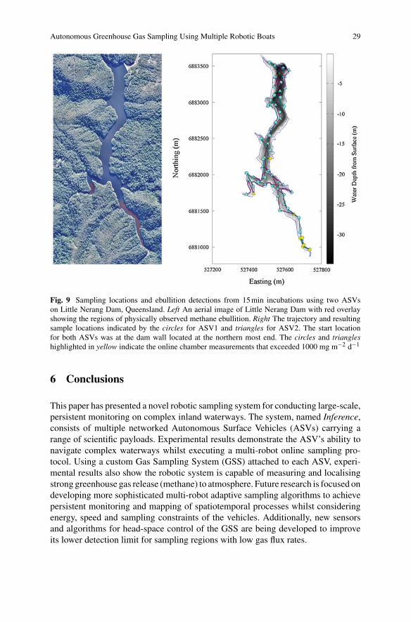
A second experiment was conducted at Little Nerang Dam. This is a longer andnarrower water storage with a steep sided catchment. The sample selection was runwith a total of 30 samples for each ASV, step radius of 200m and an intensificationfactor of 0.5. The trigger was set at 1000 mg m−2 d−1 with 15min incubations. Thetime to complete the experiment was approximately 10.5 h.
Figure9 shows the results of implementing the sample strategy for both ASVs.These results again show the ASVs ability to implement the sample protocol and
Fig. 7 The two ASVs at the start of a sampling campaign on Gold Creek Dam, Queensland. Theretracted gas sampling unit is visible underneath the ASV on the right

28 M. Dunbabin
Fig. 8 Sampling locations and ebullition detections from 20min incubations using two ASVs onGold Creek Dam, Queensland. Top An aerial image of Gold Creek Dam with red overlay showingthe regions of physically observed methane ebullition. Lower The trajectory and resulting samplelocations indicated by the circles for ASV1 and triangles for ASV2. The start location for bothASVs is indicated by the green dot. The circles and triangles highlighted in yellow indicate theonline chamber measurements that exceeded 1000 mg m−2 d−1
navigate the water storage. The online detections of methane exceeding the triggerthreshold (markers in yellow) are consistent with previous research at the dam [6].
Whilst these experiments demonstrated the system for real-time sampling ofgreenhouse gases across water bodies, the online component of gas sampling systemwas not optimised for detecting lower (and more common) flux rates of less than1000 mg m−2 d−1. Future work will look at adaptive chamber head-space controlas well as higher precision sensors to improve the utility of the system for accuratequantification of the combined diffusive and ebullitive flux of greenhouse gases.
Autonomous Greenhouse Gas Sampling Using Multiple Robotic Boats 29
Fig. 9 Sampling locations and ebullition detections from 15min incubations using two ASVson Little Nerang Dam, Queensland. Left An aerial image of Little Nerang Dam with red overlayshowing the regions of physically observed methane ebullition. Right The trajectory and resultingsample locations indicated by the circles for ASV1 and triangles for ASV2. The start locationfor both ASVs was at the dam wall located at the northern most end. The circles and triangleshighlighted in yellow indicate the online chamber measurements that exceeded 1000 mg m−2 d−1
6 Conclusions
This paper has presented a novel robotic sampling system for conducting large-scale,persistent monitoring on complex inland waterways. The system, named Inference,consists of multiple networked Autonomous Surface Vehicles (ASVs) carrying arange of scientific payloads. Experimental results demonstrate the ASV’s ability tonavigate complex waterways whilst executing a multi-robot online sampling pro-tocol. Using a custom Gas Sampling System (GSS) attached to each ASV, experi-mental results also show the robotic system is capable of measuring and localisingstrong greenhouse gas release (methane) to atmosphere. Future research is focused ondeveloping more sophisticated multi-robot adaptive sampling algorithms to achievepersistent monitoring and mapping of spatiotemporal processes whilst consideringenergy, speed and sampling constraints of the vehicles. Additionally, new sensorsand algorithms for head-space control of the GSS are being developed to improveits lower detection limit for sampling regions with low gas flux rates.

30 M. Dunbabin
Acknowledgments The author would like to thank Alistair Grinham and Katrin Strum from theUniversity of Queensland for their assistance with the initial gas sampling unit and ASV prototypeevaluation, and laboratory processing of gas samples. Also thanks to Riki Lamont for his assistancein the payload integration and commissioning of the ASVs.
References
1. Dunbabin, M., Grinham, A.: Experimental evaluation of an autonomous surface vehicle forwater quality and greenhouse gas monitoring. In: Proceedings of International Conference onRobotics and Automation, pp. 5268–5274, May 2010
2. Dunbabin, M., Grinham, A., Udy, J.: An autonomous surface vehicle for water quality moni-toring. In: Proceedings of Australasian Conference on Robotics and Automation, Dec 2009
3. Dunbabin, M., Marques, L.: Robots for environmental monitoring: significant advancementsand applications. Rob. Autom. Mag. IEEE 19(1), 24–39 (2012)
4. Ferreira, C., Almeida, A.,Martins, J., Almeida, N., Dias, E., Silva, E.: Autonomous bathymetryfor risk assessment with ROAZ robotic surface vehicle. In: Proceedings of Americas, MaritimeSystems and Technology (2010)
5. Garneau, M.-E., Posch, T., Hitz, G., Pomerleau, F., Pradalier, C., Siegwart, R., Pernthaler,J.: Short-term displacement of planktothrix rubescens (cyanobacteria) in a pre-alpine lakeobserved using an autonomous sampling platform.Limnol.Oceanogr. 58(5), 1892–1906 (2013)
6. Grinham,A.,Dunbabin,M.,Gale,D.,Udy, J.:Quantification of ebullitive and diffusivemethanerelease to atmosphere from a water storage. Atmos. Environ. 45(39), 7166–7173 (2011)
7. Hitz, G., Pomerleau, F., Garneau, M.-E., Pradalier, C., Posch, T., Pernthaler, J., Siegwart, R.Y.:Autonomous inland water monitoring: design and application of a surface vessel. Rob. Autom.Mag. IEEE 19(1), 62–72 (2012)
8. Hombal, V., Sanderson, A., Blidberg, D.R.: Multiscale adaptive sampling in environmentalrobotics. In: IEEE Conference on Multisensor Fusion and Integration for Intelligent Systems(MFI), pp. 80–87, Sept 2010
9. Leedekerken, J., Fallon, M., Leonard, J.: Mapping complex marine environments withautonomous surface craft. In: Experimental Robotics, Springer Tracts in Advanced Robot-ics, vol. 79, pp. 525–539. Springer, Berlin Heidelberg (2014)
10. Leonard, N.E., Paley, D.A., Davis, R.E., Fratantoni, D.M., Lekien, F., Zhang, F.: Coordinatedcontrol of an underwater glider fleet in an adaptive ocean sampling field experiment inmontereybay. J. Field Robot. 27(6), 718–740 (2010)
11. Louis, V.St., Kelly, C., Duchemin, E., Rudd, J., Rosenberg, D.: Reservoir surfaces as sourcesof greenhouse gases to the atmosphere: a global estimate. Bioscience 50, 766–775 (2000)
12. Manley, J., Willcox, S.: The wave glider: a persistent platform for ocean science. In: OCEANS2010 IEEE—Sydney, pp. 1–5, May 2010
13. Rynne, P.F., von Ellenrider, K.D.: A wind and solar-powered autonomous surface vehicle forsea surface measurements. In: Proceedings of IEEE OCEANS, pp. 1–6 (2008)
14. Scherer, S., Rehder, J., Achar, S., Cover, H., Chambers, A., Nuske, S., Singh, S.: River mappingfrom a flying robot: state estimation, river detection, and obstacle mapping. Auton. Robots33(1–2), 189–214 (2012)
15. Smith,R.,Das, J., Chao,Y.,Caron,D., Jones,B., Sukhatme.Cooperativemulti-AUV tracking ofphytoplankton blooms based on ocean model predictions. In: OCEANS 2010 IEEE—Sydney,pp. 1–10 (2010)
16. Wang, J., Gu, W., Zhu, J.: Design of an autonomous surface vehicle used for marine envi-ronmental monitoring. In: Proceedings of International Conference on Advanced ComputerControl (ICACC09), pp. 405–409, Jan 2008
17. Zhang, B., Sukhatme, G.S.: Adaptive sampling for estimating a scalar field using robotic boatand a sensor network. In: Proceedings of InternationalConference onRobotics andAutomation,pp. 3673–3680, Apr 2007

http://www.springer.com/978-3-319-27700-4