autotransformer model mnx- · pdf filemnx-240 autoformer instructions autotransformer model...
TRANSCRIPT

MNX-240 AutoFormer Instructions
AUTOTRANSFORMER Model MNX-240
MidNite Solar 17722 – 67th Ave Ne. Arlington Wa 98223 360.403.7207 www.midnitesolar.com

MNX-240 AutoFormer Instructions (continued)
2 | P a g e 1 0 - 2 5 2 - 1 R E V : E
Precautionary Statements ................................................. 3,4
Theory of Operation ............................................................ 5
Product Information ............................................................. 6
System Configuration .......................................................... 6
Torque Specs ....................................................................... 8
Installation ........................................................................... 9
System Orientation ............................................................ 10
Hardware and Tools .......................................................... 11
Mounting............................................................................ 11
Appendix A Warranty ....................................................... 12
Appendix B Assembly Diagram ....................................... 13
Appendix C Wiring Diagram ............................................ 14

MNX-240 AutoFormer Instructions (continued)
3 | P a g e 1 0 - 2 5 2 - 1 R E V : E
IMPORTANT SAFETY INSTRUCTIONS,
SAVE THESE INSTRUCTIONS
These instructions contain important safety and operating information for the MidNite Solar SMA
MNX-240 Autotransformer.
1. Before using the MidNite Solar SMA MNX-240 Autotransformer, read all instructions and
cautionary markings corresponding to the autotransformer and this manual.
2. If you do not fully understand any concept, terminology, or hazard outlined within this user
manual, please confer with a professional installation specialist or qualified electrician.
These instructions are not intended as an exhaustive source of transformer technology but
to serve only as a guide for product installation.
3. If service or repair should become necessary please contact MidNite Solar Inc. for further
instruction. Do not attempt to service or repair this unit on your own. Improper servicing
may result in risk of shock, fire, or explosion. To reduce these risk factors, disconnect all
wiring before attempting any maintenance or cleaning. Turning off the MNX-240 will not
reduce these risks. Solar modules produce power when exposed to light. When it is not
possible to disconnect the power coming from the photovoltaic by an external means such
as a combiner, cover the modules with an opaque material before servicing any connected
equipment.
4. Do not work alone. Someone should always be within close proximity to assist in case of
an emergency situation.
5. Remove all rings, bracelets, necklaces, watches etc. when working with photovoltaic
modules or other electrical related equipment. Power from an illuminated photovoltaic
array makes a very effective arc welder. If one of the welded pieces is on your person, this
may result in deadly injury.
6. Wiring must be done in accordance with the National Electrical Code ANSI/NFPA 70. Use
Class 1 wiring methods for field wiring connections to terminals of a Class 2 circuit. Use
only 14-1/0 gauge AWM wire. Select the wire gauge used based on the protection provided
by the circuit breakers/fuses.

MNX-240 AutoFormer Instructions (continued)
4 | P a g e 1 0 - 2 5 2 - 1 R E V : E
INSTRUCTIONS DE SÉCURITÉ IMPORTANTES,
CONSERVER CES INSTRUCTIONS
Ces instructions contiennent des informations importantes pour utiliser le Midnite Solar SMA
MNX-240 Autotransformer en toute sécurité.
1. Avant l’utilisez cet appareil lis et comprends toutes les instructions et avertissements.
2. Si vous ne comprenez pas l’une des concepts ou des instructions contenu dans cette manuel
consulter un agent spécialisé.
3. Si des réparations sont nécessaires contactez MidNite Solar pour plus des informations. Danger
de choc électrique et de risque de brulure. Rien à dépanner à l'intérieure du cette appareil. Ne
pas ouvrir le couver. Pour toute réparation ou service d'entretien, consulter un agent spécialisé.
Il y’a peut-être plusieurs sources d’alimentation dans cette system. Débrancher toutes les
interrupteurs avant toute d'entretien où nettoyage.
4. Ne travaillez pas seul. Quelqu'un devrait toujours être à proximité pour aider en cas d'une
situation d'urgence.
5. Retirer bagues, bracelets, colliers, montres, et quelles choses comme ça. Il y’a risque des
blessures graves s’il y’a un court-circuit. Cela pourrait ruiner votre journée entière.
6. Le câblage doit être fait en conformité avec le National Electrical Code ANSI / NFPA 70.
Utiliser des méthodes de câblage de catégorie 1 pour les connexions de câblage sur .des
terminaux d'un circuit de classe 2. Utilisez uniquement des fils de AWM de calibre 14-1/0.
Sélectionnez le type de câble utilisé sur la base de la protection prévue par les disjoncteurs /
fusibles.

MNX-240 AutoFormer Instructions (continued)
5 | P a g e 1 0 - 2 5 2 - 1 R E V : E
AutoTransformer theory of operation.
An autotransformer is a kind of transformer with only one winding, but one or more taps. The MNX-240 has one center tap. An autotransformer is generally used either for providing a second leg in a single phase system giving you 120/240 Vac from a single 120 Vac line or to provide a 120 Vac tap from a 240 Vac line. An autotransformer may also be used to help balance loads between inverters. More details below
Important! An autotransformer does not provide isolation between the input and the output.
An isolation transformer has two separate windings keeping the primary and secondary completely separate.
In this example the AutoFormer is being fed 120 Vac however 240 Vac is available at the output. Notice that the lead marked 1 on the autotransformer is acting as an input and an output. When power is applied between the leads marked 1 and 2 an opposite voltage (180° degrees out of phase) occurs between the leads marked 2 and 3. This gives you 240 Vac between leads 1 and 3. “Lookout wellpump here I come”
Example 1: 240 VAC from a single 120 Vac line.
Example 2: Two 120 VAC taps from a 240 Vac line. In this example the AutoFormer is being fed 240 Vac and is creating two opposite (180° degrees out of phase) 120 Vac taps When power is applied between the leads marked 1 and 3 120 Vac is available between the leads marked 1 and 2 as well as between the leads marked 2 and 3.
When using two inverters it can be desirable to load them both equally. The auto former can accomplish this by taking the stacked output of the two inverters and creating two new 120 Vac taps. Since the loads on the AutoFormer draw power from the stacked output of the inverters any load on either tap will be drawing power from both inverters equally. The 240 Vac loads inherently draw power equally from both inverters. In this example two inverters are stacked for 240 Vac output. This output is fed into the AutoFormer resulting in a 120/240 Vac output When power is applied between the leads marked 1 and 3 120 Vac is available between the leads marked 1 and 2 as well as between the leads marked 2 and 3.
Example 3: Inverter load balancing.

MNX-240 AutoFormer Instructions (continued)
6 | P a g e 1 0 - 2 5 2 - 1 R E V : E
Introduction
Product Information:
This Manual contains information for the MidNite Solar SMA MNX-240 6000 watt Autotransformer for
single inverter AC coupled systems. The MNX-240 is approved for indoor mounting only. No terminals or
lugs are required for AC wiring. AC wiring must be copper wire and rated for 75°C or higher and must be
10AWG minimum.
The neutral conductor is not bonded to the chassis. This connection is made elsewhere in the
system.
The disconnect means for this device must be provided as part of the installation.
All AC wiring to the circuit breaker terminals are to be fastened according to the torque specs outlined in
the Wiring portion of this manual. Wiring to these terminals must meet requirements set by the National
Electric Code (NEC).
For system grounding see the Wiring portion of this manual. The MNX-240 Autotransformer is intended
to be installed as part of a permanently grounded electrical system per NEC guidelines.
The system ground on the MNX-240 is marked by the following symbol:
The AC output (neutral) is not bonded to the ground.
System Configuration:
The MNX-240 autotransformer contains two sets of windings proportioned to a 1:1 ratio. Figure 1 below
depicts the winding configuration for the MNX-240 autotransformer.
Figure 1 ( Indicates Start of windings)
MNX-240 AutoFormer Instructions (continued)
7 | P a g e 1 0 - 2 5 2 - 1 R E V : E
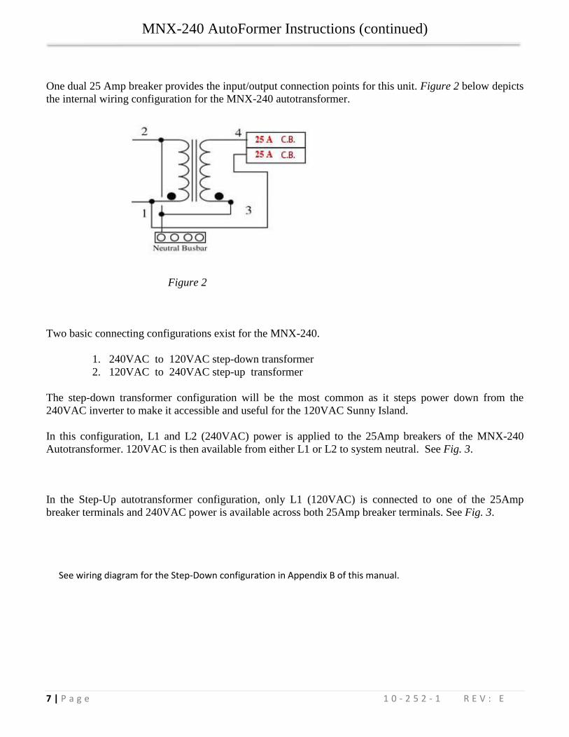
One dual 25 Amp breaker provides the input/output connection points for this unit. Figure 2 below depicts
the internal wiring configuration for the MNX-240 autotransformer.
Two basic connecting configurations exist for the MNX-240.
1. 240VAC to 120VAC step-down transformer
2. 120VAC to 240VAC step-up transformer
The step-down transformer configuration will be the most common as it steps power down from the
240VAC inverter to make it accessible and useful for the 120VAC Sunny Island.
In this configuration, L1 and L2 (240VAC) power is applied to the 25Amp breakers of the MNX-240
Autotransformer. 120VAC is then available from either L1 or L2 to system neutral. See Fig. 3.
In the Step-Up autotransformer configuration, only L1 (120VAC) is connected to one of the 25Amp
breaker terminals and 240VAC power is available across both 25Amp breaker terminals. See Fig. 3.
See wiring diagram for the Step-Down configuration in Appendix B of this manual.
Figure 2

MNX-240 AutoFormer Instructions (continued)
8 | P a g e 1 0 - 2 5 2 - 1 R E V : E
Figure 3
Wiring
Attention:
All AC wiring to the circuit breaker terminals are to be torque to 20 in-lbs. Wiring to these terminals must
meet the requirements set by the National Electrical Code® ANSI/NFPA 70. AC wiring must be copper wire
and rated for 75°C or higher and must be 10AWG minimum. Use copper Or Aluminum Conductors rated for
25 amps continuous minimum
Torque Specs
Each terminal must meet the required torque specification per NEC standard. For all breakers rated for
10AWG, the torque spec must be within 20 in-lbs of pressure. The 25Amp breakers provided with this unit
are rated for 20 in-lbs of pressure.
The bus bar terminal uses two distinct holes for varying sized wire. The larger hole, or the “main hole,” is
used for wire sized at 1/0 to 4 AWG, and requires that no less than 45 in-lbs of torque. The smaller hole, or
“tap hole,” is used for all wire smaller than 4AWG. The following chart illustrates the relation between wire
AWG and the associated torque: See table on Page 8.

MNX-240 AutoFormer Instructions (continued)
9 | P a g e 1 0 - 2 5 2 - 1 R E V : E
Small Bus Screw Large Bus Screw
18-10 AWG 40 in-lbs 8 AWG 40 in-lbs
8 AWG 25 in-lbs 6-4 AWG 45 in-lbs
6 AWG 35 in-lbs 3-1/0 AWG 50 in-lbs
Mechanical Installation
Mounting the Midnite Solar SMA MNX-240 Autotransformer is fast and easy. Follow the directions
below for a quick installation.
Note: Two mounting configurations exist for the Midnite Solar SMA MNX-240 Autotransformer. The
first belongs to our Stand Alone Mounting Assembly. This comes completely assembled and ready to
mount to a wall using its own mounting back plate. Please refer to Fig. 5a and Fig. 5b. The second
configuration mounts directly to the tall metal back plate. This configuration comes with the Midnite Solar
SMA AC Coupled System, in which the mounting back plate is large enough to accommodate the
inverter, e-panel, and autotransformer at the same time. Please refer to Fig. 6.

MNX-240 AutoFormer Instructions (continued)
10 | P a g e 1 0 - 2 5 2 - 1 R E V : E
Take Extra Care:
This unit weighs approximately 90-100 pounds and can be difficult to mount. It is recommended that no
less than 2 people be present in the mounting process.
System Orientation:
As you begin the mounting process you will need to know exactly where this unit will be placed in
relation to the E-panel and inverter system. When using the MNX-240 in conjunction with the Midnite
Solar SMA AC Coupled System, the autotransformer will be mounted at the top end of the mounting back
plate, just above the system inverter. When mounting the MNX-240 Stand Alone Autotransformer, orient
the autotransformer so that the system inverter and e-panels are within connecting range. Be sure to mount
the autotransformer to a strong and sturdy surface and fasten the mounting screws secure enough to
manage the weight. Use four ¼-20 x 1.5” screws. Make certain that the breaker switches are easily
accessible. This unit can be mounted on either a vertical or horizontal surface. Also, be aware that this unit
will need to be well ventilated. Be sure that there is at least an 8 inch space between the louvers and the
nearest obstruction.
Hardware and Tools:
Fig. 5a Fig. 5b
Fig. 6
Space louvers 8” away from any obstructions.

MNX-240 AutoFormer Instructions (continued)
11 | P a g e 1 0 - 2 5 2 - 1 R E V : E
Below are the necessary components needed to mount the Midnite Solar SMA MNX-240 Stand-Alone AC
Coupled Autotransformer to the MidNite tall metal back plate. In the Autoformer box you will find the
individual components listed here.
Hardware: Packet A Autoformer chassis mounting screws 10-32 x ½”
1 MNX-240 Autotransformer
1 Midnite Solar SMA Autoformer Lid
As any job requires, you will need the right tools. The Following is a list of tools you will need to properly
assemble the stand-alone Midnite Solar SMA MNX-240 Autotransformer. All tools needed to complete
the assembly will not be included with the assembly kit.
Tools:
#2 Philips head screwdriver (preferably electric).
Wire strippers,
conduit tools may be required
Mounting:
When mounting this unit to the Midnite Solar SMA AC Coupled System follow the steps below. There are three steps in mounting the Autoformer to the back plate of the Midnite Solar SMA AC Coupled
System: 1) remove the front cover, 2) mount the Autoformer 3) fasten the Autoformer lid.
Mount the Autoformer
To mount the Autoformer you will need the following:
MNX-240 Autotransformer
Autoformer Mount Assembly (Packet #4A)
1/2” Nut Driver
Procedure:
1. Orient and align the autotransformer over the Autoformer mounting holes located on the back plate
within the center of the Autoformer chassis mount.
2. Install four 10-32 screws supplied to secure to the backplate.
Fasten Autoformer lid

MNX-240 AutoFormer Instructions (continued)
12 | P a g e 1 0 - 2 5 2 - 1 R E V : E
To fasten the Autoformer lid you will need the following:
Yellow Autoformer Lid
Lid Mounting Screws (Packet #4A)
Philips Head Screwdriver
Procedure:
1. Orient the lid so that the mounting holes align with the holes on the chassis.
2. Fasten Autoformer lid mounting screws. (Use a Philips head screwdriver.)
When mounting this unit to a surface other than the back plate of the Midnite Solar SMA AC Coupled System, simply remove
the front cover and fasten to the surface of your choice using the surface mounting holes located in each of the four corners of
the standalone autotransformer back plate. Use ¼-20 x 1.5” screws when mounting through sheetrock. 1” long screws when
mounting to wood.
Appendix A
MIDNITE SOLAR INC. LIMITED WARRANTY
MidNite Solar Power electronics, sheet metal enclosures and accessories MidNite Solar Inc. warrants to the original customer that its products shall be free from defects in materials and workmanship. This warranty will be valid for a period of five (5) years for all products except the MNKID Charge Controller which will be two (2) years. At its option, MidNite Solar will repair or replace at no charge any MidNite product that proves to be defective within such warranty period. This warranty shall not apply if the MidNite Solar product has been damaged by unreasonable use, accident, negligence, service or modification by anyone other than MidNite Solar, or by any other causes unrelated to materials and workmanship. The original consumer purchaser must retain original purchase receipt for proof of purchase as a condition precedent to warranty coverage. To receive in-warranty service, the defective product must be received no later than two (2) weeks after the end of the warranty period. The product must be accompanied by proof of purchase and Return Authorization (RA) number issued by MidNite Solar. For an RMA number contact MidNite Solar Inc., 17722 67
th Ave NE, Arlington, WA 98223 (360) 403-7207.
Purchasers must prepay all delivery costs or shipping charges to return any defective MidNite Solar product under this warranty policy. Except for the warranty that the products are made in accordance with, the specifications therefore supplied or agreed to by customer: MIDNITE SOLAR MAKES NO WARRANTY EXPRESSED OR IMPLIED, AND ANY IMPLIED WARRANTY OF MERCHANTABILITY OR FITNESS FOR A PARTICULAR PURPOSE WHICH EXCEEDS THE FOREGOING WARRANTY IS HEREBY DISCLAIMED BY MIDNITE SOLAR AND EXCLUDED FROM ANY AGREEMENT MADE BY ACCEPTANCE OF ANY ORDER PURSUANT TO THIS QUOTATION. MIDNITE SOLAR WILL NOT BE LIABLE FOR ANY CONSEQUENTIAL DAMAGES, LOSS OR EXPENSE ARISING IN CONNECTION WITH THE USE OF OR THE INABILITY TO USE ITS GOODS FOR ANY PURPOSE WHATSOEVER. MIDNITE SOLAR’S MAXIMUM LIABILITY SHALL NOT IN ANY CASE EXCEED THE CONTRACT PRICE FOR THE GOODS CLAIMED TO BE DEFECTIVE OR UNSUITABLE. Products will be considered accepted by customer unless written notice to the contrary is given to MidNite Solar within ten (10) days of such delivery to customer. MIDNITE SOLAR is not responsible for loss or damage to products owned by customer and located on MIDNITE SOLAR’S premises caused by fire or other casualties beyond MIDNITE SOLAR’s control. This warranty is in lieu of all other warranties expressed or implied. MIDNITE SOLAR INC. 17722 67
TH AVE NE ARLINGTON, WA 98223
Email: [email protected] PH: 360.403-7207 FAX: 360-691-6862

MNX-240 AutoFormer Instructions (continued)
13 | P a g e 1 0 - 2 5 2 - 1 R E V : E
Appendix B
Assembly Diagram:

MNX-240 AutoFormer Instructions (continued)
14 | P a g e 1 0 - 2 5 2 - 1 R E V : E
Appendix C
Wiring Diagram: