autroprime fire alarm control panel bs-200 · autroprime fire alarm control panel bs-200 autronica...
TRANSCRIPT
116-P-BS200/CGB Rev. A, 2008-03-07 Protecting life, environment and property...
Features • SelfVerify® function for automatic testing of detectors • Automatic setup • Automatic addressing of detectors • Two loops • USB for data transfer to/from memory stick • User-friendly display and operator controls • Back-lit operating buttons. Text display suitable for nighttime
operation • Surface mounting • Designed to meet EN 54 requirements and conforms to
CE standards • Complies with environmental conditions of IEC-721-3-3
class 3k5
Application/Description
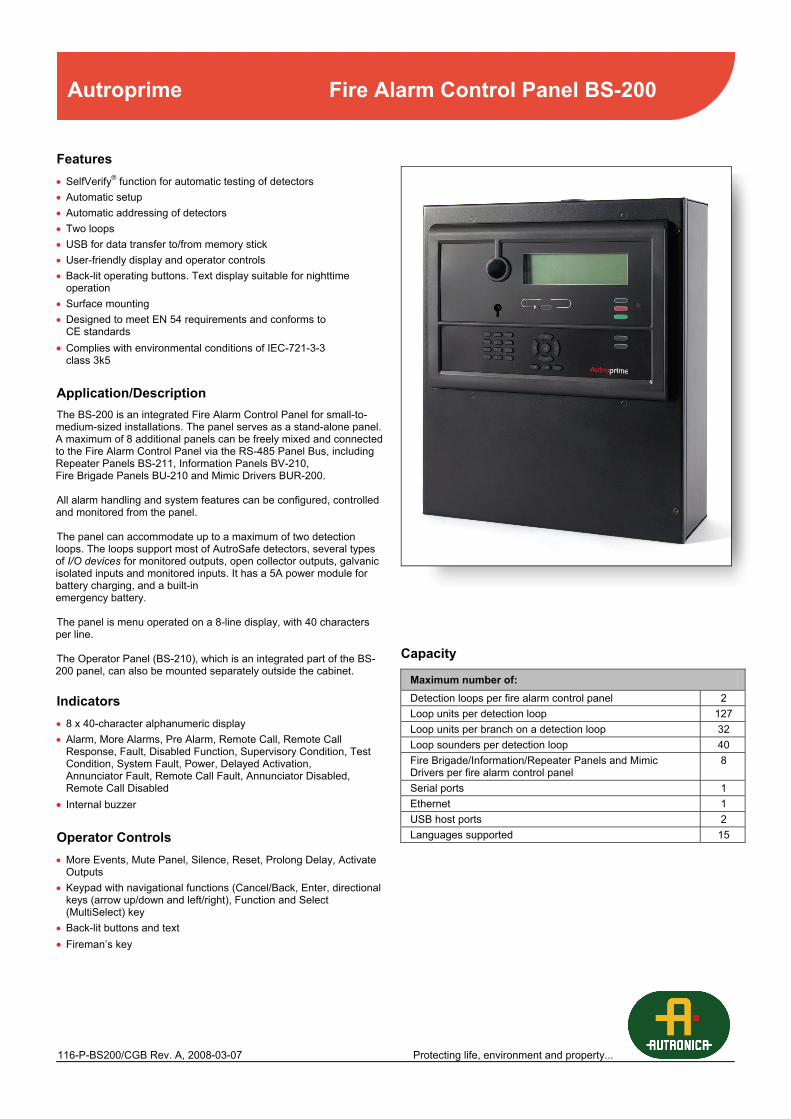
The BS-200 is an integrated Fire Alarm Control Panel for small-to-medium-sized installations. The panel serves as a stand-alone panel. A maximum of 8 additional panels can be freely mixed and connected to the Fire Alarm Control Panel via the RS-485 Panel Bus, including Repeater Panels BS-211, Information Panels BV-210, Fire Brigade Panels BU-210 and Mimic Drivers BUR-200. All alarm handling and system features can be configured, controlled and monitored from the panel. The panel can accommodate up to a maximum of two detection loops. The loops support most of AutroSafe detectors, several types of I/O devices for monitored outputs, open collector outputs, galvanic isolated inputs and monitored inputs. It has a 5A power module for battery charging, and a built-in emergency battery. The panel is menu operated on a 8-line display, with 40 characters per line. The Operator Panel (BS-210), which is an integrated part of the BS-200 panel, can also be mounted separately outside the cabinet.
Indicators • 8 x 40-character alphanumeric display • Alarm, More Alarms, Pre Alarm, Remote Call, Remote Call
Response, Fault, Disabled Function, Supervisory Condition, Test Condition, System Fault, Power, Delayed Activation, Annunciator Fault, Remote Call Fault, Annunciator Disabled, Remote Call Disabled
• Internal buzzer
Operator Controls • More Events, Mute Panel, Silence, Reset, Prolong Delay, Activate
Outputs • Keypad with navigational functions (Cancel/Back, Enter, directional
keys (arrow up/down and left/right), Function and Select (MultiSelect) key
• Back-lit buttons and text • Fireman’s key
Capacity
Maximum number of: Detection loops per fire alarm control panel 2 Loop units per detection loop 127 Loop units per branch on a detection loop 32 Loop sounders per detection loop 40 Fire Brigade/Information/Repeater Panels and Mimic Drivers per fire alarm control panel
8
Serial ports 1 Ethernet 1 USB host ports 2 Languages supported 15
Autroprime Fire Alarm Control Panel BS-200
Autroprime Fire Alarm Control Panel BS-200
AUTRONICA FIRE AND SECURITY AS Fire and Security, Trondheim, Norway Phone: +47 73 58 25 00, Fax: 73 58 25 01, e-mail: [email protected] Oil and Gas, Stavanger, Norway Phone: +47 51 84 09 00, Fax: +47 51 84 09 99 Maritime division, Spikkestad, Norway Phone: +47 31 29 55 00, Fax: +47 31 29 55 01
Visit Autronica Fire and Security AS’ website: www.autronicafire.com
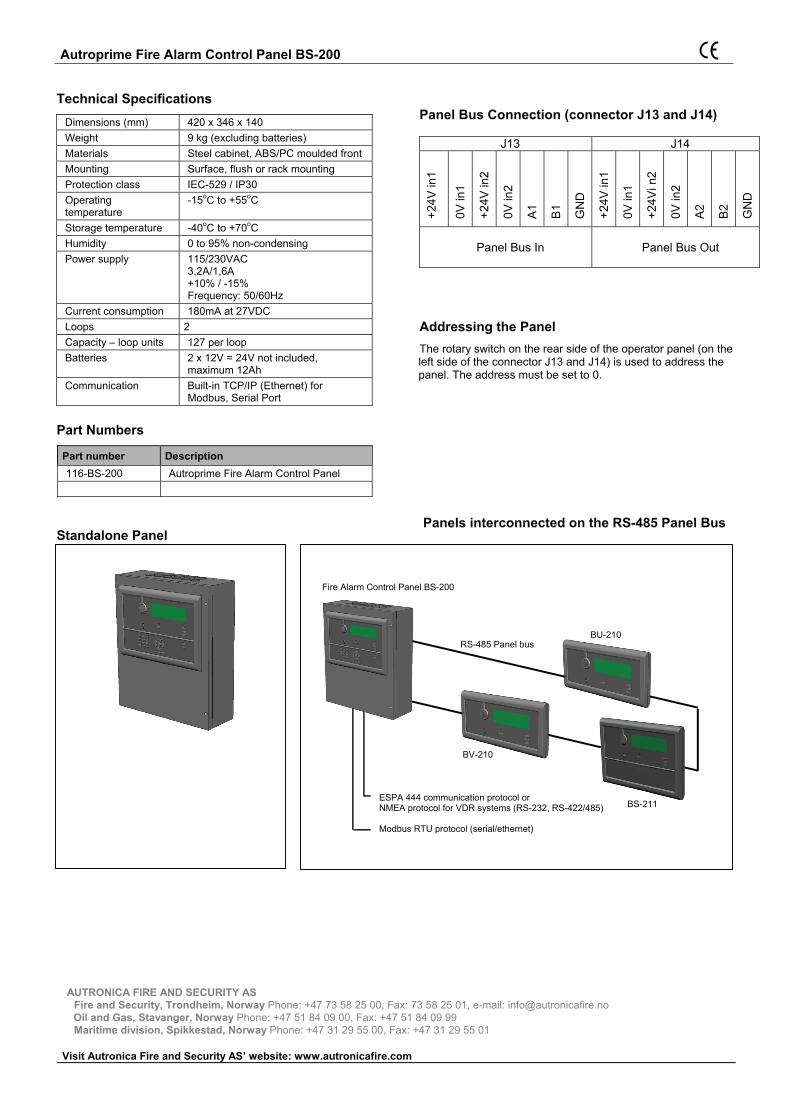
Fire Alarm Control Panel BS-200
ESPA 444 communication protocol or NMEA protocol for VDR systems (RS-232, RS-422/485) Modbus RTU protocol (serial/ethernet)
RS-485 Panel busBU-210
BS-211
BV-210
Technical Specifications Dimensions (mm) 420 x 346 x 140 Weight 9 kg (excluding batteries) Materials Steel cabinet, ABS/PC moulded front Mounting Surface, flush or rack mounting Protection class IEC-529 / IP30 Operating temperature
-15oC to +55oC
Storage temperature -40oC to +70oC Humidity 0 to 95% non-condensing Power supply 115/230VAC
3,2A/1,6A +10% / -15% Frequency: 50/60Hz
Current consumption 180mA at 27VDC Loops 2 Capacity – loop units 127 per loop Batteries 2 x 12V = 24V not included,
maximum 12Ah Communication Built-in TCP/IP (Ethernet) for
Modbus, Serial Port
Part Numbers
Part number Description 116-BS-200 Autroprime Fire Alarm Control Panel
Standalone Panel
Panel Bus Connection (connector J13 and J14)
Addressing the Panel The rotary switch on the rear side of the operator panel (on the left side of the connector J13 and J14) is used to address the panel. The address must be set to 0.
Panels interconnected on the RS-485 Panel Bus
J13 J14
+24V
in1
0V in
1
+24V
in2
0V in
2
A1
B1
GN
D
+24V
in1
0V in
1
+24V
i n2
0V in
2
A2
B2
GN
D
Panel Bus In Panel Bus Out