av-30-e installation manual
TRANSCRIPT
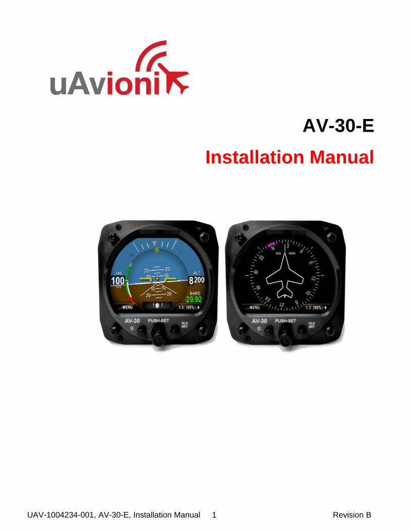
UAV-1004234-001, AV-30-E, Installation Manual 1 Revision B
AV-30-E
Installation Manual
UAV-1004234-001, AV-30-E, Installation Manual 2 Revision B
© 2020 uAvionix Corporation. All rights reserved.
Except as expressly provided herein, no part of this guide may be
reproduced, transmitted, disseminated, downloaded or stored in any
storage medium, for any purpose without the express written permission
of uAvionix. uAvionix grants permissions to download a single copy of
this guide onto an electronic storage medium to be viewed for personal
use, provided that the complete text of this copyright notice is retained.
Unauthorized commercial distribution of this manual or any revision
hereto is strictly prohibited.
uAvionix® and Ping® are registered trademarks of uAvionix Corporation
and may not be used without express permission of uAvionix.
AV-30, AV-30-E, and AV-30-C are trademarks of uAvionix Corporation
and may not be used without express permission of uAvionix.
Patent uavionix.com/patents

UAV-1004234-001, AV-30-E, Installation Manual 3 Revision B
1 Revision History
Revision Date Comments
A 6/2/2020 Initial release
B 1/12/2021 Software update 1.1.0

UAV-1004234-001, AV-30-E, Installation Manual 4 Revision B
2 Warnings / Disclaimers
All device operational procedures must be learned on the ground.
uAvionix is not liable for damages arising from the use or misuse of this
product.
This equipment is classified by the United States Department of
Commerce's Bureau of Industry and Security (BIS) as Export Control
Classification Number (ECCN) 7A994.
These items are controlled by the U.S. Government and authorized for
export only to the country of ultimate destination for use by the ultimate
consignee or end-user(s) herein identified. They may not be resold,
transferred, or otherwise disposed of, to any other country or to any
person other than the authorized ultimate consignee or end-user(s),
either in their original form or after being incorporated into other items,
without first obtaining approval from the U.S. government or as otherwise
authorized by U.S. law and regulations.

UAV-1004234-001, AV-30-E, Installation Manual 5 Revision B
3 Table of Contents
1 Revision History .............................................................................. 3
2 Warnings / Disclaimers .................................................................... 4
3 Table of Contents ............................................................................ 5
4 AV-30-E System Information ........................................................... 7
4.1 System Description .................................................................... 7
4.2 System Functions ...................................................................... 9
4.3 System Specifications .............................................................. 10
5 Design Standards .......................................................................... 11
5.1 Applicable Performance Standards .......................................... 12
6 Installation Locations & Operating Modes ..................................... 13
6.1 Installation Locations ............................................................... 13
6.2 Operating Mode Configuration ................................................. 13
7 Functionality and Required Interfaces ........................................... 14
7.1 Aircraft Systems Connections .................................................. 14
7.2 Feature Matrix ......................................................................... 15
7.2.1 Power Input (Required) ...................................................... 16
7.2.2 Pitot and Static Interfaces (Required/Optional) .................. 16
7.2.3 Outside Air Temp Input (Optional) ...................................... 16
7.2.4 Audio Output (Optional) ..................................................... 17
7.2.5 GPS Interface (Optional) .................................................... 17
7.2.6 tailBeaconX Control (optional) ............................................ 18
7.3 Internal Battery Operation ........................................................ 18
7.3.1 General .............................................................................. 18
8 Equipment Installation ................................................................... 19
8.1 Overview .................................................................................. 19
8.2 Supplied Components ............................................................. 19
8.3 Non-Supplied Components ...................................................... 19
8.4 Mechanical Drawing ................................................................ 20
8.5 Mounting Screw Length Restriction ......................................... 21
8.6 Wiring Diagrams ...................................................................... 22
8.7 Bonding Requirements ............................................................ 24
8.8 Unit Pinout ............................................................................... 25
9 Setup & Configuration ................................................................... 26
9.1 Startup and Common Controls................................................. 26
9.2 Available Menus ...................................................................... 27
9.3 Install Menu Activation ............................................................. 28

UAV-1004234-001, AV-30-E, Installation Manual 6 Revision B
9.4 Install Menu Settings ............................................................... 29
9.5 Mandatory Settings .................................................................. 30
9.5.1 Unit Function ...................................................................... 30
9.5.2 Function Lock ..................................................................... 30
9.5.3 Trims .................................................................................. 30
9.5.4 V-Speeds ........................................................................... 30
9.5.5 Display Units ...................................................................... 30
9.5.6 Serial Inputs ....................................................................... 31
9.5.7 Demo Mode ....................................................................... 31
9.6 System Checkout ..................................................................... 31
9.6.1 Alignment ........................................................................... 31
9.6.2 OAT Interface ..................................................................... 32
9.6.3 GPS Navigator Interface .................................................... 34
9.6.4 tailBeaconX control Interface ............................................. 35
10 Troubleshooting ......................................................................... 37
11 Serial Interface Specification ...................................................... 38
12 Field Update Capability .............................................................. 39

UAV-1004234-001, AV-30-E, Installation Manual 7 Revision B
4 AV-30-E System Information
4.1 System Description
The uAvionix AV-30-E is a fully digital multi-mode instrument that
mounts in the legacy 3 1/8” round instrument panel. It can be field
configured as either an Attitude Indicator (AI) or a Directional Gyro
(DG) indicator. It is fully self-contained with dual-precision inertial and
pressure sensors and allows for a wide variety of pilot customization.
Figure 1 - AV-30-E Multi Mode AI/DG – Basic Display
When configured as an AI, primary attitude and slip are always
displayed. The un-used portions of the display area can be customized
by the pilot to show a variety of textual and graphical data-overlay
fields. Three pages may be customized by the pilot while a fourth page
presents a fully decluttered view of only attitude and slip.
When configured as a Directional Gyro (DG), direction of flight
information is presented. The flight direction can be configured to be
presented as non-slaved heading or inertially stabilized GPS track
when connected to an external GPS navigator. Multiple display
presentations, including compass rose, GPS HSI, and GPS Arc views
can be selected by the pilot. The un-used portions of the display area
can similarly be configured for a variety of textual data-overlays.
In both operating modes, the pilot may select from multiple visual styles
which are intended to improve visual compatibility with legacy aircraft
instrumentation and preserve the look-and-feel of older aircraft
applications.

UAV-1004234-001, AV-30-E, Installation Manual 8 Revision B
A wide variety of supplemental functions, including audio alerting,
derived angle of attack presentation, g-load display, and more are
provided. An internal, rechargeable LiPo battery allows for operation
for a nominal 2 hours in the event of aircraft power loss and 30 minutes
minimum under all temperature conditions.

UAV-1004234-001, AV-30-E, Installation Manual 9 Revision B
4.2 System Functions
Primary Functions:
- Primary Attitude (AI Mode)
- Primary Slip (AI Mode)
- Primary Direction of Flight Indication (DG Mode)
Supplemental Functions:
- Indicated Airspeed
- Altitude
- V-Speeds
- Angle of Attack
- Vertical Trend
- Vertical Speed
- Set Altitude
- Heading
- Bus Voltage
- G Load
- Outside Air Temp
- True Airspeed
- Density Altitude
- GPS Navigator / Waypoint Data
- GPS Navigator Nav Data
- GPS Navigator Route Line
- Heading Bug
Audio and Visual Alerting Functions:
- AoA Alerting
- G Limit Alerting
- Excessive Roll Alerting
Misc. Functions:
- Internal Battery Operation
- Auto / Manual Brightness

UAV-1004234-001, AV-30-E, Installation Manual 10 Revision B
4.3 System Specifications
Electrical Attributes
Input Voltage Nominal +10 to +32 VDC
Input Voltage Max +60 VDC
Input Power Nominal 6 Watts (0.5 Amps @ 12VDC)
Input Power Max 12 Watts (1.0 Amps @ 12VDC)
Required Circuit Breaker 2 Amp
Operation on Battery 2 Hrs Typ @ 20°C / 30 Min Minimum @ -20C
Physical Attributes
Mounting Configuration 3 1/8” Round Instrument Hole
Dimensions wo/Connector 3.38 x 3.38 x 1.6 Inches
Weight 0.56 Lbs.
Electrical Connector 15 Pin Male D-Sub
Pneumatic Connectors ¼” OD Quick Connect
Mounting (4X) #6-32 Machine Screws
Case Material Billet Aluminum
Environmental
Ground Survival Low -55°C
Operating Low -20°C
Ground Survival High +85°C
Operating High +55°C
Altitude 25,000 Feet Max
Optical Characteristics
Diagonal Size 3” Circular
Contrast Ratio (Typical) 500
Brightness (Typical) 1000 cd/m2
Viewing Angle Left/Right 60°
Viewing Angle Up 45°
Viewing Angle Down 10°
Backlight Lifetime (Typical) 50,000 Hrs
Table 1 - System Specifications

UAV-1004234-001, AV-30-E, Installation Manual 11 Revision B
5 Design Standards
This installation manual provides mechanical and electrical information
necessary to install the AV-30-E. The content of this manual assumes
use by competent and qualified personnel using standard maintenance
procedures in accordance with Title 14 of the Code of Federal
Regulation (CFR) and other related accepted procedures.
The design basis for the AV-30-E is 14 CFR Part 23, Amendment 23-61.
Installation is approved as a Level A system and is robust to High
Intensity Radiated Field (HIRF) and lightning levels applicable for both
metallic and non-metallic aircraft.
The installer must ensure that all installation limitations as
defined in this document are observed.
The internal battery capacity has been tested and verified to provide 30
minutes of operational capacity (with reserve), and meets the
requirements defined in CFR 23.1311(a)(5) and 23.1353(h), allowing
independent operation from the primary electrical power system.
See Section 7.2.6 tailBeaconX Control (optional)
The AV-30-E has the capability of being the transponder control
interface for an installed tailBeaconX. This requires an RS-232 serial
connection from the tailBeaconX to the AV-30-E. tailBeaconX can
also supply GPS source information to the AV-30-E using the
existing serial connection.
Internal Battery Operation for additional battery operational
characteristics.

UAV-1004234-001, AV-30-E, Installation Manual 12 Revision B
5.1 Applicable Performance Standards
The AV-30-E was designed to, and satisfied the applicable
performance requirements defined in the following design standards:
MOPS Title Category
SAE AS8019 Airspeed Instruments Type B
SAE AS392C Altimeter, Pressure Actuated, Sensitive Type
Type I
SAE AS8005A Standard Temperature Instruments Class IIIc
SAE AS8034 Airborne Multipurpose Electronic Displays N/A
RTCA DO-334 Attitude and Heading Reference Systems (AHRS)
A5 H9 T7
ASTM F3011-13 Angle Of Attack System N/A
RTCA DO-347 Cert and Test for Small and Med Lipo Batteries
Medium Size
Table 2 - Applicable Performance Standards

UAV-1004234-001, AV-30-E, Installation Manual 13 Revision B
6 Installation Locations & Operating Modes
6.1 Installation Locations
The following figure shows a typical “six-pack” and one possible
arrangement of instrument locations:
AI
DG AI/DG
Figure 2 – Mechanical Gauge Replacement
Note that the physical arrangement in many aircraft varies from the
traditional “T” configuration shown above. The AI/DG locations are
examples of installation locations as a non-required instrument.
The existing mechanically based altimeter and airspeed
indicator must remain in their factory locations for this
installation configuration.
6.2 Operating Mode Configuration
The AV-30-E operating mode is configured during installation and can
be set as follows:
Unit locked as a dedicated Attitude Indicator (AI Mode)
Unit locked as a dedicated Direction Indicator (DG Mode)
Unit can be toggled between AI and DG mode by the pilot
If the functionality is not locked, pressing and holding the rotary knob
will toggle between AI and DG mode.

UAV-1004234-001, AV-30-E, Installation Manual 14 Revision B
7 Functionality and Required Interfaces
7.1 Aircraft Systems Connections
All aircraft systems connections are provided on the single 15-Pin D-
sub connector and two quick-connect pneumatic fittings. Various
interfaces are optional as indicated in the following diagrams.
Aircraft Power
Pitot System
Static System
ELEC
TRIC
AL
INTE
RFA
CES
Digital
Optional OAT ProbeAnalog
Optional Audio OutAnalog
AIRCRAFT SYSTEMS
Optional GPS Navigator
AV-30-C
PN
EUM
ATI
C
CO
NN
ECTO
RS
Figure 3 – AV-30-E Aircraft Systems Interfaces – AI Mode
Figure 4 – AV-30-E Aircraft Systems Interfaces – DG Mode
Aircraft Power
Optional Pitot System
Optional Static System
ELEC
TRIC
AL
INTE
RFA
CES
Digital
Optional OAT ProbeAnalog
AIRCRAFT SYSTEMS
Optional GPS Navigator
AV-30-C
PN
EUM
ATI
C
CO
NN
ECTO
RS
Optional Audio OutAnalog
Audio Output Not Supported In DG Mode
UAV-1004234-001, AV-30-E, Installation Manual 15 Revision B
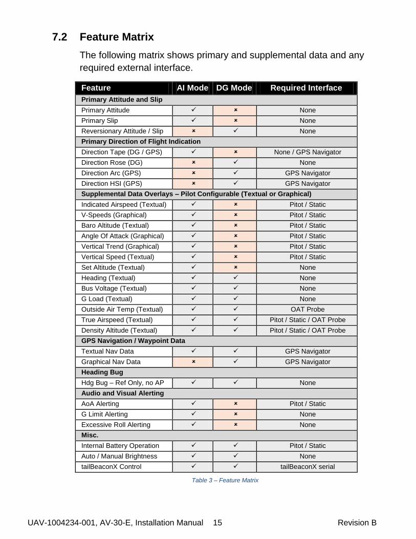
7.2 Feature Matrix
The following matrix shows primary and supplemental data and any
required external interface.
Feature AI Mode DG Mode Required Interface
Primary Attitude and Slip
Primary Attitude None
Primary Slip None
Reversionary Attitude / Slip None
Primary Direction of Flight Indication
Direction Tape (DG / GPS) None / GPS Navigator
Direction Rose (DG) None
Direction Arc (GPS) GPS Navigator
Direction HSI (GPS) GPS Navigator
Supplemental Data Overlays – Pilot Configurable (Textual or Graphical)
Indicated Airspeed (Textual) Pitot / Static
V-Speeds (Graphical) Pitot / Static
Baro Altitude (Textual) Pitot / Static
Angle Of Attack (Graphical) Pitot / Static
Vertical Trend (Graphical) Pitot / Static
Vertical Speed (Textual) Pitot / Static
Set Altitude (Textual) None
Heading (Textual) None
Bus Voltage (Textual) None
G Load (Textual) None
Outside Air Temp (Textual) OAT Probe
True Airspeed (Textual) Pitot / Static / OAT Probe
Density Altitude (Textual) Pitot / Static / OAT Probe
GPS Navigation / Waypoint Data
Textual Nav Data GPS Navigator
Graphical Nav Data GPS Navigator
Heading Bug
Hdg Bug – Ref Only, no AP None
Audio and Visual Alerting
AoA Alerting Pitot / Static
G Limit Alerting None
Excessive Roll Alerting None
Misc.
Internal Battery Operation Pitot / Static
Auto / Manual Brightness None
tailBeaconX Control tailBeaconX serial
Table 3 – Feature Matrix
UAV-1004234-001, AV-30-E, Installation Manual 16 Revision B
7.2.1 Power Input (Required)
Power input is required and connects to the aircraft’s power bus.
Input range is compatible with both 12V and 24V aircraft. Internally,
this power is diode OR’ed with the internal battery via a processor-
controlled switch. This architecture allows the unit to continue
operation if external power fluctuates or is completely lost.
Each AV-30-E must have a dedicated, properly labeled, pilot
resettable circuit breaker as part of the installation. Power for the
unit may be supplied from either the avionics bus or the main battery
master relay.
7.2.2 Pitot and Static Interfaces (Required/Optional)
In addition to directly displayable data such as airspeed and altitude,
pitot and static inputs are utilized within the probeless Angle of
Attack algorithm and provide the underlying source for various air-
data type data overlays (TAS & DALT).
When installed as a DG, pitot and static connections are not required
unless TAS and DALT are desirable (also requires a dedicated OAT
probe). See the detailed wiring diagram for more information.
7.2.3 Outside Air Temp Input (Optional)
The optional outside air temperature interface requires a dedicated
external analog probe. This port connection is compatible with the
Davtron P/N C307PS (not supplied).
This is a differential two-wire current source based on the Analog
Devices AD590KH component and supplies a current that
corresponds to the ambient temperature.
If two displays are connected to the same probe, the current
will be split between the two and incorrect readings will be
shown by both.
The sensor reading must be trimmed during the installation process
to compensate for probe-to-probe variations.

UAV-1004234-001, AV-30-E, Installation Manual 17 Revision B
The OAT probe is automatically detected by the system, and when
detected, allows temperature related parameters to be selected for
display by the pilot.
If the OAT probe is not detected, display of these parameters will
automatically be inhibited.
7.2.4 Audio Output (Optional)
The optional audio panel connection is a low-voltage analog output
that is designed to connect directly to an audio panel (typically a
non-switched input). High power outputs capable of directly driving a
cockpit speaker are not provided.
When installed as a DG, no audio alerting is supported, and this
output should remain disconnected.
In non-metallic, IFR capable aircraft, this connection MUST
remain disconnected due to lightning strike limitations.
7.2.5 GPS Interface (Optional)
The GPS interface is an optional RS-232 serial input that is
compatible with the industry standard “Moving Map” output provided
by most panel mounted GPS units, and NMEA serial interfaces
provided by most hand-held GPS units.
This is a text/binary protocol output by the GPS navigator that
contains situational awareness information such as ground speed,
track, distance to destination, cross track, etc, and is typically utilized
by remote mapping/display products to provide additional pilot
awareness.
This output does not provide IFR compliant lateral or vertical
guidance, therefore all deviation related data presented is for VFR
operations only.
The AV-30-E does no computations or operations on the data
obtained from the GPS navigator, and simply displays the received
data in a textual or graphical format as configured by the pilot.

UAV-1004234-001, AV-30-E, Installation Manual 18 Revision B
This serial interface may be connected in parallel between
multiple AV-30 units and is supported in both the AI and DG
modes.
The supported protocols are contained in Section 11- Serial Interface
Specification.
7.2.6 tailBeaconX Control (optional)
The AV-30-E has the capability of being the transponder control
interface for an installed tailBeaconX. This requires an RS-232 serial
connection from the tailBeaconX to the AV-30-E. tailBeaconX can
also supply GPS source information to the AV-30-E using the
existing serial connection.
7.3 Internal Battery Operation
7.3.1 General
The internal battery consists of a rechargeable LiPo battery system
with automatic recharge, self-test and power switching capability.
The internal battery capacity will provide approximately 2 hours of
operation at standard temperatures and 30 minutes (minimum) of
operational capacity over the operational temperature range.
See the Internal Battery Operation section within the Pilots Guide for
additional operational information.

UAV-1004234-001, AV-30-E, Installation Manual 19 Revision B
8 Equipment Installation
8.1 Overview
Installation consists of the following steps:
Remove / relocate any legacy instrumentation
Add or locate an appropriate power source / breaker
Wire power and systems interfaces as needed
Mount the unit to the instrument panel with supplied screws
Apply power and perform setup
8.2 Supplied Components
Component Part Number Description
AV-30-E Unit UAV-1003429-001 AV-30-E Unit
AV-30-E Installation Kit
UAV-1004091-001 Installation Kit
Table 4 – Supplied Components
8.3 Non-Supplied Components
Component Description Pitot / Static Tubing Length as required
Pitot Static T’s Quantity as required
Circuit Breakers (2A) One required for each instrument
OAT Probe Davtron P/N C307PS
Table 5 – Non-Supplied Components

UAV-1004234-001, AV-30-E, Installation Manual 20 Revision B
8.4 Mechanical Drawing
Figure 5 – Mechanical Drawing

UAV-1004234-001, AV-30-E, Installation Manual 21 Revision B
8.5 Mounting Screw Length Restriction
The AV-30-E is fastened to the instrument panel with four 6-32 screws.
The unit mounts from the rear of the instrument panel, with the screws
being inserted from the front of the panel.
The four 6-32 Mounting screws must observe depth limits given
the internal component design.
Torque screws to 6 (+/-1) Inch LBS.
The threaded hole in the AV-30-E bottoms out prior to the internal
components. Installing a mounting screw that is longer than optimal will
not damage the unit but will result in the unit not being fully fastened to
the panel.
Mounting Screw
Optional Spacing Washer
Instrument Panel
Internal Components
Figure 6 – Mounting Screw Dept Limits
The installation kit contains multiple length screws to assist in
compensating for different instrument panel thicknesses.
UAV-1004234-001, AV-30-E, Installation Manual 22 Revision B
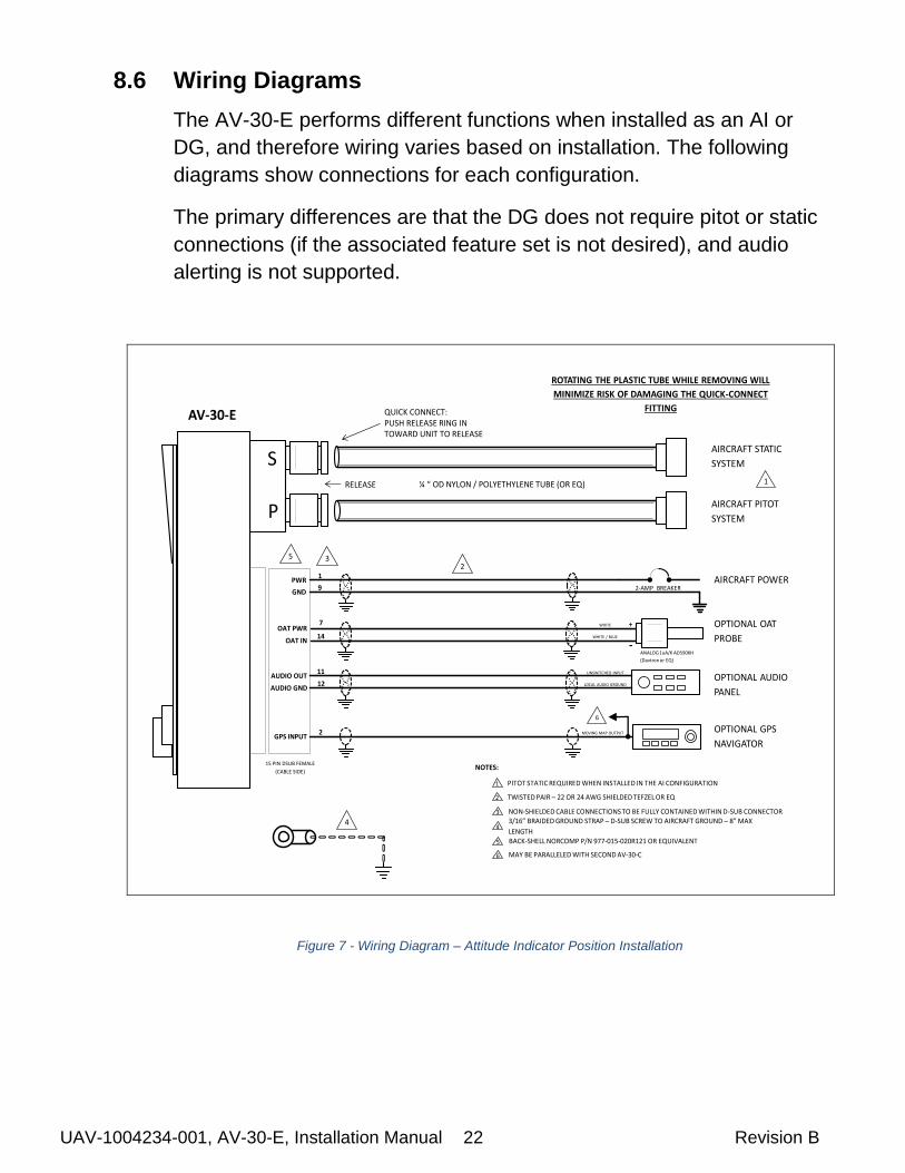
8.6 Wiring Diagrams
The AV-30-E performs different functions when installed as an AI or
DG, and therefore wiring varies based on installation. The following
diagrams show connections for each configuration.
The primary differences are that the DG does not require pitot or static
connections (if the associated feature set is not desired), and audio
alerting is not supported.
AIRCRAFT STATIC
SYSTEM
QUICK CONNECT:PUSH RELEASE RING IN TOWARD UNIT TO RELEASE
2-AMP BREAKER
RELEASE
AIRCRAFT PITOT
SYSTEM
S
P
AIRCRAFT POWER
OPTIONAL OAT
PROBE
OPTIONAL GPS
NAVIGATOR
OPTIONAL AUDIO
PANEL
¼ “ OD NYLON / POLYETHYLENE TUBE (OR EQ)
+
-ANALOG 1uA/K AD590KH
(Davtron or EQ)
UNSWITCHED INPUT
ROTATING THE PLASTIC TUBE WHILE REMOVING WILL
MINIMIZE RISK OF DAMAGING THE QUICK-CONNECT
FITTING
AV-20
LOCAL AUDIO GROUND
MOVING MAP OUTPUT
6
AV-30-E
PWR1
GND9
OAT PWR7
OAT IN14
WHITE
WHITE / BLUE
AUDIO OUT11
AUDIO GND12
GPS INPUT2
15 PIN DSUB FEMALE
(CABLE SIDE)
1
2
3/16” BRAIDED GROUND STRAP – D-SUB SCREW TO AIRCRAFT GROUND – 8” MAX
LENGTH
NON-SHIELDED CABLE CONNECTIONS TO BE FULLY CONTAINED WITHIN D-SUB CONNECTOR
TWISTED PAIR – 22 OR 24 AWG SHIELDED TEFZEL OR EQ
3
2
4
NOTES:
BACK-SHELL NORCOMP P/N 977-015-020R121 OR EQUIVALENT5
3
PITOT STATIC REQUIRED WHEN INSTALLED IN THE AI CONFIGURATION1
4
5
MAY BE PARALLELED WITH SECOND AV-30-C6
Figure 7 - Wiring Diagram – Attitude Indicator Position Installation

UAV-1004234-001, AV-30-E, Installation Manual 23 Revision B
OPTIONAL AIRCRAFT
STATIC SYSTEM
QUICK CONNECT:PUSH RELEASE RING IN TOWARD UNIT TO RELEASE
2-AMP BREAKER
RELEASE
OPTIONAL AIRCRAFT
PITOT SYSTEM
S
P
AIRCRAFT POWER
OPTIONAL OAT
PROBE
OPTIONAL GPS
NAVIGATOR
¼ “ OD NYLON / POLYETHYLENE TUBE (OR EQ)
+
-ANALOG 1uA/K AD590KH
(Davtron or EQ)
ROTATING THE PLASTIC TUBE WHILE REMOVING WILL
MINIMIZE RISK OF DAMAGING THE QUICK-CONNECT
FITTING
AV-20
MOVING MAP OUTPUT
6
AV-30-E
PWR1
GND9
OAT PWR7
OAT IN14
WHITE
WHITE / BLUE
AUDIO OUT11
AUDIO GND12
GPS INPUT2
15 PIN DSUB FEMALE
(CABLE SIDE)
2
3/16” BRAIDED GROUND STRAP – D-SUB SCREW TO AIRCRAFT GROUND – 8” MAX
LENGTH
NON-SHIELDED CABLE CONNECTIONS TO BE FULLY CONTAINED WITHIN D-SUB CONNECTOR
TWISTED PAIR – 22 OR 24 AWG SHIELDED TEFZEL OR EQ
3
2
4
NOTES:
BACK-SHELL NORCOMP P/N 977-015-020R121 OR EQUIVALENT5
3
FOR DALT, TAS, OAT FUNCTIONALITY, PITOT, STATIC AND OAT MUST ALL BE CONNECTED 1
4
5
MAY BE PARALLELED WITH SECOND AV-30-C6
1
AUDIO ALERTS NOT SUPPORTED WHEN INSTALLED AS DG – DO NOT CONNECT7
7
Figure 8 - Wiring Diagram – DG Position Installation
Figure 9 - Wiring Diagram - tailBeaconX Installation

UAV-1004234-001, AV-30-E, Installation Manual 24 Revision B
8.7 Bonding Requirements
The following figure shows the grounding requirements for the
electrical connections. The two D-Sub screws are to be utilized for
shield and ground strap connections. The supplied ring terminal
connectors are sized for these screws. The ground braid strap is to be
less than 8 inches in overall length and at least 3/16 width. Alpha Wire
part number 1230 SV001 or equivalent.
Figure 10 - Ground Braid Strap – 8” or Less in Length
The exposed (non-shielded) portions of the interface cables AND the
ground drains are to remain less than 2.5 inches.
2.5 Inches Maximum
Non ShieldedShielded
The bond between the unit (measured at the D-sub screws) to the aircraft
frame must be 2.5 milli-Ohms or less
GROUND
STRAP
< 8”
AIRCRAFT
GROUNDCABLE SHIELD DRAIN
< 2.5”
D-SUB BACK-SHELL
Figure 11 –Cable Shields and Ground Strap
UAV-1004234-001, AV-30-E, Installation Manual 25 Revision B
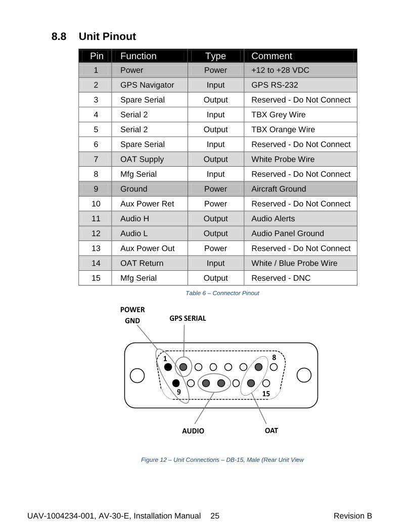
8.8 Unit Pinout
Pin Function Type Comment
1 Power Power +12 to +28 VDC
2 GPS Navigator Input GPS RS-232
3 Spare Serial Output Reserved - Do Not Connect
4 Serial 2 Input TBX Grey Wire
5 Serial 2 Output TBX Orange Wire
6 Spare Serial Input Reserved - Do Not Connect
7 OAT Supply Output White Probe Wire
8 Mfg Serial Input Reserved - Do Not Connect
9 Ground Power Aircraft Ground
10 Aux Power Ret Power Reserved - Do Not Connect
11 Audio H Output Audio Alerts
12 Audio L Output Audio Panel Ground
13 Aux Power Out Power Reserved - Do Not Connect
14 OAT Return Input White / Blue Probe Wire
15 Mfg Serial Output Reserved - DNC
Table 6 – Connector Pinout
1 8
9 15
POWER
GND GPS SERIAL
AUDIO OAT
Figure 12 – Unit Connections – DB-15, Male (Rear Unit View
UAV-1004234-001, AV-30-E, Installation Manual 26 Revision B
9 Setup & Configuration
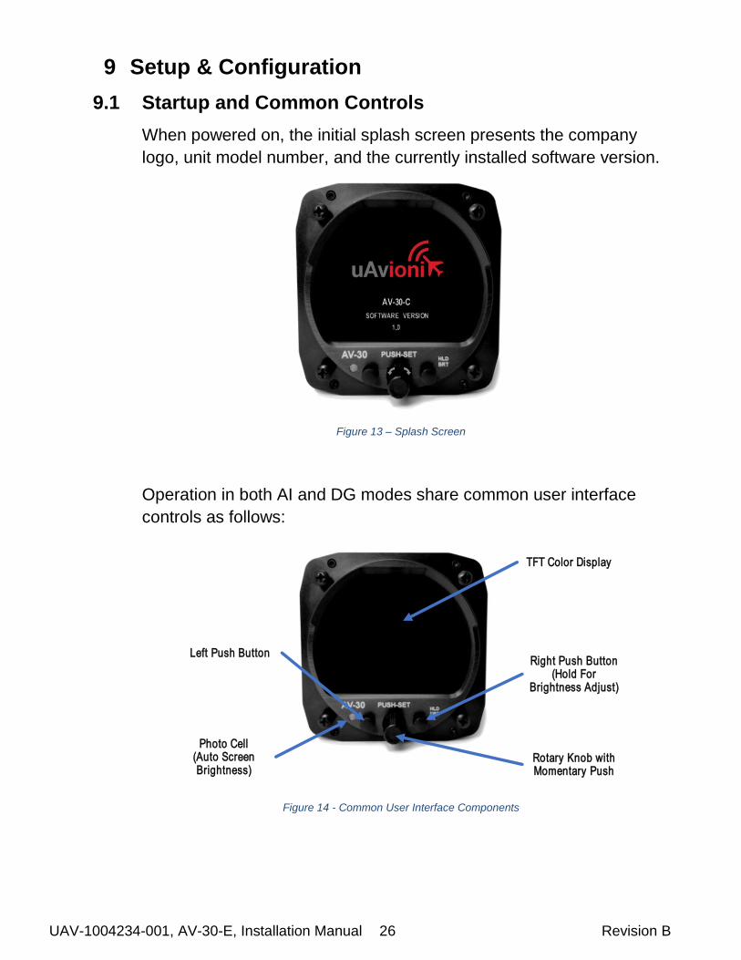
9.1 Startup and Common Controls
When powered on, the initial splash screen presents the company
logo, unit model number, and the currently installed software version.
Figure 13 – Splash Screen
Operation in both AI and DG modes share common user interface
controls as follows:
Rotary Knob with Momentary Push
Left Push ButtonRight Push Button
(Hold ForBrightness Adjust)
Photo Cell(Auto Screen Brightness)
TFT Color Display
Figure 14 - Common User Interface Components

UAV-1004234-001, AV-30-E, Installation Manual 27 Revision B
9.2 Available Menus
Setup and configuration menus are divided into three categories as
follows:
- Edit Fields Menu
- Setup Menu
- Install Menu
The Edit Fields Menu allows the pilot to configure the display to show
the various supplemental parameters in the desired locations. Details
of this are covered in the associated pilots guide and not addressed
here.
The Setup Menu allows the pilot to set various configurations and
alerting limits as desired for the type of operations being performed.
The installer may wish to pre-configure some or all of these settings for
the pilot, but the default settings are acceptable.
The Install Menu is for settings that are not normally required to
be adjusted during flight. The installer must review and set
these according to the installation configuration.

UAV-1004234-001, AV-30-E, Installation Manual 28 Revision B
9.3 Install Menu Activation
To access the Install Menu, ensure the unit is turned off. Press and
hold the main control knob in while power is applied.
Push and Hold While Applying Power
Figure 15 – Installation Menu Access
Keep the knob pressed until the startup logo has cleared. The Install
Menu will now be enabled for access.
Press the Menu button until the INSTALL menu is shown:
Figure 16 – Installation Menu Access
Rotating the knob left and right will access the various parameters that
may be configured. Pressing the knob when the desired field is shown
will allow the associated setting to be adjusted. After adjustment,

UAV-1004234-001, AV-30-E, Installation Manual 29 Revision B
pressing the knob again will disable the editing mode but the Install
Menu will remain active.
Pressing DONE will exit the Setup Menu.
Figure 17 - Setup Done / Exit Option
9.4 Install Menu Settings
The Install Menu options and settings must be configured during the
installation procedure:
Setting Description Options or Range
Unit Function Unit Functionality Set to default mode: AI or DG
Function Lock Functionality Locked If locked, pilot may not toggle function with knob press
Pitch Trim Pitch Trim Trim as needed: ±20 Degrees
Roll Trim Roll Trim Trim as needed: ±5 Degrees
Slip Trim Slip Trim Trim as needed: ±5 Degrees
OAT Trim OAT Probe Trim Trim as needed: ±200 (Unitless)
IAS Trim IAS Trim Trim as needed: ±50 (KTS or MPH)
ALT Trim Baro Altitude Trim Trim as needed: ±500 Feet
IAS Units IAS Display Units Set to match airspeed: KTS, MPH
VSpeed Limits Vso,Vs1,Vfe,Vno,Vne Set to match limits: 40 to 300 kts
Baro Units Baro Setting Units Set to match altimeter: HG, MB
Temp Units OAT Units Set as desired: C, F
GPS Nav Source Serial Input Se to match GPS type: NONE, AV1 9600, NMEA1 4800, NMEA1 9600, BEACON X
Serial 2 Aux Serial Input Set to NONE
Demo Mode Demo Mode Set to DISABLED
Software Version Software Version For Reference
Software Checksum Software Checksum For Reference
Table 7 – Install Menu Options
UAV-1004234-001, AV-30-E, Installation Manual 30 Revision B
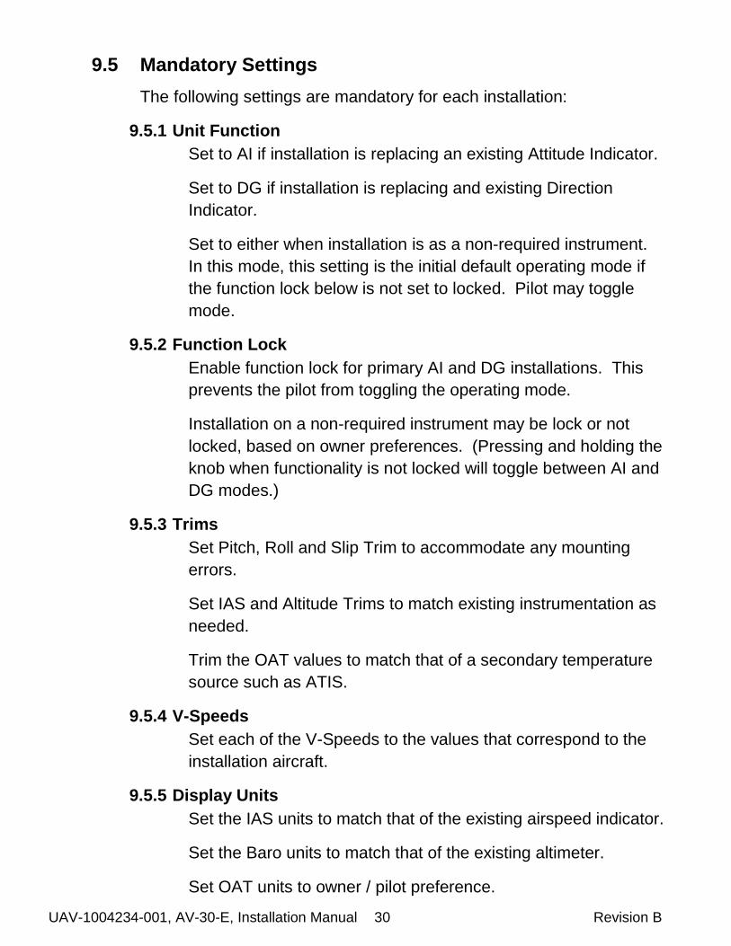
9.5 Mandatory Settings
The following settings are mandatory for each installation:
9.5.1 Unit Function
Set to AI if installation is replacing an existing Attitude Indicator.
Set to DG if installation is replacing and existing Direction
Indicator.
Set to either when installation is as a non-required instrument.
In this mode, this setting is the initial default operating mode if
the function lock below is not set to locked. Pilot may toggle
mode.
9.5.2 Function Lock
Enable function lock for primary AI and DG installations. This
prevents the pilot from toggling the operating mode.
Installation on a non-required instrument may be lock or not
locked, based on owner preferences. (Pressing and holding the
knob when functionality is not locked will toggle between AI and
DG modes.)
9.5.3 Trims
Set Pitch, Roll and Slip Trim to accommodate any mounting
errors.
Set IAS and Altitude Trims to match existing instrumentation as
needed.
Trim the OAT values to match that of a secondary temperature
source such as ATIS.
9.5.4 V-Speeds
Set each of the V-Speeds to the values that correspond to the
installation aircraft.
9.5.5 Display Units
Set the IAS units to match that of the existing airspeed indicator.
Set the Baro units to match that of the existing altimeter.
Set OAT units to owner / pilot preference.

UAV-1004234-001, AV-30-E, Installation Manual 31 Revision B
9.5.6 Serial Inputs
Set GPS Nav Source to the corresponding GPS navigator input
type. Most handhelds are NMEA outputs while most panel
mounted navigators are Aviation format. A tailBeaconX can also
supply GPS input by selecting BEACON X. If no GPS is
connected, set to NONE.
If connected to an Autopilot system using the APA Mini adapter,
Set Serial 2 to APA Mini, if using the AV-30-E as a control head
for a tailBeaconX Set Serial 2 to BeaconX, otherwise select
NONE.
9.5.7 Demo Mode
Set Demo Mode to DISABLED
9.6 System Checkout
9.6.1 Alignment
During initial startup, the ALIGN flag should be presented and
flash. This indicates internal sensor stabilization is occurring.
This should extinguish within 3 minutes, at which point valid
attitude or direction indication is displayed.
Figure 18 - Align Flag
If this is not observed, reference the trouble shooting section of
this document for additional information.

UAV-1004234-001, AV-30-E, Installation Manual 32 Revision B
9.6.2 Hard Calibration
If running SOFTWARE VERSION 1.1.0 or later the hard
calibration page will be accessible in the “SETUP” page by
pressing the left button. The aircraft MUST be on the ground
with no movement to perform Hard Calibration.
Rotate the center knob until “HARD CAL PRESS TO CAL” is displayed.
Press the center knob

UAV-1004234-001, AV-30-E, Installation Manual 33 Revision B
Make sure the aircraft is completely still, with no motion present. Do not leave the aircraft during the countdown.
Press the right button below “CALIB”
“Calibration in progress” will be displayed with a % complete.

UAV-1004234-001, AV-30-E, Installation Manual 34 Revision B
AV-30 will indicate “Calibration successfully completed Press DONE” Press the left button under “DONE” and the calibration is complete. If an error is shown, repeat the calibration process. Hard Calibration should only be performed annually or when directed by uAvionix.
9.6.3 OAT Interface
If an OAT probe is connected, utilize the display customization
guidance provided in the Pilots Guide to configure the display to
show OAT in at least one textual display field.
Figure 19 – OAT Indication
Note that OAT calibration is performed in the Setup procedures.
This step only ensures that the OAT probe is detected properly.
9.6.4 GPS Navigator Interface
If a GPS Navigator is connected, utilize the display
customization guidance provided in the Pilots Guide to configure

UAV-1004234-001, AV-30-E, Installation Manual 35 Revision B
the display to show GPS navigational data in at least one textual
display field.
The image below shows a typical configuration that the pilot may
setup.
Figure 20 – OAT Indication
On the GPS navigator, set a destination waypoint and initiate a
direct-to sequence. Note that not all navigators will output serial
data until a waypoint has been selected and navigation initiated.
9.6.5 tailBeaconX control Interface
Figure 21 - tailBeaconX Control
To Change Squawk
Press in the center knob
Navigate highlighted cursor to desired digit by rotating the knob
A Configured Callsign
B Current Squawk Code
C Mode Selection (STBY, ON, ALT)
D GPS NIC
E GPS NACp
F Pressure Altitude, Yellow indicates radar interrogation, Will change to IDT if IDENT is active
G Communication status (OK, TMOUT)
B C
E
G
A
F
D
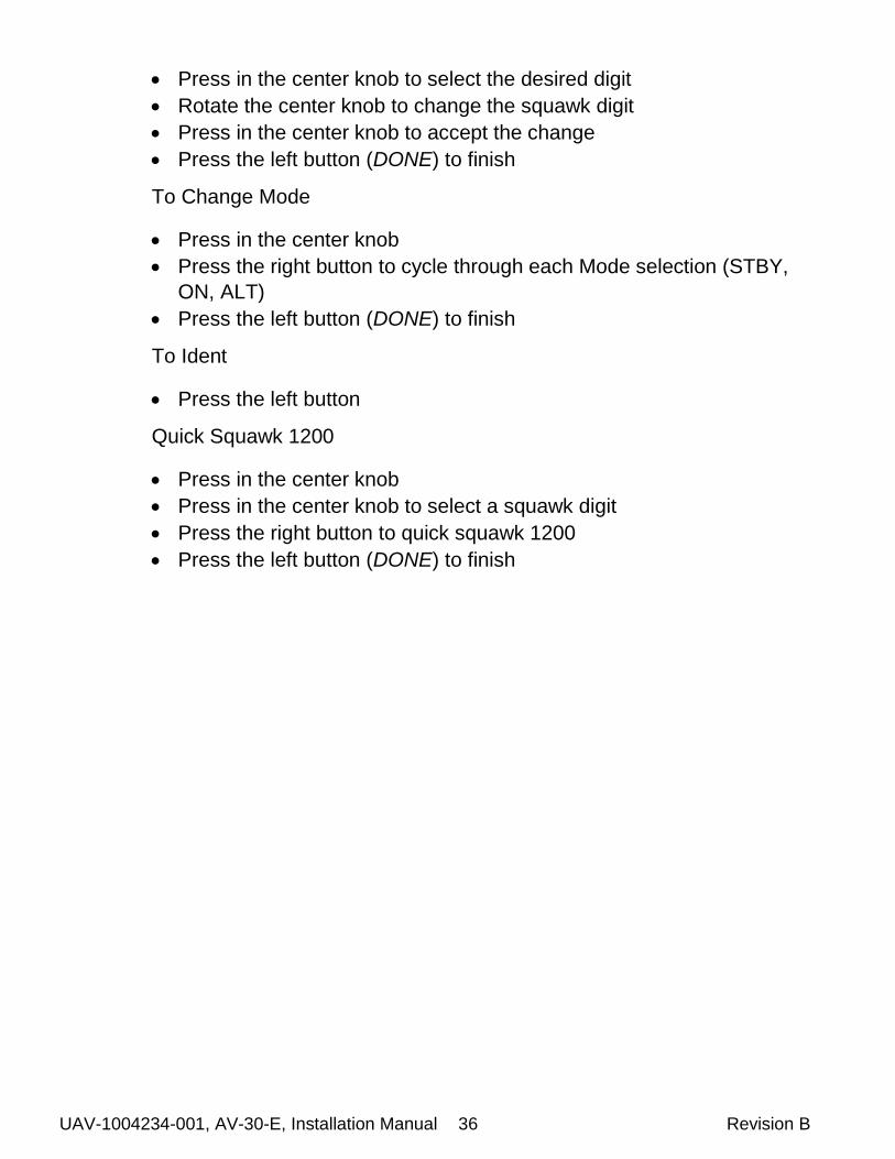
UAV-1004234-001, AV-30-E, Installation Manual 36 Revision B
Press in the center knob to select the desired digit
Rotate the center knob to change the squawk digit
Press in the center knob to accept the change
Press the left button (DONE) to finish
To Change Mode
Press in the center knob
Press the right button to cycle through each Mode selection (STBY,
ON, ALT)
Press the left button (DONE) to finish
To Ident
Press the left button
Quick Squawk 1200
Press in the center knob
Press in the center knob to select a squawk digit
Press the right button to quick squawk 1200
Press the left button (DONE) to finish

UAV-1004234-001, AV-30-E, Installation Manual 37 Revision B
10 Troubleshooting
The following steps are to aid in identifying installation or unit
performance related issues:
Issue Possible Resolution
Power Related Issues
Unit does not power-on Check associated breakers.
Ensure aircraft battery is greater than 10VDC.
Check wiring and pinouts.
Unit will not shut-off, even if power is removed
Ensure no pitot static blockage or line kinks are present (locking pressure and airspeed indication over 40 KTS).
Stabilization Related Issues
Unit will not stabilize and aligning flag remains on
Return to factory for service if unit does not align within 3 minutes of power-on.
DG drifts more than 30 degrees an hour
Make sure you are running the newest software.
Ensure that pilot only makes adjustments at most every 15 minutes
Battery Related Issues
Battery indication shows fail Contact factory.
Trim Related Issues
Roll, Pitch or Slip show small but constant error
Set associated trim adjustment in Installation Menus.
Airspeed or Altitude shows small but constant error
Set associated trim adjustment in Installation Menus.
Interface Related Issues
GPS information is expected but does not show up in data overlays.
Check GPS input is configured to match the connected GPS serial data type and speed.
Set a direction indication to GPS TRK. If “No Data” is shown, check interface cables and pinouts. If “No GPS” is shown ensure protocols and speeds are set correctly.
Alerts
Audio alerts are not being heard over the audio system
Check wiring and ensure alerts are enabled in the pilots Setup Menu.
Ensure un-switched input is available on the audio panel.
Verify volume setting is sufficiently high in the pilots Setup Menus.
Nuisance alerts are being generated Ensure alerting limits are configured as desired in the Setup Menus.
Disable any un-desired alerting features in the Setup Menus.
Table 8 – Trouble Shooting

UAV-1004234-001, AV-30-E, Installation Manual 38 Revision B
11 Serial Interface Specification
GPS serial input is compatible with the “Aviation” and NMEA serial
protocols. Aviation protocol is 9600 Baud, No Parity, 8 Data Bits, 1 Stop
bit. NMEA is either 4800 or 9600 Baud, No Parity, 8 Data Bits, 1 Stop
Bit.
The packets received are as follows:
Parameter Name Aviation Packet NMEA Packet
GPS Track “C” Packet $GPRMC, Field 8
GPS Ground Speed “D” Packet $GPRMC, Field 7
Distance to Waypoint “E” Packet $GPRMB, Field 10
Cross Track Error “G” Packet $GPRMB, Field 2
Desired Track “I” Packet Computed
Waypoint ID “K” Packet $GPRMB, Field 5
Bearing to Waypoint “L” Packet $GPRMB, Field 11
Magnetic Variation “Q” Packet $GPRMC, Field 10
AT Master Flag “T” Packet, Flag 4 $GPGGA, Field 6
Garmin Master Flag “S” Packet, Flag 5 N/A
Table 9 - GPS Serial Specification

UAV-1004234-001, AV-30-E, Installation Manual 39 Revision B
12 Field Update Capability
The unit software is field updateable and requires an in-line harness and
Windows based PC. Contact the factory for additional information.
1-AMP BREAKER
S
P
AIRCRAFT POWER
AV-20
NOTES:
ADAPTER HARNESS ALLOWS UNIT TO BE POWERED BY AIRCRAFT BUS
AV-30 DOES NOT NEED TO BE REMOVED FROM PANEL2
1
AV-30
PWR1
GND9
SER OUT15
15 PIN DSUB
FEMALE
PWR
GND
PWR
GND
EXISTING AIRCRAFT
WIRING
15 PIN DSUB
MALE
SER OUT
SER IN
9 PIN DSUB
FEMALE
2
SER IN 8
3
GND5
ADAPTER HARNESS(~5 TO ~12 INCHES LONG)
1
USB TO RS-
232 SERIAL
CONVERTER
USB
WINDOWS PC /
LAPTOP
2
Figure 22 - Field Update Harness