av controlstereoreceiver sa-ax730 sa-ax530 · sa-ax730 and sa-ax530, however, ere intended...
TRANSCRIPT
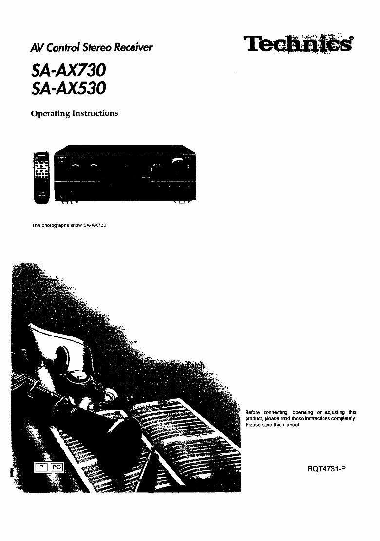
AV ControlStereoReceiver
SA-AX730SA-AX530
Operating Instructions
iThe photographs show SA-AX730
Before connecting, operating or adjusting thisproduct, please read these instructionscompletelyPlease save this manual
RQT4731 -P
Dear CustomerThank you for purchasing this product.For optimum performance and safety, please read theseinstructionscarefully.
Tableof contents
Precautions ........................................................................ 3Supplied accessories ....................................................... 4Concerning the remote control ........................................ 4Surround guide ................................................................. 5Front panel controls ......................................................... 6Equipment connections ................................................... 8Antenna connections ...................................................... 12Speaker connections ...................................................... 14
Basic operations ............................................................. 16Listening to radio broadcasts ........................................ 18
Sequential tuning ........................................................................ 18Direct tuning ............................................................................... 19Preset tuning .............................................................................. 20
Dolby Pro Logic ............................................................... 22
Setting the center mode and adjustingspeaker output level ...... 22Adjustingthe delay time ............................................................. 24EnjoyingSURROUND or 3 STEREO ......................................... 25
SFC (Sound Field Control) ............................................. 26Adjustingfield of sound .............................................................. 27
DMD 6CH INPUT mode .................................................... 28
Other functions ............................................................... 29To adjust the tone quality ............................................................ 29TOadjust the sound balance ....................................................... 29To mute the sound level ............................................................. 29To listen throughheadphones .................................................... 29
Making a recording ......................................................... 30Recording on a tape deck .......................................................... 30Recording on a VCR ................................................................... 30
Using the remote control ................................................ 31To operate the receiver ............................................................... 31To operate a cassette deck ...................................................... ._ja_., ,,TO operate a CD changer or CD player .................................... :_33'
To watch TV broadcasts ...................................................... _._13_ _, :"TO watch video t_.-:_;_ ............................... : ......... 3_ .To operate a DVD player ................................................. _,._ _36 _
Changing the rer_bte control code ._.:'37- _ '
_2qq.qll......... ;About the HELP function .......................................... _._ 38Listen ng caut oJ[1.,, .... _._..L;:.*.._8 _ _:
Maintenance ................................................................ _;_38 _- :;
Product Service';; ........................................................... 31_ _ .Troubleshooting guide ..:........_ ........... _ 3_: '' :
Technical specifications .................................. Back cover
CAUTION
Do not place a tape deck, CD, or DVD player on top of this unitHeat radiated from the top of this unit may cause damage tothe software.
NO
These operating instructions are applicable to models /SA-AX730 and SA-AX530, however, ere intended primarily Jfor model SA-AX730.
User memo:
DATE OF PURCHASEDEALER NAMEDEALER ADDRESS
TELEPHONENUMBER
The model number and serial number of this product can befound o_ either the back or the bottom of the unit.
Please note them in the space provided below and keep forfuture reference.MODEL NUMBER -SERIAL NUMBER
--THE FOLLOWING APPLIES ONLY IN THE U.S.A._/
CAUTION: |Any unauthorized changes or modifications to this Iequipment would void the user's authority to operate this I
device. /
WARNING:TO REDUCE THE RISK OF FIRE, ELECTRICSHOCK OR PRODUCT DAMAGE, DO NOTEXPOSE THIS APPLIANCE TO RAIN,SPLASHING, DRIPPING OR MOISTURE,
CAUTION:TO PREVENT ELECTRIC SHOCK MATCH WIDEBLADE OF PLUG TO WIDE SLOT, FULLYINSERT,
CAUTION
CAUTION: TO REDUCE THE RISK OF ELECTRICSHOCK, DO NOT REMOVE SCREWS.NO USER-SERVICEABLE PARTSINSIDE.REFER SERVICING TO QUALIFIEDSERVICE PERSONNEL.
_L The lightning flash with arrowhead symbol, withinan equilateral triangle, is intendedto alert the user
to the presence of uninsulated"dangerousvoltage"within the product's enclosure that may be of suffi-cient magnitudeto constitutea riskof electdcshockto persons.
_IL The exclamation point withinan equilateral tdangle
is intended to alert the user to the presence ofimportant operating and maintenance (servicing)instructions in the literature accompanying the ap-
.pliance.
RQT4731

I Precautions
Before using this unit please read these operating instructionscarefully. Take special care to follow the warnings indicated on theunit itself as well as the safety suggestions listed below.Afterwards keep them handy for future reference,
1. Power Source--The unit should be connected to powersupply only of the type described in the operating instructionsor as marked on the unit.
2, Polarization--if the unit is equipped with a polarized ACpower plug (a plug having one blade wider than the other), thatplug will fit into the AC outlet only one way. This is a safetyfeature. If you are unable to insed the plug fully into the outlet,try reversing the plug. If the plug should still fail to fit, contactyour electrician to replace your obsolete ouitet. Do not defeatthe safety purpose of the polarized plug.
3. Power Cord Protection--AC power supply cords should berouted so that they are not likely to be walked on or pinched byitems placed upon or against them. Never take hold of the plugor cord if your hand is wet, and always grasp the plug bodywhen connecting or disconnecting it
4. Nonuse Periods--When the unit is not used, turn the poweroff. When left unused for a long period of time, the unit shouldbe unplugged from the household AC outlet.
I Environment ]
1. Outdoor Antenna Grounding--If an outside antenna isconnected to the receiver, be sure the antenna system isgrounded so as to provide some protection against voltagesurges and built-up static charges. Section 810 of the NationalElectrical Code, ANSI/NFPA No. 70-1990, providesinformation with respect to proper grounding of the mast andsupporting structure, grounding of the lead-in wire to anantenna discharge unit, size of grounding conductors, locationof antenna-discharge unit, connection to grounding electrodes,and requirements for the grounding electrode. See figurebelow.
ANTENNALEAD tN
GROUND WIRE
DISCHARGE UNIT
(NEC SECTION 810-20 I
OUNDtNG CONDUCTORS
(NEGSECTIONe_o-21)_"'_- _ GROUND CLAMPS
POWER SERVICS GROUNDINGELECTRODE SYSTEM
(NEC ART 250, PART H)
NEC--NATIONAL ELECTRICAL CODE
1. VentilaUon--Tbe unit should be situated so that its location orposition does not interfere with its proper ventilation, Allow10 cm (4") clearance from the rear of the unit.
2. Foreign Material--Care should be taken so that objects donot fall into and liquids are not spilled into the unit. Do notsubject this unit to excessive smoke, dust, mechanicalvibratio_ or shock.
3, Magnetism--The unit should be situated away fromequipment or devices that generate strong magnetic fields.
4. Stacking--Do not I_lace heavy objects, other than systemcomponents, on top of the unit.
5. Surface--Place the unit on a flat, level surface.6. Carts and St;_nds--The unit should be used only with a cart or
stand that is recommended by themanufacturer. The unit and cad combination q9should be moved with care. Quick stops,excessive force, and uneven surfaces maycause the unit and cad COmbination tooverturn.
7. Wall or Ceiling Mounting--The unit should not be mounted toa wall or ceiling, unless specified in this operating instructions.
Clean the cabinet, panel and controls with a soft cloth lightlymoistened with mild detergent solution.Do not use any type of abrasive pad, scouring powder or solventsuch as alcohol or benzine.
1. Damage Requiring Service--The unit should be serviced byqualified service personnel when:(a) The AC power supply cord or the plug has been damaged;
or(b) Objects have fallen or liquid has been spitled into the unit;
or(c) The unit has been exposed to rain;or(d) The unit does not appear to operate normally or exhibits a
marked change in performance; or(e) The unit has been dropped, or the enclosure damaged.
2. Servicing--The user should not attempt to service the unitbeyond that described in the operating instructions All otherservicing should be referred to an authorized servicepersonnel.For the address of an authorized servicenter:In the U.S.A. 1-800-211.7262 or web site(http://www.panasonic.com)In Canada 905-624-5505 or web site
(www.panasonic.ca/fdbckca.htm)
=!i
2, Water and Moisture--Do not use this unit near water--forexample, near a bathtub, washbowl, swimming pool, or thelike.
Damp basements should also be avoided,3. Heat--The unit should be situated away from heat sources
such as radiators and the like.It also should not be placed in temperatures less than 5"C(41'F) or greater than 35=C (95"F). RQT4731
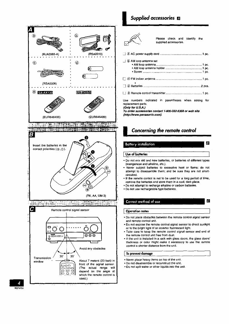
(RJA0065-A) (RSA0Ol0)• * * • • ° • • • ° o • ° .°° • ° • • • * • • • • • • ° •
©
(RSA0006)
(EUR646496) (EUR646489)
I Suppliedaccessories[]
Please check and identify thesupplied accessories.
[] _ AC power supply cord ..................................................... 1 pc.
[] _ AM loop antenna set• AM loop antenna .......................................................... 1 pc.• AM loop antenna holder .............................................. 1 pc.• Screw ........................................................................... t pc.
[] _ FM indoor antenna .......................................................... 1 pc.
[_ (_ Batteries ........................................................................ 2 pcs.
_ Remote control transmitter .............................................. 1 pc.
Use numbers indicated in parentheses when asking forreplacement parts.(Only for U.S.A.)To order accessories contact 1-800-332-5368 or web site(http://www.panasonic.com).
Insert the batteries in thecorrect polarities (®,®).
Transmissionwindow
(R6, AA, UM-3)
Avoid any obstacles
About 7 meters (23 feet) infront of the signal sensor.(The actual range willdepend on the angle atwhich the remote control is
used.)
I Concerningthe remote control
'.." H • []
[U,,of ,ter , I• Do not mix old and new batteries, or batteries of different types
(manganese and alkaline, etc.).• Never subject batteries to excessive heat or flame; do not
attempt to disassemble them; and be sure they are not short-circuited.
• If the remote control is not to be used for a long period of time,remove the batteries and stere them in a cool, dark place.
• Do not attempt to recharge alkaline or carbon batteries.• Do not use rechargeable type batteries.
, - - ,,, . []
I Operation notes I
• Do not place obstacles between the remote control signal sensorand remote control unit.
• Do not expose the remote control signal sensor to direct sunlightor to the bright light of an invertor fluorescent light.
• Take care to keep the remote control signal sensor and end ofthe remote control unit free from dust.
• If the unit is installed in a rack with glass doors, the glass doors'thickness or color might make it necessor_ to use the remotecontrol a shorterdistance from the unit•
I To prevent damage
• Never place heavy items on top of the unit.• Do not disassemble or reconstruct the unit.• Do not spill water or other liquids into the unit.
RQT4731

I Surroundguide
You are able to enjoy these two surround systems with this receiver.
Dolby Pro Logic is a decoding system that wasdeveloped to get a better sense of presence fromsources encoded with Dolby Surround. Thefeeling of position has been improved by theaddition of a separate center speaker channel.Dolby Surround was developed to allowenjoyment of Dolby Stereo, a cinema system, inprivate homes. This system reproduces soundclose to that of the original movie through u4seofan analog matrix.
This unit has two types of Dolby Pro Logic.• SURROUND: the surround speakers are
used.• 3 STEREO: the surround speakers are not
used.
_, (=).Page 22.)
SFC allows you to add surround-like effects tosources not formatted with Dolby Surround, DolbyDigital, or DTS.Various effects, like a concert hall or jazz club,can be achieved by introducing width orreverberation to the original sound.(=$,Page 25.)
• Video tapes• Laser discs•DVDs• CDs
Software encoded with DolbySurround can be identified with this
mark.
OO[°°L"Y'u""°u"°l
Any kind, but particularly music CDsand video tapes.
Dolby Digital(AC-3)
Dolby Digital is a discrete 6 (5.1) channel digitalsurround system developed for cinema use.The sound signals in Dolby Digital format arecompressed to 1/10 their original size, allowing anentire movie to be recorded on a single UVD.Not all Dolby Digital sources are recorded with 6channels. Some sources marked Dolby Digitalmay be recorded in Dolby Surround, a 2 channelsystem.(=kPage 28,)
DTS
DTS is a discrete 6 (5.1) channel digital surroundsystem developed for cinema use. Sourcesencoded in DTS are only compressed to a quarterof the size of the original to preserve soundquality.DTS sources are produced with the intention thatall speaker channels will be used.(_Page 25.)
,DVDs
Both the playback equipment andsoftware must have this mark.
DDr- - flDIGITAL
• J
• DVDs• Laser discs• COs
Both the playback equipment andsoftware must have this mark.
DIGITAL
SURROUND
RQT4_I

I Frontpanel controls
I Main unit I
No. Name Ref.page
(D Power "6/i" switch(POWER, L_/i)...................................................... 16
Press to switch the unit from on to standby mode or vice versa,in standby mode, the unit is still consuming a small amount ofpower.
(_)Sound mode selector/indicators ...................... 22® SFC mode selector (MODE) .............................. 26_) Input indicators .................................................. 16® DVD 6ch input select button/indicator
(DVD 6CH iNPUT) ............................................... 28® input selector (INPUT SELECTOR) .................. 16(_ Volume control (VOLUME) ................................ 16
Speaker select buttons (SPEAKERS A, B) ...... 16
Speaker button (SPEAKERS) ............................ 16
No. Name Ref.page® Help/reset button (-HELP -RESET) .................. 38(_ Headphones Jack(PHONES) ............................. 29_) Display(_Tape monitor button (TAPE MONITOR) ........... 17
Bass control (BASS) .......................................... 29@Treble control (TREBLE) ................................... 29(_ Balance control (BALANCE) ............................. 29
Delay time adjust button (DELAY TIME) .......... 24Center mode select button(CENTER MODE) ................................................ 22
_Tuning buttons (TUNING V,A) ......................... 18Radio station presetting button (PRESET) ...... 21Band select button (BAND) ............................... 18
_) FM mode select button (FM MODE) ................. 18Memory button (MEMORY) ............................... 20
RQT4731

I Front panel controls
I Remoteconlrol
No. Name Ref.page
O Power button ( 6 ) .............................................. 31(_) • button ( • ) ...................................................... 32(_) _</_4 button (_</,i_) ..................................... 32_) • button ( • ) ...................................................... 32_)Title button (TITLE) ............................................ 36® Display button (DISPLAY) ................................. 36<_)Dolby Pro Logic surround select button
(SURROUND) ...................................................... 31_)Doiby Pro Logic/SFC off button (STEREO) ..... 31_)Speaker channel select button (LEVEL) .......... 31_Delay time button (DELAY) ................................ 31_)Channel upldown buttons (vCH,') .................. 32_Muting button (MUTING) ................................... 31_Input select buttons
(TV, VCR, TAPE, CD, TUNER/BAND, DVD) ....... 31• •/l_,_ button (_-•/_-_) ...................................... 32
_Curaor/select buttons ........................................ 36_Menu button (MENU) ......................................... 36_)SEC mode select button (SFC) ......................... 31_Test button (TEST) ....................................... 23, 31_Delay time/level adjust buttons (-, +) ......... 23, 31_Direct tuning/disc enter button
(DIRECT TUNING/DISC ENTER) .................. 19, 32_) __';Td!_*f-,V-.V._Z<T=]
>10/enter button (>lo/ENTER) ........................... 32
>10 button (_>10).................................................. 32@Numeric buttons .......................................... 19, 32_Disc/deck 1/2 select button (DISC/DECK 1/2).. 32_TVIvideo select button (W/VIDEO) .................. 34_Volume buttons (-VOL+) ............................. 23, 31
ROT4731

I Equipmentconnections(SA-AX730)
Stereo connection cable (not Included)
White (L) _ (,aa=_=Red (R)
Video connection cable (not included)
Make sure that the power supply for all components has beenturned off before making any connections.
To connect equipment, refer to the appropriate operatinginstructions.
Do not place books, etc., on the top of this unit or block theheat radiation vents in any way.
notlecluded)
PLAY (OUT) REC (IN)
CD changer (or CD player) TV(not included)(not Included)
UTPUT AtOUT
"SWITCHED" AC outletPower to the outlet is controlledby the power switch of this unit.Audio equipment rated up toTOTAL 80 W can be connectedhere.
Only forturntable with
groundterminal.
\
GN[ OUTPU3"
J I
Turntable (not included)
AUDIOl
OUT |
i:AUDI( VIDE VIDEO
iN OUT _N
C:3
VCR (not included)
Cooling fanThe cooling fan operates athigh power output levelsonly.
AC power supply cord(included)
oCn/;neaC_ert_:,/ o_hredl
cCoabnlneeStaeddcords are] Household AC outlet(AC 120 V/60 Hz)
ROT,_I

Monauralconnectioncable(notIncluded) Opticalfibercable(notincluded)
6channeldiscrete connection enables you to enjoy the sound field effects recorded on DVDs.
............. ...... ,OO
gg
AUDIO OUT
(CENTER)
DVD player(not included)
I
AUDIO OUT VIDEO _,UDID OUT(SURROUND OUT [FRONT LR)
If your DVD player doesn't have surround decodersObtain a separately available digital surround processor.
AUDIO OUT
(SUBWOOFER)
Digital surroundprocessor
AUDIOOUT (not included)(FRONT L,R)
DIGITAL
pN
DVD player(not
VIDEO OUT
DIGITAL
OUT
Stereo connection
Usethis connectionif none of your equipment has asurround decoder.
i
AUDIO OUT
(MIXED AUDIO OUT)
VIDEOOUT
00
ooo
DVD player(not included)
RQT4_I

I Equipmentconnections(SA-AX530)
Stereo connection cable (not included)White (L)Red (R)_I_=m. ]
Video connection cable (not included)
Make sure that the power supply for all components has beenturned off before making any connections,
To connect equipment, refer to the appropriate operatinginstructions.
Do not place books, etc., on the top of this unit or block theheat radiationvents in any way.
Tape deck (not included)
PLAY (OUT) REC (IN)
CD changer (or CD player)(not included)
--OUTPUT_
TV (not included)
"SWITCHED" AC outletPower to the outlet is controlledby the power switch of this unit.Audio equipment rated up toTOTAL 80 W can be connectedhere.
Only forturntable withgroundterminal.
GND OUTPUT
__
Turntable (not included)
OUT /_N / OUT IN
H: °VCR (not included)
Cooling fanThe cooling fan operates athigh power output levelsonly.
AC power supply cord(included)
Connect this cordonly after all other
connected. _]cables and cords are
Household AC outlet(AC 120 V/60 Hz)
I_T4731

Monaural connection cable (not Included) Optical fiber cable (not included)
_Lltd
6 channel discrete connection enables you to enjoy the sound field effects recorded on DVDs,
AUDIO OUT(FRONT L R)
DVD player
(not included)
AUDIOOUT(SUBWOOFER}
If your DVD player doesn't have surround decodersObtain a separately available digital surround processor.
Digital surroundprocessorAUDIOOUT
(SUBWOOFER)(not included)AUDIO OUT
VIDEOOUT
J
DIGITALIN
IDIGITAL
VIDEO OUT OUT
DVD player _o° _(notincluded)
Stereo connectionUse this connection if none of your equipment has asurround decoder.
AUDIO OUT
DVD player(notincluded)
0 @
RQT4731

-_ FM indoor antenna
(notineluded)
/
AM toopantenna(included)
/
AM ANT [_
AMLOOPANT
i Antenna connecllons
This antenna {s norma{{y sufficient for reception ot FM broadcasts.
Attach to a wall (using tape) facing in the direction of bestreception.
For best receptlenAn FM outdoor antenna is recommended,
• _ o'e []
This antenna is normally sufficient for reception of AM broadcasts.
Fit the AM loop antenna holder (included) onto the rear panel ofthis unit and then attach the AM _c_p antenna to the AM loopantenna holder (facing in the direction of best reception).
Pay attention to the following points when mounting theantenna.• Do not mount it close to power cords, speaker wires or metal
surfaces (Doing so will result in noise).• Do not mount it close to a tape deck. When the tape deck is
being used, chirping or beeping sounds may result.
[ When mountingIhe antenna to a column,a wall or rackr;i[
Mount the antenna so that the hinge is vertical.
Screw (included)
RQT4731

u
rd
FM outdoor antenna
s(not included
75 Q coaxial cable
not included)
Remove a piece of theouter vinyl insulator.
20 mm (25132")@ Twist the shield braid to
expose the core wire.Core wire
Shield braid _
t Omm {3/8")
_) Connect the shield braid and th(core wire as shown at left.
Vinyl-covered wire(not included)
AM loop antenna(included)
AM AI _ ".
AM LOOP ANT
I Antennaconnections
• _ H m.o []
An outdoor antenna should be used when using this unit inmountainous areas or in spaces enclosed by reinforced concretewhere the FM indoor antenna (included) does not providesatisfactory reception.Disconnect the FM indoor antenna if an FM outdoor antenna isinstalled.
An outdoor antenna should be installed by a qualified technicianonly.
An outdoor antenna should be used when using this unit inmountainous areas or in spaces enclosed by reinforced concretewhere the AM loop antenna (included) does not providesatisfactory reception.
Stretch 5-12 m (16-40 ft.) of vinyl-covered wire horizontallyacross a window frame or other convenient location, keeping it ashigh as possible from the ground.
When the unit is not in use, disconnect the outdoor antenna toprevent possible damage that may be caused by lightning. Neveruse an outdoor antenna during an electrical storm.
Be sure to connect the AM loop antenna even when an outdoorantenna is used.
ROT4731

I Speaker connections
Front speaker Center speaker Front speaker(Left) (not=included) (Right)(not included) _ (not included)
Subwoofer(not included)
Surround speaker _,/2" Surround speaker
(Left) _ (Right)(not included) (not included)
Front speakers
Place the front speakers on the left and right of the TV at seated
ear height so there is good coherency between the picture andsound.
Center speakerPlace this speaker underneath or above the center of the TV. Aimthe speaker at the seating area.
Surround speakersPlace these speakers on the side of or slightlybehind the listener,and abo_t one meter higher than ear level.
SubwooferThe subwoofer can be placed in any position as long as it is at areasonable distance from the TV.Note that SO[he experimentation can yield the smoothest lowfrequency performance. Placement near a corner can increase theapparent output level, but can result in unnatural bass.
Other connections are possible depending on your speaker system.See your speaker system's operating instructions for details.
I Front speakers
This model has onl, one set of front speaker terminals.
Speaker impedance:
]_AorS: 4-8_
I A and B: 8
Front speaker(Right)(not included)
,/
O@O@
O@0_"0 @
@0@00@
.____ Speaker cable __(not included)
[
O - J
r
Connecting the cables
=:::: 2 *
4, o
"B" terminalsForconnectionto a secondpairof speakers.
Front speaker(Left)(notJnoluded)
\
r
J
Use the A terminals to enjoy Dolby Pro Logic, SFC, and DVD 6CHINPUT.
RQT4731

Other speakers ]
/
Surround speaker(Right) (not included)
Surround speaker(Leff)(notincluded)
(notincluded)f
Speaker cable(notincluded)
O@0 @ _,= --._........
o@ @© _
0 © © 0 _
O_ O@ © @©0© _v
oo©
\
SSubwoofer with built-in Speaker cablesamplifier (not included) (not included)f
INPUT
.................. .'".P.uz.
Speaker cable(not included)
Monaural-Stereo converter cable (not included)(Connect to the L or R terminal if a monaural cable is used.)
Power Amplifier(not included)
i i
Subwoofer without built*inamplifier (not included)
]For surround speakers For subwoofer
ur;_lDo not connect the surround speakers to the front speakerterminals. The surround speakers may be damaged if connectedto the front terminals.
Speaker impedance:
Centerspeaker: 8Surroundspeaker: 8
This receiver has no amplifier section designed especially for thesubwoofer.
For your referenceConnection to a passive subwoofer with front speaker terminals isalso possible. (See the operating instructions of the speakersystem for details.)
RQT4731

= Io c_3 o ci3_©
j@@@
SPEAKERS
%
INPUT SELECT_R_ _
Selected source
I Basic operations
Before operation, set VOLUME to the "MIN" position.
[] Press, [POWER].
ImlPress [A] and/or [B] to select the speaker
system(s) to be used.A and B refer to the speaker terminals at the rear of the unit.
Press [SPEAKERS] and check the"SPEAKERS" indication lights up.
if the button is pressed once more, the indicator will switchoff and no sound will be heard from the speakers.
_1 Turn [INPUT SELECTOR] to select and startthe desired source•(Referto theappropriateoperatinginstructionsfor details.)
The indicator which corresponds to the seleCted input sourcewill illuminate.The selected source will be shown on the display.
TAPE (MONITOR): To listen to cassette tapesVCR: To watch videotapesTV/DSS: To watch TV or DSSDVD: To watch DVDCD: To listen to compact discsTUNER: To listen to radio broadcasts
PHONO: To listen to phono discs
If a Dolby Pro Logic or SFC mode has beenselectedAfter displaying the selected source, the display will thenchange to show the Dolby Pro Logic or SFC mode,If the source chosen was TUNER then the display willchange again to show the frequency,
To watch a video (or DVD) or the "IV, set the TV to either theTV mode or VIDEO mode.
For your referenceIf you are using a VCR and you select TAPE, CD, TUNER,or PHONO, the picture will remain on the screen.
[] Adjust the volume.
• • • • * • • • • • • • • * • • • • * • • • • • ° • • • • •
When you finish listeningBe sure to reduce the volume level and switch the power to thestandby condition by pressing [POWER].
RQT4731

ASPEAKERSB
0 0
TAPE MONITOR
I Basicoperations
I When usingspeakersunder 8 Q _ [] I
Press and hold [A] or [B] until "LOW IMP" lightsup on the di_splay.
If even one of the speakers being used has an impedance under
8 _, press and hold down either button A or button B for 4
seconds or more to set the impedance to LOW.
]Pressandholddown onceagainfor4 secondsor moreto turnitoff.)
Note that when "LOW IMP" is iUuminated, speakers [] and []
cannot bothbe used at the same time.
TO change e speaker:
e.g. To use speaker [], press [A] ]m goes out), and then press
[B] to activate speaker [].
[ Tape monitor " [] J
If [TAPE MONITOR] is pressed while a source other than"TAPE (MONITOR)" is selected, the "TAPE (MONITOR)" indicatorlights and the tape monitor comes on.
Sources other than tape can still be selected with]INPUT SELECTOR] while the "TAPE (MONITOR)" indicator is on.
Press [TAPE MONITOR] again to turn the tape monitor off.
('_ See "Recording" on page 30 for details on how to use the tapemonitor during recording,)
ROT4731

Selected band
TUNING
I Listeningto radio broadcasts
Use the tuning buttons to tune-in radio stations.
_1 Turn [INPUT SELECTOR] to select "TUNER".
[] Press [BAND] to select "FM" or "AM".
• _1 Press FUNING ('X/) or (/k,)] to tune to thedesired frequency."QUARTZLOCK"lightsup whentuned,"S'I*EREO" lights up when an FM stereo broadcastisreceived.
To make an automatic search for stations
If [TUNING (V) or (^)] is held down for an instant until thelrequency begins to scro)i, the broadcast stations are tunedin automatically when one is found,
Tuning may stop automatically it any jamming isencountered.
• • • • • • • • • • • • • * • • • • = • • • • • • • • • • •
if noise is excessive in the FM stereo modePress [FM MODE].("STEREO" willgo out, and "MONO" will light up)
The broadcast wiltbe monaural but noise wilt be reduced.If the button is pressed once more, the stereo mode resumes.
For your referenceThe tuneT can pick _p interference from DVD players. I1 thisoccurs turn the DVD off.
RQT473t

I Listeningto radio broadcasts
TUNER/
Selected band
* • • • * • * • • • • • • • • * • • • * , • * • • • •
_l_rt_PJ
OIRECT11JNING_DISCEi_TER
%
88°
Specify the frequency using the numeric buttons on the remotecontrol to directly tune to the desired station.
[] Press [TUNER/BAND].This will set the remote control to operate the tuner.
The selector on the receiver will change to "TUNER".
Each time the button is pressed, the band will change as
follows,FM *_ AM,
[] Press [DIRECT TUNING/DISC ENTER].
] While cursordisplay isflashing(approx.10seconds)
Press the numeric buttons to enter the
frequency.
If the desired FM frequency is 107.9 MHz, press
If the frequency has been input correctly, the displayedfrequency will blinkonce.
1. If no button is pressed while the cursor display is flashing,the display will return to the frequency which is currentlybeing received. To re-specify the frequency, repeat theprocedure from step 2,
2. If the frequency has not been input correctly, "ERROR"will be displayed. In this case, re-enter the frequency.
ImRQT4731

I Listeningto radio broadcasts
Presetting radio stations into the memory channels of this unitmakes selecting stations simple,
A total of 30 FM and AM stations can be preset.
Please remember this
If a new broadcast station is preset into a channel, the setting forthe broadcast station which was previously entered in that channelwill be automatically erased.
Automatic memory presetting 1
Automatic memory presetting allows this unit to automaticallysearch for broadcast stations and then preset them into memory.With this method, the channels that can be preset into the memoryare set as follows for different bands (FM or AM).
When FM stations are preset,For FM stations......................................................................... 1-30
When FM and AM stations are preset,For FM stations......................................................................... 1-20For AM stations ...................................................................... 21-30
reSet to the frequency from which you want to
start automatic memory presetting.(=1,Page 18-19.)
[] Press [MEMORY] until the frequency beginsto change.[Automaticmemorypresettingwillstad.)Duringautomaticmemorypresetting,the memoryindicatorwillflash whilethe frequencyscrolls•
To stop, press [MEMORY] once again.
• • • • • • • • • • * • • • * • • • • • • • • • • • • • • •
When a broadcast station is preset []
The memory indicatorand the preset channel number will bedisplayed for approximately 1 second•
When presetting Is completedThe last broadcast station to be preset will be displayed,
Frequencies may not be preset correctly in cases where thebroadcast waves are too strong or too weak. In such cases, carryout presetting manually. (=_ Page 21 .)
RQT4731
I Listeningto radio broadcasts
I Manual memory presetting [] I
The desired stations can be preset into the desired channels bythe user.
IT set to the desired frequency.(,,_ Page1B-19.)
If interference or static is keeping you from enjoying an FMbroadCast, press [FM MODE] and change to monaural.You can preset the station in monaural lust as in stereo.
[] Press [MEMORY].To cancelthememoryfunction,press[MEMORY]again.
[] Press [TUNING (_/) or (/_ )] to select thedesired channel.Holdingthe buttonsdownlets youscrollthroughchannelsfaster.
[] Press [MEMORY].The channel will blink on the display.
To continue presettingRepeat steps 1 through 4.
I Tolistentopresetchannels[]
[] Press [PRESET].
[] Press [TUNING (V) or ( A)].HoLding _own the buffons Lets you scroL_ through chanr,,etsfaster.
The channel number will be changed for approximately5 seconds.Select the desired channel number during that time.
Atte_ 5 seconcls, the disb(_y wit{ ch_'_3e from the chanr_et ,_number to the frequency.
i_r_
If you press [PRESET] while the channel number is displayed, thedisplay will change to the frequency.
To confirm the channel number of the broadcast
station being receivedPress [PRESET].(The channel number will be displayed for approximately5 seconds.)
The channel number is not displayed if you change the frequencyor FM mode setting.
For your referenceEven if the power cord is disconnected from the household ACoutlet, the memory will retain its contents for approximately onemonth.
If frequency presettings are accidentally erasedProgram the presettings once again.The power cord should remain connected for one hour or more forthe memory back-up to be effective•
RQT4731
° ° ° ° ° ° ° O
mCENTERMODE
I Dolby Pro Logic
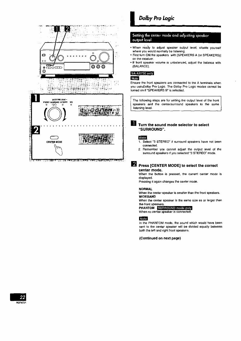
• When reacly to adjust speaker output level, situate yourselfwhere you would normally be listening.
• First turn ON the speakers with [SPEAKERS A (or SPEAKERS)[on the receiver•
• If front speaker volume is unbalanced, adjust the balance with[BALANCE].
Ensure the front speakers are connected to the A terminals whenyou use_olby Pro Logic• The Dolby Pro Logic modes cannot beturned on it "SPEAKERS B" is selected.
The following steps are for setting the output level of the frontspeakers and the center/surround speakers to the samelistening level.
_11 Turn the sound mode selector to select"SURROUND".
1. Select "3 STEREO" if surround speakers have not beenconnected.
2. Remember you cannot adjust the output level of thesurround speakers if you selected "3 STEREO" mode.
[] Press [CENTER MODE] to select the correct
center mode.When the button is pressed, the current center mode isdisplayed.Pressing it again changes the center mode.
NORMALWhen the center speaker is smaller than the front speakers.WIDEBAND
When the center speaker is the same size as or larger thanthe front speakers.PHANTOM I "o!_= ,,- , ,When no center speaker is connected.
In the PHANTOM mode, the sound which would have beensent to the center speaker will be divided equally betweenboth the left and dght front speakers.
(Continued on next page)
ROT4731

TEST
SURROUND modeL _C_ R_ St
3 STEREO modeL _C_ Rt__l
m
• • • • • • • • • ° • • • • • • • • • • • • • • • •
-- VOL+
• • • • ° • • • • • • • • • • • • • • • • • • • • •
LEVEL
Selected channel
I Dolby ProLogic
] _ e- • • • •
Press [TEST] to output a test signal.The speaker outputting the test signal is displayed while thetest is running.L : Front speaker (Left]C :Center speakerR : Front speaker (Right]S : Surround speakers
The subwoofer is muted while testing.
In the PHANTOM mode, the center speaker is OFF, so thereis no center test signal and "C" is not displayed.
] iL_,Vnl._ i I iol f_ll_o] 111ii] d
Press [VOL (-) or (+)1 to set the volume level
normally used for enjoying the source.
] _ • • • i v
Press [LEVEL] to select the center orsurround speakers•
] _ • • • • T
Press [-] or [+] to adjust the output level•Adjust the output level of each speaker from the listeningposition until they are all identical.
-: Decrease the output level.+: Increase the output level,Output level can be varied within a range of -12 dB to +12dB with front speaker output level serving as the zero point.
During steps 5 and 6 above the test signal sequence isinterrupted and the signal will only come from the selectedspeaker.Tbe sequence will resume when adjustments are stopped.
• • • • • • • • • • • • • • • • • • • • • • • • • • • • • •
TO stop the test signalPress [TEST].
To turn off the Dolby Pro Logic systemsPress [STEREO].
ROT4731

I Dolby ProLogic
CZ_DELAYTIME
Front speaker Front speaker(Left) Center speaker (Right)
Surround speaker Surround speaker(Left) (Right)
Iilililllill'.lillil,I liilli,J,niill,.lll il Ileli I I I illiil _i
Adjust the s()und from the surround speakers until the propereffect is produced.
Im Turn the sound mode selector to select"SURROUND".
IP_ Press [DELAY TIME] to set the time•When the button is pressed, the current delay time isdisplayed.Each time the button is pressed, the delay time will increaseby 5 ms within a range of 15 ms to 30 ms.
The standard setting is 20 ms.
i Tocalculate_nedelay llme [] I
D,: Distance from front speakersD=: Distance from surround speakers• If D_is equal to or less than D=
Set to 15 ms.• If D=is less than D,
Start at 15 ms and increase by5 ms for every 1.5 m of differencebetween D_and D_,
RQT4731

• • " • D • _:[_:[e)
I Oolby ProLogic
[] Turn [INPUT SELECTOR] to select and startthe desired source.
]Turn the sound mode selector to select
"SURROUND"or"3STEREO",
When employing SURROUND, use software recorded in_ .... Dotby Surround
• ................ ,............
For your'referenceYou can set the Dolby Pro Logic mode for each sourceEach source will retain the selected mode
INPUT SELECiRo _
• ° . , ° . ° • • ° ° • ° . ° ° ° ° ° ° ° , ° • ° ,
To turn off the Dolby Pro Logic systemsTurn the sound mode selector (_) to select "STEREO".
Manufactured under license from Dolby Laboratories LicensingCorporation.Dolby, the double-D symbol TIO and =PRO LOGIC" aretrademarks of Dolby Laboratories Licensing Corporation.
RQT4731

MODE
Selected SFC mode
i SFC(SoundField Conh'ol)
The SFC function gives presence and spread thereby enhancingand enriching the music or movie.Read the foflowing explanations in order to better understand howto make your.selection.
The center speaker is not used in the hall, and simulated modes.
HALL
This mode imparts e reflection and spread which will make youfeel as if you are in a large concert hall.
CLUBLike a jazz club, this mode provides an exciting and intimateatmosphere. It simulates the sound field of a relatively small roomhaving a low ceilingend hard reflective surfaces, for a "live"sound
with enhanced presen(:e to bring the performers up close.
LIVEPrimarily for vocal pieces, this mode adds gloss to the vocals andyou'll feel as though you were hearing a live stage performance.
THEATER
You can clearly perceive the directionsand source of the movie.Real ambience of sound can also be recreated naturally using thismode.THEATER mode can be used with stereo sources not encodedwith Dolby Surround.
When using Dolby Surround encoded materials, select"SURROUND".
SIMULATED (SIM SURR)Choose this mode if little or no sound will be heard from the
surround speakers.You can feel as if you were in a more expanded space adding tothe actual sound from the source.This mode also adds effect to monaural sources by outputtingsound from surround speakers.
[] Turn [INPUT SELECTOR] to select and startthe desired source.
_'_Turn the sound mode selector to select"SFC".
[] Turn [MODE] to select the desired SFC mode,
The SFC mode can also be selected by directly turning[MODE] instep 2 instead of selecting "SFC".
• • • • • • • • • • • ° • • = , • =• • • • • = , • • = • • •
For your referenceYou can set the SFC mode for each source.Each source willretain the selected mode,
To turn off the SFC functionTurnthesoundmodeselector(_) toselect"STEREO".
l.._b
RQT4731
Ensure the front speakers are connected to the A terminals whenyou use SFC.The SFC modes cannot be turned on if "SPEAKERS B" isselected,

*ITJ _ nT*l |=J[_(i] *|1_*]1[*] iII
LEVEL
Selected channel• • • . . • • • • * • . • • • • • = , • • ° ° • • .
%Output level
I SFC(SoundFieldControl)
With this unit, you can adjust speaker volume,Adjust the field of sound while listening to a source.
[ To adjust the volume of the center and surround speakers [] ]
_! Press [LEVEL] to select the center orsurround speakers.
You can adjust the center speaker volume only in the theatermode.
[] Press [+] or [-] to adjust the output level.
I ToadjustIhedelaytime [] ]
Press [DELAY TIME] to set the time.Whenthebuttonis pressed,thecurrentdelaytimeisdisplayed.Eachtimethebuttonispressed,thedelaytimewillchange.
The delay time increments are diffemnt depending on the SFCmode.Select a delay time setting to accommodate to your individualneeds•
SFC modes Available delay time setting (ms)HALL 20, 25, 30,40, 50CLUB 0,15, 20, 25, 30LIVE 15, 20, 30, 40, 50
THEATER 15, 20, 25, 30, 40SIMULATED 15, 20, 25, 30, 40
The figures in bold italics are the factory settings.
DELAYTIME
RQT4731
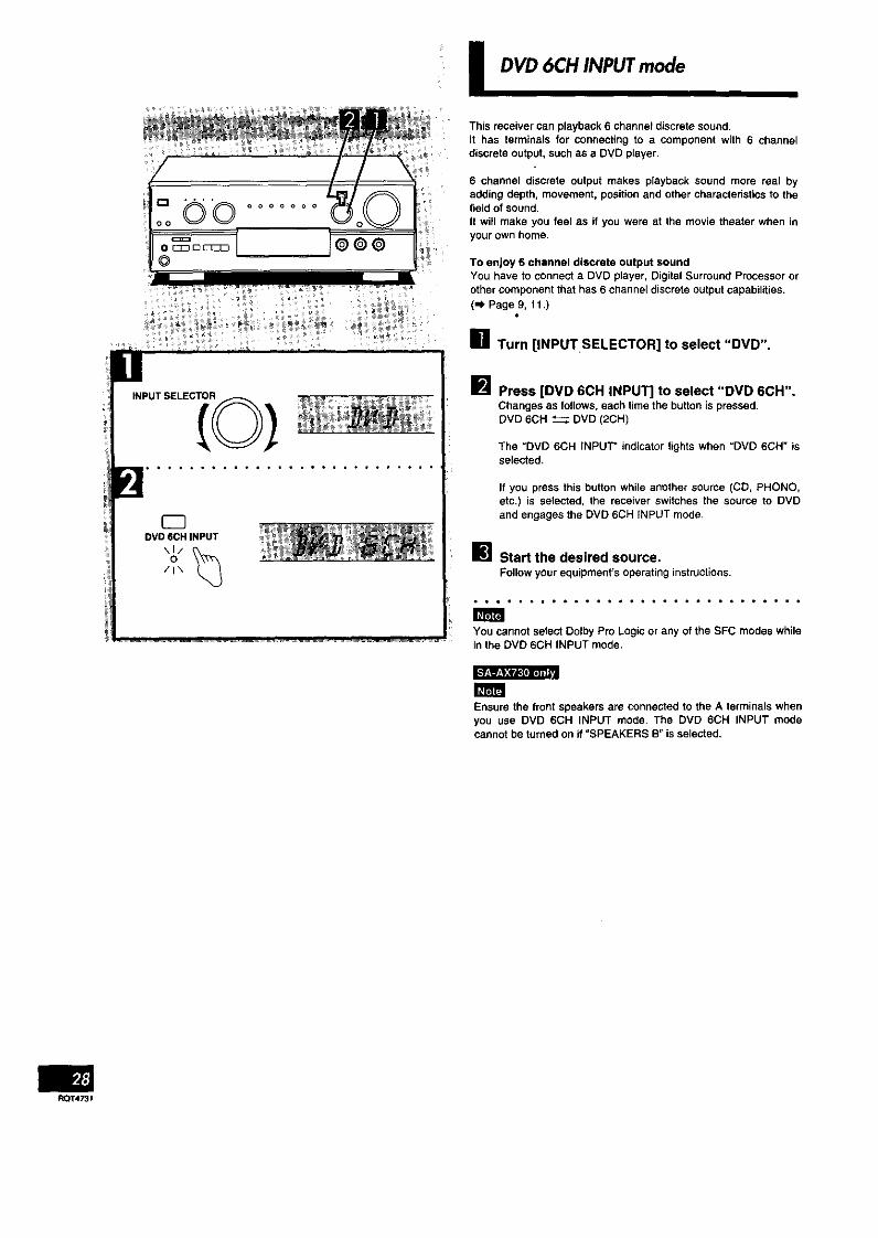
I DVD 6CH INPUTmode
F.©O o o o o o o o
o © © © :
INPUT SELEC[o )
• • • . • • • • • • • • • • * • • • • • • • * • • •
OVD 6CH INPUT
\1/0 _(_/l\
This receiver can playback 6 channel discrete sound.it has terminals for connecting to a component with 6 channeldiscrete output, such as a DVD player.
6 channel discrete output makes playback sound more real byadding depth, movement, positionand other characteristics to thefield of sound.It will make you feel as if you were at the movie theater when inyour own home.
To enjoy 6 channel discrete output soundYou have to connect a DVD player, Digital Surround Processor orother component that has 6 channel discrete output capabilities.(=_ Page 9, 11.)
[] Turn [INPUT.SELECTOR] to select "DVD".
IF_.RPress [DVD 6CH INPUT] to select "DVD 6CH".Changes as follows, each time the button is pressed,DVD 6CH _ DVD (2CH)
The "DVD 6CH INPUT" indicator lights when "DVD 6GH" isselected,
If you press this button while anether source (CD, PHONO,etc.) is selected, the receiver switches the source to DVDand engages the DVD 6CH INPUT mode.
_] Start the desired source.Follow yourequipment's operating instructions.
You cannot select Oolby Pro Logic or any of the SFC modes whilein the DVD 6CH INPUT mode,
Ensure the front speakers are connected to the A terminals whenyou use DVD 6CH INPUT mode. The DVD 6CH INPUT modecannot be turned on if "SPEAKERS B" is selected.
RQT4731
.l 4E J m
,L,L,L_ I_1
• BASS - TREBLE
• BALANCE
(@1] . • • • • • * • • • • * • • • • • • • • * • • • • • •
VOLUME
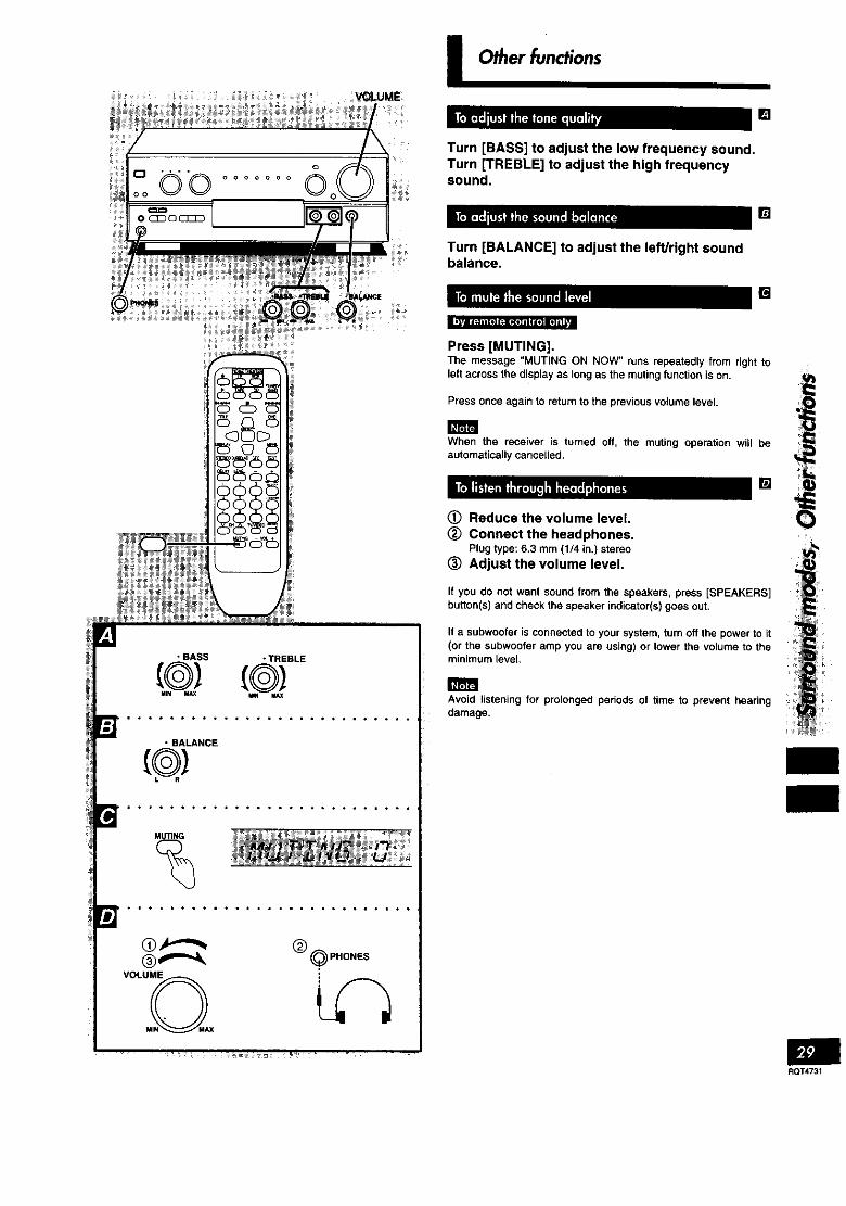
i Other functions
Turn [BASS] to adjust the low frequency sound•Turn [TREBLE] to adjust the high frequencysound•
Turn [BALANCE] to adjust the left/right soundbalance,
Press [MUTING],The message "MUTING ON NOW"runs repeatedlyfrom right toleft across thedisplayas longas the mutingfunction is on.
Press once again to return to the previous volume level.
When the receiver is turned off, the muting operation will beautomatically cancelled.
• - • • *eee • - []
(_ Reduce the volume level.
(_ Connect the headphones.Plugtype:6.3 mm (1/4 in,)stereo
(_ Adjust the volume level.
If you do not want sound from the speakers, press [SPEAKERS]button(s) and check the speaker indicator(s) goes out.
If a subwoofer is connected to your system, turn off the power to it(or the subwoofer amp you are using) or lower the Volume to theminimum level,
Avoid listening for prolonged periods of time to prevent hearingdamage.
RQT4731

I Making a recording
INPUT SELEC_Ro_
] TAPEMONITOR
%
Before recording, prepare the tape deck for recording.See the tape-deck's operating instructionsfor details.
[] Turn [INPUT SELECTOR] to select the source
to be recorded.Anysourcecan beselectedexceptTAPE,
[] Begin recording on the tape deck.Follow your tape deck's operating instructions.
!_! Begin the source to be recorded.Followyour equipment's operating instructions.
To check Ihe sound recorded while a recording is being Imade [] . J
It is possible to check the sound being recorded if your tape deckis a 3 head system.
Press [TAPE MONITOR] on this unit and set themonitor button on the tape deck to "TAPE".
Press {TAPE MONITOR] once again to turn it off.
Before recording, prepare VCR for recording.See the VCR's operating instructionsfor details.
[] Turn [INPUT SELECTOR] to select the sourceto be recorded.
Any source can be selected except VCR and TAPE,
Recording from the tape deck is not possible.
[] Begin recording on the VCR.Forlow your VCR's operating instructions.
!_! Begin the source to be recorded.Follow your equipment's operating instructions.
When you select DVD 6CH INPUT mode, only sound from thefront left and right speakers is recorded.
To record all 6 channelsSet the playback mode on your DVD player or decoder to 2channel (stereo) mode.
For details, see the instruction manual that came with theconnected equipment.
[e]_]ROT4731

n using the remote control
Point the remote controltoward the receiver
FTUNER
• TAPE CD
HI<l/<< •
TITLE DVD
DELAY LEVEL_ _ 1t 20000
\
Basic operations
To turn the unitON/OFF
TUNER/BAND
To select an inputsource and switch theremote controltransmitter to eachoperation mode
To turn off the DolbyPro Logic and SFCmode
To turn on the DolbyPro Logic and selectthe SURROUND mode
To turn on the SFCfunction and select thedesired mode
To output a test signal
To adjust the outputlevel of the centerspeaker and/orsurround speakers
To adjust the delaytime
Once the unit has been set to ON, it can beturned ON and OFF simply by pressing
After turning the TV, VCR or DVD player ON or OFF, always press! TUNER/BAND before pressing [ _ ] when turning the receiver ON
and OFF.
TUNER/TAPE VCR TV DVD CD
i PHONO can not be selected with this remote control.
STEREOCD
uO 3 STEREO can not be selected with this
remote control.
SFCCD
Changes as follows each time the buttonis pressed,
HALL -- CLUB -- LIVE --THEATER
Ls,MSUR.(SIMULATED) J
When the SURROUND or 3 STEREO mode is ON
"rEST(_) Press once more to stop the signal.
When the SURROUND, 3 STEREO or SFC mode is ON
LEVEL _ Select center (C) or surround
Adjust output level.
• When the SURROUND mode is ON and the center mode is onPHANTOM, you cannot select the center channel.
• When SFC is used, the center mode can be changed only ifTHEATER is on.
• When the 3 STEREO mode is ON, you cannot select thesurround channel.
When the SURROUND or SFC mode is ON
DELAY +
To mute the sound MUTINGlevel (_
To adjust the volumelevel
The message "MUTING ON NOW" runs repeatedlyfrom right to left across the display as long as themuting function is on.Press once more to return to the original volume.
RQT4731

I Usingthe remotecontrol
Make sure the remote control is in the tuner operation mode, (,_ Page 31,)
Point the remote controltoward the receiver
0__.ING - VOL+
I
To listen to radio broadcasts
To select "FM" or "AM"
To select the desired
channel sequentially (_c H(_Presettuning)
TUNER/ Change as follows each time the button is(_ pressed.
FM _ AM
To select the desired
channel directlyPreset tuning)
To select radio
stations by frequency(Direct tuning)
(Example: Channel 1)1 2 3 1
000 0GG G_ (Example:Channel10)
ZlO/ENTER is 210 on SA-AX530 within 10 seconds
(Example: lO7,9MHz)
within 10 seconds
RQT4731
Turn the cassette deck ON before trying to operate itby remote control.Make sure the remote control is in the cassette deck operation mode .(,,k Page 31.)It may not be possible to operate some cassette decks with this unit.
Point the remote controltoward the cassette deck
_ TUNER/
0000
Only when usinga doublecassettedeckTo select the tape deck(DECK l/DECK 2)
i
To start playback (_
Whilethetapeis stopped
To fast-forward orrewind the tape
To stop playback
o 0
With TPS-equipped cassette decks, you can move to the beginningor end of a track by pressing these buttons while the tape isplaying.

Turn the CD changer (or CD player] ON before trying to operate it by remote control.Make sure the remote control is in the CD player operation mode. (m) Page 31,)It may not be possible to operate some CD players with this unit.
Point the remotecontrol toward the CDchanger (or CD player)
TUNER/• TAPE CD
TITLE DVD
1 2 3 _E_
@@@®
To start play
[CD changeronly]To start play from thedesired disc
To start play from thedesired track
0
To stop play
For 5 CD changer
(_ I_ Select disc number.
For MEGA CD changer ._
,,6©
Select the disc number.(When selecting discs, [_>10/ENTER] doesnot respond to touch.]>10/ENTER is _>10on SA-AX530.
For your reference
=,_ If you press this button instead of [ • ] shown in the=("_ above procedure, the CD changer will stop andk..._.) display the disc number. To start the disc, press
1•].
Select the track number.
(Example: Track 1)1
o(Example: Track 10)
_>10/ENTER is _>10on SA-AX530.
TO skip a track 0 0
mCD
"MEGA CD changer" means any Technics CD changer that takes more than 50 discs.
ROT4731

I Using the remote control
_m
RQT4731
The procedure below are examples for when a TV and VCR are connected to the receiver as shown in this manual.This remote control transmitter is designed for home theater system, if you press [TV] (or [VCR]) and [ _ ] in succession, the TV (or VCR)and receiver will be turned on and the selector on the receiver will change to TV/DSS (or VCR). Press [ (_ ] within 3 seconds of pressing [TV](or [VCR]).
• t,i,_i'H
DELAyLEVEL_1 2
@@@C
J
To watch TV broadcasts
Point the remote Point the remotecontrol toward the control toward theTV and the receiver TV
Point the remote controltoward the TV
TV _ W/VIDEO 666
Switch ON the "W Set the TVNIDEO
and the receiver, mode on the "IV
to "TV". Select the desired channel.
The receiver will switchthe inputsource toTV/DSS.
If you allow more than 3 seconds to pass between pressing [TV] and [ (_ ], only the TV will beoperated,Do not use this remote control to turn the TV ON and OFF if you are not using the receiver.
To watch TV broadcasts with a VCR tuner
Point the remote Point the remote controlcontrol toward the toward the VCR and the
TV and the receiver receiver Set the input
TV _ VCR € selector on the0 I_ C_) I_ C_ I_ 0 I_VCRtothe m
"TUNER"Switch ON the TV Switch ON the VCR. positionand the receiver.
The receiver will switchthe input source toVCR.
Point the remote control toward Point the remotethe VCR control toward the TV
. Set the TVNIDEOmode on the TV
Select the desired channel, to "VIDEO".
If you allow more than 3 seconds to pass between pressing [VCR] and [ _ ], only the VCR willbe operated.Do not use this remote control to turn the VCR ON and OFF if you are not using the receiver.
To switch OFF the TV To switch OFF the VCR
1_/ e eo ,,,,© ,m.o
Turn the the receiver OFF last.
This button is used when using ENTER to select a channel on aTV or VCR which has not been manufactured by this company.

The procedures below are examples for when a TV and VCR are connected to the receiver as shown in this manual.
TUNEP_Ib TAPE CD
DELAY LEVEL (_OO
1 2
0000
MUTING - VOL+000
To watch video tapes
Point the remote Point the remote Point the remotecontrol toward the control toward the control towardtheTVTV and the receiver VCR player and the
receiver
TV 6 VCR d) TVNIDEOC) ,,I. 0 -_ 0 -_ (Z_)-I, 0 ,,
Switch ON the TV Switch ° ON the Set the W/VIDEOand the receiver. VCR player, mode on the TV
to "VIDEO".
The receiver willswitch the inputsource to VCR. Point the remote control
toward the VCR player
CDPlayback will begin,
In the stop mode
To fast-forward or rewind VCR M<IJ<< IH_/b-I_
the video tape 0 _ 0 0
To switch OFF the TV
0,$O
To switch OFF the VCR
VCR
Turn the receiver OFF last,
RQT4731

I Usingthe remotecontrol
RQT4731
The procedures below are examples for when a TV and DVD player are connected to the receiver as shown in this manual.
Make sure the remote control is in the DVD player operation mode. (,._ Page 31.)Actual operations depend on your equipment and software.
I
I__ ÷I,ol ,I®@@O
I OOO i
To watch DVDs
Point the remote Point the remote controlcontrol toward the toward the DVD playerTV and the receiver and receiver
Switch ON the TV Switch ON {'he DVD
and the receiver, player.The receiver will switchthe inputsource to DVD.
Point the remote controltoward the TV
WNIDEO0 =
Set the W/VIDEOmode on the TVto "VIDEO".
Point the remote controltoward the DVD player.
CDPlay will begin.
To select the title
To use the DVD menu
To clear the DVD menu
To select the scene
TITLESELECT
Play will begin,
MENU0
SELECT
Play will begin.
DISPLAyO
\G C>
To search for a 1,1</<< H,._k-_position 0 0
To stop play (_
%. o6O I_ (_ (_ Play will begin.
To switch OFF the TV
TV0,,_0
To switch OFF the DVD player
DVD
Turn the receiver OFF last.

Change the remote control code in either of the following circumstances:• If the Penasonic TV or VCR does not operate as a result of a difference in the remote corltrol code.• If you wish to operate some other make of TV or VCR.
(Refer to pages 34, 35 for the buttons which can be operated.)
• TAPE
DELAYLEVEL(_1 2
@O
How to change the remote control code
11/ VCRCDCD
Hold down the button corresponding to thecomponent you wish to operate.
Continue to hold the button down and...
Aim the remote control at the component you wishto operate and press the numeric buttons to enterthe appropriate two-digit code number.(Referto thetablebelowforthecodenumber,)
When the two-digit code number is entered, the remote control willautomatically output the on/off signal.
If the remote control has been correctly changed to the code for thecomponent to be operated, the component will be switched ON orOFF.
If there is more than one code number indicated in the code table,repeat the above procedure until you find a code number for whichthe power of the component is switched ON or OFF.
ManufacturerPanasonic
SonyFisherG-EGold StarHitachiJVCLXI
MagnavoxMitsubishiNECPhilco
PhilipsPioneerQuasar
Code No.
01_02r20O4
14
02,03p07,0907,15
05_0712
03,06,07,10,14
15
06,07,11,15,22
07,15,16,21
07,15
06,07
O6
02,10,19O2
TV
ManufacturerRCA
SanyoSharpSylvaniaSymphonicToshibaZenith
Code No.03,07,09,13,2324f251468,2166,07,151710,2118T26
ManufacturerPanasonicSony
FisherFunaiG-EGold StarHitachiJVC
LXI
Ma_lnavoxMitsubishi
NEC
Philco
VCR
Code No. Manufacturer
01,02,09,33 Philips05,06,07,35,3E Pioneer37 Quasar
13,14,15p16 RCA08,3002,03,11 Sanyo27 Sharp
'10'11 Shintom19,25,31,39,39 SylvaniaSymphonic
10,13,14,15,19 Toshiba27,30 Zenith02,09,1221,22,28,2919,25,31,3802t09p12_30
Code No.02,09,1209
01 _02_09,3302,03,64,09,1011,12_23,24,2614_1816,173202,09,12,303023,2420
Depending onthe model,there may becases whereoperation isnot possibleeven iftheremotecontrol codeis switchedover.
If the remote control code is changed in accordance with the method given above, the code will be re-initialized to the Panasonic code (code61) when the batteries are replaced. To change the code back again, repeat the operations given above.
RQT4731

I About the HELPfunctionJ
E3., • °oo°o,o
HELPI-RES_
tf you make a mistake in operation or if sound output stops due tosome operation which was performed, the HELP function displaysinformation which can he useful for indicating the method by whichthis conditiorTcan be remedied.It "ERROR" or scrollingcharacters (for instance, "SPEAKER OFFNOW") appear on the display during operation, carry out thefollowing operation.
Press [-HELP/-RESET].The methodforremedyingthis situationwill bedisplayed.
For your referenceIf the above button is pressed for 2 seconds or more until
"RESET"appears on the display, the operation settings for the unitwill be initialized to the settings made at the time of shipment.However, any broadcasting stations which have been preset intomemory will not be erased at this time.
I Listeningcaution I Maintenance
Selecting fine audio equipment such as the unit you've just pur-chased is only the start of your musical enjoyment. Now it's timeto consider how you can maximize the fun and excitement yourequipment offers. This manufacturer and the Electronic IndustriesAssociation's Consumer Electronics Group want you to get themost out of your equipment by playing it at a safe level. One thatlets the sound come through loud and clear without annoyingblaring or distortion--and, most importantly,without affecting yoursensitive hearing,
We recommend you to avoid prolonged exposure to excessivenoise.
Sound can be deceiving. Over time your hearing "comfort level"adapts to higher volumes of sound. So what sounds "normal" canactually be loud and harmful to your hearing.Guard against this by setting your equipment at a safe levelBEFORE your hearing adapts.To establish a safe level:• Start your volume control at a low setting.• Slowly increase the sound until you can hear it comfortably and
clearly, and without distortion.
Once you have established a comfortable sound level:• Set the dial and leave it there.
Taking a minute to do this now will help to prevent hearingdamage or loss in the future. After all, we want you listening for alifetime.
If the surfaces are dirty
To clean this unit, wipe with a soft, dry cloth.If the surfaces are extremely dirty, use a soft cloth dipped in asoap-and-water solution or a weak detergent solution.
• Never use alcohol, paint thinner or benzine to clean this unit.• Before using chemically impregnated cloth, read the instructions
that came with the cloth carefully.
I Product Service
Do not attempt to remove the cover(s) or repair the unit yourself.Refer servicing to qualified personnel only.
Productinformation
For product service, product information or assistance withproductoperation, refer to the servicenter directory.
RQT4731

I Troubleshootingguide
Before requesting service for this unit, check the chart below for apossible cause of the problem you are experiencing. Some simplechecks or a minor adjustment on your part may eliminate theproblem and restore proper operation.If you are in doubt about some of the check points, or if theremedies indicated in the chart do not solve the problem, refer tothe directory of Authorized Service Centers (enclosed with thisunit) to locate a convenient service center, or consult your dealerfor instructions.
For detailed instructions, contact an authorized servlcenter inthe U.S.A. and Panasonic Canada Inc. Customer Care Centrein Canada.In the U.S.A. 1-800-211-7262 or web site(http://www.panasonlc.oorn)In Canada 905-824.5505 or web site(www.panasonic.ca/faq.html)
Reference pages indicated in blank circles. (For example: • )
I Problem Probable cause(s) Suggested remedy
While listening to FM broadcasts
A hiss is heard duringstereo broadcasts, but notduring monaural ones.
Excessive noise in bothstereo an monauralbroadcasts.
STEREO and- QUARTZLOCK Indicators flicker.
Stereo broadcasts highlydistorted.
Modulation for the two types is different so somenoise may be heard during stereo broadcasts.
Antenna location and direction poor.
Station is distant.
Antenna location and direction poor,
Station is distant.
Building or mountain nearby.
• Reduce the treble. (_)• Change the location and direction of the antenna.
(O®)• Use an outdoor antenna, (O)• Use an antenna with more elements.
• Change the location and direction of the antenna.(00)
• Use an outdoor antenna. (O)• Use an antenna with more elements.
While listening to AM broadcasts
An unusual "beat"sound ! A television is on nearby,is heard.
_ Adjacent signal is interfering.I
A low-pitched "hum" is I Power cord is near the antenna wires.heard when a station Istuned. Electronic interference from the power cord is fed
to the speakers,
A continuous or Interference from other appliances, fluorescentintermittent hiss lights, TVs, small motors, etc., through dischargeIs heard, and oscillation.
• Separate the two or turn the television off.
• Reduce the treble. (_)
• Separate the power cord from the wires.
• Use an outdoor antenna. (0)
• Separate this unit from such appliances.
Common Problems
Unit doesn't come on.
Sound is not heard.
Sound suddenly stops ornone is heard when theunitis switched on."OVERLOAD" appears onthe display.
The power cord plug is not fully inserted.
The speaker indicators are off.
The tape monitor function is on.
The muting function is on.
Incomplete or incorrect connection to speakersand external equipment.
The incorrect input source has been selected.
The protection circuitry has functioned because:the positive and negative speakers wires haveshorted; speakers with a lower impedance thanthis unit's rated impedance are being used; thespeakers are under strain through excessivevolume, excessive power, or by being used in ahigh temperature environment.
• Confirm the plug is fully inserted.
• Turn on the speaker indicators. (0)
• Press the tape monitorbutton. (0)
• Press the muting button on the remote control.(0)
• Check all connections. (_ - 0, 0 -0)
• Select the correct source. (0)
• Switch off the unit, determine and correct thecause, then switch the unit on.
• Use speakers with the right impedance rating.(O-O)

I Technicalspecifications(iHF'78)
• AMPLIFIER SECTION
Rated minimum sine wave RMS power output40 Hz-20 kHz both channels driven0.8% total harmonic distortion
80 W per channel (8 _)1 kHz continuouspoweroutput both channelsdriven
0.05% total harmonicdistortion 83W perchannel(8_)Total harmonic distortion
rated power at 40 Hz-20 kHzhalf power at 1 kHz
Power output at the Dolby Pro Logic operation0.9% at t kHz,
FrontCenterSurround
Low frequency damping factorLoad impedance
FrontCenterSurround
Frequency responsePHONOCD, TAPE, DVD, VCR, TV/DSS
Input sensitivityPHONOCD, TAPE, DVD, VCR, TV/DSS
S/N (IHF A)PHONOCD, TAPE, DVD, VCR, TV/1DSS
Input impedancePHONOCD, TAPE, DVD, VCR, TV/DSS
Tone controlsBASSTREBLE
Subwoofer frequency response
0.5% (8 _)0.07% (8 n)
2x80 w (6 _)80W(8_)
2×80 W (8 n)30 (8 n)
8_8_8_
RIAA standard curve _+0.8dB10 Hz-70 kHz, ±3 dB
0.4 mV (3 mV, IHF '66)27 mV (260 mV, IHF '66)
70 dB (78 dB, IHF '66)75 dB (83 dB, IHF '66)
47 k_22 k_
50 Hz, +10 to-t0 dB20 kHz, +10 to -10 dB
7-100 Hz, ±3 dB
• FM TUNER SECTION
Frequency range 87.9-107.9 MHzSensitivity 11.2 dBf (2 _lV, IHF '58)50 dB quieting sensitivity
MONO 18.3 dBf (4.5 _V, IHF '58)STEREO 36.3 dBf (45 _V, IHF '68)
Total harmonic distortionMONO 0.2%STEREO 6.3%
S/NMONO 73 dBSTEREO 67 dB
Frequency response 20 Hz-15 kHz, +1 dB, -2 dBAlternate channel selectivity 65 dBCapture ratio 1.5 dBImage rejection at 98 MHz 40 dBSpurious response rejection at 98 MHz 75 dBAM suppression 50 dBStereo separation
1 kHz 40 dB10 kHz 30 dB
Antenna terminal 75 _ (unbalanced)
II AM TUNER SECTION
Frequency range 530-1710 kHzSensiUvity 20 pV, 330 _V/mSelectivity 55 dBIF rejection at 1000 kHz 50 dB
• VIDEO SECTION
Output voltage at I V input (unbalanced) 1±0.1 Vp-pMaximum Input voltage 1.5 Vp-pInput/output Impedance 75
• GENERAL
Power supply AC 120 V, 60 HzPower consumption 345 VA, 270 W (In standby condition: 1 W)Dimensions (WX HX D)
430X136X320.6 mm (16-15/t6"x5-11/32"x12-5/6")Weight 8.5 kg (18.87 lb.)
Notes:
1. Specifications are subject to change without notice.Weight and dimensions are approximate.
2. Total harmonic distortion is measured by the digital spectrumanalyzer.
Panasonlc Consumer ElectronicsCompany, Division of MataushitaElectric Corporation of AmericaOne Panasonic Way Secaucus,New Jersey 07094http://www.panasonic.com
Panasonic Sales Company,Division of Matsushita Electric ofPuerto Rico, Inc. ("PSC")Ave. 65 de Infanterla. Kin. 9.5San Gabriel Industrial Park, Carolina,Puerto Rico 00985
Panasonic Canada Inc.5770 Ambler Drive,Mississauga, OntarioL4W 2T3www.panasonic.ca
RQT4731 -P
Hl198JO