av3,avm3/avt3,avl3 vde new subminiature av (fs•fs … · av3,avm3/avt3,avl3 90 new subminiature...
TRANSCRIPT

AV3,AVM3/AVT3,AVL3
90
NEW SUBMINIATURE SWITCHES
WITH HIGH PRECISION
AV (FS•FS-T) SWITCHES
VDE
FS FS-T
RoHS Directive compatibility informationhttp://www.nais-e.com/
FEATURES• Consistent quality and high precision through sophisticated automatic fabrication system —O.P.: 8.4±0.3 mm (O.P.of conventional subminiature switches: 8.4±0.5)• Flux-resistant construction with integrally molded terminals• Solder terminal; Self-standing, internationally common pitch, right angle, left angle terminals for PC board; Quick connect .110 terminals for easy mounting• Insulation guard available for safety mounting
• 2 lever pivot positions available for applications where low operating force is required
TYPICAL APPLICATIONS• Communication equipment• Vending machines• Security systems• Data systems• Medical equipment• VCR
PC board thickness: 1.6 mm
CONSTRUCTION (Example: AV3/AVM3 type)Standard version Long life version
Remark: As for FS-T switches, the terminals are the different shape.
2 lever pivot positionsSpring
Optional insulation guardFlux resistant construction
Solder-terminalSelf-standing PC terminal.110 Quick connect terminal
Arch-shaped independent spring
CONTACT ARRANGEMENT
COM NCNO
Switch.book Seite 90 Donnerstag, 4. Mai 2006 10:05 10
04/2007

AV3,AVM3/AVT3,AVL3
91
ORDERING INFORMATION1.FS switches
2.FS-T switches
* Gold-clad triple layer contact
Type ofswitch Terminals Actuators Contacts
1: Solder terminal with guard2: Solder terminal without guard3: Solder terminal with opposite side guard4: Self-standing PC terminal5: Internationally common pitch PC terminal6: Right angle terminal7: Left angle terminal8: .110 Quick-connect terminal
AV3(FS)switch
Version
3: Standard 0: Pin plunger1: Short hinge lever2: Hinge lever3: Long hinge lever4: Simulated roller lever5: Roller lever
Nil: Standard[11: forward]
0: 0.25 N (Gold-clad contact only)2: 0.49 N4: 0.98 N
Operating force bypin plunger, max.
Leverposition
Internationalstandard
Nil: AgNi alloy61: Gold-clad triple layer*
3: UL/CSA/ VDE/ SEMKO
Ex. AV 3 2 0 2 3
Type ofswitch Terminals Actuators Contacts
1: Solder terminal with guard2: Solder terminal without guard3: Solder terminal with opposite side guard4: Self-standing PC terminal5: Internationally common pitch PC terminal6: Right angle terminal7: Left angle terminal8: .110 Quick-connect terminal
AV3(FS longlife ver.)switch
Version
M3: Long life 0: Pin plunger1: Short hinge lever2: Hinge lever3: Long hinge lever4: Simulated roller lever5: Roller lever
Nil: Standard[11: forward]
5: 1.47 N
Operating force bypin plunger, max.
Leverposition
Internationalstandard
Nil: AgNi alloy61: Gold-clad triple layer*
3: UL/CSA/ VDE/ SEMKO
Ex. AV M3 2 0 2 3
Type ofswitch Terminals Actuators Contacts
2: Solder terminal4: PC terminal8: .110 Quick-connect terminal
AVT3(FS-T)switch
Version
T3: Standard 0: Pin plunger1: Short hinge lever2: Hinge lever3: Long hinge lever4: Simulated roller lever5: Roller lever
0: 0.25 N (Gold-clad contact only)2: 0.49 N4: 0.98 N
Operating force bypin plunger, max.
Nil: AgNi alloy (Not applicable to 0.25 N type)61: Gold-clad triple layer*
Agencystandard
3: UL/CSA/ VDE/ SEMKO
Ex. AV T3 2 0 2 3
Leverposition
Nil: Standard[11: forward]
Type ofswitch Terminals Actuators Contacts
2: Solder terminal4: PC terminal8: .110 Quick-connect terminal
AVL3(FS-Tlong lifever.)switch
Version
L3: Long life 0: Pin plunger1: Short hinge lever2: Hinge lever3: Long hinge lever4: Simulated roller lever5: Roller lever
5: 1.47 N
Operating force bypin plunger, max.
Nil: AgNi alloy (Not applicable to 0.25 N type)61: Gold-clad triple layer*
Agencystandard
3: UL/CSA/ VDE/ SEMKO
Ex. AV L3 2 0 2 3
Leverposition
Nil: Standard[11: forward]
Au CuNi AgNi
Switch.book Seite 91 Donnerstag, 4. Mai 2006 10:05 10
04/2007
AV3,AVM3/AVT3,AVL3
92
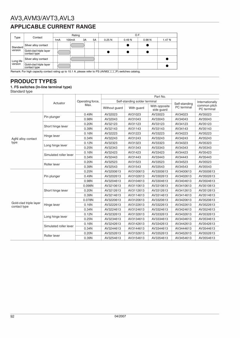
APPLICABLE CURRENT RANGE
PRODUCT TYPES1. FS switches (In-line terminal type)Standard type
Actuator Operating force, Max.
Part No.
Self-standing solder terminalSelf-standing PC terminal
Internationally common pitch PC terminalWithout guard With guard With opposite
side guard
AgNi alloy contact type
Pin plunger0.49N AV32023 AV31023 AV33023 AV34023 AV35023
0.98N AV32043 AV31043 AV33043 AV34043 AV35043
Short hinge lever0.20N AV32123 AV31123 AV33123 AV34123 AV35123
0.39N AV32143 AV31143 AV33143 AV34143 AV35143
Hinge lever0.16N AV32223 AV31223 AV33223 AV34223 AV35223
0.34N AV32243 AV31243 AV33243 AV34243 AV35243
Long hinge lever0.12N AV32323 AV31323 AV33323 AV34323 AV35323
0.25N AV32343 AV31343 AV33343 AV34343 AV35343
Simulated roller lever0.16N AV32423 AV31423 AV33423 AV34423 AV35423
0.34N AV32443 AV31443 AV33443 AV34443 AV35443
Roller lever0.20N AV32523 AV31523 AV33523 AV34523 AV35523
0.39N AV32543 AV31543 AV33543 AV34543 AV35543
Gold-clad triple layer contact type
Pin plunger
0.25N AV3200613 AV3100613 AV3300613 AV3400613 AV3500613
0.49N AV3202613 AV3102613 AV3302613 AV3402613 AV3502613
0.98N AV3204613 AV3104613 AV3304613 AV3404613 AV3504613
Short hinge lever
0.098N AV3210613 AV3110613 AV3310613 AV3410613 AV3510613
0.20N AV3212613 AV3112613 AV3312613 AV3412613 AV3512613
0.39N AV3214613 AV3114613 AV3314613 AV3414613 AV3514613
Hinge lever
0.078N AV3220613 AV3120613 AV3320613 AV3420613 AV3520613
0.16N AV3222613 AV3122613 AV3322613 AV3422613 AV3522613
0.34N AV3224613 AV3124613 AV3324613 AV3424613 AV3524613
Long hinge lever0.12N AV3232613 AV3132613 AV3332613 AV3432613 AV3532613
0.25N AV3234613 AV3134613 AV3334613 AV3434613 AV3534613
Simulated roller lever0.16N AV3242613 AV3142613 AV3342613 AV3442613 AV3542613
0.34N AV3244613 AV3144613 AV3344613 AV3444613 AV3544613
Roller lever0.20N AV3252613 AV3152613 AV3352613 AV3452613 AV3552613
0.39N AV3254613 AV3154613 AV3354613 AV3454613 AV3554613
ContactType
Standardversion
Long lifeversion
Rating O.F.
1mA 100mA 3A 5A
Silver alloy contact
Gold-clad triple layercontact type
Silver alloy contact
Gold-clad triple layercontact type
Remark: For high capacity contact rating up to 10.1 A, please refer to PS (AVM3P) switches catalog.
1.47 N0.98 N0.49 N0.25 N
Switch.book Seite 92 Donnerstag, 4. Mai 2006 10:05 10
04/2007
AV3,AVM3/AVT3,AVL3
93
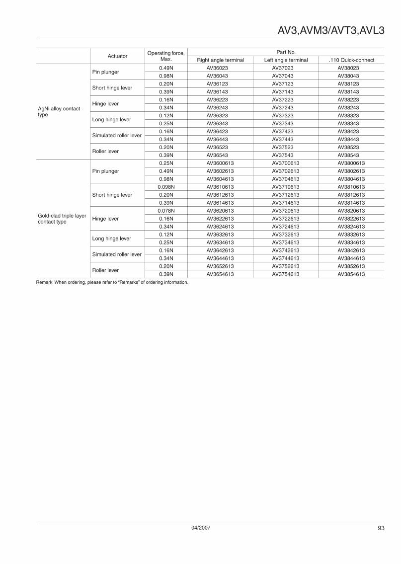
Remark: When ordering, please refer to “Remarks” of ordering information.
Actuator Operating force, Max.
Part No.
Right angle terminal Left angle terminal .110 Quick-connect
AgNi alloy contact type
Pin plunger0.49N AV36023 AV37023 AV38023
0.98N AV36043 AV37043 AV38043
Short hinge lever0.20N AV36123 AV37123 AV38123
0.39N AV36143 AV37143 AV38143
Hinge lever0.16N AV36223 AV37223 AV38223
0.34N AV36243 AV37243 AV38243
Long hinge lever0.12N AV36323 AV37323 AV38323
0.25N AV36343 AV37343 AV38343
Simulated roller lever0.16N AV36423 AV37423 AV38423
0.34N AV36443 AV37443 AV38443
Roller lever0.20N AV36523 AV37523 AV38523
0.39N AV36543 AV37543 AV38543
Gold-clad triple layer contact type
Pin plunger
0.25N AV3600613 AV3700613 AV3800613
0.49N AV3602613 AV3702613 AV3802613
0.98N AV3604613 AV3704613 AV3804613
Short hinge lever
0.098N AV3610613 AV3710613 AV3810613
0.20N AV3612613 AV3712613 AV3812613
0.39N AV3614613 AV3714613 AV3814613
Hinge lever
0.078N AV3620613 AV3720613 AV3820613
0.16N AV3622613 AV3722613 AV3822613
0.34N AV3624613 AV3724613 AV3824613
Long hinge lever0.12N AV3632613 AV3732613 AV3832613
0.25N AV3634613 AV3734613 AV3834613
Simulated roller lever0.16N AV3642613 AV3742613 AV3842613
0.34N AV3644613 AV3744613 AV3844613
Roller lever0.20N AV3652613 AV3752613 AV3852613
0.39N AV3654613 AV3754613 AV3854613
Switch.book Seite 93 Donnerstag, 4. Mai 2006 10:05 10
04/2007

AV3,AVM3/AVT3,AVL3
94
2. FS-T switches (Cross-line terminal type)Standard type
Actuator Operating force, Max.
Part No.
Solder terminal without guard PC terminal .110 Quick-connect
terminal
AgNi alloy contact type
Pin plunger0.49N AVT32023 AVT34023 AVT38023
0.98N AVT32043 AVT34043 AVT38043
Short hinge lever0.20N AVT32123 AVT34123 AVT38123
0.39N AVT32143 AVT34143 AVT38143
Hinge lever0.16N AVT32223 AVT34223 AVT38223
0.34N AVT32243 AVT34243 AVT38243
Long hinge lever0.12N AVT32323 AVT34323 AVT38323
0.25N AVT32343 AVT34343 AVT38343
Simulated roller lever0.16N AVT32423 AVT34423 AVT38423
0.34N AVT32443 AVT34443 AVT38443
Roller lever0.20N AVT32523 AVT34523 AVT38523
0.39N AVT32543 AVT34543 AVT38543
Gold-clad triple layer contact type
Pin plunger
0.25N AVT3200613 AVT3400613 AVT3800613
0.49N AVT3202613 AVT3402613 AVT3802613
0.98N AVT3204613 AVT3404613 AVT3804613
Short hinge lever
0.098N AVT3210613 AVT3410613 AVT3810613
0.20N AVT3212613 AVT3412613 AVT3812613
0.39N AVT3214613 AVT3414613 AVT3814613
Hinge lever
0.078N AVT3220613 AVT3420613 AVT3820613
0.16N AVT3222613 AVT3422613 AVT3822613
0.34N AVT3224613 AVT3424613 AVT3824613
Long hinge lever0.12N AVT3232613 AVT3432613 AVT3832613
0.25N AVT3234613 AVT3434613 AVT3834613
Simulated roller lever0.16N AVT3242613 AVT3442613 AVT3842613
0.34N AVT3244613 AVT3444613 AVT3844613
Roller lever0.20N AVT3252613 AVT3452613 AVT3852613
0.39N AVT3254613 AVT3454613 AVT3854613
Switch.book Seite 94 Donnerstag, 4. Mai 2006 10:05 10
04/2007

AV3,AVM3/AVT3,AVL3
95
3. FS switches (In-line terminal type)Long life version
Remark: When ordering, please refer to “Remarks” of ordering information.
4. FS-T switches (Cross-line terminal type)Long life version
Remark: When ordering, please refer to “Remarks” of ordering information.
Actuator Operating force, Max.
Part No.
Self-standing solder terminalSelf-standing PC terminal
Internationally common pitch PC terminalWithout guard With guard With opposite
side guard
AgNi alloy contact type
Pin plunger 1.47N AVM32053 AVM31053 AVM33053 AVM34053 AVM35053
Short hinge lever 0.59N AVM32153 AVM31153 AVM33153 AVM34153 AVM35153
Hinge lever 0.54N AVM32253 AVM31253 AVM33253 AVM34253 AVM35253
Long hinge lever 0.44N AVM32353 AVM31353 AVM33353 AVM34353 AVM35353
Simulated roller lever 0.54N AVM32453 AVM31453 AVM33453 AVM34453 AVM35453
Roller lever 0.59N AVM32553 AVM31553 AVM33553 AVM34553 AVM35553
Gold-clad triple layer contact type
Pin plunger 1.47N AVM3205613 AVM3105613 AVM3305613 AVM3405613 AVM3505613
Short hinge lever 0.59N AVM3215613 AVM3115613 AVM3315613 AVM3415613 AVM3515613
Hinge lever 0.54N AVM3225613 AVM3125613 AVM3325613 AVM3425613 AVM3525613
Long hinge lever 0.44N AVM3235613 AVM3135613 AVM3335613 AVM3435613 AVM3535613
Simulated roller lever 0.54N AVM3245613 AVM3145613 AVM3345613 AVM3445613 AVM3545613
Roller lever 0.59N AVM3255613 AVM3155613 AVM3355613 AVM3455613 AVM3555613
Actuator Operating force, Max.
Part No.
Right angle terminal Left angle terminal .110 Quick-connect
Without guard With guard With opposite side guard
AgNi alloy contact type
Pin plunger 1.47N AVM36053 AVM37053 AVM38053
Short hinge lever 0.59N AVM36153 AVM37153 AVM38153
Hinge lever 0.54N AVM36253 AVM37253 AVM38253
Long hinge lever 0.44N AVM36353 AVM37353 AVM38353
Simulated roller lever 0.54N AVM36453 AVM37453 AVM38453
Roller lever 0.59N AVM36553 AVM37553 AVM38553
Gold-clad triple layer contact type
Pin plunger 1.47N AVM3605613 AVM3705613 AVM3805613
Short hinge lever 0.59N AVM3615613 AVM3715613 AVM3815613
Hinge lever 0.54N AVM3625613 AVM3725613 AVM3825613
Long hinge lever 0.44N AVM3635613 AVM3735613 AVM3835613
Simulated roller lever 0.54N AVM3645613 AVM3745613 AVM3845613
Roller lever 0.59N AVM3655613 AVM3755613 AVM3855613
Actuator Operating force, Max.
Part No.
Solder terminal Without guard PC terminal .110 Quick-connect
terminal
AgNi alloy contact type
Pin plunger 1.47N AVL32053 AVL34053 AVL38053
Short hinge lever 0.59N AVL32153 AVL34153 AVL38153
Hinge lever 0.54N AVL32253 AVL34253 AVL38253
Long hinge lever 0.44N AVL32353 AVL34353 AVL38353
Simulated roller lever 0.54N AVL32453 AVL34453 AVL38453
Roller lever 0.59N AVL32553 AVL34553 AVL38553
Gold-clad triple layer contact type
Pin plunger 1.47N AVL3205613 AVL3405613 AVL3805613
Short hinge lever 0.59N AVL3215613 AVL3415613 AVL3815613
Hinge lever 0.54N AVL3225613 AVL3425613 AVL3825613
Long hinge lever 0.44N AVL3235613 AVL3435613 AVL3835613
Simulated roller lever 0.54N AVL3245613 AVL3445613 AVL3845613
Roller lever 0.59N AVL3255613 AVL3455613 AVL3855613
Switch.book Seite 95 Donnerstag, 4. Mai 2006 10:05 10
04/2007

AV3,AVM3/AVT3,AVL3
96
SPECIFICATIONS1.Contact rating
Remark: Time constant shall be less than 7 msec. for DC inductive loads.
2.Characteristics
3.Operating characteristics1) Pin plunger
2) Short hinge lever
Voltage
Standard version Long life version
AgNi alloy contact typeGold-clad contact
type AgNi alloy contact typeGold-clad contact
type
Triple layer Triple layer
Resistive load (cosφ]1)
Inductive load (cosφ]0.6-0.7)
Resistive load (cosφ]1)
Resistive load (cosφ]1)
Inductive load (cosφ]0.6-0.7)
Resistive load (cosφ]1)
125V AC 3A 2A 0.1A 5A 3A 0.1A
250V AC 3A 2A 0.1A 5A 3A 0.1A
30V DC 3A 2A 0.1A 5A 3A 0.1A
125V DC 0.4A 0.05A — 0.4A 0.05A —
Standard version Long life version
AgNi alloy contact type Gold-clad contact type AgNi alloy contact type Gold-clad contact type
Electrical life at rated load (O.T.max.) 5 × 10⁴ at 20 cpm 2 × 10⁵ at 20 cpm 5 × 10⁴ at 20 cpm 2 × 10⁵ at 20 cpm
Mechanical life 5 × 10⁵ at 60 cpm (O.T.max.) 3 × 10⁷ (O.T.: Specified value) 107 (O.T.max.) at 60 cpm
Insulation resistance Min.100MΩ at 500V DC
Dielectric strength Between non-continuous terminals Between each terminal and other exposed metal parts Between each terminal and ground
1,000 Vrms
1,500 Vrms1,500 Vrms
Vibration resistance (Pin plunger type) 10 to 55 Hz at single amplitude of 1.5mm (Contact opening: max.1 msec.)
Shock resistance (Pin plunger type) (Contact opening: less than 1 msec.)
294 m/s2 min. (O.F. 0.98 N)147 m/s2 min. (O.F. 0.49 N)
294 m/s2 min. (O.F. 0.98 N)147 m/s2 min. (O.F. 0.49 N)49 m/s2 min. (O.F. 0.25 N)
294 m/s2 min.
Contact resistance (Initial)50 mΩ max.
(by voltage drop 1 A 6 to 8V DC)
100 mΩ max. (by voltage drop 0.1 A
6 to 8V DC)
Au: 50 mΩ max. (by voltage drop 0.1 A 6 to 8V DC)Ag: 50 mΩ max. (by voltage drop 1 A 6 to 8V DC)
Allowable operating speed 0.1 to 1,000 mm/sec.
Max.operating cycle rate 300 cpm
Ambient temeprature –25°C to +85°C (no freezing below 0°C)
Unit weight Approx.2g
4th digit number of Part No.
O.F.max. R.F.min. P.T.max. M.D.max. O.T.max. O.P.
0 0.25N 0.020N
0.6mm 0.1mm 0.4mm
Distance from mounting holes: 8.4±0.3mmDistance from stand-off:FS 11.8±0.4mmFS-T 11.7±0.4mm
2 0.49N 0.074N
4 0.98N 0.15N
5 1.47N 0.20N
4th digit number of Part No.
O.F.max. R.F.min. P.T.max. M.D.max. O.T.max. O.P.
0 0.098N 0.004N
2.5mm 0.5mm 0.8mm
Distance from mounting holes: 8.8±0.8mmDistance from stand-off:FS 12.2±0.9mmFS-T 12.1±0.9mm
2 0.20N 0.017N
4 0.39N 0.034N
5 0.59N 0.039N
Switch.book Seite 96 Donnerstag, 4. Mai 2006 10:05 10
04/2007

AV3,AVM3/AVT3,AVL3
97
3) Hinge lever
4) Long hinge lever
5) Simulated roller lever
6) Roller lever
DIMENSIONS mm General tolerance: ±0.25
4th digit number of Part No.
O.F.max. R.F.min. P.T.max. M.D.max. O.T.max. O.P.
0 0.078N 0.003N
2.8mm 0.8mm 1.2mm
Distance from mounting holes: 8.8±0.8mmDistance from stand-off:FS 12.2±0.9mmFS-T 12.1±0.9mm
2 0.16N 0.015N
4 0.34N 0.029N
5 0.54N 0.034N
4th digit number of Part No.
O.F.max. R.F.min. P.T.max. M.D.max. O.T.max. O.P.
0 — —
3.5mm 1.0mm 1.6mm
Distance from mounting holes: 8.8±1.2mmDistance from stand-off:FS 12.2±1.3mmFS-T 12.1±1.3mm
2 0.12N 0.012N
4 0.25N 0.025N
5 0.44N 0.029N
4th digit number of Part No.
O.F.max. R.F.min. P.T.max. M.D.max. O.T.max. O.P.
0 — —
2.8mm 0.8mm 1.2mm
Distance from mounting holes: 11.65±0.8mmDistance from stand-off:FS 15.05±0.9mmFS-T 14.95±0.9mm
2 0.16N 0.015N
4 0.34N 0.029N
5 0.54N 0.034N
4th digit number of Part No.
O.F.max. R.F.min. P.T.max. M.D.max. O.T.max. O.P.
0 — —
2.5mm 0.5mm 0.8mm
Distance from mounting holes: 14.5±0.8mmDistance from stand-off:FS 17.9±0.9mmFS-T 17.8±0.9mm
2 0.20N 0.017N
4 0.39N 0.034N
5 0.59N 0.039N
1. FS switches (In-line terminal type)1-(1) Solder terminal (without guard)
1.250.5
7.4
2.8
NCNO
C
±0.153.4
±0.2
±0.1
1.5
1.1
6.4
5.2
4.0
19.8
15.4
8.7 ±0.15
±0.15
±0.3
±0.12
±0.12
1.85 ±0.2
±0.2
Dimensions other than drawn above is same as self-standing PC board terminal.
Switch.book Seite 97 Donnerstag, 4. Mai 2006 10:05 10
04/2007

AV3,AVM3/AVT3,AVL3
98
1-(2) Solder terminal (with guard)
8.0
24.0
NCNO
C
Dimensions other than drawn above is same as guardless type.
mm General tolerance: ±0.25
1-(3) Solder terminal (with opposite side guard)
8.0
24.0
Dimensions other than drawn above is same as guardless type.
1-(4) Self-standing PC terminalPin plunger
0.6 max.
2.4
9.5
NCNO
C
7.6
1.8
1.5
1.1
6.4
5.2
1.25
0.5
4.0
11.88.4 (O.P.)
(P.T.)
7.4
6.77.7-0.05+0.12.4
0.9
2.2
19.815.4
8.7
2.5
±0.3
±0.1
±0.1
±0.15
±0.15
±0.3
2.2 ±0.1
±0.15
(O.P.)
±0.4
±0.3
3.4
±0.12
±0.12
1.85 ±0.2
±0.2
±0.1
2.4 dia.+0.1-0.05
PC board pattern
Pretravel, Max. mm 0.6Movement differential, Max. mm 0.1Overtravel, Min. mm 0.4
Operating position
Distance from mounting hole, mm 8.4±0.3
Distance from standoff, mm 11.8±0.4
3-1.2±0.05 dia.
8.7±0.1
15.4±0.1
Short hinge lever
12.85 5.0
NCNO
C
±0.4
2.5 max.
6.6
4.0
12.2(O.P.)
(P.T.)
±0.98.8(O.P.)
±0.8
Pretravel, Max. mm 2.5Movement differential, Max. mm 0.5Overtravel, Min. mm 0.8
Operating position
Distance from mounting hole, mm 8.8±0.8
Distance from standoff, mm 12.2±0.9
Hinge lever
NCNO
C
7.15 ±0.4
2.8 max.4.0
12.2(O.P.)
(P.T.)
±0.98.8(O.P.)
±0.8
Pretravel, Max. mm 2.8Movement differential, Max. mm 0.8Overtravel, Min. mm 1.2
Operating position
Distance from mounting hole, mm 8.8±0.8
Distance from standoff, mm 12.2±0.9
Switch.book Seite 98 Donnerstag, 4. Mai 2006 10:05 10
04/2007
AV3,AVM3/AVT3,AVL3
99
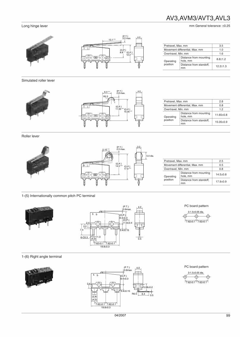
Long hinge lever
NCNO
C
13.1 ±0.4 3.5 max. 4.0
12.2(O.P.)
(P.T.)
±1.38.8(O.P.)
±1.2
Pretravel, Max. mm 3.5Movement differential, Max. mm 1.0Overtravel, Min. mm 1.6
Operating position
Distance from mounting hole, mm 8.8±1.2
Distance from standoff, mm 12.2±1.3
mm General tolerance: ±0.25
Simulated roller lever
R2.5
NCNO
C
6.3 ±0.4
2.8 max.4.0(P.T.)
15.05(O.P.)
±0.9
11.65(O.P.)
±0.8
Pretravel, Max. mm 2.8Movement differential, Max. mm 0.8Overtravel, Min. mm 1.2
Operating position
Distance from mounting hole, mm 11.65±0.8
Distance from standoff, mm 15.05±0.9
Roller lever
3.2
5.0 dia.
NCNO
C
5.15 ±0.4 2.5 max.
17.9(O.P.)
(P.T.)
±0.9
14.5(O.P.)
±0.8
Pretravel, Max. mm 2.5Movement differential, Max. mm 0.5Overtravel, Min. mm 0.8
Operating position
Distance from mounting hole, mm 14.5±0.8
Distance from standoff, mm 17.9±0.9
1-(5) Internationally common pitch PC terminal
(P.T.)0.6max.
4.0
2.4
1.3(4.0)
3.27.4
6-C0.3
7.62±0.119.8±0.3
7.62±0.1
(O.P.)8.4±0.3
(O.P.)11.8±0.4
3.4±0.15
0.5
PC board pattern
3-1.5±0.05 dia.
7.62±0.1 7.62±0.1
1-(6) Right angle terminal
(P.T.)0.6max.
4.0
2.4
(4.0)(2.8)
7.62±0.119.8±0.3
7.62±0.1
(O.P.)8.4±0.3
3.4±0.156.4 0.5
R0.5
5.08±0.2
PC board pattern
3-1.5±0.05 dia.
7.62±0.1 7.62±0.1
Switch.book Seite 99 Donnerstag, 4. Mai 2006 10:05 10
04/2007

AV3,AVM3/AVT3,AVL3
100
1-(7) Left angle terminal
(P.T.)0.6max.
4.0
2.4
(4.0)(2.8)
7.62±0.119.8±0.3
7.62±0.1
(O.P.)8.4±0.3
3.4±0.156.40.5
R0.5
5.08±0.2
PC board pattern
3-1.5±0.05 dia.
7.62±0.1 7.62±0.1
mm General tolerance: ±0.25
1-(8) .110 Quick-connect terminal
3-1.2 dia. 2.8
-0.1504.0
15.2
5.5
NCNO
C
±0.1
7.1 ±0.15
±0.15
±0.15
±0.05±0.1
6-C0.6±0.1
7.6
0.5
±0.153.4
6.4
5.2
4.0
±0.2
9.5
19.8
2.5 ±0.1
±0.1
±0.3
11.0
Dimensions other than drawn above is same as self-standing PC board terminal.
2.FS-T switches (Cross-line terminal type)2-(1) PC board terminalPin plunger
6.4
3.27.0
1.20.5
16.1
8.8
19.8
NONCC
±0.3
±0.2
±0.1
0.6 max.
2.4
9.5
7.6 4.0
8.4
(P.T.)
6.77.7
3.3
-0.05+0.12.4
2.5
±0.3
±0.1
±0.1
(O.P.)±0.3
2.4 dia.+0.1-0.05
PC board pattern
10.9(Button position)
8.8±0.1
16.1±0.1
3-1.35 to 1.50 dia.
Pretravel, Max. mm 0.6Movement differential, Max. mm 0.1Overtravel, Min. mm 0.4
Operating position
Distance from mounting hole, mm 8.4±0.3
Distance from standoff, mm 11.7±0.4
Short hinge lever
NONCC
12.85 5.0 ±0.4
2.5 max.4.0(P.T.)
8.8(O.P.)
±0.8
Pretravel, Max. mm 2.5Movement differential, Max. mm 0.5Overtravel, Min. mm 0.8
Operating position
Distance from mounting hole, mm 8.8±0.8
Distance from standoff, mm 12.1±0.9
Switch.book Seite 100 Donnerstag, 4. Mai 2006 10:05 10
04/2007

AV3,AVM3/AVT3,AVL3
101
Hinge lever
NONCC
7.15 ±0.4
2.8 max.4.0(P.T.)
8.8(O.P.)
±0.8
12.85
Pretravel, Max. mm 2.8Movement differential, Max. mm 0.8Overtravel, Min. mm 1.2
Operating position
Distance from mounting hole, mm 8.8±0.8
Distance from standoff, mm 12.1±0.9
mm General tolerance: ±0.25
Long hinge lever
NONCC
13.1 ±0.4 3.5 max. 4.0(P.T.)
8.8(O.P.)
±1.2
Pretravel, Max. mm 3.5Movement differential, Max. mm 1.0Overtravel, Min. mm 1.6
Operating position
Distance from mounting hole, mm 8.8±1.2
Distance from standoff, mm 12.1±1.3
Simulated roller lever
NONCC
R2.56.3 ±0.4 2.8 max.
4.0(P.T.)
11.65(O.P.)
±0.8
12.85
Pretravel, Max. mm 2.8Movement differential, Max. mm 0.8Overtravel, Min. mm 1.2
Operating position
Distance from mounting hole, mm 11.65±0.8
Distance from standoff, mm 14.95±0.9
Roller lever
NONCC
3.2
5.0 dia.
5.15 ±0.4
2.5 max.(P.T.)
14.5(O.P.)
±0.8
Pretravel, Max. mm 2.5Movement differential, Max. mm 0.5Overtravel, Min. mm 0.8
Operating position
Distance from mounting hole, mm 14.5±0.8
Distance from standoff, mm 17.8±0.9
2-(2) Solder terminal
16.1
8.8
NONCC
6.4
1.8 dia.
6-C 0
.3
(3.9)
2.8±0.2
6.4
4.0
1.5
±0.2
0.6 max.
2.4
9.5
7.6
0.5
8.4
(P.T.)
6.77.7
3.3
-0.05+0.12.4
2.5
±0.3
±0.1
±0.1
(O.P.)±0.3
2.4 dia.+0.1-0.05
19.8 ±0.3
As for the dimensions of lever types, dimensions other than terminals are same as self-standing solder terminal.
Switch.book Seite 101 Donnerstag, 4. Mai 2006 10:05 10
04/2007

AV3,AVM3/AVT3,AVL3
102
NOTES
2-(3) .110 Quick-connect terminal
5.5 7.111.0
16.1
8.8
NONCC
±0.1±0.15
0.6 max.
2.4
9.5
7.6
6.4
2.80.5
4.0
8.4
(P.T.)
6.77.7
3.3
-0.05+0.12.4
2.5
±0.3
±0.1
±0.1
(O.P.)±0.3
±0.2
±0.1
2.4 dia.+0.1-0.05
1.2 dia.±0.05
19.8 ±0.3
As for the dimensions of lever types, dimensions other than terminals are same as self-standing solder terminal.
mm General tolerance: ±0.25
1.Regarding fastening of switch bodyIn fastening the switch body, use flat filister head M2.3 screws, with tightening torque of not more than 0.29N·m.To prevent loosening of the screws, it is recommended that spring washers be used with the screws and adhesive be applied to lock the screws.After mounting the switch and making wiring connections, the insulation distance between ground and each terminal should be confirmed as sufficient. The positioning of the switch should be such that the pushbutton or actuator for the switch should not directly apply force to the operating section in the free condition.For a pushbutton, the force from the pushbutton should be applied in a perpendicular direction.In setting the movement after operation, the over-travel should be set not less than 70% as a standard.Setting the movement at less than 70% of O.T.may cause troubles such as mis-contact and welding due to small contact force of the switch.
2.Soldering operation
For manual soldering: 60W soldering iron, soldering completed within 3 seconds; do not apply force to the terminals.For automatic soldering tank: 250°C immersion, completed within 6 seconds, 350°C immersion, completed within 3 seconds.Terminal portions must not be moved in min.1 minute after soldering.Also no tensile strength of lead wires should be applied to terminals.3.Regarding connector connections (.110 quick connect terminals) For making connections, a dedicated receptacle for .110 quick connect terminals should be used, and the terminals should be inserted parallel to the receptacle.Consideration should be given to mounting so that no tensile load is applied to the lead wires. 4.In making the switch selection Consideration should be given to provide for no interference up to +20% variation of the standard characteristics values.5.Environment Locations where corrosive gases having a bad influence on contacts are present, and locations where there is an excessive amount of siliceous or other abrasive dust should be avoided.
6.Cautions regarding use
This subminiature switch has been designed as a dedicated switch for AC use, but it can be used for low capacity DC circuits.Please select gold-clad contact types when loads are in the low-level area of 1mA up to 100mA and 5V up to 30V.
For switching of inductive loads (relays, solenoids, buzzers, etc.), in order to prevent damage to contacts due to the occurrence of arcing, an arc absorbing circuit should be applied7.Quality check under Actual Loading ConditionTo assure reliability, check the switch under actual loading conditions.Avoid any situation that may adversely affect switching performance.8.When using lever type switch, care should be taken not to apply undue force on the body from the opposite side or side ways to its operating direction.
N.C.side
N.O.side
Contactforce
Stroke
0
O.T. max.
Usablearea
P.T.
O.T. spedifiedvalue
70% of O.T.specified value
Ag
Au (-61)Triple layer contact type
3 A
100 mA
1 mA
0DCAC
(Reference only)
55
15 30V30 250V
Switch.book Seite 102 Donnerstag, 4. Mai 2006 10:05 10
04/2007

AV3G
103
ORDERING INFORMATION
PRODUCT TYPES
Remark: Unless you request otherwise, the switch comes with a stamp indicating its conformance to standards.
SPECIFICATIONS1. Contact rating• Silver alloy contact type
SUBMINIATURE SWITCHES (Contact gap:
more than 1mm type)
AV3G (FS)SWITCHES
Actuator Operating forceMax.
Solder terminalPC board terminal .110 Quick- connect terminal
Without guard
Pin plunger 1.47 N AV3205G3 AV3405G3 AV3805G3
Short hinge lever 0.59 N AV3215G3 AV3415G3 AV3815G3
Hinge lever 0.54 N AV3225G3 AV3425G3 AV3825G3
Long hinge lever 0.44 N AV3235G3 AV3435G3 AV3835G3
Simulated roller lever 0.54 N AV3245G3 AV3445G3 AV3845G3
Roller lever 0.59 N AV3255G3 AV3455G3 AV3855G3
Voltage Resistive road (cos φ]1)
30 V DC 3 A
VDE
FEATURES• Conforming to IEC950• Contact gap of greater than 1mm• UL/CSA/VDE/SEMKO under application
TYPICAL APPLICATIONS• Office equiment (printers, copiers)
RoHS Directive compatibility informationhttp://www.nais-e.com/
Type of switch
FS switch
Terminals Actuators
2:
4:
8:
Self-standing solderterminal without guardSelf-standing PC terminal.110 Quick-connectterminal
0:1:2:3:4:5:
Pin plungerShort hinge leverHinge leverLong hinge leverSimulated roller leverRoller lever
Version
3: Standard
Operating forceby pin plunger, max.
5: 1.47 N
Contact gap
G: More than 1 mm type
Agencystandard
3: UL/CSA/TÜV/SEMKO
Ex. AV 3 2 5 5 G 3
Switch.book Seite 103 Donnerstag, 4. Mai 2006 10:05 10
04/2007

AV3G
104
2. Characteristics
Remark: Test conditions are in accordance with JIS C 4505.
3. Operating characteristics
DIMENSIONSThe same size as the standard FS/FS-T switches. Please refer to “FS/FS-T switches pages” or our web site. URL: http://www.nais-e.com/
Item Characteristics
Expected lifeMechanical (O.T.: Specified value) Min. 5 × 10⁵ (at 60cpm)
Electrical (O.T. max.) Min. 104 (at 20cpm)
Breakdown voltage
Between non-continuous terminals 1,000 Vrms for 1 min. (at 10mA)
Between each terminal and other exposed metal parts 2,000 Vrms for 1 min. (at 10mA)
Between each terminal and ground 2,000 Vrms for 1 min. (at 10mA)
Insulation resistance Min. 100MΩ (at 500 V DC)
Contact resistance (Initial) Max. 50mΩ (by voltage drop 6 to 8 V DC 1A)
Vibration resistance 10 to 55 Hz at single amplitude of 0.75 mm (Contact opening: Max. 1 msec.)
Shock resistancePin plunger type 294m/s2 (Contact distance: Max. 1 msec.)
Lever type 147m/s2 (Contact distance: Max. 1 msec.)
Allowable operation speed (No load) 0.1 to 1,000 mm/s
Max. switching frequency (No load) 300 cpm.
Ambient temperature –25°C to +85°C (Not freezing below 0°C)
Actuator Operating force, Max.
Release force, Min.
Pretravel, Max. mm
Movement differential, Max. mm
Overtravel, Min. mm
Operating position,
mm
Pin plunger 1.47 N 0.064 N 0.7 0.2 0.3 8.4±0.3
Short hinge lever 0.59 N 0.015 N 2.5 0.8 0.6 8.8±0.8
Hinge lever 0.54 N 0.013 N 2.8 1.0 0.8 8.8±0.8
Long hinge lever 0.44 N 0.0098 N 3.5 1.2 1.2 8.8±1.2
Simulated roller lever 0.54 N 0.013 N 2.8 1.0 0.8 11.65±0.8
Roller lever 0.59 N 0.015 N 2.5 0.8 0.6 14.5±0.8
Switch.book Seite 104 Donnerstag, 4. Mai 2006 10:05 10
04/2007

AVM3P
105
ORDERING INFORMATION
HIGH CAPACITY, LONG LIFE SUBMINIATURE
SWITCH
AVM3P (PS)SWITCHES
RoHS Directive compatibility informationhttp://www.nais-e.com/
FEATURES• 10.1 Amp. high contact capacity is
available• Long life• Precise operating position
(±0.25mm: Pin plunger type)• Flux-resistant construction with
integrally molded terminals• In-line terminals make soldering
works easy• UL/CSA/SEMKO approved
TYPICAL APPLICATIONS• Heaters• Electric rice cookers• Copiers• Printers• Facsimiles• Vending machines• Measuring equipment• Audio equipment
Type of switch
PS switch
Actuators
0:1:2:3:4:5:
Pin plungerShort hinge leverHinge leverLong hinge leverSimulated roller leverRoller lever
Terminals
1:
2:
3:
4:
Self-standing solder terminal with guardSelf-standing solder terminal without guardSelf-standing solder terminal with opposite side guardSelf-standing PC terminal
Operating forceby pin plunger, max.
5: 1.47 N
Capacity
P: High capacity(10.1 A)
Agencystandard
3: UL/CSA/SEMKO
Ex. AVM3 1 0 5 P 3
CONSTRUCTION CONTACT ARRANGEMENT: SPDT
DATAElectrical life curve
COM NO NC
30
10
20
3
5
10 5 10
Load current (A)
No.
of o
pera
tions
, ×10
4
Switch.book Seite 105 Donnerstag, 4. Mai 2006 10:05 10
04/2007

AVM3P
106
PRODUCT TYPES
SPECIFICATIONS1. Contact rating
2. Characteristics
3. Operating characteristics
DIMENSIONS mm General tolerance: ±0.25
Contact Actuator
Part No.
Self-standing solder terminalSelf-standing PC terminalWithout guard With guard With opposite
side guard
Gold-clad
Pin plunger AVM3205P3 AVM3105P3 AVM3305P3 AVM3405P3
Short hinge lever AVM3215P3 AVM3115P3 AVM3315P3 AVM3415P3
Hinge lever AVM3225P3 AVM3125P3 AVM3325P3 AVM3425P3
Long hinge lever AVM3235P3 AVM3135P3 AVM3335P3 AVM3435P3
Simulated roller lever AVM3245P3 AVM3145P3 AVM3345P3 AVM3445P3
Roller lever AVM3255P3 AVM3155P3 AVM3355P3 AVM3455P3
Resistive load (cos φ ] 1) 10.1A, 250V AC
Expected lifeElectrical Min. 5 × 10⁴ (at 20 cpm) (O.T. max.)
Mechanical Min. 3 × 10⁷ (O.T.: Specified value), at 60 cpm
Dielectric strength
Between terminals 1,000 Vrms for 1 min. (at 10 mA)
Between terminals and other exposed metal parts 2,000 Vrms for 1 min. (at 10 mA)
Between terminals and ground 2,000 Vrms for 1 min. (at 10 mA)
Insulation resistance Min. 100MΩ (at 500V DC)
Contact resistance (initial) Max. 50mΩ (By voltage drop, 1A 6 to 8V DC)
Allowable operating speed (at no load) 0.1 to 1,000 mm/sec.
Max. operating cycle rate (at no load) 300 cpm
Ambient temperature –25 to +85°C (Not freezing below 0°C)
Unit weight Approx. 2g
Contact material AgNi alloy
Actuator Operating force,Max.
Release force,Min.
Pretravel, Max. mm
Movement differential, Max. mm
Overtravel, Min. mm
Operating position mm
Pin plunger 1.47 N 0.20 N 0.6 mm 0.1 mm 0.4 mm 8.4±0.25 mm
Short hinge lever 0.59 N 0.039 N 2.5 mm 0.5 mm 0.8 mm 8.8±0.8 mm
Hinge lever 0.54 N 0.034 N 2.8 mm 0.8 mm 1.2 mm 8.8±0.8 mm
Long hinge lever 0.44 N 0.029 N 3.5 mm 1.0 mm 1.6 mm 8.8±1.2 mm
Simulated roller lever 0.54 N 0.034 N 2.8 mm 0.8 mm 1.2 mm 11.65±0.8 mm
Roller lever 0.59 N 0.039 N 2.5 mm 0.5 mm 0.8 mm 14.5±0.8 mm
1. Self-standing PC terminal (Without guard)Pin plunger
2.2
NONCC
0.5
0.6 max.
8.7
15.4
0.9
7.4
0.75
9.5
1.8
6.4
5.21.25
0.5
4.0
(P.T.)
7.7 -0.05+0.12.4
2.4
19.8
2.5
7.6 ±0.3
±0.1
±0.15
±0.15
±0.3
±0.1
2.2 ±0.1
±0.153.4
±0.1
±0.2
1.1 ±0.12
1.5 ±0.12
1.85 ±0.2
6.7 8.4 ±0.25(O.P.)
11.8(O.P.)
±0.35
2.4 dia.+0.1-0.05
PC board pattern
8.7 ±0.15
15.4 ±0.1
Pin plunger position(10.55)
3-1.2 dia.±0.05
Pretravel, Max. mm 0.6Movement differential, Max. mm 0.1
Overtravel, Min mm 0.4
Operating position
Distance from mounting hole, mm
8.4±0.25
Switch.book Seite 106 Donnerstag, 4. Mai 2006 10:05 10
04/2007
AVM3P
107
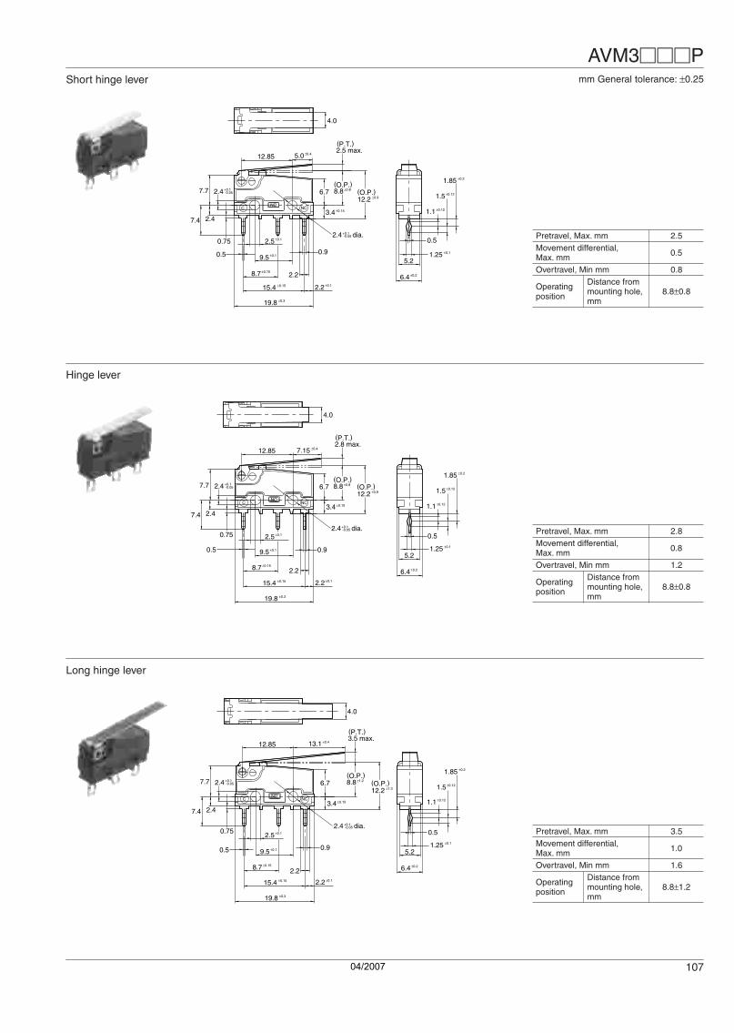
Short hinge lever
12.85
NONCC
5.0 ±0.42.5 max.
6.4
5.21.25
0.5
4.0
(P.T.)
±0.1
±0.2
1.1 ±0.12
1.5 ±0.12
1.85 ±0.2
2.2
0.5
8.7
15.4
0.9
7.4
0.75
9.5
7.7 -0.05+0.12.4
2.4
19.8
2.5
±0.1
±0.15
±0.15
±0.3
±0.1
2.2 ±0.1
±0.153.4
6.7 8.8 ±0.8(O.P.)
12.2(O.P.)
±0.9
2.4 dia.+0.1-0.05 Pretravel, Max. mm 2.5
Movement differential, Max. mm 0.5
Overtravel, Min mm 0.8
Operating position
Distance from mounting hole, mm
8.8±0.8
mm General tolerance: ±0.25
Hinge lever
NONCC
7.15 ±0.412.852.8 max.
6.4
5.21.25
0.5
4.0
(P.T.)
±0.1
±0.2
1.1 ±0.12
1.5 ±0.12
1.85 ±0.2
2.2
0.5
8.7
15.4
0.9
7.4
0.75
9.5
7.7 -0.05+0.12.4
2.4
19.8
2.5
±0.1
±0.15
±0.15
±0.3
±0.1
2.2 ±0.1
±0.153.4
6.7 8.8 ±0.8(O.P.)
12.2(O.P.)
±0.9
2.4 dia.+0.1-0.05 Pretravel, Max. mm 2.8
Movement differential, Max. mm 0.8
Overtravel, Min mm 1.2
Operating position
Distance from mounting hole, mm
8.8±0.8
Long hinge lever
NONCC
13.1 ±0.412.853.5 max.
6.4
5.21.25
0.5
4.0
(P.T.)
±0.1
±0.2
1.1 ±0.12
1.5 ±0.12
1.85 ±0.2
2.2
0.5
8.7
15.4
0.9
7.4
0.75
9.5
7.7 -0.05+0.12.4
2.4
19.8
2.5
±0.1
±0.15
±0.15
±0.3
±0.1
2.2 ±0.1
±0.153.4
6.7 8.8 ±1.2(O.P.)
12.2(O.P.)
±1.3
2.4 dia.+0.1-0.05
Pretravel, Max. mm 3.5Movement differential, Max. mm 1.0
Overtravel, Min mm 1.6
Operating position
Distance from mounting hole, mm
8.8±1.2
Switch.book Seite 107 Donnerstag, 4. Mai 2006 10:05 10
04/2007

AVM3P
108
Simulated roller lever mm General tolerance: ±0.25
R2.5
NONCC
6.3 ±0.412.852.8 max.
6.4
5.21.25
0.5
4.0
(P.T.)
±0.1
±0.2
1.1 ±0.12
1.5 ±0.12
1.85 ±0.2
2.2
0.5
8.7
15.4
0.9
7.4
0.75
9.5
7.7 -0.05+0.12.4
2.4
19.8
2.5
±0.1
±0.15
±0.15
±0.3
±0.1
2.2 ±0.1
±0.153.4
6.7
2.4 dia.+0.1-0.05
11.65 ±0.8(O.P.)
15.05(O.P.)
±0.9
Pretravel, Max. mm 2.8Movement differential, Max. mm 0.8
Overtravel, Min mm 1.2
Operating position
Distance from mounting hole, mm
11.65±0.8
Roller lever
3.2
5.0 dia.
NONCC
2.5 max.
6.4
5.21.25
0.5
(P.T.)
±0.1
±0.2
1.1 ±0.12
1.5 ±0.12
1.85 ±0.2
2.2
0.5
8.7
15.4
0.9
7.4
0.75
9.5
7.7 -0.05+0.12.4
2.4
19.8
2.5
±0.1
±0.15
±0.15
±0.3
±0.1
2.2 ±0.1
±0.153.4
6.7
2.4 dia.+0.1-0.05
14.5 ±0.8(O.P.)
17.9(O.P.)
±0.9
5.15 ±0.412.85
Pretravel, Max. mm 2.5Movement differential, Max. mm 0.5
Overtravel, Min mm 0.8
Operating position
Distance from mounting hole, mm
14.5±0.8
2. Self-standing solder terminalPin plunger
0.6 max.
8.7
15.4
R0.8
2.4
2.8
7.4
9.5
1.8
6.4
5.21.25
0.5
4.0
(P.T.)
7.7 -0.05+0.12.4
2.4
19.8
2.5
NONCC
7.6 ±0.3
±0.1
±0.15
±0.15
±0.3
±0.2
2.2
±0.1
±0.153.4R0.6
±0.1
±0.2
1.1 ±0.12
1.5 ±0.12
1.85 ±0.2
6.7 8.4 ±0.25(O.P.)
11.8(O.P.)
±0.35
2.4 dia.+0.1-0.05
With guard
8* 24
With opposite side guard
24
8*
* The height from the center of mounting hole to the edge of guard.
Switch.book Seite 108 Donnerstag, 4. Mai 2006 10:05 10
04/2007

AVM3P
109
NOTES1. Fastening of the switch body1) Use flat filister head M2.3 screws to mount switches with less than a 0.29 N·m torque. Use of screws washers or adhesive lock is recommended to prevent loosening of the screws.2) Check insulation distance between ground and each terminal.3) When the operation object is in the free position, force should not be applied directly to the actuator or pin plunger from vertical direction to the switch.4) In setting the movement after operation, the over-travel should be set more than 70% as a standard. Setting the movement at less than 70% of O.T. may cause troubles such as miscontact and welding due to small contact force of the switch.5) For a lever type, the force from the reverse and side to the operation direction should not be applied.
2. Soldering operationsFor manual soldering:Soldering should be accomplished in less than 3 seconds, with a 60 watt iron. Care should be taken not to apply force to the terminal during soldering.For automatic soldering:Soldering should be done less than 6 seconds in 260°C soldering bath or less than 3 seconds in 350°C soldering bath.Terminal portions should not be moved within 1 minute after soldering.Also no tensile strength of lead wires should be applied to the terminals.3. Selection of the switchWhen specifying the switch, allow ±20% to the listed operating characteristics.4. EnvironmentAvoid using the switches in the following conditions;• In corrosive gases, such as silicon gas• In a dusty environment
5. Cautions regarding useWhen switching low-level circuits (6V DC 5mA, 12V DC 2mA, 24V DC 1mA), AV, AV3/AVT3, AVL3 Au clad contact type switches are recommended. When used to switch inductive loads (relays, solenoids, buzzers, etc.), it is recommended that a proper spark quench circuit is inserted in the switch to prevent contact faults caused by electric arcs. Care should be taken that occurrence in AC load possibly shorten the expected life.6. Quality check under actual loading conditionsTo assure reliability, check the switch under actual loading conditions. Avoid any situation that may adversely affect switching performance.
Switch.book Seite 109 Donnerstag, 4. Mai 2006 10:05 10
04/2007

AV6
110
ORDERING INFORMATION
S Model Switch Connector Type
AV6 (CS) SWITCHES
FEATURES• Using a connector for connections significantly improves operation effectiveness.Applicable connector:XA connector produced by JST Mfg. Co., Ltd.- Contact: SXA-001T-P0.6- Housing: XAP-02V-1
• Contact reliability is achived by simple dust prevension guard and gold-clad double layer contacts
• The contact arrangement is available in two types, the SPST-NC and the SPST-NO.
• The lever position is available in two types.
Standard lever position
“Standard lever position” refers to a position in which the lever is installed with the plunger close to the reference.
Backward lever position
“Backward lever position” refers to a position in which the lever is installed with the plunger far away from the reference.
TYPICAL APPLICATIONS• Detection of vending machine condition whether cans are out of stock• Ball detection of pinball game machine• PPC (Plain Paper Copier)• LBP (Laser Beam Printer)
RoHS Directive compatibility informationhttp://www.nais-e.com/
Connector
A
A
A-A cross-section(internal parts omitted)(with cap removed)
Gold-clad
Copper alloy(SPST-NC)
Gold clad doublelayer contacts
Type of switch
AV6: CS switch
Actuators
0:2:4:5:
Pin plungerHinge leverSimulated roller leverRoller lever
O.F.(by pin plunger)
2:5:
0.50 N1.50 N
Contact arrangement
2:3:
SPST-NCSPST-NO
Lever position
Nil:12:
StandardBackward
Contacts
64: Gold clad double layer
Ex. AV6 2 2 2 12 64
Remarks: 1. Standard packing Inner carton: 100 pcs. Outer carton: 1,000 pcs.2. When ordering UL, CSA and TÜV approved types, please attach suffix “3” to the part no.
Switch.book Seite 110 Donnerstag, 4. Mai 2006 10:05 10
04/2007

AV6
111
PRODUCT TYPES1. Lever position: Standard
Remarks: 1. When ordering UL, CSA and TÜV approved (under application) types, please attach suffix "3" to the part no.
2. Lever position: Backward
Remarks: 1. When ordering UL, CSA and TÜV approved (under application) types, please attach suffix "3" to the part no.
SPECIFICATIONS1. Contact rating
2. Characteristics
Actuator Operating force, Max.Contact arrangement
SPST-NC SPST-NO
Pin plunger0.50N AV620264 AV630264
1.50N AV620564 AV630564
Hinge lever0.20N AV622264 AV632264
0.50N AV622564 AV632564
Simulated roller lever0.20N AV624264 AV634264
0.50N AV624564 AV634564
Roller lever0.20N AV625264 AV635264
0.50N AV625564 AV635564
Actuator Operating force, Max.Contact arrangement
SPST-NC SPST-NO
Hinge lever0.35N AV62221264 AV63221264
1.00N AV62251264 AV63251264
Simulated roller lever0.35N AV62421264 AV63421264
1.00N AV62451264 AV63451264
Roller lever0.35N AV62521264 AV63521264
1.00N AV62551264 AV63551264
Contact Voltage Resistive load (cos φ ] 1)
Gold clad double layer30[V] DC 0.1[A]
5[V] DC 1[mA] Low-level circuit rating
Expectedlife
Mechanical Min. 5 × 10⁵ (at 60 cpm) (O.T. max.)
Electrical(Rated load) Min. 2 × 10⁵ (at 20 cpm) (O.T. max.)
Insulation resistance Min. 100MΩ
Dielectricstrength
Between terminals 1,000 Vrms for 1 min.
Between terminalsand other exposedmetal parts
1,500 Vrms for 1 min.
Between terminalsand ground 1,500 Vrms for 1 min.
Contact resistance(initial)
100MΩ max. (by voltage drop 0.1A 6 to 8 VDC)Value includes the resistance between the connector and the lead (#AWG28, length: 50 mm)
Viblationresistance
10 to 55 Hz at single amplitude of 0.75mm(Contact opening: max. 1msec.)
Shockresistance
Applied shock 1.50N type: Min.300m/s2
Contact opening: Max. 1msec.0.50N type: Min.150m/s2
Contact opening: Max. 1msec.
Connectorinsertion force Max. 20N (inserted in removal direction)
Connectorholding force Min. 20N (extracted by static load, in removal direction)
Connector removaloperating times Max. 5 times (in removal direction)
Allowable operating speed (No load) 0.1 to 1,000 mm/s (at pin plunger)
Max. operating cycle rate (No load) 300 cpm
Ambient temperature –25 to +85°C (No freezing and condensing)
Unit weight Approx. 2.5g (pin plunger type)
Switch.book Seite 111 Donnerstag, 4. Mai 2006 10:05 10
04/2007

AV6
112
3. Operating characteristics1) Lever position: Standard
2) Lever position: Backward
DIMENSIONS mm General tolerance: ±0.25
Type ofactuator
Operating force, Max.
Release force, Min.
Pretravel, Max.mm
Movement differential,Max, mm
Overtravel,Min. mm
Operatingposition, mm
Pin plunger0.50N 0.04N
0.6 0.1 0.4 8.4±0.31.50N 0.25N
Hinge lever0.20N 0.02N
2.6 0.8 1.2 10.0±0.80.50N 0.06N
Simulatedroller lever
0.20N 0.02N2.6 0.8 1.2 12.2±0.8
0.50N 0.06N
Roller lever0.20N 0.02N
2.6 0.8 1.2 15.7±0.80.50N 0.06N
Type ofactuator
Operating force, Max.
Release force, Min.
Pretravel, Max.mm
Movement differential,Max, mm
Overtravel,Min. mm
Operatingposition, mm
Hinge lever0.35N 0.03N
1.4 0.6 0.7 9.2±0.61.00N 0.10N
Simulatedroller lever
0.35N 0.03N1.4 0.6 0.7 11.3±0.6
1.00N 0.10N
Roller lever0.35N 0.03N
1.4 0.6 0.7 14.9±0.61.00N 0.10N
1. Pin plunger
Base line2.5±0.1
5.7
7.6 3.85
7
2.5
9.5±0.08
29.2
2.4 +0.05−0.1
2.4 +0.05−0.17.7
Pin plungertype P.T0.6 max.
Pin plungertype O.P8.4±0.3
10.0Pretravel, Max. mm 0.6
Movement differential, Max. mm 0.1
Overtravel, Min. mm 0.4
Operating position
Distance from mounting hole, mm
8.4±0.3
2. Hinge leverLever position: Standard
12.94.0
7
2.5
O.P10.0±0.08
P.T2.6 max.
2.5±0.1
5.7 9.5±0.08
29.2
2.4 +0.05−0.1
2.4 +0.05−0.17.710.0
Pretravel, Max. mm 2.6
Movement differential, Max. mm 0.8
Overtravel, Min. mm 1.2
Operating position
Distance from mounting hole, mm
10.0±0.8
Lever position: Backward
4.0
2.4
7
2.5
O.P9.2±0.6
P.T1.4 max.
2.5±0.1
5.7 9.5±0.08
29.2
2.4 +0.05−0.1
2.4 +0.05−0.17.710.0
Pretravel, Max. mm 1.4
Movement differential, Max. mm 0.6
Overtravel, Min. mm 0.7
Operating position
Distance from mounting hole, mm
9.2±0.6
Switch.book Seite 112 Donnerstag, 4. Mai 2006 10:05 10
04/2007

AV6
113
3. Simulated roller leverLever position: Standard
12.9
4.0
7
2.5
O.P12.2±0.8
P.T2.6 max.
2.5±0.1
5.7 9.5±0.08
29.2
2.4 +0.05−0.1
2.4 +0.05−0.17.710.0
Pretravel, Max. mm 2.6
Movement differential, Max. mm 0.8
Overtravel, Min. mm 1.2
Operating position
Distance from mounting hole, mm
12.2±0.8
mm General tolerance: ±0.25
Lever position: Backward
4.0
2.4
7
2.5
O.P11.3±0.6
P.T1.4 max.
2.5±0.1
5.7 9.5±0.08
29.2
2.4 +0.05−0.1
2.4 +0.05−0.17.710.0
Pretravel, Max. mm 1.4
Movement differential, Max. mm 0.6
Overtravel, Min. mm 0.7
Operating position
Distance from mounting hole, mm
11.3±0.6
4. Roller leverLever position: Standard
12.9
7
2.5
O.P15.7±0.8
P.T2.6 max.
2.5±0.1
5.7 9.5±0.08
29.2
2.4 +0.05−0.1
2.4 +0.05−0.17.710.0
Pretravel, Max. mm 2.6
Movement differential, Max. mm 0.8
Overtravel, Min. mm 1.2
Operating position
Distance from mounting hole, mm
15.7±0.8
Lever position: Backward
2.4
7
2.5
O.P14.9±0.6
P.T1.4 max.
2.5±0.1
5.7 9.5±0.08
29.2
2.4 +0.05−0.1
2.4 +0.05−0.17.710.0
Pretravel, Max. mm 1.4
Movement differential, Max. mm 0.6
Overtravel, Min. mm 0.7
Operating position
Distance from mounting hole, mm
14.9±0.6
Switch.book Seite 113 Donnerstag, 4. Mai 2006 10:05 10
04/2007

AV6
114
NOTES1. Fastening of the switch body1) Use flat filister head M2.3 screws to mount switches with less than a 0.29N·m torque. Use of screws washers or adhesive lock is recommended to prevent loosening of the screws.2) Check insulation distance between ground and each terminal.3) When the operation object is in the free position, force should not be applied directly to the actuator or pin plunger. Also force should be applied to the pin plunger from vertical direction to the switch.4) In setting the movement after operation, the over-travel should be set more than 70% as a standard.With the lever type, do not apply excessive force in the direction opposite to the movement, or from the horizontal direction.5) For a lever type, the force from the reverse to the operation direction should not be applied.
2. About the connector1) The connector on the AV6 switch is designed to fit with the XA connector produced by JST Mfg. Co., Ltd. Do not use any connector other than the specified connector, or solder the terminals directly.2) Make sure leads are arranged so that no constant force is applied to them when the connectors are mated.3) Keep the connector straight when inserting it. If it is inserted at an angle, it may snag near the entrance, or it may be inserted too forcefully.4) Problems thought to be caused by the XA connector, which is specified as conforming to the AV6 switch connector, are not covered by the warranty. Please contact JST Mfg., Co., Ltd. and request cooperation in resolving the problem.3. Selection of the switchWhen specifying the switch, allow ±20% to the listed operating characteristics.
4. EnvironmentAvoid using the switches in the following conditions;• In corrosive gases, such as silicon gas• In a dusty environmentWhen cleaning the switch, use a diluted form of a neutral cleaning agent. Using acidic or alkali solvents can adversely affect the performance of the switch.5. Precautions concerning circuitsThe AV6 switch is designed specifically for low-voltage, low-current loads. Avoid using it at loads that exceed the resistive load.6. Quality check under actual loading conditionsTo assure reliability, check the switch under actual loading conditions. Avoid any situation that may adversely affect switching performance.
Switch.book Seite 114 Donnerstag, 4. Mai 2006 10:05 10
04/2007