av860/avr850/avr550/avr390/sr250 - savi store · av860/avr850/avr550/avr390/sr250 avr850 english...
TRANSCRIPT
AV860/AVR850/AVR550/AVR390/SR250
AVR850
Eng
lish
H A N D B O O K AVR surround amplifiers
E-2
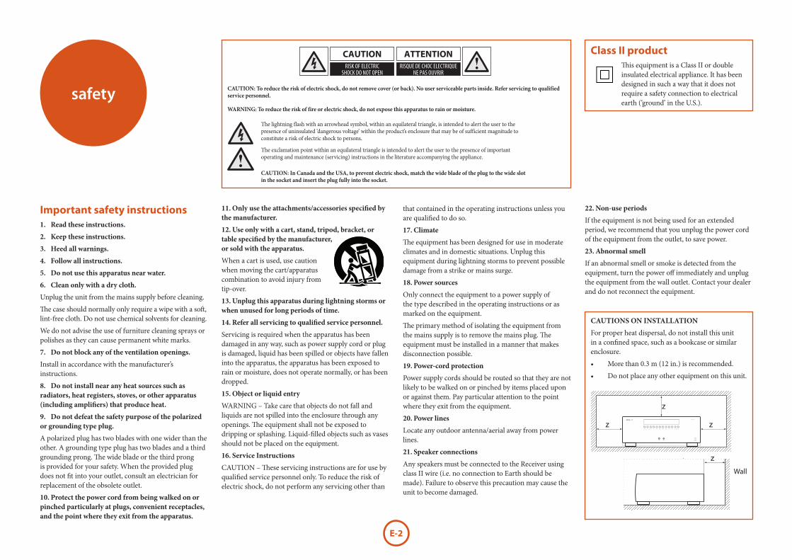
CAUTIONS ON INSTALLATION
For proper heat dispersal, do not install this unit in a confined space, such as a bookcase or similar enclosure.
• More than 0.3 m (12 in.) is recommended.
• Do not place any other equipment on this unit.
safety
Important safety instructions1. Read these instructions.
2. Keep these instructions.
3. Heed all warnings.
4. Follow all instructions.
5. Do not use this apparatus near water.
6. Clean only with a dry cloth.
Unplug the unit from the mains supply before cleaning.
The case should normally only require a wipe with a soft, lint-free cloth. Do not use chemical solvents for cleaning.
We do not advise the use of furniture cleaning sprays or polishes as they can cause permanent white marks.
7. Do not block any of the ventilation openings.
Install in accordance with the manufacturer’s instructions.
8. Do not install near any heat sources such as radiators, heat registers, stoves, or other apparatus (including amplifiers) that produce heat.
9. Do not defeat the safety purpose of the polarized or grounding type plug.
A polarized plug has two blades with one wider than the other. A grounding type plug has two blades and a third grounding prong. The wide blade or the third prong is provided for your safety. When the provided plug does not fit into your outlet, consult an electrician for replacement of the obsolete outlet.
10. Protect the power cord from being walked on or pinched particularly at plugs, convenient receptacles, and the point where they exit from the apparatus.
11. Only use the attachments/accessories specified by the manufacturer.
12. Use only with a cart, stand, tripod, bracket, or table specified by the manufacturer, or sold with the apparatus.
When a cart is used, use caution when moving the cart/apparatus combination to avoid injury from tip-over.
13. Unplug this apparatus during lightning storms or when unused for long periods of time.
14. Refer all servicing to qualified service personnel.
Servicing is required when the apparatus has been damaged in any way, such as power supply cord or plug is damaged, liquid has been spilled or objects have fallen into the apparatus, the apparatus has been exposed to rain or moisture, does not operate normally, or has been dropped.
15. Object or liquid entry
WARNING – Take care that objects do not fall and liquids are not spilled into the enclosure through any openings. The equipment shall not be exposed to dripping or splashing. Liquid-filled objects such as vases should not be placed on the equipment.
16. Service Instructions
CAUTION – These servicing instructions are for use by qualified service personnel only. To reduce the risk of electric shock, do not perform any servicing other than
that contained in the operating instructions unless you are qualified to do so.
17. Climate
The equipment has been designed for use in moderate climates and in domestic situations. Unplug this equipment during lightning storms to prevent possible damage from a strike or mains surge.
18. Power sources
Only connect the equipment to a power supply of the type described in the operating instructions or as marked on the equipment.
The primary method of isolating the equipment from the mains supply is to remove the mains plug. The equipment must be installed in a manner that makes disconnection possible.
19. Power-cord protection
Power supply cords should be routed so that they are not likely to be walked on or pinched by items placed upon or against them. Pay particular attention to the point where they exit from the equipment.
20. Power lines
Locate any outdoor antenna/aerial away from power lines.
21. Speaker connections
Any speakers must be connected to the Receiver using class II wire (i.e. no connection to Earth should be made). Failure to observe this precaution may cause the unit to become damaged.
22. Non-use periods
If the equipment is not being used for an extended period, we recommend that you unplug the power cord of the equipment from the outlet, to save power.
23. Abnormal smell
If an abnormal smell or smoke is detected from the equipment, turn the power off immediately and unplug the equipment from the wall outlet. Contact your dealer and do not reconnect the equipment.
CAUTION: To reduce the risk of electric shock, do not remove cover (or back). No user serviceable parts inside. Refer servicing to qualified service personnel.
WARNING: To reduce the risk of fire or electric shock, do not expose this apparatus to rain or moisture.
The lightning flash with an arrowhead symbol, within an equilateral triangle, is intended to alert the user to the presence of uninsulated ‘dangerous voltage’ within the product’s enclosure that may be of sufficient magnitude to constitute a risk of electric shock to persons.
The exclamation point within an equilateral triangle is intended to alert the user to the presence of important operating and maintenance (servicing) instructions in the literature accompanying the appliance.
CAUTION: In Canada and the USA, to prevent electric shock, match the wide blade of the plug to the wide slot in the socket and insert the plug fully into the socket.
Class II productThis equipment is a Class II or double insulated electrical appliance. It has been designed in such a way that it does not require a safety connection to electrical earth (‘ground’ in the U.S.).
zz
z
Wall
z
Wall

E-3
Eng
lish
FCC INFORMATION (FOR US CUSTOMERS)
1. PRODUCT
This product complies with Part 15 of the FCC Rules. Operation is subject to the following two conditions: (1) This device may not cause harmful interference, and (2) this device must accept any interference received, including interference that may cause undesired operation.
2. IMPORTANT NOTICE: DO NOT MODIFY THIS PRODUCT
This product, when installed as indicated in the instructions contained in this manual, meets FCC requirements. Modification not expressly approved by ARCAM may void your authority, granted by the FCC, to use the product.
3. NOTE
This product has been tested and found to comply with the limits for a Class B digital device, persuant to Part 15 of the FCC Rules. These limits are designed to provide reasonable protection against harmful interference in a residential installation.
This product generates, uses and can radiate radio frequency energy and, if not installed and used in accordance with the instructions, may cause harmful interference to radio communications. However, there is no guarantee that interference will not occur in a particular installation. If this product does cause harmful interference to radio or television reception, which can be determined by turning the product OFF and ON, the user is encouraged to try to correct the interference by one or more of the following measures:• Reorient or relocate the receiving antenna.• Increase the separation between the equipment
and receiver.• Connect the product into an outlet on a circuit
different from that to which the receiver is connected.
• Consult the local retailer authorized to distribute this type of product or an experienced radio/TV technician for help.
SAFETY INFORMATION(FOR EUROPEAN CUSTOMERS)• Avoid high temperatures. Allow for sufficient
heat dispersion when installed in a rack.• Handle the power cord carefully. Hold the plug
when unplugging the cord.• Keep the unit free from moisture, water, and
dust.• Unplug the power cord when not using the unit
for long periods of time.• Do not obstruct the ventilation holes.• Do not let foreign objects into the unit.• Do not let insecticides, benzene, and thinner
come in contact with the unit. • Never disassemble or modify the unit in any way.• Ventilation should not be impeded by covering
the ventilation openings with items, such as newspapers, tablecloths or curtains.
• Naked flame sources such as lighted candles should not be placed on the unit.
• Observe and follow local regulations regarding battery disposal.
• Do not expose the unit to dripping or splashing fluids.
• Do not place objects filled with liquids, such as vases, on the unit.
• Do not handle the mains cord with wet hands.• When the switch is in the OFF position, the
equipment is not completely switched off from MAINS.
• The equipment shall be installed near the power supply so that the power supply is easily accessible.
A NOTE ABOUT RECYCLING:
This product’s packaging materials are recyclable and can be reused. Please dispose of any materials in accordance with the local recycling regulations.When discarding the unit, comply with local rules or regulations.
Batteries should never be thrown away or incinerated but disposed of in accordance with the local regulations concerning battery disposal.
This product and the supplied accessories, excluding the batteries, constitute the applicable product according to the WEEE directive.
CORRECT DISPOSAL OF THIS PRODUCT
These markings indicate that this product should not be disposed with other household waste throughout the EU.
To prevent possible harm to the environment or human health from uncontrolled waste disposal and to conserve material resources, this product should be recycled responsibly.
To dispose of your product, please use your local return and collection systems or contact the retailer where the product was purchased.

E-4
E-5
Eng
lish
welcome
Thank you and congratulations on purchasing your Arcam FMJ Receiver.
Arcam has been producing specialist audio products of remarkable quality for over three decades and the new Receivers are the latest in a long line of award winning Hi-Fi. The design of the FMJ range draws upon all of Arcam’s experience as one of the UK’s most respected audio companies, to produce Arcam’s best performing range of products yet – designed and built to give you years of viewing and listening enjoyment.
This handbook is intended to give you a detailed guide to using the Receiver. It starts by giving advice on installation, moves on to describe how to use the product and finishes with additional information on the more advanced features. Use the contents list shown on this page to guide you to the section of interest.
We hope that your FMJ receiver will give you years of trouble-free operation. In the unlikely event of any fault, or if you simply require further information about Arcam products, our network of dealers will be happy to help you. Further information can also be found on the Arcam website at www.arcam.co.uk.
The FMJ development team
Contentssafety ...........................................................E-2
welcome ......................................................E-5
before you begin… ..................................E-6
rear panel connectors ..............................E-9
audio/video connections ..................... E-10Connection guide ................................................ E-12
radio connectors .................................... E-13
other connectors .................................... E-14
speakers ................................................... E-15
operation ................................................. E-17
front panel operation ............................ E-19
remote control ........................................ E-20
essential setup ........................................ E-26
auto speaker setup ................................ E-27
setup menus ........................................... E-28
decoding modes .................................... E-32Dolby volume ........................................................ E-34Dolby atmos ........................................................... E-34
tuner operation ...................................... E-35
network/usb operation ........................ E-36
multi-room set up .................................. E-37
customising the remote ....................... E-38
trouble shooting ..................................... E-40
specifications .......................................... E-42
legal information ................................... E-47
product guarantee ................................ E-47
Professional Installation?It may be that the Receiver has been installed and set up as part of your Hi-Fi installation by a qualified Arcam dealer. In this case, you may wish to skip the sections of this handbook dealing with installation and setting up, and move directly to the sections dealing with using the unit. Use the Contents list to guide you to these sections.
DIY setup?The Receiver is a powerful and sophisticated piece of AV equipment. If you are setting the unit up yourself, it is recommended that you read this handbook thoroughly before beginning. For instance, correct speaker configuration and placement is a key to getting the most out of your Receiver and making sure that all the elements of your system work in harmony.
E-6
The Receiver designed to produce a level of performance that will truly bring music and movies to life.
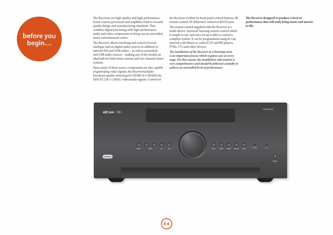
The Receivers are high-quality and high-performance home-cinema processors and amplifiers built to Arcam’s quality design and manufacturing standards. They combine digital processing with high-performance audio and video components to bring you an unrivalled home-entertainment centre.
The Receiver allows switching and control of seven analogue and six digital audio sources in addition to internal FM and DAB radios – as well as networked and USB audio sources – making any of the models an ideal hub for both home-cinema and two-channel stereo systems.
Since many of these source components are also capable of generating video signals, the Receiverincludes broadcast-quality switching for HDMI (6 x HDMI2.0a, HDCP2.2 & 1 x MHL) video/audio signals. Control of
the Receiver is either by front panel control buttons, IR remote control, IP (Ethernet) control or RS232 port.
The remote control supplied with the Receiver is a multi-device ‘universal’ learning remote control which is simple to use, and once set up is able to control a complete system. It can be programmed using its vast internal code library to control CD and BD players, PVRs, TVs and other devices.
The installation of the Receiver in a listening room is an important process which requires care at every stage. For this reason, the installation information is very comprehensive and should be followed carefully to achieve an unrivalled level of performance.
before you begin…
AVR850
E-7
Eng
lish
Placing the unit < Place the unit on a level, firm surface, avoiding direct sunlight and sources of heat or damp. < Do not place the Receiver on top of a power amplifier or other source of heat. < Do not place the amplifier in an enclosed space such as a bookcase or closed cabinet unless there is good provision for ventilation. The Receiver will run warm during normal operation. < Do not place any other component or item on top of the amplifier as this may obstruct airflow around the heat-sink, causing the amplifier to run hot. (The unit placed on top of the amplifier would become hot, too.) < Make sure the remote-control receiver on the front panel display is unobstructed, otherwise this will impair the use of the remote-control. If line-of-sight is impractical, a remote-control repeater can be used with the rear panel connector (see page E-14). < Do not place your record deck on top of this unit. Record decks are very sensitive to the noise generated by mains power supplies which will be heard as a background ‘hum’ if the record deck is too close.
PowerThe amplifier is supplied with a moulded mains plug already fitted to the lead. Check that the plug supplied fits your supply – should you require a new mains lead, please contact your Arcam dealer.
If your mains supply voltage or mains plug is different, please contact your Arcam dealer immediately.
The Receiver can be switched for operation between 220–240V (switch position 230V) and 110–120V (switch position 115V).
NOTE
Ensure that the Receiver is switched off and the power lead removed before changing the position of the voltage range switch.
Push the IEC plug end of the power cable into the socket on the back of the amplifier, making sure that it is pushed in firmly. Plug the other end of the cable into your mains socket and, if necessary, switch the socket on.
The Receiver can be turned on using the POWER switch on the front panel. While switched on, the front panel LED will glow green.
Standby powerThe Receiver can be switched into standby mode using the 2 button on the remote control. While in standby mode the front panel LED will glow red and power consumption is less than 0.5 Watts.
While in Standby mode, it may be possible to hear a slight residual hum coming from the mains transformer inside the amplifier. This is perfectly normal. However, if the unit is to be left unused for an extended period, we recommend that you disconnect it from the mains supply to save power.
Interconnect cablesWe recommend the use of high-quality screened cables that are designed for the particular application. Other cables will have different impedance characteristics that will degrade the performance of your system (for example, do not use cabling intended for video use to carry audio signals). All cables should be kept as short as is practically possible.
It is good practice when connecting your equipment to make sure that the mains power-supply cabling is kept as far away as possible from your audio cables. Failure to do so may result in unwanted noise in the audio signals.
For information on speaker cabling, please refer to the ‘Speakers’ section, beginning on page E-15.
Radio interferenceThe Receiver is an audio device containing microprocessors and other digital electronics. Each model has been designed to very high standards of electromagnetic compatibility.
This is a Class A product. In a domestic environment this product may cause radio interference, in which case the user may be required to take adequate measures.
If the Receiver causes interference to radio or television reception (which can be determined by switching the Receiver off and on), the following measures should be taken:
< Re-orient the receiving antenna or route the antenna cable of the affected receiver as far as possible from Receiver and its cabling. < Relocate the receiver with respect to the Receiver. < Connect the affected device and the Receiver to different mains outlets.
If the problem persists, please contact your Arcam dealer.
E-8
Dolby Volume
Manufactured under license from Dolby Laboratories. Dolby and the double-D symbol are trademarks of Dolby Laboratories.
AUDIO™
Dolby Atmos, Dolby Audio
Manufactured under license from Dolby Laboratories. Dolby, Dolby Atmos, Dolby Audio, and the double-D symbol are registered trademarks of Dolby Laboratories.
DTS-HD Master Audio™
For DTS patents, see http://patents.dts.com. Manufactured under license from DTS Licensing Limited. DTS, the Symbol, & DTS together in combination with the Symbol are trademarks of DTS, Inc. DTS and DTS-HD Master Audio are registered trademarks of DTS, Inc © DTS, Inc. All Rights Reserved.
DTS-HD™
For DTS patents, see http://patents.dts.com. Manufactured under license from DTS Licensing Limited. DTS, DTS-HD, the Symbol, & DTS and the Symbol together are registered trademarks of DTS, Inc. © DTS, Inc. All Rights Reserved.
DTS:X™
For DTS patents, see http://patents.dts.com. Manufactured under license from DTS Licensing Limited. DTS, the Symbol, DTS in combination with the symbol, DTS:X and the DTS:X logo are registered trademarks or trademarks of DTS, Inc. in the United States and/or other countries. © DTS, Inc. All Rights Reserved.
AAC/AAC Plus
aacPlus is a trademark of Coding Technologies. See http://codtech.vhost.noris.net for more information.
HDMI, the HDMI logo and High-Definition Multimedia Interface are trademarks or registered trademarks of HDMI Licensing LLC.
Licenses:
The Spotify software is subject to third party licenses found here:
https://developer.spotify.com/esdk-third-party-licenses
vTuner This product is protected by certain intellectual property rights of NEMS and BridgeCo. Use or distribution of such technology outside of this product is prohibited without a license from NEMS and BridgeCo or an authorized subsidiary.
MP3 MPEG Layer-3 audio decoding technology licensed from Fraunhofer IIS and Thomson multimedia.
Trademark acknowledgementsArcam is a registered trademark of A & R Cambridge Ltd.
FLAC FLAC Decoder Copyright © 2000, 2001, 2002, 2003, 2004, 2005, 2006, 2007, 2008 Josh Coalson
Redistribution and use in source and binary forms, with or without modification, are permitted provided that the following conditions are met:
- Redistributions of source code must retain the above copyright notice, this list of conditions and the following disclaimer.
- Redistributions in binary form must reproduce the above copyright notice, this list of conditions and the following disclaimer in the documentation and/or other materials provided with the distribution.
- Neither the name of the Xiph.org Foundation nor the names of its contributors may be used to endorse or promote products derived from this software without specific prior written permission.
THIS SOFTWARE IS PROVIDED BY THE COPYRIGHT HOLDERS AND CONTRIBUTORS ‘AS IS’ AND ANY EXPRESS OR IMPLIED WARRANTIES, INCLUDING, BUT NOT LIMITED TO, THE IMPLIED WARRANTIES OF MERCHANTABILITY AND FITNESS FOR A PARTICULAR PURPOSE ARE DISCLAIMED. IN NO EVENT SHALL THE FOUNDATION OR CONTRIBUTORS BE LIABLE FOR ANY DIRECT, INDIRECT, INCIDENTAL, SPECIAL, EXEMPLARY, OR CONSEQUENTIAL DAMAGES (INCLUDING, BUT NOT LIMITED TO, PROCUREMENT OF SUBSTITUTE GOODS OR SERVICES; LOSS OF USE, DATA, OR PROFITS; OR BUSINESS INTERRUPTION) HOWEVER CAUSED AND ON ANY THEORY OF LIABILITY, WHETHER IN CONTRACT, STRICT LIABILITY, OR TORT (INCLUDING NEGLIGENCE OR OTHERWISE) ARISING IN ANY WAY OUT OF THE USE OF THIS SOFTWARE, EVEN IF ADVISED OF THE POSSIBILITY OF SUCH DAMAGE.
E-9
Eng
lish
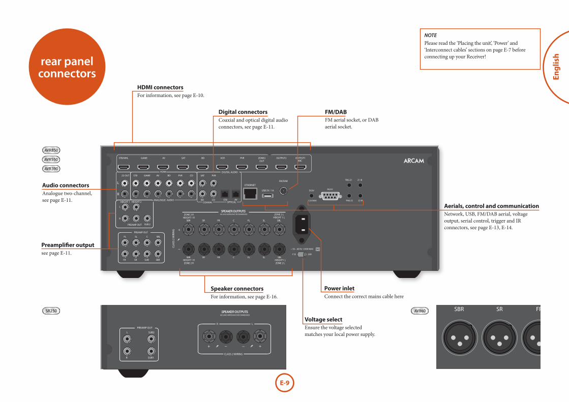
Network, USB, FM/DAB aerial, voltage output, serial control, trigger and IR connectors, see page E-13, E-14.
Coaxial and optical digital audio connectors, see page E-11.
Analogue two-channel, see page E-11.
NOTE
Please read the ‘Placing the unit’, ‘Power’ and ‘Interconnect cables’ sections on page E-7 before connecting up your Receiver!
Ensure the voltage selected matches your local power supply.
rear panel connectors
OUTPUT1ARC
SUB 2
R
L
HEIGHT 1 HEIGHT 2
PREAMP OUT
~ 50 – 60 Hz 1.5KW MAX
1.2A MAX TRIG Z2 Z2 IR
TRIG Z1
RS232DC6V
Z1 IR
ZONE2OUT
OUTPUT2AV
AV
ETHERNET
USB 5V / 1A
115 230
FM/DAB
PVR
PVR
VCRBDSAT
SBR SR FR C FL SL SBL
SBRSUBSRFR
CFL SL SBL
SBRHEIGHT 1 RZONE 2 R
HEIGHT1 LZONE 2 L
SR FR C FL SL SBL
STBZ2 OUT
ZONE 2 RHEIGHT 1 R
CLA
SS 2
WIR
ING
ZONE 2 LHEIGHT 1 L
8Ω LOAD IMPEDANCE RECOMMENDED
PVRSATBDAV
BD
CD
CD
GAME
STB/MHL
STB
GAME
SPEAKER OUTPUTS
OPTICALCOAXIAL
DIGITAL AUDIO
ANALOGUE AUDIO
HDMI
PREAMP OUT
For information, see page E-10.
For information, see page E-16.Power inlet
Digital connectors
Audio connectors
see page E-11.
Aerials, control and communication
FM aerial socket, or DAB aerial socket.
AVR850
AVR550
OUTPUT1ARC
CLASS 2 WIRING
R L
~ 50 – 60 Hz 1.5KW MAX
1.2A MAX TRIG Z2 Z2 IR
TRIG Z1
RS232DC6V
Z1 IR
ZONE2OUT
OUTPUT2AV
AV
ETHERNET
USB 5V / 1A
115 230
FM/DAB
PVR
PVR
VCRBDSAT
SUB1R
SUB2L
STBZ2 OUT
8Ω LOAD IMPEDANCE RECOMMENDED
PVRSATBDAV
BD
CD
CD
GAME
STB/MHL
STB
GAME
SPEAKER OUTPUTS
OPTICALCOAXIAL
DIGITAL AUDIO
ANALOGUE AUDIO
HDMI
PREAMP OUT
SR250
HDMI connectors
FM/DAB
Preamplifier output
Speaker connectorsConnect the correct mains cable here
Voltage select
AVR390
AV860
~ 50 – 60 Hz100W MAX
1.2A MAX TRIG Z2 Z2 IR
TRIG Z1
RS232DC6V
Z1 IR
OUTPUT1 OUTPUT2AV
AV
ETHERNET
USB 5V / 1A
115 230
FM/DAB
PVR
PVR
VCRBDSAT
AV BD
Y
Pb
Pr
SAT
STBZ2 OUTZ2
VIDEO OUTGAME PVR
STB BD
PVRSATBDAV
BD
CD
CD
GAME
STB
STB
GAME
OPTICALCOAXIAL
ARC
COMPOSITEDIGITAL AUDIO
ANALOGUE AUDIO
HDMI
COMPONENT
SBR SBL
SR SL
SUB C
FLFR
PREAMP OUT
SBR SR FR C SUB FL SL SBLZONE 2 R ZONE 2 L
BALANCED OUTPUTS
E-10
audio/video connections
Before connecting your Receiver to your source components and speakers, please read through the next few pages which will explain all the input and output connectivity that is available. The ‘Speakers’ section explains how to connect up your speakers to avoid damage to the amplifier and how to arrange your speakers for best performance.
GeneralThe inputs are named to make it easier to reference connected devices (e.g. ‘BD’ or ‘VCR’). They all have the same input circuit, so there is no reason why you should not connect a different device to any of the inputs. For example, if you had two BD players and the AV input was not being used, then the second BD player could be connected to the AV input.
When connecting a video source, its audio must be connected to the corresponding sockets. For example, if you had a satellite decoder plugged into a SAT video input, the audio must be connected to the SAT audio inputs!
Making connections < Take care to place cables as far from any power supply cabling as is practicable, to reduce hum and other noise problems.
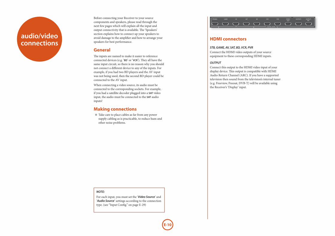
HDMI connectors
STB, GAME, AV, SAT, BD, VCR, PVR
Connect the HDMI video outputs of your source equipment to these corresponding HDMI inputs.
OUTPUT
Connect this output to the HDMI video input of your display device. This output is compatible with HDMI Audio Return Channel (ARC). If you have a supported television then sound from the television’s internal tuner (e.g. Freeview, Freesat, DVB-T) will be available using the Receiver’s ‘Display’ input.
NOTE:
For each input, you must set the ‘Video Source’ and ‘Audio Source’ settings according to the connection type. (see “Input Config.” on page E-29)
OUTPUT1ARC
SUB 2
R
L
HEIGHT 1 HEIGHT 2
PREAMP OUT
~ 50 – 60 Hz 1.5KW MAX
1.2A MAX TRIG Z2 Z2 IR
TRIG Z1
RS232DC6V
Z1 IR
ZONE2OUT
OUTPUT2AV
AV
ETHERNET
USB 5V / 1A
115 230
FM/DAB
PVR
PVR
VCRBDSAT
SBR SR FR C FL SL SBL
SBRSUBSRFR
CFL SL SBL
SBRHEIGHT 1 RZONE 2 R
HEIGHT1 LZONE 2 L
SR FR C FL SL SBL
STBZ2 OUT
ZONE 2 RHEIGHT 1 R
CLA
SS 2
WIR
ING
ZONE 2 LHEIGHT 1 L
8Ω LOAD IMPEDANCE RECOMMENDED
PVRSATBDAV
BD
CD
CD
GAME
STB/MHL
STB
GAME
SPEAKER OUTPUTS
OPTICALCOAXIAL
DIGITAL AUDIO
ANALOGUE AUDIO
HDMI
PREAMP OUT
E-11
Eng
lish
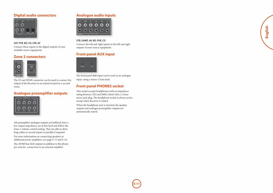
Digital audio connectorsOUTPUT1
ARC
SUB 2
R
L
HEIGHT 1 HEIGHT 2
PREAMP OUT
~ 50 – 60 Hz 1.5KW MAX
1.2A MAX TRIG Z2 Z2 IR
TRIG Z1
RS232DC6V
Z1 IR
ZONE2OUT
OUTPUT2AV
AV
ETHERNET
USB 5V / 1A
115 230
FM/DAB
PVR
PVR
VCRBDSAT
SBR SR FR C FL SL SBL
SBRSUBSRFR
CFL SL SBL
SBRHEIGHT 1 RZONE 2 R
HEIGHT1 LZONE 2 L
SR FR C FL SL SBL
STBZ2 OUT
ZONE 2 RHEIGHT 1 R
CLA
SS 2
WIR
ING
ZONE 2 LHEIGHT 1 L
8Ω LOAD IMPEDANCE RECOMMENDED
PVRSATBDAV
BD
CD
CD
GAME
STB/MHL
STB
GAME
SPEAKER OUTPUTS
OPTICALCOAXIAL
DIGITAL AUDIO
ANALOGUE AUDIO
HDMI
PREAMP OUT
SAT, PVR, BD, CD, STB, AV
Connect these inputs to the digital outputs of your available source equipment.
Zone 2 connectorsOUTPUT1
ARC
SUB 2
R
L
HEIGHT 1 HEIGHT 2
PREAMP OUT
~ 50 – 60 Hz 1.5KW MAX
1.2A MAX TRIG Z2 Z2 IR
TRIG Z1
RS232DC6V
Z1 IR
ZONE2OUT
OUTPUT2AV
AV
ETHERNET
USB 5V / 1A
115 230
FM/DAB
PVR
PVR
VCRBDSAT
SBR SR FR C FL SL SBL
SBRSUBSRFR
CFL SL SBL
SBRHEIGHT 1 RZONE 2 R
HEIGHT1 LZONE 2 L
SR FR C FL SL SBL
STBZ2 OUT
ZONE 2 RHEIGHT 1 R
CLA
SS 2
WIR
ING
ZONE 2 LHEIGHT 1 L
8Ω LOAD IMPEDANCE RECOMMENDED
PVRSATBDAV
BD
CD
CD
GAME
STB/MHL
STB
GAME
SPEAKER OUTPUTS
OPTICALCOAXIAL
DIGITAL AUDIO
ANALOGUE AUDIO
HDMI
PREAMP OUT
OUTPUT1ARC
SUB 2
R
L
HEIGHT 1 HEIGHT 2
PREAMP OUT
~ 50 – 60 Hz 1.5KW MAX
1.2A MAX TRIG Z2 Z2 IR
TRIG Z1
RS232DC6V
Z1 IR
ZONE2OUT
OUTPUT2AV
AV
ETHERNET
USB 5V / 1A
115 230
FM/DAB
PVR
PVR
VCRBDSAT
SBR SR FR C FL SL SBL
SBRSUBSRFR
CFL SL SBL
SBRHEIGHT 1 RZONE 2 R
HEIGHT1 LZONE 2 L
SR FR C FL SL SBL
STBZ2 OUT
ZONE 2 RHEIGHT 1 R
CLA
SS 2
WIR
ING
ZONE 2 LHEIGHT 1 L
8Ω LOAD IMPEDANCE RECOMMENDED
PVRSATBDAV
BD
CD
CD
GAME
STB/MHL
STB
GAME
SPEAKER OUTPUTS
OPTICALCOAXIAL
DIGITAL AUDIO
ANALOGUE AUDIO
HDMI
PREAMP OUT
The Z2 out HDMI connector can be used to connect the output of the Receiver to an system located in a second room.
Analogue preamplifier outputs
OUTPUT1ARC
SUB 2
R
L
HEIGHT 1 HEIGHT 2
PREAMP OUT
~ 50 – 60 Hz 1.5KW MAX
1.2A MAX TRIG Z2 Z2 IR
TRIG Z1
RS232DC6V
Z1 IR
ZONE2OUT
OUTPUT2AV
AV
ETHERNET
USB 5V / 1A
115 230
FM/DAB
PVR
PVR
VCRBDSAT
SBR SR FR C FL SL SBL
SBRSUBSRFR
CFL SL SBL
SBRHEIGHT 1 RZONE 2 R
HEIGHT1 LZONE 2 L
SR FR C FL SL SBL
STBZ2 OUT
ZONE 2 RHEIGHT 1 R
CLA
SS 2
WIR
ING
ZONE 2 LHEIGHT 1 L
8Ω LOAD IMPEDANCE RECOMMENDED
PVRSATBDAV
BD
CD
CD
GAME
STB/MHL
STB
GAME
SPEAKER OUTPUTS
OPTICALCOAXIAL
DIGITAL AUDIO
ANALOGUE AUDIO
HDMI
PREAMP OUT
All preamplifier analogue outputs are buffered, have a low output impedance, are at line level and follow the Zone 1 volume control setting. They are able to drive long cables or several inputs in parallel if required.
For more information on connecting speakers or additional power amplifiers, see page E-15 and E-16.
The AV860 has XLR outputs in addition to the phono pre-outs for connection to an external amplifier.
Analogue audio inputsOUTPUT1
ARC
SUB 2
R
L
HEIGHT 1 HEIGHT 2
PREAMP OUT
~ 50 – 60 Hz 1.5KW MAX
1.2A MAX TRIG Z2 Z2 IR
TRIG Z1
RS232DC6V
Z1 IR
ZONE2OUT
OUTPUT2AV
AV
ETHERNET
USB 5V / 1A
115 230
FM/DAB
PVR
PVR
VCRBDSAT
SBR SR FR C FL SL SBL
SBRSUBSRFR
CFL SL SBL
SBRHEIGHT 1 RZONE 2 R
HEIGHT1 LZONE 2 L
SR FR C FL SL SBL
STBZ2 OUT
ZONE 2 RHEIGHT 1 R
CLA
SS 2
WIR
ING
ZONE 2 LHEIGHT 1 L
8Ω LOAD IMPEDANCE RECOMMENDED
PVRSATBDAV
BD
CD
CD
GAME
STB/MHL
STB
GAME
SPEAKER OUTPUTS
OPTICALCOAXIAL
DIGITAL AUDIO
ANALOGUE AUDIO
HDMI
PREAMP OUT
STB, GAME, AV, BD, PVR, CD
Connect the left and right inputs to the left and right outputs of your source equipment.
Front panel AUX input
AVR850The front panel AUX input can be used as an analogue input, using a stereo 3.5mm lead.
Front panel PHONES socketThis socket accepts headphones with an impedance rating between 32Ω and 600Ω, fitted with a 3.5mm stereo jack plug. The headphone socket is always active, except when Receiver is muted.
When the headphone jack is inserted, the speaker outputs and analogue preamplifier outputs are automatically muted.
E-12
OUTPUT1ARC
SUB 2
R
L
HEIGHT 1 HEIGHT 2
PREAMP OUT
~ 50 – 60 Hz 1.5KW MAX
1.2A MAX TRIG Z2 Z2 IR
TRIG Z1
RS232DC6V
Z1 IR
ZONE2OUT
OUTPUT2AV
AV
ETHERNET
USB 5V / 1A
115 230
FM/DAB
PVR
PVR
VCRBDSAT
SBR SR FR C FL SL SBL
SBRSUBSRFR
CFL SL SBL
SBRHEIGHT 1 RZONE 2 R
HEIGHT1 LZONE 2 L
SR FR C FL SL SBL
STBZ2 OUT
ZONE 2 RHEIGHT 1 R
CLA
SS 2
WIR
ING
ZONE 2 LHEIGHT 1 L
8Ω LOAD IMPEDANCE RECOMMENDED
PVRSATBDAV
BD
CD
CD
GAME
STB/MHL
STB
GAME
SPEAKER OUTPUTS
OPTICALCOAXIAL
DIGITAL AUDIO
ANALOGUE AUDIO
HDMI
PREAMP OUT
BD/SATPr Pb Y
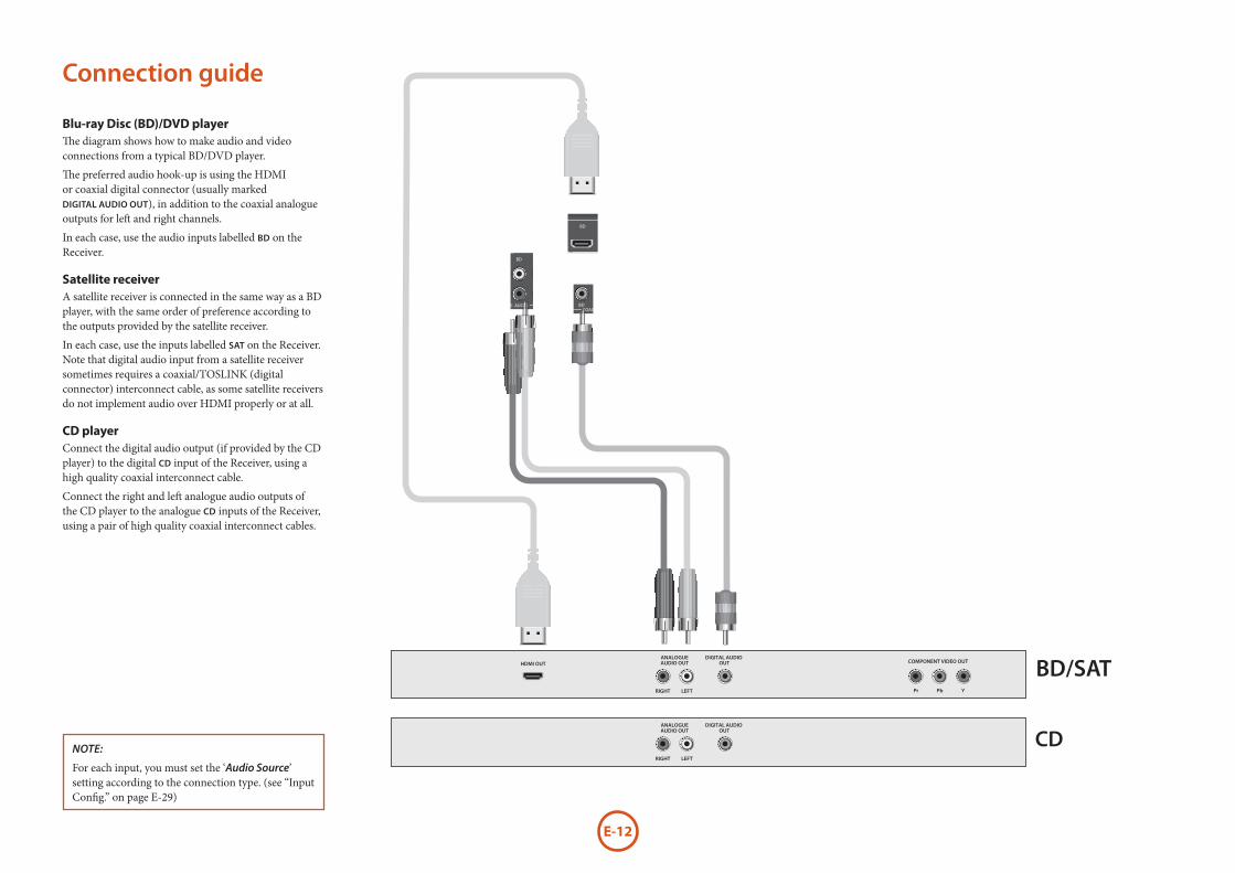
Connection guide
Blu-ray Disc (BD)/DVD playerThe diagram shows how to make audio and video connections from a typical BD/DVD player.
The preferred audio hook-up is using the HDMI or coaxial digital connector (usually marked DIGITAL AUDIO OUT), in addition to the coaxial analogue outputs for left and right channels.
In each case, use the audio inputs labelled BD on the Receiver.
Satellite receiverA satellite receiver is connected in the same way as a BD player, with the same order of preference according to the outputs provided by the satellite receiver.
In each case, use the inputs labelled SAT on the Receiver. Note that digital audio input from a satellite receiver sometimes requires a coaxial/TOSLINK (digital connector) interconnect cable, as some satellite receivers do not implement audio over HDMI properly or at all.
CD playerConnect the digital audio output (if provided by the CD player) to the digital CD input of the Receiver, using a high quality coaxial interconnect cable.
Connect the right and left analogue audio outputs of the CD player to the analogue CD inputs of the Receiver, using a pair of high quality coaxial interconnect cables.
NOTE:
For each input, you must set the ‘Audio Source’ setting according to the connection type. (see “Input Config.” on page E-29)

E-13
Eng
lish
DAB/FMOUTPUT1
ARC
SUB 2
R
L
HEIGHT 1 HEIGHT 2
PREAMP OUT
~ 50 – 60 Hz 1.5KW MAX
1.2A MAX TRIG Z2 Z2 IR
TRIG Z1
RS232DC6V
Z1 IR
ZONE2OUT
OUTPUT2AV
AV
ETHERNET
USB 5V / 1A
115 230
FM/DAB
PVR
PVR
VCRBDSAT
SBR SR FR C FL SL SBL
SBRSUBSRFR
CFL SL SBL
SBRHEIGHT 1 RZONE 2 R
HEIGHT1 LZONE 2 L
SR FR C FL SL SBL
STBZ2 OUT
ZONE 2 RHEIGHT 1 R
CLA
SS 2
WIR
ING
ZONE 2 LHEIGHT 1 L
8Ω LOAD IMPEDANCE RECOMMENDED
PVRSATBDAV
BD
CD
CD
GAME
STB/MHL
STB
GAME
SPEAKER OUTPUTS
OPTICALCOAXIAL
DIGITAL AUDIO
ANALOGUE AUDIO
HDMI
PREAMP OUT
In strong signal areas, the DAB/FM ‘T’ wire aerial supplied can be used with reasonable results. Mount the aerial as high up as possible on a wall.
In the UK the ‘T’-elements need to be positioned vertically for DAB reception since broadcasts are vertically polarised. In other localities, check with your Arcam dealer or try both horizontal and vertical positions for best reception.
Try each usable wall of the room to see which gives best reception and use tacks or adhesive tape to secure the aerial in a ‘T’ shape, but note
that no tacks should come into contact with the internal wire of the aerial.
When installed and receiving DAB/FM, check the signal strength by pressing the front panel or remote control’s INFO button until the signal quality indicator is displayed.
In weak signal areas, a high-gain, externally-mounted or roof-mounted aerial is desirable in order to receive the highest number of services.
In Band III transmission areas (such as the UK), use a multi-element Yagi aerial with the elements mounted vertically, as the transmissions are vertically polarised. If you are close to more than one transmitter, use an omnidirectional or folded dipole aerial.
If the DAB services in your area are transmitted on L-band, then ask your dealer for advice for the best aerial to use.
radio connectors
Aerial connectorsThe Receiver is fitted with an FM and a DAB/DAB+ receiver module. The type of aerial you need depends on your listening preferences and the local conditions.
Your Receiver is capable of superb radio reception, but only if it is receiving a good quality transmission signal.
Try the aerials supplied with your unit. If you are in a medium to strong signal area, these should be adequate for good reception. In areas with poor signal strength, you may require a roof or loft mounted aerial.
Contact your local Arcam dealer or aerial installation experts for advice about local reception conditions.

E-14
other connectors
Serial connector
RS232 serial connector
OUTPUT1ARC
SUB 2
R
L
HEIGHT 1 HEIGHT 2
PREAMP OUT
~ 50 – 60 Hz 1.5KW MAX
1.2A MAX TRIG Z2 Z2 IR
TRIG Z1
RS232DC6V
Z1 IR
ZONE2OUT
OUTPUT2AV
AV
ETHERNET
USB 5V / 1A
115 230
FM/DAB
PVR
PVR
VCRBDSAT
SBR SR FR C FL SL SBL
SBRSUBSRFR
CFL SL SBL
SBRHEIGHT 1 RZONE 2 R
HEIGHT1 LZONE 2 L
SR FR C FL SL SBL
STBZ2 OUT
ZONE 2 RHEIGHT 1 R
CLA
SS 2
WIR
ING
ZONE 2 LHEIGHT 1 L
8Ω LOAD IMPEDANCE RECOMMENDED
PVRSATBDAV
BD
CD
CD
GAME
STB/MHL
STB
GAME
SPEAKER OUTPUTS
OPTICALCOAXIAL
DIGITAL AUDIO
ANALOGUE AUDIO
HDMI
PREAMP OUT
The connector is used with control devices having an RS232 serial port (for example, Crestron and AMX touch-screen controllers).
Network connectorNetworking is a large subject and only the briefest guidelines are presented in this handbook. Please contact your Arcam dealer or specialist installer for more information about introducing the Receiver into your computer network.
For information on how to use the Receiver’s network features, the USB socket, and for a list of supported file types, refer to see page E-36.
OUTPUT1ARC
SUB 2
R
L
HEIGHT 1 HEIGHT 2
PREAMP OUT
~ 50 – 60 Hz 1.5KW MAX
1.2A MAX TRIG Z2 Z2 IR
TRIG Z1
RS232DC6V
Z1 IR
ZONE2OUT
OUTPUT2AV
AV
ETHERNET
USB 5V / 1A
115 230
FM/DAB
PVR
PVR
VCRBDSAT
SBR SR FR C FL SL SBL
SBRSUBSRFR
CFL SL SBL
SBRHEIGHT 1 RZONE 2 R
HEIGHT1 LZONE 2 L
SR FR C FL SL SBL
STBZ2 OUT
ZONE 2 RHEIGHT 1 R
CLA
SS 2
WIR
ING
ZONE 2 LHEIGHT 1 L
8Ω LOAD IMPEDANCE RECOMMENDED
PVRSATBDAV
BD
CD
CD
GAME
STB/MHL
STB
GAME
SPEAKER OUTPUTS
OPTICALCOAXIAL
DIGITAL AUDIO
ANALOGUE AUDIO
HDMI
PREAMP OUT
EthernetIf an Ethernet cable is connected, the Receiver will automatically attempt to connect to your network.
You should use CAT5 cable plugged into the RJ45 socket labelled ETHERNET on the rear panel.
If your network uses static IP addressing rather than DHCP, you will need to provide IP address, gateway and DNS; see page E-31 for information on setting up the network.
USB connectorThe Receiver can play files stored on a USB mass storage device, typically a pen drive, but any USB device that complies with the ‘mass storage device‘ class is compatible.
The Receiver only supports the direct connection of USB devices and will not support devices connected through a hub. If regular access to the USB socket is required, you may find it convenient to use a USB extension lead; see page E-36 for details of supported file types.
Trigger connectorsOUTPUT1
ARC
SUB 2
R
L
HEIGHT 1 HEIGHT 2
PREAMP OUT
~ 50 – 60 Hz 1.5KW MAX
1.2A MAX TRIG Z2 Z2 IR
TRIG Z1
RS232DC6V
Z1 IR
ZONE2OUT
OUTPUT2AV
AV
ETHERNET
USB 5V / 1A
115 230
FM/DAB
PVR
PVR
VCRBDSAT
SBR SR FR C FL SL SBL
SBRSUBSRFR
CFL SL SBL
SBRHEIGHT 1 RZONE 2 R
HEIGHT1 LZONE 2 L
SR FR C FL SL SBL
STBZ2 OUT
ZONE 2 RHEIGHT 1 R
CLA
SS 2
WIR
ING
ZONE 2 LHEIGHT 1 L
8Ω LOAD IMPEDANCE RECOMMENDED
PVRSATBDAV
BD
CD
CD
GAME
STB/MHL
STB
GAME
SPEAKER OUTPUTS
OPTICALCOAXIAL
DIGITAL AUDIO
ANALOGUE AUDIO
HDMI
PREAMP OUT
tip: Trigger output
sleeve: Ground
The trigger connectors (TRIG Z1 and TRIG Z2) provide an electrical signal whenever the Receiver is switched on and the relevant zone enabled.
The trigger signal can be used to switch on and off compatible pieces of home entertainment equipment, for example, you could set up a trigger to turn on your television and BD player whenever the Receiver was switched on.
There are two trigger output sockets on the Receiver, each capable of outputting a 12V, 70mA switching signal. The socket is designed for mono 3.5mm jacks: tip is the trigger output, sleeve is ground.
TRIG Z1
Use for remotely turning on and off power amps or source equipment for Zone 1. On = 12V, Off = 0V.
TRIG Z2
Use for remotely turning on and off power amps or source equipment for Zone 2. On = 12V, Off = 0V.
Infrared (IR) connectorsOUTPUT1
ARC
SUB 2
R
L
HEIGHT 1 HEIGHT 2
PREAMP OUT
~ 50 – 60 Hz 1.5KW MAX
1.2A MAX TRIG Z2 Z2 IR
TRIG Z1
RS232DC6V
Z1 IR
ZONE2OUT
OUTPUT2AV
AV
ETHERNET
USB 5V / 1A
115 230
FM/DAB
PVR
PVR
VCRBDSAT
SBR SR FR C FL SL SBL
SBRSUBSRFR
CFL SL SBL
SBRHEIGHT 1 RZONE 2 R
HEIGHT1 LZONE 2 L
SR FR C FL SL SBL
STBZ2 OUT
ZONE 2 RHEIGHT 1 R
CLA
SS 2
WIR
ING
ZONE 2 LHEIGHT 1 L
8Ω LOAD IMPEDANCE RECOMMENDED
PVRSATBDAV
BD
CD
CD
GAME
STB/MHL
STB
GAME
SPEAKER OUTPUTS
OPTICALCOAXIAL
DIGITAL AUDIO
ANALOGUE AUDIO
HDMI
PREAMP OUT
tip: Modulated signal
sleeve: Ground
The infrared inputs (Z1 IR and Z2 IR) allow the connection of external IR receivers, either when the Receiver front panel IR receiver is fully or partially obstructed or to allow the use of a remote control in Zone 2.
There are two IR inputs on the Receiver, each designed for stereo or mono 3.5mm jacks. Tip is the modulated signal, sleeve is ground.
Z1 IR
This input is intended for use with a local IR receiver when the front panel of the Receiver is blocked.
Z2 IR
This input is intended for use with an IR receiver in Zone 2 to allow remote control of Receiver from a second room.
NOTESockets referring to ‘Z2’ relate to connections used in multi-room installation. For more information on these connectors see page E-37.
A supplier of infra-red receivers and emitter accessories and systems is Xantech. See www.xantech.com for more information, or ask your Arcam dealer.
NOTE
The IR inputs on the Receiver are designed for modulated signals. If the external IR receiver demodulates the IR signal, it will not work. Also the unit does not provide power for external receivers on the IR jack, therefore an external power source will be required.
6V output
OUTPUT1ARC
SUB 2
R
L
HEIGHT 1 HEIGHT 2
PREAMP OUT
~ 50 – 60 Hz 1.5KW MAX
1.2A MAX TRIG Z2 Z2 IR
TRIG Z1
RS232DC6V
Z1 IR
ZONE2OUT
OUTPUT2AV
AV
ETHERNET
USB 5V / 1A
115 230
FM/DAB
PVR
PVR
VCRBDSAT
SBR SR FR C FL SL SBL
SBRSUBSRFR
CFL SL SBL
SBRHEIGHT 1 RZONE 2 R
HEIGHT1 LZONE 2 L
SR FR C FL SL SBL
STBZ2 OUT
ZONE 2 RHEIGHT 1 R
CLA
SS 2
WIR
ING
ZONE 2 LHEIGHT 1 L
8Ω LOAD IMPEDANCE RECOMMENDED
PVRSATBDAV
BD
CD
CD
GAME
STB/MHL
STB
GAME
SPEAKER OUTPUTS
OPTICALCOAXIAL
DIGITAL AUDIO
ANALOGUE AUDIO
HDMI
PREAMP OUT This provides a 6V DC power connection for Arcam rSeries products.
E-15
Eng
lish
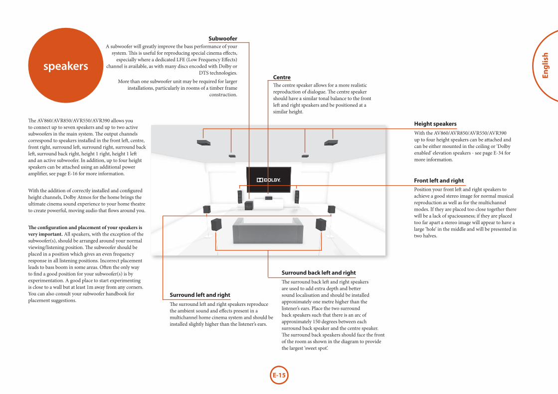
The surround left and right speakers reproduce the ambient sound and effects present in a multichannel home cinema system and should be installed slightly higher than the listener’s ears.
The surround back left and right speakers are used to add extra depth and better sound localisation and should be installed approximately one metre higher than the listener’s ears. Place the two surround back speakers such that there is an arc of approximately 150 degrees between each surround back speaker and the centre speaker. The surround back speakers should face the front of the room as shown in the diagram to provide the largest ‘sweet spot’.
Position your front left and right speakers to achieve a good stereo image for normal musical reproduction as well as for the multichannel modes. If they are placed too close together there will be a lack of spaciousness; if they are placed too far apart a stereo image will appear to have a large ‘hole’ in the middle and will be presented in two halves.
The centre speaker allows for a more realistic reproduction of dialogue. The centre speaker should have a similar tonal balance to the front left and right speakers and be positioned at a similar height.
A subwoofer will greatly improve the bass performance of your system. This is useful for reproducing special cinema effects,
especially where a dedicated LFE (Low Frequency Effects) channel is available, as with many discs encoded with Dolby or
DTS technologies.
More than one subwoofer unit may be required for larger installations, particularly in rooms of a timber frame
construction.
speakers
The AV860/AVR850/AVR550/AVR390 allows you to connect up to seven speakers and up to two active subwoofers in the main system. The output channels correspond to speakers installed in the front left, centre, front right, surround left, surround right, surround back left, surround back right, height 1 right, height 1 left and an active subwoofer. In addition, up to four height speakers can be attached using an additional power amplifier, see page E-16 for more information.
With the addition of correctly installed and configured height channels, Dolby Atmos for the home brings the ultimate cinema sound experience to your home theatre to create powerful, moving audio that flows around you.
The configuration and placement of your speakers is very important. All speakers, with the exception of the subwoofer(s), should be arranged around your normal viewing/listening position. The subwoofer should be placed in a position which gives an even frequency response in all listening positions. Incorrect placement leads to bass boom in some areas. Often the only way to find a good position for your subwoofer(s) is by experimentation. A good place to start experimenting is close to a wall but at least 1m away from any corners. You can also consult your subwoofer handbook for placement suggestions.
Front left and right
Centre
Surround left and right
Surround back left and right
Subwoofer
Height speakers
With the AV860/AVR850/AVR550/AVR390 up to four height speakers can be attached and can be either mounted in the ceiling or ‘Dolby enabled’ elevation speakers - see page E-34 for more information.

E-16
Connecting speakersTo connect each of the speakers, unscrew the corresponding terminals on the back of the Receiver, insert the speaker wires through the hole in each post and screw the terminals back up. Make sure that the red (positive/+) terminal of the speaker is connected to the red (positive/+) terminal on the back panel, and the black (negative/–) terminal of the speaker is connected to the black (negative/–) terminal on the back panel.
OUTPUT1ARC
SUB 2
R
L
HEIGHT 1 HEIGHT 2
PREAMP OUT
~ 50 – 60 Hz 1.5KW MAX
1.2A MAX TRIG Z2 Z2 IR
TRIG Z1
RS232DC6V
Z1 IR
ZONE2OUT
OUTPUT2AV
AV
ETHERNET
USB 5V / 1A
115 230
FM/DAB
PVR
PVR
VCRBDSAT
SBR SR FR C FL SL SBL
SBRSUBSRFR
CFL SL SBL
SBRHEIGHT 1 RZONE 2 R
HEIGHT1 LZONE 2 L
SR FR C FL SL SBL
STBZ2 OUT
ZONE 2 RHEIGHT 1 R
CLA
SS 2
WIR
ING
ZONE 2 LHEIGHT 1 L
8Ω LOAD IMPEDANCE RECOMMENDED
PVRSATBDAV
BD
CD
CD
GAME
STB/MHL
STB
GAME
SPEAKER OUTPUTS
OPTICALCOAXIAL
DIGITAL AUDIO
ANALOGUE AUDIO
HDMI
PREAMP OUT
It is important that no stray strands of wire from these connections are allowed to touch another cable or the product casing. Failure to ensure this can cause a short circuit and damage your Receiver.Do not over-tighten the loudspeaker terminals, or use a wrench, pliers, etc., as this could damage the terminals and this would not be covered under the product’s warranty.
Speaker cablesThe speakers should be connected to the amplifier using good-quality, high-purity, low impedance copper cables. Cheap speaker cables should be avoided – they are a false economy and can significantly degrade the sound quality.
The cable runs to the speakers should be as short as practicable. Connections to the speaker terminals should always be finger tight, whether using bare wires or spade connectors.
FLFRSBR SBL
Link MUSTbe removedLink MUST
be removed
Bi-amping the Front Left & Front Right speakersBi-amping is the use of two amplifier channels per speaker. Bi-amping can provide better sound quality than conventional single wiring. If you do not have Surround Back speakers (i.e. you have a 5.1 surround system, not a 7.1 system) then you can use the spare Surround Back speaker outputs to bi-amplify the front left and right speakers, if your speakers support bi-amping. The spare channels can alternatively be used to power stereo speakers in another room (Zone 2).
Speakers that support bi-amping have two sets of +/- terminals per speaker, usually linked together by metal strips. These metal strips MUST be removed when bi-amping; failure to remove them will result in damage to the amplifier that is not covered under warranty.
To bi-amp the front left and right speakers, remove the metal strips from the speaker terminals. Connect the woofer or LF terminals to the FL and FR terminals on the Receiver. Connect the tweeter or HF terminals to the SBL and SBR terminals on the Receiver. Finally, navigate to the Setup Menu ‘Spkr Types’ and set the ‘Use Channels 6+7 for’ menu option to ‘BiAmp L+R’; see page E-26.
Using external power amplifiersThe internal power amplifier of the Receiver (SR250 L, R, Sub only) can be supplemented or replaced with external power amplification, such as the Arcam P49 (recommended gain 31dB). Connect the PREAMP OUT sockets to your power amplifier inputs:
OUTPUT1ARC
SUB 2
R
L
HEIGHT 1 HEIGHT 2
PREAMP OUT
~ 50 – 60 Hz 1.5KW MAX
1.2A MAX TRIG Z2 Z2 IR
TRIG Z1
RS232DC6V
Z1 IR
ZONE2OUT
OUTPUT2AV
AV
ETHERNET
USB 5V / 1A
115 230
FM/DAB
PVR
PVR
VCRBDSAT
SBR SR FR C FL SL SBL
SBRSUBSRFR
CFL SL SBL
SBRHEIGHT 1 RZONE 2 R
HEIGHT1 LZONE 2 L
SR FR C FL SL SBL
STBZ2 OUT
ZONE 2 RHEIGHT 1 R
CLA
SS 2
WIR
ING
ZONE 2 LHEIGHT 1 L
8Ω LOAD IMPEDANCE RECOMMENDED
PVRSATBDAV
BD
CD
CD
GAME
STB/MHL
STB
GAME
SPEAKER OUTPUTS
OPTICALCOAXIAL
DIGITAL AUDIO
ANALOGUE AUDIO
HDMI
PREAMP OUT
FL, FR
Connect these to the equivalent Right and Left front channels of your power amplifier. For the SR250, only this and the sub outputs are available
C
Connect these to the Centre front channel of your power amplifier.
SUB
Subwoofer outputs. Connect this to the input of your active subwoofer(s), if present. For the SR250, only this and the FL, FLR outputs are available
SR, SL
Surround Right and Surround Left outputs. Connect these to the Surround Right and Left power amplifier inputs.
SBR, SBL
Surround Back Right and Surround Back Left outputs (only used in 7.1 channel systems). Connect these to the Surround Back Right and Surround Back Left power amplifier inputs.
Height 1, Height 2
Height 1 and Height 2. Connect these to the Height 1 and/or Height 2 power amplifier inputs.
All preamplifier analogue outputs are buffered, have a low output impedance and are at line level. They are able to drive long cables or several inputs in parallel if required.
Connecting subwoofers
OUTPUT1ARC
SUB 2
R
L
HEIGHT 1 HEIGHT 2
PREAMP OUT
~ 50 – 60 Hz 1.5KW MAX
1.2A MAX TRIG Z2 Z2 IR
TRIG Z1
RS232DC6V
Z1 IR
ZONE2OUT
OUTPUT2AV
AV
ETHERNET
USB 5V / 1A
115 230
FM/DAB
PVR
PVR
VCRBDSAT
SBR SR FR C FL SL SBL
SBRSUBSRFR
CFL SL SBL
SBRHEIGHT 1 RZONE 2 R
HEIGHT1 LZONE 2 L
SR FR C FL SL SBL
STBZ2 OUT
ZONE 2 RHEIGHT 1 R
CLA
SS 2
WIR
ING
ZONE 2 LHEIGHT 1 L
8Ω LOAD IMPEDANCE RECOMMENDED
PVRSATBDAV
BD
CD
CD
GAME
STB/MHL
STB
GAME
SPEAKER OUTPUTS
OPTICALCOAXIAL
DIGITAL AUDIO
ANALOGUE AUDIO
HDMI
PREAMP OUT
The Receiver also allows up to two active subwoofer to be connected to the SUB outputs. Refer to your subwoofer handbook for the correct setting up and connection procedure for your particular subwoofer(s).
Link MUST be removed
Link MUST be removed

E-17
Eng
lish
Operating your ReceiverFor information display we recommend you use the OSD (On-Screen Display) on your display device whenever possible.
Switching onPress the front panel power button in. The power LED will glow green, the front display shows the word
‘ARCAM’. When initialisation is complete, the display shows the volume setting and the name of the selected input.
Please wait until the unit has finished initialising before operating the Receiver. It is recommended that if the unit is switched off, you should wait at least 10 seconds before switching the unit back on.
StandbyThe Receiver has a standby mode which can be entered by pressing STANDBY on the remote control. When in standby mode, the display is blank and the POWER LED glows red.
If the unit is to be left unused for an extended period, we recommend that you disconnect it from the mains supply to save power.
To switch on from standbyPress the STANDBY button on the remote control, any key on the front panel (other than the power button) or rotate the volume knob.
Front panel displayThe Receiver is ready for use after about four seconds.
B D 37
The display window shows the currently selected source and the last selected information view setting (this information line can be changed using the INFO button).
The current volume setting for Zone 1 (37.0dB in the above example) is displayed on the front panel. The volume setting for Zone 2 is displayed temporarily whenever it is adjusted.
Selecting a sourceTo select a particular source, press the –INPUT or INPUT+ buttons until that source is shown on the front panel display, or (if available) press the corresponding
operation
source button on the remote. The following sources are available:
STB Set Top Box inputGAME Game console input
AV Audio-Visual inputSAT Satellite inputBD Blu-ray Disc/DVD player input
VCR Video Cassette Recorder input
PVR Personal Video Recorder inputCD Compact Disc player inputFM Internal tuner input
DAB Internal tuner input (this source is market dependent and may not be available on your Receiver)
NET Ethernet inputUSB External USB solid-state device (e.g.
pen drive, iPad) inputAUX Auxiliary (front panel) input
DISPLAY The Audio Return Channel (ARC) from a compliant display. Use this with a compliant television using internal TV tuners.
Most audio inputs have both analogue and digital connections. You must specify the type of connection used for each input using the ‘Audio Source’ option in the ‘Input Config.’ menu, see page E-29. Note that an incorrect setting will result in no sound — the default is HDMI audio. If you are not using HDMI audio then this setting must be changed.
The processing mode and Stereo Direct functions are remembered and recalled for each individual input.
Stereo DirectTo listen to a pure analogue stereo input, press the DIRECT button. The Stereo Direct mode automatically bypasses all processing and any surround functions. In direct mode, digital processing is shut down to improve the sound quality and reduces digital noise with the Receiver to an absolute minimum.
Note: when Stereo Direct mode is selected, no digital output is available and no bass management is performed, meaning that bass signals will not be redirected to a subwoofer.
Volume controlIt is important to realise that the level of the volume indicator is not an accurate indication of the power delivered to your loudspeakers. The Receiver often delivers its full output power long before the volume control reaches its maximum position, particularly when listening to heavily recorded music. In comparison, some movie sound tracks can appear very quiet, as many directors like to keep maximum levels in reserve for special effects sequences.
HeadphonesTo use headphones with the Receiver, plug the headphones into the PHONES socket in the centre of the front panel.
When headphones are plugged into the front panel PHONES socket, the outputs for Zone 1 are muted and the audio will be down-mixed to two channels (2.0). The two-channel down-mix is required so that the centre channel and surround information can be heard via the headphones.

E-18
Using Zone 2Zone 2 provides the option for the occupants of the master bedroom, conservatory, kitchen, etc. to view or listen to a different source at a different volume level from the main zone (Zone 1).
Source selection and volume control for Zone 2 is achieved:
< by using an IR receiver in Zone 2 (see “Zone 2 control connections” on page E-37), or < by switching over to Zone 2 control by pressing the front panel zone button, or < by pressing AMP + OK on the remote control.
The front panel VFD display indicates that control has been switched to Zone 2.
STANDBY Z2 5 0
To turn on Zone 2, with the remote, AMP + OK then press the standby power button on the remote control or press ZONE button on the front panel and then release it to select zone 2, then press and hold the ZONE button on the front panel to turn on Zone 2. Press a source select button to select a different source to Zone 1.
FOLLOW Z 1 Z2 5 0
Note that Zone 2 control from within Zone 1 will pass automatically back to Zone 1 control after a few seconds of inactivity.
Zone 2 can also be controlled using a third-party programmable remote control or a home automation system. Please contact your dealer or installer for further details.
Extended front panel menuPressing the MENU key on the front panel and holding it for longer than four seconds will bring up the Extended Menu, allowing you to perform the following:
Restore to factory defaultsThis option allows you to restore all settings on your Receiver to the defaults that it left the factory with.
Change remote codeThe default RC5 system code the Receiver responds to is 16. If required, for example due to another device in your system also using this RC5 system code, it can be changed to 19.
Restore secure backupThis option allows you to restore all settings to their state as saved using the ‘Store secure backup’ feature. This option is useful if settings are accidentally changed. It also allows the unit to be returned to the saved state following a firmware update.
Store secure backupThis option allows you to save all the Receiver settings to a secure area of memory. The settings can be retrieved using the Restore option above.
– Enter PIN
Enter the secure backup PIN using the ', < , > and , keys on the remote control (do not use the numeric keypad). The default PIN is 0000.
– Change PIN
Allows the PIN to be changed to a number other than the default. Enter the current secure backup PIN using the ', < , > and , keys on the remote control (do not use the numeric keypad). The default PIN is 0000. After the current PIN has been entered correctly, enter a new PIN as prompted and again to confirm.
– EXIT
Cancel and return to the extended menu.
Updating firmware via USBThe firmware in your Receiver can be updated from a USB flash drive containing firmware update files.
You can download the latest firmware file, together with upgrading instructions, from the Arcam website (www.arcam.co.uk).

E-19
Eng
lish
Mutes all analogue audio outputs in the currently selected zone.
Switches the main power to the Receiver on and off.
Once the unit is switched off, it should be left for at least ten seconds before switching on again.
Auxiliary line level input.
This socket accepts headphones with an impedance rating between 32Ω and 600Ω, fitted with a 3.5mm stereo jack plug.
This switches the display brightness between off/dim/bright.
Selects between Zone 1 and Zone 2 control.
This indicates the status of the receiver and is green when the Receiver is powered on. Red indicates the unit is in Standby mode.
Used to enter selections made in the Setup menu.
Selects the information displayed on the lower left portion of the front panel.
Selects between Stereo and the available surround
modes for the current source.
Stereo Direct on/off. Provides a direct analogue path from the analogue inputs to the left and right front outputs. Switches off any surround processing modes and shuts down the DSP circuits for best stereo sound quality.
AVR850
Remote control receiver. This is positioned behind the display window, above the MENU button on the front panel. Ensure the receiver is in a clear line of sight from the remote control for operation. If this is not possible, use a separate sensor connected to the Z1 IR input on the rear panel.
front panel operation
Adjusts the analogue output volume in the selected zone (line out, speakers and headphones).
These buttons select the source connected to the corresponding
input (or internal input)
Unused sources can be prevented from being selected in the setup
menu by blanking the name in MENU > Input Config.
Selects the Setup menus on the on-screen display (OSD).
Info
Mode
Direct
Display
OKZone
Power/Standby LED
Phones
Aux
Power
Input
Menu
Volume
Mute
E-20
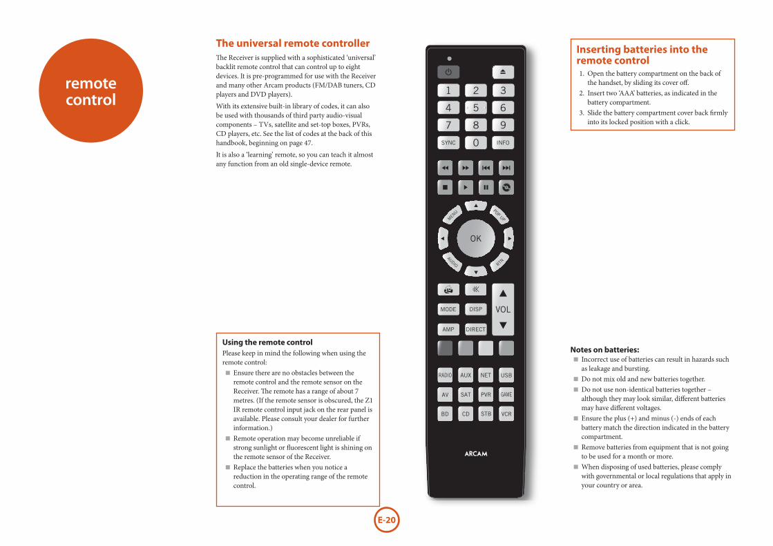
The universal remote controllerThe Receiver is supplied with a sophisticated ‘universal’ backlit remote control that can control up to eight devices. It is pre-programmed for use with the Receiver and many other Arcam products (FM/DAB tuners, CD players and DVD players).
With its extensive built-in library of codes, it can also be used with thousands of third party audio-visual components – TVs, satellite and set-top boxes, PVRs, CD players, etc. See the list of codes at the back of this handbook, beginning on page 47.
It is also a ‘learning’ remote, so you can teach it almost any function from an old single-device remote.
remote control
Using the remote controlPlease keep in mind the following when using the remote control:
< Ensure there are no obstacles between the remote control and the remote sensor on the Receiver. The remote has a range of about 7 metres. (If the remote sensor is obscured, the Z1 IR remote control input jack on the rear panel is available. Please consult your dealer for further information.) < Remote operation may become unreliable if strong sunlight or fluorescent light is shining on the remote sensor of the Receiver. < Replace the batteries when you notice a reduction in the operating range of the remote control.
Notes on batteries: < Incorrect use of batteries can result in hazards such as leakage and bursting. < Do not mix old and new batteries together. < Do not use non-identical batteries together – although they may look similar, different batteries may have different voltages. < Ensure the plus (+) and minus (-) ends of each battery match the direction indicated in the battery compartment. < Remove batteries from equipment that is not going to be used for a month or more. < When disposing of used batteries, please comply with governmental or local regulations that apply in your country or area.
Inserting batteries into the remote control1. Open the battery compartment on the back of
the handset, by sliding its cover off.2. Insert two ‘AAA’ batteries, as indicated in the
battery compartment.3. Slide the battery compartment cover back firmly
into its locked position with a click.
E-21
Eng
lish
The remote remains in the last selected Device Mode so it is not necessary to press a Device Mode key before every command key if all you are doing is playing or skipping tracks on a CD, for example.
Navigation keysThe Navigation keys steer the cursor in Setup menus or on-screen menus. They also replicate the navigation functions of original remotes supplied with other home entertainment
devices in your system. OK confirms a setting.
Volume controlBy default, the remote is set up so that the volume control and mute buttons always control the volume of the Receiver, regardless of which Device Mode the remote is currently set for. This is known as volume ‘punch through’.
For example, if you are listening to a CD, you will probably have the remote in CD Device Mode to control the CD player. You can use the volume controls on the remote directly to adjust the volume of the Receiver without first having to press AMP to put the remote into AMP Device Mode. The volume buttons ‘punch through’ the CD Device Mode on the remote to the AMP Device Mode.
Volume ‘punch through’ can be disabled individually for any Device Mode if desired.
Customising the remoteThe remote offers a Code Learning feature that allows you to copy up to 16 functions from an original remote control onto the remote keypad. For details of this, and other customisation features, see “customising the remote” on page E-38.
Useful information
BacklightA backlight comes on for eight seconds whenever a key is pressed. This helps you use the handset in subdued lighting conditions.
LED blinksShort blinks indicate a valid key press.Multiple short blinks convey information (such as a device code) or signal the beginning and successful completion of a programming sequence.
The symbol ‘*’ is used in the manual to indicate an LED blink.
Timeouts and unassigned keysTime out – After 30 seconds the remote exits the programming state and returns to normal operation.
Stuck key timeout – After any key is pressed continuously for 30 seconds, the remote stops sending IR transmission to conserve battery life. The remote remains off until all keys are released.
Unassigned keys – the remote ignores any unassigned key presses for a particular Device Mode and does not transmit IR.
Low voltage indicatorWhen the batteries are running down, the backlight flashes briefly whenever you press a button.
If this happens, fit two new AAA alkaline batteries as soon as possible.
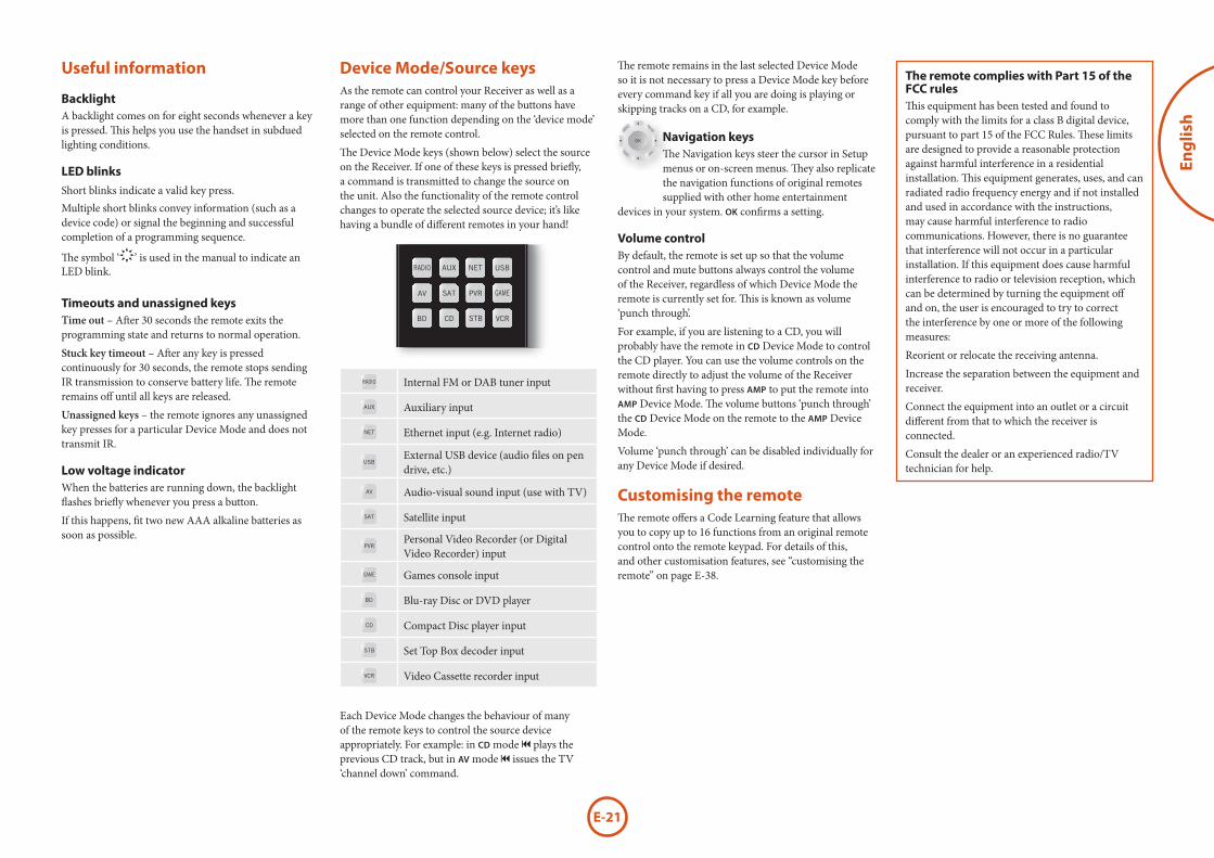
Device Mode/Source keysAs the remote can control your Receiver as well as a range of other equipment: many of the buttons have more than one function depending on the ‘device mode’ selected on the remote control.
The Device Mode keys (shown below) select the source on the Receiver. If one of these keys is pressed briefly, a command is transmitted to change the source on the unit. Also the functionality of the remote control changes to operate the selected source device; it’s like having a bundle of different remotes in your hand!
Internal FM or DAB tuner input
Auxiliary input
Ethernet input (e.g. Internet radio)
External USB device (audio files on pen drive, etc.)
Audio-visual sound input (use with TV)
Satellite input
Personal Video Recorder (or Digital Video Recorder) input
Games console input
Blu-ray Disc or DVD player
Compact Disc player input
Set Top Box decoder input
Video Cassette recorder input
Each Device Mode changes the behaviour of many of the remote keys to control the source device appropriately. For example: in CD mode 9 plays the previous CD track, but in AV mode 9 issues the TV ‘channel down’ command.
The remote complies with Part 15 of the FCC rulesThis equipment has been tested and found to comply with the limits for a class B digital device, pursuant to part 15 of the FCC Rules. These limits are designed to provide a reasonable protection against harmful interference in a residential installation. This equipment generates, uses, and can radiated radio frequency energy and if not installed and used in accordance with the instructions, may cause harmful interference to radio communications. However, there is no guarantee that interference will not occur in a particular installation. If this equipment does cause harmful interference to radio or television reception, which can be determined by turning the equipment off and on, the user is encouraged to try to correct the interference by one or more of the following measures:
Reorient or relocate the receiving antenna.
Increase the separation between the equipment and receiver.
Connect the equipment into an outlet or a circuit different from that to which the receiver is connected.
Consult the dealer or an experienced radio/TV technician for help.

E-22
AMP Device ModeThe AMP Device Mode button configures the remote to control the Receiver. Pressing this button does not affect the currently selected input on the Receiver.
The functionality of the remote is context sensitive for the internal sources and is described in the following table.
2 Single press – Toggles Receiver power between standby and on in the current zone (zone in which the command is received).
Press and hold – Forces all zones into standby, regardless of which zone the command was received in.
0......9 The number keys can be used for direct entry of numeric values
SYNC Sync. Delays may be introduced into the video signal by video processing which causes a mismatch between the audio and video timing. You will notice this by speech sound being out of synchronization with the lip movements in the video. To compensate for this, you can adjust the lip sync delay. Press the SYNC button and use the < and > navigation buttons. Press again to exit the lip sync trim menu.
INFO Info cycles through the information displayed on the lower left portion of the front panel display when on TUN, NET and USB inputs.
Brings up the DTS:X dialogue control adjustment.
MENU Displays the unit’s setup menu on the On Screen Display.
POP UP Toggles Dolby Volume on/off.AUDIO Toggles Dirac Live EQ on/off.
RTN Brings up a temporary subwoofer trim control. Use the < and > navigation buttons. Press RTN again to exit the sub trim control. As this is a temporary adjustment, the sub trim level is reset to the value set in the Speaker Levels menu when the unit is turned off or put into standby.
Toggles the mute function of the AVR.VOL Adjust amplifier volume.
MODE Cycles through the available surround and downmix modes.
DISP Cycles through the front panel display’s brightness options
AMP Resets remote to AMP mode.DIRECT Stereo direct on/off. Provides a direct
analogue path from the analogue inputs to the left and right front outputs. Switches off any surround processing modes and shuts down the DSP circuits for the best stereo sound quality.
Navigate the files and menus on the screen.
OK selects the highlighted file or enters the highlighted menu on the screen – equivalent to ‘Enter’ or ‘Select’ on some remote controls.
' Up< Left
> Right
, Down
AMP + ' Power on from standby
AMP + , Standby from Power on
AMP + OK select Zone 2RED Red button.
GREEN Green button.YELLOW Yellow button.
BLUE Blue button.RADIO Tuner input.
AUX Aux input.NET Network (NET) input.USB USB input.AV AV input.SAT SAT input.PVR PVR input.
GAME Game console input.BD BD input.CD CD input.
STB STB input.VCR VCR input.
USB commandsThe USB interface is selected by pressing USB in AMP Device Mode on the remote. When connected to a device storing music files connected by USB, the keys below are used to navigating music tracks.
Navigates the files on screen.
OK selects/plays the highlighted file.
9
:
Selects the previous/next track in the current playlist.
4; Pause and playback of the current track.
Stops playback..
Network commandsWhen using the network client, the keys below are used to navigate music files in AMP Device Mode.
Navigates the files on screen.
OK selects/plays the highlighted file.
9
:
Selects the previous/next track in the current playlist.
4; Pause and playback of the current track.
Stops playback..RED Adds the currently displayed radio station
to the favourites list when using the network client.
GREEN Removes the currently displayed radio station to the favourites list when using the network client.
Returns navigation to the top level of the network client menus (‘Home’)
E-23
Eng
lish
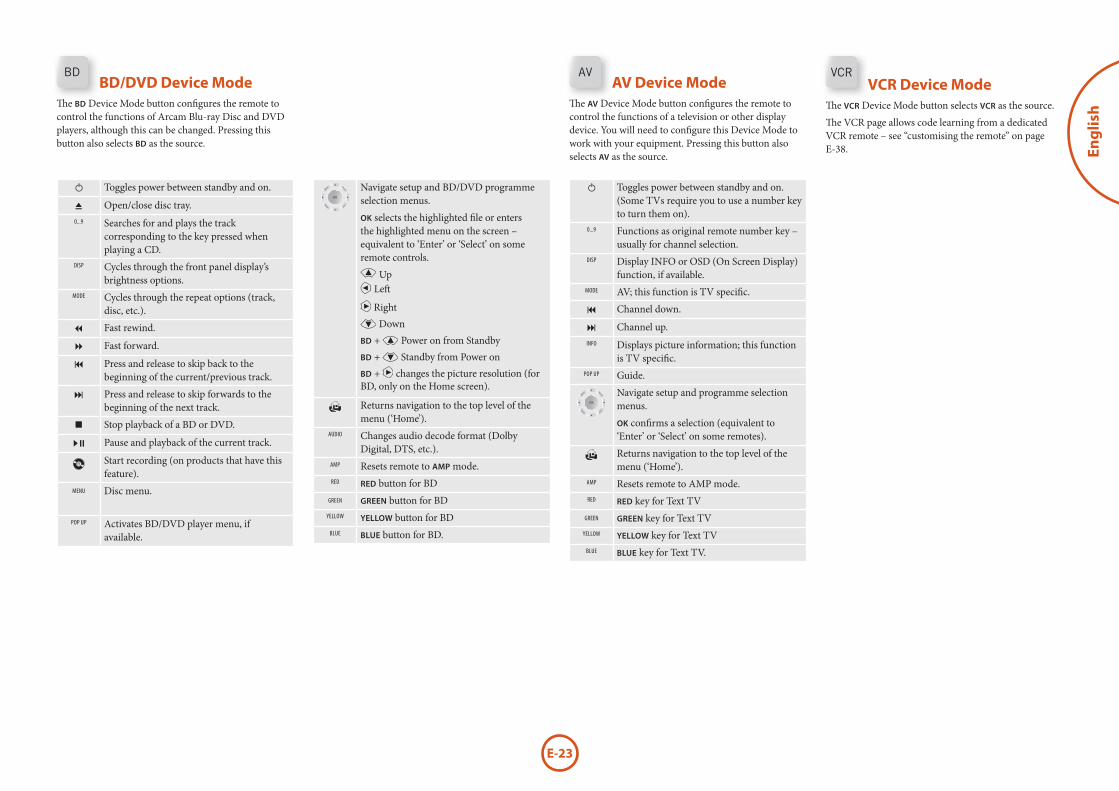
BD/DVD Device ModeThe BD Device Mode button configures the remote to control the functions of Arcam Blu-ray Disc and DVD players, although this can be changed. Pressing this button also selects BD as the source.
2 Toggles power between standby and on.
1 Open/close disc tray.0...9 Searches for and plays the track
corresponding to the key pressed when playing a CD.
DISP Cycles through the front panel display’s brightness options.
MODE Cycles through the repeat options (track, disc, etc.).
7 Fast rewind.
8 Fast forward.
9 Press and release to skip back to the beginning of the current/previous track.
: Press and release to skip forwards to the beginning of the next track.
Stop playback of a BD or DVD.
4; Pause and playback of the current track.
Start recording (on products that have this feature).
MENU Disc menu.
POP UP Activates BD/DVD player menu, if available.
Navigate setup and BD/DVD programme selection menus.
OK selects the highlighted file or enters the highlighted menu on the screen – equivalent to ‘Enter’ or ‘Select’ on some remote controls.
' Up< Left
> Right
, DownBD + ' Power on from StandbyBD + , Standby from Power onBD + > changes the picture resolution (for BD, only on the Home screen).
Returns navigation to the top level of the menu (‘Home’).
AUDIO Changes audio decode format (Dolby Digital, DTS, etc.).
AMP Resets remote to AMP mode.RED RED button for BD
GREEN GREEN button for BDYELLOW YELLOW button for BD
BLUE BLUE button for BD.
2 Toggles power between standby and on. (Some TVs require you to use a number key to turn them on).
0...9 Functions as original remote number key – usually for channel selection.
DISP Display INFO or OSD (On Screen Display) function, if available.
MODE AV; this function is TV specific.
9 Channel down.
: Channel up.INFO Displays picture information; this function
is TV specific.POP UP Guide.
Navigate setup and programme selection menus.
OK confirms a selection (equivalent to ‘Enter’ or ‘Select’ on some remotes).
Returns navigation to the top level of the menu (‘Home’).
AMP Resets remote to AMP mode.RED RED key for Text TV
GREEN GREEN key for Text TVYELLOW YELLOW key for Text TV
BLUE BLUE key for Text TV.
AV Device ModeThe AV Device Mode button configures the remote to control the functions of a television or other display device. You will need to configure this Device Mode to work with your equipment. Pressing this button also selects AV as the source.
VCR Device ModeThe VCR Device Mode button selects VCR as the source.
The VCR page allows code learning from a dedicated VCR remote – see “customising the remote” on page E-38.
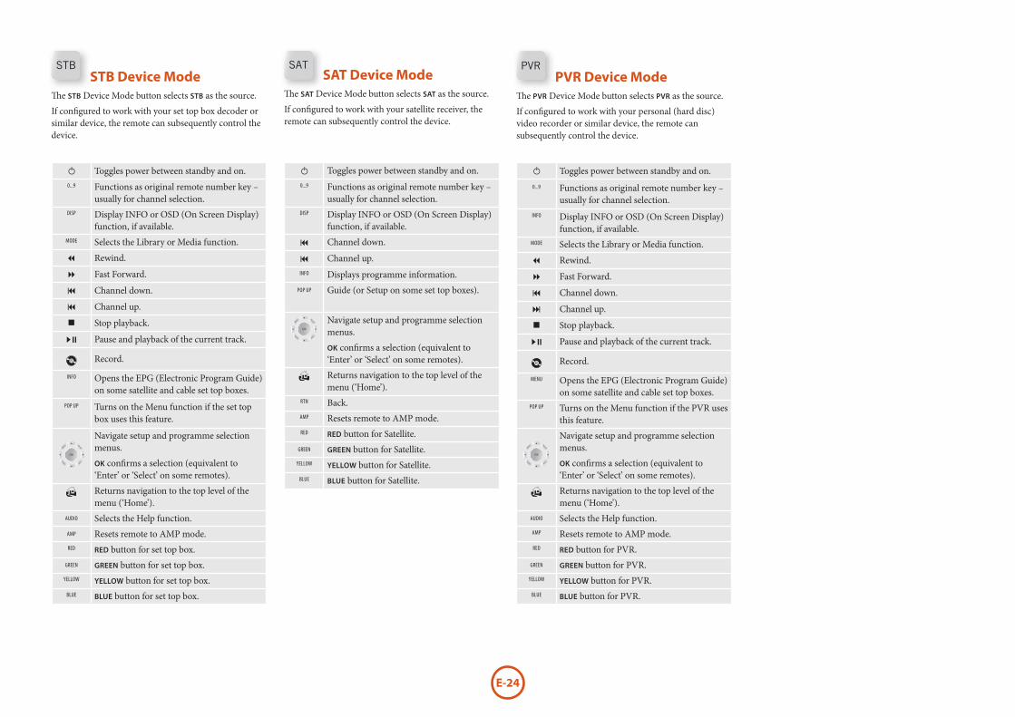
E-24
SAT Device ModeThe SAT Device Mode button selects SAT as the source.
If configured to work with your satellite receiver, the remote can subsequently control the device.
2 Toggles power between standby and on.0...9 Functions as original remote number key –
usually for channel selection.DISP Display INFO or OSD (On Screen Display)
function, if available.
9 Channel down.
9 Channel up.INFO Displays programme information.
POP UP Guide (or Setup on some set top boxes).
Navigate setup and programme selection menus.
OK confirms a selection (equivalent to ‘Enter’ or ‘Select’ on some remotes).
Returns navigation to the top level of the menu (‘Home’).
RTN Back.AMP Resets remote to AMP mode.RED RED button for Satellite.
GREEN GREEN button for Satellite.YELLOW YELLOW button for Satellite.
BLUE BLUE button for Satellite.
2 Toggles power between standby and on.0...9 Functions as original remote number key –
usually for channel selection.DISP Display INFO or OSD (On Screen Display)
function, if available.MODE Selects the Library or Media function.
7 Rewind.
8 Fast Forward.
9 Channel down.
9 Channel up.
Stop playback.
4; Pause and playback of the current track.
Record.
INFO Opens the EPG (Electronic Program Guide) on some satellite and cable set top boxes.
POP UP Turns on the Menu function if the set top box uses this feature.
Navigate setup and programme selection menus.
OK confirms a selection (equivalent to ‘Enter’ or ‘Select’ on some remotes).
Returns navigation to the top level of the menu (‘Home’).
AUDIO Selects the Help function.AMP Resets remote to AMP mode.RED RED button for set top box.
GREEN GREEN button for set top box.YELLOW YELLOW button for set top box.
BLUE BLUE button for set top box.
2 Toggles power between standby and on.0...9 Functions as original remote number key –
usually for channel selection.INFO Display INFO or OSD (On Screen Display)
function, if available.MODE Selects the Library or Media function.
7 Rewind.
8 Fast Forward.
9 Channel down.
: Channel up.
Stop playback.
4; Pause and playback of the current track.
Record.
MENU Opens the EPG (Electronic Program Guide) on some satellite and cable set top boxes.
POP UP Turns on the Menu function if the PVR uses this feature.
Navigate setup and programme selection menus.
OK confirms a selection (equivalent to ‘Enter’ or ‘Select’ on some remotes).
Returns navigation to the top level of the menu (‘Home’).
AUDIO Selects the Help function.AMP Resets remote to AMP mode.RED RED button for PVR.
GREEN GREEN button for PVR.YELLOW YELLOW button for PVR.
BLUE BLUE button for PVR.
STB Device ModeThe STB Device Mode button selects STB as the source.
If configured to work with your set top box decoder or similar device, the remote can subsequently control the device.
PVR Device ModeThe PVR Device Mode button selects PVR as the source.
If configured to work with your personal (hard disc) video recorder or similar device, the remote can subsequently control the device.
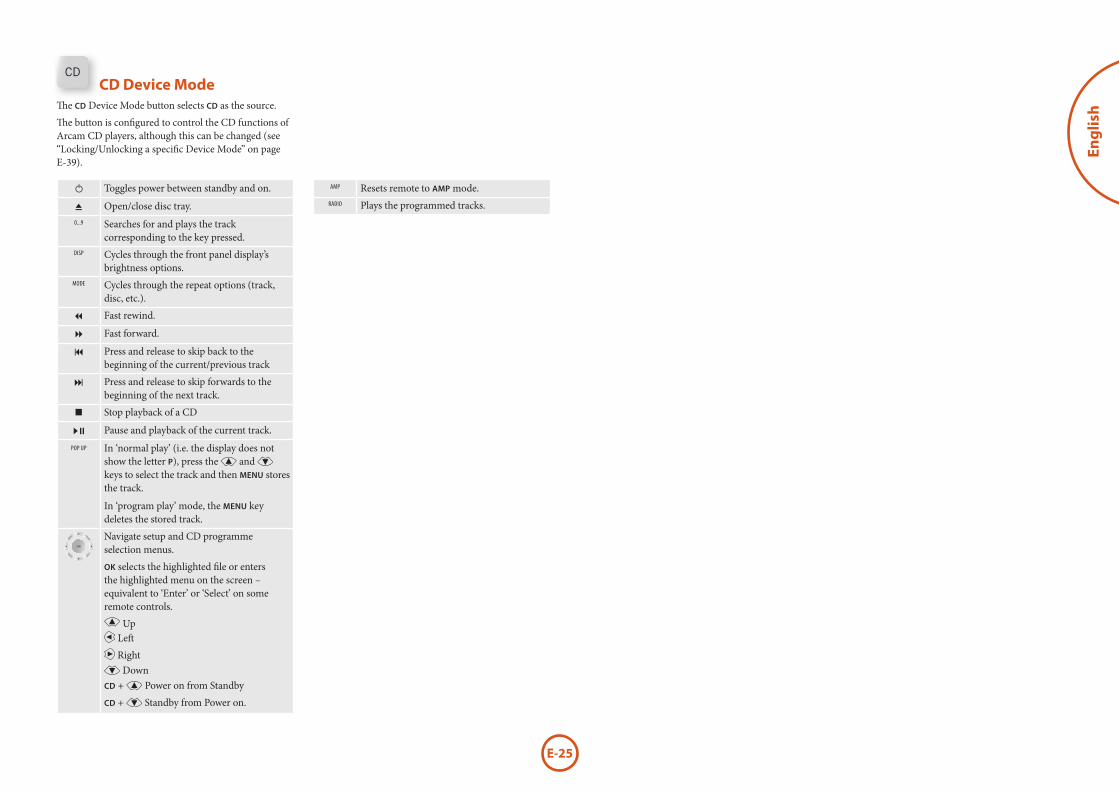
E-25
Eng
lish
2 Toggles power between standby and on.
1 Open/close disc tray.0...9 Searches for and plays the track
corresponding to the key pressed.DISP Cycles through the front panel display’s
brightness options.MODE Cycles through the repeat options (track,
disc, etc.).
7 Fast rewind.
8 Fast forward.
9 Press and release to skip back to the beginning of the current/previous track
: Press and release to skip forwards to the beginning of the next track.
Stop playback of a CD
4; Pause and playback of the current track.POP UP In ‘normal play’ (i.e. the display does not
show the letter P), press the ' and , keys to select the track and then MENU stores the track.
In ‘program play’ mode, the MENU key deletes the stored track.
Navigate setup and CD programme selection menus.
OK selects the highlighted file or enters the highlighted menu on the screen – equivalent to ‘Enter’ or ‘Select’ on some remote controls.
' Up< Left
> Right
, DownCD + ' Power on from Standby
CD + , Standby from Power on.
AMP Resets remote to AMP mode.RADIO Plays the programmed tracks.
CD Device ModeThe CD Device Mode button selects CD as the source.
The button is configured to control the CD functions of Arcam CD players, although this can be changed (see “Locking/Unlocking a specific Device Mode” on page E-39).
E-26
Before you use your Receiver it is essential that you enter some information into the Setup menus about your speaker configuration. This allows the Receiver to process any surround sound digital source to exactly match your system and give you the ultimate surround sound experience.
There are three pieces of vital information which are outlined in the sections: ‘Speaker Types’, ‘Speaker Distances’ and ‘Speaker Levels’.
The way you enter this information manually into the Receiver is given later in the ‘Setup Menus’ section on page E-28. The settings can also be established automatically using the Arcam Auto Speaker Setup function. However it is important to understand why these speaker settings must be entered, which is why this section is presented first.
Speaker typesYou need to set the type of speakers that you have connected to your Receiver:
Large capable of full frequency range reproductionSmall not capable of full frequency range
reproduction at the low frequency endNone speaker not present in your configuration
The terms ‘Large’ and ‘Small’ do not necessarily relate to the physical size of your speakers. As a rule of thumb, if a speaker cannot reproduce a flat frequency response down to about 40Hz (and very few can!) it is often better to consider them as ‘Small’ for setup purposes of home cinema.
When a speaker is set to ‘Small’, very low frequency sounds are redirected away from that speaker to a ‘Large’ speaker or a subwoofer, which are far better suited to reproducing these low frequency sounds.
Note that it is not possible to set all speakers to ‘Small’ unless there is a subwoofer in your speaker configuration. If you do not have a subwoofer, you will be forced to set your front speakers to ‘Large’.
(Advanced users may wish to automatically override the ‘Small’ speaker setting for purely stereo music listening when not watching movies. This can be achieved in the ‘Input Config.’ menu – see page E-29.
essential setup
Crossover frequency
If you have set any speakers as being Small, then you will be required to set a value for the crossover frequency. This is the frequency below which signals are filtered away from these Small speakers and redirected to Large speakers or the subwoofer (if present). A frequency of 80Hz is often a good starting point, however you will probably have to experiment with different values to find the best value for your system or consult your speaker handbook.
Use Channels 6+7 for
If not used in the main zone, it is possible to assign the Surround Back channels to Height 1, bi-amp the Front Left/Right channels or to provide an amplified output to Zone 2.
Speaker DistancesIt is essential for the distance from each speaker to the listening position to be accurately measured and entered into the ‘Setup’ menu. This ensures that the sounds from the various speakers arrive at the listening position at the correct time to recreate a realistic surround effect. The distance can be entered in centimetres or inches.
Speaker LevelsFinally the levels of all the speakers in the system need to be adjusted to match each other at the listening position, again to create a proper surround effect. To help with this the Receiver can generate a test noise for each speaker which should be measured with a sound pressure level (SPL) meter. The meter should be set to ‘C’ weighting and slow response. Several smartphone/tablet apps are available which can also perfom this function. The level of noise measured at the listening position from each speaker should be adjusted on the Speaker Trims page of the Setup menu so that the meter reads 75dB SPL. It does not matter what the system volume setting of the Receiver is before turning the test noise on as the volume setting is over-ridden for the duration of the speaker noise test.
There are several basic SPL meters on the market at reasonable prices aimed at home cinema enthusiasts. Check your local technology store, search online or ask your dealer.
If you do not have an SPL meter or suitable app, you can try to adjust the noise level of each speaker by ear. In this case it is not possible to adjust the speakers to the absolute 75dB SPL volume level, but you should aim for all speakers sounding equally loud. Setting speaker test noise levels by ear is not recommended as it is very difficult to do accurately, but is often better than doing nothing at all!

E-27
Eng
lishauto speaker
setupDirac Live for ArcamThere is a proprietary automatic loudspeaker setup function built into your Receiver from Dirac Reasearch. Using a PC/MAC based application, this attempts to set all the essential speaker settings for all the speakers in your system. It also calculates room equalisation (Room EQ) filter values to remove some of the worst effects of resonant frequencies in the listening room.
Your Receiver package is supplied with a calibration microphone, which should be inserted into the microphone input of the supplied USB sound card and then into a USB socket on a PC or MAC connected to the same network as the Receiver and positioned as directed by the Dirac Live for Arcam PC/MAC application. This microphone picks up the special calibration tones generated by the speakers when Dirac Live for Arcam application is run. The Receiver then analyses the signal and computes:
< speaker type, < speaker distance, < speaker level, < problem resonant frequencies in the room which need control by filtering.
To help the system be as accurate as possible when performing Dirac Live for Arcam setup, there are a few guidance rules that should be followed:
< Minimise any background sounds in the listening room and other nearby rooms. < Close all windows and doors in the listening room. < Turn off all fans including air-conditioning systems. < Mounting the microphone on a tripod or similar. < Position the set up microphone pointing upwards at roughly head height in the normal listening position. It is not necessary to point the microphone directly at the speaker generating the test tone. (It helps if you are able to position the microphone exactly where your head would normally be for listening, with the microphone in direct unobstructed view of all speakers.) < If your system includes an active subwoofer, start by setting its output level / gain control to a value roughly matching the front speakers.
When activated, a calibration tone is played through each channel of the Receiver in turn, including the subwoofer channel. The calibration tone cycles round each of the speakers multiple times as the different parameters are calculated. If you do not have a full 7.1 speaker (on the “floor”) configuration there will be periods of silence between some speaker channels. Follow the ‘progress’ information on your PC/MAC.
By default, Room EQ is not applied to any of the source inputs. You should enable Room EQ on inputs you think benefit from this feature, as required, by listening when playing typical source material through each input. After being calculated, this is enabled from within the Input Config menu.
While room equalisation can help to reduce problems with listening room acoustics, it is usually far better to try to solve these problems with the room directly. Proper loudspeaker positioning, acoustic wall treatments and moving the listening position away from walls should produce far better results overall. However it may be difficult to do this in a home environment, so Room EQ is your next best choice.
ProblemsWe advise you to look over the reported measurements on the screen following Auto Speaker Setup for any obviously incorrect results, in particular to ensure the reported speakers match your configuration and that the speaker distances to the listening position appear look roughly correct. If the results are not what you expected re-run Auto Speaker Setup.
The Auto Speaker Setup function is normally quite accurate but occasionally false results can be generated. Problems may be as a result of:
< external sounds or rumbling/handling noises picked up by the microphone < sound reflections off hard surfaces (e.g. windows or walls) close to the listening position, < very strong acoustic resonances within the room, < obstacles (such as a sofa) between speakers and the microphone.
If you are still experiencing difficulties or you wish to have the most accurate results for ultimate surround performance, we recommend using the manual method of establishing speaker distances and levels.
Using subwoofersIf your system includes one or two active subwoofers you may need to set the subwoofer output level/gain control set to a higher or lower value.
Please refer to the Dirac application and quick start guide for full details of how to use the system with your Receiver.
Downloading the Dirac Live for Arcam applcationTo download the Dirac Live for Arcam PC/MAC application and quick start guide, please visit:
www.arcam.co.uk
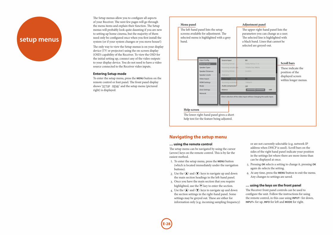
E-28
The left-hand panel lists the setup screens available for adjustment. The selected menu is highlighted with a grey band.setup menus
The Setup menus allow you to configure all aspects of your Receiver. The next few pages will go through the menu items and explain their function. The Setup menus will probably look quite daunting if you are new to setting up home cinema, but the majority of them need only be configured once when you first install the system (or if your system changes or you move house!)
The only way to view the Setup menus is on your display device (TV or projector) using the on-screen display (OSD) capability of the Receiver. To view the OSD for the initial setting up, connect any of the video outputs to your display device. You do not need to have a video source connected to the Receiver video inputs.
Entering Setup modeTo enter the setup menu, press the MENU button on the remote control or font panel. The front panel display shows ‘SETUP MENU’ and the setup menu (pictured right) is displayed.
Navigating the setup menu
… using the remote controlThe setup menu can be navigated by using the cursor (arrow) keys on the remote control. This is by far the easiest method.1. To enter the setup menu, press the MENU button
(which is located immediately under the navigation buttons).
2. Use the ' and , keys to navigate up and down the main section headings in the left-hand panel.
3. Once you have the main section that you require highlighted, use the > key to enter the section.
4. Use the ' and , keys to navigate up and down the section settings in the right-hand panel. Some settings may be greyed out. These are either for information only (e.g. incoming sampling frequency)
or are not currently selectable (e.g. network IP address when DHCP is used). Scroll bars on the sides of the right hand panel indicate your position in the settings list where there are more items than can be displayed at once.
5. Pressing OK selects a setting to change it, pressing OK again de-selects the setting.
6. At any time, press the MENU button to exit the menu. Any changes to settings are saved.
… using the keys on the front panelThe Receiver front panel controls can be used to configure the unit. Follow the instructions for using the remote control, in this case using INPUT– for down, INPUT+ for up, INFO for left and MODE for right.
The lower right-hand panel gives a short help text for the feature being adjusted.
These indicate the position of the displayed screen within longer menus.
Speaker Types
Input Config
General Setup
Speaker Distances
Speaker Levels
Video Inputs
HDMI Settings
Mode
Zone Settings
Network
Source Input BD
Incoming format Dolby Atmos 7.1.4
Incoming sample rate
Incoming bitrate
Dialnorm
Video Input
Incoming resolution
Audio compression
Balance
192kHz Out: 96kHz
Lossless
--
BD
1080p50
0dB
Direct selection of the video input without changing the audio input.
Off
Menu panel
The upper right-hand panel lists the parameters you can change as a user. The selected line is highlighted with a black band. Lines that cannot be selected are greyed-out.
Adjustment panel
Scroll bars
Help screen
E-29
Eng
lish
Input Config.The audio and video settings on this page of the Setup menu can be tailored specifically and independently to the currently selected input.
When a different input is selected on the Input line, all the input-specific settings for that input are displayed below it. These settings are applied to the named Input only and are stored in memory and recalled each time the unit is powered up and whenever that input is selected.
Input – The currently selected input connectors to which the settings below relate.
Name – The display name of the input. You can change the name of any input to more closely match your setup. For example, if you had two satellite receivers, you could connect the main receiver to the Sat audio and video input connectors and change the Name to ‘SAT 1’. You could then connect the second satellite receiver to the VCR audio and video input connectors, but change the VCR Name to ‘SAT 2’. It is then clearer to users of your Receiver which inputs they wish to select when scrolling though.
Lip Sync – Each input can have its own setting to add a time delay between the audio and video signals to compensate for the sound and picture not being synchronised. This is normally required when video processing is used in the system for scaling or de-interlacing video. The range of lip sync delay is 0 to 250 milliseconds.
The lip sync adjustment can only correct for delayed video. If the audio is late set lip sync to its minimum.
Mode – Sets the initial audio decode mode for stereo sources on this input.
< Last Mode recalls the last used setting for this input when a stereo source was applied. See section “Two-channel source modes” on page E-32 for more information.
Ext. Mode – Sets the initial audio decode mode for multi-channel digital sources on this input.
< Last Mode recalls the last used setting for this input when a stereo source was applied. See section “Multi-channel source modes” on page E-32 for more information.
Bass –
Treble –
These allow you to alter the bass and treble tone controls for all currently active speakers for each individual
input. For example, if your PVR source sounds a little bass light, you can always correct for this by selecting PVR on the Input line at the top of this menu and add 2 or 3dB to the Bass control. Then, whenever the PVR input is selected, the bass is automatically boosted for as long as that input is selected.
Room EQ – When the Auto Speaker Setup function is run it also calculates Room Equalisation coefficients to remove some of the worst effects of resonant frequencies of the room at the listening position. By default Room EQ is not applied to any of the source inputs, however you can enable them on a per-input basis as you wish.
< Not Calculated: (Information only) Auto Speaker Setup has not been run or has errors so cannot be selected. < Project Name: Dirac Live for Arcam Room EQ is applied to the current source and will display the name of the project from the Dirac Live application. < Off: Dirac Live for Arcam Room EQ is not applied to the current source.
Input Trim – Sets the maximum analogue input signal level (sensitivity) on this input before the ADC (Analogue-to-Digital converter) signal path clips. Options are 1, 2 and 4 volts RMS maximum input. The default is 2Vrms maximum.
For example, analogue sources with low output levels may benefit by choosing the 1V maximum setting. This helps maximise signal-to-noise performance of the Receiver and also helps keep the various analogue sources sounding about the same level for any given Receiver volume control setting.
Dolby Volume –Dolby Volume is an intelligent system that improves the perceived audio frequency response at lower listening levels and corrects for volume inconsistencies between sources (e.g. a rock radio station and a BD) and between programming (e.g. a TV show and advertisement breaks).
< On: Dolby Volume is applied to this input. < Off: (default) Dolby Volume is not applied to this input.
Dolby Leveller – This setting of Dolby Volume controls how closely quiet and loud sources and programme content are matched to each other, based on the ear’s perception of loudness. The range of values is 0 (minimal levelling) to 10 (maximum levelling). The default setting is 2, however we recommend experimenting with higher values if your source material is less closely matched in level. If the Volume Leveller function is set off, no level matching between sources
and programme material is performed. Note however that turning the Dolby Leveller setting of Dolby Volume to ‘Off ’ is not the same as turning the entire function of Dolby Volume to ‘Off ’, as volume related frequency response processing is still active. See “Dolby volume” on page E-34 for more information.
DV Calib. Offset – The Calibration Offset parameter of Dolby Volume allows you to compensate for speaker efficiencies and listening position. The default value is 0 and this should normally produce a good result when the Receiver speaker levels are set using a sound pressure level meter.
See “Dolby volume” on page E-34 for further information on Calibration Offset.Stereo Mode – If you have configured your system to have a subwoofer, then you have the flexibility to choose how bass information is distributed between the front left/right speakers and the subwoofer when listening to stereo (two channel only) analogue and digital sources. Choose the option which gives you the most solid, even sounding bass. If you are using a subwoofer for stereo, please also see Sub Stereo below to set the level of the subwoofer. For best results test with a setup disc or live programme material. This setting can be used to override your normal speaker settings in the Spkr Types menu whenever the Receiver plays stereo material. It is quite common to find that two channel stereo music listening is best done with a slightly different sub/speaker setting than for surround movies.
< As Spkr Types: When an analogue or digital stereo source is played, your normal speaker configuration (as in Spkr Types menu) is used to reproduce the signal. < Left/Right: Full frequency stereo information. All audio is sent to the front left and right speakers only without any bass redirection. You can use this setting if you consider your front left/right speakers to be able to handle the full frequency range of music. If you have set your front left/right speaker size as Small in the Spkr Types setup page, you may wish to use this option to override the setting to Large for stereo music listening, if you have full frequency range left/right speakers. It can often be beneficial to set full frequency range speakers to Small in the Spkr Types setup page for use with movies, if you have a subwoofer in your system. Doing so may deliver more impact on movie soundtracks as subwoofers are designed to handle reproduction of high bass content. However you may find that for stereo music a better overall
result is obtained by not using the subwoofer and effectively treating the front left/right speakers as Large. < Left/Right+Sub: Full frequency range stereo is fed to the front left and right speakers and extracted bass is sent to the subwoofer. In this case the low frequency information is effectively duplicated. < Sat+Sub: Use this setting if you really do have Small satellite front left and right speakers, or if you prefer the overall sound of bass being handled by the subwoofer. Full bass management is used so that analogue and digital stereo sources are fed to the DSP where the bass is filtered off front left and right and redirected to the subwoofer.
NOTE
The Stereo Mode function is not available when using an analogue source in Stereo Direct mode.
Sub Stereo – If Left/Right+Sub or Sat+Sub is selected in Stereo Mode above, this setting adjusts the level of the subwoofer when the source is two channel stereo.
Audio Source – Selects the particular connection type for each input. The default is HDMI; this setting must be changed if another connection is used.
Select from the list the audio type you are using on this source.
< HDMI: the unit is forced to use the HDMI audio input for this source. < Digital: the unit is forced to use the optical (TOSLINK) or coaxial (S/PDIF) digital audio input for this source < Analogue: the unit is forced to use the analogue audio input for this source.
CD Direct – Turns off the compressed audio detection mute delay and should only be used for sources that will only transmit PCM audio (e.g. a CD player).
General SetupGeneral information and system controls.
Source Input – (Information only) The currently selected input to which the settings below relate.
Incoming Format – (Information only) The format of the digital audio stream connected to this input, if present.
E-30
Incoming Sample Rate – (Information only) The sample rate of the digital audio stream connected to this input, if present.
Incoming Bit Rate – (Information only) The bit rate of the digital audio stream connected to this input, if present.
Dialnorm – (Information only) If a Dolby Digital audio stream is connected to this input, this is the Dialogue Normalisation setting requested by the stream.
Video Input – The currently selected video input. For inputs that have video connections (e.g. SAT, PVR etc), audio and video inputs normally switch over together. However, here you can temporarily select a different video source for the current audio source. This feature may be useful, for example, if you are watching a sports game on satellite but on this occasion wish to listen to the commentary on the radio instead. This temporary override is reset when the input source is changed so that the Video Input follows the Audio Input setting (or the setting in the Video Inputs menu, if applicable).
Incoming Resolution – (Information only) Shows the incoming video resolution.
Audio Compression – Allows selection of compression which is ideal for late night listening. The compression effect increases the volume of the quiet passages and decreases the volume of the louder passages. Compression only applies to Dolby soundtrack formats that support this function (DTS is not supported).
< Off: (default) no audio compression is applied. < Medium: compression is applied so that loud portions of a soundtrack are reduced in level. Dolby True HD stream is compressed automatically as set by the incoming stream. < High: the maximum amount of dynamic range compression is applied, so that the difference between loud and quiet portions of a soundtrack is minimised.
This setting applies to all inputs when a relevant digital audio stream is detected. It is stored in memory and recalled each time the unit is powered up.
Balance – To alter the sound balance temporarily between front left and right speakers. You can alter the sound stage to either the left or the right by up to 6dB. Note that it is not possible to shift the audio signal completely over to one channel. This function resets to equal left/right balance when the input is changed.
Dolby Centre Spread – Allows adjustment of the sound field for Dolby Surround mode decoding of two-channel sources.
< Dolby Centre Spread: Controls the centre image width.With Dolby Surround decoding, dominant centre signals come only from the centre speaker. If no centre speaker is present, the decoder splits the centre signal equally to the left and right speakers to create a ‘phantom’ centre image. The Centre Spread control allows variable adjustment of the centre image so it may be heard only from the centre speaker; only from the left/right speakers as a phantom image; or from all three front speakers to varying degrees.
Digital Output Freq. – Sets the sampling frequency of the audio Analogue-to-Digital converter. This setting applies to all inputs when analogue audio is being processed (i.e. not Stereo Direct mode). It is stored in memory and recalled each time the unit is powered up.
Maximum Volume – Limits the maximum volume setting the system can be turned up to in the main zone. This is a useful feature to prevent accidental overdriving of low power-handling speakers (for example). It is stored in memory and recalled each time the unit is powered up.
Max On Volume – Limits the maximum volume the system operates in the main zone when it is switched on or comes out of Standby. The system comes on at this stored volume setting if the last used (possibly very loud) volume exceeds this value. It is stored in memory and recalled each time the unit is powered up.
Display on time – Sets the time that the front panel display remains illuminated after receiving a command. The default is always on.
CEC Control (Ouput 1 only) – Enables or disables HDMI CEC control, a system that allows devices connected with HDMI to control other compatible connected devices.
< Off: disables CEC Control < Output 1
ARC Control (Output 1 only) – Enables or disables the HDMI Audio Return Channel. This allows for television sound to be sent back to the Receiver, via the ‘Display’ input. ARC Control depends on CEC control being set.
HDMI Audio To TV – Enables or disables the transmission of HDMI audio from the HDMI output connector. Enable this setting if you wish to be able to listen using your TV speakers.
Control – Enables or disables RS232 or IP (NET) control, a system that allows control from various third-party home automation systems. Note, only RS232 or IP control can be used, not both.Power on – Determines how the unit powers on.
< Stby: in Standby mode < On: On < Last state: Last state (default).
Standby Mode – Determines what functionality is retained while in standby.
< Low Power: Lowest power setting < IP & HDMI ON: Allows for IP control & HDMI bypass while in standby, but consumes more power.
Language – Select the language for the OSD menu - English, French, German, Spanish, Dutch, Russian, Chinese.
Speaker TypesSettings for the types of loudspeaker you have connected in your configuration. These settings are applied to all audio inputs and are stored in memory and recalled each time the unit is powered up.Front Left/Right – Centre – Surr. Left/Right – Surr. Back L/R –Height 1 –Height 2 –Subwoofer –
Here you set the type of speakers that you have connected to your Receiver:
< Large: capable of full frequency range reproduction < Small: not capable of full frequency range reproduction at the low frequency end < None: speaker not present in your configuration < Height 1, 2: configures the type of height speakers - height/Dobly enabled. < Subwoofer: Sets whether you have none, 1 or 2 subwoofer(s) present.
NOTE
It is not possible to set all speakers to Small unless there is a subwoofer in your speaker configuration. If you do not have a subwoofer, you will be forced to set your front speakers to Large.
Crossover Freq – This is the frequency at which loudspeakers set as Small start to redirect bass signals to the Subwoofer or Large speakers in your system. Small speakers redirect bass to the subwoofer, if present. The exception is the Centre speaker which, if Small, redirects its bass to front left/right provided that they themselves are Large. This is done to help keep Centre bass directly in front of the listening position.Dolby Speaker Crossover– This is the frequency at which height speakers set to small redicrect bass information.
Use Channels 6+7 for – If your main zone speaker set up does not include Surround Back Left and Right speakers, you can choose to use the Surround Back amplifier channels as the Height 1 amplifiers, to Bi-Amp the Front Left and Right pair, or as a stereo power amplifier for Zone 2.
Speaker DistancesCalibration settings for the distances between the loudspeakers and the listening position.
NOTE
Speakers that are not present in your configuration will be greyed out.
If Dirac Live for Arcam is used, these settings will also be greyed out as they are autoset by Dirac
These settings are applied to all audio inputs and are stored in memory and recalled each time the unit is powered up.
Units – Select whether you wish to measure distances in imperial or metric units.Front Left – Centre – Front Right – Surr. Right – Surr. Back Right – Surr. Back Left – Surr. Left – Left Top Front/Middle/Back –Right Top Front/Middle/Back –Subwoofer –
As described in “essential setup” on page E-26, measure the distance from each loudspeaker in your system to your ear in the main listening position and enter the

E-31
Eng
lish
values. This allows the Receiver to calculate the correct relative delay for each loudspeaker.
Speaker LevelsCalibration settings for the test noise signal level through the loudspeakers and measured at the listening position.
NOTE
Speakers that are not present in your configuration will be greyed out.
If Dirac Live for Arcam is used, these settings will also be greyed out as they are autoset by Dirac
These settings are applied to all audio inputs and are stored in memory and recalled each time the unit is powered up.Use the ' and , navigation buttons on the remote control to select the relevant speaker. Press O to enable/disable the calibration noise and the < and > navigation buttons to adjust the noise level from each speaker.
Front Left – Centre – Front Right –Surr. Right – Surr. Back Right – Surr. Back Left – Surr. Left – Left Top Front/Middle/Back –Right Top Front/Middle/Back –Subwoofer –
As described in “essential setup” on page E-26, adjust the level of the test noise from each speaker so that an SPL meter at the listening position measures 75dB SPL.
Video InputsSettings to optionally assign a video source to each of the normally audio-only inputs. These settings are stored in memory and recalled each time the unit is powered up.Video Input CD – Video Input Aux – Video Input FM – Video Input USB – Video Input Net –
Video Input DAB –
The default for each of the audio inputs is ‘None’. You could, however, associate ‘Sat’ video with FM or Digital Radio audio to receive radio commentary of a sports game with pictures from satellite coverage, for example.
HDMI SettingsThe settings in this menu control the output resolution from the video processor in the Receiver. These settings are applied to all video inputs and are stored in memory and recalled each time the unit is powered up.
HDMI1 OSD – Selects whether the main zone pop-up OSD messages are On or Off. It is stored in memory and recalled each time the unit is powered up.
< When On, all user adjustments that are made during the general use of the Receiver are displayed on screen as well as the front panel display. This includes the adjustment of volume, subwoofer level, lip sync, tone controls, etc. It is stored in memory and recalled each time the unit is powered up. < When Off, the above user adjustments will not appear on screen, only on the front panel display. This leaves the picture on your display device clear of pop-up text. However, regardless of this setting the Setup menus are always displayed on screen.
HDMI Output 1080p – This setting controls the output resolution of the HDMI output when receiving 1080p input - bypass or upscale to 4k2k.
Lipsync – (Information only) Displays how much lip sync is automatically applied to the HDMI output to compensate for video processing delays in the attached display device. Not all display devices support this function.
ModeLists the decode and downmix options you wish to include when cycling through the options on the MODE button. Settings are Yes or No. The list is divided into two sections depending on the source audio type. See section “decoding modes” on page E-32 for more information on each processing and decoding mode.
These settings are applied to all audio inputs and are stored in memory and recalled each time the unit is powered up.
For Stereo sources:Dolby Surround – DTS Neural:X -5/7 Ch Stereo -
The first section, ‘Stereo sources’ is the list of processing modes you wish to make available for stereo signals (analogue stereo, digital PCM stereo, Dolby 2.0, DTS 2.0, etc). When a stereo signal is applied, each press of the MODE button cycles through the processing modes you have enabled in the ‘Stereo sources’ section. The unprocessed Stereo option is always available for stereo signals therefore it is not shown in the list.
For Multi-channel sources:Stereo Downmix –
Dolby Surround –
DTS Neural:X -
The second section, ‘Multi-channel sources’ is the list of processing modes you wish to make available for multi-channel digital signals (any Dolby or DTS digital stream that has more channels than stereo 2.0). When a multi-channel digital signal is applied, each press of the MODE button cycles through the processing modes you have enabled in the ‘Multi-channel sources’ section.
Zone Settings Lists the volume and control settings for Zone 2. These settings are applied to all audio inputs and are stored in memory and recalled each time the unit is powered up.
Z2 Input – Selects the analogue audio and composite video source to be routed to Zone 2. The default is ‘Follow Z1’, i.e. the same source as currently selected in Zone 1.Zone 2 Status – Selects if Zone 2 is in Standby or On.Zone 2 Volume – The current volume in Zone 2.Zone 2 Max. Vol – Limits the maximum volume setting the system can be turned up to in the Zone 2. This is a useful feature to prevent accidental overdriving of low power-handling speakers, for example.Zone 2 Fixed Vol – The Zone 2 volume control can be locked at the current value for use with an external amplifier with its own volume control in Zone 2.
Zone 2 Max On Vol – Limits the maximum volume the system operates in the Zone 2 when it is switched on or comes out of Standby. The system comes on at this volume if the last used (possibly very loud) volume exceeds this value.
NetworkThe Receiver is fitted with an network audio client which is capable of playing internet radio stations as well as stored music on a network storage device such as a PC, or on a USB flash drive.
Use DHCP – Select if your network uses DHCP < No: To assign a fixed IP address manually. < Yes: To use network parameters given by the DHCP server.
IP Address – If not using DHCP, enter the IP address you have assigned to the Receiver for your network.
Subnet Mask – If not using DHCP, enter the subnet mask for the Receiver on your network.
Gateway – If not using DHCP, enter the IP address of the router the Receiver is connected to.
Primary DNS – If not using DHCP, enter the Primary DNS IP address of your internet service provider.
Alternate DNS – If not using DHCP, enter the Secondary DNS IP address of your internet service provider.
MAC address – (Information only) The unique address of the network card in your Receiver.
Friendly name – Allows you to rename the network “friendly name” of your Receiver.
E-32
IntroductionYour Receiver receiver provides all the key decoding and processing modes for analogue and digital signals, including the latest high definition audio formats over HDMI.
Modes for digital sourcesDigital recordings are usually encoded to include information about their format type. The Receiver detects automatically the relevant format in a digital signal – such as Dolby Atmos, TrueHD, Dolby Digital Plus, DTS:X, DTS-HD Master Audio, Dolby Digital, or DTS – and switches in the appropriate decoding.
Modes for analogue sourcesAnalogue recordings do not contain information about their encoding formats, so the desired mode – such as Dolby Surround – needs to be selected manually.
Mode memoryDolby Digital or DTS audio (including the high definition formats) can be output in two mix modes, selected using the MODE button:
< Surround (e.g., five main channels plus a subwoofer for a 5.1 source) < Stereo downmix.
Two-channel audio, regardless of whether it is analogue or digital can also be output in two mix modes, selected using the mode button:
< Surround (e.g., Dolby Surround, DTS Neural:X, etc.) < Stereo.
The Receiver stores the settings for each source. Thus the decoding mode for the following groups of source material can be stored independently:
< Dolby Digital (multi-channel) and DTS source material < Two channel Dolby, PCM or Analogue source material
Two-channel source modesThe following decoding and surround modes are for creating multi-channel stereo modes from 2-channel sources. They are available on the AV860/AVR850/AVR550/AVR390 for standard and high definition Dolby Digital 2.0, DTS 2.0, PCM or analogue sources:Stereo –5/7 Channel Stereo –Dolby Surround –DTS Neural:X-
StereoIn this mode the AV860/AVR850/AVR550/AVR390 works as a conventional high quality audio amplifier. Note that if the subwoofer is enabled in stereo mode, then some processing of the signal is carried out.
< Stereo Direct: this achieves the best sound quality if an analogue connection is present. < 5/7 Channel Stereo: this produces an output from all speakers by copying the left output to all left speakers and the right output to all right speakers. The centre speaker outputs a mix of left and right.
Dolby SurroundDolby Surround allows the AV860/AVR850/AVR550/AVR390 to derive up to 7.1.4 outputs from a two or multi-channel source to take better advantage of all amplifiers and speakers in your setup.
DTS Neural:XDTS Neural:X provides up to 12 channels of decoding from stereo material. The AV860/AVR850/AVR550/AVR390 will derive separate channels corresponding to the standard home theatre layout.
Multi-channel source modesDigital multi-channel source material is normally provided as ‘5.1 audio’. The ‘5.1 channels’ comprise of: left, centre and right front speakers, two surround speakers and a low frequency effects (LFE) channel. Since the LFE channel is not a full range channel, it is referred to as ‘.1’.
Surround systems decode and reproduce the 5.1 channels directly. The DTS-ES matrix enhanced decoding system creates one extra rear channel from information buried in the two surround signals of the 5.1 source. The ES enhanced system is sometimes referred to as a ‘6.1’ system. This extra surround back
decoding modes
channel is normally reproduced through two separate loudspeakers, creating a ‘7.1’ system.
DTS-ES discrete is a true ‘6.1’ source, with six discretely encoded channels, plus the ‘.1’ LFE channel.
Dolby Digital Plus, Dolby TrueHD, Dolby Atmos, DTS:X and DTS-HD are high-resolution surround formats found on Blu-Ray discs
Decoding modesThe modes given in the following table are available for multi-channel digital sources.
Special modes such as DTS-ES 6.1 discrete, Dolby Digital Plus, Dolby TrueHD, Dolby Atmos, DTS:X and DTS-HD are only available from the correct source material.
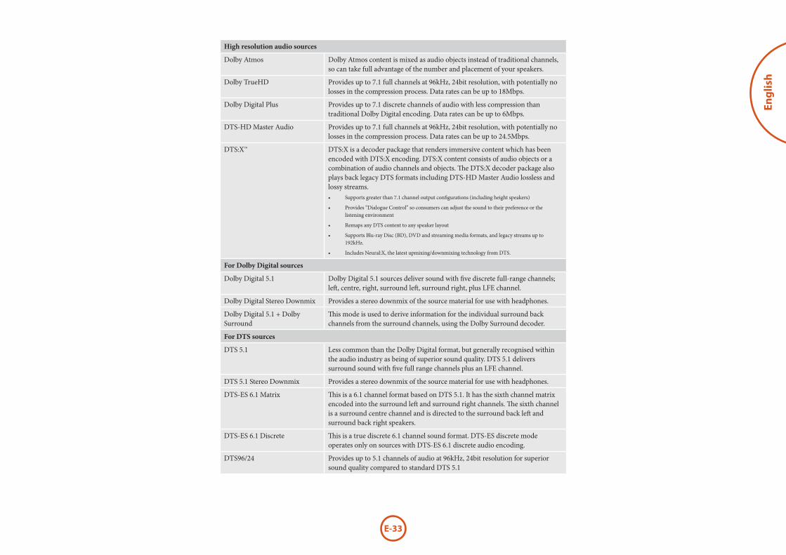
E-33
Eng
lish
High resolution audio sources
Dolby Atmos Dolby Atmos content is mixed as audio objects instead of traditional channels, so can take full advantage of the number and placement of your speakers.
Dolby TrueHD Provides up to 7.1 full channels at 96kHz, 24bit resolution, with potentially no losses in the compression process. Data rates can be up to 18Mbps.
Dolby Digital Plus Provides up to 7.1 discrete channels of audio with less compression than traditional Dolby Digital encoding. Data rates can be up to 6Mbps.
DTS-HD Master Audio Provides up to 7.1 full channels at 96kHz, 24bit resolution, with potentially no losses in the compression process. Data rates can be up to 24.5Mbps.
DTS:X™ DTS:X is a decoder package that renders immersive content which has been encoded with DTS:X encoding. DTS:X content consists of audio objects or a combination of audio channels and objects. The DTS:X decoder package also plays back legacy DTS formats including DTS-HD Master Audio lossless and lossy streams.• Supports greater than 7.1 channel output configurations (including height speakers)
• Provides “Dialogue Control” so consumers can adjust the sound to their preference or the listening environment
• Remaps any DTS content to any speaker layout
• Supports Blu-ray Disc (BD), DVD and streaming media formats, and legacy streams up to 192kHz.
• Includes Neural:X, the latest upmixing/downmixing technology from DTS.
For Dolby Digital sources
Dolby Digital 5.1 Dolby Digital 5.1 sources deliver sound with five discrete full-range channels; left, centre, right, surround left, surround right, plus LFE channel.
Dolby Digital Stereo Downmix Provides a stereo downmix of the source material for use with headphones.
Dolby Digital 5.1 + Dolby Surround
This mode is used to derive information for the individual surround back channels from the surround channels, using the Dolby Surround decoder.
For DTS sources
DTS 5.1 Less common than the Dolby Digital format, but generally recognised within the audio industry as being of superior sound quality. DTS 5.1 delivers surround sound with five full range channels plus an LFE channel.
DTS 5.1 Stereo Downmix Provides a stereo downmix of the source material for use with headphones.
DTS-ES 6.1 Matrix This is a 6.1 channel format based on DTS 5.1. It has the sixth channel matrix encoded into the surround left and surround right channels. The sixth channel is a surround centre channel and is directed to the surround back left and surround back right speakers.
DTS-ES 6.1 Discrete This is a true discrete 6.1 channel sound format. DTS-ES discrete mode operates only on sources with DTS-ES 6.1 discrete audio encoding.
DTS96/24 Provides up to 5.1 channels of audio at 96kHz, 24bit resolution for superior sound quality compared to standard DTS 5.1
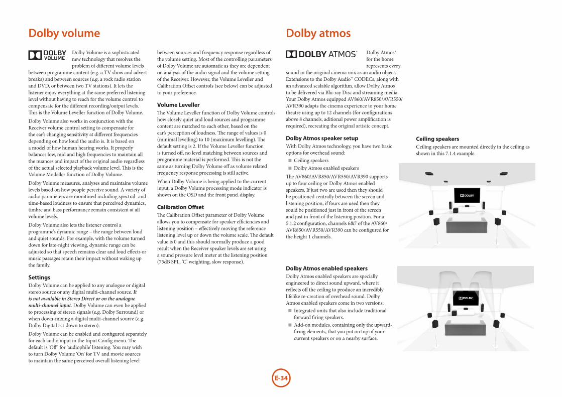
E-34
Dolby volumeDolby Volume is a sophisticated new technology that resolves the problem of different volume levels
between programme content (e.g. a TV show and advert breaks) and between sources (e.g. a rock radio station and DVD, or between two TV stations). It lets the listener enjoy everything at the same preferred listening level without having to reach for the volume control to compensate for the different recording/output levels. This is the Volume Leveller function of Dolby Volume.
Dolby Volume also works in conjunction with the Receiver volume control setting to compensate for the ear’s changing sensitivity at different frequencies depending on how loud the audio is. It is based on a model of how human hearing works. It properly balances low, mid and high frequencies to maintain all the nuances and impact of the original audio regardless of the actual selected playback volume level. This is the Volume Modeller function of Dolby Volume.
Dolby Volume measures, analyses and maintains volume levels based on how people perceive sound. A variety of audio parameters are monitored including spectral- and time-based loudness to ensure that perceived dynamics, timbre and bass performance remain consistent at all volume levels.
Dolby Volume also lets the listener control a programme’s dynamic range – the range between loud and quiet sounds. For example, with the volume turned down for late-night viewing, dynamic range can be adjusted so that speech remains clear and loud effects or music passages retain their impact without waking up the family.
SettingsDolby Volume can be applied to any analogue or digital stereo source or any digital multi-channel source. It is not available in Stereo Direct or on the analogue multi-channel input. Dolby Volume can even be applied to processing of stereo signals (e.g. Dolby Surround) or when down-mixing a digital multi-channel source (e.g. Dolby Digital 5.1 down to stereo).
Dolby Volume can be enabled and configured separately for each audio input in the Input Config menu. The default is ‘Off ’ for ‘audiophile’ listening. You may wish to turn Dolby Volume ‘On’ for TV and movie sources to maintain the same perceived overall listening level
between sources and frequency response regardless of the volume setting. Most of the controlling parameters of Dolby Volume are automatic as they are dependent on analysis of the audio signal and the volume setting of the Receiver. However, the Volume Leveller and Calibration Offset controls (see below) can be adjusted to your preference.
Volume LevellerThe Volume Leveller function of Dolby Volume controls how closely quiet and loud sources and programme content are matched to each other, based on the ear’s perception of loudness. The range of values is 0 (minimal levelling) to 10 (maximum levelling). The default setting is 2. If the Volume Leveller function is turned off, no level matching between sources and programme material is performed. This is not the same as turning Dolby Volume off as volume related frequency response processing is still active.
When Dolby Volume is being applied to the current input, a Dolby Volume processing mode indicator is shown on the OSD and the front panel display.
Calibration OffsetThe Calibration Offset parameter of Dolby Volume allows you to compensate for speaker efficiencies and listening position – effectively moving the reference listening level up or down the volume scale. The default value is 0 and this should normally produce a good result when the Receiver speaker levels are set using a sound pressure level meter at the listening position (75dB SPL, ‘C’ weighting, slow response).
Dolby atmosDolby Atmos® for the home represents every
sound in the original cinema mix as an audio object. Extensions to the Dolby Audio™ CODECs, along with an advanced scalable algorithm, allow Dolby Atmos to be delivered via Blu-ray Disc and streaming media. Your Dolby Atmos equipped AV860/AVR850/AVR550/AVR390 adapts the cinema experience to your home theatre using up to 12 channels (for configurations above 8 channels, aditional power amplification is required), recreating the original artisitc concept.
Dolby Atmos speaker setupWith Dolby Atmos technology, you have two basic options for overhead sound:
< Ceiling speakers < Dolby Atmos enabled speakers
The AV860/AVR850/AVR550/AVR390 supports up to four ceiling or Dolby Atmos enabled speakers. If just two are used then they should be positioned centrally between the screen and listening position, if fours are used then they sould be positioned just in front of the screen and just in front of the listening position. For a 5.1.2 configuration, channels 6&7 of the AV860/AVR850/AVR550/AVR390 can be configured for the height 1 channels.
Ceiling speakersCeiling speakers are mounted directly in the ceiling as shown in this 7.1.4 example.
Dolby Atmos enabled speakersDolby Atmos enabled speakers are specially engineered to direct sound upward, where it reflects off the ceiling to produce an incredibly lifelike re-creation of overhead sound. Dolby Atmos enabled speakers come in two versions:
< Integrated units that also include traditional forward firing speakers. < Add-on modules, containing only the upward-firing elements, that you put on top of your current speakers or on a nearby surface.

E-35
Eng
lishtuner
operation
The Receiver is fitted with a FM & DAB (digital radio) tuners. DAB broadcasts are not available in all locations.
This section deals with tuner operation, for information on setting up the tuner and installing aerials, see page E-13.
When a tuner input is selected, the OSD shows a list of radio presets plus an information panel giving all available information about the current frequency (for FM) or station (for DAB).
The front panel will also give the same information, pressing the INFO key will cycle through the various items of information:
FM
• Processing mode (default)• Radiotext (if available)• Programme type (if available)• Signal strength
DAB
• Processing mode (default)• Radiotext (if available)• Programme type• Signal quality• Bit-rate of transmission
Tuning/Channel SelectionWhen switching to the internal TUNER source, the Receiver enters the last used tuner band, be it FM or DAB. Repeatedly pressing RADIO cycles through the available tuner bands on your Receiver.
FM analogue radioFrequency tuning on FM radio is done using the < and > buttons on the remote control in TUN device mode. Individual presses move the frequency down and up one step. If you press and hold either of the tuning buttons for two seconds, the tuner scans to the next strong signal. You can stop a scan at any time by pressing one of the tuning buttons again.
In Europe, the internal FM radio is capable of receiving RDS (Radio Data System) radiotext signals that are transmitted on some stations. The RDS information typically includes the radio station name, the music or speech genre as well as additional information related to the current programme. On music stations this is often information on the currently playing track.
DAB digital radioDigital Audio Broadcasting (DAB) radio is becoming more widely available. See www.worlddab.org/country_information for information on DAB availability.
You will need to scan for available stations before being able to listen to them.To scan for DAB stations, first select the DAB tuner then press and hold O until the display indicates scanning has started. The Receiver will then scan all the DAB radio frequencies and compile a list of the stations that are available.When the scan is complete, you can scroll through the station list using the < and > buttons on the remote control. To listen to the currently displayed station press the O. If you do not press O within two seconds, the display will revert to displaying the currently playing station.
Internet radioPlease see the Network/USB Operation section on page E-36 for details of internet radio operation.
Saving and selecting PresetsPreset selection uses the ' and , keys on the remote to browse and O to select the preset when the remote is in TUN device mode.Up to 50 presets can be stored and these can be from any band, for example Preset 1 could be an FM station, preset two a DAB station, etc. Pressing the OK key causes the next available preset number to be displayed, then pressing the OK key again stores the current frequency/channel in that preset. If a different preset number is required, press the ' and , keys until the desired number is displayed before pressing the OK key for a second time.
Deleting PresetsWhen in tuner browse mode (using ' and , to scroll through the presets), the yellow button on the remote is used to delete the currently highlighted (but not playing) station or frequency.
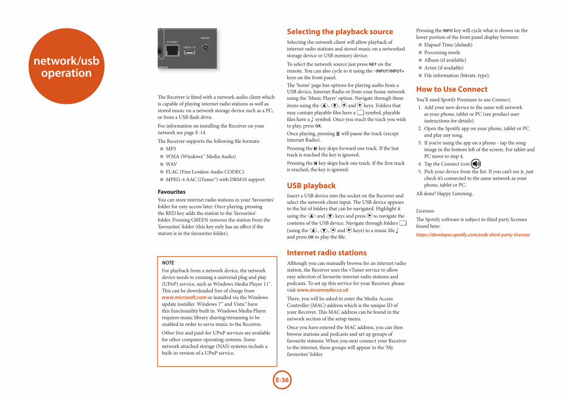
E-36
network/usb operation
The Receiver is fitted with a network audio client which is capable of playing internet radio stations as well as stored music on a network storage device such as a PC, or from a USB flash drive.
For information on installing the Receiver on your network see page E-14.
The Receiver supports the following file formats: < MP3 < WMA (Windows™ Media Audio) < WAV < FLAC (Free Lossless Audio CODEC) < MPEG-4 AAC (iTunes™) with DRM10 support
FavouritesYou can store internet radio stations in your ‘favourites’ folder for easy access later. Once playing, pressing the RED key adds the station to the ‘favourites’ folder. Pressing GREEN removes the station from the ‘favourites’ folder (this key only has an effect if the station is in the favourites folder).
Selecting the playback sourceSelecting the network client will allow playback of internet radio stations and stored music on a networked storage device or USB memory device.
To select the network source just press NET on the remote. You can also cycle to it using the –INPUT/INPUT+ keys on the front panel.The ‘home’ page has options for playing audio from a USB device, Internet Radio or from your home network using the ‘Music Player’ option. Navigate through these items using the ', ,, < and > keys. Folders that may contain playable files have a symbol, playable files have a symbol. Once you reach the track you wish to play, press OK.Once playing, pressing ; will pause the track (except Internet Radio).Pressing the / key skips forward one track. If the last track is reached the key is ignored.Pressing the 0 key skips back one track. If the first track is reached, the key is ignored.
USB playbackInsert a USB device into the socket on the Receiver and select the network client input. The USB device appears in the list of folders that can be navigated. Highlight it using the ' and , keys and press > to navigate the contents of the USB device. Navigate through folders (using the ', ,, < and > keys) to a music file and press OK to play the file.
Internet radio stationsAlthough you can manually browse for an internet radio station, the Receiver uses the vTuner service to allow easy selection of favourite internet radio stations and podcasts. To set up this service for your Receiver, please visit www.arcamradio.co.uk
There, you will be asked to enter the Media Access Controller (MAC) address which is the unique ID of your Receiver. This MAC address can be found in the network section of the setup menu.
Once you have entered the MAC address, you can then browse stations and podcasts and set up groups of favourite stations. When you next connect your Receiver to the internet, these groups will appear in the ‘My favourites’ folder.
Pressing the INFO key will cycle what is shown on the lower portion of the front panel display between:
< Elapsed Time (default) < Processing mode < Album (if available) < Artist (if available) < File information (bitrate, type).
How to Use ConnectYou’ll need Spotify Premium to use Connect.1. Add your new device to the same wifi network
as your phone, tablet or PC (see product user instructions for details).
2. Open the Spotify app on your phone, tablet or PC and play any song.
3. If you’re using the app on a phone - tap the song image in the bottom left of the screen. For tablet and PC move to step 4.
4. Tap the Connect icon 5. Pick your device from the list. If you can’t see it, just
check it’s connected to the same network as your phone, tablet or PC.
All done! Happy Listening.
Licenses
The Spotify software is subject to third party licenses found here:
https://developer.spotify.com/esdk-third-party-licenses
NOTE
For playback from a network device, the network device needs to running a universal plug and play (UPnP) service, such as Windows Media Player 11™. This can be downloaded free of charge from www.microsoft.com or installed via the Windows update installer. Windows 7™ and Vista™ have this functionality built in. Windows Media Player requires music library sharing/streaming to be enabled in order to serve music to the Receiver.
Other free and paid-for UPnP services are available for other computer operating systems. Some network attached storage (NAS) systems include a built-in version of a UPnP service.
OUTPUT1ARC
SUB 2
R
L
HEIGHT 1 HEIGHT 2
PREAMP OUT
~ 50 – 60 Hz 1.5KW MAX
1.2A MAX TRIG Z2 Z2 IR
TRIG Z1
RS232DC6V
Z1 IR
ZONE2OUT
OUTPUT2AV
AV
ETHERNET
USB 5V / 1A
115 230
FM/DAB
PVR
PVR
VCRBDSAT
SBR SR FR C FL SL SBL
SBRSUBSRFR
CFL SL SBL
SBRHEIGHT 1 RZONE 2 R
HEIGHT1 LZONE 2 L
SR FR C FL SL SBL
STBZ2 OUT
ZONE 2 RHEIGHT 1 R
CLA
SS 2
WIR
ING
ZONE 2 LHEIGHT 1 L
8Ω LOAD IMPEDANCE RECOMMENDED
PVRSATBDAV
BD
CD
CD
GAME
STB/MHL
STB
GAME
SPEAKER OUTPUTS
OPTICALCOAXIAL
DIGITAL AUDIO
ANALOGUE AUDIO
HDMI
PREAMP OUT
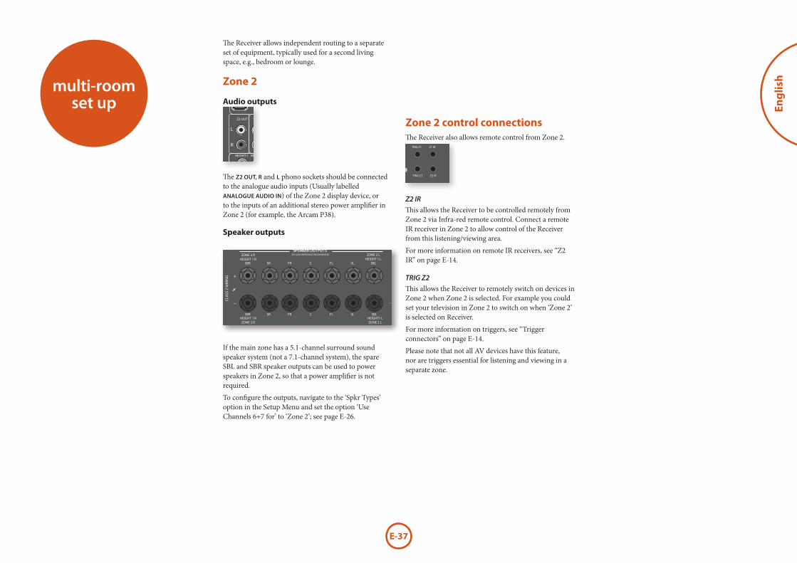
E-37
Eng
lish
Zone 2 control connectionsThe Receiver also allows remote control from Zone 2.
OUTPUT1ARC
SUB 2
R
L
HEIGHT 1 HEIGHT 2
PREAMP OUT
~ 50 – 60 Hz 1.5KW MAX
1.2A MAX TRIG Z2 Z2 IR
TRIG Z1
RS232DC6V
Z1 IR
ZONE2OUT
OUTPUT2AV
AV
ETHERNET
USB 5V / 1A
115 230
FM/DAB
PVR
PVR
VCRBDSAT
SBR SR FR C FL SL SBL
SBRSUBSRFR
CFL SL SBL
SBRHEIGHT 1 RZONE 2 R
HEIGHT1 LZONE 2 L
SR FR C FL SL SBL
STBZ2 OUT
ZONE 2 RHEIGHT 1 R
CLA
SS 2
WIR
ING
ZONE 2 LHEIGHT 1 L
8Ω LOAD IMPEDANCE RECOMMENDED
PVRSATBDAV
BD
CD
CD
GAME
STB/MHL
STB
GAME
SPEAKER OUTPUTS
OPTICALCOAXIAL
DIGITAL AUDIO
ANALOGUE AUDIO
HDMI
PREAMP OUT
Z2 IR
This allows the Receiver to be controlled remotely from Zone 2 via Infra-red remote control. Connect a remote IR receiver in Zone 2 to allow control of the Receiver from this listening/viewing area.
For more information on remote IR receivers, see “Z2 IR” on page E-14.
TRIG Z2
This allows the Receiver to remotely switch on devices in Zone 2 when Zone 2 is selected. For example you could set your television in Zone 2 to switch on when ‘Zone 2’ is selected on Receiver.
For more information on triggers, see “Trigger connectors” on page E-14.
Please note that not all AV devices have this feature, nor are triggers essential for listening and viewing in a separate zone.
multi-room set up
The Receiver allows independent routing to a separate set of equipment, typically used for a second living space, e.g., bedroom or lounge.
Zone 2
Audio outputsOUTPUT1
ARC
SUB 2
R
L
HEIGHT 1 HEIGHT 2
PREAMP OUT
~ 50 – 60 Hz 1.5KW MAX
1.2A MAX TRIG Z2 Z2 IR
TRIG Z1
RS232DC6V
Z1 IR
ZONE2OUT
OUTPUT2AV
AV
ETHERNET
USB 5V / 1A
115 230
FM/DAB
PVR
PVR
VCRBDSAT
SBR SR FR C FL SL SBL
SBRSUBSRFR
CFL SL SBL
SBRHEIGHT 1 RZONE 2 R
HEIGHT1 LZONE 2 L
SR FR C FL SL SBL
STBZ2 OUT
ZONE 2 RHEIGHT 1 R
CLA
SS 2
WIR
ING
ZONE 2 LHEIGHT 1 L
8Ω LOAD IMPEDANCE RECOMMENDED
PVRSATBDAV
BD
CD
CD
GAME
STB/MHL
STB
GAME
SPEAKER OUTPUTS
OPTICALCOAXIAL
DIGITAL AUDIO
ANALOGUE AUDIO
HDMI
PREAMP OUT
The Z2 OUT, R and L phono sockets should be connected to the analogue audio inputs (Usually labelled ANALOGUE AUDIO IN) of the Zone 2 display device, or to the inputs of an additional stereo power amplifier in Zone 2 (for example, the Arcam P38).
Speaker outputs
OUTPUT1ARC
SUB 2
R
L
HEIGHT 1 HEIGHT 2
PREAMP OUT
~ 50 – 60 Hz 1.5KW MAX
1.2A MAX TRIG Z2 Z2 IR
TRIG Z1
RS232DC6V
Z1 IR
ZONE2OUT
OUTPUT2AV
AV
ETHERNET
USB 5V / 1A
115 230
FM/DAB
PVR
PVR
VCRBDSAT
SBR SR FR C FL SL SBL
SBRSUBSRFR
CFL SL SBL
SBRHEIGHT 1 RZONE 2 R
HEIGHT1 LZONE 2 L
SR FR C FL SL SBL
STBZ2 OUT
ZONE 2 RHEIGHT 1 R
CLA
SS 2
WIR
ING
ZONE 2 LHEIGHT 1 L
8Ω LOAD IMPEDANCE RECOMMENDED
PVRSATBDAV
BD
CD
CD
GAME
STB/MHL
STB
GAME
SPEAKER OUTPUTS
OPTICALCOAXIAL
DIGITAL AUDIO
ANALOGUE AUDIO
HDMI
PREAMP OUT
If the main zone has a 5.1-channel surround sound speaker system (not a 7.1-channel system), the spare SBL and SBR speaker outputs can be used to power speakers in Zone 2, so that a power amplifier is not required.
To configure the outputs, navigate to the ‘Spkr Types’ option in the Setup Menu and set the option ‘Use Channels 6+7 for’ to ‘Zone 2’; see page E-26.
E-38
customising the remote
Code learningThe supplied remote comes with a complete library of pre-programmed codes. After you have set up the remote for your device, you may find that there are one or more functions on your original remote which do not have a place on the keypad. For convenience, the remote offers a Code Learning feature that allows you to copy up to 16 functions from an original remote control onto the remote keypad.
Before you start, make sure that: < The original remote control is working correctly. < The remotes are not pointing at your device. < The remotes have fresh batteries. < The remotes are not in direct sunlight or under strong fluorescent lights.
NOTE
Learned functions are mode-dependent. You could assign up to eight different functions to a single key – a separate learned function for each mode.
Direct code setup (Method 1)The first method is to program the remote with the 3-digit code number for the device you wish to control – see “device code tables”. Make a note of the suggested number or numbers – the most popular code is listed first. Now power on the device. 1. Press the Device key for the product you want to set
up, together with the 1 key. Hold down both buttons for three seconds until the LED stays lit.You are now in setup mode, and you can release the buttons.
2. Enter a 3-digit code for the device.If the 3-digit code number you entered is correct for the device, it will turn off. If it doesn’t turn off, enter the next code number from your list until the device does turn off.
3. Once you have found the correct code, press the Device key again. The LED blinks three times *** to confirm that the code has been successfully stored.
Library search setup (Method 2)Library search allows you to scan through all the codes contained in the remote’s memory. It can take a lot longer than the previous method, so only use this method if:
< Your device does not respond to the remote after you have tried all the codes listed for your brand. < Your brand is not listed at all in the Device Code tables.
1. Press the Device key for the product you want to set up, together with the 1 key. Hold down both buttons for three seconds until the LED stays lit.
2. Point the remote control at the product you wish to control and press the ' or , button on the navigation pad. Each time the ' or , button is pressed, the code counts up (or down) one code number with a signal to power off the device.
3. Continue pressing the up or down button, in approximately one second intervals, until the device turns off. (DO NOT alternate the up and down button – you need to move in only one direction.)
4. To store the correct code, press the Device key again. The LED blinks three times *** to confirm that the code has been successfully stored.
Learning setup (Method 3)The third method involves ‘teaching’ the Arcam remote from the original remote for the device. The two remotes should be facing each other, about 10cm apart.1. Press the Device key for the product you want to set
up, together with the 3 key. Hold down both buttons for three seconds until the LED stays lit.
2. Press the button on the Arcam remote that you want to assign a command to. The LED blinks once * indicating that the remote is ready to learn the command.
3. Press and hold the appropriate key on the other remote until the LED blinks twice **. This indicates the Arcam remote has learned the command from your other remote.
4. Continue learning the commands from your other remote by pressing the next button on the remote and repeating steps 2 and 3.
5. Once the remote has learned all the selected commands, press and hold the Device key you used to enter learning together with the Numeric 3 key to store the learned commands.
NOTEIf the Arcam remote LED blinks five times
***** there was an error in the learning process. In this case, please start the Learning Setup from the start.The AMP and RADIO keys do not learn commands.
Important notes < Once you start a Code Learning session, you have approximately ten seconds to conduct each step. Any longer, and a timeout means that you’ll have to start the process again. < The Learning feature is mode-specific – you can copy one feature per mode onto a key. < The remote can learn approximately 16 functions in total. < To replace a learned function, simply assign a new function to the same key. < Learned functions are retained when you change batteries. < If Code Learning fails, try altering the distance between the two remotes; make sure that the ambient light is not too bright.
Deleting the learned data
To delete all the learned data for a device:1. Press the Device key for the product you want to set
up, together with the 3 key. Hold down both buttons for three seconds until the LED stays lit.
2. Press and hold down the Device key for the product that you want to erase, together with the 4 key for three seconds until the LED blinks twice **.
3. If any further key press is not made for 30 seconds after the LED blinks twice **, the remote leaves erase mode without deleting the learned data.
4. If you press the Device key one more time within 30 seconds after LED blinks twice **, you can finish the erase mode deleting all the data learned on the Device. The LED blinks three times *** to confirm.
NOTEOn the following pages, a single ‘blink’ of the remote’s power LED is indicated by the symbol *.
E-39
Eng
lish
Locking/Unlocking a specific Device Mode When you first unpack your remote and insert the batteries, it is able to control certain Arcam components automatically (e.g. BD players, Amplifiers, Tuners and CD Players). We achieve this by programming specific Arcam device codes onto the relevant Device Mode keys, then locking the Device Modes so you don’t reprogram them inadvertently.
If you want to override these locked default settings – to control a third-party BD player, for example – you will first need to unlock BD Mode before setting up the remote using one of the learning methods described on the previous page.
Here are the factory default settings:
Device Mode Default status Default codesAMP Locked 001 (Arcam code 16)
BD Locked 001 (Arcam)
AV Unlocked 108 (Philips TV)
VCR Unlocked Code learning only
GAME Unlocked Code learning only
STB Unlocked 030 (Bush/Goodmans/Grundig, from SAT database)
SAT Unlocked 128 (Sky+ Digital, from SAT database)
PVR Unlocked 018 (Humax PVR, from SAT database)
CD Locked 001 (Arcam)
Alternative codes are available for multi-room solutions, or in the case of code clashes with other manufacturer’s products.
For example:
AMP (system code 19): 002
Note that you need to change the system code on the product you wish to control, as well as the remote.
1. AMP, BD, CD and TUN are the Device keys that may be Locked or Unlocked.Lock and Unlock are toggles (they change from Lock to Unlock to Lock, etc.).
2. Press and hold the Device and 6 keys together for three seconds.
To delete the learned data for a key for a device:1. Press the Device key for the product you want to set
up, together with the 3 key. Hold down both buttons for three seconds until the LED stays lit.
2. Press and hold down the key on which you want to delete the data for three seconds. The LED blinks twice **. If any further key press is made, the remote escapes from erase mode without deleting the learned data.
3. If any further key press is not made for 30 seconds, the LED blinks twice **, the remote get out of the erase mode automatically without deleting the learned data.
4. If you press the Device key together with the 3 key again within 30 seconds after the LED blinks twice, all the data learned for that Device is deleted and you leave erase mode. The LED blinks three times *** in confirmation.
Reading stored code numbers
1. Press the Device key for the product that you want to set up together with the 4 key. Hold down both keys for three seconds until the LED blinks.
2. Press the INFO key and count the number of blinks (*=1, **=2, ***=3, etc.). There is a time gap between digits. (Note that ‘0’ is represented by ten blinks: **********.)
The power LED stays lit, showing that it is in Lock/Unlock setup mode.
3. If there is no further key input for 30 seconds, the LED goes off and the remote leaves Lock/Unlock setup mode.
4. To verify the status of a device, press the 3 6 9 keys in sequence:If Lock is set, the LED blinks three times: ***.If Unlock is set, the LED blinks five times: *****.
5. If you press a valid Device key within 30 seconds, the LED blinks three times: *** and the remote leaves Lock/Unlock setup mode.
Controlling the volume of other devicesBy default, the volume keys and mute key control the amplifier volume.
You can configure these buttons so they send volume commands to another device. In the following example, the volume commands are sent to a linked AV device (your television, for instance):1. Press AV + 5 for three seconds, until the LED lights
and stays on.2. Press VOL UP.3. Press AV again. The LED blinks three times
***.
The volume and mute keys will now send the volume commands to the TV.
To set the volume buttons to control the amplifier once more, repeat the above steps, except press AMP in step 3.
Hidden commandsCommand EffectAMP + ' Sends a Power On command
AMP + , Sends a Power Off command
AMP + OK Sends a Zone command
AMP + > Sends a Resolution command
CD + ' Sends a Power On command
CD + , Sends a Power Off command
BD + ' Sends a Power On command
BD + , Sends a Power Off command
BD + > Sends a Resolution command
Factory default resetYou can reset your remote to the original factory default settings.Press and hold both the (home) and MENU keys for about five seconds until the power LED blinks five times
*****.All programming and setup codes that you have entered into the remote are erased and the remote returns to the original factory default settings.
Device codesThe tables that begin on page 49 (in the final section of this Handbook) list 3-figure codes for different manufacturers’ devices.
Use these when setting your remote up to control your devices, as described in Direct code setup: Method 1 (see previous page).
If more than one code number is listed, try the first number. If the results are unsatisfactory, continue trying the numbers for that manufacturer to get the best ‘fit’ with the functionality required.
If the manufacturer of your equipment is not listed, you can try Library search setup: Method 2 (see previous page). This method allows you to scan through every code contained in the remote’s memory.

E-40
trouble-shooting
Problem Check that...There are no lights on the unit < the power cord is plugged into the Receiver and the mains socket it is plugged
into is switched on. < the power button is pressed in.
If a red LED is present, the Receiver is in standby mode. Press any button on the front panel or remote control.
The unit responds erratically or not at all to the remote control
< there are fresh batteries in the remote control. < the front panel window is visible and you are pointing the remote control towards it.
The front panel display is blank < the display hasn’t been turned off. Press the DISPLAY button on the front panel or remote control.
No picture is being produced < your viewing device is turned on and switched to display your Receiver. Test by pressing the MENU button on the Receiver or on the remote and look for the main menu screen on your display device. < the correct video input is selected on the Receiver. < the video source is on, is operating normally, and is in ‘play’ mode if appropriate.
There are bright edges or ‘ghosts’ on the picture
< ensure the ‘sharpness’ control on your display device is switched off or set to near minimum. < for HDMI connections, try using a shorter cable or alternatively a different brand.
No sound is produced < the correct input has been selected. < the ‘Audio Source’ has been set correctly in the ‘Input Config.’ menu < the source equipment is on, is operating normally and is in ‘play’ mode if appropriate. < the volume is turned up to a reasonable level and the Receiver is not in mute mode.
The sound is poor or distorted < you have not excessively increased the input sensitivity (i.e. reduced the maximum input signal voltage) in the Input Config. menu if an analogue input is being used. < you have selected the correct size of speakers to suit your system in the setup menu.
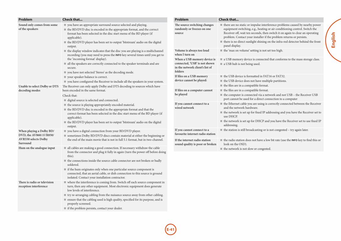
E-41
Eng
lish
Problem Check that...Sound only comes from some of the speakers
< you have an appropriate surround source selected and playing. < the BD/DVD disc is encoded in the appropriate format, and the correct format has been selected in the disc start menu of the BD player (if applicable). < the BD/DVD player has been set to output ‘bitstream’ audio on the digital output. < the display window indicates that the disc you are playing is a multichannel recording (you may need to press the INFO key several times until you get to the ‘incoming format’ display). < all the speakers are correctly connected to the speaker terminals and are secure. < you have not selected ‘Stereo’ as the decoding mode. < your speaker balance is correct. < you have configured the Receiver to include all the speakers in your system.
Unable to select Dolby or DTS decoding modes
The Receiver can only apply Dolby and DTS decoding to sources which have been encoded in the same format.
Check that: < digital source is selected and connected. < the source is playing appropriately encoded material. < the BD/DVD disc is encoded in the appropriate format and that the correct format has been selected in the disc start menu of the BD player (if applicable). < the BD/DVD player has been set to output ‘bitstream’ audio on the digital output.
When playing a Dolby BD/DVD, the AV860/AVR850/AVR550 selects Dolby Surround
< you have a digital connection from your BD/DVD player. < sometimes Dolby BD/DVD discs contain material at either the beginning or the end of the main movie that is not in full 5.1 format, but in two-channel.
Hum on the analogue input < all cables are making a good connection. If necessary withdraw the cable from the connector and plug it fully in again (turn the power off before doing this). < the connections inside the source cable connector are not broken or badly soldered. < if the hum originates only when one particular source component is connected, that an aerial cable, or dish connection to this source is ground isolated. Contact your installation contractor.
There is radio or television reception interference
< where the interference is coming from. Switch off each source component in turn, then any other equipment. Most electronic equipment does generate low levels of interference. < try re-arranging cabling from the nuisance source away from other cabling. < ensure that the cabling used is high quality, specified for its purpose, and is properly screened. < if the problem persists, contact your dealer.
Problem Check that...The source switching changes randomly or freezes on one source
< there are no static or impulse interference problems caused by nearby power equipment switching, e.g., heating or air conditioning control. Switch the Receiver off, wait ten seconds, then switch it on again to clear an operating problem. Contact your installer if the problem returns or persists. < there is no direct sunlight shining on the infra-red detector behind the front panel display.
Volume is always too loud when I turn on
< the ‘max on volume’ setting is not set too high.
When a USB memory device is connected, ‘USB’ is not shown in the network client’s list of folders
< a USB memory device is connected that conforms to the mass storage class. < a USB hub is not being used.
If files on a USB memory device cannot be played:
< the USB device is formatted in FAT16 or FAT32. < the USB device does not have multiple partitions. < the files are in a compatible format.
If files on a computer cannot be played
< the files are in a compatible format. < the computer is connected via a network and not USB – the Receiver USB port cannot be used for a direct connection to a computer
If you cannot connect to a wired network
< the Ethernet cable you are using is correctly connected between the Receiver and the network hardware. < the network is set up for fixed IP addressing and you have the Receiver set to use DHCP. < the network is set up for DHCP and you have the Receiver set to use fixed IP addressing.
If you cannot connect to a favourite internet radio station
< the station is still broadcasting or is not congested – try again later.
If the internet radio station sound quality is poor or broken
< the radio station does not have a low bit rate (use the INFO key to find this or look on the OSD). < the network is not slow or congested.
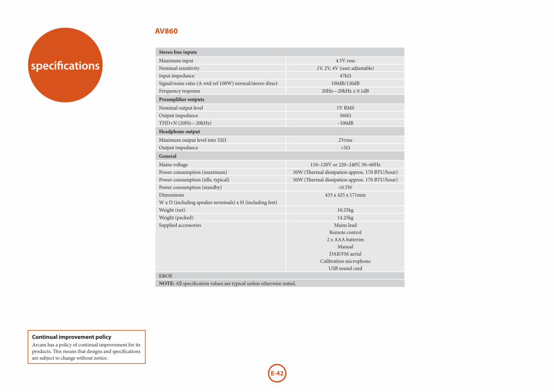
E-42
Continual improvement policyArcam has a policy of continual improvement for its products. This means that designs and specifications are subject to change without notice.
specifications
AV860
Stereo line inputs
Maximum input 4.5V rmsNominal sensitivity 1V, 2V, 4V (user adjustable)Input impedance 47kΩSignal/noise ratio (A-wtd ref 100W) normal/stereo direct 100dB/120dBFrequency response 20Hz—20kHz ± 0.1dB
Preamplifier outputs
Nominal output level 1V RMSOutput impedance 560ΩTHD+N (20Hz—20kHz) –100dB
Headphone output
Maximum output level into 32Ω 2VrmsOutput impedance <5Ω
General
Mains voltage 110–120V or 220–240V, 50 –60HzPower consumption (maximum) 50W (Thermal dissipation approx. 170 BTU/hour)Power consumption (idle, typical) 50W (Thermal dissipation approx. 170 BTU/hour)Power consumption (standby) <0.5WDimensions W x D (including speaker terminals) x H (including feet)
433 x 425 x 171mm
Weight (net) 10.25kgWeight (packed) 14.25kgSupplied accessories Mains lead
Remote control2 x AAA batteries
ManualDAB/FM aerial
Calibration microphoneUSB sound card
E&OENOTE: All specification values are typical unless otherwise stated.
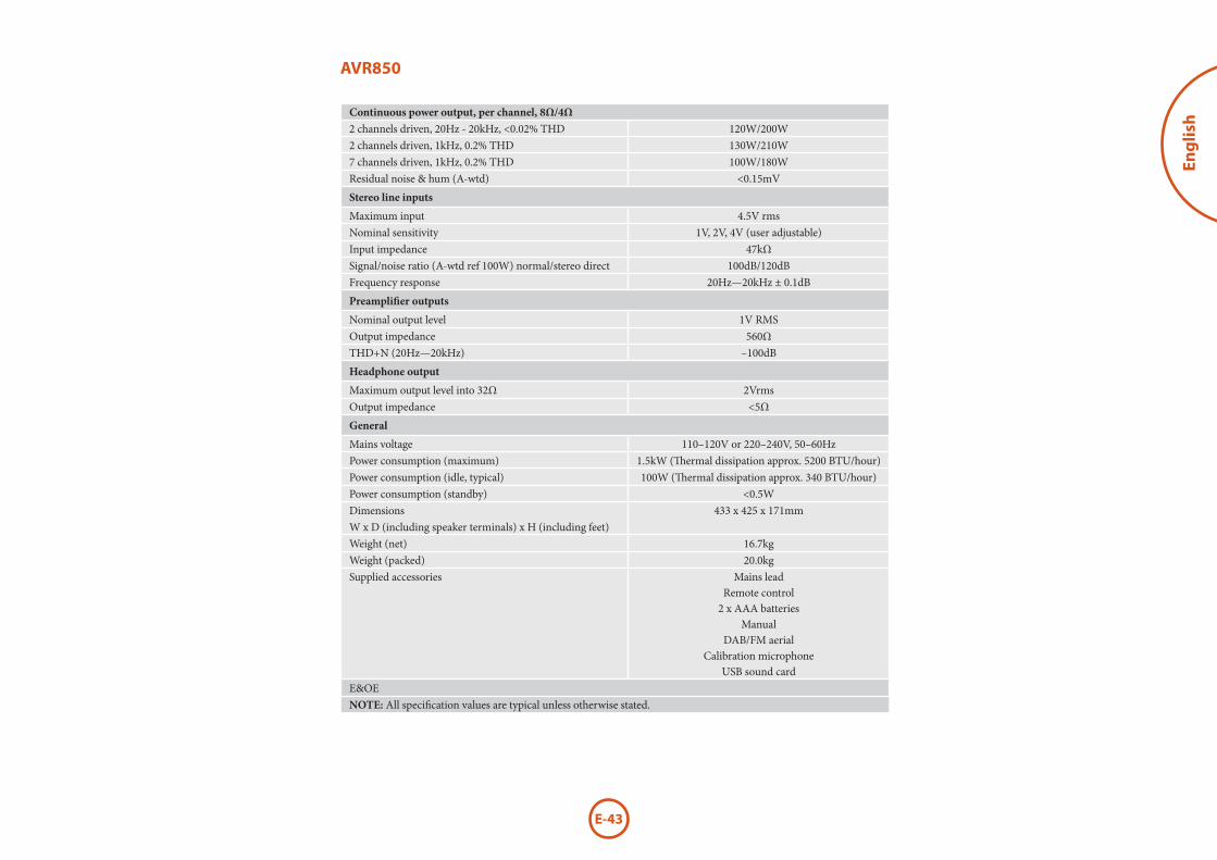
E-43
Eng
lish
AVR850
Continuous power output, per channel, 8Ω/4Ω 2 channels driven, 20Hz - 20kHz, <0.02% THD 120W/200W2 channels driven, 1kHz, 0.2% THD 130W/210W7 channels driven, 1kHz, 0.2% THD 100W/180WResidual noise & hum (A-wtd) <0.15mV
Stereo line inputs
Maximum input 4.5V rmsNominal sensitivity 1V, 2V, 4V (user adjustable)Input impedance 47kΩSignal/noise ratio (A-wtd ref 100W) normal/stereo direct 100dB/120dBFrequency response 20Hz—20kHz ± 0.1dB
Preamplifier outputs
Nominal output level 1V RMSOutput impedance 560ΩTHD+N (20Hz—20kHz) –100dB
Headphone output
Maximum output level into 32Ω 2VrmsOutput impedance <5Ω
General
Mains voltage 110–120V or 220–240V, 50 –60HzPower consumption (maximum) 1.5kW (Thermal dissipation approx. 5200 BTU/hour)Power consumption (idle, typical) 100W (Thermal dissipation approx. 340 BTU/hour)Power consumption (standby) <0.5WDimensions W x D (including speaker terminals) x H (including feet)
433 x 425 x 171mm
Weight (net) 16.7kgWeight (packed) 20.0kgSupplied accessories Mains lead
Remote control2 x AAA batteries
ManualDAB/FM aerial
Calibration microphoneUSB sound card
E&OENOTE: All specification values are typical unless otherwise stated.
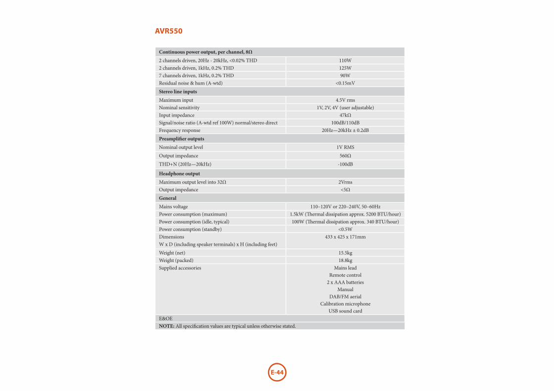
E-44
AVR550
Continuous power output, per channel, 8Ω
2 channels driven, 20Hz - 20kHz, <0.02% THD 110W2 channels driven, 1kHz, 0.2% THD 125W7 channels driven, 1kHz, 0.2% THD 90WResidual noise & hum (A-wtd) <0.15mV
Stereo line inputs
Maximum input 4.5V rmsNominal sensitivity 1V, 2V, 4V (user adjustable)Input impedance 47kΩSignal/noise ratio (A-wtd ref 100W) normal/stereo direct 100dB/110dBFrequency response 20Hz—20kHz ± 0.2dB
Preamplifier outputs
Nominal output level 1V RMS
Output impedance 560Ω
THD+N (20Hz—20kHz) -100dB
Headphone output
Maximum output level into 32Ω 2VrmsOutput impedance <5Ω
General
Mains voltage 110–120V or 220–240V, 50 –60HzPower consumption (maximum) 1.5kW (Thermal dissipation approx. 5200 BTU/hour)Power consumption (idle, typical) 100W (Thermal dissipation approx. 340 BTU/hour)Power consumption (standby) <0.5WDimensions W x D (including speaker terminals) x H (including feet)
433 x 425 x 171mm
Weight (net) 15.5kgWeight (packed) 18.8kgSupplied accessories Mains lead
Remote control2 x AAA batteries
ManualDAB/FM aerial
Calibration microphoneUSB sound card
E&OENOTE: All specification values are typical unless otherwise stated.

E-45
Eng
lish
AVR390
Continuous power output, per channel, 8Ω
2 channels driven, 20Hz - 20kHz, <0.02% THD 80W2 channels driven, 1kHz, 0.2% THD 86W7 channels driven, 1kHz, 0.2% THD 60WResidual noise & hum (A-wtd) <0.15mV
Stereo line inputs
Maximum input 4.5V rmsNominal sensitivity 1V, 2V, 4V (user adjustable)Input impedance 47kΩSignal/noise ratio (A-wtd ref 100W) normal/stereo direct 100dB/110dBFrequency response 20Hz—20kHz ± 0.2dB
Preamplifier outputs
Nominal output level 1V RMS
Output impedance 560Ω
THD+N (20Hz—20kHz) -100dB
Headphone output
Maximum output level into 32Ω 2VrmsOutput impedance <5Ω
General
Mains voltage 110–120V or 220–240V, 50 –60HzPower consumption (maximum) 1.5kW (Thermal dissipation approx. 5200 BTU/hour)Power consumption (idle, typical) 100W (Thermal dissipation approx. 340 BTU/hour)Power consumption (standby) <0.5WDimensions W x D (including speaker terminals) x H (including feet)
433 x 425 x 171mm
Weight (net) 15.7kgWeight (packed) 19.9kgSupplied accessories Mains lead
Remote control2 x AAA batteries
ManualDAB/FM aerial
Calibration microphoneUSB sound card
E&OENOTE: All specification values are typical unless otherwise stated.

E-46
SR250
Continuous power output, per channel, 8Ω
2 channels driven, 20Hz - 20kHz, <0.02% THD 90W2 channels driven, 1kHz, 0.2% THD 125WResidual noise & hum (A-wtd) <0.15mV
Stereo line inputs
Maximum input 4.5V rmsNominal sensitivity 1V, 2V, 4V (user adjustable)Input impedance 47kΩSignal/noise ratio (A-wtd ref 95W) normal/stereo direct 100dB/110dBFrequency response 20Hz—20kHz ± 0.2dB
Preamplifier outputs
Nominal output level 1V RMSOutput impedance 560ΩTHD+N (20Hz—20kHz) -100dB
Headphone output
Maximum output level into 32Ω 2VrmsOutput impedance <5Ω
General
Mains voltage 110–120V or 220–240V, 50 –60HzPower consumption (maximum) 600W (Thermal dissipation approx. 2040 BTU/hour)Power consumption (idle, typical) 100W (Thermal dissipation approx. 340 BTU/hour)Power consumption (standby) <0.5WDimensions W x D (including speaker terminals) x H (including feet)
433 x 425 x 171mm
Weight (net) 15.1kgWeight (packed) 18.5kgSupplied accessories Mains lead
Remote control2 x AAA batteries
ManualFM aerial
Calibration microphoneUSB sound card
E&OENOTE: All specification values are typical unless otherwise stated.

E-47
Eng
lishproduct
guarantee
Worldwide GuaranteeThis entitles you to have the unit repaired free of charge, during the first two years after purchase, provided that it was originally purchased from an authorised Arcam dealer. The Arcam dealer is responsible for all after-sales service. The manufacturer can take no responsibility for defects arising from accident, misuse, abuse, wear and tear, neglect or through unauthorised adjustment and/or repair, neither can they accept responsibility for damage or loss occurring during transit to or from the person claiming under the guarantee.
The warranty covers:Parts and labour costs for two years from the purchase date. After two years you must pay for both parts and labour costs. The warranty does not cover transportation costs at any time.
Claims under guaranteeThis equipment should be packed in the original packing and returned to the dealer from whom it was purchased. It should be sent carriage prepaid by a reputable carrier – not by post. No responsibility can be accepted for the unit whilst in transit to the dealer or distributor and customers are therefore advised to insure the unit against loss or damage whilst in transit.
For further details contact Arcam at [email protected]
Problems?If your Arcam dealer is unable to answer any query regarding this or any other Arcam product please contact Arcam Customer Support at the above address and we will do our best to help you.
On-line registrationYou can register your product on-line at www.arcam.co.uk.
legal information