available online journal of scientific and...
TRANSCRIPT
Available online www.jsaer.com
Journal of Scientific and Engineering Research
319
Journal of Scientific and Engineering Research, 2017, 4(9):319-330
Research Article
ISSN: 2394-2630
CODEN(USA): JSERBR
Comparison of DBA vs. DBF by Explanation of Design Characteristics of Hyperbaric
Oxygen Chamber
Tahir ALTINBALIKa*, Tolga KABAK
b
aTrakya University, Engineering Faculty, Mechanical Engineering Department, Edirne / TURKEY
bBaroks Hyperbaric Technology, İstanbul / TURKEY
Abstract Pressure vessel cylinders find wide applications in many areas such as thermal and nuclear power
plants, process and chemical industries, and hyperbaric oxygen therapy chamber. A hyperbaric chamber is a
specific pressure vessel. A hyperbaric oxygen chamber is designed to meet a number of criteria regarding safety
and ease of use. In human medicine, HBOT (Hyperbaric Oxygen Therapy) is most widely known for the
treatment of decompression sickness for divers and more recently for a variety of medical conditions.The
objective of this research work is to compare the design of the HBO cabin for divers, using two approaches
called „design by analysis‟ (DBA) and „design by formula‟ (DBF). For this purpose determination of sheet
thickness of 5 main and important parts of a chamber was performed. These are, main body, torispherical head,
doors, medical lock outside wall and porthole flange. Firstly, the required material thicknesses were calculated
by the empirical formulas according to AD 2000 Merkblatt pressured vessels standard and then results were
examined by the SolidWorks analysis module. AD2000 MB formulas include high safety factors. Then, the
SolidWorks analysis was repeated with the safety factor of 3 and the new sheet thickness values for the chosen
parts were determined. Finally, cost analysis was done. It is shown that the thicknesses suggested by authors are
more reliable than those presented numerically. For material thicknesses suggested by authors, weight and the
total cost of the HBO chamber has been reduced by %55.
Keywords Algorithm, differential equations, nonlinear, two-step
1. Introduction
Engineering design is the process by which engineers‟ intellect, creativity, and knowledge are translated into
useful engineering products that satisfy particular functional requirements and meet engineering specifications
while complying with all constraints. The traditional design approach has been one of deterministic problem
solving, typically involving efforts to meet functional requirements subject to various technical specifications
and economic constraints, among others [1].
Imagining power plants, chemical processing units and many other manufacturing facilities without pressure
vessels is difficult. Pressure vessel cylinders find wide applications in thermal and nuclear power plants, hot
water storage tanks, process and chemical industries, hyperbaric oxygen therapy chamber for humans and pets,
in space and ocean depths, and fluid supply systems in industries [2]. Industrial pressure vessels are usually
structures with complex geometry containing numerous geometrical discontinuities and are often required to
perform under complex loading conditions such as internal pressure, external forces, thermal loads, etc. [3].
Pressure vessels can theoretically be almost any shape, but shapes made of sections of spheres, cylinders, and
cones are usually employed.Pressure vessel design has been historically based on Design by Formula. Standard
vessel configurations are designed using a series of simple formulae and charts. Many pressure vessel in the
process industry in the world is designed according to ASME Section VIII, Division 1 or AD2000 Merkblatt

ALTINBALIK T & KABAK T Journal of Scientific and Engineering Research, 2017, 4(9):319-330
Journal of Scientific and Engineering Research
320
standards, better known as the “design by rule” or “design by formula” approach. Unfortunately, this approach
has its own problems because the empirical relations developed are primarily based on experience, simple
mechanics and assume large factors of safety. It should be noted that large safety factors lead to increasing the
material thickness, while safety is not necessarily increased; recall that fracture toughness decreases with
increasing thickness, and stress corrosion cracking at components operating in corrosive environments is
expected to be higher in thicker parts [4]. After 2000, finite element analysis (FEA) was included as a standard
practice in most of pressure vessels design codes. Nowadays in addition to the Design by Formula route, many
national codes and standards for pressure vessel and boiler design, also provide for a Design by Analysis route.
Using the design by analysis, the designer is able to calculate stresses everywhere in the vessel. DBA procedures
do not specify particular implementation tools. However, the most widely used technique in contemporary
pressure vessel design is the finite element method (FEM), a powerful technique allowing the detailed
modelling of complex vessels [5].
The design of pressure vessels for operation at high pressures is a complex problem, so finite element methods
are the most frequently used because finite element analysis offers a great deal of promise over other approaches
mainly experimental, in the sense of low cost, high speed, complete information, and ability to simulate realistic
and ideal conditions [6]. Finite element analysis (FEA) utilizing the commercial software packages will be more
appropriate for shell structures involving elements of arbitrary thickness and curvature to obtain the stress
distribution around discontinuities [7]. Finite element method (FEM) is currently one of the most common
numerical methods used for simulations in mechanical engineering. Modern software systems usually allow
using FEM, which enables solving mathematically difficult and time-consuming operations in a meantime. The
basic idea of the FEM is simple, as it requires splitting the solution area to a finite number of sub areas -
elements. These elements are called finite elements. Density of the network fundamentally affects the quality of
the results and amount of used computer memory Finite element analysis (FEA) utilizing the commercial
software packages (ANSYS, SolidWorks, MARC, etc.) will be more appropriate for shell structures involving
elements of arbitrary thickness and curvature to obtain the stress distribution around discontinuities [8].
Yeom [9] investigated the behaviour of pressure vessels with ellipsoidal and torispherical heads under internal
pressure loading. The head thickness was assumed to be equal to the thickness of the cylinder and the
investigation was carried out by finite element analysis and lower bound limit analysis. Wilczynski[10]
numerically determined by means of FEM an optimal shape of thin elastic shells of revolution loaded by internal
pressure. Kedziora and Kubiak [11], using FEM, numerically calculated the stress distribution in pressure tanks.
Widera and Wei [12] presented a finite element model for the analysis of thin shell intersections with large
diameter ratio. Petrovic [13] investigated and determined the influence of forces that can act on a nozzle, in a
cylindrical pressure vessel. In the mentioned study, the FEM applied to determine the state of stress in the
cylindrical shell. Diamantoudis and Kermanidis [14] compared the design of pressure vessels of high strength
steel P500 with the steel alloy P355 using the rules of DBA and DBF. Gross plastic deformation loads were
evaluated for two sample torispherical heads by 2D and 3D FEA based on an elastic-perfectly plastic material
model by Mackenzie et al [15]. Gong et al. [16] performed a finite element analysis of open top tanks and
explained that the structure parameters of top stiffening rings play a significant role on the failure of the
tank.Finite element analysis (FEA) has been carried out using ANSYS software package with 2D axisymmetric
model to access the failure pressure of cylindrical pressure vessel made of ASTM A36 carbon steel having
weld-induced residual stresses by Jeyakumar and Christopher [17]. Three 2-D axisymmetric finite element
models with different vessel radii were constructed and analysed by Lu et al. [18]. Al-Gahtani et al. [19]
presented the findings of a finite element study of the effect of cap size on the stresses near the junction of a
cylindrical nozzle with a spherical vessel under internal pressure. Murtaza [20] aimed to compare the design of
the RPV, using two approaches called „design by analysis‟ (DBA) and „design by formula‟ (DBF). Altınbalık
and Kabak [21] discussed the use of stainless steel instead of pressure vessel steel P275 GH by means of cost
and weight analysis. In the mentioned study the required sheet thickness calculated by the empirical formulas
according to AD 2000 pressured vessels standard and then results examined by the SolidWorks analysis module.
In another study, Altınbalık and Kabak [22] performed the design of penetrator parts and determination of sheet
ALTINBALIK T & KABAK T Journal of Scientific and Engineering Research, 2017, 4(9):319-330
Journal of Scientific and Engineering Research
321
thickness for a hyperbaric diver chamber by means of the AD 2000 pressured vessels standard and SolidWorks.
SolidWorks simulation is a software that allows the use of finite element analysis FEA.
A pressure vessel can be designed using the rules of „design by formula‟ and „design by analysis. The objective
of this research work is to compare the design of a HBO chamber for divers using the two approaches called
DBA and DBF. First, the sheet thicknesses for selected parts of a hyperbaric chamber were calculated by the
empirical formulas according to AD 2000 pressured vessels standard and then results were examined by the
SolidWorks analysis module. The SolidWorks analysis was performed again the whole selected parts with the
safety factor of 3 and the new sheet thickness values for the mentioned parts were determined. Finally, cost
analysis was done.
2. Pressure Chamber for Divers
Hyperbaric oxygen therapy (HBOT) is defined as delivery of 100% oxygen at pressures about one-and-a-half to
three times that of the normal atmosphere while the patient is placed and being pressurised in a chamber. HBOT
is increasingly being recognised as an important adjunct in a select group of indications for which there is
mounting scientific evidence [23]. Hyperbaric oxygen chambers for divers are used on land and above the water
to take surface supplied divers who have been brought up from underwater through their remaining
decompression as surface decompression either after an ambient pressure ascent or after transfer under pressure
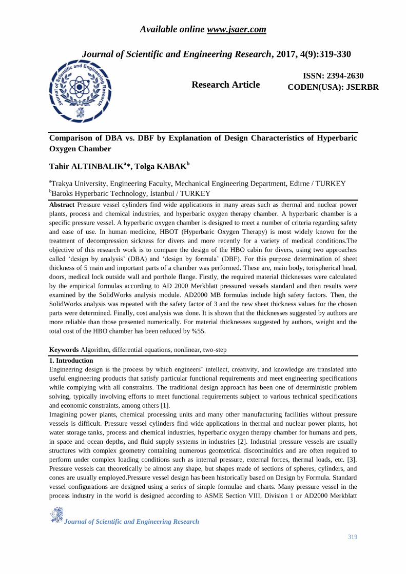
from a dry bell. In this study, asix person multiplace hyperbaric cabin was chosen to carry out analysis as shown
in Fig.1. The cabin operation pressure is 5.94 Bar. Designed parts are also shown clearly in the figures. Several
materials have been used for the penetrators. The flow stresses of the materials and the other specifications for
selected parts of the cabin were given in detailed as seen below.
Figure 1: Schematic view of multiplace hyperbaric chamber
3. Theoretical Calculations
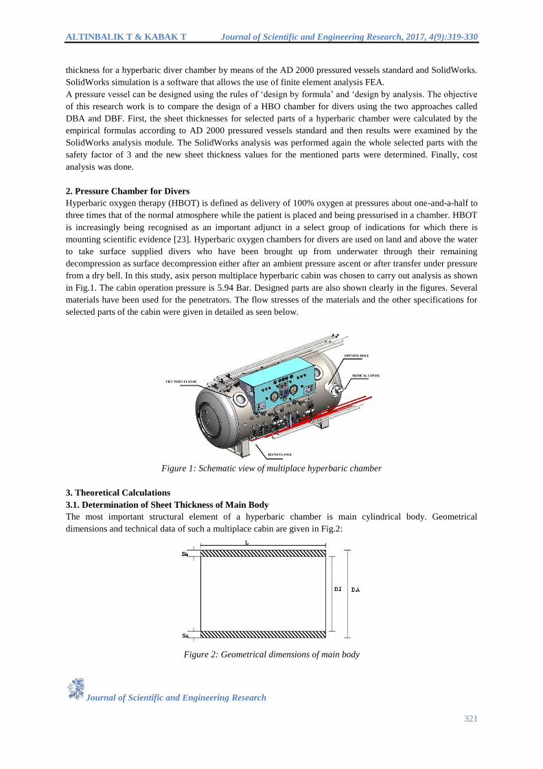
3.1. Determination of Sheet Thickness of Main Body
The most important structural element of a hyperbaric chamber is main cylindrical body. Geometrical
dimensions and technical data of such a multiplace cabin are given in Fig.2:
Figure 2: Geometrical dimensions of main body

ALTINBALIK T & KABAK T Journal of Scientific and Engineering Research, 2017, 4(9):319-330
Journal of Scientific and Engineering Research
322
Necessary Nomenclature
P = 5.94 bar (Maximum Allowable Pressure)
Da= 1524 mm (Outer diameter of the main body)
Di= 1504 mm (Inner diameter of the main body)
K = 330 N/mm2(P355GH EN 10028-2)
V = 0.8 (welding factor)
s = 1.7(safety factor)
C1= 0.5 mm(Tolerance factor)
C2= 3 mm (Corrosion factor)
Although there are different formulas for determining the sheet thickness of main body in order to AD 2000
MERKBLATT standard the thickness is determined as below:
21
20
CC
PVs
K
PDS a
t
(1)
mmSt 4.635.094.53106
56.905235.0
94.58.07.1
33020
94.51524
Although the formula gives us this thickness value, the thickness of the head must also be determined in order to
determine the main body thickness. Thus, it is intended that the main body and the head are compatible. The
head thickness is chosen as 10 mm as seen in the calculations below. Then, 10 mm. sheet thickness is also
chosen for main body.
3.2. Thickness Calculation of Outside Torispherical Head
These heads have a dish with a fixed radius (r1), the size of which depends on the type of torispherical head. The
transition between the cylinder and the dish is called the knuckle. The knuckle has a toroidal shape. In this study
torispherical head was designed according to Klöpper type head geometrical dimensions as shown in Fig.3
(R=Da , r=0.1Da and h2=0.1935Da-0.455Se ).
Figure 3: Geometrical dimensions of torispherical head
Necessary Nomenclature
S: (Calculated torispherical head thickness)
eS : (Instant torispherical head thickness)
K = 330 N/mm2 (P355GH EN 10028-2)
ß: (Design factor)
a
e
D
CCS 21 (2)
As explained detailed in the previous work of authors [24] a predictor-corrector cycle is performed for the
determination of the sheet thickness of the outside torispherical head. First operation of calculation is to predict
Se value and insert it into the equation 2, and the β corresponding to the Se value in the graph which given in ref
[24]is read. After that, the S value is calculated by inserting β into the equation 3. Assuming the calculated S
ALTINBALIK T & KABAK T Journal of Scientific and Engineering Research, 2017, 4(9):319-330
Journal of Scientific and Engineering Research
323
value as Se, it is again inserted into the equation 2 and a predictor-corrector cycle is performed. This iteration is
continued until the difference between the allowable value and final value becomes less than 0.1.
First Iteration: mmSe 10 is selected
0043.01524
35.01021
a
e
D
CCS 4.3
𝑆 =𝐷𝑥𝑃𝑥𝛽
40𝑥𝐾𝑥𝑉
𝑠
+ 𝐶1 + 𝐶2 (3)
mmS 95.835.0
8.07.1
33040
4.394.51524
After the 2nd
iteration S=8.82 mm is obtained and this value inserted in Eq.2 as Se. Then S=8.89 mm. is obtained
and 10 mm. sheet thickness is chosen as standard product.
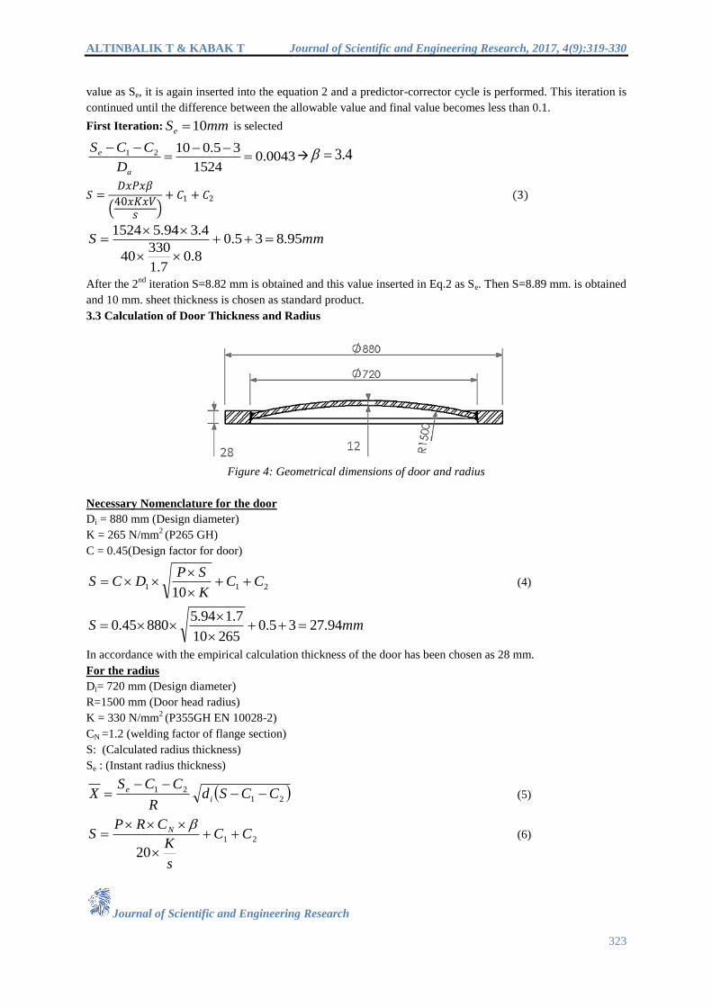
3.3 Calculation of Door Thickness and Radius
Figure 4: Geometrical dimensions of door and radius
Necessary Nomenclature for the door
Di = 880 mm (Design diameter)
K = 265 N/mm2 (P265 GH)
C = 0.45(Design factor for door)
21110
CCK
SPDCS
(4)
mmS 94.2735.026510
7.194.588045.0
In accordance with the empirical calculation thickness of the door has been chosen as 28 mm.
For the radius
Di= 720 mm (Design diameter)
R=1500 mm (Door head radius)
K = 330 N/mm2 (P355GH EN 10028-2)
CN =1.2 (welding factor of flange section)
S: (Calculated radius thickness)
Se : (Instant radius thickness)
21
21 CCSdR
CCSX i
e
(5)
21
20
CC
s
K
CRPS N
(6)
ALTINBALIK T & KABAK T Journal of Scientific and Engineering Research, 2017, 4(9):319-330
Journal of Scientific and Engineering Research
324
Similar to outside torispherical head calculation first operation of calculation is to predict Se value and insert it
into the equation 5, and the β corresponding to the Se value in the graph is read. The next calculation steps are
same as the described above for torispherical head.
First Iteration: mmSe 10 is selected
296.035.0107201500
35.010
X
65.2
mmCC
s
K
CRPS N 8.1035.0
7.1
33020
65.22.1150094.5
2021
After the 2nd
iteration the difference between the allowable value and final value becomes less than 0.1 and is
obtained as S=10.72 mm. The radius is chosen as 12 mm.
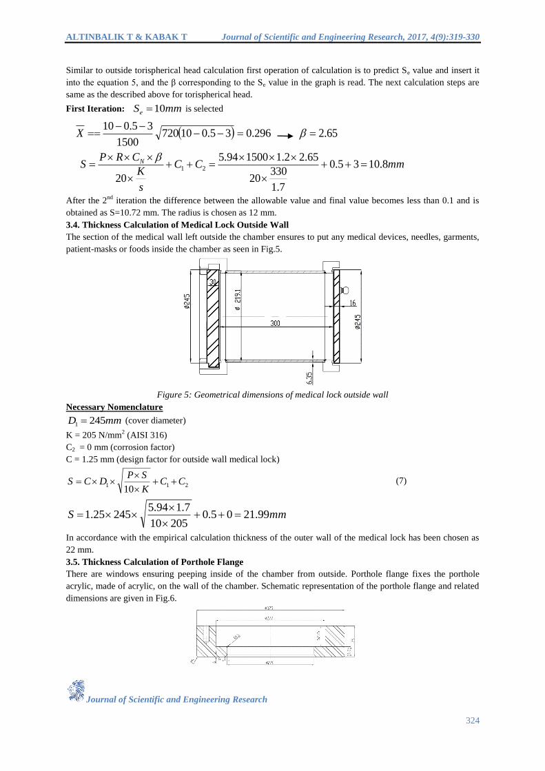
3.4. Thickness Calculation of Medical Lock Outside Wall
The section of the medical wall left outside the chamber ensures to put any medical devices, needles, garments,
patient-masks or foods inside the chamber as seen in Fig.5.
Figure 5: Geometrical dimensions of medical lock outside wall
Necessary Nomenclature
mmD 2451 (cover diameter)
K = 205 N/mm2 (AISI 316)
C2 = 0 mm (corrosion factor)
C = 1.25 mm (design factor for outside wall medical lock)
21110
CCK
SPDCS
(7)
mmS 99.2105.020510
7.194.524525.1
In accordance with the empirical calculation thickness of the outer wall of the medical lock has been chosen as
22 mm.
3.5. Thickness Calculation of Porthole Flange
There are windows ensuring peeping inside of the chamber from outside. Porthole flange fixes the porthole
acrylic, made of acrylic, on the wall of the chamber. Schematic representation of the porthole flange and related
dimensions are given in Fig.6.
ALTINBALIK T & KABAK T Journal of Scientific and Engineering Research, 2017, 4(9):319-330
Journal of Scientific and Engineering Research
325
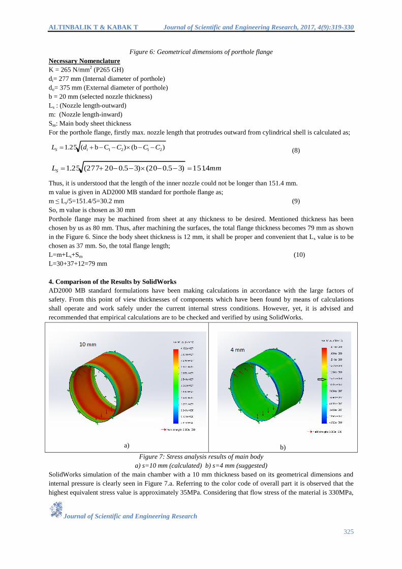
Figure 6: Geometrical dimensions of porthole flange
Necessary Nomenclature
K = 265 N/mm2 (P265 GH)
di= 277 mm (Internal diameter of porthole)
do= 375 mm (External diameter of porthole)
b = 20 mm (selected nozzle thickness)
Ls : (Nozzle length-outward)
m: (Nozzle length-inward)
Sm: Main body sheet thickness
For the porthole flange, firstly max. nozzle length that protrudes outward from cylindrical shell is calculated as;
)b()Cb(25.1 2121 CCCdL iS (8)
mmLS 4.151)35.020()35.020277(25.1
Thus, it is understood that the length of the inner nozzle could not be longer than 151.4 mm.
m value is given in AD2000 MB standard for porthole flange as;
m ≤ Ls/5=151.4/5=30.2 mm (9)
So, m value is chosen as 30 mm
Porthole flange may be machined from sheet at any thickness to be desired. Mentioned thickness has been
chosen by us as 80 mm. Thus, after machining the surfaces, the total flange thickness becomes 79 mm as shown
in the Figure 6. Since the body sheet thickness is 12 mm, it shall be proper and convenient that Ls value is to be
chosen as 37 mm. So, the total flange length;
L=m+Ls+Sm (10)
L=30+37+12=79 mm
4. Comparison of the Results by SolidWorks
AD2000 MB standard formulations have been making calculations in accordance with the large factors of
safety. From this point of view thicknesses of components which have been found by means of calculations
shall operate and work safely under the current internal stress conditions. However, yet, it is advised and
recommended that empirical calculations are to be checked and verified by using SolidWorks.
a)
b)
Figure 7: Stress analysis results of main body
a) s=10 mm (calculated) b) s=4 mm (suggested)
SolidWorks simulation of the main chamber with a 10 mm thickness based on its geometrical dimensions and
internal pressure is clearly seen in Figure 7.a. Referring to the color code of overall part it is observed that the
highest equivalent stress value is approximately 35MPa. Considering that flow stress of the material is 330MPa,
ALTINBALIK T & KABAK T Journal of Scientific and Engineering Research, 2017, 4(9):319-330
Journal of Scientific and Engineering Research
326
it can be said that the determined sheet thickness has a safety factor of 9.4. SolidWorks analysis of the chamber
with a 4 mm sheet metal thickness is seen in Figure 7.b. The highest Von-Misses equivalent stress is around
107MPaaccording to color scale and the cabin has a safety factor of approximately 3 under internal pressure.
There is no need to consider the maximum value of the color scale because there is no red region in the color
code on the part. Furthermore, during SolidWorks analyses the maximum allowable pressure value was used but
normally the cabin will be subject to the maximum allowable working pressure. Maximum allowable pressure
(MAP) value is the maximum unit pressure permitted in a given material used in a chamber. Maximum
allowable working pressure (MAWP) for a chamber is the maximum internal or external pressure permissible at
the top of the vessel in its normal operating position. Cabins are not vulnerable to corrosive environments
because sandblasting and painting will be applied to them. Thus, it can be said that a 3 mm corrosion tolerance
is not completely necessary for a hyperbaric diver chamber.
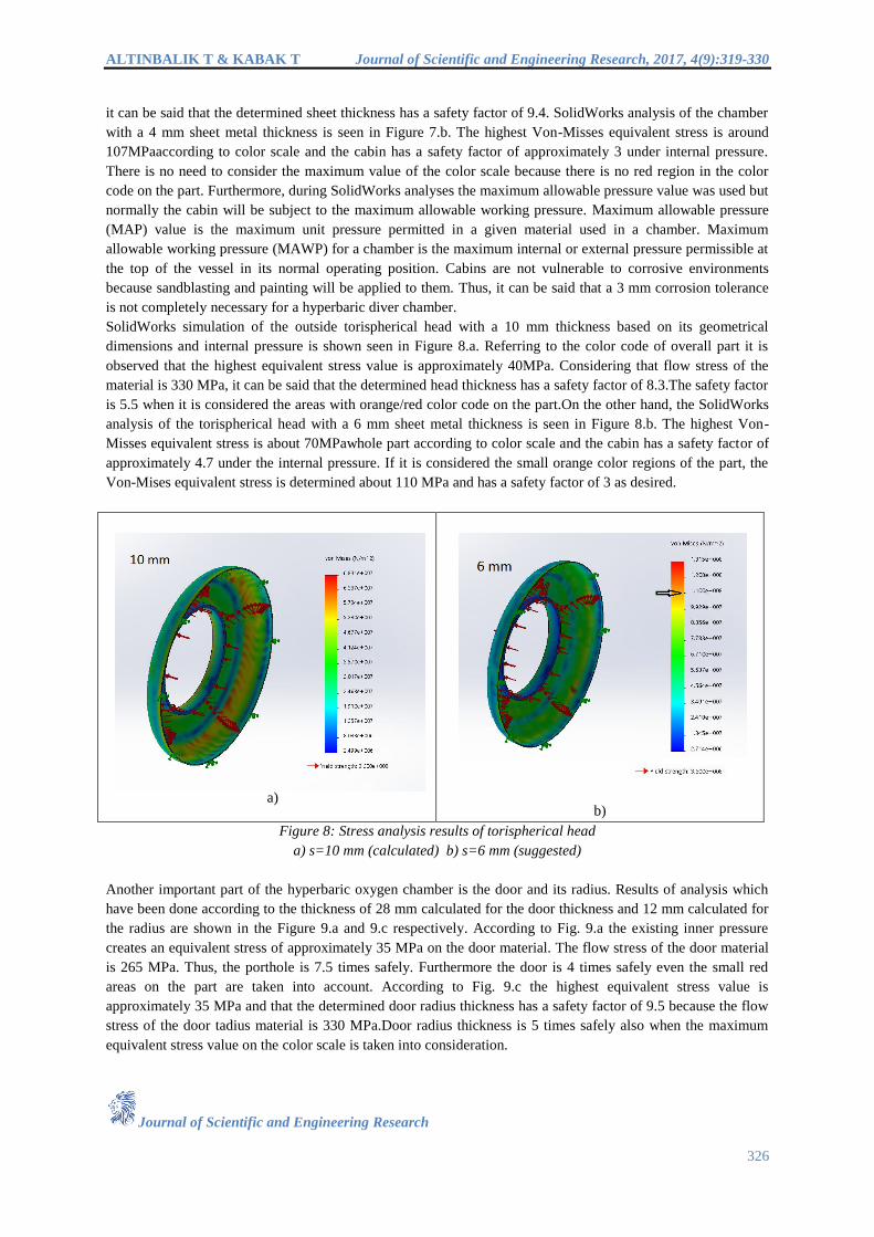
SolidWorks simulation of the outside torispherical head with a 10 mm thickness based on its geometrical
dimensions and internal pressure is shown seen in Figure 8.a. Referring to the color code of overall part it is
observed that the highest equivalent stress value is approximately 40MPa. Considering that flow stress of the
material is 330 MPa, it can be said that the determined head thickness has a safety factor of 8.3.The safety factor
is 5.5 when it is considered the areas with orange/red color code on the part.On the other hand, the SolidWorks
analysis of the torispherical head with a 6 mm sheet metal thickness is seen in Figure 8.b. The highest Von-
Misses equivalent stress is about 70MPawhole part according to color scale and the cabin has a safety factor of
approximately 4.7 under the internal pressure. If it is considered the small orange color regions of the part, the
Von-Mises equivalent stress is determined about 110 MPa and has a safety factor of 3 as desired.
a)
b)
Figure 8: Stress analysis results of torispherical head
a) s=10 mm (calculated) b) s=6 mm (suggested)
Another important part of the hyperbaric oxygen chamber is the door and its radius. Results of analysis which
have been done according to the thickness of 28 mm calculated for the door thickness and 12 mm calculated for
the radius are shown in the Figure 9.a and 9.c respectively. According to Fig. 9.a the existing inner pressure
creates an equivalent stress of approximately 35 MPa on the door material. The flow stress of the door material
is 265 MPa. Thus, the porthole is 7.5 times safely. Furthermore the door is 4 times safely even the small red
areas on the part are taken into account. According to Fig. 9.c the highest equivalent stress value is
approximately 35 MPa and that the determined door radius thickness has a safety factor of 9.5 because the flow
stress of the door tadius material is 330 MPa.Door radius thickness is 5 times safely also when the maximum
equivalent stress value on the color scale is taken into consideration.

ALTINBALIK T & KABAK T Journal of Scientific and Engineering Research, 2017, 4(9):319-330
Journal of Scientific and Engineering Research
327
In Figure 9.b and Figure 9.d it is shown that the SolidWorks analysis in which the maximum equivalent stress is
one third of the yield stress of the door and the door radius material.In Figure 9.b the SolidWorks analysis of the
door with a 18.5 mm sheet metal thickness is seen. Referring to the color code of overall part it is observed that
the highest equivalent stress value is approximately 50MPa. and considering the flow stress of the material is
265MPa, the determined door thickness has a safety factor of 5.3. The safety factor for door material is 3 when
it is considered the areas with red color code on the part as seen in Fig.9.b.
In Figure 9.d. it is seen that the inner pressure creates an equivalent stress of approximately 55 MPa on the door
radius materialof which the thickness is 7 mm. This means that determined thickness according to SolidWorks
analysis is about 6 times safely. If it is considered the small red color regions of the part, the Von-Mises
equivalent stress is determined about 111MPa and has a safety factor of 3 as desired.
a)
b)
c)
d)
Figure 9: Stress analysis results of door and its radius
a) s=28 mm (calculated door thickness) b) s=18.5 mm (suggested door thickness)
c)s=12 mm (calculated door radius) d) s=7 mm (suggested door radius)
The existing stress distribution for the thickness of the wall remained outside the medical lock is shown in
Figure 10.a Calculated thickness value of the medical lock outside wall is 22 mm. When the color scale is
examined it is seen that the maximum equivalent stress value is about 10 MPa. The flow stress of the material
used is 206 MPa, accordingly the wall thickness of the material chosen is approximately 20 times safety. The
SolidWorks analysis of the medical lock outside wall with a 8.5 mm sheet metal thickness is seen in Figure
10.b. The highest Von-Misses equivalent stress is about 40MPawhole part according to color scale and the cabin
has a safety factor of approximately 5 under the internal pressure. If it is considered the small orange/red color
regions of the part, the Von-Mises equivalent stress is determined about 68 MPaand has a safety factor of 3.

ALTINBALIK T & KABAK T Journal of Scientific and Engineering Research, 2017, 4(9):319-330
Journal of Scientific and Engineering Research
328
a)
b)
Figure 10: Stress analysis results of medical lock outside wall
a) s=22 mm (calculated) b) s=8.5 mm (suggested)
Results of analysis which have been done according to the thickness of 79 mm calculated for the porthole flange
are shown in the Figure 11.a. The existing inner pressure creates an equivalent stress of approximately 6 MPa on
the porthole material. The flow stress of the porthole material so chosen is 265 MPa. Thus, the porthole is 44
times safely. If it is considered the outer edge of porthole the equivalent stress is 9.7 MPa and the porthole is 26
times safely. It is possible to reduce the thickness of porthole flange about 35-40 mm but the thickness could be
chosen at least 59 mm. because 40 mm thick acrylic flat disk enters into the porthole flange. In Figure 11.b. the
SolidWorks analysis of the flange with a 59 mm thickness is shown. According to analysis this thickness is at
least 19 times safely because maximum equivalent stress is 14 MPa while flow stress of the material is 265
MPa.
a)
b)
Figure 11: Stress analysis results of porthole flange
a) s=80 mm (calculated) b) s=59 mm (suggested)
5. Weight and Cost Analysis
The main structural parts of a hyperbaric oxygen chamber have a very high safety factor, as can be seen from
the calculated thickness values according to the AD2000 Merkblatt standards. It is also shown in the diagrams
above that the thicknesses of these parts can be determined with the safety factor of 3 with SolidWorks analysis.
Weight values and prices are given in the following table according to results by the DBF and the DBA.
ALTINBALIK T & KABAK T Journal of Scientific and Engineering Research, 2017, 4(9):319-330
Journal of Scientific and Engineering Research
329
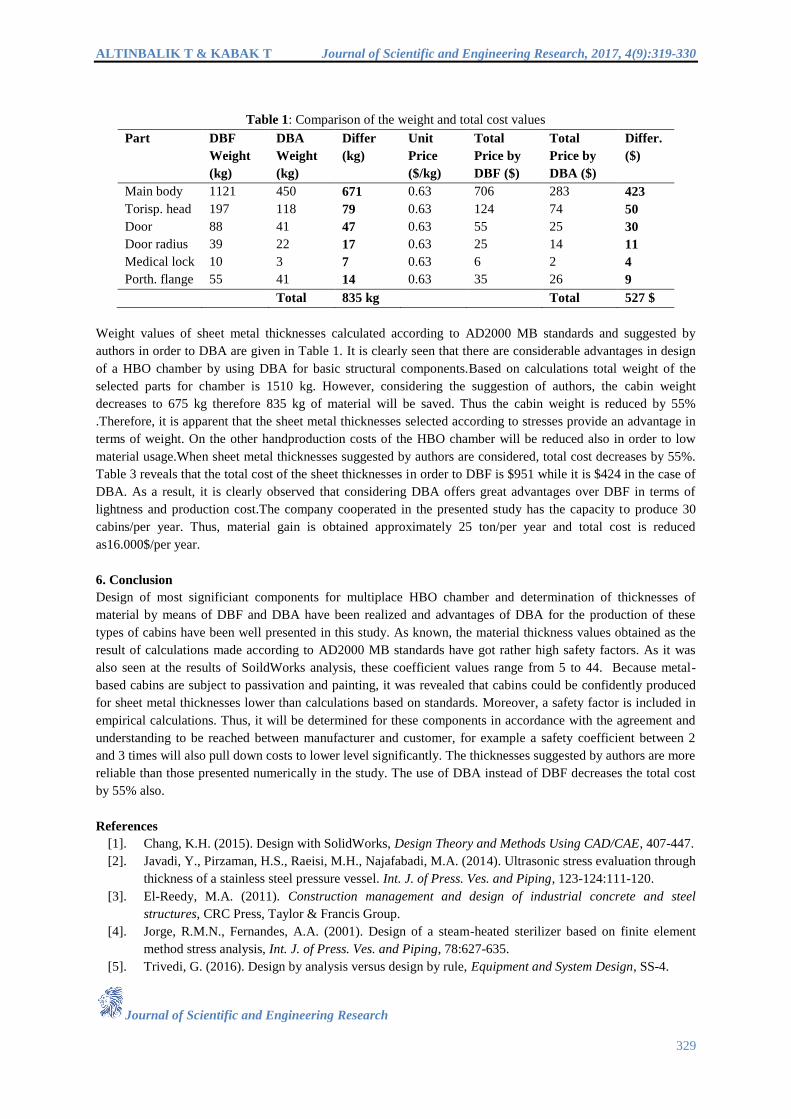
Table 1: Comparison of the weight and total cost values
Part DBF
Weight
(kg)
DBA
Weight
(kg)
Differ
(kg)
Unit
Price
($/kg)
Total
Price by
DBF ($)
Total
Price by
DBA ($)
Differ.
($)
Main body 1121 450 671 0.63 706 283 423
Torisp. head 197 118 79 0.63 124 74 50
Door 88 41 47 0.63 55 25 30
Door radius 39 22 17 0.63 25 14 11
Medical lock 10 3 7 0.63 6 2 4
Porth. flange 55 41 14 0.63 35 26 9
Total 835 kg Total 527 $
Weight values of sheet metal thicknesses calculated according to AD2000 MB standards and suggested by
authors in order to DBA are given in Table 1. It is clearly seen that there are considerable advantages in design
of a HBO chamber by using DBA for basic structural components.Based on calculations total weight of the
selected parts for chamber is 1510 kg. However, considering the suggestion of authors, the cabin weight
decreases to 675 kg therefore 835 kg of material will be saved. Thus the cabin weight is reduced by 55%
.Therefore, it is apparent that the sheet metal thicknesses selected according to stresses provide an advantage in
terms of weight. On the other handproduction costs of the HBO chamber will be reduced also in order to low
material usage.When sheet metal thicknesses suggested by authors are considered, total cost decreases by 55%.
Table 3 reveals that the total cost of the sheet thicknesses in order to DBF is $951 while it is $424 in the case of
DBA. As a result, it is clearly observed that considering DBA offers great advantages over DBF in terms of
lightness and production cost.The company cooperated in the presented study has the capacity to produce 30
cabins/per year. Thus, material gain is obtained approximately 25 ton/per year and total cost is reduced
as16.000$/per year.
6. Conclusion
Design of most significiant components for multiplace HBO chamber and determination of thicknesses of
material by means of DBF and DBA have been realized and advantages of DBA for the production of these
types of cabins have been well presented in this study. As known, the material thickness values obtained as the
result of calculations made according to AD2000 MB standards have got rather high safety factors. As it was
also seen at the results of SoildWorks analysis, these coefficient values range from 5 to 44. Because metal-
based cabins are subject to passivation and painting, it was revealed that cabins could be confidently produced
for sheet metal thicknesses lower than calculations based on standards. Moreover, a safety factor is included in
empirical calculations. Thus, it will be determined for these components in accordance with the agreement and
understanding to be reached between manufacturer and customer, for example a safety coefficient between 2
and 3 times will also pull down costs to lower level significantly. The thicknesses suggested by authors are more
reliable than those presented numerically in the study. The use of DBA instead of DBF decreases the total cost
by 55% also.
References
[1]. Chang, K.H. (2015). Design with SolidWorks, Design Theory and Methods Using CAD/CAE, 407-447.
[2]. Javadi, Y., Pirzaman, H.S., Raeisi, M.H., Najafabadi, M.A. (2014). Ultrasonic stress evaluation through
thickness of a stainless steel pressure vessel. Int. J. of Press. Ves. and Piping, 123-124:111-120.
[3]. El-Reedy, M.A. (2011). Construction management and design of industrial concrete and steel
structures, CRC Press, Taylor & Francis Group.
[4]. Jorge, R.M.N., Fernandes, A.A. (2001). Design of a steam-heated sterilizer based on finite element
method stress analysis, Int. J. of Press. Ves. and Piping, 78:627-635.
[5]. Trivedi, G. (2016). Design by analysis versus design by rule, Equipment and System Design, SS-4.

ALTINBALIK T & KABAK T Journal of Scientific and Engineering Research, 2017, 4(9):319-330
Journal of Scientific and Engineering Research
330
[6]. Middletown, J., Owen, D.R.J. (1977). Automated design optimization to minimize shearing stress in
axisymmetric pressure-vessels, Nuclear Eng and Des., 44(3):357-366.
[7]. Brabin, T.A., Christoper, T., Rao, B.N. (2010). Finite element analysis of cylindrical pressure vessels
having a misalignment in a circumferential joint, Int. J. of Press. Ves. and Piping, 87:197-201.
[8]. Glodova, I., Liptak, T., Bocko, J. (2010). Usage of finite element method for motion and thermal
analysis of a specific object in SolidWorks environment, Procedia Engineering, 96:131-135.
[9]. Yeom, D.J., Robinson, M. (1996). Numerical analysis of the elastic-plastic behaviour of pressure
vessels with ellipsoidal and torispherical heads, Int.J.ofPress.Ves.and Piping, 65:147-156.
[10]. Wilczynski, B. (1998). Shape optimization of thin elastic shell of revolution with axisymmetric
loading, 16th
ConfPoliopt CAD Koszalin, 396-403.
[11]. Kedziora, S., Kubiak, T. (1999). Application of FEM for calculation of stresses and strains in pressure
tanks, Dozor Techniczny, 4:83-85.
[12]. Widera, G., Wei, Z. (1999). Parametric finite element analysis of large diameter ratio shell
intersections subjected to internal pressure, Trans.of the 15th
IntConf on Struc.Mech.in reactor Tech.
SMIRT15, Seoul, 129-136.
[13]. Petrovic, A. (2001). Stress analysis in cylindrical pressure vessel with loads applied to the free end of a
nozzle, Int. J. of Press. Ves. and Piping, 78:485-93.
[14]. Diamantoudis, A. Th., Kermanidis, Th. (2005). Design by analysis versus design by formula of high
strength steel pressure vessels: a comparative study, Int. J. of Press. Ves. and Piping, 82:43-50.
[15]. Mackenzie, D., Camilleri, D., Hamilton, R. (2008). Design by analysis of ductile failure and buckling
in torispherical pressure vessel heads, Thin-Walled Structures, 46:963-974.
[16]. Gong, J., Tao, J., Zhao, J., Zeng, S., Jin, T. (2013). Effect of top stiffening rings of open top tanks on
critical harmonic settlement, Thin-Walled Structures, 65:62–71.
[17]. Jeyakumar, M., Christopher, T. (2013). Influence of residual stresses on failure pressure of cylindrical
pressure vessels, Chinese Journal of Aeronautics, 26(6):1415-1421.
[18]. Lu, M.H., Yu, J.S. and Chen, J.J. (2014). The effect of analysis model on the stress intensity
calculation for the nozzle attached to pressure vessel under internal pressure loading, Int. J. of Press.
Ves. and Piping, 117-118:9-16.
[19]. Al-Gahtani, H., Khathlan, A., Sunar, M., Naffa‟a M. (2014). Local pressure testing of spherical vessels,
Int.J.of Press. Ves. and Piping, 114-115:61-68.
[20]. Murtaza, U.T., Hyder, M.J. (2015). Design by analysis versus design by formula of a PWR reactor
pressure vessel, Proc. of 1the Int Multi Conference of Engineers and Computer Scientist, IMECS 2015,
Hong Kong, 2:942-946.
[21]. Altınbalık, M.T., Kabak, T. (2015). Strength and cost analysis of stainless steel uses in the multiplace
hyperbaric chambers, Proc. of 15th
Int Sci. Conf. UNITECH’15, Gabrovo, 3:137-143.
[22]. Altınbalık, M.T., Kabak, T. (2016). Penetrators design characteristics of a multiplace hyperbaric
chamber for divers, Proc. of 16th
Int Scientific Conf. UNITECH’16, Gabrovo, 3:143-148.
[23]. Verghese, G., Verma, R., Bhutani, S. (2013). Hyperbaric oxygen therapy in the battlefield, Medical J.
Armed Forces India, 69:94-96.
[24]. Altınbalık, T., Kabak, T. (2016). PMMA Usage in a Hyperbaric Pet Chamber: A Contribution to
Design and Comparative Cost Analysis for Different Materials, International Journal of Research in
Engineering and Applied Sciences, 6(7):57-69.