avery alx-924 manual
TRANSCRIPT

09/06 Rev. 3.06-01 OPERATING MANUALALX 92x
Device description, OperationDevice description ......................................... 2
Operating Parts ......................................... 2Connections .............................................. 4Warning notices ........................................ 6Control panel (display) .............................. 7Operating modes ....................................... 8
Basic operating procedures ........................ 10Connecting the device ............................. 10Setting the interface ................................ 11Offline operation ...................................... 12
Online operation ......................................13Creating a print job ..................................13Transferring a print job .............................14Applying CompactFlash cards .................15Setting the realtime clock .........................16Outputting the realtime clock value using Easy Plug .................................................16
The first device test .....................................17Settings for the material type ...................17Printing the status report ..........................17

09/06 Rev. 3.06-01 OPERATING MANUAL Device Description
ALX 92x
2
Device description
Operating Parts
[1] Exterior of the ALX 92x.
Front hoodOpen up to insert ribbon
Control panelLCD display; 4 operating keys; on / off button; displays the de-vice operating status; for defining settings in the parameter menu
Material unwinderUnwinds the label material
Guiding rodPrevents rolls from slipping off the mate-rial unwinder and the backing paper rewin-der
Material dancer armCompensates abrupt movements of the label web
Backing paper rewinderRewinds the remaining backing paper
Backing paper dancer armCompensates abrupt move-ments of the backing paper web
WindowFor checking the ribbon supply without opening the front cover
Printhead
Pre-drilled holes forassembling the
applicatorAssembly of the pivot
unit for the applicatorsLTSI, LTP or LTPV
09/06 Rev. 3.06-01 OPERATING MANUAL Device Description
ALX 92x
3
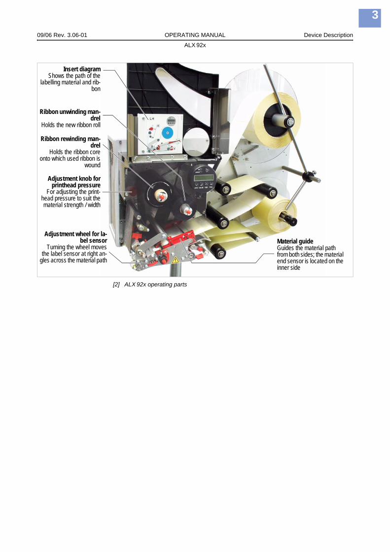
[2] ALX 92x operating parts
Insert diagramShows the path of the
labelling material and rib-bon
Adjustment knob forprinthead pressure
For adjusting the print-head pressure to suit thematerial strength / width
Ribbon rewinding man-drel
Holds the ribbon coreonto which used ribbon is
wound
Ribbon unwinding man-drel
Holds the new ribbon roll
Adjustment wheel for la-bel sensor
Turning the wheel movesthe label sensor at right an-
gles across the material path
Material guideGuides the material path from both sides; the material end sensor is located on the inner side

09/06 Rev. 3.06-01 OPERATING MANUAL Device Description
ALX 92x
4
Connections
[3] Connections at the ALX 92x (RH).
CAUTION! - Additional devices of inadequate quality can damage the device!
Connect the device only to devices that fulfil SELV (safety extra-low voltage) circuit requirements acc. to EN 60950!Only connect OEM devices.
B
A
C
D
E
F
H
G
J
K
L
N
O
M
I
09/06 Rev. 3.06-01 OPERATING MANUAL Device Description
ALX 92x
5
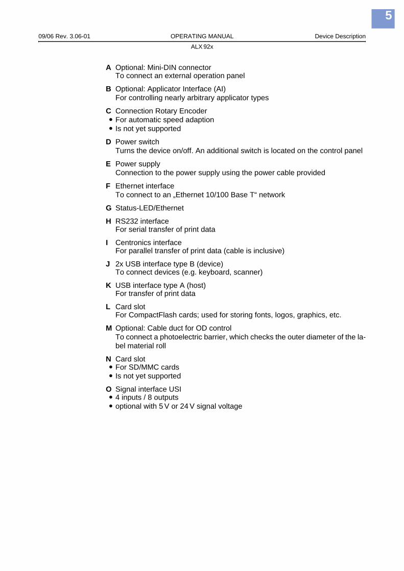
A Optional: Mini-DIN connectorTo connect an external operation panel
B Optional: Applicator Interface (AI)For controlling nearly arbitrary applicator types
C Connection Rotary EncoderFor automatic speed adaptionIs not yet supported
D Power switchTurns the device on/off. An additional switch is located on the control panel
E Power supplyConnection to the power supply using the power cable provided
F Ethernet interfaceTo connect to an „Ethernet 10/100 Base T“ network
G Status-LED/Ethernet
H RS232 interfaceFor serial transfer of print data
I Centronics interfaceFor parallel transfer of print data (cable is inclusive)
J 2x USB interface type B (device)To connect devices (e.g. keyboard, scanner)
K USB interface type A (host)For transfer of print data
L Card slotFor CompactFlash cards; used for storing fonts, logos, graphics, etc.
M Optional: Cable duct for OD controlTo connect a photoelectric barrier, which checks the outer diameter of the la-bel material roll
N Card slotFor SD/MMC cardsIs not yet supported
O Signal interface USI4 inputs / 8 outputsoptional with 5 V or 24 V signal voltage

09/06 Rev. 3.06-01 OPERATING MANUAL Device Description
ALX 92x
6
Warning notices
[4] Warning notice on the ALX 92x
The label depicted at [4] warns against the danger of being caught in the moving parts of the device.
Warning labels must be replaced if they are lost or become illegible (part nr. A5346).
WARNING!
Keep hands clearof rollers.
A5346
09/06 Rev. 3.06-01 OPERATING MANUAL Device Description
ALX 92x
7
Control panel (display)
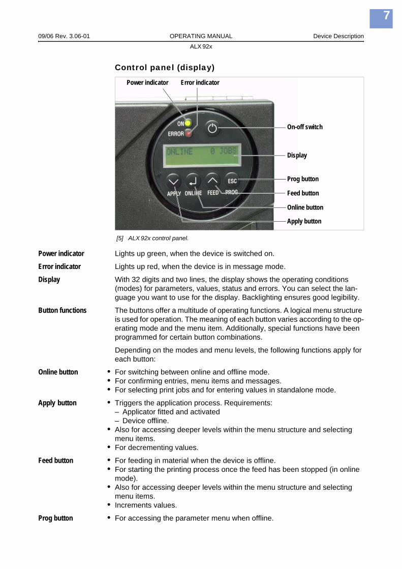
[5] ALX 92x control panel.
Power indicator Lights up green, when the device is switched on.
Error indicator Lights up red, when the device is in message mode.
Display With 32 digits and two lines, the display shows the operating conditions (modes) for parameters, values, status and errors. You can select the lan-guage you want to use for the display. Backlighting ensures good legibility.
Button functions The buttons offer a multitude of operating functions. A logical menu structure is used for operation. The meaning of each button varies according to the op-erating mode and the menu item. Additionally, special functions have been programmed for certain button combinations.
Depending on the modes and menu levels, the following functions apply for each button:
Online button • For switching between online and offline mode.• For confirming entries, menu items and messages.• For selecting print jobs and for entering values in standalone mode.
Apply button • Triggers the application process. Requirements:– Applicator fitted and activated– Device offline.
• Also for accessing deeper levels within the menu structure and selecting menu items.
• For decrementing values.
Feed button • For feeding in material when the device is offline.• For starting the printing process once the feed has been stopped (in online
mode).• Also for accessing deeper levels within the menu structure and selecting
menu items. • Increments values.
Prog button • For accessing the parameter menu when offline.
Display
Power indicator Error indicator
On-off switch
Prog button
Feed button
Online button
Apply button

09/06 Rev. 3.06-01 OPERATING MANUAL Device Description
ALX 92x
8
• For stepping back through the parameter menu and/or exiting it.
For more detailed descriptions of the button functions, please see– Offline operation auf Seite 12 and
Online operation auf Seite 13– in “Info-Printouts and Parameters”.
Operating modesOffline mode Settings can be made when the device is offline. The offline mode is normally
active when the device is switched on. Print jobs are received via the selected interface but not processed.
To configure the device so that it goes directly into online mode when switched on, set the parameter SYSTEM PARAMETER > Turn-on mode to “Online”.
Online mode In online mode, print jobs are received and processed immediately. Possible messages:
To stop printing, press the online button.
Message mode The device uses status reports to signal an error or a particular operating sta-tus. This message mode indicates that the device is waiting to quit or for fault clearance. When quitting, the device switches from message mode to offline mode (depending on the error and the progress of the last active process).
The status message 5001 (shown above) occurs when for example the de-vice is set for punched label material, but continuous form material without punches has been inserted. In this case, the device will continue to feed the material for a few seconds before it generates an error message.
Status Reports: see topic section „Status Reports“.
OFFLINE 0 JOBS No jobs are waiting to be processed.
ONLINE 0 JOBS No jobs are waiting to be processed.
ONLINE 0. JOBS The current data transfer to the device is shown on the display. This is indicated by the dot on the bottom right next to the number of loaded jobs.
ONLINE 13 JOBSRemainder: 25
During printing, the display also shows the number of print jobs read (13) and the remaining number of labels (25) to be printed in the current job.
ONLINE 13 JOBSRemainder: endless
If a print job recognises an endless number of labels to be printed, then the remaining number for this job is also shown as endless.
Status 5001No gap found
Messages are made up of the status number and a brief descriptive text.

09/06 Rev. 3.06-01 OPERATING MANUAL Device Description
ALX 92x
9
Standalone mode In standalone mode, print jobs are not transferred but saved on a plugin card. They are started directly from the devices control panel or via a connected keyboard.
Standalone mode: see topic section „Advanced Applications“.
09/06 Rev. 3.06-01 OPERATING MANUAL Device Description
ALX 92x
10
Basic operating procedures
Connecting the device
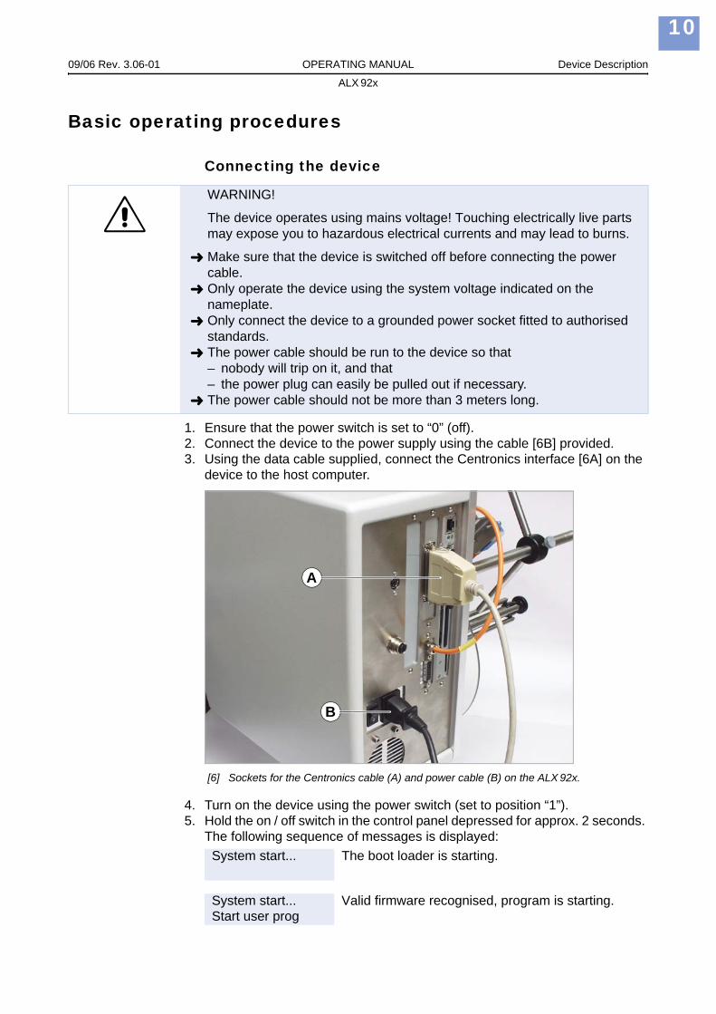
1. Ensure that the power switch is set to “0” (off). 2. Connect the device to the power supply using the cable [6B] provided. 3. Using the data cable supplied, connect the Centronics interface [6A] on the
device to the host computer.
[6] Sockets for the Centronics cable (A) and power cable (B) on the ALX 92x.
4. Turn on the device using the power switch (set to position “1”). 5. Hold the on / off switch in the control panel depressed for approx. 2 seconds.
The following sequence of messages is displayed:
WARNING!
The device operates using mains voltage! Touching electrically live parts may expose you to hazardous electrical currents and may lead to burns.
Make sure that the device is switched off before connecting the power cable.Only operate the device using the system voltage indicated on the nameplate.Only connect the device to a grounded power socket fitted to authorised standards.The power cable should be run to the device so that– nobody will trip on it, and that– the power plug can easily be pulled out if necessary.The power cable should not be more than 3 meters long.
System start... The boot loader is starting.
System start...Start user prog
Valid firmware recognised, program is starting.
A
B
09/06 Rev. 3.06-01 OPERATING MANUAL Device Description
ALX 92x
11
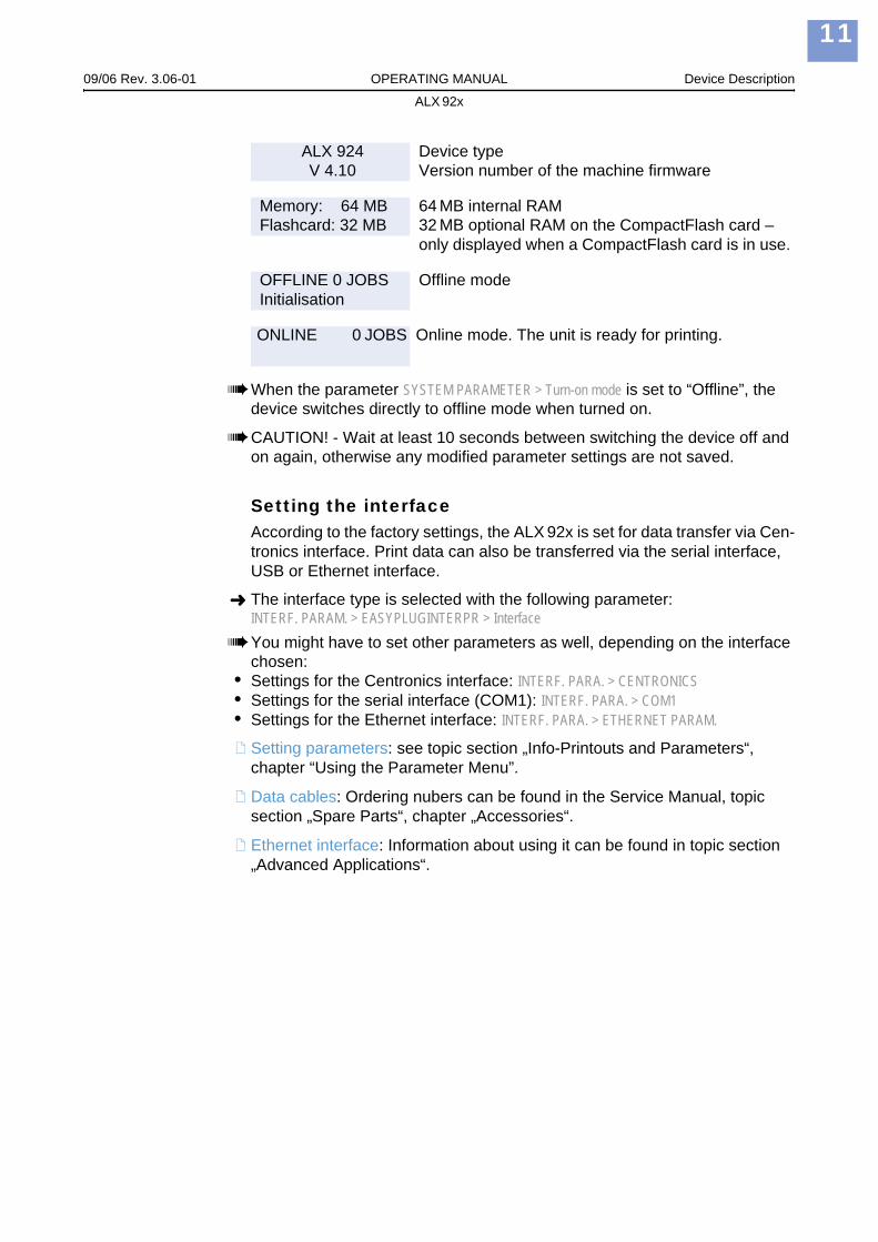
When the parameter SYSTEM PARAMETER > Turn-on mode is set to “Offline”, the device switches directly to offline mode when turned on.
CAUTION! - Wait at least 10 seconds between switching the device off and on again, otherwise any modified parameter settings are not saved.
Setting the interfaceAccording to the factory settings, the ALX 92x is set for data transfer via Cen-tronics interface. Print data can also be transferred via the serial interface, USB or Ethernet interface.
The interface type is selected with the following parameter:INTERF. PARAM. > EASYPLUGINTERPR > InterfaceYou might have to set other parameters as well, depending on the interface chosen:
• Settings for the Centronics interface: INTERF. PARA. > CENTRONICS• Settings for the serial interface (COM1): INTERF. PARA. > COM1• Settings for the Ethernet interface: INTERF. PARA. > ETHERNET PARAM.
Setting parameters: see topic section „Info-Printouts and Parameters“, chapter “Using the Parameter Menu”.
Data cables: Ordering nubers can be found in the Service Manual, topic section „Spare Parts“, chapter „Accessories“.
Ethernet interface: Information about using it can be found in topic section „Advanced Applications“.
ALX 924V 4.10
Device typeVersion number of the machine firmware
Memory: 64 MBFlashcard: 32 MB
64 MB internal RAM32 MB optional RAM on the CompactFlash card – only displayed when a CompactFlash card is in use.
OFFLINE 0 JOBSInitialisation
Offline mode
ONLINE 0 JOBS Online mode. The unit is ready for printing.
09/06 Rev. 3.06-01 OPERATING MANUAL Device Description
ALX 92x
12
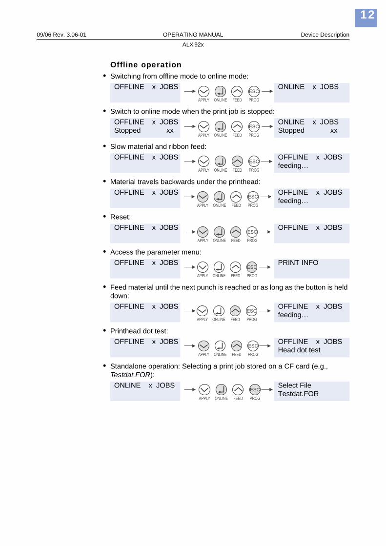
Offline operation• Switching from offline mode to online mode:
• Switch to online mode when the print job is stopped:
• Slow material and ribbon feed:
• Material travels backwards under the printhead:
• Reset:
• Access the parameter menu:
• Feed material until the next punch is reached or as long as the button is held down:
• Printhead dot test:
• Standalone operation: Selecting a print job stored on a CF card (e.g., Testdat.FOR):
OFFLINE x JOBS ONLINE x JOBS
OFFLINE x JOBSStopped xx
ONLINE x JOBSStopped xx
OFFLINE x JOBS OFFLINE x JOBSfeeding…
OFFLINE x JOBS OFFLINE x JOBSfeeding…
OFFLINE x JOBS OFFLINE x JOBS
OFFLINE x JOBS PRINT INFO
OFFLINE x JOBS OFFLINE x JOBSfeeding…
OFFLINE x JOBS OFFLINE x JOBSHead dot test
ONLINE x JOBS Select FileTestdat.FOR
ESC
APPLY ONLINE FEED PROG
ESC
APPLY ONLINE FEED PROG
ESC
APPLY ONLINE FEED PROG
ESC
APPLY ONLINE FEED PROG
ESC
APPLY ONLINE FEED PROG
ESC
APPLY ONLINE FEED PROG
ESC
APPLY ONLINE FEED PROG
ESC
APPLY ONLINE FEED PROG
ESC
APPLY ONLINE FEED PROG
09/06 Rev. 3.06-01 OPERATING MANUAL Device Description
ALX 92x
13
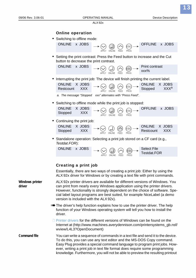
Online operation• Switching to offline mode:
• Setting the print contrast: Press the Feed button to increase and the Cut button to decrease the print contrast.
• Interrupting the print job: The device will finish printing the current label.
• Switching to offline mode while the print job is stopped:
• Continuing the print job:
• Standalone operation: Selecting a print job stored on a CF card (e.g., Testdat.FOR):
Creating a print jobEssentially, there are two ways of creating a print job: Either by using the ALX 92x driver for Windows or by creating a text file with print commands.
Windows printer driver
ALX 92x printer drivers are available for different versions of Windows. You can print from nearly every Windows application using the printer drivers. However, functionality is strongly dependent on the choice of software. Spe-cial label layout programs are best suited, for example NiceLabel (a demo version is included with the ALX 92x).
The driver’s help function explains how to use the printer driver. The help function of your Windows operating system will tell you how to install the driver.
Printer drivers for the different versions of Windows can be found on the Internet at (http://www.machines.averydennison.com/printersystems_gb.nsf/wview/L4L3?OpenDocument)
Command file You can write a sequence of commands in a text file and send it to the device. To do this, you can use any text editor and the MS-DOS Copy command. Easy Plug provides a special command language to program print jobs. How-ever, writing a print job in text file format does require some programming knowledge. Furthermore, you will not be able to preview the resulting printout
ONLINE x JOBS OFFLINE x JOBS
ONLINE x JOBS Print contrastxxx%
ONLINE X JOBSRestcount XXX
ONLINE X JOBSStopped XXXa
a. The message “Stopped xxx” alternates with “Press Feed”.
ONLINE X JOBSStopped XXX
OFFLINE x JOBS
ONLINE X JOBSStopped XXX
ONLINE X JOBSRestcount XXX
ONLINE x JOBS Select FileTestdat.FOR
ESC
APPLY ONLINE FEED PROG
ESC
APPLY ONLINE FEED PROG
ESC
APPLY ONLINE FEED PROG
ESC
APPLY ONLINE FEED PROG
ESC
APPLY ONLINE FEED PROG
ESC
APPLY ONLINE FEED PROG

09/06 Rev. 3.06-01 OPERATING MANUAL Device Description
ALX 92x
14
on the screen. Instead, you have to run a test print to see a copy of the fin-ished result.
Easy Plug Manual: here you can find a practice example of a print job together with instructions in the section “Program Example” in topic section “General, Definitions Commands Overview”.
Transferring a print jobThe device can only carry out a print job once this job has been transferred into the device’s RAM. This can be accomplished in two ways: via a direct transfer from your computer via a data cable or by saving it to a Compact-Flash (CF) card.
Data cable The print job can be transferred
– via the serial interface,– via the parallel interface, or– via the Ethernet connection.
To transfer data via the serial or parallel interface, connect the corresponding ports on the host computer and the device. Use the DOS window to send the print job file to the interface:
• Serial interface (COM1): copy testjob.txt com1
• Parallel interface (LPT1): copy testjob.txt lpt1
• USB interface / Ethernet interface: copy testjob.txt \\computername\sharename.
– Computer name = Name of the computer. You can find this name in Windows XP under START > SETTINGS > CONTROL PANEL > SYSTEM > COMPUTER NAME (e.g. DM-ECH-0990).
– For sharename, enter the name found under START > SETTINGS > PRINTERS AND FAXES after right-clicking PROPERTIES > SHARE (in Windows XP). The share name represents a device connected with a specific port – the USP port for transfer via USB, the TCP/IP port for transfer via Ethernet.
A few hints on using the USB or Ethernet interfaces:
The method described here does not work in Windows 98, Windows ME or Windows NT 4.0.The share name has to comply with the MS-DOS formatting conventions (no more than 8 characters, no symbols or spaces).
You can find further information on transferring data per Ethernet at topic section Advanced Applications
Before sending a print job from a text program, you need to ensure that the correct device driver has been installed.Special label layout programs, such as NiceLabel, make this much easier. These programs also require a driver to be installed.

09/06 Rev. 3.06-01 OPERATING MANUAL Device Description
ALX 92x
15
Plug-in card You require the following to load a print job from a CF card:• CF card (copy the print job to the directory \FORMATS)• CF card reader (to connect to your computer)
Transferring print jobs via CF card: A detailed description can be found in topic section „Advanced Applications“, chapter “Standalone Mode”.
Applying CompactFlash cardsCF = CompactFlash
The device firmware cannot utilise more than 128 MB of card storage capacity.
[7] Example: A 32 MB CF card (T1).
Suitable CF cards: see Plugin-card manual, topic section „Card types“, chapter „CompactFlash card“.
Applying CF cards: see Plugin-card manual, topic section „Application“, chapter „CompactFlash card“.
[8] Inserting the CF card (A) causes the release button (B) to come out. If the card has been inserted correctly, it will sit flush with the printer’s back wall (right)
CAUTION! - Observe the following guidelines to avoid damaging the device or the CF card.
Only use CF -cards approved by the manufacturer.Always wait at least 5 seconds after switching off the device before removing or inserting the CF card.When inserting or removing the CF card, never use force.
Wide guide notchSlim guide notch
Contacts
A
B
B
09/06 Rev. 3.06-01 OPERATING MANUAL Device Description
ALX 92x
16
Inserting a CF card 1. Switch off the device. Wait for 5 seconds.
2. Insert the CF card [8A] into the card slot, contact side first. The card’s label is on the right side.Push the CF card into the slot until the release button [8B] comes out.The differently sized guide notches [7] of the CF card prevent the card from being inserted wrongly. For the card to be inserted correctly, the wider guide notch needs to be on top.
Removing a CF card
Press the release button [8B] to remove the CF card.
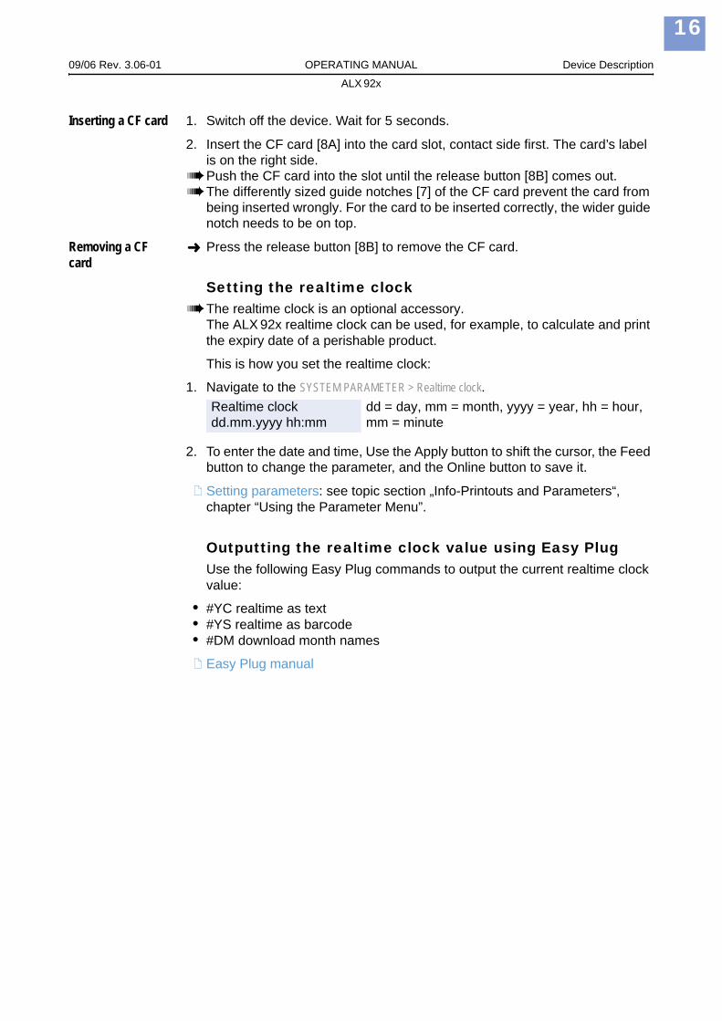
Setting the realtime clockThe realtime clock is an optional accessory.The ALX 92x realtime clock can be used, for example, to calculate and print the expiry date of a perishable product.
This is how you set the realtime clock:
1. Navigate to the SYSTEM PARAMETER > Realtime clock.
2. To enter the date and time, Use the Apply button to shift the cursor, the Feed button to change the parameter, and the Online button to save it.
Setting parameters: see topic section „Info-Printouts and Parameters“, chapter “Using the Parameter Menu”.
Outputting the realtime clock value using Easy PlugUse the following Easy Plug commands to output the current realtime clock value:
• #YC realtime as text• #YS realtime as barcode• #DM download month names
Easy Plug manual
Realtime clockdd.mm.yyyy hh:mm
dd = day, mm = month, yyyy = year, hh = hour, mm = minute
09/06 Rev. 3.06-01 OPERATING MANUAL Device Description
ALX 92x
17
The first device test
Settings for the material typeThe parameter settings described below provide the device with the neces-sary information about the label material used. When printing from a layout program, these settings are usually provided automatically by the device driv-er. For your first test prints, you need to configure them manually.
Material type • The label material is “endless”, which means that it contains no punches/perforations, breaks or reflex marks that could be recognised by the punch sensor:Set the PRINT PARAMETER > Material Type to “endless”.
• The label material contains punches, breaks or reflex marks that can be recognised by the punch sensor (referred to as “punched” material):Set the PRINT PARAMETER > Material Type to “Punched”.
Material length Set the PRINT PARAMETER > Material Length to the length of the material (in mm).
Material width Set the PRINT PARAMETER > Material Width to the width of the material (in mm).
Only for punched/perforated material:
Type of punch • Label material with breaks or punches:Set the SYSTEM PARAMETER > Light sens. type to “Punched”.
• Label material with reflex marks:Set the SYSTEM PARAMETER > Light sens. type to “Reflex”.
Setting parameters: see topic section „Info-Printouts and Parameters“, chapter “Using the Parameter Menu”.
Printing the status reportA status report printout is a perfectly adequate device test. The width of the status printout can be set to 100 mm or 50 mm. This should match the width of the label material used. The length of the printout is 200 mm.
100 mm width Navigate to PRINT INFO > Printer status.The printout that is triggered spans a label length of 2x 200 mm, listing all of the device’s current parameter settings.
50 mm width Set the SYSTEM PARAMETER > Print Info Mode to “Compact right”.Navigate to PRINT INFO > Printer Status.The printout that is triggered contains the same information as the wider print-out, compressed to a width of 50 mm.
Density If the printout is not as black as you would like it to be, increase the print den-sity as follows:

09/06 Rev. 3.06-01 OPERATING MANUAL Device Description
ALX 92x
18
1. Press the Esc button while in online mode. Display:
2. By pressing the Apply / Feed buttons, you can increase or decrease the heat energy of the printhead (in %).
The heat energy should be kept as low as possible while retaining an accept-able printing result. A high level of heat energy reduces the lifespan of the printhead.
Print contrast60%