a/v/ha ecosystem prototype using compass … · 14.2 av streaming theory proving model (tpm) ........
TRANSCRIPT
1
Project: COMPASS
Grant Agreement: 287829
Comprehensive Modelling for Advanced Systems of Systems
A/V/HA Ecosystem Prototype Using
COMPASS Methods and Tools
Date: September 2014
Document Number: D42.2
Public Document
http://www.compass-research.eu
D42.2 A/V/HA Ecosystem Prototype Using COMPASS
Methods and Tools
2
Contributors:
Klaus Kristensen (KK), Bang & Olufsen A/S
Uwe Schulze (US), Bremen
Jon Holt (JDH), ATEGO
Simon Perry (SAP), ATEGO
Richard Payne (RP), UNEW
Jeremy Bryans (JB), UNEW
Claire Ingram (CI), UNEW
Editors:
Klaus Kristensen, Bang & Olufsen A/S
Reviewers: John Fitzgerald (JF), UNEW
Kenneth Pierce (KP), UNEW
Alexandre Cabral Mota (ACM), UFPE
Document History Version Date Author Description
0.1 9.9.2014 KK Initial abstract, introduction and table of
contents for review by COMPASS
members. Incomplete.
0.2 20.9.2014 KK Updating the document according to
review from UNEW
0.2 26.9.2014 KK Updating the document according to
review from UFPE

D42.2 A/V/HA Ecosystem Prototype Using COMPASS
Methods and Tools
3
Abstract This deliverable presents a report evaluating the COMPASS technologies using a set
of B&O System of Systems (SoS) case study aspects as evaluation parameters. The
aspects represent B&O’s development process challenges regarding SoS engineering.
The development process includes SoS requirements engineering, SoS conceptual
modelling, SoS verification and SoS testing. The validation methods used in this
deliverable are COMPASS-tailored Technology Readiness Level(s) (TRLs). This
deliverable concludes with an assessment of the suitability of COMPASS’s model-
based technologies regarding B&O System of Systems challenges. The conclusions are
based on TRL evidence. The TRL evidence and the models described in this report
conclude: COMPASS model-based methodologies and tools have met B&O’s SoS/CS
engineering needs.

D42.2 A/V/HA Ecosystem Prototype Using COMPASS
Methods and Tools
4
Table of Contents
1. Introduction .......................................................................................................... 7
2. COMPASS TRL Overview ................................................................................. 8
3. Introduction to Bang & Olufsen Case Study ................................................... 11
3.1 B&O SoS Development Process Needs ...................................................................... 12
3.2 The COMPASS Approach ......................................................................................... 14
3.3 B&O COMPASS Approach Based Development Process ....................................... 15
4. B&O SoS Characteristics and Needs ............................................................... 17
5. SoS Requirement Modelling ............................................................................. 20
5.1 From Needs to Source Elements Views ..................................................................... 21
5.2 Domain Specific Semantics Rules and the Definition Rule Set Viewpoint ............. 22
5.3 SoS Requirement Stakeholders and the Context Definition Viewpoint ................. 24
5.4 Requirements and Stakeholder Impact Analysis Views .......................................... 24
5.5 Testable Requirements and the Validation Viewpoints ........................................... 26
6. SoS Architectural Modelling ............................................................................. 29
6.1 Domain Specific Architectural Framework .............................................................. 29
6.2 AV Domain Architectural Framework Needs .......................................................... 30
6.3 Domain Specific Architectural Framework Semantics ........................................... 31
6.4 Architectural Framework View Point Definitions ................................................... 33
6.5 SoS Architectural Pattern Languages ....................................................................... 34
6.6 Consistent AV Domain Architectural Modelling ..................................................... 36
6.7 Architectural Design Validation and Testing ........................................................... 37
7. Conceptual Stage Conclusion and Evaluation ................................................ 39
8. SoS Formal Modelling ....................................................................................... 44
8.1 Formal Motivations and Needs .................................................................................. 44
8.2 Design Model to Design Specification Refinement ................................................... 45
8.3 Formal Verification Models ....................................................................................... 47
8.4 Testing Formal Specification Models ........................................................................ 54
9. Formal Stage Conclusion and Evaluation ....................................................... 56
10. SoS Co-Simulation and Testing .................................................................... 60
10.1 Formal Specifications Models and SoS Target Development Environment
Refinement ......................................................................................................................... 61
10.2 Formal Specification Model Verification and SoS Environment ......................... 62

D42.2 A/V/HA Ecosystem Prototype Using COMPASS
Methods and Tools
5
10.3 SoS V&V Campaign and The Test Pattern ............................................................ 66
11. Real Stage Conclusion and Evaluation ........................................................ 66
12. Conclusion ...................................................................................................... 69
13. References ....................................................................................................... 72
14. Appendix ......................................................................................................... 75
14.1 AV Streaming Model Checker Model (MCM) ....................................................... 75
14.2 AV Streaming Theory Proving Model (TPM) ........................................................ 79
14.3 Emergent Leadership Architectural Design Specification Model (ASPM) ......... 84
14.4 Timed Transport Layer Architectural Design Specification Model (ADSM) ..... 95
14.5 OO CML Design Pattern model ............................................................................ 100
14.6 OO Clock Domain Model ....................................................................................... 104
14.7 SoS AV Device Discovery Architectural Design Specification Model (ADSM) 106
Figures:
Figure 1 - The COMPASS Approach .............................................................................. 14
Figure 2 The B&O COMPASS Approach based development process ......................... 15
Figure 3 B&O SoS level requirement description view ................................................ 19
Figure 4 The SoS level user-experience requirements for Audio-Visual Streaming .... 21
Figure 5 B&O SoS level Source Element View ............................................................. 22
Figure 6 DRSV Streaming Rule(s) ................................................................................ 23
Figure 7 subset of the Streaming RDV ......................................................................... 23
Figure 8 Streaming CDV ............................................................................................... 24
Figure 9 Source CS RCV ................................................................................................ 25
Figure 10 Streaming SoS CIV ........................................................................................ 26
Figure 11 Source CS VV ................................................................................................ 27
Figure 12 Streaming SoS VIV ........................................................................................ 28
Figure 13 B&O´s Streaming Architectural Framework´s AFCV ................................... 30
Figure 14 SAF´s Ontology Definition View ................................................................... 31
Figure 15 SAF´s Viewport Relationship View ............................................................... 32
Figure 16 Product Configuration VCV ......................................................................... 33
Figure 17 Product Configuration Viewpoint VDV ....................................................... 34
Figure 18 NMM’s ICV ................................................................................................... 35
Figure 19 NMM´s IPV ................................................................................................... 35
Figure 20 SAf´s RDV ...................................................................................................... 37
Figure 21 Test Pattern TCV instance ............................................................................ 39
Figure 22 The Conceptual stage ................................................................................... 40

D42.2 A/V/HA Ecosystem Prototype Using COMPASS
Methods and Tools
6
Figure 23 LS Contract Definition View ......................................................................... 46
Figure 24 AV SoS´s CDDV ............................................................................................. 47
Figure 25 SourceGraph CS Test Configuration View .................................................... 55
Figure 26 Formal stage ................................................................................................. 56
D42.2 A/V/HA Ecosystem Prototype Using COMPASS
Methods and Tools
7
1. Introduction
This document gives an evaluation of COMPASS, using the COMPASS Approach for
improvement of Bang & Olufsen SoS development processes. This document describes
an industrial model-based SoS/CS development process based on COMPASS
technology. The development processtarts from needs to SoS/CS product deployment.
The process contains parallel testing, validation and verification activities for the
different development stages of the process. For each stage of the MBSE development
process, a set of COMPASS technologies has been applied. The following sections will
describe how and why these COMPASS technologies are applied, and the pros and cons
of the applied technologies to the B&O COMPASS case study. The evaluation section
starts by defining B&O’s SoS problem domain and the case study aspects selected as
being representative of the SoS problem domain for this document.
For reasons of confidentiality and ease of presentation, some models and explanations
are simplified. This document will describe the use of both semi-formal and formal
COMPASS technologies in an industrial context. However, the intention is not to
provide detailed user guidelines or in-depth technology descriptions: these can be found
in other COMPASS documents, and references are provided where needed.
Note that throughout this case study document, the term refinement refers to the
refinement concepts from the COMPASS Refinement Framework [D22.4]. The term
formal refinement refers to COMPASS’s formal refinement arguments [D22.4].
This document assumes basic knowledge of SysML, CML, requirements, design and
verification engineering concepts.
To ensure comparable measuring between baseline technologies, B&O’s traditional
technologies, and COMPASS technologies, a consistent benchmarking/evaluation
method [D11.4] is used throughout the project. The benchmarking method implements
measurable classification concepts based on process and result completeness of
observable concepts regarding modelling selected structural and behavioural aspects of
a SoS. Declaring models a “success” is based on the value of the measurable attribute
sets for a given B&O SoS case study aspect. Throughout this document the measurable
attributes will be SoS development needs defined for each stage of the SoS development
model.
The concrete workflow of the benchmarking/evaluation method for this deliverable
consists of modelling aspects of the B&O A/V/HA SoS using a COMPASS technology
in which observable concepts are monitored from the process of creating the model and
in the resulting model. The level of process and result completeness of the observable
concepts is validated against B&O’s COMPASS development stage expectations and
needs.
Evaluations of COMPASS technologies consist of SoS methodologies, modelling
languages and tools evaluation. Sometimes modelling languages necessitate specific
development methods, in other situations modelling language capabilities are just
supporting elements for methods. The most common relation is that methods are
supported by modelling language capabilities and the capabilities are supported by
D42.2 A/V/HA Ecosystem Prototype Using COMPASS
Methods and Tools
8
tools. Tools represent the operational realization of methods and modelling language
capabilities.
Industry technology evaluations are heavily driven by cost optimizations. In the
technology domains, the cost optimization selling slogans are often “cut development
time” and “shorter time to market”. But technology deployment costs in the
organization are also assessed. The level of adaptability has a corresponding cost level
that will drive the choice of technology. Correct use of technology requires skills, and
developing and maintaining skills in organisations is costly. The deployment cost must
also be accounted for during evaluation and development of commercial industry target
technology. Adaptability observable concepts like technology maturity, industrial
exploitation, risk assessment and usability are cost evaluation parameters used for
COMPASS technology evaluation in this document. In this document, the COMPASS
model-based tailored TRL’s [ D11.4] are uses for both industry usability and industry
maturity measurements. Details about the COMPASS TRLs are to be found in D11.4.
To make this document more self-contained, the TRL concepts are described in Section
2 of this document.
The SoS models described in this document represent selected structural and
behavioural aspects of the B&O A/V/HA SoS suitable for evaluation of COMPASS
methods and tools. The B&O SoS business and technology domains the models are
derived from are described in Section 2. The process and results of using COMPASS
technology for the conceptual development stage are described in Sections 4, 5 and 6.
The formal stage’s process and results are described in Section 7 and 8, and finally the
results and the process of applying COMPASS technology for the Real development
stage are described in Section 9 and 10.
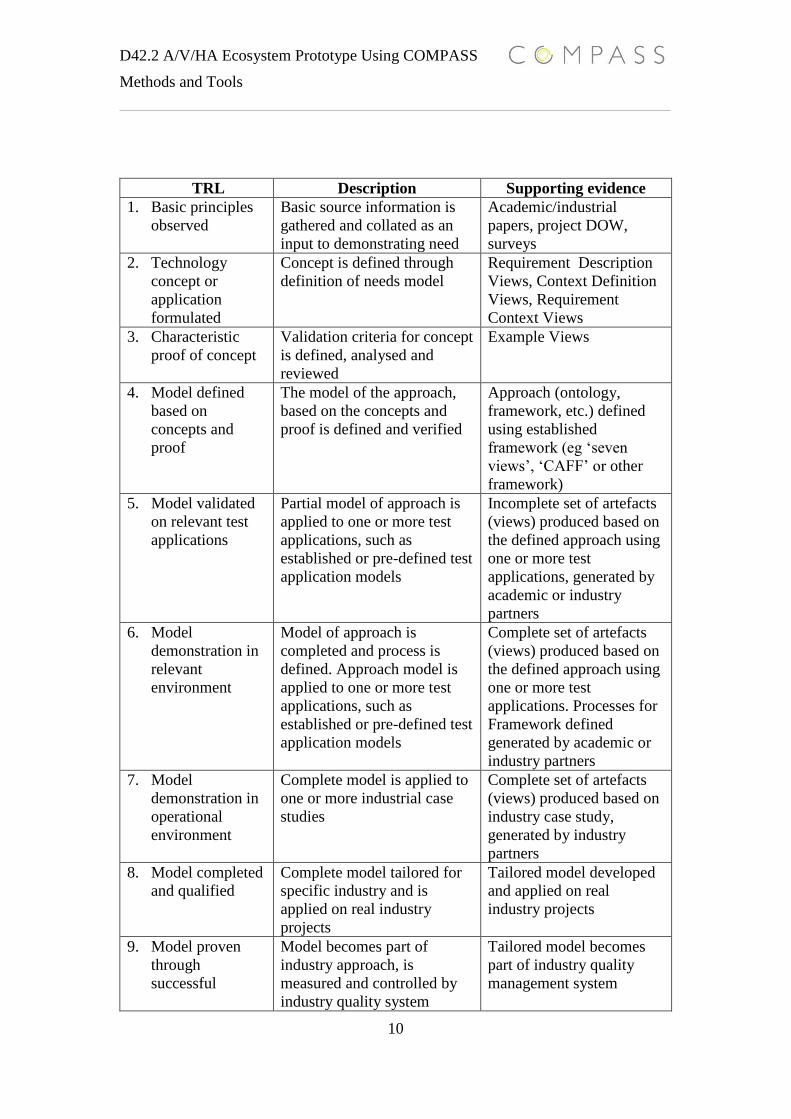
2. COMPASS TRL Overview
This section presents a tailored version of the Technology Readiness Levels (TRL) for
software as defined in
http://www.incose.org/huntsville/charts/INCOSE_Software_Technology_Readiness_
Assessment%20_11-17-05.ppt
This TRL section requires basic understanding of COMPASS Approach [D21.6]
concepts like Ontology(/ies), ViewPoint vs View Instances Process(s), and so on. The
TRLs defined here are intended to be applied to approaches (methods, methodologies,
processes, guidelines, etc.) that have been defined as part of the COMPASS project.
There are two tables defined for TRL assessment:
- Table 1 provides a high-level overview and description of each of the
technology readiness levels.
- Table 2 provides a breakdown of typical evidence types and their status (can
be found in [ D11.4]).
D42.2 A/V/HA Ecosystem Prototype Using COMPASS
Methods and Tools
9
The status of a piece of evidence may be described as follows:
- (updated) – the artefacts have been reviewed and, where necessary, updated to
reflect the results of the review
- (incomplete) – the artefacts produced do not reflect the full set of artefacts for
the approach
- (complete) - the artefacts produced reflect the full set of artefacts for the
approach
- (tailored) – the artefacts have been tailored for a specific industry
- (accepted) – the artefacts produced have been reviewed and accepted as fit for
purpose
- (adopted) – the artefacts produced have been validated and accepted as fit for
purpose and now form part of the industry QMS
Abbreviations:
- ACRE – Approach to Context-based Requirement Engineering [D21.1]
- CAFF – COMPASS Architectural Framework Framework [D21.5, D21.2]
- SEV – Source Element View (according to SoS-ACRE [D21.1])
- RDV – Requirement Description View (according to SoS-ACRE)
- CDV – Context Definition View (according to SoS-ACRE)
- RCV – Requirement Context View (according to SoS-ACRE)
- VV – Validation View (according to SoS-ACRE)
- QMS - Quality Management System [D21.6]
Definitions:
- Ontology – a definition of key concepts, their defined terminology and the
relationships between the concepts
- Framework – a definition of a set of specific Viewpoints that define the format
and content of a set of Views that address a specific purpose or meet a specific
goal. The Framework is defined according to CAFF
- Process – the definition of a set of Processes that allow the Framework to be
realised. The Processes are defined according to the ‘seven views’ [D21.1]
D42.2 A/V/HA Ecosystem Prototype Using COMPASS
Methods and Tools
10
TRL Description Supporting evidence
1. Basic principles
observed
Basic source information is
gathered and collated as an
input to demonstrating need
Academic/industrial
papers, project DOW,
surveys
2. Technology
concept or
application
formulated
Concept is defined through
definition of needs model
Requirement Description
Views, Context Definition
Views, Requirement
Context Views
3. Characteristic
proof of concept
Validation criteria for concept
is defined, analysed and
reviewed
Example Views
4. Model defined
based on
concepts and
proof
The model of the approach,
based on the concepts and
proof is defined and verified
Approach (ontology,
framework, etc.) defined
using established
framework (eg ‘seven
views’, ‘CAFF’ or other
framework)
5. Model validated
on relevant test
applications
Partial model of approach is
applied to one or more test
applications, such as
established or pre-defined test
application models
Incomplete set of artefacts
(views) produced based on
the defined approach using
one or more test
applications, generated by
academic or industry
partners
6. Model
demonstration in
relevant
environment
Model of approach is
completed and process is
defined. Approach model is
applied to one or more test
applications, such as
established or pre-defined test
application models
Complete set of artefacts
(views) produced based on
the defined approach using
one or more test
applications. Processes for
Framework defined
generated by academic or
industry partners
7. Model
demonstration in
operational
environment
Complete model is applied to
one or more industrial case
studies
Complete set of artefacts
(views) produced based on
industry case study,
generated by industry
partners
8. Model completed
and qualified
Complete model tailored for
specific industry and is
applied on real industry
projects
Tailored model developed
and applied on real
industry projects
9. Model proven
through
successful
Model becomes part of
industry approach, is
measured and controlled by
industry quality system
Tailored model becomes
part of industry quality
management system
D42.2 A/V/HA Ecosystem Prototype Using COMPASS
Methods and Tools
11
mission
operations Table 1 High-level definition of TRLs for models
Please note that throughout this document tools will be evalutated using the same
methods/process TRLs. The maturity of a tool affects the overall usability. Hence a
method/theory might be useful in industry for a given SoS problem, but the operational
tool realisation of the method might not be.
3. Introduction to Bang & Olufsen Case Study
B&O is known for design, high product quality and distinguished user experiences.
B&O is defined as a “lifestyle brand”1, and the B&O brand is routinely ranked in the
top 10 coolest brands worldwide. B&O manufactures consumer electronics products
and technology for four core business areas,
Audio and Video
o High-end AV products with proprietary connectivity and SoS
functionalities between AV and speaker products
Automotive
o Advanced car speaker systems, deployed in high-end car brands such as
Aston Martin and Audi
Speaker technology
o In addition to distinctive design, the many featuring areas which
differentiate B&O’s loudspeakers include integrated amplifiers,
ICEpower technology and Acoustic Lens Technology
Play
o A youth sub-brand, which includes products based on standard
technologies and ecosystems like Airplay,2 DLNA,3 and Android.4
A B&O SoS can contain products from all four business areas, and depending on the
product configurations, new emergent behaviours will occur and extend the users’
1 A lifestyle brand is a brand that attempts to embody the values and aspirations of a group or culture for
purposes of marketing. Each individual has an identity based on their choices, experiences, and
background (e.g. ethnicity, social class, subculture, nationality, etc.). A lifestyle brand aims to sell
products by convincing potential customers that this identity will be reinforced or supplemented if they
publicly associate themselves with the brand.
2 AirPlay (previously called AirTunes when it was for audio only) is a proprietary
protocol stack/suite developed by Apple Inc. that allows wireless streaming of audio, video, and photos,
together with related metadata between devices.
3 The Digital Living Network Alliance (DLNA) is a non-profit collaborative trade organization
established by Sony in June 2003 that is responsible for defining interoperability guidelines to enable
sharing of digital media between multimedia devices.
4 Android is a Linux-based operating system designed primarily for touchscreen mobile devices such
as smartphones and tablet computers. Initially developed by Android, Inc.

D42.2 A/V/HA Ecosystem Prototype Using COMPASS
Methods and Tools
12
experience space. This is a B&O brand characteristic and a B&O SoS requirement. The
B&O brand experience rule (BER) is defined as “1+1=2+n”, meaning if you have two
products (the 1(s)), you get the operational experience from each product (the number
2) and a set of new experiences (n defines the emergent behaviours set). In B&O
terminology, the set n is called the extended system experiences, derived from the
systems elements of the products in a given B&O SoS.
Historically, B&O has made proprietary HW and SW solutions for dealing with the
interoperability challenges consequent on the BER product requirement. Using
COMPASS SoS definitions [1], B&O SoS would just be a constituent system, because
all system elements are manageable by nature of the underlying proprietary technology.
The use of proprietary technology in B&O is causing interoperability challenges with
AV business areas evolution. The two fastest growing B&O business areas are currently
Play and Automotive, where products are based on open standard technologies and
ecosystems, and therefore conflict with the closed proprietary-based technology other
B&O products are built from. Content (media streams) is getting more and more
complex. The AV content providers enforce rules and even user-experiences that might
degenerate the B&O experiences space. Furthermore, the modern consumer is no longer
interested in buying products that only work with other products from the same
supplier. The new mantra is interoperability, and not only on a SCART or HDMI
connector level, but also transparent network interoperability. The business areas and
technology challenges mentioned above are forcing B&O to move away from the old
closed technology base towards a more open philosophy.
The move from closed to open interoperable technology challenges management of
emergent behaviours for B&O. The set of emergent behaviours must conform to B&O
brand experience rules regarding robustness and quality attributes. The robustness and
experience space is now heavily influenced by the constituent systems and the contracts
among the constituent systems. In addition, unmanaged emergent behaviours might
even degrade the B&O SoS and lead to brand damages.
The open philosophy is causing a paradigm shift from system to SoS engineering in the
B&O development organization. B&O is going from developing constituent systems to
SoS level engineering. The organization evolution requirements are also driven by
hostile business and technology domains represented by constituent systems of the SoS.
The organization must be in a state where reasoning and validation regarding impact of
uncontrollable constituent systems can be communicated among different disciplinary
domains in the organization.
3.1 B&O SoS Development Process Needs
B&O’s SoS business and technology challenges define a set of COMPASS
expectations, whose development process needs are elicited from and used in
COMPASS technology evaluation.
The B&O COMPASS expectations are:
that the COMPASS results will allow them to formally manage SoS
requirements for emergent behaviours

D42.2 A/V/HA Ecosystem Prototype Using COMPASS
Methods and Tools
13
that the COMPASS work will have a positive impact on the B&O’s SoS
software development process by improving software quality and SoS
robustness
in the long-term, that the methods and tools made available by COMPASS will
bring together the various project groups that today work quite independently,
streamlining software development, and allowing them to work on a single
SoS
The B&O COMPASS expectations translate into the following high-level development
process needs:
SoS Requirement Stage Requirements
o RS_REQ_1: Identification and definition of SoS/CS requirement
stakeholders
o RS_REQ_2: SoS/CS stakeholder requirement impact analysis
o RS_REQ_3: SoS/CS requirement traceability from/to stakeholders and
sources
o RS_REQ_4: SoS/CS requirements that conform to standard requirement
quality attributes as understandable, consistent, testable and traceable.
o RS_REQ_5: Consistent SoS/CS requirement communication among
different stakeholders
SoS Architectural Design Stage Requirements
o DS_REQ_1: Consistent SoS/CS architectural level communication,
development, and decision making among different development
disciplines
o DS_REQ_2: Capability of expressing and analyzing SoS/CS models
during early design stages
o DS_REQ_3: Capability of identified areas of incompleteness or
ambiguity in informal system specifications during early design stages
o DS_REQ_4: Capability of validation and testing of conceptual SoS/CS
design models
SoS Testing Stage Requirements
o TS_REQ_1: Capabilities of identified needed SoS/CS test cases for
different AV product configurations
o TS_REG_2: Capabilities of testing SoS/CS properties in different AV
product configurations
D42.2 A/V/HA Ecosystem Prototype Using COMPASS
Methods and Tools
14
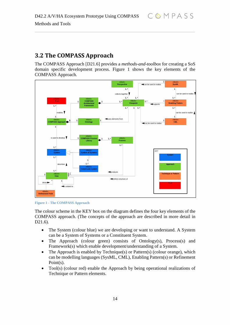
3.2 The COMPASS Approach
The COMPASS Approach [D21.6] provides a methods-and-toolbox for creating a SoS
domain specific development process. Figure 1 shows the key elements of the
COMPASS Approach.
Figure 1 - The COMPASS Approach
The colour scheme in the KEY box on the diagram defines the four key elements of the
COMPASS approach. (The concepts of the approach are described in more detail in
D21.6).
The System (colour blue) we are developing or want to understand. A System
can be a System of Systems or a Constituent System.
The Approach (colour green) consists of Ontology(s), Process(s) and
Framework(s) which enable development/understanding of a System.
The Approach is enabled by Technique(s) or Pattern(s) (colour orange), which
can be modelling languages (SysML, CML), Enabling Pattern(s) or Refinement
Point(s).
Tool(s) (colour red) enable the Approach by being operational realizations of
Technique or Pattern elements.
1..*
1
1..*
1
1..*
1..*
*
1
1
1
1
1..*
1..*
1..*
1..*1
1..*1
1..* *
1..*
1
1..*
1
1..*
1
1..*
1
1
1..*
1
1
1
1
1..*
1
11
1..*
1..*
KEY
«block»
COMPASS Approach
«block»
System
«block»
Constituent System
«block»
System of Systems
«block»
Refinement Point
«block»
CML
«block»
Perspective
«block»
Ontology
«block»
COMPASS
Architectural
Framework
«block»
COMPASS Process
Library
«block»
Enabling Pattern
«block»
SysML
«block»
Tool
System
Approach
Technique or Pattern
Tool
«block»
Viewpoint
«block»
Process
«block»
View
1..*
1
1..*
1
is used to develop
1..*
1..*
describes
*
1
drives1
1
is related to
1
1..*
uses elements from
1..*
1..*
collects together
1..*1
1..*1
1..* *
supports
1..*
1
can be used to realise
1..*
1
can be used to realise
1..*
1
can be used to realise
1..*
1
can be used to realise
1
1..*
enables
1
1
1
1
1..*
1
defines structure of
11
1..*
1..*
produces
15
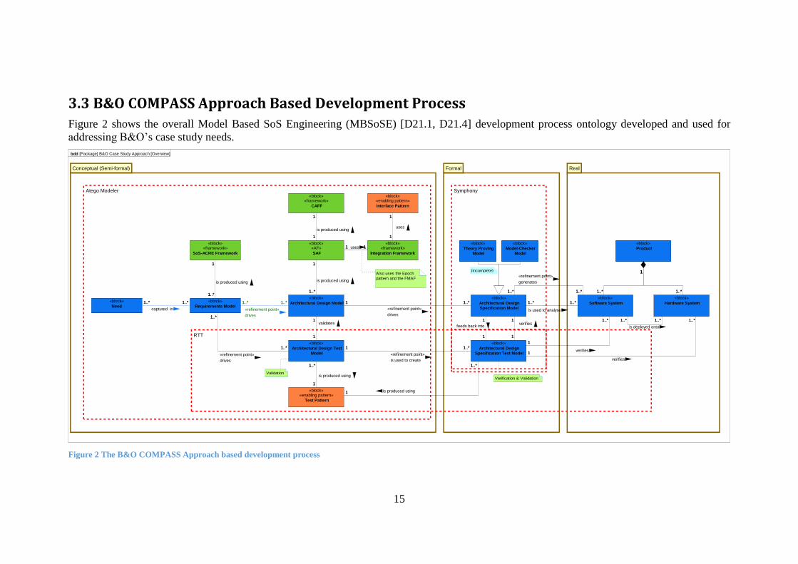
3.3 B&O COMPASS Approach Based Development Process
Figure 2 shows the overall Model Based SoS Engineering (MBSoSE) [D21.1, D21.4] development process ontology developed and used for
addressing B&O’s case study needs.
Figure 2 The B&O COMPASS Approach based development process
1..*1..* 1..*1..*
1
1
1..*
1..*
1
1..*
1
1..*
1
1..*
1
1
1
1
11
1..*1
1..*1
1
1..*
1
11
1
1..*
1
1..*
1
1..*1..*
1..*1..*
1..*1..*1..*
1
1..*
1
bdd [Package] B&O Case Study Approach [Overview]
Atego Modeler Symphony
RTT
Conceptual (Semi-formal)
«block»«framework»
CAFF
«block»«enabling pattern»
Interface Pattern
«block»«framework»
Integration Framework
«block»«AF»
SAF
«block»«framework»
SoS-ACRE Framework
«block»«enabling pattern»
Test Pattern
«block»
Architectural Design Test
Model
«block»
Architectural Design Model«block»
Requirements Model
«block»
Need
«block»«framework»
CAFF
«block»«enabling pattern»
Interface Pattern
«block»«framework»
Integration Framework
«block»«AF»
SAF
«block»«framework»
SoS-ACRE Framework
«block»«enabling pattern»
Test Pattern
«block»
Architectural Design Test
Model
«block»
Architectural Design Model«block»
Requirements Model
«block»
Need
Formal
«block»
Theory Proving
Model
«block»
Model-Checker
Model
«block»
Architectural Design
Specification Model
«block»
Architectural Design
Specification Test Model
«block»
Theory Proving
Model
«block»
Model-Checker
Model
«block»
Architectural Design
Specification Model
«block»
Architectural Design
Specification Test Model
Real
«block»
Product
«block»
Software System
«block»
Hardware System
«block»
Product
«block»
Software System
«block»
Hardware System1..*1..*
captured in
1..*1..*
«refinement point»
drives1
1
validates
1..*
1..*
«refinement point»
drives
1
1..*
is produced using
1
1..*
is produced using
1
1..*
is produced using
1
1
is produced using
1
1
uses
11 uses
1..*1
«refinement point»
drives
1..*1
«refinement point»
is used to create
1
1..*
is produced using
1
1
verifies
1
1
feeds back into
1..*
1
1..*
1
1..*1..*
«refinement point»
generates
1..*1..*
is used to analyse
1..*1..*
is deployed onto
1..*
1
verifies
1..*
1
verifies
{incomplete}
Validation
Also uses the Epoch
pattern and the FMAF
Verification & Validation
16
The MBSoSE process is the result of applying the COMPASS Approach to the B&O
case study SoS development process needs. The development process consists of three
main development stages with the following COMPASS Approach System concepts
(the blue elements in Figure 1) and ontology relationships.
The Conceptual stage contains the identification/understanding of Need(s). The
Needs(s) are captured in the Requirement Model. The Requirement Model
drives the Architectural Design Model. The Architectural Design Test
Model(s), which are refinements of the Requirement Model, validates the
Architectural Design Model.
The Formal stage contains one or more Architectural Design Specification
Model(s), which are driven by the Architectural Design Model. Architectural
Design Specification Model(s) can be a Model Checker Model or a Theory
Proving Model. The Architectural Design Specification Test Model(s) verifies
the Architectural Design Specification Model(s). There is a recursion
relationship between the Architectural Design Specification Model and the
Architectural Design Specification Test Model(s). The Architectural Design
Specification Test Model can be created from the Architectural Design Test
Model, and used for validating the Architectural Design Specification Model or
from elements (traces, proofs, contracts) of a proven Architectural Design
Specification Model. The Architectural Design Specification Test Model(s)
often start off as a semi-formal refinement of the Architectural Design Test
Model and then transition to an Architectural Design Specification Model.
The Real stage contains the B&O Product(s), which is a specialization of the
COMPASS ontology concept System. A Product consists of Software
System(s) and Hardware System(s). A Product can be generated from an
Architectural Design Specification Model or be analysed by an Architectural
Design Specification Model. A Product has been verified by the Architectural
Design Specification Test Model. Software Systems(s) are deployed onto
Hardware System(s).
Please note the MBSoSE development model does not have a specific testing stage.
The testing activities are embedded into each stage. Testing does not only happen at the
end of development, but runs parallel throughout the development process. Hence
different development stages have different testing needs and scopes.
The following sections will describe the motivation for the different development
stages and the results (the blue coloured COMPASS Approach ontology concepts) of
applying COMPASS technologies for a given stage. This means describing the red,
orange and green coloured ontology concepts on the diagram in Figure 2. The
descriptions of the MBSoSE process will start by defining the AV SoS characteristics
using the COMPASS SoS definitions in D11.1 and D11.3. Scoping the SoS domain is
the first step in understanding and communicating the fundamental case study’s
Need(s) and B&O’s AV SoS problem domain.
D42.2 A/V/HA Ecosystem Prototype Using COMPASS
Methods and Tools
17
4. B&O SoS Characteristics and Needs
This section will describe how to scope the Need(s) part of the Conceptual stage in the
MBSoSE process using COMPASS technology. Before capturing Need(s) in the
Requirement Model we must enable communication and understanding of the
constraints and possibilities caused by technology and business stakeholders in the SoS
environment.
In the B&O case study development process, the COMPASS Concept Base [D11.2,
D11.3] is used as a base ontology element for the SoS domain. The COMPASS Concept
base combined with the guideline processes given in Initial Report on Guidelines for
Architectural Level SoS Modelling [D21.2] enabled consistent communication
regarding various SoS aspects in the B&O SoS environment by giving abstract
conceptual descriptions of SoS elements like SoS classifications, dominant SoS
architectures, SoS properties and the domain specific concepts (ontologies). The
COMPASS deliverables enabled the possibility of reasoning and decision making
regarding needed capabilities and limitations among technical and non-technical
stakeholders in B&O’s development organisation. The following AV domain SoS
knowledge has been captured using the COMPASS guidelines.
B&O SoS classification
The SoS can be considered a virtual SoS, since there is no central management
authority or agreed-upon purpose. However, at times, the system enters a state where
a designated manager is selected and constituent systems recognise some global
objectives, which we regard as collaborative. In the case study aspect AV Streaming
the CSs agree to take roles as source, renderer or content provider to realise the SoS
objective streaming AV contents. In the leadership case study aspect, the protocol
defines the roles and role rules needed for enabling the desired property of a leader in
the SoS.
B&O SoS dominant Architecture
Service-oriented architecture (at the application layer). Constituent systems may offer
services, consume services or act as a broker for discovering services available within
the system and the policies that are attached to them. Other layers may exhibit other
architectures – for example, the streaming layer from the AV streaming case study is
characterised as a pipe-and-filter architecture, where the control layer of the Leadership
case study is Service-oriented architecture.
B&O SoS properties
Here we consider the B&O case study in relation to the eight COMPASS properties of
SoS.
High autonomy
o Some constituents are supplied by third party manufacturers or are
stand-alone products produced by individual teams at Bang & Olufsen.
High independence
D42.2 A/V/HA Ecosystem Prototype Using COMPASS
Methods and Tools
18
o The components each have a purpose (e.g., a television set, a speaker)
which means they can continue to have a meaningful existence if the
SoS is removed.
High Distribution
o Constituents are distributed within (a) room(s).
Swift Evolution
o The SoS evolves substantially over a short number of years as new
technologies make it possible to stream new types of data to new types
of devices.
Considerable emergence
o The emergent behaviour is the ability to stream and manage content
between distributed devices associated with a user account. Users can
uncover new emergent behaviour by finding new combinations of
content server and playback device. Unexpected emergent behaviour
must still conform to brand expectations.
High dynamicity
o New unexpected devices and/or content may be added to the system or
removed from it at any time, requiring the system to incorporate a new
constituent into the architecture or cope with the loss of a former
constituent.
Strong interdependence
o All constituents recognise the need to make sacrifices where necessary
to abide by DRM regulations. Some constituents have a dependency on
others – for example, devices for rendering content have a dependency
on devices that store, stream and manage content and the relevant
policies.
Some interoperability
o A third party protocol for data exchange is employed and understood by
many devices. There are many different standards, however, and not all
products are capable of interoperating freely.
Based on the SoS characteristics of the AV SoS and B&O’s business needs we can
summarize the SoS business challenges as an SoS technology integration challenge
which, simplified, stipulates “seamless integration of non-B&O system(s) while
preserving B&O brand DNA”. The term B&O DNA means B&O’s unique selling
points, like extended user-experiences and high product quality in an SoS context, even
when non-B&O products are part of an AV SoS configuration.
D42.2 A/V/HA Ecosystem Prototype Using COMPASS
Methods and Tools
19
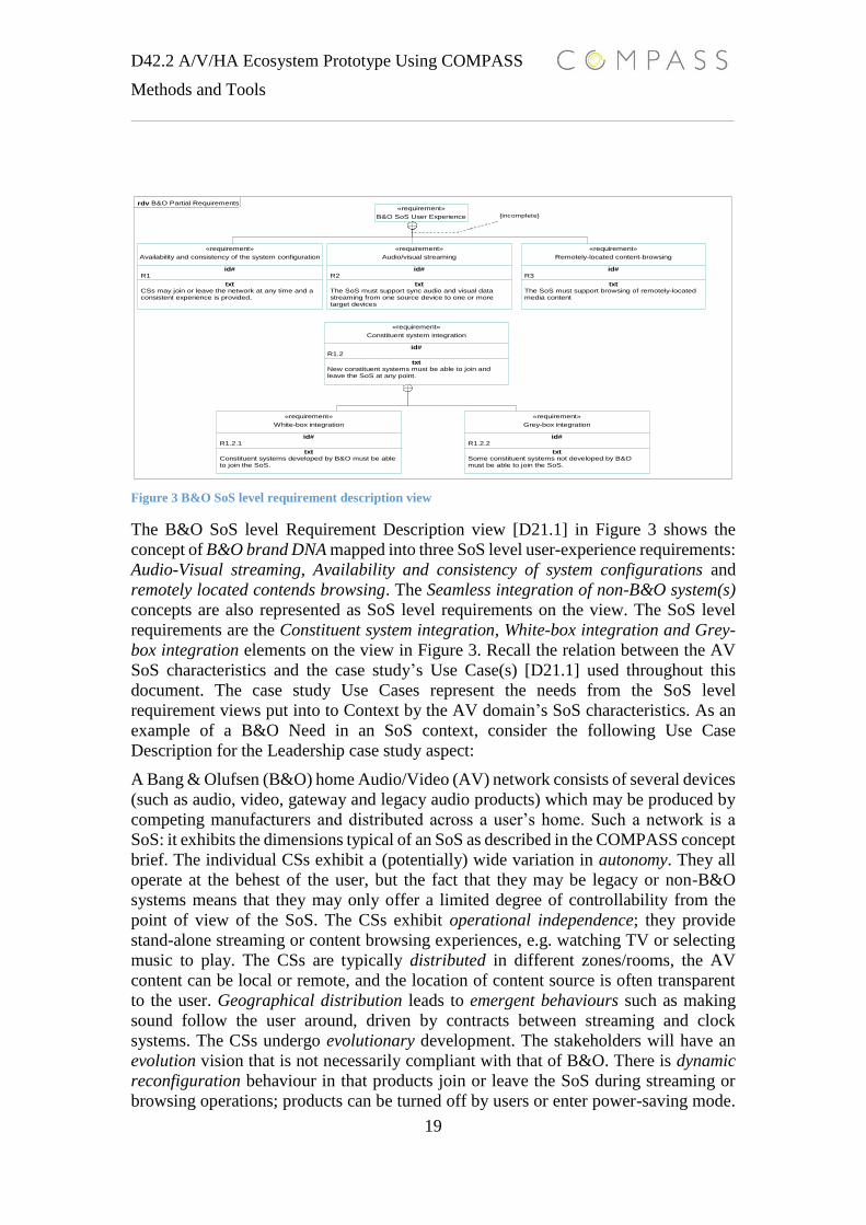
Figure 3 B&O SoS level requirement description view
The B&O SoS level Requirement Description view [D21.1] in Figure 3 shows the
concept of B&O brand DNA mapped into three SoS level user-experience requirements:
Audio-Visual streaming, Availability and consistency of system configurations and
remotely located contends browsing. The Seamless integration of non-B&O system(s)
concepts are also represented as SoS level requirements on the view. The SoS level
requirements are the Constituent system integration, White-box integration and Grey-
box integration elements on the view in Figure 3. Recall the relation between the AV
SoS characteristics and the case study’s Use Case(s) [D21.1] used throughout this
document. The case study Use Cases represent the needs from the SoS level
requirement views put into to Context by the AV domain’s SoS characteristics. As an
example of a B&O Need in an SoS context, consider the following Use Case
Description for the Leadership case study aspect:
A Bang & Olufsen (B&O) home Audio/Video (AV) network consists of several devices
(such as audio, video, gateway and legacy audio products) which may be produced by
competing manufacturers and distributed across a user’s home. Such a network is a
SoS: it exhibits the dimensions typical of an SoS as described in the COMPASS concept
brief. The individual CSs exhibit a (potentially) wide variation in autonomy. They all
operate at the behest of the user, but the fact that they may be legacy or non-B&O
systems means that they may only offer a limited degree of controllability from the
point of view of the SoS. The CSs exhibit operational independence; they provide
stand-alone streaming or content browsing experiences, e.g. watching TV or selecting
music to play. The CSs are typically distributed in different zones/rooms, the AV
content can be local or remote, and the location of content source is often transparent
to the user. Geographical distribution leads to emergent behaviours such as making
sound follow the user around, driven by contracts between streaming and clock
systems. The CSs undergo evolutionary development. The stakeholders will have an
evolution vision that is not necessarily compliant with that of B&O. There is dynamic
reconfiguration behaviour in that products join or leave the SoS during streaming or
browsing operations; products can be turned off by users or enter power-saving mode.
rdv B&O Partial Requirements«requirement»
B&O SoS User Experience
«requirement»
id#R1
txtCSs may join or leave the network at any time and aconsistent experience is provided.
Availability and consistency of the system configuration
«requirement»
id#R2
txtThe SoS must support sync audio and visual datastreaming from one source device to one or moretarget devices
Audio/visual streaming
«requirement»
id#R3
txtThe SoS must support browsing of remotely-locatedmedia content
Remotely-located content-browsing
«requirement»
id#R1.2
txtNew constituent systems must be able to join andleave the SoS at any point.
Constituent system integration
«requirement»
id#R1.2.1
txtConstituent systems developed by B&O must be ableto join the SoS.
White-box integration
«requirement»
id#R1.2.2
txtSome constituent systems not developed by B&Omust be able to join the SoS.
Grey-box integration
{incomplete}
D42.2 A/V/HA Ecosystem Prototype Using COMPASS
Methods and Tools
20
While products have no interdependence, CSs rely on each other in order to deliver the
emergent behaviour that fulfils the SoS goal.
Constituent systems may join or leave the network at any time, but a consistent user
experience (such as a playlist, current song, etc.) must be provided, and this requires
availability and consistency of the system configuration data. In order to do this, a
publish/subscribe architecture is employed. This in turn requires that the underlying
network is able to elect a leader from among the CSs. As there is no centralized control,
the ability to elect a leader is a required emergent property of the SoS.
The leadership problem is a distributed consensus problem in a network with unreliable
processes and asynchronous communication. When the CSs of the network are in an
election state, no publisher is present and the multi-room experience space is
inconsistent and unavailable. During the election, the devices must react to a set of local
transition rules that will guarantee the desired emergent property of a leader in the
network, and allow the network to enter the publisher-subscriber state.
The abstract conceptual descriptions of SoS elements produced in the Need step are
further used in the development process. The Need products act as base input for
realization of Viewpoint(s) such as Source Elements and Context Definition views from
the SoS-ARCE framework. The Need step products also act as the foundations for
development of SoS domain-specific ontology views. The next section will describe
how the products of the Need step are used as input to the SoS-ARCE framework.
5. SoS Requirement Modelling
The Conceptual stage contains The Requirement Model. The Needs(s) are captured in
the Requirement Model. The Requirement Model must therefore be a vertical
refinement of Need elements, and the Requirement Model must satisfy the following
B&O development process needs regarding SoS requirement engineering:
o RS_REQ_1: Identification and definition of SoS/CS requirement
stakeholders
o RS_REQ_2: SoS/CS stakeholder requirement impact analysis
o RS_REQ_3: SoS/CS requirement traceability from/to stakeholders and
sources
o RS_REQ_4: SoS/CS requirements that conform to standard requirement
quality attributes as understandable, consistent, testable and traceable.
o RS_REQ_5: Consistent SoS/CS requirement communication among
different stakeholders
B&O uses the SoS-ARCE framework [D21.1] for realization of the requirement models
in the MBSoSE development process. The viewpoints from SoS-ARCE provide the
processes for creating the concrete requirement views. The set of instantiated views
individually or combined meets one or more of B&O’s development process
requirements. As a proof of concept, the rest of this section will describe the results of
D42.2 A/V/HA Ecosystem Prototype Using COMPASS
Methods and Tools
21
applying SoS-ARCE to the SoS level user-experience requirement Audio-Visual
Streaming from the SoS Level Requirement Description view in Figure 3.
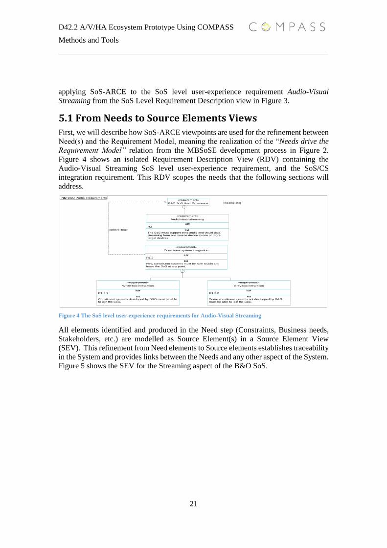
5.1 From Needs to Source Elements Views
First, we will describe how SoS-ARCE viewpoints are used for the refinement between
Need(s) and the Requirement Model, meaning the realization of the “Needs drive the
Requirement Model” relation from the MBSoSE development process in Figure 2.
Figure 4 shows an isolated Requirement Description View (RDV) containing the
Audio-Visual Streaming SoS level user-experience requirement, and the SoS/CS
integration requirement. This RDV scopes the needs that the following sections will
address.
Figure 4 The SoS level user-experience requirements for Audio-Visual Streaming
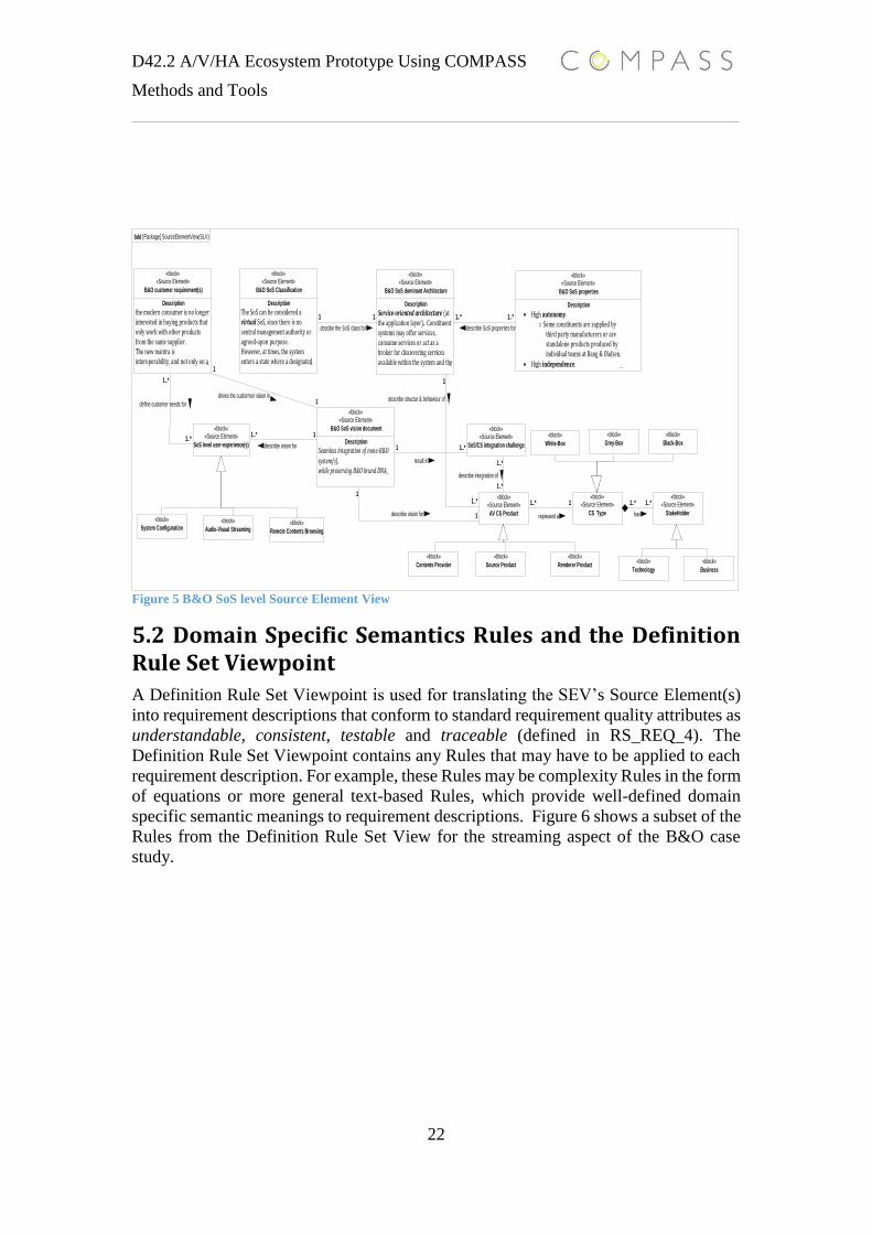
All elements identified and produced in the Need step (Constraints, Business needs,
Stakeholders, etc.) are modelled as Source Element(s) in a Source Element View
(SEV). This refinement from Need elements to Source elements establishes traceability
in the System and provides links between the Needs and any other aspect of the System.
Figure 5 shows the SEV for the Streaming aspect of the B&O SoS.
rdv B&O Partial Requirements«requirement»
B&O SoS User Experience
«requirement»
id#R2
txtThe SoS must support sync audio and visual datastreaming from one source device to one or moretarget devices
Audio/visual streaming
«requirement»
id#R1.2
txtNew constituent systems must be able to join andleave the SoS at any point.
Constituent system integration
«requirement»
id#R1.2.1
txtConstituent systems developed by B&O must be ableto join the SoS.
White-box integration
«requirement»
id#R1.2.2
txtSome constituent systems not developed by B&Omust be able to join the SoS.
Grey-box integration
{incomplete}
«deriveReqt»
D42.2 A/V/HA Ecosystem Prototype Using COMPASS
Methods and Tools
22
Figure 5 B&O SoS level Source Element View
5.2 Domain Specific Semantics Rules and the Definition Rule Set Viewpoint
A Definition Rule Set Viewpoint is used for translating the SEV’s Source Element(s)
into requirement descriptions that conform to standard requirement quality attributes as
understandable, consistent, testable and traceable (defined in RS_REQ_4). The
Definition Rule Set Viewpoint contains any Rules that may have to be applied to each
requirement description. For example, these Rules may be complexity Rules in the form
of equations or more general text-based Rules, which provide well-defined domain
specific semantic meanings to requirement descriptions. Figure 6 shows a subset of the
Rules from the Definition Rule Set View for the streaming aspect of the B&O case
study.
1..* 11..*
1..*
1..* 1..*11
1..*
1..*
1
1
1..*1
11..* 1..*1..*
1
11..*
1
bdd [Package] SourceElementView(SLV)
«block»«Source Element»
Description
the modern consumer is no longer interested in buying products that only work with other products from the same supplier.The new mantra is interoperability, and not only on a ...
B&O customer requirement(s)
«block»«Source Element»
Description
The SoS can be considered a virtual SoS, since there is no central management authority or agreed-upon purpose. However, at times, the system enters a state where a designated ...
B&O SoS Classification
«block»«Source Element»
Description
Service-oriented architecture (at the application layer). Constituent systems may offer services, consume services or act as a broker for discovering services available within the system and the ...
B&O SoS dominant Architecture
«block»«Source Element»
Description
High autonomy. o Some constituents are supplied by
third party manufacturers or are standalone products produced by individual teams at Bang & Olufsen.
High independence. ...
B&O SoS properties
«block»«Source Element»
Description
Seamless integration of none-B&O
system(s), while preserving B&O brand DNA...
B&O SoS vision document«block»«Source Element»
SoS level user-experience(s)
«block»
System Configuration«block»
Audio-Visual Streaming«block»
Remote Contents Browsing
«block»«Source Element»
SoS/CS integration challenge
«block»
Contents Provider
«block»«Source Element»
AV CS Product
«block»
Source Product
«block»
Renderer Product
«block»«Source Element»
CS Type
«block»
White-Box
«block»
Grey-Box
«block»
Black-Box
«block»«Source Element»
StakeHolder
«block»
Technology
«block»
Business
1..* 1
describe vision for1..*
1..*
define customer needs for
1..* 1..*
describe SoS properties for
11
descibe the SoS class for
1..*
1..*
describe integration of
1
1
drives the custormer vision in
1..*1
result in
11..*
represent a
1..*1..*
has1
1
describe vision for
1..*
1
describe structur & behaviour of
D42.2 A/V/HA Ecosystem Prototype Using COMPASS
Methods and Tools
23
Figure 6 DRSV Streaming Rule(s)
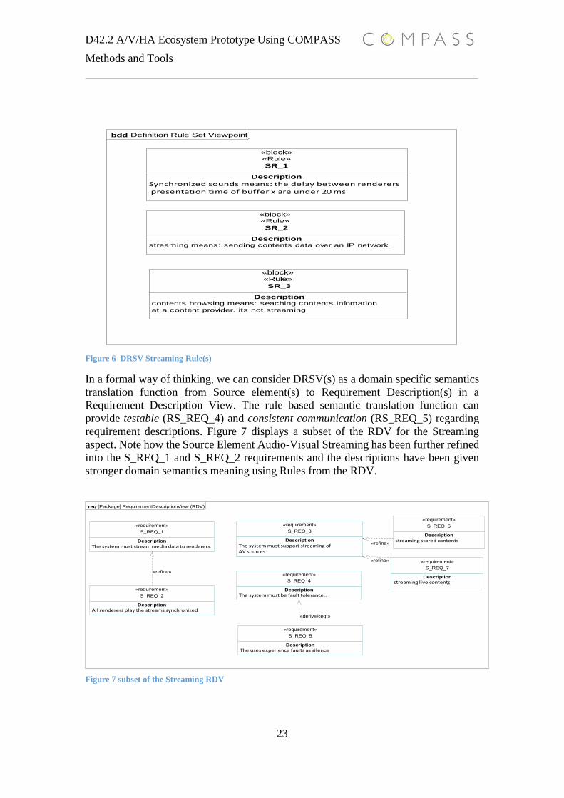
In a formal way of thinking, we can consider DRSV(s) as a domain specific semantics
translation function from Source element(s) to Requirement Description(s) in a
Requirement Description View. The rule based semantic translation function can
provide testable (RS_REQ_4) and consistent communication (RS_REQ_5) regarding
requirement descriptions. Figure 7 displays a subset of the RDV for the Streaming
aspect. Note how the Source Element Audio-Visual Streaming has been further refined
into the S_REQ_1 and S_REQ_2 requirements and the descriptions have been given
stronger domain semantics meaning using Rules from the RDV.
Figure 7 subset of the Streaming RDV
bdd Definition Rule Set Viewpoint
«block»«Rule»
Description
Synchronized sounds means: the delay between renderers presentation time of buffer x are under 20 ms
SR_1
«block»«Rule»
Descriptionstreaming means: sending contents data over an IP network ...
SR_2
«block»«Rule»
Descriptioncontents browsing means: seaching contents infomation
at a content provider. its not streaming
SR_3
req [Package] RequirementDescriptionView (RDV)
«requirement»
Description
The system must stream media data to renderers.
S_REQ_1
«requirement»
Description
All renderers play the streams synchronized
S_REQ_2
«requirement»
Description
The system must support streaming of AV sources
S_REQ_3
«requirement»
Description
The system must be fault tolerance..
S_REQ_4
«requirement»
Description
The uses experience faults as silence
S_REQ_5
«requirement»
Description
streaming stored contents
S_REQ_6
«requirement»
Description
streaming live contents...
S_REQ_7
«deriveReqt»
«refine»
«refine»
«refine»
D42.2 A/V/HA Ecosystem Prototype Using COMPASS
Methods and Tools
24
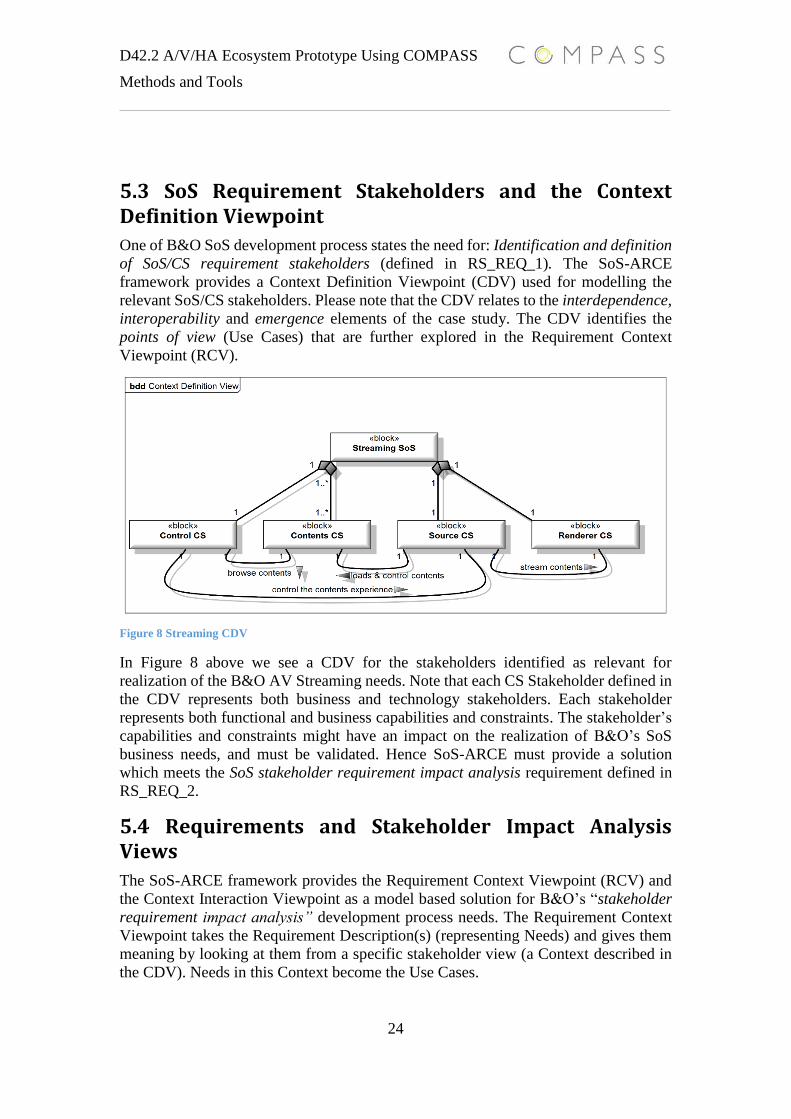
5.3 SoS Requirement Stakeholders and the Context Definition Viewpoint
One of B&O SoS development process states the need for: Identification and definition
of SoS/CS requirement stakeholders (defined in RS_REQ_1). The SoS-ARCE
framework provides a Context Definition Viewpoint (CDV) used for modelling the
relevant SoS/CS stakeholders. Please note that the CDV relates to the interdependence,
interoperability and emergence elements of the case study. The CDV identifies the
points of view (Use Cases) that are further explored in the Requirement Context
Viewpoint (RCV).
Figure 8 Streaming CDV
In Figure 8 above we see a CDV for the stakeholders identified as relevant for
realization of the B&O AV Streaming needs. Note that each CS Stakeholder defined in
the CDV represents both business and technology stakeholders. Each stakeholder
represents both functional and business capabilities and constraints. The stakeholder’s
capabilities and constraints might have an impact on the realization of B&O’s SoS
business needs, and must be validated. Hence SoS-ARCE must provide a solution
which meets the SoS stakeholder requirement impact analysis requirement defined in
RS_REQ_2.
5.4 Requirements and Stakeholder Impact Analysis Views
The SoS-ARCE framework provides the Requirement Context Viewpoint (RCV) and
the Context Interaction Viewpoint as a model based solution for B&O’s “stakeholder
requirement impact analysis” development process needs. The Requirement Context
Viewpoint takes the Requirement Description(s) (representing Needs) and gives them
meaning by looking at them from a specific stakeholder view (a Context described in
the CDV). Needs in this Context become the Use Cases.

D42.2 A/V/HA Ecosystem Prototype Using COMPASS
Methods and Tools
25
Formally speaking, a Use Case is a domain specific refinement of a given Requirement
Description, where (𝑢𝑠𝑠𝑎𝑡⊏
𝑟𝑑, 𝑢𝑠 ∈ 𝑈𝑆𝐸𝐶𝐴𝑆𝐸, 𝑟𝑑 ∈ 𝑅𝐷) might be true, if us is a
valid refinement of rd. The stakeholder will redefine the Requirement Description(s)
with the stakeholder’s domain specific capabilities and constraints. The Use Case(s)
can thereby communicate the stakeholder’s impact on the requirements and enabled
production of consistent requirements across stakeholder domains.
Correct use of RCVs and the RCV processes can satisfy B&O’s SoS development
process needs defined in RS_REQ_2 and RS_REQ_4. Figure 9 shows a RCV for the
SoS technology stakeholder Source CS.
Figure 9 Source CS RCV
The process driving the production of the CDVs is a map-reduce/ divide and conquer
approach with following process:
1. For all r:REQ do
2. Identify the main stakeholder x of r
3. Let x redefine r to r`: Use Case, with x’s domain specific capabilities
4. Identify the set of secondary stakeholder Y of r`, for all y of Y, start step 3 with
x = y and r = r`
5. Perform req impact analysis and consistent check between all Use Case variants
of r
The problem with this process is that the level of stakeholder requirement refinement
coverage depends on our understanding of the relationships between the stakeholders
(Step 2 & 4). Concrete view instances of SoS-ARCE’s Context Interaction Viewpoint
(CIV) provide an overview of the relationships between the stakeholders (Contexts)
that make up the SoS. The CIV combined with the CDVs can provide the needed
information to ensure full stakeholder requirement refinement coverage. Full
stakeholder requirement refinement coverage ensures all requirements are consistent
and all stakeholder’s impact on requirements are known. This is extremely useful
information for B&O because of the SoS level need for integration of non-B&O
products. These CS stakeholders often have a negative impact on what B&O can offer
Renderer CS
ContentsProvider
Control CS
The system muststream media data
to renderers.
The system mustsupport streaming
of AV contents
The system mustbe fault tolerance
«include»
«include»
«include»
Source CS
D42.2 A/V/HA Ecosystem Prototype Using COMPASS
Methods and Tools
26
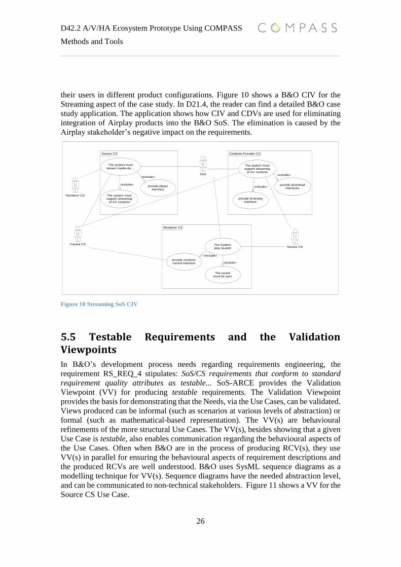
their users in different product configurations. Figure 10 shows a B&O CIV for the
Streaming aspect of the case study. In D21.4, the reader can find a detailed B&O case
study application. The application shows how CIV and CDVs are used for eliminating
integration of Airplay products into the B&O SoS. The elimination is caused by the
Airplay stakeholder’s negative impact on the requirements.
Figure 10 Streaming SoS CIV
5.5 Testable Requirements and the Validation Viewpoints
In B&O’s development process needs regarding requirements engineering, the
requirement RS_REQ_4 stipulates: SoS/CS requirements that conform to standard
requirement quality attributes as testable... SoS-ARCE provides the Validation
Viewpoint (VV) for producing testable requirements. The Validation Viewpoint
provides the basis for demonstrating that the Needs, via the Use Cases, can be validated.
Views produced can be informal (such as scenarios at various levels of abstraction) or
formal (such as mathematical-based representation). The VV(s) are behavioural
refinements of the more structural Use Cases. The VV(s), besides showing that a given
Use Case is testable, also enables communication regarding the behavioural aspects of
the Use Cases. Often when B&O are in the process of producing RCV(s), they use
VV(s) in parallel for ensuring the behavioural aspects of requirement descriptions and
the produced RCVs are well understood. B&O uses SysML sequence diagrams as a
modelling technique for VV(s). Sequence diagrams have the needed abstraction level,
and can be communicated to non-technical stakeholders. Figure 11 shows a VV for the
Source CS Use Case.
SoS
Control CS
Renderer CS
Source CS
The system muststream media da ...
The system mustsupport streaming
of AV contents
The system mustsupport streaming
of AV contents
The Systemplay sounds
The soundmust be sync
provide browsinginterface
provide downloadinterfaces
provide renderercontrol interface
provide playerinterface
«include»
«include»«include»
«include»
«include»
«include»
Source CS Contents Provider CS
Renderer CS

D42.2 A/V/HA Ecosystem Prototype Using COMPASS
Methods and Tools
27
Figure 11 Source CS VV
One VV shows one stakeholder’s view of a requirement is testable (in the form of a
Use Case). However, are all VV(s) for the same Requirement descriptions still testable
when there are combined at a SoS Level? In addition, which VV(s) do we need to
combine? This problem is often seen in B&O’s AV SoS domain. One CS c´s Use Case
u, might be testable in c´s context, and another CS c` Use Case u` is testable in the
context of c`. However, at a SoS level, the combined VV(s) of u and u` is not testable
because of some constraint for one of the Use Case(s) u or u`. This problem is closely
related to the interdependence and independence properties of the B&O SoS problem
domain.
The SoS-ARCE framework provides the Validation Interaction Viewpoint (VIV) for
addressing this SoS level Use Case(s) testable problem. The Validation Interaction
Viewpoint provides a combined view of the scenarios for the CS level Use Cases that
are involved in the SoS level scenarios. Context Interaction Viewpoint instances
provide SoS level requirement consistency for all CDV view instances. The VIV view
instances ensure all VV(s) are testable at an SoS level. As VV(s) are behavioural
refinements of CDV(s), VIV(s) are behavioural refinements of CIV(s). VIV and CIV
are especially useful for modelling structural and behavioural aspects of emergence
properties. Figure 12 shows VIV for B&O’s desired emergence properties contents
streaming.

D42.2 A/V/HA Ecosystem Prototype Using COMPASS
Methods and Tools
28
Figure 12 Streaming SoS VIV
The RS_REQ_4 needs are being met by SoS-ARCE’s VIV viewpoint, leading to that:
the SoS-ARCE framework meets all B&O MBSoSE development process needs
defined for SoS/CS requirement engineering.
This section has presented the process of working with SoS-ARCE in a kind of waterfall
way (going from production of one view to the next view). In reality SoS-ARCE are
much more agile. One of the great things with the framework is that you can use one
view to gain the required information for production of another view. The framework
allows production of views in parallel and still preserves requirements quality. The
preservation of requirements quality between views is thanks to the natural
communication synchronization point that exists between View Point(s) elements.
B&O has used SoS-ARCE Views for creating a Concept Clarification Process. B&O
developed new product concepts, which in the beginning there was no need for. The
Concept Clarification process starts by defining USE-CASES (VV(s)∝ CDV(s)), which
helps identify needed stakeholders. The first draft of the USE-Case(s) act as source
element inputs to SoS-ARCE. The Concept Clarification Process is basically a model-
based method for producing the elements for the Need step of the development process.
For SoS/CS requirement engineering the SoS-ARCE framework provides view points
for CS and SoS level requirements production, and views for ensuring requirement
consistency between the CS/SoS requirement levels. This means that SoS-ARCE
enabled the needed abstraction for enabled SoS/CS communication, despite the
complexity of a given SoS domain.
The next section will describe how different COMPASS technologies have been used
for production of B&O Architectural Design Model(s) and B&O Architectural Design
Test Model(s). These models are elements of the Conceptual stage of the development
process.
D42.2 A/V/HA Ecosystem Prototype Using COMPASS
Methods and Tools
29
6. SoS Architectural Modelling
This section will describe the COMPASS technologies applied for realization and
production of Architectural Design Model(s) and Architectural Design Test Model(s).
The Architectural Design Model(s) and Architectural Design Test Model(s) must be
vertical refinements of the Requirement Model. The MBSoSE development ontology
elements in Figure 2 states the following relationships among the models.
The Requirement Model drives the Architectural Design Model(s). The
Architectural Design Test Model(s) are refinements of the Requirement Model
and validates the Architectural Design Model.
The applied COMPASS technologies must satisfy the following conceptual stage
development process requirement regarding SoS/CS test- and design model
development.
SoS Architectural Design Stage Requirement(s)
o DS_REQ_1: Consistent SoS/CS architectural level communication,
development, and decision making among different development
disciplines
o DS_REQ_2: Capability of expressing and analyzing SoS/CS models
during early design stages
o DS_REQ_3: Capability of identified areas of incompleteness or
ambiguity in informal system specifications during early design stages
o DS_REQ_4: Capability of validation and testing of conceptual SoS/CS
design models
6.1 Domain Specific Architectural Framework
DS_REQ_1 stipulates the need for enabled Consistent SoS/CS architectural level
communication…. This need is based on the SoS level requirements Constituent System
Integration from Figure 3. The CSs of the SoS represent different architectures which
must be consistently modelled. The CS models thereby ensure consistent
communication regarding architectural integration constraints and possibilities. We can
redefine DS_REQ_1 as the needs for development of an AV Domain specific
Architectural framework. The AV Domain specific Architectural framework must
contain a set of structural and behavioural viewpoints tailored for the AV SoS domain.
The AV Domain specific Architectural framework’s viewpoint elements must be given
a well-defined domain semantics to ensure architecturally consistent communication
and architectural testable validation.
B&O has used the COMPASS Architectural Framework Framework (CAFF [D21.2,
D21.6]) to satisfy these needs. B&O has developed the Streaming Architectural
Framework (SAF) using CAFF. Several instantiations of SAF have been done by B&O,
and SAF is now adopted into B&O’s design processes.
D42.2 A/V/HA Ecosystem Prototype Using COMPASS
Methods and Tools
30
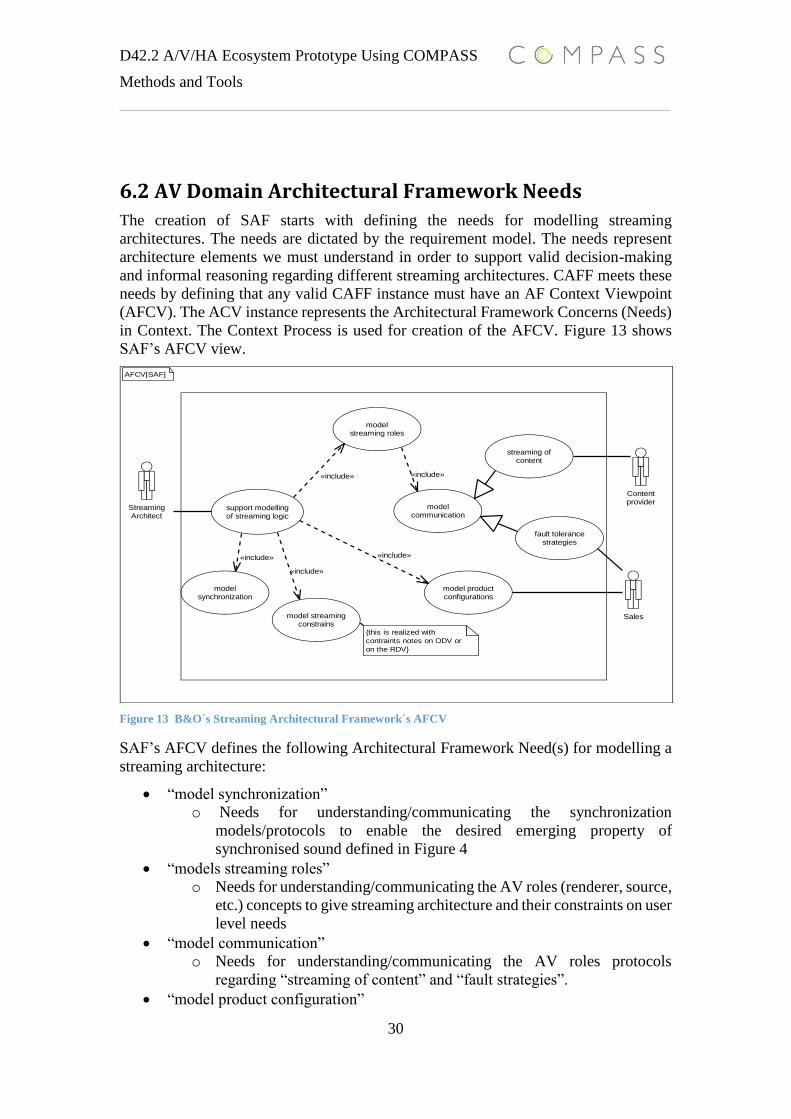
6.2 AV Domain Architectural Framework Needs
The creation of SAF starts with defining the needs for modelling streaming
architectures. The needs are dictated by the requirement model. The needs represent
architecture elements we must understand in order to support valid decision-making
and informal reasoning regarding different streaming architectures. CAFF meets these
needs by defining that any valid CAFF instance must have an AF Context Viewpoint
(AFCV). The ACV instance represents the Architectural Framework Concerns (Needs)
in Context. The Context Process is used for creation of the AFCV. Figure 13 shows
SAF’s AFCV view.
Figure 13 B&O´s Streaming Architectural Framework´s AFCV
SAF’s AFCV defines the following Architectural Framework Need(s) for modelling a
streaming architecture:
“model synchronization”
o Needs for understanding/communicating the synchronization
models/protocols to enable the desired emerging property of
synchronised sound defined in Figure 4
“models streaming roles”
o Needs for understanding/communicating the AV roles (renderer, source,
etc.) concepts to give streaming architecture and their constraints on user
level needs
“model communication”
o Needs for understanding/communicating the AV roles protocols
regarding “streaming of content” and “fault strategies”.
“model product configuration”
StreamingArchitect
Sales
Contentprovider
support modellingof streaming logic
model productconfigurations
modelstreaming roles
modelcommunication
modelsynchronization
streaming ofcontent
fault tolerancestrategies
model streamingconstrains
«include»
«include»
«include»
«include»
«include»
AFCV[SAF]
{this is realized with
contraints notes on ODV or
on the RDV}
D42.2 A/V/HA Ecosystem Prototype Using COMPASS
Methods and Tools
31
o Needs for understanding/communicating capabilities of product
configuration sets for a given CS’s architecture.
“model streaming constraints”
o Needs for giving semantics meaning to the AF’s View Point(s).
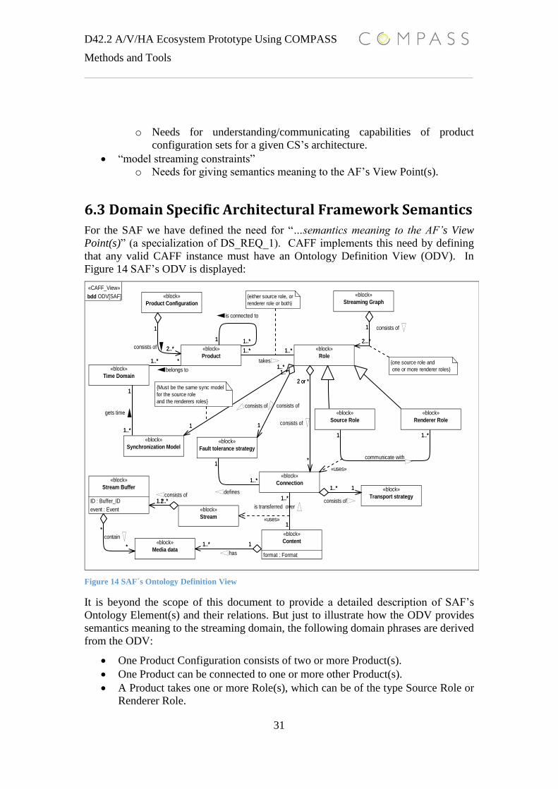
6.3 Domain Specific Architectural Framework Semantics
For the SAF we have defined the need for “…semantics meaning to the AF’s View
Point(s)” (a specialization of DS_REQ_1). CAFF implements this need by defining
that any valid CAFF instance must have an Ontology Definition View (ODV). In
Figure 14 SAF’s ODV is displayed:
Figure 14 SAF´s Ontology Definition View
It is beyond the scope of this document to provide a detailed description of SAF’s
Ontology Element(s) and their relations. But just to illustrate how the ODV provides
semantics meaning to the streaming domain, the following domain phrases are derived
from the ODV:
One Product Configuration consists of two or more Product(s).
One Product can be connected to one or more other Product(s).
A Product takes one or more Role(s), which can be of the type Source Role or
Renderer Role.
1 1..*
1..*1..*
2...*
1
2..*
1
1
1..*1..* *
1
1..*1
1..*
1..*1
*
2 or *
1
1..*
1..*
1
1..*1..*
1..* 1*
*
11..*
«CAFF_View»
bdd ODV[SAF]
«block»
Product
«block»
Role
«block»
Source Role
«block»
Renderer Role
«block»
Streaming Graph«block»
Product Configuration
«block»
Synchronization Model
«block»
Time Domain
«block»
Fault tolerance strategy
«block»
Connection
«block»
Content
format : Format
«block»
Stream
«block»
Stream Buffer
ID : Buffer_ID
event : Event
«block»
Media data
«block»
Transport strategy
1 1..*
is connected to
1..*1..*
takes
2...*
1 consists of
2..*
1
consists of
1
1..*
consists of
1..* *
belongs to
1
1..*
gets time
1
1..*
consists of
1..*1
communicate with*
2 or *
consists of
1
1..*
defines1..*
1
is transferred over1..*1..*
consists of
1..* 1
has*
*
contain
11..*
consists of
«uses»
«uses»
{either source role, or
renderer role or both}
{one source role and
one or more renderer roles}
{Must be the same sync model
for the source role
and the renderers roles}
D42.2 A/V/HA Ecosystem Prototype Using COMPASS
Methods and Tools
32
A Source Role communicates with one or more Renderer Role(s) using a
Connection.
A Connection uses one Transport Strategy.
Content(s) is transferred over a Connection(s) using a Stream(s).
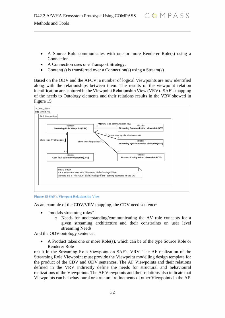
Based on the ODV and the AFCV, a number of logical Viewpoints are now identified
along with the relationships between them. The results of the viewpoint relation
identification are captured in the Viewpoint Relationship View (VRV). SAF’s mapping
of the needs to Ontology elements and their relations results in the VRV showed in
Figure 15.
Figure 15 SAF´s Viewport Relationship View
As an example of the CDV/VRV mapping, the CDV need sentence:
“models streaming roles”
o Needs for understanding/communicating the AV role concepts for a
given streaming architecture and their constraints on user level
streaming Needs
And the ODV ontology sentence:
A Product takes one or more Role(s), which can be of the type Source Role or
Renderer Role
result in the Streaming Role Viewpoint on SAF’s VRV. The AF realization of the
Streaming Role Viewpoint must provide the Viewpoint modelling design template for
the product of the CDV and ODV sentences. The AF Viewpoints and their relations
defined in the VRV indirectly define the needs for structural and behavioural
realizations of the Viewpoints. The AF Viewpoints and their relations also indicate that
Viewpoints can be behavioural or structural refinements of other Viewpoints in the AF.
1..* 1
1
1..*
1
1..*
1
1
«CAFF_View»
bdd VRV[SAF]
SAF Perspectives
«block»
Streaming Role Viewpoint (SRV)
«block»
Streaming Communication Viewpoint (SCV)
«block»
Com fault tolerance viewpoint(CFV)
«block»
Product Configuration Viewpoint (PCV)
«block»
Streaming synchronization Viewpoint(SSV)
«block»
Streaming Role Viewpoint (SRV)
«block»
Streaming Communication Viewpoint (SCV)
«block»
Com fault tolerance viewpoint(CFV)
«block»
Product Configuration Viewpoint (PCV)
«block»
Streaming synchronization Viewpoint(SSV)
1..* 1show roles communication flow
1
1..*
show roles for products
1
1..*
show roles FT strategies
1
1show roles synchronization model
This is a view!
it is a instance of the CAFF Viewpoint Relationships View.
therefore it is a "Viewpoint Relationships View" defining viewpoints for the SAF!

D42.2 A/V/HA Ecosystem Prototype Using COMPASS
Methods and Tools
33
In SAF’s VRV the relations between the Streaming Role viewpoint and the Streaming
communication Viewpoint states:
The Streaming communication Viewpoint shows roles communication flow for
the roles defined in the Streaming Role Viewpoint.
The relation represents a modelling requirement saying that the Streaming
Communication Viewpoint must be a behavioural refinement of the Streaming Role
Viewpoint. Hence the Streaming Role viewpoint must be a structural Viewpoint.
The VRV is a product of CDV and ODV elements, defining a set of needed AF
Viewpoints for describing the structural and behavioural aspect for a domain specific
architecture.
6.4 Architectural Framework View Point Definitions
Each Viewpoint of SAF is defined by a Viewpoint Context View (VCV), and a
Viewpoint Definition View (VDV). The VCVs are Use Cases(s) from the ACV and the
VDVs are the semantics for the VCVs using ODV’s elements. The AF Viewpoint pair
ensures needed traceability and Viewpoint instance consistency (satisfying DS_REQ_1
and DS_REQ_2). In Figure 16 the VCV for the SAF Product Configuration Viewpoint
are displayed.
Figure 16 Product Configuration VCV
The second element of the Product Configuration Viewpoint pair appears in Figure 17.
Sales
model productconfigurations
show product Show connectionbetween products
«include» «include»
Product configuration viewpoint

D42.2 A/V/HA Ecosystem Prototype Using COMPASS
Methods and Tools
34
Figure 17 Product Configuration Viewpoint VDV
The VDV for the Product Configuration Viewpoint contains the ODV elements stating
the relationships among products. The VDV also defines how product configuration
must be modelled. A product Configuration must be modelled as a package and the
relations between products must be modelled with an association. The VDVs give a
stronger semantics to the view instance, which enabled validation of correct models and
make viewpoint instances comparable.
6.5 SoS Architectural Pattern Languages
B&O uses a combination of COMPASS enabling patterns and frameworks [D22.3] for
SAF’s viewpoints. The architectural pattern languages approach that B&O has used is
well understood for component-based designs and can easily be re-used for CS/SoS-
level modelling. COMPASS supports this approach by providing architectural-level
design patterns and frameworks tailored for CS and SoS modelling.
The SAF is based on the following COMPASS-enabled patterns and frameworks:
The Integration Framework [D21.4]
The Fault Modelling Architectural Framework [D24.2]
The Contract Pattern [D22.3]
Since the Viewpoint’s VDVs are already defined for the COMPASS patterns and
framework themselves, this section will only show some SAF viewpoint instantiations.
For this purpose, the B&O proprietary Streaming framework NMM is used. NMM has
been fully modelled using SAF but only a simplified NMM view instance will be shown
in this document.
11
2..*1
1
1..*
«SAF_Viewpoint»
bdd VDV[ PCV]
«block»
PCV
«block»
Product Configuration
«block»
Product
11
consists of
2..*1consists of
1
1..*
is connected to
{must be modelled
with association }
{must be modelled
with package}
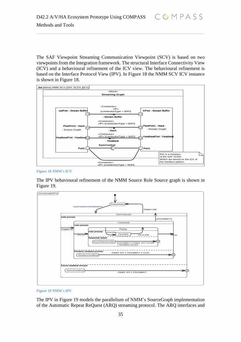
D42.2 A/V/HA Ecosystem Prototype Using COMPASS
Methods and Tools
35
The SAF Viewpoint Streaming Communication Viewpoint (SCV) is based on two
viewpoints from the Integration framework. The structural Interface Connectivity View
(ICV) and a behavioural refinement of the ICV view. The behavioural refinement is
based on the Interface Protocol View (IPV). In Figure 18 the NMM SCV ICV instance
is shown in Figure 18.
Figure 18 NMM’s ICV
The IPV behavioural refinement of the NMM Source Role Source graph is shown in
Figure 19.
Figure 19 NMM´s IPV
The IPV in Figure 19 models the parallelism of NMM’s SourceGraph implementation
of the Automatic Repeat ReQuest (ARQ) streaming protocol. The ARQ interfaces and
ibd [block] NMM SCV [SAF SCDV ][ICV]
«block»
Streaming Graph
: Render Graph
inPort : Stream Buffer
Port1
HeatbeatPort : Heatbeat
FlowPort1 : Nack
: Source Graph
outPort : Stream Buffer
HeatbeatPort : Heatbeat
FlowPort1 : Nack
Port1
: Render Graph
inPort : Stream Buffer
Port1
HeatbeatPort : Heatbeat
FlowPort1 : Nack
inPort : Stream Buffer
Port1
HeatbeatPort : Heatbeat
FlowPort1 : Nack
: Source Graph
outPort : Stream Buffer
HeatbeatPort : Heatbeat
FlowPort1 : Nack
Port1
outPort : Stream Buffer
HeatbeatPort : Heatbeat
FlowPort1 : Nack
Port1
SyncControl
: Stream Buffer
«Connector»«IP»
{connectionType = WIFI}
: Stream Buffer
«Connector»«IP» {connectionType = WIFI}
: Heatbeat
«Connector»«IP» {connectionType = WIFI}
: Heatbeat
: Nack
«Connector»«IP» {connectionType = WIFI}
: Nack
this is a instance
of the SAF SCDV.
Which are besed on the ICV of
the interface pattern
PowerDown
DisConnected
main process
Connected
main process
Playing
main process
PAUSED
Sequential State1
SourceNackHandler
Renderer heatbeat process
RendererHeatBeat
Source heatbeat process
SourceHeatBeat
SourceGraph(IPV)
PowerDown
DisConnected
main process
Connected
main process
Playing
main process
PAUSED
Sequential State1
SourceNackHandler
Renderer heatbeat process
RendererHeatBeat
Source heatbeat process
SourceHeatBeat
main process
Connected
main process
Playing
main process
PAUSED
Sequential State1
SourceNackHandler
Renderer heatbeat process
RendererHeatBeat
Connected
main process
Playing
main process
PAUSED
Sequential State1
SourceNackHandler
Renderer heatbeat process
RendererHeatBeat
main process
Playing
main process
PAUSED
Sequential State1
SourceNackHandler
Playing
main process
PAUSED
Sequential State1
SourceNackHandler
main process
PAUSEDPAUSED
Sequential State1
SourceNackHandlerSourceNackHandler
Renderer heatbeat process
RendererHeatBeat RendererHeatBeat
Source heatbeat process
SourceHeatBeat SourceHeatBeat
/
[sourceControlChannel*]/
/POWER_OFF || DISCONNECT
[POWER_OFF || DISCONNECT || Stop]/
[POWER_Off]/
[CONNECT]/
[DISCONNECT]/
/PLAY
[DISCONNECT||POWER_OFF||STOPP||RESUMED||PLAY]/
/Stop
/PAUSE
/RESUME
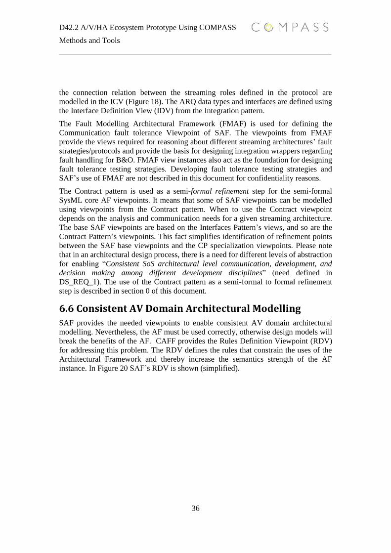
D42.2 A/V/HA Ecosystem Prototype Using COMPASS
Methods and Tools
36
the connection relation between the streaming roles defined in the protocol are
modelled in the ICV (Figure 18). The ARQ data types and interfaces are defined using
the Interface Definition View (IDV) from the Integration pattern.
The Fault Modelling Architectural Framework (FMAF) is used for defining the
Communication fault tolerance Viewpoint of SAF. The viewpoints from FMAF
provide the views required for reasoning about different streaming architectures’ fault
strategies/protocols and provide the basis for designing integration wrappers regarding
fault handling for B&O. FMAF view instances also act as the foundation for designing
fault tolerance testing strategies. Developing fault tolerance testing strategies and
SAF’s use of FMAF are not described in this document for confidentiality reasons.
The Contract pattern is used as a semi-formal refinement step for the semi-formal
SysML core AF viewpoints. It means that some of SAF viewpoints can be modelled
using viewpoints from the Contract pattern. When to use the Contract viewpoint
depends on the analysis and communication needs for a given streaming architecture.
The base SAF viewpoints are based on the Interfaces Pattern’s views, and so are the
Contract Pattern’s viewpoints. This fact simplifies identification of refinement points
between the SAF base viewpoints and the CP specialization viewpoints. Please note
that in an architectural design process, there is a need for different levels of abstraction
for enabling “Consistent SoS architectural level communication, development, and
decision making among different development disciplines” (need defined in
DS_REQ_1). The use of the Contract pattern as a semi-formal to formal refinement
step is described in section 0 of this document.
6.6 Consistent AV Domain Architectural Modelling
SAF provides the needed viewpoints to enable consistent AV domain architectural
modelling. Nevertheless, the AF must be used correctly, otherwise design models will
break the benefits of the AF. CAFF provides the Rules Definition Viewpoint (RDV)
for addressing this problem. The RDV defines the rules that constrain the uses of the
Architectural Framework and thereby increase the semantics strength of the AF
instance. In Figure 20 SAF’s RDV is shown (simplified).

D42.2 A/V/HA Ecosystem Prototype Using COMPASS
Methods and Tools
37
Figure 20 SAf´s RDV
The SAF_RULE(s) in the RDV defines those views that must appear in a valid
architectural SAF model instance and enforces the relations required among
architectural views. The SAF03 Rule states that for each SRV, at least one SFV must
be defined. This enforces the required architectural model views for satisfying the
communication needed for understanding all of the AV role’s fault protocols.
The use and development of the domain specific architectural framework SAF meets
B&O’s development process needs regarding:
o DS_REQ_1: Consistent SoS/CS architectural level communication,
development, and decision making among different development
disciplines
o DS_REQ_2: Capability of expressing and analyzing SoS models during
early design stages
6.7 Architectural Design Validation and Testing
The development process ontology in Figure 2 states the relationships between the
Requirement Model, Architectural Design Model and the Architectural Design Test
Model(s) as follows:
The Architectural Design Test Model(s), which are refinements of the
Requirement Model, validates the Architectural Design Model.
The relations are also represented by the DS_REQ_3 and DS_REQ_4 requirements
stating:
DS_REQ_4: Capability of validation and testing of conceptual design models
DS_REQ_3: Capability of identified areas of incompleteness or ambiguity in
informal system specifications during early design stages
«CAFF_View»
bdd [Package] Rule Definition View (RDV)
«block»«SAF_Rule» {SAF_Rule_Text = must have at least one view of each viewpoint in an architecture}
SAF01
«block»«SAF_Rule» {SAF_Rule_Text = For each SRV view, there must be at least one SCV view in a ...
SAF02
«block»«SAF_Rule» {SAF_Rule_Text = For each SRV view, there must at least one SFV view in an ...
SAF03
These are rules about the correct use of
the streaming Architectural framework!!!
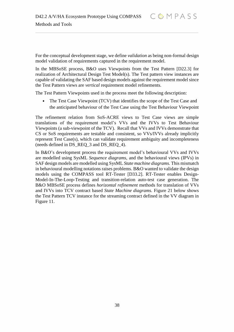
D42.2 A/V/HA Ecosystem Prototype Using COMPASS
Methods and Tools
38
For the conceptual development stage, we define validation as being non-formal design
model validation of requirements captured in the requirement model.
In the MBSoSE process, B&O uses Viewpoints from the Test Pattern [D22.3] for
realization of Architectural Design Test Model(s). The Test pattern view instances are
capable of validating the SAF based design models against the requirement model since
the Test Pattern views are vertical requirement model refinements.
The Test Pattern Viewpoints used in the process meet the following description:
• The Test Case Viewpoint (TCV) that identifies the scope of the Test Case and
the anticipated behaviour of the Test Case using the Test Behaviour Viewpoint
The refinement relation from SoS-ACRE views to Test Case views are simple
translations of the requirement model’s VVs and the IVVs to Test Behaviour
Viewpoints (a sub-viewpoint of the TCV). Recall that VVs and IVVs demonstrate that
CS or SoS requirements are testable and consistent, so VVs/IVVs already implicitly
represent Test Case(s), which can validate requirement ambiguity and incompleteness
(needs defined in DS_REQ_3 and DS_REQ_4).
In B&O’s development process the requirement model’s behavioural VVs and IVVs
are modelled using SysML Sequence diagrams, and the behavioural views (IPVs) in
SAF design models are modelled using SysML State machine diagrams. This mismatch
in behavioural modelling notations raises problems. B&O wanted to validate the design
models using the COMPASS tool RT-Tester [D33.2]. RT-Tester enables Design-
Model-In-The-Loop-Testing and transition-relation auto-test case generation. The
B&O MBSoSE process defines horizontal refinement methods for translation of VVs
and IVVs into TCV contract based State Machine diagrams. Figure 21 below shows
the Test Pattern TCV instance for the streaming contract defined in the VV diagram in
Figure 11.
D42.2 A/V/HA Ecosystem Prototype Using COMPASS
Methods and Tools
39
Figure 21 Test Pattern TCV instance
The Architectural Design Test Model(s) represent the SoS/CS Needs in the form of Test
Cases, therefore the Architectural Design Test Model can validate the Architectural
Design Model, which, until validated, are just a design proposition for the Needs.
7. Conceptual Stage Conclusion and Evaluation
Section 4, 5 and 6 have described how the COMPASS technology-based development
process enabled the production of the Need, Requirement Model, Architectural Design
Model and Architectural Test Design Model elements. The COMPASS technology has
met all of B&O’s needs for producing the models in the conceptual stage of the
MBSoSE development model. The development ontology descriptions for the
development model Figure 2 only describe the system (the blue elements) and
relationships. We can now justify a full description of the relationships for all the
ontology elements for the Conceptual Stage.
Disconnected Connected
StreamReady
Stopped
Playing
Init
StreamingLayer
Disconnected Connected
StreamReady
Stopped
Playing
Init
[init == true]/
[eventRequestNegated1(CONNECT)]/
stateError();
[eventRequest(SETUPSTREAM)]/
changeState(STREAM_READY);
[eventRequestNegated2(SETUPSTREAM, DISCONNECT)]/
stateError();
[eventRequest(DISCONNECT)]/
changeState(DISCONNECTED);
[eventRequest(DISCONNECT)]/
changeState(DISCONNECTED);
[eventRequest(DISCONNECT)]/
changeState(DISCONNECTED);
[eventRequest(STOP)]/
changeState(STOPPED);
[eventRequest(SETUPSTREAM)]/
changeState(STREAM_READY);
[eventRequestNegated2(SETUPSTREAM, DISCONNECT)]/
stateError();
[eventRequestNegated3(PLAY, DISCONNECT, SETUPSTREAM)]/
stateError();
[eventRequest(PLAY)]/
changeState(PLAYING);
[eventRequest(SETUPSTREAM)]/
changeState(STREAM_READY);
[eventRequestNegated2(STOP, DISCONNECT)]/
stateError();
[eventRequest(DISCONNECT)]/
changeState(DISCONNECTED);
[eventRequest(CONNECT)]/
changeState(CONNECTED);
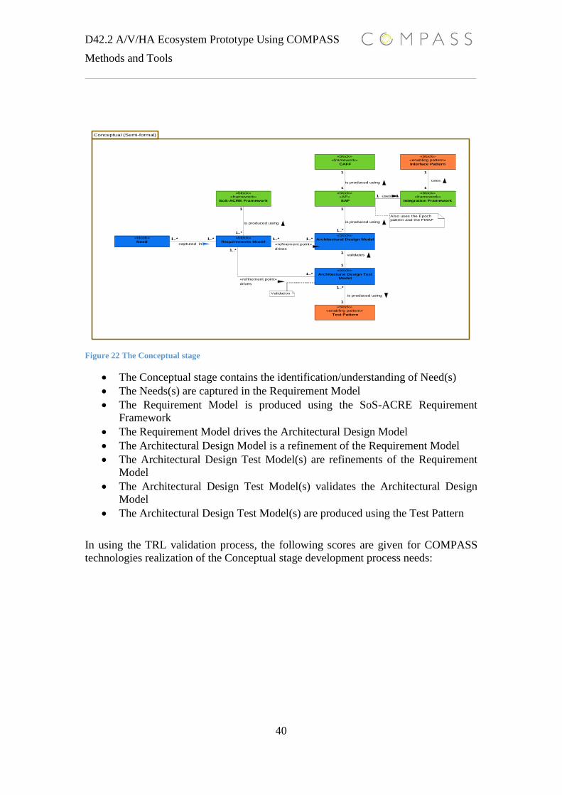
D42.2 A/V/HA Ecosystem Prototype Using COMPASS
Methods and Tools
40
Figure 22 The Conceptual stage
The Conceptual stage contains the identification/understanding of Need(s)
The Needs(s) are captured in the Requirement Model
The Requirement Model is produced using the SoS-ACRE Requirement
Framework
The Requirement Model drives the Architectural Design Model
The Architectural Design Model is a refinement of the Requirement Model
The Architectural Design Test Model(s) are refinements of the Requirement
Model
The Architectural Design Test Model(s) validates the Architectural Design
Model
The Architectural Design Test Model(s) are produced using the Test Pattern
In using the TRL validation process, the following scores are given for COMPASS
technologies realization of the Conceptual stage development process needs:
1..*1..* 1..*1..*
1
1
1..*
1..*
1
1..*
1
1..*
1
1..*
1
1
1
1
11
Conceptual (Semi-formal)
«block»«framework»
CAFF
«block»«enabling pattern»
Interface Pattern
«block»«framework»
Integration Framework
«block»«AF»
SAF
«block»«framework»
SoS-ACRE Framework
«block»«enabling pattern»
Test Pattern
«block»
Architectural Design Test
Model
«block»
Architectural Design Model«block»
Requirements Model
«block»
Need
«block»«framework»
CAFF
«block»«enabling pattern»
Interface Pattern
«block»«framework»
Integration Framework
«block»«AF»
SAF
«block»«framework»
SoS-ACRE Framework
«block»«enabling pattern»
Test Pattern
«block»
Architectural Design Test
Model
«block»
Architectural Design Model«block»
Requirements Model
«block»
Need1..*1..*
captured in
1..*1..*
«refinement point»
drives1
1
validates
1..*
1..*
«refinement point»
drives
1
1..*
is produced using
1
1..*
is produced using
1
1..*
is produced using
1
1
is produced using
1
1
uses
11 uses
Validation
Also uses the Epoch
pattern and the FMAF

41
Work Product Source
info
Need
defined
Validation
defined
Approach
Test
application
Case
study
Tailored
model
Applied
approach
TRL
SoS-ACRE DoW
D22.1
D21.1,
D41.1
D42.2
D21.1,
D42.2
D21.1 D42.2,
D21.6
D42.2
D21.6
7
CAFF DoW,
D22.1,
D21.2,
D21.5b
D42.2
D21.2,
D21.5b,
D42.2
D21.2
D21.5b
D24.2 D42.2
B&O
internal
document
B&O
quality
manual
9
Integration
Framework
DoW
D22.1
D21.4
D42.2
D21.4
D42.2
D21.4 D21.4 D42.2
D21.6
B&O
internal
document
B&O
quality
manual
9
Refinement
Framework
DoW,
D22.1
D22.5 D22.5
D42.2
D21.6 D22.5 D42.2 B&O
internal
document
B&O
quality
manual
9
Interface Pattern DoW,
D22.1
D22.3,
D22.6
D22.3
D22.6
D42.2
D21.4 (example use
in Integration
Framework)
D21.4 D42.2 B&O
internal
document
B&O
quality
manual
9
Test
Pattern
DoW,
D22.1
D22.3
D22.6
D22.3
D22.6
D22.3 D22.3 D42.2 B&O
internal
document
B&O
quality
manual
9
Contract
Pattern
DoW,
D22.1
D22.3
D22.6
D22.3
D22.6
D22.3 D22.3 D42.2 7

D42.2 A/V/HA Ecosystem Prototype Using COMPASS
Methods and Tools
42
Fault Modelling
Architectural
Framework
DoW, D24.2 D24.2 D24.2 D24.2 D42.2 7
Some notes regarding the TRL table:
The COMPASS methodologies applied at the conceptual stage reach TRL levels between seven and nine. The work products reaching TRL 9 are
deployed at B&O; where the work products reached TRL 7, they have been used on the case study by B&O. Both TRL 7 and 9 work products
have met B&Os needs. The evidence is the conceptual stages models produced and described in this section.
The tools used for producing the models have mostly been Artisan Studio. It is not within the scope of this evaluation to include a commercial
SysML tool such as Artisan Studio. The models described in this section could be realized using any communicational semi-formal notation.

43

44
The conceptual stage is about ensuring building the right system or understanding that
a system is right according needs. However, the development process must also
ensure/support the verification needs, stipulating: have we built the system correctly?
Alternatively, can we verify that a system is built correctly or that a system behaves
correctly?
The next section describes the formal stage of the COMPASS technology based
development process, and how COMPASS technology meets the formal stage’s
verification needs.
8. SoS Formal Modelling
This section will describe how formal COMPASS technologies are applied for
realization of the formal stage of the MBSoSE development process shown in Figure
2. The development process ontology relationships regarding refinements from the
conceptual stage to the formal stage, and the formal stage states:
The Formal stage contains one or more Architectural Design Specification
Model(s), which are driven by the Architectural Design Model. Architectural
Design Specification Model(s) can be a Model Checker Model or a Theory
Proving Model. The Architectural Design Specification Test Model verifies the
Architectural Design Specification Model(s).
The term verification in the formal stage means performing formal proofs (the transition
from a design model to a proven design model) and the terms proven model or verified
model mean: a model is verified or proven, if and only if there exists one or more
mathematical proofs that the model holds for some properties P. We define a proven
model to be an Architectural Design Specification Model, since an Architectural Design
Specification Model holds mathematical proofs for some specification S embedded in
the model.
8.1 Formal Motivations and Needs
From an industry point of view is important to be able to benefit from formal models
in the real world, meaning that taking the truth from the formal models is reflected in
the truth of the real SoS/CS environment. The industrial formal stage motivations are
formulated as:
“La mano kiu tenas la veron, povas puni la pekulon”
“The hand which holds the truth can punish the sinner”
The formal stage motivations imply the following concepts and tasks:
Find the truth
o Means verification of design models and includes:
Refinement from Architectural Design Specification Model(s) to
Architectural Design Specification Model(s)
Verifying that the refinement from Architectural Design
Model(s) to Architectural Design Specification Model(s) holds
Verifying the Architectural Design Specification Model for
some properties P
Use the truth (punish the sinner)
D42.2 A/V/HA Ecosystem Prototype Using COMPASS
Methods and Tools
45
o Architectural Design Specification Model holds the truth, meaning that
traces from the specifications of the Architectural Design Specification
Model can be used to verify, analyse or drive and CS/SoS
implementation of the Architectural Design Specification Model in the
Real stage. The tasks and realization of the use the truth concepts are
described in the Real stage section of this document.
Therefore one of the main purposes of the formal stage is design model verification.
Architectural Design Model(s) are only validated against the Requirement Model at a
conceptual level. Architectural Design Model(s) might not hold the truth according to
properties implicitly defined in the requirements at a more technical level. Revisiting
two of the design stages development needs from B&O, which state:
DS_REQ_4: Capability of validation and testing of conceptual design models
DS_REQ_3: Capability of identified areas of incompleteness or ambiguity in
informal system specifications during early design stages
we redefine these needs to formal-stage needs based on the formal stage definitions and
the formal motivation:
FS_REQ_1: Capability of refinement from conceptual design models to formal
specification models
FS_REQ_2: Capability of testing formal specification models
FS_REQ_3: Verification capability regarding identified areas of
incompleteness or ambiguity in informal system specifications (conceptual
design models) during early design stages
8.2 Design Model to Design Specification Refinement
COMPASS provides several solutions for addressing the design model to design
specification refinement model needs described in FS_REQ_1. As briefly mentioned
in the conceptual stage descriptions, the AV domain specific architectural SAF uses the
Contact Pattern [D22.3] as a first step in the translation of the Architectural Design
Model to Architectural Design Specification Models. The Contract Pattern is intended
as an aid for formal definitions of contracts. The contract definitions form the base for
further formal verification. The implicit contracts of the SAF Viewpoints instance have
been given a stronger semantics through explicit contract definitions using refinement
to Contract Pattern (CP) views. Some examples of the horizontal viewpoint refinements
points between SAF views and CP views are:
The SAF Viewpoint Streaming Communication Viewpoint (SCV) is refined to the CP’s
Contract Definition Viewpoint (CDV) stating:
The Contract Definition Viewpoint is used for the definition of Contracts in
terms of their state variables, state invariants and operations they may provide.
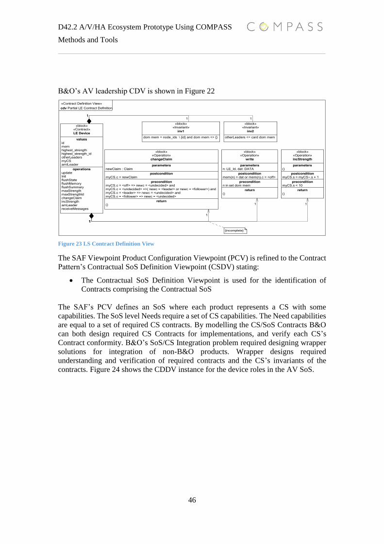
D42.2 A/V/HA Ecosystem Prototype Using COMPASS
Methods and Tools
46
B&O’s AV leadership CDV is shown in Figure 22
Figure 23 LS Contract Definition View
The SAF Viewpoint Product Configuration Viewpoint (PCV) is refined to the Contract
Pattern’s Contractual SoS Definition Viewpoint (CSDV) stating:
The Contractual SoS Definition Viewpoint is used for the identification of
Contracts comprising the Contractual SoS
The SAF’s PCV defines an SoS where each product represents a CS with some
capabilities. The SoS level Needs require a set of CS capabilities. The Need capabilities
are equal to a set of required CS contracts. By modelling the CS/SoS Contracts B&O
can both design required CS Contracts for implementations, and verify each CS’s
Contract conformity. B&O’s SoS/CS Integration problem required designing wrapper
solutions for integration of non-B&O products. Wrapper designs required
understanding and verification of required contracts and the CS’s invariants of the
contracts. Figure 24 shows the CDDV instance for the device roles in the AV SoS.
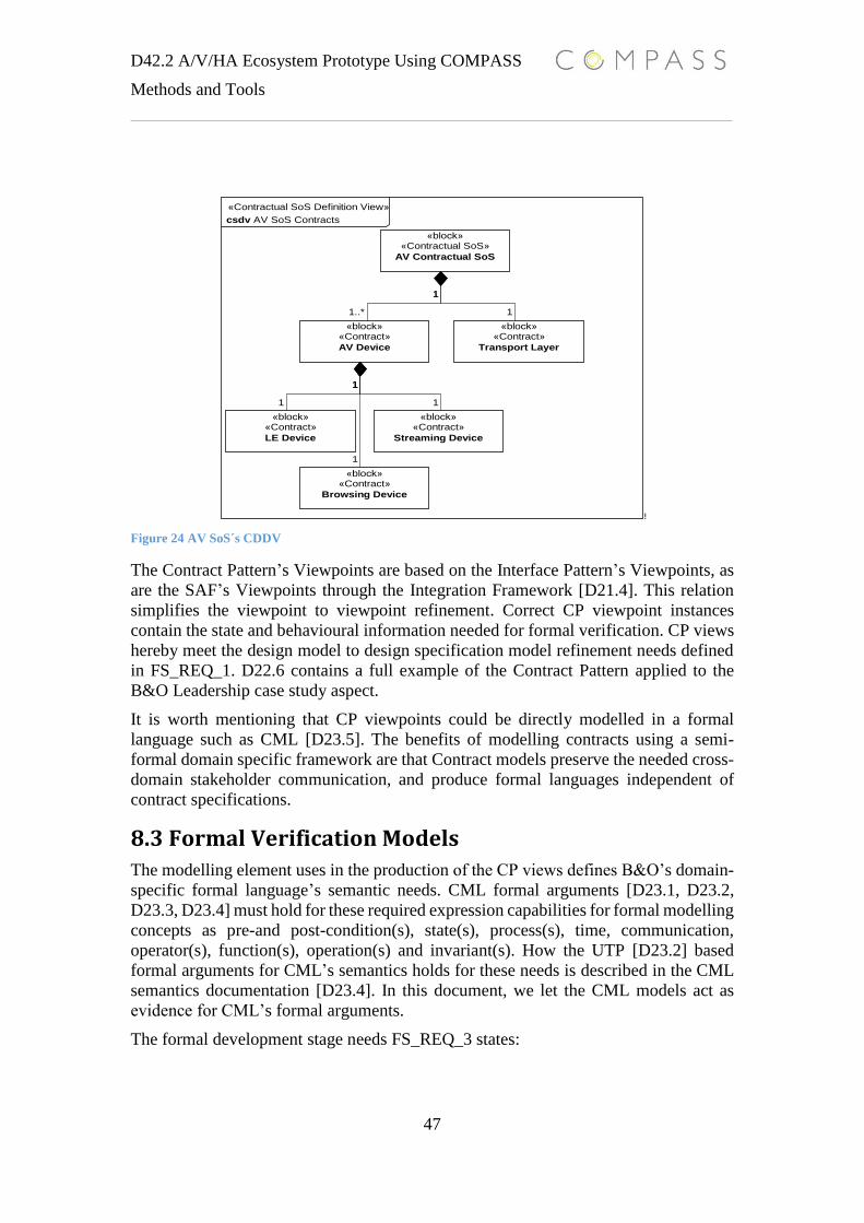
D42.2 A/V/HA Ecosystem Prototype Using COMPASS
Methods and Tools
47
Figure 24 AV SoS´s CDDV
The Contract Pattern’s Viewpoints are based on the Interface Pattern’s Viewpoints, as
are the SAF’s Viewpoints through the Integration Framework [D21.4]. This relation
simplifies the viewpoint to viewpoint refinement. Correct CP viewpoint instances
contain the state and behavioural information needed for formal verification. CP views
hereby meet the design model to design specification model refinement needs defined
in FS_REQ_1. D22.6 contains a full example of the Contract Pattern applied to the
B&O Leadership case study aspect.
It is worth mentioning that CP viewpoints could be directly modelled in a formal
language such as CML [D23.5]. The benefits of modelling contracts using a semi-
formal domain specific framework are that Contract models preserve the needed cross-
domain stakeholder communication, and produce formal languages independent of
contract specifications.
8.3 Formal Verification Models
The modelling element uses in the production of the CP views defines B&O’s domain-
specific formal language’s semantic needs. CML formal arguments [D23.1, D23.2,
D23.3, D23.4] must hold for these required expression capabilities for formal modelling
concepts as pre-and post-condition(s), state(s), process(s), time, communication,
operator(s), function(s), operation(s) and invariant(s). How the UTP [D23.2] based
formal arguments for CML’s semantics holds for these needs is described in the CML
semantics documentation [D23.4]. In this document, we let the CML models act as
evidence for CML’s formal arguments.
The formal development stage needs FS_REQ_3 states:
!
!
!
1
1
1
1
1
1
1
1
1..*
1
«Contractual SoS Definition View»
csdv AV SoS Contracts
«block»«Contractual SoS»
AV Contractual SoS
«block»«Contract»
LE Device
«block»«Contract»
Transport Layer
«block»«Contract»
Browsing Device
«block»«Contract»
Streaming Device
«block»«Contract»
AV Device
1
1
1
1
1
1
1
1
1..*
1

D42.2 A/V/HA Ecosystem Prototype Using COMPASS
Methods and Tools
48
FS_REQ_3: Verification capability regarding identified areas of
incompleteness or ambiguity in informal system specifications (conceptual
design models) during early design stages
Architectural Design Specification Models are produced based on contract verification
needs. Recall that a specification model M must hold for some property P. The
Contracts for M defines P, and P defines the needed verification of M, so M holds for
P. The Contracts for M also indicate the modelling style and tools for M for enabled
verification of P. COMPASS provides several tools and guidelines for meeting
verification needs. The Development process ontology contains three main
Architectural Design Specification Models with the following verification needs
meaning and relations:
The Architectural Design Specification Model (ASPM)
o The base ASPM is used for simulation of M’s completeness of P. The
verification of M is enabled by the Symphony interpreter/debugger plug-
ins [D32.2] and CML’s formal semantics [D23.4].
The Model Checker Model (MCM)
o The MCM is a specialization of the ASPM model and extends M’s
verification of P with model-checker verification of P. The verification
of M is enabled by the Symphony Formula plug-in [D33.1] and CML’s
formal model-checkable properties.
The Theory Proving Model (TPM)
o The TPM is a specialization of the ASPM model and extends M’s
verification of P with a theorem-proved verification of P. The
verification of M is enabled by the Symphony Isabelle-HOL and proof
obligation plug-ins [D33.2] and CML’s formal semantics in UTP.
Often a set of different Architectural Design Specification models is needed for
complete verification of P. As an example of how COMPASS technology can enable
modelling and verification of Architectural Design Specification Models, this section
will show the TPM and MCM CML models for the CS SourceGraph contracts. The
high-level contracts of the Source graph interface state:
SG_Contract_1: “A valid interface implementation must always reply to a
request”.
o The communication protocol is a request-reply protocol, aimed at
handling distributed state consistency between source and control layer
CSs in the AV SoS.
SG_Contract_2: “if a state transition fails, a valid interface implementation
stays in the current state (a well-known state)”.
o Defines the error semantics of the protocol for ensuring distributed state
consistency.
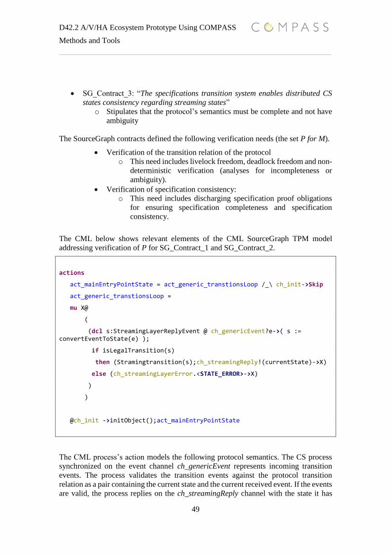
D42.2 A/V/HA Ecosystem Prototype Using COMPASS
Methods and Tools
49
SG_Contract_3: “The specifications transition system enables distributed CS
states consistency regarding streaming states”
o Stipulates that the protocol’s semantics must be complete and not have
ambiguity
The SourceGraph contracts defined the following verification needs (the set P for M).
Verification of the transition relation of the protocol
o This need includes livelock freedom, deadlock freedom and non-
deterministic verification (analyses for incompleteness or
ambiguity).
Verification of specification consistency:
o This need includes discharging specification proof obligations
for ensuring specification completeness and specification
consistency.
The CML below shows relevant elements of the CML SourceGraph TPM model
addressing verification of P for SG_Contract_1 and SG_Contract_2.
actions
act_mainEntryPointState = act_generic_transtionsLoop /_\ ch_init->Skip
act_generic_transtionsLoop =
mu X@
(
(dcl s:StreamingLayerReplyEvent @ ch_genericEvent?e->( s := convertEventToState(e) );
if isLegalTransition(s)
then (Stramingtransition(s);ch_streamingReply!(currentState)->X)
else (ch_streamingLayerError.<STATE_ERROR>->X)
)
)
@ch_init ->initObject();act_mainEntryPointState
The CML process’s action models the following protocol semantics. The CS process
synchronized on the event channel ch_genericEvent represents incoming transition
events. The process validates the transition events against the protocol transition
relation as a pair containing the current state and the current received event. If the events
are valid, the process replies on the ch_streamingReply channel with the state it has

D42.2 A/V/HA Ecosystem Prototype Using COMPASS
Methods and Tools
50
transited to. If the events are not valid according to the transition relation, the process
replies on the ch_streamingLayerError channel and it remains in its current state. This
part of the model covers the specification of request-reply and error protocol
communication semantics.
To ensure completeness and specification consistency the TPM model explicitly
defines P as operations with pre- and post condition and states with invariants. The
operations and states relevant for verification of the protocol completeness of P are
shown below:
state
transitionMap: map StreamingLayerReplyEvent to TransitionSet :=
{ cid |-> {} | cid in set transitionEventSet }
inv dom transitionMap = transitionEventSet and dom transitionMap <> {}
currentState:StreamingLayerReplyEvent := <DISCONNECTED>
inv currentState in set transitionEventSet
operations
initObject:()==>()
initObject() ==
(
transitionMap(<CONNECTED>):= { <DISCONNECTED>};
transitionMap(<DISCONNECTED>):=
{<CONNECTED>,<STREAM_READY>,<PLAYING>,<STOPPED>};
transitionMap(<STREAM_READY>):= {<CONNECTED>,<STREAM_READY>,<STOPPED>} ;
transitionMap(<PLAYING>):= {<STREAM_READY>};
transitionMap(<STOPPED>):= {<PLAYING>}
)
isLegalTransition:StreamingLayerReplyEvent ==>bool
isLegalTransition(evt)==
(
return evt in set transitionEventSet and card {x|x in set dom
transitionMap @ evt = x and currentState in set transitionMap(x)}> 0
)

D42.2 A/V/HA Ecosystem Prototype Using COMPASS
Methods and Tools
51
Stramingtransition:StreamingLayerReplyEvent ==>()
Stramingtransition(evt)==
(
currentState := evt
)
pre evt in set transitionEventSet and
card {x|x in set dom transitionMap @ evt = x and
currentState in set transitionMap(x)}> 0
post currentState = evt
The verification of P is carried out by running the Symphony Isabelle-HOL/proof
obligation plug-ins. The proof obligations for P are generated and auto-discharged by
Isabelle. The result is a proven design specification for the property set P. A full
description of the verification of the TPM model using the Symphony Isabelle-
HOL/proof obligation plug-ins can be found in D33.2
TPM models are mostly based on CML’s VDM state and operation semantics, and
cannot generate proof for the CSP semantics of CML. TPM models can therefore not
verify properties such as livelock freedom, deadlock freedom and non-determinism.
These properties are required for the verification of the transition relation of the
SourceGraph protocol as stated in SG_Contract_3. Hence the specification
completeness of the TPM SourceGraph model depends on the completeness of the
protocol transition relation. For completeness verification of P for the SourceGraph
protocol contracts, an MVM CML model was produced. Below the main protocol
process for the SourceGraph MCM CML model is shown:
actions
-- action for starting the main product statemachine, can be interupted by a sync on the ch_init channel
act_mainEntryPointState = act_processLoop /_\ ch_init->Skip
-- main product state machine action. Offer events based on the current state of the product
act_processLoop =
(
[currentState <> <DISCONNECTED> ]& act_disconnect -- most always offer to
disconnect after the product is connected
[]
[currentState = <CONNECTED> or currentState = <STOPPED>]& act_connected –
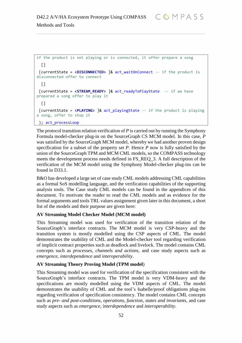
D42.2 A/V/HA Ecosystem Prototype Using COMPASS
Methods and Tools
52
if the product is not playing or is connected, it offer prepare a song
[]
[currentState = <DISCONNECTED> ]& act_waitOnConnect -- if the product is disconnected offer to connect
[]
[currentState = <STREAM_READY> ]& act_readyToPlayState -- if we have prepared a song offer to play it
[]
[currentState = <PLAYING> ]& act_playingState -- if the product is playing a song, offer to stop it
); act_processLoop
The protocol transition relation verification of P is carried out by running the Symphony
Formula model-checker plug-in on the SourceGraph CS MCM model. In this case, P
was satisfied by the SourceGraph MCM model, whereby we had another proven design
specification for a subset of the property set P. Hence P now is fully satisfied by the
union of the SourceGraph TPM and MCM CML models, so the COMPASS technology
meets the development process needs defined in FS_REQ_3. A full description of the
verification of the MCM model using the Symphony Model-checker plug-ins can be
found in D33.1.
B&O has developed a large set of case study CML models addressing CML capabilities
as a formal SoS modelling language, and the verification capabilities of the supporting
analysis tools. The Case study CML models can be found in the appendices of this
document. To motivate the reader to read the CML models and as evidence for the
formal arguments and tools TRL values assignment given later in this document, a short
list of the models and their purpose are given here:
AV Streaming Model Checker Model (MCM model)
This Streaming model was used for verification of the transition relation of the
SourceGraph’s interface contracts. The MCM model is very CSP-heavy and the
transition system is mostly modelled using the CSP aspects of CML. The model
demonstrates the usability of CML and the Model-checker tool regarding verification
of implicit contract properties such as deadlock and livelock. The model contains CML
concepts such as processes, channels and actions, and case study aspects such as
emergence, interdependence and interoperability.
AV Streaming Theory Proving Model (TPM model)
This Streaming model was used for verification of the specification consistent with the
SourceGraph’s interface contracts. The TPM model is very VDM-heavy and the
specifications are mostly modelled using the VDM aspects of CML. The model
demonstrates the usability of CML and the tool’s Isabelle/proof obligations plug-ins
regarding verification of specification consistency. The model contains CML concepts
such as pre- and post-conditions, operations, function, states and invariants, and case
study aspects such as emergence, interdependence and interoperability.

D42.2 A/V/HA Ecosystem Prototype Using COMPASS
Methods and Tools
53
Emergent Leadership Architectural Design Specification Model (ASPM model)
This ASPM model was used for developing and validation of the LS protocol. The
model can be simulated and the desired emergent behaviour can be validated, despite
the dynamicity of behaviour in the SoS. The model is considered a pure CML model.
The model shows the use of CML language constructs and Symphony debugger
capabilities for enabled validation of the B&O LS protocol. The model contains CML
concepts such as pre- and post-conditions, operations, functions, states, processes,
channels, actions invariants, and case study aspects such as emergence,
interdependence, interoperability, dynamicity and distribution.
Timed Transport Layer Architectural Design Specification Model (ADSM model)
The ADSM model was used to validate the time capabilities of CML and the Symphony
tool. In both the AV Streaming and Leadership case study aspects, there is a need for
modelling and simulating time. This model shows the use of the CML time semantics
for modelling the behavioural aspects of timed multicast in an IP network. The model
contains both time domain, network, source and renderer processes. All CML processes
use, and are affected by, time. The model contains CML concepts such as pre- and post-
conditions, operations, function, states, processes, channels, actions invariants, and
case study aspects such as interdependence, interoperability, dynamicity and
distribution.
OO CML Design Pattern Model
This model was used to validate the object oriented part of CML. The model applied a
set of standard design patterns to the OO part and introduced a design pattern for
modelling reusable CML processes. The Case study aspects used for the model are the
network reader/writer communication between CSs. The model contains CML concepts
such as classes, inheritance, overwriting operation, dynamic and static binding, states,
processes, channels, actions and case study aspects such as interoperability and
dynamicity.
OO Clock Domain Model
This model shows the uses of the CML OO design pattern described above applied to
OO modelling CS clock domains. The model contains an OO framework for modelling
clocks. To add a new Clock domain to the SoS, the model developer needs only create
a subclass of a base Clock class and add the new class to a clock factory. The Clocks’
communication semantics are provided by the frameworks processes. The models
contain CML concepts such as classes, inheritance, overwriting operation, dynamic
and static binding, states, processes, channels, actions and case study aspects such as
interdependence, interoperability, dynamicity and distribution.
SoS AV Device Discovery Architectural Design Specification Model (ADSM)
This Device Discovery CML model represents some SoS aspects of the control layer
(CL) part of the B&O AV Architecture. The CL is the top layer that the user interacts
with using a local control interface (hence the term control layer). The CL part of the
AV Architecture has the following responsibilities:
D42.2 A/V/HA Ecosystem Prototype Using COMPASS
Methods and Tools
54
Responsible for device discovery and device management
Responsible for service discovery and service management
Responsible for connectivity between remote and local services
Responsible for event propagation between local and remote services
The Device Discovery model represents the communication protocols between the
announcement- and discovery processes in an IP network. Device Discovery (DD)
refers to the process of identifying devices present on a network. The DD abstraction
contains two logical mechanisms and processes:
device announcement mechanism (DAM)
device discovery mechanism (DDM (uses DAM))
The CML processes in the model are based on the Interface Protocol View (PDV) from
the COMPASS Interface pattern [D22.3]. In the model each CML process represents
one PDV and one PDV represents an AV Control Layer product. The model contains
CML concepts such as pre- and post-conditions, operations, function, states, processes,
channels, actions invariants, and case study aspects such as emergence,
interdependence, interoperability, dynamicity and distribution.
8.4 Testing Formal Specification Models
The formal stage FS_REQ_2 Need stipulates the “capability of testing formal
specification models”. FS_REQ_2 represents the development model’s ontology
elements relationships: Architectural Design Specification Test Models verifies the
Architectural Design Specification Models. FS_REQ_2 is also derived from the formal
“find the truth” motivation stipulating Verifying the refinement from Architectural
Design Models to Architectural Design Specification Models. Recall that the
Architectural Design Models have been validated against the Requirement Model using
the Architectural Design Test Model. Architectural Design Specification Models must
also be validated against the Requirement Models ensuring the refinement preserves
the validity from the Architectural Design Model. The Architectural Design
Specification Test Model is a refinement of the Architectural Design Test Model
tailored for requirement validation and verification of the Architectural Design
Specification Model instance. Once again, the COMPASS Test pattern [D22.3] is used
for development of Architectural Design Specification Test Models. The Test Pattern
addresses development of a full V&V campaign for a given development process. The
Architectural Design Test Models only use the validation concepts from the Test
Pattern, where Architectural Design Specification Test Models represent the
verification concepts from the Test Pattern.
The refinement points between the Test Pattern views depend on the semantics of the
Architectural Design Specification Model. Architectural Design Specification Test
Models are developed based on the semantics of both the Architectural Design
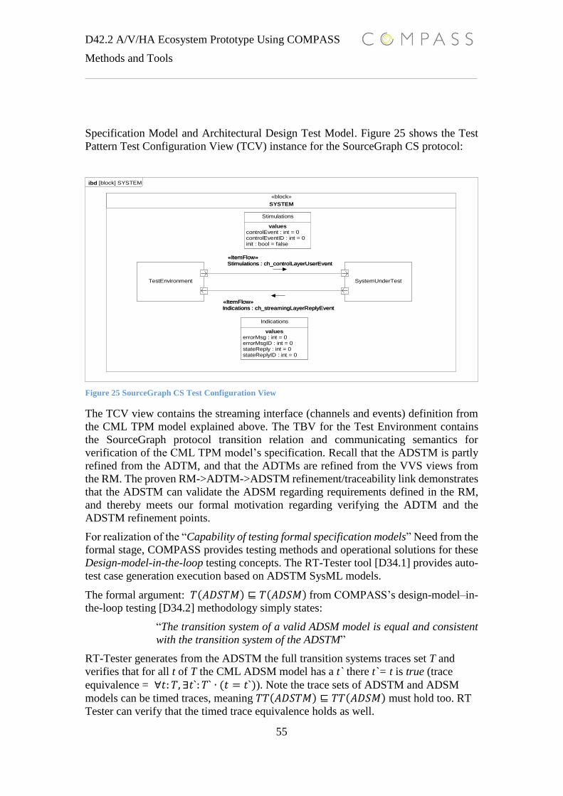
D42.2 A/V/HA Ecosystem Prototype Using COMPASS
Methods and Tools
55
Specification Model and Architectural Design Test Model. Figure 25 shows the Test
Pattern Test Configuration View (TCV) instance for the SourceGraph CS protocol:
Figure 25 SourceGraph CS Test Configuration View
The TCV view contains the streaming interface (channels and events) definition from
the CML TPM model explained above. The TBV for the Test Environment contains
the SourceGraph protocol transition relation and communicating semantics for
verification of the CML TPM model’s specification. Recall that the ADSTM is partly
refined from the ADTM, and that the ADTMs are refined from the VVS views from
the RM. The proven RM->ADTM->ADSTM refinement/traceability link demonstrates
that the ADSTM can validate the ADSM regarding requirements defined in the RM,
and thereby meets our formal motivation regarding verifying the ADTM and the
ADSTM refinement points.
For realization of the “Capability of testing formal specification models” Need from the
formal stage, COMPASS provides testing methods and operational solutions for these
Design-model-in-the-loop testing concepts. The RT-Tester tool [D34.1] provides auto-
test case generation execution based on ADSTM SysML models.
The formal argument: 𝑇(𝐴𝐷𝑆𝑇𝑀) ⊑ 𝑇(𝐴𝐷𝑆𝑀) from COMPASS’s design-model–in-
the-loop testing [D34.2] methodology simply states:
“The transition system of a valid ADSM model is equal and consistent
with the transition system of the ADSTM”
RT-Tester generates from the ADSTM the full transition systems traces set T and
verifies that for all t of T the CML ADSM model has a t` there t`= t is true (trace
equivalence = ∀𝑡: 𝑇, ∃𝑡`: 𝑇` ∙ (𝑡 = 𝑡`)). Note the trace sets of ADSTM and ADSM
models can be timed traces, meaning 𝑇𝑇(𝐴𝐷𝑆𝑇𝑀) ⊑ 𝑇𝑇(𝐴𝐷𝑆𝑀) must hold too. RT
Tester can verify that the timed trace equivalence holds as well.
ibd [block] SYSTEM
«block»
SYSTEM
TestEnvironment SystemUnderTest
Indications
valueserrorMsg : int = 0errorMsgID : int = 0stateReply : int = 0stateReplyID : int = 0
Stimulations
valuescontrolEvent : int = 0controlEventID : int = 0init : bool = false
TestEnvironment SystemUnderTest
Indications
valueserrorMsg : int = 0errorMsgID : int = 0stateReply : int = 0stateReplyID : int = 0
Stimulations
valuescontrolEvent : int = 0controlEventID : int = 0init : bool = false
Indications : ch_streamingLayerReplyEvent
«ItemFlow»
Indications : ch_streamingLayerReplyEvent
«ItemFlow»
Stimulations : ch_controlLayerUserEvent
«ItemFlow»
Stimulations : ch_controlLayerUserEvent
«ItemFlow»
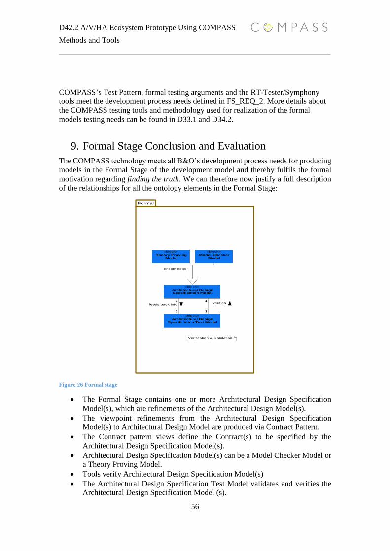
D42.2 A/V/HA Ecosystem Prototype Using COMPASS
Methods and Tools
56
COMPASS’s Test Pattern, formal testing arguments and the RT-Tester/Symphony
tools meet the development process needs defined in FS_REQ_2. More details about
the COMPASS testing tools and methodology used for realization of the formal
models testing needs can be found in D33.1 and D34.2.
9. Formal Stage Conclusion and Evaluation
The COMPASS technology meets all B&O’s development process needs for producing
models in the Formal Stage of the development model and thereby fulfils the formal
motivation regarding finding the truth. We can therefore now justify a full description
of the relationships for all the ontology elements in the Formal Stage:
Figure 26 Formal stage
The Formal Stage contains one or more Architectural Design Specification
Model(s), which are refinements of the Architectural Design Model(s).
The viewpoint refinements from the Architectural Design Specification
Model(s) to Architectural Design Model are produced via Contract Pattern.
The Contract pattern views define the Contract(s) to be specified by the
Architectural Design Specification Model(s).
Architectural Design Specification Model(s) can be a Model Checker Model or
a Theory Proving Model.
Tools verify Architectural Design Specification Model(s)
The Architectural Design Specification Test Model validates and verifies the
Architectural Design Specification Model (s).
1
11
1
Formal
«block»
Theory Proving
Model
«block»
Model-Checker
Model
«block»
Architectural Design
Specification Model
«block»
Architectural Design
Specification Test Model
«block»
Theory Proving
Model
«block»
Model-Checker
Model
«block»
Architectural Design
Specification Model
«block»
Architectural Design
Specification Test Model
1
1
verifies
1
1
feeds back into
{incomplete}
Verification & Validation
D42.2 A/V/HA Ecosystem Prototype Using COMPASS
Methods and Tools
57
The Architectural Design Specification Test Model is produced using the
Architectural Design Test Model, and contractual elements from Architectural
Design Specification Model(s).
Using the TRL validation process, the following scores are given for COMPASS
technologies’ realization of the Formal Stage’s development process needs. The TRL
evaluations are divided into two tables, one for the formal COMPASS methodologies
and one for the tools realization of those formal methodologies.
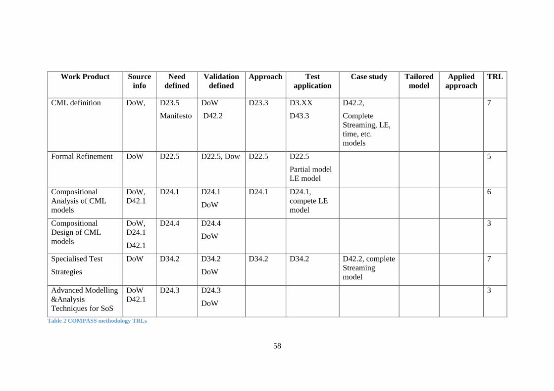
58
Work Product Source
info
Need
defined
Validation
defined
Approach
Test
application
Case study Tailored
model
Applied
approach
TRL
CML definition
DoW, D23.5
Manifesto
DoW
D42.2
D23.3 D3.XX
D43.3
D42.2,
Complete
Streaming, LE,
time, etc.
models
7
Formal Refinement DoW D22.5 D22.5, Dow D22.5 D22.5
Partial model
LE model
5
Compositional
Analysis of CML
models
DoW,
D42.1
D24.1 D24.1
DoW
D24.1 D24.1,
compete LE
model
6
Compositional
Design of CML
models
DoW,
D24.1
D42.1
D24.4 D24.4
DoW
3
Specialised Test
Strategies
DoW D34.2 D34.2
DoW
D34.2 D34.2 D42.2, complete
Streaming
model
7
Advanced Modelling
&Analysis
Techniques for SoS
DoW
D42.1
D24.3 D24.3
DoW
3
Table 2 COMPASS methodology TRLs

59
Work Product Source
info
Need
defined
Validation
defined
Approach
Test
application
Case
study
Tailored
model
Applied
approach
TRL
Symphony
Interpreter/debugger
(Simulator for CML)
DoW D23.5
D32.2
D32.2
D42.2
DoW
D32.2 D3.XX D42.2, 5
Symphony Model Checker
Plug-in
DoW D33.1 D33.1
Dow
D33.1 D33.1
D42.2 5
Symphony Proof Obligation
& theory proving
Plug-in(s)
DoW, D32.2 D32.2
DoW
D32.2 D32.2 D42.2 5
Symphony
RT-Tester
plug-in
DoW, D34.1 D34.1
DoW
D34.1 D34.1 D42.2 B&O
internal
document
B&O
quality
manual
9
Table 3 COMPASS tool TRLs

60
Some notes regarding the formal COMPASS methodology and tool TRL table:
The table contains some TRL results that are not described in this document.
Throughout the COMPASS project, B&O has worked closely with several of the
technology providers to ensure development of industrially applicable SoS technology.
The TRL evidence can therefore be found in the relevant project deliverables for those
COMPASS technologies. This document focuses on models which have been
developed by B&O without help from academic partners.
Summarising the content of these two tables, the message is quite clear: the COMPASS
formal technology provides theoretical solutions for industry’s SoS needs. The
operational part of using the formal theories in the form of tools is not currently industry
deployable however. The tools need a higher level of maturity and the documentation
must be more targeted to the level of industry knowledge and need. The CML semantics
documents are not CML industrial modelling guidelines. The CML modelling
guidelines provided so far are too limited and constrained for practical use. Generally,
the tool documentation is too incomplete and too error prone to enable correct use of
the tools from an industrial point of view.
The TRLs for most of the tools cannot reach higher than 5. The tools have been applied
to elements of the B&O case study, which should score a TRL of 7. However, in the
process of working with the tool one finds that in some cases the desired results are not
obtained. Therefore, the evidence does not justify a TRL value of 7. Only partial results
are achieved. Partial results can only give a TRL value of 5 according to the TRL
method. The RT-Tester tool is the most mature and industrially deployable tool. RT-
Tester benefits from having already been industrially deployed and having
documentation targeting industry. RT-Tester has been successfully deployed at B&O
and therefore scores a TRL value of 9.
There is one Formal Stage ontology relation that has not been covered in this section.
It is the relation saying:
Architectural Design Specification Test Model(s) are created from elements
(traces, proofs, contracts) of a proven Architectural Design Specification
Model.
This relation is described in the Real stage section because of its close relation to
verification of real CS implementation concepts and creation of test modes from proven
model traces.
The next section describes the Real stage of the development process and COMPASS
technology applicability for Real-stage needs.
10. SoS Co-Simulation and Testing
The Real stage’s ontology elements and relationships in Figure 2 state: the Real stage
contains B&O Product(s), which are specializations of the COMPASS ontology
concept System. Product(s) consist of Software System(s) and Hardware System(s).
Product(s) can be generated from an Architectural Design Specification Model or be
analysed by an Architectural Design Specification Model. Product(s) are verified by
Architectural Design Specification Test Model(s). The formal motivation concepts Use
the truth are implicitly stated in these ontology relations. COMPASS technology must
enable specification verification and specification refinement between the proven

D42.2 A/V/HA Ecosystem Prototype Using COMPASS
Methods and Tools
61
models and the real CSs. The requirements for the specification verification and
specification refinement are:
RS_REQ_1: Capabilities of using a formal specification to drive the
development of a new CS/SoS
RS_REQ_2: Capabilities of verifying a CS/SoS based on a formal
specification
10.1 Formal Specifications Models and SoS Target Development Environment Refinement
COMPASS addresses RS_REQ_1 with the COMPASS Refinement Framework
[D22.5]. The Architectural Design Specification Model M contains the truth for all
properties P for the contracts of M. The contract elements and the semantics of M
define Refinable Elements and Refinement Points [D22.5]. The semantic translation
function between the CS/SoS implementation languages and the domain specific
CML model are produced using the refinement Rule concept from the Refinement
Framework. B&O has AV domain specific C/C++ frameworks, which are driven by
the same AV domain concepts as the Architectural Design Model and the
Architectural Design Specification Model models. Having the same domain semantic
foundations for modelling and implementation eases development of the translation
function, and adds support for automatic code generation. Note that the refinement
point can be formal refinement laws proving that the refinement point translation
holds. In the code below parts of the C++ SourceGraph interface are shown.
// asynchronous interface. Source CSs must implement this interface
class ISourceGraphListener
{
public:
// C++ enum representing the state of the source graph,
enum CallBackEvent{CONNECTED,PLAYING,STREAM_READY,STOPPED,ERROR_STATE, DISCONNECTED};
virtual ~ISourceGraphListener(){}
// the callback function, streaming clients will be notified regarding the status of transitions from fan invoked function call
virtual void streamingEvent (const CallBackEvent& event)=0;
};
// the source graph interface (renamed to fit the CML model)
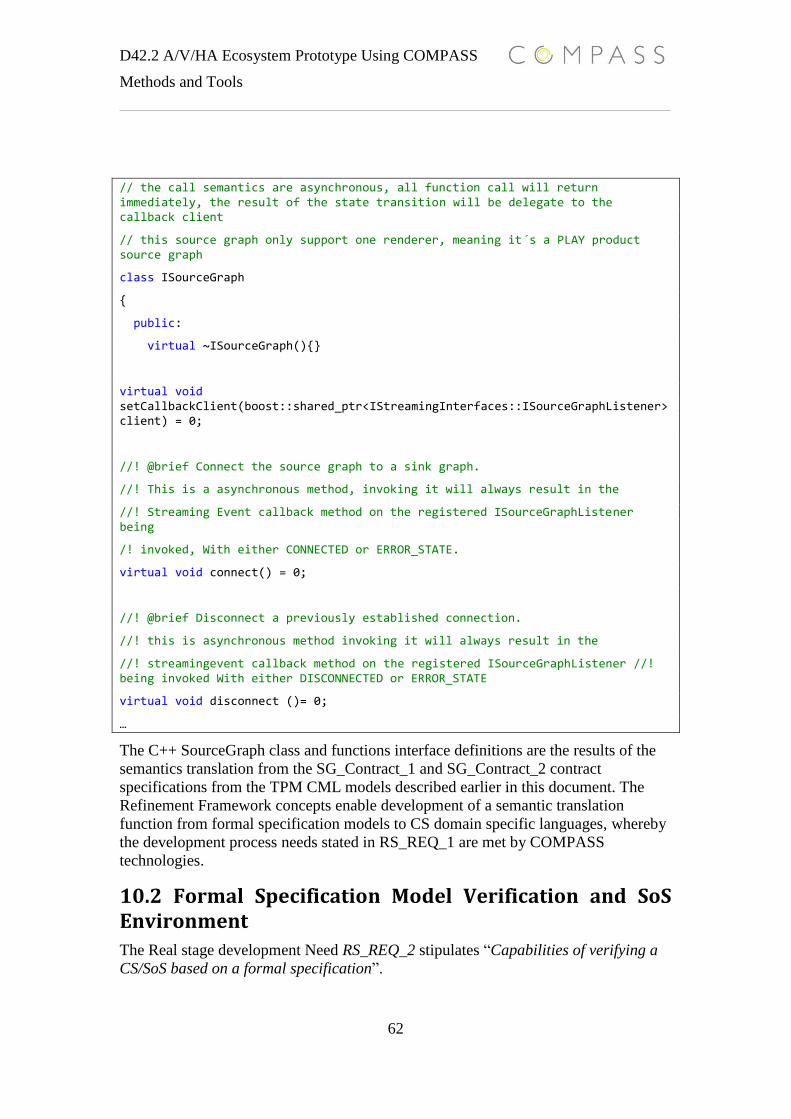
D42.2 A/V/HA Ecosystem Prototype Using COMPASS
Methods and Tools
62
// the call semantics are asynchronous, all function call will return immediately, the result of the state transition will be delegate to the callback client
// this source graph only support one renderer, meaning it´s a PLAY product source graph
class ISourceGraph
{
public:
virtual ~ISourceGraph(){}
virtual void setCallbackClient(boost::shared_ptr<IStreamingInterfaces::ISourceGraphListener> client) = 0;
//! @brief Connect the source graph to a sink graph.
//! This is a asynchronous method, invoking it will always result in the
//! Streaming Event callback method on the registered ISourceGraphListener being
/! invoked, With either CONNECTED or ERROR_STATE.
virtual void connect() = 0;
//! @brief Disconnect a previously established connection.
//! this is asynchronous method invoking it will always result in the
//! streamingevent callback method on the registered ISourceGraphListener //! being invoked With either DISCONNECTED or ERROR_STATE
virtual void disconnect ()= 0;
…
The C++ SourceGraph class and functions interface definitions are the results of the
semantics translation from the SG_Contract_1 and SG_Contract_2 contract
specifications from the TPM CML models described earlier in this document. The
Refinement Framework concepts enable development of a semantic translation
function from formal specification models to CS domain specific languages, whereby
the development process needs stated in RS_REQ_1 are met by COMPASS
technologies.
10.2 Formal Specification Model Verification and SoS Environment
The Real stage development Need RS_REQ_2 stipulates “Capabilities of verifying a
CS/SoS based on a formal specification”.

D42.2 A/V/HA Ecosystem Prototype Using COMPASS
Methods and Tools
63
The specification model holds the truth, so all traces of the CS implementation must
be the same as the traces from the specification models. The COMPASS technology
must provide an operational solution for verifying that for all t of the CML ADSM
model transitions system, there is a t` of the CS’s transition system where t`= t is true
(trace equivalence = ∀𝑡: 𝑇, ∃𝑡`: 𝑇` ∙ (𝑡 = 𝑡`)). The trace sets of ADSM can be timed
traces, meaning 𝑇𝑇(𝐴𝐷𝑆𝑀) ⊑ 𝑇𝑇(𝐶𝑆) must hold too.
The development process ontology relationships driving this need are the combination
of the Formal Stage relations stating: “Architectural Design Specification Test Models
can be created from elements (traces, proofs, contracts …) of a proven Architectural
Design Specification Model” and the Real state relation stating: “Product(s) are
verified by Architectural Design Specification Test Model(s)”. This implies that the
COMPASS technology must support construction of Architectural Design
Specification Test Models from the traces of an Architectural Design Specification
Model.
The interpreter of the COMPASS Symphony tool provides the feature of generating
CML traces from CML models. The approach for demonstrating trace equivalence
needs is simple and can be formulated as: since the specification holds the truth, we
can ask the model anything (event inputs, operations calls, etc). The specification
model’s answer will always be the right answer (trace outputs). The output traces are
translated into CML CS/SoS Test Case models. The Test Case models must then be
formally refined by the real CS’s software-and hardware systems. Below there is a
SourceGraph CS CML Test Case model, generated from the SourceGraph TPM CML
model’s traces.
process TestTraces2 =
begin
actions
act_connect = ch_genericEvent.(<CONNECT>)->ch_streamingReply.<CONNECTED>->act_error_connect
act_error_connect = ch_genericEvent.(<CONNECT>)->ch_streamingLayerError.<STATE_ERROR>->act_setstream -- deadlock if we dont get an error
act_setstream = ch_genericEvent.(<SETUPSTREAM>)->ch_streamingReply.(<STREAM_READY>)->act_play
act_play = ch_genericEvent.(<PLAY>)->ch_streamingReply.(<PLAYING>)->act_stop
act_stop = ch_genericEvent.(<STOP>)->ch_streamingReply.(<STOPPED>)->act_disconnect
act_disconnect = ch_genericEvent.(<DISCONNECT>)->ch_streamingReply.(<DISCONNECTED>)->ch_init->Skip
@ ch_init->act_connect
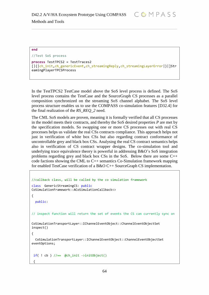
D42.2 A/V/HA Ecosystem Prototype Using COMPASS
Methods and Tools
64
end
//Test SoS process
process TestTPCS2 = TestTraces2 [|{|ch_init,ch_genericEvent,ch_streamingReply,ch_streamingLayerError|}|]StreamingPlayerTPCSProcess
In the TestTPCS2 TestCase model above the SoS level process is defined. The SoS
level process contains the TestCase and the SourceGraph CS processes as a parallel
composition synchronized on the streaming SoS channel alphabet. The SoS level
process structure enables us to use the COMPASS co-simulation features [D32.4] for
the final realization of the RS_REQ_2 need.
The CML SoS models are proven, meaning it is formally verified that all CS processes
in the model meets their contracts, and thereby the SoS desired properties P are met by
the specification models. So swapping one or more CS processes out with real CS
processes helps us validate the real CSs contracts compliance. This approach helps not
just in verification of white box CSs but also regarding contract conformance of
uncontrollable grey and black box CSs. Analysing the real CS contract semantics helps
also in verification of CS contract wrapper designs. The co-simulation tool and
underlying trace equivalence theory is powerful in addressing B&O’s SoS integration
problems regarding grey and black box CSs in the SoS. Below there are some C++
code factions showing the CML to C++ semantics Co-Simulation framework mapping
for enabled TestCase verification of a B&O C++ SourceGraph CS implementation.
//callback class, will be called by the co simulation framework
class GenericStreamingCS: public CoSimulationFramework::ACoSimulationCallback<>
{
public:
// inspect function will return the set of events the CS can currently sync on
CoSimulationTransportLayer::IChannelEventObject::ChannelEventObjectSet inspect()
{
CoSimulationTransportLayer::IChannelEventObject::ChannelEventObjectSet eventOptions;
if( ! cb ) //== @ch_init ->initObject()
{

D42.2 A/V/HA Ecosystem Prototype Using COMPASS
Methods and Tools
65
eventOptions.push_back(createSyncEventObject("ch_init"));
return eventOptions;
}
if( replyState)
{
// ch_streamingReply!(currentState) offer a reply event on the ch_streamingReply channel
// or ch_streamingLayerError if return value is ERROR_STATE
eventOptions.push_back(createWriteSyncOnEventObject<std::string>(channelName,CoSimulationFramework::ChannelOperation::SYNC_ON, ConvertStreamingEnumToString(cb->getResult())));
}
realStreamingState(eventOptions); …
In the CML TestTPCS2 SoS level process definition, the StreamingPlayerTPCSProcess
is replaced with a real CS C++ implementation in a Co-Simulation configuration. When
executing the SoS process from the Symphony tool, the real CS must offer the same
events to the environment as the CML process for enabled process synchronization
between the CS processes in the SoS. If the tool is not able to synchronize on the same
events, the tool will deadlock the simulation and we can denote the real CS as the sinner.
A successful Co-Simulation execution termination proves that the real CS is trace-
equivalent to the CML specification model, meaning the real CS is not a sinner, since
he tells the same trace truth as the proven formal model does when asked the same event
question.
The capabilities of verification of trace equivalence between proven models and real
CSs leads to the conclusion that the RS_REQ_2 development process needs are met by
the COMPASS technology. In D32.4, the reader can find more details about B&O’s
uses of the COMPASS Co-simulation framework and the semantics mapping between
the C++ Co-Simulation framework and the CSP communication semantics of CML.
To revisit the testing needs defined at the beginning of the case study application
section, the testing stage needs states:
SoS Testing Stage Requirements
o TS_REQ_1: Capabilities of identifying needed SoS test cases for
different AV product configurations
o TS_REG_2: Capabilities of testing SoS properties in different AV
product configurations
Throughout the COMPASS base MBSoSE development process, B&O has applied
COMPASS testing methods and tools like the Test Pattern, RT-Tester and Co-
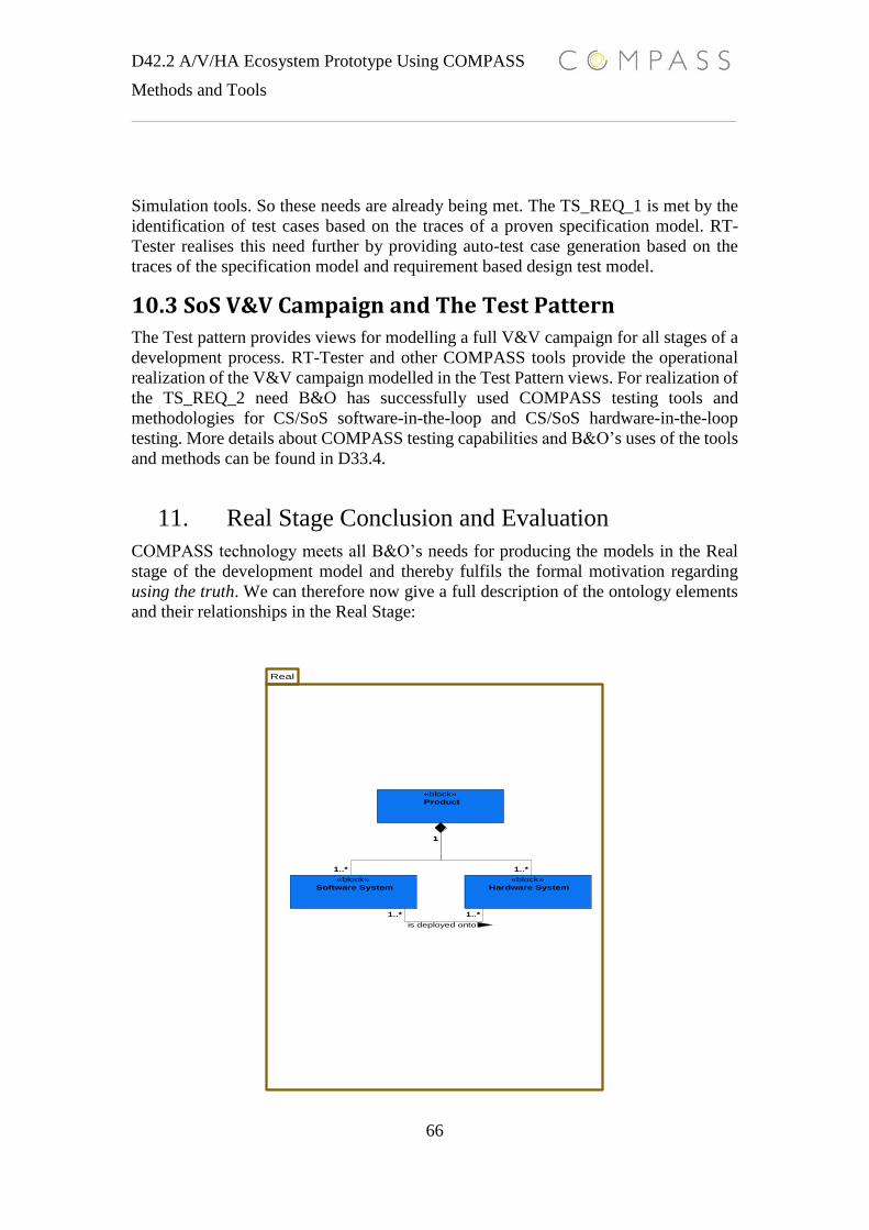
D42.2 A/V/HA Ecosystem Prototype Using COMPASS
Methods and Tools
66
Simulation tools. So these needs are already being met. The TS_REQ_1 is met by the
identification of test cases based on the traces of a proven specification model. RT-
Tester realises this need further by providing auto-test case generation based on the
traces of the specification model and requirement based design test model.
10.3 SoS V&V Campaign and The Test Pattern
The Test pattern provides views for modelling a full V&V campaign for all stages of a
development process. RT-Tester and other COMPASS tools provide the operational
realization of the V&V campaign modelled in the Test Pattern views. For realization of
the TS_REQ_2 need B&O has successfully used COMPASS testing tools and
methodologies for CS/SoS software-in-the-loop and CS/SoS hardware-in-the-loop
testing. More details about COMPASS testing capabilities and B&O’s uses of the tools
and methods can be found in D33.4.
11. Real Stage Conclusion and Evaluation
COMPASS technology meets all B&O’s needs for producing the models in the Real
stage of the development model and thereby fulfils the formal motivation regarding
using the truth. We can therefore now give a full description of the ontology elements
and their relationships in the Real Stage:
1..*
1
1..*
1
1..*1..*
Real
«block»
Product
«block»
Software System
«block»
Hardware System
«block»
Product
«block»
Software System
«block»
Hardware System
1..*
1
1..*
1
1..*1..*
is deployed onto
D42.2 A/V/HA Ecosystem Prototype Using COMPASS
Methods and Tools
67
The Real stage contains the B&O Product, which is a specialization of the
COMPASS ontology concept System
A Product consists of Software System(s) and Hardware System(s)
Software Systems(s) are deployed onto Hardware System(s)
A Product can be generated from contract specifications of an Architectural
Design Specification Model
A Product can be analysed by the traces from Architectural Design
Specification Model
A product has been verified by the Architectural Design Specification Test
Model
Architectural Design Specification Test Model can be created from the traces
of an Architectural Design Specification Model
Using the TRL validation process, the following scores are given for COMPASS
technologies’ realization of the Real stage’s development process needs. The TRLs are
combined into one table. The table contains the TRLs for the COMPASS
methodologies used in the real stage, and for the tools realization of the methodologies.

68
Work Product Source
info
Need
defined
Validation
defined
Approach
Test
application
Case
study
Tailored
model
Applied
approach
TRL
Symphony Test
Automation
Plug-in
DoW
D42.1
D34.1
DoW
D42.2
D34.1
D34.1 D34.1 D42.2 7
Symphony
Co-simulation
Engine
DoW D32.4 D32.4
D42.2
Dow
D32.4 D32.4 D42.2 6
Symphony´s
Linkage to
Executable
Software
DoW D32.3 D32.3
D42.2
DoW
D32.3 D32.3 D42.2 6
Specialised Test
Strategies
DoW D34.2 D34.2
DoW
D34.2 D34.2 D42.2 7
Contract
Pattern
DoW,
D22.1
D22.3
D22.6
D22.3
D22.6
D22.3 D22.3 D42.2 7
69
Some comments regarding the TRLs in the table above:
The overall TRL score for the Real stage are between 6 and 7. Once again, it is the
tool’s maturity and lack of proper industrial target documentation that is preventing
higher TRL scores. The COMPASS technologies applied to the Real stage of the
development process are generally more mature and therefore more deployable than
some of the other tools.
The Real stage was the last stage of the COMPASS technology based development
process. The following section will conclude the overall achievements and further
work.
12. Conclusion
This report has described an industrial model-based SoS/CS development process. The
process starts from needs to SoS/CS product deployment, with parallel testing, and
validation and verification activities for the different development stages of the process.
For each stage of the MBSoSE development process a set of COMPASS technologies
has been applied. The results of applying COMPASS technology have been validated
against the development process needs. The needs for a given stage of the process were
derived from B&O’s SoS problem domain and organisational development structure.
The conclusion regarding COMPASS usefulness versus the SoS development process
needs is:
COMPASS model-based methodologies and tools have met B&O’s needs for
improving their development processes regarding SoS/CS engineering. Arguments can
be raised against the industry maturity regarding some of the formal tools, but the
theoretical foundations are proven applicable for industry. The motivation for using the
formal aspects of COMPASS technology in an industrial context has been proved to be
possible and realizable by COMPASS. The semi-formal COMPASS technologies have
already been adopted by B&O, although adoption fo the formal technologies is
currently hindered by tool maturity and the requirement levels for formal knowledge.
The justification for using the formal tools and formal argument is proven by the
specification model results. The verification results described in this document and
other COMPASS documents could not have been achieved using non-formal methods
and tools.
Regarding the development of the CML language, the following argument could be
raised: does the world really need a new formal language? CML is a powerful formal
language combining the needed semantics for handling the complexity of modelling
SoS domains. This document has shown CML’s feasibly for modelling B&O’s SoS
contractual needs. The B&O case study CML model produced led us to conclude that
CML has the required expressive strength and semantics for SoS modelling.
One of the unique selling points for COMPASS is the linking of
refinements/methods/concepts between the stages of the development process. The
capabilities of preserving and using achieved goals from and between stages are highly
desirable for industry. An example of this is the capability for using the results from
the formal stage to validate the real stage implementations. Another selling point of
COMPASS is the ontology methodology. Correct use of the ontology methodology can
enable consistent communication and reasoning about complex SoS domains. The
development of SoS-level domain-specific semantics is heavily needed in industry for
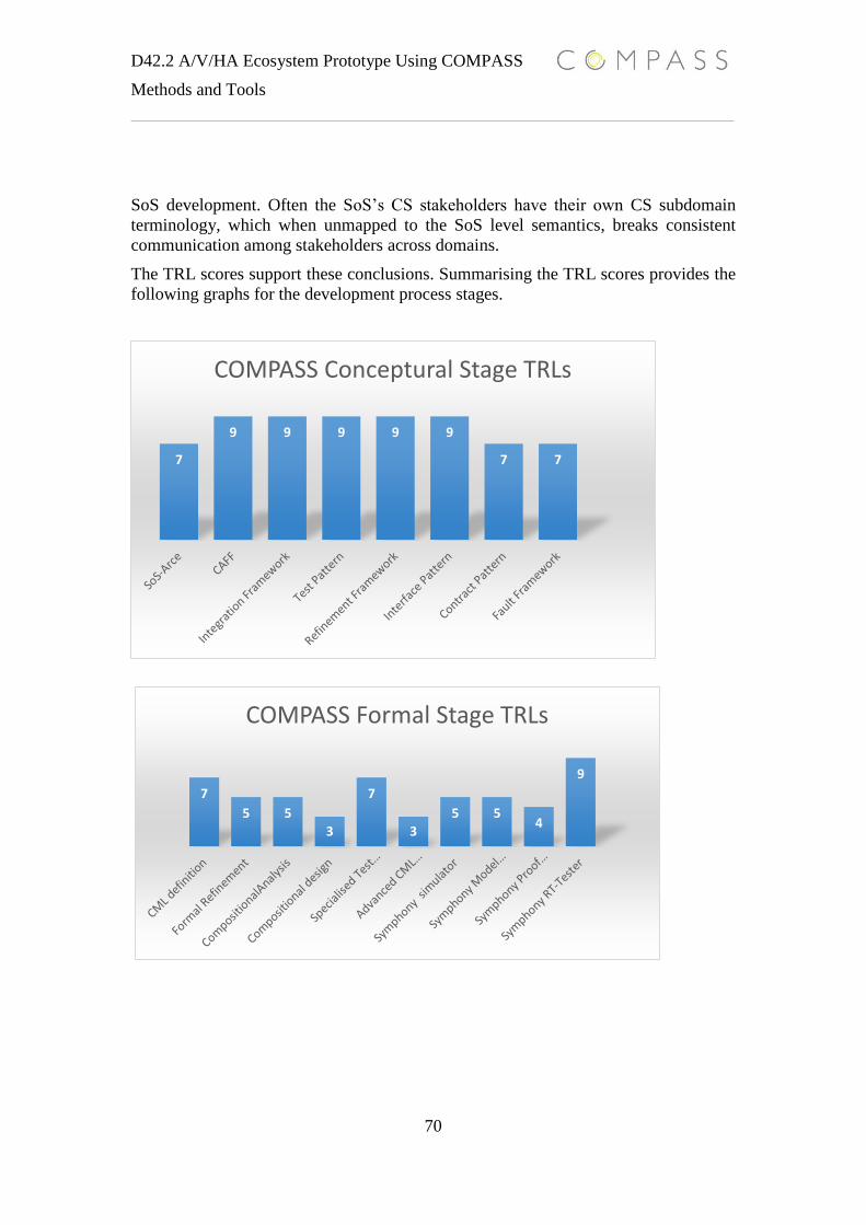
D42.2 A/V/HA Ecosystem Prototype Using COMPASS
Methods and Tools
70
SoS development. Often the SoS’s CS stakeholders have their own CS subdomain
terminology, which when unmapped to the SoS level semantics, breaks consistent
communication among stakeholders across domains.
The TRL scores support these conclusions. Summarising the TRL scores provides the
following graphs for the development process stages.
7
5 5
3
7
3
5 54
9
COMPASS Formal Stage TRLs
7
9 9 9 9 9
7 7
COMPASS Conceptural Stage TRLs

D42.2 A/V/HA Ecosystem Prototype Using COMPASS
Methods and Tools
71
The TRLs tables can be interpreted from two angles: a research angle and an industry
angle. The research acceptance criterion is TRL levels 4 to 6, where the acceptance
criterion TRL level for industry is from 6 to 9. The COMPASS technologies applied to
B&O’s case study score a TRL average of 6.4. A TRL average of 6.4 supports the
argument that COMPASS’s theoretical foundations have proven applicable for
industry, but are not yet deployable. However, there are hopes for the future industrial
deployment of COMPASS.
7
6 6
7 7
Symphony TestAutomation
Symphony Co-simulation
Symphony´sLinkage toExecutable
Specialised TestStrategies
Contract Pattern
COMPASS Real Stage TRLs

D42.2 A/V/HA Ecosystem Prototype Using COMPASS
Methods and Tools
72
13. References
[COMPASS D21.1] COMPASS. Report on Guidelines for SoS Requirements. Document
Number: D21.1. Technical report: http://www.compass-research.eu,
2012.
[COMPASS D21.4] COMPASS. Report on Guidelines for System Integration for SoS.
Document Number: D21.4. Technical report: http://www.compass-
research.eu, 2013.
[COMPASS D21.2] COMPASS. Initial Report on Guidelines for Architectural Level SoS
Modelling. Document Number: D21.2. Technical report:
http://www.compass-research.eu, 2013.
[COMPASS D22.3] COMPASS. Report on Modelling Patterns for SoS Architectures.
Document Number: D22.3. Technical report: http://www.compass-
research.eu, 2014.
[COMPASS D22.5] COMPASS. Report on Refinement Strategies for SoS Models.
Document Number: D22.5. Technical report: http://www.compass-
research.eu, 2013.
[COMPASS D32.2] COMPASS. Final Simulator for CML.
Document Number: D32.2. Technical report: http://www.compass-
research.eu, 2014.
[COMPASS D32.4] COMPASS. Co-simulation Engine.
Document Number: D32.4. Technical report: http://www.compass-
research.eu, 2014.
[COMPASS D33.1] COMPASS. Model-Checking Support.
Document Number: D33.1. Technical report: http://www.compass-
research.eu, 2014.
[COMPASS D33.2] COMPASS. Theorem Proving Support.
Document Number: D33.2. Technical report: http://www.compass-
research.eu, 2014.
[COMPASS D34.1] COMPASS. Test Automation Support.
D42.2 A/V/HA Ecosystem Prototype Using COMPASS
Methods and Tools
73
Document Number: D34.1. Technical report: http://www.compass-
research.eu, 2014.
[COMPASS D34.2] COMPASS. Specialised Test Strategies.
Document Number: D34.2. Technical report: http://www.compass-
research.eu, 2014.
[COMPASS D22.4] COMPASS. Final report on combing SysML and CML. Document
Number: D22.4. Technical report: http://www.compass-research.eu,
2014.
[COMPASS D23.5] COMPASS. CML definition 4. Document Number D23.5. Technical
report: http://www.compass-research.eu, 2014.
[COMPASS D24.2] COMPASS. Report on Timed Fault Tree Analysis. Document
Number: D24.2. Technical report: http://www.compass-research.eu,
2013.
[COMPASS D41.4] COMPASS. Accident Response Case Study Engineering Analysis
Report Using Current Methods & Tools. Document Number: D41.1.
Technical report: http://www.compass-research.eu, 2013.
[COMPASS D43.2] COMPASS. Challenge Problem Analysis Using Current Methods &
Tools. Document Number: D43.2. Technical report:
http://www.compass-research.eu, 2013.
[DoD08] Systems and Software Engineering. Systems Engineering Guide for
Systems of Systems. Tech. Rep. Version 1.0., Office of the Deputy
Under Secretary of Defense for Acquisition and Technology,
Department of Defense. August 2008.
[E-FRAME D13, 2007] E-FRAME. ‘D13 – Consolidated User Needs for Cooperative
Systems’. E-FRAME Project; 2007
[Fitzgerald&08] J.S. Fitzgerald, P.G. Larsen, P. Mukherjee, N. Plat and M.
Verhoef, Validated Designs for Object-oriented Systems, Springer,
2005, ISBN 1-85233-881-4.
[Fitzgerald&13] John Fitzgerald, Simon Foster, Claire Ingram, Peter Gorm Larsen and
Jim Woodcock, Model-based Engineering for Systems of Systems: the
COMPASS Manifesto, October 2013.
D42.2 A/V/HA Ecosystem Prototype Using COMPASS
Methods and Tools
74
[Fitzgerald&14] Fitzgerald J, Larsen PG, Woodcock J. Foundations for Model-Based
Engineering of Systems of Systems. In: Fourth International
Conference on Complex Systems Design & Management (CSD&M)
2013. 2014, Paris, France: Springer
[Nielsen et al 2013] Nielsen, C. B., Larsen, P. G., Fitzgerald, J., Woodcock, J. and
Peleska, J. ‘Model-based Engineering of Systems of Systems’.
COMPASS technical report, 2013. Available from:
http://www.compass-research.eu/resources/sos.pdf
[HLK2014] Stefan Hallerstede, Klaus Kristensen, Peter Gorm Larsen.
Modelling Of Systems Of Systems - An Event-B Perspective Of a
VDM Project. Rodin User and Developer Workshop, 2014.
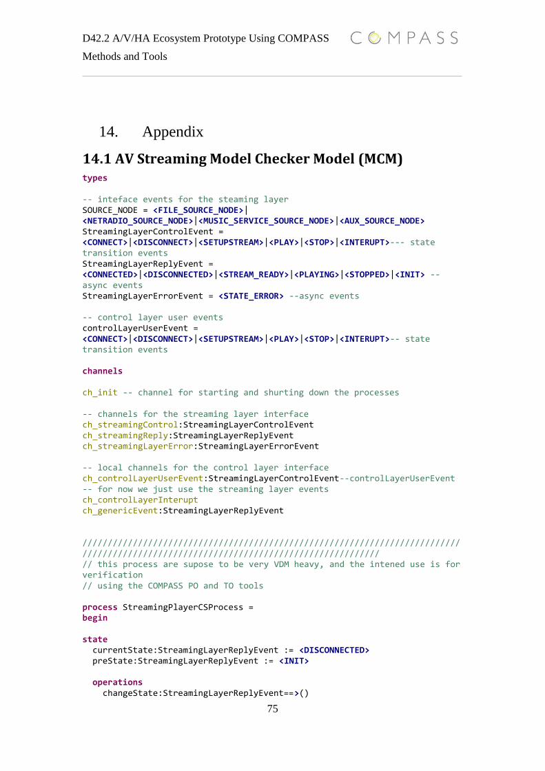
D42.2 A/V/HA Ecosystem Prototype Using COMPASS
Methods and Tools
75
14. Appendix
14.1 AV Streaming Model Checker Model (MCM) types -- inteface events for the steaming layer SOURCE_NODE = <FILE_SOURCE_NODE>| <NETRADIO_SOURCE_NODE>|<MUSIC_SERVICE_SOURCE_NODE>|<AUX_SOURCE_NODE> StreamingLayerControlEvent = <CONNECT>|<DISCONNECT>|<SETUPSTREAM>|<PLAY>|<STOP>|<INTERUPT>--- state transition events StreamingLayerReplyEvent = <CONNECTED>|<DISCONNECTED>|<STREAM_READY>|<PLAYING>|<STOPPED>|<INIT> --async events StreamingLayerErrorEvent = <STATE_ERROR> --async events -- control layer user events controlLayerUserEvent = <CONNECT>|<DISCONNECT>|<SETUPSTREAM>|<PLAY>|<STOP>|<INTERUPT>-- state transition events channels ch_init -- channel for starting and shurting down the processes -- channels for the streaming layer interface ch_streamingControl:StreamingLayerControlEvent ch_streamingReply:StreamingLayerReplyEvent ch_streamingLayerError:StreamingLayerErrorEvent -- local channels for the control layer interface ch_controlLayerUserEvent:StreamingLayerControlEvent--controlLayerUserEvent -- for now we just use the streaming layer events ch_controlLayerInterupt ch_genericEvent:StreamingLayerReplyEvent ////////////////////////////////////////////////////////////////////////////////////////////////////////////////////////////////////// // this process are supose to be very VDM heavy, and the intened use is for verification // using the COMPASS PO and TO tools process StreamingPlayerCSProcess = begin state currentState:StreamingLayerReplyEvent := <DISCONNECTED> preState:StreamingLayerReplyEvent := <INIT> operations changeState:StreamingLayerReplyEvent==>()
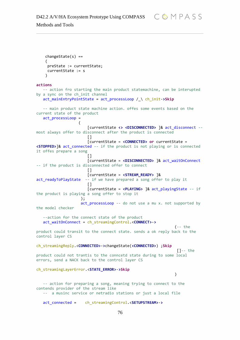
D42.2 A/V/HA Ecosystem Prototype Using COMPASS
Methods and Tools
76
changeState(s) == ( preState := currentState; currentState := s ) actions -- action fro starting the main product statemachine, can be interupted by a sync on the ch_init channel act_mainEntryPointState = act_processLoop /_\ ch_init->Skip -- main product state machine action. offes some events based on the current state of the product act_processLoop = ( [currentState <> <DISCONNECTED> ]& act_disconnect -- most always offer to disconnect after the product is connected [] [currentState = <CONNECTED> or currentState = <STOPPED>]& act_connected -- if the product is not playing or is connected it offes prepare a song [] [currentState = <DISCONNECTED> ]& act_waitOnConnect -- if the product is disconnected offer to connect [] [currentState = <STREAM_READY> ]& act_readyToPlayState -- if we have prepared a song offer to play it [] [currentState = <PLAYING> ]& act_playingState -- if the product is playing a song offer to stop it ); act_processLoop -- do not use a mu x. not supported by the model checker --action for the connect state of the product act_waitOnConnect = ch_streamingControl.<CONNECT>-> (-- the product could transit to the connect state. sends a ok reply back to the control layer CS ch_streamingReply.<CONNECTED>->changeState(<CONNECTED>) ;Skip []-- the product could not trantis to the conncetd state during to some local errors, send a NACK back to the control layer CS ch_streamingLayerError.<STATE_ERROR>->Skip ) -- action for preparing a song, meaning trying to connect to the contends provider of the stream like -- a musinc service or netradio stations or just a local file act_connected = ch_streamingControl.<SETUPSTREAM>->

D42.2 A/V/HA Ecosystem Prototype Using COMPASS
Methods and Tools
77
( -- the product can play the stream. sends a OK back to the control layer CS and change state to ready to play ch_streamingReply.<STREAM_READY>->(changeState(<STREAM_READY>);Skip) []-- could not connect to the provider or cannot decode the stream. send a NACK back to the control layer CS ch_streamingLayerError.<STATE_ERROR>->(changeState(<CONNECTED>));Skip //change the state back to connected, no stream are ready //even if we had a stream ready before ) act_readyToPlayState = ch_streamingControl.<PLAY>-> ( ch_streamingReply.<PLAYING>->changeState(<PLAYING>);Skip [] ch_streamingLayerError.<STATE_ERROR>->Skip ) [] act_connected act_playingState = ch_streamingControl.<STOP>-> ( ch_streamingReply.<STOPPED>->changeState(<CONNECTED>);Skip [] ch_streamingLayerError.<STATE_ERROR>->Skip ) act_disconnect = (ch_streamingControl.<DISCONNECT>->ch_streamingReply.<DISCONNECTED>->changeState(<DISCONNECTED>);Skip) @ch_init ->act_mainEntryPointState end ///////////////////////////////////////////////////////////////////////////////////////////////////////////////////////////////////////////////////////////////// //test sections // CML processes are model tranlations of the Req ARCE framework vaidation view points // Sunshine process, testing a CS sourcegraph refineement process TestTraces1 = -- test the sunshine seq of the interface impl. begin actions
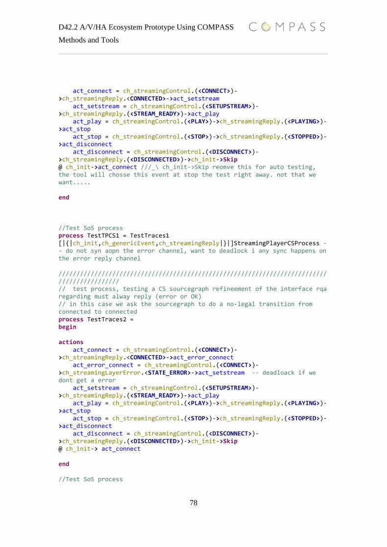
D42.2 A/V/HA Ecosystem Prototype Using COMPASS
Methods and Tools
78
act_connect = ch_streamingControl.(<CONNECT>)->ch_streamingReply.<CONNECTED>->act_setstream act_setstream = ch_streamingControl.(<SETUPSTREAM>)->ch_streamingReply.(<STREAM_READY>)->act_play act_play = ch_streamingControl.(<PLAY>)->ch_streamingReply.(<PLAYING>)->act_stop act_stop = ch_streamingControl.(<STOP>)->ch_streamingReply.(<STOPPED>)->act_disconnect act_disconnect = ch_streamingControl.(<DISCONNECT>)->ch_streamingReply.(<DISCONNECTED>)->ch_init->Skip @ ch_init->act_connect ///_\ ch_init->Skip reomve this for auto testing, the tool will chosse this event at stop the test right away. not that we want..... end //Test SoS process process TestTPCS1 = TestTraces1 [|{|ch_init,ch_genericEvent,ch_streamingReply|}|]StreamingPlayerCSProcess -- do not syn aopn the error channel, want to deadlock i any sync happens on the error reply channel //////////////////////////////////////////////////////////////////////////////////////////// // test process, testing a CS sourcegraph refineement of the interface rqa regarding must alway reply (error or OK) // in this case we ask the sourcegraph to do a no-legal transition from connected to connected process TestTraces2 = begin actions act_connect = ch_streamingControl.(<CONNECT>)->ch_streamingReply.<CONNECTED>->act_error_connect act_error_connect = ch_streamingControl.(<CONNECT>)->ch_streamingLayerError.<STATE_ERROR>->act_setstream -- deadloack if we dont get a error act_setstream = ch_streamingControl.(<SETUPSTREAM>)->ch_streamingReply.(<STREAM_READY>)->act_play act_play = ch_streamingControl.(<PLAY>)->ch_streamingReply.(<PLAYING>)->act_stop act_stop = ch_streamingControl.(<STOP>)->ch_streamingReply.(<STOPPED>)->act_disconnect act_disconnect = ch_streamingControl.(<DISCONNECT>)->ch_streamingReply.(<DISCONNECTED>)->ch_init->Skip @ ch_init-> act_connect end //Test SoS process
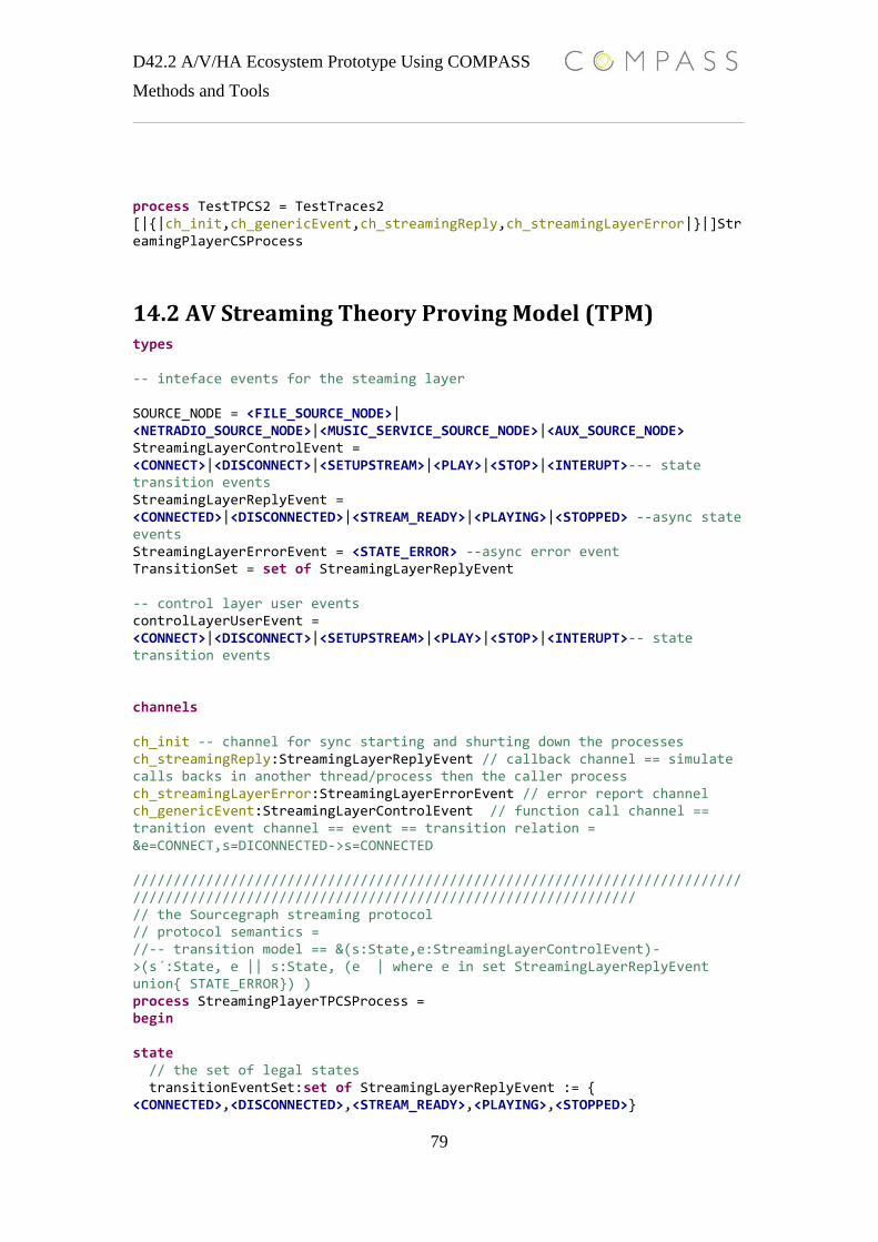
D42.2 A/V/HA Ecosystem Prototype Using COMPASS
Methods and Tools
79
process TestTPCS2 = TestTraces2 [|{|ch_init,ch_genericEvent,ch_streamingReply,ch_streamingLayerError|}|]StreamingPlayerCSProcess
14.2 AV Streaming Theory Proving Model (TPM) types -- inteface events for the steaming layer SOURCE_NODE = <FILE_SOURCE_NODE>| <NETRADIO_SOURCE_NODE>|<MUSIC_SERVICE_SOURCE_NODE>|<AUX_SOURCE_NODE> StreamingLayerControlEvent = <CONNECT>|<DISCONNECT>|<SETUPSTREAM>|<PLAY>|<STOP>|<INTERUPT>--- state transition events StreamingLayerReplyEvent = <CONNECTED>|<DISCONNECTED>|<STREAM_READY>|<PLAYING>|<STOPPED> --async state events StreamingLayerErrorEvent = <STATE_ERROR> --async error event TransitionSet = set of StreamingLayerReplyEvent -- control layer user events controlLayerUserEvent = <CONNECT>|<DISCONNECT>|<SETUPSTREAM>|<PLAY>|<STOP>|<INTERUPT>-- state transition events channels ch_init -- channel for sync starting and shurting down the processes ch_streamingReply:StreamingLayerReplyEvent // callback channel == simulate calls backs in another thread/process then the caller process ch_streamingLayerError:StreamingLayerErrorEvent // error report channel ch_genericEvent:StreamingLayerControlEvent // function call channel == tranition event channel == event == transition relation = &e=CONNECT,s=DICONNECTED->s=CONNECTED ///////////////////////////////////////////////////////////////////////////////////////////////////////////////////////////////////////// // the Sourcegraph streaming protocol // protocol semantics = //-- transition model == &(s:State,e:StreamingLayerControlEvent)->(s´:State, e || s:State, (e | where e in set StreamingLayerReplyEvent union{ STATE_ERROR}) ) process StreamingPlayerTPCSProcess = begin state // the set of legal states transitionEventSet:set of StreamingLayerReplyEvent := { <CONNECTED>,<DISCONNECTED>,<STREAM_READY>,<PLAYING>,<STOPPED>}
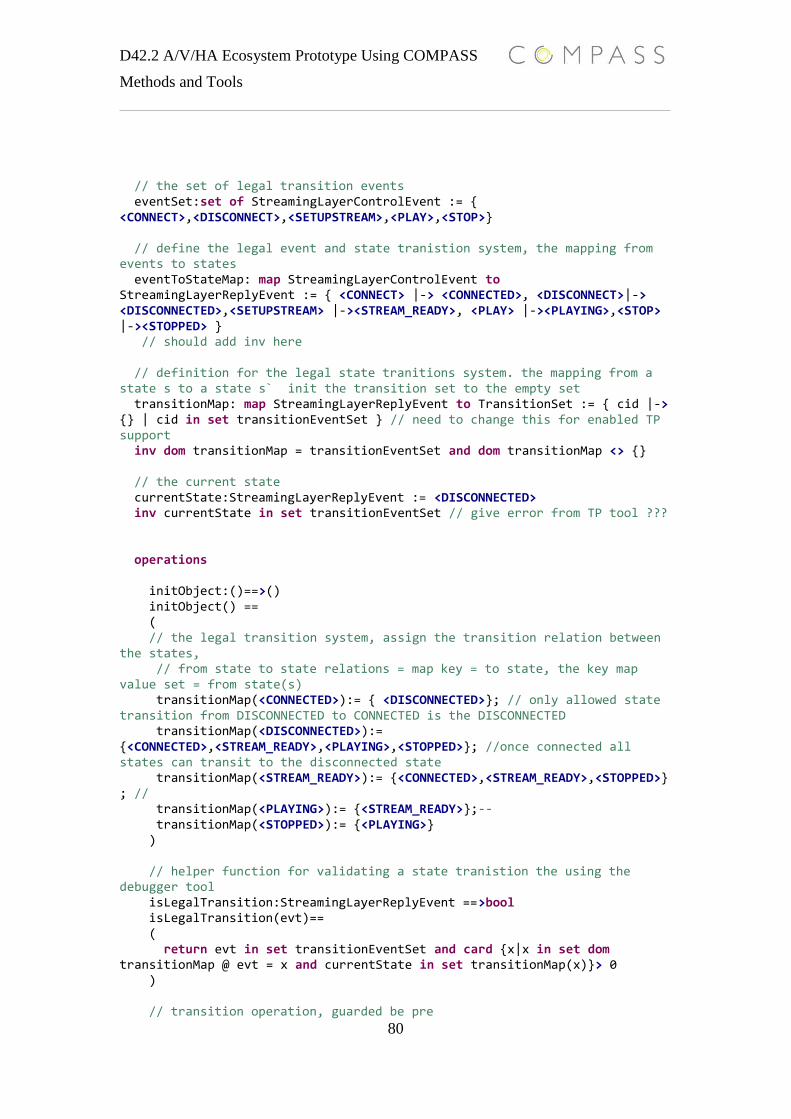
D42.2 A/V/HA Ecosystem Prototype Using COMPASS
Methods and Tools
80
// the set of legal transition events eventSet:set of StreamingLayerControlEvent := { <CONNECT>,<DISCONNECT>,<SETUPSTREAM>,<PLAY>,<STOP>} // define the legal event and state tranistion system, the mapping from events to states eventToStateMap: map StreamingLayerControlEvent to StreamingLayerReplyEvent := { <CONNECT> |-> <CONNECTED>, <DISCONNECT>|-> <DISCONNECTED>,<SETUPSTREAM> |-><STREAM_READY>, <PLAY> |-><PLAYING>,<STOP> |-><STOPPED> } // should add inv here // definition for the legal state tranitions system. the mapping from a state s to a state s` init the transition set to the empty set transitionMap: map StreamingLayerReplyEvent to TransitionSet := { cid |-> {} | cid in set transitionEventSet } // need to change this for enabled TP support inv dom transitionMap = transitionEventSet and dom transitionMap <> {} // the current state currentState:StreamingLayerReplyEvent := <DISCONNECTED> inv currentState in set transitionEventSet // give error from TP tool ??? operations initObject:()==>() initObject() == ( // the legal transition system, assign the transition relation between the states, // from state to state relations = map key = to state, the key map value set = from state(s) transitionMap(<CONNECTED>):= { <DISCONNECTED>}; // only allowed state transition from DISCONNECTED to CONNECTED is the DISCONNECTED transitionMap(<DISCONNECTED>):= {<CONNECTED>,<STREAM_READY>,<PLAYING>,<STOPPED>}; //once connected all states can transit to the disconnected state transitionMap(<STREAM_READY>):= {<CONNECTED>,<STREAM_READY>,<STOPPED>} ; // transitionMap(<PLAYING>):= {<STREAM_READY>};-- transitionMap(<STOPPED>):= {<PLAYING>} ) // helper function for validating a state tranistion the using the debugger tool isLegalTransition:StreamingLayerReplyEvent ==>bool isLegalTransition(evt)== ( return evt in set transitionEventSet and card {x|x in set dom transitionMap @ evt = x and currentState in set transitionMap(x)}> 0 ) // transition operation, guarded be pre
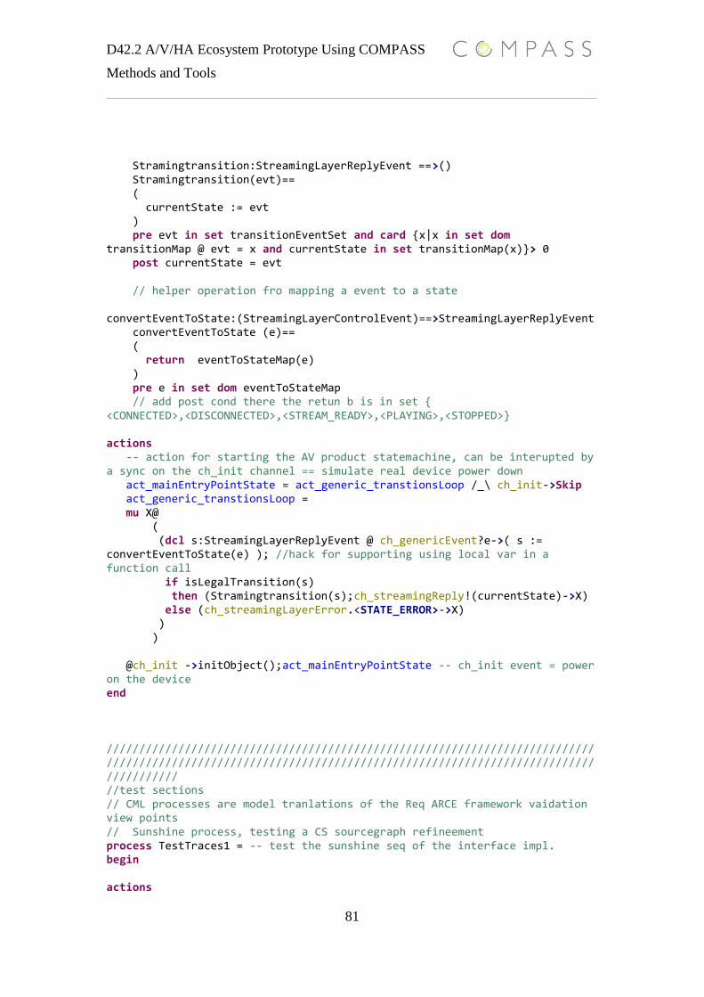
D42.2 A/V/HA Ecosystem Prototype Using COMPASS
Methods and Tools
81
Stramingtransition:StreamingLayerReplyEvent ==>() Stramingtransition(evt)== ( currentState := evt ) pre evt in set transitionEventSet and card {x|x in set dom transitionMap @ evt = x and currentState in set transitionMap(x)}> 0 post currentState = evt // helper operation fro mapping a event to a state convertEventToState:(StreamingLayerControlEvent)==>StreamingLayerReplyEvent convertEventToState (e)== ( return eventToStateMap(e) ) pre e in set dom eventToStateMap // add post cond there the retun b is in set { <CONNECTED>,<DISCONNECTED>,<STREAM_READY>,<PLAYING>,<STOPPED>} actions -- action for starting the AV product statemachine, can be interupted by a sync on the ch_init channel == simulate real device power down act_mainEntryPointState = act_generic_transtionsLoop /_\ ch_init->Skip act_generic_transtionsLoop = mu X@ ( (dcl s:StreamingLayerReplyEvent @ ch_genericEvent?e->( s := convertEventToState(e) ); //hack for supporting using local var in a function call if isLegalTransition(s) then (Stramingtransition(s);ch_streamingReply!(currentState)->X) else (ch_streamingLayerError.<STATE_ERROR>->X) ) ) @ch_init ->initObject();act_mainEntryPointState -- ch_init event = power on the device end ///////////////////////////////////////////////////////////////////////////////////////////////////////////////////////////////////////////////////////////////// //test sections // CML processes are model tranlations of the Req ARCE framework vaidation view points // Sunshine process, testing a CS sourcegraph refineement process TestTraces1 = -- test the sunshine seq of the interface impl. begin actions

D42.2 A/V/HA Ecosystem Prototype Using COMPASS
Methods and Tools
82
act_connect = ch_genericEvent.(<CONNECT>)->ch_streamingReply.<CONNECTED>->act_setstream act_setstream = ch_genericEvent.(<SETUPSTREAM>)->ch_streamingReply.(<STREAM_READY>)->act_play act_play = ch_genericEvent.(<PLAY>)->ch_streamingReply.(<PLAYING>)->act_stop act_stop = ch_genericEvent.(<STOP>)->ch_streamingReply.(<STOPPED>)->act_disconnect act_disconnect = ch_genericEvent.(<DISCONNECT>)->ch_streamingReply.(<DISCONNECTED>)->ch_init->Skip @ ch_init->act_connect ///_\ch_init->Skip reomve this for auto testing, the tool will chosse this event at stop the test right away. not that we want..... end //Test SoS process process TestTPCS1 = TestTraces1 [|{|ch_init,ch_genericEvent,ch_streamingReply|}|]StreamingPlayerTPCSProcess -- do not syn aopn the error channel, want to deadlock i any sync happens on the error reply channel //////////////////////////////////////////////////////////////////////////////////////////// // test process, testing a CS sourcegraph refineement of the interface rqa regarding must alway reply (error or OK) // in this case we ask the sourcegraph to do a no-legal transition from connected to connected process TestTraces2 = begin actions act_connect = ch_genericEvent.(<CONNECT>)->ch_streamingReply.<CONNECTED>->act_error_connect act_error_connect = ch_genericEvent.(<CONNECT>)->ch_streamingLayerError.<STATE_ERROR>->act_setstream -- deadloack if we dont get a error act_setstream = ch_genericEvent.(<SETUPSTREAM>)->ch_streamingReply.(<STREAM_READY>)->act_play act_play = ch_genericEvent.(<PLAY>)->ch_streamingReply.(<PLAYING>)->act_stop act_stop = ch_genericEvent.(<STOP>)->ch_streamingReply.(<STOPPED>)->act_disconnect act_disconnect = ch_genericEvent.(<DISCONNECT>)->ch_streamingReply.(<DISCONNECTED>)->ch_init->Skip @ ch_init->act_connect end //Test SoS process process TestTPCS2 = TestTraces2 [|{|ch_init,ch_genericEvent,ch_streamingReply,ch_streamingLayerError|}|]StreamingPlayerTPCSProcess

D42.2 A/V/HA Ecosystem Prototype Using COMPASS
Methods and Tools
83
////////////////////////////////////////////////////////////////////////////////////////////////////// //section for auto test cases process StreamingPlayerTPCSProcessTest_10 = begin actions testTrace = ch_init->ch_genericEvent.(<CONNECT>)->ch_streamingReply.(<CONNECTED>)->ch_genericEvent.(<PLAY>)->ch_streamingLayerError.(<STATE_ERROR>)->ch_genericEvent.(<SETUPSTREAM>)->ch_streamingReply.(<STREAM_READY>)->ch_genericEvent.(<STOP>)->ch_streamingLayerError.(<STATE_ERROR>)->ch_genericEvent.(<PLAY>)->ch_streamingReply.(<PLAYING>)->ch_genericEvent.(<DISCONNECT>)->ch_streamingReply.(<DISCONNECTED>)->ch_init->Skip @ testTrace end process StreamingPlayerTPCSProcessTest_10_Main = StreamingPlayerTPCSProcessTest_10 [|{|ch_init,ch_genericEvent,ch_streamingReply,ch_streamingLayerError|}|] StreamingPlayerTPCSProcess process StreamingPlayerTPCSProcessTest_68 = begin actions testTrace = ch_init->ch_genericEvent.(<DISCONNECT>)->ch_streamingLayerError.(<STATE_ERROR>)->ch_genericEvent.(<CONNECT>)->ch_streamingReply.(<CONNECTED>)->ch_genericEvent.(<SETUPSTREAM>)->ch_streamingReply.(<STREAM_READY>)->ch_genericEvent.(<SETUPSTREAM>)->ch_streamingReply.(<STREAM_READY>)->ch_genericEvent.(<PLAY>)->ch_streamingReply.(<PLAYING>)->ch_genericEvent.(<PLAY>)->ch_streamingLayerError.(<STATE_ERROR>)->ch_genericEvent.(<STOP>)->ch_streamingReply.(<STOPPED>)->ch_init->Skip @ testTrace end process StreamingPlayerTPCSProcessTest_68_Main = StreamingPlayerTPCSProcessTest_68 [|{|ch_init,ch_genericEvent,ch_streamingLayerError,ch_streamingReply|}|] StreamingPlayerTPCSProcess ///////////////////////////////////////////////// process StreamingPlayerTPCSProcessTest_96 = begin actions
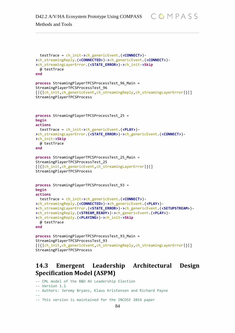
D42.2 A/V/HA Ecosystem Prototype Using COMPASS
Methods and Tools
84
testTrace = ch_init->ch_genericEvent.(<CONNECT>)->ch_streamingReply.(<CONNECTED>)->ch_genericEvent.(<CONNECT>)->ch_streamingLayerError.(<STATE_ERROR>)->ch_init->Skip @ testTrace end process StreamingPlayerTPCSProcessTest_96_Main = StreamingPlayerTPCSProcessTest_96 [|{|ch_init,ch_genericEvent,ch_streamingReply,ch_streamingLayerError|}|] StreamingPlayerTPCSProcess process StreamingPlayerTPCSProcessTest_25 = begin actions testTrace = ch_init->ch_genericEvent.(<PLAY>)->ch_streamingLayerError.(<STATE_ERROR>)->ch_genericEvent.(<CONNECT>)->ch_init->Skip @ testTrace end process StreamingPlayerTPCSProcessTest_25_Main = StreamingPlayerTPCSProcessTest_25 [|{|ch_init,ch_genericEvent,ch_streamingLayerError|}|] StreamingPlayerTPCSProcess process StreamingPlayerTPCSProcessTest_93 = begin actions testTrace = ch_init->ch_genericEvent.(<CONNECT>)->ch_streamingReply.(<CONNECTED>)->ch_genericEvent.(<PLAY>)->ch_streamingLayerError.(<STATE_ERROR>)->ch_genericEvent.(<SETUPSTREAM>)->ch_streamingReply.(<STREAM_READY>)->ch_genericEvent.(<PLAY>)->ch_streamingReply.(<PLAYING>)->ch_init->Skip @ testTrace end process StreamingPlayerTPCSProcessTest_93_Main = StreamingPlayerTPCSProcessTest_93 [|{|ch_init,ch_genericEvent,ch_streamingReply,ch_streamingLayerError|}|] StreamingPlayerTPCSProcess
14.3 Emergent Leadership Architectural Design Specification Model (ASPM) -- CML model of the B&O AV Leadership Election -- Version 1.1 -- Authors: Jeremy Bryans, Klaus Kristensen and Richard Payne -- -- This version is maintained for the INCOSE 2014 paper
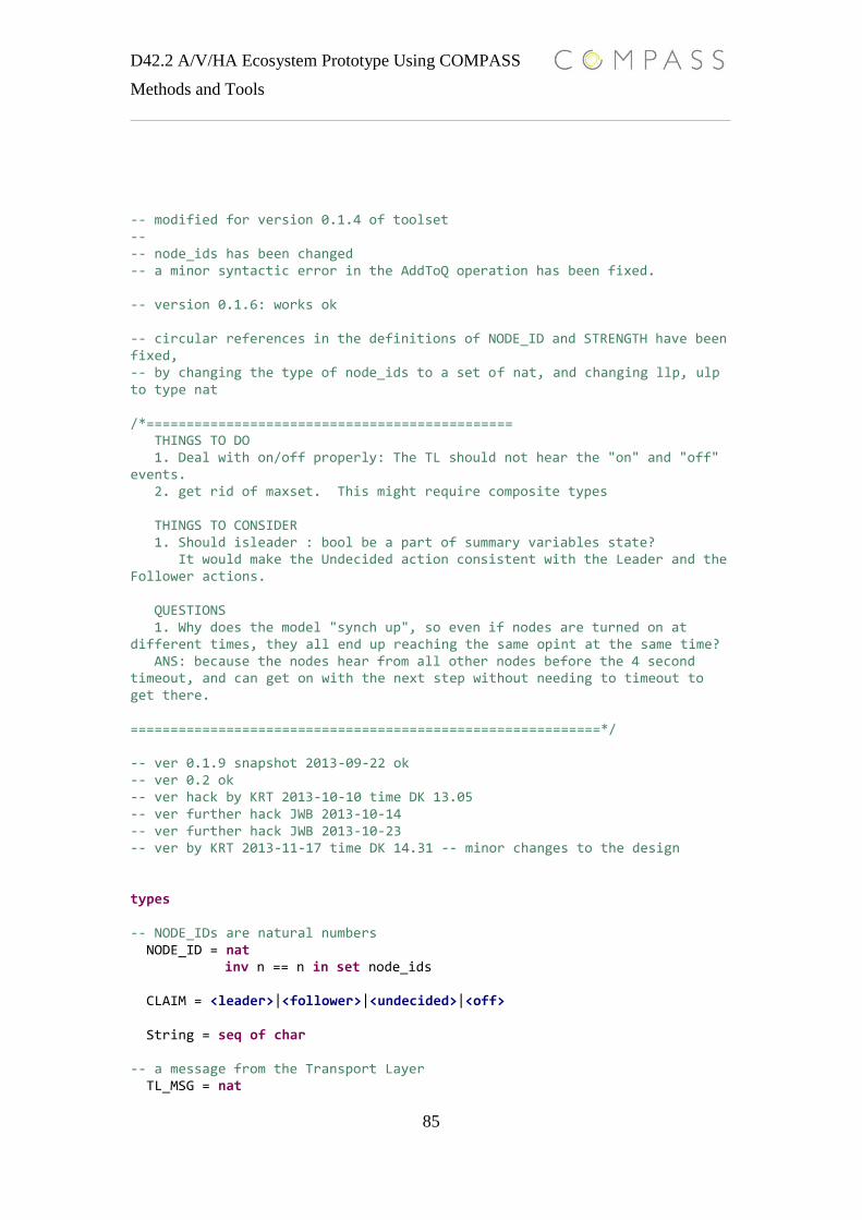
D42.2 A/V/HA Ecosystem Prototype Using COMPASS
Methods and Tools
85
-- modified for version 0.1.4 of toolset -- -- node_ids has been changed -- a minor syntactic error in the AddToQ operation has been fixed. -- version 0.1.6: works ok -- circular references in the definitions of NODE_ID and STRENGTH have been fixed, -- by changing the type of node_ids to a set of nat, and changing llp, ulp to type nat /*============================================== THINGS TO DO 1. Deal with on/off properly: The TL should not hear the "on" and "off" events. 2. get rid of maxset. This might require composite types THINGS TO CONSIDER 1. Should isleader : bool be a part of summary variables state? It would make the Undecided action consistent with the Leader and the Follower actions. QUESTIONS 1. Why does the model "synch up", so even if nodes are turned on at different times, they all end up reaching the same opint at the same time? ANS: because the nodes hear from all other nodes before the 4 second timeout, and can get on with the next step without needing to timeout to get there. ===========================================================*/ -- ver 0.1.9 snapshot 2013-09-22 ok -- ver 0.2 ok -- ver hack by KRT 2013-10-10 time DK 13.05 -- ver further hack JWB 2013-10-14 -- ver further hack JWB 2013-10-23 -- ver by KRT 2013-11-17 time DK 14.31 -- minor changes to the design types -- NODE_IDs are natural numbers NODE_ID = nat inv n == n in set node_ids CLAIM = <leader>|<follower>|<undecided>|<off> String = seq of char -- a message from the Transport Layer TL_MSG = nat
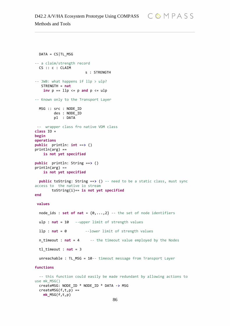
D42.2 A/V/HA Ecosystem Prototype Using COMPASS
Methods and Tools
86
DATA = CS|TL_MSG -- a claim/strength record CS :: c : CLAIM s : STRENGTH -- JWB: what happens if llp > ulp? STRENGTH = nat inv p == llp <= p and p <= ulp -- Known only to the Transport Layer MSG :: src : NODE_ID des : NODE_ID pl : DATA -- wrapper class fro native VDM class class IO = begin operations public println: int ==> () println(arg) == is not yet specified public println: String ==> () println(arg) == is not yet specified public toString: String ==> () -- need to be a static class, must sync access to the native io stream toString(i)== is not yet specified end values node_ids : set of nat = {0,...,2} -- the set of node identifiers ulp : nat = 10 --upper limit of strength values llp : nat = 0 --lower limit of strength values n_timeout : nat = 4 -- the timeout value employed by the Nodes tl_timeout : nat = 3 unreachable : TL_MSG = 10-- timeout message from Transport Layer functions -- this function could easily be made redundant by allowing actions to use mk_MSG() createMSG: NODE_ID * NODE_ID * DATA -> MSG createMSG(f,t,p) == mk_MSG(f,t,p)
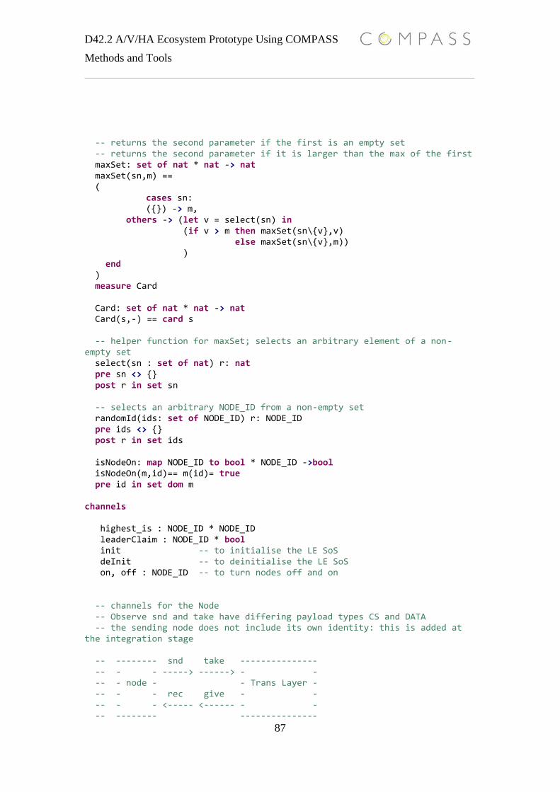
D42.2 A/V/HA Ecosystem Prototype Using COMPASS
Methods and Tools
87
-- returns the second parameter if the first is an empty set -- returns the second parameter if it is larger than the max of the first maxSet: set of nat * nat -> nat maxSet(sn,m) == ( cases sn: ({}) -> m, others -> (let v = select(sn) in (if v > m then maxSet(sn\{v},v) else maxSet(sn\{v},m)) ) end ) measure Card Card: set of nat * nat -> nat Card(s,-) == card s -- helper function for maxSet; selects an arbitrary element of a non-empty set select(sn : set of nat) r: nat pre sn <> {} post r in set sn -- selects an arbitrary NODE_ID from a non-empty set randomId(ids: set of NODE_ID) r: NODE_ID pre ids <> {} post r in set ids isNodeOn: map NODE_ID to bool * NODE_ID ->bool isNodeOn(m,id)== m(id)= true pre id in set dom m channels highest_is : NODE_ID * NODE_ID leaderClaim : NODE_ID * bool init -- to initialise the LE SoS deInit -- to deinitialise the LE SoS on, off : NODE_ID -- to turn nodes off and on -- channels for the Node -- Observe snd and take have differing payload types CS and DATA -- the sending node does not include its own identity: this is added at the integration stage -- -------- snd take --------------- -- - - -----> ------> - - -- - node - - Trans Layer - -- - - rec give - - -- - - <----- <------ - - -- -------- ---------------

D42.2 A/V/HA Ecosystem Prototype Using COMPASS
Methods and Tools
88
n_send : NODE_ID * NODE_ID * DATA -- from * to * payload n_rec : NODE_ID * NODE_ID * DATA -- to * from * payload process Node = i : nat @ begin state -- State is divided into immutable, volatile and summary memory. id : NODE_ID := i -- the ID of the node: immutable state -- mem is volatile memory mem: map NODE_ID to CS := { cid |-> mk_CS(<off>, 0) | cid in set node_ids \ {id} } -- the map of node ids to their CSs, using mk_CS(<off>, 0) instead of nil inv dom mem = node_ids \ {id} and -- the domain of mem must not include id (the ID of the node) dom mem <> {} -- must be more than one node in the network (although this model -- should work if there is only one node) -- below are summary variables highest_strength : STRENGTH := 0 -- the highest strength of leadership claim node is aware of highest_strength_id : NODE_ID := 0 -- id of node making the leadership claim with the highest strength -- this is allowed to be any node id, including id itself inv highest_strength_id in set (dom mem union {id}) leaders : nat := 0 -- the leader count among my neighbours inv leaders <= card dom mem myCS : CS := mk_CS(<off>, 0) -- my claim/strength pair myNeighbours : seq of NODE_ID := [d| d in set dom mem @ d <>id] operations Init: () ==> () Init() == ( id := i; -- initialise id with the paramater passed to Node at its instantiation flushState() -- flush volatile and summary memory )

D42.2 A/V/HA Ecosystem Prototype Using COMPASS
Methods and Tools
89
flushState: () ==> () flushState() == ( mem := { cid |-> mk_CS(<off>, 0) | cid in set node_ids \ {id} }; highest_strength := 0; highest_strength_id := if id=0 then 1 else 0; -- krt. need to make this generic for all nodes, the real impl use mac adress values leaders := 0; myCS := mk_CS(<off>, 0) ) -- used by controller to write a CS to a memory cell write: NODE_ID * DATA ==> () write(d,dat) == ( if is_TL_MSG(dat) then mem(d) := mk_CS(<off>,0) else mem(d) := dat -- tmp impl, currently the IDE do not support case statements /*cases dat: TL_MSG -> mem(i) := mk_CS(<off>,0), -- if we receive a message from the TL we record that the node is off CS -> mem(i) := dat -- if a claim/strength pair we add it to memory end*/ ) pre d in set dom mem post mem(d) = dat or mem(d).c = <off> update:()==>() update() == ( leaders := card{n|n in set dom mem @ mem(n).c = <leader>}; highest_strength := maxStrength(); -- highest strength among leadership claims; 0 is no leadership claims. highest_strength_id := maxStrengthID() -- id of highest strength among the leadership claims, 0 or 1 if no leadership claims ) post leaders > 0 => mem(highest_strength_id).s = highest_strength -- this only returns the maximum strength among the leadership claims maxStrength:() ==> nat maxStrength() == ( dcl strs : set of nat := {cs.s|cs in set rng mem @ cs.c = <leader>} @ return maxSet(strs,0) ) -- return the ID of the leader with the max strength; minId if there are no leaders maxStrengthID : () ==> NODE_ID maxStrengthID() ==
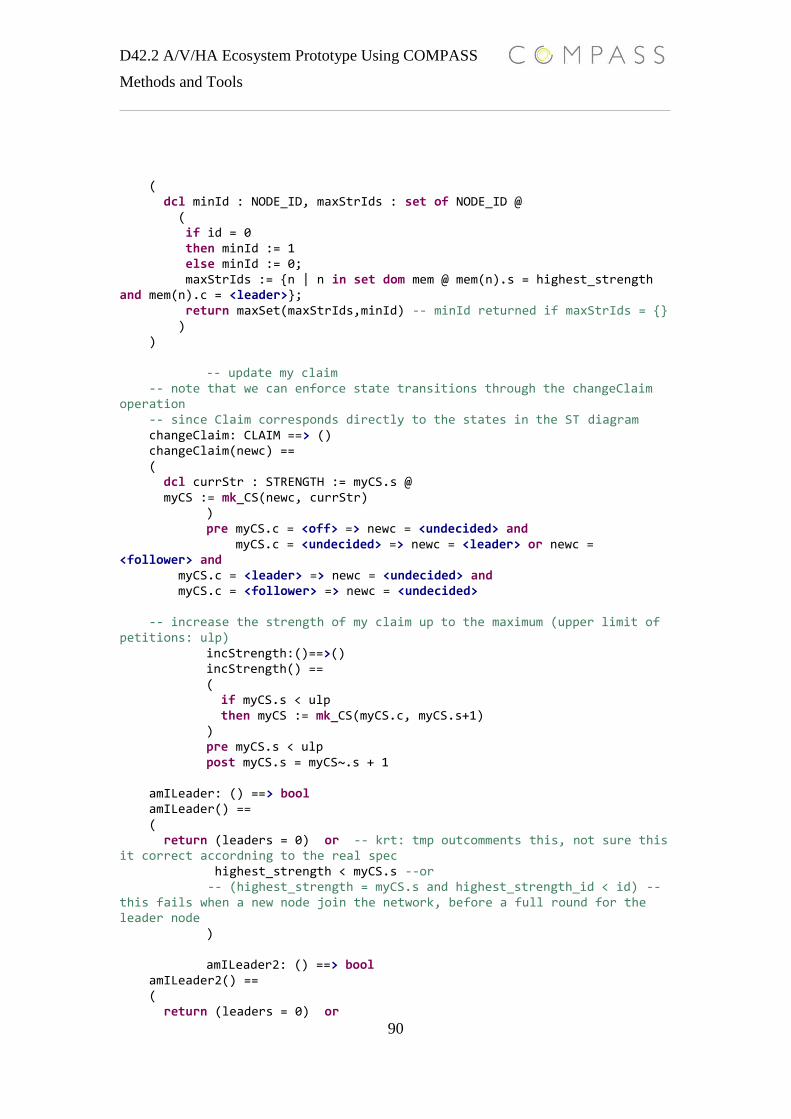
D42.2 A/V/HA Ecosystem Prototype Using COMPASS
Methods and Tools
90
( dcl minId : NODE_ID, maxStrIds : set of NODE_ID @ ( if id = 0 then minId := 1 else minId := 0; maxStrIds := {n | n in set dom mem @ mem(n).s = highest_strength and mem(n).c = <leader>}; return maxSet(maxStrIds,minId) -- minId returned if maxStrIds = {} ) ) -- update my claim -- note that we can enforce state transitions through the changeClaim operation -- since Claim corresponds directly to the states in the ST diagram changeClaim: CLAIM ==> () changeClaim(newc) == ( dcl currStr : STRENGTH := myCS.s @ myCS := mk_CS(newc, currStr) ) pre myCS.c = <off> => newc = <undecided> and myCS.c = <undecided> => newc = <leader> or newc = <follower> and myCS.c = <leader> => newc = <undecided> and myCS.c = <follower> => newc = <undecided> -- increase the strength of my claim up to the maximum (upper limit of petitions: ulp) incStrength:()==>() incStrength() == ( if myCS.s < ulp then myCS := mk_CS(myCS.c, myCS.s+1) ) pre myCS.s < ulp post myCS.s = myCS~.s + 1 amILeader: () ==> bool amILeader() == ( return (leaders = 0) or -- krt: tmp outcomments this, not sure this it correct accordning to the real spec highest_strength < myCS.s --or -- (highest_strength = myCS.s and highest_strength_id < id) -- this fails when a new node join the network, before a full round for the leader node ) amILeader2: () ==> bool amILeader2() == ( return (leaders = 0) or
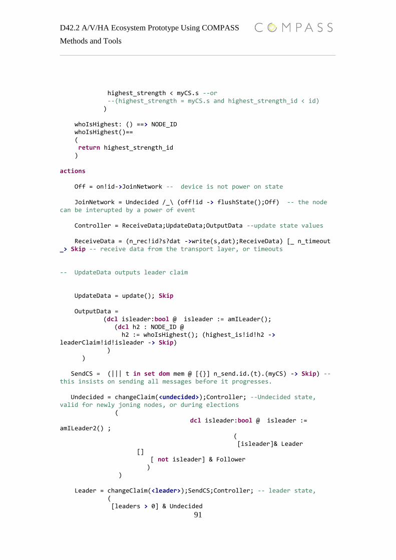
D42.2 A/V/HA Ecosystem Prototype Using COMPASS
Methods and Tools
91
highest_strength < myCS.s --or --(highest_strength = myCS.s and highest_strength_id < id) ) whoIsHighest: () ==> NODE_ID whoIsHighest()== ( return highest_strength_id ) actions Off = on!id->JoinNetwork -- device is not power on state JoinNetwork = Undecided /_\ (off!id -> flushState();Off) -- the node can be interupted by a power of event Controller = ReceiveData;UpdateData;OutputData --update state values ReceiveData = (n_rec!id?s?dat ->write(s,dat);ReceiveData) [_ n_timeout _> Skip -- receive data from the transport layer, or timeouts -- UpdateData outputs leader claim UpdateData = update(); Skip OutputData = (dcl isleader:bool @ isleader := amILeader(); (dcl h2 : NODE_ID @ h2 := whoIsHighest(); (highest_is!id!h2 -> leaderClaim!id!isleader -> Skip) ) ) SendCS = (||| t in set dom mem @ [{}] n_send.id.(t).(myCS) -> Skip) -- this insists on sending all messages before it progresses. Undecided = changeClaim(<undecided>);Controller; --Undecided state, valid for newly joning nodes, or during elections ( dcl isleader:bool @ isleader := amILeader2() ; ( [isleader]& Leader [] [ not isleader] & Follower ) ) Leader = changeClaim(<leader>);SendCS;Controller; -- leader state, ( [leaders > 0] & Undecided

D42.2 A/V/HA Ecosystem Prototype Using COMPASS
Methods and Tools
92
[] [leaders = 0] & incStrength();Leader ) Follower = changeClaim(<follower>);flushState(); Controller; -- krt: a follower do not send status out, followers are only listing on the leader ( -- add logic for hadndling the leader turning of--flust the current stae valuesm before updating [leaders >1 or leaders=0 ] & Undecided [] [leaders = 1] & Follower ) @ init -> Init();(Off/_\deInit->Skip) -- main entry point for a node, need the deInit channel for testing deadlock/livelock freedom end -- process representing the IP transport layer, simulate the multicast logic using in the B&O SoS process TransportLayerProc = begin state nodeOn : map NODE_ID to bool := {n |-> false | n in set node_ids} inv dom nodeOn = node_ids and card(dom nodeOn) >= 2 -- the queue of messages in the TL queue : seq of MSG := [] operations Init:() ==> () Init() == ( nodeOn := {n |-> false | n in set node_ids}; queue := [] ) post dom nodeOn = node_ids and rng nodeOn = {false} and queue = [] -- JWB: added an inv to say that the rest of the queue hasn't changed addToQ: MSG ==> () addToQ(m) == ( queue := queue ^ [m] ) post len queue = len queue~ + 1 and queue(len queue) = m and queue~ = queue(1,...,len queue - 1)

D42.2 A/V/HA Ecosystem Prototype Using COMPASS
Methods and Tools
93
-- JWB: added an inv to say that the rest of the queue hasn't changed getNext:() ==> MSG getNext() == ( let h = hd(queue) in ( queue := tl(queue); return h ) ) pre queue <> [] post len queue = len queue~ - 1 and queue = tl(queue~) setNodeOff:(NODE_ID) ==> () setNodeOff(nId) == ( nodeOn(nId) := false ) pre nId in set dom nodeOn post nodeOn(nId) = false setNodeOn:(NODE_ID) ==> () setNodeOn(nId) == ( nodeOn(nId) := true ) pre nId in set dom nodeOn post nodeOn(nId) = true getQueue:() ==> seq of MSG getQueue() == (return queue) actions TransportLayerLoop = mu X @ (TransportLayer;X) TransportLayer = (Reader [] Writer [] NodeMngt) Reader = n_send?fr?too?payload -> (setNodeOn(fr); (dcl m:MSG @ m := createMSG(fr,too,payload); addToQ(m); Skip) ) Writer = [queue <> [] ] & (dcl m:MSG, nodeIsOn: bool @ m := getNext(); nodeIsOn := isNodeOn(nodeOn,m.des); ( [nodeIsOn] & ( (n_rec!(m.des)!(m.src)!(m.pl) -> Skip) [_ tl_timeout _> setNodeOff(m.des);

D42.2 A/V/HA Ecosystem Prototype Using COMPASS
Methods and Tools
94
(if not (m.pl=unreachable) then (dcl rep : MSG @ rep := createMSG((m.des),(m.src),unreachable); addToQ(rep))); Skip ) [] [not nodeIsOn] & ( (if not (m.pl=unreachable) then (dcl rep : MSG @ rep := createMSG((m.des),(m.src),unreachable); addToQ(rep))); Skip ) ) ) NodeMngt = on?i -> setNodeOn(i);Skip [] off?i -> setNodeOff(i);Skip @ init -> Init();(TransportLayerLoop /_\deInit->Skip) end -- process with all nodes process AllNodes = [|{|init,deInit|}|] i in set node_ids @ (Node(i)) -- SoS process combining the nodes and the network layer process SoS_Election = AllNodes[|{|n_send,n_rec,on,off,init,deInit|}|]TransportLayerProc --process for testing the hidding operator-- currently not working process ElectionHiddenComms = AllNodes[|{|n_send,n_rec,on,off,init|}|]TransportLayerProc \\ {|n_rec,n_send|} -------------------------------------------------------------------------------------------------------------------------------- -- test section process RunTest = Test [|{|n_send,n_rec,on,off,init|}|] SoS_Election -- legal traces for election node validation process Test = begin actions Test1 = init -> Stop Test2 = init-> on.0-> highest_is.(0).(1)->leaderClaim.(0).(true)->Step2 Step2 = (dcl c:CS := mk_CS(<leader>, 0)@ n_send.(0).(1).(c)->n_send.(0).(2).(c)->off.0->deInit->Skip) @ Test2 end -- test SoS for validation of test traces process TestLeaderNode = Test [|{|n_send,n_rec,on,off,init,highest_is,leaderClaim,deInit|}|] SoS_Election
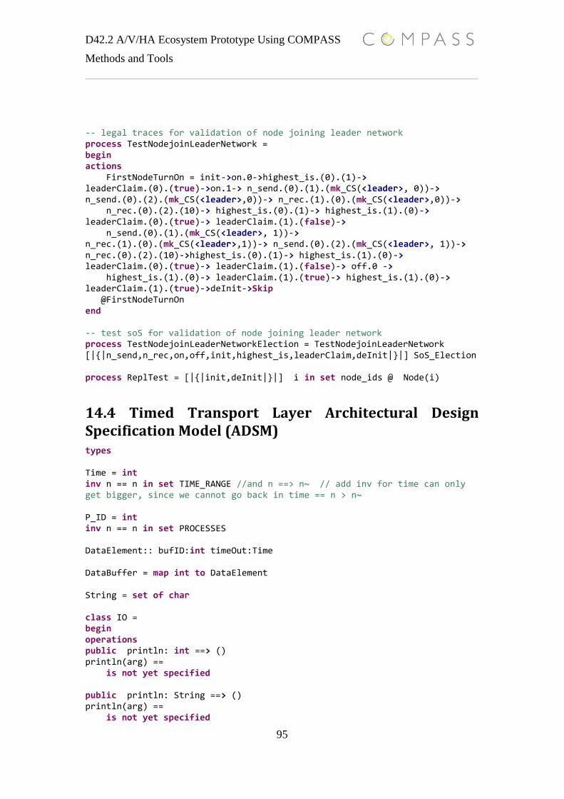
D42.2 A/V/HA Ecosystem Prototype Using COMPASS
Methods and Tools
95
-- legal traces for validation of node joining leader network process TestNodejoinLeaderNetwork = begin actions FirstNodeTurnOn = init->on.0->highest_is.(0).(1)-> leaderClaim.(0).(true)->on.1-> n_send.(0).(1).(mk_CS(<leader>, 0))-> n_send.(0).(2).(mk_CS(<leader>,0))-> n_rec.(1).(0).(mk_CS(<leader>,0))-> n_rec.(0).(2).(10)-> highest_is.(0).(1)-> highest_is.(1).(0)-> leaderClaim.(0).(true)-> leaderClaim.(1).(false)-> n_send.(0).(1).(mk_CS(<leader>, 1))-> n_rec.(1).(0).(mk_CS(<leader>,1))-> n_send.(0).(2).(mk_CS(<leader>, 1))-> n_rec.(0).(2).(10)->highest_is.(0).(1)-> highest_is.(1).(0)-> leaderClaim.(0).(true)-> leaderClaim.(1).(false)-> off.0 -> highest_is.(1).(0)-> leaderClaim.(1).(true)-> highest_is.(1).(0)-> leaderClaim.(1).(true)->deInit->Skip @FirstNodeTurnOn end -- test soS for validation of node joining leader network process TestNodejoinLeaderNetworkElection = TestNodejoinLeaderNetwork [|{|n_send,n_rec,on,off,init,highest_is,leaderClaim,deInit|}|] SoS_Election process ReplTest = [|{|init,deInit|}|] i in set node_ids @ Node(i)
14.4 Timed Transport Layer Architectural Design Specification Model (ADSM) types Time = int inv n == n in set TIME_RANGE //and n ==> n~ // add inv for time can only get bigger, since we cannot go back in time == n > n~ P_ID = int inv n == n in set PROCESSES DataElement:: bufID:int timeOut:Time DataBuffer = map int to DataElement String = set of char class IO = begin operations public println: int ==> () println(arg) == is not yet specified public println: String ==> () println(arg) == is not yet specified
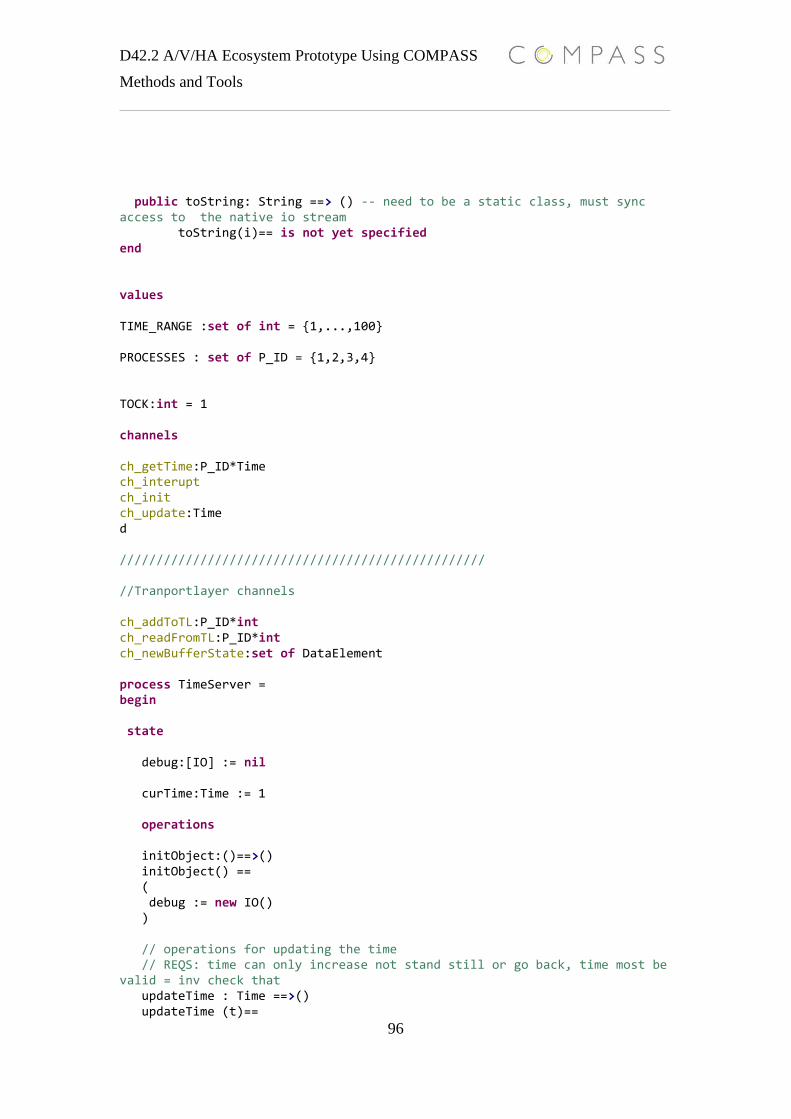
D42.2 A/V/HA Ecosystem Prototype Using COMPASS
Methods and Tools
96
public toString: String ==> () -- need to be a static class, must sync access to the native io stream toString(i)== is not yet specified end values TIME_RANGE :set of int = {1,...,100} PROCESSES : set of P_ID = {1,2,3,4} TOCK:int = 1 channels ch_getTime:P_ID*Time ch_interupt ch_init ch_update:Time d ////////////////////////////////////////////////// //Tranportlayer channels ch_addToTL:P_ID*int ch_readFromTL:P_ID*int ch_newBufferState:set of DataElement process TimeServer = begin state debug:[IO] := nil curTime:Time := 1 operations initObject:()==>() initObject() == ( debug := new IO() ) // operations for updating the time // REQS: time can only increase not stand still or go back, time most be valid = inv check that updateTime : Time ==>() updateTime (t)==

D42.2 A/V/HA Ecosystem Prototype Using COMPASS
Methods and Tools
97
( curTime:= curTime +t ) pre curTime+ t > curTime and curTime+ t in set TIME_RANGE post curTime > curTime~ and curTime in set TIME_RANGE actions act_tick_tock = t:Time @ ( Wait(TOCK);(updateTime(TOCK));act_main (curTime) // add time out time never stops :-) ) act_OfferCurrentTime = t:Time @ ( ||| p in set PROCESSES @ [{}] act_offerTimeLoop(t,p) ) act_offerTimeLoop = t:Time, p:P_ID @ ( mu X @ (ch_getTime.(p)!t->X [_ TOCK _> Skip ) ) act_main = t:Time @ (act_tick_tock(t)[|{||}|] act_OfferCurrentTime (t)) @ch_init -> initObject(); (act_main (curTime) /_\ ch_init->Skip) end process TimeReader = id:P_ID @ begin actions main = mu X @ (ch_getTime.id?x->X) @ ch_init->(main /_\ ch_init->Skip) end process TimeCSs = [|{|ch_init|}|] i in set PROCESSES @ (TimeReader(i)) process TimeSoS = TimeServer [|{|ch_init,ch_getTime|}|] TimeCSs ///////////////////////////////////////////////////////////////////////////////////////////////////////////////////////////// //section for process TimedBufferTransportLayer = begin state
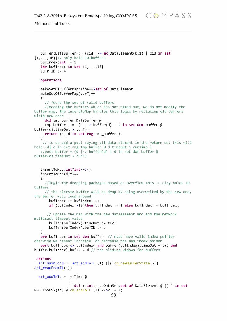
D42.2 A/V/HA Ecosystem Prototype Using COMPASS
Methods and Tools
98
buffer:DataBuffer := {cid |-> mk_DataElement(0,1) | cid in set {1,...,10}}// only hold 10 buffers bufIndex:int := 1 inv bufIndex in set {1,...,10} id:P_ID := 4 operations makeSetOfBufferMap:Time==>set of DataElement makeSetOfBufferMap(curT)== ( // found the set of valid buffers //meaning the buffers which has not timed out, we do not modify the buffer map, the inserttoMap handles this logic by replacing old buffers wicth new ones dcl tmp_buffer:DataBuffer @ tmp_buffer := {d |-> buffer(d) | d in set dom buffer @ buffer(d).timeOut > curT}; return {d| d in set rng tmp_buffer } ) // to do add a post saying all data element in the return set this will hold {d| d in set rng tmp_buffer @ d.timeOut > curTime } //post buffer = {d |-> buffer(d) | d in set dom buffer @ buffer(d).timeOut > curT} insertToMap:int*int==>() insertToMap(d,t)== ( //logic for dropping packages based on overflow this TL olny holds 10 buffers // the oldeste buffer will be drop bu being overwrited by the new one, the buffer will loop around bufIndex := bufIndex +1; if (bufIndex >10)then bufIndex := 1 else bufIndex := bufIndex; // update the map with the new dataelement and add the network multicast timeout value buffer(bufIndex).timeOut := t+2; buffer(bufIndex).bufID := d ) pre bufIndex in set dom buffer // must have valid index pointer oherwise we cannot increase or decrease the map index poiner post bufIndex <> bufIndex~ and buffer(bufIndex).timeOut = t+2 and buffer(bufIndex).bufID = d // the sliding widows for buffers actions act_mainLoop = act_addToTL (1) [|{|ch_newBufferState|}|] act_readFromTL({}) act_addToTL = t:Time @ ( dcl x:int, curDataSet:set of DataElement @ [] i in set PROCESSES\{id} @ ch_addToTL.(i)?k->x := k;
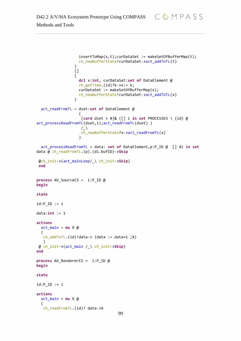
D42.2 A/V/HA Ecosystem Prototype Using COMPASS
Methods and Tools
99
insertToMap(x,t);curDataSet := makeSetOfBufferMap(t); ch_newBufferState!curDataSet->act_addToTL(t) ) [] ( dcl x:int, curDataSet:set of DataElement @ ch_getTime.(id)?k->x:= k; curDataSet := makeSetOfBufferMap(x); ch_newBufferState!curDataSet->act_addToTL(x) ) act_readFromTL = dset:set of DataElement @ ( [card dset > 0]& ([] i in set PROCESSES \ {id} @ act_processReadFromTL(dset,i);act_readFromTL(dset) ) /_\ ch_newBufferState?x->act_readFromTL(x) ) act_processReadFromTL = data: set of DataElement,p:P_ID @ [] di in set data @ ch_readFromTL.(p).(di.bufID)->Skip @ch_init->(act_mainLoop/_\ ch_init->Skip) end process AV_SourceCS = i:P_ID @ begin state id:P_ID := i data:int := 1 actions act_main = mu X @ ( ch_addToTL.(id)!data-> (data := data+1 ;X) ) @ ch_init->(act_main /_\ ch_init->Skip) end process AV_RendererCS = i:P_ID @ begin state id:P_ID := i actions act_main = mu X @ ( ch_readFromTL.(id)? data->X

D42.2 A/V/HA Ecosystem Prototype Using COMPASS
Methods and Tools
100
) @ ch_init->(act_main /_\ ch_init->Skip) end process TimedMultiCastNetwork = TimedBufferTransportLayer [|{|ch_getTime,ch_init|}|]TimeServer process AV_SourceAndMulticastNetwork = TimedMultiCastNetwork [|{|ch_addToTL,ch_init|}|] AV_SourceCS(1) process AV_Renderers = [|{|ch_init|}|] i in set{2,3} @ AV_RendererCS(i) process AV_MulticastNetwork = AV_SourceAndMulticastNetwork [|{|ch_readFromTL,ch_init|}|] AV_Renderers
14.5 OO CML Design Pattern model types ID=nat String = seq of char FactoryEvent = <GET>|<EXIT> -- wrapper class fro native VDM class class IO = begin operations public println: int ==> () println(arg) == is not yet specified public println: String ==> () println(arg) == is not yet specified public toString: int ==> () -- need to be a static class, must sync access to the native io stream toString(i)== Skip end class DataPackage = begin state public send_to: set of ID := {} public send_from:ID := 0 public data: [DataObject] := nil end
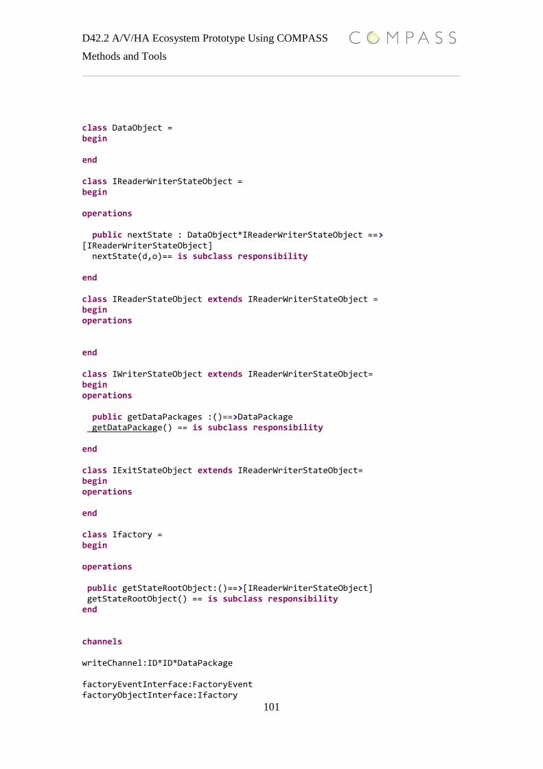
D42.2 A/V/HA Ecosystem Prototype Using COMPASS
Methods and Tools
101
class DataObject = begin end class IReaderWriterStateObject = begin operations public nextState : DataObject*IReaderWriterStateObject ==> [IReaderWriterStateObject] nextState(d,o)== is subclass responsibility end class IReaderStateObject extends IReaderWriterStateObject = begin operations end class IWriterStateObject extends IReaderWriterStateObject= begin operations public getDataPackages :()==>DataPackage getDataPackage() == is subclass responsibility end class IExitStateObject extends IReaderWriterStateObject= begin operations end class Ifactory = begin operations public getStateRootObject:()==>[IReaderWriterStateObject] getStateRootObject() == is subclass responsibility end channels writeChannel:ID*ID*DataPackage factoryEventInterface:FactoryEvent factoryObjectInterface:Ifactory
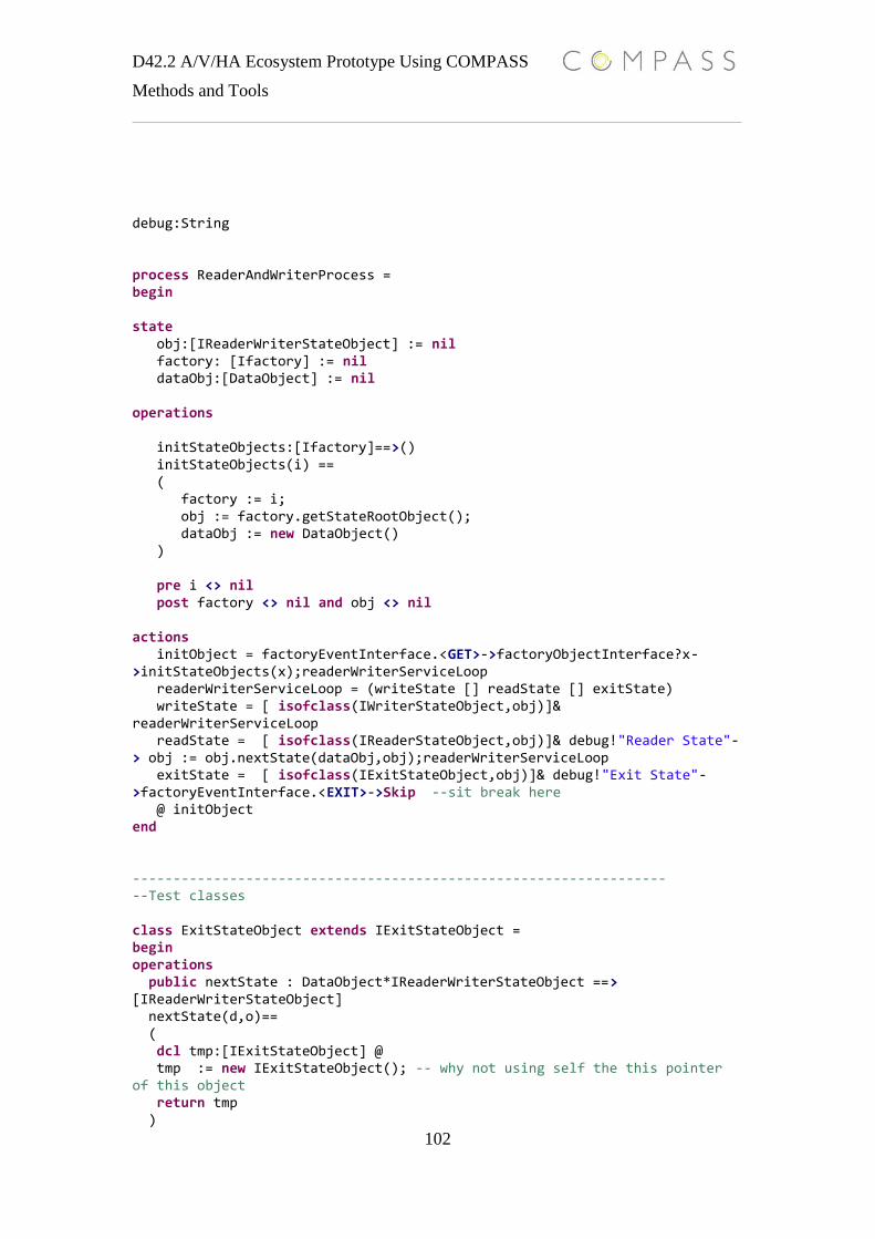
D42.2 A/V/HA Ecosystem Prototype Using COMPASS
Methods and Tools
102
debug:String process ReaderAndWriterProcess = begin state obj:[IReaderWriterStateObject] := nil factory: [Ifactory] := nil dataObj:[DataObject] := nil operations initStateObjects:[Ifactory]==>() initStateObjects(i) == ( factory := i; obj := factory.getStateRootObject(); dataObj := new DataObject() ) pre i <> nil post factory <> nil and obj <> nil actions initObject = factoryEventInterface.<GET>->factoryObjectInterface?x->initStateObjects(x);readerWriterServiceLoop readerWriterServiceLoop = (writeState [] readState [] exitState) writeState = [ isofclass(IWriterStateObject,obj)]& readerWriterServiceLoop readState = [ isofclass(IReaderStateObject,obj)]& debug!"Reader State"-> obj := obj.nextState(dataObj,obj);readerWriterServiceLoop exitState = [ isofclass(IExitStateObject,obj)]& debug!"Exit State"->factoryEventInterface.<EXIT>->Skip --sit break here @ initObject end ------------------------------------------------------------------ --Test classes class ExitStateObject extends IExitStateObject = begin operations public nextState : DataObject*IReaderWriterStateObject ==> [IReaderWriterStateObject] nextState(d,o)== ( dcl tmp:[IExitStateObject] @ tmp := new IExitStateObject(); -- why not using self the this pointer of this object return tmp )
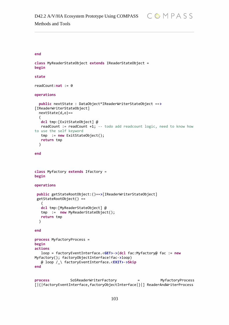
D42.2 A/V/HA Ecosystem Prototype Using COMPASS
Methods and Tools
103
end class MyReaderStateObject extends IReaderStateObject = begin state readCount:nat := 0 operations public nextState : DataObject*IReaderWriterStateObject ==> [IReaderWriterStateObject] nextState(d,o)== ( dcl tmp:[ExitStateObject] @ readCount := readCount +1; -- todo add readcount logic, need to know how to use the self keyword tmp := new ExitStateObject(); return tmp ) end class Myfactory extends Ifactory = begin operations public getStateRootObject:()==>[IReaderWriterStateObject] getStateRootObject() == ( dcl tmp:[MyReaderStateObject] @ tmp := new MyReaderStateObject(); return tmp ) end process MyfactoryProcess = begin actions loop = factoryEventInterface.<GET>->(dcl fac:Myfactory@ fac := new Myfactory(); factoryObjectInterface!fac->loop) @ loop /_\ factoryEventInterface.<EXIT>->Skip end process SoSReaderWriterFactory = MyfactoryProcess [|{|factoryEventInterface,factoryObjectInterface|}|] ReaderAndWriterProcess

D42.2 A/V/HA Ecosystem Prototype Using COMPASS
Methods and Tools
104
14.6 OO Clock Domain Model types String = seq of char class IO = begin operations public println: int ==> () println(arg) == is not yet specified public println: String ==> () println(arg) == is not yet specified public toString: int ==> () -- need to be a static class, must sync access to the native io stream toString(i)== Skip end class IClockDomain = begin state protected feq:nat := 1 protected time:nat := 0 operations public setFeq:nat==>() setFeq(t)== feq := t public tick:()==>() tick()== time := time+feq public getTime:()==>nat getTime() == return time public getTickTime:()==>nat getTickTime () == return feq end channels ClockDomainFac:nat ClockDomainCreate: IClockDomain init c

D42.2 A/V/HA Ecosystem Prototype Using COMPASS
Methods and Tools
105
ClientGetLocalTime:nat localClockDomainInterface: nat*nat debug:String*nat process ClockDomainFactory = begin state obj:[IClockDomain] := nil operations createclockDomainObject:nat ==>() createclockDomainObject(id)== ( obj := new IClockDomain() ) actions factoryServiceLoop = (ClockDomainFac?x->createclockDomainObject(x);ClockDomainCreate!obj->factoryServiceLoop) @ init->(factoryServiceLoop /_\ init->Skip) end process ClockDomain = objID:nat@ begin state clockDomainObj:[IClockDomain] := nil tickTime:nat := 0 clockDomainID: nat := objID actions getClockDomain_state = ( ClockDomainFac!objID->ClockDomainCreate?x->clockDomainObj := x; clockDomainObj.setFeq(objID); startClockDomainTickAndClockDomainService_state ) startClockDomainTickAndClockDomainService_state = tockLogic [|{localClockDomainInterface}|] getLocalTimeService_state tockLogic = tock_state;tockLogic tock_state =
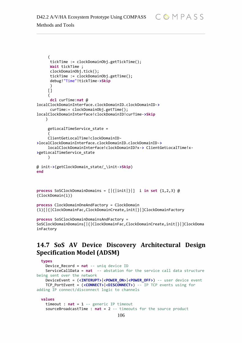
D42.2 A/V/HA Ecosystem Prototype Using COMPASS
Methods and Tools
106
( tickTime := clockDomainObj.getTickTime(); Wait tickTime ; clockDomainObj.tick(); tickTime := clockDomainObj.getTime(); debug!"Time"!tickTime->Skip ) [] ( dcl curTime:nat @ localClockDomainInterface.clockDomainID.clockDomainID-> curTime:= clockDomainObj.getTime(); localClockDomainInterface!clockDomainID!curTime->Skip ) getLocalTimeService_state = ( ClientGetLocalTime!clockDomainID->localClockDomainInterface.clockDomainID.clockDomainID-> localClockDomainInterface!clockDomainID?x-> ClientGetLocalTime!x->getLocalTimeService_state ) @ init->(getClockDomain_state/_\init->Skip) end process SoSClockDomainDomains = [|{|init|}|] i in set {1,2,3} @ (ClockDomain(i)) process ClockDomainOneAndFactory = ClockDomain (1)[|{|ClockDomainFac,ClockDomainCreate,init|}|]ClockDomainFactory process SoSClockDomainDomainsAndFactory = SoSClockDomainDomains[|{|ClockDomainFac,ClockDomainCreate,init|}|]ClockDomainFactory
14.7 SoS AV Device Discovery Architectural Design Specification Model (ADSM) types Device_Record = nat -- uniq device ID ServiceCallData = nat -- abstation for the service call data structure being sent over the network DeviceEvent = (<INTERUPT>|<POWER_ON>|<POWER_OFF>) -- user device event TCP_PortEvent = (<CONNECT>|<DISCONNECT>) -- IP TCP events using for adding IP connect/disconnect logic to channels values timeout : nat = 1 -- generic IP timeout sourceBroadcastTime : nat = 2 -- timeouts for the source product
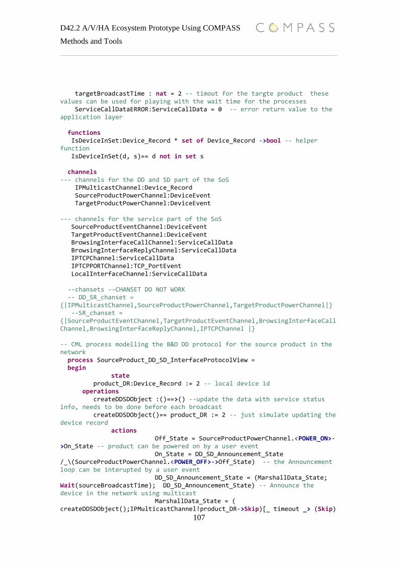
D42.2 A/V/HA Ecosystem Prototype Using COMPASS
Methods and Tools
107
targetBroadcastTime : nat = 2 -- timout for the targte product these values can be used for playing with the wait time for the processes ServiceCallDataERROR:ServiceCallData = 0 -- error return value to the application layer functions IsDeviceInSet:Device_Record * set of Device_Record ->bool -- helper function IsDeviceInSet(d, s)== d not in set s channels --- channels for the DD and SD part of the SoS IPMulticastChannel:Device_Record SourceProductPowerChannel:DeviceEvent TargetProductPowerChannel:DeviceEvent --- channels for the service part of the SoS SourceProductEventChannel:DeviceEvent TargetProductEventChannel:DeviceEvent BrowsingInterfaceCallChannel:ServiceCallData BrowsingInterfaceReplyChannel:ServiceCallData IPTCPChannel:ServiceCallData IPTCPPORTChannel:TCP_PortEvent LocalInterfaceChannel:ServiceCallData --chansets --CHANSET DO NOT WORK -- DD_SR_chanset = {|IPMulticastChannel,SourceProductPowerChannel,TargetProductPowerChannel|} --SR_chanset = {|SourceProductEventChannel,TargetProductEventChannel,BrowsingInterfaceCallChannel,BrowsingInterfaceReplyChannel,IPTCPChannel |} -- CML process modelling the B&O DD protocol for the source product in the network process SourceProduct_DD_SD_InterfaceProtocolView = begin state product_DR:Device_Record := 2 -- local device id operations createDDSDObject :()==>() --update the data with service status info, needs to be done before each broadcast createDDSDObject()== product_DR := 2 -- just simulate updating the device record actions Off_State = SourceProductPowerChannel.<POWER_ON>->On_State -- product can be powered on by a user event On_State = DD_SD_Announcement_State /_\(SourceProductPowerChannel.<POWER_OFF>->Off_State) -- the Announcement loop can be interupted by a user event DD_SD_Announcement_State = (MarshallData_State; Wait(sourceBroadcastTime); DD_SD_Announcement_State) -- Announce the device in the network using multicast MarshallData_State = ( createDDSDObject();IPMulticastChannel!product_DR->Skip)[_ timeout _> (Skip)

D42.2 A/V/HA Ecosystem Prototype Using COMPASS
Methods and Tools
108
--- simulate IP multicast logic using timeouts @ Off_State end -- CML process modelling the B&O DD protocol for the target product in the network process TargetProduct_DD_SD_InterfaceProtocolView = begin state product_DRs:set of Device_Record := {} -- set of Ddiscoveed products operations resetProductSet:()==>()-- reset the device set then the product is power on resetProductSet() == product_DRs := {} updateProductSet:Device_Record==>()-- add device to the set, if the pre condition holds updateProductSet(dr)== product_DRs := product_DRs union {dr} pre dr not in set product_DRs post dr in set product_DRs actions Off_State = resetProductSet(); TargetProductPowerChannel.<POWER_ON>->On_State -- the product if off== not visable in the network On_State = Start_Discovery_State /_\(TargetProductPowerChannel.<POWER_OFF>->Off_State) -- product on = try finding other B&O product. in this state the product can be power of by a user event Start_Discovery_State = (DD_SD_Discovery_State ; Wait(targetBroadcastTime) ; Start_Discovery_State)--run the Discovery logic DD_SD_Discovery_State = (IPMulticastChannel?pr->if not IsDeviceInSet(pr,product_DRs) then updateProductSet(pr); Skip )[_ timeout _> (Skip) @ Off_State -- simulate IP multicast logic using timeouts end -- SoS leveel process, contaning one source- and one target product process Beo_DD_SD_InterfaceProtocolViews = SourceProduct_DD_SD_InterfaceProtocolView [|{IPMulticastChannel}|]TargetProduct_DD_SD_InterfaceProtocolView --- test process for playing the SoS level process process Test_TurnOnProduct = begin actions SoS_On = SourceProductPowerChannel.<POWER_ON>->TargetProductPowerChannel.<POWER_ON>->Wait 5;SoS_Off
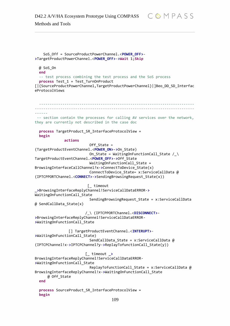
D42.2 A/V/HA Ecosystem Prototype Using COMPASS
Methods and Tools
109
SoS_Off = SourceProductPowerChannel.<POWER_OFF>->TargetProductPowerChannel.<POWER_OFF>->Wait 1;Skip @ SoS_On end -- test process combining the test process and the SoS process process Test_1 = Test_TurnOnProduct [|{SourceProductPowerChannel,TargetProductPowerChannel}|]Beo_DD_SD_InterfaceProtocolViews ---------------------------------------------------------------------------------------------------------------------------------------------------------- -- section contain the processes for calling AV services over the network, they are currently not described in the case doc process TargetProduct_SR_InterfaceProtocolView = begin actions Off_State = (TargetProductEventChannel.<POWER_ON>->On_State) On_State = WaitingOnFunctionCall_State /_\ TargetProductEventChannel.<POWER_OFF>->Off_State WaitingOnFunctionCall_State = BrowsingInterfaceCallChannel?x->ConnectToDevice_State(x) ConnectToDevice_State= x:ServiceCallData @ (IPTCPPORTChannel.<CONNECT>->SendingBrowsingRequest_State(x)) [_ timeout _>BrowsingInterfaceReplyChannel!ServiceCallDataERROR-> WaitingOnFunctionCall_State SendingBrowsingRequest_State = x:ServiceCallData @ SendCallData_State(x) /_\ (IPTCPPORTChannel.<DISCONNECT>->BrowsingInterfaceReplyChannel!ServiceCallDataERROR->WaitingOnFunctionCall_State [] TargetProductEventChannel.<INTERUPT>->WaitingOnFunctionCall_State) SendCallData_State = x:ServiceCallData @ (IPTCPChannel!x->IPTCPChannel?y->ReplayTofunctionCall_State(y)) [_ timeout _> BrowsingInterfaceReplyChannel!ServiceCallDataERROR->WaitingOnFunctionCall_State ReplayTofunctionCall_State = x:ServiceCallData @ BrowsingInterfaceReplyChannel!x->WaitingOnFunctionCall_State @ Off_State end process SourceProduct_SR_InterfaceProtocolView = begin
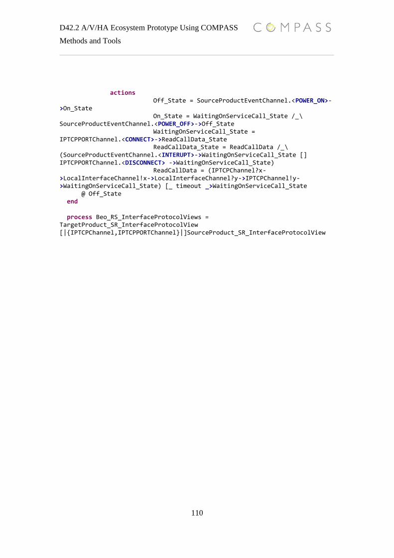
D42.2 A/V/HA Ecosystem Prototype Using COMPASS
Methods and Tools
110
actions Off_State = SourceProductEventChannel.<POWER_ON>->On_State On_State = WaitingOnServiceCall_State /_\ SourceProductEventChannel.<POWER_OFF>->Off_State WaitingOnServiceCall_State = IPTCPPORTChannel.<CONNECT>->ReadCallData_State ReadCallData_State = ReadCallData /_\ (SourceProductEventChannel.<INTERUPT>->WaitingOnServiceCall_State [] IPTCPPORTChannel.<DISCONNECT> ->WaitingOnServiceCall_State) ReadCallData = (IPTCPChannel?x->LocalInterfaceChannel!x->LocalInterfaceChannel?y->IPTCPChannel!y->WaitingOnServiceCall_State) [_ timeout _>WaitingOnServiceCall_State @ Off_State end process Beo_RS_InterfaceProtocolViews = TargetProduct_SR_InterfaceProtocolView [|{IPTCPChannel,IPTCPPORTChannel}|]SourceProduct_SR_InterfaceProtocolView