avibration-relateddesignparameteroptimizationmethodfor
TRANSCRIPT

Research ArticleA Vibration-Related Design Parameter Optimization Method forHigh-Speed Elevator Horizontal Vibration Reduction
Lemiao Qiu 1 Zili Wang 1 Shuyou Zhang 1 Lichun Zhang2 and Jie Chen1
1State Key Laboratory of Fluid Power and Mechatronic Systems Zhejiang University Hangzhou China2Canny Elevator Co Ltd Suzhou China
Correspondence should be addressed to Zili Wang ziliwangzjueducn
Received 13 October 2019 Revised 7 January 2020 Accepted 16 January 2020 Published 13 February 2020
Academic Editor C M Wang
Copyright copy 2020 Lemiao Qiu et al is is an open access article distributed under the Creative Commons Attribution Licensewhich permits unrestricted use distribution and reproduction in any medium provided the original work is properly cited
High-speed elevator horizontal vibration (HsEHV) is a problem that seriously affects ride comfort To solve this problem a designparameter optimization method for HsEHV reduction was studied A dynamic equation of HsEHV was established and itsresponse value was calculated using a precise integration method e influence of the design parameters on horizontal vibrationwas also analyzed An optimization model of the design parameters for HsEHV reduction was constructed and the responsesurface model of objective function (the peak-to-peak value of horizontal vibration acceleration) was constructed using Latinhypercube sampling We adopted a multiobjective genetic algorithm to optimize the design parameters for horizontal vibrationreduction and used the min-max standardization method to select an optimal solution set Finally a KLK2 high-speed elevatormade by Canny Elevator Co Ltd was utilized as an example to analyze the influencing factors of HsEHV optimize the designparameters to reduce horizontal vibration and verify the optimized results using numerical calculation and prototype testing
1 Introduction
High-speed elevators are an indispensable vertical transporttool in superhigh-rise buildings However elevator vibrationexacerbates as the lifting speed increases which affects ridecomfort and ride stability Determining how to optimize thevibration reduction of elevators has become an importanttechnical difficulty that needs to be urgently solved throughresearch and development of high-performance elevatorproducts For this reason many scholars and engineeringtechnicians have conducted research on vibration modelingand analysis of high-speed elevators and vibration sup-pression methods
Vibration modeling and analysis of high-speed elevatorsprovide the basis for studying vibration suppressionmethods and the development of vibration dampers Funget al [1] studied vibration analysis and the vibration sup-pression control of a moving elevator string with time-varying length and a weight attached at the lower endUtsunomiya et al [2] analyzed the vibration of elevatorsfrom the guide shoe which provided a design idea that caneffectively reduce the static equilibrium vibration Arrasate
et al [3] conducted a study of vertical vibrations caused bythe torque ripple generated in the elevator drive system andits influence on passenger comfort during elevator travelWee et al [4] investigated nonlinear velocity-dependentstick-slip vibrations that occur during sliding metal contactGuo et al [5] developed the elevator cabin-slide guide-railcoupled lateral vibration model is exploration providesthe important theoretical foundation for optimal design of aslide guide Fan and Zhu [6] developed the round elevatortraveling cable model using a singularity-free beam for-mulation e effects of the vertical motion of the car on thefree responses of the traveling cable were investigatedKobayashi et al [7] identified the modal parameters of theelevator car using an operational modal analysis and thenestimated the stiffness parameters of the elevator car basedon these parameters Yang et al [8] investigated the couplevibrations of building and elevator ropes using theoreticaland experimental verificatione proposed model was thenused to predict the sways of practical building and elevatorropes Wang et al [9] derived the definite and random partof the acceleration response expressions according to per-turbation theory and the transverse vibration acceleration
HindawiShock and VibrationVolume 2020 Article ID 1269170 20 pageshttpsdoiorg10115520201269170
response of the observation point was analyzed Mei andChen [10] constructed the system dynamic equations of thehigh-speed traction elevator and this vibration behavior wasanalyzed using the Newmark method Taplak et al [11]proposed the adaptive neural network predictor to estimateand evaluate the vibrations on elevator systems Zhang et al[12 13] established the nonlinear model of rolling guideshoes e horizontal vibration responses were analyzedunder variation of the parameters and the irregularity of theguide rails Yani et al [14] investigated the nonlinear os-cillation and stability of the elevatorrsquos drum as a single-degree-of-freedom swing system employing the parameterexpansion method Liu et al [15] established the horizontalvibration dynamic model of the high-speed elevator car byconsidering the relationships of lateral force and the over-turning moment with horizontal displacement deflectionangle displacement and rated speed
e research results of vibration suppression are helpfulfor improving elevator ride comfort and operational sta-bility Mutoh et al [16] proposed the active damping controlmethod for superhigh-speed elevators is method sup-presses vibrations by generating the magnetic force neededfor suppression only when vibrations of the car frame areproduced Feng et al [17] designed the robust controller ofhorizontal vibrations using Lyapunovrsquos method and con-sidering the characteristics of nonlinearity parameter un-certainties and external disturbances of the elevator cageNoguchi et al [1819] developed several active suspensionsystems to reduce the horizontal vibrations of the elevatorcar ese systems have six actuators that independentlyactivate the guide rollers Santo et al [20] investigated thehorizontal nonlinear response of a three-degree-of-freedomvertical transportation model excited by guide rail defor-mations A control strategy based on the state-dependentRiccati equation was proposed Kang and Sul [21] proposeda vibration suppression strategy for improving the ridecomfort of an elevator using car acceleration feedbackcompensation Knezevic et al [22] proposed the synergisticsolution based on the jerk control and upgrade of the speedcontroller with a band-stop filter to restore lost ride comfortand speed control caused by vibration Zhang et al [23]designed the active car shock absorber with a linear motor toeffectively suppress high-speed traction elevator vibrationNakano et al [24] presented a new control device to suppresshorizontal vibration in the elevator cabin e device con-sists of two rotary electric motors with eccentric masses thatcan reduce vibration without producing unwanted verticalvibration Funai et al [25] described the control charac-teristics and experimental results of the twomainmethods ofactive vibration control systems One is the actively con-trolled roller guide system and the other is the active controlsystem installed between the car frame and the platformOtsuki et al [26] presented the method of vibration controlfor the elevator rope which is based on the nonstationarysliding mode control method using an input device withgaps Arakawa and Miyata [27] developed a new controllerwith a variable structure that consisted of multiple linearcontrollers to suppress the vertical vibration of fast elevatorsKim et al [28] presented an advanced method of selecting
the number of poles and slots to reduce the vibration of thetraction motor used for the gearless elevator systemUtsunomiya [29] developed the vibration damping devicefor an elevator e actuator that generates the vibrationdamping force acting on an elevator car is provided inparallel with the spring that directs the guide roller againstthe guide rail Dai et al [30] proposed the moving elementmethod which was found to have advantages over the othernumerical methods for solving high-speed dynamic re-sponse problems In conjunction with the moving elementmethod a three-phase computational scheme was proposedto account for the motion of the unsupported sleepers inrelation to the truncated rail segment in the moving coor-dinate system and the study found that a high-speed trainthat travels over a discretely supported track produced moresevere vibrations than that which travels over a continuouslysupported track of equivalent foundation stiffness [3132]
e vibration suppression of the high-speed elevator isoften achieved by developing and installing vibrationdampers Typical passive vibration dampers [33ndash35] includea guide shoe a shock-absorbing spring and an elevator carbuffer Typical active vibration dampers [2163637] includean electromagnetic guide shoe an electromagnetic damperand an active hydraulic guide rollerere aremany linear ornonlinear elastic elements in a high-speed elevator How-ever if the design parameters are not properly selected high-speed elevators may violently vibrate e human feeling ofvibration is related not only to vibration intensity but also toits frequency and direction e traditional elevator designprocess has a large randomness in the selection of the elasticcomponents of the guidance system It is mainly selectedaccording to the size of the rolling guide shoes the width ofthe wheel and the width of the guide rail e vibration-related design parameter optimization method proposed inthis paper theoretically gives the impact of the relevantparameters on the HsEHV system and selects the optimalsolution of the relevant parameters to improve the hori-zontal vibration performance of the high-speed elevator
e rest of this paper is organized as followseHsEHVsystem is introduced in Section 2 en three main influ-encing factors of HsEHV are analyzed in Section 3 Inaddition the vibration-related design parameter optimiza-tion problem is modeled in Section 4 To solve this opti-mization problem an MOGA-based solution is presented inSection 5 In Section 6 the proposed method is verified witha KLK2 high-speed elevator parameter design process Fi-nally the conclusions are drawn in Section 7
2 HsEHV System
21 Composition of the HsEHV System e HsEHV systemas shown in Figure 1 consists of a car system and a guidesystem e car system mainly includes a car cab a carframe and a car floor frame e car frame and car cab areconnected by the car floor frame e guide system mainlyincludes T-section guide rails installed on the hoistway wallof the elevator and the roller guide shoe Two sets of rollerguide shoes are installed on the top of the vertical beam ofthe car frame and the other two sets of roller guide shoes are
2 Shock and Vibration
installed under the safety gear at the bottom of the car frameree guiding pulleys of roller guide shoes are attached tothe surface of the T-section guide rails by elastic elements
22DynamicModelof theHsEHVSystem In HsEHV the cartranslation in the horizontal direction and its rotationaround the centroid in the plane are mainly considered eroller guide shoe can be regarded as a linkage mechanisme position of the elastic element does not coincide with thecenter of the guiding pulley An equivalent elastic element isconverted to the center of the guiding pulley e rollerguide shoe is simply a spring and damper in parallel Adynamic model of the horizontal vibration of a high-speedelevator car is shown in Figure 2
In Figure 2 yi (i 1 2 3 4) is the displacement of thefour guiding pulleys in the horizontal direction ie theunevenness of guide rails at their corresponding positions
e horizontal vibration system of the high-speed ele-vator shown in Figure 2 has two degrees of freedom ie yand θ which can be expressed in the form of the dis-placement vector
X y θ1113864 1113865T (1)
e horizontal displacement of the four roller guideshoes at their mounting positions on the car frame is asfollows
yprime1 yprime3 y minus l1θ
yprime2 yprime4 y + l2θ
⎧⎪⎨
⎪⎩(2)
e deformation of the four sets of elastic dampingelements can be obtained as follows
q1 yprime1 minus y1 y minus l1θ minus y1
q2 yprime2 minus y2 y + l2θ minus y2
q3 yprime3 minus y3 y minus l1θ minus y3
q4 yprime4 minus y4 y + l2θ minus y4
⎧⎪⎪⎪⎪⎪⎪⎪⎨
⎪⎪⎪⎪⎪⎪⎪⎩
(3)
According to DrsquoAlembertrsquos principle and the dynamiccharacteristics of elastic elements and damping elements adynamic differential equation of the horizontal vibrationsystem of a high-speed elevator was established
m euroy minus kq1 + c _q1( 1113857 minus kq2 + c _q2( 1113857 minus kq3 + c _q3( 1113857 minus kq4 + c _q4( 1113857
(4)
Jeuroθ l2 middot minus kq2 + c _q2( 1113857 minus kq4 + c _q4( 11138571113858 1113859
minus l1 middot minus kq1 + c _q1( 1113857 minus kq3 + c _q3( 11138571113858 1113859(5)
From equations (4) and (5)
meuroy + 4c _y + 4ky + 2c l2 minus l1( 1113857 _θ + 2k l2 minus l1( 1113857θ
11139444
i1c _yi minus kyi( 1113857
(6)
Jeuroθ + 2c l21 + l
221113872 1113873 _θ + 2k l
21 + l
221113872 1113873θ + 2c l2 minus l1( 1113857 _y + 2k l2 minus l1( 1113857y
cl2 _y2 + _y4( 1113857 minus cl1 _y1 + _y3( 1113857 + kl2 y2 + y4( 1113857 minus kl1 y1 + y3( 1113857
(7)
e differential equation of the dynamic system could bedescribed in the following general form [38]
[M] euroX1113966 1113967 +[C] _X1113966 1113967 +[K] X Q (8)
where [M] [C] and [K] are the mass matrix dampingmatrix and stiffness matrix of the system respectively andQ is the excitation matrix Equations (6) and (7) areexpressed in the form of equation (8) as
Guiding pulley
Roller guide shoe
Car frame upright
Car frame
Car cab
Car floor frame
T-section guide rail
Figure 1 Composition of the HsEHV system
y1 y3
y2 y4
k
c
k
c
k
c
k
c
l1
l2
J
y
m
o
θ
Figure 2 Dynamic model of horizontal vibration of a high-speedelevator car
Shock and Vibration 3
m 0
0 J1113890 1113891
euroy
euroθ1113890 1113891 +
4c 2c l2 minus l1( 1113857
2c l2 minus l1( 1113857 2c l21 + l22( 11138571113890 1113891
_y
_θ1113890 1113891 +
4k 2k l2 minus l1( 1113857
2k l2 minus l1( 1113857 2k l21 + l22( 11138571113890 1113891
y
θ1113890 1113891
1113944
4
i1c _y + kyi( 1113857
cl2 _y2 + _y4( 1113857 minus cl1 _y1 + _y3( 1113857 + kl2 y2 + y4( 1113857 minus kl1 y1 + y3( 1113857
⎡⎢⎢⎢⎢⎢⎢⎢⎢⎢⎢⎢⎢⎢⎢⎣
⎤⎥⎥⎥⎥⎥⎥⎥⎥⎥⎥⎥⎥⎥⎥⎦
(9)
emass matrix dampingmatrix and stiffness matrix ofthe horizontal vibration system of the high-speed elevatorcan be obtained from equation (9) as
[M] m 0
0 J1113890 1113891
[C] 4c 2c l2 minus l1( 1113857
2c l2 minus l1( 1113857 2c l12 + l2
2( 11138571113890 1113891
[K] 4k 2k l2 minus l1( 1113857
2k l2 minus l1( 1113857 2k l12 + l2
2( 11138571113890 1113891
[Q] 1113944
4
i1c _yi + kyi( 1113857
cl2 _y2 + _y4( 1113857 minus cl1 _y1 + _y3( 1113857 + kl2 y2 + y4( 1113857 minus kl1 y1 + y3( 1113857
⎡⎢⎢⎢⎢⎢⎢⎢⎢⎢⎢⎢⎢⎢⎢⎣
⎤⎥⎥⎥⎥⎥⎥⎥⎥⎥⎥⎥⎥⎥⎥⎦
(10)
where the design parametersm J k c l1 and l2 are containedin matrixesM C and K and yi and ẏi (i 1 2 3 4) related tothe external displacement excitation are contained in thematrixQ which should be determined according to the totalprofile deviation of the guide rail
23 Excitation Matrix of the High-Speed Elevator Guide RailProfile Deviation e horizontal vibration excitation of thecar mainly comes from the defects of the guide system suchas a sudden change in the connection of the guide rail andbending deformation of the guide rail e displacementexcitation of the guide rail is manifested as its straightnessdeviation while this periodic excitation will cause thehorizontal vibration of the elevator car [39] For the left andright horizontal vibrations of the car only one-dimensionalbending deformation of the guide rail needs to be considered(forward and backward horizontal vibrations would besimilar) One-dimensional bending deformation is wavy inthe plane which is in accordance with the features of thesinusoidal signal Since the excitation is periodic it has beentested as a sinusoidal excitation Compared with other formsof excitation sine wave excitation is more simple in cal-culation while ensuring the simulation accuracy [40] Asshown in Figure 3 one-dimensional bending deformation ofthe guide rail is expressed in the sinusoidal form A is theamplitude and ΔL is the half-wavelength ie the distancebetween brackets
e total profile deviation of the guide rail was producedduring manufacturing and installation Because the specific
profile deviation and its distribution could not be controlledin the design stage sinusoidal displacement excitation wasused as a disturbance signal If the car moves upward in thevertical direction in Figure 2 the excitation signals at rollerguide shoes 1 and 2 and roller guide shoes 3 and 4 are thesame but there is time lag or lead e lag or lead time is
t0 l1 + l2( 1113857
υ (11)
If the excitations at guiding pulleys 2 and 4 are y2 D(t)and y4 Dprime(t) respectively the excitations at guiding pulleys1 and 3 are y1 D(t+ t0) and y3 Dprime(t+ t0)
e total profile deviation of the guide rail could becharacterized by a sine wave with an amplitude of A and awavelength of λ e left and right guide rails are of the samelength and include the same number of brackets so the waveshapes of the left and right guide rails synchronously changebut with different wave amplitudes e time-domainroughness of the left and right guide rails in the horizontaldirection can be expressed as follows
D(t) A1 sin2πυλ
t1113874 1113875
Dprime(t) A2 sin2πυλ
t1113874 1113875
(12)
Usually the length of a single guide rail is 5m thedistance between brackets is ΔL 20ndash25m and the waveamplitude at the horizontal position is 05ndash15mm For thecorresponding time-domain frequency the frequency of the
4 Shock and Vibration
excitation signal is proportional to the speed v of the elevatorand inversely proportional to the distance ΔL betweenbrackets
e excitation signal wavelength is λ 5m while thedistance is ΔL 25m between brackets For the amplitudethe method to accumulate the profile deviation of the guiderail to one side was adopted While ω 2πvλ yi (i 1 2 34) in the matrix Q in equation (10) can be expressed as
y1(t) A1 sin ω t + t0( 11138571113858 1113859
y2(t) A1 sin(ωt)
y3(t) y4(t) 0
(13)
e excitation matrix Q of the profile deviation of theguide rail can be obtained by substituting it in equation (10)
24 HsEHV Natural Frequency e natural frequency of ahorizontal vibration system of a high-speed elevator is de-termined by the mass matrix and stiffness matrix of thesystem which is inherent in nature and independent of theexternal excitation For a vibration system [M]Ẍ + [C]Ẋ + [K]X Q the relationship between the naturalfrequency ω and the natural mode of vibration u isexpressed as follows
[K] minus ω2[M]1113872 1113873 u 0 (14)
e characteristic equation of the vibration system is
Δ ω21113872 1113873 [K] minus ω2
[M]1113868111386811138681113868
1113868111386811138681113868 kij minus ω2mij
11138681113868111386811138681113868
11138681113868111386811138681113868 0 (15)
e horizontal vibration system of the high-speed el-evator is a small damping system In the modal analysis theinfluence of the excitation matrix and damping matrix canbe neglected (the natural frequency of the small dampingvibration system is approximate to the natural frequency ofthe undamped system) [41] By substituting the massmatrix [M] and stiffness matrix [K] in equation (15) weobtain
4k minus mω2n1 0
2k l21 + l22( 1113857 minus Jω2n2 0
⎧⎨
⎩ (16)
e two natural frequencies of the two-degree-of-free-dom horizontal vibration system of the high-speed elevatorare solved as
ω1
4k
m
1113971
ω2
2k l21 + l22( 1113857
J
1113971
(17)
3 Influencing Factors of HsEHV
e HsEHV system is a typical second-order differentialdynamic system Its input excitation is a time-varying signalAccording to equations (9) and (10) the design parametersrelated to the horizontal vibration response of a high-speedelevator include the massm of the car system the moment ofinertia J the stiffness k of the roller guide shoe the dampingcharacteristic c and the positions l1 and l2 of the guide shoese running speed v also affects the horizontal vibrationresponse but it is an inherent design parameter that cannotbe changed We utilized a KLK2 high-speed elevator fromCanny Elevator Co Ltd with a speed of 7ms as an exampleto analyze the influencing factors of horizontal vibration Itsinitial design parameters are listed in Table 1
e guide rail excitation frequency corresponding to theKLK2 high-speed elevator is approximately 20Hz which isclose to the natural frequency of the system Humans aresensitive to horizontal vibration in this frequency rangeerefore the influence of the natural frequency of thesystem must be considered By substituting the corre-sponding data in Table 1 into equation (17) two naturalfrequencies were obtained f1 257Hz and f2 367Hz
31 Influence of the Lifting Speed on HsEHV To analyze theinfluence of the lifting speed of the KLK2 high-speed ele-vator on the horizontal vibration of the car and using theelevator speed of v 1ms 3ms 5ms and 7ms thecorresponding response values of the horizontal vibration ofthe car were calculated as shown in Figure 4
From the vibration response curves in Figure 4 we cansee that the KLK2 high-speed elevator lifts faster the fre-quency of the horizontal vibration of the car increases andthe peak-to-peak value of the horizontal vibration acceler-ation of the car increases When the lifting speed reaches7ms the peak-to-peak value of the horizontal vibrationacceleration is 0350ms2 and affects the ride comfort of theelevator
32 Influence of the Car System on HsEHV
321 Influence of the Moment of Inertia of the Car System onHorizontal Vibration e equivalent moment of inertia J ofthe car system is a noncontrollable design parameter Whileother design parameters remain unchanged the change ofthe moment of inertia affects the horizontal vibration ac-celeration of the car as shown in Figure 5 us while themoment of inertia J increases by 300 from 4000 kgmiddotm2 to12000 kgmiddotm2 the corresponding peak-to-peak value of thehorizontal vibration acceleration increases by only 95from 0343ms2 to 0379ms2 e change of the moment ofinertia J has a slight influence on the horizontal vibrationacceleration of the car
322 Influence of the Mass and Load of the Car System onHorizontal Vibration Since the moment of inertia has alittle effect on horizontal vibration the car system momentof inertia is considered to be the same as other parameters
A
ΔL ΔL ΔL ΔL
Figure 3 Profile deviation of a high-speed elevator guide rail
Shock and Vibration 5
Table 1 Initial design parameters of the KLK2 high-speed elevator
Design parameter J m Δm k c l1 l2Value 8090 1535 1600 1times 105 1000 28 37
Hor
izon
tal v
ibra
tion
acce
lera
tion
(ms
2 )
ndash006
ndash004
ndash002
0
002
004
006
008
1 53 70 42 6 8Time (s)
(a)
Hor
izon
tal v
ibra
tion
acce
lera
tion
(ms
2 )ndash01
ndash008
ndash006
ndash004
ndash002
0
002
004
006
008
1 53 70 42 6 8Time (s)
(b)
Hor
izon
tal v
ibra
tion
acce
lera
tion
(ms
2 )
ndash01
ndash005
0
005
01
015
1 53 70 42 6 8Time (s)
(c)
Hor
izon
tal v
ibra
tion
acce
lera
tion
(ms
2 )
ndash02
ndash015
ndash01
ndash005
0
005
01
015
02
1 53 70 42 6 8Time (s)
(d)
Figure 4 Influence of lifting speed on elevator horizontal vibration (a) v 1ms (b) v 3ms (c) v 5ms (d) v 7ms
Hor
izon
tal v
ibra
tion
acce
lera
tion
(ms
2 )
028
03
032
034
036
038
04
042
044
5000 6000 7000 8000 9000 10000 11000 120004000Moment of inertia (kgmiddotm2)
Figure 5 Influence of moment of inertia of the car system on horizontal vibration
6 Shock and Vibration
in elevator load impact analysis While the KLK2 high-speed elevator lifts at a rated speed of 7ms the excitationfrequency of the guide rail is approximately 2 Hz einfluence of passenger load on horizontal vibration of thecar (k = 1 times 105 Nm) is shown in Figure 6(a) It illustratesthat the passenger load has great influence on horizontalvibration When the car changes from no load to full loadthe horizontal vibration acceleration of the car increasesfirst and then decreases When the car is fully loaded thevibration acceleration is equivalent to that when the car isnot loaded According to equation (17) the first-ordernatural frequency of the system is f1 = 257Hz ereforethe resonance will not occur under no load and the carhorizontal vibration is relatively small e resonance willoccur when the load Δm approximately equals 1001 kg Toavoid the interference of the resonance on the analysis ofinfluencing factors the equivalent stiffness of the guideshoe was assumed to be k = 300 Nm e variation of thepeak-to-peak value of the horizontal vibration accelerationunder different loads was analyzed as shown inFigure 6(b) It illustrates that with an increase of thepassenger load the peak-to-peak value of the horizontalvibration acceleration of the car declines e passengerload is a noncontrollable design parameter To avoidresonance under various working conditions only thenatural frequency could be controlled erefore the in-fluence of the passenger load will not be considered in theelevator design and only the total mass of the car in theno-load situation is used as the design basis
33 Influence of the Guide System on HsEHV
331 Influence of the Roller Guide Shoe Dynamic Parameterson Horizontal Vibration e main dynamic parameters ofthe roller guide shoe include its equivalent stiffness k andequivalent damping c To analyze the influence of the rollerguide shoe on the horizontal vibration of the car the otherdesign parameters were kept unchanged and the responsevalues of the horizontal vibration were calculated withdifferent k values as shown in Figure 7(a) other designparameters (including the stiffness of the guide shoe) werekept unchanged and the response values of horizontal vi-bration were obtained with different c values as shown inFigure 7(b)
Figure 7 shows that under the same initial conditionsthe greater the equivalent stiffness of the roller guide shoethe larger the peak-to-peak value of the horizontal vi-bration acceleration of the car and the larger the equivalentdamping of the roller guide shoe the smaller the peak-to-peak value of the horizontal vibration acceleration of thecar erefore the roller guide shoe with a smallerequivalent stiffness and a larger equivalent damping isbeneficial for reducing HsEHV
332 Influence of the Guide Shoe Position on HorizontalVibration From equation (10) and regarding the matrixexpressions of the horizontal vibration system it can beobserved that the position parameters l1 and l2 of the upper
and lower guide shoes have an influence on the stiffnessmatrix K damping matrix C and excitation matrix Q of thehorizontal vibration system L l1 + l2 where is the distancebetween the upper and lower roller guide shoes which can bemeasured Keeping the other design parameters unchangedthe distance L between the roller guide shoes was taken as63mndash67m for the numerical analysis e results areshown in Figure 8
Figure 8 shows that the position of the roller guide shoehas a great influence on the horizontal vibration accelerationof a high-speed elevator With the increase of the distance Lbetween the upper and lower roller guide shoes the peak-to-peak value of the horizontal vibration acceleration of the carshows a downward trend
4 Design Parameter Optimization Modeling
41 Optimization Variables and Objectives Section 2 of thispaper shows that the car system has little influence on thehorizontal vibration of a high-speed elevator and its guidesystem has a great influence on HsEHV e equivalentstiffness of the guide shoe the equivalent damping of theguide shoe and the distance between the roller guide shoesare design parameters that have a great influence Taking k cand L as the design parameters that need to be optimized forvibration reduction and mass m and moment of inertia J asdeterministic design parameters the design space of theoptimized horizontal vibration reduction for the high-speedelevator is expressed as follows
X x1 x2 x31113858 1113859 [k c L] (18)
According to equation (17) the first two natural fre-quencies of the HsEHV can be calculated e excitationsource of elevator car horizontal vibration is usually lowfrequency erefore the selection of relevant parametersshould make the systemrsquos natural frequency far away fromthe human bodyrsquos most-sensitive horizontal-vibration low-frequency band of 1-2Hz [2] To prevent resonance thenatural frequency of the system should be far away from thefrequency band of 1-2Hz e vibration acceleration is amain index affecting the ride comfort e peak-to-peakvalue of the horizontal vibration acceleration of the car isused as an evaluation index of vibration performance of thehigh-speed elevator According to the international standardfor elevator comfort the horizontal vibration acceleration ofthe car is less than 25 cms2 [42] erefore for the high-speed elevator the optimization objective of the horizontalvibration reduction should be as follows
(1) Peak-to-peak value of the horizontal vibration ac-celeration is minimized
(2) Natural frequency of the system is maximized or itsopposite number is minimized
e optimization objective function of the design pa-rameters for HsEHV reduction can be described as
min d1 d2 d31113864 1113865 (19)
Shock and Vibration 7
Hor
izon
tal v
ibra
tion
acce
lera
tion
(ms
2 )
024
026
028
03
032
034
036
038
200 400 600 800 1000 1200 1400 16000Passenger load (kg)
(a)
Hor
izon
tal v
ibra
tion
acce
lera
tion
(ms
2 )
028029
03031032033034035036037038
200 400 600 800 1000 1200 1400 16000Passenger load (kg)
(b)
Figure 6 Influence of passenger load on horizontal vibration of the car (a) k 1times 05Nm (b) k 300Nm
Hor
izon
tal v
ibra
tion
acce
lera
tion
(ms
2 )
times105
03
035
04
045
05
055
06
065
07
7 8 95 632 41Equivalent stiffness of guide shoe (Nm)
(a)
Hor
izon
tal v
ibra
tion
acce
lera
tion
(ms
2 )
02022024026028
03032034036038
04
1000 1200 1400 1600 1800 2000 2200 2400 2600 2750750Equivalent damping of guide shoe (N∙sm)
(b)
Figure 7 Influence of dynamic parameters of the roller guide shoe on horizontal vibration (a) Influence of equivalent stiffness(b) Influence of equivalent damping
635 645 655 66564 6665 6763Distance between roller guide shoes (m)
Hor
izon
tal v
ibra
tion
acce
lera
tion
(ms
2 )
026
028
03
032
034
036
038
04
042
Figure 8 Influence of the guide shoe position on horizontal vibration of the car
8 Shock and Vibration
where
d1 f(X) X x1 x2 x31113858 1113859
d2 minus12π
4x1
m
1113970
d3 minus12π
2x1 l22 + x3 minus l2( 11138572
1113960 1113961
J
1113971
(20)
42 Optimization Boundary Restrictions As shown in Fig-ure 1 the roller guide shoes on the upper part of the car areinstalled through the car cross-head which is installedthrough the upright of the car frame If the cross-headmovesdown the distance L between the guide shoes decreasesisis limited by the installation position on the inspectionplatform of the car roof L has a lower limit of Lmin If thecross-head moves up the distance L between the guide shoesincreases and the material cost increases for a longer carframe upright so that L has an upper limit of Lmax econstraints of the distance L between the guide shoes can beexpressed as Lminle Lle Lmax e equivalent stiffness k andequivalent damping c of the guide shoe also set the upperand lower limits according to the design requirementskminle kle kmax and cminle cle cmax
e natural frequency must be far away from the fre-quency band of 1-2Hz so its constraints are set as follows(where Δm is the full load of the elevator)
12π
4x1
m + Δm
1113970
gt 2
12π
2x1 l22 + x3 minus l2( 11138572
1113960 1113961
J
1113971
gt 2
(21)
In summary the optimization model of the design pa-rameters for HsEHV reduction should be
min d1 d2 d31113864 1113865
st ximin lexi leximax i 1 2 3 xi isin X
12π
4x1
m + Δm
1113970
gt 2
12π
2x1 l22 + x3 minus l2( 11138572
1113960 1113961
J
1113971
gt 2
(22)
For the KLK2 high-speed elevator the design parameterswere substituted to obtain the optimization model of hor-izontal vibration reduction as shown in equation (23) eexpression of the objective function f(x) is unknown and theexpressions of g(x) and h(x) are known
min d1 d2 d31113864 1113865
st x1 isin [200 500]
x2 isin [500 5000]
x3 isin [64 67]
12π
4x1
m + Δm
1113970
gt 2
12π
2x1 l22 + x3 minus l2( 11138572
1113960 1113961
J
1113971
gt 2
(23)
where d1 f(x1 x2 x3) d2 g(x1 x2 x3) andd3 h
(x1 x2 x3)
43 Response Surface Model ere are three objectivefunctions in the optimization model of the design param-eters for HsEHV reduction where d2 and d3 have definitefunction expressions However for each set of definite de-sign parameters X it is difficult to obtain the definitefunction expression of d1 A surrogate model of the objectivefunction d1 can be determined by fitting a set of samplepoints and corresponding output response values
431 Latin Hypercube Sampling for Design Parameterse common sampling methods are importance sampling(IS) adaptive sampling (AS) direction sampling (DS) andLatin hypercube sampling (LHS) IS is one of the classicsampling methods for increasing the efficiency of the MonteCarlo algorithms which is mainly used to solve the variancereduction problems [43] AS is proposed to adapt the ISdensity to the specific problem which is after all a localdensity-increased sampling method [44] DS is developed asa dynamically chosen direction sampling method which islimited to continuous distributions [45] In the vibration-related design parameter optimization case the values of thedesign parameters need to be distributed as randomly aspossible in the respective sample space LHS can effectivelyfill the design space to obtain higher accuracy with fewersamples is sampling is widely used in large design spacesampling So it is chosen for sampling the vibration-relateddesign parameters If the dimension of a design space is Nand sample number is M for the horizontal vibration re-duction optimization of a KLK2 high-speed elevator thenN 3 and M 30 at is 30 random samples were gen-erated for the sampling space X [x1 x2 x3] For randomsamples from the LHS method the response values of thehorizontal vibration acceleration were calculated by preciseintegration [4647] as listed in Table 2
Shock and Vibration 9
432 Response Surface Model Construction Based on LHS
(1) Improvement of the Response Surface Model Based on theRadial Basis Function e response surface model is asimple and effective approximate surrogate model It isconstructed by fitting an unknown function with a poly-nomial function e general form of the polynomialfunction is
f(x) η0 + 1113944n
i1η1xi + 1113944
n
i1η1x
2i + middot middot middot + 1113944
n
i1ηmx
mi
+ 1113944n
jltk11simm
ηjkxljx
mminus lk
(24)
In solving the coefficients of the response surfacefunction the least-square method is the most commonlyused fitting method to obtain undetermined coefficientswith the maximum likelihood estimation method efitting precision of an approximate model can be improvedby using the radial basis function interpolation method tomodify the model by interpolating the residual of theresponse surface model For a real model f(x) the radialbasis function approximation model can be expressed asfollows[48]
1113957f(x) 1113944n
i1ωiψ x minus xi
1113872 1113873 ωTψ (25)
where ωi is the weight coefficient of the i-th sample point xiω (ω1ω2 ωn)T ψ(x minus xi) is the basis functionψ (ψ(x minus x1)ψ(x minus x2) ψ(x minus xn)) andx minus xi are a variable of the basis function used to representthe Euclidean norm between the known sample point xi andthe unknown test point x
e commonly used basis functions include theGaussian function the polynomial function and the linearfunction In this paper the Gaussian function was chosen asthe basis function for the following reasons (a) it is radialsymmetry of the center point (b) the curve is smooth and atany point on the curve there are all derivatives of any order(c) the function expression is simple and can be used in amulti-input-multioutput system and (d) it can be easilycalculated e Gaussian function can be expressed asfollows
ψ(r) exp minusr3
2σ21113888 1113889 (26)
Assuming that there are N sample sets and corre-sponding values of residual functions f(xi) and substitutinginterpolation conditions 1113957f(xi) f(xi) in equation (26) wecan obtain
1113944
n
i1ωiψ x1 minus xi
1113872 1113873 f x1( 1113857
1113944
n
i1ωiψ x2 minus xi
1113872 1113873 f x2( 1113857
⋮
1113944
n
i1ωiψ xn minus xi
1113872 1113873 f xn( 1113857
(27)
In equation (27) there are n unknown variables ωi (i 12 n) and n equations so that the unknown variables ieundetermined coefficients can be determined en anapproximate model of the residual term can be obtained bysubstituting them in equation (27)
(2) Steps for Response Surface Modeling of the OptimizationObjective Function Based on LHS Based on LHS a responsesurface model of the optimization objective function ofhorizontal vibration reduction (the peak-to-peak value ofhorizontal vibration acceleration) of a high-speed elevatorshould be constructed as follows
Step 1 LHS is used to optimize HsEHV reduction andrandom samples of the design parameters X [x1 x2x3] are takenStep 2 precise integration is used to calculate the re-sponse values of HsEHV for random samples X [x1x2 x3] [k c L]Step 3 according to equations (23) and (26) an approx-imate response surfacemodel of the optimization objectivefunction of horizontal vibration reduction d1 f(x) is built
Table 2 LHS and its response values of the design parameters ofthe KLK2 high-speed elevator
No x1 x2 x3 d1 d2 d31 3609 1494 6432 0503 minus 488 minus 6912 3466 4952 6570 0268 minus 478 minus 6903 4874 3031 6457 0404 minus 567 minus 8064 3212 3527 6503 0318 minus 460 minus 6585 4543 3710 6649 0311 minus 548 minus 7986 2794 1853 6478 0383 minus 429 minus 6127 2392 637 6687 0357 minus 397 minus 5928 2264 4346 6596 0219 minus 387 minus 5599 4343 1107 6673 0452 minus 535 minus 78310 3359 2489 6485 0391 minus 471 minus 67211 2551 4205 6665 0223 minus 410 minus 59912 4456 4421 6624 0294 minus 542 minus 78813 3707 3448 6619 0327 minus 495 minus 71814 4062 2255 6653 0388 minus 518 minus 75515 3917 2081 6563 0435 minus 508 minus 73216 4230 3297 6521 0384 minus 528 minus 75717 2653 3845 6441 0295 minus 418 minus 59318 2446 765 6559 0403 minus 402 minus 57919 3077 1285 6517 0410 minus 451 minus 64620 2900 3071 6542 0306 minus 438 minus 62921 4944 4799 6411 0335 minus 571 minus 80722 3860 2715 6460 0429 minus 505 minus 71823 4135 4601 6588 0300 minus 522 minus 75524 3537 1076 6499 0505 minus 483 minus 69025 2863 3994 6635 0246 minus 435 minus 63226 4773 862 6425 0584 minus 561 minus 79427 3142 2392 6605 0334 minus 455 minus 66028 2031 1662 6533 0296 minus 366 minus 52629 4650 1849 6693 0377 minus 554 minus 81230 2179 2765 6405 0299 minus 379 minus 535
10 Shock and Vibration
Step 4 the determination coefficient R2 (as an in-spection standard) is used to test the accuracy of themodel e closer the value of R2 to 1 the higher theaccuracy of the model R2 is shown in the followingequation where n is the sample size yi is the real re-sponse value of a sample point 1113954yi is the fitting value ofthe corresponding sample point for the model y is theaverage of the sample response values and R is thecorrelation coefficient (0leRle 1)
R2
11113936
ni1 yi minus 1113954yi( 1113857
2
1113936niminus 1 yi minus y( 1113857
2 (28)
Step 5 it is judged whether the response surface modelof d1 f(x) can satisfy the accuracy requirementaccording to the determination coefficient R2 If theaccuracy requirement is met the model is used as asurrogate model and Step 7 is executedStep 6 the RBF interpolation method is used to correctthe residual term of the model en test samples aregenerated to ensure its accuracy and the control is thenreturned to Step 4Step 7 a model of the RBF response surface is con-structed based on LHS
(3) A Response Surface Model of the Optimization ObjectiveFunction of the Horizontal Vibration Reduction of a KLK2High-Speed Elevator A total of 30 random sample points inTable 2 were used to construct the response surface modelAnother 10 random sample points were generated for theaccuracy test e model of the optimization objectivefunction (the peak-to-peak value of the horizontal vibrationacceleration) of the horizontal vibration reduction of a KLK2high-speed elevator is shown as
1113954d1 f(X) minus 24532 times 10minus 16x21 + 61802 times 10minus 9
x22
+ 01149x23 minus 67550 times 10minus 8
x1x2 minus 57386
times 10minus 4x1x3 + 43632 times 10minus 5
x2x3 + 61695
times 10minus 3x1 minus 61694 times 10minus 4
x2 minus 17542x3 + 65734 + R(X)
(29)
e variables X [x1 x2 x3]T [k c L]T and residualterm R(X) can be expressed as equation (30) by the Gaussianradial basis function and by solving equation (27) theweight coefficient λi is obtained
R(X) 1113944
n
j1λj middot exp minus
12
k minus kj1113872 11138732
+ c minus cj1113872 11138732
+ α minus αj1113872 11138732
1113876 11138771113882 1113883
(30)
e correlation coefficient R 09903 and determinationcoefficient R2 09930 of the model of the optimizationobjective function of the horizontal vibration reduction of aKLK2 high-speed elevator were obtained by calculating thetest samples e response of the surface model had highaccuracy e model was used as a surrogate of the actualmodel and there was no need for modification of the
residual term R(X) using the RBF interpolation ereforethe model of the optimization objective function of thehorizontal vibration reduction of a KLK2 high-speed ele-vator can be expressed as follows1113954d1 f(X) minus 24532 times 10minus 6
x21 + 61802 times 10minus 9
x22
+ 01149x23 minus 67550 times 10minus 8
x1x2 minus 57386 times 10minus 4x1x3
+ 43632 times 10minus 5x2x3 + 61695 times 10minus 3
x1 minus 61694
times 10minus 4x2 minus 17542x3 + 65734
(31)
where X (x1 x2 x3)T (k c L)T
In order to more intuitively show the relationship be-tween the objective function and each design variable for thevibration acceleration target the combination of differentdesign variables shows the objective function value predictedby the approximate model as shown in Figure 9 It showsthat there is a highly nonlinear relationship between designvariables and target response which means the responsesurface model can well fit the relationship between threedesign variables and the objective function As for the largenumber of variable problems the more complex surrogatemodels can be utilized
5 Design Parameter Optimization Method
51 Optimization Process A multiple-objective genetic al-gorithm (MOGA) simulates the process of biological evo-lution A population could in one optimization processproduce a large number of noninferior solutions which canbe applied to multiobjective optimization problems to ob-tain a Pareto optimal solution set e response surfacemodel of the optimization objective function of HsEHVreduction can be solved using the MOGA to obtain thePareto optimal solution set of the multiobjective optimi-zation problem e optimal solution is then selected as aresult of the vibration reduction optimization according tothe requirements for vibration performance of the high-speed elevator e process chart to obtain an optimal so-lution of the design parameters for HsEHV reduction basedon the MOGA is shown in Figure 10
52 Optimization Correlation Analysis e initial designparameters of the KLK2 high-speed elevator were m 1535J 8090 l1 28 and l2 37 ere was an approximatelinear relationship between optimization objectives d2 andd3 As shown in Figure 11 the approximate linear rela-tionship between them can be expressed as follows
d3 p1 middot d2 + p2 (32)
where p1 1431 and p2 minus 00423 and R2 is calculated to be09896
According to equation (32) and as long as the objectived2 is satisfied the objective d3 can also be satisfiedereforethe optimization objective of the horizontal vibration re-duction of a KLK2 high-speed elevator equates to d1 and d2erefore the model of the optimization objective of the
Shock and Vibration 11
horizontal vibration reduction of a KLK2 high-speed ele-vator expressed by equation (31) was modified to
min d1 d2( 1113857
st 200lex1 le 500
500lex2 le 5000
64lex3 le 67
(33)
where
d1 minus 24532 times 10minus 6x21 + 61802 times 10minus 9
x22 + 01149x
23
minus 67550 times 10minus 8x1x2 minus 57386 times 10minus 4
x1x3 + 43632
times 10minus 5x2x3 + 61695 times 10minus 3
x1 minus 61694 times 10minus 4x2
minus 17542x3 + 65734
d2 minus12π
4x1
1535
1113970
(34)
e MOGA was used to solve the above equation Weselected the initial population as 100 the iteration as 500 thecrossover probability as 08 and the mutation probability as02 and obtained the Pareto optimal front as shown inFigure 12 Its horizontal and vertical coordinates representtwo optimization objective functions ie the peak-to-peakvalue of the horizontal vibration acceleration and the op-posite number of the first-order natural frequency of thesystem
Every point in Figure 12 represents a set of Paretononinferior solutions e rightmost noninferior solu-tion has the optimal natural frequency index in all so-lutions but its peak-to-peak value of the horizontalvibration acceleration is larger e peak-to-peak value ofthe horizontal vibration acceleration of the uppermostnoninferior solution is the best in all solutions but thenatural frequency is not satisfactory erefore non-inferior solutions need to be selected according to dif-ferent design requirements
02503
03504
04505
05506
50004000
30002000
1000200 250 300 350 400 450 500
x1x2
y
y = 02
y = 06
y vs x1 x2
(a)
x1
x3
02503
03504
04505
05506
y
6667
6465
200 250 300 350 400 450 500y = 02
y = 06
y vs x1 x3
(b)
x2
x3
4000
3500
3000
2500
2000
5000
4500
6667
6465
665655
645
02
0304
05
06
y
y = 02
y = 06
y vs x2 x3
(c)
Figure 9 Response surface of design parameters and HsEHV acceleration peak and peak
12 Shock and Vibration
53 Optimal Solution Selection Noninferior solutions cor-responding to optimization objectives d1 and d2 have dif-ferent dimensions and units and so the original data need to
be standardized for comparison and evaluation A min-maxstandardized method was used for normalization processingof the data In the following equation ui and vi are the i-th
Response surface model of optimizationobjective function of horizontal vibration
reduction of high-speed elevator
Calculate objective function value ofevery point in response surface model
Generate an initial populationrandomly as a parent population
Ranking and fitness grading of individualsin parent population
Selection crossover and mutationof parent population
Does it reachhereditary algebra
Pareto solution set of designparameter optimization for
horizontal vibration reduction
Pare to frontier evaluation
Start
Use min-max standardized methodfor normalization processing of non
inferior solutions
Calculate comprehensive evaluationvalue of noninferior solutions
Is comprehensive evaluationvalue the smallest
Optimal design value for horizontalvibration reduction of high-speed
elevator
End
Pareto noninferior solutions ofdesign parameter optimization for
horizontal vibration reduction
Yes
No
YesNo
Yes
No
Figure 10 Process chart to obtain an optimal solution of the design parameters for HsEHV reduction based on the MOGA
y3
d2 vs d3y3 vs y2
ndash8
ndash75
ndash7
ndash65
ndash6
ndash55
ndash5 ndash45 ndash4ndash55y2
Figure 11 Approximate linear relationship between optimization objectives d2 and d3
Shock and Vibration 13
noninferior solution of d1 and d2 umin and vmin are thesmallest noninferior solution of d1 and d2 umax and vmax arethe largest noninferior solution of d1 and d2 and ui
prime and viprime are
the standardized value of the i-th noninferior solution of d1and d2 respectively and 0le ui
prime le 1 and 0le viprime le 1
uprimei ui minus umin
umax minus umin
vprimei vi minus vmin
vmax minus vmin
(35)
ui and vi were multiplied by weighted coefficients λ and1 ndash λ respectively (0< λ< 1) to obtain the comprehensiveevaluation value μi
μi λ middot uiprime +(1 minus λ) middot vi
prime (36)
e optimization objective d1 is the peak-to-peak valueof the horizontal vibration acceleration and the optimiza-tion objective d2 is the opposite number of the first-ordernatural frequency of the system Because the horizontalvibration acceleration has a great influence on the ridecomfort we can use λ 06 After normalization a com-prehensive evaluation value and distribution of the non-inferior solutions were obtained as shown in Figure 13
According to the principle of minimum optimum se-lection of the comprehensive evaluation value μ31 0400was selected as an optimal point for the design parameterse design parameters corresponding to this point and anoptimal design value of the vibration reduction are asfollows
XT
x1 x2 x3( 1113857 (k c L) (22884 47549 67)
YT
d1 d2( 1113857 (0184 minus 389)(37)
e vibration performance evaluation indexes of a KLK2high-speed elevator before and after horizontal vibrationreduction optimization are compared in Table 3 e peak-to-peak value of the horizontal vibration acceleration de-creased by approximately 50 from 0350ms2 to 0184ms2 As a result the ride comfort of the high-speed elevator
was greatly improved e first-order natural frequency ofthe system was 377Hz and the second-order natural fre-quency was 570Hz which both deviated from the frequencyband of 1-2Hz that is the most sensitive frequency band ofhumans to horizontal vibration erefore the possibility ofresonance was reduced
6 Verification with a KLK2 High-Speed Elevator
61 Numerical Simulation Verification An optimizationobjective function of vibration reduction of a KLK2 high-speed elevator was an approximate model and its optimizedresults need to be verified using a numerical calculation Fordesign parameters XT [x1 x2 x3] [k c L] (2288 475567) a precise integration method was used to calculate thenumerical solution as follows YT (ay f1 f2) (0179 375570) In addition the numerical solution curve of thehorizontal vibration response is shown in Figure 14
For the influence of the passenger load on the horizontalvibration of the KLK2 high-speed elevator after vibrationreduction optimization the results of the numerical cal-culation are shown in Table 4
Figure 14 shows that the numerical solution of the peak-to-peak value of horizontal vibration acceleration (0179ms2)is highly consistent with the response value (0184ms2) ob-tained by fitting the approximate model defined by equation(37) (with a difference of only 27) Table 4 shows that thepassenger load has little influence on the peak-to-peak value ofthe horizontal vibration acceleration of the high-speed ele-vator and the natural frequency of the system still keepsenoughmargin for the excitation frequency under the full-loadcondition Using a numerical calculation it was verified thatboth the response surface model and the optimization methodof design parameters for the horizontal vibration reduction ofa KLK2 high-speed elevator were effective
According to the results obtained above the discussionof the effectiveness of the proposed optimization method ispresented by comparing with two other typical multi-objective algorithms (NSGA-II [49] and IP-MOEA [50]) Tocompare the performance of the three algorithms in a fairway the same parameters are set in all three algorithms weselected the initial population as 100 the iteration as 500 thecrossover probability as 08 and the mutation probability as02 To measure the algorithmic performance the hyper-volume index (H(N)) the distribution degree (D(x)) and thecomputing time (T(x)) (Limbourg et al [50]) are calculatede hypervolume index is calculated as
H(N) ≔ Λ cupf(x)isinN
x|f xref( 1113857≻y≻f(x)1113864 11138651113888 1113889 (38)
where N is a standard nondominant set xref represents thereference point Λ(middot) is the Lebesgue measurement and ≻represents the Pareto dominant relationship e hyper-volume index can not only reflect the degree of approxi-mation of the Pareto front and the real Pareto front but alsocharacterize the distribution of the Pareto front e largerthe hypervolume index is the closer the front of the method
Obj
ectiv
e 2
018 019 020 021 022 023 024 025017Objective 1
ndash6
ndash55
ndash5
ndash45
ndash4
ndash35
Figure 12 Pareto optimal front
14 Shock and Vibration
to the Pareto front is and also the better the distribution ofthe front points is In addition generational distance (GD)can further quantify the degree of approximation which canbe calculated as
GD
1113944
NK
i1
r2iNK
11139741113972
(39)
where NK denotes the solution numbers in the Pareto frontand ri denotes the shortest distance between the i-th ob-tained Pareto solution and the Pareto front GD reflects the
degree to which the Pareto solution obtained by the algo-rithm approximates the real Pareto solution e smaller theGD is the closer the Pareto solution to the real Paretosolution is and the higher the accuracy of the algorithm isese quantities are recorded when the vibration optimi-zation problem is solved using the three algorithms (NSGA-II IP-MOEA and MOGA) e hypervolume indexes ofthree algorithms are shown in Figure 15 in which one H(N)value is taken every 10 generations e figure illustrates thefollowing (a) With the increase of evolutionary generationsthe performance of the Pareto optimal solution set obtainedby the three methods increases e Pareto front of the
Com
preh
ensiv
e eva
luat
ion
valu
e
04
045
05
055
06
065
07
075
08
085
09
907040 50 806030 10010 200Pareto noninferior solutions
Figure 13 Comprehensive evaluation value and distribution of Pareto noninferior solutions
Table 3 Comparison of the various indexes before and after optimization of horizontal vibration reduction
Items to be compared Peak-to-peak value of the horizontalvibration acceleration (ms2)
e first-order naturalfrequency (Hz)
e second-order naturalfrequency (Hz)
Before the optimization ofvibration reduction 0350 257 367
After the optimization ofvibration reduction 0184 377 570
Hor
izon
tal v
ibra
tion
acce
lera
tion
(ms
2 )
ndash01
ndash008
ndash006
ndash004
ndash002
0
002
004
006
008
01
1 2 3 4 5 6 7 80Time (s)
Figure 14 Horizontal vibration response curve after vibration reduction optimization
Shock and Vibration 15
Table 4 Influence of the passenger load on horizontal vibration after vibration reduction optimizationPassenger load (kg) 0 400 800 1200 1600Peak-to-peak value of the horizontal vibration acceleration (ms2) 0178 0174 0185 0177 0183e first-order natural frequency (Hz) 377 346 315 291 272e second-order natural frequency (Hz) 570 570 570 570 570
IP-MOEANSGA-IIProposed method
50 100 150 200 250 300 350 400 450 5001Generation
6
8
10
12
14
16
18
20
H (N
)
Figure 15 Hypervolumes of three algorithms (median)
Table 5 Average GD and computing time of 10 tests
GD Computing time (s)NSGA-II 1021 514IP-MOEA 3244 577MOGA 1543 325
(a) (b) (c)
Figure 16 Horizontal vibration performance test of the KLK2 high-speed elevator prototype (a) Elevator experimental tower (b) PMTEVA-625 (c) Test site
16 Shock and Vibration
solution synchronously gets closer to the real Pareto front(b) For the same evolution generationH(N) of the algorithmused in this paper is obviously larger than H(N) of IP-MOEA (c) In contrast H(N) of the algorithm used in thispaper is close to that of NSGA-II in every evolution gen-eration To reduce the experimental error the test wasperformed 10 times e average GD and the computingtime of 10 tests after 500 iterations are shown in Table 5 ealgorithmsrsquo performance and time consumption are com-prehensively taken into account and the algorithm used in
this paper is suitable for solving the HsEHV design pa-rameter optimization problem
62 Experiment Verification Canny Elevator Co Ltd hasadopted the method described in this paper in researchingand developing its KLK2 high-speed elevator for horizontalvibration reduction optimization To verify the horizontalvibration damping effect a prototype of the KLK2 high-speed elevator was tested in an experimental elevator tower
0ndash2ndash4ndash6
1
ndash1
0
1
ndash1
0
1
ndash1
0ZY
XZ
velo
city
(ms
)
0 5 10Seconds
Elevatoresclator 000003Unit ms2 104505 070317File 3B3HVIPMVE3
Max velocity ndash677 V95 676
Max PkPk 0384 A950264 0-Pk 0953
Max PkPk 0194 A950120 0-Pk 0652
Max PkPk 0512 A950440 0-Pk 1533
15 20 25
0100ndash0100
0100
ndash0100
0150ndash0150
1 2 3 4
Figure 17 Curves of lifting speed and vibration acceleration of the KLK2 high-speed elevator prototype
020
015
010
005
000
ndash005
ndash010
ndash015
ndash0206 8 10 12 14 16 18 20 22
ndash0100
0100
Y
Seconds
1 2 3 4
Elevatoresclator 000003Unit ms2 104505 070317File 3B3HVIPMVE3
Figure 18 Horizontal vibration acceleration curve of the KLK2 high-speed elevator prototype
Shock and Vibration 17
of the Canny company Figure 16(a) shows the elevatorexperimental tower Figure 16(b) shows an EVA-625 ele-vator vibration analysis system of PMT (Physical Mea-surement Technologies Inc) [51] and Figure 16(c) showsthe actual test site
EVA-625 was placed on the floor of the car of the pro-totype e running data of the KLK2 high-speed elevatorprototype measured by EVA-625 included elevator lift speed(ms) in the vertical direction and vibration acceleration (ms2)in the X Y and Z directions as shown in Figure 17
e vibration acceleration curve in the Y direction (iehorizontal direction) in Figure 15 was locally magnified asshown in Figure 18
e time-domain curve of the horizontal vibration ac-celeration of a KLK2 high-speed elevator prototype recordedby EVA-625 is shown in Figures 15 and 16 As the prototypegradually lifts faster the horizontal vibration showed anincreasing trend with its maximum value while the proto-type ran at its rated speed of v 7ms At that time the peak-to-peak value of the horizontal vibration acceleration of thecar was max PkPk 0194ms2 and A95 0122ms2 whichwas 446 lower than the peak-to-peak value of the hori-zontal vibration acceleration max PkPk 0350ms2 beforeoptimization of the vibration reduction in Figure 4(d) of thispaper Both peak-to-peak values of horizontal vibrationacceleration and the A95 value of the prototype met relevantstandards of ISOTC178 [42] the maximum difference wasapproximately 10 compared with the peak-to-peak valueof the horizontal vibration acceleration obtained by nu-merical simulation in Table 4 Considering that the nu-merical simulation was conducted under simplified andideal conditions and installation and measurement of theKLK2 high-speed elevator prototype caused certain errorsthe results are within an acceptable range erefore theoptimization method of the design parameters for HsEHVreduction that is proposed in this paper was verified inprototype testing
7 Conclusion
To improve the running stability and ride comfort of a high-speed elevator we analyzed the influencing factors ofHsEHV and proposed an optimization method of the designparameters for HsEHV reduction e main technicalcharacteristics of this paper are as follows
(1) A dynamic equation of HsEHV was obtainedAccording to the sinusoidal signal characteristic ofhorizontal vibration excitation an excitation matrixof the profile deviation of the guide rails was con-structed With a KLK2 high-speed elevator of CannyElevator Co Ltd as an example the influencingfactors of horizontal vibration were analyzed eresults show that the design parameters of the carsystem have little influence on HsEHV while thedesign parameters of the guide system have a greatinfluence on HsEHV
(2) An optimization model of the design parameters forHsEHV reduction was built e response surface
model of the optimization objective function ofhorizontal vibration reduction (the peak-to-peakvalue of horizontal vibration acceleration) wasestablished using LHS e optimization model ofthe design parameters for HsEHV reduction wassolved using a genetic algorithm and its optimalsolution set of vibration reduction was selected usinga min-max standardization method to realize theoptimization of the design parameters for HsEHVreduction
(3) e design parameters of a KLK2 high-speed ele-vator were optimized for horizontal vibration re-duction and the results were verified by numericalcalculation and prototype testing e numericalresults indicate that the numerical solution of thepeak-to-peak value of horizontal vibration acceler-ation was highly consistent with the response valueof the model of optimization objective function ofhorizontal vibration reduction e peak-to-peakvalue of horizontal vibration acceleration max PkPk 0194ms2 of the prototype was obtained bytesting with a maximum difference of approximately10 with a peak-to-peak value of horizontal vibra-tion acceleration from numerical simulation whichmet relevant technical standards of ISOTC178erefore the optimization method of the designparameters for HsEHV reduction was verified
Nomenclature
c Equivalent damping of the guide shoe (Nmiddotsm)J Moment of inertia of the car (kgmiddotm2)K Equivalent stiffness of the guide shoe (Nm)l1 Distance between the car system mass center and the
upper guide shoe (m)l2 Distance between the car system mass center and the
lower guide shoe (m)m Mass of the car system (kg)Δm Rated load of the car (kg)V Vertical velocity of the elevator (ms)Y Horizontal displacement of the car (positive in the
right direction) (mm)θ Angular displacement around the centroid (positive
for counterclockwise) (rad)
Data Availability
e data used to support the findings of this study are in-cluded within the article
Conflicts of Interest
e authors declare that they have no conflicts of interest
Acknowledgments
e authors disclosed receipt of the following financialsupport for the research authorship andor publication ofthis article National Natural Science Foundation of China
18 Shock and Vibration
(51875516) and Jiangsu Province Science and TechnologyAchievement Transforming Fund Project (BA2018083)
References
[1] R-F Fung J-H Lin and C-M Yao ldquoVibration analysis andsuppression control of an elevator string actuated by a pmsynchronous servo motorrdquo Journal of Sound and Vibrationvol 206 no 3 pp 399ndash423 1997
[2] K Utsunomiya K I Okamoto T Yumura K Funai andH Kuraoka ldquoActive roller guide system for high-speed ele-vatorsrdquo Elevator World vol 50 no 4 pp 86ndash93 2002
[3] X Arrasate S Kaczmarczyk G Almandoz J M Abete andI Isasa ldquoe modelling simulation and experimental testingof the dynamic responses of an elevator systemrdquo MechanicalSystems and Signal Processing vol 42 no 1-2 pp 258ndash2822014
[4] H Wee Y Y Kim H Jung and G N Lee ldquoNonlinear rate-dependent stick-slip phenomena modeling and parameterestimationrdquo International Journal of Solids and Structuresvol 38 no 8 pp 1415ndash1431 2001
[5] K J Guo H G Li and GMeng ldquoModeling and simulation ofvibration for slide guide system in an elevatorrdquo Journal ofVibration and Shock vol 158 no 1 p 93 2008
[6] W Fan and W D Zhu ldquoDynamic analysis of an elevatortraveling cable using a singularity-free beam formulationrdquoJournal of AppliedMechanics vol 84 no 4 Article ID 0445022017
[7] S Kobayashi T Yoshimura N Noguchi and A OmiyaldquoEstimation of dynamic characteristics of an elevator carusing operational modal analysisrdquo Transactions of the JapanSociety of Mechanical Engineers Series C vol 74 no 739pp 548ndash553 2008
[8] D-H Yang K-Y Kim M K Kwak and S Lee ldquoDynamicmodeling and experiments on the coupled vibrations ofbuilding and elevator ropesrdquo Journal of Sound and Vibrationvol 390 pp 164ndash191 2017
[9] C Wang R J Zhang and Q Zhang ldquoAnalysis of transversevibration acceleration for a high-speed elevator with randomparameter based on perturbation theoryrdquo Le InternationalJournal of Acoustics and Vibration vol 22 no 2 pp 218ndash2232017
[10] D Mei and Z C Chen ldquoVibration analysis of high-speedtraction elevator based on guide roller-rail contact modelrdquoJournal of Mechanical Engineering vol 45 no 5 pp 264ndash2702009
[11] H Taplak S Erkaya S Yildirim and I Uzmay ldquoe use ofneural network predictors for analyzing the elevator vibra-tionsrdquo Arabian Journal for Science and Engineering vol 39no 2 pp 1157ndash1170 2014
[12] R Zhang C Wang and Q Zhang ldquoResponse analysis of thecomposite random vibration of a high-speed elevator con-sidering the nonlinearity of guide shoerdquo Journal of the Bra-zilian Society of Mechanical Sciences and Engineering vol 40no 4 p 190 2018
[13] R Zhang C Wang Q Zhang and J Liu ldquoResponse analysisof non-linear compound random vibration of a high-speedelevatorrdquo Journal of Mechanical Science and Technologyvol 33 no 1 pp 51ndash63 2019
[14] R M Yani R Ghodsi and E Darabi ldquoA closed-form solutionfor nonlinear oscillation and stability analyses of the elevatorcable in a drum drive elevator system experiencing free vi-brationrdquo Communications in Nonlinear Science and Nu-merical Simulation vol 17 no 11 pp 4467ndash4484 2012
[15] J Liu R Zhang Q He and Q Zhang ldquoStudy on horizontalvibration characteristics of high-speed elevator with airflowpressure disturbance and guiding system excitationrdquo Me-chanics amp Industry vol 20 no 3 p 305 2019
[16] N Mutoh K Kagomiya T Kurosawa M Konya andT Andoh ldquoHorizontal vibration suppression method suitablefor super-high-speed elevatorsrdquo Electrical Engineering inJapan vol 129 no 1 pp 59ndash73 1999
[17] Y Feng J Zhang and Y Zhao ldquoModeling and robust controlof horizontal vibrations for high-speed elevatorrdquo Journal ofVibration and Control vol 15 no 9 pp 1375ndash1396 2009
[18] N Noguchi A Arakawa K Miyata T Yoshimura andS Shin ldquoStudy on active vibration control for high-speedelevators (mechanical systems)rdquo Transactions of the JapanSociety of Mechanical Engineers Series C vol 75 no 754pp 1618ndash1625 2009
[19] N Noguchi A Arakawa K Miyoshi Y Kawamura andT Yoshimura ldquoActive vibration control technology for ele-vator cars considering controllabilityrdquo Transactions of theJapan Society of Mechanical Engineers Series C vol 79no 805 pp 3192ndash3205 2013
[20] D Santo J Balthazar A Tusset V Piccirilo R Brasil andM Silveira ldquoOn nonlinear horizontal dynamics and vibra-tions control for high-speed elevatorsrdquo Journal of Vibrationand Control vol 24 no 5 pp 825ndash838 2016
[21] J K Kang and S K Sul ldquoVertical-vibration control of elevatorusing estimated car acceleration feedback compensationrdquoIEEE Transactions on Industrial Electronics vol 47 no 1pp 91ndash99 2000
[22] B Z Knezevic B Blanusa and D P Marcetic ldquoA synergisticmethod for vibration suppression of an elevator mechatronicsystemrdquo Journal of Sound and Vibration vol 406 pp 29ndash502017
[23] Q Zhang Z Yang C Wang Y Yang and R Zhang ldquoIn-telligent control of active shock absorber for high-speed el-evator carrdquo Proceedings of the Institution of MechanicalEngineers Part C Journal of Mechanical Engineering Sciencevol 233 no 11 pp 3804ndash3815 2019
[24] K Nakano R Hayashi Y Suda N Noguchi and A ArakawaldquoActive vibration control of an elevator car using two rotaryactuatorsrdquo Journal of System Design and Dynamics vol 5no 1 pp 155ndash163 2011
[25] K Funai H Kuraoka J-I Higaki and K Utsunomiya ldquo104the development of active vibration damper for elevatorsrdquoLeProceedings of the Elevator Escalator and Amusement RidesConference vol 2002 pp 13ndash16 2002
[26] M Otsuki Y Ushijima K Yoshida H Kimura andT Nakagawa ldquoApplication of nonstationary sliding modecontrol to suppression of transverse vibration of elevator ropeusing input device with gapsrdquo JSME International JournalSeries C vol 49 no 2 pp 385ndash394 2006
[27] A Arakawa and K Miyata ldquoA variable-structure controlmethod for the suppression of elevator-cage vibrationrdquo inProceedings of the IEEE 2002 28th Annual Conference of theIndustrial Electronics Society (IECON 02) vol 3 pp 1830ndash1835 IEEE Sevilla Spain November 2002
[28] D Y Kim M R Park J H Sim and J P Hong ldquoAdvancedmethod of selecting number of poles and slots for low fre-quency vibration reduction of traction motor for elevatorrdquoIEEEASME Transactions on Mechatronics vol 22 no 4pp 1554ndash1562 2017
[29] K Utsunomiya ldquoVibration damping device for an elevatorrdquoLe Journal of the Acoustical Society of America vol 129 no 5p 3419 2011
Shock and Vibration 19
[30] J Dai M Han and K K Ang ldquoMoving element analysis ofpartially filled freight trains subject to abrupt brakingrdquo In-ternational Journal of Mechanical Sciences vol 151 pp 85ndash942019
[31] J Dai K K Ang D Jiang V H Luong and M T TranldquoDynamic response of high-speed train-track system due tounsupported sleepersrdquo International Journal of StructuralStability and Dynamics vol 18 no 10 Article ID 18501222018
[32] J Dai K K Ang M T Tran V H Luong and D JiangldquoMoving element analysis of discretely supported high-speedrail systemsrdquo Proceedings of the Institution of MechanicalEngineers Part F Journal of Rail and Rapid Transit vol 232no 3 pp 783ndash797 2018
[33] S Mikko H Tapio and O Matti ldquoOptimization of lift carvibration behavior bymodal analysisrdquo ElevatorWorld vol 33no 6 pp 39ndash43 1985
[34] K Okada and N Nishimura ldquoNoise and vibration reductiontechniques for 750mmin elevatorsrdquo Elevator World vol 48no 11 pp 76ndash78 2000
[35] Y Yamazaki M Tomisawa K Okada and Y SugiyamaldquoVibration control of super-high-speed elevators car vibra-tion control method based on computer simulation and ex-periment using a full-size car modelrdquo JSME InternationalJournal Series C Dynamics Control Robotics Design andManufacturing vol 40 no 1 pp 74ndash81 1997
[36] M Tadashi and K Hideya ldquoe worldrsquos fastest elevatorrdquoElevator World vol 51 no 9 pp 97ndash101 2003
[37] K Funai ldquoe development of active vibration damper forsuper-high-speed elevatorsrdquo Lift Report vol 5 no 1pp 22ndash37 2004
[38] J M Krodkiewski Mechanical Vibration e University ofMelbourne Melbourne Australia 2008
[39] N Shigeyuki M Keiji and T Masaharu ldquoParametric vi-bration of elevatorrdquo Transactions of the Japan Society ofMechanical Engineers Series C vol 62 no 600 pp 3037ndash3045 1996
[40] W J Fu C M Zhu and C Y Zhang ldquoModeling and sim-ulation for dynamics of single wrapped elevatorrdquo Journal ofSystem Simulation vol 17 no 3 pp 635ndash638 2005
[41] W D Iwan and P-T Spanos ldquoResponse envelope statisticsfor nonlinear oscillators with random excitationrdquo Journal ofApplied Mechanics vol 45 no 1 pp 170ndash174 1978
[42] ISO 18738-12012 Lifts (Elevators)-Measurement of RideQuality International Organization for StandardizationGeneva Switzerland 2012
[43] R Srinivasan Importance Sampling Springer-Verlag BerlinGermany 2002
[44] K M Portier ldquoAdaptive samplingrdquo Technometrics vol 39no 2 p 236 1997
[45] G O Roberts and W R Gilks Convergence of AdaptiveDirection Sampling Academic Press Inc Cambridge MAUSA 2008
[46] W X Zhong and F W Williams ldquoA precise time step in-tegration methodrdquo Proceedings of the Institution of Me-chanical Engineers Part C Journal of Mechanical EngineeringScience vol 208 no 63 pp 427ndash430 1994
[47] W X Zhong Y K Cheung and Y Li ldquoe precise finite stripmethodrdquo Computers amp Structures vol 69 no 6 pp 773ndash7831998
[48] A Alipanah and S Esmaeili ldquoNumerical solution of the two-dimensional Fredholm integral equations using Gaussianradial basis functionrdquo Journal of Computational and AppliedMathematics vol 235 no 18 pp 5342ndash5347 2011
[49] K Deb A Pratap S Agarwal and T Meyarivan ldquoA fast andelitist multiobjective genetic algorithm NSGA-IIrdquo IEEETransactions on Evolutionary Computation vol 6 no 2pp 182ndash197 2002
[50] P Limbourg and D E S Aponte ldquoAn optimization algorithmfor imprecise multi-objective problem functionsrdquo in Pro-ceedings of the 2005 IEEE Congress on Evolutionary Com-putation no 1 pp 459ndash466 Edinburgh Scotland September2005
[51] httpswwwpmtvibcomeva-625
20 Shock and Vibration

Hor
izon
tal v
ibra
tion
acce
lera
tion
(ms
2 )
024
026
028
03
032
034
036
038
200 400 600 800 1000 1200 1400 16000Passenger load (kg)
(a)
Hor
izon
tal v
ibra
tion
acce
lera
tion
(ms
2 )
028029
03031032033034035036037038
200 400 600 800 1000 1200 1400 16000Passenger load (kg)
(b)
Figure 6 Influence of passenger load on horizontal vibration of the car (a) k 1times 05Nm (b) k 300Nm
Hor
izon
tal v
ibra
tion
acce
lera
tion
(ms
2 )
times105
03
035
04
045
05
055
06
065
07
7 8 95 632 41Equivalent stiffness of guide shoe (Nm)
(a)
Hor
izon
tal v
ibra
tion
acce
lera
tion
(ms
2 )
02022024026028
03032034036038
04
1000 1200 1400 1600 1800 2000 2200 2400 2600 2750750Equivalent damping of guide shoe (N∙sm)
(b)
Figure 7 Influence of dynamic parameters of the roller guide shoe on horizontal vibration (a) Influence of equivalent stiffness(b) Influence of equivalent damping
635 645 655 66564 6665 6763Distance between roller guide shoes (m)
Hor
izon
tal v
ibra
tion
acce
lera
tion
(ms
2 )
026
028
03
032
034
036
038
04
042
Figure 8 Influence of the guide shoe position on horizontal vibration of the car
8 Shock and Vibration
where
d1 f(X) X x1 x2 x31113858 1113859
d2 minus12π
4x1
m
1113970
d3 minus12π
2x1 l22 + x3 minus l2( 11138572
1113960 1113961
J
1113971
(20)
42 Optimization Boundary Restrictions As shown in Fig-ure 1 the roller guide shoes on the upper part of the car areinstalled through the car cross-head which is installedthrough the upright of the car frame If the cross-headmovesdown the distance L between the guide shoes decreasesisis limited by the installation position on the inspectionplatform of the car roof L has a lower limit of Lmin If thecross-head moves up the distance L between the guide shoesincreases and the material cost increases for a longer carframe upright so that L has an upper limit of Lmax econstraints of the distance L between the guide shoes can beexpressed as Lminle Lle Lmax e equivalent stiffness k andequivalent damping c of the guide shoe also set the upperand lower limits according to the design requirementskminle kle kmax and cminle cle cmax
e natural frequency must be far away from the fre-quency band of 1-2Hz so its constraints are set as follows(where Δm is the full load of the elevator)
12π
4x1
m + Δm
1113970
gt 2
12π
2x1 l22 + x3 minus l2( 11138572
1113960 1113961
J
1113971
gt 2
(21)
In summary the optimization model of the design pa-rameters for HsEHV reduction should be
min d1 d2 d31113864 1113865
st ximin lexi leximax i 1 2 3 xi isin X
12π
4x1
m + Δm
1113970
gt 2
12π
2x1 l22 + x3 minus l2( 11138572
1113960 1113961
J
1113971
gt 2
(22)
For the KLK2 high-speed elevator the design parameterswere substituted to obtain the optimization model of hor-izontal vibration reduction as shown in equation (23) eexpression of the objective function f(x) is unknown and theexpressions of g(x) and h(x) are known
min d1 d2 d31113864 1113865
st x1 isin [200 500]
x2 isin [500 5000]
x3 isin [64 67]
12π
4x1
m + Δm
1113970
gt 2
12π
2x1 l22 + x3 minus l2( 11138572
1113960 1113961
J
1113971
gt 2
(23)
where d1 f(x1 x2 x3) d2 g(x1 x2 x3) andd3 h
(x1 x2 x3)
43 Response Surface Model ere are three objectivefunctions in the optimization model of the design param-eters for HsEHV reduction where d2 and d3 have definitefunction expressions However for each set of definite de-sign parameters X it is difficult to obtain the definitefunction expression of d1 A surrogate model of the objectivefunction d1 can be determined by fitting a set of samplepoints and corresponding output response values
431 Latin Hypercube Sampling for Design Parameterse common sampling methods are importance sampling(IS) adaptive sampling (AS) direction sampling (DS) andLatin hypercube sampling (LHS) IS is one of the classicsampling methods for increasing the efficiency of the MonteCarlo algorithms which is mainly used to solve the variancereduction problems [43] AS is proposed to adapt the ISdensity to the specific problem which is after all a localdensity-increased sampling method [44] DS is developed asa dynamically chosen direction sampling method which islimited to continuous distributions [45] In the vibration-related design parameter optimization case the values of thedesign parameters need to be distributed as randomly aspossible in the respective sample space LHS can effectivelyfill the design space to obtain higher accuracy with fewersamples is sampling is widely used in large design spacesampling So it is chosen for sampling the vibration-relateddesign parameters If the dimension of a design space is Nand sample number is M for the horizontal vibration re-duction optimization of a KLK2 high-speed elevator thenN 3 and M 30 at is 30 random samples were gen-erated for the sampling space X [x1 x2 x3] For randomsamples from the LHS method the response values of thehorizontal vibration acceleration were calculated by preciseintegration [4647] as listed in Table 2
Shock and Vibration 9
432 Response Surface Model Construction Based on LHS
(1) Improvement of the Response Surface Model Based on theRadial Basis Function e response surface model is asimple and effective approximate surrogate model It isconstructed by fitting an unknown function with a poly-nomial function e general form of the polynomialfunction is
f(x) η0 + 1113944n
i1η1xi + 1113944
n
i1η1x
2i + middot middot middot + 1113944
n
i1ηmx
mi
+ 1113944n
jltk11simm
ηjkxljx
mminus lk
(24)
In solving the coefficients of the response surfacefunction the least-square method is the most commonlyused fitting method to obtain undetermined coefficientswith the maximum likelihood estimation method efitting precision of an approximate model can be improvedby using the radial basis function interpolation method tomodify the model by interpolating the residual of theresponse surface model For a real model f(x) the radialbasis function approximation model can be expressed asfollows[48]
1113957f(x) 1113944n
i1ωiψ x minus xi
1113872 1113873 ωTψ (25)
where ωi is the weight coefficient of the i-th sample point xiω (ω1ω2 ωn)T ψ(x minus xi) is the basis functionψ (ψ(x minus x1)ψ(x minus x2) ψ(x minus xn)) andx minus xi are a variable of the basis function used to representthe Euclidean norm between the known sample point xi andthe unknown test point x
e commonly used basis functions include theGaussian function the polynomial function and the linearfunction In this paper the Gaussian function was chosen asthe basis function for the following reasons (a) it is radialsymmetry of the center point (b) the curve is smooth and atany point on the curve there are all derivatives of any order(c) the function expression is simple and can be used in amulti-input-multioutput system and (d) it can be easilycalculated e Gaussian function can be expressed asfollows
ψ(r) exp minusr3
2σ21113888 1113889 (26)
Assuming that there are N sample sets and corre-sponding values of residual functions f(xi) and substitutinginterpolation conditions 1113957f(xi) f(xi) in equation (26) wecan obtain
1113944
n
i1ωiψ x1 minus xi
1113872 1113873 f x1( 1113857
1113944
n
i1ωiψ x2 minus xi
1113872 1113873 f x2( 1113857
⋮
1113944
n
i1ωiψ xn minus xi
1113872 1113873 f xn( 1113857
(27)
In equation (27) there are n unknown variables ωi (i 12 n) and n equations so that the unknown variables ieundetermined coefficients can be determined en anapproximate model of the residual term can be obtained bysubstituting them in equation (27)
(2) Steps for Response Surface Modeling of the OptimizationObjective Function Based on LHS Based on LHS a responsesurface model of the optimization objective function ofhorizontal vibration reduction (the peak-to-peak value ofhorizontal vibration acceleration) of a high-speed elevatorshould be constructed as follows
Step 1 LHS is used to optimize HsEHV reduction andrandom samples of the design parameters X [x1 x2x3] are takenStep 2 precise integration is used to calculate the re-sponse values of HsEHV for random samples X [x1x2 x3] [k c L]Step 3 according to equations (23) and (26) an approx-imate response surfacemodel of the optimization objectivefunction of horizontal vibration reduction d1 f(x) is built
Table 2 LHS and its response values of the design parameters ofthe KLK2 high-speed elevator
No x1 x2 x3 d1 d2 d31 3609 1494 6432 0503 minus 488 minus 6912 3466 4952 6570 0268 minus 478 minus 6903 4874 3031 6457 0404 minus 567 minus 8064 3212 3527 6503 0318 minus 460 minus 6585 4543 3710 6649 0311 minus 548 minus 7986 2794 1853 6478 0383 minus 429 minus 6127 2392 637 6687 0357 minus 397 minus 5928 2264 4346 6596 0219 minus 387 minus 5599 4343 1107 6673 0452 minus 535 minus 78310 3359 2489 6485 0391 minus 471 minus 67211 2551 4205 6665 0223 minus 410 minus 59912 4456 4421 6624 0294 minus 542 minus 78813 3707 3448 6619 0327 minus 495 minus 71814 4062 2255 6653 0388 minus 518 minus 75515 3917 2081 6563 0435 minus 508 minus 73216 4230 3297 6521 0384 minus 528 minus 75717 2653 3845 6441 0295 minus 418 minus 59318 2446 765 6559 0403 minus 402 minus 57919 3077 1285 6517 0410 minus 451 minus 64620 2900 3071 6542 0306 minus 438 minus 62921 4944 4799 6411 0335 minus 571 minus 80722 3860 2715 6460 0429 minus 505 minus 71823 4135 4601 6588 0300 minus 522 minus 75524 3537 1076 6499 0505 minus 483 minus 69025 2863 3994 6635 0246 minus 435 minus 63226 4773 862 6425 0584 minus 561 minus 79427 3142 2392 6605 0334 minus 455 minus 66028 2031 1662 6533 0296 minus 366 minus 52629 4650 1849 6693 0377 minus 554 minus 81230 2179 2765 6405 0299 minus 379 minus 535
10 Shock and Vibration
Step 4 the determination coefficient R2 (as an in-spection standard) is used to test the accuracy of themodel e closer the value of R2 to 1 the higher theaccuracy of the model R2 is shown in the followingequation where n is the sample size yi is the real re-sponse value of a sample point 1113954yi is the fitting value ofthe corresponding sample point for the model y is theaverage of the sample response values and R is thecorrelation coefficient (0leRle 1)
R2
11113936
ni1 yi minus 1113954yi( 1113857
2
1113936niminus 1 yi minus y( 1113857
2 (28)
Step 5 it is judged whether the response surface modelof d1 f(x) can satisfy the accuracy requirementaccording to the determination coefficient R2 If theaccuracy requirement is met the model is used as asurrogate model and Step 7 is executedStep 6 the RBF interpolation method is used to correctthe residual term of the model en test samples aregenerated to ensure its accuracy and the control is thenreturned to Step 4Step 7 a model of the RBF response surface is con-structed based on LHS
(3) A Response Surface Model of the Optimization ObjectiveFunction of the Horizontal Vibration Reduction of a KLK2High-Speed Elevator A total of 30 random sample points inTable 2 were used to construct the response surface modelAnother 10 random sample points were generated for theaccuracy test e model of the optimization objectivefunction (the peak-to-peak value of the horizontal vibrationacceleration) of the horizontal vibration reduction of a KLK2high-speed elevator is shown as
1113954d1 f(X) minus 24532 times 10minus 16x21 + 61802 times 10minus 9
x22
+ 01149x23 minus 67550 times 10minus 8
x1x2 minus 57386
times 10minus 4x1x3 + 43632 times 10minus 5
x2x3 + 61695
times 10minus 3x1 minus 61694 times 10minus 4
x2 minus 17542x3 + 65734 + R(X)
(29)
e variables X [x1 x2 x3]T [k c L]T and residualterm R(X) can be expressed as equation (30) by the Gaussianradial basis function and by solving equation (27) theweight coefficient λi is obtained
R(X) 1113944
n
j1λj middot exp minus
12
k minus kj1113872 11138732
+ c minus cj1113872 11138732
+ α minus αj1113872 11138732
1113876 11138771113882 1113883
(30)
e correlation coefficient R 09903 and determinationcoefficient R2 09930 of the model of the optimizationobjective function of the horizontal vibration reduction of aKLK2 high-speed elevator were obtained by calculating thetest samples e response of the surface model had highaccuracy e model was used as a surrogate of the actualmodel and there was no need for modification of the
residual term R(X) using the RBF interpolation ereforethe model of the optimization objective function of thehorizontal vibration reduction of a KLK2 high-speed ele-vator can be expressed as follows1113954d1 f(X) minus 24532 times 10minus 6
x21 + 61802 times 10minus 9
x22
+ 01149x23 minus 67550 times 10minus 8
x1x2 minus 57386 times 10minus 4x1x3
+ 43632 times 10minus 5x2x3 + 61695 times 10minus 3
x1 minus 61694
times 10minus 4x2 minus 17542x3 + 65734
(31)
where X (x1 x2 x3)T (k c L)T
In order to more intuitively show the relationship be-tween the objective function and each design variable for thevibration acceleration target the combination of differentdesign variables shows the objective function value predictedby the approximate model as shown in Figure 9 It showsthat there is a highly nonlinear relationship between designvariables and target response which means the responsesurface model can well fit the relationship between threedesign variables and the objective function As for the largenumber of variable problems the more complex surrogatemodels can be utilized
5 Design Parameter Optimization Method
51 Optimization Process A multiple-objective genetic al-gorithm (MOGA) simulates the process of biological evo-lution A population could in one optimization processproduce a large number of noninferior solutions which canbe applied to multiobjective optimization problems to ob-tain a Pareto optimal solution set e response surfacemodel of the optimization objective function of HsEHVreduction can be solved using the MOGA to obtain thePareto optimal solution set of the multiobjective optimi-zation problem e optimal solution is then selected as aresult of the vibration reduction optimization according tothe requirements for vibration performance of the high-speed elevator e process chart to obtain an optimal so-lution of the design parameters for HsEHV reduction basedon the MOGA is shown in Figure 10
52 Optimization Correlation Analysis e initial designparameters of the KLK2 high-speed elevator were m 1535J 8090 l1 28 and l2 37 ere was an approximatelinear relationship between optimization objectives d2 andd3 As shown in Figure 11 the approximate linear rela-tionship between them can be expressed as follows
d3 p1 middot d2 + p2 (32)
where p1 1431 and p2 minus 00423 and R2 is calculated to be09896
According to equation (32) and as long as the objectived2 is satisfied the objective d3 can also be satisfiedereforethe optimization objective of the horizontal vibration re-duction of a KLK2 high-speed elevator equates to d1 and d2erefore the model of the optimization objective of the
Shock and Vibration 11
horizontal vibration reduction of a KLK2 high-speed ele-vator expressed by equation (31) was modified to
min d1 d2( 1113857
st 200lex1 le 500
500lex2 le 5000
64lex3 le 67
(33)
where
d1 minus 24532 times 10minus 6x21 + 61802 times 10minus 9
x22 + 01149x
23
minus 67550 times 10minus 8x1x2 minus 57386 times 10minus 4
x1x3 + 43632
times 10minus 5x2x3 + 61695 times 10minus 3
x1 minus 61694 times 10minus 4x2
minus 17542x3 + 65734
d2 minus12π
4x1
1535
1113970
(34)
e MOGA was used to solve the above equation Weselected the initial population as 100 the iteration as 500 thecrossover probability as 08 and the mutation probability as02 and obtained the Pareto optimal front as shown inFigure 12 Its horizontal and vertical coordinates representtwo optimization objective functions ie the peak-to-peakvalue of the horizontal vibration acceleration and the op-posite number of the first-order natural frequency of thesystem
Every point in Figure 12 represents a set of Paretononinferior solutions e rightmost noninferior solu-tion has the optimal natural frequency index in all so-lutions but its peak-to-peak value of the horizontalvibration acceleration is larger e peak-to-peak value ofthe horizontal vibration acceleration of the uppermostnoninferior solution is the best in all solutions but thenatural frequency is not satisfactory erefore non-inferior solutions need to be selected according to dif-ferent design requirements
02503
03504
04505
05506
50004000
30002000
1000200 250 300 350 400 450 500
x1x2
y
y = 02
y = 06
y vs x1 x2
(a)
x1
x3
02503
03504
04505
05506
y
6667
6465
200 250 300 350 400 450 500y = 02
y = 06
y vs x1 x3
(b)
x2
x3
4000
3500
3000
2500
2000
5000
4500
6667
6465
665655
645
02
0304
05
06
y
y = 02
y = 06
y vs x2 x3
(c)
Figure 9 Response surface of design parameters and HsEHV acceleration peak and peak
12 Shock and Vibration
53 Optimal Solution Selection Noninferior solutions cor-responding to optimization objectives d1 and d2 have dif-ferent dimensions and units and so the original data need to
be standardized for comparison and evaluation A min-maxstandardized method was used for normalization processingof the data In the following equation ui and vi are the i-th
Response surface model of optimizationobjective function of horizontal vibration
reduction of high-speed elevator
Calculate objective function value ofevery point in response surface model
Generate an initial populationrandomly as a parent population
Ranking and fitness grading of individualsin parent population
Selection crossover and mutationof parent population
Does it reachhereditary algebra
Pareto solution set of designparameter optimization for
horizontal vibration reduction
Pare to frontier evaluation
Start
Use min-max standardized methodfor normalization processing of non
inferior solutions
Calculate comprehensive evaluationvalue of noninferior solutions
Is comprehensive evaluationvalue the smallest
Optimal design value for horizontalvibration reduction of high-speed
elevator
End
Pareto noninferior solutions ofdesign parameter optimization for
horizontal vibration reduction
Yes
No
YesNo
Yes
No
Figure 10 Process chart to obtain an optimal solution of the design parameters for HsEHV reduction based on the MOGA
y3
d2 vs d3y3 vs y2
ndash8
ndash75
ndash7
ndash65
ndash6
ndash55
ndash5 ndash45 ndash4ndash55y2
Figure 11 Approximate linear relationship between optimization objectives d2 and d3
Shock and Vibration 13
noninferior solution of d1 and d2 umin and vmin are thesmallest noninferior solution of d1 and d2 umax and vmax arethe largest noninferior solution of d1 and d2 and ui
prime and viprime are
the standardized value of the i-th noninferior solution of d1and d2 respectively and 0le ui
prime le 1 and 0le viprime le 1
uprimei ui minus umin
umax minus umin
vprimei vi minus vmin
vmax minus vmin
(35)
ui and vi were multiplied by weighted coefficients λ and1 ndash λ respectively (0< λ< 1) to obtain the comprehensiveevaluation value μi
μi λ middot uiprime +(1 minus λ) middot vi
prime (36)
e optimization objective d1 is the peak-to-peak valueof the horizontal vibration acceleration and the optimiza-tion objective d2 is the opposite number of the first-ordernatural frequency of the system Because the horizontalvibration acceleration has a great influence on the ridecomfort we can use λ 06 After normalization a com-prehensive evaluation value and distribution of the non-inferior solutions were obtained as shown in Figure 13
According to the principle of minimum optimum se-lection of the comprehensive evaluation value μ31 0400was selected as an optimal point for the design parameterse design parameters corresponding to this point and anoptimal design value of the vibration reduction are asfollows
XT
x1 x2 x3( 1113857 (k c L) (22884 47549 67)
YT
d1 d2( 1113857 (0184 minus 389)(37)
e vibration performance evaluation indexes of a KLK2high-speed elevator before and after horizontal vibrationreduction optimization are compared in Table 3 e peak-to-peak value of the horizontal vibration acceleration de-creased by approximately 50 from 0350ms2 to 0184ms2 As a result the ride comfort of the high-speed elevator
was greatly improved e first-order natural frequency ofthe system was 377Hz and the second-order natural fre-quency was 570Hz which both deviated from the frequencyband of 1-2Hz that is the most sensitive frequency band ofhumans to horizontal vibration erefore the possibility ofresonance was reduced
6 Verification with a KLK2 High-Speed Elevator
61 Numerical Simulation Verification An optimizationobjective function of vibration reduction of a KLK2 high-speed elevator was an approximate model and its optimizedresults need to be verified using a numerical calculation Fordesign parameters XT [x1 x2 x3] [k c L] (2288 475567) a precise integration method was used to calculate thenumerical solution as follows YT (ay f1 f2) (0179 375570) In addition the numerical solution curve of thehorizontal vibration response is shown in Figure 14
For the influence of the passenger load on the horizontalvibration of the KLK2 high-speed elevator after vibrationreduction optimization the results of the numerical cal-culation are shown in Table 4
Figure 14 shows that the numerical solution of the peak-to-peak value of horizontal vibration acceleration (0179ms2)is highly consistent with the response value (0184ms2) ob-tained by fitting the approximate model defined by equation(37) (with a difference of only 27) Table 4 shows that thepassenger load has little influence on the peak-to-peak value ofthe horizontal vibration acceleration of the high-speed ele-vator and the natural frequency of the system still keepsenoughmargin for the excitation frequency under the full-loadcondition Using a numerical calculation it was verified thatboth the response surface model and the optimization methodof design parameters for the horizontal vibration reduction ofa KLK2 high-speed elevator were effective
According to the results obtained above the discussionof the effectiveness of the proposed optimization method ispresented by comparing with two other typical multi-objective algorithms (NSGA-II [49] and IP-MOEA [50]) Tocompare the performance of the three algorithms in a fairway the same parameters are set in all three algorithms weselected the initial population as 100 the iteration as 500 thecrossover probability as 08 and the mutation probability as02 To measure the algorithmic performance the hyper-volume index (H(N)) the distribution degree (D(x)) and thecomputing time (T(x)) (Limbourg et al [50]) are calculatede hypervolume index is calculated as
H(N) ≔ Λ cupf(x)isinN
x|f xref( 1113857≻y≻f(x)1113864 11138651113888 1113889 (38)
where N is a standard nondominant set xref represents thereference point Λ(middot) is the Lebesgue measurement and ≻represents the Pareto dominant relationship e hyper-volume index can not only reflect the degree of approxi-mation of the Pareto front and the real Pareto front but alsocharacterize the distribution of the Pareto front e largerthe hypervolume index is the closer the front of the method
Obj
ectiv
e 2
018 019 020 021 022 023 024 025017Objective 1
ndash6
ndash55
ndash5
ndash45
ndash4
ndash35
Figure 12 Pareto optimal front
14 Shock and Vibration
to the Pareto front is and also the better the distribution ofthe front points is In addition generational distance (GD)can further quantify the degree of approximation which canbe calculated as
GD
1113944
NK
i1
r2iNK
11139741113972
(39)
where NK denotes the solution numbers in the Pareto frontand ri denotes the shortest distance between the i-th ob-tained Pareto solution and the Pareto front GD reflects the
degree to which the Pareto solution obtained by the algo-rithm approximates the real Pareto solution e smaller theGD is the closer the Pareto solution to the real Paretosolution is and the higher the accuracy of the algorithm isese quantities are recorded when the vibration optimi-zation problem is solved using the three algorithms (NSGA-II IP-MOEA and MOGA) e hypervolume indexes ofthree algorithms are shown in Figure 15 in which one H(N)value is taken every 10 generations e figure illustrates thefollowing (a) With the increase of evolutionary generationsthe performance of the Pareto optimal solution set obtainedby the three methods increases e Pareto front of the
Com
preh
ensiv
e eva
luat
ion
valu
e
04
045
05
055
06
065
07
075
08
085
09
907040 50 806030 10010 200Pareto noninferior solutions
Figure 13 Comprehensive evaluation value and distribution of Pareto noninferior solutions
Table 3 Comparison of the various indexes before and after optimization of horizontal vibration reduction
Items to be compared Peak-to-peak value of the horizontalvibration acceleration (ms2)
e first-order naturalfrequency (Hz)
e second-order naturalfrequency (Hz)
Before the optimization ofvibration reduction 0350 257 367
After the optimization ofvibration reduction 0184 377 570
Hor
izon
tal v
ibra
tion
acce
lera
tion
(ms
2 )
ndash01
ndash008
ndash006
ndash004
ndash002
0
002
004
006
008
01
1 2 3 4 5 6 7 80Time (s)
Figure 14 Horizontal vibration response curve after vibration reduction optimization
Shock and Vibration 15
Table 4 Influence of the passenger load on horizontal vibration after vibration reduction optimizationPassenger load (kg) 0 400 800 1200 1600Peak-to-peak value of the horizontal vibration acceleration (ms2) 0178 0174 0185 0177 0183e first-order natural frequency (Hz) 377 346 315 291 272e second-order natural frequency (Hz) 570 570 570 570 570
IP-MOEANSGA-IIProposed method
50 100 150 200 250 300 350 400 450 5001Generation
6
8
10
12
14
16
18
20
H (N
)
Figure 15 Hypervolumes of three algorithms (median)
Table 5 Average GD and computing time of 10 tests
GD Computing time (s)NSGA-II 1021 514IP-MOEA 3244 577MOGA 1543 325
(a) (b) (c)
Figure 16 Horizontal vibration performance test of the KLK2 high-speed elevator prototype (a) Elevator experimental tower (b) PMTEVA-625 (c) Test site
16 Shock and Vibration
solution synchronously gets closer to the real Pareto front(b) For the same evolution generationH(N) of the algorithmused in this paper is obviously larger than H(N) of IP-MOEA (c) In contrast H(N) of the algorithm used in thispaper is close to that of NSGA-II in every evolution gen-eration To reduce the experimental error the test wasperformed 10 times e average GD and the computingtime of 10 tests after 500 iterations are shown in Table 5 ealgorithmsrsquo performance and time consumption are com-prehensively taken into account and the algorithm used in
this paper is suitable for solving the HsEHV design pa-rameter optimization problem
62 Experiment Verification Canny Elevator Co Ltd hasadopted the method described in this paper in researchingand developing its KLK2 high-speed elevator for horizontalvibration reduction optimization To verify the horizontalvibration damping effect a prototype of the KLK2 high-speed elevator was tested in an experimental elevator tower
0ndash2ndash4ndash6
1
ndash1
0
1
ndash1
0
1
ndash1
0ZY
XZ
velo
city
(ms
)
0 5 10Seconds
Elevatoresclator 000003Unit ms2 104505 070317File 3B3HVIPMVE3
Max velocity ndash677 V95 676
Max PkPk 0384 A950264 0-Pk 0953
Max PkPk 0194 A950120 0-Pk 0652
Max PkPk 0512 A950440 0-Pk 1533
15 20 25
0100ndash0100
0100
ndash0100
0150ndash0150
1 2 3 4
Figure 17 Curves of lifting speed and vibration acceleration of the KLK2 high-speed elevator prototype
020
015
010
005
000
ndash005
ndash010
ndash015
ndash0206 8 10 12 14 16 18 20 22
ndash0100
0100
Y
Seconds
1 2 3 4
Elevatoresclator 000003Unit ms2 104505 070317File 3B3HVIPMVE3
Figure 18 Horizontal vibration acceleration curve of the KLK2 high-speed elevator prototype
Shock and Vibration 17
of the Canny company Figure 16(a) shows the elevatorexperimental tower Figure 16(b) shows an EVA-625 ele-vator vibration analysis system of PMT (Physical Mea-surement Technologies Inc) [51] and Figure 16(c) showsthe actual test site
EVA-625 was placed on the floor of the car of the pro-totype e running data of the KLK2 high-speed elevatorprototype measured by EVA-625 included elevator lift speed(ms) in the vertical direction and vibration acceleration (ms2)in the X Y and Z directions as shown in Figure 17
e vibration acceleration curve in the Y direction (iehorizontal direction) in Figure 15 was locally magnified asshown in Figure 18
e time-domain curve of the horizontal vibration ac-celeration of a KLK2 high-speed elevator prototype recordedby EVA-625 is shown in Figures 15 and 16 As the prototypegradually lifts faster the horizontal vibration showed anincreasing trend with its maximum value while the proto-type ran at its rated speed of v 7ms At that time the peak-to-peak value of the horizontal vibration acceleration of thecar was max PkPk 0194ms2 and A95 0122ms2 whichwas 446 lower than the peak-to-peak value of the hori-zontal vibration acceleration max PkPk 0350ms2 beforeoptimization of the vibration reduction in Figure 4(d) of thispaper Both peak-to-peak values of horizontal vibrationacceleration and the A95 value of the prototype met relevantstandards of ISOTC178 [42] the maximum difference wasapproximately 10 compared with the peak-to-peak valueof the horizontal vibration acceleration obtained by nu-merical simulation in Table 4 Considering that the nu-merical simulation was conducted under simplified andideal conditions and installation and measurement of theKLK2 high-speed elevator prototype caused certain errorsthe results are within an acceptable range erefore theoptimization method of the design parameters for HsEHVreduction that is proposed in this paper was verified inprototype testing
7 Conclusion
To improve the running stability and ride comfort of a high-speed elevator we analyzed the influencing factors ofHsEHV and proposed an optimization method of the designparameters for HsEHV reduction e main technicalcharacteristics of this paper are as follows
(1) A dynamic equation of HsEHV was obtainedAccording to the sinusoidal signal characteristic ofhorizontal vibration excitation an excitation matrixof the profile deviation of the guide rails was con-structed With a KLK2 high-speed elevator of CannyElevator Co Ltd as an example the influencingfactors of horizontal vibration were analyzed eresults show that the design parameters of the carsystem have little influence on HsEHV while thedesign parameters of the guide system have a greatinfluence on HsEHV
(2) An optimization model of the design parameters forHsEHV reduction was built e response surface
model of the optimization objective function ofhorizontal vibration reduction (the peak-to-peakvalue of horizontal vibration acceleration) wasestablished using LHS e optimization model ofthe design parameters for HsEHV reduction wassolved using a genetic algorithm and its optimalsolution set of vibration reduction was selected usinga min-max standardization method to realize theoptimization of the design parameters for HsEHVreduction
(3) e design parameters of a KLK2 high-speed ele-vator were optimized for horizontal vibration re-duction and the results were verified by numericalcalculation and prototype testing e numericalresults indicate that the numerical solution of thepeak-to-peak value of horizontal vibration acceler-ation was highly consistent with the response valueof the model of optimization objective function ofhorizontal vibration reduction e peak-to-peakvalue of horizontal vibration acceleration max PkPk 0194ms2 of the prototype was obtained bytesting with a maximum difference of approximately10 with a peak-to-peak value of horizontal vibra-tion acceleration from numerical simulation whichmet relevant technical standards of ISOTC178erefore the optimization method of the designparameters for HsEHV reduction was verified
Nomenclature
c Equivalent damping of the guide shoe (Nmiddotsm)J Moment of inertia of the car (kgmiddotm2)K Equivalent stiffness of the guide shoe (Nm)l1 Distance between the car system mass center and the
upper guide shoe (m)l2 Distance between the car system mass center and the
lower guide shoe (m)m Mass of the car system (kg)Δm Rated load of the car (kg)V Vertical velocity of the elevator (ms)Y Horizontal displacement of the car (positive in the
right direction) (mm)θ Angular displacement around the centroid (positive
for counterclockwise) (rad)
Data Availability
e data used to support the findings of this study are in-cluded within the article
Conflicts of Interest
e authors declare that they have no conflicts of interest
Acknowledgments
e authors disclosed receipt of the following financialsupport for the research authorship andor publication ofthis article National Natural Science Foundation of China
18 Shock and Vibration
(51875516) and Jiangsu Province Science and TechnologyAchievement Transforming Fund Project (BA2018083)
References
[1] R-F Fung J-H Lin and C-M Yao ldquoVibration analysis andsuppression control of an elevator string actuated by a pmsynchronous servo motorrdquo Journal of Sound and Vibrationvol 206 no 3 pp 399ndash423 1997
[2] K Utsunomiya K I Okamoto T Yumura K Funai andH Kuraoka ldquoActive roller guide system for high-speed ele-vatorsrdquo Elevator World vol 50 no 4 pp 86ndash93 2002
[3] X Arrasate S Kaczmarczyk G Almandoz J M Abete andI Isasa ldquoe modelling simulation and experimental testingof the dynamic responses of an elevator systemrdquo MechanicalSystems and Signal Processing vol 42 no 1-2 pp 258ndash2822014
[4] H Wee Y Y Kim H Jung and G N Lee ldquoNonlinear rate-dependent stick-slip phenomena modeling and parameterestimationrdquo International Journal of Solids and Structuresvol 38 no 8 pp 1415ndash1431 2001
[5] K J Guo H G Li and GMeng ldquoModeling and simulation ofvibration for slide guide system in an elevatorrdquo Journal ofVibration and Shock vol 158 no 1 p 93 2008
[6] W Fan and W D Zhu ldquoDynamic analysis of an elevatortraveling cable using a singularity-free beam formulationrdquoJournal of AppliedMechanics vol 84 no 4 Article ID 0445022017
[7] S Kobayashi T Yoshimura N Noguchi and A OmiyaldquoEstimation of dynamic characteristics of an elevator carusing operational modal analysisrdquo Transactions of the JapanSociety of Mechanical Engineers Series C vol 74 no 739pp 548ndash553 2008
[8] D-H Yang K-Y Kim M K Kwak and S Lee ldquoDynamicmodeling and experiments on the coupled vibrations ofbuilding and elevator ropesrdquo Journal of Sound and Vibrationvol 390 pp 164ndash191 2017
[9] C Wang R J Zhang and Q Zhang ldquoAnalysis of transversevibration acceleration for a high-speed elevator with randomparameter based on perturbation theoryrdquo Le InternationalJournal of Acoustics and Vibration vol 22 no 2 pp 218ndash2232017
[10] D Mei and Z C Chen ldquoVibration analysis of high-speedtraction elevator based on guide roller-rail contact modelrdquoJournal of Mechanical Engineering vol 45 no 5 pp 264ndash2702009
[11] H Taplak S Erkaya S Yildirim and I Uzmay ldquoe use ofneural network predictors for analyzing the elevator vibra-tionsrdquo Arabian Journal for Science and Engineering vol 39no 2 pp 1157ndash1170 2014
[12] R Zhang C Wang and Q Zhang ldquoResponse analysis of thecomposite random vibration of a high-speed elevator con-sidering the nonlinearity of guide shoerdquo Journal of the Bra-zilian Society of Mechanical Sciences and Engineering vol 40no 4 p 190 2018
[13] R Zhang C Wang Q Zhang and J Liu ldquoResponse analysisof non-linear compound random vibration of a high-speedelevatorrdquo Journal of Mechanical Science and Technologyvol 33 no 1 pp 51ndash63 2019
[14] R M Yani R Ghodsi and E Darabi ldquoA closed-form solutionfor nonlinear oscillation and stability analyses of the elevatorcable in a drum drive elevator system experiencing free vi-brationrdquo Communications in Nonlinear Science and Nu-merical Simulation vol 17 no 11 pp 4467ndash4484 2012
[15] J Liu R Zhang Q He and Q Zhang ldquoStudy on horizontalvibration characteristics of high-speed elevator with airflowpressure disturbance and guiding system excitationrdquo Me-chanics amp Industry vol 20 no 3 p 305 2019
[16] N Mutoh K Kagomiya T Kurosawa M Konya andT Andoh ldquoHorizontal vibration suppression method suitablefor super-high-speed elevatorsrdquo Electrical Engineering inJapan vol 129 no 1 pp 59ndash73 1999
[17] Y Feng J Zhang and Y Zhao ldquoModeling and robust controlof horizontal vibrations for high-speed elevatorrdquo Journal ofVibration and Control vol 15 no 9 pp 1375ndash1396 2009
[18] N Noguchi A Arakawa K Miyata T Yoshimura andS Shin ldquoStudy on active vibration control for high-speedelevators (mechanical systems)rdquo Transactions of the JapanSociety of Mechanical Engineers Series C vol 75 no 754pp 1618ndash1625 2009
[19] N Noguchi A Arakawa K Miyoshi Y Kawamura andT Yoshimura ldquoActive vibration control technology for ele-vator cars considering controllabilityrdquo Transactions of theJapan Society of Mechanical Engineers Series C vol 79no 805 pp 3192ndash3205 2013
[20] D Santo J Balthazar A Tusset V Piccirilo R Brasil andM Silveira ldquoOn nonlinear horizontal dynamics and vibra-tions control for high-speed elevatorsrdquo Journal of Vibrationand Control vol 24 no 5 pp 825ndash838 2016
[21] J K Kang and S K Sul ldquoVertical-vibration control of elevatorusing estimated car acceleration feedback compensationrdquoIEEE Transactions on Industrial Electronics vol 47 no 1pp 91ndash99 2000
[22] B Z Knezevic B Blanusa and D P Marcetic ldquoA synergisticmethod for vibration suppression of an elevator mechatronicsystemrdquo Journal of Sound and Vibration vol 406 pp 29ndash502017
[23] Q Zhang Z Yang C Wang Y Yang and R Zhang ldquoIn-telligent control of active shock absorber for high-speed el-evator carrdquo Proceedings of the Institution of MechanicalEngineers Part C Journal of Mechanical Engineering Sciencevol 233 no 11 pp 3804ndash3815 2019
[24] K Nakano R Hayashi Y Suda N Noguchi and A ArakawaldquoActive vibration control of an elevator car using two rotaryactuatorsrdquo Journal of System Design and Dynamics vol 5no 1 pp 155ndash163 2011
[25] K Funai H Kuraoka J-I Higaki and K Utsunomiya ldquo104the development of active vibration damper for elevatorsrdquoLeProceedings of the Elevator Escalator and Amusement RidesConference vol 2002 pp 13ndash16 2002
[26] M Otsuki Y Ushijima K Yoshida H Kimura andT Nakagawa ldquoApplication of nonstationary sliding modecontrol to suppression of transverse vibration of elevator ropeusing input device with gapsrdquo JSME International JournalSeries C vol 49 no 2 pp 385ndash394 2006
[27] A Arakawa and K Miyata ldquoA variable-structure controlmethod for the suppression of elevator-cage vibrationrdquo inProceedings of the IEEE 2002 28th Annual Conference of theIndustrial Electronics Society (IECON 02) vol 3 pp 1830ndash1835 IEEE Sevilla Spain November 2002
[28] D Y Kim M R Park J H Sim and J P Hong ldquoAdvancedmethod of selecting number of poles and slots for low fre-quency vibration reduction of traction motor for elevatorrdquoIEEEASME Transactions on Mechatronics vol 22 no 4pp 1554ndash1562 2017
[29] K Utsunomiya ldquoVibration damping device for an elevatorrdquoLe Journal of the Acoustical Society of America vol 129 no 5p 3419 2011
Shock and Vibration 19
[30] J Dai M Han and K K Ang ldquoMoving element analysis ofpartially filled freight trains subject to abrupt brakingrdquo In-ternational Journal of Mechanical Sciences vol 151 pp 85ndash942019
[31] J Dai K K Ang D Jiang V H Luong and M T TranldquoDynamic response of high-speed train-track system due tounsupported sleepersrdquo International Journal of StructuralStability and Dynamics vol 18 no 10 Article ID 18501222018
[32] J Dai K K Ang M T Tran V H Luong and D JiangldquoMoving element analysis of discretely supported high-speedrail systemsrdquo Proceedings of the Institution of MechanicalEngineers Part F Journal of Rail and Rapid Transit vol 232no 3 pp 783ndash797 2018
[33] S Mikko H Tapio and O Matti ldquoOptimization of lift carvibration behavior bymodal analysisrdquo ElevatorWorld vol 33no 6 pp 39ndash43 1985
[34] K Okada and N Nishimura ldquoNoise and vibration reductiontechniques for 750mmin elevatorsrdquo Elevator World vol 48no 11 pp 76ndash78 2000
[35] Y Yamazaki M Tomisawa K Okada and Y SugiyamaldquoVibration control of super-high-speed elevators car vibra-tion control method based on computer simulation and ex-periment using a full-size car modelrdquo JSME InternationalJournal Series C Dynamics Control Robotics Design andManufacturing vol 40 no 1 pp 74ndash81 1997
[36] M Tadashi and K Hideya ldquoe worldrsquos fastest elevatorrdquoElevator World vol 51 no 9 pp 97ndash101 2003
[37] K Funai ldquoe development of active vibration damper forsuper-high-speed elevatorsrdquo Lift Report vol 5 no 1pp 22ndash37 2004
[38] J M Krodkiewski Mechanical Vibration e University ofMelbourne Melbourne Australia 2008
[39] N Shigeyuki M Keiji and T Masaharu ldquoParametric vi-bration of elevatorrdquo Transactions of the Japan Society ofMechanical Engineers Series C vol 62 no 600 pp 3037ndash3045 1996
[40] W J Fu C M Zhu and C Y Zhang ldquoModeling and sim-ulation for dynamics of single wrapped elevatorrdquo Journal ofSystem Simulation vol 17 no 3 pp 635ndash638 2005
[41] W D Iwan and P-T Spanos ldquoResponse envelope statisticsfor nonlinear oscillators with random excitationrdquo Journal ofApplied Mechanics vol 45 no 1 pp 170ndash174 1978
[42] ISO 18738-12012 Lifts (Elevators)-Measurement of RideQuality International Organization for StandardizationGeneva Switzerland 2012
[43] R Srinivasan Importance Sampling Springer-Verlag BerlinGermany 2002
[44] K M Portier ldquoAdaptive samplingrdquo Technometrics vol 39no 2 p 236 1997
[45] G O Roberts and W R Gilks Convergence of AdaptiveDirection Sampling Academic Press Inc Cambridge MAUSA 2008
[46] W X Zhong and F W Williams ldquoA precise time step in-tegration methodrdquo Proceedings of the Institution of Me-chanical Engineers Part C Journal of Mechanical EngineeringScience vol 208 no 63 pp 427ndash430 1994
[47] W X Zhong Y K Cheung and Y Li ldquoe precise finite stripmethodrdquo Computers amp Structures vol 69 no 6 pp 773ndash7831998
[48] A Alipanah and S Esmaeili ldquoNumerical solution of the two-dimensional Fredholm integral equations using Gaussianradial basis functionrdquo Journal of Computational and AppliedMathematics vol 235 no 18 pp 5342ndash5347 2011
[49] K Deb A Pratap S Agarwal and T Meyarivan ldquoA fast andelitist multiobjective genetic algorithm NSGA-IIrdquo IEEETransactions on Evolutionary Computation vol 6 no 2pp 182ndash197 2002
[50] P Limbourg and D E S Aponte ldquoAn optimization algorithmfor imprecise multi-objective problem functionsrdquo in Pro-ceedings of the 2005 IEEE Congress on Evolutionary Com-putation no 1 pp 459ndash466 Edinburgh Scotland September2005
[51] httpswwwpmtvibcomeva-625
20 Shock and Vibration

where
d1 f(X) X x1 x2 x31113858 1113859
d2 minus12π
4x1
m
1113970
d3 minus12π
2x1 l22 + x3 minus l2( 11138572
1113960 1113961
J
1113971
(20)
42 Optimization Boundary Restrictions As shown in Fig-ure 1 the roller guide shoes on the upper part of the car areinstalled through the car cross-head which is installedthrough the upright of the car frame If the cross-headmovesdown the distance L between the guide shoes decreasesisis limited by the installation position on the inspectionplatform of the car roof L has a lower limit of Lmin If thecross-head moves up the distance L between the guide shoesincreases and the material cost increases for a longer carframe upright so that L has an upper limit of Lmax econstraints of the distance L between the guide shoes can beexpressed as Lminle Lle Lmax e equivalent stiffness k andequivalent damping c of the guide shoe also set the upperand lower limits according to the design requirementskminle kle kmax and cminle cle cmax
e natural frequency must be far away from the fre-quency band of 1-2Hz so its constraints are set as follows(where Δm is the full load of the elevator)
12π
4x1
m + Δm
1113970
gt 2
12π
2x1 l22 + x3 minus l2( 11138572
1113960 1113961
J
1113971
gt 2
(21)
In summary the optimization model of the design pa-rameters for HsEHV reduction should be
min d1 d2 d31113864 1113865
st ximin lexi leximax i 1 2 3 xi isin X
12π
4x1
m + Δm
1113970
gt 2
12π
2x1 l22 + x3 minus l2( 11138572
1113960 1113961
J
1113971
gt 2
(22)
For the KLK2 high-speed elevator the design parameterswere substituted to obtain the optimization model of hor-izontal vibration reduction as shown in equation (23) eexpression of the objective function f(x) is unknown and theexpressions of g(x) and h(x) are known
min d1 d2 d31113864 1113865
st x1 isin [200 500]
x2 isin [500 5000]
x3 isin [64 67]
12π
4x1
m + Δm
1113970
gt 2
12π
2x1 l22 + x3 minus l2( 11138572
1113960 1113961
J
1113971
gt 2
(23)
where d1 f(x1 x2 x3) d2 g(x1 x2 x3) andd3 h
(x1 x2 x3)
43 Response Surface Model ere are three objectivefunctions in the optimization model of the design param-eters for HsEHV reduction where d2 and d3 have definitefunction expressions However for each set of definite de-sign parameters X it is difficult to obtain the definitefunction expression of d1 A surrogate model of the objectivefunction d1 can be determined by fitting a set of samplepoints and corresponding output response values
431 Latin Hypercube Sampling for Design Parameterse common sampling methods are importance sampling(IS) adaptive sampling (AS) direction sampling (DS) andLatin hypercube sampling (LHS) IS is one of the classicsampling methods for increasing the efficiency of the MonteCarlo algorithms which is mainly used to solve the variancereduction problems [43] AS is proposed to adapt the ISdensity to the specific problem which is after all a localdensity-increased sampling method [44] DS is developed asa dynamically chosen direction sampling method which islimited to continuous distributions [45] In the vibration-related design parameter optimization case the values of thedesign parameters need to be distributed as randomly aspossible in the respective sample space LHS can effectivelyfill the design space to obtain higher accuracy with fewersamples is sampling is widely used in large design spacesampling So it is chosen for sampling the vibration-relateddesign parameters If the dimension of a design space is Nand sample number is M for the horizontal vibration re-duction optimization of a KLK2 high-speed elevator thenN 3 and M 30 at is 30 random samples were gen-erated for the sampling space X [x1 x2 x3] For randomsamples from the LHS method the response values of thehorizontal vibration acceleration were calculated by preciseintegration [4647] as listed in Table 2
Shock and Vibration 9
432 Response Surface Model Construction Based on LHS
(1) Improvement of the Response Surface Model Based on theRadial Basis Function e response surface model is asimple and effective approximate surrogate model It isconstructed by fitting an unknown function with a poly-nomial function e general form of the polynomialfunction is
f(x) η0 + 1113944n
i1η1xi + 1113944
n
i1η1x
2i + middot middot middot + 1113944
n
i1ηmx
mi
+ 1113944n
jltk11simm
ηjkxljx
mminus lk
(24)
In solving the coefficients of the response surfacefunction the least-square method is the most commonlyused fitting method to obtain undetermined coefficientswith the maximum likelihood estimation method efitting precision of an approximate model can be improvedby using the radial basis function interpolation method tomodify the model by interpolating the residual of theresponse surface model For a real model f(x) the radialbasis function approximation model can be expressed asfollows[48]
1113957f(x) 1113944n
i1ωiψ x minus xi
1113872 1113873 ωTψ (25)
where ωi is the weight coefficient of the i-th sample point xiω (ω1ω2 ωn)T ψ(x minus xi) is the basis functionψ (ψ(x minus x1)ψ(x minus x2) ψ(x minus xn)) andx minus xi are a variable of the basis function used to representthe Euclidean norm between the known sample point xi andthe unknown test point x
e commonly used basis functions include theGaussian function the polynomial function and the linearfunction In this paper the Gaussian function was chosen asthe basis function for the following reasons (a) it is radialsymmetry of the center point (b) the curve is smooth and atany point on the curve there are all derivatives of any order(c) the function expression is simple and can be used in amulti-input-multioutput system and (d) it can be easilycalculated e Gaussian function can be expressed asfollows
ψ(r) exp minusr3
2σ21113888 1113889 (26)
Assuming that there are N sample sets and corre-sponding values of residual functions f(xi) and substitutinginterpolation conditions 1113957f(xi) f(xi) in equation (26) wecan obtain
1113944
n
i1ωiψ x1 minus xi
1113872 1113873 f x1( 1113857
1113944
n
i1ωiψ x2 minus xi
1113872 1113873 f x2( 1113857
⋮
1113944
n
i1ωiψ xn minus xi
1113872 1113873 f xn( 1113857
(27)
In equation (27) there are n unknown variables ωi (i 12 n) and n equations so that the unknown variables ieundetermined coefficients can be determined en anapproximate model of the residual term can be obtained bysubstituting them in equation (27)
(2) Steps for Response Surface Modeling of the OptimizationObjective Function Based on LHS Based on LHS a responsesurface model of the optimization objective function ofhorizontal vibration reduction (the peak-to-peak value ofhorizontal vibration acceleration) of a high-speed elevatorshould be constructed as follows
Step 1 LHS is used to optimize HsEHV reduction andrandom samples of the design parameters X [x1 x2x3] are takenStep 2 precise integration is used to calculate the re-sponse values of HsEHV for random samples X [x1x2 x3] [k c L]Step 3 according to equations (23) and (26) an approx-imate response surfacemodel of the optimization objectivefunction of horizontal vibration reduction d1 f(x) is built
Table 2 LHS and its response values of the design parameters ofthe KLK2 high-speed elevator
No x1 x2 x3 d1 d2 d31 3609 1494 6432 0503 minus 488 minus 6912 3466 4952 6570 0268 minus 478 minus 6903 4874 3031 6457 0404 minus 567 minus 8064 3212 3527 6503 0318 minus 460 minus 6585 4543 3710 6649 0311 minus 548 minus 7986 2794 1853 6478 0383 minus 429 minus 6127 2392 637 6687 0357 minus 397 minus 5928 2264 4346 6596 0219 minus 387 minus 5599 4343 1107 6673 0452 minus 535 minus 78310 3359 2489 6485 0391 minus 471 minus 67211 2551 4205 6665 0223 minus 410 minus 59912 4456 4421 6624 0294 minus 542 minus 78813 3707 3448 6619 0327 minus 495 minus 71814 4062 2255 6653 0388 minus 518 minus 75515 3917 2081 6563 0435 minus 508 minus 73216 4230 3297 6521 0384 minus 528 minus 75717 2653 3845 6441 0295 minus 418 minus 59318 2446 765 6559 0403 minus 402 minus 57919 3077 1285 6517 0410 minus 451 minus 64620 2900 3071 6542 0306 minus 438 minus 62921 4944 4799 6411 0335 minus 571 minus 80722 3860 2715 6460 0429 minus 505 minus 71823 4135 4601 6588 0300 minus 522 minus 75524 3537 1076 6499 0505 minus 483 minus 69025 2863 3994 6635 0246 minus 435 minus 63226 4773 862 6425 0584 minus 561 minus 79427 3142 2392 6605 0334 minus 455 minus 66028 2031 1662 6533 0296 minus 366 minus 52629 4650 1849 6693 0377 minus 554 minus 81230 2179 2765 6405 0299 minus 379 minus 535
10 Shock and Vibration
Step 4 the determination coefficient R2 (as an in-spection standard) is used to test the accuracy of themodel e closer the value of R2 to 1 the higher theaccuracy of the model R2 is shown in the followingequation where n is the sample size yi is the real re-sponse value of a sample point 1113954yi is the fitting value ofthe corresponding sample point for the model y is theaverage of the sample response values and R is thecorrelation coefficient (0leRle 1)
R2
11113936
ni1 yi minus 1113954yi( 1113857
2
1113936niminus 1 yi minus y( 1113857
2 (28)
Step 5 it is judged whether the response surface modelof d1 f(x) can satisfy the accuracy requirementaccording to the determination coefficient R2 If theaccuracy requirement is met the model is used as asurrogate model and Step 7 is executedStep 6 the RBF interpolation method is used to correctthe residual term of the model en test samples aregenerated to ensure its accuracy and the control is thenreturned to Step 4Step 7 a model of the RBF response surface is con-structed based on LHS
(3) A Response Surface Model of the Optimization ObjectiveFunction of the Horizontal Vibration Reduction of a KLK2High-Speed Elevator A total of 30 random sample points inTable 2 were used to construct the response surface modelAnother 10 random sample points were generated for theaccuracy test e model of the optimization objectivefunction (the peak-to-peak value of the horizontal vibrationacceleration) of the horizontal vibration reduction of a KLK2high-speed elevator is shown as
1113954d1 f(X) minus 24532 times 10minus 16x21 + 61802 times 10minus 9
x22
+ 01149x23 minus 67550 times 10minus 8
x1x2 minus 57386
times 10minus 4x1x3 + 43632 times 10minus 5
x2x3 + 61695
times 10minus 3x1 minus 61694 times 10minus 4
x2 minus 17542x3 + 65734 + R(X)
(29)
e variables X [x1 x2 x3]T [k c L]T and residualterm R(X) can be expressed as equation (30) by the Gaussianradial basis function and by solving equation (27) theweight coefficient λi is obtained
R(X) 1113944
n
j1λj middot exp minus
12
k minus kj1113872 11138732
+ c minus cj1113872 11138732
+ α minus αj1113872 11138732
1113876 11138771113882 1113883
(30)
e correlation coefficient R 09903 and determinationcoefficient R2 09930 of the model of the optimizationobjective function of the horizontal vibration reduction of aKLK2 high-speed elevator were obtained by calculating thetest samples e response of the surface model had highaccuracy e model was used as a surrogate of the actualmodel and there was no need for modification of the
residual term R(X) using the RBF interpolation ereforethe model of the optimization objective function of thehorizontal vibration reduction of a KLK2 high-speed ele-vator can be expressed as follows1113954d1 f(X) minus 24532 times 10minus 6
x21 + 61802 times 10minus 9
x22
+ 01149x23 minus 67550 times 10minus 8
x1x2 minus 57386 times 10minus 4x1x3
+ 43632 times 10minus 5x2x3 + 61695 times 10minus 3
x1 minus 61694
times 10minus 4x2 minus 17542x3 + 65734
(31)
where X (x1 x2 x3)T (k c L)T
In order to more intuitively show the relationship be-tween the objective function and each design variable for thevibration acceleration target the combination of differentdesign variables shows the objective function value predictedby the approximate model as shown in Figure 9 It showsthat there is a highly nonlinear relationship between designvariables and target response which means the responsesurface model can well fit the relationship between threedesign variables and the objective function As for the largenumber of variable problems the more complex surrogatemodels can be utilized
5 Design Parameter Optimization Method
51 Optimization Process A multiple-objective genetic al-gorithm (MOGA) simulates the process of biological evo-lution A population could in one optimization processproduce a large number of noninferior solutions which canbe applied to multiobjective optimization problems to ob-tain a Pareto optimal solution set e response surfacemodel of the optimization objective function of HsEHVreduction can be solved using the MOGA to obtain thePareto optimal solution set of the multiobjective optimi-zation problem e optimal solution is then selected as aresult of the vibration reduction optimization according tothe requirements for vibration performance of the high-speed elevator e process chart to obtain an optimal so-lution of the design parameters for HsEHV reduction basedon the MOGA is shown in Figure 10
52 Optimization Correlation Analysis e initial designparameters of the KLK2 high-speed elevator were m 1535J 8090 l1 28 and l2 37 ere was an approximatelinear relationship between optimization objectives d2 andd3 As shown in Figure 11 the approximate linear rela-tionship between them can be expressed as follows
d3 p1 middot d2 + p2 (32)
where p1 1431 and p2 minus 00423 and R2 is calculated to be09896
According to equation (32) and as long as the objectived2 is satisfied the objective d3 can also be satisfiedereforethe optimization objective of the horizontal vibration re-duction of a KLK2 high-speed elevator equates to d1 and d2erefore the model of the optimization objective of the
Shock and Vibration 11
horizontal vibration reduction of a KLK2 high-speed ele-vator expressed by equation (31) was modified to
min d1 d2( 1113857
st 200lex1 le 500
500lex2 le 5000
64lex3 le 67
(33)
where
d1 minus 24532 times 10minus 6x21 + 61802 times 10minus 9
x22 + 01149x
23
minus 67550 times 10minus 8x1x2 minus 57386 times 10minus 4
x1x3 + 43632
times 10minus 5x2x3 + 61695 times 10minus 3
x1 minus 61694 times 10minus 4x2
minus 17542x3 + 65734
d2 minus12π
4x1
1535
1113970
(34)
e MOGA was used to solve the above equation Weselected the initial population as 100 the iteration as 500 thecrossover probability as 08 and the mutation probability as02 and obtained the Pareto optimal front as shown inFigure 12 Its horizontal and vertical coordinates representtwo optimization objective functions ie the peak-to-peakvalue of the horizontal vibration acceleration and the op-posite number of the first-order natural frequency of thesystem
Every point in Figure 12 represents a set of Paretononinferior solutions e rightmost noninferior solu-tion has the optimal natural frequency index in all so-lutions but its peak-to-peak value of the horizontalvibration acceleration is larger e peak-to-peak value ofthe horizontal vibration acceleration of the uppermostnoninferior solution is the best in all solutions but thenatural frequency is not satisfactory erefore non-inferior solutions need to be selected according to dif-ferent design requirements
02503
03504
04505
05506
50004000
30002000
1000200 250 300 350 400 450 500
x1x2
y
y = 02
y = 06
y vs x1 x2
(a)
x1
x3
02503
03504
04505
05506
y
6667
6465
200 250 300 350 400 450 500y = 02
y = 06
y vs x1 x3
(b)
x2
x3
4000
3500
3000
2500
2000
5000
4500
6667
6465
665655
645
02
0304
05
06
y
y = 02
y = 06
y vs x2 x3
(c)
Figure 9 Response surface of design parameters and HsEHV acceleration peak and peak
12 Shock and Vibration
53 Optimal Solution Selection Noninferior solutions cor-responding to optimization objectives d1 and d2 have dif-ferent dimensions and units and so the original data need to
be standardized for comparison and evaluation A min-maxstandardized method was used for normalization processingof the data In the following equation ui and vi are the i-th
Response surface model of optimizationobjective function of horizontal vibration
reduction of high-speed elevator
Calculate objective function value ofevery point in response surface model
Generate an initial populationrandomly as a parent population
Ranking and fitness grading of individualsin parent population
Selection crossover and mutationof parent population
Does it reachhereditary algebra
Pareto solution set of designparameter optimization for
horizontal vibration reduction
Pare to frontier evaluation
Start
Use min-max standardized methodfor normalization processing of non
inferior solutions
Calculate comprehensive evaluationvalue of noninferior solutions
Is comprehensive evaluationvalue the smallest
Optimal design value for horizontalvibration reduction of high-speed
elevator
End
Pareto noninferior solutions ofdesign parameter optimization for
horizontal vibration reduction
Yes
No
YesNo
Yes
No
Figure 10 Process chart to obtain an optimal solution of the design parameters for HsEHV reduction based on the MOGA
y3
d2 vs d3y3 vs y2
ndash8
ndash75
ndash7
ndash65
ndash6
ndash55
ndash5 ndash45 ndash4ndash55y2
Figure 11 Approximate linear relationship between optimization objectives d2 and d3
Shock and Vibration 13
noninferior solution of d1 and d2 umin and vmin are thesmallest noninferior solution of d1 and d2 umax and vmax arethe largest noninferior solution of d1 and d2 and ui
prime and viprime are
the standardized value of the i-th noninferior solution of d1and d2 respectively and 0le ui
prime le 1 and 0le viprime le 1
uprimei ui minus umin
umax minus umin
vprimei vi minus vmin
vmax minus vmin
(35)
ui and vi were multiplied by weighted coefficients λ and1 ndash λ respectively (0< λ< 1) to obtain the comprehensiveevaluation value μi
μi λ middot uiprime +(1 minus λ) middot vi
prime (36)
e optimization objective d1 is the peak-to-peak valueof the horizontal vibration acceleration and the optimiza-tion objective d2 is the opposite number of the first-ordernatural frequency of the system Because the horizontalvibration acceleration has a great influence on the ridecomfort we can use λ 06 After normalization a com-prehensive evaluation value and distribution of the non-inferior solutions were obtained as shown in Figure 13
According to the principle of minimum optimum se-lection of the comprehensive evaluation value μ31 0400was selected as an optimal point for the design parameterse design parameters corresponding to this point and anoptimal design value of the vibration reduction are asfollows
XT
x1 x2 x3( 1113857 (k c L) (22884 47549 67)
YT
d1 d2( 1113857 (0184 minus 389)(37)
e vibration performance evaluation indexes of a KLK2high-speed elevator before and after horizontal vibrationreduction optimization are compared in Table 3 e peak-to-peak value of the horizontal vibration acceleration de-creased by approximately 50 from 0350ms2 to 0184ms2 As a result the ride comfort of the high-speed elevator
was greatly improved e first-order natural frequency ofthe system was 377Hz and the second-order natural fre-quency was 570Hz which both deviated from the frequencyband of 1-2Hz that is the most sensitive frequency band ofhumans to horizontal vibration erefore the possibility ofresonance was reduced
6 Verification with a KLK2 High-Speed Elevator
61 Numerical Simulation Verification An optimizationobjective function of vibration reduction of a KLK2 high-speed elevator was an approximate model and its optimizedresults need to be verified using a numerical calculation Fordesign parameters XT [x1 x2 x3] [k c L] (2288 475567) a precise integration method was used to calculate thenumerical solution as follows YT (ay f1 f2) (0179 375570) In addition the numerical solution curve of thehorizontal vibration response is shown in Figure 14
For the influence of the passenger load on the horizontalvibration of the KLK2 high-speed elevator after vibrationreduction optimization the results of the numerical cal-culation are shown in Table 4
Figure 14 shows that the numerical solution of the peak-to-peak value of horizontal vibration acceleration (0179ms2)is highly consistent with the response value (0184ms2) ob-tained by fitting the approximate model defined by equation(37) (with a difference of only 27) Table 4 shows that thepassenger load has little influence on the peak-to-peak value ofthe horizontal vibration acceleration of the high-speed ele-vator and the natural frequency of the system still keepsenoughmargin for the excitation frequency under the full-loadcondition Using a numerical calculation it was verified thatboth the response surface model and the optimization methodof design parameters for the horizontal vibration reduction ofa KLK2 high-speed elevator were effective
According to the results obtained above the discussionof the effectiveness of the proposed optimization method ispresented by comparing with two other typical multi-objective algorithms (NSGA-II [49] and IP-MOEA [50]) Tocompare the performance of the three algorithms in a fairway the same parameters are set in all three algorithms weselected the initial population as 100 the iteration as 500 thecrossover probability as 08 and the mutation probability as02 To measure the algorithmic performance the hyper-volume index (H(N)) the distribution degree (D(x)) and thecomputing time (T(x)) (Limbourg et al [50]) are calculatede hypervolume index is calculated as
H(N) ≔ Λ cupf(x)isinN
x|f xref( 1113857≻y≻f(x)1113864 11138651113888 1113889 (38)
where N is a standard nondominant set xref represents thereference point Λ(middot) is the Lebesgue measurement and ≻represents the Pareto dominant relationship e hyper-volume index can not only reflect the degree of approxi-mation of the Pareto front and the real Pareto front but alsocharacterize the distribution of the Pareto front e largerthe hypervolume index is the closer the front of the method
Obj
ectiv
e 2
018 019 020 021 022 023 024 025017Objective 1
ndash6
ndash55
ndash5
ndash45
ndash4
ndash35
Figure 12 Pareto optimal front
14 Shock and Vibration
to the Pareto front is and also the better the distribution ofthe front points is In addition generational distance (GD)can further quantify the degree of approximation which canbe calculated as
GD
1113944
NK
i1
r2iNK
11139741113972
(39)
where NK denotes the solution numbers in the Pareto frontand ri denotes the shortest distance between the i-th ob-tained Pareto solution and the Pareto front GD reflects the
degree to which the Pareto solution obtained by the algo-rithm approximates the real Pareto solution e smaller theGD is the closer the Pareto solution to the real Paretosolution is and the higher the accuracy of the algorithm isese quantities are recorded when the vibration optimi-zation problem is solved using the three algorithms (NSGA-II IP-MOEA and MOGA) e hypervolume indexes ofthree algorithms are shown in Figure 15 in which one H(N)value is taken every 10 generations e figure illustrates thefollowing (a) With the increase of evolutionary generationsthe performance of the Pareto optimal solution set obtainedby the three methods increases e Pareto front of the
Com
preh
ensiv
e eva
luat
ion
valu
e
04
045
05
055
06
065
07
075
08
085
09
907040 50 806030 10010 200Pareto noninferior solutions
Figure 13 Comprehensive evaluation value and distribution of Pareto noninferior solutions
Table 3 Comparison of the various indexes before and after optimization of horizontal vibration reduction
Items to be compared Peak-to-peak value of the horizontalvibration acceleration (ms2)
e first-order naturalfrequency (Hz)
e second-order naturalfrequency (Hz)
Before the optimization ofvibration reduction 0350 257 367
After the optimization ofvibration reduction 0184 377 570
Hor
izon
tal v
ibra
tion
acce
lera
tion
(ms
2 )
ndash01
ndash008
ndash006
ndash004
ndash002
0
002
004
006
008
01
1 2 3 4 5 6 7 80Time (s)
Figure 14 Horizontal vibration response curve after vibration reduction optimization
Shock and Vibration 15
Table 4 Influence of the passenger load on horizontal vibration after vibration reduction optimizationPassenger load (kg) 0 400 800 1200 1600Peak-to-peak value of the horizontal vibration acceleration (ms2) 0178 0174 0185 0177 0183e first-order natural frequency (Hz) 377 346 315 291 272e second-order natural frequency (Hz) 570 570 570 570 570
IP-MOEANSGA-IIProposed method
50 100 150 200 250 300 350 400 450 5001Generation
6
8
10
12
14
16
18
20
H (N
)
Figure 15 Hypervolumes of three algorithms (median)
Table 5 Average GD and computing time of 10 tests
GD Computing time (s)NSGA-II 1021 514IP-MOEA 3244 577MOGA 1543 325
(a) (b) (c)
Figure 16 Horizontal vibration performance test of the KLK2 high-speed elevator prototype (a) Elevator experimental tower (b) PMTEVA-625 (c) Test site
16 Shock and Vibration
solution synchronously gets closer to the real Pareto front(b) For the same evolution generationH(N) of the algorithmused in this paper is obviously larger than H(N) of IP-MOEA (c) In contrast H(N) of the algorithm used in thispaper is close to that of NSGA-II in every evolution gen-eration To reduce the experimental error the test wasperformed 10 times e average GD and the computingtime of 10 tests after 500 iterations are shown in Table 5 ealgorithmsrsquo performance and time consumption are com-prehensively taken into account and the algorithm used in
this paper is suitable for solving the HsEHV design pa-rameter optimization problem
62 Experiment Verification Canny Elevator Co Ltd hasadopted the method described in this paper in researchingand developing its KLK2 high-speed elevator for horizontalvibration reduction optimization To verify the horizontalvibration damping effect a prototype of the KLK2 high-speed elevator was tested in an experimental elevator tower
0ndash2ndash4ndash6
1
ndash1
0
1
ndash1
0
1
ndash1
0ZY
XZ
velo
city
(ms
)
0 5 10Seconds
Elevatoresclator 000003Unit ms2 104505 070317File 3B3HVIPMVE3
Max velocity ndash677 V95 676
Max PkPk 0384 A950264 0-Pk 0953
Max PkPk 0194 A950120 0-Pk 0652
Max PkPk 0512 A950440 0-Pk 1533
15 20 25
0100ndash0100
0100
ndash0100
0150ndash0150
1 2 3 4
Figure 17 Curves of lifting speed and vibration acceleration of the KLK2 high-speed elevator prototype
020
015
010
005
000
ndash005
ndash010
ndash015
ndash0206 8 10 12 14 16 18 20 22
ndash0100
0100
Y
Seconds
1 2 3 4
Elevatoresclator 000003Unit ms2 104505 070317File 3B3HVIPMVE3
Figure 18 Horizontal vibration acceleration curve of the KLK2 high-speed elevator prototype
Shock and Vibration 17
of the Canny company Figure 16(a) shows the elevatorexperimental tower Figure 16(b) shows an EVA-625 ele-vator vibration analysis system of PMT (Physical Mea-surement Technologies Inc) [51] and Figure 16(c) showsthe actual test site
EVA-625 was placed on the floor of the car of the pro-totype e running data of the KLK2 high-speed elevatorprototype measured by EVA-625 included elevator lift speed(ms) in the vertical direction and vibration acceleration (ms2)in the X Y and Z directions as shown in Figure 17
e vibration acceleration curve in the Y direction (iehorizontal direction) in Figure 15 was locally magnified asshown in Figure 18
e time-domain curve of the horizontal vibration ac-celeration of a KLK2 high-speed elevator prototype recordedby EVA-625 is shown in Figures 15 and 16 As the prototypegradually lifts faster the horizontal vibration showed anincreasing trend with its maximum value while the proto-type ran at its rated speed of v 7ms At that time the peak-to-peak value of the horizontal vibration acceleration of thecar was max PkPk 0194ms2 and A95 0122ms2 whichwas 446 lower than the peak-to-peak value of the hori-zontal vibration acceleration max PkPk 0350ms2 beforeoptimization of the vibration reduction in Figure 4(d) of thispaper Both peak-to-peak values of horizontal vibrationacceleration and the A95 value of the prototype met relevantstandards of ISOTC178 [42] the maximum difference wasapproximately 10 compared with the peak-to-peak valueof the horizontal vibration acceleration obtained by nu-merical simulation in Table 4 Considering that the nu-merical simulation was conducted under simplified andideal conditions and installation and measurement of theKLK2 high-speed elevator prototype caused certain errorsthe results are within an acceptable range erefore theoptimization method of the design parameters for HsEHVreduction that is proposed in this paper was verified inprototype testing
7 Conclusion
To improve the running stability and ride comfort of a high-speed elevator we analyzed the influencing factors ofHsEHV and proposed an optimization method of the designparameters for HsEHV reduction e main technicalcharacteristics of this paper are as follows
(1) A dynamic equation of HsEHV was obtainedAccording to the sinusoidal signal characteristic ofhorizontal vibration excitation an excitation matrixof the profile deviation of the guide rails was con-structed With a KLK2 high-speed elevator of CannyElevator Co Ltd as an example the influencingfactors of horizontal vibration were analyzed eresults show that the design parameters of the carsystem have little influence on HsEHV while thedesign parameters of the guide system have a greatinfluence on HsEHV
(2) An optimization model of the design parameters forHsEHV reduction was built e response surface
model of the optimization objective function ofhorizontal vibration reduction (the peak-to-peakvalue of horizontal vibration acceleration) wasestablished using LHS e optimization model ofthe design parameters for HsEHV reduction wassolved using a genetic algorithm and its optimalsolution set of vibration reduction was selected usinga min-max standardization method to realize theoptimization of the design parameters for HsEHVreduction
(3) e design parameters of a KLK2 high-speed ele-vator were optimized for horizontal vibration re-duction and the results were verified by numericalcalculation and prototype testing e numericalresults indicate that the numerical solution of thepeak-to-peak value of horizontal vibration acceler-ation was highly consistent with the response valueof the model of optimization objective function ofhorizontal vibration reduction e peak-to-peakvalue of horizontal vibration acceleration max PkPk 0194ms2 of the prototype was obtained bytesting with a maximum difference of approximately10 with a peak-to-peak value of horizontal vibra-tion acceleration from numerical simulation whichmet relevant technical standards of ISOTC178erefore the optimization method of the designparameters for HsEHV reduction was verified
Nomenclature
c Equivalent damping of the guide shoe (Nmiddotsm)J Moment of inertia of the car (kgmiddotm2)K Equivalent stiffness of the guide shoe (Nm)l1 Distance between the car system mass center and the
upper guide shoe (m)l2 Distance between the car system mass center and the
lower guide shoe (m)m Mass of the car system (kg)Δm Rated load of the car (kg)V Vertical velocity of the elevator (ms)Y Horizontal displacement of the car (positive in the
right direction) (mm)θ Angular displacement around the centroid (positive
for counterclockwise) (rad)
Data Availability
e data used to support the findings of this study are in-cluded within the article
Conflicts of Interest
e authors declare that they have no conflicts of interest
Acknowledgments
e authors disclosed receipt of the following financialsupport for the research authorship andor publication ofthis article National Natural Science Foundation of China
18 Shock and Vibration
(51875516) and Jiangsu Province Science and TechnologyAchievement Transforming Fund Project (BA2018083)
References
[1] R-F Fung J-H Lin and C-M Yao ldquoVibration analysis andsuppression control of an elevator string actuated by a pmsynchronous servo motorrdquo Journal of Sound and Vibrationvol 206 no 3 pp 399ndash423 1997
[2] K Utsunomiya K I Okamoto T Yumura K Funai andH Kuraoka ldquoActive roller guide system for high-speed ele-vatorsrdquo Elevator World vol 50 no 4 pp 86ndash93 2002
[3] X Arrasate S Kaczmarczyk G Almandoz J M Abete andI Isasa ldquoe modelling simulation and experimental testingof the dynamic responses of an elevator systemrdquo MechanicalSystems and Signal Processing vol 42 no 1-2 pp 258ndash2822014
[4] H Wee Y Y Kim H Jung and G N Lee ldquoNonlinear rate-dependent stick-slip phenomena modeling and parameterestimationrdquo International Journal of Solids and Structuresvol 38 no 8 pp 1415ndash1431 2001
[5] K J Guo H G Li and GMeng ldquoModeling and simulation ofvibration for slide guide system in an elevatorrdquo Journal ofVibration and Shock vol 158 no 1 p 93 2008
[6] W Fan and W D Zhu ldquoDynamic analysis of an elevatortraveling cable using a singularity-free beam formulationrdquoJournal of AppliedMechanics vol 84 no 4 Article ID 0445022017
[7] S Kobayashi T Yoshimura N Noguchi and A OmiyaldquoEstimation of dynamic characteristics of an elevator carusing operational modal analysisrdquo Transactions of the JapanSociety of Mechanical Engineers Series C vol 74 no 739pp 548ndash553 2008
[8] D-H Yang K-Y Kim M K Kwak and S Lee ldquoDynamicmodeling and experiments on the coupled vibrations ofbuilding and elevator ropesrdquo Journal of Sound and Vibrationvol 390 pp 164ndash191 2017
[9] C Wang R J Zhang and Q Zhang ldquoAnalysis of transversevibration acceleration for a high-speed elevator with randomparameter based on perturbation theoryrdquo Le InternationalJournal of Acoustics and Vibration vol 22 no 2 pp 218ndash2232017
[10] D Mei and Z C Chen ldquoVibration analysis of high-speedtraction elevator based on guide roller-rail contact modelrdquoJournal of Mechanical Engineering vol 45 no 5 pp 264ndash2702009
[11] H Taplak S Erkaya S Yildirim and I Uzmay ldquoe use ofneural network predictors for analyzing the elevator vibra-tionsrdquo Arabian Journal for Science and Engineering vol 39no 2 pp 1157ndash1170 2014
[12] R Zhang C Wang and Q Zhang ldquoResponse analysis of thecomposite random vibration of a high-speed elevator con-sidering the nonlinearity of guide shoerdquo Journal of the Bra-zilian Society of Mechanical Sciences and Engineering vol 40no 4 p 190 2018
[13] R Zhang C Wang Q Zhang and J Liu ldquoResponse analysisof non-linear compound random vibration of a high-speedelevatorrdquo Journal of Mechanical Science and Technologyvol 33 no 1 pp 51ndash63 2019
[14] R M Yani R Ghodsi and E Darabi ldquoA closed-form solutionfor nonlinear oscillation and stability analyses of the elevatorcable in a drum drive elevator system experiencing free vi-brationrdquo Communications in Nonlinear Science and Nu-merical Simulation vol 17 no 11 pp 4467ndash4484 2012
[15] J Liu R Zhang Q He and Q Zhang ldquoStudy on horizontalvibration characteristics of high-speed elevator with airflowpressure disturbance and guiding system excitationrdquo Me-chanics amp Industry vol 20 no 3 p 305 2019
[16] N Mutoh K Kagomiya T Kurosawa M Konya andT Andoh ldquoHorizontal vibration suppression method suitablefor super-high-speed elevatorsrdquo Electrical Engineering inJapan vol 129 no 1 pp 59ndash73 1999
[17] Y Feng J Zhang and Y Zhao ldquoModeling and robust controlof horizontal vibrations for high-speed elevatorrdquo Journal ofVibration and Control vol 15 no 9 pp 1375ndash1396 2009
[18] N Noguchi A Arakawa K Miyata T Yoshimura andS Shin ldquoStudy on active vibration control for high-speedelevators (mechanical systems)rdquo Transactions of the JapanSociety of Mechanical Engineers Series C vol 75 no 754pp 1618ndash1625 2009
[19] N Noguchi A Arakawa K Miyoshi Y Kawamura andT Yoshimura ldquoActive vibration control technology for ele-vator cars considering controllabilityrdquo Transactions of theJapan Society of Mechanical Engineers Series C vol 79no 805 pp 3192ndash3205 2013
[20] D Santo J Balthazar A Tusset V Piccirilo R Brasil andM Silveira ldquoOn nonlinear horizontal dynamics and vibra-tions control for high-speed elevatorsrdquo Journal of Vibrationand Control vol 24 no 5 pp 825ndash838 2016
[21] J K Kang and S K Sul ldquoVertical-vibration control of elevatorusing estimated car acceleration feedback compensationrdquoIEEE Transactions on Industrial Electronics vol 47 no 1pp 91ndash99 2000
[22] B Z Knezevic B Blanusa and D P Marcetic ldquoA synergisticmethod for vibration suppression of an elevator mechatronicsystemrdquo Journal of Sound and Vibration vol 406 pp 29ndash502017
[23] Q Zhang Z Yang C Wang Y Yang and R Zhang ldquoIn-telligent control of active shock absorber for high-speed el-evator carrdquo Proceedings of the Institution of MechanicalEngineers Part C Journal of Mechanical Engineering Sciencevol 233 no 11 pp 3804ndash3815 2019
[24] K Nakano R Hayashi Y Suda N Noguchi and A ArakawaldquoActive vibration control of an elevator car using two rotaryactuatorsrdquo Journal of System Design and Dynamics vol 5no 1 pp 155ndash163 2011
[25] K Funai H Kuraoka J-I Higaki and K Utsunomiya ldquo104the development of active vibration damper for elevatorsrdquoLeProceedings of the Elevator Escalator and Amusement RidesConference vol 2002 pp 13ndash16 2002
[26] M Otsuki Y Ushijima K Yoshida H Kimura andT Nakagawa ldquoApplication of nonstationary sliding modecontrol to suppression of transverse vibration of elevator ropeusing input device with gapsrdquo JSME International JournalSeries C vol 49 no 2 pp 385ndash394 2006
[27] A Arakawa and K Miyata ldquoA variable-structure controlmethod for the suppression of elevator-cage vibrationrdquo inProceedings of the IEEE 2002 28th Annual Conference of theIndustrial Electronics Society (IECON 02) vol 3 pp 1830ndash1835 IEEE Sevilla Spain November 2002
[28] D Y Kim M R Park J H Sim and J P Hong ldquoAdvancedmethod of selecting number of poles and slots for low fre-quency vibration reduction of traction motor for elevatorrdquoIEEEASME Transactions on Mechatronics vol 22 no 4pp 1554ndash1562 2017
[29] K Utsunomiya ldquoVibration damping device for an elevatorrdquoLe Journal of the Acoustical Society of America vol 129 no 5p 3419 2011
Shock and Vibration 19
[30] J Dai M Han and K K Ang ldquoMoving element analysis ofpartially filled freight trains subject to abrupt brakingrdquo In-ternational Journal of Mechanical Sciences vol 151 pp 85ndash942019
[31] J Dai K K Ang D Jiang V H Luong and M T TranldquoDynamic response of high-speed train-track system due tounsupported sleepersrdquo International Journal of StructuralStability and Dynamics vol 18 no 10 Article ID 18501222018
[32] J Dai K K Ang M T Tran V H Luong and D JiangldquoMoving element analysis of discretely supported high-speedrail systemsrdquo Proceedings of the Institution of MechanicalEngineers Part F Journal of Rail and Rapid Transit vol 232no 3 pp 783ndash797 2018
[33] S Mikko H Tapio and O Matti ldquoOptimization of lift carvibration behavior bymodal analysisrdquo ElevatorWorld vol 33no 6 pp 39ndash43 1985
[34] K Okada and N Nishimura ldquoNoise and vibration reductiontechniques for 750mmin elevatorsrdquo Elevator World vol 48no 11 pp 76ndash78 2000
[35] Y Yamazaki M Tomisawa K Okada and Y SugiyamaldquoVibration control of super-high-speed elevators car vibra-tion control method based on computer simulation and ex-periment using a full-size car modelrdquo JSME InternationalJournal Series C Dynamics Control Robotics Design andManufacturing vol 40 no 1 pp 74ndash81 1997
[36] M Tadashi and K Hideya ldquoe worldrsquos fastest elevatorrdquoElevator World vol 51 no 9 pp 97ndash101 2003
[37] K Funai ldquoe development of active vibration damper forsuper-high-speed elevatorsrdquo Lift Report vol 5 no 1pp 22ndash37 2004
[38] J M Krodkiewski Mechanical Vibration e University ofMelbourne Melbourne Australia 2008
[39] N Shigeyuki M Keiji and T Masaharu ldquoParametric vi-bration of elevatorrdquo Transactions of the Japan Society ofMechanical Engineers Series C vol 62 no 600 pp 3037ndash3045 1996
[40] W J Fu C M Zhu and C Y Zhang ldquoModeling and sim-ulation for dynamics of single wrapped elevatorrdquo Journal ofSystem Simulation vol 17 no 3 pp 635ndash638 2005
[41] W D Iwan and P-T Spanos ldquoResponse envelope statisticsfor nonlinear oscillators with random excitationrdquo Journal ofApplied Mechanics vol 45 no 1 pp 170ndash174 1978
[42] ISO 18738-12012 Lifts (Elevators)-Measurement of RideQuality International Organization for StandardizationGeneva Switzerland 2012
[43] R Srinivasan Importance Sampling Springer-Verlag BerlinGermany 2002
[44] K M Portier ldquoAdaptive samplingrdquo Technometrics vol 39no 2 p 236 1997
[45] G O Roberts and W R Gilks Convergence of AdaptiveDirection Sampling Academic Press Inc Cambridge MAUSA 2008
[46] W X Zhong and F W Williams ldquoA precise time step in-tegration methodrdquo Proceedings of the Institution of Me-chanical Engineers Part C Journal of Mechanical EngineeringScience vol 208 no 63 pp 427ndash430 1994
[47] W X Zhong Y K Cheung and Y Li ldquoe precise finite stripmethodrdquo Computers amp Structures vol 69 no 6 pp 773ndash7831998
[48] A Alipanah and S Esmaeili ldquoNumerical solution of the two-dimensional Fredholm integral equations using Gaussianradial basis functionrdquo Journal of Computational and AppliedMathematics vol 235 no 18 pp 5342ndash5347 2011
[49] K Deb A Pratap S Agarwal and T Meyarivan ldquoA fast andelitist multiobjective genetic algorithm NSGA-IIrdquo IEEETransactions on Evolutionary Computation vol 6 no 2pp 182ndash197 2002
[50] P Limbourg and D E S Aponte ldquoAn optimization algorithmfor imprecise multi-objective problem functionsrdquo in Pro-ceedings of the 2005 IEEE Congress on Evolutionary Com-putation no 1 pp 459ndash466 Edinburgh Scotland September2005
[51] httpswwwpmtvibcomeva-625
20 Shock and Vibration
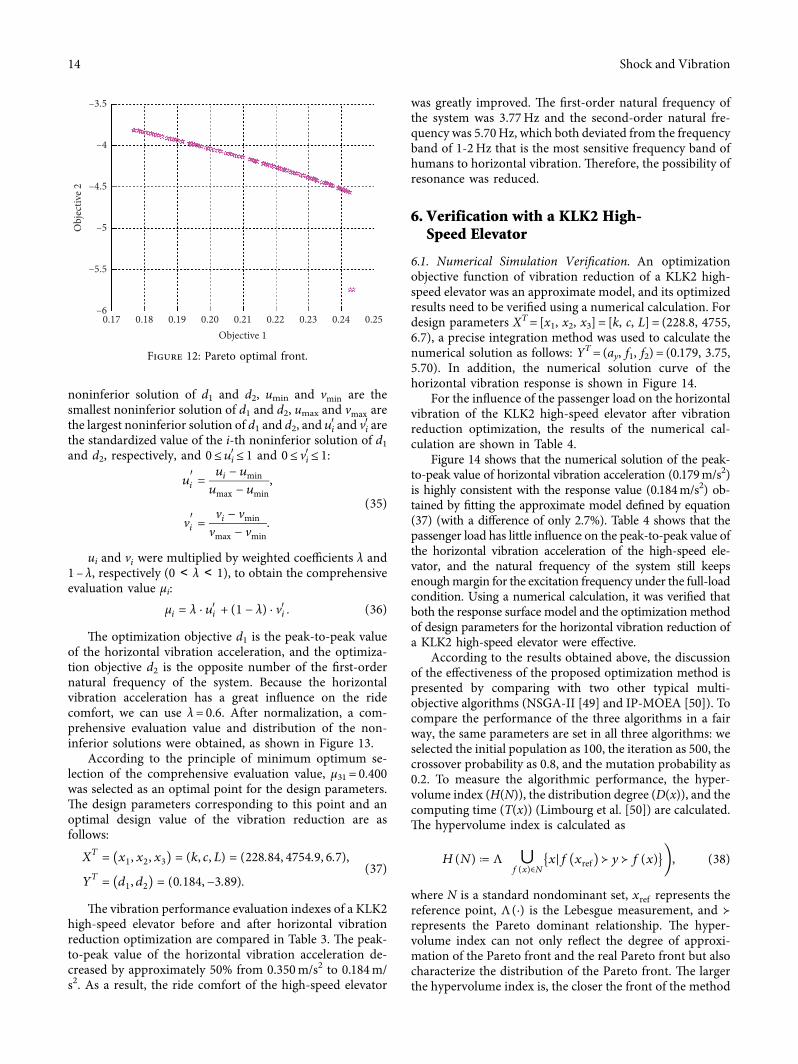