avionics - signal test iss2.pdf · avionics. alt-8015. fmcw/military pulse radio altimeter...
TRANSCRIPT
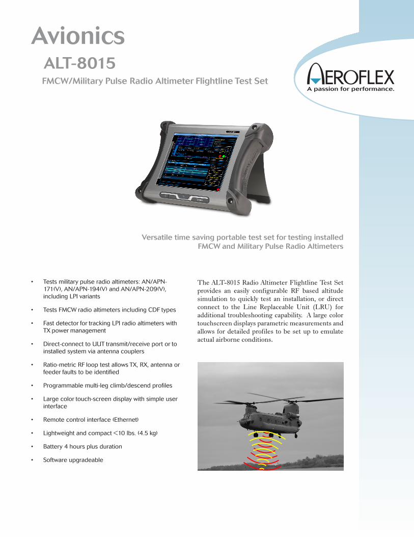
Avionics ALT-8015 FMCW/Military Pulse Radio Altimeter Flightline Test Set
Versatile time saving portable test set for testing installed FMCW and Military Pulse Radio Altimeters
• Testsmilitarypulseradioaltimeters:AN/APN-171(V),AN/APN-194(V)andAN/APN-209(V),includingLPIvariants
• TestsFMCWradioaltimetersincludingCDFtypes
• FastdetectorfortrackingLPIradioaltimeterswithTXpowermanagement
• Direct-connecttoUUTtransmit/receiveportortoinstalledsystemviaantennacouplers
• Ratio-metricRFlooptestallowsTX,RX,antennaorfeederfaultstobeidentified
• Programmablemulti-legclimb/descendprofiles
• Largecolortouch-screendisplaywithsimpleuserinterface
• Remotecontrolinterface(Ethernet)
• Lightweightandcompact<10lbs.(4.5kg)
• Battery4hoursplusduration
• Softwareupgradeable
The ALT-8015 Radio Altimeter Flightline Test Set provides an easily configurable RF based altitude simulation to quickly test an installation, or direct connect to the Line Replaceable Unit (LRU) for additional troubleshooting capability. A large color touchscreen displays parametric measurements and allows for detailed profiles to be set up to emulate actual airborne conditions.

General
The graphical user interface provides various screens for control of the test set and display of parametric measurements including.. TX power, TX frequency (center), sweep rate, TX pulse width, PRF, and link margin (pulse systems).
Simulation
RF Level may be set manually for specific receiver sensitivity measurement or auto RF Level mode sets an RF level based on TX Power – Height Path Loss – Scattering loss. This ensures that the test environment replicates the actual airborne conditions, verifying T/R loop gain and allowing antenna bonding issues (TX-RX cross leakage) to be identified. An additional level offset figure may be set to ensure an altitude sweep passes with a predetermined gain margin.
For the AN/APN-209(V) LPI variant radio altimeters, a different process is utilized. When running static altitude simulations, the link margin parameter provides a measure of receiver performance.
Simulated static altitude may be set by the user and manually incremented or decremented.
Profiles
Profiles are used to control dynamic altitude simulations. The Profile page allows the user to create, save, recall or delete named profiles. Each profile is comprised of individual legs. Start, stop altitudes and rates are definable for each leg. A profile can then be executed to simulate a complete landing approach including flare out, or a take-off and departure.
RF Coupling
The supplied antenna couplers allow the radio altitude system to be quickly verified, without access being required to test ports on the UUT LRU. Direct connection to the T/R unit is also possible.
UUT TX
UUT RX
Radio AltimeterUUT
ALT-8015Test Set
TX
RX
AircraftAntenna’s
Test SetAntennaCouplers
UUT TX
UUT RX
Radio AltimeterUUT
ALT-8015Test Set
TX
RX
AircraftAntenna’s
Test SetAntennaCouplers
Test Setup
The test setup page allows System, User and RF connection parameters to be set by the user, including, Type, UUT Detect Mode, Level Mode, Connection Type, AID, RF Cable Loss, Antenna Coupler Loss and Altitude Offset.

GENERAL SPECIFICATIONS
USER INTERFACE
Display 12” color LCD, sunlight readable w/ back light.
Controls Touch-screen
Antenna Couplers TX and RX
Coupler Loss Compensation 0 to 19.9 dB
TX/RX DIRECT CONNECTION PORTS
Impedance 50 Ω
SWR TX 2.5:1 RX 1.5:1
Connector TNC x 2 (single TX/RX channel)
RECEIVER
RF Input Frequency Range 4.20 to 4.40 GHz
FMCW/CDF FMCW Frequency Measurement Range 4.20 to 4.40 GHz Accuracy +5 MHz RF TX Power Input Tracking Range 10 mW (+10 dBm) to 2 W (+33 dBm) RF TX Power Measurement Range 4 mW (+6 dBm) to 2 W (+33 dBm) Accuracy +2 dB FM Sweep Rate Measurement Range 50 to 400 Hz Accuracy +5Hz FM Deviation Range 20 to 100 MHz Accuracy +5 MHz
Pulse Frequency Measurement Range 4.20 to 4.40 GHz Accuracy +10 MHz TX Power Measurement Range 1 mW (0 dBm) to 300 W (+54 dBm) peak Accuracy >50 ns +2 dB Accuracy <50 ns +3 dB TX Pulse Width Measurement Range 20 ns to 400 ns Accuracy +10ns TX Pulse PRF Measurement Range 0 to 30 KHz Accuracy +5%
GENERATOR
Linear Altitude Simulation Range FMCW/CDF -20 to 8,000 ft Range Pulse 50 to 8,000 ft * * Note: lower altitude limit determined by connecting RF coax cable length Resolution 1 ft Increments Accuracy +1.5ft or 2% RMS (whichever is greater)
Linear Altitude Rate: Range 1 to 120,000 fpm Resolution 1 ft increments
Test Cable (automatic compensation) Test Cable length 1 to 100 ft Test Cable Loss 0 to 9.9 dB
AID (direct connect) Fixed Selectable 0, 20, 40, 57 or 80 ft User Entered 0 to 99 ft
Offset -25 to 100 ft
RF Level Manual Mode (FM/CW) Range +9 to -84 dBm (varies with cable loss) Accuracy +4 dB
Manual Mode (Pulse) Range +17 to -76 dBm Accuracy +4 dB Auto Mode TX Power – Height Path Loss-Scattering Loss- Offset RF Level Offset (auto) -20 to +20 dB
RF Path Loss Simulation 0 to 8,000 ft
Frequency Stability +1 ppm
ENVIRONMENTAL
Test Set Certifications Operational Temperature -20° ≤ T ≤ 55° C Storage Temperature -30° ≤ T ≤ 71° C Operational Humidity MIL-PRF-28800F Class 2 Storage Humidity MIL-PRF-28800F Class 2 Altitude ≤10,000 meters Vibration Limits MIL-PRF-28800F Class 2 Shock, Functional MIL-PRF-28800F Class 2 Transit Drop MIL-PRF-28800F Class 2 Drip Proof MIL-PRF-28800F Class 2 Dust MIL-PRF-28800F Class 2 Salt MIL-PRF-28800F Class 2 Explosive Atmosphere MIL-STD-810F Method 511.4, Procedure 1 Safety Compliance UL-61010:2001, CSA 22.2 No 1010.1, WEEE, ROHS EMC Emissions MIL-PRF28800F Class 2 EN 61326:1998 Class A EN 61000-3-2 EN 61000-3-3 Immunity MIL-PRF28800F Class 2 EN 61326:1998 Class A

External AC-DC Converter Certifications Safety Compliance UL 1950 DS CSA 22.2 No. 234 VDE EN 60 950 EMI/RFI Compliance FCC Docket 20780 Curve “B” EMC EN 61326
Transit Case Certifications Drop Test FED-STD-101C Method 5007.1 Paragraph 6.3, Procedure A, Level A Falling Dart Impact ATA 300 Category I Vibration, Loose Cargo FED-STD-101C Method 5019 Vibration, Sweep ATA 300 Category I Simulated Rainfall MIL-STD-810F Method 506.4, Procedure II of 4.1.2 FED-STD-101C Method 5009.1 Sec 6.7.1 Immersion MIL-STD-810F Method 512.4
ENVIRONMENTAL
(Supplied External AC to DC Converter)
Use Indoors
Altitude ≤10,000 meters
Operating Temperature 5° to 40°C
Storage Temperature -20° to 71°C
PHYSICAL CHARACTERISTICS
Dimensions Height 10.63 inches (27.0 cm) Width 13.97 inches (35.5 cm) Depth 3.425 inches (8.7 cm) Weight (Test set only) <10 lbs. (4.5 kg)
VERSIONS AND ACCESSORIESOrder Description Number92923 ALT-8015 Radio Altimeter Test Set Standard Accessories88494 Transit case 67374 Power supply 88590 Antenna coupler (qty 2) Antenna pole assembly (qty 2)112036 Attenuator, 20dB (qty 2) 38353 TNC-TNC adapter 62401 Cable, TNC-TNC, 12” (Loop Back)64020 Power cord, European62302 Power cord, U.S.88511 Coax, RG400, TNC-TNC, yellow 20’ 89527 Coax, RG400, TNC-TNC, red 20’91253 Coax, RG400, TNC-TNC, yellow 4’ 91255 Coax, RG400, TNC-TNC, red 4’92955 Getting Started Manual92956 Operation Manual (CD)
Optional Accessories88500 Low loss RF coax cable 100 ft. (qty 2) w/ soft-side case)87040 External battery charger86196 Spare battery pack 92980 Maintenance Manual (CD)
EXPORT CONTROL:This product is controlled for export under the International Traffic in Arms Regulations (ITAR). A license from the U.S. Department of State is required prior to the export of this product from the United States.
EXPORT WARNING:Aeroflex’s military products are controlled for export under the Interna-tional Traffic in Arms Regulations (ITAR) and may not be sold or pro-posed or offered for sale to certain countries including: Belarus, Burma, China, Cuba, Haiti, Iran, Liberia, Libya, North Korea, Somalia, Syria, Sudan, and Vietnam. See ITAR 126.1 for complete information.
Ourpassionforperformanceisdefinedbythree
attributesrepresentedbythesethreeicons:
solution-minded,performance-drivenandcustomer-focused.
Part No. 46900/013, Issue 2, 02/14
Distributed By:Signal Test, Inc1529 Santiago Ridge WaySan Diego, CA 92154Tel. 1-619-575-1577 [email protected]