avr231: aes bootloader - ww1.microchip.comww1.microchip.com/downloads/en/appnotes/00002462b.pdf ·...
TRANSCRIPT

AN2462 AVR231 AES Bootloader
Introduction
This application note describes how firmware can be updated securely on AVRreg microcontrollers withbootloader capabilities The method uses the Advanced Encryption Standard (AES) to encrypt thefirmware
Figure 1 Overview
int main()
hellip
Plaintext EncryptedProgramming
AlgorithmEncrypted Plaintext
Bootloader
Features
bull Fits AVR Microcontrollers with bootloader capabilities and at least 1 KB SRAMbull Enables secure transfer of firmware and sensitive data to an AVR-based applicationbull Includes easy-to-use configurable example applications
ndash Encrypting binary files and datandash Creating target bootloadersndash Downloading encrypted files to a target
bull Implements the Advanced Encryption Standard (AES)ndash 128- 192- and 256-bit keys
bull AES Bootloader fits into 2 KBbull Typical update times of a 64 KB application 115200 baud 369 MHz target frequency
ndash AES128 27 secondsndash AES192 30 secondsndash AES256 33 seconds
bull The application can be evaluated Out Of the Box on ATmega328PB Xplained Minibull The firmware has been tested to work on the following devices with minimal or no change
ndash ATmega 8161621693264128256ndash ATmega168PAndash ATmega328PB
copy 2018 Microchip Technology Inc Application Note DS00002462B-page 1
Table of Contents
Introduction1
Features 1
1 Description4
2 Glossary 7
3 Pre-Requisites 8
4 Cryptography Overview 941 Encryption 942 Decryption 9
5 AES Overview 1051 AES Implementation1052 AES Encryption 1353 AES Decryption 1654 Key Expansion 1655 Cipher Block Chaining ndash CBC 18
6 Software Implementation and Usage 1961 Motivation 1962 Usage Overview 1963 Configuration File 2064 PC Application ndash GenTemp 2265 PC Application ndash Create 2266 PC Application ndash Update 26
7 Hardware Setup 2971 Connecting the ATmega328PB Xplained Mini Kit 2972 Programming and Debugging 30
8 AVR Bootloader 3281 Key and Header Files 3382 Project Files 3483 Atmel Studio and IAR Settings3484 Installing the Bootloader 4185 Performance 42
9 Summary 44
10 Get Source Code from Atmel | START45
11 References 46
AN2462
copy 2018 Microchip Technology Inc Application Note DS00002462B-page 2
12 Revision History47
The Microchip Web Site 48
Customer Change Notification Service48
Customer Support 48
Microchip Devices Code Protection Feature 48
Legal Notice49
Trademarks 49
Quality Management System Certified by DNV50
Worldwide Sales and Service51
AN2462
copy 2018 Microchip Technology Inc Application Note DS00002462B-page 3
1 DescriptionElectronic designs with microcontrollers always need to be equipped with firmware be it a portable musicplayer a hairdryer or a sewing machine As many electronic designs evolve rapidly there is a growingneed for being able to update products that have already been shipped or sold It may prove difficult tomake changes to hardware especially if the product has already reached the end customer but thefirmware can easily be updated on products based on Flash microcontrollers such as the AVR ManyAVR microcontrollers are configured such that it is possible to implement a bootloader able to receivefirmware updates and to reprogram the Flash memory on demand The program memory space is dividedin two sections the Bootloader Section (BLS) and the Application Section Both sections have dedicatedlock bits for read and write protection so that the bootloader code can be secured in the BLS while stillbeing able to update the code in the application area Hence the update algorithm in the BLS can easilybe secured against outside access
The problem remains with the firmware which typically is not secure before it has been programmed intoFlash memory and lock bits have been set This means that if the firmware needs to be updated in thefield it will be open for unauthorized access from the moment it leaves the programming bench ormanufacturerrsquos premises
This application note shows how data to be transferred to Flash and EEPROM memories can be securedat all times by using cryptographic methods The idea is to encrypt the data before it leaves theprogramming bench and decrypts it only after it has been downloaded to the target AVR This proceduredoes not prevent unauthorized copying of the firmware but the encrypted information is virtually uselesswithout the proper decryption keys Decryption keys are stored in only one location outside theprogramming environment - inside the AVR The keys cannot be regenerated from the encrypted dataThe only way to gain access to the data is by using the proper keys
The following figure shows an example of how a product is first manufactured loaded with initialfirmware sold and later updated with a new revision of the firmware
AN2462Description
copy 2018 Microchip Technology Inc Application Note DS00002462B-page 4
Figure 1-1 An Example of the Typical Production and Update Procedure
1
3
2
4
FIRMWARE(INITIAL)
BOOTLOADER
DECRYPTION KEYS
FIRMWARE(UPDATE)
FIRMWARE UPDATES
PRODUCT SOLDPRODUCT BEING MANUFACTURED
PRODUCT BEING UPDATED
MANUFACTURER THIRD PARTY
AVR AVR
Note 1 During manufacturing the microcontroller is first equipped with a bootloader decryption keys and
application firmware The bootloader takes care of receiving the actual application andprogramming it into Flash memory while keys are required for decrypting the incoming data Lockbits are set to secure the firmware inside the AVR
2 The product is then shipped to a distributor or sold to the end customer Lock bit settings continueto keep the firmware secured inside the AVR
3 A new release of the firmware is completed and there is a need to update products which alreadyhave been distributed The firmware is therefore encrypted and shipped to the distributor Theencrypted firmware is useless without decryption keys and therefore even local copies of thesoftware (for example on the hard drive of the distributor) do not pose a security hazard
AN2462Description
copy 2018 Microchip Technology Inc Application Note DS00002462B-page 5
4 The distributor upgrades all units in stock and those returned by customers (for example duringrepairs) The encrypted firmware is downloaded to the AVR and decrypted once inside themicrocontroller Lock bit settings continue to keep the updated firmware secured inside the AVR
AN2462Description
copy 2018 Microchip Technology Inc Application Note DS00002462B-page 6
2 GlossaryBLS Bootloader Section
EEPROM Electrically Erasable PROM
AES Advanced Encryption Standard
RAM Random Access Memory
CBC Cipher Block Chaining
PC Personal Computer
CRC Cyclic Redundancy Check
USART Universal Synchronous Asynchronous Receiver Transmitter
KB Kilobytes
LCD Liquid Crystal Display
IDE Integrated Development Environment
AN2462Glossary
copy 2018 Microchip Technology Inc Application Note DS00002462B-page 7
3 Pre-RequisitesThe solutions discussed in this document require basic familiarity with the following
bull Atmelreg Studio 7 or laterbull ATmega328PB Xplained Minibull AES conceptsbull Bootloader concepts and its implementation in AVR
This application note covers the basic overview of Advanced Encryption Standard (AES) Users who wishto have a better understanding of the concepts of AES are requested to do further reading on relevantliterature
AN2462Pre-Requisites
copy 2018 Microchip Technology Inc Application Note DS00002462B-page 8
4 Cryptography OverviewThe term cryptography is used when information is locked and made unavailable using keys Unlockinginformation can only be achieved using the correct keys
Algorithms based on cryptographic keys are divided into two classes symmetric and asymmetricSymmetric algorithms use the same key for encryption and decryption while asymmetric algorithms usedifferent keys AES is a symmetric key algorithm
41 EncryptionEncryption is the method of encoding a message or data so that its contents are hidden from outsidersThe plain-text message or data in its original form may contain information the author or distributor wantsto keep secret such as the firmware for a microcontroller For example when a microcontroller is updatedin the field it may prove difficult to secure the firmware against illicit copying attempts and reverseengineering Encrypting the firmware will render it useless until it is decrypted
42 DecryptionDecryption is the method of retrieving the original message or data and typically cannot be performedwithout knowing the proper key Keys can be stored in the bootloader of a microcontroller so that thedevice can receive encrypted data decrypt it and reprogram selected parts of the Flash or EEPROMmemory Decryption keys cannot be retrieved from the encrypted data and cannot be read from AVRmicrocontrollers if lock bits have been programmed accordingly
AN2462Cryptography Overview
copy 2018 Microchip Technology Inc Application Note DS00002462B-page 9
5 AES Overview
51 AES ImplementationThis section is not intended to be a detailed description of the AES algorithm or its history The intention israther to describe the AVR-specific implementations for the various parts of the algorithm Since memoryis a scarce resource in embedded applications the focus has been on saving code memory Thebootloader application will never be run the same time as the main code and it is therefore not importantto save data memory (RAM) as long as the data memory requirements do not exceed the capacity of themicrocontroller
In the following subsections some basic mathematical operations and their AVR-specific implementationsare described Note that there are some references to finite field theory from mathematics Knowledge offinite fields is not required to read this document but the interested reader should study the AESspecification
Note If the reader has sufficient knowledge of the implementation of AES they can skip to 6 SoftwareImplementation and Usage without loss of continuity
511 Byte AdditionIn the AES algorithm byte addition is defined as addition of individual bits without carry propagation Thisis identical to the standard XOR operation The XOR operation is its own inverse hence byte subtractionis identical to addition in the AES algorithm XOR operations are trivial to implement on AVR
512 Byte MultiplicationIn the AES algorithm byte multiplication is defined as finite field multiplication with modulus 0x11B (binary1 0001 1011) A suggested implementation is to repetitively multiply the first factor by 2 (modulo 0x11B)and sum up the intermediate results for each bit in the second factor having value 1
An example If the second factor is 0x1A (binary 0001 1010) then the first third and fourth intermediateresults should be summed
Another example is shown in the following figure This method uses little memory and is well suited for an8-bit microcontroller
AN2462AES Overview
copy 2018 Microchip Technology Inc Application Note DS00002462B-page 10
Figure 5-1 Byte MultiplicationA = 01110010 B = 00110101
A
A = 2A
A = 2A
A = 2A
A = 2A
A = 2A
A = 2A
A = 2A
1
0
0
1
1
0
1
0
=
=
=
=
=
=
=
=
01110010
0
0
11000010
01100001
0
11010011
0
00000010
Use multiplicationmodulo 0x11B
Use addition modulo 2ie XOR
The Byte Multiplication can be described by the following pseudo codebitmask = 1tempresult = 0tempfactor = firstfactorwhile bitmask lt 0x100 if bitmask AND secondfactor ltgt 0 add tempfactor to tempresult using XOR end if shift bitmask left once multiply tempfactor by 2 modulo 0x11Bend whilereturn tempresult
513 Multiplicative InversesTo be able to compute finite field multiplicative inverses that is 1x a trick has been used in thisimplementation Using exponentiation and logarithms with a common base the following identity can beutilized
Using exponentiation and logarithms to compute 1x
AN2462AES Overview
copy 2018 Microchip Technology Inc Application Note DS00002462B-page 11
In this case the base number 3 has been chosen as it is the simplest primitive root By using finite fieldmultiplication when computing the exponents and logarithms the multiplicative inverse is easy toimplement Instead of computing exponents and logarithms every time two lookup tables are used Sincethe multiplicative inverse is only used when preparing the S-box described in 514 S-Boxes the memoryused for the two lookup tables can be used for other purposes when the S-box has been prepared
The lookup table computation can be described by the following pseudo codetempexp = 0tempnum = 1do exponentiation_table[ tempexp ] = tempnum logarithm_table[ tempnum ] = tempexp increase tempexp multiply tempnum by 3 modulo 0x11Bloop while tempexp lt 256
514 S-BoxesThe AES algorithm uses the concept of substitution tables or S-boxes One of the steps of the algorithmis to apply an invertible transformation to a byte The S-box is the pre-computed results of thistransformation for all possible byte values The transformation consists of two steps (1) A multiplicativeinverse as described in 513 Multiplicative Inverses and (2) a linear transformation according to thefollowing equation where a~i~ are the bits of the result and b~i~ are the bits of the result from step 1
Linear transformation used in the S-box
A closer look at the matrix reveals that the operation can be implemented as the sum (using XORaddition) of the original byte the right-hand vector and the original byte rotated left one two three andfour times This method is well suited for an 8-bit microcontroller
The inverse S-box used for decryption has a similar structure and is also implemented using XORadditions and rotations Refer to the AES specification for the corresponding matrix and to the sourcecode for implementation details
515 The lsquoStatersquoThe AES algorithm is a block cipher which means that data is managed in blocks For the AES cipherthe block size is 16 bytes The AES block is often organized in a 4x4 array called the lsquoStatersquo or the lsquoStatearrayrsquo The leftmost column of the State holds the first four bytes of the block from top to bottom and soon The reader should also be aware that in the AES specification four consecutive bytes are referred toas a word
AN2462AES Overview
copy 2018 Microchip Technology Inc Application Note DS00002462B-page 12
52 AES EncryptionBefore discussing the steps of the encryption process the concept lsquoencryption roundrsquo needs to beintroduced Most block ciphers consist of a few operations that are executed in a loop a number of timesEach loop iteration uses a different encryption key At least one of the operations in each iterationdepends on the key The loop iterations are referred to as encryption rounds and the series of keys usedfor the rounds is called the key schedule The number of rounds depends on the key size
The flowchart for the encryption process is shown in the following figure The following subsectionsexplain the different steps in the process Each step is implemented as a subroutine for convenienceUsing an optimizing compiler removes unnecessary function calls to save code memory
Figure 5-2 Encryption Flowchart
Encrypt Block
Ready for thelast round
Add Round Key
Substitute Bytes
Shift Rows
Mix Columns
Add Round Key
No
Substitute Bytes
Shift Rows
Add Round Key
Return
Yes
521 Add Round KeyThis step uses XOR addition to add the current round key to the current State array The round key hasthe same size as the State that is 16 bytes or four words This operation is implemented as a 16-steploop
AN2462AES Overview
copy 2018 Microchip Technology Inc Application Note DS00002462B-page 13
Figure 5-3 Adding the Round Key to the Current State
S00 S01 S02 S03
S10 S11 S12 S13
S20 S21 S22 S23
S30 S31 S32 S33
S00 S01 S02 S03
S10 S11 S12 S13
S20 S21 S22 S23
S30 S31 S32 S33
S Sxor (round key )
XORkey32
522 Substitute BytesThis step uses the precalculated S-box lookup table to substitute the bytes in the State This step is alsoimplemented in a 16-step loop like the previous section
Figure 5-4 Substituting the Bytes of the Current State
S00 S01 S02 S03
S10 S11 S12 S13
S20 S21 S22 S23
S30 S31 S32 S33
S00 S01 S02 S03
S10 S11 S12 S13
S20 S21 S22 S23
S30 S31 S32 S33
S SS-box lookup
S-box[S32]
523 Shift RowsThis step operates on the rows of the current State The first row is left untouched while the last three arecycled left one two and three times respectively To cycle left once the leftmost byte is moved to therightmost column and the three remaining bytes are moved one column to the left The process is shownin the following figure
AN2462AES Overview
copy 2018 Microchip Technology Inc Application Note DS00002462B-page 14
Figure 5-5 Cycling the Rows of the Current State
S00 S01 S02 S03
S10 S11 S12 S13
S20 S21 S22 S23
S30 S31 S32 S33
S Scycle rows
0x left
1x left
2x left
3x left
S00 S01 S02 S03
S11 S12 S13 S10
S22 S23 S20 S21
S33 S30 S31 S32
The naive implementation would be to write a subroutine that cycles a row left one time and then call itthe required number of times on each row However tests show that implementing the byte shufflingdirectly without any loops or subroutines results in only a small penalty in code size but a significant gain(3x) in speed Therefore the direct implementation has been chosen Refer to the ShiftRows() functionin the source code for details
524 Mix ColumnsThis step operates on the State column by column Each column is treated as a vector of bytes and ismultiplied by a fixed matrix to get the column for the modified State
Figure 5-6 Mixing the Columns of the Current State
S00 S01 S02 S03
S10 S11 S12 S13
S20 S21 S22 S23
S30 S31 S32 S33
S00 S01 S02 S03
S10 S11 S12 S13
S20 S21 S22 S23
S30 S31 S32 S33
S SMatrix multiplication column by column
Matrix
The operation can be described by the following equation which are the bytes of the mixed column andare the bytes of the original column
Figure 5-7 Matrix Multiplication When Mixing One Column
This step is implemented directly without any secondary function calls From the matrix equation one cansee that every byte of the mixed column is a combination of the original bytes and their doubles Refer tothe MixColumns() function in the source code for details
AN2462AES Overview
copy 2018 Microchip Technology Inc Application Note DS00002462B-page 15
Note XOR Addition and Finite Field Multiplication from sections 511 Byte Addition and 512 ByteMultiplication are used
53 AES DecryptionThe process is very similar to the encryption process except the order of the steps has changed Allsteps except ldquoAdd Round Keyrdquo have their corresponding inverses ldquoInverse Shift Rowsrdquo cycles the rowsright instead of left ldquoInverse Substitute Bytesrdquo uses inverse S-boxes
ldquoInverse Mix Columnsrdquo also uses an inverse transformation Refer to the AES specification for thecorresponding matrix and to the source code for implementation details The flowchart for the decryptionprocess is shown as follows
Figure 5-8 Decryption Flowchart
Decrypt Block
Ready for thelast round
Add Round Key
Inverse Shift Rows
Inverse SubstituteBytes
Add Round Key
Inverse Mix Columns
No
Inverse Shift Rows
Inverse SubstituteBytes
Add Round Key
Return
Yes
Note The key schedule used for decryption is the same as for encryption but in reverse order
54 Key ExpansionKey expansion is the process of generating the key schedule from the original 128- 196- or 256-bitcipher key The flowchart for key expansion is shown as follows
AN2462AES Overview
copy 2018 Microchip Technology Inc Application Note DS00002462B-page 16
Figure 5-9 Key Expansion FlowchartKey Expansion
Set round constant word to 0x01 0x00 0x00 0x00
Current positionis a multiple of the key
length
Cycle temporaryword left one byte
Copy original key to startof expanded key
Copy last 4 bytes of key totemporary word
Set current position inexpanded key right after
copy of original key
Multiply roundconstant by 2
Add current roundconstant to
temporary word
Substitute each bytein temporary word
Add word from onekey length beforecurrent position totemporary word
Copy temporary word tocurrent position and
advance to next word
Reached end ofexpanded key
Return
Yes
YesCurrent position
is one block length past amultiple of the key
length
Substitute each bytein temporary word
No
Yes
No
No
Only if key size islarger than
192 bits
AN2462AES Overview
copy 2018 Microchip Technology Inc Application Note DS00002462B-page 17
The algorithm uses operations already described such as XOR addition finite field multiplicationsubstitution and word cycling Refer to the source code for details
Note The key expansion is identical for both encryption and decryption Therefore the S-box used forencryption is required even if only decryption is used In the AVR implementation the ordinary S-box iscomputed prior to key expansion and then its memory is reused when computing the inverse S-box
55 Cipher Block Chaining ndash CBCAES is a block cipher meaning that the algorithm operates on fixed-size blocks of data The cipher key isused to encrypt data in blocks of 16 bytes For a known input block and a constant (although unknown)encryption key the output block will always be the same This might provide useful information forsomebody wanting to attack the cipher system
There are some methods commonly used which cause identical plaintext blocks being encrypted todifferent ciphertext blocks One such method is called Cipher Block Chaining (CBC)
CBC is a method of connecting the cipher blocks so that leading blocks influence all trailing blocks Thisis achieved by first performing an XOR operation on the current plaintext block and the previousciphertext block The XOR result is then encrypted instead of the plaintext block This increases thenumber of plaintext bits one ciphertext bit depends on
AN2462AES Overview
copy 2018 Microchip Technology Inc Application Note DS00002462B-page 18
6 Software Implementation and UsageThis section first discusses some important topics for improving system security These topics motivatemany of the decisions in the later software design
61 MotivationThis application note presents techniques that can be used when securing a design from outside accessAlthough no design can ever be fully secured it can be constructed such that the effort required to breakthe security is as high as possible There is a significant difference between an unsecured design that aperson with basic engineering skills can duplicate and a design that only a few highly skilled intruderscan break In the unsecured case the design is easily copied and even reverse engineered violating theintellectual property of the manufacturer and jeopardizing the market potential for the design In thesecured case the effort required to break the design is so high that most intruders simply focus ondeveloping their own products
There is only one general rule on how to build a secure system It should be designed to be as difficult tobreak as possible Any mechanism that can be used to circumvent security will be tried during a breakattempt A few examples of what must be considered are given below
bull What will happen if power is removed during a firmware update What is the state of themicrocontroller when power is restored back Are lock bits and reset vectors set properly at alltimes
bull Are there any assumptions that can be made on what plain-text data will look like In order for AESto be broken there must be a pattern to look for The attack software will have to be configured tosearch for a known pattern such as interrupt vectors at the start of program memory memoryareas padded with zero or one and so on
bull Is there any feedback that can be derived from the decryption process Any such feedback canhelp the attacker For example if the decryption algorithm inside the bootloader would give an OKNot-OK type of signal for each block processed then this signal could be used as feedback to theattacker
bull Should encrypted frames be sent in another order If the first frame sent to the bootloader alwaysincludes the first block of the encrypted file then the attacker can make some assumptions fromthis For example it can be assumed that the first frame maps program data starting from addresszero and that it contains the interrupt vector table This information helps the attacker to refine thekey search To increase the security of the system send the frames in random order (the decryptedframes will be mapped to their proper address anyhow)
62 Usage OverviewThis and the following subsections describe how to use and configure the applications The process isillustrated in the following figure
AN2462Software Implementation and Usage
copy 2018 Microchip Technology Inc Application Note DS00002462B-page 19
Figure 6-1 Overview of the Project Flow
EEPROMData
Application Builder
Create
FirmwareConfigurationFile
HeaderFile Key File Encrypted
Firmware
Text editor GenTemp Miscellaneous Editor
Atmel Studio
Frames
Update
BootloaderSource
Bootloader
Target AVR
Application note
The main steps are
bull Create an application for the target AVR If required create an EEPROM layout in a separate filebull Create a configuration file with project dependent information The application called GenTemp can
be used for creating a file framebull Run the application called Create This will create the header file key file and the encrypted filebull Use Atmel Studio 7 or later configure and build the bootloader for the target AVRbull Download bootloader to target AVR and set lock and fuse bitsbull Now the encrypted firmware may be downloaded to the AVR at any time
63 Configuration FileThe configuration file contains a list of parameters which are used to configure the project Theparameters are described in the following table
Table 6-1 Summary of Configuration File Options
Parameter Description Default Required
PAGE_SIZE Size of AVR Flash page in decimal bytes Thisparameter is part dependent See the datasheet
NA Yes
KEY1 First part (128-bit) of the encryption key in hexShould be 16 random bytes with odd-parity bitsinserted after every 8th bit making a total of 18bytes
None Noencryption
No but stronglyrecommended
KEY2 Second part (64-bit) of the encryption key inhex Should be eight random bytes with odd-parity bits inserted after every 8th bit making atotal of nine bytes If omitted AES128 will beused
None UseAES128
No butrecommended
KEY3 Third part (64-bit) of the encryption key in hexShould be nine random bytes with odd-paritybits inserted after every 8th bit making a total of
None UseAES128 orAES192
No butrecommended
AN2462Software Implementation and Usage
copy 2018 Microchip Technology Inc Application Note DS00002462B-page 20
Parameter Description Default Required
nine bytes If omitted AES128 or AES192 willbe used
INITIAL_VECTOR Used for chaining cipher blocks Should be 16random bytes in hex
0 No but stronglyrecommended
SIGNATURE Frame validation data in hex This can be anyfour bytes but it is recommended that thevalues are chosen at random
0 No
ENABLE_CRC Enable CRC checking YES or NO If enabledthe whole application section will be overwrittenand the application must pass a CRC checkbefore it is allowed to start
No No butrecommended
MEM_SIZE Size of application section in target AVR (indecimal bytes)
NA Yes if CRC isused
The configuration file can be given any valid file name The name is later given as a parameter to theapplication that will create the project files Below is a sample configuration file for the ATmega328PBThe KEY1 parameter is an example 128-bit key (hex 0123456789ABCDEF0123456789ABCDEF) withparity bits insertedPAGE_SIZE = 128MEM_SIZE = 30720CRC_ENABLE = YESKEY1 = EC38ECC4C11DBC16151A5E346A872AADAD36INITIAL_VECTOR = F24D994D5DD3E9F1EEE897616C425028SIGNATURE = 89DBF334
Some of the parameters cannot be set without specific knowledge of the target AVR The following tablesummarizes the features of some present AVR microcontrollers with bootloader functionality For devicesnot present in this table refer to the data sheet of the device
Table 6-2 AVR Feature Summary
Feature M8 M16 M162 M169 M32 M64 M128 M328PB
Flash Size bytes 8192 16384 16384 16384 32768 65536 131072 32768
Flash Page sizebytes
64 128 128 128 128 256 256 128
Flash Pages 128 128 128 128 256 256 512 256
BLS (max) bytes 2048 2048 2048 2048 4096 8192 8192 4096
BLS (max) Pages 32 16 16 16 32 32 32 32
MEM_SIZE (min)bytes
6144 14336 14336 14336 28672 57344 122880 28672
PAGE_SIZE bytes 64 128 128 128 128 256 256 128
AN2462Software Implementation and Usage
copy 2018 Microchip Technology Inc Application Note DS00002462B-page 21
64 PC Application ndash GenTempThis application generates a template for the configuration file The application generates randomencryption keys and initial vectors leaving other parameters for the user to be filled in (such as the Flashpage size) It is recommended to always start with creating a template using this application
The application is used as follows
gentemp FileNameext
FileNameext is the name of the configuration file to be created After the file has been generated it canbe edited using any plain text editor
65 PC Application ndash CreateThis application reads information from the configuration file and generates key and header files for thebootloader It is also used for encrypting the firmware Typically the application is run at least twice
1 To generate key and header files for the bootloader2 When new firmware is encrypted
Note It is very important that the same encryption information (configuration file) is used whengenerating project files and encoding the firmware Otherwise the bootloader may not have the correctset of encryption keys and cannot decrypt the data It should also be noted that it is possible to use theinformation in the configuration file to decrypt the encrypted firmware Hence the configuration file mustbe kept safe at all times and should not be modified after it has been used for the first time
651 Command Line ArgumentsThe following table shows the available command line arguments
Table 6-3 Summary of Command Line Arguments
Argument Description
-c ltfilenameextgt The path to a configuration file
-d If set contents of each Flash page is deleted before writing Else previousdata will be preserved if not specifically written to
-e ltfilenameextgt The path to an EEPROM file (data that goes into EEPROM)
-f ltfilenameextgt The path to a Flash file (code that goes into Application Section)
-h ltfilenameextgt The name of the output header file This file is later included in thebootloader
-k ltfilenameextgt The name of the output key file This file is later included in the bootloader
-l [BLB12] [BLB11] [BLB02][BLB01]
Lock bits to set These lock bits are set after all data has been transferredand before control is transferred to the updated application
AN2462Software Implementation and Usage
copy 2018 Microchip Technology Inc Application Note DS00002462B-page 22
Argument Description
-n Nonsense Add a random number of nonsense records to an encryptedfile As nonsense records are ignored by the bootloader this setting doesnot affect the application only the predictability of the output file
-o ltfilenameextgt Output file name This is the encrypted file that may be distributed and sentto the target when it needs to be updated
652 First RunIn the first run typically only key and header files for the bootloader are generated The generation of keyand header files is requested using command line arguments For example
create ndashc Configtxt ndashh BootLdrh ndashk AESKeysinc
The key and header files must be copied to the project directory of the bootloader application and beincluded into the bootloader code
Note The bootloader project files are preconfigured to use the file names mentioned above that isBootLdrh and AESKeysinc It is recommended these file names are not changed
653 Subsequent RunsIn subsequent runs the application is used for encoding the firmware Prior to encryption the source filemust be compiled assembled and linked into one code segment file andor one EEPROM segment fileFiles must be of type Intelreg hex
A file name is given at the command prompt and an encrypted file will be generated according to data inthe configuration file For example
create ndashc Configtxt ndashe EEPROMhex ndashf Flashhex ndasho Updateenc ndashl BLB11 BLB12
The application software and EEPROM data files will be combined into a single encrypted file
AN2462Software Implementation and Usage
copy 2018 Microchip Technology Inc Application Note DS00002462B-page 23
654 Program FlowFigure 6-2 Flowchart of the Create Application
Create
Read config file
Command line arguments
How many keys
Use AES128
Use AES196
Use AES256
1 32
Key filename given
Create key file
Yes
Header filename given
Create header file
Yes
No
Flash filename given
Include flash filein encryption
Yes
EEPROM filename given
Include EEPROM filein encryption
Yes
No
No
Output filename given
Create encrypted file
Yes
No
No
Done
Done
Give instructions
No
Yes
655 The Encrypted FileThe Flash and EEPROM files are encrypted and stored in one target file Before encryption howeverdata is organized into records There are seven types of records as illustrated in the following figure
AN2462Software Implementation and Usage
copy 2018 Microchip Technology Inc Application Note DS00002462B-page 24
Figure 6-3 Record Types for Encrypted File
0
FLASH PAGE DATA (VARIABLE LENGTH)
2 NBAB
4 NBAB
3 NBAB
(VARIABLE LENGTH)5 NBAB
6 L R
7 R
FLASH PAGE PREPARE
END OF FRAME
FLASH PAGE PROGRAM
EEPROM SECTION DATA
LOCK BITS
RESET
RECORD TYPE LAYOUT
LEGEND
AB
LNB
R
ADDRESS IN BYTES
LOCK BITSLENGTH IN BYTES
RANDOM DATA
1 NBABFLASH PAGE ERASE
NNONSENSE
N ANY VALUE IN 8255
The record type is given as the first byte in the record The application data is broken down to recordtypes 1 2 3 and 4 (that is erase prepare load and write buffer page to Flash) The data for theEEPROM section is formatted into record type 5 Lock bits are sent in record type 6 Record types 0 and7 are for ending a frame and transmission respectively
All other records that is those with a record identifier above 7 are of type nonsense When this option isenabled (see create tool) a random number of nonsense records will be placed at random locations inthe file
The output file is created as illustrated in the following figure
Figure 6-4 Creating the Encrypted File
CHAINED AND ENCRYPTED DATA
INITIAL VECTOR
STEP 1
STEP 2
C
FZ
C
STEP 3
STEP 4
STEP 5
FRAMEFILE
CIPHER BLOCK
RECORD
CIPHER BLOCK CIPHER BLOCK CIPHER BLOCK CIPHER BLOCK
RECORDRECORDRECORD
CHAINED AND ENCRYPTED DATA
CHAINED AND ENCRYPTED DATA
The steps are described below (the numbers refer to the figure above)
AN2462Software Implementation and Usage
copy 2018 Microchip Technology Inc Application Note DS00002462B-page 25
1 Data is formatted into records which are then lined up following the frame signature (SIG) A zero(Z) is added to mark the end of the frame and the frame is padded with random data (F) to create aframe size that is a multiple of 16 bytes
2 The initial vector is attached to the frame In the first frame the vector is equal to the one given inthe configuration file In subsequent frames the initial vector is equal to the last cipher block of theprevious frame
3 The initial vector and cipher blocks are chained and encrypted The initial vector is then removedfrom the frame
4 A CRC-16 checksum (C) is calculated and added to the frame5 The length (L) of the frame excluding the length information is calculated and saved at the start of
the frame
The frame is written to the output file and the procedure is repeated until all data has been processed
66 PC Application ndash UpdateThis application is used for sending the encrypted file to the target The data can be sent via a serial porton the PC directly to the USART on the target hardware The program flow is illustrated as follows
AN2462Software Implementation and Usage
copy 2018 Microchip Technology Inc Application Note DS00002462B-page 26
Figure 6-5 Overview of the Project Flow
TwoArguments
YESNO
Update
Give Instructions
Read All File Into Buffer
Done
Done
FileExists
YESNO
Port NumberGiven
YESNO
PortInitializes
YESNO
Show Error Message
Show Error Message
Initialize Buffer Pointer
Read Size of Next Frame
Flush Input of Serial Port
Send Frame
ByteReceived
YES
NO
ByteValue
OKCRC
Retry lt 4YESNO
Show CRC Error Message Increase Retry Counter
Reset Retry Counter
Show Error Message
Close Serial Port
Close File
Pointer lt Sizeof Buffer
YESNO
Increase Pointer
Close File
The Update application reads in files generated with the Create application The file consists of one ormore concatenated frames of encrypted data The application transmits data one frame at a timepausing in between to wait for a reply from the bootloader The next frame is transmitted only after anacknowledgment has been received otherwise the application will either resend the frame or closecommunication
AN2462Software Implementation and Usage
copy 2018 Microchip Technology Inc Application Note DS00002462B-page 27
The update application is run from the command prompt The command prompt arguments are listed inthe table below
Table 6-4 Command Line Arguments for the Update Application
Argument Description
ltfilenameextgt The path to the encrypted file to be transferred
-COMn Serial port where n is the serial port number
-baudrate Baudrate where baudrate is the actual baudrate figure
For example
update blinkyext -COM1 -115200
It should be noted that the update system only updates those parts of the Flash and EEPROM denoted inthe application and EEPROM files If CRC check of the application section is enabled or the erase optionis selected in the create tool all application memory will be cleared before programming
AN2462Software Implementation and Usage
copy 2018 Microchip Technology Inc Application Note DS00002462B-page 28
7 Hardware SetupThe target hardware must be properly set up before the encrypted firmware can be sent to thebootloader In this application note it is assumed that an ATmega328PB Xplained Mini board is used forevaluation The details on configuration steps to program and debug are explained in the followingsections These sections cover only the basic information needed to get an ATmega328PB Xplained Miniup and running For more information refer to ATmega328PB Xplained Mini User Guide
71 Connecting the ATmega328PB Xplained Mini KitThis section helps the user to connect the ATmega328PB Xplained Mini with the Atmel Studio 7
1 Download and install Atmel Studio version 7 or later versions2 Launch the Atmel Studio3 Connect the ATmega328PB Xplained Mini to the USB port and it will be visible in the Atmel Studio
711 Auto Board Identification of Xplained Mini Kitbull Once the ATmega328PB Xplained Mini kit is connected to the PC the Windowsreg Task bar will pop-
up a message as shown belowFigure 7-1 ATmega328PB Xplained Mini Driver Installation
bull If the driver installation is proper EDBG will be listed in the Device Manager as shown below
AN2462Hardware Setup
copy 2018 Microchip Technology Inc Application Note DS00002462B-page 29
Figure 7-2 Successful mEDBG Driver Installation
bull Open Atmel Studio and go to View rarr Available Tools The EDBG should get listed in the tools asmEDBG and the tool status should display as Connected This indicates that the tool iscommunicating properly with Atmel Studio
Figure 7-3 mEDBG under Available Tools
712 Connect the ATmega328PB Xplained Mini UART to the mEDBG COM Port1 Connect the mEDBG USB to the PC2 Use the Device Manager to find the COM port number3 Default COM port settings are 9600 baud N 8 1 The COM port settings can be changed according
to the application by using the Device Manager This application has been tested with a baud rateof 115200
72 Programming and DebuggingThis section helps to program and debug the ATmega328PB Xplained Mini kit by using mEDBG
721 Programming the ATmega328PB Xplained Mini By Using mEDBG1 Connect the mEDBG USB to the PC2 Go to the Atmel Studio Click Tools select Device Programming and then select the connected
mEDBG as Tool with Device as ATmega328PB and Interface as ISP click Apply
AN2462Hardware Setup
copy 2018 Microchip Technology Inc Application Note DS00002462B-page 30
3 Select Memories and locate the source hex or elf file and then click Program4 If the source contains fuse settings go to Production file and upload the elf file and program the
fuses
Note If ISP programming fails it could be because the debugWIRE is enabled See 722 Debuggingthe ATmega328PB Xplained Mini By Using mEDBG on how to disable debugWIRE mode
722 Debugging the ATmega328PB Xplained Mini By Using mEDBG1 Start Atmel Studio2 Connect the mEDBG USB to the PC3 Open your project4 In the Project menu select the project properties page Select the Tools tab and select mEDBG
as debugger and debugWIRE as the interface5 In the Debug menu click Start Debugging and Break6 Atmel Studio will display an error message if the DWEN fuse in the ATmega328PB is not enabled
click YES to make Studio set the fuse using the ISP interface7 A debug session is started with a break in main Debugging can start8 When exiting debug mode select Disable debugWIRE and Close in the Debug menu This will
disable the DWEN fuse
Note 1 If the debug mode is not exited by selecting Disable debugWIRE and Close in the Debug menu
the DWEN fuse will be enabled and the target will still be in debug mode ie it will not be possibleto program the target by using the SPI (ISP) interface
2 The bootloader code supplied with this application note has been optimized for size and hence itmay not be possible to do debugging Removing the optimization will increase the code size and itmay not fit into the bootloader section Hence it is recommended to use only the programmingmode
AN2462Hardware Setup
copy 2018 Microchip Technology Inc Application Note DS00002462B-page 31
8 AVR BootloaderThe bootloader must reside in the target AVR before the device can be updated with encrypted firmwareThe bootloader communicates with the PC and is capable of programming the EEPROM and theapplication area of the Flash memory The bootloader included with this application note has beencreated by using Atmel Studio 7 The program flow is illustrated in the figure below
AN2462AVR Bootloader
copy 2018 Microchip Technology Inc Application Note DS00002462B-page 32
Figure 8-1 Flowchart for the AVR Bootloader
Switch SW7Pressed
YESNO
Bootldr
Load Initial Vector for CBC
Calculate CRC of Appl Section
ApplicationCRC Valid
YES
NO
Read Frame Size (Two Characters)
Read Character Store in RAM
Update Frame CRC Counter
Jump to Application
End ofFrame
YES
NO
Frame CRCValid
YES NO
Decrypt and Unchain Send Frame CRC Error
SignatureValid
YES NO
Ignore Frame BUT Send OKType
LoadData
WritePage
WriteEEPROM
WriteLock Bits
Set InitialVector
PreparePage
Send OK
PREPARE DATA PROGRAM EEPROM LOCKBITS RESET EOF
NOTE WELL IF CRC IS VALID FRAME ISDECRYPTED ANY INFORMATION SENTON DECRYPTION STATUS OTHER THANOK MAY BE USED IN AN ATTACK ATTEMPT
ErasePage
ERASE
CRC CheckEnabled
YES
NO
DoNothing
NONSENSE
81 Key and Header FilesBefore the bootloader can be compiled there are some parameters that need to be set up To start withthe encryption key and target header files generated by the PC application create must be copied to the
AN2462AVR Bootloader
copy 2018 Microchip Technology Inc Application Note DS00002462B-page 33
bootloader directory The files will be included when they are referred to with the include directive insidethe bootloader source code
82 Project FilesThe application note comes with device-specific project files for ATmega328PB
For other AVR devices use the project file and modify them as per the steps given in the followingsection
83 Atmel Studio and IAR SettingsThe common settings for Atmel Studio and IARtrade will be listed in this section
1 The essential fuse settings11 The boot reset vector must be enabled12 Set Low Fuse Byte to use External Clock 16 MHz to make the ATmega328PB example
(BAUD RATE 38400) download from Atmel START work properly2 The SPMCSR register address has to be defined using SPMREG (refer to the table below) macro
in regh file this register address will change if the register is located in the indirect memory regionthe address of this register can be found in the register summary section of the data sheetFigure 8-2 Setting SPMREG Address in regh
3 Other register addresses defined in regh file have to be modified according to the device datasheet
AN2462AVR Bootloader
copy 2018 Microchip Technology Inc Application Note DS00002462B-page 34
4 Symbol __RAMPZ__ (refer to the table below) has to be defined in compiler and assembler for thedevices with flash size greater than 64 KB
5 Symbol __MEMSPM__ (refer to the table below) has to be defined in assembler for the deviceswhose SPMCSR register is located above the direct memory access region (ie if SPMCSRregister is located above 0x3F) For eg ATmega128 has SPMCSR located at 0x68 and hence thedefinition is required for accessing it
6 Symbol BOOT_ADDR=ltbootloader section start addressgt (refer to the table below) has to bedefined in the compiler for the devices with flash size greater than 64 KB
Table 8-1 Summary of Symbol Settings
Setting M8 M16 M32 M64 M128 M256 M162 M169 M328PB M168PA
__RAMPZ__ No No No No Yes Yes No No No No
__MEMSPM__ No No No No Yes No No No No No
BOOT_ADDR No No No No 0x1E000 0x3E000 No No No No
BOOT_START(IAR) 0x1800 0x3800 0x7000 0xE000 0x1E000 0x3E000 0x3800 0x3800 0x7000 0x3800
text(Atmel Studio) 0x1800 0x3800 0x7000 0xE000 0x1E000 0x3E000 0x3800 0x3800 0x7000 0x3800
SPMREG 0x37 0x37 0x37 0x37 0x68 0x37 0x37 0x37 0x37 0x37
Note The value of BOOT_ADDRBOOT_START and text in the table above is the value when the bootsize is maximum You can change this value according to the actual boot size
831 Atmel Studio SettingsThe compiler linker and assembler setting shown below are required while configuring for a specificdevice in Atmel Studio
1 Bootloader start address text (refer to Table 8-1) has to be defined in the linker setting for linkingthe code to the bootloader start address (as shown in the figure below) Start address should begiven as byte address (multiplying word address by 2) For eg if bootloader word address ofATmega328PB is 0x3C00 corresponding byte would be 0x3C00 2 = 0x7800
AN2462AVR Bootloader
copy 2018 Microchip Technology Inc Application Note DS00002462B-page 35
Figure 8-3 Setting Bootloader Address Code Link Address
2 Optimization Settings (as shown in the figure below)Figure 8-4 Optimization Settings
3 Other Linker Settings (as shown in the figure below)
AN2462AVR Bootloader
copy 2018 Microchip Technology Inc Application Note DS00002462B-page 36
Figure 8-5 Other Linker Settings
832 IAR SettingsThe compiler linker and assembler settings shown below are required while configuring for a specificdevice in IAR
1 When using the mEDBG in the ATmega328PB Xplained Mini kit the Atmel-ICE should be selectedin Debugger Driver setting (as shown in the figure below)
AN2462AVR Bootloader
copy 2018 Microchip Technology Inc Application Note DS00002462B-page 37
Figure 8-6 Debugger Driver
2 A user-defined xcl file should be used to override default linker file Follow the steps below to makethe linker work properly21 Copy the template linker file (for example CProgram Files (x86)IAR SystemsEmbedded
Workbench 74avrsrctemplatecfgm328pbxcl) according to the device to your project andrename it what you like
22 Open this file and paste the below content under the original content and save it-ca90-w29
============================================================================= Interrupt vectors
-Z(CODE)INTVEC=BOOT_START-(BOOT_START+_X_INTVEC_SIZE-1)-H1895 -h(CODE)BOOT_START-(BOOT_START+_X_INTVEC_SIZE-1)
============================================================================= Code memory
-Z(CODE)NEAR_FHUGE_FSWITCHINITTABDIFUNCTCODE=BOOT_START-_X_FLASH_END-Z(FARCODE)FAR_FFARCODE=BOOT_START-_X_FLASH_END
============================================================================= RAM
AN2462AVR Bootloader
copy 2018 Microchip Technology Inc Application Note DS00002462B-page 38
-Z(DATA)NEAR_INEAR_Z=_X_SRAM_BASE-_X_SRAM_END-Z(DATA)RSTACK+_X_RSTACK_SIZE=(_X_SRAM_END-_X_RSTACK_SIZE+1)-_X_SRAM_END-Z(DATA)CSTACK+_X_CSTACK_SIZE=(_X_SRAM_END-_X_RSTACK_SIZE-_X_CSTACK_SIZE+1)-(_X_SRAM_END-_X_RSTACK_SIZE)-Z(DATA)RSTACK+40=(_X_SRAM_END-40+1)-_X_SRAM_END-Z(DATA)CSTACK+300=(_X_SRAM_END-40-300+1)-(_X_SRAM_END-40)-Z(DATA)TINY_ITINY_ZTINY_N=RAM_BASE-FF-Z(DATA)TINY_ITINY_ZTINY_N=RAM_BASE-100
23 Use this file to override the default linker file (as shown in the figure below)Figure 8-7 Override Default Linker File
24 Define BOOT_START (refer to Table 8-1) according to the device (as shown in the figurebelow)
AN2462AVR Bootloader
copy 2018 Microchip Technology Inc Application Note DS00002462B-page 39
Figure 8-8 Linker define
3 Optimization Settings (as shown in the figure below)
AN2462AVR Bootloader
copy 2018 Microchip Technology Inc Application Note DS00002462B-page 40
Figure 8-9 Optimization Settings
84 Installing the BootloaderCompile the bootloader and then download it to the target using Atmel Studio 7 or later Before runningthe bootloader the following fuse bits must be configured
bull Size of Boot Loader Section Set fuse bits so that the section size matches the BOOT_SIZE settingas described earlier Note that the BLS is usually given in words but the BOOT_SIZE parameter isgiven in bytes
bull Boot reset vector The boot reset vector must be enabledbull Oscillator options The oscillator fuse bits are device dependent They may require configuration
(affects USART)
Note Pay special attention in setting oscillator options correctly Even a small misadjustment couldresult in communication failure
Recommended fuse bit settings are provided in the table below See the device data sheet for detailedexplanation of device dependent fuse bits
AN2462AVR Bootloader
copy 2018 Microchip Technology Inc Application Note DS00002462B-page 41
Table 8-2 Recommended Fuse Bits
M8 M8515 M8535M16 M162 M169 M32M64
M128 328PB
BOOTSZ10 00 01 01
BOOTRST 0 0 0
Note ldquo0rdquo means programmed ldquo1rdquo means not programmed
It is recommended to program lock bits to protect both the application memory and the bootloader butonly after fuse bits have been set Lock bits can be programmed using Microchip IDE (Atmel Studio 7 orlater) BLS lock bits will also be set during firmware update provided that they have been defined ascommand line arguments when the firmware is encrypted The recommended lock bit settings are
bull Memory lock bits These should be set to prevent unauthorized access to memory Note that afterthe memory has been locked it cannot be accessed via in-system programming without erasing thedevice
bull Protection mode for Boot Loader Section SPM and LPM should not be allowed to write to or readfrom the BLS This will prevent the firmware in the application section to corrupt the bootloader andwill keep the decryption keys safe
bull Protection mode for application section No restrictions should be set for SPM or LPM accessingthe application section otherwise the bootloader cannot program it
Note It is important to understand that if the device is not properly locked then the memory can beaccessed via an ISP interface and the whole point of encrypting the firmware is gone
Recommended lock bit setting for present AVR MCUs are given in the table below See the device datasheet for a detailed explanation of lock bits
Table 8-3 Recommended Lock Bits
M8 M8515 M8535 M16
M162 M169 M32 M64 M128
328PB
BLB12 BLB11 0 0 0 0
BLB02 BLB01 1 1 1 1
LB2 LB1 0 0 0 0
85 PerformanceThe following sections summarize the system performance with respect to execution time and code size
851 Execution TimeThe time required for the target device to receive decode and program data depends on the followingfactors
bull File size The more data the longer it takesbull Baudrate The higher the transmission speed the shorter the transmission timebull Target AVR speed The higher the clock frequency the shorter the decoding time
AN2462AVR Bootloader
copy 2018 Microchip Technology Inc Application Note DS00002462B-page 42
bull Programming time of Flash page This is a device constant and cannot be alteredbull Key-size AES128 is faster to decrypt than AES256 In fact AES192 is slower than AES256 It has
something to do with 192 not being a power of 2bull Miscellaneous settings For example CRC check of application section takes short time
852 Code SizeUsing the highest optimization setting for the compiler the bootloader will fit nicely into 2 KB of Flashmemory
It should be noted that if no encryption keys are given the bootloader is built without AES support Thisapplication note then performs as a standard bootloader system and can be used on any AVR withbootloader support
AN2462AVR Bootloader
copy 2018 Microchip Technology Inc Application Note DS00002462B-page 43
9 SummaryThis application note has presented a method for transferring data securely to an AVR microcontrollerwith bootloader capabilities This document has also highlighted techniques that should be implementedwhen building a secured system The following issues should be considered in order to increase thesecurity of an AVR design
Implement a bootloader that supports downloading in encrypted form When the bootloader is firstinstalled (during manufacturing) it must be equipped with decryption keys required for future firmwareupdates The firmware can then be distributed in an encrypted form securing the contents from outsiders
Use AVR lock bits to secure Application and Boot Loader sections When lock bits are set to preventreading from the device the memory contents cannot be retrieved If lock bits are not set there is no useencrypting the firmware
Encrypt the firmware before distribution Encrypted software is worthless to any outside the entity withoutthe proper decryption keys
Keep encryption keys safe Encryption keys should be stored in two places only in the bootloader whichhas been secured by lock bits and in the firmware development bench at the manufacturer
Chain encrypt data When data is chained each encrypted block depends on the previous block As aconsequence equal plaintext blocks produce different encrypted outputs
Avoid standard predictable patterns in the firmware Most programs have a common framework and anypredictable patterns such as an interrupt vector table starting with a jump to a low address only serve tohelp the intruder Also avoid padding unused memory areas with a constant number
Hide the method There is no need to mention which algorithm is being used or what the key length isThe less the intruder knows about the system the better It may be argued that knowing the encryptionmethod fends off some attackers but knowing nothing about the method increases the effort and mayfend off even more
The bootloader may also be used to erase the application section if required Many attack attemptsinclude removing the device from its normal working environment and powering it up in a hacking benchDetecting for example that an LCD is missing or that there are CRC errors in the memory thebootloader may initiate a complete erase of all memory (including the bootloader section and decryptionkeys)
In applications where it is not feasible or possible to use an external communications channel forupdates the firmware can be stored in one of the CryptoMemoryreg devices The memory can bepackaged as a removable smart card which can easily be inserted in a slot of the device when anupgrade is needed The microcontroller can check for the presence of a CryptoMemory upon start-up andretrieve a firmware upgrade as needed
Use secure hardware A strong encryption protocol is useless if the hardware has structural flaws Thereare no reported security issues with the AVR microcontrollers
This list can be made much longer but the purpose of it is merely to set the designer off in the rightdirection Do not underestimate the wit or endurance of your opponent
AN2462Summary
copy 2018 Microchip Technology Inc Application Note DS00002462B-page 44
10 Get Source Code from Atmel | STARTThe example code is available through Atmel | START which is a web-based tool that enablesconfiguration of application code through a Graphical User Interface (GUI) The code can be downloadedfor both Atmel Studio and IAR Embedded Workbenchreg via the direct example code-link(s) below or theBROWSE EXAMPLES button on the Atmel | START front page
Atmel | START web page httpstartatmelcom
Example Code
bull AVR231 AES Bootloaderndash httpstartatmelcomexampleAtmelAVR231_AES_Bootloader
001ApplicationAVR231_AES_Bootloader
Press User guide in Atmel | START for details and information about example projects The User guidebutton can be found in the example browser and by clicking the project name in the dashboard viewwithin the Atmel | START project configurator
Atmel Studio
Download the code as an atzip file for Atmel Studio from the example browser in Atmel | START byclicking DOWNLOAD SELECTED EXAMPLE To download the file from within Atmel | START clickEXPORT PROJECT followed by DOWNLOAD PACK
Double-click the downloaded atzip file and the project will be imported to Atmel Studio 70
IAR Embedded Workbench
For information on how to import the project in IAR Embedded Workbench open the Atmel | START userguide select Using Atmel Start Output in External Tools and IAR Embedded Workbench A link to theAtmel | START user guide can be found by clicking About from the Atmel | START front page or Help AndSupport within the project configurator both located in the upper right corner of the page
AN2462Get Source Code from Atmel | START
copy 2018 Microchip Technology Inc Application Note DS00002462B-page 45
11 Referencesbull ATmega328PB data sheet (httpwwwmicrochipcomwwwproductsenatmega328pb)bull ATmega328PB Xplained Mini kit (httpwwwmicrochipcomdevelopmenttoolsproductdetailsaspx
partno=atmega328pb-xmini)bull Atmel Studio (httpwwwatmelcomtoolsatmelstudioaspxtab=overview)bull Atmel START (httpstartatmelcom)bull AT10764 (httpww1microchipcomdownloadsenappnotesatmel-42508-software-library-for-
aes-128-encryption-and-decryption_applicationnote_at10764pdf)bull AVR230 DES Bootloader (httpww1microchipcomdownloadsenappnotesdoc2541pdf )bull Handbook of Applied Cryptography (httpcacruwaterloocahac)bull AES Specification (httpcsrcnistgovpublicationsfipsfips197fips-197pdf)
AN2462References
copy 2018 Microchip Technology Inc Application Note DS00002462B-page 46
12 Revision HistoryDoc Rev Date Comments
B 042018 Section Get Source Code from Atmel START is added with the link to AtmelSTART example code
A 062017 Converted to Microchip format and replaced the Atmel document number 2589The document is updated and the application code is tested for the ATmega328PBdevice
2589E 032012 New templateSection PC Application is updated
Fixed wrong interrupt vector size in the ATmega32 project
Removed cycle dependance on data
2589D 082006 Some minor fixes
AN2462Revision History
copy 2018 Microchip Technology Inc Application Note DS00002462B-page 47
The Microchip Web Site
Microchip provides online support via our web site at httpwwwmicrochipcom This web site is used asa means to make files and information easily available to customers Accessible by using your favoriteInternet browser the web site contains the following information
bull Product Support ndash Data sheets and errata application notes and sample programs designresources userrsquos guides and hardware support documents latest software releases and archivedsoftware
bull General Technical Support ndash Frequently Asked Questions (FAQ) technical support requestsonline discussion groups Microchip consultant program member listing
bull Business of Microchip ndash Product selector and ordering guides latest Microchip press releaseslisting of seminars and events listings of Microchip sales offices distributors and factoryrepresentatives
Customer Change Notification Service
Microchiprsquos customer notification service helps keep customers current on Microchip productsSubscribers will receive e-mail notification whenever there are changes updates revisions or erratarelated to a specified product family or development tool of interest
To register access the Microchip web site at httpwwwmicrochipcom Under ldquoSupportrdquo click onldquoCustomer Change Notificationrdquo and follow the registration instructions
Customer Support
Users of Microchip products can receive assistance through several channels
bull Distributor or Representativebull Local Sales Officebull Field Application Engineer (FAE)bull Technical Support
Customers should contact their distributor representative or Field Application Engineer (FAE) for supportLocal sales offices are also available to help customers A listing of sales offices and locations is includedin the back of this document
Technical support is available through the web site at httpwwwmicrochipcomsupport
Microchip Devices Code Protection Feature
Note the following details of the code protection feature on Microchip devices
bull Microchip products meet the specification contained in their particular Microchip Data Sheetbull Microchip believes that its family of products is one of the most secure families of its kind on the
market today when used in the intended manner and under normal conditionsbull There are dishonest and possibly illegal methods used to breach the code protection feature All of
these methods to our knowledge require using the Microchip products in a manner outside theoperating specifications contained in Microchiprsquos Data Sheets Most likely the person doing so isengaged in theft of intellectual property
bull Microchip is willing to work with the customer who is concerned about the integrity of their code
AN2462
copy 2018 Microchip Technology Inc Application Note DS00002462B-page 48
bull Neither Microchip nor any other semiconductor manufacturer can guarantee the security of theircode Code protection does not mean that we are guaranteeing the product as ldquounbreakablerdquo
Code protection is constantly evolving We at Microchip are committed to continuously improving thecode protection features of our products Attempts to break Microchiprsquos code protection feature may be aviolation of the Digital Millennium Copyright Act If such acts allow unauthorized access to your softwareor other copyrighted work you may have a right to sue for relief under that Act
Legal Notice
Information contained in this publication regarding device applications and the like is provided only foryour convenience and may be superseded by updates It is your responsibility to ensure that yourapplication meets with your specifications MICROCHIP MAKES NO REPRESENTATIONS ORWARRANTIES OF ANY KIND WHETHER EXPRESS OR IMPLIED WRITTEN OR ORAL STATUTORYOR OTHERWISE RELATED TO THE INFORMATION INCLUDING BUT NOT LIMITED TO ITSCONDITION QUALITY PERFORMANCE MERCHANTABILITY OR FITNESS FOR PURPOSEMicrochip disclaims all liability arising from this information and its use Use of Microchip devices in lifesupport andor safety applications is entirely at the buyerrsquos risk and the buyer agrees to defendindemnify and hold harmless Microchip from any and all damages claims suits or expenses resultingfrom such use No licenses are conveyed implicitly or otherwise under any Microchip intellectualproperty rights unless otherwise stated
Trademarks
The Microchip name and logo the Microchip logo AnyRate AVR AVR logo AVR Freaks BeaconThingsBitCloud CryptoMemory CryptoRF dsPIC FlashFlex flexPWR Heldo JukeBlox KeeLoq KeeLoq logoKleer LANCheck LINK MD maXStylus maXTouch MediaLB megaAVR MOST MOST logo MPLABOptoLyzer PIC picoPower PICSTART PIC32 logo Prochip Designer QTouch RightTouch SAM-BASpyNIC SST SST Logo SuperFlash tinyAVR UNIO and XMEGA are registered trademarks ofMicrochip Technology Incorporated in the USA and other countries
ClockWorks The Embedded Control Solutions Company EtherSynch Hyper Speed Control HyperLightLoad IntelliMOS mTouch Precision Edge and Quiet-Wire are registered trademarks of MicrochipTechnology Incorporated in the USA
Adjacent Key Suppression AKS Analog-for-the-Digital Age Any Capacitor AnyIn AnyOut BodyComchipKIT chipKIT logo CodeGuard CryptoAuthentication CryptoCompanion CryptoControllerdsPICDEM dsPICDEMnet Dynamic Average Matching DAM ECAN EtherGREEN In-Circuit SerialProgramming ICSP Inter-Chip Connectivity JitterBlocker KleerNet KleerNet logo Mindi MiWimotorBench MPASM MPF MPLAB Certified logo MPLIB MPLINK MultiTRAK NetDetach OmniscientCode Generation PICDEM PICDEMnet PICkit PICtail PureSilicon QMatrix RightTouch logo REALICE Ripple Blocker SAM-ICE Serial Quad IO SMART-IS SQI SuperSwitcher SuperSwitcher II TotalEndurance TSHARC USBCheck VariSense ViewSpan WiperLock Wireless DNA and ZENA aretrademarks of Microchip Technology Incorporated in the USA and other countries
SQTP is a service mark of Microchip Technology Incorporated in the USA
Silicon Storage Technology is a registered trademark of Microchip Technology Inc in other countries
GestIC is a registered trademark of Microchip Technology Germany II GmbH amp Co KG a subsidiary ofMicrochip Technology Inc in other countries
All other trademarks mentioned herein are property of their respective companies
AN2462
copy 2018 Microchip Technology Inc Application Note DS00002462B-page 49
copy 2018 Microchip Technology Incorporated Printed in the USA All Rights Reserved
ISBN 978-1-5224-2831-2
Quality Management System Certified by DNV
ISOTS 16949Microchip received ISOTS-169492009 certification for its worldwide headquarters design and waferfabrication facilities in Chandler and Tempe Arizona Gresham Oregon and design centers in Californiaand India The Companyrsquos quality system processes and procedures are for its PICreg MCUs and dsPICreg
DSCs KEELOQreg code hopping devices Serial EEPROMs microperipherals nonvolatile memory andanalog products In addition Microchiprsquos quality system for the design and manufacture of developmentsystems is ISO 90012000 certified
AN2462
copy 2018 Microchip Technology Inc Application Note DS00002462B-page 50
AMERICAS ASIAPACIFIC ASIAPACIFIC EUROPECorporate Office2355 West Chandler BlvdChandler AZ 85224-6199Tel 480-792-7200Fax 480-792-7277Technical SupporthttpwwwmicrochipcomsupportWeb AddresswwwmicrochipcomAtlantaDuluth GATel 678-957-9614Fax 678-957-1455Austin TXTel 512-257-3370BostonWestborough MATel 774-760-0087Fax 774-760-0088ChicagoItasca ILTel 630-285-0071Fax 630-285-0075DallasAddison TXTel 972-818-7423Fax 972-818-2924DetroitNovi MITel 248-848-4000Houston TXTel 281-894-5983IndianapolisNoblesville INTel 317-773-8323Fax 317-773-5453Tel 317-536-2380Los AngelesMission Viejo CATel 949-462-9523Fax 949-462-9608Tel 951-273-7800Raleigh NCTel 919-844-7510New York NYTel 631-435-6000San Jose CATel 408-735-9110Tel 408-436-4270Canada - TorontoTel 905-695-1980Fax 905-695-2078
Australia - SydneyTel 61-2-9868-6733China - BeijingTel 86-10-8569-7000China - ChengduTel 86-28-8665-5511China - ChongqingTel 86-23-8980-9588China - DongguanTel 86-769-8702-9880China - GuangzhouTel 86-20-8755-8029China - HangzhouTel 86-571-8792-8115China - Hong Kong SARTel 852-2943-5100China - NanjingTel 86-25-8473-2460China - QingdaoTel 86-532-8502-7355China - ShanghaiTel 86-21-3326-8000China - ShenyangTel 86-24-2334-2829China - ShenzhenTel 86-755-8864-2200China - SuzhouTel 86-186-6233-1526China - WuhanTel 86-27-5980-5300China - XianTel 86-29-8833-7252China - XiamenTel 86-592-2388138China - ZhuhaiTel 86-756-3210040
India - BangaloreTel 91-80-3090-4444India - New DelhiTel 91-11-4160-8631India - PuneTel 91-20-4121-0141Japan - OsakaTel 81-6-6152-7160Japan - TokyoTel 81-3-6880- 3770Korea - DaeguTel 82-53-744-4301Korea - SeoulTel 82-2-554-7200Malaysia - Kuala LumpurTel 60-3-7651-7906Malaysia - PenangTel 60-4-227-8870Philippines - ManilaTel 63-2-634-9065SingaporeTel 65-6334-8870Taiwan - Hsin ChuTel 886-3-577-8366Taiwan - KaohsiungTel 886-7-213-7830Taiwan - TaipeiTel 886-2-2508-8600Thailand - BangkokTel 66-2-694-1351Vietnam - Ho Chi MinhTel 84-28-5448-2100
Austria - WelsTel 43-7242-2244-39Fax 43-7242-2244-393Denmark - CopenhagenTel 45-4450-2828Fax 45-4485-2829Finland - EspooTel 358-9-4520-820France - ParisTel 33-1-69-53-63-20Fax 33-1-69-30-90-79Germany - GarchingTel 49-8931-9700Germany - HaanTel 49-2129-3766400Germany - HeilbronnTel 49-7131-67-3636Germany - KarlsruheTel 49-721-625370Germany - MunichTel 49-89-627-144-0Fax 49-89-627-144-44Germany - RosenheimTel 49-8031-354-560Israel - RarsquoananaTel 972-9-744-7705Italy - MilanTel 39-0331-742611Fax 39-0331-466781Italy - PadovaTel 39-049-7625286Netherlands - DrunenTel 31-416-690399Fax 31-416-690340Norway - TrondheimTel 47-7289-7561Poland - WarsawTel 48-22-3325737Romania - BucharestTel 40-21-407-87-50Spain - MadridTel 34-91-708-08-90Fax 34-91-708-08-91Sweden - GothenbergTel 46-31-704-60-40Sweden - StockholmTel 46-8-5090-4654UK - WokinghamTel 44-118-921-5800Fax 44-118-921-5820
Worldwide Sales and Service
copy 2018 Microchip Technology Inc Application Note DS00002462B-page 51
- Introduction
- Features
- Table of Contents
- 1 Description
- 2 Glossary
- 3 Pre-Requisites
- 4 Cryptography Overview
-
- 41 Encryption
- 42 Decryption
-
- 5 AES Overview
-
- 51 AES Implementation
-
- 511 Byte Addition
- 512 Byte Multiplication
- 513 Multiplicative Inverses
- 514 S-Boxes
- 515 The lsquoStatersquo
-
- 52 AES Encryption
-
- 521 Add Round Key
- 522 Substitute Bytes
- 523 Shift Rows
- 524 Mix Columns
-
- 53 AES Decryption
- 54 Key Expansion
- 55 Cipher Block Chaining ndash CBC
-
- 6 Software Implementation and Usage
-
- 61 Motivation
- 62 Usage Overview
- 63 Configuration File
- 64 PC Application ndash GenTemp
- 65 PC Application ndash Create
-
- 651 Command Line Arguments
- 652 First Run
- 653 Subsequent Runs
- 654 Program Flow
- 655 The Encrypted File
-
- 66 PC Application ndash Update
-
- 7 Hardware Setup
-
- 71 Connecting the ATmega328PB Xplained Mini Kit
-
- 711 Auto Board Identification of Xplained Mini Kit
- 712 Connect the ATmega328PB Xplained Mini UART to the mEDBG COM Port
-
- 72 Programming and Debugging
-
- 721 Programming the ATmega328PB Xplained Mini By Using mEDBG
- 722 Debugging the ATmega328PB Xplained Mini By Using mEDBG
-
- 8 AVR Bootloader
-
- 81 Key and Header Files
- 82 Project Files
- 83 Atmel Studio and IAR Settings
-
- 831 Atmel Studio Settings
- 832 IAR Settings
-
- 84 Installing the Bootloader
- 85 Performance
-
- 851 Execution Time
- 852 Code Size
-
- 9 Summary
- 10 Get Source Code from Atmel | START
- 11 References
- 12 Revision History
- The Microchip Web Site
- Customer Change Notification Service
- Customer Support
- Microchip Devices Code Protection Feature
- Legal Notice
- Trademarks
- Quality Management System Certified by DNV
- Worldwide Sales and Service
-
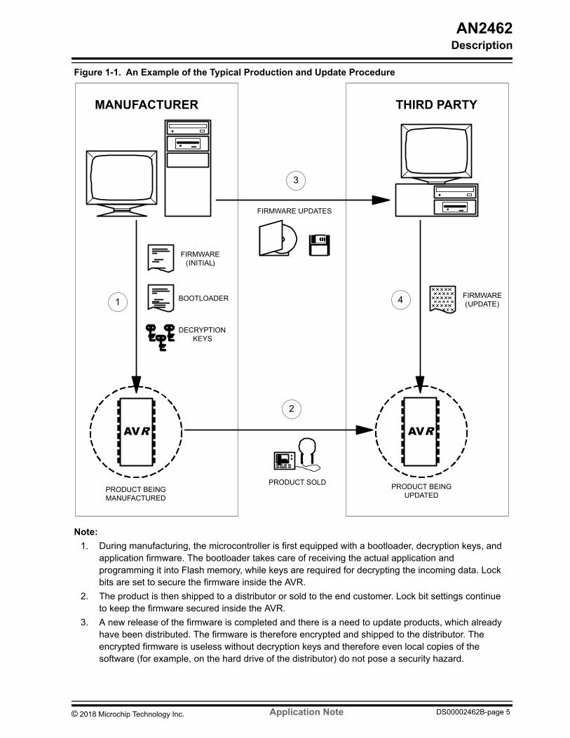
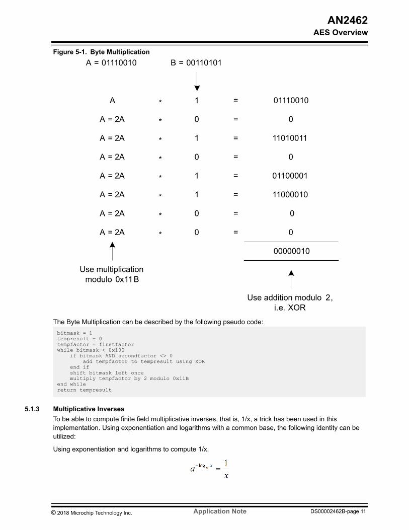
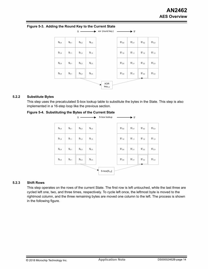
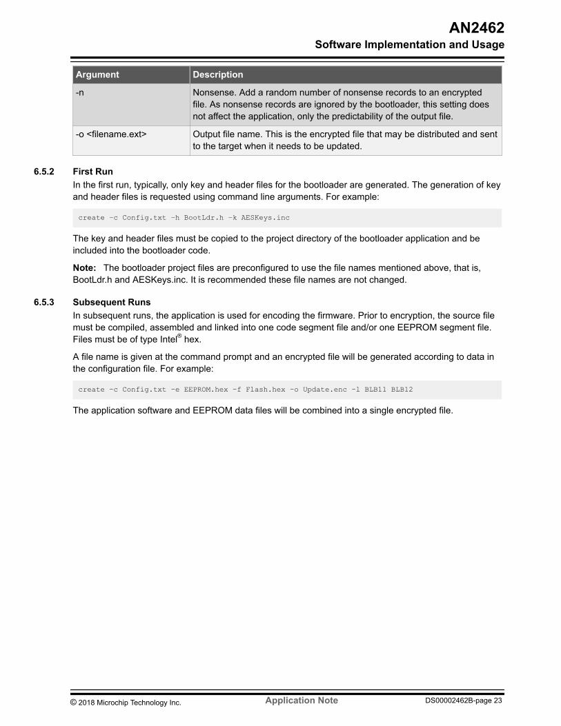
Argument Description
-n Nonsense Add a random number of nonsense records to an encryptedfile As nonsense records are ignored by the bootloader this setting doesnot affect the application only the predictability of the output file
-o ltfilenameextgt Output file name This is the encrypted file that may be distributed and sentto the target when it needs to be updated
652 First RunIn the first run typically only key and header files for the bootloader are generated The generation of keyand header files is requested using command line arguments For example
create ndashc Configtxt ndashh BootLdrh ndashk AESKeysinc
The key and header files must be copied to the project directory of the bootloader application and beincluded into the bootloader code
Note The bootloader project files are preconfigured to use the file names mentioned above that isBootLdrh and AESKeysinc It is recommended these file names are not changed
653 Subsequent RunsIn subsequent runs the application is used for encoding the firmware Prior to encryption the source filemust be compiled assembled and linked into one code segment file andor one EEPROM segment fileFiles must be of type Intelreg hex
A file name is given at the command prompt and an encrypted file will be generated according to data inthe configuration file For example
create ndashc Configtxt ndashe EEPROMhex ndashf Flashhex ndasho Updateenc ndashl BLB11 BLB12
The application software and EEPROM data files will be combined into a single encrypted file
AN2462Software Implementation and Usage
copy 2018 Microchip Technology Inc Application Note DS00002462B-page 23
654 Program FlowFigure 6-2 Flowchart of the Create Application
Create
Read config file
Command line arguments
How many keys
Use AES128
Use AES196
Use AES256
1 32
Key filename given
Create key file
Yes
Header filename given
Create header file
Yes
No
Flash filename given
Include flash filein encryption
Yes
EEPROM filename given
Include EEPROM filein encryption
Yes
No
No
Output filename given
Create encrypted file
Yes
No
No
Done
Done
Give instructions
No
Yes
655 The Encrypted FileThe Flash and EEPROM files are encrypted and stored in one target file Before encryption howeverdata is organized into records There are seven types of records as illustrated in the following figure
AN2462Software Implementation and Usage
copy 2018 Microchip Technology Inc Application Note DS00002462B-page 24
Figure 6-3 Record Types for Encrypted File
0
FLASH PAGE DATA (VARIABLE LENGTH)
2 NBAB
4 NBAB
3 NBAB
(VARIABLE LENGTH)5 NBAB
6 L R
7 R
FLASH PAGE PREPARE
END OF FRAME
FLASH PAGE PROGRAM
EEPROM SECTION DATA
LOCK BITS
RESET
RECORD TYPE LAYOUT
LEGEND
AB
LNB
R
ADDRESS IN BYTES
LOCK BITSLENGTH IN BYTES
RANDOM DATA
1 NBABFLASH PAGE ERASE
NNONSENSE
N ANY VALUE IN 8255
The record type is given as the first byte in the record The application data is broken down to recordtypes 1 2 3 and 4 (that is erase prepare load and write buffer page to Flash) The data for theEEPROM section is formatted into record type 5 Lock bits are sent in record type 6 Record types 0 and7 are for ending a frame and transmission respectively
All other records that is those with a record identifier above 7 are of type nonsense When this option isenabled (see create tool) a random number of nonsense records will be placed at random locations inthe file
The output file is created as illustrated in the following figure
Figure 6-4 Creating the Encrypted File
CHAINED AND ENCRYPTED DATA
INITIAL VECTOR
STEP 1
STEP 2
C
FZ
C
STEP 3
STEP 4
STEP 5
FRAMEFILE
CIPHER BLOCK
RECORD
CIPHER BLOCK CIPHER BLOCK CIPHER BLOCK CIPHER BLOCK
RECORDRECORDRECORD
CHAINED AND ENCRYPTED DATA
CHAINED AND ENCRYPTED DATA
The steps are described below (the numbers refer to the figure above)
AN2462Software Implementation and Usage
copy 2018 Microchip Technology Inc Application Note DS00002462B-page 25
1 Data is formatted into records which are then lined up following the frame signature (SIG) A zero(Z) is added to mark the end of the frame and the frame is padded with random data (F) to create aframe size that is a multiple of 16 bytes
2 The initial vector is attached to the frame In the first frame the vector is equal to the one given inthe configuration file In subsequent frames the initial vector is equal to the last cipher block of theprevious frame
3 The initial vector and cipher blocks are chained and encrypted The initial vector is then removedfrom the frame
4 A CRC-16 checksum (C) is calculated and added to the frame5 The length (L) of the frame excluding the length information is calculated and saved at the start of
the frame
The frame is written to the output file and the procedure is repeated until all data has been processed
66 PC Application ndash UpdateThis application is used for sending the encrypted file to the target The data can be sent via a serial porton the PC directly to the USART on the target hardware The program flow is illustrated as follows
AN2462Software Implementation and Usage
copy 2018 Microchip Technology Inc Application Note DS00002462B-page 26
Figure 6-5 Overview of the Project Flow
TwoArguments
YESNO
Update
Give Instructions
Read All File Into Buffer
Done
Done
FileExists
YESNO
Port NumberGiven
YESNO
PortInitializes
YESNO
Show Error Message
Show Error Message
Initialize Buffer Pointer
Read Size of Next Frame
Flush Input of Serial Port
Send Frame
ByteReceived
YES
NO
ByteValue
OKCRC
Retry lt 4YESNO
Show CRC Error Message Increase Retry Counter
Reset Retry Counter
Show Error Message
Close Serial Port
Close File
Pointer lt Sizeof Buffer
YESNO
Increase Pointer
Close File
The Update application reads in files generated with the Create application The file consists of one ormore concatenated frames of encrypted data The application transmits data one frame at a timepausing in between to wait for a reply from the bootloader The next frame is transmitted only after anacknowledgment has been received otherwise the application will either resend the frame or closecommunication
AN2462Software Implementation and Usage
copy 2018 Microchip Technology Inc Application Note DS00002462B-page 27
The update application is run from the command prompt The command prompt arguments are listed inthe table below
Table 6-4 Command Line Arguments for the Update Application
Argument Description
ltfilenameextgt The path to the encrypted file to be transferred
-COMn Serial port where n is the serial port number
-baudrate Baudrate where baudrate is the actual baudrate figure
For example
update blinkyext -COM1 -115200
It should be noted that the update system only updates those parts of the Flash and EEPROM denoted inthe application and EEPROM files If CRC check of the application section is enabled or the erase optionis selected in the create tool all application memory will be cleared before programming
AN2462Software Implementation and Usage
copy 2018 Microchip Technology Inc Application Note DS00002462B-page 28
7 Hardware SetupThe target hardware must be properly set up before the encrypted firmware can be sent to thebootloader In this application note it is assumed that an ATmega328PB Xplained Mini board is used forevaluation The details on configuration steps to program and debug are explained in the followingsections These sections cover only the basic information needed to get an ATmega328PB Xplained Miniup and running For more information refer to ATmega328PB Xplained Mini User Guide
71 Connecting the ATmega328PB Xplained Mini KitThis section helps the user to connect the ATmega328PB Xplained Mini with the Atmel Studio 7
1 Download and install Atmel Studio version 7 or later versions2 Launch the Atmel Studio3 Connect the ATmega328PB Xplained Mini to the USB port and it will be visible in the Atmel Studio
711 Auto Board Identification of Xplained Mini Kitbull Once the ATmega328PB Xplained Mini kit is connected to the PC the Windowsreg Task bar will pop-
up a message as shown belowFigure 7-1 ATmega328PB Xplained Mini Driver Installation
bull If the driver installation is proper EDBG will be listed in the Device Manager as shown below
AN2462Hardware Setup
copy 2018 Microchip Technology Inc Application Note DS00002462B-page 29
Figure 7-2 Successful mEDBG Driver Installation
bull Open Atmel Studio and go to View rarr Available Tools The EDBG should get listed in the tools asmEDBG and the tool status should display as Connected This indicates that the tool iscommunicating properly with Atmel Studio
Figure 7-3 mEDBG under Available Tools
712 Connect the ATmega328PB Xplained Mini UART to the mEDBG COM Port1 Connect the mEDBG USB to the PC2 Use the Device Manager to find the COM port number3 Default COM port settings are 9600 baud N 8 1 The COM port settings can be changed according
to the application by using the Device Manager This application has been tested with a baud rateof 115200
72 Programming and DebuggingThis section helps to program and debug the ATmega328PB Xplained Mini kit by using mEDBG
721 Programming the ATmega328PB Xplained Mini By Using mEDBG1 Connect the mEDBG USB to the PC2 Go to the Atmel Studio Click Tools select Device Programming and then select the connected
mEDBG as Tool with Device as ATmega328PB and Interface as ISP click Apply
AN2462Hardware Setup
copy 2018 Microchip Technology Inc Application Note DS00002462B-page 30
3 Select Memories and locate the source hex or elf file and then click Program4 If the source contains fuse settings go to Production file and upload the elf file and program the
fuses
Note If ISP programming fails it could be because the debugWIRE is enabled See 722 Debuggingthe ATmega328PB Xplained Mini By Using mEDBG on how to disable debugWIRE mode
722 Debugging the ATmega328PB Xplained Mini By Using mEDBG1 Start Atmel Studio2 Connect the mEDBG USB to the PC3 Open your project4 In the Project menu select the project properties page Select the Tools tab and select mEDBG
as debugger and debugWIRE as the interface5 In the Debug menu click Start Debugging and Break6 Atmel Studio will display an error message if the DWEN fuse in the ATmega328PB is not enabled
click YES to make Studio set the fuse using the ISP interface7 A debug session is started with a break in main Debugging can start8 When exiting debug mode select Disable debugWIRE and Close in the Debug menu This will
disable the DWEN fuse
Note 1 If the debug mode is not exited by selecting Disable debugWIRE and Close in the Debug menu
the DWEN fuse will be enabled and the target will still be in debug mode ie it will not be possibleto program the target by using the SPI (ISP) interface
2 The bootloader code supplied with this application note has been optimized for size and hence itmay not be possible to do debugging Removing the optimization will increase the code size and itmay not fit into the bootloader section Hence it is recommended to use only the programmingmode
AN2462Hardware Setup
copy 2018 Microchip Technology Inc Application Note DS00002462B-page 31
8 AVR BootloaderThe bootloader must reside in the target AVR before the device can be updated with encrypted firmwareThe bootloader communicates with the PC and is capable of programming the EEPROM and theapplication area of the Flash memory The bootloader included with this application note has beencreated by using Atmel Studio 7 The program flow is illustrated in the figure below
AN2462AVR Bootloader
copy 2018 Microchip Technology Inc Application Note DS00002462B-page 32
Figure 8-1 Flowchart for the AVR Bootloader
Switch SW7Pressed
YESNO
Bootldr
Load Initial Vector for CBC
Calculate CRC of Appl Section
ApplicationCRC Valid
YES
NO
Read Frame Size (Two Characters)
Read Character Store in RAM
Update Frame CRC Counter
Jump to Application
End ofFrame
YES
NO
Frame CRCValid
YES NO
Decrypt and Unchain Send Frame CRC Error
SignatureValid
YES NO
Ignore Frame BUT Send OKType
LoadData
WritePage
WriteEEPROM
WriteLock Bits
Set InitialVector
PreparePage
Send OK
PREPARE DATA PROGRAM EEPROM LOCKBITS RESET EOF
NOTE WELL IF CRC IS VALID FRAME ISDECRYPTED ANY INFORMATION SENTON DECRYPTION STATUS OTHER THANOK MAY BE USED IN AN ATTACK ATTEMPT
ErasePage
ERASE
CRC CheckEnabled
YES
NO
DoNothing
NONSENSE
81 Key and Header FilesBefore the bootloader can be compiled there are some parameters that need to be set up To start withthe encryption key and target header files generated by the PC application create must be copied to the
AN2462AVR Bootloader
copy 2018 Microchip Technology Inc Application Note DS00002462B-page 33
bootloader directory The files will be included when they are referred to with the include directive insidethe bootloader source code
82 Project FilesThe application note comes with device-specific project files for ATmega328PB
For other AVR devices use the project file and modify them as per the steps given in the followingsection
83 Atmel Studio and IAR SettingsThe common settings for Atmel Studio and IARtrade will be listed in this section
1 The essential fuse settings11 The boot reset vector must be enabled12 Set Low Fuse Byte to use External Clock 16 MHz to make the ATmega328PB example
(BAUD RATE 38400) download from Atmel START work properly2 The SPMCSR register address has to be defined using SPMREG (refer to the table below) macro
in regh file this register address will change if the register is located in the indirect memory regionthe address of this register can be found in the register summary section of the data sheetFigure 8-2 Setting SPMREG Address in regh
3 Other register addresses defined in regh file have to be modified according to the device datasheet
AN2462AVR Bootloader
copy 2018 Microchip Technology Inc Application Note DS00002462B-page 34
4 Symbol __RAMPZ__ (refer to the table below) has to be defined in compiler and assembler for thedevices with flash size greater than 64 KB
5 Symbol __MEMSPM__ (refer to the table below) has to be defined in assembler for the deviceswhose SPMCSR register is located above the direct memory access region (ie if SPMCSRregister is located above 0x3F) For eg ATmega128 has SPMCSR located at 0x68 and hence thedefinition is required for accessing it
6 Symbol BOOT_ADDR=ltbootloader section start addressgt (refer to the table below) has to bedefined in the compiler for the devices with flash size greater than 64 KB
Table 8-1 Summary of Symbol Settings
Setting M8 M16 M32 M64 M128 M256 M162 M169 M328PB M168PA
__RAMPZ__ No No No No Yes Yes No No No No
__MEMSPM__ No No No No Yes No No No No No
BOOT_ADDR No No No No 0x1E000 0x3E000 No No No No
BOOT_START(IAR) 0x1800 0x3800 0x7000 0xE000 0x1E000 0x3E000 0x3800 0x3800 0x7000 0x3800
text(Atmel Studio) 0x1800 0x3800 0x7000 0xE000 0x1E000 0x3E000 0x3800 0x3800 0x7000 0x3800
SPMREG 0x37 0x37 0x37 0x37 0x68 0x37 0x37 0x37 0x37 0x37
Note The value of BOOT_ADDRBOOT_START and text in the table above is the value when the bootsize is maximum You can change this value according to the actual boot size
831 Atmel Studio SettingsThe compiler linker and assembler setting shown below are required while configuring for a specificdevice in Atmel Studio
1 Bootloader start address text (refer to Table 8-1) has to be defined in the linker setting for linkingthe code to the bootloader start address (as shown in the figure below) Start address should begiven as byte address (multiplying word address by 2) For eg if bootloader word address ofATmega328PB is 0x3C00 corresponding byte would be 0x3C00 2 = 0x7800
AN2462AVR Bootloader
copy 2018 Microchip Technology Inc Application Note DS00002462B-page 35
Figure 8-3 Setting Bootloader Address Code Link Address
2 Optimization Settings (as shown in the figure below)Figure 8-4 Optimization Settings
3 Other Linker Settings (as shown in the figure below)
AN2462AVR Bootloader
copy 2018 Microchip Technology Inc Application Note DS00002462B-page 36
Figure 8-5 Other Linker Settings
832 IAR SettingsThe compiler linker and assembler settings shown below are required while configuring for a specificdevice in IAR
1 When using the mEDBG in the ATmega328PB Xplained Mini kit the Atmel-ICE should be selectedin Debugger Driver setting (as shown in the figure below)
AN2462AVR Bootloader
copy 2018 Microchip Technology Inc Application Note DS00002462B-page 37
Figure 8-6 Debugger Driver
2 A user-defined xcl file should be used to override default linker file Follow the steps below to makethe linker work properly21 Copy the template linker file (for example CProgram Files (x86)IAR SystemsEmbedded
Workbench 74avrsrctemplatecfgm328pbxcl) according to the device to your project andrename it what you like
22 Open this file and paste the below content under the original content and save it-ca90-w29
============================================================================= Interrupt vectors
-Z(CODE)INTVEC=BOOT_START-(BOOT_START+_X_INTVEC_SIZE-1)-H1895 -h(CODE)BOOT_START-(BOOT_START+_X_INTVEC_SIZE-1)
============================================================================= Code memory
-Z(CODE)NEAR_FHUGE_FSWITCHINITTABDIFUNCTCODE=BOOT_START-_X_FLASH_END-Z(FARCODE)FAR_FFARCODE=BOOT_START-_X_FLASH_END
============================================================================= RAM
AN2462AVR Bootloader
copy 2018 Microchip Technology Inc Application Note DS00002462B-page 38
-Z(DATA)NEAR_INEAR_Z=_X_SRAM_BASE-_X_SRAM_END-Z(DATA)RSTACK+_X_RSTACK_SIZE=(_X_SRAM_END-_X_RSTACK_SIZE+1)-_X_SRAM_END-Z(DATA)CSTACK+_X_CSTACK_SIZE=(_X_SRAM_END-_X_RSTACK_SIZE-_X_CSTACK_SIZE+1)-(_X_SRAM_END-_X_RSTACK_SIZE)-Z(DATA)RSTACK+40=(_X_SRAM_END-40+1)-_X_SRAM_END-Z(DATA)CSTACK+300=(_X_SRAM_END-40-300+1)-(_X_SRAM_END-40)-Z(DATA)TINY_ITINY_ZTINY_N=RAM_BASE-FF-Z(DATA)TINY_ITINY_ZTINY_N=RAM_BASE-100
23 Use this file to override the default linker file (as shown in the figure below)Figure 8-7 Override Default Linker File
24 Define BOOT_START (refer to Table 8-1) according to the device (as shown in the figurebelow)
AN2462AVR Bootloader
copy 2018 Microchip Technology Inc Application Note DS00002462B-page 39
Figure 8-8 Linker define
3 Optimization Settings (as shown in the figure below)
AN2462AVR Bootloader
copy 2018 Microchip Technology Inc Application Note DS00002462B-page 40
Figure 8-9 Optimization Settings
84 Installing the BootloaderCompile the bootloader and then download it to the target using Atmel Studio 7 or later Before runningthe bootloader the following fuse bits must be configured
bull Size of Boot Loader Section Set fuse bits so that the section size matches the BOOT_SIZE settingas described earlier Note that the BLS is usually given in words but the BOOT_SIZE parameter isgiven in bytes
bull Boot reset vector The boot reset vector must be enabledbull Oscillator options The oscillator fuse bits are device dependent They may require configuration
(affects USART)
Note Pay special attention in setting oscillator options correctly Even a small misadjustment couldresult in communication failure
Recommended fuse bit settings are provided in the table below See the device data sheet for detailedexplanation of device dependent fuse bits
AN2462AVR Bootloader
copy 2018 Microchip Technology Inc Application Note DS00002462B-page 41
Table 8-2 Recommended Fuse Bits
M8 M8515 M8535M16 M162 M169 M32M64
M128 328PB
BOOTSZ10 00 01 01
BOOTRST 0 0 0
Note ldquo0rdquo means programmed ldquo1rdquo means not programmed
It is recommended to program lock bits to protect both the application memory and the bootloader butonly after fuse bits have been set Lock bits can be programmed using Microchip IDE (Atmel Studio 7 orlater) BLS lock bits will also be set during firmware update provided that they have been defined ascommand line arguments when the firmware is encrypted The recommended lock bit settings are
bull Memory lock bits These should be set to prevent unauthorized access to memory Note that afterthe memory has been locked it cannot be accessed via in-system programming without erasing thedevice
bull Protection mode for Boot Loader Section SPM and LPM should not be allowed to write to or readfrom the BLS This will prevent the firmware in the application section to corrupt the bootloader andwill keep the decryption keys safe
bull Protection mode for application section No restrictions should be set for SPM or LPM accessingthe application section otherwise the bootloader cannot program it
Note It is important to understand that if the device is not properly locked then the memory can beaccessed via an ISP interface and the whole point of encrypting the firmware is gone
Recommended lock bit setting for present AVR MCUs are given in the table below See the device datasheet for a detailed explanation of lock bits
Table 8-3 Recommended Lock Bits
M8 M8515 M8535 M16
M162 M169 M32 M64 M128
328PB
BLB12 BLB11 0 0 0 0
BLB02 BLB01 1 1 1 1
LB2 LB1 0 0 0 0
85 PerformanceThe following sections summarize the system performance with respect to execution time and code size
851 Execution TimeThe time required for the target device to receive decode and program data depends on the followingfactors
bull File size The more data the longer it takesbull Baudrate The higher the transmission speed the shorter the transmission timebull Target AVR speed The higher the clock frequency the shorter the decoding time
AN2462AVR Bootloader
copy 2018 Microchip Technology Inc Application Note DS00002462B-page 42
bull Programming time of Flash page This is a device constant and cannot be alteredbull Key-size AES128 is faster to decrypt than AES256 In fact AES192 is slower than AES256 It has
something to do with 192 not being a power of 2bull Miscellaneous settings For example CRC check of application section takes short time
852 Code SizeUsing the highest optimization setting for the compiler the bootloader will fit nicely into 2 KB of Flashmemory
It should be noted that if no encryption keys are given the bootloader is built without AES support Thisapplication note then performs as a standard bootloader system and can be used on any AVR withbootloader support
AN2462AVR Bootloader
copy 2018 Microchip Technology Inc Application Note DS00002462B-page 43
9 SummaryThis application note has presented a method for transferring data securely to an AVR microcontrollerwith bootloader capabilities This document has also highlighted techniques that should be implementedwhen building a secured system The following issues should be considered in order to increase thesecurity of an AVR design
Implement a bootloader that supports downloading in encrypted form When the bootloader is firstinstalled (during manufacturing) it must be equipped with decryption keys required for future firmwareupdates The firmware can then be distributed in an encrypted form securing the contents from outsiders
Use AVR lock bits to secure Application and Boot Loader sections When lock bits are set to preventreading from the device the memory contents cannot be retrieved If lock bits are not set there is no useencrypting the firmware
Encrypt the firmware before distribution Encrypted software is worthless to any outside the entity withoutthe proper decryption keys
Keep encryption keys safe Encryption keys should be stored in two places only in the bootloader whichhas been secured by lock bits and in the firmware development bench at the manufacturer
Chain encrypt data When data is chained each encrypted block depends on the previous block As aconsequence equal plaintext blocks produce different encrypted outputs
Avoid standard predictable patterns in the firmware Most programs have a common framework and anypredictable patterns such as an interrupt vector table starting with a jump to a low address only serve tohelp the intruder Also avoid padding unused memory areas with a constant number
Hide the method There is no need to mention which algorithm is being used or what the key length isThe less the intruder knows about the system the better It may be argued that knowing the encryptionmethod fends off some attackers but knowing nothing about the method increases the effort and mayfend off even more
The bootloader may also be used to erase the application section if required Many attack attemptsinclude removing the device from its normal working environment and powering it up in a hacking benchDetecting for example that an LCD is missing or that there are CRC errors in the memory thebootloader may initiate a complete erase of all memory (including the bootloader section and decryptionkeys)
In applications where it is not feasible or possible to use an external communications channel forupdates the firmware can be stored in one of the CryptoMemoryreg devices The memory can bepackaged as a removable smart card which can easily be inserted in a slot of the device when anupgrade is needed The microcontroller can check for the presence of a CryptoMemory upon start-up andretrieve a firmware upgrade as needed
Use secure hardware A strong encryption protocol is useless if the hardware has structural flaws Thereare no reported security issues with the AVR microcontrollers
This list can be made much longer but the purpose of it is merely to set the designer off in the rightdirection Do not underestimate the wit or endurance of your opponent
AN2462Summary
copy 2018 Microchip Technology Inc Application Note DS00002462B-page 44
10 Get Source Code from Atmel | STARTThe example code is available through Atmel | START which is a web-based tool that enablesconfiguration of application code through a Graphical User Interface (GUI) The code can be downloadedfor both Atmel Studio and IAR Embedded Workbenchreg via the direct example code-link(s) below or theBROWSE EXAMPLES button on the Atmel | START front page
Atmel | START web page httpstartatmelcom
Example Code
bull AVR231 AES Bootloaderndash httpstartatmelcomexampleAtmelAVR231_AES_Bootloader
001ApplicationAVR231_AES_Bootloader
Press User guide in Atmel | START for details and information about example projects The User guidebutton can be found in the example browser and by clicking the project name in the dashboard viewwithin the Atmel | START project configurator
Atmel Studio
Download the code as an atzip file for Atmel Studio from the example browser in Atmel | START byclicking DOWNLOAD SELECTED EXAMPLE To download the file from within Atmel | START clickEXPORT PROJECT followed by DOWNLOAD PACK
Double-click the downloaded atzip file and the project will be imported to Atmel Studio 70
IAR Embedded Workbench
For information on how to import the project in IAR Embedded Workbench open the Atmel | START userguide select Using Atmel Start Output in External Tools and IAR Embedded Workbench A link to theAtmel | START user guide can be found by clicking About from the Atmel | START front page or Help AndSupport within the project configurator both located in the upper right corner of the page
AN2462Get Source Code from Atmel | START
copy 2018 Microchip Technology Inc Application Note DS00002462B-page 45
11 Referencesbull ATmega328PB data sheet (httpwwwmicrochipcomwwwproductsenatmega328pb)bull ATmega328PB Xplained Mini kit (httpwwwmicrochipcomdevelopmenttoolsproductdetailsaspx
partno=atmega328pb-xmini)bull Atmel Studio (httpwwwatmelcomtoolsatmelstudioaspxtab=overview)bull Atmel START (httpstartatmelcom)bull AT10764 (httpww1microchipcomdownloadsenappnotesatmel-42508-software-library-for-
aes-128-encryption-and-decryption_applicationnote_at10764pdf)bull AVR230 DES Bootloader (httpww1microchipcomdownloadsenappnotesdoc2541pdf )bull Handbook of Applied Cryptography (httpcacruwaterloocahac)bull AES Specification (httpcsrcnistgovpublicationsfipsfips197fips-197pdf)
AN2462References
copy 2018 Microchip Technology Inc Application Note DS00002462B-page 46
12 Revision HistoryDoc Rev Date Comments
B 042018 Section Get Source Code from Atmel START is added with the link to AtmelSTART example code
A 062017 Converted to Microchip format and replaced the Atmel document number 2589The document is updated and the application code is tested for the ATmega328PBdevice
2589E 032012 New templateSection PC Application is updated
Fixed wrong interrupt vector size in the ATmega32 project
Removed cycle dependance on data
2589D 082006 Some minor fixes
AN2462Revision History
copy 2018 Microchip Technology Inc Application Note DS00002462B-page 47
The Microchip Web Site
Microchip provides online support via our web site at httpwwwmicrochipcom This web site is used asa means to make files and information easily available to customers Accessible by using your favoriteInternet browser the web site contains the following information
bull Product Support ndash Data sheets and errata application notes and sample programs designresources userrsquos guides and hardware support documents latest software releases and archivedsoftware
bull General Technical Support ndash Frequently Asked Questions (FAQ) technical support requestsonline discussion groups Microchip consultant program member listing
bull Business of Microchip ndash Product selector and ordering guides latest Microchip press releaseslisting of seminars and events listings of Microchip sales offices distributors and factoryrepresentatives
Customer Change Notification Service
Microchiprsquos customer notification service helps keep customers current on Microchip productsSubscribers will receive e-mail notification whenever there are changes updates revisions or erratarelated to a specified product family or development tool of interest
To register access the Microchip web site at httpwwwmicrochipcom Under ldquoSupportrdquo click onldquoCustomer Change Notificationrdquo and follow the registration instructions
Customer Support
Users of Microchip products can receive assistance through several channels
bull Distributor or Representativebull Local Sales Officebull Field Application Engineer (FAE)bull Technical Support
Customers should contact their distributor representative or Field Application Engineer (FAE) for supportLocal sales offices are also available to help customers A listing of sales offices and locations is includedin the back of this document
Technical support is available through the web site at httpwwwmicrochipcomsupport
Microchip Devices Code Protection Feature
Note the following details of the code protection feature on Microchip devices
bull Microchip products meet the specification contained in their particular Microchip Data Sheetbull Microchip believes that its family of products is one of the most secure families of its kind on the
market today when used in the intended manner and under normal conditionsbull There are dishonest and possibly illegal methods used to breach the code protection feature All of
these methods to our knowledge require using the Microchip products in a manner outside theoperating specifications contained in Microchiprsquos Data Sheets Most likely the person doing so isengaged in theft of intellectual property
bull Microchip is willing to work with the customer who is concerned about the integrity of their code
AN2462
copy 2018 Microchip Technology Inc Application Note DS00002462B-page 48
bull Neither Microchip nor any other semiconductor manufacturer can guarantee the security of theircode Code protection does not mean that we are guaranteeing the product as ldquounbreakablerdquo
Code protection is constantly evolving We at Microchip are committed to continuously improving thecode protection features of our products Attempts to break Microchiprsquos code protection feature may be aviolation of the Digital Millennium Copyright Act If such acts allow unauthorized access to your softwareor other copyrighted work you may have a right to sue for relief under that Act
Legal Notice
Information contained in this publication regarding device applications and the like is provided only foryour convenience and may be superseded by updates It is your responsibility to ensure that yourapplication meets with your specifications MICROCHIP MAKES NO REPRESENTATIONS ORWARRANTIES OF ANY KIND WHETHER EXPRESS OR IMPLIED WRITTEN OR ORAL STATUTORYOR OTHERWISE RELATED TO THE INFORMATION INCLUDING BUT NOT LIMITED TO ITSCONDITION QUALITY PERFORMANCE MERCHANTABILITY OR FITNESS FOR PURPOSEMicrochip disclaims all liability arising from this information and its use Use of Microchip devices in lifesupport andor safety applications is entirely at the buyerrsquos risk and the buyer agrees to defendindemnify and hold harmless Microchip from any and all damages claims suits or expenses resultingfrom such use No licenses are conveyed implicitly or otherwise under any Microchip intellectualproperty rights unless otherwise stated
Trademarks
The Microchip name and logo the Microchip logo AnyRate AVR AVR logo AVR Freaks BeaconThingsBitCloud CryptoMemory CryptoRF dsPIC FlashFlex flexPWR Heldo JukeBlox KeeLoq KeeLoq logoKleer LANCheck LINK MD maXStylus maXTouch MediaLB megaAVR MOST MOST logo MPLABOptoLyzer PIC picoPower PICSTART PIC32 logo Prochip Designer QTouch RightTouch SAM-BASpyNIC SST SST Logo SuperFlash tinyAVR UNIO and XMEGA are registered trademarks ofMicrochip Technology Incorporated in the USA and other countries
ClockWorks The Embedded Control Solutions Company EtherSynch Hyper Speed Control HyperLightLoad IntelliMOS mTouch Precision Edge and Quiet-Wire are registered trademarks of MicrochipTechnology Incorporated in the USA
Adjacent Key Suppression AKS Analog-for-the-Digital Age Any Capacitor AnyIn AnyOut BodyComchipKIT chipKIT logo CodeGuard CryptoAuthentication CryptoCompanion CryptoControllerdsPICDEM dsPICDEMnet Dynamic Average Matching DAM ECAN EtherGREEN In-Circuit SerialProgramming ICSP Inter-Chip Connectivity JitterBlocker KleerNet KleerNet logo Mindi MiWimotorBench MPASM MPF MPLAB Certified logo MPLIB MPLINK MultiTRAK NetDetach OmniscientCode Generation PICDEM PICDEMnet PICkit PICtail PureSilicon QMatrix RightTouch logo REALICE Ripple Blocker SAM-ICE Serial Quad IO SMART-IS SQI SuperSwitcher SuperSwitcher II TotalEndurance TSHARC USBCheck VariSense ViewSpan WiperLock Wireless DNA and ZENA aretrademarks of Microchip Technology Incorporated in the USA and other countries
SQTP is a service mark of Microchip Technology Incorporated in the USA
Silicon Storage Technology is a registered trademark of Microchip Technology Inc in other countries
GestIC is a registered trademark of Microchip Technology Germany II GmbH amp Co KG a subsidiary ofMicrochip Technology Inc in other countries
All other trademarks mentioned herein are property of their respective companies
AN2462
copy 2018 Microchip Technology Inc Application Note DS00002462B-page 49
copy 2018 Microchip Technology Incorporated Printed in the USA All Rights Reserved
ISBN 978-1-5224-2831-2
Quality Management System Certified by DNV
ISOTS 16949Microchip received ISOTS-169492009 certification for its worldwide headquarters design and waferfabrication facilities in Chandler and Tempe Arizona Gresham Oregon and design centers in Californiaand India The Companyrsquos quality system processes and procedures are for its PICreg MCUs and dsPICreg
DSCs KEELOQreg code hopping devices Serial EEPROMs microperipherals nonvolatile memory andanalog products In addition Microchiprsquos quality system for the design and manufacture of developmentsystems is ISO 90012000 certified
AN2462
copy 2018 Microchip Technology Inc Application Note DS00002462B-page 50
AMERICAS ASIAPACIFIC ASIAPACIFIC EUROPECorporate Office2355 West Chandler BlvdChandler AZ 85224-6199Tel 480-792-7200Fax 480-792-7277Technical SupporthttpwwwmicrochipcomsupportWeb AddresswwwmicrochipcomAtlantaDuluth GATel 678-957-9614Fax 678-957-1455Austin TXTel 512-257-3370BostonWestborough MATel 774-760-0087Fax 774-760-0088ChicagoItasca ILTel 630-285-0071Fax 630-285-0075DallasAddison TXTel 972-818-7423Fax 972-818-2924DetroitNovi MITel 248-848-4000Houston TXTel 281-894-5983IndianapolisNoblesville INTel 317-773-8323Fax 317-773-5453Tel 317-536-2380Los AngelesMission Viejo CATel 949-462-9523Fax 949-462-9608Tel 951-273-7800Raleigh NCTel 919-844-7510New York NYTel 631-435-6000San Jose CATel 408-735-9110Tel 408-436-4270Canada - TorontoTel 905-695-1980Fax 905-695-2078
Australia - SydneyTel 61-2-9868-6733China - BeijingTel 86-10-8569-7000China - ChengduTel 86-28-8665-5511China - ChongqingTel 86-23-8980-9588China - DongguanTel 86-769-8702-9880China - GuangzhouTel 86-20-8755-8029China - HangzhouTel 86-571-8792-8115China - Hong Kong SARTel 852-2943-5100China - NanjingTel 86-25-8473-2460China - QingdaoTel 86-532-8502-7355China - ShanghaiTel 86-21-3326-8000China - ShenyangTel 86-24-2334-2829China - ShenzhenTel 86-755-8864-2200China - SuzhouTel 86-186-6233-1526China - WuhanTel 86-27-5980-5300China - XianTel 86-29-8833-7252China - XiamenTel 86-592-2388138China - ZhuhaiTel 86-756-3210040
India - BangaloreTel 91-80-3090-4444India - New DelhiTel 91-11-4160-8631India - PuneTel 91-20-4121-0141Japan - OsakaTel 81-6-6152-7160Japan - TokyoTel 81-3-6880- 3770Korea - DaeguTel 82-53-744-4301Korea - SeoulTel 82-2-554-7200Malaysia - Kuala LumpurTel 60-3-7651-7906Malaysia - PenangTel 60-4-227-8870Philippines - ManilaTel 63-2-634-9065SingaporeTel 65-6334-8870Taiwan - Hsin ChuTel 886-3-577-8366Taiwan - KaohsiungTel 886-7-213-7830Taiwan - TaipeiTel 886-2-2508-8600Thailand - BangkokTel 66-2-694-1351Vietnam - Ho Chi MinhTel 84-28-5448-2100
Austria - WelsTel 43-7242-2244-39Fax 43-7242-2244-393Denmark - CopenhagenTel 45-4450-2828Fax 45-4485-2829Finland - EspooTel 358-9-4520-820France - ParisTel 33-1-69-53-63-20Fax 33-1-69-30-90-79Germany - GarchingTel 49-8931-9700Germany - HaanTel 49-2129-3766400Germany - HeilbronnTel 49-7131-67-3636Germany - KarlsruheTel 49-721-625370Germany - MunichTel 49-89-627-144-0Fax 49-89-627-144-44Germany - RosenheimTel 49-8031-354-560Israel - RarsquoananaTel 972-9-744-7705Italy - MilanTel 39-0331-742611Fax 39-0331-466781Italy - PadovaTel 39-049-7625286Netherlands - DrunenTel 31-416-690399Fax 31-416-690340Norway - TrondheimTel 47-7289-7561Poland - WarsawTel 48-22-3325737Romania - BucharestTel 40-21-407-87-50Spain - MadridTel 34-91-708-08-90Fax 34-91-708-08-91Sweden - GothenbergTel 46-31-704-60-40Sweden - StockholmTel 46-8-5090-4654UK - WokinghamTel 44-118-921-5800Fax 44-118-921-5820
Worldwide Sales and Service
copy 2018 Microchip Technology Inc Application Note DS00002462B-page 51
- Introduction
- Features
- Table of Contents
- 1 Description
- 2 Glossary
- 3 Pre-Requisites
- 4 Cryptography Overview
-
- 41 Encryption
- 42 Decryption
-
- 5 AES Overview
-
- 51 AES Implementation
-
- 511 Byte Addition
- 512 Byte Multiplication
- 513 Multiplicative Inverses
- 514 S-Boxes
- 515 The lsquoStatersquo
-
- 52 AES Encryption
-
- 521 Add Round Key
- 522 Substitute Bytes
- 523 Shift Rows
- 524 Mix Columns
-
- 53 AES Decryption
- 54 Key Expansion
- 55 Cipher Block Chaining ndash CBC
-
- 6 Software Implementation and Usage
-
- 61 Motivation
- 62 Usage Overview
- 63 Configuration File
- 64 PC Application ndash GenTemp
- 65 PC Application ndash Create
-
- 651 Command Line Arguments
- 652 First Run
- 653 Subsequent Runs
- 654 Program Flow
- 655 The Encrypted File
-
- 66 PC Application ndash Update
-
- 7 Hardware Setup
-
- 71 Connecting the ATmega328PB Xplained Mini Kit
-
- 711 Auto Board Identification of Xplained Mini Kit
- 712 Connect the ATmega328PB Xplained Mini UART to the mEDBG COM Port
-
- 72 Programming and Debugging
-
- 721 Programming the ATmega328PB Xplained Mini By Using mEDBG
- 722 Debugging the ATmega328PB Xplained Mini By Using mEDBG
-
- 8 AVR Bootloader
-
- 81 Key and Header Files
- 82 Project Files
- 83 Atmel Studio and IAR Settings
-
- 831 Atmel Studio Settings
- 832 IAR Settings
-
- 84 Installing the Bootloader
- 85 Performance
-
- 851 Execution Time
- 852 Code Size
-
- 9 Summary
- 10 Get Source Code from Atmel | START
- 11 References
- 12 Revision History
- The Microchip Web Site
- Customer Change Notification Service
- Customer Support
- Microchip Devices Code Protection Feature
- Legal Notice
- Trademarks
- Quality Management System Certified by DNV
- Worldwide Sales and Service
-
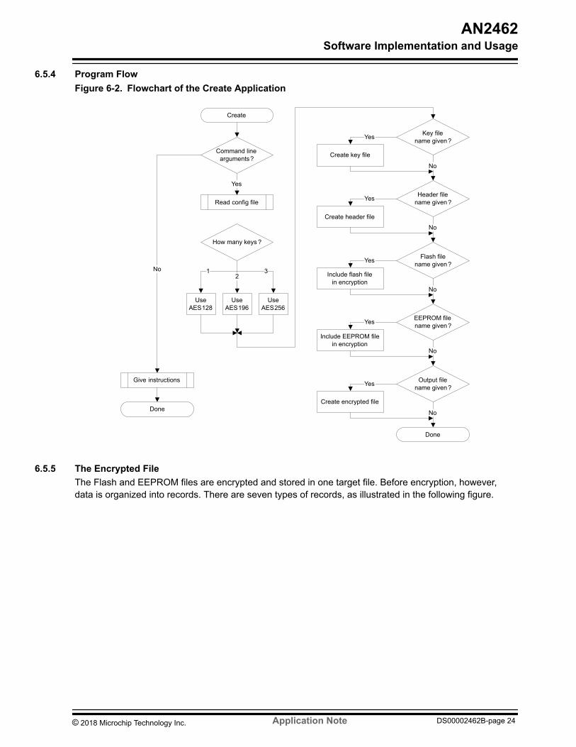
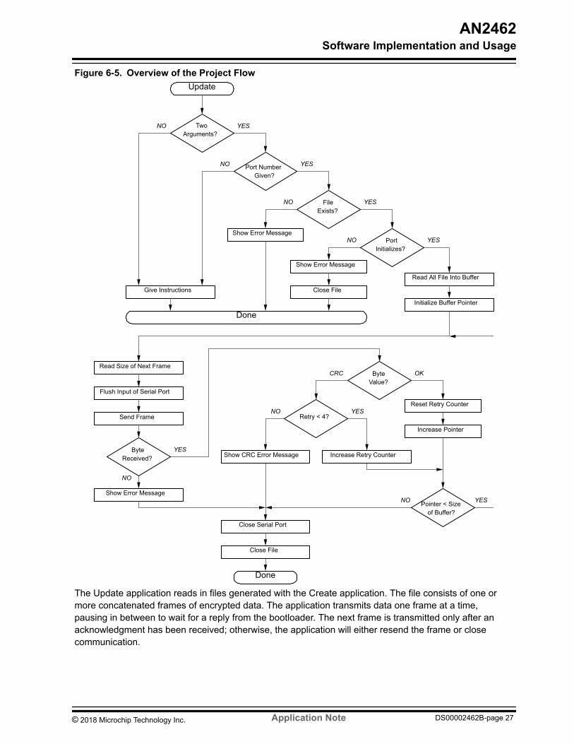
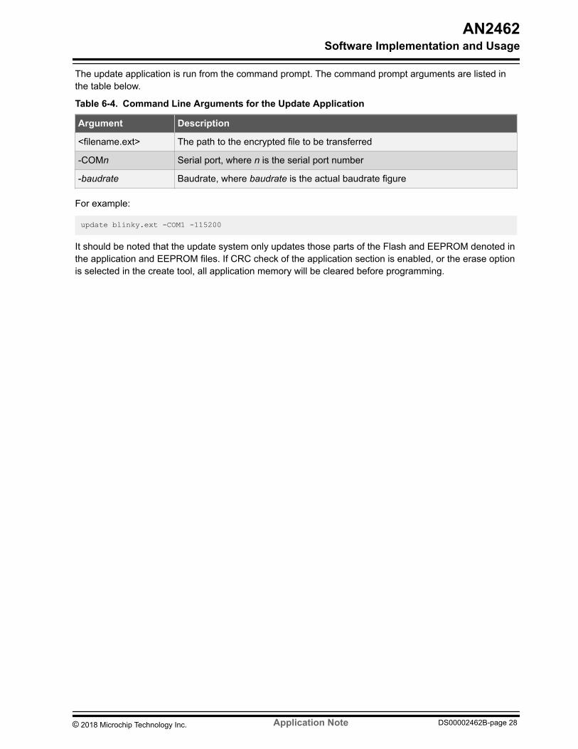
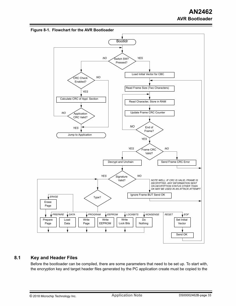
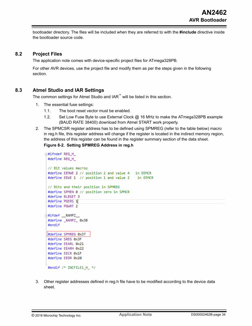
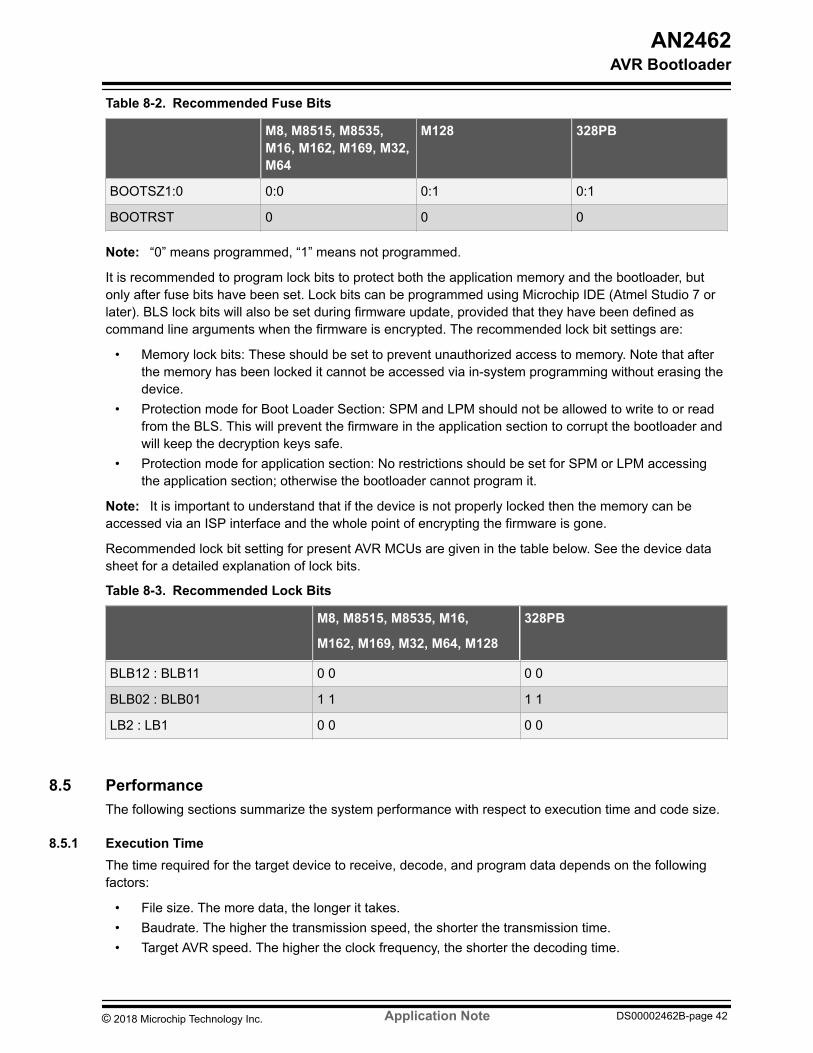
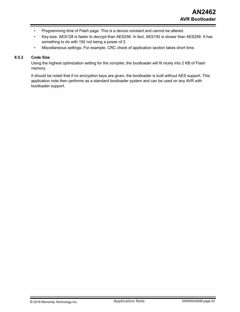