awips ii user functional evaluation plan - national · pdf file · 2008-05-01awips...
TRANSCRIPT
i
AWIPS II User Functional Evaluation Plan
May 1, 2008
Prepared by: The National Weather Service Office of Science and Technology / Systems Engineering Center, Office of Climate Water and Weather Services, Office of Operational Systems, and National Centers for Environmental Prediction

ii
Table of Contents Executive Summary …………………………………………………………………v Revision History ……………………………………………………………………vi Acronyms …………………………………………………………………………..vii Part I. Overview…………………………………………………………………….1 1. Introduction………………………………………………………………………1
1.1. Background………………………………………………………………….1 1.1.1. AWIPS Evolution / AWIPS II…...…………………………………..1 1.1.2. AWIPS II Development …………………….……………………….2 1.1.3. AWIPS II Testing Overview………...……………………………….2
1.1.3.1. Testing Roadmap ……………………………………………3 1.1.4. Government Testing Overview ……………………………………...4
1.1.4.1. User Functional Evaluation ………………………………….4 1.1.4.2. Special Considerations of AWIPS II Testing ………………..4
2. UFE Planning……………………………………………………………………..5 2.1. Purpose………………………………………………………………………5 2.2. UFE Objectives……………………………………………………………...5 2.3. UFE Assessment Criteria……………………………………………………6 2.4. UFE Strategy………………………………………………………………...7 2.5. UFEH ……………………………………………………………………….7 2.6. UFER ………………………………………………………………………..8 2.7. UFEW / UFEC……………………………………………………………….8 2.8. UFEN ……………………………………………………………………….9 2.9. System Operating Environment……………………………………………..9
2.9.1. Hardware Platforms ………………………………………………….9 2.9.2. Software Configuration ………………………………………………9
2.9.2.1. Task Order #8 ………………………………………………..9 2.9.2.2. Task Order #9 ………………………………………………..9 2.9.2.3. Task Order #10 ………………………………………….…..10 2.9.2.4. Task Order #11 ………………………………………….…..10
2.10. Conduct and Duration ……………………………………………….10 3. Prerequisites, Assumptions, and Risks ………………………………………….11
3.1. UFE Prerequisite…………………………………………………………….11 3.2. Assumptions/Limitations …………………………………………………...11 3.3. Risks and Mitigation Strategies ……………………………………………..11
4. Data Collection …………………………………………………………………..12 4.1. Field Data Collection ……………………………………………………….12 4.2. Site Support ………………………………………………………………...12
5. Test Management ………………………………………………………………..12 5.1. UFE Review Group ………………………………………………………...12 5.2. NWS National Headquarters Support ………………………………………13
5.2.1. AWIPS II Project Manager …………………………………………..13 5.2.2. AWIPS II Test Manager ……………………………………………..13 5.2.3. UFE Manager …………………………………………………………13 5.2.4. WSH Test Team Members …………………………………………...14
iii
5.2.5. OCWWS Coordination Lead ………………………………………..14 5.2.6. Product and Service Area Leads (PSAL) …………………………...14 5.2.7. Systems Lead (SFP) ………………………………………………...15 5.2.8. Communications Networks and Interfaces Lead (CNIL) …………...16 5.2.9. Local Applications Migration Team ………………………………..16
5.3. UFE Regional Focal Points…………………………………………………16 5.4. UFE Site Level Focal Points ……………………………………………….17
5.4.1. UFE Site Focal Points ………………………………………………17 5.4.2. Forecasters and Hydrologists (F&H) ……………………………….17 5.4.3. Electronic Systems Analyst and Information Technology Officer …17
5.5. URG Members ……………………………………………………………..18 5.6. Data Management ………………………………………………………….19 5.7. Corrective Process ………………………………………………………….19
5.7.1. System-Level Problems ……………………………………………..20
Part II Methodology 1. Approach ………………………………………………………………………..20 2. UFE Sites ………………………………………………………………………..21
2.1. Site Selection Criteria ………………………………………………………21 2.2. Regional and Field Test Sites ………………………………………………21
3. Documentation …………………………………………………………………..22 3.1. Test Scenarios ………………………………………………………………23 3.2. Training ……………………………………………………………………..23
3.2.1. UFE Criteria …………………………………………………………23
Part III Reporting 1. Reports ………………………………………………………………………….23 2. Data Analysis …………………………………………………………………...23
Appendices Appendix A: Test Trouble Report Tool A-# A1: UFE Test Trouble Report Form A-# A2: UFE Test Trouble Report Worksheet A-# A3: UFE TTR Worksheet Form Instructions A-# Appendix B: UFE Test Case Scenario Plan B-# Appendix C: UFE Guidelines C-# Appendix D: UFE Survey D-# Appendix E: UFE Product Summary E-# Tables & Figures
iv
Table 1: UFE Team (UFEET) # Table 2: UFE Sites # Figure A.1 – TTR Login Page A-# Figure A.2 – TTR Sample Page A-# Figure A.3 – Detailed TTR Form A-# Figure A.4 – TTR Custom Page A-# Figure D.1 – UFE Survey Form D-# Figure E.1 – Sample UFE Product Summary Page E-#

v
Executive Summary
This document describes the plan for performing a User Functional Evaluation (UFE) of the National Oceanic and Atmospheric Administration’s (NOAA), National Weather Service (NWS) Advanced Weather Interactive Processing System II (AWIPS II). NWS will use the UFE results, along with other inputs to determine the readiness to perform the AWIPS II Operational Test and Evaluation (OT&E), scheduled for September 2009. The Government-led UFE will begin in February 2008, following the successful completion of a delivery acceptance test for the Raytheon delivered Task Order #8 (under Contract DG133W-05-CQ-1067). Each subsequent Raytheon delivered task order, through T.O. #11, will include a UFE period of performance which will performed on platforms located at NWS HQ, Regional HQ(s), and Weather Service Forecast Offices(s) (WFO). A Test Review Group (TRG) will oversee completion of each UFE (one for each T.O. - four in all). The TRG will review UFE activities, classify any problems identified during the UFE, and coordinate resolution of issues/problems discovered. Upon the completion of all UFEs, the TRG will recommend whether to proceed with the AWIPS II OT&E. The UFE Plan is comprised of three parts: • Part I contains introductory materials – background, purpose, strategies, objectives, entrance and
exit criteria, support philosophies, prerequisites, overall management structure, and assumptions/limitations.
• Part II describes the UFE methodology to be executed during each of the four planned Task Orders (T.O. 8 – 11). Included in this part of the plan is the UFE approach, identification of supporting sites/platforms (e.g., NWS HQ , Regional HQ, WFOs, and RFCs), UFE documentation (e.g. test procedures and scenarios), problem tracking and adjudication, and scheduling information.
• Part III discusses the preparation of the UFE Report for each T.O.

vi
Acronyms ACCB AWIPS Configuration Control Board AELC The AWIPS II PM is also a member of the AELC and reports the
recommendations of the URG to the AELC and to the members of OSIP Gate 4
ARH Alaska Region Headquarters AWC Aviation Weather Center AWIPS Advanced Weather Interactive Processing System C&A Security Certification and Accreditation CAVE Common AWIPS Visualization Environment CIO Chief Information Officer CONUS Contiguous United States CRH NWS Central Region Headquarters CWF Coastal Water Forecasts CWFA County Warning Forecast Area DR Descepancy Report DT&E Developmental Test and Evaluation FSOC Field Systems Operations Center HIC Hydrologist-In-Charge IT Information Technology ITSO Information Technology Security Office IV&V Independent Validation and Verification GLF Great Lakes Forecast ERH NWS Eastern Region Headquarters MIC Meteorologist-in-Charge MND Mass News Dissemination MSD Meteorological Services Division NAWIPS National Centers AWIPS NCEP National Centers for Environmental Prediction NCF AWIPS Network Control Facility NOAA National Oceanic and Atmospheric Administration NSH Near Shore Forecast NWS National Weather Service NWSI NWS Instruction O&M Operations and Maintenance OB Operational Build OCONUS Outside the Contiguous United States OCWWS Office of Climate, Water, and Weather Services OFF Off Shore Forecast OOS Office of Operational Systems OPS24 Field Systems Operations Center, Test and Evaluation Branch OSIP Operations and Services Improvement Process OST Office of Science and Technology OST31 Office of Science and Technology, Systems Engineering Center,
Analysis Branch OST32 Office of Science and Technology, Systems Engineering Center,
Development Branch

vii
OT&E Operational Test and Evaluation PAMS Product Availability Monitoring System POC Point of Contact PRH NWS Pacific Region Headquarters PSAL Product and Service Area Leads RFC River Forecast Center SEC Systems Engineering Center SEL Severe Local Storm Public Watch Narrative SLS NWSFO/NWSO Convective Watch County Listing SOA Service-Oriented Architecture SST AWIPS Site Support Team SVS Severe Weather Statement SPC Storm Prediction Center SRH NWS Southern Region Headquarters ST System Test SVR System Verification Review TPC Tropical Prediction Center TRG Test Review Group TTR Test Trouble Report UFE User Functional Evaluation UFEH UFE performed on a WSH designated test bed (e.g. NMTW, NMTR
NHDA, or NHOW) UFER UFE performed at Regional Headquarters site UFEC UFE performed at River Forecast Office UFEM UFE Manager UFEN UFE conducted on AWIPS platforms at designated National Centers UFEW UFE performed at Weather Forecast Office sites UGC Universal Geographic Code URG UFE Review Group VTEC Valid Time Event Code WarnGen Warning Generation software application WBC Watch By County WCL Watch County List WCM Warning Coordination Meteorologist WCN Watch County Notification WDTB Warning Decision Training Branch WFO Weather Forecast Office WOU Watch Outline Update message WRH NWS Western Region Headquarters WSH National Weather Service Headquarters WTT WSH Test Team members
1
Part I. Overview
1 Introduction
1.1 Background
1.1.1 AWIPS II Development AWIPS II’s comprehensive implementation strategy includes a development period to implement the AWIPS I functionality and operability on the new AWIPS II system architecture
a) Four incremental software deliverables, known as Task Orders, will be used to deliver AWIPS I
functionality and operability (e.g. T.O. #8, T.O. #9, T.O. #10, and T.O. #11)
b) Target task order delivery (based on completion of T.O. Out Brief):
i. T.O.8 - February 2008 ii. T.O.9 - September 2008 iii. T.O.10 - January 2009 iv. T.O.11 - June 2009
1.1.2 Government Testing Over the next two plus years, spanning TO8 delivery through preparations for AWIPS II deployment, the NWS will conduct several types of tests, evaluations, and reviews of AWIPS II. The tests will include Independent Validation and Verification (IV&V), User Functional Evaluation (UFE), security Certification and Accreditation (C&A), and Operational Test and Evaluation (OT&E). The NWS is responsible for the planning and execution of these tests and evaluations. However, Raytheon will provide technical support depending on the specific testing. Support may take the form of fixing “work stops,” processing trouble tickets, providing discrepancy disposition reports, and assisting in defining performance test procedures. Details of this testing are beyond the scope of this document; however, a few points on each are provided in this section.
1.1.2.1 User Functional Evaluation (UFE) UFEs will be performed following the Out-Brief for T.O.s 8, 9, 10, and 11. It is similar to the Pre-Integration Test (PIT) done today for new functionality, though the period of performance is approximately 120 days. It will provide for tests of “forecaster functionality” and will be performed by NWS headquarters, regional field personnel (e.g., forecasters). The primary purpose of the UFE is to verify that the functionality adequately duplicates AWIPS I end-user functions delivered with a specific T.O. Raytheon’s technical support will consist of fixing work stops, and providing a disposition report for discrepancies (i.e..,DRs) submitted to Raytheon during the UFE period of performance. UFE (described per this plan) includes field forecasters from both WFOs and RFCs, evaluating the functionality, operability, performance, and other system characteristics of the T.O. under review at designated test sites, employing both formal (test procedure/scenario based) and informal (i.e, adhoc) testing practices.

2
2 UFE Planning
2.1 Purpose The UFE for each T.O. will be used to verify AWIPS II system functionality, operability, stability, and usability under operational type conditions as part of the system readiness verification effort for the start of AWIPS II OT&E, scheduled for the first quarter of FY 2010. During the UFE period of performance field forecasters and other UFE team members will be given their first extensive opportunity to assess the “look and feel” portion of the AWIPS I to AWIPS II baseline application migration, localization and customization, system administration functions with local variants (when available), local applications migration and testing (when available), unique interfaces, and data feeds A key component of the UFE effort is side-by-side testing of AWIPS I and II at NWS HQ, Regional HQs, WFOs and RFCs. In an effort to mitigate the risk of effecting operational platforms, T.O. installation procedures will be designed in such a way that will allow an installation on a non-AWIPS platform. The basic workstation hardware specifications for loading a T.O. release on an off line box are:
• Linux with SELinux disabled • 2GB RAM • Graphics card with 256MB memory and support for OpenGL 2.x
active network connection This plan defines the test objectives, organization, and methodology for accomplishing the UFE. Personnel supporting the UFE will execute this test plan with the overarching goal of providing a problem discovery and problem correction period prior to the start of formal OT&E testing, to be conducted using T.O. 11. Certain aspects of the software can only be validated once the software is used operationally at WFOs and RFCs.
2.2 UFE Objectives In general, test sites will: a) Execute delivered test cases and operational scenarios (both delivered and locally generated at a
WFO) for each of the four task orders covered under this plan (T.O.8, T.O.9, T.O.10, and T.O.11) to evaluate the effectiveness and suitability of AWIPS II to meet NWS mission requirements, including all interfaces required to support the operational environment prior to the start of OT&E;
b) Verify product generation tools, algorithms, display capabilities, decoders, and other functions
under operational and static test conditions using live and/or canned data prior to the start of OT&E;
c) To identify deficiencies for which solutions must be provided prior to the start of OT&E; d) Evaluate proposed operational/functional variances submitted by Raytheon for Government
approval. (List of Raytheon proposed variances included in Appendix XX)
3
2.3 UFE Assessment Criteria The list below defines the criteria to be used for each T.O.’s UFE (as applicable): a) Demonstrate efficient, timely, and accurate ingest, storage, retrieval, and manipulation of all
data types currently used in AWIPS operations; b) Review and provide comments on Government and RTS delivered AWIPS II documentation
(e.g., user’s guides, test procedures, system manuals, etc.) c) Provide feedback on AWIPS II performance characteristics; d) Document the T.O. release’s operational availability, reliability, and stability during the UFEW
and UFEC period of performance; e) Demonstrate timely and efficient configuration of the AWIPS II software to meet site
localization requirements; f) Demonstrate the correct implementation of critical local applications; g) Demonstrate successful, trouble-free installation of the AWIPS II software; h) Demonstrate successful, trouble-free de-installation of the AWIPS II software and roll back to
the operational AWIPS I baseline in a timely and efficient manner; i) Demonstrate successful, trouble-free operations in the Service Backup mode of operation
consistent with all operational requirements provided in NWSPD 10-22, Readiness, and NWSI 10-2201, Backup Operations (for T.O. 11 only);
j) Evaluate operational and functional delivered variances for each release k) Verify product formats per NWS Directives/Instructions l) Identify “look” and “feel” differences between AWIPS I and AWIPS II
2.4 UFE Strategy The UFE performed for each T.O will be divided into three install stages to allow forecasters, hydrologists, and other stakeholders the opportunity to evaluate the software and report the results of their evaluations to the AWIPS II project management team. The AWIPS II software will first be installed and tested on an WSH designated test bed (e.g. NMTW, NMTR NHDA, or NHOW) – Stage 1 designated UFEH, followed by a Regional Headquarters site install and test – Stage 2 designated as UFER, and concluded with an install and test at Weather Forecast Office and River Forecast Office volunteer site(s) – Stage 3 designated as UFEW and UFEC respectively. A UFE will also be conducted at designated National Centers. The UFE team will determine the readiness to begin each evaluation stage.

4
Verification of functionality delivered in each AWIPS II T.O. accomplished using test procedures, test scenarios (e.g. complex weather hazard life cycle identified, but AWIPS II key stokes not included), and adhoc testing. Completion of test procedures, scenarios, and adhoc testing should, whenever possible, be completed on both the AWIPS I and AWIPS II platforms in order to facilitate “side-by-side” comparisons. The test procedures are designed to demonstrate the implementation of AWIPS II deliverables, and will be executed to evaluate system performance, data ingest and display capabilities, message handling (T.O. 11 only), the life cycle generation and dissemination of watches, warnings, and other official NWS products and services (dissemination in T.O. 11 UFE only), and AWIPS II functionalities for data display and data processing. The test procedures and scenarios for each T.O. will be distributed to sites via the AWIPS Evolution web page, with the URL:
http://www.nws.noaa.gov/ost/SEC/AE/index.htm
UFE team members (including WFO and RFC focal points) will submit Test Trouble Reports (TTR) electronically for each defect discovered during the UFE period. The process and procedures used to administer TTRs is described in Appendix XX. Designated NWS personnel will manage the TTR system (TestTrack Pro). Designated system administrators/ITOs at each site (i.e. WSH, Region, and WFO/RFC) will be responsible for installing the T.O. release under review at their respective offices. Site support will be provided through the “AWIPS2dev” list server (refer to Appendix XX access instructions) The following denotes the three stages of UFE per T.O.:
1. UFEH activities at NWS HQ 2. UFER activities at a regional HQ site 3. UFEW/UFEC activities at a WFO/RFC
2.5 UFEH a) Demonstrate the instructions and scripts provided for installation of the AWIPS II software are
accurate and enable efficient installation and de-installation of the software; b) Demonstrate AWIPS II baseline applications and communications interfaces support required
NWS operational requirements; c) Demonstrate the AWIPS II software reproduces the design and functionality of all AWIPS I
user interfaces; d) Demonstrate the communications performance of the AWIPS II software, i.e., the timeliness,
accuracy, and reliability of communications is equivalent to or better than the performance of the AWIPS I OB9.1.1 software (T.O. 11 only);
e) Demonstrate the efficient, timely, and accurate ingest, storage, retrieval, and manipulation of data types currently used in AWIPS I operations.

5
f) Demonstrate AWIPS can be efficiently rolled back to the AWIPS I OB8/9.XX baseline software and operations are returned in a timely manner;
g) Demonstrate the AWIPS II software is stable and reliable and supports NWS operational requirements;
h) Demonstrate that all Impact 1 and 2 TTRs have been resolved; i) Demonstrate AWIPS II can be configured to support site localization requirements; j) Demonstrate local applications can be effectively implemented in the SOA environment;
2.6 UFER a) The AWIPS II software will be installed at participating CONUS and OCONUS RHQs; b) Execution of assigned Test Case Procedures and adhoc testing must be completed within the
UFRE period of performance; c) The URG may recommend the AWIPS II software be installed at the remainder of the Regional
Headquarters sites pending the results of the initial installations and tests. d) Revisions of AWIPS II software, including all fixes, must be successfully installed at the
Regional Headquarters sites prior to deployment of the software to any operational WFO site
2.7 UFEW / UFEC a) The URG will assess the readiness of the AWIPS II T.O software under review to be installed at
WFO sites; b) Demonstrate the instructions and scripts provided for installation of the AWIPS II software are
complete and accurate and enable efficient installation and de-installation of the software; c) Demonstrate AWIPS II baseline applications and communications interfaces perform reliably
and fully support all required NWS operational requirements; d) Demonstrate the AWIPS II software accurately and completely reproduces the design and
functionality of all AWIPS I user interfaces; e) Demonstrate the communications performance of the AWIPS II software, i.e., the timeliness,
accuracy, and reliability of communications is equivalent to or better than the performance of the AWIPS I OB9.1.1 software (T.O. 11 only);
f) Demonstrate the efficient, timely, and accurate ingest, storage, retrieval, and manipulation of all data types currently used in AWIPS I operations.
g) Demonstrate the AWIPS II software can be efficiently installed and that the installation instructions and any associated installation scripts of are complete and accurate;
h) Verify AWIPS can be efficiently rolled back to the AWIPS I baseline software and site operations are returned in a timely manner;
i) Demonstrate the AWIPS II software is stable and reliable and supports NWS operational requirements;
j) Demonstrate the AWIPS II software baseline applications perform reliably and fully support all NWS operational requirements, that mission critical functionality is not degraded or compromised, that all official NWS products and services issued using the AWIPS II software are in compliance with NWS Policy Directives
k) Demonstrate the Service Backup mode of AWIPS operation performs reliably and fully supports all NWS operational requirements (for T.O. 11 only);
l) Demonstrate AWIPS II can be configured to support site localization requirements; m) Demonstrate local applications can be effectively implemented in the SOA environment;

6
n) Evaluate system documentation for completeness and accuracy.
2.8 UFEN a) The software will be installed at designated NWS National Centers during the UFEW/UFEC
period of performance; b) Adhoc testing will be the primary method for evaluating the functions germane to NCs, though
test cases and procedures will be provided
2.9 System Operating Environment
2.9.1 Hardware Platforms Hardware platform configuration for executing UFEH, UFER, UFEW, UFEC, and UFEN In an effort to mitigate the risk of effecting operational platforms, T.O. installation procedures will be designed in such a way that will allow an installation on a non-AWIPS platform. The basic workstation hardware specifications for loading a T.O. release on an off line box are:
• Linux with SELinux disabled • 2GB RAM • Graphics card with 256MB memory and support for OpenGL 2.x
active network connection At what point a T.O. release will be approved for installation on an operational AWIPS platform is still under review.
2.9.2 Software Configuration Assessment of the operational and functional capabilities of AWIPS II will be conducted for the T.O.’s listed below:
2.9.2.1 Task Orders #8, 9, 10, 11 Refer to the AWIPS Evolution Web Page for a description of functionality delivered.
http://www.nws.noaa.gov/ost/SEC/AE/index.htm
2.10 Conduct and Duration As indicated above, the AWIPS II UFE for each T.O. will be completed in three stages, UFEH, UFER, and UFEW/UFEC. The estimated period of performance of each stage is 15-20 calendar days, 20-25 calendar days, and 90-120 calendar days, respectively. It should be noted, however, that the duration of any aforementioned stages is based on the satisfactory demonstration of designated objectives. The exit criteria includes successful completion of assigned test procedures, test scenarios, and adhoc testing. If the UFE must be suspended or terminated at a site, the site may be requested to uninstall AWIPS II T.O. under evaluation (applies for T.O.’s installed on AWIPS
7
baseline hardware only). The successful demonstration of efficient uninstall to AWIPS I OBX.X software is an exit criterion for the UFE. Below are the projected schedule dates for each of the four T.O.s addressed by this plan: T.O. 8
• UFEH: 2/11/08 – 2/29/08 o UFEH Assessment Review: 3/5/08
• UFER: 3/6/08 – 3/28/08 o UFER Assessment Review: 4/2/08
• UFEW /UFEC / UFEN: 4/7/08 – 7/31/08 o UFEW/C Assessment Review: 8/13/08
T.O. 9
• UFEH: TBD • UFER: TBD • UFEW/C/N: TBD
T.O. 10
• UFEH: TBD • UFER: TBD • UFEW/C/N: TBD
T.O. 11 • UFEH: TBD • UFER: TBD • UFEW/C/N: TBD
UFE designated site focal points will serve as the primary liaison between his/her office and the URG for coordinating, collecting, and disseminating, test results and other information. In addition, UFE sites will be expected to complete evaluation survey forms. The UFE will follow the test methodology described in Part II of this UFE Plan.
3 Prerequisites, Assumptions, and Risks The following conditions will be adhered to in the oversight of the UFE:
3.1 UFE Prerequisites The following entrance criteria must be satisfied prior to commencing UFE activities: a) Successful completion of the acceptance test and corresponding “Out-Brief” for each T.O under
evaluation. b) All UFE site support personnel have completed any readiness checklist items; c) All requisite software configurations are complete and verified;

8
d) Detailed functional description delivered by RTS
3.2 Assumptions/Limitations The following assumptions hold for the all UFE activities:
a) UFE sites will receive support for each T.O under review via the “AWIPS2dev” list server
(refer to Appendix XX access instructions) b) The systems used during UFE activities will remain available for testing throughout UFE
period;
4 Data Collection Collection of UFE results will occur concurrently while the data are gathered. The test team will maintain a running status of results while the data are being gathered. The sections below describe the specific data collection activities.
4.1 Field Data Collection Data collected at UFEH, UFER, UFEW, UFEC, and UFEN sites will include: 1) Results from executing test procedures, test scenarios, and adhoc testing. TTRs and corresponding DRs will be created to document and track discovered discrepancies/deficiencies. UFE participants (e.g. forecasters, hydrologist, ect.) will be asked to complete forecaster surveys to capture “look” and “feel” characteristics for each T.O. Additional data to include captured error/system logs (as needed) , and “AWIPS2dev” list server postings. Weekly coordination calls with the UFE focal points will be used to confirm data interpretation and identify plans for resolving problems.
4.2 Site Support
UFE sites will receive support for each T.O under review via the “AWIPS2dev” list server (refer to Appendix XX access instructions)
5 Test Management The following sections describe the roles and responsibilities for the management of the following activities during the UFE: a) Review over site of deficiencies documented during the test, b) Test activity coordination, c) Data collection, analysis and reporting results, and d) Problem adjudication.
5.1 UFE Review Group (URG) The UFE Review Group (URG) is responsible for the oversight and execution of all UFEs stages across each of the AWIPS II T.O.s. Oversight includes such actions as: authorizing tests ; reviewing Test Trouble Reports (TTRs); forwarding TTRs for review under the DR process; tracking of TTRs; and revising the UFE Plan as needed;.
9
The URG is comprised of selected representatives and subject-matter experts from WHQ and RHQ and is chaired by the UFE Manager. The UFE Manager will be the lead representative on the AWIPS II Test Readiness Group (TRG) for all things related to planning, executing, and disseminating UFE activities/information. The list of URG members and a description of their roles and responsibilities are included in Section XX. Tests of the AWIPS II software at NWS AWIPS sites must be authorized by the URG: The UFE Manager will convene a UFE Readiness Review (URR) to ensure that all prerequisites have been satisfied prior to start of the each UFE stage. The URG will meet on a scheduled basis during the UFE period of performance to review, clarify, and validate deficiencies documented by TTRs and list server postings. The URG will evaluate each TTR and will forward its recommendations to the DR processing group for further action. The URG works to document defects reported in the performance, design, and functionality of the AWIPS II software and will forward recommended corrective actions to AWIPS II Project Manager. The URG may also meet on an emergency basis, as needed. URG meeting agendas will be set by the UFE Manager. The UFE Manager will revise the UFE Plan on an as needed basis (e.g. issuance of T.O. 10, UFE lesson learned review, other) Following completion of UFE Stage 3 (UFEW/UFEC/UFEN), the URG will review the findings and recommend to the AWIPS II Project Manager whether to proceed with the next T.O UFE. The decisions of the URG are based on the majority opinion of the voting members listed in Appendix XX. The URG is primarily an advisory committee for national deployment decisions and it is essential that any dissenting opinions be acknowledged, fully discussed, and properly included in the recommendations and reports of the URG.
5.2 NWS National Headquarters Support
5.2.1 AWIPS II Project Manager The AWIPS II Project Manager (PM) reviews the UFE Plan and Report and participates in the UFE as a technical resource. The AWIPS II PM is also a member of the AELC and reports the recommendations of the URG to the AELC and to the members of OSIP Gate 4. The AWIPS II PM negotiates, with the AWIPS Configuration Control Board (ACCB), OSIP, and RTS, any required changes in the scope of the AWIPS II project, in AWIPS system requirements, or in AWIPS II software specifications as required to fully support NWS field operations. It should be noted RTS support for the AWIPS II project is limited to the Baseline System only. Validation of non-baseline applications is ultimately the responsibility of AWIPS site personnel. The AWIPS II PM works to ensure problems identified during the UFE are resolved and to ensure reported problems are properly identified as baseline or local. The AWIPS II PM also works to ensure proper support in given to the sites to efficiently resolve defects in non-baseline AWIPS applications.

10
The AWIPS II PM is a non-voting member of the URG.
5.2.2 AWIPS II Test Manager The responsibilities of the AWIPS II Test Manager are as follow: a) Oversees all AWIPS II testing activities for the Government;
5.2.3 UFE Manager The responsibilities of the UFE Manager (UFEM) are as follows: a) Leads NWS personnel supporting the UFE; b) Generates and coordinates for signature the formal UFE Plan; c) Defines the overall UFE schedule; d) Provides, as requested, briefings to NWS management on the status of UFE activities; e) Generates the final UFE report for each T.O.; f) Chairs the URG; g) Ensures all assigned test cases/scenarios are properly completed and the results of testing are
reported; h) Coordinates with the NWS Regions, NCEP, AWIPS II PM, and others on the selection of UFE
sites; i) Coordinates with the NWS Regions, NCEP, AWIPS II PM, and others on the selection of
forecasters, hydrologists, and other NWS staff members to participate in the UFE; j) Establishes the URG meeting agenda and schedule, including the preparation and dissemination
of meeting minutes; and k) Manages the collection of data; l) Tracks problems, identified during the UFE. The UFE Manager is a voting member of the URG.
5.2.4 WSH Test Team Members The responsibilities of the WSH Test Team members (WTT) are as follow: a) Assists in executing test procedures/test cases and perform adhoc testing during the UFEH
period of performance. b) Reports all test results to the UFE Manger The TTM is a voting member of the URG.
5.2.5 OCWWS Coordination Lead The responsibilities of the OCWWS Coordination Lead (OCL) are as follow: a) Oversees the creation, revision, and administration of test cases and scenarios designed to
supplement Raytheon produced test procedures to verify T.O. delivered functionality and operability;
The OCL is a voting member of the URG.

11
5.2.6 Product and Service Area Leads (PSAL) The responsibilities of the PSAL are as follow: b) Assists in review Raytheon-generated test procedures for their accuracy and completeness; c) Assist in establishing the parameters of adhoc testing performed by forecasters and hydrologist
during each UFE stage; d) Assist in reviewing documents listed under Part II (Methodology), Section 3 (Documentation); e) Works with the OCWWS Coordination Lead (OCL) to supplemental test case/scenarios and
also analyze products issued during the UFE for completeness and accuracy. f) Provides guidance on NWS Policy Directives and Instructions regarding human generated
forecast, warning and data products; and works to ensure the AWIPS II software conforms to NWS Policy Directives and Instructions for official NWS products and services.
Leads are assigned to each of the following NWS Product and Service Areas:
i Aviation Services; ii Climate Services; iii Dissemination Services; iv Drought Services; v Hydrologic Services; vi Marine and Coastal Services; vii Observing Services; viii Public and Fire Weather Services; ix Site Support Services x Tropical Services; and
Section 5.5, Table 1 identifies the list of PSALs. The PSALs are voting members of the URG.
5.2.7 Local Applications Migration Team Local Application Migration Plan defines the roles and responsibilities of the persons tasked to ensure critical local applications are ported and tested.
5.3 UFE Regional Focal Points The responsibilities of the UFE Regional Support Lead (URFP) are as follow: a) Participates in the development and review of the UFE Plan and Report b) Assists in monitoring UFE activities at test sites within their respective region c) Represents their respective region on the UFG. d) Recommends UFE WFOs/RFCs; e) Assists in identifying UFE site focal points for each site; f) Assist in reviewing documents listed under Part II (Methodology), Section 3 (Documentation); The URFP are voting members of the URG.
12
5.4 UFE Site Level Focal Points
5.4.1 UFE Site Focal Points The responsibilities of the UFE Site Focal Point (USFP) are as follow: a) Coordinate installation of AWIPS II T.O. b) Leads all coordination and reporting activities for their respective review site; c) Conducts and/or coordinates assigned test activities as specified in this plan, including execution
of test case scenarios that may be assigned to the site; d) Lead site interface for entering and tracking TTRs; e) Interact with the appropriate NWSH Service, Support program, and regional focal points/leads,
as needed, during the UFE; f) Participate in UFE-related conference calls to provide information on the review activities
conducted at the site during the UFE; g) Coordinate installation of AWIPS II T.O. under review; and h) Reports the results of completed tests; coordinate the submission of Test Trouble Reports to
document problems discovered during OT&E; i) Assist in reviewing documents listed under Part II (Methodology), Section 3 (Documentation) USFPs are non-voting members of the URG.
5.4.2 Forecasters and Hydrologists (F&H) The responsibilities of the UFE F&H are as follow: a) Use all available functions delivered in T.O. under review in operational conditions during the
UFE to verify the functionality and operability of the release b) Generate products in accordance with assigned test case scenarios (on a non-interference basis
to live service operations) c) Document problems or difficulties to operations arising from generating products d) Complete forecaster survey for each T.O. under review e) Provide all required information and completed surveys to the site focal point. f) Assist in reviewing documents listed under Part II (Methodology), Section 3 (Documentation) UFHs are non-voting members of the URG.
5.4.3 Electronic Systems Analyst and Information Technology Officer The responsibilities of the ESA and/or ITO are as follow: a) Install the AWIPS II T.O software; b) Assist in reviewing documents listed under Part II (Methodology), Section 3 (Documentation); ESAs/ITS are non-voting members of the URG.
5.5 Data Management During the UFE, service program, regional, and WFO focal points, will be the primary generator of TTRs for problems discovered. The office POC will be primarily responsible for generating TTRs
13
for problems found during live operations and the execution of static test scenarios. UFE service program and regional focal points will be the primary TTR generator during post product analysis/QC. TestTrack Pro will be the tool used to enter all TTRs. The Internet link to this tool is: http://webdev1.weather.gov/ttweb/login.htm Refer Appendix XX, Test Trouble Report Form for instructions.
5.6 Corrective Process List server or e-mail lists (awips2dev and awips2adm) and a defect tracking system (TestTrack Pro) are available for user testers, developers, and other evaluators of locally-installed AWIPS ADE and user environments. The awips2dev list is for the free exchange of tips, hints, etc., among AWIPS-II users. A second list (awips2adm) is for the AWIPS-II Site POC. Each site's point-of-contact subscribes to this AWIPS-II administrative list. New software releases and other pertinent information about the administration of AWIPS-II will be announced via this list. TestTrack is for users to provide necessary technical information about software problems. Engineers at NWSH monitor the list server lists and TestTrack Pro entries (i.e., TTRs) and provide feedback both back to those posting and to Raytheon. Either avenue can produce DRs, once a problem has been defined adequately. Candidate DRs will be submitted to the AWIPS II review board documented by the “Charter for the AWIPS II Discrepancy Review Team.” At the individual test or evaluation process level, procedures that fail or insufficiently test the intended functionality will be reviewed by the URG and dealt with accordingly. New tests may be added as appropriate, coordinated between Raytheon and NWS. Raytheon and NWS will continue to iterate on content of formal tests based on current TO requirements. Problems with test design or execution will be communicated to the test team, consisting of test managers. Those that cannot be resolved in a timely manner will be escalated to AWIPS II management.
5.6.1 System-Level Problems Problems found during performance and reliability testing will, upon confirmation, be communicated to Raytheon. In this way, possible system-level or architectural issues will be addressed with highest priority. Problems not confirmed as performance or reliability concerns will follow normal (DR or TestTrack) process.
Part II. Methodology
14
1 Approach The UFE will be conducted at selected field sites and will demonstrate AWIPS II implementation in real-time, near-service, operations. UFE products will be generated using appropriate applications when actual conditions warrant, or test data supports, the issuance of any watch, warning or advisory. Some UFE sites will be instructed to perform test case scenarios using, as needed, canned data sets to generate test products. These artificially generated products will be designated with TEST markings, when appropriate. This activity is designed to further verify the issuance capability of products that may occur less frequently than normal during the OT&E period. A survey will be completed by forecasters at UFE sites, to assist in evaluating the “look” and “feel” of the T.O. under test. The regional focal points and service and support program focal points will verify the completeness and accuracy, of product generated during execution of static test procedures/cases. Evaluation results will be presented, as required, to the URG. The mechanism for data collection, analysis, and reporting must be in near real-time. Upon discovery of a discrepancy (i.e., product format/content, software problem, operator error, or training shortfall), the forecaster is strongly encouraged to notify its site UFE focal point to assist in recording the anomaly. Actions associated with documenting problems may include: a) Saving the erroneous product to an off line location prior to editing the product (to be forwarded
to the site’s UFE Regional Focal Point for evaluation.) b) Saving product logs c) Generating a TTR
• If a forecaster or site focal point is unable to generate a TTR at the time of the failure, all efforts should be made to document the event via a TTR by the end of the day’s shift.
The support service program focal points will interface with the POC at the UFE site(s). The POC will then communicate with the appropriate forecasters as necessary and collect all required information requested by the support service program or regional focal point. Conference calls will be held weekly to coordinate test activities and feedback between the UFE sites and the URG. The frequency of conference calls will be adjusted as deemed necessary by the URG.
2 UFE Sites 2.1.1 Site Selection Criteria One of the primary strategies is to evaluate the software at a sufficient type and number of sites to identify software defects significant to NWS field operations and to increase the reliability and performance of the software prior to OT&E. The criteria used in selecting the UFEW, UFEC, and UFEN sites follow: a) A minimum of two WFO sites from each NWS Region; b) A minimum of one WFO service backup pairs (T.O. 11 only);

15
c) A minimum of one coastal WFO site from each NWS Region excluding the Pacific Region; d) A minimum of one WFO with a Fire Weather desk; e) A minimum of one WFO site in the Great Lakes Region; f) One RFC site from each NWS Region excluding the Pacific Region; g) One site allowing side-by-side evaluation of the AWIPS II software and the AWIPS I OB9.3
software (T.O. 11 only); h) A minimum of one National Center site.
2.2 Regional and Field Test Sites The sites participating in the UFEW and UFEC are listed in Table 2.
Table 2. AWIPS II UFE Sites. Site ID Site Configuration Location
Eastern Region RHQ Eastern Region Headquarters RHQ Bohemia, NY BOX Taunton Forecast Office WFO Taunton, MA RNK Blacksburg Forecast Office WFO Blacksburg, VA RAH Raleigh Forecast Office WFO Raleigh, NC RHA Middle Atlantic RFC RFC State College, PA Southern Region EHU Southern Region Headquarters RHQ Fort Worth, TX OUN Norman Forecast Office WFO Norman, OK FFC Peachtree City Forecast Office WFO Peachtree City, GA BRO Brownsville Forecast Office WFO Brownsville, TX HUN Huntsville Forecast Office WFO Huntsville, AL JAN Jackson Forecast Office WFO Jackson, MS RFC Central Region BCQ Central Region Headquarters RH Kansas City, MO OAX Omaha Forecast Office WFO Valley, NE BOU Boulder Forecast Office WFO Boulder, CO RFC Western Region VHW Western Region Headquarters RH Salt Lake City, UT SLC Salt Lake City Forecast Office WFO Salt Lake City, UT POR Portland Forecast Office WFO Portland, OR PTR Northwest River Forecast Center RFC Portland, OR Alaska Region Alaska Region Headquarters RH Anchorage, AK WFO WFO RFC Pacific Region PBP Pacific Region Headquarters RH Honolulu, HI GUM Guam Forecast Office WFO Barrigada, GU HFO Honolulu Forecast Office WFO Honolulu, HI
16
National Centers NHC National Hurricane Center,
Tropical Prediction Center NCEP Miami, FL
AWC Aviation Weather Center NCEP Kansas City, MO HPC Hydrological Prediction Center NCEP Camp Springs, MD
3 Documentation Documentation supporting the UFE for each T.O. is listed below. UFE team members may access an electronic copy of each form at:
http://www.nws.noaa.gov/ost/SEC/AE/index.htm The primary test documents used during the verification of AWIPS II by the UFE review members will be the UFE OT&E Plan and applicable NWS Instructions (NWSI). The UFE Plan contains, as appendices, the following items required by all test participants (The organizational unit responsible for preparation of each document is shown in parentheses):
1) Test Trouble Report Form – This on-line form is used to document problems encountered
during the test. (refer to Appendix XX) 2) Draft Test Scenarios/Cases (OPS2). 3) UFE Guidelines – This form provides a worksheet for evaluating products generated
(Appendix C) 4) UFEW/C/N Survey Form – This form will be completed by each tester to capture “look”
and feel” characteristics of T.O. under review 5) Acceptance/Delivery Test Procedures (Raytheon) – Refer to Appendix XX 6) AWIPS II Release Notes (Raytheon) 7) Installation Instructions (Raytheon/OPS2); 8) Users Manual (UM) (Raytheon); 9) System Managers Manual (SMM) (Raytheon); 10) System/Subsystem Description Document (SSDD) (Raytheon); 11) UFE Plan (OST32) 12) Training Documents
3.1 Test Scenarios Test scenarios will be provided to designated test sites so forecasters can follow a sequence of procedures during the UFE. Expected results will be included in each test scenario.
3.1.1 UFE Criteria Evaluation criteria for each of the test scenarios as well as the operational products will enable service program focal points and test personnel to validate AWIPS II functionality. Evaluation criteria are established to ensure the test objectives are met and are classified as follows:
17
1) AWIPS Functional Compliance: Will be evaluated by inspection of products issued and services performed by UFE offices during the test period
2) Product automated Quality Control: Evaluation of software internal consistency of the products. Part III. Reporting
1 Reports The UFE Summary Report for each T.O. will be produced within 21 days of completion of the UFE. The report will assess the TTRs generated and whether the test objectives were met based on the detailed evaluation criteria/guidelines provided in this test plan. UFE Manager will release monthly status reports to the AELC.
2 Data Analysis The UFE Service Program Leads and Regional Focal Points will perform product assessments during UFE. The NWS products will be evaluated in accordance with the specification requirements documented in applicable NWS Instructions. Results will be provided to the TRG for review in preparation fo

1
Appendix A
UFE Test Trouble Report (TTR) Tool
A-1. UFE Test Trouble Report Form The URL to access the TTR Tool is http://webdev1.weather.gov/ttweb/login.htm Your USER NAME is: first letter of your first name and your last name together (for example, Oanh Nguyen would be onguyen) Your new password is XXXXXXXX (to be provided by TestTrack Pro Administrator) You have to change your password once logged on to the system.

2
A-4. UFE Test Trouble Report (TTR) Instructions The UFE Test Trouble Report form will be a web interface tool. The trouble report form and the instructions are provided below. How to Login:
Access the website http://webdev1.weather.gov/ttweb/login.htm

3
Figure B.1 – TTR Login Page
Select the UFE Project. Enter username and password (will be provide by National Headquarters). The website will default to start at the “Defect List” page. Click Login.
Viewing the Defect List and Adding a TTR:
The Work with TTRs page will open and all TTRs with their corresponding numbers are displayed

1
Appendix XX
T.O. 8 Software Variance
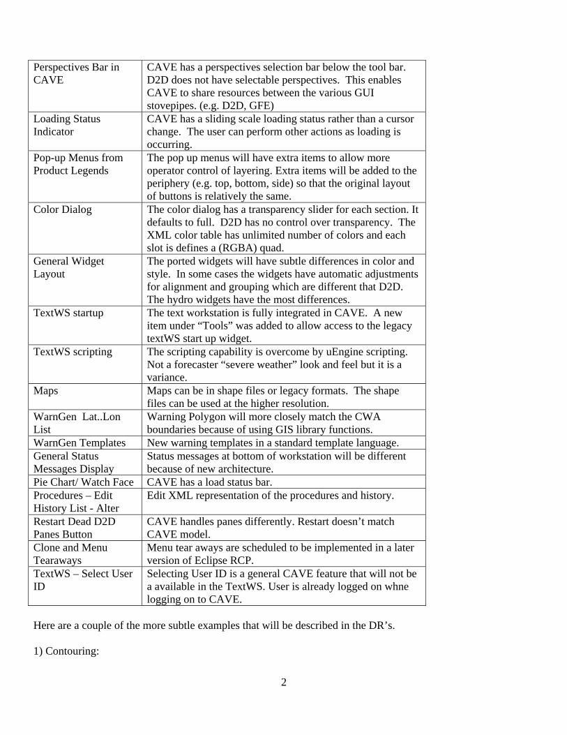
T08 to OB8.1 “black box” variances. The goal for AWIPS II is to retain forecaster look and feel of AWIPS I. This is important several reasons. However, it doesn’t always make sense to mimic the current system exactly. We know several items, if mimicked exactly, would be redone shortly after release 1.0, and, some of these questionable items are costly to mimic. Therefore, we propose to implement the minor deviations in the most cost effect manner with an eye past release 1. Since TO8 is an interim release there should be time to “mimic” if deemed critical after UFE sessions. Our plan is to generate DRs for the functions we are delivering. These DR’s are intended to identify all variances to the exact “black box”. The table below contains some of the more obvious differences. A couple of examples of less obvious differences follow the table. From our perspective many of the items in the table could be considered enhancements, but some people may have a different opinion.
D2D versus CAVE perspective Description
Scale Independent Data can be loaded in any scale. CAVE works at the world scale and bundle definitions create the various zoom windows. D2D scales can be emulated.
Image Combination Buttons
Image combination is superseded by CAVE layering. Each image is a separate controllable layer which enables data interrogation of each layer.
“CAVE” menu item New pull down menu to enable access to new general workstation features. (i.e. ADE volume browser) New items should be added “outside” current layout (i.e. add a button at the end of the menus not in the middle.)
Docked Panes Looping
The docked panes continue looping at the same loop count as the main pane loop control was set for. D2D drops frames.
Selecting SCALES When a new scale is selected the data displayed in the main pane is reprojected to the selected scale. D2D clears the pane.
Creating New Scales User will be able to create new SCALES and save them for later use as bundles. The SCALES can be anywhere and centered anywhere including on the Dateline.
Zoom/Pan differences The main pane has unlimited Zoom in and Pan. Zoom/pan behavior is controlled by bundle settings which the user can change. D2D can be emulated.
2
Perspectives Bar in CAVE
CAVE has a perspectives selection bar below the tool bar. D2D does not have selectable perspectives. This enables CAVE to share resources between the various GUI stovepipes. (e.g. D2D, GFE)
Loading Status Indicator
CAVE has a sliding scale loading status rather than a cursor change. The user can perform other actions as loading is occurring.
Pop-up Menus from Product Legends
The pop up menus will have extra items to allow more operator control of layering. Extra items will be added to the periphery (e.g. top, bottom, side) so that the original layout of buttons is relatively the same.
Color Dialog The color dialog has a transparency slider for each section. It defaults to full. D2D has no control over transparency. The XML color table has unlimited number of colors and each slot is defines a (RGBA) quad.
General Widget Layout
The ported widgets will have subtle differences in color and style. In some cases the widgets have automatic adjustments for alignment and grouping which are different that D2D. The hydro widgets have the most differences.
TextWS startup The text workstation is fully integrated in CAVE. A new item under “Tools” was added to allow access to the legacy textWS start up widget.
TextWS scripting The scripting capability is overcome by uEngine scripting. Not a forecaster “severe weather” look and feel but it is a variance.
Maps Maps can be in shape files or legacy formats. The shape files can be used at the higher resolution.
WarnGen Lat..Lon List
Warning Polygon will more closely match the CWA boundaries because of using GIS library functions.
WarnGen Templates New warning templates in a standard template language. General Status Messages Display
Status messages at bottom of workstation will be different because of new architecture.
Pie Chart/ Watch Face CAVE has a load status bar. Procedures – Edit History List - Alter
Edit XML representation of the procedures and history.
Restart Dead D2D Panes Button
CAVE handles panes differently. Restart doesn’t match CAVE model.
Clone and Menu Tearaways
Menu tear aways are scheduled to be implemented in a later version of Eclipse RCP.
TextWS – Select User ID
Selecting User ID is a general CAVE feature that will not be a available in the TextWS. User is already logged on whne logging on to CAVE.
Here are a couple of the more subtle examples that will be described in the DR’s. 1) Contouring:

3
When data sampling a contour field that has been rendered as an image and interpolation is turned on, the sampling returns the un-interpolated values. D2D returns the interpolated values. The reason for this is CAVE performs image interpolation within the graphics card and D2D interpolates the raw data. Functionally, this is not noticeable until the image is zoomed in enough to become pixilated. Feedback from some weather people is that they prefer CAVE because it returns the real data value not some fudged interpolated value. 2) WarnGen warning by polygon: CAVE generates a lat/lon list for the warning text that is different than D2D. CAVE uses geoTools GIS functions that exactly determine the boundaries of the warning area following the rules for Country Warning Area etc. D2D uses a unique algorithm for determining the lat/lon list that adds unnecessary vertices and the vertices often cross into forbidden areas (i.e. the current implementation is not following the rules precisely.) Functionally, CAVE is following the warning area rules more exactly but will create a warning text product that is slightly different than D2D.