axial flow valves 9710 - · pdf fileamerican meter company can supply copies of these sheets...
TRANSCRIPT
Axial Flow Valves
Installation Instructions and Repair Parts List
www.elster-americanmeter.com

B
AMERICAN METER COMPANY FIVE-YEAR LIMITED WARRANTYIndustrial Regulators
American Meter Company Industrial Products Division (hereinafter referred to as “the Company”) supplies Industrial Regulators of high
quality, materials, and workmanship. The Company will correct any defect(s) of workmanship occurring during the period of one year after
shipment (the “Warranty Start Date”) providing the Purchaser has given the Company immediate written notice of the defects.
In addition, a Five-Year Warranty to the original owner in a permanent regulator installation is offered against structural failure,
and for individual components (list furnished by writing our general offices) from the Warranty Start Date under normal use, operation,
and maintenance.
The Company obligation under this warranty is limited at its option to repayment of the purchase price, repair or furnishing of a similar part
upon inspection and confirmation of the defective condition.
THERE ARE NO OTHER WARRANTIES, EITHER EXPRESSED OR IMPLIED, AND ANY OTHER WARRANTIES ARE HEREBY DISCLAIMED.
A full copy of the American Meter Company Warranty may be obtained by writing our general offices. Laws of the Commonwealth of
Pennsylvania are applicable to this warranty.
WARNINGOUTSIDE Axial Flow Valve installations require that care is taken to prevent pilot vent openings from freezing closed or becoming blocked or
allowing water to enter (from any cause). Particular consideration should be given to sites where flooding, freezing, snow, or freezing rain
may be experienced. Additional overhead protection of the pilot regulator from weather and/or flooding should be used where necessary.
WARNINGAxial Flow Valves are engineered to accurately control natural gas and other approved gases. Axial Flow Valves and all Control System
Components require clean, dry, non-aggressive gases for proper function—gas streams containing liquids, hydrates, hydrogen sulfates,
and other contaminants may shorten Axial Flow Valve and related Control System Components life, and may inhibit proper function.
Please consult your American Meter Company representative if there is a question of compatability of any gas composition, or contact us
through our website: www.americanmeter.com
! !
! !

1
AXIAL FLOW VALVESInterchangeable Valve-Cage Closures ...............................................2The Valve Body.......................................................................................2The Expansible Sleeve ...........................................................................2Trim..........................................................................................................2Bi-Directional Flow Capability ...............................................................2
AXIAL FLOW VALVE OPERATIONControl Passages ..................................................................................3Closed Position ......................................................................................3Throttling .................................................................................................3Open Position .........................................................................................3
VALVE OPERATORSOn-Off .....................................................................................................4Throttling .................................................................................................4Self-Operated .........................................................................................4Controllers ..............................................................................................4
INSPIRATOR CONTROL MANIFOLDManifold for Low Differential Pressures...............................................5Axial Flow Operating Pressures ...........................................................5
CAPACITY LIMITERKit Installation .........................................................................................6Capacity Limiter Removal .....................................................................6Capacity Limiter Kits ..............................................................................6
BASIC CONTROL LOOPSValve Operation .....................................................................................7Valve Downstream Bleed .....................................................................7Pilot Function – Pressure Regulation Service.......................................7Pilot Function – Back Pressure Service .................................................7Restrictor Function and Setting .............................................................7
BASIC CONTROL LOOPS – INSTALLATIONAxial Flow Valve .....................................................................................8
BASIC CONTROL LOOPS – OPERATIONSingle-Stage Pressure-Reducing Regulator ........................................8Two-Stage Pressure Reduction .............................................................9Relief Valve and Back-Pressure Regulation ........................................9Worker/Monitor with Downstream Monitoring ................................ 10Passive Upstream Monitoring .............................................................11Two-Stage Regulation with Monitor Override ................................... 12Pressure-Reducing Regulator with Controller .................................. 13Back-Pressure Regulation with Controller ......................................... 14Internal Manifold Plug Installation Instructions ................................. 15
INSPIRATOR CONTROL MANIFOLDRetrofit Installations ............................................................................. 16New Installations ................................................................................. 16Initial Setup, Single-Stage Pressure Reduction ................................. 16Initial Setup, Worker/Monitor Pressure Reduction ............................ 17Initial Setup, Back Pressure and Relief ............................................... 17Manifold Inspection and Maintenance ............................................. 18Worker Manifold Plug Installation ...................................................... 18
AXIAL FLOW VALVES – MAINTENANCEComponents ........................................................................................ 19Disassembly ........................................................................................ 20Inspection ............................................................................................. 21Reassembly .................................................................................... 21-22Storage ................................................................................................ 22Sleeve Data Stamp ............................................................................. 22
AXIAL FLOW VALVES – REPAIR PARTS AND ACCESSORIESStud Bolts and Nuts-300 Series ......................................................... 23Stud Bolts and Nuts-600 Series ......................................................... 23Accessories ......................................................................................... 23Sizes and Weights .............................................................................. 23Axial Flow Valve 300-Series .............................................................. 24Axial Flow Valve 600-Series .............................................................. 25Control Loop Assemblies ................................................................... 26
Table Of Contents
WARNINGThe standard Buna N sleeve (American Meter codes B5, B5-L and B7) contains no hazardous ingredients that would be considered harmful
to a person handling the sleeve.
However, it has been determined that the surface of the optional hydrin sleeve (American Meter codes H5, H5-L and H7) contains traces of
dioctyl phthalate, a molding agent.
Rubber gloves and an apron should be worn, and you should refrain from eating, drinking and smoking while handling hydrin sleeves.
After handling the hydrin sleeves, the rubber gloves should be washed or discarded, and you should wash your hands thoroughly to
safeguard against the ingestion of the above mentioned chemical.
Additional information is available through American Meter Company in Material Safety Data Sheets for dioctyl phthalate, as produced by
the chemical supplier, before the hydrin sleeve is molded. American Meter Company can supply copies of these sheets to our customers
upon request per the OSHA Hazard Communication Standard.
The information contained herein is based on data available to us and is believed to be correct. However, American Meter company makes
no warranty regarding the accuracy of this data or the results to be obtained from the use thereof. American Meter Company assumes no
responsibility for the injury from the use of this product.
! !
2
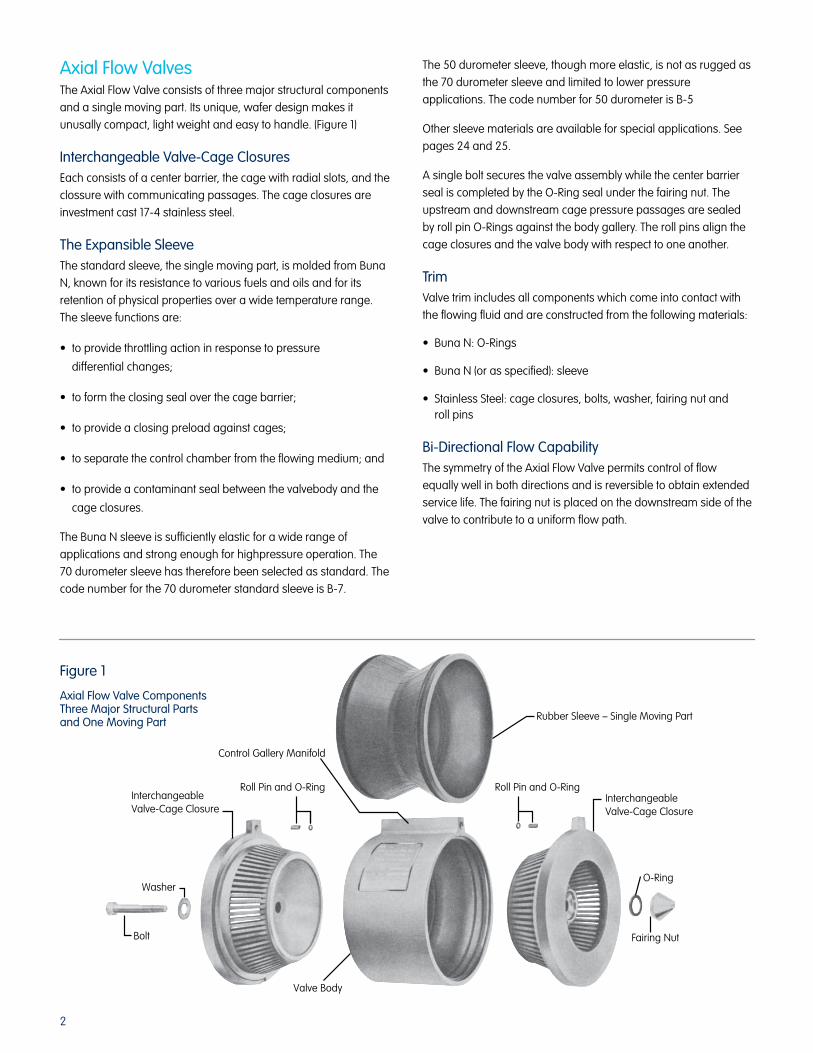
Axial Flow ValvesThe Axial Flow Valve consists of three major structural components
and a single moving part. Its unique, wafer design makes it
unusally compact, light weight and easy to handle. (Figure 1)
Interchangeable Valve-Cage ClosuresEach consists of a center barrier, the cage with radial slots, and the
clossure with communicating passages. The cage closures are
investment cast 17-4 stainless steel.
The Expansible SleeveThe standard sleeve, the single moving part, is molded from Buna
N, known for its resistance to various fuels and oils and for its
retention of physical properties over a wide temperature range.
The sleeve functions are:
• to provide throttling action in response to pressure
differential changes;
• to form the closing seal over the cage barrier;
• to provide a closing preload against cages;
• to separate the control chamber from the flowing medium; and
• to provide a contaminant seal between the valvebody and the
cage closures.
The Buna N sleeve is sufficiently elastic for a wide range of
applications and strong enough for highpressure operation. The
70 durometer sleeve has therefore been selected as standard. The
code number for the 70 durometer standard sleeve is B-7.
The 50 durometer sleeve, though more elastic, is not as rugged as
the 70 durometer sleeve and limited to lower pressure
applications. The code number for 50 durometer is B-5
Other sleeve materials are available for special applications. See
pages 24 and 25.
A single bolt secures the valve assembly while the center barrier
seal is completed by the O-Ring seal under the fairing nut. The
upstream and downstream cage pressure passages are sealed
by roll pin O-Rings against the body gallery. The roll pins align the
cage closures and the valve body with respect to one another.
TrimValve trim includes all components which come into contact with
the flowing fluid and are constructed from the following materials:
• BunaN:O-Rings
• BunaN(orasspecified):sleeve
• StainlessSteel:cageclosures,bolts,washer,fairingnutand roll pins
Bi-Directional Flow CapabilityThe symmetry of the Axial Flow Valve permits control of flow
equally well in both directions and is reversible to obtain extended
service life. The fairing nut is placed on the downstream side of the
valve to contribute to a uniform flow path.
Rubber Sleeve – Single Moving Part
Roll Pin and O-RingInterchangeableValve-Cage Closure
O-Ring
Fairing Nut
Valve Body
Bolt
Washer
Control Gallery Manifold
InterchangeableValve-Cage Closure
Roll Pin and O-Ring
Figure 1
Axial Flow Valve Components Three Major Structural Parts and One Moving Part

3
Axial Flow Valve – OperationControl Passages (Figure 2)The gallery of the valve body has three passages:
1. The inlet pressure normally supplies the control pressure. The
inlet supply pressure passage is in the upstream closure and
connects with the gallery.
2. The control passage branches into two annular grooves in the
valve body. The annular grooves distribute control pressure
around the sleeve when the sleeve is in the fully open or
closed position.
3. The exhaust or downstream bleed passage is normally used
to permit reduction in control pressure when opening the
valve. The aspirating capability of this passage insures a fully
expanded sleeve with minimal pressure differential.
Closed Position (Figure 3)The sleeve is molded to a smaller diameter than the cage
diameter. When assembled in the valve, the sleeve exerts a closing
preload on the upstream and downstream cages. The
inner upstream surface of the sleeve is exposed to inlet
pressure applied.
Control pressure (supplied by and equal to the inlet pressure) is
against the exterior of the sleeve. The differential pressure on the
upstream portion of the sleeve is 0 psi, but the sleeve preload
exerts a closing force. The differential across the downstream
portion of sleeve is the difference between the upstream and
downstream presures. This differential plus the sleeve preload
provides the closing force.
Throttling (Figure 4)To open the valve, control pressure must be reduced. A small
decrease in the control pressure permits inlet pressure to lift the
sleeve from the inlet cage. As the control pressure is further
decreased, the central sleeve preload is overcome and the sleeve
is peeled progressively away from the downstream cage. Flow
through the valve commences when the tapered openings of the
outlet cage are uncovered. Further decreases in control pressure
uncover a greater area of the outlet cage. Throttling control is
maintained when the control pressure reaches equilibrium and
flow demand is satisfied.
Open Position (Figure 5)The valve is fully open when the drop in control pressure is
sufficient to completely expose the slots in the downstream cage,
and the sleeve is fully expanded against the body inner contour.
The control pressure drop is aided by aspiration through the
downstream bleed aspiration port. At high rates of flow, the
aspirated pressure in the bleed channel can be significantly lower
than the downstream pipe line pressure, thereby minimizing the
differential between inlet and outlet pressures required for full
valve opening.Figure 2
ControlPressure Exhaust
Downstream Bleed
Flow
Flow
InletSupply
Pressure
ControlGalley
Downstream Cage
OutletPressure
DownstreamCage
UpstreamCage
UpstreamCage
InletPressure
CenterBarrier
BodySleeve
ControlPressure
Cage
InletPressure
Exhaust orDownstreamBleed
Sleeve
Cage
Sleeve
Cage
Sleeve
ControlPressure
InletPressure
Exhaust orDownstreamBleed
ControlPressure
InletPressure
Exhaust orDownstreamBleed
Axial Flow Valve ComponentsThree Major Structural Parts and One Moving Part
Figure 4Throttling Position
Figure 3Closed Position
Figure 5Open Position

4
Valve Operators (Figure 6)The Axial Flow Valve is essentially a pneumatic or hydraulic
motor valve. To function, the basic valve requires some type of a
valve operator.
The Axial Flow Valve is normally closed (if control and inlet pressure
are equal). When closed, the closing forces are control chamber
pressure acting on the sleeve exterior plus the elastic preload. The
opening forces are inlet pressure acting on the interior of the
sleeve through the inlet cage. To crack the valve, control pressure
must be decreased so that inlet pressure can overcome the initial
preload. To open the valve further, control pressure must be
reduced. To open the valve fully, control pressure must be reduced
until inlet pressure has fully expanded the sleeve. Any further
reduction of control pressures does not affect the valve operation.
See page 5 for table of operating pressures.
To change the control chamber pressure, two external valves
are required.
Valve A controls the supply pressure. Usually, inlet pressure is used
to supply control chamber pressure. Control chamber pressure
closes the valve. In the majority of application, Valve A is an
adjustable, non-closing restrictor.
Valve B adjusts control chamber pressure and positions the
sleeve. Valve B is usually a pilot pressure regulator. A three-way
connector is required to make connections to Valve A, Valve B
and to control chamber.
On-OffFor On-Off applications, an adjustable restrictor is used for Valve A,
and Valve B can be open or closed.
Manually – by means of handler buttons, levers or foot pedals;
Automatically – by means of electrical operated solenoids,
mechanically operated lever or cams and motors.
ThrottlingThrottling applications require the feedback of pressure which is
utilized in controlling the position of Valve B.
Self-OperatedSelf-operated applications are used in pressure control. Sensed
pressure (downstream) is used for pressure reducing regulation.
Sensed pressure (upstream) is used for relief valve and back
pressure service.
ControllersControllers are used when precision control is required for severe
operating conditions. Many combinations of pilots and pneumatic
controllers can be used for flow, pressure, temperature, or process
control. A controller does not normally act directly to position the
sleeve but rather must act through a “pilot” or diaphragm motor
valve interface.
Valve BOpen
Valve AClose
InletSupply
Pressure
UpstreamCage
DownstreamCage
ControlGalley
Control PressureExhaust orDownstram Bleed
DownstreamCage
OutletPressure
InletPressure
P2P1
UpstreamCage
Sleeve
CenterBarrier
Pc
Body
Reduced ControlPort Pressure OPENSAxial Flow Valve
Figure 6
Axial Flow Valve with Manual Operator
5
Inspirator Control ManifoldManifold For Low Differential PressureWhen equipped with an optional Inspirator Control Manifold, the
American Axial FlowTM Valve provides accurate and proven
pressure regulation in applications with very low differential
pressures. The manifold extends the operating range of the AFV at
low inlet pressures while maintaining the same maximum
operating pressure ratings.
The Axial Flow Valve uses an elastomer sleeve which expands or
contracts depending on the pressure differential across the sleeve.
Once this differential exceeds the minimum cracking pressure,
the sleeve expands allowing flow through the valve until
downstream demand is supplied and the pressure is balanced
across the sleeve.
With a conventional restrictor-type control manifold, the sleeve
differential pressure cannot be greater than the total pressure drop
across the valve. In some peak load applications, the inlet pressure
can be reduced to the point where there is not a sufficient
differential between the inlet and the outlet (set) pressure to allow
the valve to fully open. Or, in high-pressure applications, the
differential needed to fully open the valve may be greater than the
available drop across the valve.
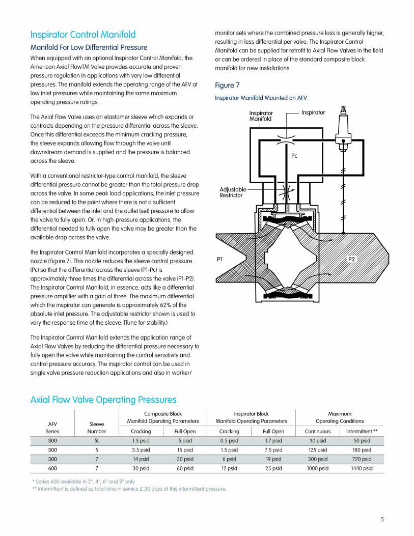
the Inspirator Control Manifold incorporates a specially designed
nozzle (Figure 7). This nozzle reduces the sleeve control pressure
(Pc) so that the differential across the sleeve (P1-Pc) is
approximately three times the differential across the valve (P1-P2).
The Inspirator Control Manifold, in essence, acts like a differential
pressure amplifier with a gain of three. The maximum differential
which the inspirator can generate is approximately 62% of the
absolute inlet pressure. The adjustable restrictor shown is used to
vary the response time of the sleeve. (Tune for stability.)
The Inspirator Control Manifold extends the application range of
Axial Flow Valves by reducing the differential pressure necessary to
fully open the valve while maintaining the control sensitivity and
control pressure accuracy. The inspirator control can be used in
single valve pressure reduction applications and also in worker/
monitor sets where the combined pressure loss is generally higher,
resulting in less differential per valve. The Inspirator Control
Manifold can be supplied for retrofit to Axial Flow Valves in the field
or can be ordered in place of the standard composite block
manifold for new installations.
AFV Series
Sleeve Number
Composite BlockManifold Operating Parameters
Inspirator BlockManifold Operating Parameters
MaximumOperating Conditions
Cracking Full Open Cracking Full Open Continuous Intermittent **
300 5L 1.5 psid 5 psid 0.5 psid 1.7 psid 30 psid 50 psid
300 5 3.5 psid 15 psid 1.5 psid 7.5 psid 125 psid 180 psid
300 7 14 psid 30 psid 6 psid 19 psid 500 psid 720 psid
600 7 30 psid 60 psid 12 psid 25 psid 1000 psid 1440 psid
* Series 600 available in 2", 4", 6" and 8" only.** Intermittent is defined as total time in service £ 30 days at this intermittent pressure.
Axial Flow Valve Operating Pressures
InspiratorManifold
Inspirator
Pc
AdjustableRestrictor
P1 P2
Figure 7
Inspirator Manifold Mounted on AFV
6
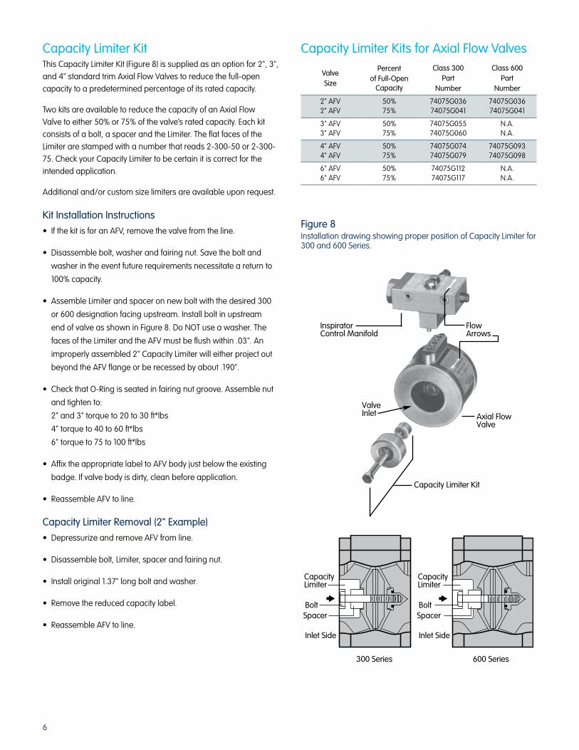
Capacity Limiter KitThis Capacity Limiter Kit (Figure 8) is supplied as an option for 2", 3",
and 4" standard trim Axial Flow Valves to reduce the full-open
capacity to a predetermined percentage of its rated capacity.
Two kits are available to reduce the capacity of an Axial Flow
Valve to either 50% or 75% of the valve’s rated capacity. Each kit
consists of a bolt, a spacer and the Limiter. The flat faces of the
Limiter are stamped with a number that reads 2-300-50 or 2-300-
75. Check your Capacity Limiter to be certain it is correct for the
intended application.
Additional and/or custom size limiters are available upon request.
Kit Installation Instructions
• If the kit is for an AFV, remove the valve from the line.
• Disassemble bolt, washer and fairing nut. Save the bolt and
washer in the event future requirements necessitate a return to
100% capacity.
• Assemble Limiter and spacer on new bolt with the desired 300
or 600 designation facing upstream. Install bolt in upstream
end of valve as shown in Figure 8. Do NOT use a washer. The
faces of the Limiter and the AFV must be flush within .03". An
improperly assembled 2" Capacity Limiter will either project out
beyond the AFV flange or be recessed by about .190".
• Check that O-Ring is seated in fairing nut groove. Assemble nut
and tighten to:
2" and 3" torque to 20 to 30 ft*lbs
4" torque to 40 to 60 ft*lbs
6" torque to 75 to 100 ft*lbs
• Affix the appropriate label to AFV body just below the existing
badge. If valve body is dirty, clean before application.
• Reassemble AFV to line.
Capacity Limiter Removal (2" Example)
• Depressurize and remove AFV from line.
• Disassemble bolt, Limiter, spacer and fairing nut.
• Install original 1.37" long bolt and washer.
• Remove the reduced capacity label.
• Reassemble AFV to line.
Valve Size
Percent of Full-Open
Capacity
Class 300 Part
Number
Class 600 Part
Number
2" AFV2" AFV
50%75%
74075G03674075G041
74075G03674075G041
3" AFV3" AFV
50%75%
74075G05574075G060
N.A.N.A.
4" AFV4" AFV
50%75%
74075G07474075G079
74075G09374075G098
6" AFV6" AFV
50%75%
74075G11274075G117
N.A.N.A.
Capacity Limiter Kits for Axial Flow Valves
InspiratorControl Manifold
Flow Arrows
ValveInlet Axial Flow
Valve
Capacity Limiter Kit
600 Series300 Series
CapacityLimiter
BoltSpacer
Inlet Side
CapacityLimiter
BoltSpacer
Inlet Side
Figure 8Installation drawing showing proper position of Capacity Limiter for 300 and 600 Series.

7
Exhaust -DownstreamBleed
DownstreamStatic SensingLine
Downstream Cage
BodySleeve
Upstream Cage
AdjustableRestrictor
FilterElementINLETSUPPLYPRESSURE
CONTROLPRESSURE
OUTLETPRESSURE
CenterBarrier
Axial Flow Valve – Valve OperationThe valve is closed when the pilot regulator is closed and the
upstream pressure has equalized through the restrictor acting
against the exterior of the sleeve as a valve closing force.
• The valve is closed when the control pressure is equal to the
inlet pressure.
• The valve begins to open when there is a reduction in control
pressure which is greater than the sleeve preload.
• The valve is fully open when the drop in control pressure
is sufficient to permit inlet pressure to completely expand
the sleeve.
Valve Downstream BleedThe valve downstream bleed on the AFV is aspirated at high rates
of flow by a venturi effect. This aspiration induces a drop in
pressure in the valve downstream port. The induced drop in
pressure aids the pilot to lower the control pressure when the valve
approaches full open.
Do not use the AFV downstream bleed port for pressure sensing. A
stable pressure location MUST be used for feedback to the pilot.
For pressure regulation, the pilot senses downstream pressure. A
demand for flow will slightly reduce downstream pressure and will
open the pilot valve. The effective opening of the pilot valve is
regulated by changes in the downstream pressure sensed.
Pilot Function – Back Pressure Service and Relief Valve Operation (RV)
(Figure 11)
For back-pressure regulation and relief-valve operation, the pilot
senses upstream pressure. An increase in upstream pressure
above the dead-end shut-off† pressure causes the pilot valve to
open and exhaust control pressure.
The effective opening of the pilot valve is regulated by upstream
pressure changes sensed.
Adjustable Restrictor Function and SettingThe adjustable restrictor supplies makeup gas to the AFV control
port in opposition to the gas bled away by the pilot regulator (or
motor valve). Standard composite block settings are typically “3”.
Inspirator Block Settings are typically 5-6. (Careful tuning is required
for good control and stability.)
† Dead-end shut off in this application is called relief pressure setting.
Basic AFV Control LoopsRefer to Figures 9, 10, 11
DownstreamStatic Sense LineConnection
Pilot Vent
Inlet Pilot Supply(Pressure Connection)
Pilot Return Line to Downstream
Pilot Vent
Inlet Pilot Supply(Pressure Connection)
DownstreamStatic Sense LineConnection
Pilot ReturnLine to Downstream
Figure 9
COMPOSITE Block Manifold Connections
Figure 9
INSPIRATOR Manifold Connections
Pilot Function – Pressure Reduction Service (PR)
(Figure 10)
Exhaust -DownstreamBleed
Downstream Cage
BodySleeve
Upstream Cage
AdjustableRestrictor
UpstreamStaticSensingLine
FilterElementINLETSUPPLYPRESSURE
CONTROLPRESSURE
OUTLETPRESSURE
CenterBarrier

8
Pilot
Restrictor (Upstram)Composite Manifold Block
"O" Rings
Gasket
+ PositionsFlange
Separators
FLOWFLOW
Nut
Nut
Flange Separator(Two required)
Centering TubesUsed with ANSI 250and 300 flange
Stud Bolts
Gasket(Customer supplied)
Flaring Nut(Downstream)
Axial Flow Valve
Static PressureConnections
Mounting Screws
Installation (Figure 12)1. Assemble the control loop as indicated below (Figure 12) with
restrictor inlet position at the upstream of the Axial Flow Valve.
2. The Control Loop assembly may be mounted on the smaller AFVs before the valve is mounted between the pipe flanges. Three O-Rings are required. (Six with Inspirator) The O-Rings slip on the roll pins which align the ports in the composite manifold with the ports in the Axial Flow Valve gallery.
Larger Axial Flow Valves should be mounted between the pipe flanges before the control loop is mounted on the Axial Flow Valve.
To facilitate the handling of heavier valves, a lifting plate, Part Number 73672P001, is available. The lifting plate is attached to the gallery on the valve body with the composite manifold mounting screws and has a lifting opening (1/2" x 1-1/2") which is suitable for engagement by a hook or cable.
3. Align the pipe flanges and insert the lower stud bolts. Optional centering tubes can be placed over the two lowest stud bolts for the 250 and 300 ANSI flange installations.
4. If the pull-up space is less than desired, use the flange separators to increase the space. The Axial Flow Valve must be installed with its fairing nut on downstream side of the valve. Place the valve and gaskets between the flange. Place the nuts on the stud bolts.
5. Remove the flange separators (if used). Tighten the nuts evenly around the bolt circle. Assure that a minimum of one and one-half or more threads show beyond the nut.
6. Check the control loop and system for leads to assure all the connections are tightened properly and that no tubing has been nicked or bent.
AFV with Composite Block ControlSingle-Stage Pressure-Reducing (PR) Regulator (Figure 13)
1. Set restrictor to maximum (No. 8) setting.
2. Relax pressure spring of pilot regulator by backing out adjustment screw until spring tension is at minimum.
3. Crack downstream block valve.
4. Crack upstream block valve to pressurize Axial Flow Valve (AFV).
5. Fully open upstream and downstream block valves.
6. Slowly increase pilot pressure spring tension until some downstream flow is achieved.
7. Reset restrictor (slowly) to No. 4 setting.
8. Slowly increase pilot pressure spring tension until downstream pressure approximates desired set pressure.
9. Tune system by alternately adjusting the pilot pressure spring and restrictor until both the required set point and stable control is achieved at the lowest possible restrictor setting under normal flow conditions.
10. Slowly close downstream block valve to check for AFV lockup.
11. Gradually open downstream block valve.
NOTE: The Composite Block adjustable restrictor controls the rate of AFV opening and closing. Low restrictor settings quicken the opening and slow the closing. Restrictor settings above 4 tend to flood the control system; therefore, high settings should be avoided unless required for control stability. Composite Block restrictor settings of 2 or 3 are normal under most conditions. (Inspirator Block restrictor should be set at 5-6.)
AdjustableRestrictor
AdjustableRestrictor
Block Valve
Block Valve
Block Valve
Block Valve
Axial Flow Valve
Axial Flow Valve
PilotPilotAdjust Screw
StaticPilot
PilotAdjust Screw
Pilot With Secondary Diaph.60 Series Pilot
Pilot W/O Secondary Diaph.1203
Figure 12
AFV and Control Loop (typical)

9
1. Set restrictors of both first- and second-stage regulators to maximum (No. 8) setting.
2. Relax the pressure spring of both pilot regulators by backing out adjustment screw until spring tension is at minimum.
3. Crack downstream block valve.
4. Crack upstream block valve to pressurize Axial Flow Valve (AFV).
5. Fully open upstream and downstream block valves.
6. Slowly increase pilot pressure spring tension of first-stage until approximate desired intermediate pressure is indicated to inlet of second stage.
7. Slowly reset first-stage restrictor to No. 4 setting.
8. Slowly increase pilot pressure spring tension of second-stage regulator until approximate downstream pressure is achieved.
9. Gradually reset second-stage restrictor to No. 4 setting.
10. Tune first-stage regulator by alternately adjusting the pilot pressure spring and restrictor until both the required set point and stable control is achieved at the lowest possible restrictor setting under normal flow conditions.
11. Tune second-stage regulator in same manner.
12. Close downstream block valve to check for AFV lockup.
13. Gradually open downstream block valve.
NOTE: The Composite Block adjustable restrictor controls the rate of AFV opening and closing. Low restrictor settings quicken the opening and slow the closing. Restrictor settings above 4 tend toflood the control system; therefore, high settings should be avoided unless required for control stability. Composite Block restrictor settings of 2 or 3 are normal under most conditions. (Inspirator Block restrictor should be set at 5-6.)
1. Set restrictor to maximum (No. 8) setting.
2. Increase pressure spring tension of pilot regulator by turning adjusting screw inward until maximum tension is attained.
3. Open downstream block valve (if used).
4. Gradually introduce inlet pressure to the AFV
5. Gradually decrease pilot pressure spring tension until: Back pressure – some downstream flow is achieved Relief valve – the desired set point is reached.
6. Reset restrictor to: Back pressure – No. 4 setting Relief valve – the correct restrictor setting is determined at time of installation. Use the lowest restrictor setting which permits the Axial Flow Valve to reseat at a pressure greater than the normal line pressure. Settings from No. 3 to No. 4 are normal.
7. Back pressure only – slowly decrease pilot-pressure spring tension until upstream pressure approximates desired set pressure.
8. Back pressure only – tune system by alternately adjusting the pilot pressure spring and restrictor until both required set point and stable control is achieved at the lowest possible restrictor setting under normal flow conditions.
NOTE: The Composite Block adjustable restrictor controls the rate of AFV opening and closing. Low restrictor settings quicken the opening and slow the closing. Restrictor settings above 4 tend to flood the control system; therefore, high settings should be avoided unless required for control stability. Composite Block restrictor settings of 2 or 3 are normal under most conditions. (Inspirator Block restrictor should be set at 5-6.)
Pilot PilotAdjustable Screw
Pilot
AdjustableRestrictor
Block Valve
Block Valve 1st Stage
Regulator2nd StageRegulator
Static
AdjustableRestrictor
PilotAdustable Screw
Axial Flow Valve
AdjustableRestrictor
Block Valve
Block Valve
PilotAdjustableScrew
Pilot
Static
AFV with Composite Block ControlTwo-Stage Pressure Reduction (PR) (Figure 14)
AFV with Composite Block ControlRelief Valve (RV) and Back-Pressure Regulation (Figure 15)

10
AFV with Composite Block Control Worker/Monitor with Downstream Monitoring(Figure 16)
1. Set restrictors of both worker and monitor to maximum (No. 8) setting.
2. Relax pressure spring of monitor pilot regulator by backing out the adjustment screw until spring tension is at minimum.
3. Increase pressure spring tension of worker pilot regulator to maximum by turning adjusting screw inward.
4. Crack downstream valve slightly open.
5. Slowly crack upstream block valve open to pressurize Axial Flow Valves.
6. Fully open upstream and downstream block valves.
7. Reset monitor restrictor to No. 4 setting.
8. Reset worker restrictor to No. 2 setting.
9. Slowly increase monitor pilot pressure spring tension until downstream pressure approximates desired monitor set pressure.
NOTE: See table below of suggested monitor/regulator set point differentials.
Set Pressure Differentials
Working Regulator Set Points Monitor Regulator Set Points
8" w.c. to 28" w.c. 2" to 5" w.c. above worker
1 psig to 5 psig 1/4 to 3/4 psig above worker
5 psig to 10 psig 1/2 to 1 psig above worker
10 psig to 30 psig 1 to 2 psig above worker
30 psig – Up 5% of maximum adjustment above worker set pressure
10. Tune monitor by alternately adjusting the pilot pressure spring and restrictor until both the required set point and stable control are achieved at the lowest possible restrictor setting under normal flow conditions.
11. Reset worker restrictor to No. 4 setting.
12. Slowly decrease worker pilot pressure spring tension until worker regulator assumes control and the downstream pressure approximates desired worker set pressure.
13. Tune worker in same manner as outlined in Step 10.
14. Close downstream block valve to check for AFV lockup.
15. Gradually open downstream block valve.
** See Internal Plug Installation, Figure 21 on page 15.
NOTE: The Composite Block adjustable restrictor controls the rate of AFV opening and closing. Low restrictor settings quicken the opening and slow the closing. Restrictor settings above 4 tend to flood the control system; therefore, high settings should be avoided unless required for control stability. Composite Block restrictor settings of 2 or 3 are normal under most conditions. (Inspirator Block restrictor should be set at 5-6.)
PilotAdjustScrew
PilotAdjustScrew
BlockValve
BlockValve
* InternalPlug
MonitorAFV
WorkerAFV
AdjustableRestrictor Adjustable
Restrictor
MonitorStatic
WorkerStatic
Pilot

11
AFV with Composite Block Control Worker/Monitor with Passive Upstream Monitoring ((Figure 17)
Setting Worker in Service
1. Set restrictors of both worker and monitor to maximum No. 8 setting.
2. Relax pressure spring of worker pilot regulator by backing out the adjustment screw until spring tension is at minimum.
3. Increase pressure spring tension of monitor pilot to maximum by turning adjusting screw inward.
4. Crack downstream valve slightly open.
5. Slowly crack upstream block valve to pressurize Axial Flow Valve (AFV).
6. Fully open upstream and downstream block valves.
7. Reset monitor restrictor to No. 2.
8. Slowly increase pilot pressure spring tension of worker until some downstream flow is achieved.
9. Slowly reset worker restrictor less than No. 4 setting.
10. Slowly increase worker pilot pressure spring tension until downstream pressure approximates desired worker set pressure.
11. Tune AFV worker by alternately adjusting the pilot pressure spring and restrictor until both the required set point and stable control are achieved at the lowest possible restrictor setting under normal flow conditions.
Set Pressure Differentials
Working Regulator Set Points Monitor Regulator Set Points
8" w.c. to 28" w.c. 2" to 5" w.c. above worker
1 psig to 5 psig 1/4 to 3/4 psig above worker
5 psig to 10 psig 1/2 to 1 psig above worker
10 psig to 30 psig 1 to 2 psig above worker
30 psig – Up 5% of maximum adjustment above worker set pressure
*
PilotAdjustScrew
PilotAdjustScrew
BlockValve
BlockValve
* InternalPlug
WorkerAFV
MonitorAFV
AdjustableRestrictor Adjustable
Restrictor
MonitorStatic
MonitorStatic
Pilot
Setting Monitor in Service
1. Slowly decrease monitor pilot pressure spring tension until it begins to assume control from the worker.
2. Fail worker wide open by disconnecting sense line or increasing set point above desired monitor set pressure.
3. Tune monitor by alternately adjusting pilot pressure spring and restrictor until both the required set point and stable control is achieved at the lowest possible restrictor setting under normal flow conditions.
4. Place worker back in operation by reversing action Step 2 above.
5. Close downstream block valve to check for AFV lockup.
6. Gradually open downstream block valve.
7. Reset monitor restrictor to No. 2.
NOTE: The Composite Block adjustable restrictor controls the rate of AFV opening and closing. Low restrictor settings quicken the opening and slow the closing. Restrictor settings above 4 tend to flood the control system; therefore, high settings should be avoided unless required for control stability. Composite Block restrictor settings of 2 or 3 are normal under most conditions. (Inspirator Block restrictor should be set at 5-6.)
12
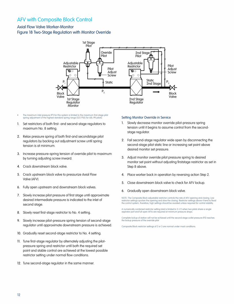
AFV with Composite Block ControlAxial Flow Valve Worker-MonitorFigure 18 Two-Stage Regulation with Monitor Override
• Themaximuminletpressure(P1)forthissystemislimitedtothemaximumfirst-stagepilotspring adjustment of the highest standard spring range (325 PSIG for 60L-PR pilots).
1. Set restrictors of both first- and second-stage regulators to maximum No. 8 setting.
2. Relax pressure spring of both first-and secondstage pilot regulators by backing out adjustment screw until spring tension is at minimum.
3. Increase pressure-spring tension of override pilot to maximum by turning adjusting screw inward.
4. Crack downstream block valve.
5. Crack upstream block valve to pressurize Axial Flow Valve (AFV).
6. Fully open upstream and downstream block valves.
7. Slowly increase pilot pressure of first stage until approximate desired intermediate pressure is indicated to the inlet of second stage.
8. Slowly reset first-stage restrictor to No. 4 setting.
9. Slowly increase pilot-pressure spring tension of second-stage regulator until approximate downstream pressure is achieved.
10. Gradually reset second-stage restrictor to No. 4 setting.
11. Tune first-stage regulator by alternately adjusting the pilot-pressure spring and restrictor until both the required set point and stable control are achieved at the lowest possible restrictor setting under normal flow conditions.
12. Tune second-stage regulator in the same manner.
Setting Monitor Override in Service
1. Slowly decrease monitor override pilot-pressure spring tension until it begins to assume control from the second- stage regulator.
2. Fail second-stage regulator wide open by disconnecting the second-stage pilot static line or increasing set point above desired monitor set pressure.
3. Adjust monitor override pilot pressure spring to desired monitor set point without adjusting firststage restrictor as set in Step 8 above.
4. Place worker back in operation by reversing action Step 2.
5. Close downstream block valve to check for AFV lockup.
6. Gradually open downstream block valve.
NOTE: The Composite Block adjustable restrictor controls the rate of AFV opening and closing. Low restrictor settings quicken the opening and slow the closing. Restrictor settings above 4 tend to flood the control system; therefore, high settings should be avoided unless required for control stability.
A numerically combined restrictor setting total is limited to 3-1/2 when two pilots share a single aspirator port and full open AFVs are required at minimum pressure drops.
Complete lockup of station will not be achieved until the second stage outlet pressure (P2) reaches the lockup pressure of the override pilot
Composite Block restrictor settings of 2 or 3 are normal under most conditions.
BlockValve
BlockValve
2nd StageRegulator
1st StageRegulatorMonitor
P2
Static
PilotAdjustScrew
PilotAdjustScrew
1st StagePilot
OveridePilot
2nd StagePilot
AdjustableRestrictor
AdjustableRestrictor
Static2nd Stage P3
P1
13
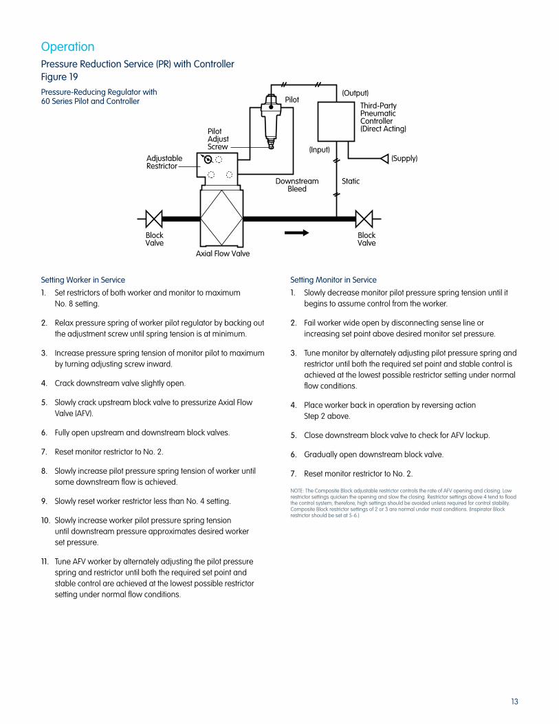
OperationPressure Reduction Service (PR) with ControllerFigure 19
Pressure-Reducing Regulator with60 Series Pilot and Controller
Setting Worker in Service
1. Set restrictors of both worker and monitor to maximum No. 8 setting.
2. Relax pressure spring of worker pilot regulator by backing out the adjustment screw until spring tension is at minimum.
3. Increase pressure spring tension of monitor pilot to maximum by turning adjusting screw inward.
4. Crack downstream valve slightly open.
5. Slowly crack upstream block valve to pressurize Axial Flow Valve (AFV).
6. Fully open upstream and downstream block valves.
7. Reset monitor restrictor to No. 2.
8. Slowly increase pilot pressure spring tension of worker until some downstream flow is achieved.
9. Slowly reset worker restrictor less than No. 4 setting.
10. Slowly increase worker pilot pressure spring tension until downstream pressure approximates desired worker set pressure.
11. Tune AFV worker by alternately adjusting the pilot pressure spring and restrictor until both the required set point and stable control are achieved at the lowest possible restrictor setting under normal flow conditions.
Setting Monitor in Service
1. Slowly decrease monitor pilot pressure spring tension until it begins to assume control from the worker.
2. Fail worker wide open by disconnecting sense line or increasing set point above desired monitor set pressure.
3. Tune monitor by alternately adjusting pilot pressure spring and restrictor until both the required set point and stable control is achieved at the lowest possible restrictor setting under normal flow conditions.
4. Place worker back in operation by reversing action Step 2 above.
5. Close downstream block valve to check for AFV lockup.
6. Gradually open downstream block valve.
7. Reset monitor restrictor to No. 2.
NOTE: The Composite Block adjustable restrictor controls the rate of AFV opening and closing. Low restrictor settings quicken the opening and slow the closing. Restrictor settings above 4 tend to flood the control system; therefore, high settings should be avoided unless required for control stability. Composite Block restrictor settings of 2 or 3 are normal under most conditions. (Inspirator Block restrictor should be set at 5-6.)
Pilot
(Input)
Static
(Supply)
(Output)
BlockValve
BlockValve
Axial Flow Valve
AdjustableRestrictor
PilotAdjustScrew
DownstreamBleed
Third-PartyPneumaticController(Direct Acting)
14
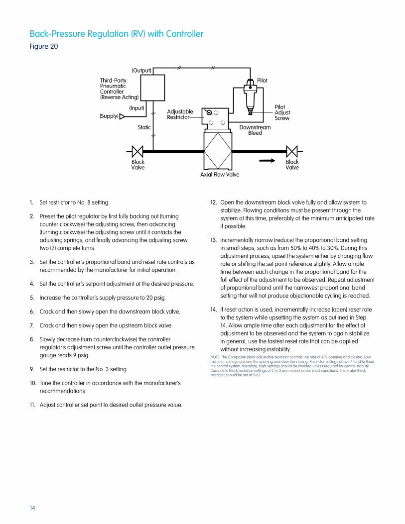
Back-Pressure Regulation (RV) with ControllerFigure 20
1. Set restrictor to No. 8 setting.
2. Preset the pilot regulator by first fully backing out (turning counter clockwise) the adjusting screw, then advancing (turning clockwise) the adjusting screw until it contacts the adjusting springs, and finally advancing the adjusting screw two (2) complete turns.
3. Set the controller’s proportional band and reset rate controls as recommended by the manufacturer for initial operation.
4. Set the controller’s setpoint adjustment at the desired pressure.
5. Increase the controller’s supply pressure to 20 psig.
6. Crack and then slowly open the downstream block valve.
7. Crack and then slowly open the upstream block valve.
8. Slowly decrease (turn counterclockwise) the controller regulator’s adjustment screw until the controller outlet pressure gauge reads 9 psig.
9. Set the restrictor to the No. 3 setting.
10. Tune the controller in accordance with the manufacturer’s recommendations.
11. Adjust controller set point to desired outlet pressure value.
12. Open the downstream block valve fully and allow system to stabilize. Flowing conditions must be present through the system at this time, preferably at the minimum anticipated rate if possible.
13. Incrementally narrow (reduce) the proportional band setting in small steps, such as from 50% to 40% to 30%. During this adjustment process, upset the system either by changing flow rate or shifting the set point reference slightly. Allow ample time between each change in the proportional band for the full effect of the adjustment to be observed. Repeat adjustment of proportional band until the narrowest proportional band setting that will not produce objectionable cycling is reached.
14. If reset action is used, incrementally increase (open) reset rate to the system while upsetting the system as outlined in Step 14. Allow ample time after each adjustment for the effect of adjustment to be observed and the system to again stabilize. In general, use the fastest reset rate that can be applied without increasing instability.
NOTE: The Composite Block adjustable restrictor controls the rate of AFV opening and closing. Low restrictor settings quicken the opening and slow the closing. Restrictor settings above 4 tend to flood the control system; therefore, high settings should be avoided unless required for control stability. Composite Block restrictor settings of 2 or 3 are normal under most conditions. (Inspirator Block restrictor should be set at 5-6.)
Pilot
(Output)
(Supply)
Third-PartyPneumaticController(Reverse Acting)
(Input)AdjustableRestrictor
DownstreamBleed
Axial Flow Valve
BlockValve
BlockValve
Static
PilotAdjustScrew

15
MAX
MIN
VENT
IN
O-RingsInternalManifoldPlug
O-Ring
AxialFlowValve
FLOW
Internal PressureSupply
INTERNAL SCREWPLUG
ExternalPressureSupply Port
Hex-HeadCap ScrewInspirator
Block
RestrictorBlock
ControlLoop
AxialFlowValve
AFV Composite and Inspirator Control BlockUse of Control Block Plug KitsInternal Manifold PlugFigure 21 – Installation InstructionsComposite Block
Downstream monitoring and passive upstream monitoring
applications require the use of an internal inlet plug to block the
pilot supply and to prevent pressure build-up in the intermediate
pipiing between the two Axial Flow Valves. This plug is available as
a retrofit kit; order Kit No. 74036K001. (Composite Block)
NOTE: The internal manifold plug must be used in the downstream valve only.
1. Depressurize system, remove two hex-head cap screws and separate the Block from the AFV.
2. The Composite Block control loop normally has three (3) roll pins pressed into the manifold at the gallery interface surface. Remove the roll pin at the inlet port with a pair of pliers.
3. Spread a small amount of silicone grease or petroleum jelly over the O-Ring and wipe so that the ring is covered with a thin film of lubricant.
4. Carefully slide the O-Ring over the plug and into the O-Ring groove machined into the plug.
5. Inspect the inlet port in the AFV gallery and remove all water or solid debris.
6. Slide the plug into this port so that the O-Ring is completely covered by the port in the gallery.
7. The plug will protrude from the gallery.
8. Reassemble the control loop to the gallery after visually inspecting the O-Rings that fit into the grooves in the manifold around the roll pins.
9. CAUTION: The plug must also be inserted into one of the O-Rings mentioned in Step 7, or a joint leak will result. (NOTE: two O-Rings in Figure 21.)
10. Establish pressure supply to the AFV and inspect the joint between the gallery and manifold block for leaks, using a soap solution in warm water or removing the valve from the site to a heated building and test with air in cold-weather environments.
1. Use 74036K002 Plug Kits to block off Inspirator Block inlet ports.
2. Depressurize system, remove two hex-head cap screws and separate the Inspirator Block from the Restrictor Block. Do not lose any of the six O-Rings.
3. Inspect the inlet port of the Inspirator Valve. Clean as necessary.
4. Using the 3mm hex wrench provided, install the M6x1.0x12mm hex screw into the Inspirator Block inlet pressure supply port.
5. Lightly grease the six O-Rings with silicone grease and reassemble Inspirator Block to Manifold Block. Assemble block assembly to AFV with 80-120 in. lb. torque. Do not overtighten.
6. Re-establish pressure and conduct leak test.
NOTE: It is permissible to use “blue” Loctite to retain the block plug.
With the Inspirator Block Plug Kit installed, the inlet Allen plug can
be removed and a remote inlet pressure supply connected to the
control loop.
Figure 22 – Installation Instructions Internal Manifold Plug Kit Inspirator Block
Axial Flow Valve
AFV plug kits are used for the following:
• Toblockoffthepilotinletportsothatpilotinletgasisdeliveredfrom a heater and/or filter, and not from the AFV directly. NOTE: It is important that all AFVs and controls receive clean, dry gas so heaters, filters, and/or dryers may be required in your installation.
• Toblockthepilotreturnlineofupstreamworker/monitorssothat the upstream pilot flow is returned fully downstream to a “tee” fitting.
• Toblockoffthepilotinletportofthedownstreamworker/monito AFVs so that full inlet pressure can be delivered to the downstream inlet using the 1/4" NPT block access plug.
Plug KitsComposite BlockInspirator Block
AMCO Part No.74036K00174036K002

16
Inspirator Control ManifoldIntroductionThe following instructions cover the installation of the Inspirator
Control Manifold (Figure 22) in both new and retrofit applications.
The Inspirator Control Manifold is an optional block intended for
low differential-pressure service; it replaces the standard control
manifold block.
AFV with Inspirator ControlInitial Setup, Single-Stage Pressure Reduction (PR)
Figure 23Single-Valve PressureApplication with Inspirator
Pilot Supply Pressure
Inspirator Nozzle
Pilot DownstreamBleed or Exhaust
Inspirator Filter
Block Valve Block ValveAxial Flow Valve
Axial Flow Valve
Pilot With Secondary Diaphragm 60 Series Pilot
Pilot W/O Secondary Diaphragm 1203
Inspirator
Inspirator
Pilot
Pilot
Static
Sensitivity Control
Sensitivity Control
Block ValveBlock Valve
Plug
Retrofit InstallationsBegin installation by closing block valves up and downstream of
the existing Axial Flow Valve and sense lines. Bleed the valve
pressure to zero.
Disconnect the bleed and sense lines from the pilot. Remove the
two bolts holding the existing manifold to the valve body. Lift off the
manifold and pilot. Disconnect the pilot from the manifold.
Bolt the new Inspirator Control Manifold to the Axial Flow Valve
using the bolts supplied so that the flow direction arrow is pointed
in the right direction.
New InstallationsFor new installations, follow the Inspirator Control Manifold
assembly instructions above.
Refer to the schematic diagrams for installation of sense and
bleed lines in single valve (Figure 23), worker/ monitor (Figure 24),
and relief/back pressure applications (Figure 25).
IMPORTANT NOTE – In worker/monitor installations where the worker is downstream of the monitor and worker inlet pressure sense line is connected upstream of the monitor (Figure 24), a modification to the worker control manifold is necessary. The inlet pressure sense line is connected to the left side of the manifold block and a plug, Part Number 74036K002, is inserted in the inlet pressure supply port. Refer to Figure 26 and its instructions for installation of the worker manifold plug.
1. Set the Inspirator sensitivity control to maximum setting No. 8*.
2. Relax pressure spring of pilot regulator by backing out adjustment screwuntil spring tension is at a minimum.
3. Crack downstream block valve.
4. Crack upstream block valve to pressure Axial Flow Valve.
5. Fully open upstream and downstream block valves.
6. Slowly increase pilot-pressure spring tension until some downstream flow is achieved.
7. Slowly increase pilot pressure spring tension until downstream pressure approximates desired set pressure.
8. Tune system by alternately adjusting the pilot pressure spring and the sensitivity control until the set point and stable control are achieved at the highest possible sensitivity setting under normal flow conditions.
9. Close downstream block valve to check for AFV lockup.
10. Gradually open downstream block valve.
* The Inspirator sensitivity control adjusts the rate of valve opening and closing. High sensitivity settings cause the valve to open and close faster while lower settings reduce the response. A restrictor setting of 5-6 is normal under most conditions.

17
Pilot Pilot
Inspirator
Plug PlugWorkerStatic
MonitorStatic
Monitor AFV Worker AFV
Block Valve Block Valve
SensitivityControl
SensitivityControl
PilotInspirator
Block ValveBlock Valve
Static
Axial Flow Valve with60 Series RV Pilot
SensitivityControl
Setting the Worker
1. Set the Inspirator sensitivity control of both worker and monitor to maximum setting No. 8*.
2. Relax the pressure spring of worker pilot by backing out the adjustment screw until spring tension is at a minimum.
3. Increase pressure spring tension of monitor to maximum of pressure spring range by turning adjusting screw inward.
4. Crack downstream block valve.
5. Crack upstream block valve to pressure Axial Flow Valve.
6. Fully open upstream and downstream block valves.
AFV with Inspirator ControlInitial Setup, Worker/Monitor Pressure Reduction (PR)
(Figure 24)
7. Slowly increase pilot pressure spring tension of worker until some flow is achieved.
8. Slowly increase worker pilot pressure spring tension until downstream pressure approximates desired set pressure.
9. Tune AFV worker by alternately adjusting the pilot pressure spring and the sensitivity control until both the required set point and stable control are achieved at the highest possible sensitivity setting under normal flow conditions.
Setting the Monitor
1. Slowly decrease monitor pilot pressure spring tension until it begins to assume control from the worker.
2. Fail worker wide open by disconnecting sense line or increasing set point above desired monitor set pressure.
3. Tune monitor by adjusting pilot-pressure spring and sensitivity control until both the required set point and stable control are achieved at the highest possible sensitivity control setting under normal flow conditions.
4. Place worker in operation by reversing action of Step 2 above.
5. Close downstream block valve to check for AFV lockup.
6. Gradually open downstream block valve.
* The Inspirator sensitivity control adjusts the rate of valve opening and closing. High sensitivity settings cause the valve to open faster while lower settings reduce the response time. A restrictor setting of 5-6 is normal under most conditions.
Initial Setup, Back Pressure and Relief (RV)
(Figure 25)
1. Set Inspirator sensitivity control to maximum setting 8*.
2. Increase pressure spring tension of pilot by turning adjusting screw inward until maximum tension is attained.
3. Open downstream block valve if used.
4. Gradually introduce inlet pressure to the AFV.
5. Gradually decrease pilot pressure spring tension until: Back Pressure – some downstream flow is achieved Relief Valve – the desired set point is reached.
6. Back Pressure only – slowly decrease pilot pressure spring tension until upstream pressure approximates desired set pressure. Tune system by alternately adjusting the pilot pressure spring and the sensitivity control until both the required set point and stable control are achieved at the highest possible under normal flow conditions.
* The Inspirator sensitivity control adjusts the rate of valve opening and closing. High sensitivity settings cause the valve to open faster while lower settings reduce the response time. A restrictor setting of 5-6 is normal under most conditions.

18
Allen PlugExternalPressureSupply Port
AxialFlowValve
O-Ring
FLOW
InternalPressureSupply(blockedby plug)
RestrictorBlock
ControlLoop
AxialFlow
Valve
INTERNALSCREW PLUGPart Number74036k002
InspiratorBlock
Hex-HeadCap Screw
AFV with Inspirator andComposite ControlsManifold Inspection and Maintenance
Inspirator Core (Venturi)
The restrictor core should be inspected at all normal service
periods, or when the control pressure begins to deteriorate, for dirt
build up on the restrictor groove and wear of the two O-Rings.
To remove the restrictor core from either the inspirator or composite
manifold, depressurize the valve, remove the retaining ring holding
the core in place and slide the core out from the manifold.
Inspect the restrictor core and clean any debris that may have
collected in the restrictor groove. Inspect both O-Rings for any sign
of wear, replace if necessary and always lubricate the O-Rings
with silicone grease or oil before reinstalling the restrictor core. On
the completion, slide the restrictor core back in place, reattach the
retaining ring to the restrictor core and adjust restrictor to the
previous setting.
Composite Manifold Filter
The composite manifold filter element should be inspected at
all normal service periods or when set control pressure begins
to deteriorate.
To remove the filter for inspection or replacement, depressurize
and unscrew the large hex-head plug with O-Ring on top of
the manifold.
Remove the spring, washer and gasket in this order. Remove the
filter and replace with a new filter element, Part Number
78480P001, making sure the closed end of the filter element goes
in first. Reverse the removal steps above for replacement making
sure the hex-head O-Ring is lubricated.
Inspirator Manifold Filter
The inspirator manifold filter should be inspected at all normal
service periods or when set control pressure begins to deteriorate.
To remove the filter for inspection or replacement, depressurize
the valve and unscrew the large hex-head plug on the side of
the manifold.
The filter utilizes a compression fit inside of the hex head plug.
Simply remove the old filter element and replace with the new
element (Part Number 74074K001) making sure a secure fit
is achieved.
Next, replace the hex head O-Ring with the new O-Ring supplied,
lubricate the O-Ring and screw the hex-head plug with filter back
into the manifold port until tight.
Inspirator Worker Manifold Plug Installation (Figure 26)NOTE: System must be depressurized before servicing.
1. Remove the Inspirator Composite Manifold Block Assembly from the Axial Flow Valve by removing the hex head cap and screws.
2. Separate the Inspirator Block Assembly from the Restrictor Block. (Be sure not to lose the O-Rings).
3. Inspect the inlet port in both blocks and remove any moisture or debris.
4. Install internal screw plug (set screw, cone point, MG X 1.0 X 6g. 12 mm long) into internal pressure supply port of the Inspirator Block.
5. Reassemble the Inspirator and Restrictor Blocks, making sure the three (3) O-Rings between Restrictor Block and Inspirator Block are in place.
6. Reassemble the Inspirator Composite Manifold Block Assembly to the Axial Flow Valve, making sure the three (3) O-Rings are properly seated between the AFV and the Manifold Block Assembly. Torque bolts to 5-8 ft.*lb. Do NOT over-torque.
7. Establish pressure supply to the AFV and be sure to inspect the joints between the AFV and Restrictor Block and between the Restrictor Block and Inspirator Block for leaks using a soap solution.
Figure 26
Inspirator Block with Plug Kit

19
Axial Flow Valves – Maintenance
CAUTION:“As a knowledgeable user of American Meter Company products, you should be aware that parts in the Company’s meters and regulators
contain or are coated with heavy metals such as cadmium, zinc, lead and chromate. Obviously, therefore, repair and refurbishment of this
equipment should take into account the presence of these materials and should comply with all state and federal requirements concerning
worker protection, proper repair procedure and proper disposal.”
Figure 27 – Axial Flow Valve Components (typical)
WARNING – EXPLOSION HAZARDRead carefully and follow all instructions shipped with this regulator. The incorrect specification or installation of this equipment could result
in escaping gas and pose a potential explosion hazard. Refer to AMCO documents SB 9509, IMP 9710 and TDB 9610 (Axial Flow Valves)
and SB 9800, PL 9810, SB 8545 and RPL 8845 for technical information, including recommended installation guidelines.
*
V*
FLOW DIRECTION
FLOW DIRECTION
Gallery
Body
O-RingRoll Pin
Bolt
Washer
Valve CageClosure
O-Ring
Faring Nut
Rubber Sleeve
UpstreamRoll Pin
O-RingClosure Passage
Washer
Center Bolt
* Upstream CageClosure
Cage
Cage Closure Notch
CenterBarrier
Valve Body
DownstreamRib
DownstreamControl PressureDistribution Groove
Downstream Roll Pin
O-RingCage ClosureTab
Faring Nut
Faring NutO-Ring
* DownstreamCage Closure
* Cage closures are interchangeable. Rubber sleeve can be installed in either direction.The Axial Flow Valve is capable of bi-directional flow control.
Sleeve Grooves
Sleeve Ribs forControl PressureDistribution
* Rubber Sleeve

20
Axial Flow ValvesDisassemblyUnder normal operating conditions, the Axial Flow Valve is capable
of long service. The service life can be markedly increased by
timely inspections and by reversing the upstream and downstream
ends of the rubber sleeve.
1. Clean exterior of Valve.
2. To remove the single center bolt, it is necessary to stop the fairing nut from turning by use of a wrench on the nut flats. Loosen the center bolt by using a socket wrench on the hex head of the bolt. (Figure 28)
NOTE: The fairing nut has been provided with flat wrench surfaces for holding the nut. Some models have a slotted fairing nut which requires the use of a screwdriver. Do not turn the fairing nut to loosen the center bolt. This could result in O-Ring damage.
3. Remove bolt and washer, fairing nut and O-Ring. (Figure 29)
4. Insert screwdriver in the cage closure notch (Figure 30) and turn to loosen cage from body. Continue to raise cage closure with screwdriver until the screwdriver can be inserted near the gallery. Pry the cage closure from the roll pin in the gallery. The cage closure can now be removed. Take care not to damage the machined faces of the body or cage closure.
5. Carefully remove O-Ring from roll pin. (Figure 31)
6. Repeat Step 4 and remove the other cage closure. Keep downstream cage closure to the right for purpose of identification.
7. Carefully remove O-Ring from roll pin.
8. Mark downstream edge of a sleeve with chalk or soft pencil.
9. Loosen sleeve from both ends of body by pulling sleeve toward center and breaking seal. (If prying is necessary, use a smooth rounded instrument). (Figure 32)
10. Using your hand, force a section of the sleeve toward the opposite side. (Figure 33)
11. Grasp the fold in the sleeve, make sure the sleeve is free of both annular ribs in the body, and lift sleeve from body. (Figure 34)
Refer to important handling information on page 1.
Figure 28
Figure 29
Figure 30
Figure 31
Figure 34
Figure 33
Figure 32

21
Axial Flow ValvesInspection1. Inspect upstream and downstream cage closure roll pins.
Replace if damaged.
2. Inspect interior of valve body for unusual marks or corrosion. Clean thoroughly. Blow out gallery passages (Figure 35). The central control pressure passage has two interior ports. Be certain both have no blockage.
3. Inspect exterior of body for damage. Inspect weld between body and gallery.
4. Clean cage closure (Figure 36). Inspect for erosion and keep track of downstream cage closure by placing it to the right. Discard cage closure that shows noticeable erosion or has reduced the thickness or width of the cage ribs. (A slight rounding of the edges of the ribs will not affect the valve.)
5. Inspect sleeve before cleaning. Note any unusual marks and imprints. Check the sleeve for swelling or any noticeable change in hardness (flexibility).
6. Clean the sleeve carefully, checking the areas where unusual marks or imprints were observed. Look for wear and breaks in sleeve surface.
7. Discard and replace with new sleeve if any defects other than normal wear are observed.
8. Inspect bolt, washer, and fairing nut for pits and corrosion.
9. It is usually good practice to replace O-Rings. If there is no distortion, nicks, excessive swelling or hardening, it is possible to reuse the O-Rings.
Axial Flow ValvesReassembly1. Use the former downstream cage in the upstream side.
Turn the sleeve so that the former downstream side faces upstream. Using spray-type silicone lubricant, lightly lubricate the sleeve grooves and opposing internal surfaces. Lightly lubricate the two gallery O-Rings.
2. Push the section of the sleeve toward the opposite side and grasp the fold. (Figure 37)
3. Insert the folded sleeve in the body and engage the sleeve grooves on the internal annular ribs—both upstream and downstream. (Figure 38)
4. Gradually seat the sleeve groove on the ribs and release the fold. Press until the seating is complete on both ribs.
5. (Replace damaged roll pins). Gently press gallery O-Rings around both upstream and downstream roll pins.
6. Place former downstream cage closure over upstream side of body so that the passage in the closure tab engages the roll pin. This aligns the cage closure.
7. Press the cage closure down as far as possible (Figure 39) Check for proper alignment of passage and roll pin.
Continued on page 22.
Plug
Figure 37
Figure 38
Figure 36Axial Flow ValveClosure
CageClosureEar
Cage
CenterBarrierCage
ClosurePassage
Supply Control Pressure Passage
Branched Control Pressure Passage
DownstreamBleed Passage
Control PressureGrooves
Valve Body Cross SectionThrough Gallery
Valve BodyRibs
Figure 39
Figure 35Axial Flow Valve Body

22
Axial Flow ValvesReassembly Continued8. Install downstream cage closure. Steps 6 and 7.
9. Place washer under head of center bolt, apply antiseize compound to threads. Push bolt with washer through upstream cage to extend through downstream cage closure.
10. Do not lubricate fairing nut O-Ring. This will facilitate torquing center bolt without need of holding the nut. Insert fairing nut O-Ring into groove of fairing nut.
11. Thread fairing nut onto bolt until finger tight.
12. Torque center bolt to the following torques:
Note: The fairing nut is provided with flat wrench surfaces for
holding the nut. This should not be necessary if the fairing nut
O-Ring is dry.
Do not torque the center bolt by turning the fairing nut.
Axial Flow ValvesStorageThe Axial Flow Valve is ruggedly constructed from corrosion-
resistant steel. The rubber products used in the standard valves
are durable and resistant to aging. Valves can be stored in
conditions commonly found in most warehouses and tool rooms.
A clean, cool, dry area is ideal for storage.
New Valves can be stored in shipping containers.
Valve Storage – Ideally, Axial Flow Valves should be stored in
original shipping containers. Plastic bags may also be used and
will prevent foreign material and insects from entering valve
passages. When removing an Axial Flow Valve from service, it is
recommended the valve be thoroughly cleaned and inspected
prior to being stored.
Sleeve Storage – Sleeves should be kept out of direct sunlight and
away from contaminants, radiation and ozone-producing electrical
equipment. Temperatures above 100°F are to be avoided.
Axial Flow Valve sleeves should be stored in their polyethylene
bags inside a box or in polyethylene-lined paper bags.
It may not be practical to keep certain rubber parts in containers
due to the possibility of shape deformation. Sleeves should be
stored in such a way as to minimize the effects of the above
noted contaminants.
Approximate shelf life for Axial Flow Valve Sleeves:
Sleeve Data Stamp (Figure 40)All Axial Flow Valve sleeves utilize a manufacturer’s date stamp
found below the sleeves’ ID code next to the color code.
Because each sleeve has a specific shelf life, the data stamp will
be useful in determining the proper time to use the sleeve.
Figure 40 below illustrates the stamp showing the numeric digit in
the center of the circle representing the latest manufactured year
by utilizing the last digit of that specific year.
The punch marks in the outer circle represent each calendar
month for the year moving clockwise from the 12 o’clock position.
Figure 40
Sleeve Data Stamp
Sleeve TypeBuna N and HNBRNatural RubberHydrinVitonFluorosilicone
Years2251010
Valve Size Torque
2" and 3" 20 to 30 ft. lbs.
4" 40 to 60 ft. lbs.
6" 75 to 100 ft. lbs.
8" 140 to 180 ft. lbs.
12" 375 to 475 ft. lbs.
300 and 600 Series
Last Digit of Yearof Manufacturer(1/8” Height Min.)
Punch Mark Added toMold for each CalendarMonth C.W. from 12:00
1/8”
12:00
AFV Sleeve
Date Code(E.G. Oct. 01)

23
Stud Bolts and Nuts – 300 Series
Valve Size
ANSIFlange
Diameter(inches)
No. of Threadsper inch.
Length(inches)
Stud BoltPart No.†
No. Part No.
NutPart No.
No.Required
2, 2R 125-150250-300
5/85/8
11 UNC11 UNC
77-1/4
78018P02978018P030
48
78019P03378019P033
816
3 125-150250-300
5/83/4
11 UNC10 UNC
88-1/2
78018P03178018P032
48
78019P03378019P036
816
4 125-150250-300
5/83/4
11 UNC10 UNC
8-3/49-3/4
78018P03378018P034
88
78019P03378019P036
1616
6 125-150250-300
3/43/4
10 UNC10 UNC
10-1/411
78018P03578018P036
812
78019P03678019P036
1624
8 125-150250-300
3/47/8
10 UNC9 UNC
11-1/212-3/4
78018P03778018P038
812
78019P03678019P039
1624
12 125-150250-300
7/81-1/8
9 UNC8 UNC
14-3/416-3/4
78018P04178018P042
1216
78019P03978019P045
2432
Axial Flow Valves – Repair Parts and Accessories
Stud Bolts and Nuts – 600 Series
Valve Size
ANSIFlange
Diameter(inches)
No. of Threadsper inch.
Length(inches)
Stud BoltPart No.†
No. Part No.
NutPart No.
No.Required
2, 2R 600 5/8 11 UNC 8-1/4 78018P050 8 78019P033 16
4 600 7/8 9 UNC 11-3/4 78018P052 8 78019P039 16
6 600 1 8 UNC 14-1/4 78018P053 12 78019P041 16
8 600 1-1/8 8 UNC 16-1/2 78018P054 12 78019P045 24
† Dead-end shut off in this application is called relief pressure setting.
Optional Accessory – 300 Series Centering Tubes
Description Valve Size (in.) Quantity Part No.
CenteringTubes
2, 2R 2 73552P001
3 2 73552P002
4 2 73552P003
6 2 73552P004
8 2 73552P005
12 2 73552P007
300 and 600 Series Accessories
Description Valve Size (in.) Quantity Part No.
Flange Separator* (300 Series Only)
2, 2R, 3, 46,812
222
73593G00173593G00273593G003
Lifting Plate ** 2 thru 12 1 73672P001
1203 PressureAdjusting ScrewRetrofit Kit
2 thru 12 1 74073K001
New or Replacement Inspirator Block Assy. Complete w/Plug
2 thru 12 1 74067K001
New or Replacement Com-posite Block Assy Complete Pressure-Tested Assy.
2 thru 12 1 73957G014
73957W014
New or Replacement Bare AFV Block. No Adjuster – NPT Tapped
2 thru 12 1 73573W004
Internal Composite Manifold Plug
2 thru 12 1 74036K001
Inspirator Control Manifold Plug
1 74036K002
* Flange Separators – The installation and removal of the valve may be facilitated by the use oftwo flange separators. Flange separators are placed on each side of the valve to jack the flangesapart and thereby relieve a piping strain to facilitate valve removal and replacement.
** Lifting Plate – Provides a 1" x 1-1/2" aperture for engagement by hook, chain, or cablefor lifting the Axial Flow Valve. The lifting plate is particularly useful for handling the 8-inch and12-inch valve. The lifting plate attaches to the valve gallery utilizing the same two 5/16" x 2" boltsrequired for the manifold block.
300 and 600 Series Accessories
Valve Size (inches) Weight (lbs) Width (inches)
300 Series2, 2R
346812
5-3/49193880177
3-1/323-23/32
4-1/25-1/2
6-23/329-7/16
600 Series2468
7-1/231-1/273-1/2
122
3-13/325-1/46-7/8
8-5/64
For additional literature and product information, please refer to
the following bulletins:
SB 8545 Z Pilot Regulators
RPL 8845 Z Pilot Regulators
SB 9509 Axial Flow Valves
SB 9510 Axial Flow Valves
TDB 9610 AFV Capacity Tables
SB 9800 60 Series Pilot Regulators
PL 9810 60 Series Pilot Regulators
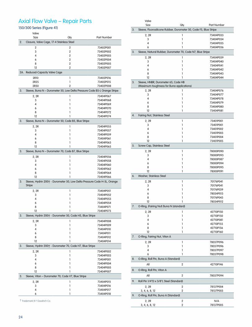
24
150/300 Series (Figure 41)
Valve Size Qty. Part Number
2. Closure, Valve Cage, 17-4 Stainless Steel
2346812
222222
73402P00173402P00273402P00373402P00473402P00573402P007
2A. Reduced-Capacity Valve Cage
2R102R252R50
112
73402P01673402P01573402P008
3. Sleeve, Buna N – Durometer 50, Low Delta Pressure Code B5-L Orange Stripe
2, 2R346812
111111
73404P06773404P06873404P06973404P07073404P07273404P074
3. Sleeve, Buna N – Durometer 50, Code B5, Blue Stripe
2, 2R346812
111111
73404P05573404P05773404P05973404P06173404P06373404P065
3. Sleeve, Buna N – Durometer 70, Code B7, Blue Stripe
2, 2R346812
111111
73404P05673404P05873404P06073404P06273404P06473404P066
3. Sleeve, Hydrin 200† - Durometer 50, Low Delta Pressure Code H-5L, Orange Stripe
2, 2R346812
111111
73404P05173404P05273404P05373404P05473404P07173404P073
3. Sleeve, Hydrin 200† - Durometer 50, Code H5, Blue Stripe
2, 2R346812
111111
73404P00873404P00973404P01073404P01173404P01273404P014
3. Sleeve, Hydrin 200† - Durometer 70, Code H7, Blue Stripe
2, 2R346812
111111
73404P00273404P00373404P00173404P00473404P00573404P007
3. Sleeve, Viton – Durometer 70, Code V7, Blue Stripe
2, 2R346
1111
73404P01573404P01673404P01773404P018
† Trademark B F Goodrich Co.
Axial Flow Valve – Repair Parts Valve Size Qty. Part Number
3. Sleeve, Fluorosilicone Rubber, Durometer 50, Code F5, Blue Stripe
2, 2R346
1111
73404P03373404P03473404P03573404P036
3. Sleeve, Natural Rubber, Durometer 70, Code N7, Blue Stripe
2, 2R346812
111111
73404P03973404P04073404P04173404P04273404P04373404P044
3. Sleeve, HNBR, Durometer 65, Code HB (Maximum toughness for Buna applications)
2, 2R346812
111111
73404P07673404P07773404P07873404P07973404P08073404P081
4. Fairing Nut, Stainless Steel
2, 2R346812
111111
73401P00173401P00173401P00273401P00373401P00473401P005
5. Screw Cap, Stainless Steel
2, 2R346812
111111
78000P09078000P09378000P08778000P09478000P09578000P091
6. Washer, Stainless Steel
2, 2R346812
111111
70176P04170176P04170176P03978034P01370176P04378034P012
7. O-Ring, (Fairing Nut) Buna N (standard)
2, 2R346812
111111
42710P15042710P15042710P08142710P15542710P15642710P160
7. O-Ring, Fairing Nut, Viton A
2, 2R346
1111
78037P09678037P09678037P09778037P098
8. O-Ring, Roll Pin, Buna A (Standard)
All 2 42710P146
8. O-Ring, Roll Pin, Viton A
All 2 78037P094
9. Roll Pin 1/4"D x 3/8"L Steel (Standard)
2, 2R3, 4, 6, 8, 12
22
78137P00478137P003
9. O-Ring, Roll Pin, Buna A (Standard)
2, 2R3, 4, 6, 8, 12
22
N/A78137P005
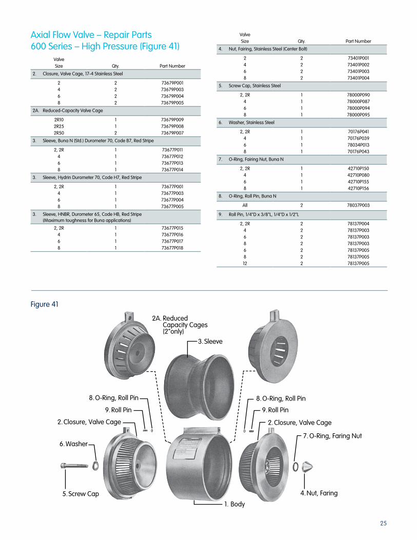
25
Valve Size Qty. Part Number
2. Closure, Valve Cage, 17-4 Stainless Steel
2468
2222
73679P00173679P00373679P00473679P005
2A. Reduced-Capacity Valve Cage
2R102R252R50
112
73679P00973679P00873679P007
3. Sleeve, Buna N (Std.) Durometer 70, Code B7, Red Stripe
2, 2R468
1111
73677P01173677P01273677P01373677P014
3. Sleeve, Hydrin Durometer 70, Code H7, Red Stripe
2, 2R468
1111
73677P00173677P00373677P00473677P005
3. Sleeve, HNBR, Durometer 65, Code HB, Red Stripe (Maximum toughness for Buna applications)
2, 2R468
1111
73677P01573677P01673677P01773677P018
Axial Flow Valve – Repair Parts600 Series – High Pressure (Figure 41)
Valve Size Qty. Part Number
4. Nut, Fairing, Stainless Steel (Center Bolt)
2468
2222
73401P00173401P00273401P00373401P004
5. Screw Cap, Stainless Steel
2, 2R468
1111
78000P09078000P08778000P09478000P095
6. Washer, Stainless Steel
2, 2R468
1111
70176P04170176P03978034P01370176P043
7. O-Ring, Fairing Nut, Buna N
2, 2R468
1111
42710P15042710P08042710P15542710P156
8. O-Ring, Roll Pin, Buna N
All 2 78037P003
9. Roll Pin, 1/4"D x 3/8"L, 1/4"D x 1/2"L
2, 2R4686812
2222222
78137P00478137P00378137P00378137P00378137P00578137P00578137P005
1. Body
2. Closure, Valve Cage
3. Sleeve
2A. Reduced Capacity Cages (2"only)
8. O-Ring, Roll Pin
9. Roll Pin
6. Washer
5. Screw Cap
8. O-Ring, Roll Pin
9. Roll Pin
2. Closure, Valve Cage
7. O-Ring, Faring Nut
4. Nut, Faring
Figure 41

26
Control Loop Assemblies
Description Quantity Part No.
1. Block, Manifold – Assembly (includes items #2 thru 13)
1 73957W001
2. Plug, Hex Hd. W/O-Ring 1 78479P001
3. Spring 1 71403P012
4. Washer 1 78034P016
5. Gasket 1 70019P106
6. Filter Assembly 1 78480P001
7. Screw, Hex Head, Steel Stainless Steel
22
78000P10612369P041
8. Plug, Hex Hd. W/O-Ring Stainless Steel
22
70176P04070176P045
9. Ring, Retaining 1 78074P029
10. Core, Restrictor 1 73659P003
11. O-Ring 5 78037P003
12. Roll Pin 3 78137P003
13. Plug, Pipe 1/4" W/17A pilot, Steel Stainless Steel W/18B pilot, Steel Stainless Steel
3322
78039P00311970P02578039P00311970P025
14. Nipple, Pipe – 1/4" 2 78044P006
15. Elbow 1 78041P002
16. Bushing, Reducing (use with 17A only)
1 78041P002
17A. Model 1203 – 180 – Pilot 1 73958G017
17B. Type 60 Series 1 See SB9800
18. Connector, Tube 1 78109P001
Control Loop Assemblies
Description Quantity Part No.
19. Sleeve 2 78109P004
20. Nut, Tube Connector 2 78109P003
21. Tubing – 3/8" 1 72201P013
22. Elbow 1 78109P002
23. Valve, Axial Flow 1 70019P106
24. Restrictor, Dampening 1 73688G002
25. Filter Assembly, Inspirator Block (optional)
22
74074K001
26. Inspirator Assembly 1 74067K001
27. Screw, Hex Head, Steel 2 78000P107
28. Washer, Flat, Steel 2 70176P040
29. Cap, 60 Series 1 55472P005
30. O-Ring Set, (for Restrictor Core only)
1 74069P003
31. Inspirator and O-Rings 1 74069G002
32. Filter Plug with O-Rings Inspirator only. For complete Inspirator, see item 26
1 78479P001
33. O-Ring (for Filter Plug) 1 78037P011
34. Filter 1 74074P001
2
3
456
78
1011
1
1211
14
18
139
29
17B
22
16
15
23
24
17A
1920
25
33
32
34
30/31
2728
26
Figure 42

27

Elster American Meter2221 Industrial Road Nebraska City, NE 68410-6889USA
T +1 402 873 8200F +1 402 873 7616
www.elster-americanmeter.com
T +1 519 650 1900 (Canada)F +1 519 650 1917 (Canada)
© 2013 by Elster. All rights reserved.
EAM-IIPL-9710.7 03/13
Information contained herein is subject to change without notice. Product specifications may change. Contact your Elster representative for the most current product information. Printed in the USA.
About Elster Group
Elster Group is the world’s leading manufacturer and supplier of highly accurate, high quality, integrated metering and utilization solutions to the gas, electricity and water industries. In addition, through its subsidiary Ipsen International, it is the leading global manufacturer of high level thermo-chemical treatment equipment.
The group has over 8,500 staff, operations in 38 countries and serves over 115 markets around the world. Elster’s high quality products and systems reflect the wealth of knowledge and experience gained from over 170 years of dedication to measuring precious resources and energy.