axial piston fixed pump a4fo - · pdf filefeatures fixed pump in axial piston swashplate...
TRANSCRIPT

Features ▶ Fixed pump in axial piston swashplate design for hydro-
static drives in an open circuit ▶ For use in mobile and stationary applications ▶ Flow is proportional to the drive speed and displacement. ▶ High power density ▶ High total efficiency ▶ Optimized dimensions for special installation situations ▶ Excellent suction characteristics ▶ Low noise level ▶ Long service life ▶ Economical design ▶ Through drive for combining additional pumps
RE 91455/03.2015, Bosch Rexroth AG
▶ Sizes 22 and 28 – Nominal pressure 400 bar – Maximum pressure 450 bar
▶ Sizes 71 to 500 – Nominal pressure 350 bar – Maximum pressure 400 bar
Axial piston fixed pumpA4FO
RE 91455Edition: 03.2015Replaces: 04.2000
Type code 2Hydraulic fluids 4Shaft seal 6Flow direction 6Working pressure range 7Technical data 8Dimensions sizes 22, 28 12Dimensions size 71 14Dimensions size 125 16Dimensions size 180 18Dimensions size 250 20Dimensions size 500 22Through drives dimensions 24Overview of attachment options 25Installation instructions 26Project planning notes 28Safety instructions 28
Contents

Bosch Rexroth AG, RE 91455/03.2015
2 A4FO | Axial piston fixed pumpType code
Type code
01 02 03 04 05 06 07 08 09 10 11
A4F O / –
Hydraulic fluid 022 028 071 125 180 250 50001 Mineral oil, HFD hydraulic fluid (no code) ● ● ● ● ● ● ●
HFA, HFB, HFC hydraulic fluid – – ● ● ● ● ● E–
High-speed version – – – – – ● ● H–
Axial piston unit02 Swashplate design, fixed displacement A4F
Operating mode03 Pump, open circuit O
Size (NG)04 Geometric displacement, see „Technical data“ on page 8 022 028 071 125 180 250 500
Series 022, 028 071 125 to 50005 Series 1, index 0 – ● – 10
Series 3, index 0 – – ● 30
Series 3, index 2 ● – – 32
Direction of rotation06 Viewed on drive shaft clockwise R
counter-clockwise L
Sealing material 022, 028 071 to 50007 NBR (nitrile rubber), shaft seal in FKM (fluoroelastomer) ● ‒ N
– ● P
FKM (fluoroelastomer) – ● V
Drive shaft (permissible input torque, see page 10) 022 028 071 125 180 250 50008 Splined shaft ANSI B92.1a ● ● – – – – – S
Splined shaft DIN 5480 – – ● ● ● ● ● Z
Parallel keyed shaft DIN 6885 – – ● ● ● ● ● P
Mounting flange 022 028 071 125 180 250 50009 SAE J744, 2-hole ● ● – – – – – C
ISO 3019, 4-hole – – ● ● ● ● – B
ISO 3019, 8-hole – – – – – – ● H
Working port1) 022, 028 071 to 50010 SAE pressure and suction port, at side, opposite ● – 12
SAE pressure and suction port, at side, offset by 90° 2nd pressure port B1 opposite B (plugged with flange plate on delivery)
–● 25
● = Available – = Not available
1) Fastening thread, metric

RE 91455/03.2015, Bosch Rexroth AG
Axial piston fixed pump | A4FO Type code
3
01 02 03 04 05 06 07 08 09 10 11
A4F O / –
Through drive (for attachment options, see page 25) 022 028 071 125 180 250 50011 Without through drive ● ● ● ● ● ● ● N00
With through drive for mounting an axial piston unit or gear pump ● ● ● – – – ● K…
Universal through drive (can be modified) – – – ● ● ● – U…
Flange SAE J744 Hub for splined shaft SAE J744
82-2 (A) 5/8 in (16-4) ● ● ● ● ● ● ● …01
101-2 (B) 7/8 in (22-4) ● ● – – – – – …02
101-2 (B) 7/8 in (22-4) – – ● ● ● ● ○ …68
Flange ISO 3019-2 (metric) Hub for splined shaft SAE J744
80, 2-hole 3/4 in (19-4) – – ● ● ● ● ○ …B2
100, 2-hole 7/8 in (22-4) – – ● ● ● ● ○ …B3
100, 2-hole 1 in (25-4) – – ● ● ● ● ○ …B4
125, 2-hole 1 1/4 in (32-4) – – ● ● ● ● ○ …B5
125, 2-hole 1 1/2 in (38-4) – – – ● ● ● ○ …B6
180, 4-hole 1 3/4 in (44-4) – – – – ● ● ● …B7
Flange ISO 3019-2 (metric) Hub for splined shaft DIN 5480
125, 4-hole W32×2×14×9g – – ● ● ● ● ○ …31
140, 4-hole W40×2×18×9g – – ● ● ● ● ○ …33
160, 4-hole W50×2×24×9g – – – ● ● ● ● …34
224, 4-hole W60×2×28×9g – – – – – ● ● …35
315, 8-hole W80×3×25×9g – – – – – – ● …43
With through-drive shaft, without hub, without intermediate flange, closed with cover
– – ● ● ● ● ● …99
● = Available ○ = On request – = Not available
Notes ▶ Note the project planning notes on page 28. ▶ Preservation:
– Up to 12 months as standard – Up to 24 months long-term (state in plain text when
ordering)
Bosch Rexroth AG, RE 91455/03.2015
4 A4FO | Axial piston fixed pumpHydraulic fluids
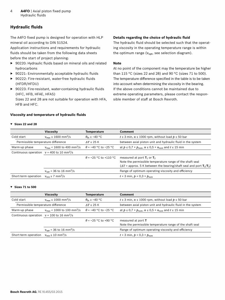
Hydraulic fluids
The A4FO fixed pump is designed for operation with HLP mineral oil according to DIN 51524. Application instructions and requirements for hydraulic fluids should be taken from the following data sheets before the start of project planning:
▶ 90220: Hydraulic fluids based on mineral oils and related hydrocarbons
▶ 90221: Environmentally acceptable hydraulic fluids ▶ 90222: Fire-resistant, water-free hydraulic fluids
(HFDR/HFDU) ▶ 90223: Fire-resistant, water-containing hydraulic fluids
(HFC, HFB, HFAE, HFAS) Sizes 22 and 28 are not suitable for operation with HFA, HFB and HFC.
Details regarding the choice of hydraulic fluidThe hydraulic fluid should be selected such that the operat-ing viscosity in the operating temperature range is within the optimum range (νopt, see selection diagram).
NoteAt no point of the component may the temperature be higher than 115 °C (sizes 22 and 28) and 90 °C (sizes 71 to 500).The temperature difference specified in the table is to be taken into account when determining the viscosity in the bearing. If the above conditions cannot be maintained due to extreme operating parameters, please contact the respon-sible member of staff at Bosch Rexroth.
Viscosity and temperature of hydraulic fluids
▼ Sizes 22 and 28
Viscosity Temperature Comment
Cold start νmax ≤ 1600 mm2/s θSt ≥ −40 °C t ≤ 3 min, n ≤ 1000 rpm, without load p ≤ 50 bar
Permissible temperature difference ΔT ≤ 25 K between axial piston unit and hydraulic fluid in the system
Warm-up phase νmax < 1600 to 400 mm2/s θ = −40 °C to −25 °C at p ≤ 0,7 × pnom, n ≤ 0,5 × nnom and t ≤ 15 min
Continuous operation ν = 400 to 10 mm2/s
θ = −25 °C to +110 °C measured at port T1 or T2
Note the permissible temperature range of the shaft seal(ΔT = approx. 5 K between the bearing/shaft seal and port T1/T2)
νopt = 36 to 16 mm2/s Range of optimum operating viscosity and efficiency
Short-term operation νmin ≥ 7 mm2/s t < 3 min, p < 0,3 × pnom
▼ Sizes 71 to 500
Viscosity Temperature Comment
Cold start νmax ≤ 1000 mm2/s θSt ≥ −40 °C t ≤ 3 min, n ≤ 1000 rpm, without load p ≤ 50 bar
Permissible temperature difference ΔT ≤ 25 K between axial piston unit and hydraulic fluid in the system
Warm-up phase νmax < 1000 to 100 mm2/s θ = −40 °C to −25 °C at p ≤ 0,7 × pnom, n ≤ 0,5 × nnom and t ≤ 15 min
Continuous operation ν = 100 to 16 mm2/s
θ = −25 °C to +90 °C measured at port TNote the permissible temperature range of the shaft seal
νopt = 36 to 16 mm2/s Range of optimum operating viscosity and efficiency
Short-term operation νmin ≥ 10 mm2/s t < 3 min, p < 0,3 × pnom

RE 91455/03.2015, Bosch Rexroth AG
Axial piston fixed pump | A4FO Hydraulic fluids
5
▼ Selection diagram
-40 -25 -10 10 30 50 90 1157007
10
4060
20
100
200
400600
10001600
VG 22VG 32VG 46VG 68VG 100
16
36
Optimum operating viscosity range vopt
Optimum efficiency
Temperature θ [°C]
Visc
osity
v [
mm
2 /s]
Filtration of the hydraulic fluidFiner filtration improves the cleanliness level of the hydraulic fluid, which in turn increases the service life of the axial piston unit.A cleanliness level of at least 20/18/15 is to be maintained according to ISO 4406.At very high hydraulic fluid temperatures (90 °C to maxi-mum 110 °C, measured at port T, not permitted for sizes 71 to 500), a cleanliness level of at least 19/17/14 in accor-dance with ISO 4406 is necessary.
Bosch Rexroth AG, RE 91455/03.2015
6 A4FO | Axial piston fixed pumpShaft seal
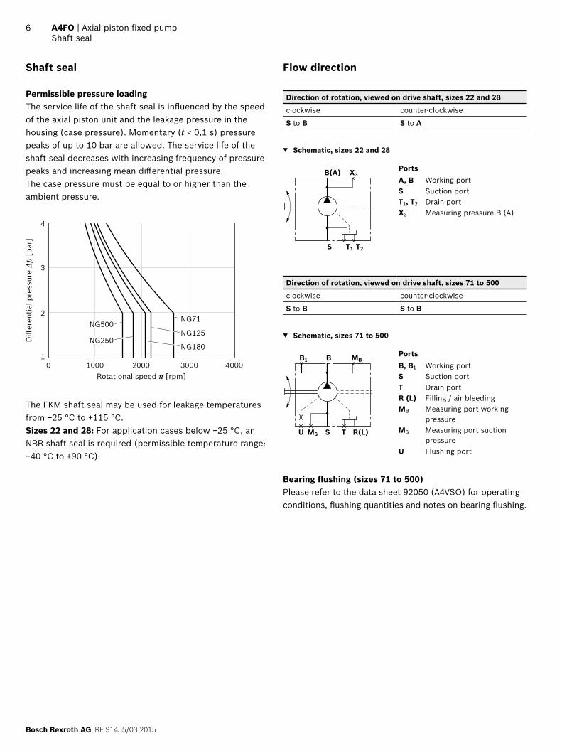
Shaft seal
Permissible pressure loadingThe service life of the shaft seal is influenced by the speed of the axial piston unit and the leakage pressure in the housing (case pressure). Momentary (t < 0,1 s) pressure peaks of up to 10 bar are allowed. The service life of the shaft seal decreases with increasing frequency of pressure peaks and increasing mean differential pressure.The case pressure must be equal to or higher than the ambient pressure.
1
2
3
4
1000 2000 3000 40000
Diff
eren
tial p
ress
ure
Δp [
bar]
Rotational speed n [rpm]
NG71NG500
NG250NG180
NG125
The FKM shaft seal may be used for leakage temperatures from −25 °C to +115 °C. Sizes 22 and 28: For application cases below −25 °C, an NBR shaft seal is required (permissible temperature range: −40 °C to +90 °C).
Flow direction
Direction of rotation, viewed on drive shaft, sizes 22 and 28
clockwise counter-clockwise
S to B S to A
▼ Schematic, sizes 22 and 28
T1S
B(A)
T2
X3PortsA, B Working portS Suction portT1, T2 Drain port X3 Measuring pressure B (A)
Direction of rotation, viewed on drive shaft, sizes 71 to 500
clockwise counter-clockwise
S to B S to B
▼ Schematic, sizes 71 to 500
TS
B
R(L)
MBB1
MSU
PortsB, B1 Working portS Suction portT Drain portR (L) Filling / air bleedingMB Measuring port working
pressureMS Measuring port suction
pressureU Flushing port
Bearing flushing (sizes 71 to 500)Please refer to the data sheet 92050 (A4VSO) for operating conditions, flushing quantities and notes on bearing flushing.

RE 91455/03.2015, Bosch Rexroth AG
Axial piston fixed pump | A4FO Working pressure range
7
Working pressure range
Pressure at working ports A or B and B1
Sizes 22 and 28 Sizes 71 to 500 Definition
Nominal pressure pnom 400 bar absolute 350 bar absolute The nominal pressure corresponds to the maximum design pressure.
Maximum pressure pmax 450 bar absolute 400 bar absolute The maximum pressure corresponds the maximum working pres-sure within the single operating period. The sum of the single operating periods must not exceed the total operating period.
Single operating period 1 s 1 s
Total operating period 300 h 300 h
Minimum pressure (high-pressure side)
25 bar absolute – Minimum pressure on high-pressure side (A or B and B1) required to prevent damage to the axial piston unit.
Rate of pressure change RA max 16000 bar/s 16000 bar/s Maximum permissible rate of pressure build-up and reduction during a pressure change over the entire pressure range.
Pressure at suction port S (inlet)
Minimum pressure pS min 0,8 bar absolute 0,8 bar absolute Minimum pressure at suction port S (inlet) that is required in order to avoid damage to the axial piston unit. The minimum pressure depends on the speed of the axial piston unit.
Maximum pressure pS max 2 bar absolute 30 bar absolute
▼ Rate of pressure change RA max
pnom
∆t
∆p
Time t
Pres
sure
p
▼ Pressure definitionPr
essu
re p
t1
t2tnSingle operating period
Minimum pressure (high-pressure side)
Maximum pressure pmax
Nominal pressure pnom
Time t
Total operating period = t1 + t2 + ... + tn
NoteWorking pressure range valid when using hydraulic fluids based on mineral oils. Values for other hydraulic fluids, please contact us.

Bosch Rexroth AG, RE 91455/03.2015
8 A4FO | Axial piston fixed pumpTechnical data
Technical data
Size NG 22 28 71 125 180 250/H1) 500/H1)
Displacement, geometric, per revolution Vg cm3 22 28 71 125 180 250 500
Maximum rotational speed2) nnom rpm 3600 3000 2200 1800 1800 1500 / 1900
1320 /1500
Maximum rotational speed3) nmax rpm 4500 3750 2700 2200 2100 1800 / 2100
1600 / 1800
Flow at Vg and nnom qV l/min 79 84 156 225 324 375 / 475
660 / 750
Power at Vg, nnom and Δp = 400 bar
P kW 53 56 914) 1314) 1894) 219 / 2774)
385 / 4384)
Torque at Vg and Δp = 400 bar T Nm 140 178 3964) 6964) 10034) 13934) 27854)
Rotary stiffness drive shaft
Shaft end S c kNm/rad 29,9 29,9 – – – – –
Shaft end P c kNm/rad – – 146 260 328 527 1145
Shaft end Z c kNm/rad – – 146 263 332 543 1136
Moment of inertia for rotary group JGR kgm2 0,0017 0,0017 0,0121 0,0300 0,055 0,0959 0,3325
Maximum angular acceleration a rad/s2 38000 38000 20000 13000 10000 8000 4800
Case volume V l 0,3 0,3 2,0 3,0 4,0 7,0 11,0
Weight (approx.) m kg 13,5 13,5 34 61 76 120 220
▼ Maximum permissible speed (speed limit)
Spee
d n
/ n m
ax [
rpm
]
Inlet pressure pabs [bar]0.8
1.0
1.1
1.2
1.25
0.91.0 1.2 1.4 1.6 1.8 2.0
Notes ▶ Theoretical values, without efficiency and tolerances;
values rounded ▶ Operation above the maximum values or below the
minimum values may result in a loss of function, a reduced service life or the destruction of the axial piston unit. Bosch Rexroth recommend testing the loads by means of experiment or calculation / simulation and comparison with the permissible values.
Determining operating characteristics
Flow qv =Vg × n × ηv
[l/min]1000
Torque T = Vg × Δp
[Nm]20 × π × ηmh
Power P =2 π × T × n
=qv × Δp
[kW]60000 600 × ηt
Key
Vg = Displacement per revolution [cm3]
Δp = Differential pressure [bar]
n = Rotational speed [rpm]
ηv = Volumetric efficiency
ηmh = Mechanical-hydraulic efficiency
ηt = Total efficiency (ηt = ηv × ηmh)
1) H = High-speed version2) The values are valid:
‒ At absolute pressure pabs = 1 bar at suction port S ‒ For the optimal viscosity range of νopt = 36 to 16 mm2/s ‒ For hydraulic fluid based on mineral oils.
3) Maximum speed (speed limit) with increased inlet pressure pabs at suction port S, see diagram.
4) At ∆p = 350 bar
RE 91455/03.2015, Bosch Rexroth AG
Axial piston fixed pump | A4FO Technical data
9
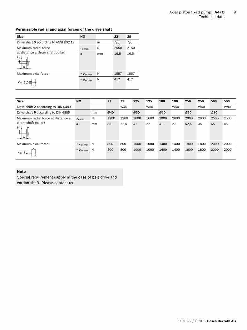
Permissible radial and axial forces of the drive shaft
Size NG 22 28
Drive shaft S according to ANSI B92.1a in 7/8 7/8
Maximum radial force at distance a (from shaft collar)
a
Fq
Fq max N 2550 2150
a mm 16,5 16,5
Maximum axial force
–+Fax
+ Fax max N 1557 1557
− Fax max N 417 417
Size NG 71 71 125 125 180 180 250 250 500 500
Drive shaft Z according to DIN 5480 W40 W50 W50 W60 W80
Drive shaft P according to DIN 6885 mm Ø40 Ø50 Ø50 Ø60 Ø80
Maximum radial force at distance a (from shaft collar)
a
Fq
Fq max N 1200 1200 1600 1600 2000 2000 2000 2000 2500 2500
a mm 35 22,5 41 27 41 27 52,5 35 65 45
Maximum axial force
–+Fax
+ Fax max N 800 800 1000 1000 1400 1400 1800 1800 2000 2000
− Fax max N 800 800 1000 1000 1400 1400 1800 1800 2000 2000
NoteSpecial requirements apply in the case of belt drive and cardan shaft. Please contact us.

Bosch Rexroth AG, RE 91455/03.2015
10 A4FO | Axial piston fixed pumpTechnical data
Permissible input and through-drive torques
Size NG 22 28
Torque at Vg and Δp = 400 bar1) T Nm 140 178
Input torque at drive shaft, maximum2)
ANSI B92.1a S TE max Nm 192 192
7/8 in 7/8 in
Maximum through-drive torque TD max Nm 192 192
Size NG 71 125 180 250 500
Torque at Vg and Δp = 350 bar1) T Nm 396 696 1003 1393 2785
Input torque at drive shaft, maximum2)
DIN 5480 Z TE max Nm 790 1392 2004 2782 5566
W40 W50 W50 W60 W80
DIN 6885 P TE max Nm 700 1392 1400 2300 5200
Ø40 Ø50 Ø50 Ø60 Ø80
Maximum through-drive torque TD max Nm 395 696 1002 1391 2783
▼ Torque distribution
T1
TD
TE
T2
T31st pump 2nd pump
Torque at 1st pump T1
Torque at 2nd pump T2
Torque at 3rd pump T3
Input torque TE = T1 + T2 + T3
TE < TE max
Through-drive torque TD = T2 + T3
TD < TD max
1) Efficiency not considered2) For drive shafts free of radial force

RE 91455/03.2015, Bosch Rexroth AG
Axial piston fixed pump | A4FO Technical data
11
Flow and power
▼ Size 71
0 100 200 300 350
5050
0 0
100
150
100
150
qV
PqV max
PqV null
Flow
qV
[l/m
in]
Dri
ve p
ower
P [
kW]
Working pressure p [bar]
n = 2200 rpmn = 1500 rpm
▼ Size 125
0 100 200 300 350
PqV max
PqV null
50100
0 0
200
300
100
150
qV
Flow
qV
[l/m
in]
Dri
ve p
ower
P [
kW]
Working pressure p [bar]
n = 1800 rpmn = 1500 rpm
▼ Size 180
0 100 200 300 350
PqV max
PqV null
50100
0
200
300
100
150
400 200qV
0
Flow
qV
[l/m
in]
Dri
ve p
ower
P [
kW]
Working pressure p [bar]
n = 1800 rpmn = 1500 rpm
▼ Size 250
0 100 200 300 350
PqV max
PqV null
50100
0
200
300
100
150
400
500
200
250
qV
0Fl
ow q
V [l
/min
]
Dri
ve p
ower
P [
kW]
Working pressure p [bar]
n = 1500 rpmn = 1000 rpm
▼ Size 500
0 100 200 300 350
PqV max
PqV null 50100
0
300
100
150
400
500
200
250
600
700
800
300
350
400
200
qV
0
Flow
qV
[l/m
in]
Dri
ve p
ower
P [
kW]
Working pressure p [bar]
n = 1320 rpmn = 1000 rpm
Bosch Rexroth AG, RE 91455/03.2015
12 A4FO | Axial piston fixed pumpDimensions sizes 22, 28
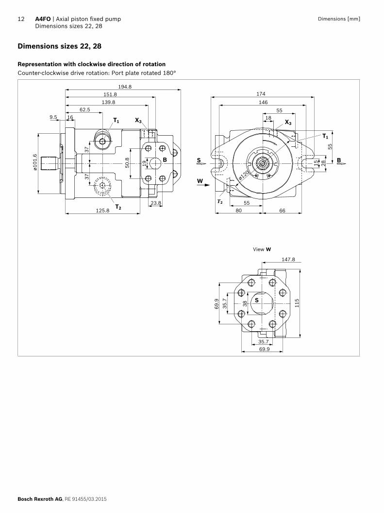
Dimensions [mm]
Dimensions sizes 22, 28
Representation with clockwise direction of rotationCounter-clockwise drive rotation: Port plate rotated 180°
125.8
ø101
.6
23.8
194.8151.8
139.862.5
9.5 16
37
50.8
19
37
T2
T1 X3
80 6655
1855
146
174
55
15 28
ø120
T2
T1
X3
W
S B
147.8
35.769.9
115
69.9
35.7
38
S
B
View W
RE 91455/03.2015, Bosch Rexroth AG
Axial piston fixed pump | A4FO Dimensions sizes 22, 28
13Dimensions [mm]
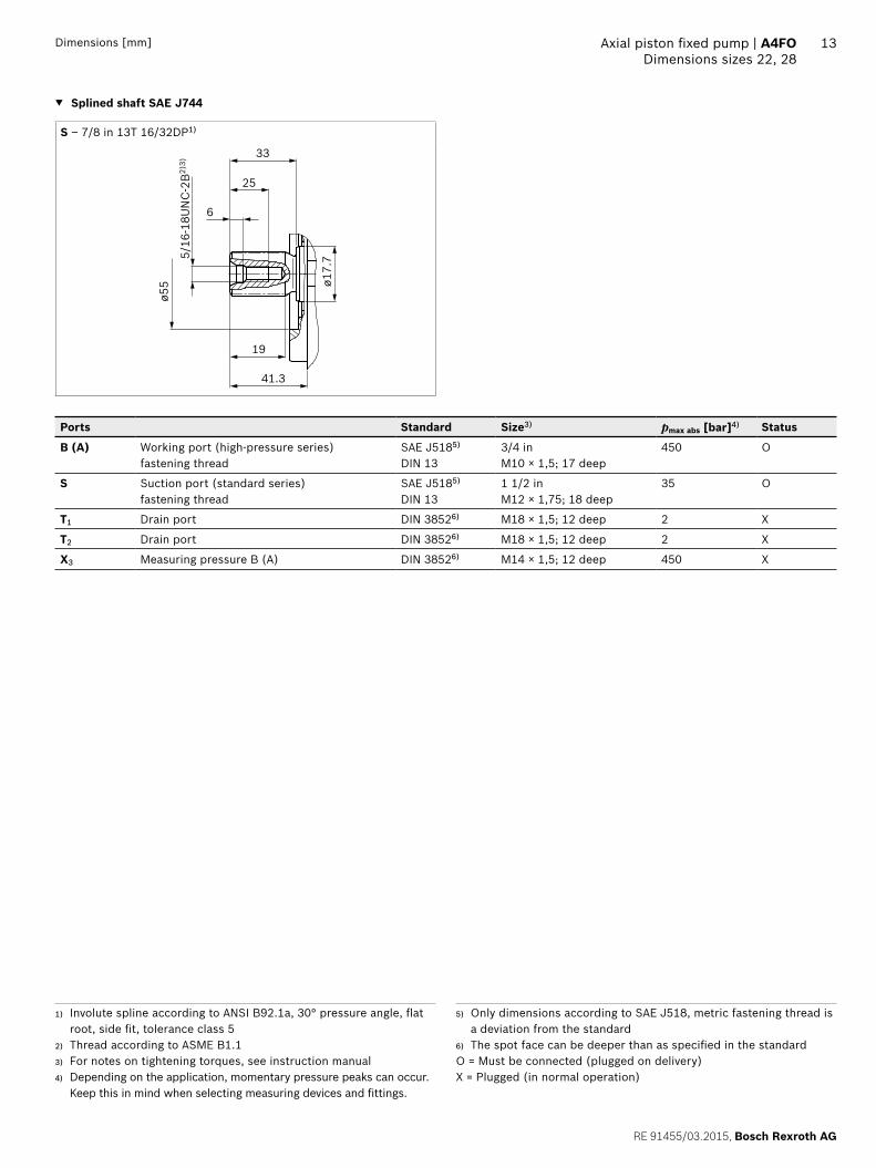
▼ Splined shaft SAE J744
S – 7/8 in 13T 16/32DP1)
41.3
ø55
25
19
5/16
-18U
NC
-2B
2)3)
ø17.
7
33
6
Ports Standard Size3) pmax abs [bar]4) Status
B (A) Working port (high-pressure series) fastening thread
SAE J5185) DIN 13
3/4 in M10 × 1,5; 17 deep
450 O
S Suction port (standard series) fastening thread
SAE J5185) DIN 13
1 1/2 in M12 × 1,75; 18 deep
35 O
T1 Drain port DIN 38526) M18 × 1,5; 12 deep 2 X
T2 Drain port DIN 38526) M18 × 1,5; 12 deep 2 X
X3 Measuring pressure B (A) DIN 38526) M14 × 1,5; 12 deep 450 X
1) Involute spline according to ANSI B92.1a, 30° pressure angle, flat root, side fit, tolerance class 5
2) Thread according to ASME B1.13) For notes on tightening torques, see instruction manual4) Depending on the application, momentary pressure peaks can occur.
Keep this in mind when selecting measuring devices and fittings.
5) Only dimensions according to SAE J518, metric fastening thread is a deviation from the standard
6) The spot face can be deeper than as specified in the standardO = Must be connected (plugged on delivery)X = Plugged (in normal operation)

Bosch Rexroth AG, RE 91455/03.2015
14 A4FO | Axial piston fixed pumpDimensions size 71
Dimensions [mm]
Dimensions size 71
Representation with clockwise and counter-clockwise direction of rotation
T
15
106182170
83.5 85
170
45° 45°ø180
R (L)
ø140
h8
8
3410 27.8
13220
232273
25 57.2
83.5
87
MSMB
B1
T
BB
X
61
5077.8
42.9
S
View X

RE 91455/03.2015, Bosch Rexroth AG
Axial piston fixed pump | A4FO Dimensions size 71
15Dimensions [mm]
▼ Splined shaft DIN 5480 ▼ Parallel keyed shaft DIN 6885
Z – W40×2×18×9g P – AS12×8×68
45
37
M12
× 1
.751)
2)
⌀50
9.528
43
70
M12
× 1
.751)
2)
⌀50
⌀40
+0.0
18+0
.002
9.5
28Key width 12
Ports Standard Size2) pmax abs [bar]3) Status
B Working port (high-pressure series) fastening thread
SAE J5184) DIN 13
1 in M12 × 1,75; 17 deep
400 O
B1 2nd working port (high-pressure series) fastening thread
SAE J5184) DIN 13
1 in M12 × 1,75; 17 deep
400 X
S Suction port (standard series) fastening thread
SAE J5184) DIN 13
2 inM12 × 1,75; 20 deep
30 O
T Drain port DIN 38525) M27 × 2; 16 deep 4 X
R (L) Filling / air bleeding (drain port)
DIN 38525) M27 × 2; 16 deep 4 O
MB Measuring pressure B DIN 38525) M14 × 1,5; 12 deep 400 X
MS Measuring pressure S DIN 38525) M14 × 1,5; 12 deep 30 X
1) Center bore according to DIN 332 (thread according to DIN 13)2) For notes on tightening torques, see instruction manual3) Depending on the application, momentary pressure peaks can occur.
Keep this in mind when selecting measuring devices and fittings.
4) Only dimensions according to SAE J518, metric fastening thread is a deviation from the standard.
5) The spot face can be deeper than as specified in the appropriate standard.
O = Must be connected (plugged on delivery)X = Plugged (in normal operation)
Bosch Rexroth AG, RE 91455/03.2015
16 A4FO | Axial piston fixed pumpDimensions size 125
Dimensions [mm]
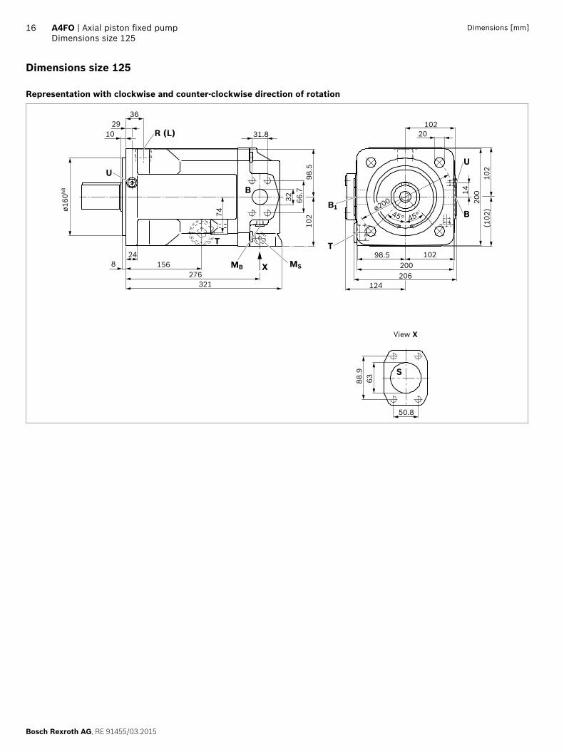
Dimensions size 125
Representation with clockwise and counter-clockwise direction of rotation
X
ø160
h8
8 MS
321
24MB
276156
2910
36
31.8
32 66.7
102
98.5
74
B
T
U
45° 45°ø200
T
B
U
B1
10220
20014
102
(102
)
124206200
10298.5
50.8
S88
.963
R (L)
View X

RE 91455/03.2015, Bosch Rexroth AG
Axial piston fixed pump | A4FO Dimensions size 125
17Dimensions [mm]
▼ Splined shaft DIN 5480 ▼ Parallel keyed shaft DIN 6885
Z – W50×2×24×9g P – AS14×9×80
54
45
M16
× 2
1)2)
⌀60
1236
53.5
82
M16
× 2
1)2)
⌀60
⌀50
+0.0
18+0
.002
12
36Key width 14
Ports Standard Size2) pmax abs [bar]3) Status
B Working port (high-pressure series) fastening thread
SAE J5184) DIN 13
1 1/4 in M14 × 2; 19 deep
400 O
B1 2nd working port (high-pressure series) fastening thread
SAE J5184) DIN 13
1 1/4 in M14 × 2; 19 deep
400 X
S Suction port (standard series) fastening thread
SAE J5184) DIN 13
2 1/2 in M12 × 1,75; 17 deep
30 O
T Drain port DIN 38525) M33 × 2; 18 deep 4 X
R (L) Filling / air bleeding (drain port)
DIN 38525) M33 × 2; 18 deep 4 O
MB Measuring pressure B DIN 38525) M14 × 1,5; 12 deep 400 X
MS Measuring pressure S DIN 38525) M14 × 1,5; 12 deep 30 X
U Bearing flushing DIN 38525) M14 × 1,5; 12 deep 10 X
1) Center bore according to DIN 332 (thread according to DIN 13)2) For notes on tightening torques, see instruction manual3) Depending on the application, momentary pressure peaks can
occur. Keep this in mind when selecting measuring devices and fittings.
4) Only dimensions according to SAE J518, metric fastening thread is a deviation from the standard.
5) The spot face can be deeper than as specified in the appropriate standard.
O = Must be connected (plugged on delivery)X = Plugged (in normal operation)

Bosch Rexroth AG, RE 91455/03.2015
18 A4FO | Axial piston fixed pumpDimensions size 180
Dimensions [mm]
Dimensions size 180
Representation with clockwise and counter-clockwise direction of rotation
ø160
h8
31.8
31
U
45° 45°
ø200
S75106.
4
61.9
114.5 114.5136.5
98.5200206
1420
0
102
(102
)B1 B
B
U
TT
R(L)
MS
MB
342285
24
1568
74
102
66.7
36
20102 102
98.5
X
29
10
View X

RE 91455/03.2015, Bosch Rexroth AG
Axial piston fixed pump | A4FO Dimensions size 180
19Dimensions [mm]
▼ Splined shaft DIN 5480 ▼ Parallel keyed shaft DIN 6885
Z – W50×2×24×9g P – AS14×9×80
54
45
M16
× 2
1)2)
⌀70
1236
48.5
82
M16
× 2
1)2)
⌀70
⌀50 12
36
+0.0
18+0
.002
Key width 14
Ports Standard Size2) pmax abs [bar]3) Status
B Working port (high-pressure series) fastening thread
SAE J5184) DIN 13
1 1/4 in M14 × 2; 19 deep
400 O
B1 2nd working port (high-pressure series) fastening thread
SAE J5184) DIN 13
1 1/4 in M14 × 2; 19 deep
400 X
S Suction port (standard series) fastening thread
SAE J5184) DIN 13
3 in M16 × 2; 24 deep
30 O
T Drain port DIN 38525) M33 × 2; 18 deep 4 X
R (L) Filling / air bleeding (drain port)
DIN 38525) M33 × 2; 18 deep 4 O
MB Measuring pressure B DIN 38525) M14 × 1,5; 12 deep 400 X
MS Measuring pressure S DIN 38525) M14 × 1,5; 12 deep 30 X
U Bearing flushing DIN 38525) M14 × 1,5; 12 deep 10 X
1) Center bore according to DIN 332 (thread according to DIN 13)2) For notes on tightening torques, see instruction manual3) Depending on the application, momentary pressure peaks can
occur. Keep this in mind when selecting measuring devices and fittings.
4) Only dimensions according to SAE J518, metric fastening thread is a deviation from the standard.
5) The spot face can be deeper than as specified in the appropriate standard.
O = Must be connected (plugged on delivery)X = Plugged (in normal operation)

Bosch Rexroth AG, RE 91455/03.2015
20 A4FO | Axial piston fixed pumpDimensions size 250
Dimensions [mm]
Dimensions size 250
Representation with clockwise and counter-clockwise direction of rotation
X
ø224
h8
30203
38
91
79.4
131
138
346401
1610
48
36.5129
24
124.5 130260268
176
265
34.5
45° 45°
106.
4
ø280
75
61.9
8 MSMB
T
U
R (L)
BB1
T
B
U
S
View X
RE 91455/03.2015, Bosch Rexroth AG
Axial piston fixed pump | A4FO Dimensions size 250
21Dimensions [mm]
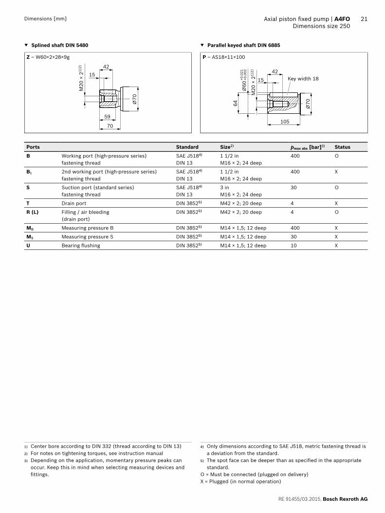
▼ Splined shaft DIN 5480 ▼ Parallel keyed shaft DIN 6885
Z – W60×2×28×9g P – AS18×11×100
70
59
M20
× 2
1)2)
⌀70
1542
64
105
M20
× 2
1)2)
⌀70
⌀60
+0.0
21+0
.002
15
42Key width 18
Ports Standard Size2) pmax abs [bar]3) Status
B Working port (high-pressure series) fastening thread
SAE J5184) DIN 13
1 1/2 in M16 × 2; 24 deep
400 O
B1 2nd working port (high-pressure series) fastening thread
SAE J5184) DIN 13
1 1/2 in M16 × 2; 24 deep
400 X
S Suction port (standard series) fastening thread
SAE J5184) DIN 13
3 in M16 × 2; 24 deep
30 O
T Drain port DIN 38525) M42 × 2; 20 deep 4 X
R (L) Filling / air bleeding (drain port)
DIN 38525) M42 × 2; 20 deep 4 O
MB Measuring pressure B DIN 38525) M14 × 1,5; 12 deep 400 X
MS Measuring pressure S DIN 38525) M14 × 1,5; 12 deep 30 X
U Bearing flushing DIN 38525) M14 × 1,5; 12 deep 10 X
1) Center bore according to DIN 332 (thread according to DIN 13)2) For notes on tightening torques, see instruction manual3) Depending on the application, momentary pressure peaks can
occur. Keep this in mind when selecting measuring devices and fittings.
4) Only dimensions according to SAE J518, metric fastening thread is a deviation from the standard.
5) The spot face can be deeper than as specified in the appropriate standard.
O = Must be connected (plugged on delivery)X = Plugged (in normal operation)
Bosch Rexroth AG, RE 91455/03.2015
22 A4FO | Axial piston fixed pumpDimensions size 500
Dimensions [mm]
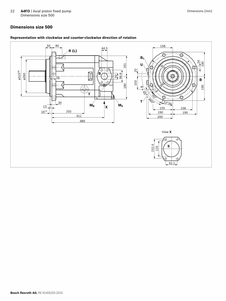
Dimensions size 500
Representation with clockwise and counter-clockwise direction of rotation
X
ø315
h8
ø260
16+5
1330
255411
489
8050
16
152.
412
5
190
19024
158
92.1
50
180
161
96.8
200190 190
158155
103
20
22°30´
45°
405
360
44.5
MSMB
T
R (L)
B1
U
B
T
S
B
8 x 45° = 360°
View X

RE 91455/03.2015, Bosch Rexroth AG
Axial piston fixed pump | A4FO Dimensions size 500
23Dimensions [mm]
▼ Splined shaft DIN 5480 ▼ Parallel keyed shaft DIN 6885
Z – W80×3×25×9g P – AS22×14×125
90
76
M20
× 2
1)2)
⌀10
0
1542
85
130
M20
× 2
1)2)
⌀10
0
⌀80
+0.0
30+0
.011
15
42Key width 22
Ports Standard Size2) pmax abs [bar]3) Status
B Working port (high-pressure series) fastening thread
SAE J5184) DIN 13
2 in M20 × 2,5; 24 deep
400 O
B1 2nd working port (high-pressure series) fastening thread
SAE J5184) DIN 13
2 in M20 × 2,5; 24 deep
400 X
S Suction port (standard series) fastening thread
SAE J5184) DIN 13
5 in M16 × 2; 23 deep
30 O
T Drain port DIN 38525) M48 × 2; 22 deep 4 X
R (L) Filling / air bleeding (drain port)
DIN 38525) M48 × 2; 22 deep 4 O
MB Measuring pressure B DIN 38525) M18 × 1,5; 12 deep 400 X
MS Measuring pressure S DIN 38525) M18 × 1,5; 12 deep 30 X
U Bearing flushing DIN 38525) M18 × 1,5; 12 deep 10 X
1) Center bore according to DIN 332 (thread according to DIN 13)2) For notes on tightening torques, see instruction manual3) Depending on the application, momentary pressure peaks can
occur. Keep this in mind when selecting measuring devices and fittings.
4) Only dimensions according to SAE J518, metric fastening thread is a deviation from the standard.
5) The spot face can be deeper than as specified in the appropriate standard.
O = Must be connected (plugged on delivery)X = Plugged (in normal operation)

Bosch Rexroth AG, RE 91455/03.2015
24 A4FO | Axial piston fixed pumpThrough drives dimensions
Dimensions [mm]
Through drives dimensions
Sizes 22 and 28
▼ K01: Flange 82-2 (A), hub for splined shaft 5/8 in (16-4)
106.6
X3
B
17ø8
2.55
10
ø17.
59
194.8
M10 × 1,5, 15 deep
▼ K02: Flange 101-2 (B), hub for splined shaft 7/8 in (22-4)
M10 × 1,5, 15 deep
146
ø101
.6
X3
B
1112
213.2
Sizes 71 to 500
▼ For through drives see data sheet 92050 (A4VSO)
A1
▼ Dimensions for A1
Code 71 125 180 250 500
K/U01 269 335 360 419 ○K/U68 300 335 360 419 ○K/UB2 269 335 360 419 ○K/UB3 269 335 360 419 ○K/UB4 294 335 360 419 ○K/UB5 299 335 360 419 ○K/UB6 – 335 360 419 ○K/UB7 – – 373 419 500
K/U31 294 335 360 419 ○K/U33 294 335 360 419 ○K/U34 – 335 360 419 475
K/U35 – – – 435 511
K/U43 – – – – 560
K/U99 286,5 334 359 419 497
○ = on request

RE 91455/03.2015, Bosch Rexroth AG
Axial piston fixed pump | A4FO Overview of attachment options
25
Overview of attachment options
Through drive A4FO1) Attachment of 2nd pump
Flange Hub for splined shaft
Code A4VSO/G NG (shaft)
A4CSG NG (shaft)
A10V(S)O/ 31(2) NG (shaft)
A10V(S)O/52(3) NG (shaft)
External gear pump2)
SAE J744
82-2 (A) 5/8 in K01 – – – – AZPF
101-2 (B) 7/8 in K02, K/U68
– – 28 (S)/31 28 (S) AZPN
ISO 3019-2 (metric)
80, 2-hole 3/4 in K/UB2 – – 18 (S)/31 10 (S) –
100, 2-hole 7/8 in K/UB3 – – 28 (S)/31 – –
1 in K/UB4 – – 45 (S)/31 – –
125, 2-hole 1 1/4 in K/UB5 – – 71 (S)/31 – –
1 1/2 in K/UB6 – – 100 (S)/31 – –
125, 4-hole W32×2×14×9g K/U31 40 (Z) – – – –
140, 4-hole W40×2×18×9g K/U33 71 (Z) – – – –
160, 4-hole W50×2×24×9g K/U34 125 (Z) – – – –
180, 4-hole 1 3/4 in K/UB7 – – 140 (S)/31/32 – –
224, 4-hole W60×2×28×9g K/U35 250 (Z) 250 (Z) – – –
315, 8-hole W80×3×25×9g K/U43 500 (Z) 500 (Z) – – –
1) Additional through drives are available on request2) Bosch Rexroth recommends special versions of the external gear
pumps. Please contact us.

Bosch Rexroth AG, RE 91455/03.2015
26 A4FO | Axial piston fixed pumpInstallation instructions
Installation instructions
GeneralThe axial piston unit must be filled with hydraulic fluid and air bled during commissioning and operation. This must also be observed following a longer standstill as the axial piston unit may empty via the hydraulic lines.Particularly in the installation position „drive shaft upwards“, filling and air bleeding must be carried out completely as there is, for example, a danger of dry running.For sizes 22 and 28, the pump housing is internally con-nected to the suction chamber. A separate drain line from the housing to the reservoir is not needed. A drain line is required for sizes 71 to 500. If a shared drain line is used for several units, make sure that the relevant case pressure is not exceeded. The shared drain line must be dimensioned to ensure that the maxi-mum permissible case pressure of all connected units is not exceeded in any operational circumstances, particularly at cold start. If this is not possible, separate drain lines must be laid if necessary.To achieve favorable noise values, decouple all connecting lines using elastic elements and avoid above-reservoir installation. In all operating conditions, the suction lines and the drain lines must flow into the reservoir below the minimum fluid level. The permissible suction height hS results from the overall loss of pressure. However, it must not be higher than hS max = 800 mm. The minimum suction pressure at port S must not fall below 0,8 bar absolute during opera-tion either.When designing the reservoir, ensure that there is adequate spacing between the suction line and the drain line. This minimizes oil turbulence and carries out degassing, which prevents the heated hydraulic fluid from being sucked directly back in again.
Installation positionSee the following examples 1 to 8. Additional installation positions are available upon request.
Below-reservoir installation (standard)Below-reservoir installation is when the axial piston unit is installed outside of the reservoir below the minimum fluid level.
Installation position Air bleeding Filling
1 Sizes 22, 28 Above the highest drain port T1 or T2
S
SB
ht min
hminT1
S
T2
2 Sizes 71 to 500 R (L) S + R (L)
SB
R(L)
T SU
B
ht min
hminamin
3 Sizes 125 to 500 R (L), U S + R (L)
SB
SB
R(L)
U
T
ht min
hminamin
Key, see page 27.

RE 91455/03.2015, Bosch Rexroth AG
Axial piston fixed pump | A4FO Installation instructions
27
Inside-reservoir installation Inside-reservoir installation is when the axial piston unit is installed in the reservoir below the minimum fluid level. The axial piston unit is completely below the hydraulic fluid.
Installation position Air bleeding Filling
4 Sizes 22, 28 Above the highest drain port T1 or T2
1)
ht min
hmin
T1
ST2
SB
5 Sizes 71 to 500 via the highest open drain port R (L)
1)
SB
S
R(L)
T
BU
hmin
ht min
6 Sizes 125 to 500 via the highest open drain port R (L) and the bearing flushing U
1)
ht min
hmin
SB
B
R(L)
T
S
U
Above-reservoir installation Above-reservoir installation means the axial piston unit is installed above the minimum fluid level of the reservoir. Observe the maximum permissible suction height hS max = 800 mm.
Installation position Air bleeding Filling
7 Sizes 71 to 500 F (R (L)) F (R (L))
ht min
hS max
hmin
SB
R(L)
T SU
BF
8 Sizes 125 to 500 F (U) F (R (L))
ht min
hS max
hmin
SB
S
B
R(L)
U
T
F
Key
T, T1, T2 Drain port
R (L) Filling / air bleeding
F Filling / air bleedingNote: F is part of the external piping
S Suction port
SB Baffle (baffle plate)
U Flushing port
ht min Minimum required immersion depth (200 mm)
hmin Minimum required spacing to reservoir bottom (100 mm)
hS max Maximum permissible suction height (800 mm)
1) With piping: The axial piston unit must be filled before the piping is attached. Without piping: Automatically via all open ports, by position below hydraulic fluid level

28
Bosch Rexroth AG, RE 91455/03.2015
Bosch Rexroth AGMobile ApplicationsGlockeraustraße 489275 Elchingen, GermanyTel. +49 7308 [email protected]
© This document, as well as the data, specifications and other information set forth in it, are the exclusive property of Bosch Rexroth AG. It may not be reproduced or given to third parties without its consent. The data specified above only serve to describe the product. No statements concerning a certain condition or suitability for a certain application can be derived from this information. The information given does not release the user from the obligation of own judgment and verification. It must be remembered that our products are subject to a natural process of wear and aging.
A4FO | Axial piston fixed pumpProject planning notes
Project planning notes
▶ The A4FO pump is designed to be used in open circuits. ▶ Project planning, installation and commissioning of the
axial piston units requires the involvement of skilled personnel.
▶ Before using the axial piston unit, please read the corre-sponding instruction manual thoroughly and completely. If necessary, request them from Bosch Rexroth.
▶ Before finalizing your design, request a binding installa-tion drawing.
▶ The specified data and notes must be observed. ▶ Depending on the operating condition of the axial piston
unit (working pressure, fluid temperature), the charac-teristic may shift.
▶ Not all versions of the product are approved for use in a safety function pursuant to ISO 13849. Please consult the responsible contact person at Bosch Rexroth if you require reliability parameters (e.g. MTTFd) for functional safety.
▶ Working ports: – The ports and fastening threads are designed for the
specified maximum pressure. The machine or system manufacturer must ensure that the connecting ele-ments and lines correspond to the specified operat-ing conditions (pressure, flow, hydraulic fluid, tem-perature) with the necessary safety factors.
– The working ports and function ports can only be used to accommodate hydraulic lines.
Safety instructions
▶ During and shortly after operation, there is a risk of burns on the axial piston unit. Take appropriate safety measures (e.g. by wearing protective clothing).