axinte, dragos a. and billingham, john (2017) new models ... · dragos axinte,1* john billingham,2...
TRANSCRIPT
Axinte, Dragos A. and Billingham, John (2017) New models for energy beam machining enable accurate generation of freeforms. Science Advances, 3 (9). e1701201/1-e1701201/7. ISSN 2375-2548
Access from the University of Nottingham repository: http://eprints.nottingham.ac.uk/45587/8/e1701201.full.pdf
Copyright and reuse:
The Nottingham ePrints service makes this work by researchers of the University of Nottingham available open access under the following conditions.
This article is made available under the Creative Commons Attribution licence and may be reused according to the conditions of the licence. For more details see: http://creativecommons.org/licenses/by/2.5/
A note on versions:
The version presented here may differ from the published version or from the version of record. If you wish to cite this item you are advised to consult the publisher’s version. Please see the repository url above for details on accessing the published version and note that access may require a subscription.
For more information, please contact [email protected]
SC I ENCE ADVANCES | R E S EARCH ART I C L E
MATHEMAT ICAL MODEL ING
1Faculty of Engineering, University of Nottingham, Nottingham, UK. 2School ofMathematical Sciences, University of Nottingham, Nottingham, UK.*Corresponding author. Email: [email protected]
Axinte, Billingham, Bilbao Guillerna, Sci. Adv. 2017;3 : e1701201 22 September 2017
Copyright © 2017
The Authors, some
rights reserved;
exclusive licensee
American Association
for the Advancement
of Science. No claim to
original U.S. Government
Works. Distributed
under a Creative
Commons Attribution
License 4.0 (CC BY).
New models for energy beam machining enableaccurate generation of free formsDragos Axinte,1* John Billingham,2 Aitor Bilbao Guillerna1
We demonstrate that, despite differences in their nature, many energy beam controlled-depth machining processes(for example, waterjet, pulsed laser, focused ion beam) can be modeled using the same mathematical framework—a partial differential evolution equation that requires only simple calibrations to capture the physics of each process.The inverse problem can be solved efficiently through the numerical solution of the adjoint problem and leads tobeam paths that generate prescribed three-dimensional features with minimal error. The viability of this modelingapproach has been demonstrated by generating accurate free-form surfaces using three processes that operate atvery different length scales and with different physical principles for material removal: waterjet, pulsed laser, andfocused ion beammachining. Our approach can be used to accurately machine materials that are hard to process byother means for scalable applications in a wide variety of industries.
on October 4, 2017
http://advances.sciencemag.org/
Dow
nloaded from
INTRODUCTIONEnergy beam (EB) processes, such as abrasive waterjet (AWJ), pulsedlaser ablation (PLA), and focused ion beam (FIB), can be used forcontrolled-depth machining (material removal) of difficult-to-processmaterials. This enables the generation of complex free-form surfaces forvarious applications ranging frommedical andmicroelectromechanicalsystems to aerospace and defense applications. These EB machiningmethods provide a set of complementary capabilities:
(1) Length scale (minimum beam diameter): AWJ, macro/meso(>120 mm); PLA,meso/pseudomicro (>5 mm); FIB,micro/nano (>10 nm);
(2) Productivity (material removal rate): AWJ, high (about 3000mm3/min);PLA, medium (0.08 × 10⁷ to 80 × 107 mm3/s); FIB, low/very low (0.02 ×10⁻² to 3 × 10⁻² mm3/s);
(3) Versatility: AWJ, any material; PLA, dependent on the laserabsorption coefficient of the material; FIB, needs vacuum;
(4) Surface quality (average absolute height deviations): AWJ, rough[surface roughness (Ra) > 3.6 mm]; PLA, fine (Ra > 0.6 mm); FIB, ultrafine(Ra << 0.6 mm).
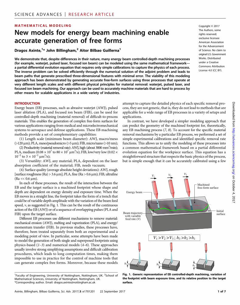
In each of these processes, the result of the interaction between theEB and the target surface is a machined footprint whose shape anddepth are dependent on energy density and exposure time. When theEBmoves in a straight line, the footprint takes the form of a trench thatcould be of variable depth amplitude with the variation of the beam feedspeed, v, as suggested in Fig. 1. This can be the result of the continuousaction of the EB (AWJ) or of a sequence of overlapping pulses (PLA andFIB) upon the target surface.
Different EB processes use different mechanisms to remove material:mechanical erosion (AWJ), melting and vaporization (PLA), and energy/momentum transfer (FIB). In previous studies, these processes have,therefore, been treated separately from both an experimental and amodeling point of view. In particular, some attempts have been madeto model the generation of both single and superposed footprints usingphysics-based (1–3) and numerical models (4–6). These approachesusually involve strong simplifying assumptions and difficult calibrationprocedures, which leads to long computation times, making themimpossible to use in practice for the control of machine tools thatcan generate complex free forms. Moreover, because these models
attempt to capture the detailed physics of each specific removal pro-cess, they are not generic, that is, they do not lead tomethods that areapplicable for a wide range of EB processes in a variety of setups andapplications.
In contrast, we have developed a simpler modeling approach thatcan predict the geometry of the machined footprint for, theoretically,any EB machining process (7, 8). To account for the specific materialremoval mechanisms by a particular EB process, we performed a set ofsimple experimental calibrations and identified specific removal ratefunctions. This allows us to unify the modeling of these processes intoa common mathematical framework based on a partial differentialevolution equation for the workpiece surface. This equation has astraightforward structure that respects the basic physics of the process,but is simple enough that it can be accurately calibrated using a few
Energy beam
Beam trajectory with variable feed rate (V)
V1 V2V3
Machined free-form surface
Initial surface
V1 >V2 >V3 ; h3 >h2 >h1
h1 h2 h3
Fig. 1. Generic representation of EB controlled-depth machining, variation ofthe footprint with beam exposure time, and its relative position to the targetsurface.
1 of 7
SC I ENCE ADVANCES | R E S EARCH ART I C L E
on Octob
http://advances.sciencemag.org/
Dow
nloaded from
initial experiments. Once this has been carried out, single andsuperposed footprint profiles can be determined for any kinematicEB parameters, that is, path, exposure time along the path, and angleof incidence of the EB. This is the direct problem in EB machining. Ifthe path of the EB is selected on the basis of either the intuition andexperience of the end user (craftsmanship) or trial and error, then therecan be a large discrepancy between the actual machined surface and thefree-form surface that is the required outcome of the EB process.
What is needed here is an algorithm for determining the kinematicsof the EB that leads to the required free-form surface. This is the inverseproblem in EB machining. If a complex, free-form shape is to begenerated, themotion of the beammay need to be carried out repeatedly,removing the material in successive layers, depending on the desiredaspect ratio of the free form, while maintaining the original stand-offdistance with each successive layer.
Despite the importance of the inverse problem in the generation offree-form surfaces using time-dependent material removal processes,very few investigations on this topic have been reported. Some approachessimply vary the exposure time of the beam on each pixel of the requiredsurface (9, 10); this is simply the leading order approximation to thenecessary strategy when the radius of the beam is small compared tothe size of the feature that is being etched. However, this does notaccount for either of the nonlinear effects, the detailed shape of thefootprint, nor the effect of the overlapping beam paths. Although itis a plausible starting strategy, particularly for FIB, it is not sufficientfor other EB processes or even, in all situations, for FIB. In addition, aFourier convolution approach to the linearized version of this prob-lem, which does not explicitly take the path of the beam into account,has been studied for abrasive waterjet micromachining, fluid jetpolishing, and ion beam figuring in previous studies (11–14). If thefeatures that need to be machined are comparable to the size of thebeam, a more sophisticated approach is needed.
Some reports on the inverse problem for other time-dependent pro-cesses include the following: electrochemicalmachining (15), where thetool/electrode works in tangential mode to envelope the required sur-face, and electrodischarge machining (16), where the electrode copiesthe geometry of the final surface so that a solution of the inverse prob-
Axinte, Billingham, Bilbao Guillerna, Sci. Adv. 2017;3 : e1701201 22 September 20
lem is not required. We recently reported on a solution of the inverseproblem in AWJ, working in the linear erosion regime to minimize er-rors in the generation of simple two-dimensional shapes (17).
Our research aims to present a unified method of modeling EBmachining that allows us to solve the inverse problem, so that highlyaccurate free forms can be generated independently of the physics thatgoverns the material removal process. Our approach is simple andefficient and requires only modest computing power to produce therequired beam paths and exposure times. We have validated thisapproach using three different EB machining processes: AWJ, PLA,and FIB.
RESULTS AND DISCUSSIONThebasis of ourmathematicalmodel of EBprocesses is that the boundaryof the workpiece evolves as a function of exposure time under the actionof the beam. In particular, only the part of the surface that is beneath thebeam changes at any instant, and the only explicit spatial dependence ofthe rate of material removal is given by a removal rate function, E(r),which depends on the distance from the center of the beam, r, alone.We also assume that the physics of the removal process can bedecomposed into a set of multiplicative functions, which variouslycharacterize the slope dependence, depth dependence, and beam velocity(EB exposure time) dependence of the rate at which the material isremoved. Thenumber and formof these functions vary betweenprocesses,but for each process, there is a simple calibration procedure (8, 18).
We work in a Cartesian coordinate system (x, y, z), with the axis ofthe beamparallel to the z axis (Fig. 2).Wewill assume that the axis of thebeam retains this orientation during the whole machining process. Wealso assume that the workpiece has an initially flat boundary, given byz = Z(x, y, t), with Z(x, y, 0) = 0. The evolution equation is
∂Z∂t
¼ � Eðrðt;uÞÞf1ð∇ZÞf2ðjVjÞf3ðZÞ
where the path of the center of the beam projected onto the (x,y) planeis x =X(t;u), radial position in the beam is r = |x −X(t;u)|, andV ≡ dX
dt
er 4, 2017Fig. 2. Notation used in parameterizing the beam paths.
17 2 of 7
SC I ENCE ADVANCES | R E S EARCH ART I C L E
on October 4, 2017
http://advances.sciencemag.org/
Dow
nloaded from
is the velocity of the beam. The function f1(∇Z)models the dependenceof the rate of removal on the slope of the evolving surface, f2(|V|) thedependence on beam speed, and f3(Z) the dependence on machineddepth, which captures enough the physics of the processes to give anaccurate model. The vector of the control parameters, u, specifies thepath of the beam (as described below).
We briefly summarize how the functions f1, f2, and f3 are calibratedfor each of the three EB processes we have studied. For more details,see the studies of Billingham et al. (7, 8).
(1) For AWJ, f2 = f3 = 1, only the angle of incidence on the surface isfound to nonlinearly affect the process, and the calibration is in twostages. First, the removal rate function, E(r), is determined frommeasurements of a straight, shallow trench machined with constantfeedspeed, for which f1 ≈ 1. Under this approximation, the model islinear, and E(r) can be directly related to the profile across the trench(averaged along the trench to minimize the effect of process noise)through a simple integral. Second, the function f1(∇Z) is determinedbymachining a straight trench along which the beam speed increaseslinearly. A quadratic function of the angle of incidence is found togive excellent results.
(2) For PLA, f1 = f3 = 1, only the feedspeed is found to nonlinearlyaffect the process, and the calibration is again in two stages. First, theremoval rate function, E(r), is calibrated in the same manner as forAWJ. Second, the function f2(|V|) is determined bymachining a straighttrench along which the beam speed increases linearly. For PLA, a linearfunction of the exposure time is the appropriate functional form.
(3) For FIB, f2 = 1, both angle of incidence andmachined depth, butnot beam speed, affect the process. The functional form of f1(∇Z) is wellknown for FIB (19, 20) and is characterized by two parameters. Thefunction f3(Z) is introduced to account for the way FIBmerely damagesthe surface when the beam speed is large, which appears as a skin effectin the results. The function f3(Z) is chosen to be an exponential that tendsto one as Z→ −∞ (away from the skin), which accounts for this effect,and introduces two additional parameters. Because of this skin effect,the simple procedure that allows E(r) to be calibrated in AWJ andPLA does not work. However, E(r) is found experimentally to be closeto Gaussian and can therefore be characterized by two parameters. Themodel parameters can be easily calibrated by machining straighttrenches at several beam speeds and measuring the averaged profileacross each trench.
Although it is natural to write the evolution equation, with time, t, asthe independent variable, it ismore convenient instead touse arc length, s,
Axinte, Billingham, Bilbao Guillerna, Sci. Adv. 2017;3 : e1701201 22 September 20
measured along the beam path. Because ds/dt = |V|, we can write
∂Z∂s
¼ � Dðs;uÞEðrðs;uÞÞf1ð∇ZÞf2ðD�1Þf3ðZÞ
where D ≡ |V|− 1 is the exposure time.For the given beam path parameters, u, the forward problem is to
integrate the evolution equation forward as the beam moves along itspath until s = S(u), where S(u) is the total arclength of the beam path,and to determine the final etched surface, Z(x, y, S;u).
For a given required final etched surface,ZT(x, y), the inverse problemis to find beam path control parameters, u, such that Z(x, y, S(u);u) =ZT(x, y). Partial differential equation–constrained inverse problemslike this, where there are finitely many parameters, u, and an infinitedimensional target, ZT(x, y), need to be formulated as an optimiza-tion problem. We define the cost function, J(u) ≡ ‖Z(x, y, S(u);u) −ZT(x, y)‖
2, and seek to minimize it over the space of possible controlparameters, u.
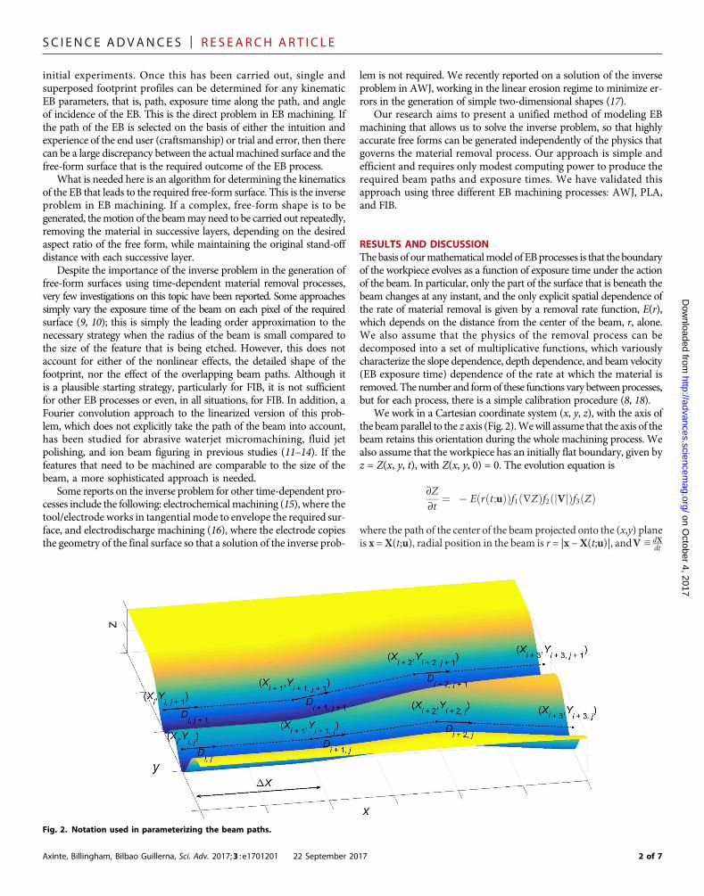
For a complex free-form surface (we will use the Mona Lisa and theBritish penny; Fig. 3), it is likely that the path of the beam that optimallysolves the inverse problem is itself complex. However, practical con-straints imposed by machine dynamics mean that beam paths withsignificant high-frequency components cannot be used (17). Oneapproach to this problem is to use simple raster paths (that is, parallelbeam movements with constant overlapping). For AWJ, paths morecomplex than this are almost impossible to control because of thecomplexity and inertial mass of the machine, but for PLA and FIB,the control and dynamic characteristics of the machines are such thatmore complex paths can be used. We have chosen to use close to raster(small deviations fromparallel) paths to demonstrate our solution of theinverse problem because they are a good compromise betweencomplexity and machinability.
On each of theNp passes, there areNu control points, throughwhichthe beam passes in a piecewise linear manner. At each of these points,(Xi,j, Yi,j), the exposure time is Di,j. This exposure time is also linearlyinterpolated between the control points. This fully specifies the beampath. The distance between consecutive points is chosen to be constantin the x direction, so that
Xi;j ¼ Xi�1;j þ DX for 1 < i ≤ Nu � 1
A BFig. 3. Complex free-form targets used in the experimental trials. The Mona Lisa (A) is relatively smooth compared to the British Penny (B), which has many sharpedges. The heights of the targets have been normalized here.
17 3 of 7
SC I ENCE ADVANCES | R E S EARCH ART I C L E
on October 4, 2017
http://advances.sciencemag.org/
Dow
nloaded from
A B
C D
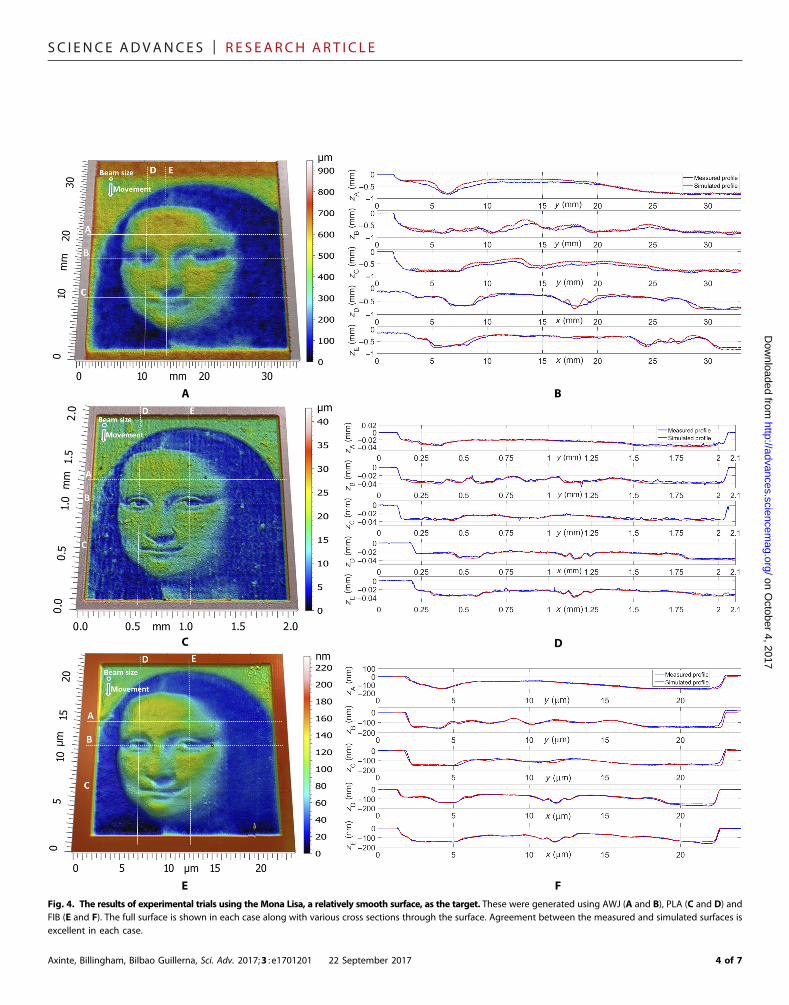
E FFig. 4. The results of experimental trials using the Mona Lisa, a relatively smooth surface, as the target. These were generated using AWJ (A and B), PLA (C and D) andFIB (E and F). The full surface is shown in each case along with various cross sections through the surface. Agreement between the measured and simulated surfaces isexcellent in each case.
Axinte, Billingham, Bilbao Guillerna, Sci. Adv. 2017;3 : e1701201 22 September 2017 4 of 7

SC I ENCE ADVANCES | R E S EARCH ART I C L E
The beam path parameter vector, u, is therefore composed of theexposure time at each control point and (unless straight raster pathsare used) the y coordinate of each control point, so that
u ¼ ðY0;0;D0;0;Y1;0;D1;0;Y2;0;D2;0;…;YNu�1;Np�1;DNu�1;Np�1Þ
The first subscript, 1≤ i≤Nu, denotes the ith control point for eachraster pass, and the second subscript, 1≤ j≤ Np, indicates the jth pass,so there are 2NpNu control parameters in the most general case.
Axinte, Billingham, Bilbao Guillerna, Sci. Adv. 2017;3 : e1701201 22 September 20
The forward problem is
∂Z∂s
¼ � Dðs;uÞEðrðs;uÞÞf1ð∇ZÞf2ðDÞf3ðZÞ
subject to Z(x, y, 0;u) = 0, for 0≤ s≤ S(u). For a given u, and hence agiven beam path and exposure time as a function of arc length, asimple, central finite difference scheme with explicit Euler arc-lengthstepping and a uniform Cartesian grid is sufficient to accurately
on October 4, 2017
http://advances.sciencemag.org/
Dow
nloaded from
A B
C DFig. 5. The results of experimental trials using the British Penny, a surface with many sharp edges, as the target surface. These were generated using PLA (A and B)and FIB (C and D), with either straight (A and C) or nonstraight (B and D) paths. The dynamics of the bulky AWJ machine preclude the use of nonstraight paths formachining. In each case, nonstraight paths result in a more accurate free-form.
A BFig. 6. Details of a surface with many sharp edges generated by nonstraight beam paths using PLA (A) and FIB (B). In each case, note that the beam follows the sharpedges. As a consequence of this, the use of nonstraight passes improves the accuracy of the machining mainly in the neighbourhood of the sharp edges.
17 5 of 7
SC I ENCE ADVANCES | R E S EARCH ART I C L E
on October 4, 2017
http://advances.sciencemag.org/
Dow
nloaded from
compute Z(x, y, S(u);u), the final etched surface, and hence the costfunction
JðuÞ ≡ jjZðx; y; SðuÞ;uÞ � ZTðxyÞjj2
The inverse problem, namely, to find a set of control parameters,u*, such that
Jðu*Þ ≤ JðuÞ ∀u∈U
whereU is the set of possible control parameter vectors, could be tackledusing a wide range of different optimization algorithms. A key point isthat we know that a simple pixel-by-pixel approach with straight rasterpaths and exposure time proportional to the required depth of removalgives a final etched profile that is reasonably close to the target surface.This means that we have a good initial estimate of u, so that a simplegradient-based approach is able to locate a local minimum of J(u),which is in good agreement with the target surface, although we cannotguarantee that this is a global minimum.
To implement gradient-based optimization, we need an efficientway to calculate the gradient matrix, ∂J/∂u. Because there are typicallyseveral thousand control parameters in u, the obvious, finite differenceapproach is prohibitively expensive. Instead, we solve the discreteadjoint to the finite difference solver for the forwardproblem to efficientlyevaluate the gradient. The uniform-grid, explicit Euler finite differenceapproach is simple enough that we can calculate the adjoint finitedifference scheme by hand. This consists of another evolution problemthatmust be integrated backward along the beampath. This calculation isof comparable computational complexity to the calculation of J(u) in theforward problem and gives us a very efficient means of calculating thegradient at each step of the optimization.
We have used this methodology to generate free forms on variousmaterials using AWJ, PLA, and FIB as EBmachining processes (see theMaterials and Methods for more details). We will illustrate our resultsusing complex free forms, namely, the Mona Lisa (a smooth surface)(Fig. 3A) and the British Penny coin (a surface with various sharp edgeswith different orientations) (Fig. 3B).
For each surface, we show results with straight raster beam paths,and to demonstrate that we can obtain significantly better results forsurfaces with sharp edges, we also used nonstraight raster paths forthe Penny coin.Note also that forAWJ,wewere able to use only straightpaths due to practical constraints imposed bymachine dynamics, so weonly present the results for the Mona Lisa.
Figure 4 shows theMonaLisa, a typical smooth surface, generated byAWJ (Fig. 4A), PLA (Fig. 4B), andFIB (Fig. 4C) using straight raster paths.The noise inherent in AWJ machining, due to the complex multiphaseturbulent fluid flow in the jet and its interactions with the target surface aswell as thedynamics of themachine, leads to a significantly less accurate free-form generation with less high-frequency content (small-scale features). Inaddition, deviations from the required profiles on different cross sections(A, B, C, D, and E) are presented for each process in Fig. 4 (D to F).
Note that the nature of the deviations depends on the orientation ofthe cross section relative to the raster path. This effect can be observedmore on the cross sections A, B, and C of the AWJ machined surface(Fig. 4A) that present higher deviations from the simulated profile. Thisis caused by the lateral step-over of the beam and the interaction ofadjacent trenches, which is more prone to secondary effects that areless well captured by the model. In contrast, for the cross sections DandE, the errors are significantly smaller because they are in the direction
Axinte, Billingham, Bilbao Guillerna, Sci. Adv. 2017;3 : e1701201 22 September 20
ofmotionof thebeam.Figure 4 (CandD) shows that the targetmachinedusing PLA is somewhat closer in detail to the required surface than thatmachined using eitherAWJ or FIB (see Fig. 4, E and F). This is not due tothe error in themachined surfaces themselves, but rather the fact that ourmodel for FIB is inherently nonlinear owing to the skin effect, whichmeans that our algorithm produces simulated surfaces that are signif-icantly less accurate for FIB than for PLA.
Figure 5 shows the British Penny, a typical surface with sharp edgesat different orientations, generated by PLA (Fig. 5A) and FIB (Fig. 5C)using straight raster paths and Fig. 5B and Fig. 5D show results usingnonstraight raster paths. It is clear that the nonstraight paths are able tomore accurately capture the sharpness of the various edges, which dem-onstrates the utility of our approach.Details of the surfaces generated bynonstraight passes are presented in Fig. 6, where it can be observed thatthe beam follows the edges of the free form, thus resulting in a betterdefinition of the surface.
CONCLUSIONSWehave developed a simple genericmodeling approach and algorithmsfor the inverse problem to generate free-form surfaces using differentEB machining processes and various workpiece target materials. Thismodeling approach is able to embed the physics of the diverse rangeof material removal mechanisms encountered in EB processing usingsimple experimental calibration. The accuracy of the approach has beendemonstrated by low average relative errors (AWJ, 10 to 20%; PLA, 6 to8%; FIB, 4 to 6%) from the required surfaces. Being a time-dependentmodeling framework, our approach is sensitive to the constraints of themachine dynamics that could limit the system response to sudden changesof the feed speed required to generate the free forms; the limitationsimposedby themachinedynamicshavebeenput in evidenceby generatingwith AWJ only on smooth surfaces (for example, Mona Lisa) rather thansharp-edged surfaces, which requires sharp changes of the EB feed speed.Hence, our modeling framework needs to be accompanied by appropriatecharacterization and modeling of the dynamics of the EB machiningsystem.Althoughhere onlypiecewise linearEBpathshave been investigated,future work could be extended to understand the influence of morecomplex paths (for example, circular and spiral) on the accuracy ofthe machined free forms.
MATERIALS AND METHODSThe proposed modeling approach and the efficient solution fordetermining the inverse solution were validated on three EB processes/machines characterized by different material removal mechanisms,working principles, and dynamics:
(1)Waterjetmachining (AWJ) as a continuousmacro (beamdiameter,500 mm) attrition-based material removal process. A Microwaterjet 3-axisF4 type (WaterjetAG),with jet positioning accuracy <0.003mm, equippedwith an orifice 0.18 mm in diameter and a focussing tube 0.5 mm indiameter operating at 3500-bar (KMT streamline SL-V100D) pumppressure was used. Using a constant nozzle-to-surface stand-off distanceof 3 mm, the jet feed speeds were varied, in accordance with the solutionof the inverse problem, between 200 and 600 mm/min. Considering theability of the process to machine difficult-to-cut materials, Ti6Al4V, analloy extensively used in aerospace andmedical industries,was used as thetarget workpiece for AWJ.
(2) PLA as a discontinuous meso (beam diameter, 45 mm) melting/vaporization-based material removal process. A pulsed (1 to 35 kHz)
17 6 of 7
SC I ENCE ADVANCES | R E S EARCH ART I C L E
on http://advances.sciencem
ag.org/D
ownloaded from
SPI-G3 HM fiber laser using an Aerotech AGV-10HP galvanometerwas used to manipulate the beam, with the feed speed varying between4 and 25 mm/s as per the solution of the inverse problem, on two axes.An f-q lens (100-mm focal length) was used to focus the beam on afour-axis Aerotech ACS-150-135 machining table on which we set aflat graphite (POCO AF-5) target material. Using this setup, a beamwith an average diameter of 0.045 mm (ellipticity, 0.956) and ameasured (Thorlabs PM100D) power of 18.8 W was obtained.
(3) FIB as a micro (nominal beam diameter of 100 nm) momentum-based material removal process was performed using an FEI HeliosNanoLab 600 system with a Ga+ LMIS (liquid metal ion source) operatedwith a beam energy of 30 keV and current of 6.5 nA. The FIB chamberpressure was maintained in the order of 10−6 mbar during the irradiation.The single crystalline boron p-doped Si substrate with resistivity of 11 to12 W·cm was cleaned in an ultrasonic bath using acetone, isopropanoland deionized water for 10min and dried with nitrogen gas. Tominimizeredeposition in the experimental tests, the maximum aspect ratio of themachined structure was kept below 1.
For the free forms generated by AWJ and PLA, a Bruker GT-Iwhite light interferometer (pixel size of 197 nm) was used, whereasthe FIB free form was measured with an atomic force microscopeusing a Bruker Icon Dimension in tapping mode. As an initial free-formsurface to demonstrate our models, we chose the Mona Lisa for itsvarious gradients, which was scaled accordingly: AWJ (30 × 30 ×0.8 mm3) (Fig. 4A); PLA (1.865 × 1.865 × 0.04 mm3) (Fig. 4C); FIB(20 × 20 × 0.175 mm3) (Fig. 4E). This scaled free form was used todemonstrate the accuracy of the solution of the inverse problem withstraight beam paths parallel to the y axis.
To further demonstrate the accuracy of the solution of the inverseproblem using nonstraight beam paths, we generated a free form withsharp gradients, namely, the British one penny coin, usingPLA (Fig. 5B)and FIB (Fig. 5D), with details presented in Fig. 6, A and B, respectively.This free form was not generated by AWJ because the machining headhas high inertia, which is not be able to respond to the fast commandsneeded to generate the nonstraight paths.
October 4, 2017
REFERENCES AND NOTES1. M. EITobgy, E.-G. Ng, M. A. Elbestawi, Modelling of abrasive waterjet machining: A new
approach. CIRP Ann.-Manuf. Techn. 54, 285–288 (2005).2. H. D. Vora, S. Santhanakrishnan, S. P. Harimkar, S. K. S. Boetcher, N. B. Dahotre,
One-dimensional multipulse laser machining of structural alumina: Evolution of surfacetopography. Int. J. Adv. Manuf. Technol. 68, 69–83 (2013).
3. T. Ishitani, T. Ohnishi, Modeling of sputtering and redeposition in focused-ion-beamtrench milling. J. Vac. Sci. Technol. A 9, 3084–3089 (1991).
4. S. Anwar, D. A. Axinte, A. A. Becker, Finite element modelling of abrasive waterjet milledfootprints. J. Mater. Process. Technol. 213, 180–193 (2013).
5. J. Lee, J. Yoo, K. Lee, Numerical simulation of the nano-second pulsed laser ablationprocess based on the finite element thermal analysis. J. Mech. Sci. Technol. 28, 1797–1802(2014).
Axinte, Billingham, Bilbao Guillerna, Sci. Adv. 2017;3 : e1701201 22 September 20
6. M. F. Russo Jr., M. Maazouz, L. A. Giannuzzi, C. Chandler, M. Utlaut, B. J. Garrison,Gallium-induced milling of silicon: A computational investigation of focused ion beams.Microsc. Microanal. 14, 315–320 (2008).
7. J. Billingham, C. B. Miron, D. A. Axinte, M. C. Kong, Mathematical modelling of abrasivewaterjet footprints for arbitrarily moving jets: Part II—Overlapped single and multiplestraight paths. Int. J. Mach. Tool Manuf. 68, 30–39 (2013).
8. G. B. J. Cadot, D. A. Axinte, J. Billingham, Continuous trench, pulsed laser ablation formicro-machining applications. Int. J. Mach. Tool Manuf. 107, 8–20 (2016).
9. Y. Fu, N. K. A. Bryan, Fabrication of three-dimensional microstructures by two-dimensional slice by slice approaching via focused ion beam milling. J. Vac. Sci. Technol. B22, 1672–1678 (2004).
10. D. P. Adams, M. J. Vasile, Accurate focused ion beam sculpting of silicon using a variablepixel dwell time approach. J. Vac. Sci. Technol. B 24, 836–844 (2006).
11. M. R. Sookhak Lari, M. Papini, Inverse methods to gradient etch three-dimensionalfeatures with prescribed topographies using abrasive jet micro-machining:Part I – Modeling. Precis. Eng. 45, 272–284 (2016).
12. M. R. Sookhak Lari, M. Papini, Inverse methods to gradient etch three-dimensionalfeatures with prescribed topographies using abrasive jet micro-machining:Part II—Verification with micro-machining experiments. Precis. Eng. 45, 262–271 (2016).
13. H. Fang, P. Guo, J. Yu, Dwell function algorithm in fluid jet polishing. Appl. Optics 45,4291–4296 (2006).
14. J. F. Wu, Z. W. Lu, H. X. Zhang, T. S. Wang, Dwell function algorithm in ion beam figuring.Appl. Optics 48, 3930–3937 (2009).
15. P. Domanowski, Inverse problems of shaping by electrochemical generating machining.J. Mater. Process. Technol. 109, 347–353 (2001).
16. M. Kunieda, Y. Kaneko, W. Natsu, Reverse simulation of sinking EDM applicable to largecurvatures. Precis. Eng. 36, 238–243 (2012).
17. A. Bilbao Guillerna, D. Axinte, J. Billingham, The linear inverse problem in energy beamprocessing with an application to abrasive waterjet machining. Int. J. Mach. Tool Manuf.99, 34–42 (2015).
18. M. C. Kong, S. Anwar, J. Billingham, D. A. Axinte, Mathematical modelling of abrasivewaterjet footprints for arbitrarily moving jets: Part I—Single straight paths. Int. J. Mach.Tool Manuf. 53, 58–68 (2012).
19. X. Xu, A. D. Della Ratta, J. Sosonkina, J. Melngailis, Focused ion beam induced depositionand ion milling as a function of angle of ion incidence. J. Vac. Sci. Technol. B 10,2675–2680 (1992).
20. Y. Yamamura, Y. Itikawa, N. Itoh, “Angular dependence of sputtering yields of monatomicsolids” (IPPJ-AM report 26, Nagoya University, 1983).
AcknowledgmentsFunding: This work was supported by the Engineering and Physical Sciences ResearchCouncil [grant number EP/K02826X/1]. We would also like to thank M. Rommel of theFraunhofer Institute for Integrated Systems and Device Technology, Erlangen, Germany,for using FIB to generate free forms and then measuring them to validate our modelingframework. Author contributions: D.A. and J.B. developed the generic concept of themodeling framework. All the authors developed the models, designed the experiments,and discussed and analyzed the results. A.B.G. performed the experiments. A.B.G. and D.A.prepared the figures. D.A. and J.B. prepared the manuscript. Competing interests: Theauthors declare that they have no competing interests. Data and materials availability: Alldata needed to evaluate the conclusions in the paper are present in the paper. Additionaldata related to this paper may be requested from the authors.
Submitted 14 April 2017Accepted 29 August 2017Published 22 September 201710.1126/sciadv.1701201
Citation: D. Axinte, J. Billingham, A. Bilbao Guillerna, New models for energy beam machiningenable accurate generation of free forms. Sci. Adv. 3, e1701201 (2017).
17 7 of 7
New models for energy beam machining enable accurate generation of free formsDragos Axinte, John Billingham and Aitor Bilbao Guillerna
DOI: 10.1126/sciadv.1701201 (9), e1701201.3Sci Adv
ARTICLE TOOLS http://advances.sciencemag.org/content/3/9/e1701201
REFERENCES
http://advances.sciencemag.org/content/3/9/e1701201#BIBLThis article cites 19 articles, 0 of which you can access for free
PERMISSIONS http://www.sciencemag.org/help/reprints-and-permissions
Terms of ServiceUse of this article is subject to the
registered trademark of AAAS.is aScience Advances Association for the Advancement of Science. No claim to original U.S. Government Works. The title
York Avenue NW, Washington, DC 20005. 2017 © The Authors, some rights reserved; exclusive licensee American (ISSN 2375-2548) is published by the American Association for the Advancement of Science, 1200 NewScience Advances
on October 4, 2017
http://advances.sciencemag.org/
Dow
nloaded from