axl f ai4 u 1h - digi-key sheets/phoenix contact pdfs/axl_f... · axl f ai4 u 1h 8659_en_03 phoenix...
TRANSCRIPT

1 Description
Axioline F analog input module, 4 voltage inputs,
integrated sensor supply
AXL F AI4 U 1H
© PHOENIX CONTACT
Data sheet
Valid from firmware version 1.10.
The module is designed for use within an Axioline F station.
It is used to acquire analog voltage signals.
Features
– 4 analog, bipolar input channels for the connection of
voltage signals
– Connection of sensors in 2, 3, and 4-wire technology
– Voltage ranges: 0 V ... 10 V, ±10 V, 0 V ... 5 V, ±5 V
– Simultaneous scanning of all channels by means of si-
multaneous sampling
– High crosstalk attenuation between the channels,
thanks to separate signal paths
– Particularly robust against electromagnetic interference
– Device type label stored
– Diagnostic and status indicators
This data sheet is only valid in association with the UM EN AXL F SYS INST user manual.
Make sure you always use the latest documentation.
It can be downloaded from the product at phoenixcontact.net/products.
8659_en_03 2015-10-22

AXL F AI4 U 1H
8659_en_03 PHOENIX CONTACT 2
2 Table of contents
1 Description .............................................................................................................................. 1
2 Table of contents ..................................................................................................................... 2
3 Ordering data .......................................................................................................................... 3
4 Technical data ......................................................................................................................... 3
5 Tolerance data......................................................................................................................... 6
6 Internal circuit diagram ............................................................................................................ 7
7 Terminal point assignment....................................................................................................... 8
8 Connection examples.............................................................................................................. 8
9 Connection notes .................................................................................................................... 9
10 Local status and diagnostic indicators ................................................................................... 10
11 Process data.......................................................................................................................... 11
12 Significant values in various formats...................................................................................... 12
12.1 Significant values in IB IL format ............................................................................................ 12
12.2 Significant values in S7-compatible format ............................................................................... 12
13 Parameter, diagnostics and information (PDI) ....................................................................... 13
14 Standard objects ................................................................................................................... 14
14.1 Objects for identification (device rating plate)............................................................................ 14
14.2 Object for multilingual capacity.............................................................................................. 15
14.3 Object descriptions ............................................................................................................ 15
14.4 Diagnostics objects ............................................................................................................ 15
14.5 Objects for process data management.................................................................................... 17
14.6 Objects for device management ............................................................................................ 18
15 Application objects ................................................................................................................ 19
15.1 Parameter table (0080hex: ParaTable).................................................................................... 19
15.2 Measured value in extended float format
(0082hex: Measured Value Float)........................................................................................... 20
15.3 Minimum process data value
(0083hex: PD Min).............................................................................................................. 21
15.4 Maximum process data value
(0084hex: PD Max) ............................................................................................................. 21
16 Device descriptions ............................................................................................................... 21

AXL F AI4 U 1H
8659_en_03 PHOENIX CONTACT 3
Description Type Order No. Pcs./Pkt.
Axioline F analog input module, 4 inputs: 0 - 5 V, ±5 V, 0 - 10 V, ±10 V,
2, 3, and 4-conductor connection technology, integrated sensor supply
(including bus base module and connectors)
AXL F AI4 U 1H 2688501 1
3 Ordering data
Accessories Type Order No. Pcs./Pkt.
Axioline F bus base module for housing type H (Replacement item) AXL F BS H 2700992 5
Axioline shield connection set (contains 2 busbar holders and 2 SK 5 shield
connection clamps)
AXL SHIELD SET 2700518 1
Zack marker strip for Axioline F (device labeling), in 2 x 20.3 mm pitch, un-
printed, 25-section, for individual labeling with B-STIFT 0.8, X-PEN, or
CMS-P1-PLOTTER (Marking)
ZB 20,3 AXL UNPRINTED 0829579 25
Zack marker strip, flat, in 10 mm pitch, unprinted, 10-section, for individual
labeling with M-PEN 0,8, X-PEN, or CMS-P1-PLOTTER (Marking)
ZBF 10/5,8 AXL UNPRINTED 0829580 50
Insert label, Roll, white, unlabeled, can be labeled with: THERMOMARK
ROLL, THERMOMARK ROLL X1, THERMOMARK X, THERMOMARK
S1.1, Mounting type: snapped into marker carrier, Lettering field: 35 x 28
mm (Marking)
EMT (35X28)R 0801602 1
Documentation Type Order No. Pcs./Pkt.
User manual, English, Axioline F: System and installation UM EN AXL F SYS INST - -
User manual, English, Axioline F: Diagnostic registers, and error messages UM EN AXL F SYS DIAG - -
Dimensions (nominal sizes in mm)
Width 35 mm
Height 126.1 mm
Depth 54 mm
Note on dimensions The depth is valid when a TH 35-7.5 DIN rail is used (according to EN 60715).
4 Technical data
35 54
12
2,4
12
6,1
General data
Color traffic grey A RAL 7042
Weight 145 g (with connectors and bus base module)
Ambient temperature (operation) -25 °C ... 60 °C
Ambient temperature (storage/transport) -40 °C ... 85 °C
AXL F AI4 U 1H
8659_en_03 PHOENIX CONTACT 4
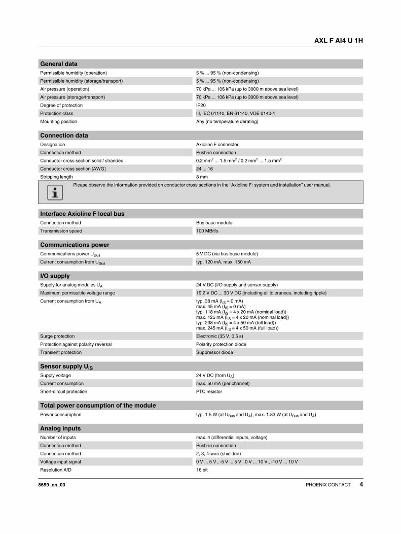
Permissible humidity (operation) 5 % ... 95 % (non-condensing)
Permissible humidity (storage/transport) 5 % ... 95 % (non-condensing)
Air pressure (operation) 70 kPa ... 106 kPa (up to 3000 m above sea level)
Air pressure (storage/transport) 70 kPa ... 106 kPa (up to 3000 m above sea level)
Degree of protection IP20
Protection class III, IEC 61140, EN 61140, VDE 0140-1
Mounting position Any (no temperature derating)
General data
Connection data
Designation Axioline F connector
Connection method Push-in connection
Conductor cross section solid / stranded 0.2 mm² ... 1.5 mm² / 0.2 mm² ... 1.5 mm²
Conductor cross section [AWG] 24 ... 16
Stripping length 8 mm
Please observe the information provided on conductor cross sections in the “Axioline F: system and installation” user manual.
Interface Axioline F local bus
Connection method Bus base module
Transmission speed 100 MBit/s
Communications power
Communications power UBus 5 V DC (via bus base module)
Current consumption from UBus typ. 120 mA, max. 150 mA
I/O supply
Supply for analog modules UA 24 V DC (I/O supply and sensor supply)
Maximum permissible voltage range 19.2 V DC ... 30 V DC (including all tolerances, including ripple)
Current consumption from UA typ. 38 mA (IiS = 0 mA)
max. 45 mA (IiS = 0 mA)
typ. 118 mA (IiS = 4 x 20 mA (nominal load))
max. 125 mA (IiS = 4 x 20 mA (nominal load))
typ. 238 mA (IiS = 4 x 50 mA (full load))
max. 245 mA (IiS = 4 x 50 mA (full load))
Surge protection Electronic (35 V, 0.5 s)
Protection against polarity reversal Polarity protection diode
Transient protection Suppressor diode
Sensor supply UiS
Supply voltage 24 V DC (from UA)
Current consumption max. 50 mA (per channel)
Short-circuit protection PTC resistor
Total power consumption of the module
Power consumption typ. 1.5 W (at UBus and UA), max. 1.83 W (at UBus and UA)
Analog inputs
Number of inputs max. 4 (differential inputs, voltage)
Connection method Push-in connection
Connection method 2, 3, 4-wire (shielded)
Voltage input signal 0 V ... 5 V , -5 V ... 5 V , 0 V ... 10 V , -10 V ... 10 V
Resolution A/D 16 bit

AXL F AI4 U 1H
8659_en_03 PHOENIX CONTACT 5
A/D conversion time 31.25 µs
Limit frequency (3 dB) 30 Hz , 12 kHz
Measured value representation 16 bits (15 bits + sign bit)
Data formats IB IL, S7-compatible
Process data update 160 µs
Input filter 30 Hz, 12 kHz and mean-value generation (can be parameterized)
Precision 0.1 % (of measuring range final value for active mean-value generation and 30 Hz
filter)
Transient protection of inputs Suppressor diode
Input resistance of voltage input 268 kΩ (typical)
Common mode voltage range signal - ground -50 V DC ... 50 V DC
Overload protection ±30 V DC, maximum
Analog inputs
Configuration and parameter data in a PROFIBUS system
Required parameter data 7 Byte
Need for configuration data 6 Byte
Electrical isolation/isolation of the voltage areas
Test section Test voltage
5 V communications power (logic), 24 V supply (I/O) 500 V AC, 50 Hz, 1 min
5 V supply (logic)/analog inputs 500 V AC, 50 Hz, 1 min
5 V supply (logic)/functional earth ground 500 V AC, 50 Hz, 1 min
24 V supply (I/O)/analog inputs 500 V AC, 50 Hz, 1 min
24 V supply (I/O) / functional earth ground 500 V AC, 50 Hz, 1 min
Analog inputs/functional earth ground 500 V AC, 50 Hz, 1 min
Mechanical tests
Vibration resistance in acc. with EN 60068-2-6/IEC 60068-2-6 5g
Shock in acc. with EN 60068-2-27/IEC 60068-2-27 30g
Continuous shock according to EN 60068-2-27/IEC 60068-2-27 10g
Conformance with EMC Directive 2004/108/EC
Noise immunity test in accordance with EN 61000-6-2
Electrostatic discharge (ESD) EN 61000-4-2/IEC 61000-4-2 Criterion B; 6 kV contact discharge, 8 kV air discharge
Electromagnetic fields EN 61000-4-3/IEC 61000-4-3 Criterion A; Field intensity: 10 V/m
Fast transients (burst) EN 61000-4-4/IEC 61000-4-4 Criterion B, 2 kV
Transient surge voltage (surge) EN 61000-4-5/IEC 61000-4-5 Criterion B; supply lines DC: ±0.5 kV/±0.5 kV (symmetrical/asymmetrical); ±1 kV
to shielded I/O cables
Conducted interference EN 61000-4-6/IEC 61000-4-6 Criterion A; Test voltage 10 V
Noise emission test according to EN 61000-6-3
Radio interference properties EN 55022 Class B
Approvals
For the latest approvals, please visit phoenixcontact.net/products.
AXL F AI4 U 1H
8659_en_03 PHOENIX CONTACT 6
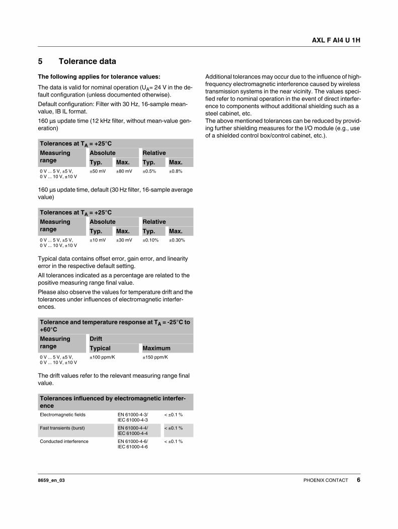
5 Tolerance data
The following applies for tolerance values:
The data is valid for nominal operation (UA= 24 V in the de-
fault configuration (unless documented otherwise).
Default configuration: Filter with 30 Hz, 16-sample mean-
value, IB IL format.
160 μs update time (12 kHz filter, without mean-value gen-
eration)
160 μs update time, default (30 Hz filter, 16-sample average
value)
Typical data contains offset error, gain error, and linearity
error in the respective default setting.
All tolerances indicated as a percentage are related to the
positive measuring range final value.
Please also observe the values for temperature drift and the
tolerances under influences of electromagnetic interfer-
ences.
The drift values refer to the relevant measuring range final
value.
Additional tolerances may occur due to the influence of high-
frequency electromagnetic interference caused by wireless
transmission systems in the near vicinity. The values speci-
fied refer to nominal operation in the event of direct interfer-
ence to components without additional shielding such as a
steel cabinet, etc.
The above mentioned tolerances can be reduced by provid-
ing further shielding measures for the I/O module (e.g., use
of a shielded control box/control cabinet, etc.).
Tolerances at TA = +25°C
Measuring
range
Absolute Relative
Typ. Max. Typ. Max.
0 V ... 5 V, ±5 V,
0 V ... 10 V, ±10 V
±50 mV ±80 mV ±0.5% ±0.8%
Tolerances at TA = +25°C
Measuring
range
Absolute Relative
Typ. Max. Typ. Max.
0 V ... 5 V, ±5 V,
0 V ... 10 V, ±10 V
±10 mV ±30 mV ±0.10% ±0.30%
Tolerance and temperature response at TA = -25°C to
+60°C
Measuring
range
Drift
Typical Maximum
0 V ... 5 V, ±5 V,
0 V ... 10 V, ±10 V
±100 ppm/K ±150 ppm/K
Tolerances influenced by electromagnetic interfer-
ence
Electromagnetic fields EN 61000-4-3/
IEC 61000-4-3
< ±0.1 %
Fast transients (burst) EN 61000-4-4/
IEC 61000-4-4
< ±0.1 %
Conducted interference EN 61000-4-6/
IEC 61000-4-6
< ±0.1 %
AXL F AI4 U 1H
8659_en_03 PHOENIX CONTACT 7
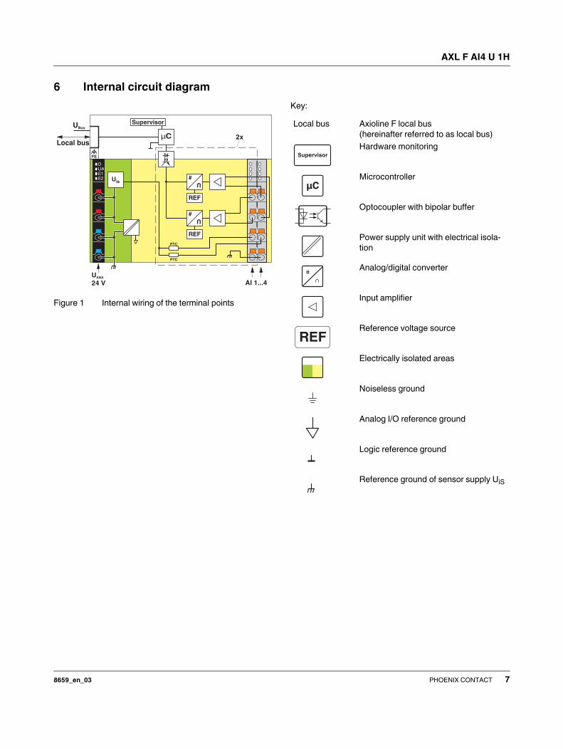
6 Internal circuit diagram
Figure 1 Internal wiring of the terminal points
Key:
DUAE1E2
2x
AI 1...4U
24 VANA
UBus
Local busμC
#
U
REF
#
U
REF
Supervisor
FE
Uis
PTC
PTC
Local bus Axioline F local bus
(hereinafter referred to as local bus)
Hardware monitoring
Microcontroller
Optocoupler with bipolar buffer
Power supply unit with electrical isola-
tion
Analog/digital converter
Input amplifier
Reference voltage source
Electrically isolated areas
Noiseless ground
Analog I/O reference ground
Logic reference ground
Reference ground of sensor supply UiS
Supervisor
µC
REF

AXL F AI4 U 1H
8659_en_03 PHOENIX CONTACT 8
7 Terminal point assignment
Figure 2 Terminal point assignment
8 Connection examples
Figure 3 Connector for voltage measurement
Figure 4 Connection of potentiometric position sensors
The values of potentiometric position sensors can be ac-
quired with voltage measurement. Supply the potentiometer
via an external power supply unit (Uext = 10 V).
Figure 5 Differential voltage input with active 3-wire
transmitter
Terminal
point
Color Assignment
Supply voltage input
a1, a2 Red 24 V DC
(UA)
Supply for analog mod-
ules (bridged internally)
b1, b2 Blue GND Reference potential of
the supply voltage (inter-
nally jumpered)
Analog inputs
00 ... 03 Orange U1+ ...
U4+
Positive voltage connec-
tion for channel 1 ... 4
10 ... 13 Orange U1- ...
U4-
Negative voltage con-
nection for channel 1 ... 4
20 ... 23 Orange UiS1 ...
UiS4
24 V sensor supply for
channel 1 ... 4
30 ... 33 Orange GND Reference potential of
sensor supply
0300131023203330
a1
a2
b1
b2
00
10
20
30
01
11
21
31
02
12
22
32
03
13
23
33
a1a2b1b2
00
10
20
30
01
11
21
31
02
12
22
32
03
13
23
33
a1
a2
b1
b2
U U
GNDP
U+24 VU
00
10
20
30
01
11
21
31
+–
Uext
00
10
20
30
01
11
21
31
P
U
+24 V
GND

AXL F AI4 U 1H
8659_en_03 PHOENIX CONTACT 9
9 Connection notes
Connect the cable shield to functional earth immediately
after the cables enter the control cabinet.
If there is no closed control cabinet, connect the shield to a
shield bus.
Use the AXL SHIELD SET Axioline shield connection set for
an optimized connection directly in front of the module.
NOTE: Damage to the electronics/mea-
suring errors
Always connect the analog actuators using
shielded twisted-pair cables.
Unshielded cables may lead to values outside
the specified tolerance limits in environments
subject to heavy noise.
For further information on shielding, please
refer to the UM EN AXL SYS INST user man-
ual.

AXL F AI4 U 1H
8659_en_03 PHOENIX CONTACT 10
10 Local status and diagnostic indicators
Figure 6 Local status and diagnostic indicators
30
20
10
00
32
22
12
02
31
21
11
01
33
23
13
03D
UA
E1
E2
Channel errors are errors that can be associ-
ated with a channel.
Periphery errors are errors that affect the en-
tire module.
Designa-
tion
Color Meaning State Description
D Red/yel-
low/green
Diagnostics of local bus communication
Run Green ON The device is ready for operation, communication within the station
is OK.
All data is valid. There are no faults.
Active Green
flashing
The device is ready for operation, communication within the station
is OK.
The data is not valid. Valid data from the controller/higher-level net-
work not available.
There is no fault in the module.
Device applica-
tion not active
Flashing
green/yel-
low
The device is ready for operation, communication within the station
is OK.
Output data cannot be outputted and/or input data cannot be
read.
There is a fault on the periphery side of the module..
Ready Yellow ON The device is ready for operation but did not detect a valid cycle
after power-on.
Connected Yellow
flashing
The device is not (yet) part of the active configuration.
Reset Red ON The device is ready for operation but has lost the connection to the
bus head.
Not connected Flashing
red
The device is ready for operation but there is no connection to the
previously existing device.
Power down OFF Device in (power) reset.
UA Green UAnalog ON Supply for analog modules UA present.
OFF Supply for analog modules UA not present.
E1 Red Supply voltage
error
ON Supply for analog modules UA is faulty.
OFF Supply for analog modules UA is OK.
E2 Red Error ON I/O or channel error has occurred.
OFF No error

AXL F AI4 U 1H
8659_en_03 PHOENIX CONTACT 11
Error code and status of the E1 and E2 LEDs 11 Process data
The module uses four words of IN process data.
Each channel is mapped to a word.
Input words IN0 to IN3
The measured values are transmitted to the controller board
or the computer using process data input words IN0 to IN3.
The measured values are depicted in IB IL or S7-compatible
format. In both cases, the measured value is displayed in
16 bit format. The data type is Integer 16 from a technical
programming point of view.
In the IB IL format a diagnostic code is mapped to the input
data in the event of an error.
Error E1 LED E2 LED
No error OFF OFF
Underrange OFF ON
Overrange OFF ON
Supply voltage faulty (supply for
analog modules UA)
ON ON
Parameter table invalid OFF ON
Device error OFF ON
Flash format error OFF ON
The error that can actually be reported de-
pends on the measuring range. For additional
information please refer to the tables with sig-
nificant measured values in various formats.
15 14 13 12 11 10 9 8 7 6 5 4 3 2 1 0
Analog value
Code
(hex)
Cause
8001 Measuring range exceeded (overrange)
8004 Measured value invalid/no valid measured
value available
8020 Supply voltage faulty (supply for analog mod-
ules UA)
8040 Device faulty
8080 Below measuring range (underrange)

AXL F AI4 U 1H
8659_en_03 PHOENIX CONTACT 12
12 Significant values in various formats
12.1 Significant values in IB IL format
The maximum measured value is 7F00hex.
Depending on the measuring range, the minimum measured value is either 0000hex or 8100hex.
12.2 Significant values in S7-compatible format
The maximum measured value is 7EFFhex.
Depending on the measuring range, the minimum measured value is either 0000hex or 8100hex.
Input data 0 V ... 10 V ± 10 V 0 V ... 5 V ± 5 V
hex dec V V V V
8001 Overrange > +10.837 > +10.837 > +5.419 > +5.419
7F00 32512 +10.837 +10.837 +5.419 +5.419
7530 30000 +10.0 +10.0 +5.0 +5.0
0001 1 +333.33 μV +333.33 μV +166.67 μV +166.67 μV
0000 0 ≤ 0 0 ≤ 0 0
FFFF -1 -333.33 μV -166.67 μV
8AD0 -30000 -10.0 -5.0
8100 -32512 -10.837 -5.419
8080 Underrange < -10.837 < -5.419
Input data 0 V ... 10 V ± 10 V 0 V ... 5 V ± 5 V
hex dec V V V V
7FFF Overrange > +11.759 > +11.759 > +5.879 > +5.879
7EFF 32511 +11.759 +11.759 +5.879 +5.879
6C00 27648 +10.0 +10.0 +5.0 +5.0
0001 1 +361.69 μV +361.69 μV +180.85 μV +180.85 μV
0000 0 ≤ 0 0 ≤ 0 0
FFFF -1 -361.69 μV -180.85 μV
F940 -1728 -0.625 -0.3125
9400 -27648 -10.0 -5.0
8100 -32512 -11.759 -5.879
8000 Underrange < -11.759 < -5.879
AXL F AI4 U 1H
8659_en_03 PHOENIX CONTACT 13
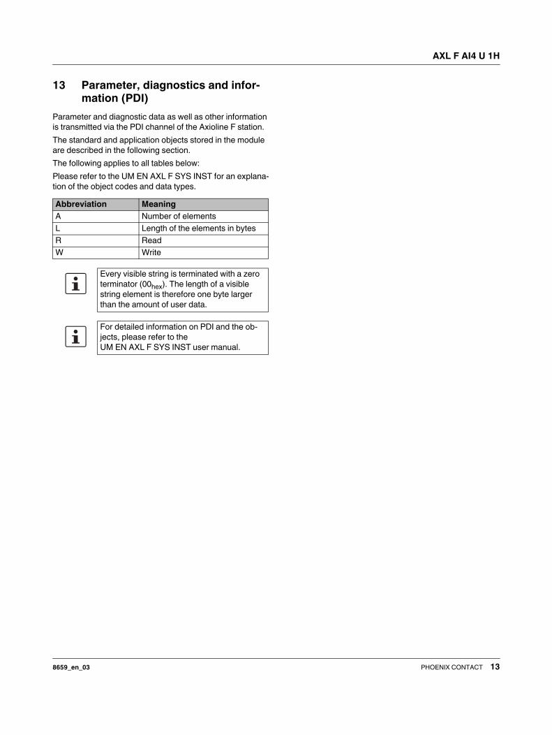
13 Parameter, diagnostics and infor-
mation (PDI)
Parameter and diagnostic data as well as other information
is transmitted via the PDI channel of the Axioline F station.
The standard and application objects stored in the module
are described in the following section.
The following applies to all tables below:
Please refer to the UM EN AXL F SYS INST for an explana-
tion of the object codes and data types.
Abbreviation Meaning
A Number of elements
L Length of the elements in bytes
R Read
W Write
Every visible string is terminated with a zero
terminator (00hex). The length of a visible
string element is therefore one byte larger
than the amount of user data.
For detailed information on PDI and the ob-
jects, please refer to the
UM EN AXL F SYS INST user manual.

AXL F AI4 U 1H
8659_en_03 PHOENIX CONTACT 14
14 Standard objects
14.1 Objects for identification (device rating plate)
Index
(hex)
Object name Object
type
Data type A L Rights Meaning Contents
Manufacturer
0001 VendorName Var Visible String 1 16 R Vendor name Phoenix Contact
0002 VendorID Var Visible String 1 7 R Vendor ID 00A045
0003 VendorText Var Visible String 1 49 R Vendor text Components and
systems for indus-
trial automation
0012 VendorURL Var Visible String 1 30 R Vendor URL http://www.phoenix-
contact.com
Module - general
0004 DeviceFamily Var Visible String 1 14 R Device family I/O analog IN
0006 ProductFamily Var Visible String 1 6 R Product family AXL F
000E CommProfile Var Visible String 1 4 R Communication pro-
file
633
000F DeviceProfile Var Visible String 1 5 R Device profile 0010
0011 ProfileVersion Record Visible String 2 11; 20 R Profile version 2011-12-07;
Basis - Profil V2.0
003A VersionCount Array Unsigned 16 4 4 * 2 R Version counter e. g., 0007 0001
0001 0001hex
Module - special
0005 Capabilities Array Visible String 1 8 R Features Energ_0
0007 ProductName Var Visible String 1 15 R Product name AXL F AI4 U 1H
0008 SerialNo Var Visible String 1 11 R Serial number xxxxxxxxxx (e. g.,
1234512345)
0009 ProductText Var Visible String 1 24 R Product text 4 analog input chan-
nels
000A OrderNumber Var Visible String 1 8 R Order No. 2688501
000B HardwareVersion Record Visible String 2 11; 3 R Hardware version e. g., 2010-06-21; 01
000C FirmwareVersion Record Visible String 2 11; 6 R Firmware version e. g., 2010-06-21;
V1.10
000D PChVersion Record Visible String 2 11; 6 R Parameter channel
version
2010-01-08; V1.00
0037 DeviceType Var Octet string 1 8 R Module identification 00 20 00 08 00 00 00
A5hex
Use of the device
0014 Location Var Visible String 1 59 R/W Location Can be filled out by
the user.
0015 EquipmentIdent Var Visible String 1 59 R/W Equipment identifier Can be filled out by
the user.
0016 ApplDeviceAddr Var Unsigned 16 1 2 R/W Application device
address
Can be filled out by
the user.
AXL F AI4 U 1H
8659_en_03 PHOENIX CONTACT 15
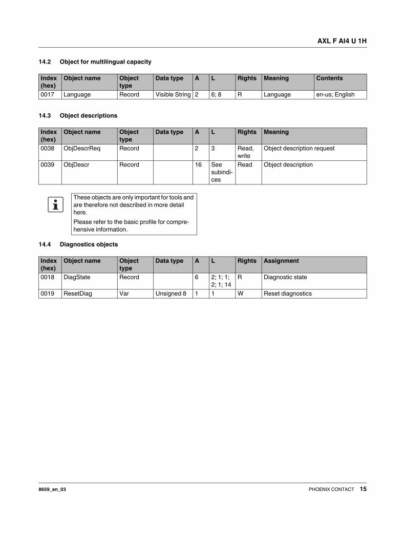
14.2 Object for multilingual capacity
14.3 Object descriptions
14.4 Diagnostics objects
Index
(hex)
Object name Object
type
Data type A L Rights Meaning Contents
0017 Language Record Visible String 2 6; 8 R Language en-us; English
Index
(hex)
Object name Object
type
Data type A L Rights Meaning
0038 ObjDescrReq Record 2 3 Read,
write
Object description request
0039 ObjDescr Record 16 See
subindi-
ces
Read Object description
These objects are only important for tools and
are therefore not described in more detail
here.
Please refer to the basic profile for compre-
hensive information.
Index
(hex)
Object name Object
type
Data type A L Rights Assignment
0018 DiagState Record 6 2; 1; 1;
2; 1; 14
R Diagnostic state
0019 ResetDiag Var Unsigned 8 1 1 W Reset diagnostics
AXL F AI4 U 1H
8659_en_03 PHOENIX CONTACT 16
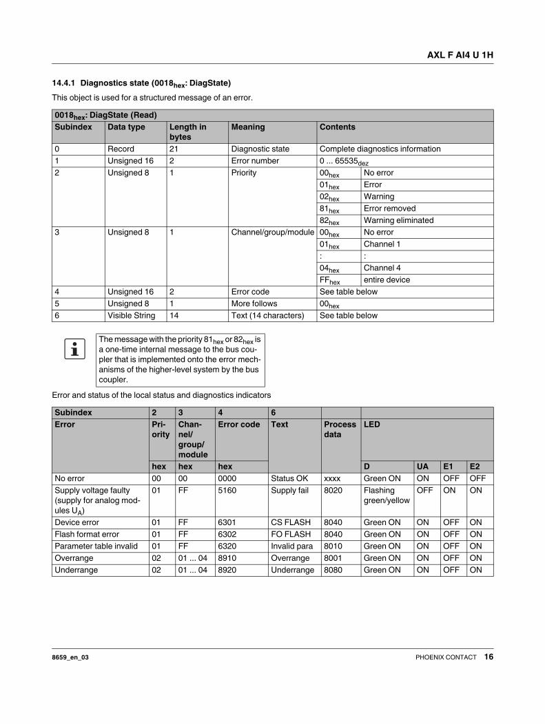
14.4.1 Diagnostics state (0018hex: DiagState)
This object is used for a structured message of an error.
Error and status of the local status and diagnostics indicators
0018hex: DiagState (Read)
Subindex Data type Length in
bytes
Meaning Contents
0 Record 21 Diagnostic state Complete diagnostics information
1 Unsigned 16 2 Error number 0 ... 65535dez
2 Unsigned 8 1 Priority 00hex No error
01hex Error
02hex Warning
81hex Error removed
82hex Warning eliminated
3 Unsigned 8 1 Channel/group/module 00hex No error
01hex Channel 1
: :
04hex Channel 4
FFhex entire device
4 Unsigned 16 2 Error code See table below
5 Unsigned 8 1 More follows 00hex
6 Visible String 14 Text (14 characters) See table below
The message with the priority 81hex or 82hex is
a one-time internal message to the bus cou-
pler that is implemented onto the error mech-
anisms of the higher-level system by the bus
coupler.
Subindex 2 3 4 6
Error Pri-
ority
Chan-
nel/
group/
module
Error code Text Process
data
LED
hex hex hex D UA E1 E2
No error 00 00 0000 Status OK xxxx Green ON ON OFF OFF
Supply voltage faulty
(supply for analog mod-
ules UA)
01 FF 5160 Supply fail 8020 Flashing
green/yellow
OFF ON ON
Device error 01 FF 6301 CS FLASH 8040 Green ON ON OFF ON
Flash format error 01 FF 6302 FO FLASH 8040 Green ON ON OFF ON
Parameter table invalid 01 FF 6320 Invalid para 8010 Green ON ON OFF ON
Overrange 02 01 ... 04 8910 Overrange 8001 Green ON ON OFF ON
Underrange 02 01 ... 04 8920 Underrange 8080 Green ON ON OFF ON

AXL F AI4 U 1H
8659_en_03 PHOENIX CONTACT 17
14.4.2 Reset diagnostic mesages (0019hex: ResetDiag)
You can delete the diagnostics memory and acknowledge the diagnostic messages with this object.
14.5 Objects for process data management
IN process data (0025hex: PDIN)
You can read the IN process data of the module with this object.
The structure corresponds to the representation in the "Process data" section.
0019hex: ResetDiag (Write)
Subindex Data type Length in
bytes
Meaning Contents
0 Unsigned 8 1 Reset diagnostics 00hex All diagnostic messages approved
02hex Deletes and acknowledges all
pending diagnostic messages that
have not been read out
06hex Deletes and acknowledges all the
diagnostic messages and allows no
further diagnostic messages
Other Reserved
Index
(hex)
Object name Object
type
Data type A L Rights Assignment
0025 PDIN Var Octet string 1 8 R Input process data
0026 PDOUT Var Octet string 1 8 R OUT process data; not applicable
003B PDIN_Descr Record 3 12 R Description of the IN process data
003C PDOUT_Descr Record 3 12 R Description of the output process data
Objects 003Bhex and 003Chex are only appli-
cable to tools and are therefore not described
in more detail here.
Please refer to the basic profile for compre-
hensive information.
0025hex: PDIN (Read)
Subindex Data type Length in bytes Meaning
0 Octet string 8 Input process data

AXL F AI4 U 1H
8659_en_03 PHOENIX CONTACT 18
14.6 Objects for device management
These objects are available as of firmware 1.10.
14.6.1 Reset parameterization (002Dhex: ResetParam)
This object is used to reset the module to the default set-
tings.
To reset the module value 01hex must be transferred during
write access. Any other values are not permissible and will
be acknowledged with an error.
Then the default settings of the channels are loaded and all
the user-set parameters are reset.
14.6.2 Checksum (002Ehex: Checksum)
The data of the startup objects is verified with this CRC32
checksum.
Index
(hex)
Object name Object
type
Data type A L Rights Meaning
002D ResetParam Simple
variable
Unsigned 8 1 1 R/W Reset parameterization
002E CheckSum Simple
variable
Unsigned 32 1 4 R Checksum
Checksum for the default setting: 9C 09 21 54hex

AXL F AI4 U 1H
8659_en_03 PHOENIX CONTACT 19
15 Application objects
15.1 Parameter table (0080hex: ParaTable)
Parameterize the module using this object.
In the case of valid parameters, the parameterization is stored in the module permanently.
After resetting, the module works with the last permanently stored data. Upon delivery, the module works with the default data
(default settings).
Parameterization channel 1 ... channel 4
Parameterization word
Data format
Index
(hex)
Object name Object
type
Data type A L Rights Assignment
0080 ParaTable Array Unsigned 16 6 6 * 2 R/W Parameter table
0082 Measured Value
Float
Array Octet string 4 4 * 6 R Measured values in the extended float
format
0083 PD Min Array Integer 16 4 4 * 2 R Minimum process data value
0084 PD Max Array Integer 16 4 4 * 2 R Maximum process data value
0080hex: ParaTable (read, write)
Subindex Data type Length in
bytes
Meaning Default value
0 Array of Unsigned 16 6 * 2 Read/write all elements See subindices
1 Unsigned 16 2 Parameterization of channel 1 0000hex
: Unsigned 16 2 : 0000hex
4 Unsigned 16 2 Parameterization of channel 4 0000hex
5 Unsigned 16 2 Data format 0000hex
6 Unsigned 16 2 Reserved 0000hex
15 14 13 12 11 10 9 8 7 6 5 4 3 2 1 0
0 0 0 Fil-
ter
0 0 Mean-
value
0 0 0 0 Measur-
ing range
Filter Code (bin) Code (hex)
30 Hz (default) 0 0
12 kHz 1 1
Measuring range Code (bin) Code (hex)
0 V ... 10 V (default) 0000 0
±10 V 0001 1
0 V ... 5 V 0010 2
±5 V 0011 3
Channel inactive 1111 F
Reserved Other
Mean-value Code (bin) Code (hex)
16-sample (default) 00 0
No mean-value 01 1
4-sample 10 2
32-sample 11 3
15 14 13 12 11 10 9 8 7 6 5 4 3 2 1 0
0 0 0 0 0 0 Data for-
mat
0 0 0 0 0 0 0 0
Data format Code (bin) Code (hex)
IB IL (default setting) 00 0
Reserved 01 1
S7-compatible 10 2
Reserved 11 3

AXL F AI4 U 1H
8659_en_03 PHOENIX CONTACT 20
15.2 Measured value in extended float format
(0082hex: Measured Value Float)
You can read the IN process data in IB IL or S7-compatible
format with the 0025hex object.
The 0082hex object is also available.
This object provides the measured value in the highest inter-
nal accuracy of the terminal in the float format.
Measured value channel 1 ... channel 4
Structure of the float format according to IEEE 754 in the bit
representation:
Some example values for conversion from floating point to
hexadecimal representation:
Extended Float Format
Extended Float Format is a specially defined format. It con-
sists of the measured value in float format, a status, and a
unit.
Status is necessary because the float format defines no pat-
terns providing information on the status of the numerical
value.
The status corresponds to the LSB of the diagnostic code in
IB IL format (e.g., overrange: status = 01, diagnostic code =
8001hex). If status = 0, the measured value is valid.
0082hex: Measured Value Float (Read)
Subindex Data type Length in
bytes
Meaning
0 Array of Re-
cords
4 * 6 Read all ele-
ments
1 Record 6 Measured value
for channel 1
: : : :
4 Record 6 Measured value
channel 4
Element Data type Length in
bytes
Meaning
1 Float 32 4 Measured value
in float format
according to
IEEE 754
2 Unsigned 8 1 Status
3 Unsigned 8 1 Unit
VEEE EEEE EMMM
MMMM
MMMM
MMMM
MMMM
MMMM
V 1 sign bit, 0: positive, 1: negative
E 8 bits exponent with offset 7Fhex
M 23 bits mantissa
Floating point Hexadecimal representa-
tion
1.0 3F 80 00 00
10.0 41 20 00 00
1.03965528 3F 85 13 6D
- 1.0 BF 80 00 00
Unit Code
Volt (V) 58 (3Ahex)
Status Code
Measured value is valid 00hex
Measured value is invalid Other

AXL F AI4 U 1H
8659_en_03 21PHOENIX CONTACT GmbH & Co. KG • 32823 Blomberg • Germany
phoenixcontact.com
15.3 Minimum process data value
(0083hex: PD Min)
Object 0083hex can be used to read the minimum IN process
data values.
The values are initialized after each parameterization. The
highest value is assigned for the minimum process data
value.
PD Min = 7FFF 7FFF 7FFF 7FFFhex
On every analog conversion, the PD Min value is compared
with the current measured values and overwritten if neces-
sary.
15.4 Maximum process data value
(0084hex: PD Max)
Object 0084hex can be used to read the maximum IN pro-
cess data values.
The values are initialized after each parameterization. The
lowest value is assigned for the maximum process data
value.
PD Max = 8000 8000 8000 8000hex
On every analog conversion, the PD Max value is compared
with the current measured values and overwritten if neces-
sary.
16 Device descriptions
The device is described in the device description files.
The device descriptions for controllers from Phoenix Con-
tact are included in PC Worx and the corresponding service
packs.
The device description files for other systems are available
for download at phoenixcontact.net/products in the down-
load area of the bus coupler used.
0083hex: PD Min (Read)
Subindex Data type Length in
bytes
Meaning
0 Array of Inte-
ger 16
4 * 2 Read all ele-
ments
1 Integer 16 2 Minimum pro-
cess data value
channel 1
: : : :
4 Integer 16 2 Minimum pro-
cess data value
channel 4
0084hex: PD Max (Read)
Subindex Data type Length in
bytes
Meaning
0 Array of Inte-
ger 16
4 * 2 Read all ele-
ments
1 Integer 16 2 Maximum pro-
cess data value
channel 1
: : : :
4 Integer 16 2 Maximum pro-
cess data value
channel 4