axobits - mdc.custhelp.com
TRANSCRIPT

Dr. Alison MurrayDesert Research InstituteUniversity of Nevada, Reno
As functional genomics moves from modelorganisms to non-model organisms andcommunities of organisms, new challengesarise for researchers and their instruments.
Recently, an interdisciplinary research team,headed by microbial ecologist, Dr. CraigCary, University of Delaware, embarked ona 3½ week research cruise aboard the RVAtlantis to the East Pacific Rise, 100 milesoff Costa Rica. Our mission, ‘Extreme 2003,Depths of Discovery,’ brought togetherseveral research groups including those ledby Dr. Eric Johnson of the University ofOregon, and myself, Dr. Alison Murray ofthe Desert Research Institute in Reno, NV.
The object of our mission was to delve intoenvironmental functional genomics bydetecting gene expression in biologicalsamples collected at deep-seahydrothermal vents over a mile beneaththe surface. At these sites, temperaturesfluctuate from four to over three hundreddegrees Celsius rapidly throughout the day,and vent fluids are laden with heavy metals(e.g. iron, manganese, and arsenic) andhigh concentrations of sulfide. Despitethese extremes, Alvinella pompejana (thePompeii worm) and affiliated bacterialepisymbionts—a consortia ofpredominately Epsilon proteobacteria—notonly tolerate the conditions, but flourish onthe vent chimneys. Little is knownregarding the specific details of thesymbiotic relationship between the wormand its symbionts, how the worm
withstands the toxic environment, or howthe symbionts make their living. We hopethat gene expression surveys will help tounravel the story of thermal adaptation,tolerance, and function, as well as themetabolic potential for these organisms.
Thus, our mission had three primaryobjectives; sample collection, mRNAprocessing, and testing the GenePix 4000Bscanner at sea. On a number of Alvin (thesubmersible) dives, we collected the wormsin custom designed chambers that weimmediately flooded at depth withRNAlater (Ambion, Inc.). This was only thebeginning of tricky science. Processing theorganisms to ensure the highest qualitymRNA is a technical feat, not to mentionthe rest of the tasks involved in extracting,labeling, and performing the hybridizationsthemselves. (cont.)
Integrated Solutions for Cellular Neuroscience, Cell-BBased Screening and Microarray Analysis Vol. 41 July 2004
TThhee ccrreeww wwiitthh AAllvviinn aanndd GGeenneePPiixx 44000000BB..
AAxxooBBiittssGGeenneePPiixx 44000000BB GGeettss iittss SSeeaa LLeeggss
IInn TThhiiss IIssssuuee
PPrroodduucctt NNeewwss 22SSppeecciiaall PPrriicciinngg ffoorr PPaattcchhXXpprreessssMMuullttiiCCllaammpp 33rrdd PPaarrttyy CCoonnttrroollGGeenneePPiixx 44220000 AAuuttoollooaaddeerrGGeenneePPiixx PPrroo 66AAccuuiittyy 44PPaattcchhXXpprreessss hhEERRGG NNeewwss
FFooccuuss oonn MMeetthhooddss 44TThhee MMiigghhttyy MMooddeell CCeellllAA GGlliimmppssee aatt BBrreeaasstt CCaanncceerr CCaarrbboonn--FFiibbeerr MMiiccrrooeelleeccttrrooddeess
TTooooll TTiippss 66DDaattaaXXpprreessss EECC5500 SSccrriipptt
QQ&&AA 77ppCCLLAAMMPP 99 MMeemmbbrraannee TTeesstt
TThhee AAxxooppoorraattoorr 880000AA,,ssiinnggllee--cceellll eelleeccttrrooppoorraattoorr,,
iiss nnooww sshhiippppiinngg!!wwwwww..aaxxooppoorraattoorr..ccoomm

cont. from Page 1...
Ships are challenging platforms to conducteven the simplest of maneuvers requiredby a land-lubbing functional genomicist.Imagine trying to pipette 30 µl of a Cy-dyelabeled nucleic acid onto a 1x1 cm coverslip in 10 ft seas in the dark! No less difficultwas the development of custom DNAmicroarrays to study gene expression.Amidst ship motions and vibrations, saltysea air, and the occasional high seas theGenePix 4000B worked perfectly, survivingall these rigors for the entire voyage.
Future experiments at sea will afford us theopportunity to move from samplecollection to detection of gene expressionin as few as two days. This should allow usto learn rapidly from our collection efforts,and modify our sampling strategies whenneeded. We plan to take a GenePix 4000Bon our next cruise, and hope to test geneexpression in the Pompeii worm, as well asan environmental microbial genome arrayto test hypotheses related to the metabolicpathways utilized by the worm’scommunity of episymbiotic bacteria.For more information, visitwww.ocean.udel.edu/extreme2003/home.html
AAnn EEddiittoorr’’ss RReefflleeccttiioonnssAlthough the AxoBits newsletter mayundergo a few changes following themerger of Axon and Molecular Devices, itsfocus−pointing the way to improvedmethods and to new avenues of discovery−will likely remain the same. We lookforward to the opportunity to draw from aneven larger pool of contributors, who likethose of the past will provide high-calibercontent in the form of application notes,focus on methods and technical tips.
Still there is a twinge of nostalgia on thepart of the current editor. I was fortunate toinherit such a plum posting. Everyone whocontributed to the newsletter made my joba labor of love. I am especially indebted tothe prolific duo of Drs. Jim Rae and RickLevis. Over the years they tackled a rangeof patch pipette-related topics including:perforated-patch recording, methods foroptimizing a system for ultra-low noiserecordings and, most recently, single-cellelectroporation. Apparently they draw froman inexhaustible well of innovation and, inmy mind are true patch-pipette populists.
All the best,
Al Walter, Ph.D.
SSppeecciiaall AAccaaddeemmiicc PPrriicciinnggffoorr tthhee PPaattcchhXXpprreessss 77000000AA!!By now most of you have heard of therevolutionary PatchXpress, AutomatedParallel Patch-Clamp system. ThePatchXpress is a 16-channel planar patchclamp for increasing ion channel researchthroughput. Academics can now enjoy aspecial price to help them get this cutting-edge technology in their labs or shared-usefacility.
For a quote, please contact Anna Hastings,at 510-675-6200 or [email protected].
For more information, visitwww.patchxpress.com
2 · AxoBits 41 · www.axon.com
A MESSAGE FROM......
EEddiittoorr--iinn--CChhiieeffAl Walter, Ph.D.
EEddiittoorr aanndd PPrroodduuccttiioonnSimone Elletson
MMaarrkkeettiinngg aannddPPuubblliicc RReellaattiioonnssSimone ElletsonDebbie Quinn
CCoonnttrriibbuuttoorrssJennifer DentToni Figl, Ph.D.Alan Finkel, Ph.D.Dave GallegosMichael L. Heien, Ph.D.Wilson LewAlison Murray, Ph.D.Siobhan PickettJames Rountree, Ph.D.Damian Verdnik, Ph.D.R. Mark Wightman, Ph.D.Ward Yuhas, Ph.D.
MMuullttiiCCllaammpp 33rrdd PPaarrttyyCCoonnttrrooll NNooww AAvvaaiillaabblleeThe MultiClamp 700A and 700B amplifiersare each controlled by a software interface(‘MultiClamp 700x Commander’). Althoughthis control interface is required to run theamplifier, you can now develop your ownapplication to control MultiClamp 700xCommander via a dynamic link library(DLL). We hope this will allow those of youwith special needs and skills to use theMultiClamp 700x in custom applications.
The DLL code and documentation isavailable in MultiClamp 700A Commanderversion 1.3 and 700B Commander version2.1 (Windows versions only). These latestversions are available on the MultiClampUpdates page (see ‘Downloads’ atwww.axon.com).
AAllaann FFiinnkkeell,, FFoouunnddeerr aanndd CCEEOO,, AAxxoonn IInnssttrruummeennttss
This will be the last issue of AxoBits to bepublished under the Axon banner. We aregoing through a rite of passage, beingacquired by Molecular Devices Corporationand metamorphosing into a stronger,combined company. Although our namewill change and we will be merged into abigger entity, it is my sincere hope andindeed my intention that our efforts toserve you will continue and that thewonderful relationship that we haveenjoyed with you for twenty-one years willbe preserved.
I will be joining Molecular Devices as ChiefTechnology Officer. Like a teenager leaving
home to go to college, I am a little scaredbut full of eager anticipation. My job willpartly be a continuation of the traditionalAxon after-sales service; that is, to ensurethat the combined company efficientlyreaps maximum value from its purchase, byassimilating and building on the best of theAxon traditions. My other contribution willbe to the new product development effortrequired to maintain the company as aprovider of leading edge, innovativeproducts.
While waiting for regulatory andshareholder approval, we are continuing tomake and support our products, we aredeveloping exciting next generationproducts in neurosciences, microarrayanalysis and cell based screening, and weare continuing to work with you, ourcustomers, to answer questions, solve
problems and generally respond as quicklyas always.
In many respects it is business as usual atAxon, but like me, all of Axon’s employeesare feeling a mixture of sweet nostalgiamixed with new hopes and expectations.This will be my last message to you as CEOof Axon Instruments, and in that capacity itis my pleasure to thank you for your loyaltyand to state my strong hope that I willcontinue to hear from you, or of you, as ahappy Molecular Devices customer.
Best wishes to you all,
Alan Finkel, Ph.D.CEO, Axon Instruments
James Rae in his element.
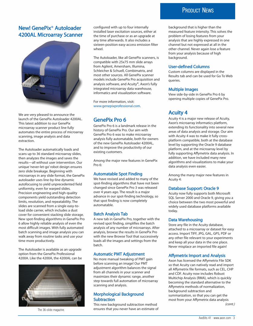
NNeeww!! GGeenneePPiixx® AAuuttoollooaaddeerr44220000AALL MMiiccrrooaarrrraayy SSccaannnneerr
We are very pleased to announce thelaunch of the GenePix Autoloader 4200AL.This latest addition to our GenePixmicroarray scanner product line fullyautomates the entire process of microarrayscanning, image analysis and dataextraction.
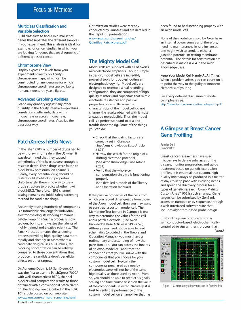
The Autoloader automatically loads andscans up to 36 standard microarray slides,then analyzes the images and saves theresults—all without user intervention. Ourunique ‘never-let-go’ robot design ensureszero slide breakage. Beginning withmicroarrays in any slide format, the GenePixautoloader uses line-by-line dynamicautofocusing to yield unprecedented fielduniformity, even for warped slides.Precision engineering and high-qualitycomponents yield outstanding detectionlimits, resolution, and repeatability. Theslides are scanned from a single easy-to-load slide carrier, which includes a dustcover for convenient stacking slide storage. New spot-finding algorithms in GenePix Pro6 allow highly reliable analysis of even themost difficult images. With fully automatedbatch scanning and image analysis you canwalk away from routine tasks and use yourtime more productively.
The Autoloader is available as an upgradeoption from the GenePix Professional4200A. Like the 4200A, the 4200AL can be
configured with up to four internallyinstalled laser excitation sources, either atthe time of purchase or as an upgrade atany time afterwards. It also includes asixteen-position easy-access emission filterwheel.
The Autoloader, like all GenePix scanners, iscompatible with 25x75 mm slide arraysfrom Agilent, Amersham, Illumina,Schleicher & Schuell, Combimatrix, andmost other sources. All GenePix scannermodels include GenePix Pro acquisition andanalysis software, and Acuity®, Axon’s fullyintegrated microarray data warehouse,informatics and visualization software.
For more information, visit:www.genepixprofessional.com.
GGeenneePPiixx PPrroo 66GenePix Pro 6 is a landmark release in thehistory of GenePix Pro. Our aim withGenePix Pro 6 was to make microarrayanalysis fully automatable, both for ownersof the new GenePix Autoloader 4200AL,and to improve the productivity of ourexisting customers.
Among the major new features in GenePixPro 6:
AAuuttoommaattaabbllee SSppoott FFiinnddiinnggWe have revised and added to many of thespot-finding algorithms that have not beenchanged since GenePix Pro 3 was releasedover 4 years ago. The result is a majoradvance in our spot-finding technology, sothat spot finding is now completelyautomatable.
BBaattcchh AAnnaallyyssiiss TTaabbA new tab in GenePix Pro, together with therevised spot finding, simplifies the batchanalysis of any number of microarrays. Afteranalysis, browse the results in GenePix Prowith the new Browse Tool that successivelyloads all the images and settings from thebatch.
AAuuttoommaattiicc PPMMTT AAddjjuussttmmeennttNo more manual tweaking of PMT gainbefore scanning an image! Our PMTadjustment algorithm balances the signalfrom all channels in your scanner andmaximizes their dynamic range, anotherstep towards full automation of microarrayscanning and analysis.
MMoorrpphhoollooggiiccaall BBaacckkggrroouunnddSSuubbttrraaccttiioonnThis new background subtraction methodensures that you never have an estimate of
background that is higher than themeasured feature intensity. This solves theproblem of losing features from youranalysis that are highly expressed in onechannel but not expressed at all in theother channel. Never again lose a featurefrom your analysis because of highbackground.
UUsseerr--ddeeffiinneedd CCoolluummnnssCustom columns are displayed in theResults tab and can be used for Go To Webqueries.
MMuullttiippllee IImmaaggeessView side-by-side in GenePix Pro 6 byopening multiple copies of GenePix Pro.
AAccuuiittyy 44Acuity 4 is a major new release of Acuity,Axon’s microarray informatics platform,extending its functionality into several newareas of data analysis and storage. Our aimwith Acuity 4 was to make it fully cross-platform compatible, both at the databaselevel by supporting the Oracle 9 databaseplatform, and at the microarray level byfully supporting Affymetrix data analysis. Inaddition, we have included many newalgorithms and visualizations to make yourdata analysis even easier.
Among the many major new features inAcuity 4:
DDaattaabbaassee SSuuppppoorrtt:: OOrraaccllee 99Acuity now fully supports both MicrosoftSQL Server 2000 and Oracle 9, giving you achoice between the two most powerful andwidely used database platforms availabletoday.
DDaattaa WWaarreehhoouussiinnggStore any file in the Acuity database,attached to a microarray or dataset for easyaccess. Import TIFF, JPG, GAL, GPS, PDF orany other file relevant to your experimentsand keep all your data in the one place.Never misplace an imported file again!
AAffffyymmeettrriixx IImmppoorrtt aanndd AAnnaallyyssiiss Axon has licensed the Affymetrix File SDKso that Acuity can natively read and importall Affymetrix file formats, such as CEL, CHPand CDF. Acuity now includes RobustMultichip Analysis (RMA), which is quicklybecoming the standard alternative to theAffymetrix methods of normalization,background subtraction andsummarization, so that you can get themost from your Affymetrix data analysis
(cont.)
AxoBits 41 · www.axon.com · 3
PRODUCT NEWS
The 36-slide magazine.
MMuullttiiccllaassss CCllaassssiiffiiccaattiioonn aannddVVaarriiaabbllee SSeelleeccttiioonnBuild classifiers to find a minimal set ofgenes that separates the different samplesin your experiment. This analysis is ideal, forexample, for cancer studies; in which youare looking for genes that are diagnostic ofdifferent types of cancer.
CChhrroommoossoommee VViieewwDisplay expression levels from yourexperiments directly on Acuity’schromosome maps, which can beconstructed for any genome for whichchromosome coordinates are available:human, mouse, rat, yeast, fly, etc.
AAddvvaanncceedd GGrraapphhiinngg AAbbiilliittiieessGraph any quantity against any otherquantity in the Acuity interface—p-values,correlation coefficients, data withinmicroarrays or across microarrays,chromosome coordinates. Visualize thedata your way.
PPaattcchhXXpprreessss hhEERRGG NNeewwssIn the late 1990’s, a number of drugs had tobe withdrawn from sale in the US when itwas determined that they causedarrhythmias of the heart severe enough toresult in death. These drugs were found toblock hERG potassium ion channels .Clearly, every potential drug should betested for hERG-blocking properties.Unfortunately, there is no way to use adrug’s structure to predict whether it willblock hERG. Therefore, hERG channeltesting remains the initial safety screeningmethod for candidate drugs.
Accurately testing hundreds of compoundsis a formidable challenge for individualelectrophysiologists working at manualpatch-clamp rigs. Such a process is slow,tedious, boring, and wastes the talents ofhighly trained and creative scientists. ThePatchXpress automates the screeningprocess providing high-quality data morerapidly and cheaply. In cases where acandidate drug causes hERG block, theblocking concentration can be reliablycompared to those concentrations thatproduce the candidate drug’s beneficialeffects on other targets.
Dr. Adrienne Dubin (J&J, San Diego, CA)was the first to use the PatchXpress 7000Awith well-characterized hERG channelblockers and compare the results to thoseobtained with a conventional patch clamprig. Her findings are described in the hERG101 article posted on our web site:www.axon.com/cs_herg_screening.html.
Optimization studies were recentlyconducted by Quintiles and are detailed inthe Rapid ICE presentation:www.axon.com/screeningnotes/Quintiles_PatchXpress.pdf.
TThhee MMiigghhttyy MMooddeell CCeellllModel cells are supplied with all of Axon’smicroelectrode amplifiers. Though simplein design, model cells are incrediblypowerful tools for troubleshooting anelectrophysiology rig. Model cells aredesigned to resemble a real recordingconfiguration; they are composed of highquality resistors and capacitors that mimicelectrode resistances and passiveproperties of cells. Because thecharacteristics of the model cell do notchange, the results obtained with it mustalways be reproducible. Thus, the modelcell is a perfect standard to test andtroubleshoot the rig. Some of the thingsyou can do:
• Check that the scaling factors arecorrectly set in Clampex(See Axon Knowledge Base Article # 871)
• Narrow the search for the origin of adrifting electrode potential (See Axon Knowledge Base Article # 281)
• Verify that the whole-cell compensation circuitry is functioningproperly (See detailed tutorials of the Theory and Operation manuals)
If the passive properties of the cells fromwhich you record differ greatly from thoseof the Axon model cell, then you may wantto construct a custom model cell. TheMembrane Test feature in Clampex is oneway to determine the values for the celland a patch electrode. (See AxonKnowledge Base Articles # 649 – 652.)Although you need not be able to readschematics (provided in the Theory andOperation Manuals), you must have arudimentary understanding of how theparts function. You can access the innardsof an Axon model cell and trace theconnections that you will make with thecomponents that you choose for yourcustom model cell. Typically thecomponents purchased at a nearbyelectronics store will not be of the samehigh quality as those used by Axon. Evenso, you should be able to predict a signal’sscaling and time course based on the valueof the components selected. Naturally, it isbest to verify the performance of thecustom model cell on an amplifier that has
been found to be functioning properly withan Axon model cell.
None of the model cells sold by Axon havean internal power source and, therefore,need no maintenance. In rare instancesone might wish to emulate either ajunction potential or resting membranepotential. The details for construction aredescribed in Article # 784 in the AxonKnowledge Base.
KKeeeepp YYoouurr MMooddeell CCeellll HHaannddyy AAtt AAllll TTiimmeess!!When a problem arises, you can count on itto point the way to the guilty or innocentelement(s) of your rig.
For a very detailed discussion of modelcells, please see:http://fisio.dipbsf.uninsubria.it/scuola/patch.pdf
AA GGlliimmppssee aatt BBrreeaasstt CCaanncceerrGGeennee PPrrooffiilliinngg
Jennifer DentCombimatrix
Breast cancer researchers have usedmicroarrays to define subclasses of thedisease, monitor progression, and guidetreatment based on genetic expressionprofiles. It is essential that custom, high-quality microarrays be produced in a matterof days to keep pace with evolving needsand speed the discovery process for alltypes of genetic research. CombiMatrix’sCustomArray™ 902 is such an array. Genetargets can be submitted by GenBankaccession number, or by sequence, througha web-interfaced software suite thatincludes algorithm-based probe design.
CustomArrays are produced using asemiconductor-based, electrochemically-controlled in situ synthesis process that
(cont.)
4 · AxoBits 41 · www.axon.com
FOCUS ON METHODS
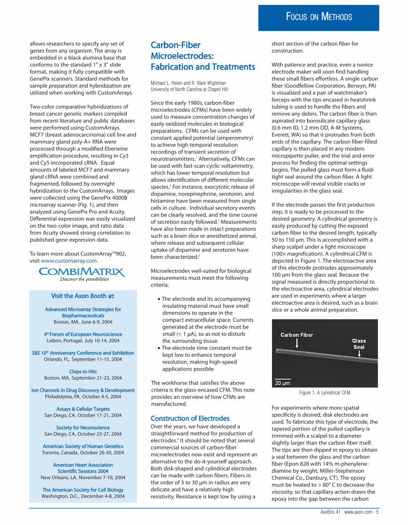
Figure 1. Custom array slide visualized in GenePix Pro
AxoBits 41 · www.axon.com · 5
FOCUS ON METHODS
allows researchers to specify any set ofgenes from any organism. The array isembedded in a black alumina base thatconforms to the standard 1" x 3" slideformat, making it fully compatible withGenePix scanners. Standard methods forsample preparation and hybridization areutilized when working with CustomArrays.
Two-color comparative hybridizations ofbreast cancer genetic markers compiledfrom recent literature and public databaseswere performed using CustomArrays.MCF7 (breast adenocarcinoma) cell line andmammary gland poly-A+ RNA wereprocessed through a modified Eberwineamplification procedure, resulting in Cy3and Cy5 incorporated cRNA. Equalamounts of labeled MCF7 and mammarygland cRNA were combined andfragmented, followed by overnighthybridization to the CustomArrays. Imageswere collected using the GenePix 4000Bmicroarray scanner (Fig. 1), and thenanalyzed using GenePix Pro and Acuity.Differential expression was easily visualizedon the two-color image, and ratio datafrom Acuity showed strong correlation topublished gene expression data.
To learn more about CustomArray™902,visit www.customarray.com.
CCaarrbboonn--FFiibbeerrMMiiccrrooeelleeccttrrooddeess::FFaabbrriiccaattiioonn aanndd TTrreeaattmmeennttss
Michael L. Heien and R. Mark WightmanUniversity of North Carolina at Chapel Hill
Since the early 1980s, carbon-fibermicroelectrodes (CFMs) have been widelyused to measure concentration changes ofeasily oxidized molecules in biologicalpreparations. CFMs can be used withconstant applied potential (amperometry)to achieve high temporal resolutionrecordings of transient secretion ofneurotransmitters.1 Alternatively, CFMs canbe used with fast-scan cyclic voltammetry,which has lower temporal resolution butallows identification of different molecularspecies.1 For instance, exocytotic release ofdopamine, norepinephrine, serotonin, andhistamine have been measured from singlecells in culture. Individual secretory eventscan be clearly resolved, and the time courseof secretion easily followed.2 Measurementshave also been made in intact preparationssuch as a brain slice or anesthetized animal,where release and subsequent cellularuptake of dopamine and serotonin havebeen characterized.3
Microelectrodes well-suited for biologicalmeasurements must meet the followingcriteria:
• The electrode and its accompanyinginsulating material must have small dimensions to operate in the compact extracellular space. Currents generated at the electrode must be small (< 1 µA), so as not to disturb the surrounding tissue.
• The electrode time constant must be kept low to enhance temporal resolution, making high-speed applications possible.
The workhorse that satisfies the abovecriteria is the glass-encased CFM. This noteprovides an overview of how CFMs aremanufactured.
CCoonnssttrruuccttiioonn ooff EElleeccttrrooddeessOver the years, we have developed astraightforward method for production ofelectrodes.4 It should be noted that severalcommercial sources of carbon-fibermicroelectrodes now exist and represent analternative to the do-it-yourself approach.Both disk-shaped and cylindrical electrodescan be made with carbon fibers. Fibers inthe order of 3 to 30 µm in radius are verydelicate and have a relatively highresistivity. Resistance is kept low by using a
short section of the carbon fiber forconstruction.
With patience and practice, even a noviceelectrode maker will soon find handlingthese small fibers effortless. A single carbonfiber (Goodfellow Corporation, Berwyn, PA)is visualized and a pair of watchmaker’sforceps with the tips encased in heatshrinktubing is used to handle the fibers andremove any debris. The carbon fiber is thenaspirated into borosilicate capillary glass(0.6 mm ID, 1.2 mm OD, A-M Systems,Everett, WA) so that it protrudes from bothends of the capillary. The carbon fiber-filledcapillary is then placed in any modernmicropipette puller, and the trial and errorprocess for finding the optimal settingsbegins. The pulled glass must form a fluid-tight seal around the carbon fiber. A lightmicroscope will reveal visible cracks orirregularities in the glass seal.
If the electrode passes the first productionstep, it is ready to be processed to thedesired geometry. A cylindrical geometry iseasily produced by cutting the exposedcarbon fiber to the desired length, typically50 to 150 µm. This is accomplished with asharp scalpel under a light microscope(100× magnification). A cylindrical CFM isdepicted in Figure 1. The electroactive areaof this electrode protrudes approximately100 µm from the glass seal. Because thesignal measured is directly proportional tothe electroactive area, cylindrical electrodesare used in experiments where a largerelectroactive area is desired, such as a brainslice or a whole animal preparation.
For experiments where more spatialspecificity is desired, disk electrodes areused. To fabricate this type of electrode, thetapered portion of the pulled capillary istrimmed with a scalpel to a diameterslightly larger than the carbon fiber itself.The tips are then dipped in epoxy to obtaina seal between the glass and the carbonfiber (Epon 828 with 14% m-phenylene-diamine by weight, Miller-StephensonChemical Co., Danbury, CT). The epoxymust be heated to > 80° C to decrease theviscosity, so that capillary action draws theepoxy into the gap between the carbon
Figure 1. A cylindrical CFM.
VViissiitt tthhee AAxxoonn BBooootthh aatt::
AAddvvaanncceedd MMiiccrrooaarrrraayy SSttrraatteeggiieess ffoorrBBiioopphhaarrmmaacceeuuttiiccaallss
Boston, MA, June 6-9, 2004
44tthh FFoorruumm ooff EEuurrooppeeaann NNeeuurroosscciieenncceeLisbon, Portugal, July 10-14, 2004
SSBBSS 1100tthh AAnnnniivveerrssaarryy CCoonnffeerreennccee aanndd EExxhhiibbiittiioonnOrlando, FL, September 11-15, 2004
CChhiippss ttoo HHiittssBoston, MA, September 21-23, 2004
IIoonn CChhaannnneellss iinn DDrruugg DDiissccoovveerryy && DDeevveellooppmmeennttPhiladelphia, PA, October 4-5, 2004
AAssssaayyss && CCeelllluullaarr TTaarrggeettssSan Diego, CA, October 17-21, 2004
SSoocciieettyy ffoorr NNeeuurroosscciieenncceeSan Diego, CA, October 23-27, 2004
AAmmeerriiccaann SSoocciieettyy ooff HHuummaann GGeenneettiiccssToronto, Canada, October 26-30, 2004
AAmmeerriiccaann HHeeaarrtt AAssssoocciiaattiioonn SScciieennttiiffiicc SSeessssiioonnss 22000044
New Orleans, LA, November 7-10, 2004
TThhee AAmmeerriiccaann SSoocciieettyy ffoorr CCeellll BBiioollooggyyWashington, D.C., December 4-8, 2004

fiber and the glass. The epoxy is then cured(100 °C for 12 h, 150 °C for 2 days). The tipof the microelectrode is lowered onto abeveler (BV-10 Micropipette Beveler, SutterInstrument, Novato, CA) and polished at anangle to produce an oval cross section ofthe carbon fiber. A disk microelectrode canbe seen in Figure 2.
The electrode is backfilled with electrolyte(4 M potassium acetate, 150 mM potassiumchloride) and fitted with a wire thatconnects to the input of theelectrochemistry equipment. An electricalcontact can also be made by using colloidalgraphite, silver paint, or mercury.
EElleeccttrrooddee PPrreettrreeaattmmeennttssAlthough one can use freshlymanufactured electrodes, there are severalpretreatments that can dramatically alterthe surface properties of the carbon fiber.These will create CFMs that have their ownunique measurement characteristics.5 Themost common treatment is the use ofNafion®, a perfluorosulfonated ionexchange polymer, which acts to excludeanions from the electrode surface whileconcentrating cations.6 This enhancesselectivity, and protects the electrodesurface from fouling.
If a CFM is soaked for at least 10 min inisopropanol purified with Norit A activatedcarbon (ICN, Costa Mesa, CA), the sensitivitycan be improved by more than threefold.7
Presumably this cleans the surface andchanges the surface groups on theelectrode. This cleaning step is especiallyimportant in cases where themicroelectrode’s surface cannot bepolished due to geometry.
Many electrochemical treatments work toenhance the adsorption and electrontransfer kinetics of the electrode surface. Infact, it has been remarked that there are asmany electrochemical treatments as thereare labs using carbon electrodes. Most ofthese involve applying a positive potentialto the electrode to obtain the desiredresults.8-10 Such treatments dramatically
change the surface properties (asdemonstrated by scanning electronmicroscopy11) and increases surfaceoxides.12 This increases the sensitivity of theelectrode to analytes such as dopamine,but causes a slower electrode response.
CFM capacitance should be minimized tomake low-noise measurements. Thecapacitance has two components, thecapacitance across the glass and the largercontribution from the electrical doublelayer at the electrode tip. These twocomponents are kept to minimum in twoways:
• By producing a well-insulated electrode, solution cannot creep inbetween the carbon fiber and surrounding glass pipette.
• By keeping the electrode surface smooth.
In summary, CFMs are wonderful tools formeasuring concentration changes of a widevariety of easily oxidized biomolecules.These electrodes can be manufactured tomeet the constraints of space and responsebandwidth and their specificity can beoptimally tuned by using propermethodology combined with selectivewell-characterized treatments.
RReeffeerreenncceess
1. Cahill, P.S., Walker, Q.D., Finnegan, J.M., Mickelson, G.E.,Travis, E.R., Wightman, R.M. Microelectrodes for themeasurement of catecholamines in biological systems,Anal. Chem., 68:3180-3186, 1996.
2. Wightman, R.M., Jankowski, J.A., Kennedy, R.T., Kawagoe,K.T., Schroeder, T.J., Leszczyszyn, D.J., Near, J.A., Diliberto,E.J., Jr., Viveros, O.H. Temporally resolved catecholaminespikes correspond to single vesicle release from individualchromaffin cells, Proc. Natl. Acad. Sci. USA. 88:10754-10758, 1991.
3. Millar, J., Stamford, J.A., Kruk, Z.L., Wightman, R.M.Electrochemical, pharmacological andelectrophysiological evidence of rapid dopamine releaseand removal in the rat caudate nucleus following electricalstimulation of the median forebrain bundle, Eur. J.Pharmacol. 110099:341-348, 1985.
4. Kawagoe, K.T., Zimmerman, J.B., Wightman, R.M. Principlesof voltammetry and microelectrode surface states, J.Neurosci. Meth. 4488:225-240, 1993.
5. McCreery, R.L., Cline, K.K. Carbon Electrodes, LLaabboorraattoorryyTTeecchhnniiqquueess iinn EElleeccttrrooaannaallyyttiiccaall CChheemmiissttrryy,, 22nndd eedd.. P.T.Kissinger, W.R. Heineman. Eds. New York: Marcel Dekker,Inc, 1996.
6. Gerhardt, G.A., Oke, A.F., Nagy, G., Moghaddam, B., Adams,R.N. Nafion-coated electrodes with high selectivity for CNSelectrochemistry, Brain Research. 229900:390-395, 1984.
7. Bath, B.D., Michael, D.J., Trafton, B.J., Joseph, J.D., Runnels,P.L., Wightman, R. M. Subsecond adsorption anddesorption of dopamine at carbon-fiber microelectrodes,Anal. Chem. 7722:5994-6002, 2000.
8. Gonon, F., Buda, M., Cespuglio, R., Jouvet, M., Pujol, J.F. Invivo electrochemical detection of catechols in theneostriatum of anaesthetized rats: dopamine or DOPAC?,Nature. 228866:902-904, 1980.
9. Hafizi, S., Kruk, Z.L., Stamford, J.A. Fast cyclic voltammetry:improved sensitivity to dopamine with extendedoxidation scan limits, J. Neurosci. Meth. 3333:41-49, 1990.
10. Heien, M.L.A.V., Phillips, P.E.M., Stuber, G.D., Seipel, A.T.,Wightman, R.M. Overoxidation of carbon-fibermicroelectrodes enhances dopamine adsorption andincreases sensitivity, Analyst., 112288:1413-1419, 2003.
11. Swain, G.M., Kuwana, T. Electrochemical Formation of HighSurface-area Carbon-Fibers, Anal. Chem. 6633:517-519, 1991.
12. Alsmeyer, Y.W., McCreery, R.L. Surface Enhanced RamanExamination of Carbon Electrodes - Effects of LaserActivation and Eletrochemical Pretreatment, Langmuir.77:2370-2375, 1991.
DDaattaaXXpprreessss EECC5500 SSccrriippttThe ‘Voltage-Gated EC50 (no rundown)’script in DataXpress calculates dose-response relationships and effectiveconcentration (EC) values for sets of testcompounds. This article provides somebackground information to help set up thescript.
The script measures the peak current inevery sweep for each cell procedure in thedataset (a ‘cell procedure’ is the applicationof the defined experimental procedure toone cell). It plots the measurements foreach cell procedure against time (Figure 1).The measurements could come from onecontinuous recording run throughout theprocedure, or numbers of separaterecordings run sequentially—the scripttreats both scenarios the same. The relativeeffect of each dose is used to generate adose-response graph, which is fit with a Hillcurve. The Hill equation yields the effectiveconcentration for a particular percentage ofthe maximal effect—typically 50%, hence‘EC50’ in the script name.
A minimum of four points is required toapply the Hill fit to dose-response data.Two extra points, at the top and bottom ofthe data range, can be added in the script,so data with as few as two concentrationpoints can be fit. The script will also runwith data that have a different compoundadded after the test compound, forexample, a dose that completely blocks allchannel current. Such a ‘hammer dose’ isnot at this time used in the calculation ofcurrent inhibition, but this feature will beincorporated soon.
To prepare a dataset, view the trialsreturned from your original query andremove bad trials by selecting them in thetrial list and then hitting Control + Delete.Use the Trial Editor to remove anomaloussweeps and spikes.
When the trials are ready for analysis, setcursors 3 and 4 to the region of the sweepwhere you want to measure the peak, andcursors 1 and 2 to a baseline region (unlessyou intend to use the absolute peakmeasurements option in the script). Then
6 · AxoBits 41 · www.axon.com
TOOL TIP
Figure 1. Peak measurements over time for a single cell,showing compound additions. In this example 6 trials
were run, as evidenced by the gaps in the data.
Figure 2. A disk microelectrode.
go to the Script tab and open ‘Voltage-Gated EC50 (no rundown)’. By opening thescript after the trial has been opened in theTrials tab, the script’s ‘Use signal’ list boxautomatically shows the number of signalsthat the trial contains, starting with ‘0’.PatchXpress users who enabled P/N leaksubtraction will generally select the second,leak-corrected signal, ‘1’.
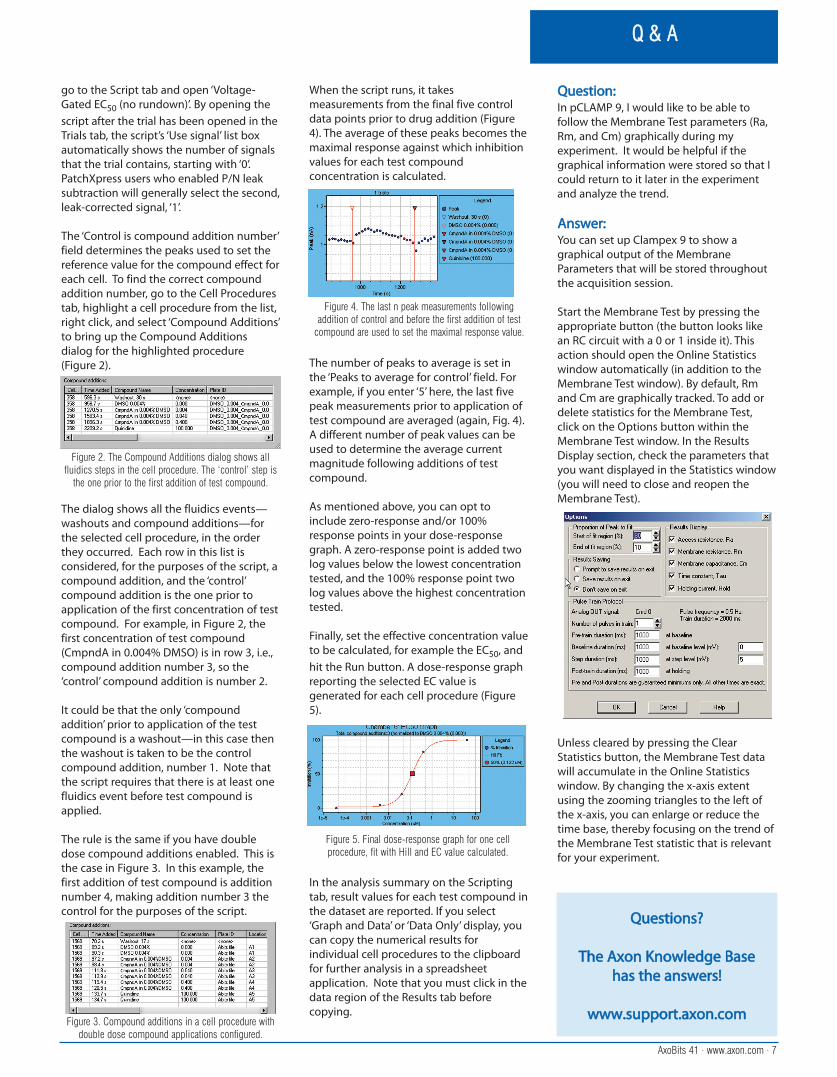
The ‘Control is compound addition number’field determines the peaks used to set thereference value for the compound effect foreach cell. To find the correct compoundaddition number, go to the Cell Procedurestab, highlight a cell procedure from the list,right click, and select ‘Compound Additions’to bring up the Compound Additionsdialog for the highlighted procedure(Figure 2).
The dialog shows all the fluidics events—washouts and compound additions—forthe selected cell procedure, in the orderthey occurred. Each row in this list isconsidered, for the purposes of the script, acompound addition, and the ‘control’compound addition is the one prior toapplication of the first concentration of testcompound. For example, in Figure 2, thefirst concentration of test compound(CmpndA in 0.004% DMSO) is in row 3, i.e.,compound addition number 3, so the‘control’ compound addition is number 2.
It could be that the only ‘compoundaddition’ prior to application of the testcompound is a washout—in this case thenthe washout is taken to be the controlcompound addition, number 1. Note thatthe script requires that there is at least onefluidics event before test compound isapplied.
The rule is the same if you have doubledose compound additions enabled. This isthe case in Figure 3. In this example, thefirst addition of test compound is additionnumber 4, making addition number 3 thecontrol for the purposes of the script.
When the script runs, it takesmeasurements from the final five controldata points prior to drug addition (Figure4). The average of these peaks becomes themaximal response against which inhibitionvalues for each test compoundconcentration is calculated.
The number of peaks to average is set inthe ‘Peaks to average for control’ field. Forexample, if you enter ‘5’ here, the last fivepeak measurements prior to application oftest compound are averaged (again, Fig. 4).A different number of peak values can beused to determine the average currentmagnitude following additions of testcompound.
As mentioned above, you can opt toinclude zero-response and/or 100%response points in your dose-responsegraph. A zero-response point is added twolog values below the lowest concentrationtested, and the 100% response point twolog values above the highest concentrationtested.
Finally, set the effective concentration valueto be calculated, for example the EC50, andhit the Run button. A dose-response graphreporting the selected EC value isgenerated for each cell procedure (Figure5).
In the analysis summary on the Scriptingtab, result values for each test compound inthe dataset are reported. If you select‘Graph and Data’ or ‘Data Only’ display, youcan copy the numerical results forindividual cell procedures to the clipboardfor further analysis in a spreadsheetapplication. Note that you must click in thedata region of the Results tab beforecopying.
QQuueessttiioonn::In pCLAMP 9, I would like to be able tofollow the Membrane Test parameters (Ra,Rm, and Cm) graphically during myexperiment. It would be helpful if thegraphical information were stored so that Icould return to it later in the experimentand analyze the trend.
AAnnsswweerr::You can set up Clampex 9 to show agraphical output of the MembraneParameters that will be stored throughoutthe acquisition session.
Start the Membrane Test by pressing theappropriate button (the button looks likean RC circuit with a 0 or 1 inside it). Thisaction should open the Online Statisticswindow automatically (in addition to theMembrane Test window). By default, Rmand Cm are graphically tracked. To add ordelete statistics for the Membrane Test,click on the Options button within theMembrane Test window. In the ResultsDisplay section, check the parameters thatyou want displayed in the Statistics window(you will need to close and reopen theMembrane Test).
Unless cleared by pressing the ClearStatistics button, the Membrane Test datawill accumulate in the Online Statisticswindow. By changing the x-axis extentusing the zooming triangles to the left ofthe x-axis, you can enlarge or reduce thetime base, thereby focusing on the trend ofthe Membrane Test statistic that is relevantfor your experiment.
AxoBits 41 · www.axon.com · 7
Q & A
Figure 2. The Compound Additions dialog shows allfluidics steps in the cell procedure. The ‘control’ step is
the one prior to the first addition of test compound.
Figure 3. Compound additions in a cell procedure withdouble dose compound applications configured.
Figure 5. Final dose-response graph for one cellprocedure, fit with Hill and EC value calculated.
Figure 4. The last n peak measurements followingaddition of control and before the first addition of test
compound are used to set the maximal response value.
QQuueessttiioonnss??
TThhee AAxxoonn KKnnoowwlleeddggee BBaassee hhaass tthhee aannsswweerrss!!
wwwwww..ssuuppppoorrtt..aaxxoonn..ccoomm

Australia, New ZealandGeneWorks Pty. Ltd.P.O. Box 11Rundle MallAdelaide, SA 5000, AustraliaFreecall: 1800-882-555Ph: +61 8-8234-2644Fax: +61 8-8234-2699Email: [email protected]: www.geneworks.com.au
China, TaiwanCold Spring Biotechnology Web: www.csbiotech.com.tw(Three offices)
Beijing OfficeMr. Leo TaiCold Spring BiotechRoom 1603 (A) Vantone New World PlazaNo. 2 Fu Cheng Men Wai StreetXi Cheng District, Beijing 100037, P.R. ChinaPh: +86 10-6858-8166Fax: +86 10-6858-8166 or -7980Email: [email protected]
Shanghai OfficeCold Spring Biotech158 Hanzhong Road, Room 1310Hanzhong PlazaShanghai 200070, P.R. ChinaPh: +86 21-6353-5972Fax: +86 21-6353-5973Email: [email protected]
Taiwan OfficeMr. Pasteur Tai2F-1, No. 31, Lane 169Kang Ning St.Da Hu Science ParkHsichih City, Taipei Hsien, Taiwan, R.O.ChinaPh: +886 2-2695-9990Fax: +886 2-2692-3410Email: [email protected]
France, BelgiumDIPSI IndustrieImmeuble Vecteur-Sud70-86, avenue de la RépubliqueF-92325 Chatillon Cedex, FrancePh: +33 1-4965-6720Fax: +33 1-4965-6729Email: [email protected]: www.dipsi.com
Germany, AustriaBiozym Scientific GmbHPostfach31833 Hess. Oldendorf, GermanyPh: +49 5152-9020Fax: +49 5152-2070Email: [email protected]: www.biozym.com
IndiaMicro Devices Metrohm Ltd.New No. 13, Old No. 4/1First Avenue, Indira NagarAdyar, Chennai-600 020, IndiaPh: +91 44 24452726 Fax: +91 44 24430384 Email: [email protected]: www.mdml.com
IsraelWestburg (Israel) Ltd.6 Hagoren St., Industrial ParkOmer 84965IsraelPh: +972 8-690-0655Fax: +972 8-690-0650Email: [email protected]: www.westburg.co.il
ItalyM-Medical s.r.l.Via Merendi, 2220010 Cornaredo - MilanoItalyPh: +39 02-93-991-057Fax: +39 02-93-991-001Email: [email protected]: www.mmedical.it
JapanInter Medical Co. Ltd.Inter Bldg.40-4 Imaike 3-chome, Chikusa-kuNagoya 464-0850, JapanPh: +81 52-731-8000Fax: +81 52-731-5050Email: [email protected]: www.intermedical.co.jp
KoreaDae Myung Scientific Co., Ltd.4F DM B/D 128-9 Karak 2-dongSongpa-ku, SeoulKoreaPh: +82 2-458-5835Fax: +82 2-452-1221Email: [email protected]: www.dm4you.com
Singapore, MalaysiaResearch Biolabs Pte Ltd.73 Ayer Rajah Crescent #04-05Ayer Rajah Industrial EstateSingapore 139952Tel: + 65 6777-5366Fax: + 65 6778-5177Email: [email protected]: www.researchbiolabs.com
Spain, PortugalDurviz, s.l.Parque Tecnológico de ValenciaLeonardo da Vinci, 1046980 Paterna (Valencia), SpainPh: +34 96-136-6107Fax: +34 96-136-6168Email: [email protected]: www.durviz.com
SwitzerlandBucher Biotec AGSchützengraben 7CH-4051 Basel, SwitzerlandPh: +41 61-269-1111Fax: +41 61-269-1112Email: [email protected]: www.bucher.ch
The Netherlands, Luxembourg, Denmark,Norway, Sweden, Finland, Iceland, Czech RepublicWestburg B.V.Arnhemseweg 87P.O. Box 2143830 AE Leusden, The NetherlandsPh: +31 33-495-0094Fax: + 31 33-495-1222Email: [email protected]: www.westburg.nl
United Kingdom, IrelandGRI Ltd.Gene HouseQueenborough Lane, Rayne, BraintreeEssex CM7 8TFUnited KingdomPh: +44 1376-332900Fax: +44 1376-344724Email: [email protected]: www.gri.co.uk
United StatesAxon Instruments, Inc.In the U.S., all sales are directly from AxonInstruments. All prices are stated and must be paid in U.S. dollars (US$). FOB Factory,California, U.S.A. All prices are subject tochange without notice.
3280 Whipple Road, Union City, CA 94587 USA Phone: +1 (510) 675-6200 Fax: +1 (510) 675-6300 Email: [email protected] Copyright © 2004 Axon Instruments, Inc.
www.axon.com
DDiissttrriibbuuttoorrss