b a b elevation view - midwest roadside safety … · for the 6x19 iwrc ips cables. notes: scale:...
TRANSCRIPT

28 Spaces @ 75" [1905] = 175'-0" [53340]
75"1905(Typ.)
25°
in the first 75' [22860] downstream of post no. 29.
(1)
(2)
(3)
(4)
(5)
(6)
(7)
(8)
Notes: Impact location for the 2270P is at the centerline of post no. 24.
Paint the downstream bearing plate and BCT cable two different colors.
The BCT anchor posts are placed in 3' [914] holes.
Critical region located between post nos. 21 and 29.
A string potentiometer and tension load cell shall be placed within the upstream anchorage system.
A high-speed digital video camera is to be placed perpendicular to downstream anchor.
Avoid activating vehicle brakes in the first 100' [30480] downstream of post no. 29.
Allow for a minimum lateral clearance of 30' [9144] behind the system
129 28 27 26 25 24 23 22 21 20 19 18 17 16 15 14 13 12 11 10 9 8 7 56 4 3 2
a5 a4 a3 a4 a4 a4 a4 a4 a4 a4 a4 a4 a4 a4 a5
Downstream End
Upstream End
SCALE: 1:225
DS-Anchorage-31in_R5
SHEET:
1 of 15
DWG. NAME.
DATE:
5/25/2012
DRAWN BY:
JGPMidwest Roadside Safety Facility REV. BY:
KAL/RKFUNITS: in.[mm]
Wisconsin DOT Project MGS with Standard Downstream Anchorage System
System Layout
ELEVATION VIEW
PLAN VIEWImpact2270P
[152x305x362] Blockouts
A
and BCT Cable AnchorTubes, Ground Line Strut, Long (Galvanized) Foundation BCT Posts in 6' [1829]
AnchorLine Strut, and BCT Cable Foundation Tubes, Ground Long (Galvanized) BCT Posts in 6' [1829] W6x8.5, 72" [W152x12.6,
1829] Long Posts with 6"x12"x14 1/4"
a6
31"787
B
B
31"
787
40"
1016
32"
812
C
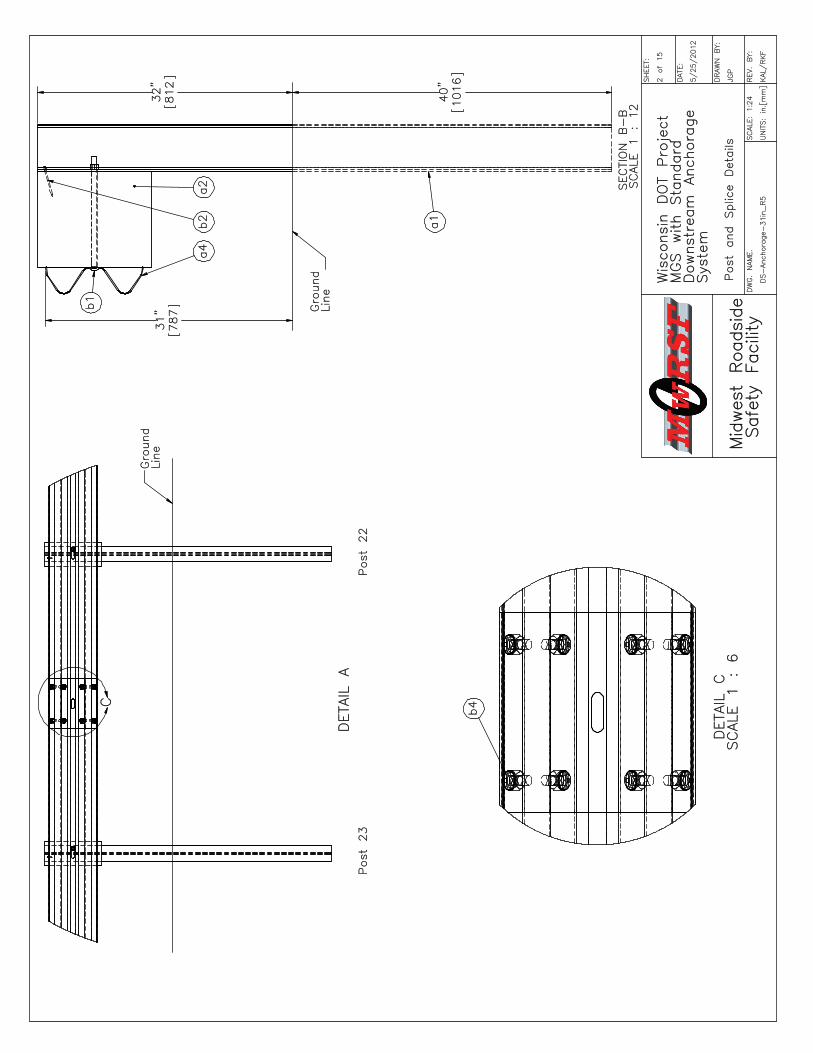
Post 23
DETAIL A
Ground
Line
Post 22
SCALE: 1:24
DS-Anchorage-
31in_R5
SHEET:
2 of 15
DWG. NAME.
DATE:
5/25/2012
DRAWN BY:
JGP
Midwest Roadside
Safety Facility
REV. BY:
KAL/RKF
UNITS: in.[mm]
Wisconsin DOT Project
MGS with Standard
Downstream Anchorage
System
Post and Splice Details
Line
B-B
SCALE 1 : 12
a4
SECTION
b1
a1
a2
Ground
b2
SCALE 1 : 6
DETAIL C
b4

45 3/4"
1162
70"
1778
31"
787
32"
812
SCALE: 1:24
DS-Anchorage-
31in_R5
SHEET:
3 of 15
DWG. NAME.
DATE:
5/25/2012
DRAWN BY:
JGP
Midwest Roadside
Safety Facility
REV. BY:
KAL/RKF
UNITS: in.[mm]
Wisconsin DOT Project
MGS with Standard
Downstream Anchorage
System
Upstream End Rail Details
Ground
Line
F
G
Upstream End Section Detail
Load Cell Assembly
Post 1
EBCT Cable with
c3
Post 2
89 1/2"
2273
DD
H
D-D
SECTION
Line
a5
b3
c2
c1
Ground
b5

b5
DETAIL H
c8
b5 Ground Line
DETAIL F
c4
c3c7
e3
Ground Line
SCALE: 1:6
DS-Anchorage-
31in_R5
SHEET:
4 of 15
DWG. NAME.
DATE:
5/25/2012
DRAWN BY:
JGP
Midwest Roadside
Safety Facility
REV. BY:
KAL/RKF
UNITS: in.[mm]
Wisconsin DOT Project
MGS with Standard
Downstream Anchorage
System
Anchor Details
c10
DETAIL G
c11
DETAIL E
c6
b5
c9

45 3/4"
1162
Downstream End Section Detail
Post 28
Ground Line
c5
c3
a6
Post 29
89 1/2"
2273
SCALE: 1:24
DS-Anchorage-
31in_R5
SHEET:
5 of 15
DWG. NAME.
DATE:
5/25/2012
DRAWN BY:
JGP
Midwest Roadside
Safety Facility
REV. BY:
KAL/RKF
UNITS: in.[mm]
Wisconsin DOT Project
MGS with Standard
Downstream Anchorage
System
Downstream End Rail Details

Note:
6x25 IWRC IPS cables meet the minimum breaking
strength of 42.7 kips [190 kN] and may be
substituted for the 6x19 IWRC IPS cables.
(1)
e3e2
e1e4
g1
d1
f1
80 1/16"
2033
SCALE: 1:8
DS-Anchorage-
31in_R5
SHEET:
6 of 15
DWG. NAME.
DATE:
5/25/2012
DRAWN BY:
JGP
Midwest Roadside
Safety Facility
REV. BY:
KAL/RKF
UNITS: in.[mm]
Wisconsin DOT Project
MGS with Standard
Downstream Anchorage
System
Modified BCT Cable with Load
Cell Assembly
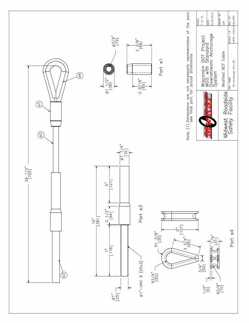
29 1/2"
750
Dimensions are not necessarily representative of the part;
Note:(1)see final part for actual dimensions
e3
e4
e2e1
1"-UNC 8 [25x3]
Part e3
1 1/4"
32
1"
25
7"
178
2 1/2"
64
5"
127
15"
381
SCALE: 1:4
DS-Anchorage-
31in_R5
SHEET:
7 of 15
DWG. NAME.
DATE:
5/25/2012
DRAWN BY:
JGP
Midwest Roadside
Safety Facility
REV. BY:
KAL/RKF
UNITS: in.[mm]
Wisconsin DOT Project
MGS with Standard
Downstream Anchorage
System
Modified BCT Cable
Part e1
Part e4
3 3/8"
86
2 9/16"
65
5"
127
R3/4"
20
R1 3/8"
35
3 3/4"
95
3/4"
20
1 1/2"
38
3/4"
19
1 1/4"
31
1/4"
6
R3/8"
10

6 1/2"
165
3 3/4"
95
5 3/8"
137
Part f1
Part g1
SCALE: 1:4
DS-Anchorage-
31in_R5
SHEET:
8 of 15
DWG. NAME.
DATE:
5/25/2012
DRAWN BY:
JGP
Midwest Roadside
Safety Facility
REV. BY:
KAL/RKF
UNITS: in.[mm]
Wisconsin DOT Project
MGS with Standard
Downstream Anchorage
System
Shackle and Eye Nut
R1 1/4"
32
R2 5/8"
67
4"
102
3 7/8"
98
1 3/8"
35
R1 5/8"
41
R3"
76
2"
52
R1 9/16"
40
1 1/2"
38

1 3/4"
44
7 1/8"
1816"
152
3/4"
19
SCALE: 1:20
DS-Anchorage-
31in_R5
SHEET:
9 of 15
DWG. NAME.
DATE:
5/25/2012
DRAWN BY:
JGP
Midwest Roadside
Safety Facility
REV. BY:
KAL/RKF
UNITS: in.[mm]
Wisconsin DOT Project
MGS with Standard
Downstream Anchorage
System
Post Nos. 3-27 Details
Line Post
Part a1
Blockout
Part a2
Alternate Blockout Option -
6"x4"x14 1/4" [152x102x362] Blockout
with 6"x8"x14 1/4" [152x203x362] Blockout
3/4"
19
6"
152
1 3/4"
44
7 1/8"
181
14 1/4"
362
12"
305
6"x8"x14 1/4"
[152x203x362] Blockout
14 1/4"
362
8"
203
3/4"
19
1 3/4"
44
7 1/8"
181
6"
152
12"
305
14 1/4"
362
72"
1829
1/4"
61"
251"
25
3/4"
19
7 1/8"
181
3/4"
19
6"x4"x14 1/4"
[152x102x362] Blockout
14 1/4"
362
4"
102
3/4"
19
6"
152
7 1/8"
181
1 3/4"
44

1 1/8"
29
4"
102
3"
76
8"
203
8"
203
1/8"
4
2 3/8"
60
BCT MGS Timber Post
Part c1
Foundation Tube
Part c2
Anchor Bracket Bearing Plate
Part c4
SCALE 1:8
SCALE: 1:16
DS-Anchorage-
31in_R5
SHEET:
10 of 15
DWG. NAME.
DATE:
5/25/2012
DRAWN BY:
JGP
Midwest Roadside
Safety Facility
REV. BY:
KAL/RKF
UNITS: in.[mm]
Wisconsin DOT Project
MGS with Standard
Downstream Anchorage
System
BCT Timber Post &
Foundation Tube Details
3/16"
5
72"
1829
4"
102
17"
432
8"
203
1"
25
BCT Post Sleeve
Part c7
SCALE 1:4
6"
152
7 1/8"
181
23 7/8"
606
2 3/4"
70 3/4"
19
5 1/2"
140
7/8"
22
17 1/2"
445
46"
1168
3 3/4"
95
2 1/2"
64
7 1/2"
191
5/8"
16
3"
76
1"
25
3/4"
19
6"
152
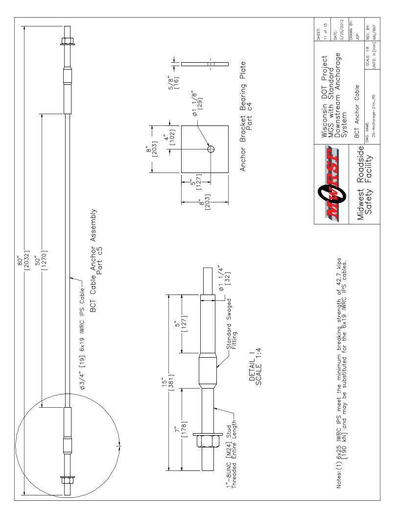
(1)6x25 IWRC IPS meet the minimum breaking strength of 42.7 kips
[190 kN] and may be substituted for the 6x19 IWRC IPS cables.
Notes:
SCALE: 1:8
DS-Anchorage-
31in_R5
SHEET:
DWG. NAME.
DATE:
5/25/2012
DRAWN BY:
JGP
Midwest Roadside
Safety Facility
11 of 15
REV. BY:
KAL/RKF
UNITS: in.[mm]
Wisconsin DOT Project
MGS with Standard
Downstream Anchorage
System
BCT Anchor Cable
Fitting
SCALE 1:4
DETAIL I
Standard Swaged
1"-8UNC [M24] Stud
Threaded Entire Length
7"
178
5"
127
15"
381
1 1/4"
32
BCT Cable Anchor Assembly
Part c5
3/4" [19] 6x19 IWRC IPS Cable
I
80"
2032
50"
1270
5/8"
16
Anchor Bracket Bearing Plate
Part c4
8"
203
8"
203
1 1/8"
29
5"
127
4"
102

4"
102
1 1/2"
38
75"
1905
3"
76
6"
152
R1/2"
13
(Typ.)
7/8"[22] x 2"[51] Slot
3"
76
FRONT VIEW
Strut and Yoke Assembly
Part c3
Yoke
Anchor Bracket End Plate
SCALE 1:8
Anchor Bracket
(FPA01)
Part c6
SCALE 1:8
SCALE: 1:16
DS-Anchorage-
31in_R5
SHEET:
12 of 15
DWG. NAME.
DATE:
5/25/2012
DRAWN BY:
JGP
Midwest Roadside
Safety Facility
REV. BY:
KAL/RKF
UNITS: in.[mm]
Wisconsin DOT Project
MGS with Standard
Downstream Anchorage
System
Ground Strut &
Anchor Bracket Details
4 1/4"
108
1/2"
13
R1/2"
13
End Plate
Anchor Bracket
1/4"[6.4]
5 1/2"[140]
Three Sides
13/16"
21
3/4"
19 (Typ.)
5 5/8"
143
1 3/4"
44
55°
Strut
Yoke
78"
1981
3/16"[4.8]
PLAN VIEW
3/16"[4.8]
8 1/2"
216 3/16"
5
R5/16"
8 (Typ.)
5 1/2"
140
Strut
6"x3" [152x76] 10 Gauge [3.4]
67"
1702
2"
51
4"
102
4"
102
4"
102
2"
51
3/8"
10
3"
76
1 1/2"
38
2 3/4"
70
1 3/8"
35
1 1/8"
29
43 3/4"
1111
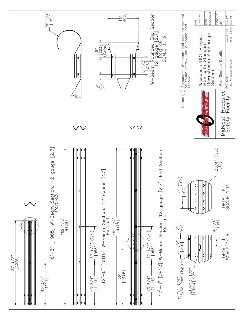
(1)If rounded W-beam end section cannot
be found locally use a spoon end
section.
Notes:
4"
102(Typ.)
8 1/2"
216
2"
51
4 1/4"
108
43 3/4"
1111
37 1/2"
953
(Typ.)
59"
1499
43 3/4"
1111
37 1/2"
953
(Typ.)
2"
51
8 1/2"
216
8"
203
(Varies)
J
87 1/2"
2223
SCALE: 1:30
DS-Anchorage-
31in_R5
SHEET:
13 of 15
DWG. NAME.
DATE:
5/25/2012
DRAWN BY:
JGP
Midwest Roadside
Safety Facility
REV. BY:
KAL/RKF
UNITS: in.[mm]
Wisconsin DOT Project
MGS with Standard
Downstream Anchorage
System
Rail Section Details
6'-3" [1905] W-Beam Section, 12 gauge [2.7]
Part a3
DETAIL K
SCALE 1:15
3/4" (Typ.)
[19]
1"x1 1/4"
[25x32] Slot (Typ.)
SCALE 1:15
DETAIL J
3/4"x2 1/2"
[19x64] Slot
K
162 1/2"
4128
R6 1/4"
159
30°
12'-6" [3810] W-Beam Section, 12 gauge [2.7]
Part a4
12'-6" [3810] W-Beam Section, 12 gauge [2.7], End Section
Part a5
162 1/2"
4128
W-Beam Rounded End Section
12 gauge [2.7]
Part a6
SCALE 1:15
16"
406

Item
No.
QTY.
Description
Material Specification
Hardware Guide
a1
25
W6x8.5 6' Long [W152x12.6 1829] Steel Post
ASTM A992 Min. 50 ksi [345 MPa]
(W6x9 ASTM A36 Min. 36 ksi [248 MPa])
PWE06
a2
25
6x12x14 1/4" [152x305x362] Blockout
SYP Grade No. 1 or better
PDB10a-b
a3
16'-3" [1905] W-Beam MGS Section
12 gauge [2.7] AASHTO M180
RWMO1a
a4
12
12'-6" [3810] W-Beam MGS Section
12 gauge [2.7] AASHTO M180
RWM04a
a5
212'-6" [3810] W-Beam MGS End Section
12 gauge [2.7] AASHTO M180
RWM14a
a6
1W-Beam Rounded End Section
12 gauge [2.7] AASHTO M180
RWE03a
b1
25
5/8" Dia. x 14" Long [M16x356] Guardrail Bolt and Nut
Bolt ASTM A307, Nut ASTM A563 A
FBB06
b2
25
16D Double Head Nail
--
b3
45/8" Dia. x 10" [M16x254] Long Guardrail Bolt and Nut
Bolt ASTM A307, Nut ASTM A563 A
FBB03
b4
116
5/8" Dia. x 1 1/2" Long [M16x38] Guardrail Bolt and Nut
Bolt ASTM A307, Nut ASTM A563 A
FBB01
b5
46
5/8" [16] Dia. Flat Washer
ASTM F844 or SAE Grade 2 Steel
FWC16a
c14
BCT Timber Post - MGS Height
SYP Grade No. 1 or better
PDF01
c24
72" [1829] Long Foundation Tube
ASTM A53 Grade B
PTE06
c32
Strut and Yoke Assembly
ASTM A36 Steel Galvanized
-
c42
8x8x5/8" [203x203x16] Anchor Bearing Plate
ASTM A36 Steel
FPB01
c51
BCT Anchor Cable Assembly
3/4" [19] 6x19 IWRC IPS Galvanized
Wire Rope
FCA01
c62
Anchor Bracket Assembly
ASTM A36 Steel
FPA01
c72
2 3/8" [60] O.D. x 6" [152] Long BCT Post Sleeve
ASTM A53 Grade B Schedule 40
FMM02
c84
5/8" Dia. x 10" [M16x254] Long Hex Head Bolt and Nut
Bolt ASTM A307, Nut ASTM A563 A
FBX16a
c916
5/8" Dia. x 1 1/2" Long [M16x38] Hex Head Bolt and Nut
Bolt ASTM A307, Nut ASTM A563 A
FBX16a
c10
47/8" Dia. x 7 1/2" [M22x191] Long Hex Head Bolt and Nut
Bolt ASTM A307, Nut ASTM A563 A
FBX22a
c11
87/8" [22] Dia. Flat Washer
ASTM F844 or SAE Grade 2 Steel
FWC22a
SCALE: NONE
DS-Anchorage-
31in_R5
SHEET:
14 of 15
DWG. NAME.
DATE:
5/25/2012
DRAWN BY:
JGP
Midwest Roadside
Safety Facility
REV. BY:
KAL/RKF
UNITS: in.[mm]
Wisconsin DOT Project
MGS with Standard
Downstream Anchorage
System
Bill of Materials

SCALE: NONE
DS-Anchorage-
31in_R5
SHEET:
15 of 15
DWG. NAME.
DATE:
5/25/2012
DRAWN BY:
JGP
Midwest Roadside
Safety Facility
REV. BY:
KAL/RKF
UNITS: in.[mm]
Wisconsin DOT Project
MGS with Standard
Downstream Anchorage
System
Bill of Materials Continued
Item
No.
QTY.
Description
Material Specification
d1
1TLL-
50K-PTB Load Cell
NA
e12
115-HT Mechanical Splice - 3/4" [19] Dia.
As Supplied
e22
3/4" [190] 6x19 IWRC IPS Wire Rope
IPS Galvanized
e34
BCT Anchor Cable End Swage Fitting
SAE Grade 5 - Galvanized
e42
Crosby Heavy Duty HT-
3/4" [19] Dia. Cable Thimble
As Manufactured
f12
Crosby G2130 or S2130 Bolt Type Shackle - 1 1/4" [32] Dia. with thin head bolt,
nut, and cotter pin, Grade A, Class 3
Stock Nos. 1019597 and 1019604 - As Supplied
g1
2Chicago Hardware Drop-Forged Heavy Duty Eye Nut - Drilled and Tapped 1 1/2" [38]
Dia. - UNF 12 [M36]
As Supplied, Stock No. 107