b r owners' group - nrc: home page
TRANSCRIPT

K. S. Putnam, Chairman
B R OWNERS' GROUP Tel: (319) 851 7238
[email protected] Management Company * Duane Arnold Energy Center * 3277 DAEC Road * Palo, IA, 52324
Project Number 691BWROG-04021August 5, 2004
US Nuclear Regulatory CommissionDocument Control DeskWashington, D.C. 20852-2738
SUBJECT: NRC ACCEPTED VERSION OF IMPROVED BPWS CONTROL ROD INSERTIONPROCESS LTR, NEDO-33091-A
Reference: 1. USNRC, "Safety Evaluation For Licensing Topical Report (LTR) NEDO-33091, "ImprovedBPWS Control Rod Insertion Process" (TAC No. MB9642)
Attachment: BWR Owners' Group Licensing Topical Report, Improved BPWS Control Rod InsertionProcess, NEDO-33091-A (non-proprietary), Revision 2, July 2004.
In accordance with the Reference 1, this letter transmits (attached) the NRC accepted version of thesubject LTR. Per Reference 1, the attached LTR version incorporates the NRC cover letter and theSafety Evaluation between the title page and the abstract. The Table of Contents has been updated suchthat new information can be readily located. This version has added two appendices of historical reviewinformation (the associated NRC Requests for Additional Information and their accepted responses, andthe BWROG comments on the draft NRC SE). All of the original report pages have been replaced withpages that include an "-A" in the report identification number.
Very truly yours,
K.S. PutnamBWR Owners' Group ChairmanTel: (319) 851-7238Fax: (319) 851-7364ken.putnam @nmcco.com
cc: BWROG Primary RepresentativesBWROG Executive Oversight CommitteeBWROG BPWS CommitteeJ. Conen, BWROG Vice-ChairmanNRC, Document Control DeskT.G. Hurst, GEJ. Tuttle, GE

GE Nuclear Energy
NEDO-33091-ARevision 2
Class IDRF 0000-0008-3745
July 2004i
NRC Accepted
BWR Owners' Group Licensing Topical Report
Improved BPWS :
Control Rod Insertion Process,A

GE Nuclear EnergyGeneral Electric Company175 Curtner Avenue, San Jose, CA 95125
NEDO-33091-ARevision 2
Class IDRF 0000-0008-3745
July 2004
NRC Accepted
BWR Owners' Group,Licensing Topical Report
Improved BPWSControl Rod Insertion Process
Approved by:J. Tee, Project Manager

NEDO-33091-A, Revision 2
IMPORTANT NOTICE REGARDING THECONTENTS OF THIS REPORT
Please Read Carefully
DISCLAIMER
The only undertakings of the General Electric Company (GE) respecting information in thisdocument are contained in the contract between the company receiving this document and GE.Nothing contained in this document shall be construed as changing the applicable contract. Theuse of this information by anyone other than a customer authorized by GE to have this document,or for any purpose other than that, for which it is intended, is not authorized. With respect to anyunauthorized use, GE makes no representation or warranty, and assumes no liability as to thecompleteness, accuracy or usefulness of the information contained in this document, or that itsuse may not infringe privately owned rights.
CHANGES FROM PREVIOUS VERSION
In accordance with the NRC cover letter to the SAFETY EVALUATION FOR LICENSINGTOPICAL REPORT (LTR) NEDO-33091, "IMPROVED BPWS CONTROL ROD INSERTIONPROCESS," (TAC No. MB9642), this report is the (NRC) accepted version of the LTR. Thisversion incorporates the NRC cover letter and the Safety Evaluation between the title page andthe abstract. The Table of Contents has been updated such that new information can be readilylocated. This version has added two appendices of historical review information (the associatedNRC Requests for Additional Information and their accepted responses, and the BWROGcomments on the draft NRC SE). All of the original report pages have been replaced with pagesthat include a "-A" in the report identification number. The technical content in the body of thisLTR has not changed, and thus, the revision number has not changed.
i

NW*
UNITED STATESNUCLEAR REGULATORY COMMISSION
WASHINGTON, D.C. 20555-01
June 16, 2004
Mr. Kenneth Putnam, ChairmanBWR Owners GroupNuclear Management CompanyDuane Arnold Energy Center3277 DAEC Rd.Palo, IA 52324
SUBJECT: SAFETY EVALUATION FOR LICENSING TOPICAL REPORT (LTR)NEDO-33091, IMPROVED BPWS CONTROL ROD INSERTION PROCESS"(TAC NO. MB9642)
Dear Mr. Putnam:
On June 6, 2003, and supplemented on April 21, 2004, the Boiling Water Reactors OwnersGroup (BWROG) submitted LTR NEDO-33091, "Improved BPWS Control Rod InsertionProcess," to the staff for review and approval. On May 10, 2004, an NRC draft safetyevaluation (SE) regarding our approval of NEDO-33091 was provided for your review andcomments. By telecon on June 3, 2004, the BWROG provided minor editorial comments. Thestaff has incorporated the BWROG's comments into the final SE enclosed with this letter.
The staff has found LTR NEDO-33091 acceptable for referencing in licensing applications forboiling water reactors to the extent specified and under the limitations delineated in the LTRand in the enclosed SE. The SE defines the basis for acceptance of the LTR.
Our acceptance applies only to matters approved in the subject LTR. We do not intend torepeat our review of the acceptable matters described in the LTR. When the LTR appears as areference in license applications, our review will ensure that the material presented applies tothe specific plant involved. License amendment requests that deviate from this LTR will besubject to a plant-specific review in accordance with applicable review standards.
In accordance with the guidance provided on the NRC web site, we request that the BWROGpublish an accepted version of this LTR within three months of receipt of this letter. Theaccepted version shall incorporate this letter and the enclosed SE between the title page andthe abstract. It must be well indexed such that information is readily located. Also, it mustcontain in appendices historical review information, such as questions and accepted responses,draft SE comments, and original report pages that were replaced. The accepted version shallinclude a "-Am (designated accepted) following the report identification symbol.
K. Putnam -2 -
If the NRC's criteria or regulations change so that its conclusion in this letter, that the LTR isacceptable, are invalidated, the BWROG and/or the applicant referencing the LTR will beexpected to revise and resubmit its respective documentation, or submit justification for thecontinued applicability of the LTR without revision of the respective documentation.
Sincerely,
He rt N. Berkow, DirectorProject Directorate IVDivision of Ucensing Project ManagementOffice of Nuclear Reactor Regulation
Project No. 691
Enclosure: Safety Evaluation
cc w/encl: See next page

BWR Owners Group Project No. 691
cc:Mr. Joseph E. ConenVice Chairman, BWR Owners GroupDTE Energy - Fermi 2200 TAC6400 N. Dixie HighwayNewport, Ml 48166
Mr. J. A. Gray, Jr.Regulatory Response Group ChairmanBWR Owners GroupEntergy Nuclear Northeast440 Hamilton Avenue Mail Stop 12CWhite Plains, NY 10601-5029
Mr. H. Lewis SumnerSouthern Nuclear Company40 Inverness Center ParkwayP.O. Box 1295Birmingham, AL 35242
Mr. Carl D. TerryVice President, Nuclear EngineeringNine Mile Point - StationOPS Building/2nd FloorP.O. Box 63Lycoming, NY 13093
Mr. William A. EatonENTERGYGrand Gulf Nuclear StationP.O. Box 756Port Gibson, MS 39150
Mr. Mark ReddemanVice President EngineeringPoint Beach Nuclear Plant6610 Nuclear RoadTwo Rivers, WI 54241
Mr. Richard LibraDTE EnergyFermi 2M/C 280 OBA6400 North Dixie HighwayNewport, Ml 48166
Mr. James F. KlapprothGE Nuclear EnergyMWC 706175 Curtner AvenueSan Jose, CA 95125
Mr. Thomas G. HurstGE Nuclear EnergyMJC 782175 Curtner AvenueSan Jose, CA 95125
Mr. Thomas A. GreenGE Nuclear EnergyMWC 782175 Curtner AvenueSan Jose, CA 95125
Mr. James MeisterExelonCornerstone II at Cantera4300 Winfield RoadWarrenville, IL 60555

*s- v
UNITED STATESNUCLEAR REGULATORY COMMISSION
WASHINGTON, D.C. 20555-0001
SAFETY EVALUATION BY THE OFFICE OF NUCLEAR REACTOR REGULATION
LICENSING TOPICAL REPORT NEDO-33091. IMPROVED BPWS CONTROL
ROD INSERTION PROCESS
BOILING WATER REACTOR OWNERS GROUP (BWROG)
PROJECT NO. 691
1.0 INTRODUCTION
By letter dated June 6, 2003, as supplemented by letter dated April 21, 2004, the BWROGrequested the NRC to review its licensing topical report (TR) NEDO-33091, "Improved BPWS[Banked Position Withdraw Sequence] Control Rod Insertion Process.' Both the original BPWSprocess previously approved by the staff and the proposed improved process, are designed tominimize reactivity insertion during a postulated design basis control rod drop accident (CRDA).
Throughout its operating cycle, a boiling water reactor (BWR) experiences various startup,normal, and shutdown operations. Control rods are also moved due to fuel bum-up, powermaneuvers, and normal operational occurrences. This rod movement could potentially result ina decoupled control rod that's stuck in the core, followed by a subsequent control rod drop,which would lead to a high reactivity insertion in a small region of the core. For large looselycoupled cores, a significant shift in the spatial power generation could occur during the courseof this excursion. Utilizing rod pattern control systems, i.e., rod worth minimizer, rod sequencecontrol system or rod pattern controller, the BPWS was developed to reduce the maximumcontrol rod worth during the startup and shutdown processes. The originalstandard BPWSprocess currently requires control rods to be moved in banked positions, even during theshutdown process after the low power set point (LPSP) is reached. This requirement results inthe control of rod movement through many steps, when there is an extremely low possibility forthe control rod to drop out of the core. Therefore, the improved BPWS proposes the one-stepfull insertion of control rods without banking after the reactor power is below LPSP.
2.0 REGULATORY BASIS
CRDA is the design basis accident for the subject LTR. In order to minimize the impact of aCRDA, the BPWS process was developed to minimize control rod reactivity worth for BWR2-6.The proposed improved BPWS further simplifies the control rod insertion process, and in orderto evaluate it, the staff followed the guidelines of Standard Review Plan Section 15.4.9, andreferred to General Design Criterion 28 of Appendix A to 10 CFR Part 50 as its regulatoryrequirement.

-2-
3.0 TECHNICAL EVALUATION
The originalstandard BPWS was developed to minimize the control rod worth and mitigate theconsequences of a CRDA from occurring during startup. This procedure also directly applies tothe control rod insertion sequence during the shutdown routine, after power is lower than theLPSP. The BWROG and GE Nuclear Energy (GENE) found that this approach, whileconservative, requires unnecessary control rod movements during the shutdown process. Theprocedural requirements on the operator also increases the risk of incorrect control rodmovement, and causes additional wear on the rod and rod drive hardware systems. Since thepossibility of having a decoupled control rod is extremely low during the shutdown process,GENE is proposing the improved BPWS, which allows control rods to be fully inserted in asingle step during the shutdown process.
The improved BPWS proposes the following changes to the operational procedures:
1. Before reducing power to the LPSP, operators shall confirm control rod couplingintegrity for all rods that are fully withdrawn. Control rods that have not been confirmedcoupled and are in intermediate positions must be fully inserted prior to power reductionto the LPSP. No action is required for fully-inserted control rods.
If a shutdown is required and all rods, which are not confirmed coupled, cannot be fullyinserted prior to the power dropping below the LPSP, then the originaVstandard BPWSmust be adhered to.
2. After reactor power drops below the LPSP, rods may be inserted from notch position 48to notch position 00 without stopping at intermediate positions. However, GENErecommends that operators should insert rods in the same order as specified for theoriginal/standard BPWS as much as reasonably possible. If a plant is in the process ofshutting down following improved BPWS with the power below the LPSP, no control rodshall be withdrawn unless the control rod pattem Is in compliance with standard BPWSrequirements.
All other control rod operational requirements are unchanged and continue to apply. Theproposed changes may alter the technical specifications of certain plants; GENE has Identifiedthe potentially affected areas in the standard technical specifications. The specific changes foreach plant implementing the improved BPWS will be determined on a case-by-case basis.
The basis of the improved BPWS is the assumption that a CRDA can only be caused by astuck rod which is decoupled from the control rod drive (CRD). No single failure of a BWR CRDmechanical or hydraulic system can cause a control rod to drop completely out of the reactorcore during the reactor shut-down process. In its April 21, 2004, response to the staff's requestfor additional information (RAI), the BWROG/GENE referred the staff to Final Safety AnalysisReport (FSAR) sections, isometric drawings, and hydraulic schematics describing the CRDhydraulic unit design, control rod assembly configuration, and postulated CRD failure modesand effects scenarios from the FSARs for Oyster Creek (BWR/2), Monticello (BWR/3), Limerick(BWR/4), LaSalle (BWRI5), and Perry (BWR/6). The staff's review considered CRD hydraulicsystems from plants of various BWR designs, and found that the CRD systems of BWRI2through BWR/6 designs are very similar with respect to the mechanisms for rod insertion,

-3-
withdrawal, and locking. The staff found that during a reactor shutdown process for alloperating BWRs when each control rod is given an insert signal, there exists no single failure ofthe CRD hydraulic or mechanical system that could result in a control rod withdrawal out of thecore of more than six inches (equivalent to one CRD index tube drive notch length). Therefore,the staff agrees with the BWROG/GENE's assessment regarding the possible cause of aCRDA during the shutdown process after reactor power is below the LPSP since the technicalbasis, as cited above, is sound and acceptable.
Implementation of the improved BPWS requires two major operating procedure changes. Therequirement for operators to confirm control rod coupling integrity for all rods fully withdrawn willensure proper coupling during the control rod insertion process and any possible rod withdrawalafter reactor power drops below LPSP. The proposed procedure for the full insertion of allunconfirmed control rods prior to LPSP will prevent the possibility of a decoupled control roddropping out during the control rod maneuvers. If all unconfirmed control rods cannot be fullyinserted prior to the LPSP, the use of the standard BPWS will become the conservative fallback position, since the risk of a CRDA occurring using the improved BPWS will be no differentthan the originalstandard BPWS using this procedure.
After reactor power drops below the LPSP, the improved BPWS allows the full insertion of eachcontrol rod without banking. This simplification of the control rod insertion process helps toreduce the number of control rod insertion steps. Since all unconfirmed control rods have beeninserted, it is highly unlikely for a CRDA to occur while confirmed rods are being insertedwithout banking. Therefore, the improved BPWS will have the same level of safety assuranceas the previously approved standard BPWS process. Should the operator decide to reverse theshutdown process, the improved BPWS does not allow for the withdrawal of any control rods,unless the control rod pattern meets the standard BPWS requirements. This ensures that allcontrol rods are always banked for withdrawal.
The improved BPWS's single step full insertion also reduces the insertion time of each rod,which may induce a necessary increase in other procedures or processes to accommodate thisrapid change. During telephone conferences, the staff requested additional information fromthe BWROG/GENE regarding the impact of the accelerated shut-down process on otherprocedures. The BWROG/GENE examined its process and requirements, and concluded in itsRAI response on April 21, 2004, that the improved BPWS process does not adversely affect thenormal shutdown processes, since the operating procedures will remain to be bounded by themost limiting (fastest negative reactivity) control rod insertion scenario (RAI #3). In addition,pressure-temperature effects, as in the cooldown process for example, are accounted for andcontrolled by controlling reactor dome pressure, coolant flow and coolant temperature.
4.0 CONCLUSIONS
The BWROG/GENE has proposed an improved BPWS process which allows for the single stepfull insertion of control rods during shutdown, when the reactor power is lower than the LPSP.The staff has completed Its review of the subject LTR, and concluded that the proposed changeis acceptable and applicable to BWR/2-6 with originalstandard BPWS already implemented.

-4-
Plants. electing to implement the improved BPWS must reflect the changes in their operatingprocedure. If the technical specification of a plant is impacted or needs to be updated, anamendment submittal to the NRC will be required.
Principal Contributor: Shanlai Lu
Date: June 16, 2004

NEDO-33091-A, Revision 2
TABLE OF CONTENTS
PageNRC Cover Letter With Enclosed Safety Evaluation
ACRONYMS and ABBREVIATIONS .................................... ...................... iii
Executive Summary ........................................................... iv
Acknowledgments ............................................................ v
1. Background.......................................................................................................................... 1-1
2. Introduction . . .2-1
3. Standard Technical Specifications Addressing BPWS and RWMIRPC ... 3-1
4. Safety and Technical Evaluations . . .4-1
5. Plant Implementation . . .5-1
6. Prototypical Technical Specifications Changes . . .6-16.1 NUREG 1433 BWR/4 STS Change .6-16.2 NUREG 1434 BWR/6 STS Change .6-1
7. Safety And Plant Benefits ... ........................................................ 7-17.1 Reactivity Management .......................................................... 7-17.2 Human Performance .......................................................... 7-17.3 Scram Avoidance .......................................................... 7-17.4 Equipment Duty .......................................................... 7-1
8. References .......................................................... 8-1
Appendix A Applicable Standard Technical Specifications . ..................................................... A-1A.I NUREG 1433 BWR/4 STS......................................................................................... A-1A.2 NUREG 1434 BWR/6 STS......................................................................................... A-3
Appendix B NRC Requests For Additional Information And Accepted Responses ... B-1
Appendix C BWROG Comments On The Draft Safety Evaluation . .......................................... C-i
..

NEDO-33091-A, Revision 2
ACRONYMS AND ABBREVIATIONS
APRM Average Power Range Monitor
BPWS Banked Position Withdrawal Sequence
BWR Boiling Water Reactor
BWROG Boiling Water Reactor Owners Group
CRD Control Rod Drive
CRDA Control Rod Drop Accident
IRM Intermediate Range Monitor
LCO Limiting Condition of Operation
LPSP Low Power Setpoint
LTR Licensing Topical Report
NRC Nuclear Regulatory Commission
OLTP Original Licensed Thermal Power
RAI Request for Additional Information
RPC Rod Pattern Controller
RPCS Rod Pattern Control System
RSCS Rod Sequence Control System
RTP Rated Thermal Power
RWM Rod Worth Minimizer
SDM Shutdown margin
SOE Single Operator Error
STS Standard Technical Specifications
TS Technical Specifications
TSTF Technical Specification Task Force
iii

NEDO-33091-A, Revision 2
EXECUTIVE SUMMARY
This generic Licensing Topical Report (LTR) presents an improved Banked Position WithdrawalSequence (BPWS) for performing reactor shutdowns. This report justifies modifying therequirements of the Standard Technical Specifications (STS) relative to the applicability of thesystems used to adhere to the BPWS during the reactor shutdown process (i.e., control rods arespecifically being inserted to achieve shutdown at a power level less than the low power setpoint(LPSP)). The proposed improvement to the reactor shutdown process allows each control rod tobe fully inserted to position 00 in one step instead of banking (e.g., 48-12-84-00) below theLPSP. To utilize this version of the BPWS process, it is required that control rods that have notbeen confirmed to be coupled, are fully inserted prior to reducing power below the LPSP. TheBPWS control rod groups are unchanged.
The BPWS, as currently implemented, limits the potential reactivity increase from a postulatedControl Rod Drop Accident (CRDA) during reactor startups and shutdowns below the LPSP(generically based on 10% of original licensed thermal power). During the reactor shutdownprocess, confirming that control rods are coupled prior to decreasing power below the LPSPeliminates the postulated scenario for a CRDA, and thus, the CRDA would no longer be acredible event.
Modifying plant Technical Specifications (TS) and/or their Bases to reflect the use of theimproved BPWS process would allow control rods to be fully inserted in a single step during thereactor shutdown process below the LPSP. This provides the following benefits:
* Allows the plant to reach the all-rods-in condition prior to significant reactor cool down,which reduces the potential for a re-criticality as the reactor cools down;
* Reduces the potential for an operator reactivity control error by reducing the total numberof control rod manipulations;
* Minimizes the need for manual scrams during plant shutdowns, resulting in less wear onControl Rod Drive (CRD) system components and CRD mechanisms; and
* Eliminates unnecessary control rod manipulations at low power, resulting in less wear onReactor Manual Control and CRD system components.
iv

NEDO-33091-A, Revision 2
ACKNOWLEDGMENTS
The following individuals contributed significantly to the development, verification, and reviewof this report:
J. L. CasillasA. K. ChungR. E. EngelG. D. GallowayE. Y. GiboM.E. HardingR. LinfordI. NirN. SadeghiK. T. SchaeferE. G. ThackerP. T. TranG. A. Watford
v
NEDO-33091-A, Revision 2
1. BACKGROUND
The design basis reactivity insertion event for the BWR is the Control Rod Drop Accident(CRDA). From Section S.2.2.3.1 of Reference 1, the CRDA scenario postulates the following:
(a) Reactor is at a control rod pattern corresponding to maximum incremental rod worth.
(b) Rod pattern control systems (Rod Worth Minimizer, Rod Sequence Control System orRod Pattern Controller) or operators are functioning within the constraints of the BankedPosition Withdrawal Sequence (BPWS). The control rod that results in the maximumincremental reactivity worth addition at any time in core life under any operatingcondition while employing the BPWS becomes decoupled from the control rod drive.
(c) Operator selects and withdraws the drive of the decoupled rod along with the otherrequired control rods assigned to the Banked-position group such that the proper coregeometry for the maximum incremental rod worth exists.
(d) Decoupled control rod sticks in the fully inserted position.
(e) Control rod becomes unstuck and drops at the maximum velocity determined fromexperimental data (3.1 1 feet per second).
(f) Reactor goes on a positive period and initial power burst is terminated by the Dopplerreactivity feedback.
(g) APRM 120% power signal scrams reactor (conservative; in startup mode APRM scramwould be operative + IRM).
(h) Scram terminates accident.
The use of the BPWS ensures that no CRDA could exceed the applicable event limits, byreducing the incremental control rod reactivity worth to acceptable values.
The BPWS is described in detail in the Reference 2 LTR. The control rods are divided into 10groups, with the first four groups representing approximately 50% of the control rods in acheckerboard pattern. During the reactor startup process, starting from the all-rods-in condition,the BPWS allows each control rod in the first 25% of the control rods (i.e., first two control rodgroups) to be fully withdrawn (in a predetermined group sequence) from notch 00 to notch 48.The second 25% of the controls rods (i.e., second two control rod groups) to be withdrawn arethen banked to notch positions 00O-Nj-4N2 -- N3-N 4-48, where all control rods within a groupmust be withdrawn to each designated bank position before proceeding to the next bank position(where N, represents an intermediate notch position, e.g., 04, 08 or 12.). After 50% of thecontrol rods are completely withdrawn, the remaining control rod groups are withdrawn in asimilar manner until the reactor exceeds the LPSP (generically based on 10% of original licensedthermal power (OLTP)).
The CRDA is primarily of concern during reactor startups, because the act of withdrawing acontrol rod can cause the rod to become decoupled from its drive assembly. It is impossible todrop a coupled control rod or a coupled control rod that is in the process of being inserted.
1-1

NEDO-33091-A, Revision 2
During normal operations, routine control rod coupling checks are performed, and these ensurethat the fully withdrawn control rods are coupled. During the shutdown process, for thewithdrawn control rods that are confirmed to be coupled, the possibility of a CRDA iseliminated, and thus, banking withdrawn control rods in to the BPWS intermediate positions isnot needed.
Predetermined control rod withdrawal sequences control the power distribution in the core, andminimize control rod worth. From the all-rods-in condition to the LPSP, either the Rod PatternController (RPC), Rod Sequence Control System (RSCS), or the Rod Worth Minimizer (RWM)(depending on the plant design) enforces the BPWS constraints on control rod movements.Above the LPSP, inherent feedback mechanisms, primarily in the form of steam voids, limit thecontrol rod worth such that a CRDA does not exceed the applicable event limits.
The BPWS is required by the STS to be applied to both reactor startup and shutdown processes.Because of the delay caused by the use of the Reference 2 version of the BPWS in achievingshutdown, some plants perform manual scrams instead of going through the multiple-step BPWSshutdown process (approximately 400 steps for a medium sized reactor).
1-2

NEDO-33091-A, Revision 2
2. INTRODUCTION
Reference 2 conservatively applies the BPWS intermediate steps to both startups and shutdowns,without regard to the fact that compensatory operator actions could eliminate the possibility of aCRDA during the reactor shutdown process. The improved BPWS control rod insertion process,described herein, provides the compensatory operator actions that allow control rods to be fullyinserted in a single step.
This report addresses changes to the shutdown process which currently constrains the control rodinsertion sequence. The proposed changes:
1. Require control rod coupling confirmations, which eliminate any Single Operator Error(SOE) with respect to assuring if the withdrawn control rods are coupled.
2. Require each control rod that has not been confirmed coupled (since its last withdrawal)to be fully inserted prior to reducing power below the LPSP. (These rods are usuallypartially inserted rods at high power.)
3. Allow each remaining (i.e., coupled) control rod to be fully inserted in a single stepbelow the LPSP, instead of requiring each control rod to be banked at intermediatepositions. (For some plants, this requires the Rod Worth Minimizer (RWM) or RodPattern Controller (RPC) to be bypassed.)
All other control rod operability requirements are unchanged and continue to apply. Allowingeach control rod to be fully inserted in a single step reduces the total rod manipulation steps toshutdown a reactor from -400 for a medium sized reactor to -150 steps. This reduction wouldresult in:
* Less chance of a re-criticality as the reactor cools down,* Reducing the potential for operator errors,* Fewer manual scrams and less wear on control and CRD system components, and* Eliminates unnecessary control rod manipulations.
In this report, Section 3 addresses the current BPWS, RWM and RPC requirements in theStandard Technical Specifications (STS), Section 4 provides the technical justification for theelimination of the intermediate (banked) steps of the BPWS during the reactor shutdown process,Section 5 provides guidance for plant procedural checks, Section 6 provides proposed STSchanges, and Section 7 discusses the effects on plant equipment and benefits.
2-1

NEDO-33091-A, Revision 2
3. STANDARD TECHNICAL SPECIFICATIONS ADDRESSING BPWS ANDRWMIRPC
This section summarizes the current Standard Technical Specifications (STS) with respect to theuse of the BPWS, and RWM (or RPC for a BWR/6). Generic examples of the requirements forapplicability of the BPWS and RWM/RPC are contained in the BWR/4 STS (NUREG 1433 -Reference 3) and BWR/6 STS (NUREG 1434 - Reference 4). The potentially affected STSlocations are listed below.
BWR/4 NUREG 1433 Locations
STS 3.1.3; CONDITION D and REQUIREDACTION D.1
STS 3.1.6; LCO 3.1.6, CONDITIONS A andB, REQUIRED ACTIONS A.1 and B.1, andSR 3.1.6.1
STS 3.3.2.1; CONDITION C, REQUIREDACTIONS C.2.2 and D.1, and SR 3.3.2.1.8
STS Table 3.3.2.1-1, FUNCTION 2 and note
(f)
BWR/6 NUREG 1434 Locations
STS 3.1.3; CONDITION D and REQUIREDACTION D.1
STS 3.1.6; LCO 3.1.6, CONDITIONS A andB, and SR 3.1.6.1
STS Table 3.3.2.1-1, FUNCTION L.b andnote (c)
In all of the above cases the BPWS and RWM/RPC are applicable in MODES 1 and 2 whenpower is < 10% RTP (i.e., below the LPSP), for both reactor startup and shutdown.
For completeness, the above STS are provided in Appendix A.
This LTR documents an acceptable alternate approach for complying with the BPWS. After thisLTR is NRC approved, it is expected that plant-specific TS BASES will be updated to referencethis LTR and incorporate the operating recommendations herein, for using this alternate BPWSapproach during the reactor shutdown process. With the TS Bases appropriately updated, mostof the TS locations (listed above) do not need to be changed. The STS locations that aresubjected to change are provided in Section 6.
3-1

NEDO-33091-A, Revision 2
4. SAFETY AND TECHNICAL EVALUATIONS
The BPWS was originally focused on application to reactor startups; however, it was alsoapplied to reactor shutdowns, because of the potential for high worth rod patterns during theshutdown process. However, confirming that control rods are coupled prior to decreasing powerbelow the LPSP eliminates the potential for a CRDA during the reactor shutdown process, andthus, the need for banking. This section addresses steps to ensure control rod coupling integrityfor the control rods not fully inserted prior to reaching the LPSP, which will then permit controlrods to be fully inserted in a single step, when the reactor is below the LPSP.
The function of the banking steps of the BPWS is to minimize the potential reactivity increasefrom a postulated CRDA at low power levels. Therefore, if the possibility for a control rod todrop can be eliminated, then the banking steps at low power levels are not needed to ensure theapplicable event limits cannot be exceeded. It is not possible to drop a control rod that iscoupled to or in contact with its CRD, and thus, if the controls specified herein are applied, aCRDA is not a credible event for this situation while inserting control rods during the reactorshutdown process. The following discusses how control rod coupling is confirmed prior toreaching the STS BPWS applicability limit during the reactor shutdown process, therebyeliminating the need for the control rod banking steps.
The STS from NUREG 1433 and NUREG 1434 require coupling checks be performed any timea control rod is fully withdrawn. Coupling is confirmed by a continuous indication of position"48" on the control rod position indication display while the operator attempts to withdraw thecontrol rod past position 48. If the control rod is not coupled, the position 48 indication willextinguish, the over travel light will light, and an alarm sounds. Based on STS, the followingstatements are deduced:
* If a rod has been fully withdrawn during the cycle and then determined to be coupled,and the rod has not been moved from position 48, then coupling integrity is assured,because of the improbability of a control rod becoming decoupled when it has not beenmoved.
* If after a coupling check is performed for a control rod, the rod is inserted and thenwithdrawn to the full out position, it again requires a coupling check. However, if therod is withdrawn to an intermediate position, coupling integrity is not assured for thisrod.
* If a rod has been checked for coupling at notch position 48 and the rod has since onlybeen moved inward, no subsequent coupling check is required, because control rodinsertion maintains contact between the control rod and the drive.
To ensure that control rods are not stuck and are not decoupled, the surveillances withinSTS 3.1.3 (Control Rod OPERABILITY) require stuck rod and coupling checks to be routinelyperformed. For stuck rod checks, the fully withdrawn rods are usually inserted one notch andwithdrawn one notch. For a coupling check, an operator typically attempts to withdraw thecontrol rod past notch position 48, when the rod position is indicated at notch position 48. If noover travel indication is observed, then the coupling check is satisfactory. The routine CRD
4-1

NEDO-33091-A, Revision 2
coupling checks ensure control rod coupling integrity for the fully withdrawn rods, and aretypically performed every seven days.
After startup, 80 to 90% of control rods would have been checked for coupling, because theywould be fully withdrawn during power operation. The remaining control rods would bechecked at some time during the cycle as control rods are alternated in and out of the core. Foran end of cycle shutdown, all rods are typically fully withdrawn, and therefore, checked forcoupling. To eliminate the possibility of a CRDA, the proposed controls require that anypartially inserted control rods, which have not been confirmed to be coupled since their lastwithdrawal, be fully inserted prior to reaching the LPSP.
However, if a rod has been checked for coupling at notch position 48 and the rod has since onlybeen moved inward, this rod is in contact with its drive and thus is not required to be fullyinserted prior to reaching the LPSP. However, if only inward movement cannot be confirmedfor a partially inserted control rod, the control rod shall be fully inserted prior to reaching theLPSP.
Based on the discussion above, it is concluded that partially inserted rods that are not assured tobe in contact with their drives would be required to be fully inserted before the power is reducedto the LPSP. The remaining rods are not susceptible to a CRDA, making the banking stepsduring the reactor shutdown process below the LPSP unnecessary.
If a plant is required to be shutdown and all rods not confirmed of coupling cannot be fullyinserted prior to the power reaching the LPSP (e.g., shortly after a startup), then the proposedchanges to the shutdown process may not be implemented. However, after all rods that are notconfirmed of coupling are fully inserted, the proposed shutdown process is allowed. When thereis a withdrawn rod that is not confirmed to be coupled, the standard (e.g., Reference 2) BPWSsteps must be followed below the LPSP or a scram is required to protect against the CRDA.
Additionally, if a plant is in the process of shutting down while using the improved BPWScontrol rod insertion process below the LPSP, no control rod shall be withdrawn unless thecontrol rod pattern is in compliance with the standard BPWS requirements (e.g., at about 75% orhigher control rod density). This assures that rod withdrawals comply with standard BPWSwithdrawal requirements.
To be allowed to continue operating with a stuck withdrawn or partially inserted control rod, theCRD must be inserted as much as possible and then disarmed, an evaluation of adequate (per TSrequirements) cold shutdown margin (SDM) is required, and an evaluation that justifies(consistent with STS 3.1.3) operating with a stuck rod has been approved. The SDM must beevaluated (by measurement or analysis) with the stuck control rod at its stuck position and thehighest worth OPERABLE control rod assumed to be fully withdrawn. The SDM evaluationdemonstrates adequate SDM and that MODE 4 can be obtained. Inserting the CRD as much aspossible and disarming it assures that no SOE can cause the stuck rod to drop, and the stuck rodcan then be considered as coupled. In this case, both SDM and CRDA concerns are alleviated,and thus, use of the improved BPWS control rod insertion process does not affect plant safetyand is permitted.
4-2

NEDO-33091-A, Revision 2
5. PLANT IMPLEMENTATION
To implement the proposed change to the shutdown process, the following guidance should bereflected in plant procedures.
A. Actions Prior to Reducing Power to the LPSP
Fully Withdrawn Control Rods
Before reducing power below the LPSP, operations shall confirm control rod couplingintegrity for all rods that are fully withdrawn. (If rod coupling has been checked twice orhas been verified, and the rod has not been subsequently inserted and withdrawn, thecoupling check need not be repeated prior to reducing power below the LPSP.)
Note: The coupling confirmation check is unchanged. This check is performed bywithdrawing the CRD to position "48" (full-out) and attempting to withdraw thecontrol rod past position 48. Coupling is confirmed by a continuous indication of"48" on the rod position indication display. An over travel would indicate the CRDhas traveled beyond the full-out position which is indicative of a decoupled controlrod. Existence of an over travel condition is by: (1) position 48 indicationextinguished, (2) lighting of the over travel light: and (3) sounding of the overtravel alarm.
A rod coupling is considered confirmed when there have been two documentedcoupling checks or one verified and documented coupling check. (This stepensures that no SOE can result in an incorrect coupling check.)
Control Rods In Intermediate Positions
Control rods that have not been confirmed coupled (at notch position 48 since they werelast withdrawn) must be fully inserted prior to power reduction to the LPSP. However, if arod has been checked for coupling at position 48 and the rod has since only been movedinward, this rod does not need to be inserted prior to reaching the LPSP.
Fully Inserted Control Rods
No action is required.
After power is reduced to the LPSP and all rods that were not confirmed coupled have beenfully inserted, the RWM/RPC may be bypassed (if needed).
If shutdown is required and all rods, which are not confirmed coupled, cannot be fullyinserted prior to the power dropping below the LPSP (such as shortly after a startup), thenthe standard (e.g., Reference 2) BPWS must be observed below the LPSP or a scram isrequired. However, during the shutdown process using the standard BPWS and after allrods, which were not confirmed coupled, have been fully inserted, the improved BPWScontrol rod insertion process may be used.
5-1

NEDO-33091-A, Revision 2
B. Actions Below the LPSP
As much as reasonably possible, the control rod groups should be inserted in the sameorder as specified for the standard BPWS. (This is considered a matter of good practice,because it allows for a faster restart, if the reactor shutdown is aborted.) All the controlrods in a group should be fully inserted prior to inserting rods in the next group.
The rods may be inserted from notch position 48 to notch position 00 without stopping atintermediate positions.
Note: This sequence may be programmed into the RWM/PRCS/RSCS, if a plant's designprovides this capability.
C. Control Rod Withdrawal Below LPSP
When a plant is in the process of shutting down while fully inserting control rods in asingle step below the LPSP, no control rod shall be withdrawn unless the control rodpattern is in compliance with standard BPWS requirements.
D. Inoperable and Stuck Control Rods
If a plant has only one stuck control rod with its drive inserted as much as possible anddisarmed, and continuous operation has been allowed per STS 3.1.3, then use of theimproved BPWS control rod insertion process is allowed. In all other cases with stuckcontrol rods, the improved BPWS control rod insertion process is not applicable, and thecurrent requirements for inoperable and stuck rods shall be followed.
5-2

NEDO-33091-A, Revision 2
6. PROTOTYPICAL TECHNICAL SPECIFICATIONS CHANGES
6.1 NUREG 1433 BWR/4 STS Change
If needed on a plant-specific basis, qualify note (f) of Table 3.3.2.1-1 by adding ", except duringthe reactor shutdown process if the coupling of each withdrawn control rod has been confirmed"to the end of the note.
( With THERMAL POWER < [10]% RTP[. exceot durina the reactor shutdown process fthe counling of each withdrawn control rod has been confirmed.
It is envisioned that the above change "if needed" would be necessary only for those plants thatdo not have the ability to readily modify or reprogram their RWM. If a plant is not able to revisetheir RWM, the above TS change would allow the RWM to be bypassed, and thus, the shutdownsequence described herein could be utilized. For most, if not all, plants with TS based uponNUREG 1433, the above change to their plant-specific TS would not be warranted.
6.2 NUREG 1434 BWR/6 STS Change
If needed on a plant-specific basis, qualify note (c) of Table 3.3.2.1-1 by adding ", except duringthe reactor shutdown process if the coupling of each withdrawn control rod has been confirmed"to the end of the note.
(c) With THERMAL POWER < [10]% RTP[. except duing the reactor shutdown process ifthe counlina of each withdrawn control rod has been confirmed.
It is envisioned that the above change "if needed" would be necessary for most of the BWR/6plants, because they do not have the ability to readily modify or reprogram their RPC. If a plantis not able to revise their RPC, the above TS change would allow the RPC to be bypassed, andthus, the shutdown sequence described herein could be utilized. For most plants with TS basedupon NUREG 1434, the above change to their plant-specific TS would be warranted. Followingsubmittal of this LTR to the NRC, it is envisioned that a Technical Specification Task Force(TSTF) submittal will be generated to capture the above change to NUREG 1434.
6-1

NEDO-33091-A, Revision 2
7. SAFETY AND PLANT BENEFITS
The following section discusses benefits for the elimination of control rod banking during thereactor shutdown process. Aspects addressed include reactivity management, human factors,scram avoidance and equipment duty.
7.1 Reactivity Management
By eliminating the banking steps during the reactor shutdown process, negative reactivity can bemore rapidly inserted into the core. Unlike startup in which positive reactivity insertions mustbe slow and controlled, it is acceptable to rapidly insert negative reactivity while shutting down.
A faster reactor shutdown achieves the All Rods In condition prior to significant reactor cooldown. Because core reactivity normally increases with decreasing reactor coolant temperature,achieving All Rods In faster reduces the potential for re-criticality during the control rodinsertion process. That is, if the negative reactivity insertion rate due to control rod movementsis more than the positive reactivity insertion rate due to cool down, then a re-criticality cannotoccur.
7.2 Human Performance
Eliminating banking during reactor shutdown decreases the number of steps from about 400 to150 for a medium size reactor. This reduces the number of potential reactivity control errors thatcould occur, because it reduces the number of operator actions below the LPSP to achievereactor shutdown.
7.3 Scram Avoidance
The ability to achieve a faster shutdown by filly inserting control rods in a single step helpseliminate the need to manually scram the reactor. Using the improved BPWS control rodinsertion process reduces the potential for improperly entering into a control rod pattern in whichrods cannot be moved, and thus, requiring a scram.
7.4 Equipment Duty
The reduction in the number of control rod positioning steps prevents unnecessary control rodmanipulations. This reduces the duty on the Reactor Manual Control System and CRDhardware, which improves equipment reliability because it reduces the number of operations toachieve reactor shutdown. In addition, avoiding scrams results in less duty on the CRD systemcomponents, and thus, also improves CRD component reliability.
7-1
NEDO-33091-A, Revision 2
8. REFERENCES
1. GE Nuclear Energy, "GESTAR II General Electric Standard Application for Reactor Fuel,"US Supplement NEDE-2401 1-P-A-14-US, Class III (Proprietary), June 2000.
2. General Electric Co., Licensing Topical Report, "Banked Position Withdrawal Sequence,"NEDO-21231, Class I (non-proprietary), January 1977.
3. USNRC, "Standard Technical Specifications General Electric Plants, BWR/4," NUREG-1433, Rev. 2, June 2001.
4. USNRC, "Standard Technical Specifications General Electric Plants, BWR/6," NUREG-1434, Rev. 2, June 2001.
8-1
NEDO-33091-A, Revision 2
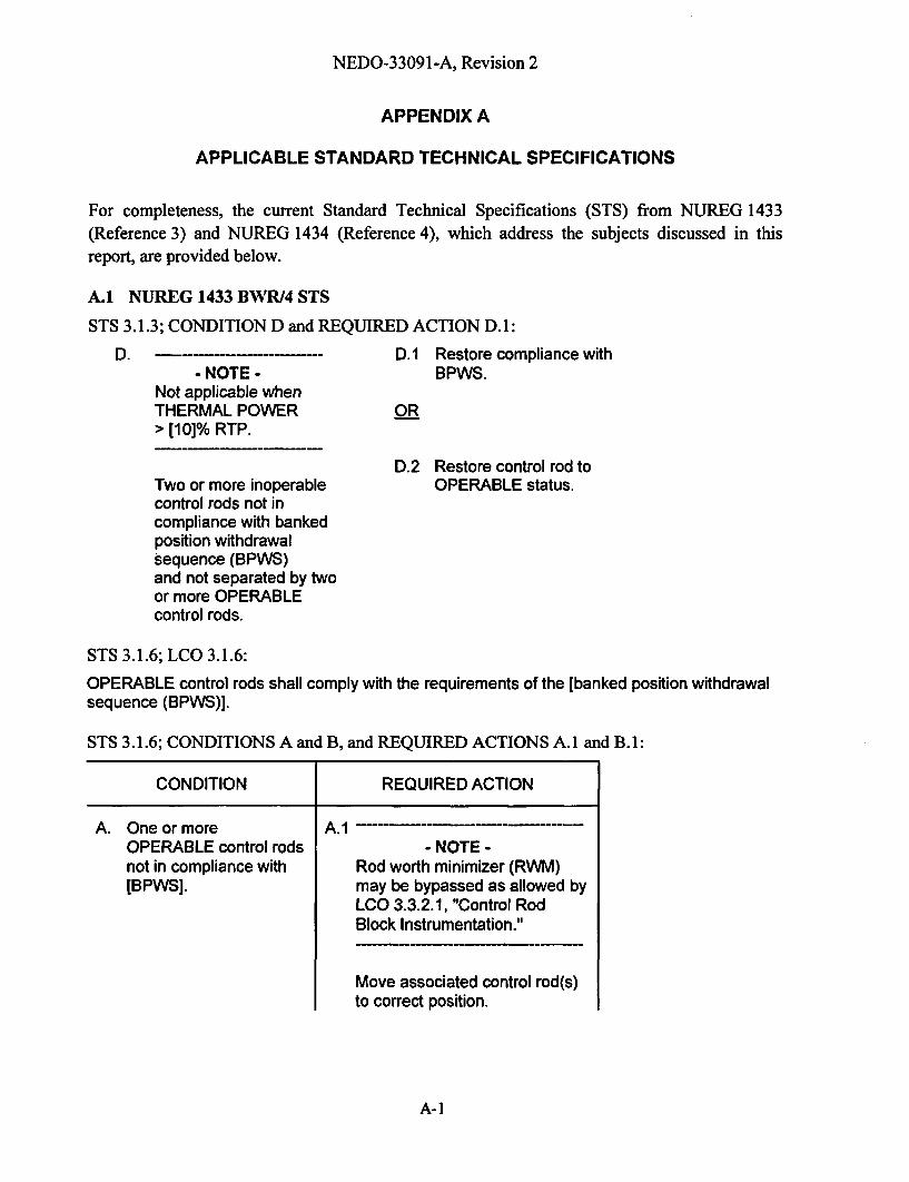
APPENDIX A
APPLICABLE STANDARD TECHNICAL SPECIFICATIONS
For completeness, the current Standard Technical Specifications (STS) from NUREG 1433(Reference 3) and NUREG 1434 (Reference 4), which address the subjects discussed in thisreport, are provided below.
A.1 NUREG 1433 BWR/4 STS
STS 3.1.3; CONDITION D and REQUIRED ACTION D.1:
D.- NOTE -
Not applicable whenTHERMAL POWER> [10]% RTP.
D.1 Restore compliance withBPWS.
OR
D.2 Restore control rod toOPERABLE status.Two or more inoperable
control rods not incompliance with bankedposition withdrawalsequence (BPWS)and not separated by twoor more OPERABLEcontrol rods.
STS 3.1.6; LCO 3.1.6:
OPERABLE control rods shall comply with the requirements of the [banked position withdrawalsequence (BPWS)].
STS 3.1.6; CONDITIONS A and B, and REQUIRED ACTIONS A.1 and B.1:
CONDITION | REQUIRED ACTION
A. One or moreOPERABLE control rodsnot in compliance with[BPWS].
A.1- NOTE -
Rod worth minimizer (RWM)may be bypassed as allowed byLCO 3.3.2.1, "Control RodBlock Instrumentation."
Move associated control rod(s)to correct position.
A-]
NEDO-33091 -A, Revision 2
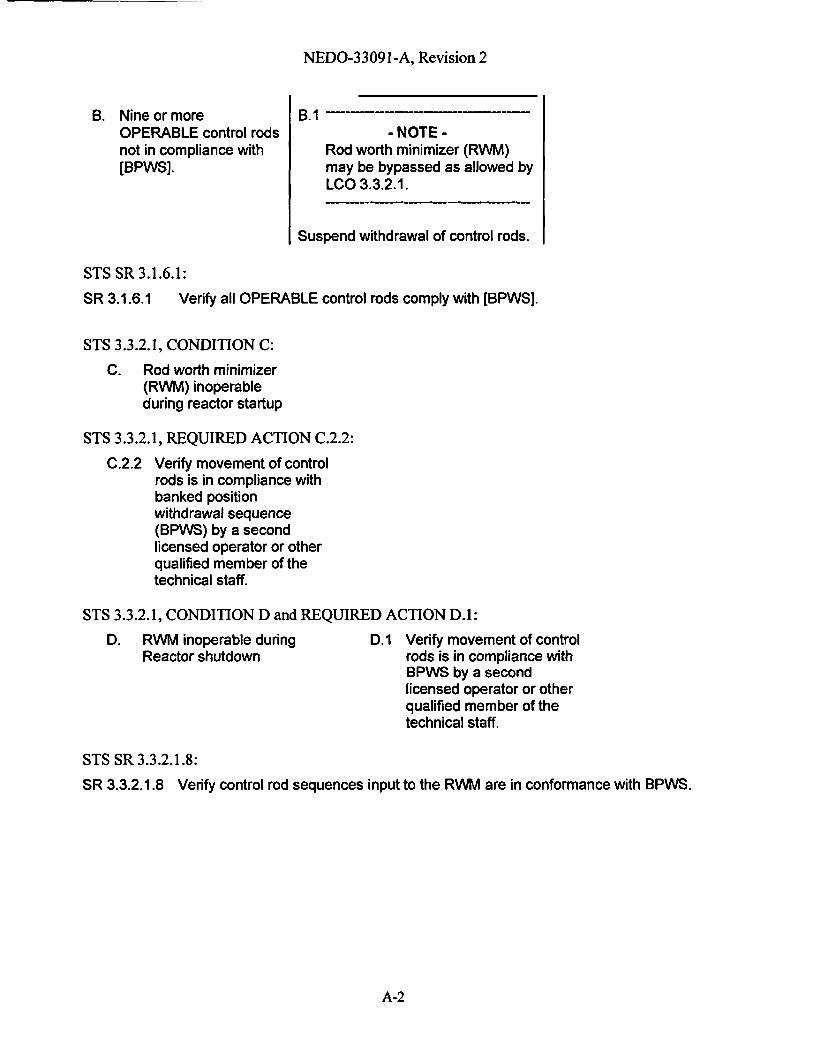
B. Nine or moreOPERABLE control rodsnot in compliance with[BPWS].
B.1- NOTE -
Rod worth minimizer (RWM)may be bypassed as allowed byLCO 3.3.2.1.
Suspend withdrawal of control rods.
STS SR 3.1.6.1:
SR 3.1.6.1 Verify all OPERABLE control rods comply with [BPWS].
STS 3.3.2.1, CONDITION C:
C. Rod worth minimizer(RWM) inoperableduring reactor startup
STS 3.3.2.1, REQUIRED ACTION C.2.2:
C.2.2 Verify movement of controlrods is in compliance withbanked positionwithdrawal sequence(BPWS) by a secondlicensed operator or otherqualified member of thetechnical staff.
STS 3.3.2.1, CONDITION D and REQUIRED ACTION D.1:
D. RWM inoperable duringReactor shutdown
D. I Verify movement of controlrods is in compliance withBPWS by a secondlicensed operator or otherqualified member of thetechnical staff.
STS SR 3.3.2.1.8:
SR 3.3.2.1.8 Verify control rod sequences input to the RWM are in conformance with BPWS.
A-2
NEDO-33091-A, Revision 2
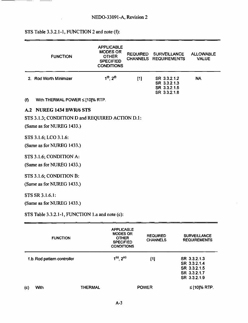
STS Table 3.3.2.1-1, FUNCTION 2 and note (f):
APPLICABLEMODES OR REQUIRED SURVEILLANCE ALLOWABLESPECIFIED CHANNELS REQUIREMENTS VALUE
CONDITIONS
2. Rod Worth Minimizer 1i", 2M [11 SR 3.3.2.1.2SR 3.3.2.1.3SR 3.3.2.1.5SR 3.3.2.1.8
NA
(f) With THERMAL POWER < [10]% RTP.
A.2 NUREG 1434 BWR/6 STS
STS 3.1.3; CONDITION D and REQUIRED ACTION D.1:
(Same as for NUREG 1433.)
STS 3.1.6; LCO 3.1.6:
(Same as for NUREG 1433.)
STS 3.1.6; CONDITION A:
(Same as for NUREG 1433.)
STS 3.1.6; CONDITION B:
(Same as for NUREG 1433.)
STS SR 3.1.6.1:
(Same as for NUREG 1433.)
STS Table 3.3.2.1-1, FUNCTION l.a and note (c):
APPLICABLEMODES OR REQUIRED SURVEILLANCE
FUNCTION SPECIFIED CHANNELS REQUIREMENTS
CONDITIONS
1.b. Rod pattern controller 1 (c) 2(c) [1 SRSRSRSRSR
3.3.2.1.33.3.2.1.43.3.2.1.53.3.2.1.73.3.2.1.9
(c) With THERMAL POWER < [10]% RTP.
A-3

NEDO-33091-A, Revision 2
APPENDIX B
NRC REQUESTS FOR ADDITIONAL INFORMATIONAND
ACCEPTED RESPONSES
B-i

GE Nuclear EnergyNuclear Services175 Curtner Ave. M/C 747San Jose, CA 95125(408) 925-1913, Fax (408) 925-6710E-mail: [email protected]
MFN 04-047April 21, 2004
U.S Nuclear Regulatory CommissionDocument Control DeskWashington, D.C. 20852-2738
Attention: Chief, Information Management BranchProgram ManagementPolicy Development and Analysis Staff
Subject: Responses to Informal NRC RAIs and Concerns From A 03/23/04 ConferenceCall Regarding The Improved BPWS, LTR NEDO-33091
During the NRC Staff review of the Reference 1 Licensing Topical Report (LTR), throughemails and a 03/23/04 GE-NRC conference call the NRC provided a number of informal requestsfor additional information (RAIs) and voiced some other concerns with respect to Reference 1.Enclosure 1 provides GE's responses to all of those RAIs and concerns.
If you have any questions, please contact, Kurt Schaefer at (408) 925-2426 or myself.
Sincerely,
George StrambackManager, Regulatory ServicesGE Nuclear Energy(408) 925-1913george.strambackggene.ge.com
Project No. 710
Reference:1. BWR Owners' Group Licensing Topical Report, Improved BPWS Control Rod Insertion
Process, NEDO-33091 (non-proprietary), April 2003.

MFN 04-047Page 2
Enclosures:
1. Responses to NRC Staff Requests For Additional Information on NEDO-33091.
cc: AB Wang (NRC)Bo Pham (NRC)J. Tuttle (GNF)DRF 0000-0026-2578

Responses to NRC Staff Requests For Additional Information On NEDO-33091
The LTR states that it is impossible for a control rod to become decoupled during theshutdown process following the improved BPWS. Please provide detailed informationabout the different types of control rod drives (CRDs) used for BWR-2 to BWR-6 plantswith respect to the coupling between the CRD and control rod during shut-down. Based on
this information, please also explain why it is not possible for the CRD and control rod tobe decoupled.
Response:All Reg. Guide 1.70, Rev.3 BWR UFSARs contain failure mode and effects analyses(FMEA) for the CRD system. Attachment 1 includes some pages from the FMEA in a
typical BWR UFSAR (i.e., Limerick). As stated in the last paragraph of page 4.6-18, nosingle failure can of itself initiate a rod withdrawal. This statement is even more
applicable, when the collet fingers are locked, such as when there is no CR movement orthe CR is being inserted. (See Limerick Figure 4.6-3.) For a CR to withdraw, the six colletfingers must be unlocked so that the index tube can be lowered without being latched to astop by the collet fingers. During CR insertion, if a mechanicallhydraulic failure occursthat stops all upward hydraulic force, the most the CR could withdraw is 6 inches to thenext index tube latching indentation.
As summarized in UFSAR subsection 4.6.2.3.1.4, a limiting multi-failure scenario with thecollet fingers remaining open has been evaluated. The resulting maximum CR withdrawalspeed is 2 ft/sec, which is bounded by the 5 ft/sec CR drop speed assumed in the ControlRod Drop Accident (CRDA) analyzed in UFSAR Chapter 15, as discussed in UFSARsubsection 4.6.2.3.2.2.
Attachment 1 also provides the UFSAR Control Rod Drive (CRD) and Control Rod (CR)design figures for a BWR/2 (Oyster Creek), BWR/3 (Monticello), BWR/4 (Limerick),BWR/5 (La Salle) and BWR/6 (Perry). For all BWR/2-6 plants, these figures demonstratethat a CR sits atop its associated CRD, and that it is physically impossible for a CR to movedown past (i.e., to be withdrawn) its CRD.
Normally, a CR cannot become uncoupled from its CRD, because the CRD spud ("6-fingers") mechanically locks into the CR socket, and operator action is required to unlockthis coupling. It is possible, due to a CRD assembly error, for a CRD to not properly lockinto CR. In this case, CR movement (withdrawal and insertion) and scram are notimpaired, because gravitational force will maintain the CR on top of its CRD. PlantTechnical Specifications already provide provisions for coupling checks and steps to betaken if a CR is uncoupled from its drive.
The improved BPWS only involves CR insertion steps that prevent the CRs from dropping(i.e., separating from CRD), and does not involve/affect any of the functions discussed
above.

Responses to NRC Staff Requests For Additional Information On NEDO-33091
2. In the GE Proprietary Information Class III document (WE-1048), which describes thecontrol rod drop design basis accident, page 6-16, Section 6.4, Control Rod Drop Accident,states the following:
"One of the four design basis accidents is a control rod drop. The design basis controlrod drop accident is defined as the complete (but unnecessarily sudden) rupture,breakage, or disconnection of a fully inserted control rod drive from its cruciformcontrol blade at or near the coupling and in such a way that the blade somehowbecomes stuck at its location inserted."
This description includes rupture and breakage as mechanisms that may trigger the roddrop accident (RDA). Please explain why the BWROG/GE changed from this definition tothe exclusion of CRD failure as one of the causes for RDA. Is the BWROG/GE proposinga new position that CRD failure will not be considered as the cause for RDA in futureanalyses?
Response:NEDO-33091 Rev. 2.0, "BWR Owners' Group Licensing Topical Report: Improved BPWSControl Rod Insertion Process", describes an improved control rod (CR) insertion process.The rod drop accident scenario, also described in the report (1.0 Background), requires thefollowing conditions:
1. The CR is not coupled to the control rod drive (CRD).
2. The CR is stuck.
3. The CRD is withdrawn, leaving the stuck CR suspended in position.
4. The CR subsequently becomes unstuck and drops freely at 3.1 feet/second.
Because the Improved BPWS process, described by NEDO-33091, is only for CR insertionand does not involve CR withdraw, then one of the primary factors in the rod drop accident(item 3, above) is eliminated. Therefore, the rod drop accident scenario is eliminated fromconsideration for this CR insertion process.
Additionally, there are no single failure scenarios that will result in a CRwithdrawal/ejection/drop, including CRD withdrawals with CR velocities corresponding tothe control rod drop accident. "There are no known single malfunctions that cause theunplanned (i.e., no operator action is involved) withdrawal of even a single control rod."[See (in Attachment 2) Limerick UFSAR 4.6.2.3.2.2 for BWR/2-5 CRDs and River BendUFSAR 4.6.2.3.2.2 for BWR/6 CRDs.] This applies to both BWR 2-5 CRDs and BWR/6CRDs, because they are essentially same regarding the design of the locking mechanismand the mechanism for CRD insertion, withrawal and scram. (The primary differencebetween these CRDs is the mechanism for slowing the control rod at the end of a scramstroke.) The scenarios, which result in CR withdrawal, require multiple failures combinedwith a CR withdrawal signal (not part of the improved CR insertion process). Otherwise,the CRD latching mechanism, the hydraulic conditions and/or the control rod drive housingsupport prevent CR withdrawal. [See (in Attachment 2) Limerick UFSAR 4.6.2.3.2.2.1through 4.6.2.3.2.2.12 and River Bend UFSAR 4.6.2.3.2.2.1 through 4.6.2.3.2.2.12 forBWR/6 CRDs.]
Responses to NRC Staff Requests For Additional Information On NEDO-33091
For example, if the drive housing fails at the attachment weld (River Bend UFSAR4.6.2.3.2.2.1), "the CRD and housing would be blown downward against the supportstructure" and "if the collet were to remain latched" (which is expected in this scenario),"no further control rod ejection would occur." Also, the "maximum deflection isapproximately 3 in." If the "failure were to occur while the control rod is being withdrawn"(i.e., during a planned withdrawal) and "if the collet were to stay unlatched", then "thesteady-state rod withdrawal velocity would be 0.3 ft/sec" and would continue "until drivingpressure was removed from the pressure-over port" (i.e., the single notch out sequencestops automatically or the operator terminates the continuous withdraw command). Notethat unlike the latter scenario, the improved BPWS CR insertion process does not initiate aCR withdrawal command.
Regardless of the scenario, all CRD failure modes and effects evaluations in the UFSARsare unaffected by the Improved BPWS, which only involves CR insertion changes.

Responses to NRC Staff Requests For Additional Information On NEDO-33091
3. The improved BPWS will significantly reduce the time of the normal shut down process.The LTR states that the total rod manipulation steps for shutting down a medium sizedreactor will be reduced from approximately 400 to 150 steps. While this reduction allowsfor faster insertion of negative reactivity, the rapid power decrease may cause quenching ofthe reactor pressure vessel or the necessary speeding up of other processes. Please providea discussion about the impact of the improved BPWS on other procedures in this regard, ifany. In particular, please address how the reactor vessel Pressure-Temperature limit will bemaintained during the shut down process.
Response:The improved BPWS does not adversely (if at all) affect any normal shutdown process,including maintaining the reactor vessel cool down time rate within its Pressure-Temperature limits. Current operating procedures already account for the effects of themost limiting (fastest negative reactivity) CR insertion scenario, i.e., scram. Operationscontrol the cool down process by controlling reactor dome pressure, coolant flow andcoolant temperature, regardless of the CR insertion process.

Responses to NRC Staff Requests For Additional Information On NEDO-33091
4. Using the improved BPWS process, control rods not confirmed to be coupled are requiredto be fully inserted prior to reducing power below the low power set point (LPSP). Howdoes the improved BPWS ensure this full insertion prior to the LPSP? Is it possible forsome of the un-confirmed rods to not be fully inserted with power dropping below theLPSP?
Response:As with the original BPWS, the insertion steps are controlled by plant procedures, and thus,to implement the improved BPWS, plant procedures will be updated. Section 5, Item A ofthe LTR provides guidance to be used in updating plant procedures, to ensure that any un-confirmed CR are fully inserted prior to reaching the LPSP. The probability of an un-confirmed rod not being fully inserted, while the power drops below the LPSP, is remotebecause of the followings:
a. The LTR requires that each CR that has not been confirmed coupled (since its lastwithdrawal) to be fully inserted prior to reducing power below the LPSP. Therefore,the operator is aware of the status of each rod.
b. The control rods are inserted, as much as reasonably possible, in the same order asspecified for the standard BPWS. Therefore, the operator is absolutely aware of thestatus of each control rod before the shutdown process begins.
c. The LTR states that operations shall confirm control rod coupling integrity for all rodsthat are fully withdrawn and there would be two documented coupling checks or oneverified and documented coupling check. Therefore, the probability of not confirmingthe coupling integrity of the fully withdrawn rod is remote.
For normal shutdowns, it is expected that all potentially un-confirmed CRs will be insertedprior to reducing power to 40%, which is significantly above the LPSP. However, the lastparagraph in LTR page 5-1 addresses the postulated scenario of a plant being below LPSPprior to having all un-confirmed CRs fully inserted. The LTR states, "If shutdown isrequired and all rods, which are not confirmed coupled, cannot be fully inserted prior tothe power dropping below the LPSP (such as shortly after a startup), then the standard(e.g., Reference 2) BPWS must be observed below the LPSP or a scram is requiredHowever, during the shutdown process using the standard BPWS and after all rods, whichwere not confirmed coupled, have been fully inserted, the improved BPWS control rodinsertion process may be used."
Therefore, the improved BPWS is only allowed to be used when all un-confirmed CRs arefully inserted prior to power dropping below the LPSP.

Responses to NRC Staff Requests For Additional Information On NEDO-33091
5. Page 2-1 of the LTR states, "require control rod confirmations....." Does this requirementapply to all control rods? If not, please clarify which control rods need to be confirmed.
Response:Currently, plant Technical Specifications require all CRs to be coupled to their CRDs.Technical Specifications Surveillances require coupling checks (a) prior to reactorcriticality after completing core alterations, (b) anytime a CR is withdrawn to the full outposition, and (3) following maintenance on or modification to a CR or CRD system. Theserequirements are not affected by the improved BPWS.
LTR Section 5 Item A discusses how the improved BPWS goes beyond the aboverequirements. To avoid a single operator error (SOE), rod couplings must be checkedtwice or be verified by a second operator. This applies to all CRs that are not already fullyinserted.
Responses to NRC Staff Requests For Additional Information On NEDO-33091
6. Will the improved BPWS replace all existing BPWSs in U.S. BWRs? Will there be anyexceptions?
Response:The improved BPWS does not replace the existing BPWS. The improved BPWS onlyprovides an alternate approach to the existing BPWS with respect to control rod insertions,when a plant is being shutdown and all non-fully inserted control rods have been confirmedto be coupled. The improved BPWS may be used by all U.S. BWRs, but it is notmandatory. The implementation of the improved BPWS is a plant-specific decision.

Responses to NRC Staff Requests For Additional Information On NEDO-33091
Addressing NRC Concerns From the 3/23/05 Conference Call &Clarification of the Response to Improved BPWS LTR RAI 1.1
1. Explanation of the difference between the velocities stated in UFSAR 4.6.2.3.1.4 (2 fps)and 4.6.2.3.2.2.7 (11.8 fps).
The velocity stated in 4.6.2.3.1.4 (2 fps) is the result of the scenario described in 4.6.2.3.2.2.2.1Pressure-Under (Insert) Line Break. In this scenario, failure of the insert line occurs while therod is being withdrawn. The flange ball check valve would lift and close the flow path outthrough the failed insert line due to the differential pressure. Then the under-piston water (whileCRD is withdrawing) would be routed to the flange vessel ports (under the ball check valve) anddischarged into the reactor vessel. Because the hydraulic resistance of this flow path is less thanthe normal resistance through the Directional Control Valve (i.e., a throttled valve), the velocityincreases to 2 fps if the collet is stuck open (in the unlatched position). Normally, at this velocity(2 fps) the hydraulic force would not be sufficient to hold the collet open and the collet would beforced into the latched position, hence, stopping rod withdrawal. In summary, the operatorselects this rod for withdrawal and two failures are assumed: failed insert line and collet failureto latch during the higher than normal velocity condition.
The velocity stated in 4.6.2.3.2.2.7 (11.8 fps) is the result of the failure of the flange ball checkvalve plug while the rod is being withdrawn. The under-piston water (while CRD iswithdrawing) would be discharged through the hole in the side of the flange and directly out toatmosphere. Because the hydraulic resistance of this flow path is significantly less than thenormal resistance through the Directional Control Valve (i.e., a throttled valve) or through theflange vessel ports (mentioned above), the velocity increases to 11+ fps if the collet is stuckopen. Normally, at this high velocity the hydraulic force would not be sufficient to hold thecollet open and the collet would be forced into the latched position, hence, stopping rodwithdrawal. In summary, the operator selects this rod for withdrawal and two failures areassumed: failed flange ball check valve plug and collet failure to latch during the higher thannormal velocity condition.
2. Explanation of the failure scenario described in 4.6.2.3.2.2.11 relative to single failure.
Two cases could lead to continuous rod withdrawal following a deliberate withdrawal command.
Case 1: Following a withdrawal command and assuming the signal terminates as expected, afailure of the Directional Control Valve to close would cause the rod to continue to withdraw.
Case 2: Following a withdrawal command and assuming the signal terminates as expected, afailure of the collet to return to its latched position would cause the rod to continue to drift out.
Yes, a single failure (failure of Directional Control Valve to close or failure of the collet to returnto its latched position) would cause the rod to continuously drift out. In summary, an inadvertentcontinuous rod withdrawal must be first initiated by the operator's withdrawal commandfollowed by one of these failures.
3. Explanation of the statement "unplanned withdrawal" in 4.6.2.3.2.2.
In the 4.6.2.3.2.2 statement "There are no known single malfunctions that cause the unplannedwithdrawal of even a single control rod," an "unplanned withdrawal" is a CR withdrawal thatdoes not involve any operator action, e.g., the operator does not initiate a CR withdrawal.

Responses to NRC Staff Requests For Additional Information On NEDO-33091
RAI 1.1 has been renumbered as RAI 2, above. The response to RAI 2, above, is the clarifiedresponse to RAI 1.1.

Responses to NRC Staff Requests For Additional Information On NEDO-33091
Attachment 1
UFSAR CRD FMEA and CRD & CR UFSAR Design Figures for BWR/2 - 6
LGS UFSAR
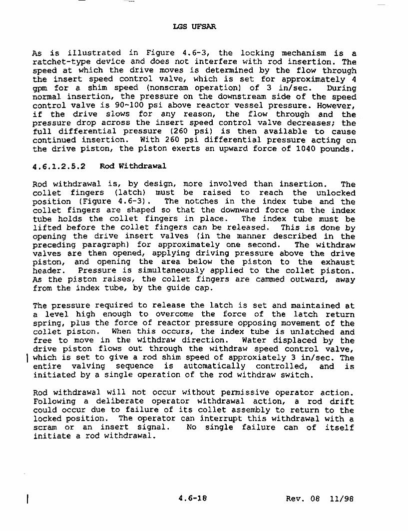
As is illustrated in Figure 4.6-3, the locking mechanism is aratchet-type device and does not interfere with rod insertion. Thespeed at which the drive moves is determined by the flow throughthe insert speed control valve, which is set for approximately 4gpm for a shim speed (nonscram operation) of 3 in/sec. Duringnormal insertion, the pressure on the downstream side of the speedcontrol valve is 90-100 psi above reactor vessel pressure. However,if the drive slows for any reason, the flow through and thepressure drop across the insert speed control valve decreases; thefull differential pressure (260 psi) is then available to causecontinued insertion. With 260 psi differential pressure acting onthe drive piston, the piston exerts an upward force of 1040 pounds.
4.6.1.2.5.2 Rod Withdrawal
Rod withdrawal is, by design, more involved than insertion. Thecollet fingers (latch) must be raised to reach the unlockedposition (Figure 4.6-3). The notches in the index tube and thecollet fingers are shaped so that the downward force on the indextube holds the collet fingers in place. The index tube must belifted before the collet fingers can be released. This is done byopening the drive insert valves (in the manner described in thepreceding paragraph) for approximately one second. The withdrawvalves are then opened, applying driving pressure above the drivepiston, and opening the area below the piston to the exhaustheader. Pressure is simultaneously applied to the collet piston.As the piston raises, the collet fingers are cammed outward, awayfrom the index tube, by the guide cap.
The pressure required to release the latch is set and maintained ata level high enough to overcome the force of the latch returnspring, plus the force of reactor pressure opposing movement of thecollet piston. When this occurs, the index tube is unlatched andfree to move in the withdraw direction. Water displaced by thedrive piston flows out through the withdraw speed control valve,which is set to give a rod shim speed of approxiately 3 in/sec. Theentire valving sequence is automatically controlled, and isinitiated by a single operation of the rod withdraw switch.
Rod withdrawal will not occur without permissive operator action.Following a deliberate operator withdrawal action, a rod driftcould occur due to failure of its collet assembly to return to thelocked position. The operator can interrupt this withdrawal with ascram or an insert signal. No single failure can of itselfinitiate a rod withdrawal.
I 4.6-18 Rev. 08 11/98
LGS UrSAR
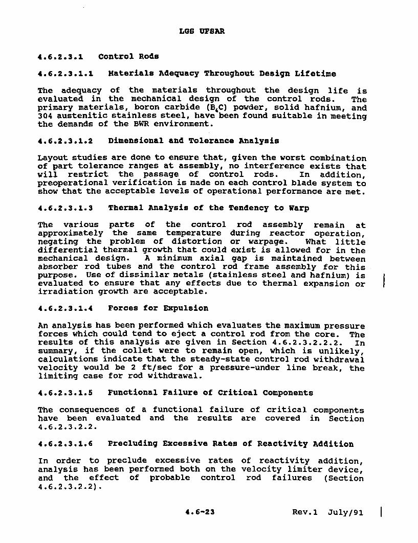
4.6.2.3.1 Control Rods
4.6.2.3.1.1 Materials Adequacy Throughout Design Lifetime
The adequacy of the materials throughout the design life isevaluated in the mechanical design of the control rods. Theprimary materials, boron carbide (B.C) powder, solid hafnium, and304 austenitic stainless steel, have been found suitable in meetingthe demands of the BWR environment.
4.6.2.3.1.2 Dimensional and Tolerance Analysis
Layout studies are done to ensure that, given the worst combinationof part tolerance ranges at assembly, no interference exists thatwill restrict the passage of control rods. In addition,preoperational verification is made on each control blade system toshow that the acceptable levels of operational performance are met.
4.6.2.3.1.3 Thermal Analysis of the Tendency to Warp
The various parts of the control rod assembly remain atapproximately the same temperature during reactor operation,negating the problem of distortion or warpage. What littledifferential thermal growth that could exist is allowed for in themechanical design. A minimum axial gap is maintained betweenabsorber rod tubes and the control rod frame assembly for thispurpose. Use of dissimilar metals (stainless steel and hafnium) isevaluated to ensure that any effects due to thermal expansion orirradiation growth are acceptable.
4.6.2.3.1.4 Forces for Expulsion
An analysis has been performed which evaluates the maximum pressureforces which could tend to eject a control rod from the core. Theresults of this analysis are given in Section 4.6.2.3.2.2.2. Insummary, if the collet were to remain open, which is unlikely,calculations indicate that the steady-state control rod withdrawalvelocity would be 2 ft/sec for a pressure-under line break, thelimiting case for rod withdrawal.
4.6.2.3.1.5 Functional Failure of Critical Components
The consequences of a functional failure of critical componentshave been evaluated and the results are covered in Section4.6.2.3.2.2.
4.6.2.3.1.6 Precluding Excessive Rates of Reactivity Addition
In order to preclude excessive rates of reactivity addition,analysis has been performed both on the velocity limiter device,and the effect of probable control rod failures (Section4.6.2.3.2.2).
4.6-23 Rev.l July/91 I

LGS UFSAR
4.6.2.3.2 Control Rod Drives
4.6.2.3.2.1 Evaluation of Scram Time
The rod scram function of the CRD system provides the negativereactivity insertion required by safety design basis as stated inSection 4.6.1.1.1. The scram time shown in the description isadequate as shown by the transient analyses of Chapter 15.
4.6.2.3.2.2 Analysis of Malfunction Relating to Rod Withdrawal
There are no known single malfunctions that cause the unplannedwithdrawal of even a single control rod. However, if multiplemalfunctions are postulated, studies show that an unplanned rodwithdrawal can occur at withdrawal speeds that vary with thecombination of malfunctions postulated. In all cases thesubsequent withdrawal speeds are less than that assumed in the rod-drop accident analysis as discussed in Chapter 15. Therefore, thephysical and radiological consequences of such rod withdrawals areless than those analyzed in the rod-drop accident.
4.6.2.3.2.2.1 Drive Housing Failure at Attachment Weld
The bottom head of the reactor vessel has a penetration for eachCRD location. A drive housing is raised into position inside eachpenetration and is fastened by welding. The drive is raised intothe drive housing and bolted to a flange at the bottom of thehousing. The housing material is seamless, Type 304 stainlesssteel pipe with a minimum tensile strength of 75,000 psi. Thebasic failure considered here is a complete circumferential crackthrough the housing wall at an elevation just below the J-weld.
Static loads on the housing wall include the weight of the driveand the control rod, the weight of the housing below the J-weld,and the reactor pressure acting on the 6 inch diameter cross-sectional area of the housing and the drive. Dynamic loadingresults from the reaction force during drive operation.
If the housing were to fail as described, the following sequenceof events is foreseen:
a. The housing would separate from the reactor vessel.
b. The CRD and housing would be blown downward against thesupport structure, by reactor pressure acting on thecross-sectional area of the housing and the drive.
4.6-25

utsm USM
OALL CVAIL
REACTOR PRE
WrTrAW UNE
ARM=W V40W WATZXrLoW Wax.l THAc o CRIrSin
OPEtRATICN.
GPU NUCLEAR CORPORATIONOYSTER CREEK NUCLEAR GENERATING STATION
UPDATEDFINAL SAFETY ANALYSIS REPORT
CONTROL ROD DRIVE-CUTAWAY
REV. 0, 12/84 I FIGUjRE A 9La I FIGtJRF�.�

CONTROLRODASSEMBLYwNELOCITY LIMITER
UNLOCKINGHANDLE
I UNLOCKING TUBE
ACTUATING SHAFT
SOCKET(LOCK PLUG)RETURN
GPU NUCLEAR CORPORATIONOYSTER CREEK NUCLEAR GENERATING STATION
UPDATEDFINAL SAFETY ANALYSIS REPORT
I_
CONTROL ROD TO DRIVE COUPLINGISOMETRIC
REV. 0, 12/84 I FIGURE 4.6-4REV. 0, 12/84 I FlGIJRE 4.64I
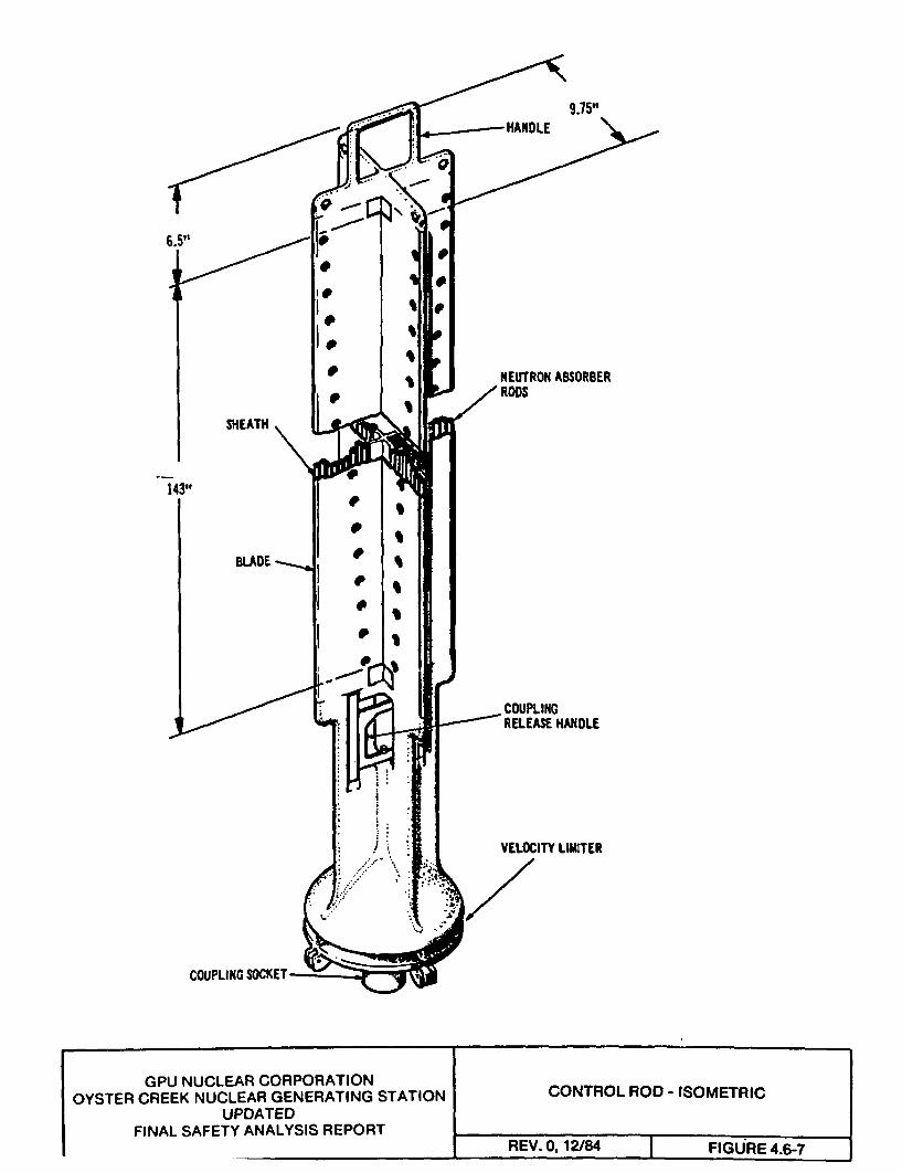
9.75,
SHEATH
143"
BLADE
NEUTRON ABSORBER' RODS
- COUPLINGRELEASE HANDLE
VELOCITY LIMITER
COUPLING SOCKET-
I
GPU NUCLEAR CORPORATIONOYSTER CREEK NUCLEAR GENERATING STATION
UPDATEDFINAL SAFETY ANALYSIS REPORT
CONTROL ROD - ISOMETRIC
REV. 0. 12/84 I FIGURE 4.6-7REV. 0, 12V84 I FIGURE 4.6-7

MONTICELLO UPDATED SAFETY ANALYSIS REPORT USAR &.FIGURESRevision 20Page 10 of 19
Figure 3.5-1 Control Rod Assembly Isometric
HANDLE
-NEUTRON ABSORBERRODS
-COUPLING RELEASEHANDLE
.--VELOCITY LIMITER
COUPLING SOCKE B.1.1-O6.02-3
IA mr

MONTICELLO UPDATED S1^ A P_-V A li2A X VJ^XeW t - 15nt
SAtFtZY ANALTY bibrt it USAR 3.FIGURESRevision 20Page 11 of 10
Figure 3.5-1a Duralife - 230 Control Blade
UPPER HANOLE
0
000
0WF ARSM0R
0 0 NEUTRON &SSORSEPO% O FNIU STRIP
SHE w q
00
0
COUPLING RELEASEHANOLE ILOWEAI V C MTER
COuPliN SOCKET
l/fmr
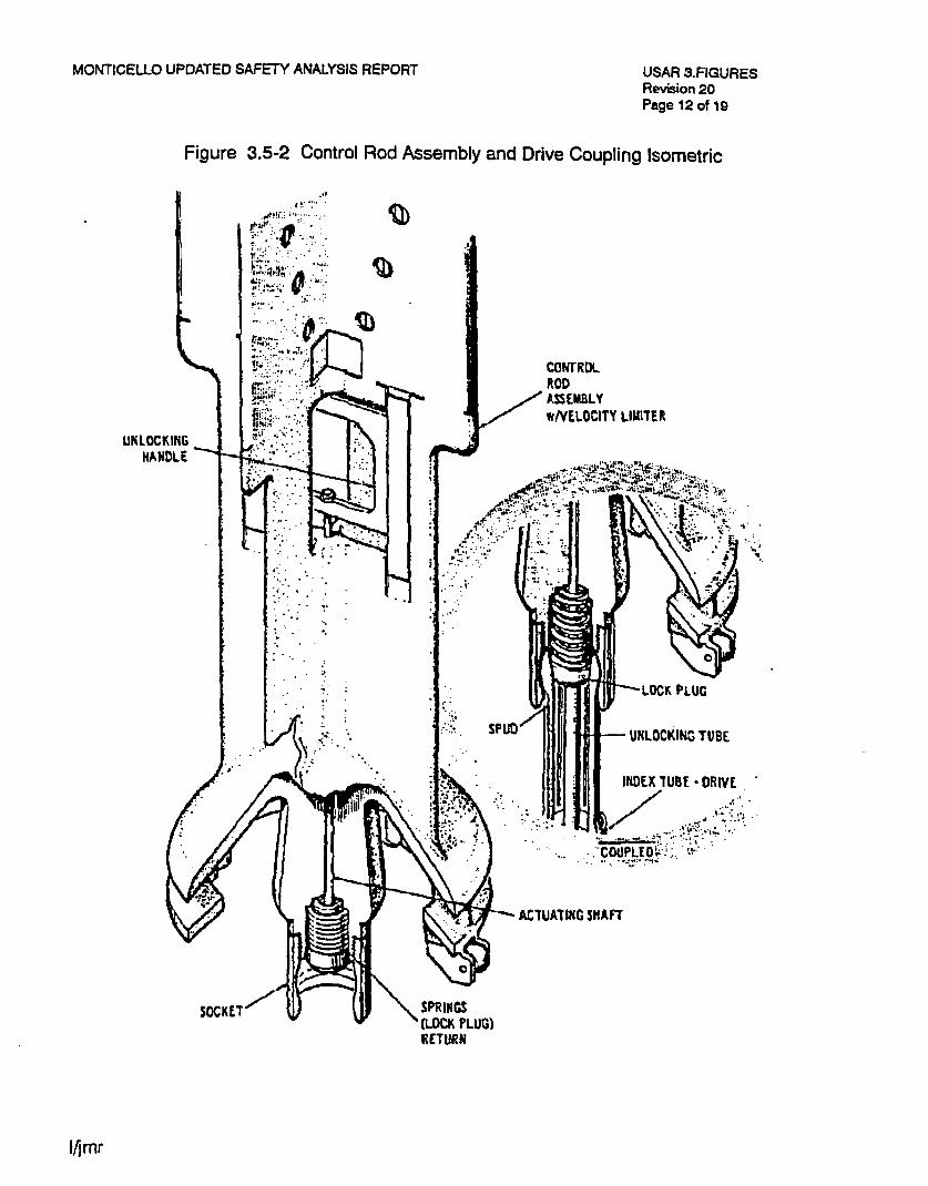
MONTHCELLO UPDATED SAFETY ANALYSIS REPORT USAR 3.FIGURESRevision 20Page 12 of 19
Figure 3.5-2 Control Rod Assembly and Drive Coupling Isometric
o..
.f . .... . CONTROLROD
Z .ASSEMELYwNELOCITY LIItrTER
UNLOCKINGHANDLE
SPRINGS'(LOCKt PLUG)
RETURN
I/jmr

UNLOCKING HANDLE(SHOWN RAISED
AGAINST SPRING FORCEI
VELOCITYLIMITER
- DRIVE
LIMERICK GENERATING STATIONUNITS 1 AND 2
UPDATED FINAL SAFETY ANALYSIS REPORT
CONTROL ROD TO CONTROLROD DRIVE COUPLING
FIGURE 4.6-1

DRIVE INSERT LINE DRIVE WITHDRAWA LINE
ARROWS SHOW WATER FLOWWHEN THE DRIVE IS IN THEWITHDRAWAL MODE OFOPERATION.
PR = REACTOR PRESSURE
LIMERICK GENERATING STATIONUNITS 1 AND 2
UPDATED FINAL SAFETY ANALYSIS REPORT
CONTROL ROD DRIVE UNIT
FIGURE 4.6-2

LIMERICK GENERATING STATIONUNITS 1 AND 2
UPDATED FINAL SAFETY ANALYSIS REPORT
CONTROL ROD DRIVE SCHEMATICBWR/4 & 5
FIGURE 4.6-3
UNLOCKING HANDLE(SHOWN RAISEDAGAINST SPRING FOI
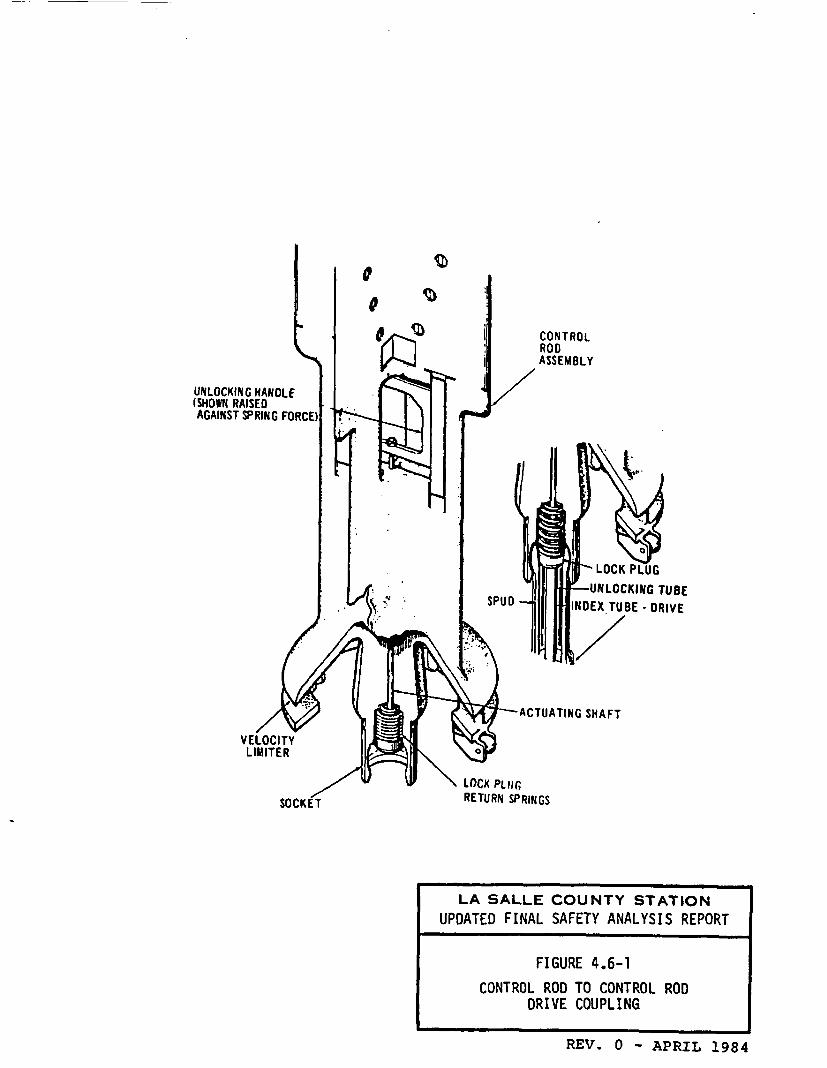
LA SALLE COUNTY STATIONUPDATED FINAL SAFETY ANALYSIS REPORT
FIGURE 4.6-1
CONTROL ROD TO CONTROL RODDRIVE COUPLING
REV. 0 - APRIL 1984
DRIVE 111i11ORAW
amv( 111(3? tint LIKE
IfilOls SHOW WATER VI'E WHEN
THE DRIVE ISIN1 THE litHORANAL
ioot or OFOtAm.
BAVL CHECK PRLSUR ES SHO0I ARE MAXIMU.
VALFe P. REACTOR PRESSURE
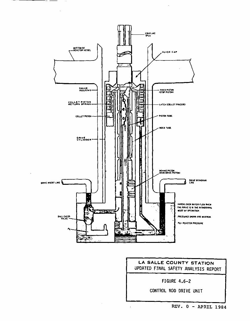
LA SALLE COUNTY STATIONUPDATED FINAL SAFETY ANALYSIS REPORT
FIGURE 4.6-2
CONTROL ROD DRIVE UNIT
REV. 0 - APRIL 1984

NOTE: A CIRCLED NUMBERINDICATES A PRESSUREPOINT.
SPRING -WASHERS
BUFFER -
HOLES
PRESSUREOVER PORT
NUUSINGFLANGE
PISTON TUBE TO PISTON JTUBE HEAD WELD
RING FLANGE SOLT-
POSITION INDICATOR WELL.TO PISTON TUBE HEAD WELD
LA SALLE COUNTY STATIONUPDATED FINAL SAFETY ANALYSIS REPORT
FIGURE 4.6-3
CONTROL ROD DRIVE UNIT (SCHEMATIC)
REV. 0 - APRIL 1984

UNLOCKING HANDLE(SHOWN RAISED
AGAINST SPRING FORCE)
VELOCITYLIM ITER
TUBE - DRIVE
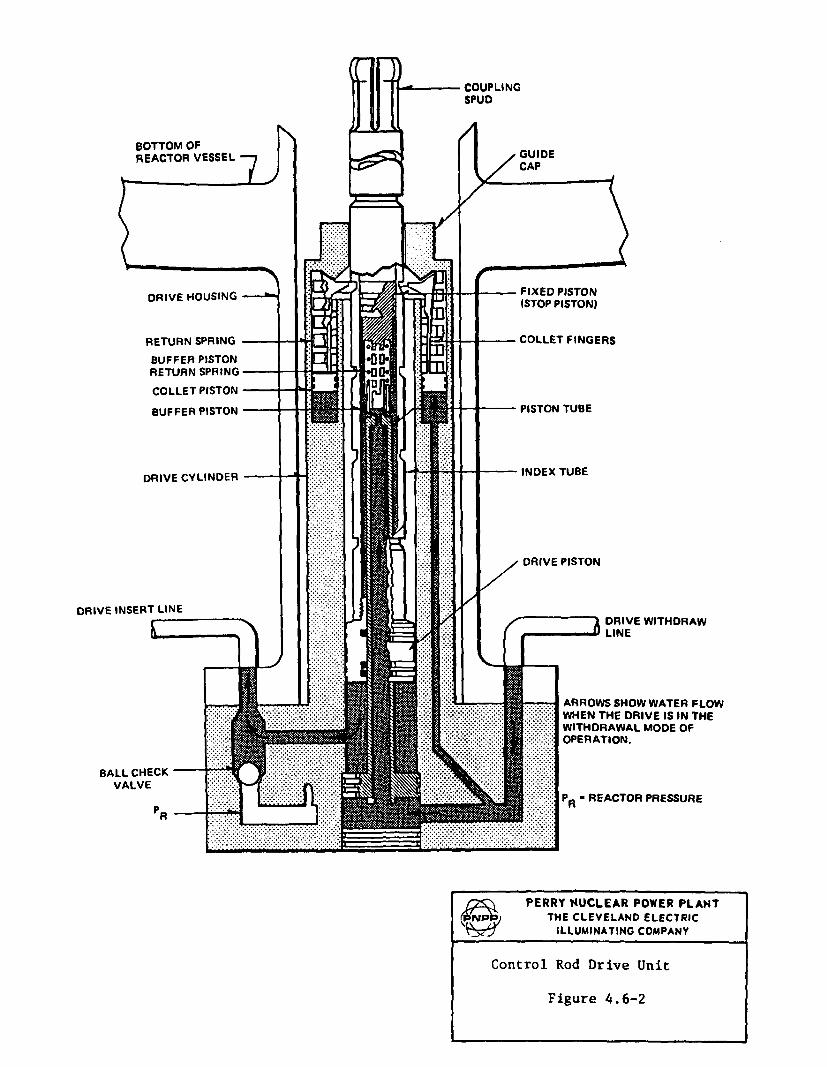
i 9I' PERRY NUCLEAR POWER PLANT,Pap THE CLEVELAND ELECTRIC
In ILLUMINATING COMPANY
Control Rod to Control Rod DriveCoupling
Figure 4.6-1
DRIVE INSERT LINE
L 7ADRIVE WITHDRAWLINE
ARROWS SHOW WATER FLOWWHEN THE DRIVE IS IN THEWITHDRAWAL MODE OFOPERATION.
= REACTOR PRESSURE
PERRY NUCLEAR POWER PLANTPNPf THE CLEVELAND ELECTRIC
ILLUMINATING COMPANY
Control Rod Drive Unit
Figure 4.6-2

-COLLET FINGERS1
- COLLET SPRING COLLET
- COLLET-PISTONAND RINGS
- HOUSING TO FLANGE WELD
-FLANGEHUB
-PRESSUREUNDER PORT
-BALL CHECK VALVECAGE
-WELDEDPLUG
-WELDEDPLUG
- MAINPLANGE BOLTS
-POSITION-INDICATOR WELL
POSITION INDICATORHOUSING
/PERRY NUCLEAR POWER PLANT9 )NP THE CLEVELAND ELECTRIC
_j ILLUMINATING COMPANY
Control Rod Drive Schematic
Figure 4.6-3

Responses to NRC Staff Requests For Additional Information On NEDO-33091
Attachment 2
UFSAR Pages Related to the Response to RAI 2

LGS UFSAR
4.6.2.3.2 Control Rod Drives
4.6.2.3.2.1 Evaluation of Scram Time
The rod scram function of the CRD system provides the negativereactivity insertion required by safety design basis as stated inSection 4.6.1.1.1. The scram time shown in the description isadequate as shown by the transient analyses of Chapter 15.
4.6.2.3.2.2 Analysis of Malfunction Relating to Rod Withdrawal
There are no known single malfunctions that cause the unplannedwithdrawal of even a single control rod. However, if multiplemalfunctions are postulated, studies show that an unplanned rodwithdrawal can occur at withdrawal speeds that vary with thecombination of malfunctions postulated. In all cases thesubsequent withdrawal speeds are less than that assumed in the rod-drop accident analysis as discussed in Chapter 15. Therefore, thephysical and radiological consequences of such rod withdrawals areless than those analyzed in the rod-drop accident.
4.6.2.3.2.2.1 Drive Housing Failure at Attachment Weld
The bottom head of the reactor vessel has a penetration for eachCRD location. A drive housing is raised into position inside eachpenetration and is fastened by welding. The drive is raised intothe drive housing and bolted to a flange at the bottom of thehousing. The housing material is seamless, Type 304 stainlesssteel pipe with a minimum tensile strength of 75,000 psi. Thebasic failure considered here is a complete circumferential crackthrough the housing wall at an elevation just below the J-weld.
Static loads on the housing wall include the weight of the driveand the control rod, the weight of the housing below the J-weld,and the reactor pressure acting on the 6 inch diameter cross-sectional area of the housing and the drive. Dynamic loadingresults from the reaction force during drive operation.
If the housing were to fail as described, the following sequenceof events is foreseen:
a. The housing would separate from the reactor vessel.
b. The CRD and housing would be blown downward against thesupport structure, by reactor pressure acting on thecross-sectional area of the housing and the drive.
4.6-25
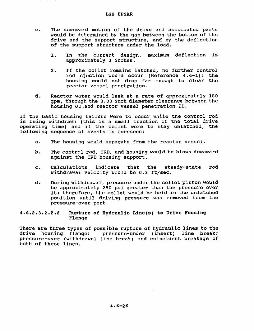
LGS UFSAR
c. The downward motion of the drive and associated partswould be determined by the gap between the bottom of thedrive and the support structure, and by the deflectionof the support structure under the load.
1. In the current design, maximum deflection isapproximately 3 inches.
2. If the collet remains latched, no further controlrod ejection would occur (Reference 4.6-1); thehousing would not drop far enough to clear thereactor vessel penetration.
d. Reactor water would leak at a rate of approximately 180gpm, through the 0.03 inch diameter clearance between thehousing OD and reactor vessel penetration ID.
If the basic housing failure were to occur while the control rodis being withdrawn (this is a small fraction of the total driveoperating time) and if the collet were to stay unlatched, thefollowing sequence of events is foreseen:
a. The housing would separate from the reactor vessel.
b. The control rod, CRD, and housing would be blown downwardagainst the CRD housing support.
c. Calculations indicate that the steady-state rodwithdrawal velocity would be 0.3 ft/sec.
d. During withdrawal, pressure under the collet piston wouldbe approximately 250 psi greater than the pressure overit; therefore, the collet would be held in the unlatchedposition until driving pressure was removed from thepressure-over port.
4.6.2.3.2.2.2 Rupture of Hydraulic Line(s) to Drive HousingFlange
There are three types of possible rupture of hydraulic lines to thedrive housing flange: pressure-under (insert) line break;pressure-over (withdrawn) line break; and coincident breakage ofboth of these lines.
4.6-26

LGS UFSAR
4.6.2.3.2.2.2.1 Pressure-Under (Insert) Line Break
For the case of a pressure-under (insert) line break, a partial orcomplete circumferential opening is postulated at or near the pointwhere the line enters the housing flange. Failure is more likelyto occur after another basic failure, wherein the drive housing orhousing flange separates from the reactor vessel. Failure of thehousing, however, does not necessarily lead directly to failure ofthe hydraulic lines.
If the pressure-under (insert) line were to fail and if the colletwere latched, no control rod withdrawal would occur. There would beno pressure differential across the collet piston and, therefore,no tendency to unlatch the collet. Consequently, the associatedcontrol rod could not be withdrawn, but if reactor pressure isgreater than 600 psig, it will insert on a scram signal.
The ball check valve is designed to seal off a brokenpressure-under line by using reactor pressure to shift the checkball to its upper seat. If the ball check valve were preventedfrom seating, reactor water would leak to the reactor enclosure orcontainment. Because of the broken line, cooling water could notbe supplied to the drive involved. Loss of cooling water wouldcause no immediate damage to the drive. However, prolongedexposure of the drive to temperatures at or near reactortemperature could lead to deterioration of material in the seals.High temperature would be indicated to the operator by thethermocouple in the position indicator probe, by high cooling waterflow, and by operation of the containment sump pump.
If the basic line failure were to occur while the control rod isbeing withdrawn, the hydraulic force would not be sufficient tohold the collet open, and spring force normally would cause thecollet to latch and stop rod withdrawal. However, if the colletwere to remain open, calculations indicate that the steady-statecontrol rod withdrawal velocity would be 2 ft/sec.
4.6.2.3.2.2.2.2 Pressure-Over (Withdrawn) Line Break
The case of the pressure-over (withdrawn) line breakage considersthe complete breakage of the line at or near the point where itenters the housing flange. If the line were to break, pressureover the drive piston would drop from reactor pressure toatmospheric pressure. Any significant reactor pressure(approximately 600 psig or greater) would act on the bottom of thedrive piston and fully insert the drive. Insertion would occurregardless of the operational mode at the time of the failure.After full insertion, reactor water would leak past the stop piston
4.6-27

LGS UFSAR
seals. This leakage would exhaust to the atmosphere through thebroken pressure-over line. The leakage rate at 1000 psi reactorpressure is estimated to be 1-3 gpm; however, with the Graphitarseals of the stop piston removed, the leakage rate could be as highas 10 gpm, based on experimental measurements. If the reactor werehot, drive temperature would increase. This situation would beindicated to the reactor operator by the drift alarm, by the fullyinserted drive, by a high drive temperature (annunciated in thecontrol room), and by operation of the drywell sump pump.
4.6.2.3.2.2.2.3 Simultaneous Breakage of the Pressure-Over(Withdrawn) Pressure-Under (Insert) Lines
For the simultaneous breakage of the pressure-over (withdrawn) andpressure-under (insert) lines, pressures above and below the drivepiston would drop to zero, and the ball check valve would close thebroken pressure-under line. Reactor water would flow from theannulus outside the drive, through the vessel ports, and to thespace below the drive piston. As in the case of pressure-over linebreakage, the drive would then insert (at reactor pressureapproximately 600 psi or greater) at a speed dependent on reactorpressure. Full insertion would occur regardless of the operationalmode at the time of failure. Reactor water would leak past thedrive seals and out the broken pressure-over line to the reactorenclosure or containment, as described above. Drive temperaturewould increase. Indication in the control room would include thedrift alarm, the fully inserted drive, the high drive temperatureannunciated in the control room, and the operation of the drywellsump pump.
4.6.2.3.2.2.3 All Drive Flange Bolts Fail in Tension
Each CRD is bolted to a flange at the bottom of a drive housing.The flange is welded to the drive housing. Bolts are made ofAISI-4140 steel or AISI-4340 steel, with a minimum tensile strengthof 125,000 psi. Each bolt has an allowable load capacity of atleast 15,200 pounds. Capacity of the 8 bolts is at least 121,600pounds. As a result of the reactor design pressure of 1250 psig,the major load on all 8 bolts is 30,400 pounds.
If a progressive or simultaneous failure of all bolts occurs, thedrive separates from the housing. The control rod and the drivewould be blown downward against the support structure. Impactvelocity and support structure loading would be slightly less thanthat for drive housing failure, because reactor pressure would acton the drive's cross-sectional area only and the housing wouldremain attached to the reactor vessel. The drive would be isolated
I 4.6-28 Rev. 08 11/98
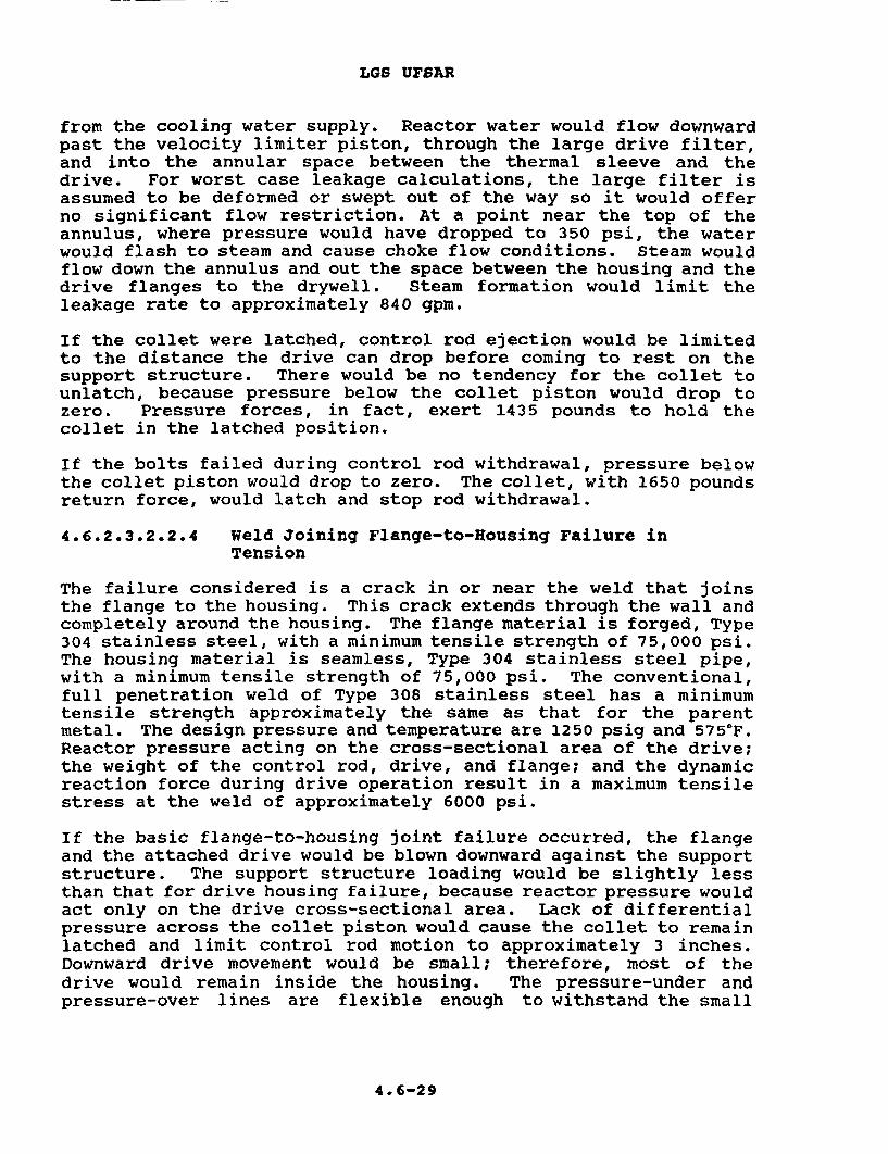
LGS UFSAR
from the cooling water supply. Reactor water would flow downwardpast the velocity limiter piston, through the large drive filter,and into the annular space between the thermal sleeve and thedrive. For worst case leakage calculations, the large filter isassumed to be deformed or swept out of the way so it would offerno significant flow restriction. At a point near the top of theannulus, where pressure would have dropped to 350 psi, the waterwould flash to steam and cause choke flow conditions. Steam wouldflow down the annulus and out the space between the housing and thedrive flanges to the drywell. Steam formation would limit theleakage rate to approximately 840 gpm.
If the collet were latched, control rod ejection would be limitedto the distance the drive can drop before coming to rest on thesupport structure. There would be no tendency for the collet tounlatch, because pressure below the collet piston would drop tozero. Pressure forces, in fact, exert 1435 pounds to hold thecollet in the latched position.
If the bolts failed during control rod withdrawal, pressure belowthe collet piston would drop to zero. The collet, with 1650 poundsreturn force, would latch and stop rod withdrawal.
4.6.2.3.2.2.4 Weld Joining Flange-to-Housing Failure inTension
The failure considered is a crack in or near the weld that joinsthe flange to the housing. This crack extends through the wall andcompletely around the housing. The flange material is forged, Type304 stainless steel, with a minimum tensile strength of 75,000 psi.The housing material is seamless, Type 304 stainless steel pipe,with a minimum tensile strength of 75,000 psi. The conventional,full penetration weld of Type 308 stainless steel has a minimumtensile strength approximately the same as that for the parentmetal. The design pressure and temperature are 1250 psig and 5757F.Reactor pressure acting on the cross-sectional area of the drive;the weight of the control rod, drive, and flange; and the dynamicreaction force during drive operation result in a maximum tensilestress at the weld of approximately 6000 psi.
If the basic flange-to-housing joint failure occurred, the flangeand the attached drive would be blown downward against the supportstructure. The support structure loading would be slightly lessthan that for drive housing failure, because reactor pressure wouldact only on the drive cross-sectional area. Lack of differentialpressure across the collet piston would cause the collet to remainlatched and limit control rod motion to approximately 3 inches.Downward drive movement would be small; therefore, most of thedrive would remain inside the housing. The pressure-under andpressure-over lines are flexible enough to withstand the small
4. 6-29

LGS UFSAR
displacement and remain attached to the flange. Reactor waterwould follow the same leakage path described above for the flangebolt failure, except that exit to the drywell would be through thegap between the lower end of the housing and the top of the flange.Water would flash to steam in the annulus surrounding the drive.The leakage rate would be approximately 840 gpm.
If the basic failure were to occur during control rod withdrawal(a small fraction of the total operating time) and if the colletwere held unlatched, the flange would separate from the housing.The drive and flange would be blown downward against the supportstructure. The calculated steady-state rod withdrawal velocitywould be 0.13 ft/sec. Because pressure-under and pressure-overlines remain intact, driving water pressure would continue to thedrive, and the normal exhaust line restriction would exist. Thepressure below the velocity limiter piston would drop below normalas a result of leakage from the gap between the housing and theflange. This differential pressure across the velocity limiterpiston would result in a net downward force of approximately 70pounds. Leakage out of the housing would greatly reduce thepressure in the annulus surrounding the drive. Thus, the netdownward force on the drive piston would be less than normal. Theoverall effect of these events would be to reduce rod withdrawalto approximately one-half of normal speed. With a 560-psidifferential across the collet piston, the collet would remainunlatched; however, it should relatch as soon as the drive signalis removed.
4.6.2.3.2.2.5 Housing Wall Ruptures
This failure is a vertical split in the drive housing wall justbelow the bottom head of the reactor vessel. The flow area of thehole is considered equivalent to the annular area between the driveand the thermal sleeve. Thus, flow through this annular area,rather than flow through the hole in the housing, would governleakage flow. The housing is made of Type 304 stainless steelseamless pipe, with a minimum tensile strength of 75,000 psi. Themaximum hoop stress of 11,900 psi results primarily from thereactor design pressure (1250 psig) acting on the inside of thehousing.
If such a rupture were to occur, reactor water would flash tosteam, and leak through the hole in the housing to the drywell atapproximately 1030 gpm. Choke flow conditions would exist, asdescribed previously for the flange bolt failure. However, leakageflow would be greater because flow resistance would be less, thatis, the leaking water and steam would not have to flow down thelength of the housing to reach the drywell. A critical pressureof 350 psi causes the water to flash to steam.
4.6-30
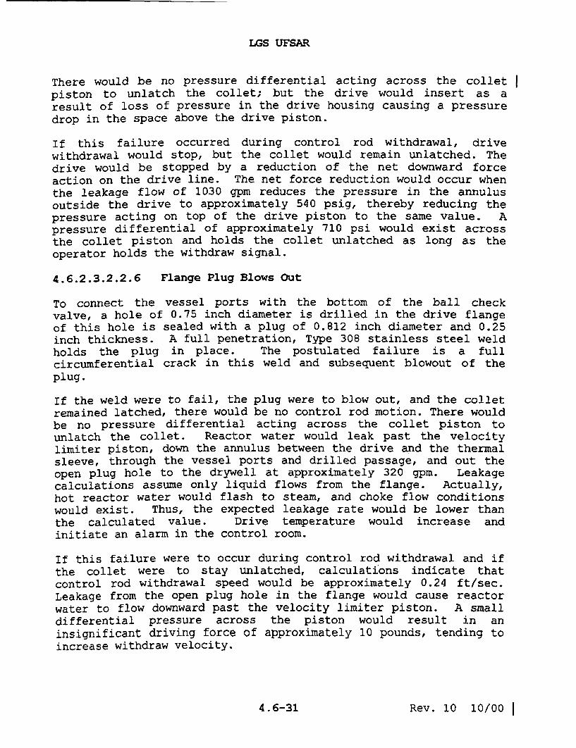
LGS UFSAR
There would be no pressure differential acting across the collet
piston to unlatch the collet; but the drive would insert as a
result of loss of pressure in the drive housing causing a pressure
drop in the space above the drive piston.
If this failure occurred during control rod withdrawal, drivewithdrawal would stop, but the collet would remain unlatched. The
drive would be stopped by a reduction of the net downward force
action on the drive line. The net force reduction would occur when
the leakage flow of 1030 gpm reduces the pressure in the annulus
outside the drive to approximately 540 psig, thereby reducing the
pressure acting on top of the drive piston to the same value. A
pressure differential of approximately 710 psi would exist acrossthe collet piston and holds the collet unlatched as long as theoperator holds the withdraw signal.
4.6.2.3.2.2.6 Flange Plug Blows Out
To connect the vessel ports with the bottom of the ball checkvalve, a hole of 0.75 inch diameter is drilled in the drive flangeof this hole is sealed with a plug of 0.812 inch diameter and 0.25inch thickness. A full penetration, Type 308 stainless steel weldholds the plug in place. The postulated failure is a full
circumferential crack in this weld and subsequent blowout of theplug.
If the weld were to fail, the plug were to blow out, and the colletremained latched, there would be no control rod motion. There wouldbe no pressure differential acting across the collet piston to
unlatch the collet. Reactor water would leak past the velocitylimiter piston, down the annulus between the drive and the thermalsleeve, through the vessel ports and drilled passage, and out theopen plug hole to the drywell at approximately 320 gpm. Leakage
calculations assume only liquid flows from the flange. Actually,hot reactor water would flash to steam, and choke flow conditionswould exist. Thus, the expected leakage rate would be lower than
the calculated value. Drive temperature would increase andinitiate an alarm in the control room.
If this failure were to occur during control rod withdrawal and if
the collet were to stay unlatched, calculations indicate thatcontrol rod withdrawal speed would be approximately 0.24 ft/sec.Leakage from the open plug hole in the flange would cause reactorwater to flow downward past the velocity limiter piston. A small
differential pressure across the piston would result in an
insignificant driving force of approximately 10 pounds, tending toincrease withdraw velocity.
4.6-31 Rev. 10 10/00

LGS UFSAR
A pressure differential of 295 psi across the collet piston wouldhold the collet unlatched as long as the driving signal wasmaintained.
Flow resistance of the exhaust path from the drive would be normalbecause the ball check valve would be seated at the lower end ofits travel by pressure under the drive piston.
4.6.2.3.2.2.7 Ball Check Valve Plug Blows Out
As a means of access for machining the ball check valve cavity, a1.25 inch diameter hole has been drilled in the flange forging.This hole is sealed with a plug with a 1.31 inch diameter and 0.38inch thickness. A full penetration weld, utilizing Type 308stainless steel filler, holds the plug in place. The failurepostulated is a circumferential crack in this weld leading to ablowout of the plug.
If the plug were to blow out while the drive was latched, therewould be no control rod motion. No pressure differential wouldexist across the collet piston to unlatch the collet. As in theprevious failure, reactor water would flow past the velocitylimiter, down the annulus between the drive and thermal sleeve,through the vessel ports and drilled passage, through the ballcheck valve cage and out the open plug hole to the drywell. Theleakage calculations indicate that the flow rate would be 350 gpm.This calculation assumes liquid flow, but flashing of the hotreactor water to steam would reduce this rate to a lower value.Drive temperature would rapidly increase and initiate an alarm inthe control room.
If the plug failure were to occur during control rod withdrawal,(it would not be possible to unlatch the drive after such afailure) the collet would relatch at the first locking groove. Ifthe collet were to stick, calculations indicate the control rodwithdrawal speed would be 11.8 ft/sec. There would be a largeretarding force exerted by the velocity limiter due to a 35 psipressure differential across the velocity limiter piston.
4.6.2.3.2.2.8 Drive/Cooling Water Pressure Control ValveClosure (Reactor Pressure, 0 psig)
The pressure to move a drive is generated by the pressure drop ofpractically the full system flow through the drive/cooling waterpressure control valve. This valve is either a MOV or a standbymanual valve; either one is adjusted to a fixed opening. Thenormal pressure drop across this valve develops a pressure 260 psiin excess of reactor pressure.
4.6-32

LGS UFSAR
If the flow through the drive/cooling water pressure control valvewere to be stopped, as by a valve closure or flow blockage, thedrive pressure would increase to the shutoff pressure of the supplypump. The occurrence of this condition during withdrawal of adrive at zero vessel pressure will result in a drive pressureincrease from 260 psig to no more than 1750 psig. Calculationsindicate that the drive accelerates from 3 in/sec to approximately6.5 in/sec. A pressure differential of 1670 psi across the colletpiston would hold the collet unlatched. Flow would be upward, pastthe velocity limiter piston, but retarding force would benegligible. Rod movement would stop as soon as the driving signalwas removed.
4.6.2.3.2.2.9 Ball Check Valve Fails to Close Passage toVessel Ports
Should the ball check valve sealing the passage to the vessel portsbe dislodged and prevented from reseating following the insertportion of a drive withdrawal sequence, water below the drivepiston would return to the reactor through the vessel ports and theannulus between the drive and the housing rather than through thespeed control valve. Because the flow resistance of this returnpath would be lower than normal, the calculated withdrawal speedwould be 2 ft/sec. During withdrawal, differential pressure acrossthe collet piston would be approximately 40 psi. Therefore, thecollet would tend to latch and would have to stick open beforecontinuous withdrawal at 2 ft/sec could occur. Water would flowupward past the velocity limiter piston, generating a smallretarding force of approximately 120 pounds.
4.6.2.3.2.2.10 Hydraulic Control Unit Valve Failures
Various failures of the valves in the HCU can be postulated, butnone could produce differential pressures approaching thosedescribed in the preceding paragraphs, and none alone could producea high velocity withdrawal. Leakage through either one or both ofthe scram valves produces a pressure that tends to insert thecontrol rod rather than to withdraw it. If the pressure in theSDV should exceed reactor pressure following a scram, a check valvein the line to the scram discharge header prevents this pressurefrom operating the drive mechanisms.
4. 6-33

LGS UFSAR
4.6.2.3.2.2.11 Collet Fingers Pail to Latch
The failure is presumed to occur when the drive withdraw signal isremoved. If the collet fails to latch, the drive continues towithdraw at a fraction of the normal speed. This assumption ismade because there is no known means for the collet fingers tobecome unlocked without some initiating signal. Because the colletfingers will not cam open under a load, accidental application ofa down signal does not unlock them. (The drive must be given ashort insert signal to unload the fingers and cam them open beforethe collet can be driven to the unlock position.) If the drivewithdrawal valve fails to close following a rod withdrawal, thecollet would remain open and the drive would continue to move ata reduced speed.
4.6.2.3.2.2.12 Withdrawal Speed Control Valve Failure
Normal withdrawal speed is determined by differential pressures inthe drive and is set for a nominal value of 3 in/sec. Withdrawalspeed is maintained by the pressure regulating system and isindependent of reactor vessel pressure. Tests show that accidentalopening of the speed control valve to the fully open positionproduces a velocity of approximately 6 in/sec.
The CRD system prevents unplanned rod withdrawal, and it has beenshown above that only multiple failures in a drive unit and in itscontrol unit could cause an unplanned rod withdrawal.
4.6.2.3.2.3 Scram Reliability
High scram reliability is the result of a number of features of theCRD system. For example:
a. Two reliable sources of scram energy are used to inserteach control rod: individual accumulators at low reactorpressure, and the reactor vessel pressure itself atpower.
b. Each drive mechanism has its own scram valves and twoscram pilot valves, so only one drive can be affected ifa scram valve fails to open. Both pilot valves must bede-energized to initiate a scram.
c. The RPS and the HCUs are designed so that the scramsignal and mode of operation override all others.
4 .6-34

LGS UFSAR
d. The collet assembly and index tube are designed so theydo not restrain or prevent control rod insertion duringscram.
e. The SDV is monitored for accumulated water and thereactor scrams before the volume is reduced to a pointthat could interfere with a scram.
4.6.2.3.2.4 Control Rod Support and Operation
As described above, each control rod is independently supported andcontrolled as required by safety design bases.
4.6.2.3.3 Control Rod Drive Housing Supports
Downward travel of the CRD housing and its control rod followingthe postulated housing failure equals the sum of these distances:the compression of the disc springs under dynamic loading, and theinitial gap between the grid and the bottom contact surface of theCRD flange. If the reactor were cold and pressurized, the downwardmotion of the control rod would be limited to the springcompression (approximately 2 inches) plus a gap of approximately3/4" + 1/4". If the reactor were hot and pressurized, the gapwould be approximately 1/2" i 1/4" and the spring compression wouldbe slightly less than in the cold condition. In either case, thecontrol rod movement following a housing failure is substantiallylimited below one drive "notch" movement (6 inches). Suddenwithdrawal of any control rod, through a distance of one drivenotch at any position in the core, does not produce a transientsufficient to damage any radioactive material barrier.
The CRD housing supports are in place during power operation andwhen the nuclear system is pressurized. If a control rod isejected during shutdown, the reactor remains subcritical because itis designed to remain subcritical with any one control rod fullywithdrawn at any time.
At plant operating temperature, a gap of approximately 1/2" ± 1/4"exists between the CRD housing and the supports. At lowertemperatures the gap is greater. Because the supports do notcontact any of the CRD housing, except during the postulatedaccident condition, vertical contact stresses are prevented.Inspection and testing are discussed in Section 4.6.3.2.
4.6-35 Rev. 3 Nov./93
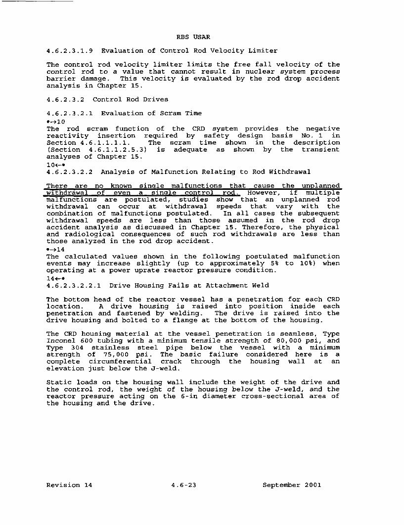
RBS USAR
4.6.2.3.1.9 Evaluation of Control Rod Velocity Limiter
The control rod velocity limiter limits the free fall velocity of thecontrol rod to a value that cannot result in nuclear system processbarrier damage. This velocity is evaluated by the rod drop accidentanalysis in Chapter 15.
4.6.2.3.2 Control Rod Drives
4.6.2.3.2.1 Evaluation of Scram Time
*-1 0The rod scram function of the CRD system provides the negativereactivity insertion required by safety design basis No. 1 inSection 4.6.1.1.1.1. The scram time shown in the description(Section 4.6.1.1.2.5.3) is adequate as shown by the transientanalyses of Chapter 15.10F*4.6.2.3.2.2 Analysis of Malfunction Relating to Rod Withdrawal
There are no known single malfunctions that cause the unplannedwithdrawal of even a sinale control rod. However, if multiplemalfunctions are postulated, studies show that an unplanned rodwithdrawal can occur at withdrawal speeds that vary with thecombination of malfunctions postulated. In all cases the subsequentwithdrawal speeds are less than those assumed in the rod dropaccident analysis as discussed in Chapter 15. Therefore, the physicaland radiological consequences of such rod withdrawals are less thanthose analyzed in the rod drop accident.*->14The calculated values shown in the following postulated malfunctionevents may increase slightly (up to approximately 5% to 10%) whenoperating at a power uprate reactor pressure condition.14+-.4.6.2.3.2.2.1 Drive Housing Fails at Attachment Weld
The bottom head of the reactor vessel has a penetration for each CRDlocation. A drive housing is raised into position inside eachpenetration and fastened by welding. The drive is raised into thedrive housing and bolted to a flange at the bottom of the housing.
The CRD housing material at the vessel penetration is seamless, TypeInconel 600 tubing with a minimum tensile strength of 80,000 psi, andType 304 stainless steel pipe below the vessel with a minimumstrength of 75,000 psi. The basic failure considered here is acomplete circumferential crack through the housing wall at anelevation just below the J-weld.
Static loads on the housing wall include the weight of the drive andthe control rod, the weight of the housing below the J-weld, and thereactor pressure acting on the 6-in diameter cross-sectional area ofthe housing and the drive.
Revision 14 4.6-23 September 2001

RBS USAR
Dynamic loading results from the reaction force during driveoperation.
If the housing were to fail as described, the following sequenceof events is foreseen. The housing would separate from thevessel. The CRD and housing would be blown downward against thesupport structure by reactor pressure acting on thecross-sectional area of the housing and the drive. The downwardmotion of the drive and associated parts would be determined bythe gap between the bottom of the drive and the support structureand by the deflection of the support structure under load. Inthe current design, maximum deflection is approximately 3 in. Ifthe collet were to remain latched, no further control rodejection would occur"'t , the housing would not drop far enough toclear the vessel penetration, and reactor water would leak at arate of approximately 180 gpm through the 0.03-in diametralclearance between the housing and the vessel penetration.
If the basic housing failure were to occur while the control rodis being withdrawn (this is a small fraction of the total driveoperating time) and if the collet were to stay unlatched, thefollowing sequence of events is foreseen. The housing wouldseparate from the vessel and the drive and housing would be blowndownward against the CRD housing support. Calculations indicatethat the steady-state rod withdrawal velocity would be 0.3ft/sec. During withdrawal, pressure under the collet piston wouldbe approximately 250 psi greater than the pressure over it.Therefore, the collet would be held in the unlatched positionuntil driving pressure was removed from the pressure-over port.
4.6.2.3.2.2.2 Rupture of Hydraulic Line(s) to Drive HousingFlange
There are three types of possible rupture of hydraulic lines tothe drive housing flange: 1) pressure-under (insert) line break,2) pressure-over (withdrawn) line break, and 3) coincidentbreakage of both these lines.
4.6.2.3.2.2.2.1 Pressure-Under (Insert) Line Break
For the case of a pressure-under (insert) line break, a partialor complete circumferential opening is postulated at or near thepoint where the line enters the housing flange. Failure is morelikely to occur after another basic failure wherein the drivehousing or housing flange separates from the reactor vessel.Failure of the housing, however, does not necessarily leaddirectly to failure of the hydraulic lines.
4. 6-24 August 1987

RBS USAR
If the pressure-under (insert) line were to fail and if the
collet were latched, no control rod withdrawal would occur. There
would be no pressure differential across the collet piston and,
therefore, no tendency to unlatch the collet. Consequently, the
associated control rod could not be withdrawn, but if reactor
pressure is greater than 600 psig, it will insert on a scram
signal.
The ball check valve is designed to seal off a broken
pressure-under line by using reactor pressure to shift the check
ball to its upper seat. If the ball check valve were preventedfrom seating, reactor water would leak to the containment.Because of the broken line, cooling water could not be supplied
to the drive involved. Loss of cooling water would cause no
immediate damage to the drive. However, prolonged exposure of the
drive to temperatures at or near reactor temperature could lead
to deterioration of material in the seals. High temperaturewould be indicated to the operator by the thermocouple in the
position indicator probe. A second indication would be high
cooling water flow.
If the basic line failure were to occur while the control rod is
being withdrawn the hydraulic force would not be sufficient to
hold the collet open, and spring force normally would cause the
collet to latch and stop rod withdrawal. However, if the collet
were to remain open, calculations indicate that the steady-statecontrol rod withdrawal velocity would be 2 ft/sec.
4.6.2.3.2.2.2.2 Pressure-Over (Withdrawn) Line Break
The case of the pressure-over (withdrawn) line breakage considers
the complete breakage of the line at or near the point where it
enters the housing flange. If the line were to break, pressure
over the drive piston would drop from reactor pressure to
atmospheric pressure. Any significant reactor pressure
(approximately 600 psig or greater) would act on the bottom of
the drive piston and fully insert the drive. Insertion would
occur regardless of the operational mode at the time of the
failure. After full insertion, reactor water would leak past thestop piston seals. This leakage would exhaust to the containmentthrough the broken pressure-over line. The leakage rate at 1,000
psi reactor pressure is estimated to be 1 to 3 gpm, however with
the graphitar seals of the stop piston removed, the leakage rate
could be as high as 10 gpm, based on experimental measurements.If the reactor were hot, drive temperature would increase. This
situation would be indicated to the reactor operator by the drift
alarm, by the fully inserted drive, by a high drive temperatureannunciated in the main
4. 6-25 August 1987

RBS USAR
control room, by sump water level change detected by thehigh-sensitivity drywell-sump leak detection system, and byoperation of the drywell sump pump.
4.6.2.3.2.2.2.3 Simultaneous Breakage of the Pressure-Over(Withdrawn) and Pressure-Under (Insert) Lines
For the simultaneous breakage of the pressure-over (withdrawn)and pressure-under (insert) lines, pressures above and below thedrive piston would drop to zero, and the ball check valve wouldclose the broken pressure-under line. Reactor water would flowfrom the annulus outside the drive, through the vessel ports, andto the space below the drive piston. As in the case ofpressure-over line breakage, the drive would then insert (atreactor pressure approximately 600 psig or greater) at a speeddependent on reactor pressure. Full insertion would occurregardless of the operational mode at the time of failure.Reactor water would leak past the drive seals and out the brokenpressure-over line to the containment, as described above. Drivetemperature would increase. Indication in the main control roomwould include the drift alarm, the fully inserted drive, the highdrive temperature annunciated in the main control room, andoperation of the drywell sump pump.
4.6.2.3.2.2.3 All Drive Flange Bolts Fail in Tension
Each CRD is bolted to a flange at the bottom of a drive housing.The flange is welded to the drive housing. Bolts are made ofAISI-4140 steel with a minimum tensile strength of 125,000 psi.Each bolt has an allowable load capacity of 15,200 lb. Capacityof the eight bolts is 121,600 lb. As a result of the reactordesign pressure of 1,250 psig, the major load on all eight boltsis 30,400 lb.
If a progressive or simultaneous failure of all bolts were tooccur, the drive would separate from the housing. The controlrod and the drive would be blown downward against the supportstructure. Impact velocity and support structure loading wouldbe slightly less than that for drive housing failure, becausereactor pressure would act on the drive cross-sectional area onlyand the housing would remain attached to the reactor vessel. Thedrive would be isolated from the cooling water supply. Reactorwater would flow downward past the velocity limiter piston,through the large drive filter, and into the annular spacebetween the thermal sleeve and the drive. For worst-case leakagecalculations, the large filter is assumed to be deformed or sweptout of the way so it would offer no significant flow restriction.At a point near the top of the annulus, where pressure would
4. 6-26 August 1987

RBS USAR
have dropped to 350 psi, the water would flash to steam and causechoke-flow conditions. Steam would flow down the annulus and outthe space between the housing and the drive flanges to thedrywell. Steam formation would limit the leakage rate toapproximately 840 gpm.
If the collet were latched, control rod ejection would be limitedto the distance the drive can drop before coming to rest on thesupport structure. There would be no tendency for the collet tounlatch, because pressure below the collet piston would drop tozero. Pressure forces, in fact, exert 1,435 lb to hold thecollet in the latched position.
If the bolts failed during control rod withdrawal, pressure belowthe collet piston would drop to zero. The collet, with 1,650 lbreturn force, would latch and stop rod withdrawal.
4.6.2.3.2.2.4 Weld Joining Flange to Housing Fails in Tension
The failure considered is a crack in or near the weld that joinsthe flange to the housing. This crack extends through the walland completely around the housing. The flange material isforged, Type 304 stainless steel, with a minimum tensile strengthof 75,000 psi. The housing material is seamless, Type 304stainless steel pipe, with a minimum tensile strength of 75,000psi. The conventional, full penetration weld of Type 308stainless steel has a minimum tensile strength approximately thesame as that for the parent metal. The design pressure andtemperature are 1,250 psig and 5750F. Reactor pressure acting onthe cross-sectional area of the drive; the weight of the controlrod, drive, and flange; and the dynamic reaction force duringdrive operation result in a maximum tensile stress at the weld ofapproximately 5,100 psi.
If the basic flange-to-housing joint failure occurred, the flangeand the attached drive would be blown downward against thesupport structure. The support structure loading would beslightly less than that for drive housing failure, becausereactor pressure would act only on the drive cross-sectionalarea. Lack of differential pressure across the collet pistonwould cause the collet to remain latched and limit control rodmotion to approximately 3 in. Downward drive movement would besmall; therefore, most of the drive would remain inside thehousing. The pressure-under and pressure-over lines are flexibleenough to with- stand the small displacement and remain attachedto the flange. Reactor water would follow the same leakage pathdescribed above for the flange-bolt failure, except that
4. 6-27 August 1987

RBS USAR
exit to the drywell would be through the gap between the lowerend of the housing and the top of the flange. Water would flashto steam in the annulus surrounding the drive. The leakage ratewould be approximately 840 gpm.
If the basic failure were to occur during control rod withdrawal(a small fraction of the total operating time) and if the colletwere held unlatched, the flange would separate from the housing.The drive and flange would be blown downward against the supportstructure. The calculated steady-state rod withdrawal velocitywould be 0.13 ft/sec. Because pressure-under and pressure-overlines remain intact, driving water pressure would continue to thedrive, and the normal exhaust line restriction would exist. Thepressure below the velocity limiter piston would drop belownormal as a result of leakage from the gap between the housingand the flange. This differential pressure across the velocitylimiter piston would result in a net downward force ofapproximately 70 lb. Leakage out of the housing would greatlyreduce the pressure in the annulus surrounding the drive. Thus,the net downward force on the drive piston would be less thannormal. The overall effect of these events would be to reducerod withdrawal to approximately one-half of normal speed. With a560-psi differential across the collet piston, the collet wouldremain unlatched; however, it should relatch as soon as the drivesignal is removed.
4.6.2.3.2.2.5 Housing Wall Ruptures
This failure is a vertical split in the drive housing wall justbelow the bottom head of the reactor vessel. The flow area ofthe hole is considered equivalent to the annular area between thedrive and the thermal sleeve. Thus, flow through this annulararea, rather than flow through the hole in the housing, wouldgovern leakage flow. The CRD housing is made of Inconel 600seamless tubing (at the penetration to the vessel), with aminimum tensile strength of 80,000 psi, and of Type 304 stainlesssteel seamless pipe below the vessel with a minimum tensilestrength of 75,000 psi. The maximum hoop stress of 9,000 psiresults primarily from the reactor design pressure (1,250 psig)acting on the inside of the housing.
If such a rupture were to occur, reactor water would flash tosteam and leak through the hole in the housing to the drywell atapproximately 1,030 gpm. Choke-flow conditions would exist, asdescribed previously for the flange-bolt failure. However,leakage flow would be greater because flow resistance would beless, that is, the leaking water and steam would not have to flowdown the length of the
4.6-28 August 1987

RBS USAR
housing to reach the drywell. A critical pressure of 350 psicauses the water to flash to steam.
There would be no pressure differential acting across the colletpiston to unlatch the collet; but the drive would insert as aresult of loss of pressure in the drive housing causing apressure drop in the space above the drive piston.
If this failure occurred during control rod withdrawal, drivewithdrawal would stop, but the collet would remain unlatched.The drive would be stopped by a reduction of the net downwardforce action on the drive line. The net force reduction wouldoccur when the leakage flow of 1,030 gpm reduces the pressure inthe annulus outside the drive to approximately 540 psig, therebyreducing the pressure acting on top of the drive piston to thesame value. A pressure differential of approximately 710 psiwould exist across the collet piston and hold the colletunlatched as long as the operator held the withdraw signal.
4.6.2.3.2.2.6 Flange Plug Blows Out
To connect the vessel ports with the bottom of the ball checkvalve, a hole of 3/4-in diameter is drilled in the drive flange.The outer end of this hole is sealed with a plug of 0.812-indiameter and 0.25-in thickness. A full-penetration, Type 308stainless steel weld holds the plug in place. The postulatedfailure is a full circumferential crack in this weld andsubsequent blowout of the plug.
If the weld were to fail, the plug were to blow out, and thecollet remained latched, there would be no control rod motion.There would be no pressure differential acting across the colletpiston to unlatch the collet. Reactor water would leak past thevelocity limiter piston, down the annulus between the drive andthe thermal sleeve, through the vessel ports and drilled passage,and out the open plug hole to the drywell at approximately320 gpm. Leakage calculations assume only liquid flows from theflange. Actually, hot reactor water would flash to steam, andchoke-flow conditions would exist. Thus, the expected leakagerate would be lower than the calculated value. Drive temperaturewould increase and initiate an alarm in the main control room.
If this failure were to occur during control rod withdrawal andif the collet were to stay unlatched, calculations indicate thatcontrol rod withdrawal speed would be approximately 0.24 ft/sec.Leakage from the open plug hole in the flange would cause reactorwater to flow downward past the velocity limiter piston. A smalldifferential
4. 6-29 August 1987
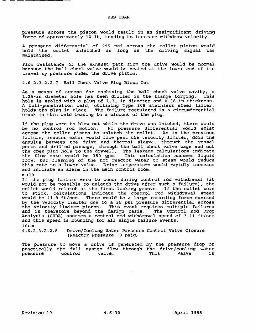
RBS USAR
pressure across the piston would result in an insignificant drivingforce of approximately 10 lb, tending to increase withdraw velocity.
A pressure differential of 295 psi across the collet piston wouldhold the collet unlatched as long as the driving signal wasmaintained.
Flow resistance of the exhaust path from the drive would be normalbecause the ball check valve would be seated at the lower end of itstravel by pressure under the drive piston.
4.6.2.3.2.2.7 Ball Check Valve Plug Blows Out
As a means of access for machining the ball check valve cavity, a1.25-in diameter hole has been drilled in the flange forging. Thishole is sealed with a plug of 1.31-in diameter and 0.38-in thickness.A full-penetration weld, utilizing Type 308 stainless steel filler,holds the plug in place. The failure postulated is a circumferentialcrack in this weld leading to a blowout of the plug.
If the plug were to blow out while the drive was latched, there wouldbe no control rod motion. No pressure differential would existacross the collet piston to unlatch the collet. As in the previousfailure, reactor water would flow past the velocity limiter, down theannulus between the drive and thermal sleeve, through the vesselports and drilled passage, through the ball check valve cage and outthe open plug hole to the drywell. The leakage calculations indicatethe flow rate would be 350 gpm. This calculation assumes liquidflow, but flashing of the hot reactor water to steam would reducethis rate to a lower value. Drive temperature would rapidly increaseand initiate an alarm in the main control room.*-+10If the plug failure were to occur during control rod withdrawal (itwould not be possible to unlatch the drive after such a failure), thecollet would relatch at the first locking groove. If the collet wereto stick, calculations indicate the control rod withdrawal speedwould be 11.8 ft/sec. There would be a large retarding force exertedby the velocity limiter due to a 35 psi pressure differential acrossthe velocity limiter piston. This event requires multiple failuresand is therefore beyond the design basis. The Control Rod DropAnalysis (CRDA) assumes a control rod withdrawal speed of 3.11 ft/secand this speed is bounding for all single failure events.104-04.6.2.3.2.2.8 Drive/Cooling Water Pressure Control Valve Closure
(Reactor Pressure, 0 psig)
The pressure to move a drive is generated by the pressure drop ofpractically the full system flow through the drive/cooling waterpressure control valve. This valve is
Revision 10 4.6-30 April 1998
RBS USAR
either a motor-operated valve or a standby manual valve; eitherone is adjusted to a fixed opening. The normal pressure dropacross this valve develops a pressure 260 psi in excess ofreactor pressure.
If the flow through the drive/cooling water pressure controlvalve were to be stopped, as by a valve closure or flow blockage,the drive pressure would increase to the shutoff pressure of thesupply pump. The occurrence of this condition during withdrawalof a drive at zero vessel pressure will result in a drivepressure increase from 260 psig to no more than 2,000 psig.Calculations indicate that the drive would accelerate from 3in/sec to approximately 7 in/sec. A pressure differential of1,970 psi across the collet piston would hold the colletunlatched. Flow would be upward, past the velocity limiterpiston, but retarding force would be negligible. Rod movementwould stop as soon as the driving signal was removed.
4.6.2.3.2.2.9 Ball Check Valve Fails to Close Passage to VesselPorts
Should the ball check valve sealing the passage to the vesselports be dislodged and prevented from reseating following theinsert portion of a drive withdrawal sequence, water below thedrive piston would return to the reactor through the vessel portsand the annulus between the drive and the housing rather thanthrough the speed control valve. Because the flow resistance ofthis return path would be lower than normal, the calculatedwithdrawal speed would be 2 ft/sec. During withdrawal,differential pressure across the collet piston would beapproximately 40 psi. Therefore, the collet would tend to latchand would have to stick open before continuous withdrawal at 2ft/sec could occur. Water would flow upward past the velocitylimiter piston, generating a small retarding force ofapproximately 120 lb.
4.6.2.3.2.2.10 Hydraulic Control Unit Valve Failures
Various failures of the valves in the HCU can be postulated, butnone could produce differential pressures approaching thosedescribed in the preceding sections and none alone could producea high velocity withdrawal. Leakage through either one or bothof the scram valves produces a pressure that tends to insert thecontrol rod rather than to withdraw it. If the pressure in thescram discharge volume should exceed reactor pressure following ascram, a check valve in the line to the scram discharge headerprevents this pressure from operating the drive mechanisms.
4.6-31 August 1987
RBS USAR
4.6.2.3.2.2.11 Collet Fingers Fail to Latch
The failure is presumed to occur when the drive withdraw signalis removed. If the collet fails to latch, the drive continues towith- draw at a fraction of the normal speed. This assumption ismade because there is no known means for the collet fingers tobecome unlocked without some initiating signal. Because thecollet fingers will not cam open under a load, accidentalapplication of a down signal does not unlock them. (The drivemust be given a short insert signal to unload the fingers and camthem open before the collet can be driven to the unlockposition.) If the drive withdrawal valve fails to close followinga rod withdrawal, the collet would remain open and the drivecontinue to move at a reduced speed.
4.6.2.3.2.2.12 Withdrawal Speed Control Valve Failure
Normal withdrawal speed is determined by differential pressuresin the drive and is set for a nominal value of 3 in/sec.Withdrawal speed is maintained by the pressure regulating systemand is independent of reactor vessel pressure. Tests have shownthat accidental opening of the speed control valve to thefull-open position produces a velocity of approximately 5 in/sec.
The CRD system prevents unplanned rod withdrawal and it has beenshown above that only multiple failures in a drive unit and inits control unit could cause an unplanned rod withdrawal.
4.6.2.3.2.3 Scram Reliability
High scram reliability is the result of a number of features ofthe CRD system. For example:
1. An individual accumulator is provided for each CRD withsufficient stored energy to scram at any reactorpressure. The reactor vessel itself, at pressuresabove 600 psi, will supply the necessary force toinsert a drive if its accumulator is unavailable.
2. Each drive mechanism has its own scram valves and adual solenoid scram pilot valve; therefore, only onedrive can be affected if a scram valve fails to open.Both pilot valve solenoids must be deenergized toinitiate a scram.
3. The RPS and the HCUs are designed so that the scramsignal and mode of operation override all others.
4 .6-32 August 1987

RBS USAR
4. The collet assembly and index tube are designed so theywill not restrain or prevent control rod insertion duringscram.
5. The scram discharge volume is monitored for accumulatedwater and the reactor will scram before the volume isreduced to a point that could interfere with a scram.
6. The Alternate Rod Insertion (ARI) system is designed suchthat in the event an RPS scram signal is not received, anindependate means is available to automatically vent thescram air header.
1*-4.6.2.3.2.4 Control Rod Support and Operation
As described in the preceding sections, each control rod isindependently supported and controlled as required by safety designbases.
4.6.2.3.3 Control Rod Drive Housing Supports
Downward travel of the CRD housing and its control rod following thepostulated housing failure equals the sum of these distances: 1)the compression of the disc springs under dynamic loading, and 2)the initial gap between the grid and the bottom contact surface ofthe CRD flange. If the reactor were cold and pressurized, thedownward motion of the control rod would be limited to the springcompression (approximately 2 in) plus a gap of approximately 1 in.If the reactor were hot and pressurized, the gap would beapproximately 3/4 in and the spring compression would be slightlyless than in the cold condition. In either case, the control rodmovement following a housing failure is substantially limited belowone drive "notch" movement (6 in). Sudden withdrawal of any controlrod through a distance of one drive notch at any position in thecore does not produce a transient sufficient to damage anyradioactive material barrier.
The CRD housing supports are in place during power operation andwhen the nuclear system is pressurized. If a control rod is ejectedduring shutdown, the reactor remains subcritical because it isdesigned to remain subcritical with any one control rod fullywithdrawn at any time.0-410At plant operating temperature, a gap of approximately 3/4 in existsbetween the CRD housing and the supports. At lower temperatures thegap is greater. Because the supports do not contact any of the CRDhousing except during the postulated accident condition, verticalcontact stresses are prevented. Inspection and testing of CRDhousing supports is discussed in Section 4.6.3.2.10<-*
Revision 10 4. 6-33 April 1998
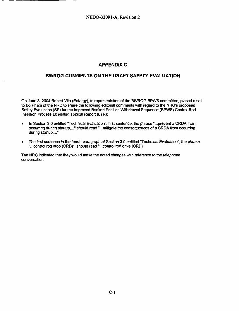
NEDO-33091-A, Revision 2
APPENDIX C
BWROG COMMENTS ON THE DRAFT SAFETY EVALUATION
On June 3, 2004 Robert Vita (Entergy), in representation of the BWROG BPWS committee, placed a callto Bo Pham of the NRC to share the following editorial comments with regard to the NRC's proposedSafety Evaluation (SE) for the Improved Banked Position Withdrawal Sequence (BPWS) Control RodInsertion Process Licensing Topical Report (LTR):
* In Section 3.0 entitled "Technical Evaluation", first sentence, the phrase "...prevent a CRDA fromoccurring during startup,..." should read "...mitigate the consequences of a CRDA from occurringduring startup,..."
* The first sentence in the fourth paragraph of Section 3.0 entitled 'Technical Evaluation", the phrase"...control rod drop (CRD)" should read "...control rod drive (CRD)"
The NRC indicated that they would make the noted changes with reference to the telephoneconversation.
C-I