b series controller communications vi library - …integratedpro.com/content/downloads/b series...
TRANSCRIPT

B series Controller Communications VI Library
User Manual: Version 1.0
Copyright © 2009 Integrated Pro http://www.integratedpro.com

Copyright © 2009 Integrated Pro. ALL RIGHTS RESERVED. http://www.integratedpro.com
‐ 2 ‐
Table of Contents
1. Introduction 2. Installation 3. Communications Setup 4. Using Example VIs 5. Creating Custom VIs 6. Library Reference 7. Optional Parameters
1. Introduction This VI library contains VIs and example code for implementing communication between LabVIEWTM from National Instruments and a Love Controls* B Series Controller via RS‐485 serial bus. Communication between LabVIEW and Single Loop Controllers (SLCs), such as a B series Controller, allows expanded capabilities such as the ability to log and trend the process value (PV) and setpoint value (SV) or to remotely change the SV or configuration values such as alarm limits. A single instance of LabVIEW running on a PC can access multiple SLCs throughout an installation via the RS‐485 bus to provide a central view or coordinated control and data acquisition capability at very low cost. It is assumed in this document that the reader is familiar with how to program and use LabVIEW. Hardware and wiring are beyond the scope of this document. If you need help setting up the RS‐485 serial bus, please consult the user manual for the Controller, your RS‐485 serial interface documentation or one of the numerous references on the internet. If you want to hire a consulting engineer, visit our www site: http://www.integratedpro.com CAUTION!!!! The VI library can change the configuration, setpoint or other operating parameters of your Controller(s) and/or other devices connected to the RS‐485 bus, resulting in changes to Controller behavior and especially if the Controller is connected to a physical process (i.e. operational and controlling something!) Never experiment with an operational controller – for development it is recommended to only use an offline controller, on an isolated RS‐485 serial bus. *Integrated Pro is not affiliated with Love Controls, a Division of Dwyer Instruments, Inc.

Copyright © 2009 Integrated Pro. ALL RIGHTS RESERVED. http://www.integratedpro.com
‐ 3 ‐
2. Installation Install the VI library by running the installation program, setup.exe. Choose the installation directory, and review the Software License Agreement. If you have multiple versions of LabVIEW, the VI library installs under the most current version of LabVIEW. Be sure to review the Readme.txt file information at the end of the installation. Restart LabVIEW after installing so that the library VIs will show up on the Tools palette (right click the block diagram). You can find them on the B Series palette under User Libraries. You can access help and example VIs under the LabVIEW Help menu.
3. Communications Setup Before using the VI library, you need to know three things:
1. Which communications port your RS‐485 serial interface is using to communicate with the Controller. You can then use this information to set the VISA Resource which LabVIEW will use to communicate with the controller.
2. The address of the Controller on the RS‐485 serial bus. This will be a number between 1 and 255.
3. The serial baud rate. By default, this is set to 9600 baud. Other serial settings should be set to 8 bit data, No parity, and 1 Stop bit.
Finding the Communications Port To find out this information, consult the documentation for your RS‐485 serial interface. Most RS‐485 serial interfaces install under Windows as a standard serial port, such as COM5, COM6, etc. In Windows, you can view the installed serial ports under the device manager. MAC OS and Linux have similar utilities. Finding the Controller Address and Serial Baud Rate On the B Series Controllers, the Controller address and serial settings are found using the Initial Setting Menu (press and hold the ENTER key for at least 3 seconds while at the Home Display). Consult the User Manual for further details. RS‐485 Serial Bus All devices on the RS‐485 serial bus must use the same serial baud rate, but have different addresses. LabVIEW acts as a serial Master device and the Controller acts as a Slave device. The VI library only supports RTU mode, not ASCII, communications. (note that some versions of the B series User Manual state that ASCII mode is used ‐ this is incorrect)

Copyright © 2009 Integrated Pro. ALL RIGHTS RESERVED. http://www.integratedpro.com
‐ 4 ‐
4. Using Example VIs Two VI examples are included with the VI library: B series Example Query Settings.vi and B series Example PV and SV panel and log.vi contained in the folder: [LabVIEW]\examples\B series Controller, where [LabVIEW] represents the path to your LabVIEW installation. Both of these VIs demonstrate how to use the subVIs contained in the VI library to communicate with the Controller and are meant to be starting points for verifying communication and for use in creating your own custom VIs. Example VIs can be accessed either under B series Controller Library on the LabVIEW Help menu or from the Tools Palette (right‐click on the block diagram). On the Tools Palette, choose the B series Controller palette under User Libraries as shown in Figure 1. When you drop on of the example VIs on a block diagram, it will automatically open to show the front panel.
Figure 1 ‐ B series Controller VIs under User Libraries on the Tools Palette
Copyright © 2009 Integrated Pro. ALL RIGHTS RESERVED. http://www.integratedpro.com
‐ 5 ‐
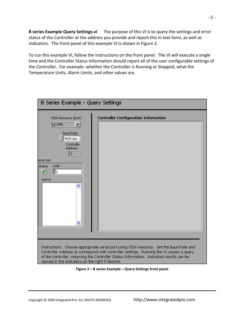
B series Example Query Settings.vi The purpose of this VI is to query the settings and error status of the Controller at the address you provide and report this in text form, as well as indicators. The front panel of this example VI is shown in Figure 2. To run this example VI, follow the instructions on the front panel. The VI will execute a single time and the Controller Status Information should report all of the user configurable settings of the Controller. For example: whether the Controller is Running or Stopped, what the Temperature Units, Alarm Limits, and other values are.
Figure 2 – B series Example – Query Settings front panel

Copyright © 2009 Integrated Pro. ALL RIGHTS RESERVED. http://www.integratedpro.com
‐ 6 ‐
B series Example PV and SV Panel and Log.vi The purpose of this VI is to simulate the front panel of the Controller, showing the PV and SV values, temperature units, alarm LEDs, output LEDs and autotune status LED. The trend values of PV and SV are also logged to a chart on the front panel at an update rate of approximately 1 second. The front panel of this example VI is shown in Figure 3. To run this example VI, follow the instructions on the front panel. The VI will execute in a loop, with an event structure controlling the update rate and responding to user input from the front panel controls. By default, the VI will only retrieve the values of PV, SV and the LEDs. By turning the Write Enable switch ON, the VI can be used to set the value of SV either by clicking on the UP or DOWN arrow buttons on the simulated Controller panel, or by entering a new value for the Update SV numeric control. The Up/Down increment controls how much the SV changes when clicking on the UP or DOWN arrow buttons.
Figure 3 ‐ B series Example ‐ PV and SV Panel and Log.vi front panel

Copyright © 2009 Integrated Pro. ALL RIGHTS RESERVED. http://www.integratedpro.com
‐ 7 ‐
5. Creating Custom VIs After using the example VIs to verify communications between LabVIEW and the Controller, you can use the VI library to create your own custom VIs or modify the examples. Here is a simple example showing how to use a few of the library VIs to develop a custom VI. CAUTION!!!! The VI library can change the configuration, setpoint or other operating parameters of your Controller(s) or other devices connected to the RS‐485 bus, resulting in changes to Controller behavior and especially if the Controller is connected to a physical process (i.e. operational and controlling something!) Never experiment with an operational controller – for development it is recommended to only use an offline controller, on an isolated RS‐485 serial bus. A Basic VI Application Start with a blank VI and access the VI library by right‐clicking on the block diagram of a new VI, choosing User Libraries from the Tools Palette and opening the B series Controller palette as shown in Figure 1. Make it stay open “Pinning” the palette (click the push‐pin icon in the upper left hand corner) of the B series Controller palette. Drag the following subVIs onto the block diagram and arrange them as shown in Figure 5: Initialize B series.vi, Close B series.vi, and Read Alarm LEDs B series.vi (from the Data subpalette). You can view the connector pane for each of the subVIs by turning on the LabVIEW context help (the ? button in the upper right of the block diagram window) and hovering with the mouse over each of the icons. Notice that there are required inputs on some of the subVIs, so connect these up to a control or a constant. When correctly wired, the front panel and block diagram should look similar to Figure 4 and Figure 5. Set the VISA resource name and baud rate, save the VI and run it. The state of the Alarm LEDs should now correspond to those on the Controller. Adding More Functionality The basic pattern for the subVIs on the block diagram is always similar to that shown in the simple example, except that the Initialize B series.vi and Close B series.vi subVIs are only called at the beginning and end of the application and only once for any particular RS‐485 serial bus, even if there are multiple Controllers. To further illustrate things, let’s add a timed loop to read the values of PV.

Copyright © 2009 Integrated Pro. ALL RIGHTS RESERVED. http://www.integratedpro.com
‐ 8 ‐
Figure 4 – Basic Application VI front panel
Figure 5 – Basic Application VI block diagram

Copyright © 2009 Integrated Pro. ALL RIGHTS RESERVED. http://www.integratedpro.com
‐ 9 ‐
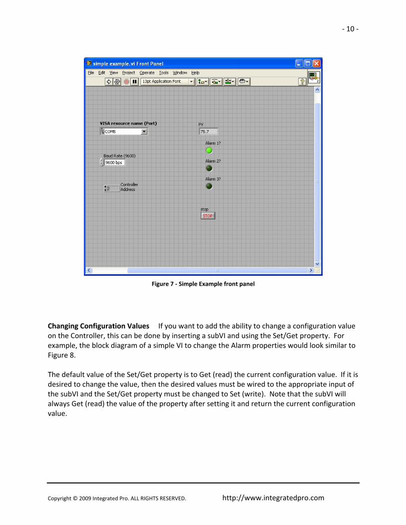
Using the Basic Application VI as a starting point (save it as a new VI if you would like), add a timed loop (found on the Timed Structures subpalette of the Structures palette) to control how often the Alarm LEDs are updated. Leave the default timing values (1000ms update) and don’t forget to add a STOP button control. Also add the subVI Read PV and SV B series.vi from the Data subpalette and wire it in as shown in Figure 6. Your front panel should look similar to Figure 7. Notice that Initialize B series.vi and Close B series.vi are called only at the beginning and end Also notice that the VISA resource and error wires are connected through all the subVIs from left to right and that each individual library VI requires the controller address. If you have multiple controllers on your RS‐485 serial bus, you can call them individually by simply changing the controller address input on the given subVI. Running the VI should cause the PV and Alarm LEDs to update approximately once per second to match the values on the front panel of the Controller.
Figure 6 ‐ Simple Example VI block diagram
Copyright © 2009 Integrated Pro. ALL RIGHTS RESERVED. http://www.integratedpro.com
‐ 10 ‐
Figure 7 ‐ Simple Example front panel
Changing Configuration Values If you want to add the ability to change a configuration value on the Controller, this can be done by inserting a subVI and using the Set/Get property. For example, the block diagram of a simple VI to change the Alarm properties would look similar to Figure 8. The default value of the Set/Get property is to Get (read) the current configuration value. If it is desired to change the value, then the desired values must be wired to the appropriate input of the subVI and the Set/Get property must be changed to Set (write). Note that the subVI will always Get (read) the value of the property after setting it and return the current configuration value.

Copyright © 2009 Integrated Pro. ALL RIGHTS RESERVED. http://www.integratedpro.com
‐ 11 ‐
Figure 8 ‐ Using Set/Get property to read or write configuration values

Copyright © 2009 Integrated Pro. ALL RIGHTS RESERVED. http://www.integratedpro.com
‐ 12 ‐
6. Library Reference Each of the subVIs in the VI library is shown on the VI Tree B series.vi block diagram in Figure 9. The VIs in the library and the VI Tree B series.vi can all be accessed by right‐clicking on the block diagram of a new VI, choosing User Libraries and opening the B series Controller palette as shown before in Figure 1. As shown in Figure 9, the subVIs in the VI library are divided into different categories, approximately indicating their usage in communicating with the Controller. The VIs in the Configuration and Action/Status categories use the Set/Get property to read or write configuration values. The VIs in the Data category are used to read or write data values, such as PV and SV or to read the current value of the Alarms or Output. A brief listing of the functions of each of the subVIs in the library follows. A more detailed description of the input and output parameters for each subVI is contained in the VI documentation for each individual subVI. This can be easily viewed by turning on the LabVIEW context help (the ? button in the upper right of the block diagram window) and hovering with the mouse over each of the subVI icons. A mapping of the correspondence between library VIs and communication register addresses on the B series Controller is given in Table 1.
Figure 9 - VI Tree.vi block diagram showing library subVIs

Copyright © 2009 Integrated Pro. ALL RIGHTS RESERVED. http://www.integratedpro.com
‐ 13 ‐
Initialization VIs
Initialize B series.vi
Call this VI before calling other process controller communications functions, but generally, you need to call the Initialize VI only once at the beginning of an application.
Initializes Serial Communications on given port at chosen baud rate. Returns error if unsuccessful.
Assumes RTU mode communications and uses the following serial port settings: 8bit data, No Parity, 1 Stop bit with Termination Character disabled, with port timeout of 10seconds. Other settings are at default for the platform.
Also stores global Optional Timing Parameters to be used in RS‐485 communications.
Configuration VIs
Set or Get Decimal Place B series.vi
Use this VI to get or set the current analog decimal place setting (SP0, SP1, etc) from the controller (0x1017H). This VI always reads the current property value in addition to setting the property value if desired. Error checking is used ‐ If error input is wired, this VI checks for previous errors and does not execute if error.
IMPORTANT: The actual number of available decimal places varies with the input sensor type (see controller documentation). Some sensors allow for different numbers of decimal places from 0‐3 places.
Older versions of controller firmware may return an error if setting an incorrect decimal place value is attempted. Newer versions may not return an error from the controller if setting an incorrect decimal place value is attempted, however since this VI always reads the number of decimal places after writing, the values can be compared and if an incorrect value has been attempted, the actual value will be different from the attempted value.
Running this VI updates the globally stored value of the decimal point used by Read PV and SV to scale according to decimal point position.
Set or Get Temperature Units B series.vi
Use this VI to get or set the Temperature Unit Display (tPUn) Selection property (0x811). This VI always reads the current property value in addition to setting the property value if desired.

Copyright © 2009 Integrated Pro. ALL RIGHTS RESERVED. http://www.integratedpro.com
‐ 14 ‐
Error checking is used ‐ If error input is wired, this VI checks for previous errors and does not execute if error.
NOTE: Using a "SET" operation will cause a reboot of the device if the units are changed.
Set or Get Heating Cooling Values B series.vi
Use this VI to get or set the Heating or Cooling Parameters. These include: Dual Output parameters: Pb Band (COEF) and Deadband (Dead) (0x100EH ‐ 0x100FH); Hysteresis1 (HtS) and Hysteresis2 (CtS) (0x1010H ‐ 0x1011H); and control cycle periods (HtPd and HCPd) (0x1007H ‐ 0x1008H) (This value is only applicable if control mode is set to PID ‐ see documentation).
This VI always reads the current property value in addition to setting the property value if desired. Error checking is used ‐ If error input is wired, this VI checks for previous errors and does not execute if error.
Set or Get Alarm Configuration B series.vi
Use this VI to get or set the Alarm Upper and Lower Limits (AL1H, etc) (0x1020H ‐ 0x1022H) and Alarm Type (ALA1, ALA2, ALA3) (0x1024H ‐ 0x1029H) (see controller documentation).
Alarm limits are checked against current PV upper and lower limits and an error is returned if they are out of range. If the Alarm type is 0 ‐ disabled, then limits are not written.
This VI always reads the current property value in addition to setting the property value if desired. Error checking is used ‐ If error input is wired, this VI checks for previous errors and does not execute if error.
Set or Get System Alarm Configuration B series.vi
This VI gets or sets the System Alarm (SALA) register value (0x1023H), which determines which of the alarms (AL1, AL2, AL3 is used if a system alarm occurs). See Process Controller documentation. This VI always reads the current contents of the register in addition to writing a new value if desired. Error checking is used ‐ If error input is wired, this VI checks for previous errors and does not execute if error.
Set or Get PV Offset B series.vi
Use this VI to get or set the Process Value (PV) Offset (tPoF) (0x1016H). This value offsets the PV value to match an external reference. (see Controller documentation). This VI always reads the current property value in addition to setting the property value if desired. Error checking is used ‐ If error input is wired, this VI checks for previous errors and does not execute if error.

Copyright © 2009 Integrated Pro. ALL RIGHTS RESERVED. http://www.integratedpro.com
‐ 15 ‐
This VI accesses a globally stored value for the analog decimal place on the controller (or reads it from the controller if the global value has not been stored) and scales the values of PV and SV to set the decimal place accordingly.
Set or Get PV Range Limits B series.vi
Use this VI to get or set the Process Value (PV) Range Upper (tP‐H) and Lower (tP‐L) Limits (0x1002‐0x1003H) (see Controller documentation). This VI always reads the current property value in addition to setting the property value if desired. Error checking is used ‐ If error input is wired, this VI checks for previous errors and does not execute if error.
This VI accesses a globally stored value for the analog decimal place on the controller (or reads it from the controller if the global value has not been stored) and scales the values of PV and SV to set the decimal place accordingly.
The values of PV range limits must be within the range for the input sensor (see Controller documentation). This is NOT checked by this VI.
Set or Get Analog Output Range Limits B series.vi
Use this VI to get or set the Analog Output Range Upper (CrHi) and Lower (CrLo) Limits (0x1014‐0x1015H) These values are only available on devices having an analog output. This VI always reads the current property value in addition to setting the property value if desired. Error checking is used ‐ If error input is wired, this VI checks for previous errors and does not execute if error.
The values of range limits are integer numbers with one unit representing either an increment of output current or an increment of output voltage (for example 1 Unit = 2.8 uA or 1.3mV, see communication register table in Controller documentation for exact value) Values must be within the range for output type and this is NOT checked by this VI (device will return an error message if outside limits).
Set or Get Autotune ON OFF B series.vi
This VI gets or sets the Autotune setting register value (0x813H). This setting is only available if controller is running in PID mode. See Process Controller documentation. This VI always reads the current contents of the register in addition to writing a new value if desired. Error checking is used ‐ If error input is wired, this VI checks for previous errors and does not execute if error.

Copyright © 2009 Integrated Pro. ALL RIGHTS RESERVED. http://www.integratedpro.com
‐ 16 ‐
Set or Get Control Method B series.vi
Use this VI to get or set the Control Method property (0x1005). This VI always reads the current property value in addition to setting the property value if desired. Error checking is used ‐ If error input is wired, this VI checks for previous errors and does not execute if error.
Set or Get PID Group B series.vi
This VI gets or sets the PID Group register value (0x101CH), which determines which of the PID group settings is active if in PID mode. See Process Controller documentation. This VI always reads the current contents of the register in addition to writing a new value if desired. Error checking is used ‐ If error input is wired, this VI checks for previous errors and does not execute if error.
Set or Get SV for PID Group B series.vi
Use this VI to get or set the Set Value (SV0, SV1, etc) register value (0x101DH) associated with the currently selected PID group (PID0, PID1, etc). (see Controller documentation). This VI always reads the current property value in addition to setting the property value if desired. Error checking is used ‐ If error input is wired, this VI checks for previous errors and does not execute if error.
This VI accesses a globally stored value for the analog decimal place on the controller (or reads it from the controller if the global value has not been stored) and scales the value SV to set the decimal place accordingly.
Set or Get PID Values B series.vi
Use this VI to get or set the PID Control parameters (P0,i0,d0,iof0,PdOF0, etc) (0x1009H ‐ 0x100DH) (see controller documentation). Note that the ioF value is always written/read by this VI even if the value of Ti = 0 and the PdoF value is always written/read even if Ti is non‐zero.
This VI always reads the current property value in addition to setting the property value if desired. Error checking is used ‐ If error input is wired, this VI checks for previous errors and does not execute if error.

Copyright © 2009 Integrated Pro. ALL RIGHTS RESERVED. http://www.integratedpro.com
‐ 17 ‐
Action/Status VIs
Set or Get Run Stop B series.vi
This VI gets or sets the Control Run/Stop setting register value (0x814H). If this value is set to Run, the output of the process controller is enabled. This VI always reads the current contents of the register in addition to writing a new value if desired. Error checking is used ‐ If error input is wired, this VI checks for previous errors and does not execute if error.
Set or Get Heating Cooling Mode C series.vi
This VI gets or sets the Heating/Cooling Control mode register value (0x1006H). See Process Controller documentation. This VI always reads the current contents of the register in addition to writing a new value if desired. Error checking is used ‐ If error input is wired, this VI checks for previous errors and does not execute if error.
Get Sensor Type B series.vi
This VI gets the Sensor Type (inPt) register value (0x1004H). See Process Controller documentation for sensor type table and limits. Error checking is used ‐ If error input is wired, this VI checks for previous errors and does not execute if error.
Running this VI updates the globabally stored value of the sensor type used by Read PV and SV to scale according to decimal point position.
Data VIs
Read PV and SV B series.vi
Reads Process Value (PV) and Setpoint Value (SV) from Process Controller. Error checking is used ‐ If error input is wired, this VI checks for previous errors and does not execute if error.
This VI accesses a globally stored value for the analog decimal place on the controller (or reads it from the controller if the global value has not been stored) and scales the values of PV and SV to set the decimal place accordingly.
Write SV B series.vi
Writes Setpoint Value (SV) to Process Controller. This VI checks to make sure the desired SV is within the upper and lower limits on the device and returns an error instead of writing if it is not. Error checking is used ‐ If error input is wired, this VI checks for previous errors and does not execute if error.

Copyright © 2009 Integrated Pro. ALL RIGHTS RESERVED. http://www.integratedpro.com
‐ 18 ‐
This VI accesses a globally stored value for the analog decimal place on the controller (or reads it from the controller if the global value has not been stored) and scales the values of PV and SV to set the decimal place accordingly.
Read Alarm LEDs B series.vi
This reads whether the Alarm LEDs are on or off on the controller from the LED Status Register value (0x102AH). Error checking is used ‐ If error input is wired, this VI checks for previous errors and does not execute if error.
Read Output LEDs and Amounts B series.vi
This reads whether the Output LEDs are on or off on the controller from the LED Status Register value (0x102AH). It also reads the Output amounts in % full scale (0x1012H & 0x1013H). Error checking is used ‐ If error input is wired, this VI checks for previous errors and does not execute if error.
Utility VIs
Check PVSV limits B series.vi
Checks to make sure value is in range of PV limits on device. Returns error if not in range. Use Set or Get PV Range Limits B series.vi to get current device limits
Scale PVSV to Device B series.vi
Scales values to Device range using analog decimal point setting.
Scale PVSV from Device B series.vi
Scales values to Device range using analog decimal point setting.
Get Controller Firmware Version B series.vi
This VI gets the software version register value (0x102FH). See Process Controller documentation. Error checking is used ‐ If error input is wired, this VI checks for previous errors and does not execute if error.
Get Error Status B series.vi
This VI gets the status code register value (0x102EH). See Process Controller documentation. Error checking is used ‐ If error input is wired, this VI checks for previous errors and does not execute if error.

Copyright © 2009 Integrated Pro. ALL RIGHTS RESERVED. http://www.integratedpro.com
‐ 19 ‐
Lock or Unlock panel B series.vi
This VI gets or sets the panel key lock register value (0x102CH) (LOC0,LOC1, etc on device). This VI always reads the current contents of the register in addition to writing a new value if desired. Error checking is used ‐ If error input is wired, this VI checks for previous errors and does not execute if error.
Lock or Unlock Communication Write In B series.vi
This VI gets or sets the Communication Write In lock register value (0x810H). If this value is set, remote communications cannot write in register values to the Controller (except this register). Note that this is not the same thing as Panel Lockout function on the actual device.
This VI always reads the current contents of the register in addition to writing a new value if desired. Error checking is used ‐ If error input is wired, this VI checks for previous errors and does not execute if error.
Close Communication VIs
Close B series.vi
Terminates the software connection to RS‐485 Bus via serial port. Call this VI to make sure the serial port is closed at the end of your application.

Copyright © 2009 Integrated Pro. ALL RIGHTS RESERVED. http://www.integratedpro.com
‐ 20 ‐
Table 1 – B series Controller Communication Register to Library VI Mapping To Read/Write Address(es) Use Library VI (s) 1000H Read PV and SV 1001H Read PV and SV, Write SV 1002H – 1003H Set or Get PV Range Limits 1004H Get Sensor Type 1005H Set or Get Control Method 1006H Set or Get Heating Cooling Mode 1007H – 1008H Set or Get Heating Cooling Values 1009H – 100EH Set or Get PID Values 100FH – 1011H Set or Get Heating Cooling Values 1012H – 1013H Read Output LEDs and Amounts 1014H – 1015H Set or Get Analog Output Range Limits 1016H Set or Get PV Offset 1017H Set or Get Decimal Place 101CH Set or Get PID Group B 101DH Set or Get SV for PID Group 1020H – 1022H Set or Get Alarm Configuration 1023H Set or Get System Alarm Configuration 1024H – 1029H Set or Get Alarm Configuration 102AH Read Alarm LEDs, Read Output LEDs and
Amounts 102CH Lock or Unlock panel 102EH Get Error Status 102FH Get Controller Firmware Version 810H Lock or Unlock Communication Write In 811H Set or Get Temperature Units 813H Set or Get Autotune ON OFF 814H Set or Get Run Stop

Copyright © 2009 Integrated Pro. ALL RIGHTS RESERVED. http://www.integratedpro.com
‐ 21 ‐
Table 2 – B Series Process Controller Menu to Library VI Regulation Mode To Access Value Use Library VI (s) Auto‐tuning (At) Set or Get Autotune ON OFF PID parameters (P0,i0,d0, etc) Set or Get PID Values Hysteresis (HtS, CtS) Set or Get Heating Cooling Values Pb Band, Deadband (COEF, dEAd) Set or Get Heating Cooling Values PV offset (tPoF) Set or Get PV Offset Analog Output Range(CrHi, CrLo) Set or Get Analog Output Range Limits Operation Mode To Access Value Use Library VI (s) Write SV Write SV Run/Stop (r‐S) Set or Get Run Stop Pattern (Ptrn) Unsupported in Base Library Decimal Point (SP Set or Get Decimal Place Alarm limits (AL1H, etc) Set or Get Alarm Configuration Panel Setting Lock (LoC) Lock or Unlock panel Analog Output (oUt 1, etc) Read Output LEDs and Amounts Initial Setting Mode To Access Value Use Library VI (s) Sensor Type (inPt) Get Sensor Type Units (tPUn) Set or Get Temperature Units PV Range Limits (tP‐H, tP – L) Set or Get PV Range Limits Control Mode (CtrL) Set or Get Control Method Ramp/Soak (PAtn) Unsupported in Base Library Heating/Cooling (S‐HC) Set or Get Heating Cooling Mode Alarm Mode (ALA1) Set or Get Alarm Configuration System Alarm (SALA) Set or Get System Alarm Configuration Communication Lock (CoSH) Lock or Unlock Communication Write In (Communications settings not supported)

Copyright © 2009 Integrated Pro. ALL RIGHTS RESERVED. http://www.integratedpro.com
‐ 22 ‐
7. Optional Parameters Optional Timing Parameters Initialize B series.vi is used to open communications between LabVIEW and the RS‐485 bus. It also sets global values for the Optional Timing Parameters to be used in RS‐485 communications. These are values specific to RS‐485 communications that are used throughout the program. They can be modified through an input cluster on the Initialize B series.vi, but unless dictated by such factors as electrical interference on the RS‐485 bus, for instance, it is generally not necessary to change these values:
Max Retries (5): The number of times the program will retry automatically after receiving a serial communication error. Optional write delay (20ms): The modbus specification requires that the RS‐485 serial bus be quiet between transmitted messages. These delays are based on the baud rate. It may be desirable to insert additional delay to account for noise, slow settling, slow device response or other factors. This optional delay is inserted before the required minimum delay, before a message is written. Optional read delay (20ms): (see Optional write delay, above) This optional delay is inserted before the required minimum delay, before a reply is read. Device read timeout (200ms): Specifies how long to wait for a reply from the device before retrying. This delay is a programmatic delay and not the same thing as the VISA serial port timeout, which will return an error in the case of hardware or other failure, and cause the subVI not to retry, but rather to return the error.
All trademarks are property of their respective owners. Usage in this document of trademarks not owned by Integrated Pro is only to facilitate understanding on the part of the reader and no ownership or association is implied. Information furnished by Integrated Pro is believed to be accurate & reliable. No responsibility is assumed, however, by Integrated Pro for its use, whether correct or incorrect; nor can Integrated Pro be held liable for consequences or any infringements of patents or other rights of third parties which may result from its use. Information in this document is current as of date of writing and is subject to change.