b · several components, notably the main pulser and magnet pulser and various gating circuits,...
TRANSCRIPT

- 6 JUJL 1955
PS INTERNAL REPORT
Not for outside distrib_ution
CEHN-PS/HGH6
June 1955
LINAC OOMPON~NTS0 PROVI::JIONAL Sf'l!:CIFICA'I'IONS
No a :5 TI.Ml!'iG E-.:Ul.PME.NT o
The method of inflection into the AoGo P oSo is such that effective
injection ia limited to the period between the moment at which the inflector
electrode voltage is removed, and a moment 60 7 µseCBearlier. We shall call this
the inflection perioda
For normal operation we shall usually wish to inject during the whole
of the infection period, so the ion-source pulse would corweniently be a little
longer (at both ends) than the inflection J.:eriod, mainly to allow for any relative
time error or jitter between them: about 10 or U µsecs ion source pulse, which
gives about 2 µsec margin at each end, would be reasonableo If it turns out that
this 4 µsecs of ueaeless beam is undesirable, then the ion source pulse will
have to be made the same length or a little shorter than the inflection period,
and the time error between them kept down to a fractien of a miorosecondo For
some types of injection studies it will be useful to reduce the injection period
to various values between 1/2 and 6 µaecsp and to place this shorter 'period at
various. times within the inflection perio.d: this will be done by varying the
length (and starting time) of the ion source pulse if this is easily arranged,.
otherwise some form of beamoehopper will be necessary ..
To place the injected beam in the centre of the phase-stable region in
the synchrotrOnp within.± 10 o/o of its heightp the operations above DlllSt occur
at the correct moment of the synchrotron programme within.± 5 µsec* 8 eo the
relative timing of ion source, inflector, beam chopper if ariy,, between oneanother
has to be more pre<~iae than their "absolute" timing as a whole from the- synchrotrono
It is therefore prC>posed to deI'ive a pulse from the symchrot_ron R .. F~ frequency by
* we are assuming B :; 12 K8/sec and operation on the 20th ha~onico
- 2 - CERN ... PS/HGH 6
an Fl type device (see CERN-PS/RGb 7 and CERN-PS/HGH 5) about 20 µsecs
before the ideal instant of injection, and to hive a variable delay unit
of 5 to ~O µsec range, Oo2 µsec precision, between the F1
device and each
of the ion source, inflector, and b_eam chopper if any. The F1
device should
have its resonant~ frequency adjustable over a range of± 6 per mil (corres
ponding to .± 70 µsec variation in injection timing) to allow full exploration
of the phase stable region in the synchrotronQ An F1
_device at a fiJCed,
lower resonant frequency, followed by a 0°140 µsec adjustable delay, could be
used instead, but this is not so good a solution.
Several components, notably the main pulser and magnet pulser and
various gating circuits, require to be triggered at ~imes of the order of
200 µsec before the inflection period. For this purpose it is proposed to
have another F1
device (.~'l) which provides a pulse 250 µsec before the one
already required (F1
), by virtue of having a 2.1 o/o lower resonant frequency.
and then a number of 5-250 µsec range variable delay units, one for eac4 of
these pulses, gates etco The variation in timing required in F1
for explora ..
tion purposes must also occur in Fi, ioea they must be gang-tuned over.± 6
per mil range of frequenoya
F1 units with the sort of precision we require are being developed
for the purpose of checking the a.ccurracy of the synchrotron frequency-computeri
so it is likely that the linac group can make its requirements of F1 units
without doing much development worko
To obt8.in a system of maximum flexibility the output pulses of the
two F1 units, the input pulses required by, and the output pulses given by,
the delay units of both kinds, should all be the sameo Unless new technical
considerations appear, we can standardise on the· triangular pulse of
CERN-PS/EE 3o All modulators, gates etca should then be· built to respond to
.. By resonant frequency we mean the Rol<\. frequencii at the instant when the device produces its output :pulse, so the effect of any intrinsie time l~ is includedo

·~ 3 - CElllkPS/HGH 6
~uch pulsesp containing where necessary their own preamplifiers or
electronic relays to do soo
'rhe two gauged Fl units and the collection of short and long
~ariable delay units already described cover the basic requirements of
linac tirnine equipment: their specifications are given in Appendix Io
Various other requirements which arise are dealt with belowu
Simulator.
To set up or test the linac when the synchrotron is not operating
we need a unit to simulate F1
and Flo This oan conveniently have a variable
repetition rateo
l!iterpulser.
We shall want the facility to operate tlie linac at a faster repetition
rate thrur the synchrotron, for example: linac at 1 pulse per second with every
fllth pulse being injected into the 1 pulse per 5 second synchrotrona Thus a
unit is required that behaves~ between synchrotron pulses, like the simulator
already mentioned~ and it will probably be convenient to make a single unit
which will do either job., When running the synchrotron at very much reduced
repetition ratep or on a single-shot basis~ this unit would be set to run on
from one synchrotro.n pulse indefinitely until blocked by a signal warning it
of the imminence of the next a
When using this inferpulser to rwi the linac faster than the synchrotron
some components (e.g. the RoF. system)will be required to operate on every
pulse, but some others (e.g~ ion source, inflector, :re:rhar:s pulsed focusing)
may only be required on the pulses at which the synchrotron is operatingo This
is easily arranged by connecting the delay""Wli ts for the former to the
interpulser and the delay units for the latter to the F1
or F). unit.
- 4 - CERN-PS/HGH 6
Ch!ickingo
Most of the checking of this timing equipment will be done by
t~iggering a scope time=base from Fl' or F] and putting any or all of
the outputs of the delayi units on~o the Y pla4les. The scope should have
at least a 30 and a 300 µse~ sweep time availableo The time differen~e
between the Fi and the F1
pulse should be checked (to check both the gaG:.:,ai.ng
and the synchrotron frequency law in this interval) by having an additional t
long-delay unit triggered by Fi and set alilfays at 250 µsecs delay.. F1
should
probably be checked by having another similar unit Fl , not ~unable and more
stable than F1
and Fi" , giving a signal at the centre of the nominal range of
F1 , or (probably more usefully) at the centre of the ideal inflection period.
A .general check on the delay units. done when the components that they
trigger are slritched off, can be made more speedy and convenient by o~rating
the simulator at say 10 or 100 pulses per second .. I:f such a :facility is pro..;
vided it must he made safe against false moves by designing all m?dulatora
etc in such a way that they neither suffer nor do any harm when triggered at
a high rateo
Machine Parameters.
All the above, and Appendix I, are based on the assumptions that we
use a harmonic number of 20 and a rate-of-rise of 12 '1\gausa/seca An appendix
will be issued to deal w,ith the· effect of changing these parameters if such
a change seems likely. 0
The effects of small differences in B from ~ a- . nominal 12 Kgauss/S<ic
are as follows:
CERN"'·PS/HGH 6
u
l o If the difference between Band its nominal figure exceeds about 10 o/o
the resonant-frequency difference between F1 and Fl ought to be altered
by retuning the lattero
" 2 o An error or a change in B8 less than 10 o/ o, can readily be dealt with
by operating the ordinary control knobs (checking against F'}) 0
3o Changes in B~ even including erratic ones from pulse to pulse, can be
ignored if they do not exceed about l o/o u
If there is an error in the synchrotron frequency computer the
above remarks about B can in principle be applied to errors in &; It is very
unlikely that such errors can be large enough to matter in the present connexion
because the computer must generate the correct q,.,1, at injection a.lid subsequentlyp
within a few parts i;er mil or betterp for other reasons : so we can be reasonably
certain that ~ will, already in the last few hundred microseconds before in .. 6 .
jectionp have the correct relationship to B within l 0/06
GGRN·~PS/HGH 6
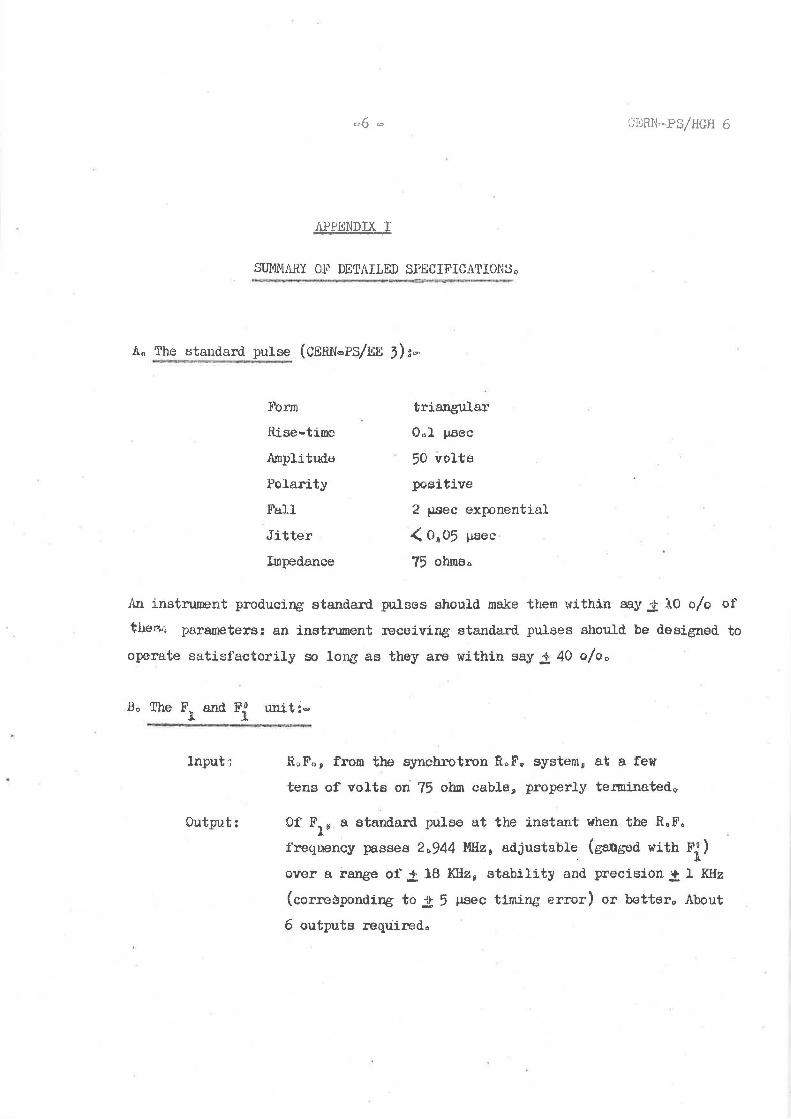
11.Pf'I!:NDIX I
~!ii.HY 01<' DETAILED SPECIFICATIONSo
An The standard pulse ( CERN ... PS/EE 3) : ....
Form triangular
Rise-time Oal µsec
Amplitude 50 volts Polarity poaitive
Fall 2 !J.SeC exponential
Jitter .( 0~05 µsec
Impedance 75 ohms,,
An instrument producing standard. pulses should make them within say.! lO o/o of
tlte::-...-; parameters: an instrument receiving standard pulses should be designed to
operate satisfactorily so long as they are within say.± 40 o/oo
Input·;
Output:
R~Fo, from the synchrotron RoFo system 0 at a few
tens of volts ori 75 ohm cable, properly tenninated~
Of F1 ~ a standard pulse at the instant when the R.F.
i'requency passes 2 .. 944 MHz& adjustable. (ganged with F).)
over a range of.± 18 KHz, stabilit~ and precision.± l KHz
(corresponding to jt 5 µsec timing error) or better., About
6 outputs requiredo
CERNoPS/HGH 6
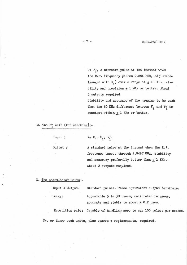
Of Fie a standard pulse at the ins~ant when
the RaFa frequency passes 2a884 MHz, adjustable
(ganged with F1
) over a range of.± 18 KHz, sta
bility and precision.± 1 I<Rz or better. About
6 outputs required
Stability and accuracy of the ganging to be such
that the 60 KHz difference between F1
and Fi is
constant within± 1 KHz or bettero
CQ 'l'he ·Fl unit (for checking,): ....
Input ~
Output :
Do The short•delay upits:~
Input +Output;
Delay:
A standard pulse at the instant when the H.F.
frequency passes through 2a9497 MHz, stability
and accuracy preferably better than.± l KHzo
About 2 outputs requiredc
Standard pulses. Three equivalent output tenninalso
Adjustable 5 to 30 µsecs, calibrated in µsecs~
accurate and stable to about ,:t 0.2 µseo •
.Repetition rate= Capable of handling zero to say 100 pulses per second o
Two or three such units., plus spares + replacements, rf;}quiredo
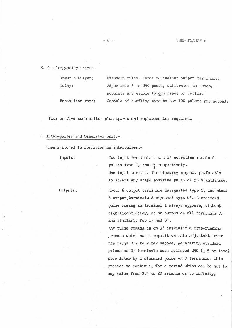
Eo The lop.g-delay units:o
Inp~t -+Output:
De.lay:
Hepetition rate:
CEHN·--PS/HGH 6
Standard pules. Three equivalent output tenninals 0
Adjustable 5 to 250 µ.secs, calibrated in µsecsf
accurate and stable to ~ 5 µsecs or better.
Capable of handling zero to say 100 pulses per second 0
Four or five such units, plus spares and replacements, required.
F~ Inter-pulser and Simulator unit:~
When switcl1ed to operation as interpulser:=
Inputs:'
Outputs:
'l'wo input terminals I and l ~ accepting standard
pulses from F, and F{ respectively~
One input terminal for blocking signal, preferably
to accept any shape positive pulse of 50 V amplitudea
About 6 output tenninals designated type o. and about
6 output.tenninala designated type 0°o A standard
pulse coming in terminal I always appears, without.
significant delay, as an output on all tenninals o, · and sirnil~rly for I" and Ogo
Any pulse coming in on 1 9 initiates a free-running
process which has a repetition rate adjustable over
the range Ool to 2 per second, generating standard
pulses on 0' tenninals each followed 250 (t 5 or less)
µsec later by a standard pulse on 0 terminalso Thia
process to continue, for a period which can be set to
any value from Oa5 to 20 seconds or to infinityv
CE:fil.l.,,ps/HGH 6
unless and until stopped by a signal appearirJg on the
blocking-signal input terminalo
When switched to operation as simulator:
Inputs:
Outputs:
None o 'rhere 'should be no effect on operation or output
eyen if the input tenninals remain connected and pulses
are fed into themo
The same terminals are used as for use as an. interpulser0
and the free-~ng process is also just the same as
for interpuls1:r use except that a manual control (switch ·
or push·buttona) is U$0d to initiate it and to block i~o
To have a nigher (,_ 100/sec) repetition rate available
may be conv~niento
HoGoHerewardo