b2 Φb2 =m21imccutche/phys153_lec/lecture14...if the current in coil 1 varies, there will be an...
TRANSCRIPT

Inductance
Fig. 30.3
What difference does a coil of wire make in
a circuit? In a d.c. circuit, there is no difference
between a coil and a straight wire. But in an a.c.
circuit, a coil of wire makes a big difference, with
changing currents, and induced emfs.
A changing current in one coil can induce an emf
in another coil (as in the figure). The coupling between
two coils is described by mutual inductance.
coil 1
coil 2
PHYS 153 08W 1PHYS 153 08W 1PHYS 153 08W 1
Consider the two coils shown. The black coil is coil 1, and the blue coil is
coil 2.
Denote time varying quantities with lower case letters.
Current creates a magnetic field in coil 1, and some of this flux (or all of it
in this case) passes through coil 2. Denote this flux, per turn, . 1i
2BΦ
12 iB ∝Φ
1PHYS 153 08W
or 12122 iMN B =Φ
21M is the mutual inductance between the two coils.1
2221
i
NM BΦ
=

dt
diM
dt
dN B 1
212
2 =Φ
∴
Since dt
dN B222
Φ−=ε
dt
diM 1
212 −=∴ε
21M depends on the geometry of the two coils.
Starting with coil 2, and considering the interaction with coil 1, we should
use as the mutual inductance. But the interaction between the two 12M
PHYS 153 08W 2PHYS 153 08W 2PHYS 153 08W 2PHYS 153 08W 2
use as the mutual inductance. But the interaction between the two
coils is the same whether you put a changing current through coil 1, or a
changing current through coil 2.
12M
2
11
1
222112
i
N
i
NMMM BB Φ
=Φ
===
Reciprocal relationships hold.
dt
diM 1
2 −=ε and dt
diM 2
1 −=ε
(unit is the henry, H)
1 H = 1Wb/A = 1 V.s/A

If the current in coil 1 varies, there will be an induced emf in coil 1 as well (and
only coil 1 if there is no coil 2). This is a self-induced emf, and by Lenz’s law,
will always oppose the change that caused it.
We define self-inductance by i
NL BΦ= (units are the same, henry, or H)
From this, we can see that
dt
diL
dt
dN B =
Φ
diL−=ε
PHYS 153 08W 3PHYS 153 08W 3PHYS 153 08W 3PHYS 153 08W 3
The induced emf dt
diL−=ε
Note that the equations for self-inductance have the same form as those
for mutual inductance.
Because of this opposition for changes to the current, an inductor (or
choke as it is sometimes called) has resistance in an a.c. circuit. It can
also act with a resistor to cause resonance at a particular frequency in
a circuit. This is the principle behind being able to tune a radio to a
specific frequency, or radio station.

Fig. 30.11
Here is an example of an RL −circuit. When S1 is open, there is no
current. Just after S1 is closed, the
current is still zero. But there is a back
emf in the inductor. A short
time after the switch is closed, there is
a current in the circuit and a potential
dtdiL
iRdrop across the resistor.
Applying Kirchoff’s loop rule, (S2 always open)
PHYS 153 08W 4PHYS 153 08W 4PHYS 153 08W 4
Applying Kirchoff’s loop rule,
0=−−dt
diLiRε
Fig. 30.8
Self-inductance of a toroid.
Assume that B is uniform across the cross-
section.
r
NiABAB π
µ2
0==Φ

The flux is the same through each turn, and there are turns. BΦ N
r
AN
i
NL B
πµ2
2
0=Φ
=∴
For turns, 500=N20.4 cmA = , and cmr 5.7=
HL µ267=
If the current increased from 0 to 4.0 A in 2.0 sµ
||||di
L=ε
PHYS 153 08W 5PHYS 153 08W 5PHYS 153 08W 5
||||dt
diL=ε = 533.3 V opposing the current increase.
Inductance of a solenoid
Assume that is uniform inside and zero outside the solenoid.
The solenoid has turns, cross-sectional area , and length .
→
BN A l
il
NniB 00 µµ ==
l
NiAB
0µ=Φ
l
AN
l
NiA
i
N
i
NL oB
2
0µµ==
Φ=∴

Problem 30.44
A coil has 400 turns and an inductance of 3.50 mH. The current in the coil
varies with time according to
).0250.0
cos()680(s
tmAi π=
(a) What is the maximum emf induced in the coil?
(b) What is the maximum average flux through each turn of the coil?
(c) At t = 0.0180 s, what is the magnitude of the induced emf?
PHYS 153 08W 6PHYS 153 08W 6PHYS 153 08W 6

Energy stored in an inductor
Fig. 24.2
Fig. 28.24
→
B
PHYS 153 08W 7PHYS 153 08W 7PHYS 153 08W 7
Recall that it took work to charge a capacitor. It took no work to place the first
charge, and the most work to place the last charge. What happened to all the
work that was done? It went into establishing an electric field.
The work done, or the energy stored was calculated to be
QVCVC
QU
2
1
2
1
2
22
===
This energy was recovered when the capacitor was discharged.
Similar ideas apply to an inductor as well.
The energy density 2
02
1
.E
volUu ε==

If the current in an inductor, , is increasing at the rate , there will be
opposition to further current flowing into the conductor. i dt
di
Assuming that the resistance of the windings is zero, the voltage between
the terminals a and b is
R
dt
diLVab =
The rate P, at which at which energy is being delivered to the inductor (equal
to the instantaneous power supplied by the external source) is
diLiiVP ==
PHYS 153 08W 8PHYS 153 08W 8PHYS 153 08W 8
dtLiiVP ab ==
During a time , the energy supplied is dt LidiPdtdU ==
Hence the total energy supplied in building up to a final current is
2
0 2
1LIidiLU
I
∫ ==
I
This work done, or energy supplied, goes into establishing a magnetic field.
To develop these ideas further, consider a toroidal solenoid (toroid). Here
the magnetic field is completely contained, with no fringing effects at the end.

The self inductance , and so for a toroid, r
ANL
πµ2
2
0=
r
AINLIU
πµ22
1
2
1 22
02 ==
The magnetic energy density is
2
22
0)2(2
1
2. r
IN
rA
U
vol
Uu
πµ
π===
Recall for a solenoid, r
NIB
πµ2
0=
2B
PHYS 153 08W 9PHYS 153 08W 9PHYS 153 08W 9
0
2
2µB
u =∴ (magnetic energy density in a vacuum)
or µ2
2Bu = (magnetic energy density in some material)
Note the similarity in form to the energy density stored in an electric field.
Even though we relied on the special case of a toroid, this expression is valid
in general.

Fig. 20.5 Fig. 30.10
Recall way back in the study of thermodynamics, --the Otto cycle.
PHYS 153 08W 10PHYS 153 08W 10PHYS 153 08W 10
At the beginning of the adiabatic expansion (the power stroke), the gas was
compressed and the spark plug fired.
There is a primary coil connected to the battery, which produces a strong
magnetic field. A secondary coil with about 100 x as many turns is wound
around the primary. At the instant the plug is required to fire, the current to the
primary is interrupted. This produces an emf of tens of thousands of volts in
the secondary coil, which is connected across the spark plug, causing a spark.
This energy comes from the stored magnetic field.

R-L circuit
We have already had a brief look at this back in slide 4.
Let’s now look at current growth ( charging) and current decay
( discharging).≈
≈A simple circuit with an R and L is
shown.
Why is the switch S2 included?
At instant that S1 is closed, 0=i
PHYS 153 08W 11PHYS 153 08W 11PHYS 153 08W 11
Fig. 30.11
At instant that S1 is closed,
and all of the voltage drop is across
L. When current starts flowing, there
will be a voltage drop across R as
well.
0=i
0=−−dt
diLiRε
L
iR
dt
di −=ε

At ,0=t ,0=i and Ldt
dit
ε==0)(
,∞=t ,Ii = ,0)( =∞=tdt
di
RI
ε=
What about the time between the initial and final
times (the time between and 0=t∞=t )?
Fig. 30.12 shows increasing with time.)(ti
PHYS 153 08W 12PHYS 153 08W 12
Fig. 30.12
Fig. 30.12 shows increasing with time.)(ti
L
dt
iR
di=
−εdt
L
R
Ri
di−=
−ε
'
00 '
'
dtL
R
Ri
di ti
∫∫ −=−ε

tL
R
R
Ri
−=−
−)ln(
ε
εt
LR
e
R
Ri
)(−
=−
−
ε
ε
)1()( t
LR
eR
i−
−=∴ε
( growth in an inductor))(ti
L=τ is the time constant. When ,
Lt = I
eIti 63.0)11()( ≈−=
PHYS 153 08W 13PHYS 153 08W 13
R
L=τ is the time constant. When ,
R
Lt = I
eIti 63.0)11()( ≈−=
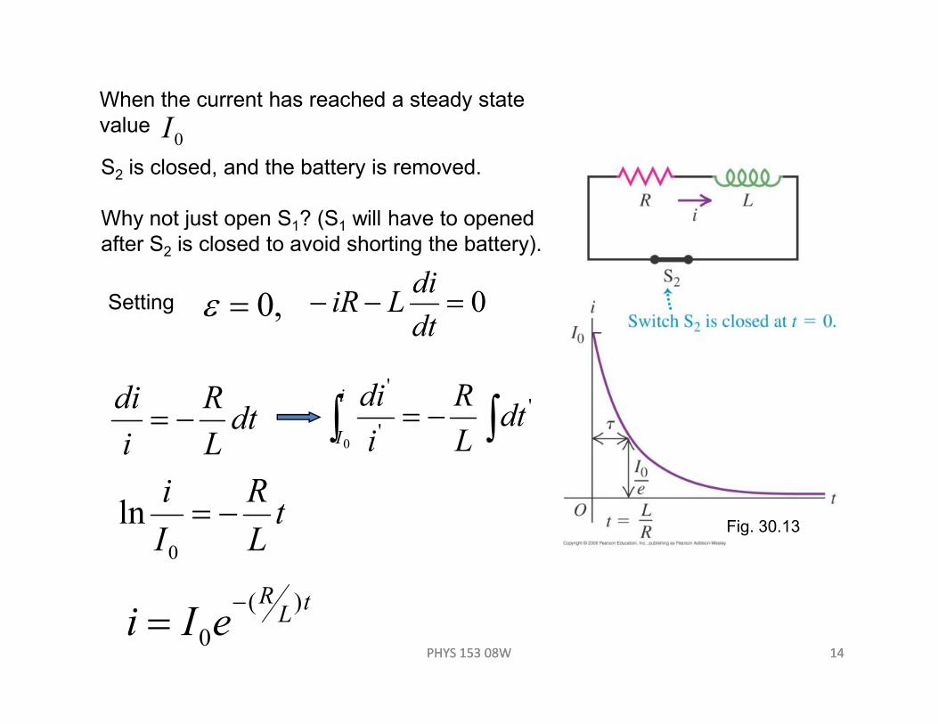
S2 is closed, and the battery is removed.
Why not just open S1? (S1 will have to opened
after S2 is closed to avoid shorting the battery).
When the current has reached a steady state
value 0I
Setting ,0=ε 0=−−dt
diLiR
PHYS 153 08W 14PHYS 153 08W 14
Fig. 30.13
dtL
R
i
di−= ∫∫ −= '
'
'
0
dtL
R
i
dii
I
tL
R
I
i−=
0
ln
tL
R
eIi)(
0
−=

L-C circuit
PHYS 153 08W 15PHYS 153 08W 15
Notice how this circuit behaves very differently from the R-C, or the R-L
circuits. Here there is no exponential growth, or decay. When the switch
is closed, the charge on the fully charged capacitor begins to decay, and
current flows in the circuit. The energy that was stored in the electric field
of the capacitor transfers to energy being stored in the magnetic field of
the inductor.

After , the magnetic flux is a maximum, the the magnetic field
begins to decay. The charge on the capacitor begins to build up with the
opposite polarity. This energy exchange oscillates back and forth. For an
ideal circuit (i.e. no reistance), there is no energy dissipation and the stored
energy oscillates back and forth between the capacitor and the inductor
indefinitely
Of what kind of a system, that we have studied, does this remind you?Answer: undamped SHM.
0=Φ
dt
d B
Suppose at a certain time the charge on the capacitor is discharging, so
(see text for more in-depth discussion).
PHYS 153 08W 16
Suppose at a certain time the charge on the capacitor is discharging, so
.0<dt
dqThen using Kirchhoff’s loop rule,
.0=−−dt
diL
C
q
dt
dqi =Since , then 0
12
2
=+ qLCdt
qd

Indeed, this equation has the same form as
the equation for undamped SHM.
02
2
=+ xm
k
dt
xd
Note the analogies.
xq⇔ xvi⇔
mL⇔ k⇔1
PHYS 153 08W 17
mL⇔ kC⇔1
.AQ⇔
This makes it easy to set up equations, and
to define parameters for the oscillating circuit.
(see Table 30.1)

L-R-C series circuit
What was the analysis that followed undamed SHM? Damped SHM.
Adding a resistor to the L-C circuit damps the oscillating current.
With a resistor in the circuit, Kirchhoff’s loop rule becomes,
0=−−−C
q
dt
diLiR
Replacing with and rearranging, we get idt
dq
PHYS 153 08W 18
Replacing with and rearranging, we get idt
01
2
2
=++ qLCdt
dq
L
R
dt
qd
For a solution, use the analogy to damped SHM.
02
2
=++ xm
k
dt
dx
m
b
dt
xd

Which has the solution (for )
)cos( ')2
(φω +=
−tAex
tm
b
where 2
2'
4m
b
m
k−=ω
Borrowing from this, the solution to the damped oscillatory circuit is,
kmb 42 <
This is underdamped SHM.
PHYS 153 08W 19
Borrowing from this, the solution to the damped oscillatory circuit is,
])4
1cos[(
2
2)
2(
φ+−=−
tL
R
LCAeq
tL
R
and 2
2'
4
1
L
R
LC−=ω
(for )
C
LR
42 <
(underdamped series circuit)CRL −−
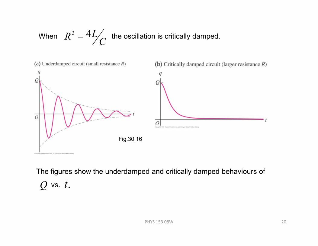
When the oscillation is critically damped. C
LR 42 =
PHYS 153 08W 20
The figures show the underdamped and critically damped behaviours of
Q vs. .t
Fig.30.16

Problem 30.65
Fig. 30.25
In the circuit shown, switch
S is closed at time t = 0.
(a) Find the reading of each
meter just after S is closed.
(b) What does each meter
read long after S is closed?
PHYS 153 08W 21

Problem 30.72
In the circuit shown, neither
the battery nor the inductors
have any appreciable
resistance, the capacitors are
initially uncharged, and the
switch S has been in position
1 for a long time.
(a) What is the current in the
circuit?
PHYS 153 08W 22
circuit?
(b) The switch S is now suddenly
flipped to position 2. Find the maximum
charge that each capacitor will receive,
and how much time after the switch is
flipped that it will take them to acquire this charge.
Fig. 30.30