b200 screw compressors
TRANSCRIPT
INSTRUCTIONS 1401-X00 e
Section 1401
Effective June 2010
Replaces May 2010
Original instructions
B200 SCREW COMPRESSORS
INSTALLATIONOPERATION
MAINTENANCESAFETY
STORAGE
Your distributor :
Z.I. La Plaine des Isles - F 89000 AUXERRE - FRANCE
Tel. : +33 (0)3.86.49.86.30 - Fax : +33 (0)3.86.49.87.17
[email protected] - www.mouvex.com
12R/10L PF12R/10L PS
12R/10L HY
2/17NT 1401-X00 06.10 B200 e
MOUVEX TRUCK SCREW COMPRESSORSAFETY, STORAGE, INSTALLATION, OPERATION AND MAINTENANCE INSTRUCTIONS
MODEL : B200
REMARKS :
MOUVEX truck screw-type compressors MUST be installed in sys-
tems designed by qualified personnel. The installation MUST be in
compliance with local standards, national regulations and rules of
safety.
This manual is designed to permit installation and commis-
sioning of MOUVEX truck screw-type compressors and MUST
accompany the compressor.
Maintenance of MOUVEX screw-type compressors must ONLY
be carried out by qualified technicians. This maintenance must
meet local and national standards as well as all safety regula-
tions. Read this manual, including all instructions and warn-
ings, in full BEFORE any use of MOUVEX compressors.
Do not remove the warning and use label stickers that are
found on the compressors.
This is a SAFETY ALERT SYMBOL
When you see this symbol on the product, or in the manual, look
for one of the following signal words and be alert to the potential for
personal injury, death or major property damage.
Warns of hazards that WILL cause serious personal injury,
death or major property damage
Warns of hazards that CAN cause serious personal injury,
death or major property damage.
Warns of hazards that CAN cause personal injury or property
damage.
NOTICE
Indicates special instructions which are very important and
must be followed.
SAFETY INFORMATIONS
WARNING
CAUTION
DANGER
1. OVERALL DIMENSIONS . . . . . . . . . . . . . . . . . . . . . . . . . .4
2. GENERAL DATA . . . . . . . . . . . . . . . . . . . . . . . . . . . . . . . .62.1 Principle of operation . . . . . . . . . . . . . . . . . . . . . . . . . .6
2.2 Technical characteristics . . . . . . . . . . . . . . . . . . . . . . . .6
2.3 Operating ranges . . . . . . . . . . . . . . . . . . . . . . . . . . . . .7
3. INSTALLATION . . . . . . . . . . . . . . . . . . . . . . . . . . . . . . . . .73.1 B200 PF with truck power take-off . . . . . . . . . . . . . . . .7
3.2 B200 PS with drive shaft . . . . . . . . . . . . . . . . . . . . . .10
3.3 B200 HY with hydraulic motor . . . . . . . . . . . . . . . . . . .11
3.4 Piping . . . . . . . . . . . . . . . . . . . . . . . . . . . . . . . . . . . . .11
4. USE OF COMPRESSOR . . . . . . . . . . . . . . . . . . . . . . . . . .134.1 Lubricant recommendations . . . . . . . . . . . . . . . . . . . .13
4.2 Filling of lubricant . . . . . . . . . . . . . . . . . . . . . . . . . . . .13
4.3 Operation . . . . . . . . . . . . . . . . . . . . . . . . . . . . . . . . . .13
4.4 Starting-up . . . . . . . . . . . . . . . . . . . . . . . . . . . . . . . . . .13
5. MAINTENANCE . . . . . . . . . . . . . . . . . . . . . . . . . . . . . . . .145.1 Maintenance schedules . . . . . . . . . . . . . . . . . . . . . . .14
5.2 Compressor oil change procedure . . . . . . . . . . . . . . .14
5.3 Inlet shaft replacement . . . . . . . . . . . . . . . . . . . . . . . .14
5.4 Warranty claims . . . . . . . . . . . . . . . . . . . . . . . . . . . . .15
6. STORAGE CONDITIONS . . . . . . . . . . . . . . . . . . . . . . . . .156.1 Compressor . . . . . . . . . . . . . . . . . . . . . . . . . . . . . . . .15
6.2 BSC oil . . . . . . . . . . . . . . . . . . . . . . . . . . . . . . . . . . . .15
7. SCRAPPING . . . . . . . . . . . . . . . . . . . . . . . . . . . . . . . . . .15
8. COMPRESSORS FORM INFORMATION . . . . . . . . . . . . .16
9. CERTIFICATE OF CONFORMITY . . . . . . . . . . . . . . . . . .17
TABLE OF CONTENTS Page
ADDITIONAL DOCUMENTATION
The table below gives the list of instructions in addition
to this central instruction :
B200
applicationInstructions
Spare parts
list
12R/10L NT 1401-X00 PL 1401-X01
SAFETY CHECK LIST1. Before operating the compressor, ensure the vessel to which the
compressor is connected is certified to withstand the pressure and
/or vacuum produced.
2. Verify adequately sized relief valves have been fitted to protect the
vessel. Do not use solvents or inflammable products for cleaning
the pipelines and the accessories.
3. Gas/air mixtures which are potentially volatile/explosive must not be
introduced or allowed to be introduced into the compressor.
4. All pressure vessel and piping connected to the compressor must
be isolated and in a safe operating condition.
5. Operators should wear ear protection when operating truck mount-
ed compressors.
6. There are components within the compressor of sufficient weight
to cause injury if mishandled. Use proper lifting devices as neces-
sary.
7. Where necessary, this equipment should be grounded to control
static electricity.
8. The temperature of the air leaving the compressor is elevated
above ambient due to air compression. Check that the elevated
temperatures do not adversely affect the product and any material
used in design of the system. Attach clearly marked warning signs
to warn of potentially hot surfaces on the compressor, piping and
accessories which will burn if touched.
9. Mounting of the compressor must be correctly engineered and the
compressor must be properly secured. Refer to the Compressor
Mounting section of this manual.
NOTICE :MOUVEX COMPRESSORS ARE NOT DESIGNED FOR HANDLING
LIQUID, POWDER OR CONDENSATE. TO DO SO WILL VOID THE
WARRANTY.
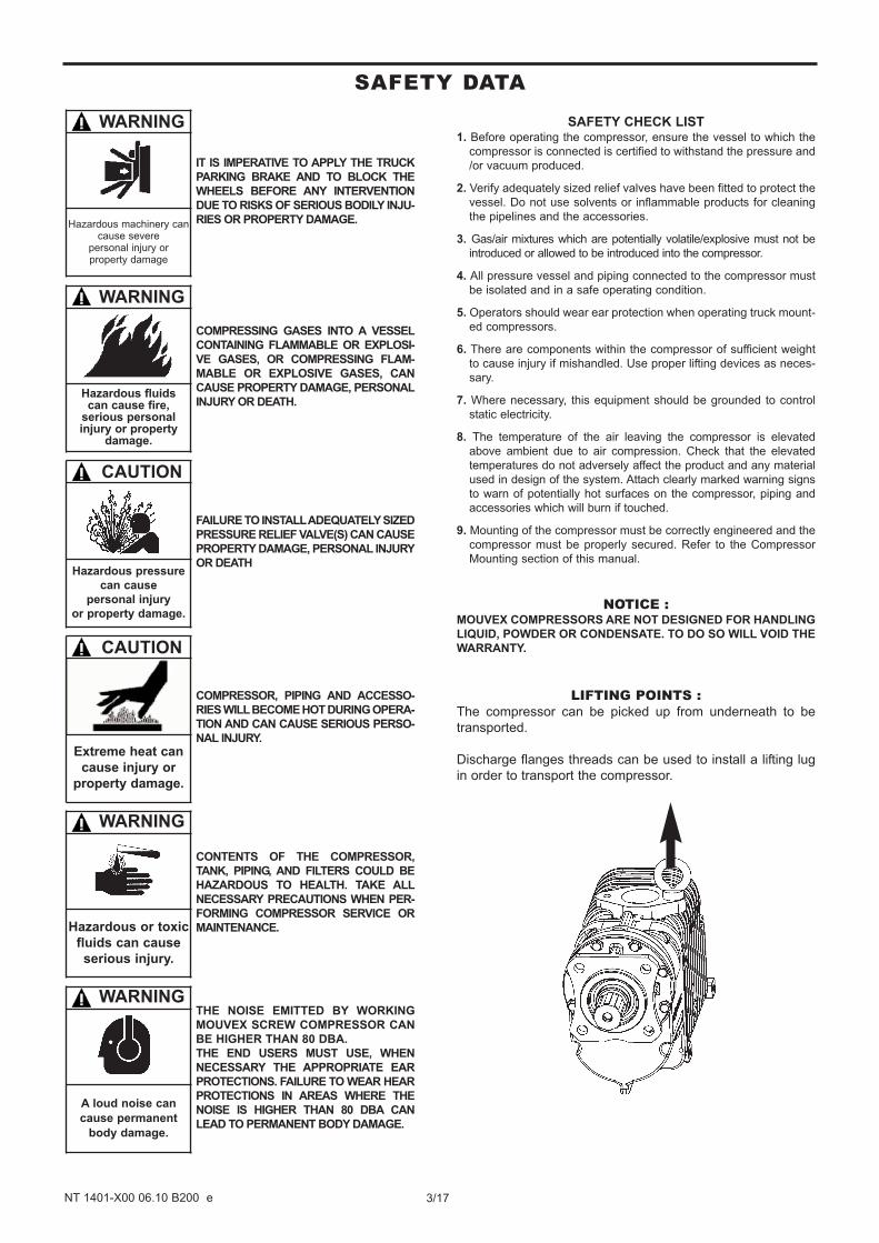
LIFTING POINTS :The compressor can be picked up from underneath to be
transported.
Discharge flanges threads can be used to install a lifting lug
in order to transport the compressor.
THE NOISE EMITTED BY WORKING
MOUVEX SCREW COMPRESSOR CAN
BE HIGHER THAN 80 DBA.
THE END USERS MUST USE, WHEN
NECESSARY THE APPROPRIATE EAR
PROTECTIONS. FAILURE TO WEAR HEAR
PROTECTIONS IN AREAS WHERE THE
NOISE IS HIGHER THAN 80 DBA CAN
LEAD TO PERMANENT BODY DAMAGE.
WARNING
A loud noise can
cause permanent
body damage.
CONTENTS OF THE COMPRESSOR,
TANK, PIPING, AND FILTERS COULD BE
HAZARDOUS TO HEALTH. TAKE ALL
NECESSARY PRECAUTIONS WHEN PER-
FORMING COMPRESSOR SERVICE OR
MAINTENANCE.
WARNING
Hazardous or toxic
fluids can cause
serious injury.
COMPRESSOR, PIPING AND ACCESSO-
RIES WILL BECOME HOT DURING OPERA-
TION AND CAN CAUSE SERIOUS PERSO-
NAL INJURY.
CAUTION
Extreme heat can
cause injury or
property damage.
FAILURE TO INSTALL ADEQUATELY SIZED
PRESSURE RELIEF VALVE(S) CAN CAUSE
PROPERTY DAMAGE, PERSONAL INJURY
OR DEATH
CAUTION
Hazardous pressure
can cause
personal injury
or property damage.
COMPRESSING GASES INTO A VESSEL
CONTAINING FLAMMABLE OR EXPLOSI-
VE GASES, OR COMPRESSING FLAM-
MABLE OR EXPLOSIVE GASES, CAN
CAUSE PROPERTY DAMAGE, PERSONAL
INJURY OR DEATH.
WARNING
Hazardous fluids can cause fire,
serious personal injury or property
damage.
IT IS IMPERATIVE TO APPLY THE TRUCK
PARKING BRAKE AND TO BLOCK THE
WHEELS BEFORE ANY INTERVENTION
DUE TO RISKS OF SERIOUS BODILY INJU-
RIES OR PROPERTY DAMAGE.
WARNING
Hazardous machinery cancause severe
personal injury or property damage
3/17NT 1401-X00 06.10 B200 e
SAFETY DATA
4/17NT 1401-X00 06.10 B200 e
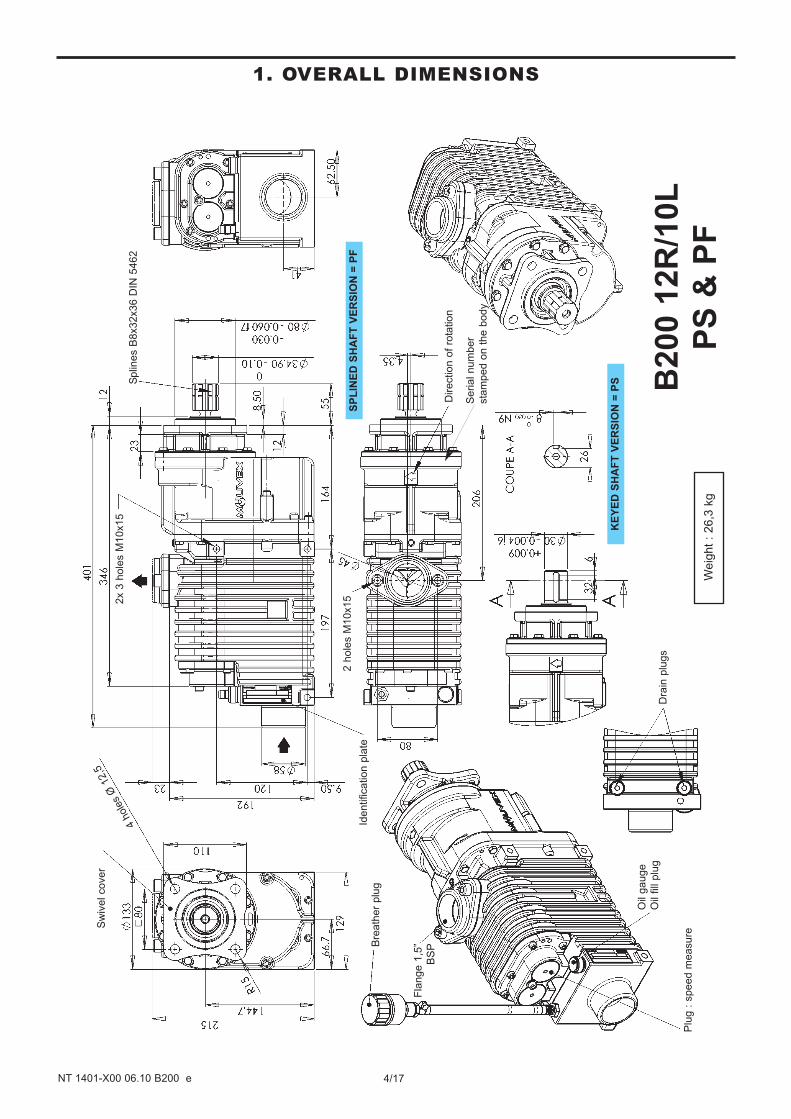
1. OVERALL DIMENSIONS
Identification p
late
4 h
ole
s Ø
12,5
Sw
ivel cover
Dra
in p
lugs
Bre
ath
er
plu
g
Plu
g :
speed m
ea
sure
Oil
gauge
Oil
fill
plu
g
Fla
nge 1
,5”
BS
P
Splin
es B
8x32x36 D
IN 5
462
2 h
ole
s M
10x152x 3
hole
s M
10x15
Direction o
f ro
tation
SP
LIN
ED
SH
AF
T V
ER
SIO
N =
PF
KE
YE
D S
HA
FT
VE
RS
ION
= P
S B200 1
2R
/10L
PS
& P
FW
eig
ht
: 26,3
kg
Serial num
ber
sta
mped o
n t
he b
ody
5/17NT 1401-X00 06.10 B200 e
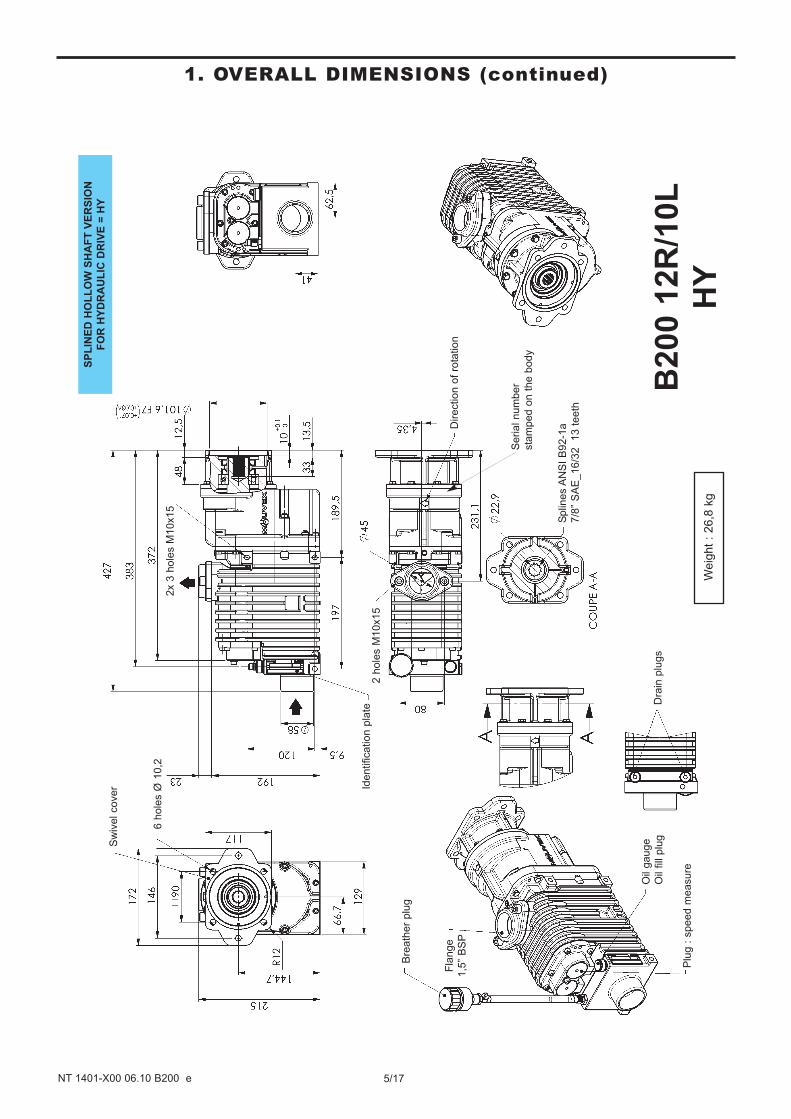
1. OVERALL DIMENSIONS (continued)
Identification p
late
6 h
ole
s Ø
10,2
Sw
ivel cover
Dra
in p
lugs
Bre
ath
er
plu
g
Plu
g :
speed m
easure
Oil
gauge
Oil
fill
plu
g
Fla
nge
1,5
” B
SP
2 h
ole
s M
10x15
2x 3
hole
s M
10x15
Direction o
f ro
tation
B200 1
2R
/10L
HY
Splin
es A
NS
I B
92-1
a
7/8
” S
AE
_16/3
2
13 t
eeth
Weig
ht
: 26,8
kg
SP
LIN
ED
HO
LL
OW
SH
AF
T V
ER
SIO
N
FO
R H
YD
RA
UL
IC D
RIV
E=
HY
Serial num
ber
sta
mped o
n t
he b
ody
6/17NT 1401-X00 06.10 B200 e
2. GENERAL DATA
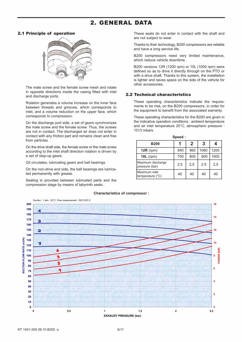
2.1 Principle of operation
The male screw and the female screw mesh and rotate
in opposite directions inside the casing fitted with inlet
and discharge ports.
Rotation generates a volume increase on the inner face
between threads and grooves, which corresponds to
inlet, and a volume reduction on the upper face, which
corresponds to compression.
On the discharge port side, a set of gears synchronizes
the male screw and the female screw. Thus, the screws
are not in contact. The discharged air does not enter in
contact with any friction part and remains clean and free
from particles.
On the drive shaft side, the female screw or the male screw
according to the inlet shaft direction rotation is driven by
a set of step-up gears.
Oil circulates, lubricating gears and ball bearings.
On the non-drive end side, the ball bearings are lubrica-
ted permanently with grease.
Sealing is provided between lubricated parts and the
compression stage by means of labyrinth seals.
These seals do not enter in contact with the shaft and
are not subject to wear.
Thanks to their technology, B200 compressors are reliable
and have a long service life.
B200 compressors need very limited maintenance,
which reduce vehicle downtime.
B200 versions 12R (1200 rpm) or 10L (1000 rpm) were
defined so as to drive it directly through on the PTO or
with a drive shaft. Thanks to this system, the installation
is lighter and saves space on the side of the vehicle for
other accessories.
2.2 Technical characteristicsThese operating characteristics indicate the require-
ments to be met, on the B200 compressors, in order for
the equipment to benefit from the associated warranty.
These operating characteristics for the B200 are given in
the indicative operation conditions : ambient temperature
and air inlet temperature 20°C, atmospheric pressure :
1013 mbars.
Speed :
B200 1 2 3 4
12R (rpm) 840 960 1080 1200
10L (rpm) 700 800 900 1000
Maximum discharge
pressure (bar)2,5 2,5 2,5 2,5
Maximum inlet
temperature (°C)40 40 40 40
0
10
20
30
40
50
60
70
80
90
100
110
120
130
140
150
160
170
180
190
200
0 0,5 1 1,5 2 2,5
EXHAUST PRESSURE (bar)
SU
CT
ION
FL
OW
RA
TE
(m
3/h
)
0
2
4
6
8
10
12
14
16
PO
WE
R (
kW
)
Suction : 1 atm , 20°C Flow measurement : ISO 5167-2
Characteristics of compressor :
2.3 Operating rangesThe operating ranges specified in the § TECHNICAL
CHARACTERISTICS give the conditions that must be
respected on mounting and packaging of the B200 com-
pressors, in order to be able to benefit from the guaran-
tees for these pieces of equipment.
MAXIMUM ACCEPTABLE DISCHARGE PRESSURE
(see § TECHNICAL CHARACTERISTICS)
The pressures correspond to the valve opening start
pressure. In a period of 60 seconds, it is acceptable to
have a pressure of 0,2 bar higher when the valve passes
the complete flow rate.
7/17NT 1401-X00 06.10 B200 e
2. GENERAL DATA (continued)
3. INSTALLATION
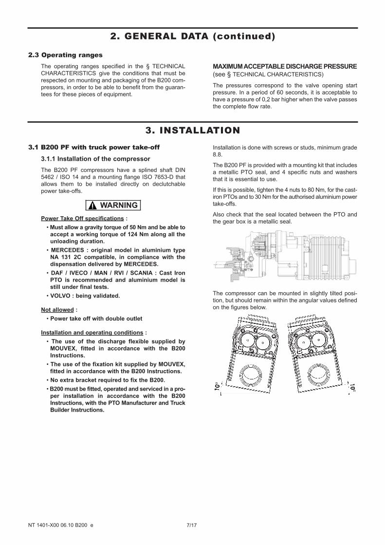
3.1 B200 PF with truck power take-off
3.1.1 Installation of the compressor
The B200 PF compressors have a splined shaft DIN
5462 / ISO 14 and a mounting flange ISO 7653-D that
allows them to be installed directly on declutchable
power take-offs.
Power Take Off specifications :
• Must allow a gravity torque of 50 Nm and be able to
accept a working torque of 124 Nm along all the
unloading duration.
• MERCEDES : original model in aluminium type
NA 131 2C compatible, in compliance with the
dispensation delivered by MERCEDES.
• DAF / IVECO / MAN / RVI / SCANIA : Cast Iron
PTO is recommended and aluminium model is
still under final tests.
• VOLVO : being validated.
Not allowed :
• Power take off with double outlet
Installation and operating conditions :
• The use of the discharge flexible supplied by
MOUVEX, fitted in accordance with the B200
Instructions.
• The use of the fixation kit supplied by MOUVEX,
fitted in accordance with the B200 Instructions.
• No extra bracket required to fix the B200.
• B200 must be fitted, operated and serviced in a pro-
per installation in accordance with the B200
Instructions, with the PTO Manufacturer and Truck
Builder Instructions.
Installation is done with screws or studs, minimum grade
8.8.
The B200 PF is provided with a mounting kit that includes
a metallic PTO seal, and 4 specific nuts and washers
that it is essential to use.
If this is possible, tighten the 4 nuts to 80 Nm, for the cast-
iron PTOs and to 30 Nm for the authorised aluminium power
take-offs.
Also check that the seal located between the PTO and
the gear box is a metallic seal.
The compressor can be mounted in slightly tilted posi-
tion, but should remain within the angular values defined
on the figures below.
WARNING
8/17NT 1401-X00 06.10 B200 e
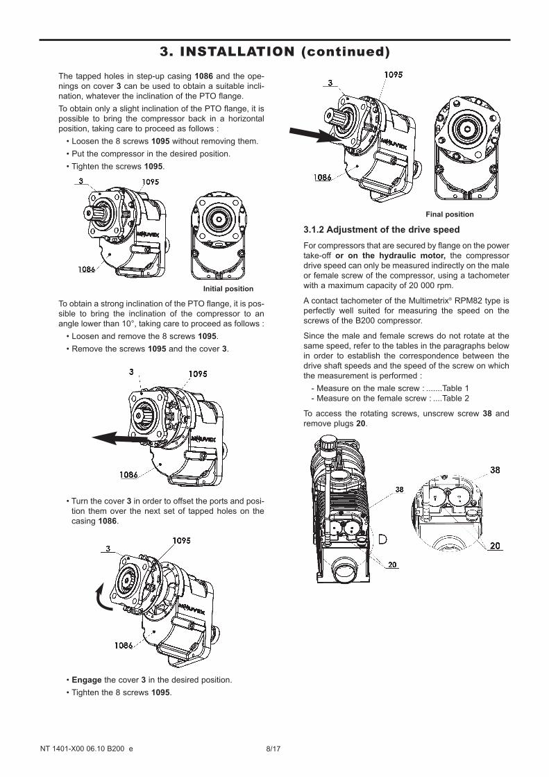
The tapped holes in step-up casing 1086 and the ope-
nings on cover 3 can be used to obtain a suitable incli-
nation, whatever the inclination of the PTO flange.
To obtain only a slight inclination of the PTO flange, it is
possible to bring the compressor back in a horizontal
position, taking care to proceed as follows :
• Loosen the 8 screws 1095 without removing them.
• Put the compressor in the desired position.
• Tighten the screws 1095.
Initial position
To obtain a strong inclination of the PTO flange, it is pos-
sible to bring the inclination of the compressor to an
angle lower than 10°, taking care to proceed as follows :
• Loosen and remove the 8 screws 1095.
• Remove the screws 1095 and the cover 3.
• Turn the cover 3 in order to offset the ports and posi-
tion them over the next set of tapped holes on the
casing 1086.
• Engage the cover 3 in the desired position.
• Tighten the 8 screws 1095.
Final position
3.1.2 Adjustment of the drive speed
For compressors that are secured by flange on the power
take-off or on the hydraulic motor, the compressor
drive speed can only be measured indirectly on the male
or female screw of the compressor, using a tachometer
with a maximum capacity of 20 000 rpm.
A contact tachometer of the Multimetrix® RPM82 type is
perfectly well suited for measuring the speed on the
screws of the B200 compressor.
Since the male and female screws do not rotate at the
same speed, refer to the tables in the paragraphs below
in order to establish the correspondence between the
drive shaft speeds and the speed of the screw on which
the measurement is performed :
- Measure on the male screw : .......Table 1
- Measure on the female screw : ....Table 2
To access the rotating screws, unscrew screw 38 and
remove plugs 20.
3. INSTALLATION (continued)
9/17NT 1401-X00 06.10 B200 e
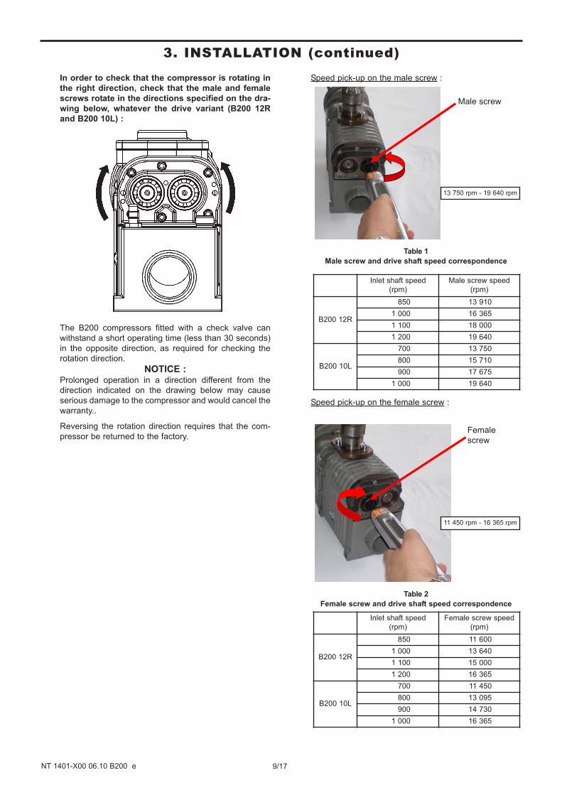
In order to check that the compressor is rotating in
the right direction, check that the male and female
screws rotate in the directions specified on the dra-
wing below, whatever the drive variant (B200 12R
and B200 10L) :
The B200 compressors fitted with a check valve can
withstand a short operating time (less than 30 seconds)
in the opposite direction, as required for checking the
rotation direction.
NOTICE :Prolonged operation in a direction different from the
direction indicated on the drawing below may cause
serious damage to the compressor and would cancel the
warranty..
Reversing the rotation direction requires that the com-
pressor be returned to the factory.
Speed pick-up on the male screw :
Table 1
Male screw and drive shaft speed correspondence
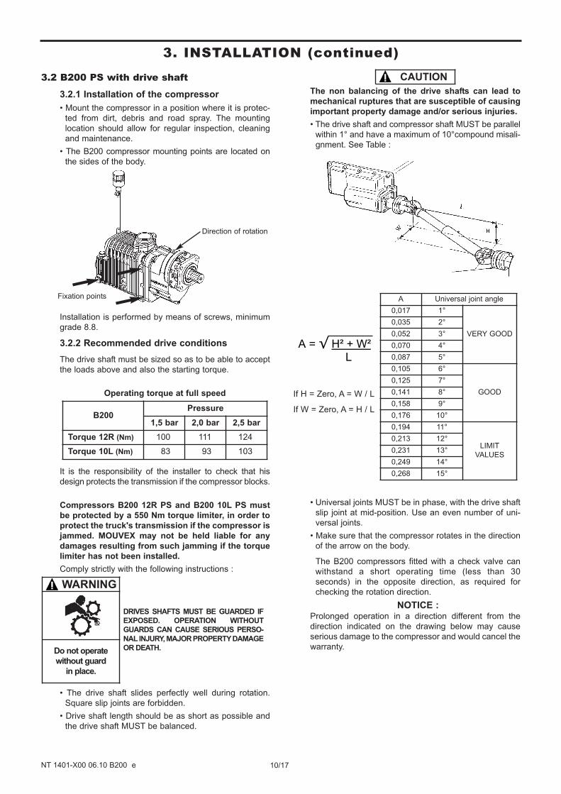
Speed pick-up on the female screw :
Table 2
Female screw and drive shaft speed correspondence
Inlet shaft speed
(rpm)
Female screw speed
(rpm)
B200 12R
850 11 600
1 000 13 640
1 100 15 000
1 200 16 365
B200 10L
700 11 450
800 13 095
900 14 730
1 000 16 365
Female
screw
11 450 rpm - 16 365 rpm
Inlet shaft speed
(rpm)
Male screw speed
(rpm)
B200 12R
850 13 910
1 000 16 365
1 100 18 000
1 200 19 640
B200 10L
700 13 750
800 15 710
900 17 675
1 000 19 640
Male screw
13 750 rpm - 19 640 rpm
3. INSTALLATION (continued)
10/17NT 1401-X00 06.10 B200 e
3.2 B200 PS with drive shaft
3.2.1 Installation of the compressor
• Mount the compressor in a position where it is protec-
ted from dirt, debris and road spray. The mounting
location should allow for regular inspection, cleaning
and maintenance.
• The B200 compressor mounting points are located on
the sides of the body.
Installation is performed by means of screws, minimum
grade 8.8.
3.2.2 Recommended drive conditions
The drive shaft must be sized so as to be able to accept
the loads above and also the starting torque.
Operating torque at full speed
It is the responsibility of the installer to check that his
design protects the transmission if the compressor blocks.
Compressors B200 12R PS and B200 10L PS must
be protected by a 550 Nm torque limiter, in order to
protect the truck's transmission if the compressor is
jammed. MOUVEX may not be held liable for any
damages resulting from such jamming if the torque
limiter has not been installed.
Comply strictly with the following instructions :
• The drive shaft slides perfectly well during rotation.
Square slip joints are forbidden.
• Drive shaft length should be as short as possible and
the drive shaft MUST be balanced.
The non balancing of the drive shafts can lead to
mechanical ruptures that are susceptible of causing
important property damage and/or serious injuries.
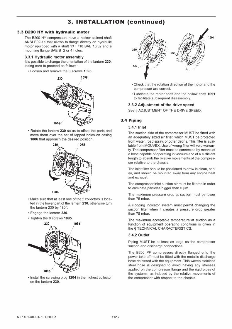
• The drive shaft and compressor shaft MUST be parallel
within 1° and have a maximum of 10°compound misali-
gnment. See Table :
• Universal joints MUST be in phase, with the drive shaft
slip joint at mid-position. Use an even number of uni-
versal joints.
• Make sure that the compressor rotates in the direction
of the arrow on the body.
The B200 compressors fitted with a check valve can
withstand a short operating time (less than 30
seconds) in the opposite direction, as required for
checking the rotation direction.
NOTICE :Prolonged operation in a direction different from the
direction indicated on the drawing below may cause
serious damage to the compressor and would cancel the
warranty.
If H = Zero, A = W / L
If W = Zero, A = H / L
A = H² + W² L
B200Pressure
1,5 bar 2,0 bar 2,5 bar
Torque 12R (Nm) 100 111 124
Torque 10L (Nm) 83 93 103
Direction of rotation
Fixation points
WARNING
Do not operate
without guard
in place.
DRIVES SHAFTS MUST BE GUARDED IF
EXPOSED. OPERATION WITHOUT
GUARDS CAN CAUSE SERIOUS PERSO-
NAL INJURY, MAJOR PROPERTY DAMAGE
OR DEATH.
A Universal joint angle
0,017 1°
VERY GOOD
0,035 2°
0,052 3°
0,070 4°
0,087 5°
0,105 6°
GOOD
0,125 7°
0,141 8°
0,158 9°
0,176 10°
0,194 11°
LIMIT
VALUES
0,213 12°
0,231 13°
0,249 14°
0,268 15°
CAUTION
3. INSTALLATION (continued)
11/17NT 1401-X00 06.10 B200 e
3.3 B200 HY with hydraulic motorThe B200 HY compressors have a hollow splined shaft
ANSI B92-1a that allows to flange directly on hydraulic
motor epuipped with a shaft 13T 718 SAE 16/32 and a
mounting flange SAE B 2 or 4 holes.
3.3.1 Hydraulic motor assemblyIt is possible to change the orientation of the lantern 230,
taking care to proceed as follows :
• Loosen and remove the 8 screws 1095.
• Rotate the lantern 230 so as to offset the ports and
move them over the set of tapped holes on casing
1086 that approach the desired position.
• Make sure that at least one of the 2 collectors is loca-
ted in the lower part of the lantern 230, otherwise turn
the lantern 230 by 180°.
• Engage the lantern 230.
• Tighten the 8 screws 1095.
• Install the screwing plug 1204 in the highest collector
on the lantern 230.
• Check that the rotation direction of the motor and the
compressor are correct.
• Lubricate the motor shaft and the hollow shaft 1091
to facilitate subsequent disassembly.
3.3.2 Adjustment of the drive speed
See § ADJUSTMENT OF THE DRIVE SPEED.
3.4 Piping
3.4.1 Inlet
The suction side of the compressor MUST be fitted with
an adequately sized air filter, which MUST be protected
from water, road spray, or other debris. This filter is avai-
lable from MOUVEX. Use of wrong filter will void warran-
ty. The compressor filter must be connected by means of
a hose capable of operating in vacuum and of a sufficient
length to absorb the relative movements of the compres-
sor relative to the chassis.
The inlet filter should be positioned to draw in clean, cool
air, and should be mounted away from any engine heat
and exhaust.
The compressor inlet suction air must be filtered in order
to eliminate particles bigger than 5 µm.
The maximum pressure drop at suction must be lower
than 75 mbar.
A clogging indicator system must permit changing the
suction filter when it creates a pressure drop greater
than 75 mbar.
The maximum acceptable temperature at suction as a
function of equipment operating conditions is given in
the § TECHNICAL CHARACTERISTICS.
3.4.2 Outlet
Piping MUST be at least as large as the compressor
suction and discharge connections.
The B200 PF compressors directly flanged onto the
power take-off must be fitted with the metallic discharge
hose delivered with the equipment. This woven stainless
steel hose is designed to avoid having any stresses
applied on the compressor flange and the rigid pipes of
the systems, as induced by the relative movements of
the compressor with respect to the chassis.
3. INSTALLATION (continued)
For the B200 PF, it should cancel the stresses on the
flange, as induced by the movement of the compressor,
and respect the rules below :
• install a 90° elbow between the flange and the hose.
• support the stainless steel hose correctly at its end part.
• the hose output pins should be mounted in the same
horizontal plane. Make sure that the installation
allows a compressor displacement of ± 5 cm to be
obtained.
• on the same horizontal plane, if the output pins are
not parallel, the bending radius must be as large as
possible, and in any case at least equal to 50 cm.
Make sure that the installation allows a compressor
displacement of ± 5 cm to be obtained.
Top view
During installation, position a pressure gage on the com-
pressor output, so as to measure the operating pressu-
re. The measurement should be done at the discharge
flange level and should not exceed 2,5 bar over the allo-
wable operating range of the compressor.
The compressor must be protected by a check relief/
safety valve. The check valve prevents any air from
returning in the compressor when it is no longer in oper-
ation. The safety valve protects the compressor against
possible overpressure. The maximum set point of the
valve is 2,5 bar. If there is a drop in pressure between
the pressure relief valve and the compressor, reduce
the pressure relief valve setting by the value of the pres-
sure drop. It is the installor responsability to check that
the relief valve is compliant with the compressor per-
formance for the application speed. The check and relief
valve is available from MOUVEX. This check and relief
valve MUST NOT be mounted in a way that broken
pieces could fall into the compressor.
Ensure that ALL components are capable of operation at
the maximum system pressure limits and that all vessels
are adequately protected by SEPARATE relief valves.
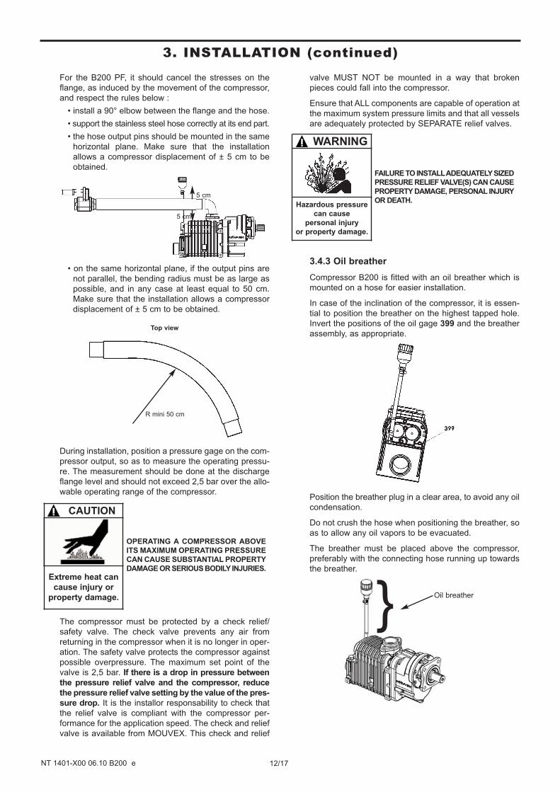
3.4.3 Oil breather
Compressor B200 is fitted with an oil breather which is
mounted on a hose for easier installation.
In case of the inclination of the compressor, it is essen-
tial to position the breather on the highest tapped hole.
Invert the positions of the oil gage 399 and the breather
assembly, as appropriate.
Position the breather plug in a clear area, to avoid any oil
condensation.
Do not crush the hose when positioning the breather, so
as to allow any oil vapors to be evacuated.
The breather must be placed above the compressor,
preferably with the connecting hose running up towards
the breather.
Oil breather}
R mini 50 cm
5 cm
5 cm
FAILURE TO INSTALL ADEQUATELY SIZED
PRESSURE RELIEF VALVE(S) CAN CAUSE
PROPERTY DAMAGE, PERSONAL INJURY
OR DEATH.
WARNING
Hazardous pressure
can cause
personal injury
or property damage.
CAUTION
Extreme heat can
cause injury or
property damage.
OPERATING A COMPRESSOR ABOVE
ITS MAXIMUM OPERATING PRESSURE
CAN CAUSE SUBSTANTIAL PROPERTY
DAMAGE OR SERIOUS BODILY INJURIES.
12/17NT 1401-X00 06.10 B200 e
3. INSTALLATION (continued)
13/17NT 1401-X00 06.10 B200 e
4. USE OF COMPRESSOR
4.1 Lubricant recommendationsThe MOUVEX screw compressor operates with MOUVEX
BSC oil.
With BSC oil, oil change is recommended every year or
300 working hours.
In case of operations done under minus 10°C, BSC oil
viscosity sharply increases and can generate starting
troubles.
In order to avoid these troubles, we suggest 2 alternatives :
• To warm up the compressor’s housing before starting.
• To replace temporarily our BSC oil by standard oil
SAE 10W40.
SAE 10W40 oil draining frequency must not exceed 100 h
and must be limited to a seasonal using.
BSC oil will have to be moved back as soon as the
temperature average level goes back up to minus
10°C, otherwise our warranty is void.
4.2 Filling of lubricant
Our compressors are delivered without oil. The use
of a compressor with an oil level different from 1,2 l
± 10% can lead to important property damage and
serious injuries.
Before starting the system, fill the casing with oil so that
the oil level is set between the min and max value of the
gauge.
4.3 Operation• The compressor must be started with the discharge
valves open.
• Check the compressor drive shaft rotation direction :
- B200 12R PS and B200 10L PS : The drive shaft
rotation direction must match with the arrow on the
body of the compressor.
- B200 12R PF and B200 10L PF : Refer to § DIRECT
INSTALLATION TRUCK POWER TAKE-OFF.
NOTICE :Prolonged operation in a direction other than the
direction of the arrow on the body can cause serious
damages to the compressor and would cancel the
warranty.
• The compressor shall be stopped without any counter-
pressure at discharge.
• At commissioning, check that the combinations of
rotation speed and discharge pressure of the com-
pressors are in conformity with those indicated in §
TECHNICAL CHARACTERISTICS.
During operation, the temperature of the surface of
a compressor and nearby parts can be in the region
of 200°C. The compressor and the parts located
nearby are thus susceptible of provoking serious
burns and property damage. Be careful to not
approach elements that are sensitive to heat and
affix plates informing users that the compressor is
hot, to prevent any risk of burns.
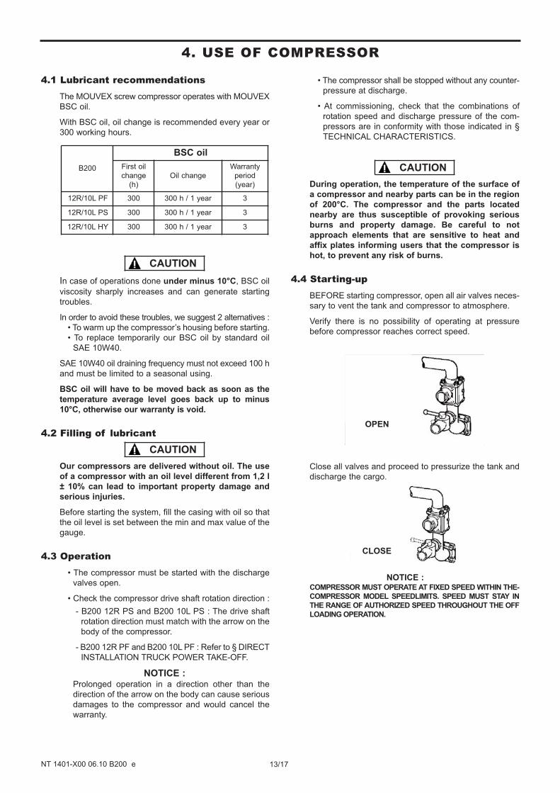
4.4 Starting-upBEFORE starting compressor, open all air valves neces-
sary to vent the tank and compressor to atmosphere.
Verify there is no possibility of operating at pressure
before compressor reaches correct speed.
Close all valves and proceed to pressurize the tank and
discharge the cargo.
NOTICE :COMPRESSOR MUST OPERATE AT FIXED SPEED WITHIN THE-
COMPRESSOR MODEL SPEEDLIMITS. SPEED MUST STAY IN
THE RANGE OF AUTHORIZED SPEED THROUGHOUT THE OFF
LOADING OPERATION.
CLOSE
OPEN
B200
BSC oil
First oil
change
(h)
Oil change
Warranty
period
(year)
12R/10L PF 300 300 h / 1 year 3
12R/10L PS 300 300 h / 1 year 3
12R/10L HY 300 300 h / 1 year 3
CAUTION
CAUTION
CAUTION
14/17NT 1401-X00 06.10 B200 e
5. MAINTENANCE
5.1 Maintenance schedules
After every cleaning of the truck
Always run the compressor for 15 minutes to remove
any water that inadvertently gets into the piping. DO
NOT fog or introduce anti-corrosive liquids into the com-
pressor to prevent corrosion : Use of liquids in the com-
pressor will cause failure.
Weekly
1. The compressor should be run for at least 15 minutes
to prevent moisture from collecting inside. This will
reduce the risk of corrosion damage to the compres-
sor and other equipment in the piping.
2. Inspect and clean air filter. Inspect DAILY if operating
in dirty or severe environment. Check the condition of
the inlet filter hose for splits and tears. Replace or
repair as necessary.
3. Inspect compressor, system piping and components.
Clean or repair as necessary.
4. Check power transmission line (pulley, shaft, torque
limitor...).
5. Check the air filter clogging indicator. When the indicator
turns red, replace the filter cartridge. Before replacing
the cartridge with a new one, clean the inside of the fil-
ter's body with a clean damp cloth.
Per manufacturer’ s recommendations
Lubricate the universal seal (for B200 PS models).
Monthly
1. Check the relief valve(s) for wear and proper settings.
Replace or adjust as necessary.
2. Check that the check valve works properly, replace as
necessary.
3. Check the oil level and complete if necessary.
Yearly :
1. Check tightness of the 4 mounting nuts on the B200 PTO.
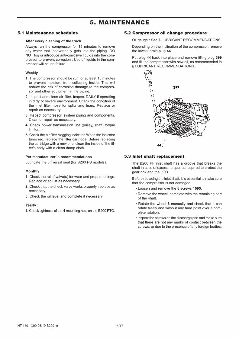
5.2 Compressor oil change procedureOil gauge : See § LUBRICANT RECOMMENDATIONS.
Depending on the inclination of the compressor, remove
the lowest drain plug 44.
Put plug 44 back into place and remove filling plug 399
and fill the compressor with new oil, as recommended in
§ LUBRICANT RECOMMENDATIONS.
5.3 Inlet shaft replacementThe B200 PF inlet shaft has a groove that breaks the
shaft in case of excess torque, as required to protect the
gear box and the PTO.
Before replacing the inlet shaft, it is essential to make sure
that the compressor is not damaged :
• Loosen and remove the 8 screws 1095.
• Remove the wheel, complete with the remaining part
of the shaft.
• Rotate the wheel 6 manually and check that it can
rotate freely and without any hard point over a com-
plete rotation.
• Inspect the screws on the discharge part and make sure
that there are not any marks of contact between the
screws, or due to the presence of any foreign bodies.
15/17NT 1401-X00 06.10 B200 e
5.1 CompressorThe equipment must be systematically stored in an area shel-
tered from bad weather.
The equipment must bear its original protective components
until it is installed in its final application.
If installation is interrupted, put back in place the original pro-
tective components or equivalent components.
5.2 BSC oilIn its unopened original container in a dry, frost-free and
light-free place.
The maximum shelf life is approx. 60 months.
6. STORAGE CONDITIONS
The compressor must be scrapped in compliance with the
regulations in force.
During this operation, particular care must be paid to the drai-
nage stages of the compressor.
7. SCRAPPING
5. MAINTENANCE (continued)
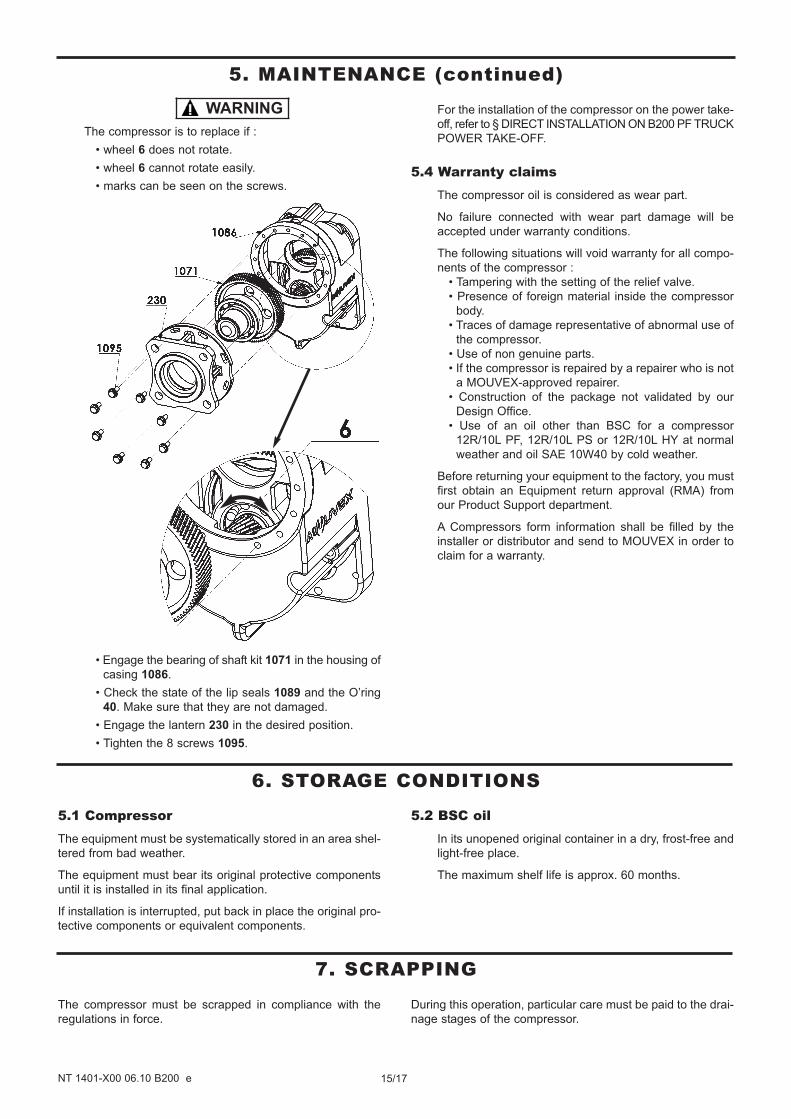
The compressor is to replace if :
• wheel 6 does not rotate.
• wheel 6 cannot rotate easily.
• marks can be seen on the screws.
• Engage the bearing of shaft kit 1071 in the housing of
casing 1086.
• Check the state of the lip seals 1089 and the O’ring
40. Make sure that they are not damaged.
• Engage the lantern 230 in the desired position.
• Tighten the 8 screws 1095.
For the installation of the compressor on the power take-
off, refer to § DIRECT INSTALLATION ON B200 PF TRUCK
POWER TAKE-OFF.
5.4 Warranty claimsThe compressor oil is considered as wear part.
No failure connected with wear part damage will be
accepted under warranty conditions.
The following situations will void warranty for all compo-
nents of the compressor :
• Tampering with the setting of the relief valve.
• Presence of foreign material inside the compressor
body.
• Traces of damage representative of abnormal use of
the compressor.
• Use of non genuine parts.
• If the compressor is repaired by a repairer who is not
a MOUVEX-approved repairer.
• Construction of the package not validated by our
Design Office.
• Use of an oil other than BSC for a compressor
12R/10L PF, 12R/10L PS or 12R/10L HY at normal
weather and oil SAE 10W40 by cold weather.
Before returning your equipment to the factory, you must
first obtain an Equipment return approval (RMA) from
our Product Support department.
A Compressors form information shall be filled by the
installer or distributor and send to MOUVEX in order to
claim for a warranty.
WARNING

16/17NT 1401-X00 06.10 B200 e
8. COMPRESSORS FORM INFORMATION
MOUVEX After Sales Service Tel : (33) 3 86 49 86 03 Date :Z.I. La Plaine des Isles Fax : (33) 3 86 49 86 48 Followed by :89000 AUXERRE - France File :
A – Name and address of user
Person to contact : Phone Nr :B – Name and address of installator
Person to contact : Phone Nr :
C - Material's serial number D - Starting up date
Running time estimation
PTO flanged Propshaft drive system (direct PTO drive) Compressor's speed30R 20R 19R 13R 22L 15L Operating pressure12R 10L Torque limiter Pressure relief valve setting (value) Belt drive system PTO ratio : Package air cooler Package RTI Product transfered
Air connection on truck chimney Direct air connectionFlexible pipe between filter and compressorInox pipe between filter and compressor
Blocking Leakage Noise, vibration Other
I - Has the machine been replaced by a new one ? If yes which is the serial numberJ - Has the machine been replaced by a renoved one ? If yes which is the serial number
the time of the incident
Please send us back this completed form by fax or E mail as quick as possible.
Other (electric, thermic or hydraulic motor)
G - Suction conditions
H - DESCRIPTION OF THE FAILURE
K - Remarks and comments of the user about the problem :
In order to properly deal with the return material, please fill in this form.
E - Installation details F - Operating parameters
Motor speed (tachometer) at
COMPRESSORS
FORM INFORMATION
FORM
RMA / YY / NNN
SAV-002-02.2010
Before any material return, it is required to get an authorization from MOUVEX.
17/17NT 1401-X00 06.10 B200 e
CUM 220103 FORM-QUA-18-4
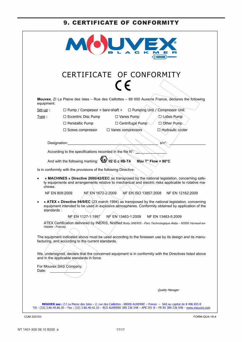
CERTIFICATE OF CONFORMITY
Mouvex, ZI La Plaine des Isles – Rue des Caillottes – 89 000 Auxerre France, declares the following equipment:
Set-up : Pump / Compessor « bare-shaft » Pumping Unit / Compressor Unit
Type : Eccentric Disc Pump Vanes Pump Lobes Pump
Peristaltic Pump Centrifugal Pump Other Pump
Scews compressor Vanes compressors Hydraulic cooler
Designation: s/n°:
According to the specifications recorded in the file N°: _
And with the following marking: II2 G c IIB-T4 Max T° Flow = 80°C Is in conformity with the provisions of the following Directive:
« MACHINES » Directive 2006/42/EEC as transposed by the national legislation, concerning safe-ty equipments and arrangements relative to mechanical and electric risks applicable to rotative ma-chines.
NF EN 809:2009 NF EN 1672-2:2009 NF EN ISO 13857:2008 NF EN 12162:2009
« ATEX » Directive 94/9/EC (23 march 1994) as transposed by the national legislation, concerning equipment intended to be used in explosive atmospheres. Conformity obtained by application of the standards :
NF EN 1127-1:1997 NF EN 13463-1:2009 NF EN 13463-5:2009
ATEX Certification delivered by INERIS, Notified Body (INERIS - Parc Technologique Alata – 60550 Verneuil-en-Halatte - France).
The equipment indicated above must be used according to the foreseen use by its design and its manu-facturing, and according to the current standards. We, undersigned, declare that the concerned equipment is in conformity with the Directives listed above and in the applicable standards in force. For Mouvex SAS Company. Date: _______________
Quality Manager
MOUVEX sas : Z.I La Plaine des Isles – 2, rue des Caillottes - 89000 AUXERRE – France – SAS au capital de 8 496 855 € Tél : (33) 3.86.49.86.30 – Fax : (33) 3.86.46.42.10 – RCS AUXERRE 389 236 548 – APE 291 B – FR 85 389 236 548 – www.mouvex.com
9. CERTIFICATE OF CONFORMITY