b2311 en 0513 - contrive.mobi
TRANSCRIPT
CONTRIVE S.R.L.Via Enrico Fermi 18 I-24040 SUISIO (Bergamo)Tel. +39 (0)35 4948236 Fax +39 (0)35 4933759
B2311.EN / 0513 www.contrive.itTHIS DEVICE SHOULD BE INSTALLED ONLY BY QUALIFIED PERSONNEL
AL2-MBU
Carefully read the instruction manual in its entirety and keep it safe for futurereference. It is essential to know the information and comply with the instructionsgiven in the manual to ensure the is installed, used and serviced correctlyand safely.
ALWAYS FOLLOW SAFETY PROCEDURES.
IF THE DEVICE HAS BEEN STORED IN A COLD ENVIRONMENT, THENCONDENSATION CAN OCCUR. BEFORE STARTING OPERATIONS, THEDEVICE MUST BE ABSOLUTELY DRY. THUS, AN ACCLIMATIZATION PERIODOFAT LEASTTHREE HOURS MUST BE OBSERVED.
In order to prevent danger to life or property, it is the responsibility of the systemdesigner to incorporate redundant protective mechanism appropriate to the riskinvolved.
DO NOT ATTEMPT TO INSTALL, REPLACE OR PERFORM MAINTENANCE ONWHILE IT IS ENERGIZED, BEFORE REMOVING OR MOUNTING A
MODULE, DISCONNECT BOTH THE POWER TO THE CONTROLLER AND THEFIELDBUS.MAKE SURE THE ENTIRE CONTROLLER IS REASSEMBLED BEFORESWITCHING THE POWER BACK ON. DEATH OR SEVERE PERSONAL INJURYCAN RESULT FROM CONTACT WITH ENERGIZED EQUIPMENT.ALWAYS VERIFYTHAT NO VOLTAGE IS PRESENT BEFORE PROCEEDING.
This unit is not authorised for use as critical component in life-support devices orsystems unless a specific written agreement has been given.
No complex software or hardware system is perfect.Bugs are always present in a system of any size.
All units are 100% functionally tested. Specifications are based on characterisationof tested sample units rather than testing over temperature and voltage each unit.
Contrive disclaims all liability for damage to the fitting or to other property or personsderiving from installation, use and maintenance that have not been carried out inconformity with this instruction manual, which must always accompany the fitting.
AL2-MBU
The Modbus Gateway module is an optional device for Mitsubishicontrollers which enables the connection to a Modbus system.
The controller is considered as a slave on the Modbus network.
Through the Modbus Gateway module it is possible to:• Read (and write) digital inputs• Read analog inputs• Read and write digital outputs• Read and write analog outputs• Read and write Communication Bits• Read and write Communication Words• Read system bits
AL2-MBU
AL2-MBU
�
�
�
�
2
2
Before attempting to use , the following original MITSUBISHI manualsshould be carefully read and understood:
For any information on 2 controller and its derivate products, please refer to theliterature provided by MITSUBISHI and available for download at:
These manuals will guide the reader in the correct programming and operation of the
2 controllers.
AL2-MBU
• Hardware Manual• Programming Manual• Software Manual• Communication Manual
www.mitsubishi-automation.com
SAFETY INFORMATION
PRODUCT DESCRIPTION
2311.00.00 AL2-MBU MODBUS GATEWAY FOR AL2
Modbus® is a registered trademark of Schneider Electric.
CONTRIVE RESERVES THE RIGHT TO MODIFY THE CHARACTERISTICS STATEDIN THIS INSTRUCTION MANUAL AT ANY TIME AND WITHOUT PRIOR NOTICE.
© COPYRIGHT 2002...2007 CONTRIVE SRL ITALY. ALL RIGHTS RESERVED.
AL2-MBU Advanced Manual is available for download at: www.contrive.it
USER GUIDE
AL2-MBU MODBUS COMMUNICATION MODULEFOR MITSUBISHI ALPHA CONTROLLERS
FITTING BUS INTERFACE
DECLARATION OF CONFORMITY
Company identification:
Product identification:
The manufacturer declare the conformity of the equipment with the provisionsof the following EC Directive(s) when installed in accordance with theinstallation instructions :
Conformance via a Technical Construction File is declared using all parts ofthe following standards (EMC only) :
Manufacturer: Contrive, SrlVia Enrico Fermi 18 24040 Suisio Italy
Brand: ContriveEquipment name: AL2-MBUEquipment type: Modbus Gateway
Suisio, Italy July 26, 2007
89/336/EEC EMC Directive as amended by 93/68/EEC
EN 50081-1 (1995)Electromagnetic compatibility. Generic emission standard.Part 1 : Residential, commercial and light industry.
�
� 73/23/EEC LVD Directive as amended by 93/68/EEC
EN 50082-2 (1995)Electromagnetic compatibility. Generic immunity standard.Part 2 : Industrial environment.
�
�
To install ake surethat there is no voltage applied
to controller.
.
Carefully remove the factory
fitted expansion port coveror special module cover.
Make all the connections andsettings before to install the
into the cavity.
Install the into thecavity, carefully placing theconnec to r to match thecounterpart in the base and thecable in the channel locatedon the top side.
Once Modbus Gateway has been installed the connectionfor the cable is no longer available.
Controller must be configured for
AL2-MBU
AL2-MBU
AL2-MBU [1]
[2]
WARNING
AL2-MBUAL2-GSM-CAB
StationAddress = 0
m
2
Release screw and keep
2
Replace the 2 cover takingcare that there is nointerference withand all connector andcables are in the correctposition.
\Tighten screw to a torque of 0.4 N/m.
2
�
�
�
�
[A]
AL2-MBU
[A]
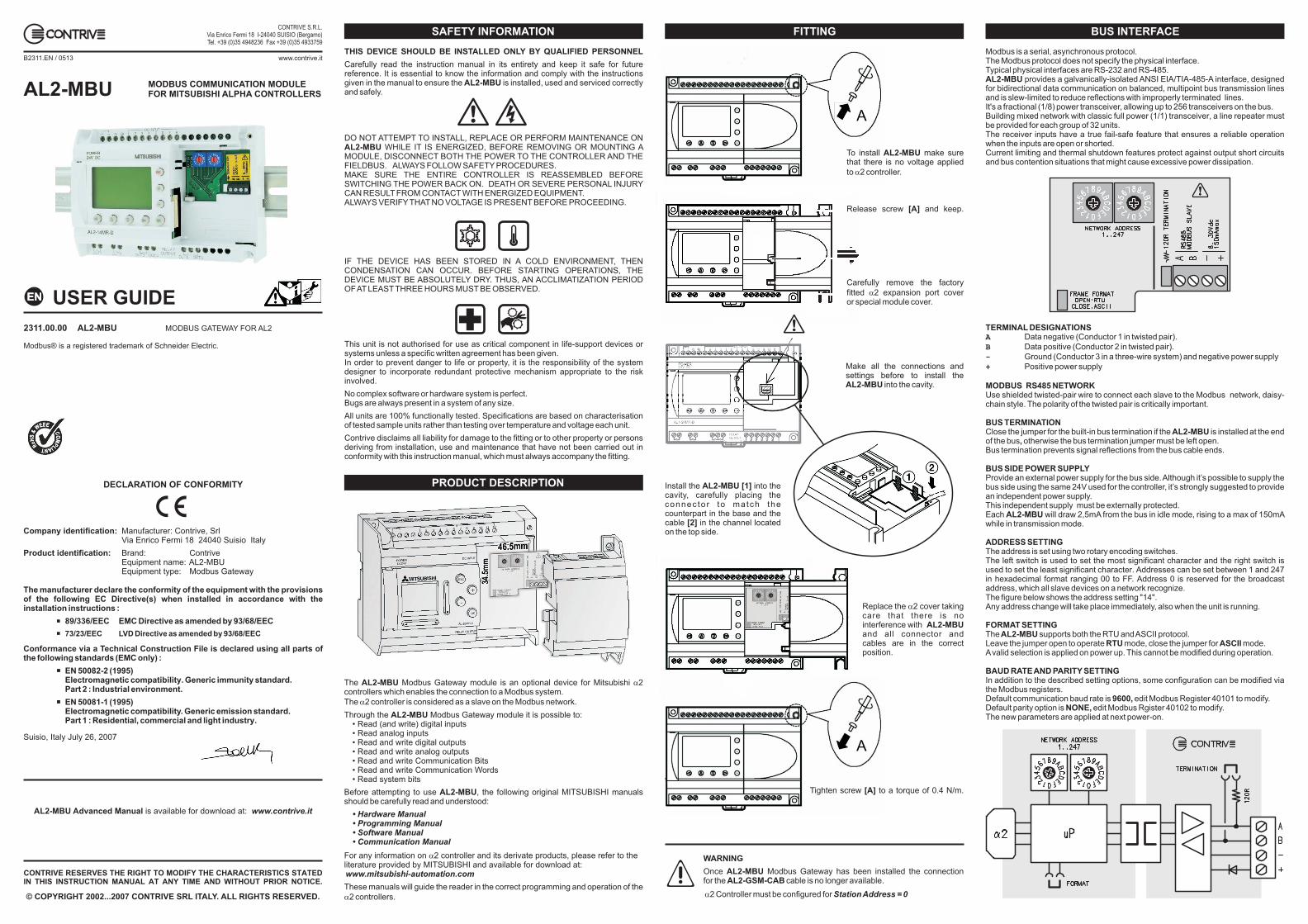
Modbus is a serial, asynchronous protocol.The Modbus protocol does not specify the physical interface.Typical physical interfaces are RS-232 and RS-485.
provides a galvanically-isolated ANSI EIA/TIA-485-A interface, designedfor bidirectional data communication on balanced, multipoint bus transmission linesand is slew-limited to reduce reflections with improperly terminated lines.It's a fractional (1/8) power transceiver, allowing up to 256 transceivers on the bus.Building mixed network with classic full power (1/1) transceiver, a line repeater mustbe provided for each group of 32 units.The receiver inputs have a true fail-safe feature that ensures a reliable operationwhen the inputs are open or shorted.Current limiting and thermal shutdown features protect against output short circuitsand bus contention situations that might cause excessive power dissipation.
Data negative (Conductor 1 in twisted pair).
Data positive (Conductor 2 in twisted pair).
Ground (Conductor 3 in a three-wire system) and negative power supply
Positive power supply
Use shielded twisted-pair wire to connect each slave to the Modbus network, daisy-chain style. The polarity of the twisted pair is critically important.
Close the jumper for the built-in bus termination if the is installed at the endof the bus otherwise the bus termination jumper must be left open.Bus termination prevents signal reflections from the bus cable ends.
Provide an external power supply for the bus side.Although it’s possible to supply thebus side using the same 24V used for the controller, it’s strongly suggested to providean independent power supply.This independent supply must be externally protected.Each will draw 2,5mA from the bus in idle mode, rising to a max of 150mAwhile in transmission mode.
The address is set using two rotary encoding switches.The left switch is used to set the most significant character and the right switch isused to set the least significant character. Addresses can be set between 1 and 247in hexadecimal format ranging 00 to FF. Address 0 is reserved for the broadcastaddress, which all slave devices on a network recognize.The figure below shows the address setting "14".Any address change will take place immediately, also when the unit is running.
The supports both the RTU andASCII protocol.Leave the jumper open to operate mode, close the jumper for mode.Avalid selection is applied on power up. This cannot be modified during operation.
In addition to the described setting options, some configuration can be modified viathe Modbus registers.Default communication baud rate is edit Modbus Register 40101 to modify.Default parity option is edit Modbus Rgister 40102 to modify.The new parameters are applied at next power-on.
AL2-MBU
TERMINAL DESIGNATIONS
MODBUS RS485 NETWORK
BUS TERMINATIONAL2-MBU
,
BUS SIDE POWER SUPPLY
AL2-MBU
ADDRESS SETTING
FORMAT SETTINGAL2-MBU
RTU ASCII
BAUD RATEAND PARITY SETTING
9600,NONE,
A
B
-
+
The following table highlights the subset of standard Modbus supported functions(the reference register addresses that the function operates on are also indicated):
responds to the master within the defined(nothing will be issued after this timeout), it uses the function code field to indicate anormal (error-free) response. A valid answer is given if at least one of read coil orregister is valid.An error is given when the whole addresses are not valid.
[1] Maximum number of registers/coils in a single request is limited to 64.
AL2-MBU AlphaXL COM TIMEOUT
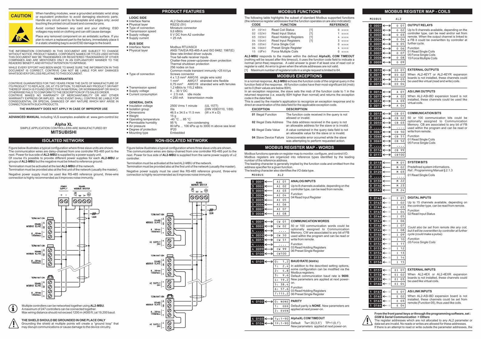
Modbus functions operate on register map to monitor, configure, and control I/O.Modbus registers are organized into reference types identified by the leadingnumber of the reference address.The leading character is generally implied by the function code and omitted from theaddress specifier for a given function.The leading character also identifies the I/O data type.
ANALOG INPUTS
Up to 8 channels available, depending on thecontroller type, can be read from remote.
Function04 Read Input Register
BAUD RATE (kbit/s)
Function03 Read Holding Registers06 Preset Single Register
In addition to the described setting options,some configuration can be modified via theModbus registers.Default communication baud rate is .New parameters are applied at next power-on.
9600
COMMUNICATION WORDS
50 or 100 communication words could beoptionally assigned to CommunicationMemory. CW are associated to any bit of FBused within the program and can be read orwrite from remote.
Function03 Read Holding Registers06 Preset Single Register
ISOLATED NETWORK
MODBUS REGISTER MAP - COILS
NON-ISOLATED NETWORK
MODBUS REGISTER MAP - WORDS
MODBUS FUNCTIONS
MODBUS EXCEPTIONS
Figure below illustrates a typical configuration where three slave units are shown.The communication wires are daisy-chained from one controller RS-485 port to thenext. Power for bus side of is supplied by a power supply unit.Of course it’s possible to provide different power supplies for each orgroups of but the negative must be linked to reference ground.
Termination must be activated at the last of the network.Termination must be provided also at the first unit of the network (usually the master).
Negative power supply must be used like RS-485 reference ground, three-wireconnection is highly recommended as it improves noise immunity.
AL2-MBUAL2-MBU
AL2-MBU
AL2-MBU
Figure below illustrates a typical configuration where three slave units are shown.The communication wires are daisy-chained from one controller RS-485 port to the
next. Power for bus side of is supplied from the same power supply of 2controller.
Termination must be activated at the lastAL2-MBU of the network.Termination must be provided also at the first unit of the network (usually the master).
Negative power supply must be used like RS-485 reference ground, three-wireconnection is highly recommended as it improves noise immunity.
AL2-MBU �
Multiple controllers can be networked together using .Amaximum of 247 controllers can be connected together.Max wiring distance should not exceed 1200 m (4000 ft.) at 19,200 baud.
AL2-MBU
THE SHIELD SHOULD BE GROUNDED IN ONE PLACE ONLYGrounding the shield at multiple points will create a “ground loop” thatmay disrupt communications or cause damage to the device circuitry.
When handling modules, wear a grounded antistatic wrist strapor equivalent protection to avoid damaging electronic parts.Handle any circuit card by its faceplate and edges only; avoidtouching the printed circuit board and connector pins.
Avoid contact between any card and your clothing: ESDvoltages may exist on clothing and can still cause damage.
Place any removed component on an antistatic surface. If youplan to return a replaced part to the factory, immediately place itin a static shielding bag to avoid ESD damage to the board.
The register addresses which are not allocated to any AL2 parameter ordata set are invalid. No reads or writes are allowed for these addresses.If there is an attempt to read or write outside the parameter addresses, the
From the front panel keys or through the programming software, set :>GSM & Serial Communication Others
ADVANCED MANUAL including VLS examples available at: www.gsm-control.biz
Alpha XLSIMPLE APPLICATION CONTROLLERS ARE MANUFACTURED BY
MITSUBISHI
0 00010 0001
3 00013 0001
0 00020 0002
3 00023 0002
0 00030 0003
3 00033 0003
0 00040 0004
3 00043 0004
0 00050 0005
3 00053 0005
0 00060 0006
3 00063 0006
0 00070 0007
3 00073 0007
0 00080 0008
3 00083 0008
0 00090 0009
0 00100 0010
4 00014 0001
0 00110 0011
4 00024 0002
0 00120 0012
0 00130 0013
4 ....4 ....
4 00504 0050
4 00514 0051
4 ....4 ....
4 00994 0099
4 01004 0100
4 01014 0101
4 01024 0102
0 00140 0014
0 00150 0015
0 00160 0016
0 00170 0017
0 00180 0018
0 00190 0019
0 00500 0050
0 ....0 ....
0 00670 0067
0 00680 0068
0 00690 0069
0 ....0 ....
0 01160 0116
0 01170 0117
0 01180 0118
0 01190 0119
0 01200 0120
0 ....0 ....
0 01390 0139
0 01400 0140
0 01410 0141
1 01421 0142
1 01431 0143
1 01441 0144
1 01451 0145
1 01461 0146
1 01471 0147
1 01481 0148
1 01491 0149
1 01501 0150
1 01511 0151
1 01521 0152
1 01531 0153
1 01541 0154
1 01551 0155
1 01561 0156
1 01571 0157
1 01581 0158
1 01591 0159
1 01601 0160
1 01611 0161
1 01621 0162
1 01631 0163
1 01641 0164
O 01
AI 01
O 02
AI 02
O 03
AI 03
O 04
AI 04
O 05
AI 05
O 06
AI 06
O 07
AI 07
O 08
AI 08
O 09
EO 01
CW 01
EO 02
CW 02
EO 03
EO 04
....
CW 50
CW 51
....
CW 99
CW100
0: 1.2
0: NONE
1: 2.4
1: ODD
2: 4.8
2: EVEN
3: 9.6
4: 19.2
5: 38.4
6: 57.6
7:115.2
A 01
A 02
A 03
A 04
CB 01
CB 02
CB 03
....
CB 50
CB 51
CB 52
....
CB 99
CB100
M 01
M 02
M 03
....
M 22
M 23
M 24
I 01
I 02
I 03
I 04
I 05
I 06
I 07
I 08
I 09
I 10
I 11
I 12
I 13
I 14
I 15
EI 01
EI 02
EI 03
EI 04
E 01
E 02
E 03
E 04
MODBUS
MODBUS
AL2
AL2
OUTPUT RELAYS
Up to 9 channels available, depending on thecontroller type, can be read and/or set fromremote. When the output channel is linked toa FB it could be overwritten by controller atfurther cycle.
Function01 Read Single Coils05 Force Single Coils15 Force Multiple Coils
EXTERNAL OUTPUTS
When AL2-4EYT or AL2-4EYR expansionboards is not installed, these channels couldbe used like virtual (read and write) coils.
PARITY
Default parity is . New parameters areapplied at next power-on.
NONE
In a normal response, echoes the function code of the original query in thefunction field of the response. All function codes have their most-significant bit (msb)set to 0 (their values are below 80H).In an exception response, the slave sets the msb of the function code to 1 in thereturned response (i.e. exactly 80H higher than normal) and returns the exceptioncode in the data field.This is used by the master's application to recognize an exception response and todirect an examination of the data field for the applicable exception code.
AL2-MBU
EXCEPTION DESCRIPTION
01
02
03
04
Illegal Function The function code received in the query is notallowed or invalid.
Illegal Data Address The data address received in the query is notan allowable address for the slave or is invalid.
Illegal Data Value A value contained in the query data field is notan allowable value for the slave or is invalid.
Slave Device Failure Unrecoverable error occurred while the slavewas attempting to perform requested action.
CODE FUNCTION REFERENCE
01 (01H) 0 xxxx
02 (02H) 1 xxxx
03 (03H) 4 xxxx
04 (04H) 3 xxxx
05 (05H) 0 xxxx
06 (06H) 4 xxxx
15 (0 H) 0 xxxx
Read Coil Status [1]
Read Input Status [1]
Read Holding Registers [1]
Read Input Registers [1]
Force Single Coil
Preset Single Register
F Force Multiple Coils
ASi LINK OUTPUTS
When AL2-ASI-BD expansion board is notinstalled, these channels could be used likevirtual coils.
COMMUNICATION BITS
50 or 100 communication bits could beoptionally assigned to CommunicationMemory. CB are associated to any bit of FBused within the program and can be read orwrite from remote.
Function01 Read Single Coils05 Force Single Coils
SYSTEM BITS
Predefined system informations.Ref.: Programming Manual § 2.1.3
01 Read Single Coils
DIGITAL INPUTS
Up to 15 channels available, depending onthe controller type, can be read from remote.
Function02 Read Input Status
Could also be set from remote like any coil,but it will be overwritten by controller at furthercycle (could make a pulse).
Function05 Force Single Coils
EXTERNAL INPUTS
When AL2-4EX or AL2-4EXR expansionboards is not installed, these channels couldbe used like virtual coils.
ASi LINK INPUTS
When AL2-ASI-BD expansion board is notinstalled, these channels could be set fromremote (Function 05), thus used like coils.
LOGIC SIDE
BUS SIDE
GENERAL DATA
�
�
�
�
�
�
�
�
�
�
�
�
�
�
�
�
�
�
�
�
�
Interface Name AL2 Dedicated protocolPhysical layer RS232 (5V)Type of connection Miniature connectorTransmission speed 9,6 kBit/sSupply voltage 5 V DC from A2 controllerSupply current < 25 mA
Interface Name Modbus RTU/ASCIIPhysical layer ANSI TIA/EIA RS-485-A and ISO 8482: 1987(E)
Slew rate-limited driver outputsTrue fail-safe receiver inputsChatter-free power-up/power-down protectionThermal shutdown protection256 nodes on busCommon-mode transient immunity >25 kV/µs
Type of connection Screws connector4 x 1,5 mm² AWG16 single wire solid1 mm² AWG17 stranded wire flexible0,75 mm² AWG19 stranded wire with ferrules
Transmission speed 1,2 kBit/s to 115,2 kBit/sSupply voltage 8 ... 30 V DCCurrent consumption < 2.5 mA idle mode
< 250 mA transmission mode
Insulation voltage 2500 Vrms 1 minute (UL 1577)Isolation group IIIa (DIN VDE0110, 1/89)DimensionsWeight 15 gOperating temperature -40 °C ... 85 °CPermissible humidity 95 % non-condensingAir pressure 80 kPa ... 106 kPa up to 3000 m above sea levelDegree of protection IP20Mounting type Embedded
46.5 x 34.5 x 11.5 mm (W x H x D)
PRODUCT FEATURES
THE INFORMATION CONTAINED IN THIS DOCUMENT ARE SUBJECT TO CHANGEWITHOUT NOTICE. PRODUCT NAMES, CORPORATE NAMES OR TITLES USED WITHINTHIS DOCUMENT MAY BE TRADEMARKS OR REGISTERED TRADEMARKS OF OTHERCOMPANIES AND ARE MENTIONED ONLY IN AN EXPLANATORY MANNER TO THEREADERS’BENEFIT,AND WITHOUT INTENTION TO INFRINGE.
WHILE EVERY EFFORT HAS BEEN MADE TO MAKE SURE THE INFORMATION IN THISDOCUMENT IS CORRECT, CONTRIVE CAN NOT BE LIABLE FOR ANY DAMAGESWHATSOEVER FOR LOSS RELATING TO THIS DOCUMENT.
WARRANTIES
CONTRIVE GUARANTEES FOR TWO YEARS FROM THE DATE OF MANUFACTURE OFITS PRODUCT TO REPLACE, OR, AT ITS OPTION, TO REPAIR ANY PRODUCT OR PARTTHEREOF WHICH IS FOUND DEFECTIVE IN MATERIAL OR WORKMANSHIP OR WHICHOTHERWISE FAILS TO CONFORM TO THE DESCRIPTION OF ITS SALES ORDER.CONTRIVE MAKES NO WARRANTY OF MERCHANTABILITY OR ANY OTHERWARRANTY EXPRESS OR IMPLIED. IN NO EVENT SHALL CONTRIVE BE LIABLE FORCONSEQUENTIAL OR SPECIAL DAMAGES OF ANY NATURE WHICH MAY ARISE INCONNECTION WITH SUCH PRODUCTS.
THE WARRANTY DOES NOT APPLY IN CASE OF IMPROPER USE
CAUTION
4 01034 0103 Tw:1-90 AlphaXL COM TIMEOUT
Default Tw= 35 (3,5”) TP=1 (0,1”)New parameters applied at next power-on.
4 01044 0104 TP:1-90