b34 series regulator - norgas · b34 series regulator commercial and industrial regulator...
TRANSCRIPT
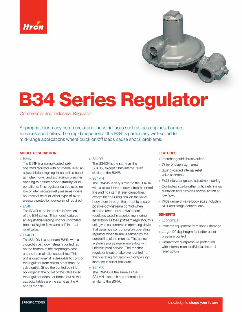
B34 Series RegulatorCommercial and Industrial Regulator
Appropriate for many commercial and industrial uses such as gas engines, burners, furnaces and boilers. The rapid response of the B34 is particularly well-suited for mid-range applications where quick on/off loads cause shock problems.
MODEL DESCRIPTION
» B34N The B34N is a spring-loaded, self-operated regulator with no internal relief, an adjustable loading ring for controlled boost at higher flows, and a precision breather opening to ensure proper stability for all conditions. This regulator can be used on low or intermediate inlet pressures where an internal relief or other type of over-pressure protection device is not required.
» B34R The B34R is the internal relief version of the B34 series. This model features an adjustable loading ring for controlled boost at higher flows and a 1" internal relief valve.
» B34DN The B34DN is a standard B34N with a closed-throat, downstream control tap on the bottom of the diaphragm case, and no internal relief capabilities. This unit is used when it is desirable to control the regulator from points other than the valve outlet. Since the control point is no longer at the outlet of the valve body, the regulator does not boost, but all the capacity tables are the same as the R and N models.
» B34DR The B34DR is the same as the B34DN, except it has internal relief similar to the B34R.
» B34MN The B34MN is very similar to the B34DN with a closed-throat, downstream control line and no internal relief capabilities, except for an O-ring seal on the valve body stem through the throat to assure positive downstream control when installed ahead of a downstream regulator. Used in a series monitoring installation as the upstream regulator, this unit gives customers an operating device that assumes control over an operating regulator when failure is sensed by the control line of the monitor. This series system assures maximum safety with uninterrupted service. The monitor regulator is set to take over control from the operating regulator with only a slight increase in outlet pressure.
» B34MR The B34MR is the same as the B34MN, except it has internal relief similar to the B34R.
FEATURES
» Interchangeable brass orifice
» 78 in2 of diaphragm area
» Spring-loaded internal relief valve assembly
» Field interchangeable adjustment spring
» Controlled size breather orifice eliminates pulsation and provides normal action at low flows
» Wide range of valve body sizes including NPT and flange connections
BENEFITS
» Economical
» Protects equipment from shock damage
» Large 12" diaphragm for better outlet pressure control
» Unmatched overpressure protection with internal monitor (IM) plus internal relief option
SPECIFICATIONS
2 B34 Commercial Series Regulator |
SHIPPING WEIGHT
One regulator per box Box weight: 24 lbs.
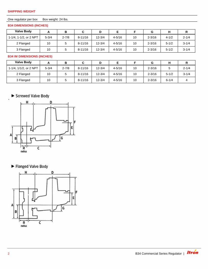
B34 DIMENSIONS (INCHES)
Valve Body A B C D E F G H R
1-1/4, 1-1/2, or 2 NPT 5-3/4 2-7/8 8-11/16 12-3/4 4-5/16 10 2-3/16 4-1/2 2-1/4
2 Flanged 10 5 8-11/16 12-3/4 4-5/16 10 2-3/16 5-1/2 3-1/4
3 Flanged 10 5 8-11/16 12-3/4 4-5/16 10 2-3/16 5-1/2 3-1/4
B34 IM DIMENSIONS (INCHES)
Valve Body A B C D E F G H R
1-1/4, 1/1/2, or 2 NPT 5-3/4 2-7/8 8-11/16 12-3/4 4-5/16 10 2-3/16 5 2-1/4
2 Flanged 10 5 8-11/16 12-3/4 4-5/16 10 2-3/16 5-1/2 3-1/4
3 Flanged 10 5 8-11/16 12-3/4 4-5/16 10 2-3/16 6-1/4 4
| B34 Commercial Series Regulator 3
SPRING DATA, SPRING COLOR OUTLET PRESSURE RANGE*
Models B34 N, R, M, D Models B34 IM, IMR, IMRV, IMN
Colors Part Number Outlet Pressure Range Colors Part Number Outlet Pressure Range
Orange 762341 3.0" w.c. - 5.0" w.c. Brown 762531 4.5" w.c. - 5.5" w.c.
Brown 762351 4.0" w.c. - 6.5" w.c. Green/white 762321 5.5" w.c. - 7.2" w.c.
Green (B34N, M, R) 762353 5.0" w.c. - 8.0" w.c. Black 762355
66
7.2" w.c. - 13.5" w.c.
Black 762355 6.5" w.c. - 13.0" w.c. Purple 762365 13.0" w.c. - 20.0" w.c.
Purple 762365 9.1" w.c. - 20.8" w.c. Blue/white 762358 0.6 PSIG – 1.2 PSIG
Blue (B34N, M, R) 762357 15.0" w.c. - 28.0" w.c. Silver/red 762323 0.8 PSIG - 2.2 PSIG
Silver (B34N, M, R) 762359 1.0 PSIG - 2.0 PSIG Yellow 762361 0.5 PSIG - 4.4 PSIG
Yellow 762361 2.0 PSIG – 4.5 PSIG Red-nested 762671 1.8 PSIG - 5.8 PSIG
Red-nested
85
762361
4.0 PSIG – 5.5 PSIG
White-nested 762673 4.8 PSIG – 7.3 PSIG
*Note Ranges are approximations, please contact manufacturer to obtain the best spring for your application.
ORIFICE DATA, WIDE OPEN FLOW COEFFICIENTS AND MAXIMUM PRESSURES
Orifice Size (inches)
K-Factor
Maximum Operating Inlet
(PSIG)
Maximum Emergency
Inlet Pressure (PSIG)
Maximum Emergency
Outlet Pressure (PSIG)
Inches w.c. Delivery
N & R Models
Inches w.c. Delivery
D & M Models
PSIG Delivery
All Models
All Deliveries
All Models
All Deliveries
All Models
1/4 125 125 175 175 300
60
1/4 x 3/8 125 125 125 175 300
3/8 290 125 125 175 300
3/8 x 1/2 305 125 125 150 300
1/2 500 75 125 150 300
1/2 x 5/8 550 60 125 150 300
5/8 700 60 125 150 300
5/8 x 3/4 750 60 100 150 300
3/4 900 60 100 150 300
3/4 x 7/8 950 60 100 150 230
7/8 1200 60 100 150 230
7/8 x 1 1245 25 100 150 230
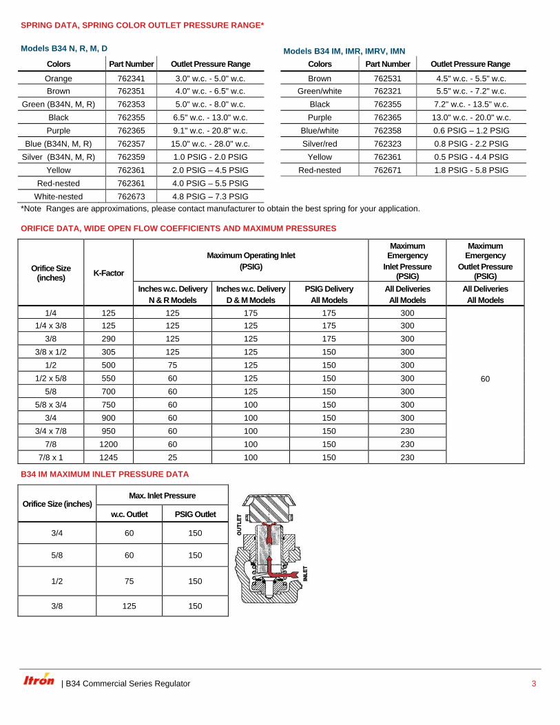
B34 IM MAXIMUM INLET PRESSURE DATA
Orifice Size (inches) Max. Inlet Pressure
w.c. Outlet PSIG Outlet
3/4 60 150
5/8 60 150
1/2 75 150
3/8 125 150
4 B34 Commercial Series Regulator |
B34 IM SPRING DATA
Spring Color Brown
(in. w.c.)
Green/White
(in. w.c.)
Black
(in. w.c.)
Purple
(in. w.c.)
Blue/White
(PSIG)
Silver/Red
(PSIG)
Yellow
(PSIG)
Red
(PSIG)
Outlet Pressure Range 4.5 - 5.5 5.5 - 7.2 7.2 - 13.5 13.0 - 20.0 0.6 – 1.2 0.8 - 2.2 0.5 - 4.4 1.8 - 5.8
B34 IMRV
Main Spring Color Outlet Pressure Set
Maximum Downstream Pressure Buildup
B34 IMRV
B34IMR & B34IMN Standard Relief Spring Brown/white Relief Spring Green Relief Spring
Brown 5.5" w.c. 10.5" w.c. 13.0" w.c. - -
Green/White 7.0" w.c. 11.5" w.c. 14.5" w.c. - -
Black 11.0" w.c. 16.0" w.c. 20.0" w.c. - -
Purple 14.0" w.c. 23.0" w.c. 28.0" w.c. - -
Blue 20.0" w.c. 26.0" w.c. 30.0" w.c. - -
Blue/white 1 PSIG 1.4 PSIG 1.5 PSIG 2.0 PSIG -
Silver/red 2 PSIG 2.5 PSIG 2.6 PSIG 3.2 PSIG -
Yellow 3 PSIG 3.7 PSIG 3.9 PSIG 5.0 PSIG 6.4 PSIG
Red 5 PSIG 6.1 PSIG 6.6 PSIG 8.0 PSIG 8.9 PSIG
B34 IMRV Flow Chart
Vented gas flow, regulator seat failed; monitor seat closed
Inlet Pressure PSIG 20 40 60 75 100 125
Flow SCFH 60 90 120 150 190 230
OPERATING TEMPERATURE RANGE
-20°F to 150°F
Silicone valve seats available for applications below -20°F
ADDITIONAL SPECIFICATIONS
Available Pilot Vent Sizes 1"
Loading Ring Position M & D Models: 0°
R & N Models for <1 PSIG set point: 21°; >1 PSIG set point: 0°
Other Available Options Seal wire to indicate unapproved tampering
1/8" pipe plug tap on upstream side of valve body
| B34 Commercial Series Regulator 5
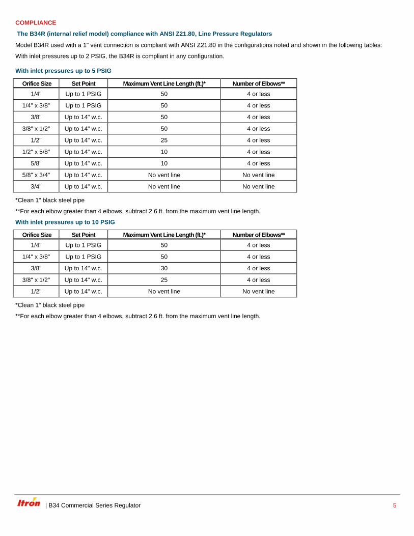
COMPLIANCE
The B34R (internal relief model) compliance with ANSI Z21.80, Line Pressure Regulators
Model B34R used with a 1" vent connection is compliant with ANSI Z21.80 in the configurations noted and shown in the following tables:
With inlet pressures up to 2 PSIG, the B34R is compliant in any configuration.
With inlet pressures up to 5 PSIG
Orifice Size Set Point Maximum Vent Line Length (ft.)* Number of Elbows**
1/4" Up to 1 PSIG 50 4 or less
1/4" x 3/8" Up to 1 PSIG 50 4 or less
3/8" Up to 14" w.c. 50 4 or less
3/8" x 1/2" Up to 14" w.c. 50 4 or less
1/2" Up to 14" w.c. 25 4 or less
1/2" x 5/8" Up to 14" w.c. 10 4 or less
5/8" Up to 14" w.c. 10 4 or less
5/8" x 3/4" Up to 14" w.c. No vent line No vent line
3/4" Up to 14" w.c. No vent line No vent line
*Clean 1" black steel pipe
**For each elbow greater than 4 elbows, subtract 2.6 ft. from the maximum vent line length.
With inlet pressures up to 10 PSIG
Orifice Size Set Point Maximum Vent Line Length (ft.)* Number of Elbows**
1/4" Up to 1 PSIG 50 4 or less
1/4" x 3/8" Up to 1 PSIG 50 4 or less
3/8" Up to 14" w.c. 30 4 or less
3/8" x 1/2" Up to 14" w.c. 25 4 or less
1/2" Up to 14" w.c. No vent line No vent line
*Clean 1" black steel pipe
**For each elbow greater than 4 elbows, subtract 2.6 ft. from the maximum vent line length.

6 B34 Commercial Series Regulator |
CONSTRUCTION
Itron takes pride in delivering American made products with the utmost concern for safety, quality, and customer satisfaction.
Construction material
Valve body High tensile strength cast iron
Orifice Brass
Valve seat Buna-N or silicone (for temperatures below -20°F)
Valve stem Plated steel
Lever pin Stainless steel
Lever Zinc and dichromate plated steel
Stem Guide Stainless steel
Upper diaphragm plate Zinc and dichromate plated steel
Lower diaphragm plate Die cast aluminum
Diaphragm Buna-N and nylon
Vent valve/seat Delrin/Buna-N
Vent screen Stainless steel
Adjustment ferrule Die cast aluminum
Seal cap Die cast aluminum
Diaphragm case Die cast aluminum
VALVE BODY SIZES (INCHES)
Inlet Outlet Screwed Flanged
1-1/4 1-1/4 X ---
1-1/4 1-1/2 X ---
1-1/4 2 X ---
1-1/2 1-1/2 X ---
1-1/2 2 X ---
2 2 X X
3 3 --- X
Note: X indicates that the valve body is available in that configuration.
B34 IM VALVE BODY SIZES (INCHES)
Inlet Outlet Screwed Flanged
1-1/4 1-1/2 X ---
1-1/4 2 X ---
1-1/2 1-1/2 X ---
1-1/2 2 X ---
2 2 X X
3 3 --- X*
*With 2" bore
Note: X indicates that the valve body is available in that configuration
| B34 Commercial Series Regulator 7
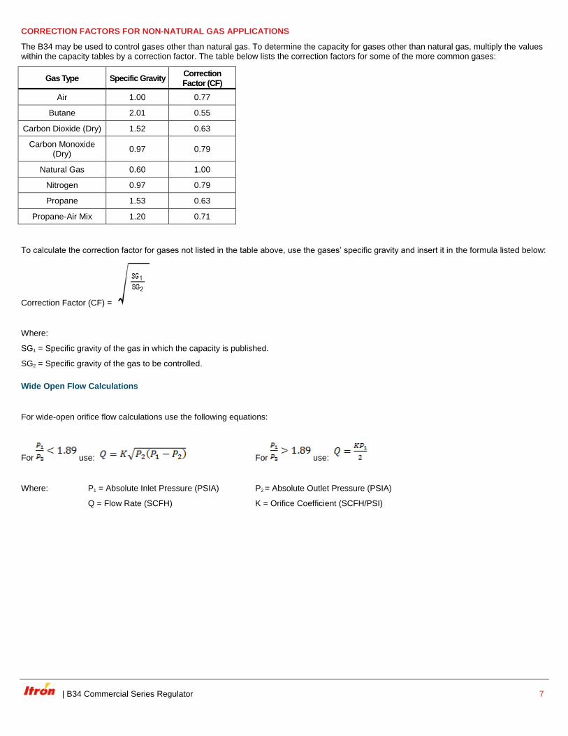
CORRECTION FACTORS FOR NON-NATURAL GAS APPLICATIONS
The B34 may be used to control gases other than natural gas. To determine the capacity for gases other than natural gas, multiply the values within the capacity tables by a correction factor. The table below lists the correction factors for some of the more common gases:
Gas Type Specific Gravity Correction Factor (CF)
Air 1.00 0.77
Butane 2.01 0.55
Carbon Dioxide (Dry) 1.52 0.63
Carbon Monoxide (Dry)
0.97 0.79
Natural Gas 0.60 1.00
Nitrogen 0.97 0.79
Propane 1.53 0.63
Propane-Air Mix 1.20 0.71
To calculate the correction factor for gases not listed in the table above, use the gases’ specific gravity and insert it in the formula listed below:
Correction Factor (CF) =
Where:
SG1 = Specific gravity of the gas in which the capacity is published.
SG2 = Specific gravity of the gas to be controlled.
Wide Open Flow Calculations
For wide-open orifice flow calculations use the following equations:
For use: For use:
Where: P1 = Absolute Inlet Pressure (PSIA) P2 = Absolute Outlet Pressure (PSIA)
Q = Flow Rate (SCFH) K = Orifice Coefficient (SCFH/PSI)

8 B34 Commercial Series Regulator |
B34 SERIES COMMERCIAL REGULATOR, MODELS N, R, M, AND D
7" w.c. (17.5 mbar) Capacity Table (1" w.c. Droop*)
Capacities in SCFH of 0.6 S.G. gas; base conditions of 14.7 PSIA and 60° F.
Typical Capacity Info. Inlet Pressure Orifice Size
Manufacturer Itron PSIG Bar 1/4" 1/4" x 3/8" 3/8" 3/8" x 1/2" 1/2"
Type and model B34R 8" w.c. 0.020 325 (9.1)
Regulator 10" w.c. 0.025 325 (9.1) 435 (12.2) 500 (14.0)
Inlet size: 2" NPT 12" w.c. 0.030 250 (7.0) 400 (11.2) 540 (15.1) 625 (17.5)
Outlet size: 2" NPT 14" w.c. 0.035 225 (6.3) 300 (8.4) 475 (13.3) 610 (17.1) 750 (21.0)
Position 11 16" w.c. 0.040 250 (7.0) 350 (9.8) 550 (15.4) 700 (19.6) 800 (22.4)
Spring color Green 18" w.c. 0.045 275 (7.7) 375 (10.5) 600 (16.8) 740 (20.7) 900 (25.2)
21" w.c. 0.052 300 (8.4) 400 (11.2) 700 (19.6) 800 (22.4) 1050 (29.4)
24" w.c. 0.060 350 (9.8) 400 (11.2) 800 (22.4) 890 (24.9) 1200 (33.6)
1 0.069 400 (11.2) 400 (11.2) 875 (24.5) 1000 (28.0) 1300 (36.4)
2 0.138 575 (16.1) 575 (16.1) 1300 (36.4) 1500 (42.0) 1900 (53.2)
3 0.207 775 (21.7) 800 (22.4) 1700 (47.6) 2000 (56.0) 2000 (56.0)
5 0.345 1000 (28.0) 1100 (30.8) 2000 (56.0) 2400 (67.2) 2400 (67.2)
10 0.69 1500 (42.5) 1700 (47.6) 3400 (95.2) 3500 (98.0) 3500 (98.0)
20 1.38 2150 (60.2) 2300 (64.4) 5000 (140.0) 5000 (140.0) 8500 (238.0)
30 2.07 2750 (77.0) 2900 (81.2) 6500 (182.0) 6500 (182.0) 10000 (280.0)
40 2.76 3450 (96.6) 3550 (99.4) 8000 (224.0) 8000 (224.0) 10000 (280.0)
50 3.45 3800 (106.4) 4100 (114.8) 9200 (257.6) 9200 (257.6) 10000 (280.0)
60 4.14 4500 (127.0) 5000 (140.0) 9500 (266.0) 10000 (280.0) 10000 (280.0)
70 4.83 4700 (131.6) 5100 (142.8) 10000 (280.0) 10000 (280.0) 10000 (280.0)
80 5.52 4900 (137.2) 6000 (169.9) 10000 (280.0)
90 6.21 6800 (190.4) 7000 (196.0) 10000 (280.0)
100 6.90 7400 (207.2) 7800 (218.4) 10000 (280.0)
125 8.63 8800 (246.4) 9000 (252.0) 10000 (280.0)
Inlet Effect A in. w.c. (mbar) 0.3 (0.8) 0.3 (0.8) 0.3 (0.8) 0.3 (0.8) 0.3 (0.8)
Lock UpB in. w.c. (mbar) 0.3 (0.8) 0.3 (0.8) 0.3 (0.8) 0.5 (1.3) 0.5 (1.3)
Notes:
*Individual regulator performance may vary from data shown.
A. Change in outlet pressure for 10 PSIG inlet pressure change.
B. Outlet pressure increase required for lock up.
Do not operate orifice in shaded inlet pressure area.
Inlet pressure is too low to deliver 7" w.c. (17.5 mbar).
| B34 Commercial Series Regulator 9
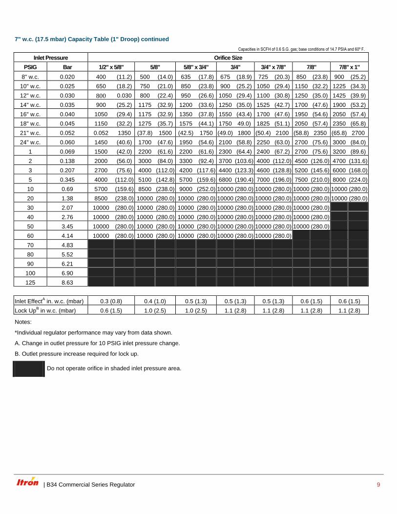
7" w.c. (17.5 mbar) Capacity Table (1" Droop) continued
Capacities in SCFH of 0.6 S.G. gas; base conditions of 14.7 PSIA and 60º F.
Inlet Pressure Orifice Size
PSIG Bar 1/2" x 5/8" 5/8" 5/8" x 3/4" 3/4" 3/4" x 7/8" 7/8" 7/8" x 1"
8" w.c. 0.020 400 (11.2) 500 (14.0) 635 (17.8) 675 (18.9) 725 (20.3) 850 (23.8) 900 (25.2)
10" w.c. 0.025 650 (18.2) 750 (21.0) 850 (23.8) 900 (25.2) 1050 (29.4) 1150 (32.2) 1225 (34.3)
12" w.c. 0.030 800 0.030 800 (22.4) 950 (26.6) 1050 (29.4) 1100 (30.8) 1250 (35.0) 1425 (39.9)
14" w.c. 0.035 900 (25.2) 1175 (32.9) 1200 (33.6) 1250 (35.0) 1525 (42.7) 1700 (47.6) 1900 (53.2)
16" w.c. 0.040 1050 (29.4) 1175 (32.9) 1350 (37.8) 1550 (43.4) 1700 (47.6) 1950 (54.6) 2050 (57.4)
18" w.c. 0.045 1150 (32.2) 1275 (35.7) 1575 (44.1) 1750 49.0) 1825 (51.1) 2050 (57.4) 2350 (65.8)
21" w.c. 0.052 0.052 1350 (37.8) 1500 (42.5) 1750 (49.0) 1800 (50.4) 2100 (58.8) 2350 (65.8) 2700
24" w.c. 0.060 1450 (40.6) 1700 (47.6) 1950 (54.6) 2100 (58.8) 2250 (63.0) 2700 (75.6) 3000 (84.0)
1 0.069 1500 (42.0) 2200 (61.6) 2200 (61.6) 2300 (64.4) 2400 (67.2) 2700 (75.6) 3200 (89.6)
2 0.138 2000 (56.0) 3000 (84.0) 3300 (92.4) 3700 (103.6) 4000 (112.0) 4500 (126.0) 4700 (131.6)
3 0.207 2700 (75.6) 4000 (112.0) 4200 (117.6) 4400 (123.3) 4600 (128.8) 5200 (145.6) 6000 (168.0)
5 0.345 4000 (112.0) 5100 (142.8) 5700 (159.6) 6800 (190.4) 7000 (196.0) 7500 (210.0) 8000 (224.0)
10 0.69 5700 (159.6) 8500 (238.0) 9000 (252.0) 10000 (280.0) 10000 (280.0) 10000 (280.0) 10000 (280.0)
20 1.38 8500 (238.0) 10000 (280.0) 10000 (280.0) 10000 (280.0) 10000 (280.0) 10000 (280.0) 10000 (280.0)
30 2.07 10000 (280.0) 10000 (280.0) 10000 (280.0) 10000 (280.0) 10000 (280.0) 10000 (280.0)
40 2.76 10000 (280.0) 10000 (280.0) 10000 (280.0) 10000 (280.0) 10000 (280.0) 10000 (280.0)
50 3.45 10000 (280.0) 10000 (280.0) 10000 (280.0) 10000 (280.0) 10000 (280.0) 10000 (280.0)
60 4.14 10000 (280.0) 10000 (280.0) 10000 (280.0) 10000 (280.0) 10000 (280.0)
70 4.83
80 5.52
90 6.21
100 6.90
125 8.63
Inlet EffectA in. w.c. (mbar) 0.3 (0.8) 0.4 (1.0) 0.5 (1.3) 0.5 (1.3) 0.5 (1.3) 0.6 (1.5) 0.6 (1.5)
Lock UpB in w.c. (mbar) 0.6 (1.5) 1.0 (2.5) 1.0 (2.5) 1.1 (2.8) 1.1 (2.8) 1.1 (2.8) 1.1 (2.8)
Notes:
*Individual regulator performance may vary from data shown.
A. Change in outlet pressure for 10 PSIG inlet pressure change.
B. Outlet pressure increase required for lock up.
Do not operate orifice in shaded inlet pressure area.

10 B34 Commercial Series Regulator |
B34 PERFORMANCE CURVES
7" w.c. Set Point
Type and model B34R
Outlet size 2" NPT
Orifice size 1/4" x 3/8"
Spring Green
All test results are reported at a base of 14.7 PSIA and 60º F. and with 0.6 S.G. gas.
B34 RELIEF CURVES
7" w.c. Set Point
B34R Relief Curves, Blocked Open, 7” w.c. Set Point
Inlet size 2" NPT
Outlet size 2" NPT
Vent size 1" NPT
All test results are reported at a base of 14.7 PSIA at 60º F and with 0.6 S.G. gas.
Regulator set at 7.0” w.c. with 40 PSIG inlet pressure at 200 SCFH.
| B34 Commercial Series Regulator 11
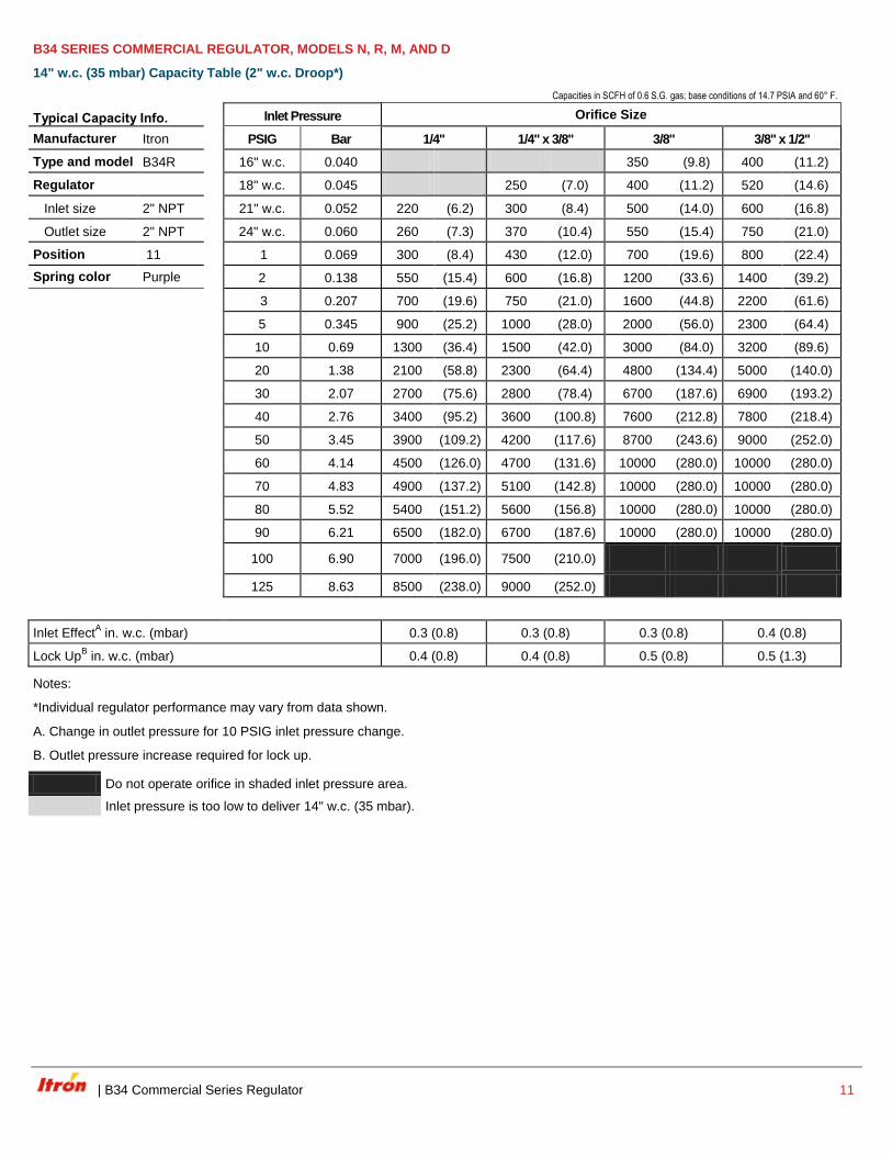
B34 SERIES COMMERCIAL REGULATOR, MODELS N, R, M, AND D
14" w.c. (35 mbar) Capacity Table (2" w.c. Droop*)
Capacities in SCFH of 0.6 S.G. gas; base conditions of 14.7 PSIA and 60° F.
Typical Capacity Info. Inlet Pressure Orifice Size
Manufacturer Itron PSIG Bar 1/4" 1/4" x 3/8" 3/8" 3/8" x 1/2"
Type and model B34R 16" w.c. 0.040 350 (9.8) 400 (11.2)
Regulator 18" w.c. 0.045 250 (7.0) 400 (11.2) 520 (14.6)
Inlet size 2" NPT 21" w.c. 0.052 220 (6.2) 300 (8.4) 500 (14.0) 600 (16.8)
Outlet size 2" NPT 24" w.c. 0.060 260 (7.3) 370 (10.4) 550 (15.4) 750 (21.0)
Position 11 1 0.069 300 (8.4) 430 (12.0) 700 (19.6) 800 (22.4)
Spring color Purple 2 0.138 550 (15.4) 600 (16.8) 1200 (33.6) 1400 (39.2)
3 0.207 700 (19.6) 750 (21.0) 1600 (44.8) 2200 (61.6)
5 0.345 900 (25.2) 1000 (28.0) 2000 (56.0) 2300 (64.4)
10 0.69 1300 (36.4) 1500 (42.0) 3000 (84.0) 3200 (89.6)
20 1.38 2100 (58.8) 2300 (64.4) 4800 (134.4) 5000 (140.0)
30 2.07 2700 (75.6) 2800 (78.4) 6700 (187.6) 6900 (193.2)
40 2.76 3400 (95.2) 3600 (100.8) 7600 (212.8) 7800 (218.4)
50 3.45 3900 (109.2) 4200 (117.6) 8700 (243.6) 9000 (252.0)
60 4.14 4500 (126.0) 4700 (131.6) 10000 (280.0) 10000 (280.0)
70 4.83 4900 (137.2) 5100 (142.8) 10000 (280.0) 10000 (280.0)
80 5.52 5400 (151.2) 5600 (156.8) 10000 (280.0) 10000 (280.0)
90 6.21 6500 (182.0) 6700 (187.6) 10000 (280.0) 10000 (280.0)
100 6.90 7000 (196.0) 7500 (210.0)
125 8.63 8500 (238.0) 9000 (252.0)
Inlet EffectA in. w.c. (mbar) 0.3 (0.8) 0.3 (0.8) 0.3 (0.8) 0.4 (0.8)
Lock UpB in. w.c. (mbar) 0.4 (0.8) 0.4 (0.8) 0.5 (0.8) 0.5 (1.3)
Notes:
*Individual regulator performance may vary from data shown.
A. Change in outlet pressure for 10 PSIG inlet pressure change.
B. Outlet pressure increase required for lock up.
Do not operate orifice in shaded inlet pressure area.
Inlet pressure is too low to deliver 14" w.c. (35 mbar).
12 B34 Commercial Series Regulator |
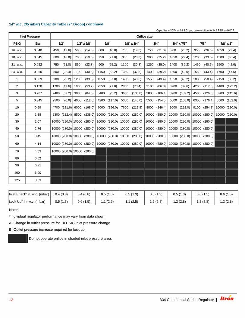
14" w.c. (35 mbar) Capacity Table (2" Droop) continued
Capacities in SCFH of 0.6 S.G. gas; base conditions of 14.7 PSIA and 60° F.
Inlet Pressure Orifice size
PSIG Bar 1/2" 1/2" x 5/8" 5/8" 5/8" x 3/4" 3/4" 3/4" x 7/8" 7/8" 7/8" x 1"
16" w.c. 0.040 450 (12.6) 500 (14.0) 600 (16.8) 700 (19.6) 750 (21.0) 900 (25.2) 950 (26.6) 1050 (29.4)
18" w.c. 0.045 600 (16.8) 700 (19.6) 750 (21.0) 850 (23.8) 900 (25.2) 1050 (29.4) 1200 (33.6) 1300 (36.4)
21" w.c. 0.052 750 (21.0) 850 (23.8) 900 (25.2) 1100 (30.8) 1250 (35.0) 1400 (39.2) 1450 (40.6) 1500 (42.0)
24" w.c. 0.060 800 (22.4) 1100 (30.8) 1150 (32.2) 1350 (37.8) 1400 (39.2) 1500 (42.0) 1550 (43.4) 1700 (47.6)
1 0.069 900 (25.2) 1200 (33.6) 1350 (37.8) 1450 (40.6) 1550 (43.4) 1650 (46.2) 1800 (50.4) 2150 (60.2)
2 0.138 1700 (47.6) 1900 (53.2) 2550 (71.0) 2800 (78.4) 3100 (86.8) 3200 (89.6) 4200 (117.6) 4400 (123.2)
3 0.207 2400 (67.2) 3000 (84.0) 3400 (95.2) 3600 (100.8) 3800 (106.4) 3900 (109.2) 4500 (126.0) 5200 (145.6)
5 0.345 2500 (70.0) 4000 (112.0) 4200 (117.6) 5000 (140.0) 5500 (154.0) 6000 (168.0) 6300 (176.4) 6500 (182.0)
10 0.69 4700 (131.6) 6000 (168.0) 7000 (196.0) 7600 (212.8) 8800 (246.4) 9000 (252.0) 9100 (254.8) 10000 (280.0)
20 1.38 8300 (232.4) 8500 (238.0) 10000 (280.0) 10000 (280.0) 10000 (280.0) 10000 (280.0) 10000 (280.0) 10000 (280.0)
30 2.07 10000 (280.0) 10000 (280.0) 10000 (280.0) 10000 (280.0) 10000 (280.0) 10000 (280.0) 10000 (280.0)
40 2.76 10000 (280.0) 10000 (280.0) 10000 (280.0) 10000 (280.0) 10000 (280.0) 10000 (280.0) 10000 (280.0)
50 3.45 10000 (280.0) 10000 (280.0) 10000 (280.0) 10000 (280.0) 10000 (280.0) 10000 (280.0) 10000 (280.0)
60 4.14 10000 (280.0) 10000 (280.0) 10000 (280.0) 10000 (280.0) 10000 (280.0) 10000 (280.0) 10000 (280.0)
70 4.83 10000 (280.0) 10000 (280.0)
80 5.52
90 6.21
100 6.90
125 8.63
Inlet EffectA in. w.c. (mbar) 0.4 (0.8) 0.4 (0.8) 0.5 (1.0) 0.5 (1.3) 0.5 (1.3) 0.5 (1.3) 0.6 (1.5) 0.6 (1.5)
Lock UpB in. w.c. (mbar) 0.5 (1.3) 0.6 (1.5) 1.1 (2.5) 1.1 (2.5) 1.2 (2.8) 1.2 (2.8) 1.2 (2.8) 1.2 (2.8)
Notes:
*Individual regulator performance may vary from data shown.
A. Change in outlet pressure for 10 PSIG inlet pressure change.
B. Outlet pressure increase required for lock up.
Do not operate orifice in shaded inlet pressure area.
| B34 Commercial Series Regulator 13
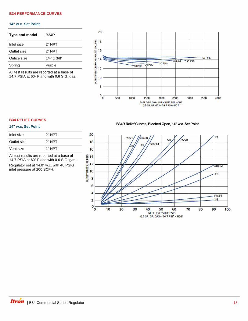
B34 PERFORMANCE CURVES
14" w.c. Set Point
Type and model B34R
Inlet size 2" NPT
Outlet size 2" NPT
Orifice size 1/4" x 3/8"
Spring Purple
All test results are reported at a base of 14.7 PSIA at 60º F and with 0.6 S.G. gas.
B34 RELIEF CURVES
14" w.c. Set Point
B34R Relief Curves, Blocked Open, 14” w.c. Set Point
Inlet size 2" NPT
Outlet size 2" NPT
Vent size 1" NPT
All test results are reported at a base of 14.7 PSIA at 60º F and with 0.6 S.G. gas.
Regulator set at 14.0” w.c. with 40 PSIG inlet pressure at 200 SCFH.
14 B34 Commercial Series Regulator |
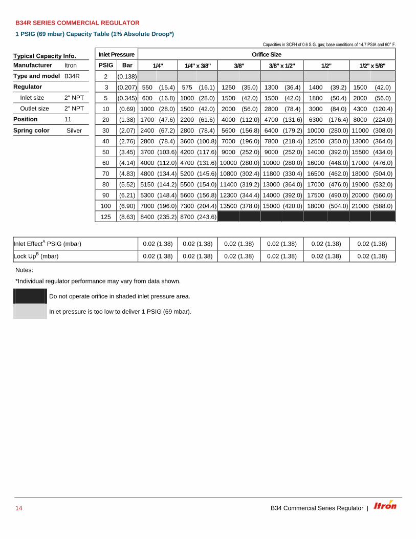
B34R SERIES COMMERCIAL REGULATOR
1 PSIG (69 mbar) Capacity Table (1% Absolute Droop*)
Capacities in SCFH of 0.6 S.G. gas; base conditions of 14.7 PSIA and 60° F.
Typical Capacity Info. Inlet Pressure Orifice Size
Manufacturer Itron
PSIG Bar 1/4" 1/4" x 3/8" 3/8" 3/8" x 1/2" 1/2" 1/2" x 5/8"
Type and model B34R 2 (0.138)
Regulator 3 (0.207) 550 (15.4) 575 (16.1) 1250 (35.0) 1300 (36.4) 1400 (39.2) 1500 (42.0)
Inlet size 2" NPT 5 (0.345) 600 (16.8) 1000 (28.0) 1500 (42.0) 1500 (42.0) 1800 (50.4) 2000 (56.0)
Outlet size 2" NPT 10 (0.69) 1000 (28.0) 1500 (42.0) 2000 (56.0) 2800 (78.4) 3000 (84.0) 4300 (120.4)
Position 11 20 (1.38) 1700 (47.6) 2200 (61.6) 4000 (112.0) 4700 (131.6) 6300 (176.4) 8000 (224.0)
Spring color Silver 30 (2.07) 2400 (67.2) 2800 (78.4) 5600 (156.8) 6400 (179.2) 10000 (280.0) 11000 (308.0)
40 (2.76) 2800 (78.4) 3600 (100.8) 7000 (196.0) 7800 (218.4) 12500 (350.0) 13000 (364.0)
50 (3.45) 3700 (103.6) 4200 (117.6) 9000 (252.0) 9000 (252.0) 14000 (392.0) 15500 (434.0)
60 (4.14) 4000 (112.0) 4700 (131.6) 10000 (280.0) 10000 (280.0) 16000 (448.0) 17000 (476.0)
70 (4.83) 4800 (134.4) 5200 (145.6) 10800 (302.4) 11800 (330.4) 16500 (462.0) 18000 (504.0)
80 (5.52) 5150 (144.2) 5500 (154.0) 11400 (319.2) 13000 (364.0) 17000 (476.0) 19000 (532.0)
90 (6.21) 5300 (148.4) 5600 (156.8) 12300 (344.4) 14000 (392.0) 17500 (490.0) 20000 (560.0)
100 (6.90) 7000 (196.0) 7300 (204.4) 13500 (378.0) 15000 (420.0) 18000 (504.0) 21000 (588.0)
125 (8.63) 8400 (235.2) 8700 (243.6)
Inlet EffectA PSIG (mbar) 0.02 (1.38) 0.02 (1.38) 0.02 (1.38) 0.02 (1.38) 0.02 (1.38) 0.02 (1.38)
Lock UpB (mbar) 0.02 (1.38) 0.02 (1.38) 0.02 (1.38) 0.02 (1.38) 0.02 (1.38) 0.02 (1.38)
Notes:
*Individual regulator performance may vary from data shown.
Do not operate orifice in shaded inlet pressure area.
Inlet pressure is too low to deliver 1 PSIG (69 mbar).
| B34 Commercial Series Regulator 15
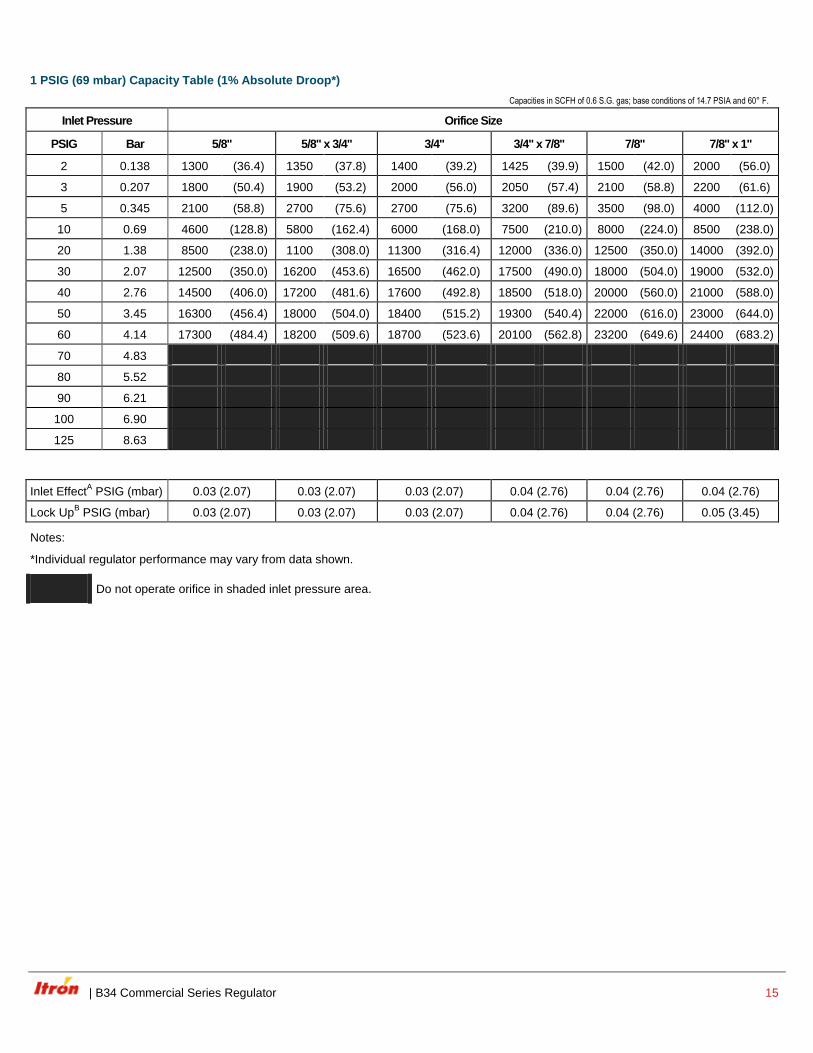
1 PSIG (69 mbar) Capacity Table (1% Absolute Droop*)
Capacities in SCFH of 0.6 S.G. gas; base conditions of 14.7 PSIA and 60° F.
Inlet Pressure Orifice Size
PSIG Bar 5/8" 5/8" x 3/4" 3/4" 3/4" x 7/8" 7/8" 7/8" x 1"
2 0.138 1300 (36.4) 1350 (37.8) 1400 (39.2) 1425 (39.9) 1500 (42.0) 2000 (56.0)
3 0.207 1800 (50.4) 1900 (53.2) 2000 (56.0) 2050 (57.4) 2100 (58.8) 2200 (61.6)
5 0.345 2100 (58.8) 2700 (75.6) 2700 (75.6) 3200 (89.6) 3500 (98.0) 4000 (112.0)
10 0.69 4600 (128.8) 5800 (162.4) 6000 (168.0) 7500 (210.0) 8000 (224.0) 8500 (238.0)
20 1.38 8500 (238.0) 1100 (308.0) 11300 (316.4) 12000 (336.0) 12500 (350.0) 14000 (392.0)
30 2.07 12500 (350.0) 16200 (453.6) 16500 (462.0) 17500 (490.0) 18000 (504.0) 19000 (532.0)
40 2.76 14500 (406.0) 17200 (481.6) 17600 (492.8) 18500 (518.0) 20000 (560.0) 21000 (588.0)
50 3.45 16300 (456.4) 18000 (504.0) 18400 (515.2) 19300 (540.4) 22000 (616.0) 23000 (644.0)
60 4.14 17300 (484.4) 18200 (509.6) 18700 (523.6) 20100 (562.8) 23200 (649.6) 24400 (683.2)
70 4.83
80 5.52
90 6.21
100 6.90
125 8.63
Inlet EffectA PSIG (mbar) 0.03 (2.07) 0.03 (2.07) 0.03 (2.07) 0.04 (2.76) 0.04 (2.76) 0.04 (2.76)
Lock UpB PSIG (mbar) 0.03 (2.07) 0.03 (2.07) 0.03 (2.07) 0.04 (2.76) 0.04 (2.76) 0.05 (3.45)
Notes:
*Individual regulator performance may vary from data shown.
Do not operate orifice in shaded inlet pressure area.
16 B34 Commercial Series Regulator |
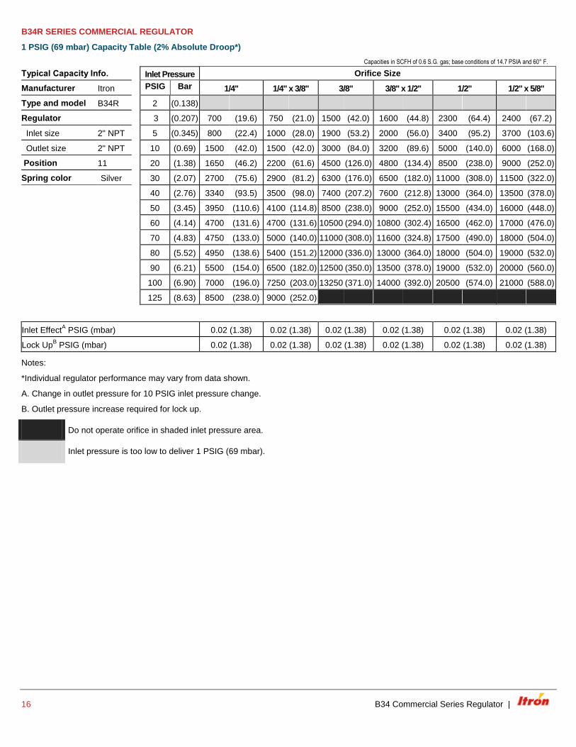
B34R SERIES COMMERCIAL REGULATOR
1 PSIG (69 mbar) Capacity Table (2% Absolute Droop*)
Capacities in SCFH of 0.6 S.G. gas; base conditions of 14.7 PSIA and 60° F.
Typical Capacity Info. Inlet Pressure Orifice Size
Manufacturer Itron PSIG Bar 1/4" 1/4" x 3/8" 3/8" 3/8" x 1/2" 1/2" 1/2" x 5/8"
Type and model B34R 2 (0.138)
Regulator 3 (0.207) 700 (19.6) 750 (21.0) 1500 (42.0) 1600 (44.8) 2300 (64.4) 2400 (67.2)
Inlet size 2" NPT 5 (0.345) 800 (22.4) 1000 (28.0) 1900 (53.2) 2000 (56.0) 3400 (95.2) 3700 (103.6)
Outlet size 2" NPT 10 (0.69) 1500 (42.0) 1500 (42.0) 3000 (84.0) 3200 (89.6) 5000 (140.0) 6000 (168.0)
Position 11 20 (1.38) 1650 (46.2) 2200 (61.6) 4500 (126.0) 4800 (134.4) 8500 (238.0) 9000 (252.0)
Spring color Silver 30 (2.07) 2700 (75.6) 2900 (81.2) 6300 (176.0) 6500 (182.0) 11000 (308.0) 11500 (322.0)
40 (2.76) 3340 (93.5) 3500 (98.0) 7400 (207.2) 7600 (212.8) 13000 (364.0) 13500 (378.0)
50 (3.45) 3950 (110.6) 4100 (114.8) 8500 (238.0) 9000 (252.0) 15500 (434.0) 16000 (448.0)
60 (4.14) 4700 (131.6) 4700 (131.6) 10500 (294.0) 10800 (302.4) 16500 (462.0) 17000 (476.0)
70 (4.83) 4750 (133.0) 5000 (140.0) 11000 (308.0) 11600 (324.8) 17500 (490.0) 18000 (504.0)
80 (5.52) 4950 (138.6) 5400 (151.2) 12000 (336.0) 13000 (364.0) 18000 (504.0) 19000 (532.0)
90 (6.21) 5500 (154.0) 6500 (182.0) 12500 (350.0) 13500 (378.0) 19000 (532.0) 20000 (560.0)
100 (6.90) 7000 (196.0) 7250 (203.0) 13250 (371.0) 14000 (392.0) 20500 (574.0) 21000 (588.0)
125 (8.63) 8500 (238.0) 9000 (252.0)
Inlet EffectA PSIG (mbar) 0.02 (1.38) 0.02 (1.38) 0.02 (1.38) 0.02 (1.38) 0.02 (1.38) 0.02 (1.38)
Lock UpB PSIG (mbar) 0.02 (1.38) 0.02 (1.38) 0.02 (1.38) 0.02 (1.38) 0.02 (1.38) 0.02 (1.38)
Notes:
*Individual regulator performance may vary from data shown.
A. Change in outlet pressure for 10 PSIG inlet pressure change.
B. Outlet pressure increase required for lock up.
Do not operate orifice in shaded inlet pressure area.
Inlet pressure is too low to deliver 1 PSIG (69 mbar).
| B34 Commercial Series Regulator 17
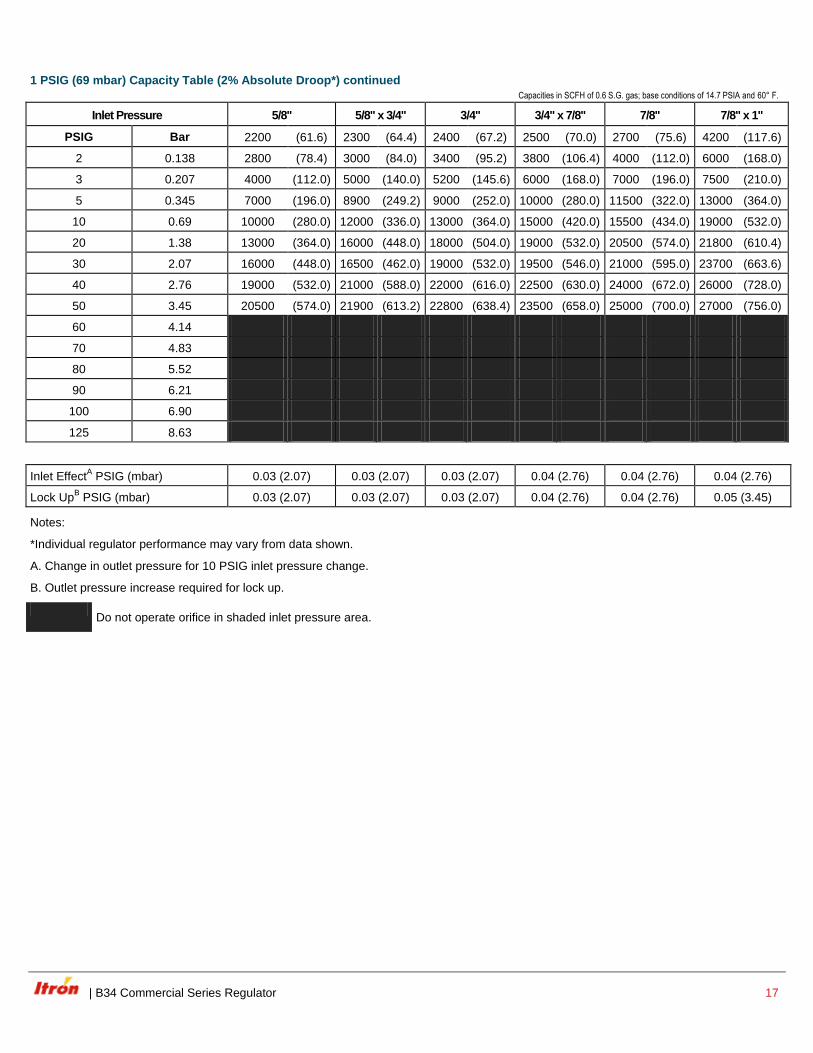
1 PSIG (69 mbar) Capacity Table (2% Absolute Droop*) continued
Capacities in SCFH of 0.6 S.G. gas; base conditions of 14.7 PSIA and 60° F.
Inlet Pressure 5/8" 5/8" x 3/4" 3/4" 3/4" x 7/8" 7/8" 7/8" x 1"
PSIG Bar 2200 (61.6) 2300 (64.4) 2400 (67.2) 2500 (70.0) 2700 (75.6) 4200 (117.6)
2 0.138 2800 (78.4) 3000 (84.0) 3400 (95.2) 3800 (106.4) 4000 (112.0) 6000 (168.0)
3 0.207 4000 (112.0) 5000 (140.0) 5200 (145.6) 6000 (168.0) 7000 (196.0) 7500 (210.0)
5 0.345 7000 (196.0) 8900 (249.2) 9000 (252.0) 10000 (280.0) 11500 (322.0) 13000 (364.0)
10 0.69 10000 (280.0) 12000 (336.0) 13000 (364.0) 15000 (420.0) 15500 (434.0) 19000 (532.0)
20 1.38 13000 (364.0) 16000 (448.0) 18000 (504.0) 19000 (532.0) 20500 (574.0) 21800 (610.4)
30 2.07 16000 (448.0) 16500 (462.0) 19000 (532.0) 19500 (546.0) 21000 (595.0) 23700 (663.6)
40 2.76 19000 (532.0) 21000 (588.0) 22000 (616.0) 22500 (630.0) 24000 (672.0) 26000 (728.0)
50 3.45 20500 (574.0) 21900 (613.2) 22800 (638.4) 23500 (658.0) 25000 (700.0) 27000 (756.0)
60 4.14
70 4.83
80 5.52
90 6.21
100 6.90
125 8.63
Inlet EffectA PSIG (mbar) 0.03 (2.07) 0.03 (2.07) 0.03 (2.07) 0.04 (2.76) 0.04 (2.76) 0.04 (2.76)
Lock UpB PSIG (mbar) 0.03 (2.07) 0.03 (2.07) 0.03 (2.07) 0.04 (2.76) 0.04 (2.76) 0.05 (3.45)
Notes:
*Individual regulator performance may vary from data shown.
A. Change in outlet pressure for 10 PSIG inlet pressure change.
B. Outlet pressure increase required for lock up.
Do not operate orifice in shaded inlet pressure area.
18 B34 Commercial Series Regulator |
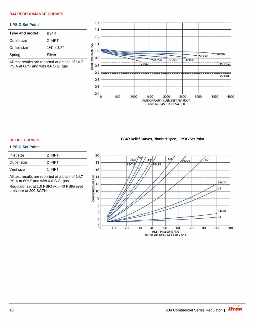
B34 PERFORMANCE CURVES
1 PSIG Set Point
Type and model B34R
Outlet size 2" NPT
Orifice size 1/4" x 3/8"
Spring Silver
All test results are reported at a base of 14.7 PSIA at 60ºF and with 0.6 S.G. gas.
RELIEF CURVES
1 PSIG Set Point
B34R Relief Curves, Blocked Open, 1 PSIG Set Point
Inlet size 2" NPT
Outlet size 2" NPT
Vent size 1" NPT
All test results are reported at a base of 14.7 PSIA at 60º F and with 0.6 S.G. gas.
Regulator set at 1.0 PSIG with 40 PSIG inlet pressure at 200 SCFH.
| B34 Commercial Series Regulator 19
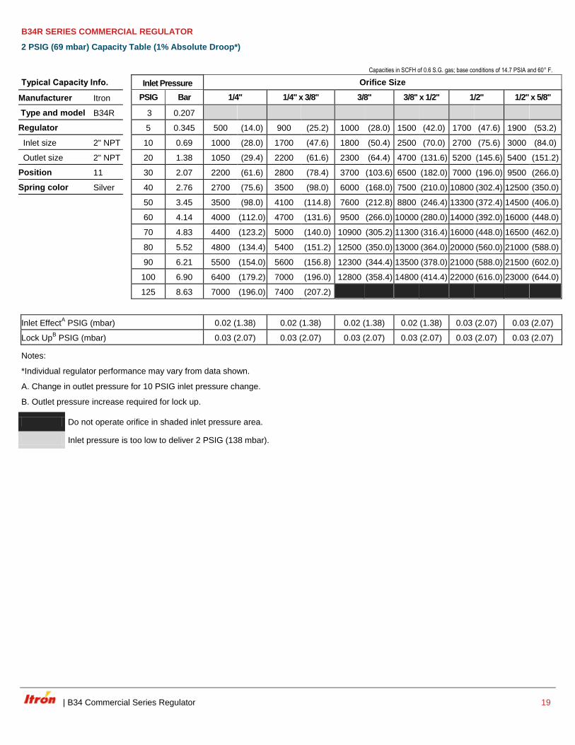
B34R SERIES COMMERCIAL REGULATOR
2 PSIG (69 mbar) Capacity Table (1% Absolute Droop*)
Capacities in SCFH of 0.6 S.G. gas; base conditions of 14.7 PSIA and 60° F.
Typical Capacity Info. Inlet Pressure Orifice Size
Manufacturer Itron PSIG Bar 1/4" 1/4" x 3/8" 3/8" 3/8" x 1/2" 1/2" 1/2" x 5/8"
Type and model B34R 3 0.207
Regulator 5 0.345 500 (14.0) 900 (25.2) 1000 (28.0) 1500 (42.0) 1700 (47.6) 1900 (53.2)
Inlet size 2" NPT 10 0.69 1000 (28.0) 1700 (47.6) 1800 (50.4) 2500 (70.0) 2700 (75.6) 3000 (84.0)
Outlet size 2" NPT 20 1.38 1050 (29.4) 2200 (61.6) 2300 (64.4) 4700 (131.6) 5200 (145.6) 5400 (151.2)
Position 11 30 2.07 2200 (61.6) 2800 (78.4) 3700 (103.6) 6500 (182.0) 7000 (196.0) 9500 (266.0)
Spring color Silver 40 2.76 2700 (75.6) 3500 (98.0) 6000 (168.0) 7500 (210.0) 10800 (302.4) 12500 (350.0)
50 3.45 3500 (98.0) 4100 (114.8) 7600 (212.8) 8800 (246.4) 13300 (372.4) 14500 (406.0)
60 4.14 4000 (112.0) 4700 (131.6) 9500 (266.0) 10000 (280.0) 14000 (392.0) 16000 (448.0)
70 4.83 4400 (123.2) 5000 (140.0) 10900 (305.2) 11300 (316.4) 16000 (448.0) 16500 (462.0)
80 5.52 4800 (134.4) 5400 (151.2) 12500 (350.0) 13000 (364.0) 20000 (560.0) 21000 (588.0)
90 6.21 5500 (154.0) 5600 (156.8) 12300 (344.4) 13500 (378.0) 21000 (588.0) 21500 (602.0)
100 6.90 6400 (179.2) 7000 (196.0) 12800 (358.4) 14800 (414.4) 22000 (616.0) 23000 (644.0)
125 8.63 7000 (196.0) 7400 (207.2)
Inlet EffectA PSIG (mbar) 0.02 (1.38) 0.02 (1.38) 0.02 (1.38) 0.02 (1.38) 0.03 (2.07) 0.03 (2.07)
Lock UpB PSIG (mbar) 0.03 (2.07) 0.03 (2.07) 0.03 (2.07) 0.03 (2.07) 0.03 (2.07) 0.03 (2.07)
Notes:
*Individual regulator performance may vary from data shown.
A. Change in outlet pressure for 10 PSIG inlet pressure change.
B. Outlet pressure increase required for lock up.
Do not operate orifice in shaded inlet pressure area.
Inlet pressure is too low to deliver 2 PSIG (138 mbar).
20 B34 Commercial Series Regulator |
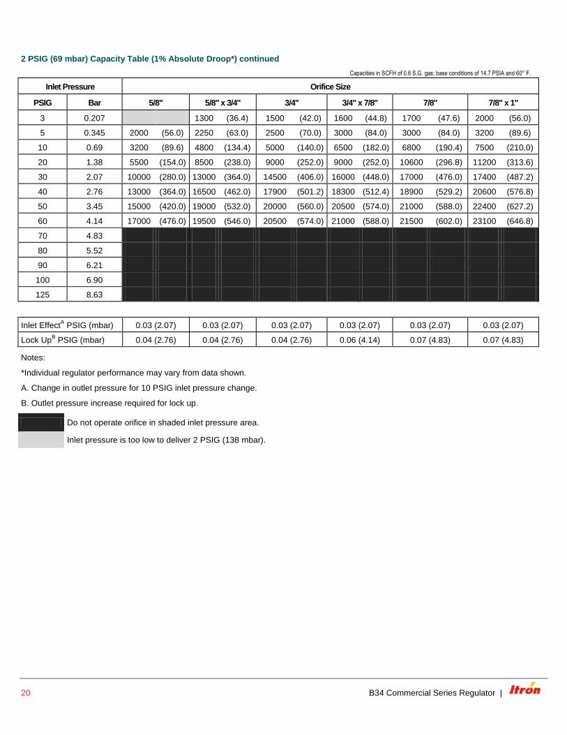
2 PSIG (69 mbar) Capacity Table (1% Absolute Droop*) continued
Capacities in SCFH of 0.6 S.G. gas; base conditions of 14.7 PSIA and 60° F.
Inlet Pressure Orifice Size
PSIG Bar 5/8" 5/8" x 3/4" 3/4" 3/4" x 7/8" 7/8" 7/8" x 1"
3 0.207 1300 (36.4) 1500 (42.0) 1600 (44.8) 1700 (47.6) 2000 (56.0)
5 0.345 2000 (56.0) 2250 (63.0) 2500 (70.0) 3000 (84.0) 3000 (84.0) 3200 (89.6)
10 0.69 3200 (89.6) 4800 (134.4) 5000 (140.0) 6500 (182.0) 6800 (190.4) 7500 (210.0)
20 1.38 5500 (154.0) 8500 (238.0) 9000 (252.0) 9000 (252.0) 10600 (296.8) 11200 (313.6)
30 2.07 10000 (280.0) 13000 (364.0) 14500 (406.0) 16000 (448.0) 17000 (476.0) 17400 (487.2)
40 2.76 13000 (364.0) 16500 (462.0) 17900 (501.2) 18300 (512.4) 18900 (529.2) 20600 (576.8)
50 3.45 15000 (420.0) 19000 (532.0) 20000 (560.0) 20500 (574.0) 21000 (588.0) 22400 (627.2)
60 4.14 17000 (476.0) 19500 (546.0) 20500 (574.0) 21000 (588.0) 21500 (602.0) 23100 (646.8)
70 4.83
80 5.52
90 6.21
100 6.90
125 8.63
Inlet EffectA PSIG (mbar) 0.03 (2.07) 0.03 (2.07) 0.03 (2.07) 0.03 (2.07) 0.03 (2.07) 0.03 (2.07)
Lock UpB PSIG (mbar) 0.04 (2.76) 0.04 (2.76) 0.04 (2.76) 0.06 (4.14) 0.07 (4.83) 0.07 (4.83)
Notes:
*Individual regulator performance may vary from data shown.
A. Change in outlet pressure for 10 PSIG inlet pressure change.
B. Outlet pressure increase required for lock up.
Do not operate orifice in shaded inlet pressure area.
Inlet pressure is too low to deliver 2 PSIG (138 mbar).
| B34 Commercial Series Regulator 21
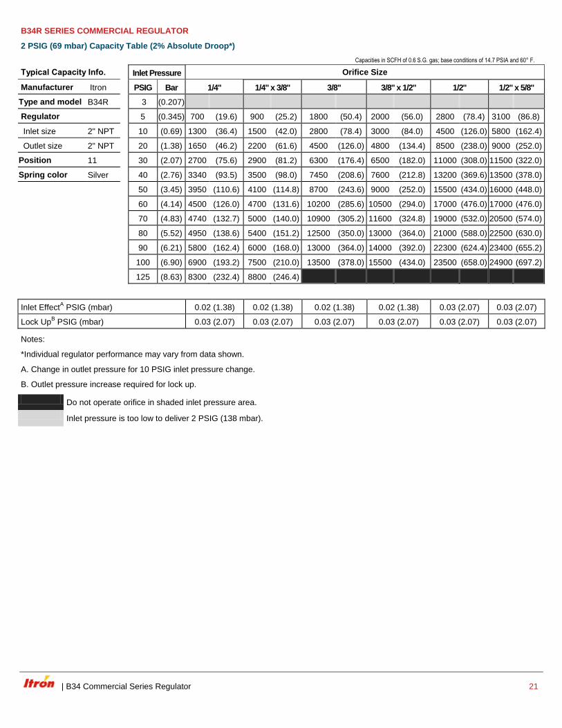
B34R SERIES COMMERCIAL REGULATOR
2 PSIG (69 mbar) Capacity Table (2% Absolute Droop*)
Capacities in SCFH of 0.6 S.G. gas; base conditions of 14.7 PSIA and 60° F.
Typical Capacity Info. Inlet Pressure Orifice Size
Manufacturer Itron PSIG Bar 1/4" 1/4" x 3/8" 3/8" 3/8" x 1/2" 1/2" 1/2" x 5/8"
Type and model B34R 3 (0.207)
Regulator 5 (0.345) 700 (19.6) 900 (25.2) 1800 (50.4) 2000 (56.0) 2800 (78.4) 3100 (86.8)
Inlet size 2" NPT 10 (0.69) 1300 (36.4) 1500 (42.0) 2800 (78.4) 3000 (84.0) 4500 (126.0) 5800 (162.4)
Outlet size 2" NPT 20 (1.38) 1650 (46.2) 2200 (61.6) 4500 (126.0) 4800 (134.4) 8500 (238.0) 9000 (252.0)
Position 11 30 (2.07) 2700 (75.6) 2900 (81.2) 6300 (176.4) 6500 (182.0) 11000 (308.0) 11500 (322.0)
Spring color Silver 40 (2.76) 3340 (93.5) 3500 (98.0) 7450 (208.6) 7600 (212.8) 13200 (369.6) 13500 (378.0)
50 (3.45) 3950 (110.6) 4100 (114.8) 8700 (243.6) 9000 (252.0) 15500 (434.0) 16000 (448.0)
60 (4.14) 4500 (126.0) 4700 (131.6) 10200 (285.6) 10500 (294.0) 17000 (476.0) 17000 (476.0)
70 (4.83) 4740 (132.7) 5000 (140.0) 10900 (305.2) 11600 (324.8) 19000 (532.0) 20500 (574.0)
80 (5.52) 4950 (138.6) 5400 (151.2) 12500 (350.0) 13000 (364.0) 21000 (588.0) 22500 (630.0)
90 (6.21) 5800 (162.4) 6000 (168.0) 13000 (364.0) 14000 (392.0) 22300 (624.4) 23400 (655.2)
100 (6.90) 6900 (193.2) 7500 (210.0) 13500 (378.0) 15500 (434.0) 23500 (658.0) 24900 (697.2)
125 (8.63) 8300 (232.4) 8800 (246.4)
Inlet EffectA PSIG (mbar) 0.02 (1.38) 0.02 (1.38) 0.02 (1.38) 0.02 (1.38) 0.03 (2.07) 0.03 (2.07)
Lock UpB PSIG (mbar) 0.03 (2.07) 0.03 (2.07) 0.03 (2.07) 0.03 (2.07) 0.03 (2.07) 0.03 (2.07)
Notes:
*Individual regulator performance may vary from data shown.
A. Change in outlet pressure for 10 PSIG inlet pressure change.
B. Outlet pressure increase required for lock up.
Do not operate orifice in shaded inlet pressure area.
Inlet pressure is too low to deliver 2 PSIG (138 mbar).

22 B34 Commercial Series Regulator |
2 PSIG (69 mbar) Capacity Table (2% Absolute Droop*) continued
Capacities in SCFH of 0.6 S.G. gas; base conditions of 14.7 PSIA and 60° F.
Input Pressure Orifice Size
PSIG Bar 5/8" 5/8" x 3/4" 3/4" 3/4" x 7/8" 7/8" 7/8" x 1"
3 0.207 2500 (70.0) 2800 (78.4) 3500 (98.0) 3700 (103.6) 4000 (112.0)
5 0.345 3200 (89.6) 3600 (100.8) 4100 (114.8) 5000 (140.0) 5000 (140.0) 6000 (168.0)
10 0.69 6000 (168.0) 7000 (196.0) 7500 (210.0) 9500 (266.0) 9800 (274.4) 12000 (336.0)
20 1.38 10000 (280.0) 12000 (336.0) 13000 (364.0) 14000 (392.0) 15500 (434.0) 19000 (532.0)
30 2.07 13000 (364.0) 16000 (448.0) 18500 (518.0) 19500 (546.0) 20500 (574.0) 21800 (610.4)
40 2.76 16000 (448.0) 19000 (532.0) 20000 (560.0) 21000 (588.0) 22000 (616.0) 23700 (663.6)
50 3.45 20500 (574.0) 21000 (588.0) 24000 (672.0) 25000 (700.0) 26500 (742.0) 27500 (770.0)
60 4.14 21300 (596.4) 22800 (638.4) 25700 (719.6) 26400 (739.2) 28000 (784.0) 28300 (792.4)
70 4.83
80 5.52
90 6.21
100 6.90
125 8.63
Inlet EffectA PSIG (mbar) 0.03 (2.07) 0.03 (2.07) 0.03 (2.07) 0.03 (2.07) 0.03 (2.07) 0.03 (2.07)
Lock UpB PSIG (mbar) 0.04 (2.76) 0.04 (2.76) 0.04 (2.76) 0.06 (4.14) 0.07 (4.83) 0.07 (4.83)
Notes:
*Individual regulator performance may vary from data shown.
A. Change in outlet pressure for 10 PSIG inlet pressure change.
B. Outlet pressure increase required for lock up.
Do not operate orifice in shaded inlet pressure area.
Inlet pressure is too low to deliver 2 PSIG (138 mbar).
| B34 Commercial Series Regulator 23
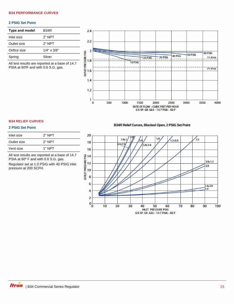
B34 PERFORMANCE CURVES
2 PSIG Set Point
Type and model B34R
Inlet size 2" NPT
Outlet size 2" NPT
Orifice size 1/4" x 3/8"
Spring Silver
All test results are reported at a base of 14.7 PSIA at 60ºF and with 0.6 S.G. gas.
B34 RELIEF CURVES
2 PSIG Set Point
B34R Relief Curves, Blocked Open, 2 PSIG Set Point
Inlet size 2" NPT
Outlet size 2" NPT
Vent size 1" NPT
All test results are reported at a base of 14.7 PSIA at 60º F and with 0.6 S.G. gas.
Regulator set at 1.0 PSIG with 40 PSIG inlet pressure at 200 SCFH.
24 B34 Commercial Series Regulator |
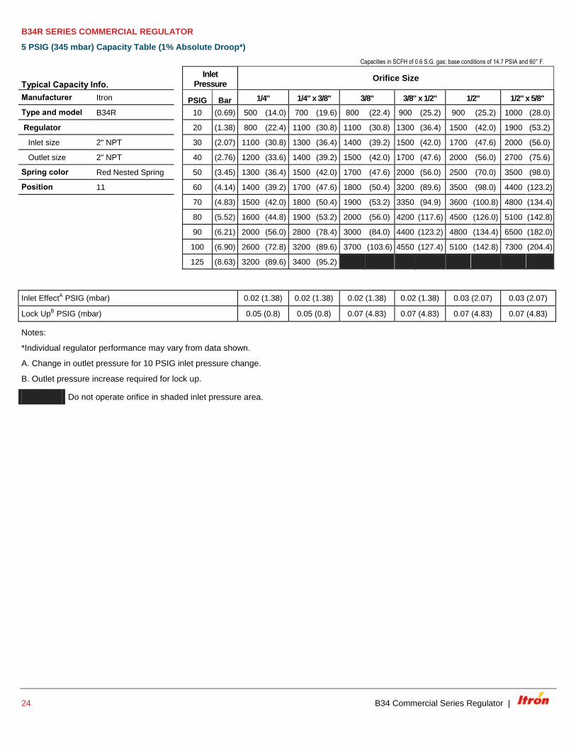
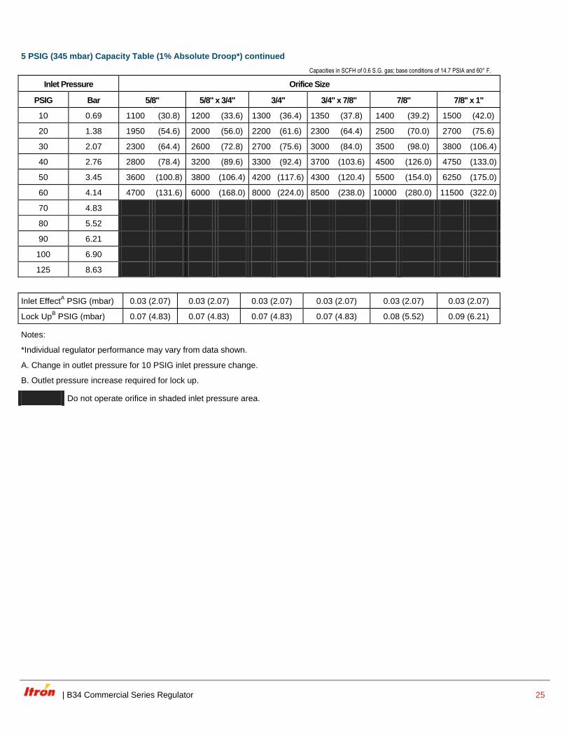
B34R SERIES COMMERCIAL REGULATOR
5 PSIG (345 mbar) Capacity Table (1% Absolute Droop*)
Capacities in SCFH of 0.6 S.G. gas; base conditions of 14.7 PSIA and 60° F.
Typical Capacity Info.
Inlet Pressure
Orifice Size
Manufacturer Itron PSIG Bar 1/4" 1/4" x 3/8" 3/8" 3/8" x 1/2" 1/2" 1/2" x 5/8"
Type and model B34R 10 (0.69) 500 (14.0) 700 (19.6) 800 (22.4) 900 (25.2) 900 (25.2) 1000 (28.0)
Regulator 20 (1.38) 800 (22.4) 1100 (30.8) 1100 (30.8) 1300 (36.4) 1500 (42.0) 1900 (53.2)
Inlet size 2" NPT 30 (2.07) 1100 (30.8) 1300 (36.4) 1400 (39.2) 1500 (42.0) 1700 (47.6) 2000 (56.0)
Outlet size 2" NPT 40 (2.76) 1200 (33.6) 1400 (39.2) 1500 (42.0) 1700 (47.6) 2000 (56.0) 2700 (75.6)
Spring color Red Nested Spring 50 (3.45) 1300 (36.4) 1500 (42.0) 1700 (47.6) 2000 (56.0) 2500 (70.0) 3500 (98.0)
Position 11 60 (4.14) 1400 (39.2) 1700 (47.6) 1800 (50.4) 3200 (89.6) 3500 (98.0) 4400 (123.2)
70 (4.83) 1500 (42.0) 1800 (50.4) 1900 (53.2) 3350 (94.9) 3600 (100.8) 4800 (134.4)
80 (5.52) 1600 (44.8) 1900 (53.2) 2000 (56.0) 4200 (117.6) 4500 (126.0) 5100 (142.8)
90 (6.21) 2000 (56.0) 2800 (78.4) 3000 (84.0) 4400 (123.2) 4800 (134.4) 6500 (182.0)
100 (6.90) 2600 (72.8) 3200 (89.6) 3700 (103.6) 4550 (127.4) 5100 (142.8) 7300 (204.4)
125 (8.63) 3200 (89.6) 3400 (95.2)
Inlet EffectA PSIG (mbar) 0.02 (1.38) 0.02 (1.38) 0.02 (1.38) 0.02 (1.38) 0.03 (2.07) 0.03 (2.07)
Lock UpB PSIG (mbar) 0.05 (0.8) 0.05 (0.8) 0.07 (4.83) 0.07 (4.83) 0.07 (4.83) 0.07 (4.83)
Notes:
*Individual regulator performance may vary from data shown.
A. Change in outlet pressure for 10 PSIG inlet pressure change.
B. Outlet pressure increase required for lock up.
Do not operate orifice in shaded inlet pressure area.
| B34 Commercial Series Regulator 25
5 PSIG (345 mbar) Capacity Table (1% Absolute Droop*) continued
Capacities in SCFH of 0.6 S.G. gas; base conditions of 14.7 PSIA and 60° F.
Inlet Pressure Orifice Size
PSIG Bar 5/8" 5/8" x 3/4" 3/4" 3/4" x 7/8" 7/8" 7/8" x 1"
10 0.69 1100 (30.8) 1200 (33.6) 1300 (36.4) 1350 (37.8) 1400 (39.2) 1500 (42.0)
20 1.38 1950 (54.6) 2000 (56.0) 2200 (61.6) 2300 (64.4) 2500 (70.0) 2700 (75.6)
30 2.07 2300 (64.4) 2600 (72.8) 2700 (75.6) 3000 (84.0) 3500 (98.0) 3800 (106.4)
40 2.76 2800 (78.4) 3200 (89.6) 3300 (92.4) 3700 (103.6) 4500 (126.0) 4750 (133.0)
50 3.45 3600 (100.8) 3800 (106.4) 4200 (117.6) 4300 (120.4) 5500 (154.0) 6250 (175.0)
60 4.14 4700 (131.6) 6000 (168.0) 8000 (224.0) 8500 (238.0) 10000 (280.0) 11500 (322.0)
70 4.83
80 5.52
90 6.21
100 6.90
125 8.63
Inlet EffectA PSIG (mbar) 0.03 (2.07) 0.03 (2.07) 0.03 (2.07) 0.03 (2.07) 0.03 (2.07) 0.03 (2.07)
Lock UpB PSIG (mbar) 0.07 (4.83) 0.07 (4.83) 0.07 (4.83) 0.07 (4.83) 0.08 (5.52) 0.09 (6.21)
Notes:
*Individual regulator performance may vary from data shown.
A. Change in outlet pressure for 10 PSIG inlet pressure change.
B. Outlet pressure increase required for lock up.
Do not operate orifice in shaded inlet pressure area.
26 B34 Commercial Series Regulator |
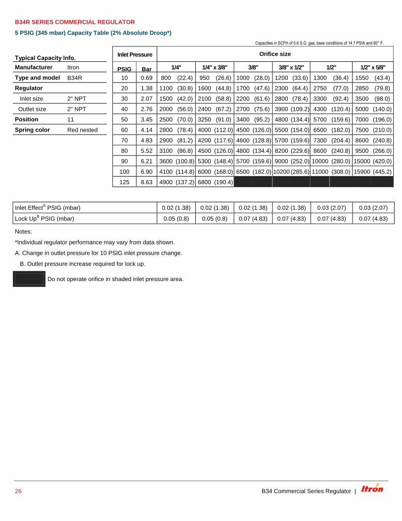
B34R SERIES COMMERCIAL REGULATOR
5 PSIG (345 mbar) Capacity Table (2% Absolute Droop*)
Capacities in SCFH of 0.6 S.G. gas; base conditions of 14.7 PSIA and 60° F.
Typical Capacity Info. Inlet Pressure Orifice size
Manufacturer Itron PSIG Bar 1/4" 1/4" x 3/8" 3/8" 3/8" x 1/2" 1/2" 1/2" x 5/8"
Type and model B34R 10 0.69 800 (22.4) 950 (26.6) 1000 (28.0) 1200 (33.6) 1300 (36.4) 1550 (43.4)
Regulator 20 1.38 1100 (30.8) 1600 (44.8) 1700 (47.6) 2300 (64.4) 2750 (77.0) 2850 (79.8)
Inlet size 2" NPT 30 2.07 1500 (42.0) 2100 (58.8) 2200 (61.6) 2800 (78.4) 3300 (92.4) 3500 (98.0)
Outlet size 2" NPT 40 2.76 2000 (56.0) 2400 (67.2) 2700 (75.6) 3900 (109.2) 4300 (120.4) 5000 (140.0)
Position 11 50 3.45 2500 (70.0) 3250 (91.0) 3400 (95.2) 4800 (134.4) 5700 (159.6) 7000 (196.0)
Spring color Red nested 60 4.14 2800 (78.4) 4000 (112.0) 4500 (126.0) 5500 (154.0) 6500 (182.0) 7500 (210.0)
70 4.83 2900 (81.2) 4200 (117.6) 4600 (128.8) 5700 (159.6) 7300 (204.4) 8600 (240.8)
80 5.52 3100 (86.8) 4500 (126.0) 4800 (134.4) 8200 (229.6) 8600 (240.8) 9500 (266.0)
90 6.21 3600 (100.8) 5300 (148.4) 5700 (159.6) 9000 (252.0) 10000 (280.0) 15000 (420.0)
100 6.90 4100 (114.8) 6000 (168.0) 6500 (182.0) 10200 (285.6) 11000 (308.0) 15900 (445.2)
125 8.63 4900 (137.2) 6800 (190.4)
Inlet EffectA PSIG (mbar) 0.02 (1.38) 0.02 (1.38) 0.02 (1.38) 0.02 (1.38) 0.03 (2.07) 0.03 (2.07)
Lock UpB PSIG (mbar) 0.05 (0.8) 0.05 (0.8) 0.07 (4.83) 0.07 (4.83) 0.07 (4.83) 0.07 (4.83)
Notes:
*Individual regulator performance may vary from data shown.
A. Change in outlet pressure for 10 PSIG inlet pressure change.
B. Outlet pressure increase required for lock up.
Do not operate orifice in shaded inlet pressure area.
| B34 Commercial Series Regulator 27
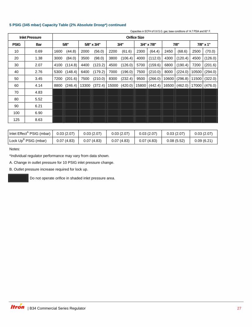
5 PSIG (345 mbar) Capacity Table (2% Absolute Droop*) continued
Capacities in SCFH of 0.6 S.G. gas; base conditions of 14.7 PSIA and 60° F.
Inlet Pressure Orifice Size
PSIG Bar 5/8" 5/8" x 3/4" 3/4" 3/4" x 7/8" 7/8" 7/8" x 1"
10 0.69 1600 (44.8) 2000 (56.0) 2200 (61.6) 2300 (64.4) 2450 (68.6) 2500 (70.0)
20 1.38 3000 (84.0) 3500 (98.0) 3800 (106.4) 4000 (112.0) 4300 (120.4) 4500 (126.0)
30 2.07 4100 (114.8) 4400 (123.2) 4500 (126.0) 5700 (159.6) 6800 (190.4) 7200 (201.6)
40 2.76 5300 (148.4) 6400 (179.2) 7000 (196.0) 7500 (210.0) 8000 (224.0) 10500 (294.0)
50 3.45 7200 (201.6) 7500 (210.0) 8300 (232.4) 9500 (266.0) 10600 (296.8) 11500 (322.0)
60 4.14 8800 (246.4) 13300 (372.4) 15000 (420.0) 15800 (442.4) 16500 (462.0) 17000 (476.0)
70 4.83
80 5.52
90 6.21
100 6.90
125 8.63
Inlet EffectA PSIG (mbar) 0.03 (2.07) 0.03 (2.07) 0.03 (2.07) 0.03 (2.07) 0.03 (2.07) 0.03 (2.07)
Lock UpB PSIG (mbar) 0.07 (4.83) 0.07 (4.83) 0.07 (4.83) 0.07 (4.83) 0.08 (5.52) 0.09 (6.21)
Notes:
*Individual regulator performance may vary from data shown.
A. Change in outlet pressure for 10 PSIG inlet pressure change.
B. Outlet pressure increase required for lock up.
Do not operate orifice in shaded inlet pressure area.
28 B34 Commercial Series Regulator |
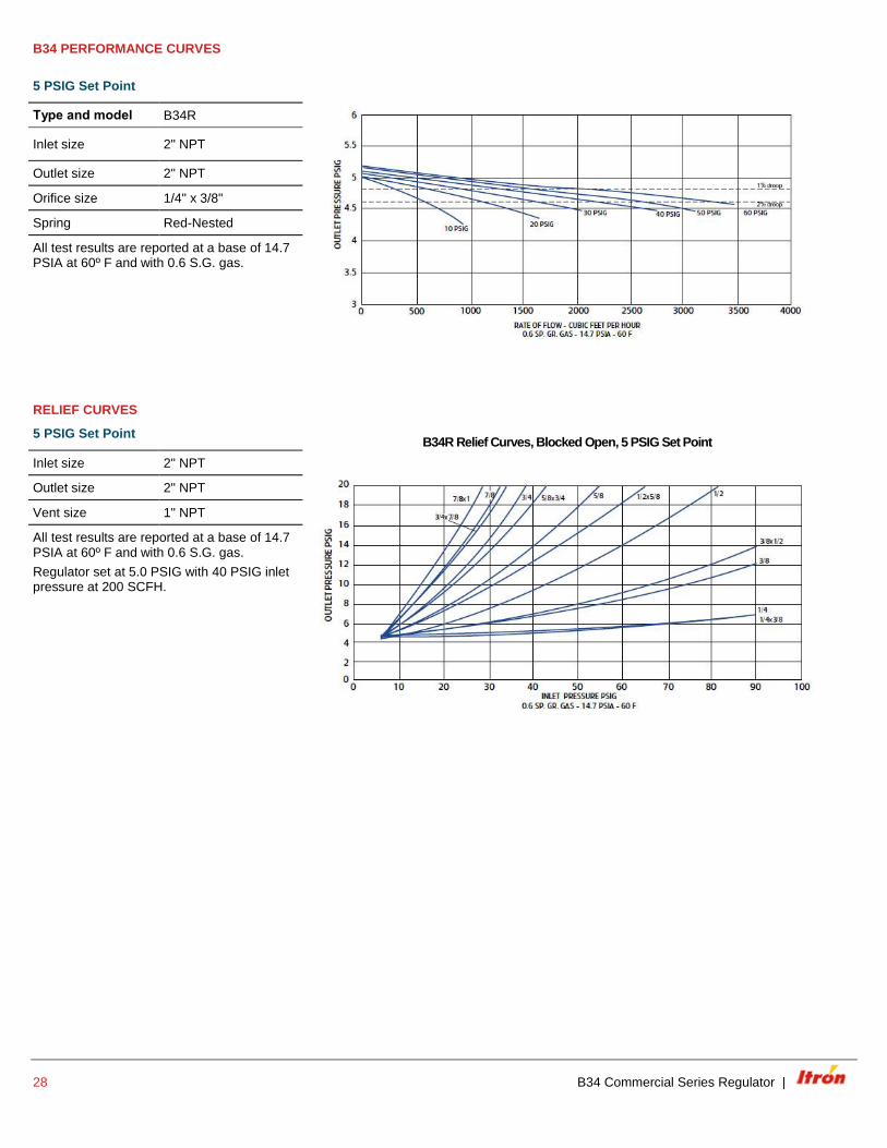
B34 PERFORMANCE CURVES
5 PSIG Set Point
Type and model B34R
Inlet size 2" NPT
Outlet size 2" NPT
Orifice size 1/4" x 3/8"
Spring Red-Nested
All test results are reported at a base of 14.7 PSIA at 60º F and with 0.6 S.G. gas.
RELIEF CURVES
5 PSIG Set Point
B34R Relief Curves, Blocked Open, 5 PSIG Set Point
Inlet size 2" NPT
Outlet size 2" NPT
Vent size 1" NPT
All test results are reported at a base of 14.7 PSIA at 60º F and with 0.6 S.G. gas.
Regulator set at 5.0 PSIG with 40 PSIG inlet pressure at 200 SCFH.
| B34 Commercial Series Regulator 29
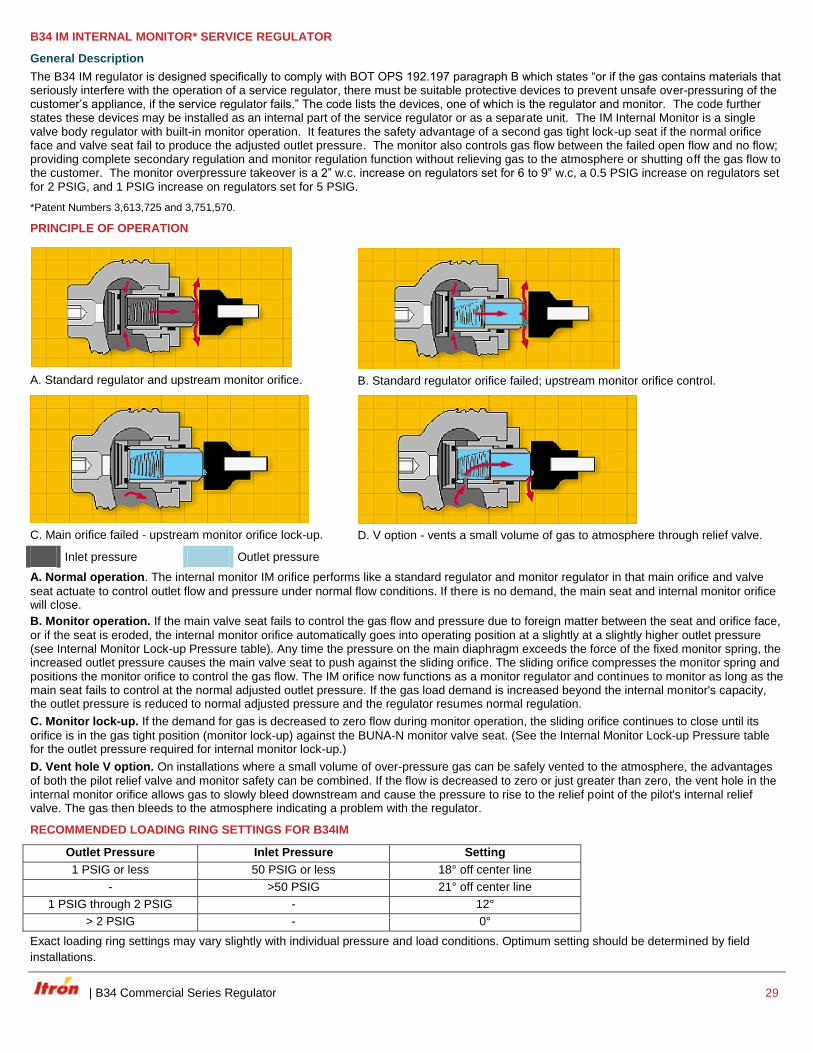
B34 IM INTERNAL MONITOR* SERVICE REGULATOR
General Description
The B34 IM regulator is designed specifically to comply with BOT OPS 192.197 paragraph B which states “or if the gas contains materials that seriously interfere with the operation of a service regulator, there must be suitable protective devices to prevent unsafe over-pressuring of the customer’s appliance, if the service regulator fails.” The code lists the devices, one of which is the regulator and monitor. The code further states these devices may be installed as an internal part of the service regulator or as a separate unit. The IM Internal Monitor is a single valve body regulator with built-in monitor operation. It features the safety advantage of a second gas tight lock-up seat if the normal orifice face and valve seat fail to produce the adjusted outlet pressure. The monitor also controls gas flow between the failed open flow and no flow; providing complete secondary regulation and monitor regulation function without relieving gas to the atmosphere or shutting off the gas flow to the customer. The monitor overpressure takeover is a 2” w.c. increase on regulators set for 6 to 9” w.c, a 0.5 PSIG increase on regulators set for 2 PSIG, and 1 PSIG increase on regulators set for 5 PSIG.
*Patent Numbers 3,613,725 and 3,751,570.
PRINCIPLE OF OPERATION
A. Standard regulator and upstream monitor orifice.
B. Standard regulator orifice failed; upstream monitor orifice control.
C. Main orifice failed - upstream monitor orifice lock-up.
D. V option - vents a small volume of gas to atmosphere through relief valve.
Inlet pressure Outlet pressure
A. Normal operation. The internal monitor IM orifice performs like a standard regulator and monitor regulator in that main orifice and valve
seat actuate to control outlet flow and pressure under normal flow conditions. If there is no demand, the main seat and internal monitor orifice will close.
B. Monitor operation. If the main valve seat fails to control the gas flow and pressure due to foreign matter between the seat and orifice face,
or if the seat is eroded, the internal monitor orifice automatically goes into operating position at a slightly at a slightly higher outlet pressure (see Internal Monitor Lock-up Pressure table). Any time the pressure on the main diaphragm exceeds the force of the fixed monitor spring, the increased outlet pressure causes the main valve seat to push against the sliding orifice. The sliding orifice compresses the monitor spring and positions the monitor orifice to control the gas flow. The IM orifice now functions as a monitor regulator and continues to monitor as long as the main seat fails to control at the normal adjusted outlet pressure. If the gas load demand is increased beyond the internal monitor's capacity, the outlet pressure is reduced to normal adjusted pressure and the regulator resumes normal regulation.
C. Monitor lock-up. If the demand for gas is decreased to zero flow during monitor operation, the sliding orifice continues to close until its
orifice is in the gas tight position (monitor lock-up) against the BUNA-N monitor valve seat. (See the Internal Monitor Lock-up Pressure table for the outlet pressure required for internal monitor lock-up.)
D. Vent hole V option. On installations where a small volume of over-pressure gas can be safely vented to the atmosphere, the advantages
of both the pilot relief valve and monitor safety can be combined. If the flow is decreased to zero or just greater than zero, the vent hole in the internal monitor orifice allows gas to slowly bleed downstream and cause the pressure to rise to the relief point of the pilot's internal relief valve. The gas then bleeds to the atmosphere indicating a problem with the regulator.
RECOMMENDED LOADING RING SETTINGS FOR B34IM
Outlet Pressure Inlet Pressure Setting
1 PSIG or less 50 PSIG or less 18° off center line
- >50 PSIG 21° off center line
1 PSIG through 2 PSIG - 12°
> 2 PSIG - 0°
Exact loading ring settings may vary slightly with individual pressure and load conditions. Optimum setting should be determined by field
installations.
30 B34 Commercial Series Regulator |
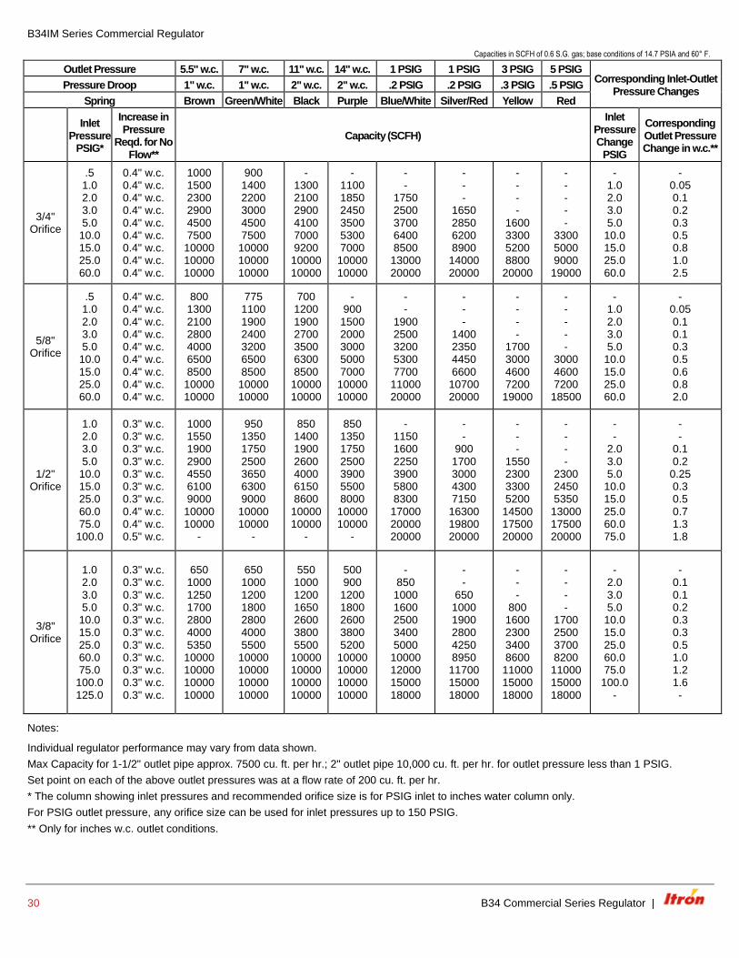
B34IM Series Commercial Regulator
Capacities in SCFH of 0.6 S.G. gas; base conditions of 14.7 PSIA and 60° F.
Outlet Pressure 5.5" w.c. 7" w.c. 11" w.c. 14" w.c. 1 PSIG 1 PSIG 3 PSIG 5 PSIG Corresponding Inlet-Outlet
Pressure Changes Pressure Droop 1" w.c. 1" w.c. 2" w.c. 2" w.c. .2 PSIG .2 PSIG .3 PSIG .5 PSIG
Spring Brown Green/White Black Purple Blue/White Silver/Red Yellow Red
Inlet
Pressure PSIG*
Increase in Pressure
Reqd. for No Flow**
Capacity (SCFH)
Inlet Pressure Change
PSIG
Corresponding Outlet Pressure Change in w.c.**
3/4" Orifice
.5 1.0 2.0 3.0 5.0
10.0 15.0 25.0 60.0
0.4" w.c. 0.4" w.c. 0.4" w.c. 0.4" w.c. 0.4" w.c. 0.4" w.c. 0.4" w.c. 0.4" w.c. 0.4" w.c.
1000 1500 2300 2900 4500 7500
10000 10000 10000
900 1400 2200 3000 4500 7500
10000 10000 10000
- 1300 2100 2900 4100 7000 9200
10000 10000
- 1100 1850 2450 3500 5300 7000
10000 10000
- -
1750 2500 3700 6400 8500
13000 20000
- - -
1650 2850 6200 8900
14000 20000
- - - -
1600 3300 5200 8800
20000
- - - - -
3300 5000 9000
19000
- 1.0 2.0 3.0 5.0
10.0 15.0 25.0 60.0
- 0.05 0.1 0.2 0.3 0.5 0.8 1.0 2.5
5/8" Orifice
.5 1.0 2.0 3.0 5.0
10.0 15.0 25.0 60.0
0.4" w.c. 0.4" w.c. 0.4" w.c. 0.4" w.c. 0.4" w.c. 0.4" w.c. 0.4" w.c. 0.4" w.c. 0.4" w.c.
800 1300 2100 2800 4000 6500 8500
10000 10000
775 1100 1900 2400 3200 6500 8500
10000 10000
700 1200 1900 2700 3500 6300 8500
10000 10000
- 900
1500 2000 3000 5000 7000
10000 10000
- -
1900 2500 3200 5300 7700
11000 20000
- - -
1400 2350 4450 6600
10700 20000
- - - -
1700 3000 4600 7200
19000
- - - - -
3000 4600 7200
18500
- 1.0 2.0 3.0 5.0
10.0 15.0 25.0 60.0
- 0.05 0.1 0.1 0.3 0.5 0.6 0.8 2.0
1/2" Orifice
1.0 2.0 3.0 5.0
10.0 15.0 25.0 60.0 75.0
100.0
0.3" w.c. 0.3" w.c. 0.3" w.c. 0.3" w.c. 0.3" w.c. 0.3" w.c. 0.3" w.c. 0.4" w.c. 0.4" w.c. 0.5" w.c.
1000 1550 1900 2900 4550 6100 9000
10000 10000
-
950 1350 1750 2500 3650 6300 9000
10000 10000
-
850 1400 1900 2600 4000 6150 8600
10000 10000
-
850 1350 1750 2500 3900 5500 8000
10000 10000
-
- 1150 1600 2250 3900 5800 8300
17000 20000 20000
- -
900 1700 3000 4300 7150
16300 19800 20000
- - -
1550 2300 3300 5200
14500 17500 20000
- - - -
2300 2450 5350
13000 17500 20000
- -
2.0 3.0 5.0
10.0 15.0 25.0 60.0 75.0
- -
0.1 0.2
0.25 0.3 0.5 0.7 1.3 1.8
3/8" Orifice
1.0 2.0 3.0 5.0
10.0 15.0 25.0 60.0 75.0
100.0 125.0
0.3" w.c. 0.3" w.c. 0.3" w.c. 0.3" w.c. 0.3" w.c. 0.3" w.c. 0.3" w.c. 0.3" w.c. 0.3" w.c. 0.3" w.c. 0.3" w.c.
650 1000 1250 1700 2800 4000 5350
10000 10000 10000 10000
650 1000 1200 1800 2800 4000 5500
10000 10000 10000 10000
550 1000 1200 1650 2600 3800 5500
10000 10000 10000 10000
500 900
1200 1800 2600 3800 5200
10000 10000 10000 10000
- 850
1000 1600 2500 3400 5000
10000 12000 15000 18000
- -
650 1000 1900 2800 4250 8950
11700 15000 18000
- - -
800 1600 2300 3400 8600
11000 15000 18000
- - - -
1700 2500 3700 8200
11000 15000 18000
- 2.0 3.0 5.0
10.0 15.0 25.0 60.0 75.0
100.0 -
- 0.1 0.1 0.2 0.3 0.3 0.5 1.0 1.2 1.6 -
Notes:
Individual regulator performance may vary from data shown.
Max Capacity for 1-1/2" outlet pipe approx. 7500 cu. ft. per hr.; 2" outlet pipe 10,000 cu. ft. per hr. for outlet pressure less than 1 PSIG.
Set point on each of the above outlet pressures was at a flow rate of 200 cu. ft. per hr.
* The column showing inlet pressures and recommended orifice size is for PSIG inlet to inches water column only.
For PSIG outlet pressure, any orifice size can be used for inlet pressures up to 150 PSIG.
** Only for inches w.c. outlet conditions.
| B34 Commercial Series Regulator 31
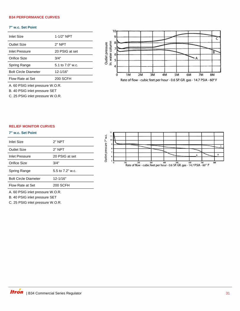
B34 PERFORMANCE CURVES
7" w.c. Set Point
Inlet Size 1-1/2" NPT
Outlet Size 2" NPT
Inlet Pressure 20 PSIG at set
Orifice Size 3/4"
Spring Range 5.1 to 7.0" w.c.
Bolt Circle Diameter 12-1/16"
Flow Rate at Set 200 SCFH
A. 60 PSIG inlet pressure W.O.R.
B. 40 PSIG inlet pressure SET
C. 25 PSIG inlet pressure W.O.R.
RELIEF MONITOR CURVES
7" w.c. Set Point
Inlet Size 2" NPT
Outlet Size 2" NPT
Inlet Pressure 20 PSIG at set
Orifice Size 3/4"
Spring Range 5.5 to 7.2" w.c.
Bolt Circle Diameter 12-1/16"
Flow Rate at Set 200 SCFH
A. 60 PSIG inlet pressure W.O.R.
B. 40 PSIG inlet pressure SET
C. 25 PSIG inlet pressure W.O.R.
32 B34 Commercial Series Regulator |
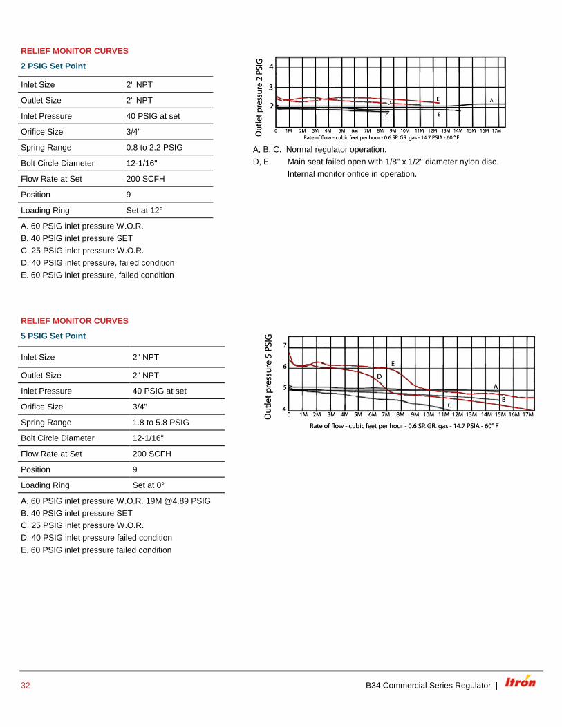
RELIEF MONITOR CURVES
2 PSIG Set Point
A, B, C. Normal regulator operation.
D, E. Main seat failed open with 1/8" x 1/2" diameter nylon disc.
Internal monitor orifice in operation.
Inlet Size 2" NPT
Outlet Size 2" NPT
Inlet Pressure 40 PSIG at set
Orifice Size 3/4"
Spring Range 0.8 to 2.2 PSIG
Bolt Circle Diameter 12-1/16"
Flow Rate at Set 200 SCFH
Position 9
Loading Ring Set at 12°
A. 60 PSIG inlet pressure W.O.R.
B. 40 PSIG inlet pressure SET
C. 25 PSIG inlet pressure W.O.R.
D. 40 PSIG inlet pressure, failed condition
E. 60 PSIG inlet pressure, failed condition
RELIEF MONITOR CURVES
5 PSIG Set Point
Inlet Size 2" NPT
Outlet Size 2" NPT
Inlet Pressure 40 PSIG at set
Orifice Size 3/4"
Spring Range 1.8 to 5.8 PSIG
Bolt Circle Diameter 12-1/16"
Flow Rate at Set 200 SCFH
Position 9
Loading Ring Set at 0°
A. 60 PSIG inlet pressure W.O.R. 19M @4.89 PSIG
B. 40 PSIG inlet pressure SET
C. 25 PSIG inlet pressure W.O.R.
D. 40 PSIG inlet pressure failed condition
E. 60 PSIG inlet pressure failed condition
| B34 Commercial Series Regulator 33
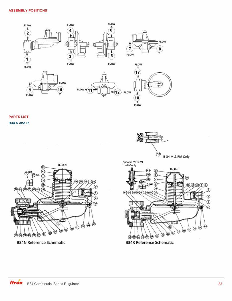
ASSEMBLY POSITIONS
PARTS LIST
B34 N and R
34 B34 Commercial Series Regulator |
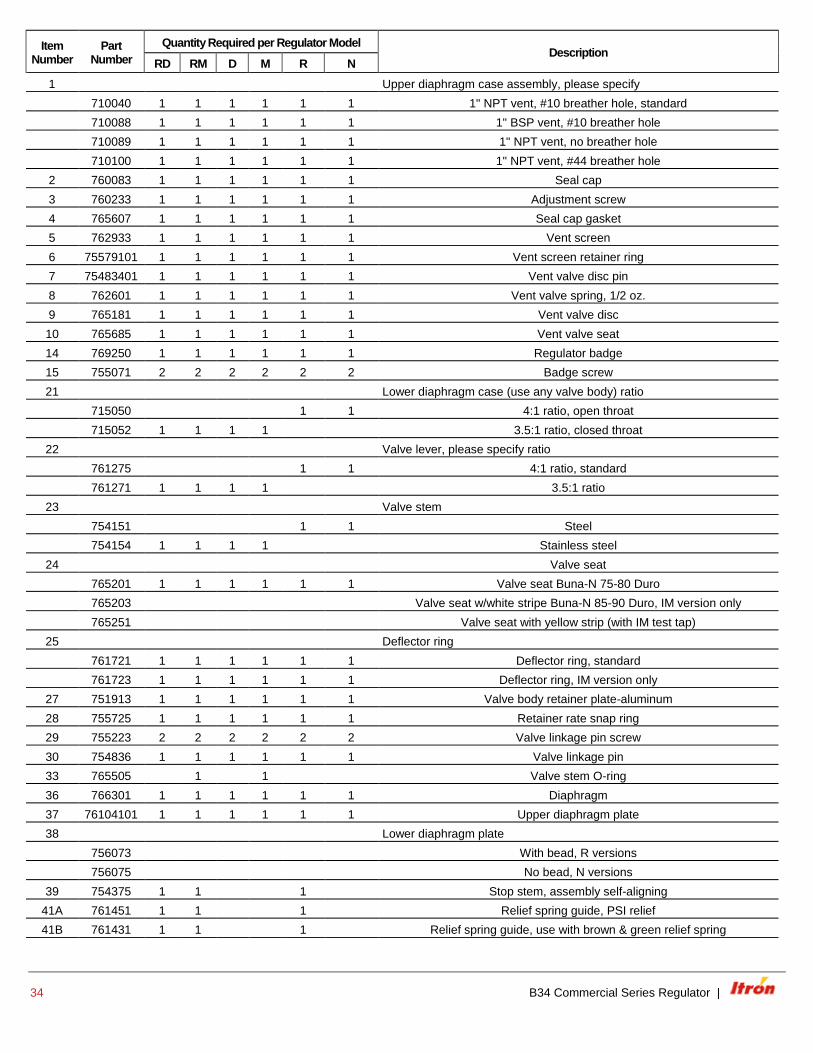
Item Number
Part Number
Quantity Required per Regulator Model Description
RD RM D M R N
1 Upper diaphragm case assembly, please specify
710040 1 1 1 1 1 1 1" NPT vent, #10 breather hole, standard
710088 1 1 1 1 1 1 1" BSP vent, #10 breather hole
710089 1 1 1 1 1 1 1" NPT vent, no breather hole
710100 1 1 1 1 1 1 1" NPT vent, #44 breather hole
2 760083 1 1 1 1 1 1 Seal cap
3 760233 1 1 1 1 1 1 Adjustment screw
4 765607 1 1 1 1 1 1 Seal cap gasket
5 762933 1 1 1 1 1 1 Vent screen
6 75579101 1 1 1 1 1 1 Vent screen retainer ring
7 75483401 1 1 1 1 1 1 Vent valve disc pin
8 762601 1 1 1 1 1 1 Vent valve spring, 1/2 oz.
9 765181 1 1 1 1 1 1 Vent valve disc
10 765685 1 1 1 1 1 1 Vent valve seat
14 769250 1 1 1 1 1 1 Regulator badge
15 755071 2 2 2 2 2 2 Badge screw
21 Lower diaphragm case (use any valve body) ratio
715050 1 1 4:1 ratio, open throat
715052 1 1 1 1 3.5:1 ratio, closed throat
22 Valve lever, please specify ratio
761275 1 1 4:1 ratio, standard
761271 1 1 1 1 3.5:1 ratio
23 Valve stem
754151 1 1 Steel
754154 1 1 1 1 Stainless steel
24 Valve seat
765201 1 1 1 1 1 1 Valve seat Buna-N 75-80 Duro
765203 Valve seat w/white stripe Buna-N 85-90 Duro, IM version only
765251 Valve seat with yellow strip (with IM test tap)
25 Deflector ring
761721 1 1 1 1 1 1 Deflector ring, standard
761723 1 1 1 1 1 1 Deflector ring, IM version only
27 751913 1 1 1 1 1 1 Valve body retainer plate-aluminum
28 755725 1 1 1 1 1 1 Retainer rate snap ring
29 755223 2 2 2 2 2 2 Valve linkage pin screw
30 754836 1 1 1 1 1 1 Valve linkage pin
33 765505 1 1 Valve stem O-ring
36 766301 1 1 1 1 1 1 Diaphragm
37 76104101 1 1 1 1 1 1 Upper diaphragm plate
38 Lower diaphragm plate
756073 With bead, R versions
756075 No bead, N versions
39 754375 1 1 1 Stop stem, assembly self-aligning
41A 761451 1 1 1 Relief spring guide, PSI relief
41B 761431 1 1 1 Relief spring guide, use with brown & green relief spring
| B34 Commercial Series Regulator 35
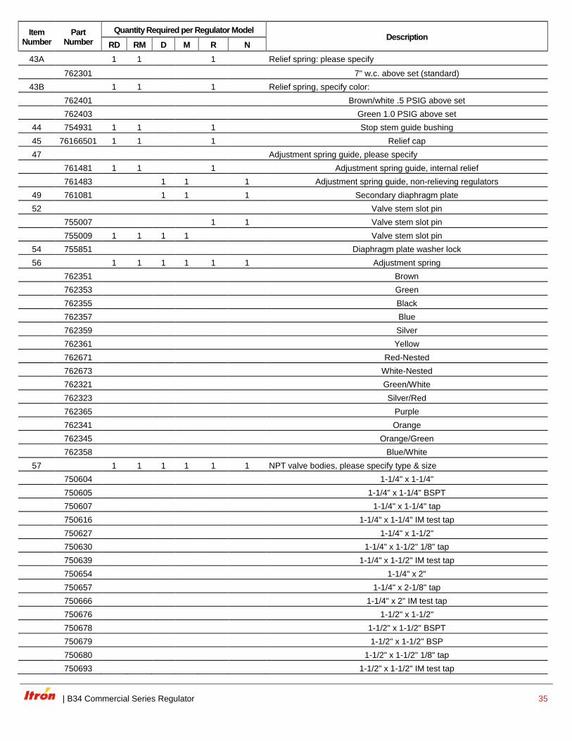
Item Number
Part Number
Quantity Required per Regulator Model Description
RD RM D M R N
43A 1 1 1 Relief spring: please specify
762301 7" w.c. above set (standard)
43B 1 1 1 Relief spring, specify color:
762401 Brown/white .5 PSIG above set
762403 Green 1.0 PSIG above set
44 754931 1 1 1 Stop stem guide bushing
45 76166501 1 1 1 Relief cap
47 Adjustment spring guide, please specify
761481 1 1 1 Adjustment spring guide, internal relief
761483 1 1 1 Adjustment spring guide, non-relieving regulators
49 761081 1 1 1 Secondary diaphragm plate
52 Valve stem slot pin
755007 1 1 Valve stem slot pin
755009 1 1 1 1 Valve stem slot pin
54 755851 Diaphragm plate washer lock
56 1 1 1 1 1 1 Adjustment spring
762351 Brown
762353 Green
762355 Black
762357 Blue
762359 Silver
762361 Yellow
762671 Red-Nested
762673 White-Nested
762321 Green/White
762323 Silver/Red
762365 Purple
762341 Orange
762345 Orange/Green
762358 Blue/White
57 1 1 1 1 1 1 NPT valve bodies, please specify type & size
750604 1-1/4" x 1-1/4"
750605 1-1/4" x 1-1/4" BSPT
750607 1-1/4" x 1-1/4" tap
750616 1-1/4" x 1-1/4" IM test tap
750627 1-1/4" x 1-1/2"
750630 1-1/4" x 1-1/2" 1/8" tap
750639 1-1/4" x 1-1/2" IM test tap
750654 1-1/4" x 2"
750657 1-1/4" x 2-1/8" tap
750666 1-1/4" x 2" IM test tap
750676 1-1/2" x 1-1/2"
750678 1-1/2" x 1-1/2" BSPT
750679 1-1/2" x 1-1/2" BSP
750680 1-1/2" x 1-1/2" 1/8" tap
750693 1-1/2" x 1-1/2" IM test tap
36 B34 Commercial Series Regulator |
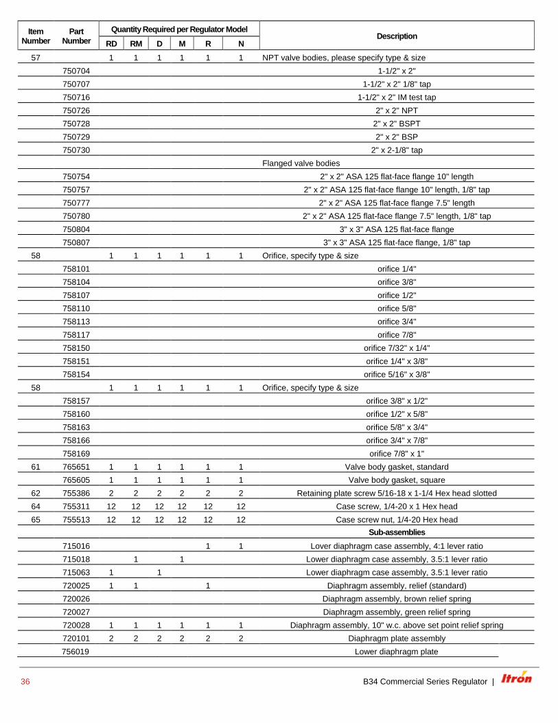
Item Number
Part Number
Quantity Required per Regulator Model Description
RD RM D M R N
57 1 1 1 1 1 1 NPT valve bodies, please specify type & size
750704 1-1/2" x 2"
750707 1-1/2" x 2" 1/8" tap
750716 1-1/2" x 2" IM test tap
750726 2" x 2" NPT
750728 2" x 2" BSPT
750729 2" x 2" BSP
750730 2" x 2-1/8" tap
Flanged valve bodies
750754 2" x 2" ASA 125 flat-face flange 10" length
750757 2" x 2" ASA 125 flat-face flange 10" length, 1/8" tap
750777 2" x 2" ASA 125 flat-face flange 7.5" length
750780 2" x 2" ASA 125 flat-face flange 7.5" length, 1/8" tap
750804 3" x 3" ASA 125 flat-face flange
750807 3" x 3" ASA 125 flat-face flange, 1/8" tap
58 1 1 1 1 1 1 Orifice, specify type & size
758101 orifice 1/4"
758104 orifice 3/8"
758107 orifice 1/2"
758110 orifice 5/8"
758113 orifice 3/4"
758117 orifice 7/8"
758150 orifice 7/32" x 1/4"
758151 orifice 1/4" x 3/8"
758154 orifice 5/16" x 3/8"
58 1 1 1 1 1 1 Orifice, specify type & size
758157 orifice 3/8" x 1/2"
758160 orifice 1/2" x 5/8"
758163 orifice 5/8" x 3/4"
758166 orifice 3/4" x 7/8"
758169 orifice 7/8" x 1"
61 765651 1 1 1 1 1 1 Valve body gasket, standard
765605 1 1 1 1 1 1 Valve body gasket, square
62 755386 2 2 2 2 2 2 Retaining plate screw 5/16-18 x 1-1/4 Hex head slotted
64 755311 12 12 12 12 12 12 Case screw, 1/4-20 x 1 Hex head
65 755513 12 12 12 12 12 12 Case screw nut, 1/4-20 Hex head
Sub-assemblies
715016 1 1 Lover diaphragm case assembly, 4:1 lever ratio
715018 1 1 Lower diaphragm case assembly, 3.5:1 lever ratio
715063 1 1 Lower diaphragm case assembly, 3.5:1 lever ratio
720025 1 1 1 Diaphragm assembly, relief (standard)
720026 Diaphragm assembly, brown relief spring
720027 Diaphragm assembly, green relief spring
720028 1 1 1 1 1 1 Diaphragm assembly, 10" w.c. above set point relief spring
720101 2 2 2 2 2 2 Diaphragm plate assembly
756019 Lower diaphragm plate
| B34 Commercial Series Regulator 37
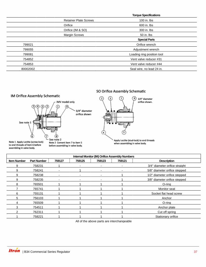
Torque Specifications
Retainer Plate Screws 100 in. lbs
Orifice 600 in. lbs
Orifice (IM & SO) 300 in. lbs
Margin Screws 50 in. lbs
Special Parts
799021 Orifice wrench
799055 Adjustment wrench
799081 Loading ring position tool
754852 Vent valve reducer #31
754853 Vent valve reducer #44
80002002 Seal wire, no lead 24 in.
Internal Monitor (IM) Orifice Assembly Numbers
Item Number Part Number 759127 759125 759123 759121 Description
9 758231 1 - - - 3/4" diameter orifice straight
9 758241 - 1 - - 5/8" diameter orifice stepped
9 758238 - - - 1 1/2" diameter orifice stepped
9 758235 - - - 1 3/8" diameter orifice stepped
8 765501 1 1 1 1 O-ring
7 765741 1 1 1 1 Monitor seat
6 755131 1 1 1 1 Socket flat head screw
5 756103 1 1 1 1 Anchor
4 765509 1 1 1 1 O-ring
3 754511 1 1 1 1 Anchor plate
2 762311 1 1 1 1 Cut off spring
1 758221 1 1 1 1 Stationary orifice
All of the above parts are interchangeable
38 B34 Commercial Series Regulator |
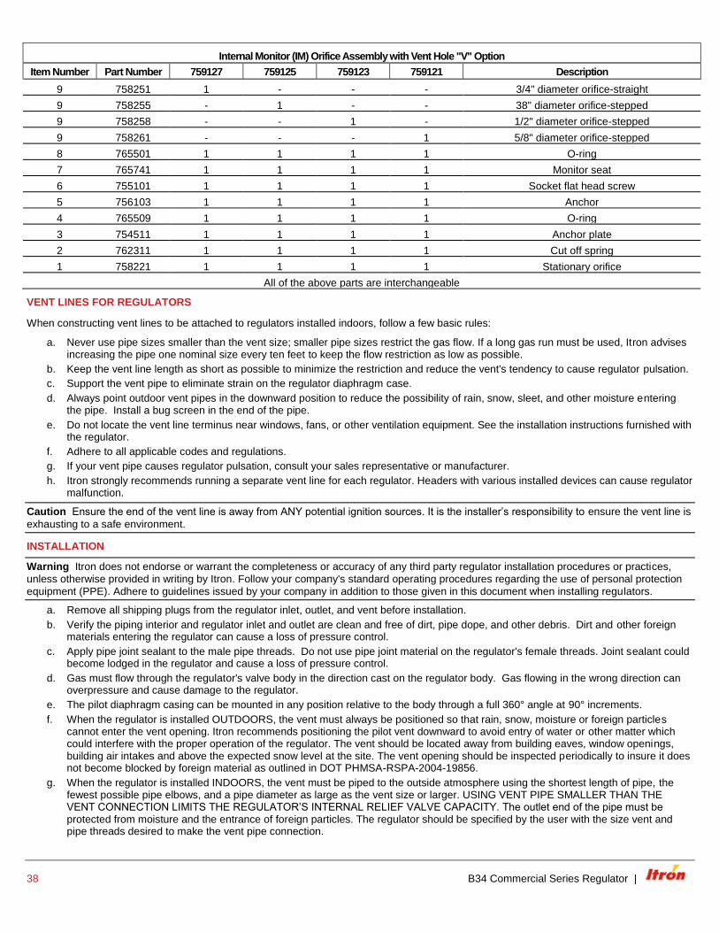
Internal Monitor (IM) Orifice Assembly with Vent Hole "V" Option
Item Number Part Number 759127 759125 759123 759121 Description
9 758251 1 - - - 3/4" diameter orifice-straight
9 758255 - 1 - - 38" diameter orifice-stepped
9 758258 - - 1 - 1/2" diameter orifice-stepped
9 758261 - - - 1 5/8" diameter orifice-stepped
8 765501 1 1 1 1 O-ring
7 765741 1 1 1 1 Monitor seat
6 755101 1 1 1 1 Socket flat head screw
5 756103 1 1 1 1 Anchor
4 765509 1 1 1 1 O-ring
3 754511 1 1 1 1 Anchor plate
2 762311 1 1 1 1 Cut off spring
1 758221 1 1 1 1 Stationary orifice
All of the above parts are interchangeable
VENT LINES FOR REGULATORS
When constructing vent lines to be attached to regulators installed indoors, follow a few basic rules:
a. Never use pipe sizes smaller than the vent size; smaller pipe sizes restrict the gas flow. If a long gas run must be used, Itron advises increasing the pipe one nominal size every ten feet to keep the flow restriction as low as possible.
b. Keep the vent line length as short as possible to minimize the restriction and reduce the vent's tendency to cause regulator pulsation.
c. Support the vent pipe to eliminate strain on the regulator diaphragm case.
d. Always point outdoor vent pipes in the downward position to reduce the possibility of rain, snow, sleet, and other moisture entering the pipe. Install a bug screen in the end of the pipe.
e. Do not locate the vent line terminus near windows, fans, or other ventilation equipment. See the installation instructions furnished with the regulator.
f. Adhere to all applicable codes and regulations.
g. If your vent pipe causes regulator pulsation, consult your sales representative or manufacturer.
h. Itron strongly recommends running a separate vent line for each regulator. Headers with various installed devices can cause regulator malfunction.
Caution Ensure the end of the vent line is away from ANY potential ignition sources. It is the installer’s responsibility to ensure the vent line is
exhausting to a safe environment.
INSTALLATION
Warning Itron does not endorse or warrant the completeness or accuracy of any third party regulator installation procedures or practices,
unless otherwise provided in writing by Itron. Follow your company's standard operating procedures regarding the use of personal protection
equipment (PPE). Adhere to guidelines issued by your company in addition to those given in this document when installing regulators.
a. Remove all shipping plugs from the regulator inlet, outlet, and vent before installation.
b. Verify the piping interior and regulator inlet and outlet are clean and free of dirt, pipe dope, and other debris. Dirt and other foreign materials entering the regulator can cause a loss of pressure control.
c. Apply pipe joint sealant to the male pipe threads. Do not use pipe joint material on the regulator's female threads. Joint sealant could become lodged in the regulator and cause a loss of pressure control.
d. Gas must flow through the regulator's valve body in the direction cast on the regulator body. Gas flowing in the wrong direction can overpressure and cause damage to the regulator.
e. The pilot diaphragm casing can be mounted in any position relative to the body through a full 360° angle at 90° increments.
f. When the regulator is installed OUTDOORS, the vent must always be positioned so that rain, snow, moisture or foreign particles cannot enter the vent opening. Itron recommends positioning the pilot vent downward to avoid entry of water or other matter which could interfere with the proper operation of the regulator. The vent should be located away from building eaves, window openings, building air intakes and above the expected snow level at the site. The vent opening should be inspected periodically to insure it does not become blocked by foreign material as outlined in DOT PHMSA-RSPA-2004-19856.
g. When the regulator is installed INDOORS, the vent must be piped to the outside atmosphere using the shortest length of pipe, the fewest possible pipe elbows, and a pipe diameter as large as the vent size or larger. USING VENT PIPE SMALLER THAN THE VENT CONNECTION LIMITS THE REGULATOR’S INTERNAL RELIEF VALVE CAPACITY. The outlet end of the pipe must be protected from moisture and the entrance of foreign particles. The regulator should be specified by the user with the size vent and pipe threads desired to make the vent pipe connection.
| B34 Commercial Series Regulator 39
START-UP PROCEDURE
a. Mount a pressure gauge downstream of the regulator to monitor the downstream pressure.
b. With the downstream pressure valve closed, slowly open the inlet valve. The outlet pressure should rise to slightly more than the set-point. Verify there are no leaks and all connections are tight.
c. The regulator was pre-set at the factory to match order specifications. If necessary, adjust the outlet pressure by removing the seal cap on the top of the pilot spring housing and adjusting the ferrule or screw inside the pilot spring housing using a large flat-head screwdriver. With a small amount of gas flowing through the regulator, rotate the pilot ferrule clockwise to raise the outlet pressure or counter-clockwise to lower the outlet pressure.
d. Replace the seal cap and check for leaks after the desired outlet pressure is achieved.
The regulator is ready for operation.
SAFETY WARNING
This product, as of the date of manufacture, is designed and tested to conform to all governmental and industry safety standards as they may apply to the manufacturer. The purchaser/user of this product must comply with all fire control, building codes, and other safety regulations governing the application, installation, operation, and general use of this regulator to avoid leaking gas hazards resulting from improper installation, startup or use of this product.
Itron strongly recommends installation by a qualified professional and periodic inspection of pressure regulators (inspections may be required by local applicable codes or regulations).
Inspections should include checking for gas quality, cycle numbers, external environmental changes, and operating conditions that impact wear on the regulator's moving parts. To ensure safe and efficient operation of this product, replace worn or damaged parts found during inspection.
LIMITED WARRANTY
Itron, Inc. 970 Highway 127 North, Owenton, Kentucky 40359-9302, warrants this gas product against defects in materials and workmanship for the earlier of one (1) year from the date the product is shipped by Itron or a period of one year from the date the product is installed by Itron at the original purchaser’s site. During such one-year period, provided that the original purchaser continues to own the product, Itron will, at its sole option, repair any defects, replace the product or repay the purchase price.
» This warranty will be void if the purchaser fails to observe the procedures for installation, operation or service of the product as set forth in the Operating Manual and Specifications for the product or if the defect is caused by tampering, physical abuse or misuse of the product.
» ITRON SPECIFICALLY DISCLAIMS ALL IMPLIED WARRANTIES INCLUDING THOSE OF MERCHANTABILITY OR OF FITNESS FOR A PARTICULAR PURPOSE. UNDER NO CIRCUMSTANCES WILL ITRON BE LIABLE FOR INCIDENTAL OR CONSEQUENTIAL DAMAGES OF ANY KIND WHATSOEVER.
» Itron’s liability for any claim of any kind, including negligence and breach of warranty for the sale and use of any product covered by or furnished, shall in no case exceed the price allocable to the product or part thereof which gives rise to the claim.
» In the event of a malfunction of the product, consult your Itron Service Representative or Itron Inc., 970 Highway 127 North, Owenton, Kentucky 40359-9302. See Itron Terms and Conditions of Sale for the full and complete terms of the Limited Warranty.
ORDERING INFORMATION
Specify:
1. Inlet and outlet connection size and type
2. Model number
3. Outlet pressure desired
4. Pilot needed
5. Inlet pressure range
6. Type of gas and maximum capacity required
7. Assembly position number (see chart above)
8. Special requirements such as tagging, 1/8" pipe plug tap, seal wire, etc.
While Itron strives to make the content of its marketing materials as timely and accurate as possible, Itron makes no claims, promises, or guarantees about the accuracy, completeness, or adequacy of, and expressly disclaims liability for errors and omissions in, such materials. No warranty of any kind, implied, expressed, or statutory, including but not limited to the warranties of non-infringement of third party rights, title, merchantability, and fitness for a particular purpose, is given with respect to the content of these marketing materials. © Copyright 2012, Itron. All rights reserved. 101062SP-04 01/12
Itron is the world’s leading provider of smart metering, data collection and utility software systems, with over 8,000 utilities worldwide relying on our solutions to responsibly and efficiently manage the delivery and use of energy and water. To realize your smarter energy and water future, start here: www.itron.com
ITRON GAS
970 Highway 127 North Owenton, Kentucky 40359 USA
Phone: 1.800.490.0657 Fax: 1.502.484.6223
CORPORATE HEADQUARTERS
2111 N Molter Road Liberty Lake, WA 99019 USA
Phone: 1.800.635.5461 Fax: 1.509.891.3355