b5: footways - city of · pdf file · 2016-12-08b5. footways version 2: 22.3.2013...
TRANSCRIPT
B5: Footways City of Sydney Town Hall House 456 Kent Street Sydney NSW 2000
Construction
Sydney Streets Technical Specifications
B5. Footways
Version 2: 22.3.2013 Page i
Table of Contents
5.1 Scope ................................................................................................................................... 1
5.2 Standards and Guidelines .................................................................................................. 1
5.3 Materials .............................................................................................................................. 3 5.3.1 Stone Paver Requirements ............................................................................................. 3 5.3.2 Concrete Unit Paver Requirements ................................................................................. 5 5.3.3 Brick Paver Requirements ............................................................................................... 7 5.3.4 Quality Control Samples for Pavers ................................................................................ 8 5.3.5 Mortar Bed Materials ....................................................................................................... 8 5.3.6 Bedding Sand ................................................................................................................. 8 5.3.7 Asphalt ............................................................................................................................ 9 5.3.8 Concrete ......................................................................................................................... 9 5.3.9 Basecourse Materials ...................................................................................................... 9 5.3.10 Structural Soils ................................................................................................................ 9
5.4 Construction ...................................................................................................................... 10 5.4.1 General ......................................................................................................................... 10 5.4.2 Excavation of Existing Pavers ....................................................................................... 10 5.4.3 Cutting and Preparation of Pavers ................................................................................ 10 5.4.4 Subgrade ...................................................................................................................... 11 5.4.5 Basecourses ................................................................................................................. 11 5.4.6 Method of Laying Stone and Concrete Unit Pavers ....................................................... 12 5.4.7 Method of Laying Brick Pavers ..................................................................................... 12 5.4.8 Laying Arrangements .................................................................................................... 14 5.4.9 Expansion and Contraction Joints ................................................................................ 14 5.4.10 Edge Restraint for Brick Paving .................................................................................... 14 5.4.11 Laying of Asphalt Paving ............................................................................................... 14 5.4.12 In-situ Concrete Paving ................................................................................................. 14 5.4.13 Cleaning ....................................................................................................................... 15 5.4.14 Protective Sealant ......................................................................................................... 15
5.5 Vehicular Crossings (Driveways), Kerb Ramps and Stairs ............................................ 15 5.5.1 Removal ........................................................................................................................ 16 5.5.2 Construction ................................................................................................................. 16 5.5.2.1 Vehicular Crossings (Driveways) ................................................................................... 16 5.5.2.2 Kerb Ramps .................................................................................................................. 16 5.5.2.3 Reinforced Concrete Stairs ........................................................................................... 16 5.5.3 Surface Finish ............................................................................................................... 17
5.6 Tactile Ground Surface Indicators (TGSIs) ...................................................................... 17
5.7 Handrails ............................................................................................................................ 17
5.8 Utility Covers ..................................................................................................................... 17 5.8.1 General ......................................................................................................................... 17 5.8.2 Adjustment and Relocation ........................................................................................... 17 5.8.3 Authority Standards ...................................................................................................... 18
Sydney Streets Technical Specifications
B5. Footways
Version 2: 22.3.2013 Page ii
5.8.4 Loadings ....................................................................................................................... 18
5.9 Quality ................................................................................................................................ 19 5.9.1 Load Testing ................................................................................................................. 19 5.9.2 In-situ Slip Resistance Testing of New Surfaces ........................................................... 19 5.9.3 Inspections ................................................................................................................... 20 5.9.3.1 Hold and Witness Points ............................................................................................... 20 5.9.3.2 Tolerances .................................................................................................................... 21
Sydney Streets Technical Specifications
B5. Footways
Version 4: June 2016 Page 1
5.1 Scope
This work section provides for the construction of footway pavements including the supply, quality
and placement of various pavement materials and finishes, to the alignment, dimensions, cross
sections and levels shown on the construction documents or as directed by the City’s
Representative.
5.2 Standards and Guidelines
Unless stated otherwise in the Specification, the approved drawings or elsewhere in the
construction documents, work shall comply with the current and relevant Australian Standards
and/or RMS Standards.
Any variations or ambiguity between Specifications, the approved drawings or other construction
documents and Australian Standards shall be referred to the City’s Representative for decision
before proceeding with the work.
The following table indicates the Australian Standards and/or RMS Standards applicable to this
section. This table is not exhaustive and may not include all standards which may apply to the
work to be undertaken:
AS1141.26 Methods for sampling and testing aggregates: Secondary minerals content
in igneous rocks;
AS/NZS 1428.4.1 Means to assist the orientation of people with vision impairment - Tactile
ground surface indicators;
AS 2150 Hot mix asphalt – A guide to good practice;
AUSPEC 1144 ASPHALT (ROADWAYS)
AS/NZS 4455 Masonry Units and Segmental Pavers;
AS/NZS 4456 Masonry Units and Segmental Pavers – Methods of Test;
AS/NZS 4586 Slip Resistance Classification of New Pedestrian Surface Materials;
AS/NZS 4456.5 Determining Breaking Load of Segmental Paving Units;
AS/NZS 4456.9 Determining Abrasion Resistance;
AS/NZS 4456.10 Determining Resistance to Salt Attack;
AS/NZS 4586 Slip Resistance Classification of New Pedestrian Surface Materials: Wet
Appendix A Pendulum Test Method;
ASTM Standard Specification for Granite Dimension Stone;
C615/C615M-11
CBPI Clay Paving Design and Construction; and
CCMA Concrete Flag Pavements Design and Construction Guide, (MA44).

Sydney Streets Technical Specifications
B5. Footways
Version 4: June 2016 Page 2
Sydney Streets Technical Specifications
B5. Footways
Version 4: June 2016 Page 3
5.3 Materials
5.3.1 Stone Paver Requirements
All stone shall be natural, uniform quality, free of defects (such as vents, cracks, fissures, seams,
porous inclusions, foreign material, loose surface material striations, stains and discoloration)
liable to affect its strength, appearance, durability or proper functioning under the intended
conditions of use.
Stone pavers may be available from suppliers that are currently approved by the City (on request),
or procured from the following quarries only:
Black Hill SA for Austral 'Black' granite;
Fraser Range Norseman WA for Austral ‘Verde’ granite; or
Deer Park VIC for Bluestone.
Other suppliers may be used subject to approval by the City’s Representative. Stone from
alternative suppliers must be selected to match colour, pattern, dimensions and quality of the
specified paver.
Stone paver types:
Austral 'Black' and Austral ‘Verde’ granite pavers with flame exfoliated finish; and
Deer Park Bluestone (Basalt) pavers with sawn finished (generally used for maintenance
purposes only).
The nominated paver thickness for all footways and driveways is 50mm except for distinctive
places such as George Street, Martin Place, Pitt Street Mall which shall be 60mm. The nominated
thickness for infill service lids is 30mm unless specified otherwise. Refer to standard details for
paver sizes and layout pattern.
The supplier shall provide written certification that the supplied granite stone products meet the
international ASTM C615/C615M-11 Standard Specification for Granite Dimension Stone for the
following quality criteria:

Sydney Streets Technical Specifications
B5. Footways
Version 4: June 2016 Page 4
Austral Black:
Property Test Standard Performance Criteria
Compression strength (dry/soaked) ASTM C170/C170M > 185MPa (soaked)
Water absorption ASTM C97/C97M < 0.1% by weight
Bulk density ASTM C97/C97M > 2900kg/m3
Flexural strength (dry and soaked) ASTM C880/C880M > 14MPa (soaked)
Resistance to salt attack AS/NZS 4456.10A Durability Class A
Coefficient of thermal expansion ASTM E831 < 0.000005 mm/mm/0
C
Abrasion Resistance ASTM C1353 > 113 Ha
Slip Resistance on Pedestrian surfaces AS/NZS 4586
Appendix A
P4 ( or P3 upon
Approval)
Dimensional Stability Draft SAA method < 0.1 % (Wet-dry, hot-
cold)
Secondary minerals content
(petrographic) AS 1141.26 < 2%
Austral Verde:
Property Test Standard Performance Criteria
Compression strength (dry/saturated) ASTM C170/C170M > 140MPa (soaked)
Water absorption ASTM C97/C97M < 0.1% by weight
Bulk density ASTM C97/C97M > 2560kg/m3
Flexural strength (dry and saturated) ASTM C880/C880M > 12MPa (soaked)
Resistance to salt attack AS/NZS 4456.10A Durability Class A
Coefficient of thermal expansion ASTM E831 N/A
Abrasion Resistance ASTM C1353 > 54 Ha
Slip Resistance on Pedestrian surfaces AS/NZS 4586
Appendix A
P4 ( or P3 upon
Approval)
Dimensional Stability Draft SAA method < 0.1 % (Wet-dry, hot-
cold)
Secondary minerals content
(petrographic) AS 1141.26 < 2%
Sydney Streets Technical Specifications
B5. Footways
Version 4: June 2016 Page 5
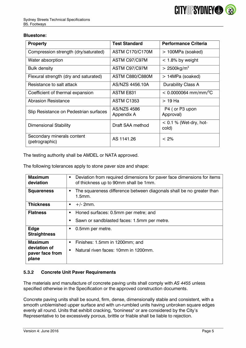
Bluestone:
Property Test Standard Performance Criteria
Compression strength (dry/saturated) ASTM C170/C170M > 100MPa (soaked)
Water absorption ASTM C97/C97M < 1.8% by weight
Bulk density ASTM C97/C97M > 2500kg/m3
Flexural strength (dry and saturated) ASTM C880/C880M > 14MPa (soaked)
Resistance to salt attack AS/NZS 4456.10A Durability Class A
Coefficient of thermal expansion ASTM E831 < 0.0000064 mm/mm/0
C
Abrasion Resistance ASTM C1353 > 19 Ha
Slip Resistance on Pedestrian surfaces AS/NZS 4586
Appendix A
P4 ( or P3 upon
Approval)
Dimensional Stability Draft SAA method < 0.1 % (Wet-dry, hot-
cold)
Secondary minerals content
(petrographic) AS 1141.26 < 2%
The testing authority shall be AMDEL or NATA approved.
The following tolerances apply to stone paver size and shape:
Maximum
deviation
Deviation from required dimensions for paver face dimensions for items
of thickness up to 90mm shall be 1mm.
Squareness The squareness difference between diagonals shall be no greater than
1.5mm.
Thickness +/- 2mm.
Flatness Honed surfaces: 0.5mm per metre; and
Sawn or sandblasted faces: 1.5mm per metre.
Edge
Straightness
0.5mm per metre.
Maximum
deviation of
paver face from
plane
Finishes: 1.5mm in 1200mm; and
Natural riven faces: 10mm in 1200mm.
5.3.2 Concrete Unit Paver Requirements
The materials and manufacture of concrete paving units shall comply with AS 4455 unless
specified otherwise in the Specification or the approved construction documents.
Concrete paving units shall be sound, firm, dense, dimensionally stable and consistent, with a
smooth unblemished upper surface and with un-rumbled units having unbroken square edges
evenly all round. Units that exhibit cracking, "boniness" or are considered by the City’s
Representative to be excessively porous, brittle or friable shall be liable to rejection.
Sydney Streets Technical Specifications
B5. Footways
Version 4: June 2016 Page 6
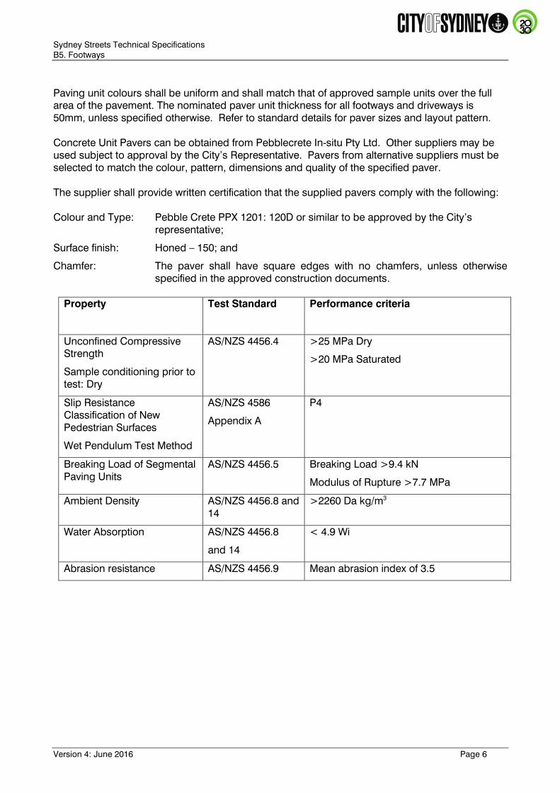
Paving unit colours shall be uniform and shall match that of approved sample units over the full
area of the pavement. The nominated paver unit thickness for all footways and driveways is
50mm, unless specified otherwise. Refer to standard details for paver sizes and layout pattern.
Concrete Unit Pavers can be obtained from Pebblecrete In-situ Pty Ltd. Other suppliers may be
used subject to approval by the City’s Representative. Pavers from alternative suppliers must be
selected to match the colour, pattern, dimensions and quality of the specified paver.
The supplier shall provide written certification that the supplied pavers comply with the following:
Colour and Type: Pebble Crete PPX 1201: 120D or similar to be approved by the City’s
representative;
Surface finish: Honed – 150; and
Chamfer: The paver shall have square edges with no chamfers, unless otherwise
specified in the approved construction documents.
Property Test Standard Performance criteria
Unconfined Compressive
Strength
Sample conditioning prior to
test: Dry
AS/NZS 4456.4 >25 MPa Dry
>20 MPa Saturated
Slip Resistance
Classification of New
Pedestrian Surfaces
Wet Pendulum Test Method
AS/NZS 4586
Appendix A
P4
Breaking Load of Segmental
Paving Units
AS/NZS 4456.5 Breaking Load >9.4 kN
Modulus of Rupture >7.7 MPa
Ambient Density AS/NZS 4456.8 and
14
>2260 Da kg/m3
Water Absorption AS/NZS 4456.8
and 14
< 4.9 Wi
Abrasion resistance AS/NZS 4456.9 Mean abrasion index of 3.5

Sydney Streets Technical Specifications
B5. Footways
Version 4: June 2016 Page 7
The following tolerances apply to concrete unit paver size and shape:
Maximum
deviation
Deviation from required dimensions for paver face dimensions for items of
thickness up to 90mm shall be 1mm
Squareness The squareness difference between diagonals shall be no greater than
1.5mm.
Thickness +/- 3mm
Flatness Honed surfaces: 0.5mm per metre
Sawn or sandblasted faces: 1.5mm per metre.
Edge
Straightness
0.5mm per metre
Maximum
deviation of
paver face from
plane
Finishes: 1.5mm in 1200mm
Natural riven faces: 10mm in 1200mm
5.3.3 Brick Paver Requirements
Clay bricks and pavers shall be made from naturally occurring minerals that are kiln fired to lock in
their colour and strength for life.
Clay paving units shall be sound, firm, dense, free of distortion, dimensionally stable and
consistent, with a smooth upper surface and with un-rumbled units having unbroken edges as
specified evenly all round. Units which exhibit cracking, bloating or are considered by the City’s
Representative to be excessively porous, brittle or friable shall be liable to rejection.
Clay brick pavers are to be supplied in the following colour mix, unless otherwise specified in the
approved construction documents:
Chestnut 40%: Brahman Granite 30%: Maple 30% - Austral Bowral colours or equivalent.
Brick pavers shall have a thickness of 65mm and comply with the recommended specifications by
the CBPI.
Property Test Standard Performance Criteria
Minimum characteristic
Breaking Load
AS/NZS 4456.5 >5 kN
Slip Resistance AS/NZS 4586
Appendix A
P4
Mean abrasion resistance AS/NZS 4456.9 3.5 cm3
Dimensional deviation DPA2*
* CCMM Concrete Segmental Pavements Guide to Specifying
Sydney Streets Technical Specifications
B5. Footways
Version 4: June 2016 Page 8
5.3.4 Quality Control Samples for Pavers
Upon request, control samples of each type and grade of stone and other paver type shall be
supplied. The following requirements apply:
Not less than three quality control samples of each product shall be provided;
Full size pieces of the smallest units;
Showing the expected range of variations of colour pattern, texture and surface finish in the
pavers to be supplied; and
Label each sample for verification.
Prior to confirmation of any order, the paver supplier shall supply certified test results for the
supplied pavers from an agency with NATA or AMDEL accreditation. The test report shall confirm
that all paving, infill pit lids, setts, and any other footpath products have achieved a minimum
surface class of P4 when wet in accordance to AS/NZS 4586 - Appendix a Slip Resistance of New
Pedestrian Surfaces.
A stain resistance test may be conducted by the City’s Representative to check sample against
reaction to acidic products such as Coca-Cola and other food items.
5.3.5 Mortar Bed Materials
Trial mixes of mortar bedding material must be carried out and tested before the commencement
of works to adequately select a mix that meets the strength requirement. Strength testing reports
shall be available on request to the City’s Representative for approval.
All mortar for the pavers is to comply with AS3700 Masonry Structures, in particular sections 4, 5
and 10, and is to be a 4:1 (river sand) cement (dry mix). A slurry mix is to be applied on top of this
bedding, with a latex additive before laying of pavers to increase bond and compressive strength.
The minimum compressive strength of the mortar mix shall be no less than 3.0MPa and no greater
than 5.0MPa at 7 days.
5.3.6 Bedding Sand
Bedding sand shall be well-graded sand passing a 4.75mm sieve and be suitable for concrete
manufacture. The sand shall be of uniform moisture content between 4-8% when spread, and
shall be protected against rain when stockpiled on site prior to spreading. Saturated sand shall
not be used.
Sydney Streets Technical Specifications
B5. Footways
Version 4: June 2016 Page 9
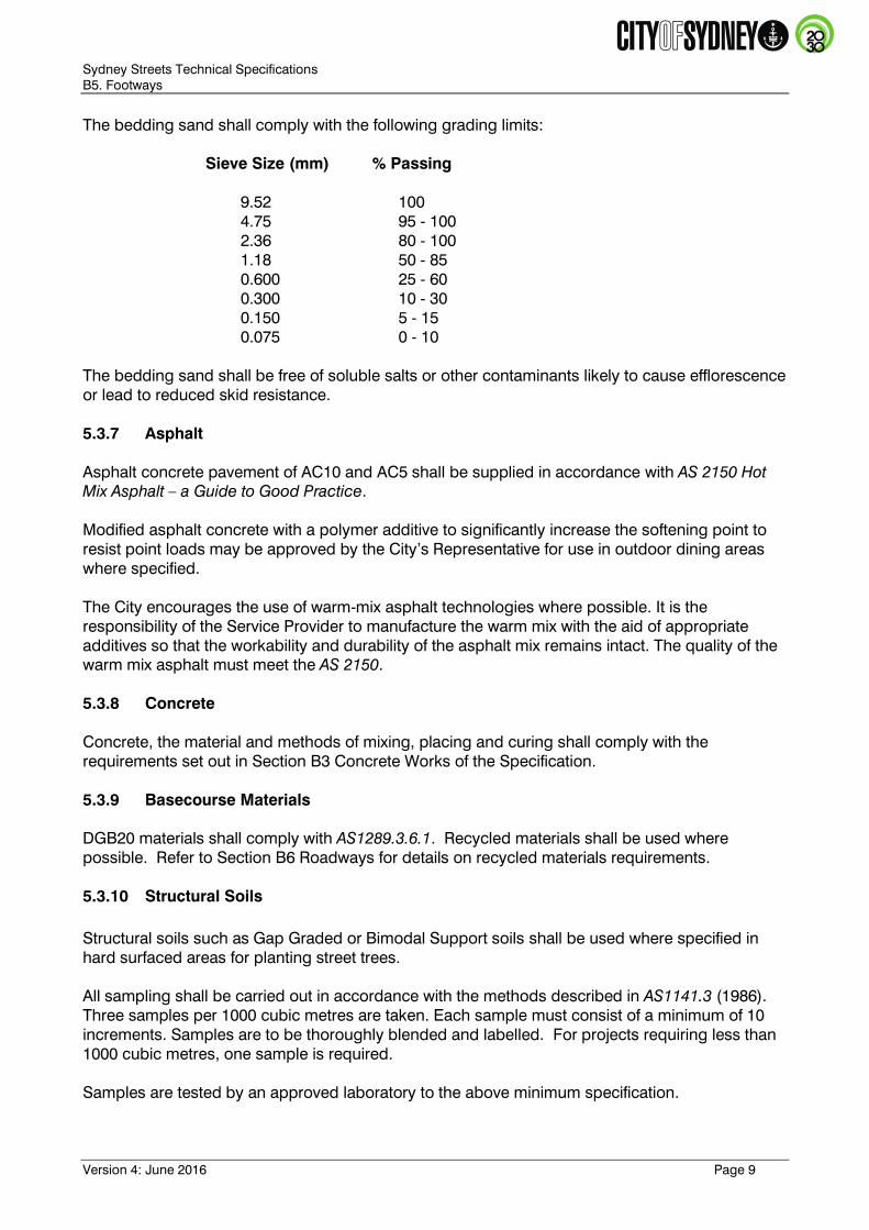
The bedding sand shall comply with the following grading limits:
Sieve Size (mm) % Passing
9.52 100
4.75 95 - 100
2.36 80 - 100
1.18 50 - 85
0.600 25 - 60
0.300 10 - 30
0.150 5 - 15
0.075 0 - 10
The bedding sand shall be free of soluble salts or other contaminants likely to cause efflorescence
or lead to reduced skid resistance.
5.3.7 Asphalt
Asphalt concrete pavement of AC10 and AC5 shall be supplied in accordance with AS 2150 Hot
Mix Asphalt – a Guide to Good Practice.
Modified asphalt concrete with a polymer additive to significantly increase the softening point to
resist point loads may be approved by the City’s Representative for use in outdoor dining areas
where specified.
The City encourages the use of warm-mix asphalt technologies where possible. It is the
responsibility of the Service Provider to manufacture the warm mix with the aid of appropriate
additives so that the workability and durability of the asphalt mix remains intact. The quality of the
warm mix asphalt must meet the AS 2150.
5.3.8 Concrete
Concrete, the material and methods of mixing, placing and curing shall comply with the
requirements set out in Section B3 Concrete Works of the Specification.
5.3.9 Basecourse Materials
DGB20 materials shall comply with AS1289.3.6.1. Recycled materials shall be used where
possible. Refer to Section B6 Roadways for details on recycled materials requirements.
5.3.10 Structural Soils
Structural soils such as Gap Graded or Bimodal Support soils shall be used where specified in
hard surfaced areas for planting street trees.
All sampling shall be carried out in accordance with the methods described in AS1141.3 (1986).
Three samples per 1000 cubic metres are taken. Each sample must consist of a minimum of 10
increments. Samples are to be thoroughly blended and labelled. For projects requiring less than
1000 cubic metres, one sample is required.
Samples are tested by an approved laboratory to the above minimum specification.
Sydney Streets Technical Specifications
B5. Footways
Version 4: June 2016 Page 10
5.3.11 Structural Cells
Structural cells or structural support cells may be used under the footpaths. The cells may be only used around the tree to provide room for root growth. Size, depth, materials and installation scope shall be submitted to City for approval in design stage of the projects.
5.4 Construction
5.4.1 General
Footways shall be constructed according to the following, depending on the paving type as
specified:
Stone and concrete unit pavers shall be laid with a 30mm thick 4:1 mortar bed as specified on
a 110mm 32MPa concrete base with SL72 reinforcing mesh. Pavers shall be laid with a 1 to
3mm gap between pavers. The concrete base thickness for driveways vary from 150 to
250mm as indicated on the standard details;
Clay brick pavers shall be laid with a 30mm sand bedding layer on a 150mm DGB20 flexible
base course with sand joints between pavers;
Asphalt footway pavements shall consist of either:
o Flexible pavement: - 15mm AC5 DG wearing course, 35mm AC10 DG intermediate course
and a 100mm DGB20 base course; or
o Rigid pavement - 25mm AC5 DG on a 110mm 32MPa concrete base with SL72 reinforcing
mesh, where specified.
In-situ concrete footway pavements shall consist of a 110mm 32MPa concrete base with SL72
reinforcing mesh on a 100mm DGB20 base.
5.4.2 Excavation of Existing Pavers
The Service Provider is responsible for excavating existing where necessary.
Pavers are to be excavated and removed by the Service Provider with great care, to avoid
damage to the paver. Pavers, free of other excavated material, are to be transported by the
Service Provider to the City’s stone storage yard and unloaded and stacked, by crane truck if
necessary, as directed by the City’s Representative.
Pavers to be reused on site can be stored on site if a suitable secure location is available, subject
to approval by the City’s Representative. Refer to Section B1 Preliminaries / General of the
Specification for on-site storage requirements.
5.4.3 Cutting and Preparation of Pavers
Storage: Store pavers so that they are protected from the weather and atmospheric
pollution, and in conditions that avoid staining, marking or damage to the pavers.
Cutting Units: Maintain sharp arises and accurate joints and margins.
Laying pavers: Perform the necessary cutting and shaping to the required sizes. Cut pavers so
as to fit neatly around all penetrations and fixtures including pit covers, lighting
Sydney Streets Technical Specifications
B5. Footways
Version 4: June 2016 Page 11
and traffic poles, signs and the like. Refer to standard drawings for minimum
unit lengths, band widths and facetted zones.
Protection: When laying the paving, protect all fixtures from damage, including pit covers,
lighting and traffic poles, signs and the like.
Noise and Dust: Refer to Section B1 Preliminaries / General of the Specification for requirements
for noise control and environmental protection.
Requirement: When cutting pavers provide dust-proof screens and covers to protect existing
finishes, adjacent buildings and the immediate environment from dust, noise and
debris. All cutting activities are to be situated away from residences and retail
traders.
Dry Cutting: The use of dry methods of cutting pavers on site is not permitted.
Wet Cutting: The use of wet methods of cutting pavers on site is permitted subject to
compliance with the requirements of the City of Sydney and AS2436-1981.
Prevent slurry run-off from wet cutting operations from marking or tracking
across adjacent paved areas. Collect residual water and slurry and divert them to
an approved means of disposal. Do not allow slurry to enter grates, gutters or
tree pits.
5.4.4 Subgrade
The Service Provider shall excavate or fill as may be required to bring the pavement bed to the full
specified depth below finished pavement level. All formation shall be thoroughly compacted as
below and shall be neatly trimmed true to line, level and cross slope, so as to provide for the full
specified thickness of pavement in all places.
Any soft or damp patches shall be removed and replaced with suitable imported fill material and
shall be thoroughly compacted to achieve a standard maximum dry density of 95% when tested in
accordance with AS1289 and a minimum CBR shear strength of 4%. Refer to Section B2
Earthworks of the Specification.
If the required strength and compaction is not able to be achieved then the Service Provider shall
replace and compact the top 75mm layer with DGB20 to meet the required compaction.
The subgrade shall be formed to the required profile as detailed in the standard details.
A subsoil drainage system shall be installed where specified.
5.4.5 Basecourses
The basecourse shall be specified flexible or rigid as follows:
Flexible base shall consist of a 100 to 150mm thick layer of DGB20 compacted to not less than
98% Standard Maximum Dry Density to AS1289; and
Rigid base shall consist of a 110mm 32 MPa concrete base with SL72 reinforcing mesh for
asphalt wearing course and pavers. A heavy broom finish shall be applied to the slab surface,
parallel with the fall of the slab for drainage and bonding purposes. Allow concrete base to
harden sufficiently, generally overnight, before laying pavers or applying asphalt course. The

Sydney Streets Technical Specifications
B5. Footways
Version 4: June 2016 Page 12
concrete base for driveways vary from 150 to 250mm in thickness as indicated on the
standard details.
Refer to standard drawings for details.
5.4.6 Structural Cells
The excavation for structural cells shall be minimum 400 mm wider than the actual cells at the base of the excavation. This allows for adequate compaction of the fill material around the structural cells. Construction methodology and procedure including but not limited to type of soil, drainage and compaction ration shall be approved by City prior to commencement of the construction.
5.4.7 Method of Laying Stone and Concrete Unit Pavers
Laying of pavers shall be carried out by an experienced and qualified Service Provider. Paver
laying procedures shall be conducted as follows:
Clean concrete base of any dirt or dust;
Moisten concrete base surface with a light spray of water. Pour a 1:1 cement water slurry mix
(bond coat) over concrete base prior to placing bedding mortar;
Mix thoroughly 4:1 sand: cement as a semi-dry ('earth-dry') mix mortar, ensuring a uniform mix
and sufficient strength (3-5MPa at 7 days). Prior to mixing, check sand is moist by squeezing
a handful and ensuring sand maintains its shape. Only sufficient bedding mix should be
prepared and laid to enable the laying operation to be completed within a reasonable time;
Place semi-dry mix mortar over slurry coat. Installation of mortar mix to be 10 to 15% higher
than required levels (or higher as necessary) prior to compaction of stone pavers;
Apply pre-mixed 1:1 cement water slurry mix to cover area of mortar to be paved. No delay in
laying of pavers after application of the cement slurry;
Paving units shall be laid surface dry on the slurry coated mortar bedding course with a joint
width of 1 to 3mm between adjacent pavers;
Tamp down paving units into position ensuring full contact with the mortar bed with minimum
deviation between edges of adjacent pavers; and
Check individual paver units for correct installation as work proceeds. Where stone pavers do
not align properly, are loose, drummy or rock, remove non-compliant pavers, remove mortar
bed (full depth) and repeat mortar bed and paver installation procedure again.
5.4.8 Method of Laying Brick Pavers
Brick pavers shall be placed on the uncompacted screeded sand bed to the nominated laying
pattern, with care being taken to maintain the specified bond throughout the works. Paving units
shall be placed such that all joints are correctly aligned.
Sand bedding:
The sand bedding shall be spread loose in a uniform layer screeded in a loose condition to a
level such that, after compaction, the pavers shall be at the correct levels and profiles;

Sydney Streets Technical Specifications
B5. Footways
Version 4: June 2016 Page 13
The spread sand shall be carefully maintained in a loose condition and protected against pre-
compaction both prior to and following screeding. Any pre-compacted sand or screeded
sand left overnight shall be loosened before further paving units are placed. The sand bed
shall not be screeded in advance of the laying face to an extent to which paving will not be
completed on that day; and
Screeded sand must be fully protected against accidental pre-compaction, including
compaction by rain or dew. Any screeded sand which is pre-compacted prior to laying of
units shall be removed and brought back to profile in a loose condition.
Compaction:
The paving units shall be compacted to achieve consolidation of the sand bedding
(approximately 10mm settlement), and brought to design levels and profiles by not less than
two passes of a high frequency, low amplitude mechanical flat plate vibrator having a plate
area sufficient to cover a minimum of 12 paving units;
Compaction shall proceed as closely as possible following laying and prior to the application
of any traffic;
Compaction should not be attempted within one metre of the laying face. Compaction shall
continue until lipping has been eliminated between adjoining units;
All work to within one metre of the laying face must be left fully compacted at the completion
of each days laying; and
Any units that are structurally damaged during compaction shall be immediately removed and
replaced.
Filling joints:
After compaction of the paving blocks and prior to the termination of work on that day and
prior to the application of any construction traffic, sand for joint filling shall be spread over the
pavement;
The joint filling sand shall be well graded sand passing a 2.36mm sieve and be suitable for
concrete manufacture. The joint filling sand shall be as dry as practicable when spread;
The joint filling sand shall comply with the following grading limits:
Sieve Size (mm) % Passing
2.36 100
1.18 90 - 100
0.600 60 - 90
0.300 30 - 60
0.150 15 - 30
0.075 5 - 10
The joint filling sand shall be free of soluble salts or other contaminants likely to cause
efflorescence or lead to reduced skid resistance; and
The filling sand shall be broomed to fill the joints and the pavement re-compacted to achieve
compaction of the joint filling sand. As the work proceeds joints shall be checked for
adequacy of filling and any shortfall shall be made good prior to further compaction taking
Sydney Streets Technical Specifications
B5. Footways
Version 4: June 2016 Page 14
place. Any excess surface sand shall be removed promptly from the surface of the paving
blocks.
5.4.9 Laying Arrangements
Stone and concrete unit pavers shall be laid with a joint width of 1 to 3mm between adjacent
pavers as shown in the standard details, unless specified otherwise. The expansion joint shall run
parallel to the kerb and gutter. Refer to standard drawings for make-p and facetted zones.
Brick pavers shall be laid with a joint width of 3mm between adjacent pavers in a 45 degree
Herringbone pattern unless specified otherwise.
5.4.10 Expansion and Contraction Joints
Expansion joints, 10mm in width, shall be constructed at the interface such as building line, back
of kerb and gutter, around services, or change in material.
All expansion and contraction joints shall be self-expanding joint filler approved by the City’s
Representative.
5.4.11 Edge Restraint for Brick Paving
Adjacent to free edges where paving units do not adjoin a hard paved surface, a mass concrete
edge restraint shall be provided. The concrete shall be finished at a level 35mm above the base
of the paver and shall be a minimum thickness of 100mm and depth of 200mm.
The adjacent ground shall be graded to meet the top of the paving.
5.4.12 Laying of Asphalt Paving
Asphalt concrete footways shall be laid in accordance AS 2150 Hot mix asphalt – A guide to good
practice.
Asphalt shall be compacted with, only, static (non-vibratory) self-propelled steel wheeled rollers
with a mass of rollers of 2 t to 3 t. Compaction by hand methods with tampers or vibrating plates
shall be limited to small areas inaccessible to rollers where approved by the City’s Representative.
Maximum layer thickness should be limited to those that will enable the specified density to be
achieved.
5.4.13 In-situ Concrete Paving
The Service Provider shall construct in-situ concrete paving as shown on the standard details and
as detailed in this Specification.
In-situ concrete paving for footpaths, vehicular crossings and kerb ramps shall be finished with a
medium broom.
In-situ concrete footpaths shall be a 110mm 32MPa concrete base with SL72 reinforcing mesh,
typically placed on a 100mm thick DGB20 base.
Sydney Streets Technical Specifications
B5. Footways
Version 4: June 2016 Page 15
All in-situ concrete paving slabs shall have a joint along the building line, kerb line and at any
penetrations. Expansions joints 10mm thick with an approved self-expanding joint filler shall
typically be provided at 4.5m – 5.4m spacings. Contraction joints comprising a 42mm deep
sawcut or dummy (tooled) joint shall be provided at 1.5m – 1.8m spacings.
Concrete footpaths shall be typically 1.8m wide unless directed otherwise by the City’s
Representative.
5.4.14 Cleaning
Generally: Leave clean on completion. Clean area progressively with hard sponges and
clean water as the work proceeds without using acid and without damage to
the work, as necessary to remove mortar smears, stains, discolouration and the
like. Ensure that all adjacent surfaces are left clean on completion, including
adjacent kerbs, pit covers, bitumen paving. Remove mortar smears from
adjacent surfaces.
Precautions during cleaning: Prevent run-off from the cleaning operations from marking or
tracking across adjacent paved areas. Collect residual water and cleaning
wastes and divert them to an approved means of disposal.
Requirement: Cleaning is to be undertaken, using one or more of the following methods:
Hydraulic;
Hydro-air; or
Steam-water jet.
Brushes may be necessary to remove certain surface impurities and fibre
brushes are recommended for this purpose.
Chemicals, which may damage the surface or do not comply with the relevant
EPA regulations, are not to be used.
The Service Provider is required to handover the paving to the City’s Representative at Practical
Completion in a clean condition. If the general public has been allowed access onto the paving
during the construction period, then the Service Provider must clean the paving ready for Practical
Completion.
5.4.15 Protective Sealant
A protective sealant of DuPont StoneTech Professional Heavy Duty Exterior Sealer or approved
equivalent shall be applied to seal the surface of all concrete, brick and stone unit paving. The
sealant shall be a penetrating type and protect the pavers from staining, ease cleaning and lower
maintenance frequency. The sealant shall not affect the paver’s colour or reduce its slip
resistance.
The penetrating sealant shall be applied to the surface including over any joint filler material as
soon as possible after being laid, and prior to opening the area to pedestrian use.
The sealant shall be applied as per the directions in manufacturer’s technical data sheet.
5.5 Vehicular Crossings (Driveways), Kerb Ramps and Stairs

Sydney Streets Technical Specifications
B5. Footways
Version 4: June 2016 Page 16
5.5.1 Removal
Where required and approved, driveways and kerb ramps shall be removed by excavating and
removing any existing kerb and gutter and / or layback and constructing new kerb and gutter
across the kerb opening prior to reconstruction of the footway and roadway.
The kerb, gutter and footway shall be constructed from material matching the kerb, gutter and
footway adjacent to the opening unless specified otherwise. The reconstructed areas must finish
flush with all adjacent surfaces.
5.5.2 Construction
Areas are to be excavated to required depth below finished levels and the subgrade compacted to
form a uniform working platform. Refer to Section B2 Earthworks for details.
Formwork is to be solidly set to enable the concrete base to be poured true to the required line
and level.
The bases of vehicular crossings or kerb ramps are to be separated from the concrete base of the
surrounding footway, or building line or kerb stones by a layer of 10 mm thick expansion joint filler
as shown in the standard details.
5.5.2.1 Vehicular Crossings (Driveways)
Vehicular crossings (driveways) shall be constructed as shown in the standard details.
During the construction of any vehicular crossing the Service Provider may be required to
undertake road restoration or reconstruct sections of footpath in the vicinity of the crossing and
layback.
In asphalt areas, where the adjacent footpath is asphalt, the driveway shall have a black oxide
mixed into the concrete, prior to pouring. The oxide is to be added in a ratio that changes the
concrete colour to a colour that matches the adjacent asphalt footpath.
5.5.2.2 Kerb Ramps
Kerb ramps shall be constructed in conjunction with the construction of the kerb and gutter. The
ramps shall be constructed according to the standard details and the Specification and in the
positions shown on the approved drawings or as otherwise directed by the City’s Representative.
In asphalt areas, where the adjacent footpath is asphalt, the kerb ramps shall have a black oxide
mixed into the concrete, prior to pouring. The oxide is to be added in a ratio that changes the
concrete colour to a colour that matches the adjacent asphalt footpath.
5.5.2.3 Reinforced Concrete Stairs
Concrete steps shall be constructed as specified in the approved plans. The concrete shall be
placed in one course to the full depth of the riser as shown in the approved plans and according
to Section B3 Concrete Works. Expansion joints shall extend the full depth of the slab in locations
as shown on the plans. The edges of such joints shall be finished with an edging tool having a
6mm radius.

Sydney Streets Technical Specifications
B5. Footways
Version 4: June 2016 Page 17
5.5.3 Surface Finish
Concrete shall be finished with a heavy broom finish shall be applied to the slab surface, parallel
with the fall of the slab for drainage and bonding with the asphalt finish.
Concrete laid as the final surface shall finished with a medium broom finish generally
perpendicular to line of travel, and edged.
5.6 Tactile Ground Surface Indicators (TGSIs)
Where required TGSIs shall comply and be installed as specified in the approved plans in
accordance with AS1428. Discrete Stainless Steel Hazard and Directional Tactile Ground Surface
Indicators shall be used unless specified otherwise.
The service provider shall ensure that directional tactile indicators comply with slip-resistance
requirements in both directions and the design and arrangement of all TGSIs shall be comply with
AS1428.4.1
Indicators shall be installed to the manufacturer’s recommendations.
5.7 Handrails
Where required, handrails shall comply and be installed as specified in the approved plans in
accordance with AS 1428.
5.8 Utility Covers
5.8.1 General
The Service Provider shall visit the site and confirm the locations, sizes and numbers of existing
utility pits.
All covers shall be recessed and in-filled with the paving material specifically cut to lie flush with
the cover edge and surrounding paving. Pattern shall continue through the lid, perpendicular to
the frame where possible. Infill lids in granite shall be constructed as per the standard drawings.
It is the Service Providers responsibility to notify the relevant service authority when working
around their respective infrastructure.
5.8.2 Adjustment and Relocation
Where the level of the footpath or roadway is altered from its existing level, adjust and relocate all
the existing pit frames and covers that are to be retained so as to finish flush with the adjacent
finished footpath or road surface.
Ensure that the existing pit frames and pit covers that are to be reused are free from rust and free
from twists or warps, which would result in uneven seating of the pit covers when relocated.
Where granite paving is to be installed, metal lids are to remain and all infill lids are to be granite
infill as per the standard drawings.
All utility companies should be contacted regarding realignment of utility covers and coordinated
prior to commencement of works.

Sydney Streets Technical Specifications
B5. Footways
Version 4: June 2016 Page 18
5.8.3 Authority Standards
All pit covers are to comply with the standards and requirements of the relevant service authority.
Refer to Section B1 Preliminaries / General of the Specification. All work on existing and new pits
typically requires only the use of subcontractors who are approved by the asset owner.
5.8.4 Loadings
For pit covers in the footpath use loading Class C, 150kN, unless noted otherwise. Driveway pit
lids to have higher load carrying capacity and comply with Class ‘D’ loading of the pit lids . Install
as per relevant service authority requirements. Refer to standard details.

Sydney Streets Technical Specifications
B5. Footways
Version 4: June 2016 Page 19
5.9 Quality
5.9.1 Load Testing
No pavers or stonework are to move or rock under pedestrian, wheel chair, typical delivery trolley
or test loading. The Service Provider is to test load each completed lot (section) of paving to
determine the extent of any unbonded, loose or defective pavers.
Test loading method to be as follows:
General Footpath
Loading vehicle: City of Sydney Footpath Cleaning Machine (5 tonne, gross), fully loaded
with cleaning liquid;
Number of passes: 4 passes; and
Acceptance criteria: No visible movement in the pavers, cracks, or other forms of failure.
Driveways
Loading vehicle: 8 tonne (gross) truck, fully loaded;
Number of passes: 4 passes; and
Acceptance criteria: No visible movement in the pavers, cracks or other forms of failure.
Rectification to be as follows:
Less than 10% of lot (section) area fails load test: Remove and relay individual pavers on new
mortar bedding. Retest lot (section) area; or
10% or more of lot (section) area fails load test: Remove and relay entire lot (section).
5.9.2 In-situ Slip Resistance Testing of New Surfaces
The Service Provider shall test the in-situ slip resistance of the new unit paving according to
AS/NZS 4586, once the pavement has been sealed. The Service Provider shall test a minimum of
five locations for each site condition that is tested. The Service Provider shall seek agreement of
specific test locations from the City’s Representative before testing.
The following minimum slip resistance shall be achieved for new surface and jointing material:
Test Condition Test Method Class Description
Wet Pendulum Appendix A P4 Low Risk
Pavements that do not meet the above minimum slip resistance shall be reground and rectified at
the Service Provider’s own expense.

Sydney Streets Technical Specifications
B5. Footways
Version 4: June 2016 Page 20
5.9.3 Inspections
Give at least two working days notice for all inspections
5.9.3.1 Hold and Witness Points
Construct New Paved Footway
1. Process Held: Set-out and excavation complete (Section 5.4.2)
Submission Details: At least two (2) day before commence excavation.
Release of Hold Point: The City’s Representative will inspect the excavation,
prior to authorising the release of the Hold Point.
2. Process Held: Compaction of Subgrade (Section 5.4.4)
Submission Details: At least two (2) working days prior compaction of
subgrade.
Release of Witness Point: The City’s Representative will inspect the compacted
subgrade, prior to authorising the release of the Witness
Point unless advised otherwise.
3. Process Held: Placement and compaction of DGB Basecourses where
required for flexible pavements (Section 5.4.5)
Submission Details: At least two (2) working days prior placing and
compaction of DGB base.
Release of Witness Point: The City’s Representative will inspect the compacted
DGB Base, prior to authorising the release of the Witness
Point unless advised otherwise.
4. Process Held: Installing concrete formwork and reinforcements where
required. (Section 5.4.12)
Submission Details: At least two (2) working days prior to installing concrete
formwork.
Release of Hold Point: The City’s Representative will inspect the concrete forms
and reinforcements shall be made, prior to authorising
the release of the Hold Point.
5. Process Held: Placement of concrete (Section 5.4.12)
Submission Details: At least two (2) working days prior to placing concrete.
Release of Witness Point: The City’s Representative will inspect concrete finish
levels and expansion joints, prior to authorising the
release of the Witness Point unless advised otherwise.
6. Process Held: Preparation of sand or mortar bedding layer (Section
5.9.1)
Submission Details: At least two (2) working days prior placing pavers.
Release of Witness Point: The City’s Representative will inspect mortar strength
tests or sand bedding thickness, prior to authorising the
release of the Witness Point unless advised otherwise.
7. Process Held: Laying of pavers (Section 5.4.10 and 5.4.11)

Sydney Streets Technical Specifications
B5. Footways
Version 4: June 2016 Page 21
Submission Details: At least two (2) working days prior to laying of pavers.
Release of Hold Point: The City’s Representative will inspect finish including
levels, joints, and sealant, prior to authorising the release
of the Hold Point.
5.9.3.2 Tolerances
All surfaces shall be finished in conformity with the lines, grades, thicknesses and cross sections
shown on the drawings or specified or directed by the City’s Representative within the following
limits:
Item Activity Tolerances
1. Footpath
a. Surface Level
The deviation of the finished work from line or level
shall not exceed 20mm in 10m
No steps in the footpath or between any two
adjacent pavers shall be more than 2mm;
On curves or in shaped areas, the deviation of the
finished work from a 3m straightedge shall not
exceed 15mm at any point;
The slope at any point on the surface shall not be
less that 1% and not exceed 3%; and
Unless otherwise specified or directed, the finished
surfaces shall be shaped to shed surface water from
the entire area in the directions of the natural slope
or towards the constructed surface drains.
2. Tie-in at Features
a. Surface Level
The finished surface shall be shaped to match
existing features e.g. pit covers, edgings and
driveways, within 2 mm.
3. Paving Alignment
a. Surface level
The alignment of the paving shall not differ from the
specified line by more than +/-50mm, provided that
the minimum pavement width is achieved at all
points throughout the construction.
Note: Material tolerances are included in Section 5.3 of this specification.