ba 035d/06/en/01.98 no. 50085724 promag 35...
TRANSCRIPT

promag 35(PROFIBUS PA)ElectromagneticFlow Measuring SystemOperating Manual
E – +
ENDRESS+HAUSERPROMAG
>3s
Hauser+EndressNothing beats know-how
BA 035D/06/en/01.98No. 50085724CV 5.0
valid from software versionV 3.01.XX (amplifier)V 2.05.XX (communication)
Short Instruction
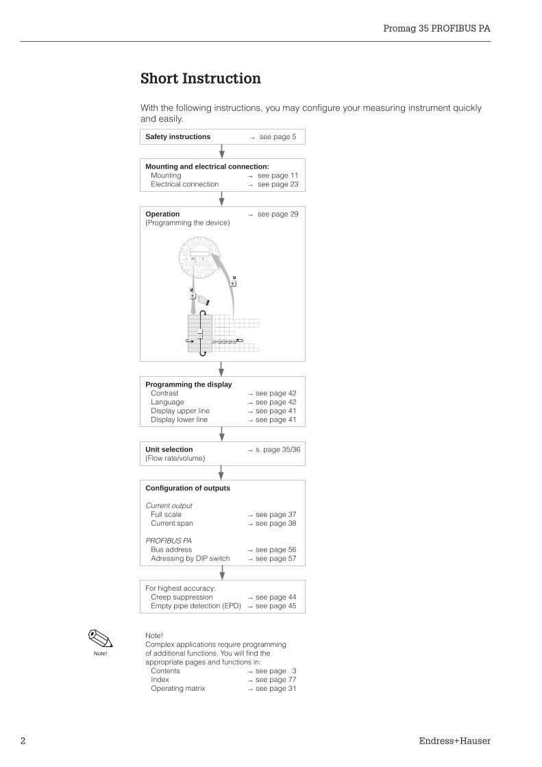
With the following instructions, you may configure your measuring instrument quicklyand easily.
Note!
Safety instructions → see page 5
Mounting and electrical connection:Mounting → see page 11Electrical connection → see page 23
Operation → see page 29(Programming the device)
Programming the displayContrast → see page 42Language → see page 42Display upper line → see page 41Display lower line → see page 41
Unit selection → s. page 35/36(Flow rate/volume)
Configuration of outputs
Current outputFull scale → see page 37Current span → see page 38
PROFIBUS PABus address → see page 56Adressing by DIP switch → see page 57
For highest accuracy:Creep suppression → see page 44Empty pipe detection (EPD) → see page 45
Note!Complex applications require programmingof additional functions. You will find theappropriate pages and functions in:
Contents → see page 3Index → see page 77Operating matrix → see page 31
E - +
E E E E E
+
-
E
>3s
E
Promag 35 PROFIBUS PA
2 Endress+Hauser

InhaltsverzeichnisContents
1 Safety Instructions . . . . . . . . 51.1 Correct usage . . . . . . . . . . . 51.2 Dangers and notes . . . . . . . . . 51.3 Personnel for installation, start-up and
operation . . . . . . . . . . . . . 51.4 Repairs, dangerous chemicals . . . . . 61.5 Technical improvements . . . . . . . 6
2 System Description . . . . . . . 72.1 Correct usage . . . . . . . . . . . 72.2 Promag 35 S measuring system . . . . 72.3 Design of the measuring system . . . . 8
3 Mounting and Installation . . . 113.1 General information . . . . . . . . . 113.2 Transport instructions (for DN > 200/8") . 123.3 Mounting instructions . . . . . . . . 133.4 Mounting Promag 35 S . . . . . . . . 163.5 Turning the transmitter housing and local
display (compact version) . . . . . . . 183.6 Mounting the transmitter (remote version) 193.7 Potential equalisation . . . . . . . . 20
4 Electrical Connection . . . . . 234.1 Connecting the transmitter for the
compact version . . . . . . . . . . 234.2 Connection diagrams . . . . . . . . 244.3 Connection diagram for the remote version 254.4 Cable specifications . . . . . . . . . 264.5 Commissioning . . . . . . . . . . . 27
5 Operation . . . . . . . . . . 295.1 Operating and display elements . . . . 295.2 Functions of the operating elements . . . 305.3 Programming matrix Promag 35
PROFIBUS PA . . . . . . . . . . . 315.4 Information for programming . . . . . . 325.5 Programming example . . . . . . . . 33
6 Functions . . . . . . . . . . . 35
7 PROFIBUS PA Interface . . . . . 557.1 PROFIBUS PA . . . . . . . . . . . 557.2 GSD- and Type-Files . . . . . . . . . 557.3 Setting the bus address . . . . . . . 567.4 PROFIBUS PA addressing via touch control 567.5 Addressing PROFIBUS PA by DIP switches 577.6 PROFIBUS PA Parameters . . . . . . 58
8 Troubleshooting and Remedies . 598.1 Response of the measuring system to
faults or alarm . . . . . . . . . . . 598.2 Instructions for troubleshooting . . . . . 608.3 Diagnostic function for fault location . . . 618.4 Error and status messages . . . . . . 628.5 Replacing the fuse . . . . . . . . . . 648.6 Repairs . . . . . . . . . . . . . . 64
9 Dimensions and Weights . . . . 65
10 Technical Data . . . . . . . . 69
11 Index . . . . . . . . . . . . 77
Promag 35 PROFIBUS PA
Endress+Hauser 3

Registered Trademarks
HART®
Registered Trademark of HART Communication Foundation, Austin, USA
KALREZ®, VITON
®and TEFLON
®
Registered Trademark of E.I. Du Pont de Nemours & Co., Wilmington, USA
PROFIBUS®
Registered Trademark of PROFIBUS Nutzerorganisation e.V., Karlsruhe, Germany
TRI-CLAMP®
Registered Trademark of Ladish & Co., Inc., Kenosha, USA
Promag 35 PROFIBUS PA
4 Endress+Hauser

1 Safety Instructions
1.1 Correct usage
• The Promag 35 S is only to be used for measuring the flow of conductive fluids.• The manufacturer assumes no liability for damage caused by incorrect use of the
instrument.
1.2 Dangers and notes
All instruments are designed to meet state-of-the-art safety requirements, have beentested, and have left the factory in an operational perfectly safe condition.
The devices were developed according to EN 61010 “Protection Measures forElectronic Equipment for Measurement, Control, Regulation and LaboratoryProcedures”.A hazardous situation may occur if the flowmeter is not used for the purpose it wasdesigned for or is used incorrectly.Please carefully note the information provided in this Operating Manual indicated bythe pictograms:
Warning!A “warning” indicates actions or procedures which, if not performed correctly, maylead to personal injury or a safety hazard.Please strictly observe the instructions supplied and proceed carefully.
Caution!A “caution” indicates actions or procedures which, if not performed correctly, maylead to faulty operations or the destruction of the instrument.Please strictly observe the respective instructions.
Note!A “note” indicates actions or procedures which, if not performed correctly, mayindirectly affect operations or lead to an unexpected instrument response.
1.3 Personnel for installation, start-up and operation
• Mounting, electrical installation, start-up and maintenance of the instrument mayonly be carried out by trained personnel authorised by the operator of the facility.Personnel must absolutely and without fail read and understand this OperatingManual before carrying out its instructions.
• The instrument may only be operated by personnel who are authorised and trainedby the operator of the facility. All instructions in this manual are to be observedwithout fail.
• With special fluids, incl. those used for cleaning, E+H will be pleased to supplyinformation concerning the chemical resistance properties of wetted parts.
Warning!
Caution!
Note!
Promag 35 PROFIBUS PA 1 Safety Instructions
Endress+Hauser 5

• The installer has to make sure that the measuring system is correctly wired upaccording to the wiring diagrams. The measuring system is to be grounded.
• Please observe all provisions valid for your country and pertaining to the openingand repairing of electrical devices.
1.4 Repairs, dangerous chemicals
The following procedures must be carried out before a Promag 35 S is sent toEndress+Hauser for repair:• A note must always be enclosed with the instrument, containing a description of the
fault, the application, and the chemical and physical properties of the product be-ing measured.
• Remove all residue which may be present. Pay special attention to the gasketgrooves and crevices where fluid may be present. This is especially important ifthe fluid is dangerous to health, e.g. corrosive, carcinogenic, radioactive, etc.
• No instrument should be returned without all dangerous material beingremoved first (e.g. in scratches or diffused through plastic).
Incomplete cleaning of the instrument may result in waste disposal or cause harm topersonnel (burns, etc). Any costs arising from this will be charged to the owner of theinstrument.
1.5 Technical improvements
The manufacturer reserves the right to modify technical data without prior notice. Yourlocal E+H Sales Office will supply you with all current information and any updates tothis Operating Manual.
Danger of electric shock!Protection against accidental contact is no longer assured when the
connection housing cover is unscrewed.
1 Safety Instructions Promag 35 PROFIBUS PA
6 Endress+Hauser

2 System Description
2.1 Correct usage
The Promag 35 S measuring system is used whenever a system has to meet highrequirements. It is particularly suitable for media characterised by a high solids content,high abrasiveness, and a highly inhomogeneous distribution of additives and chemicals.Any fluids with a minimum conductivity of ≥ 1 µS/cm, ≥ 20 µS/cm for demineralised anddesalinised water, may be measured.For difficult-to-measure media, Promag 35 S is mainly used for the following applications:
Paper and pulp industry pulp with 15% solids contents, cellulose,additives/chemicals
Mining industry ore slurries, coal washings
Building material industry cement, concrete, pastes
Food industry yoghurt with pieces of fruit, fruit mash
Sewage industry slurries of up to 30% dry solids
2.2 Promag 35 S measuring system
The Promag measuring system is fully modular, both electrically and mechanically.The measuring system can be updated at any time by exchanging electronic boards.The measuring point can always be optimally equipped and upgraded.The following illustration is an overview of the entire Promag 35 S measuring system.
Note!For standard applications, the cost-effective Promag 30 version is available or the con-venient Promag 33 version with the E+H matrix operation mode.All information on these measuring systems are available from your E+Hrepresentative.
Note!
ENDRESS+HAUSERPROMAG
ENDRESS+HAUSERPROMAG
Sensorba
035y
02
Power supply board180...260 V AC or
Power supply board85...130 V AC, or
Power supply board20...55 V AC,16...62 V DC
Measuring amplifier board
Communication board withPROFIBUS PA interface andactive current output
Display/operating module(blind version: without display/operating module optional)
Equipment of the transmitter Promag 35 S
DN 15...200
DN 250...600
Fig. 1Promag 35 S PROFIBUS PAmeasuring system
Promag 35 PROFIBUS PA 2 System Description
Endress+Hauser 7
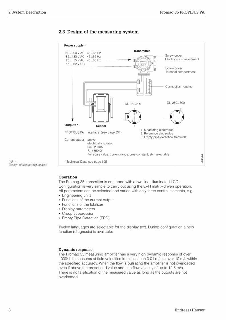
2.3 Design of the measuring system
OperationThe Promag 35 transmitter is equipped with a two-line, illuminated LCD.Configuration is very simple to carry out using the E+H matrix-driven operation.All parameters can be selected and varied with only three control elements, e.g.• Engineering units• Functions of the current output• Functions of the totalizer• Display parameters• Creep suppression• Empty Pipe Detection (EPD)
Twelve languages are selectable for the display text. During configuration a helpfunction (diagnosis) is available.
Dynamic responseThe Promag 35 measuring amplifier has a very high dynamic response of over1000:1. It measures at fluid velocities from less than 0.01 m/s to over 10 m/s withinthe specified accuracy. When the flow is pulsating the amplifier is not overloadedeven if above the preset end value and at a flow velocity of up to 12.5 m/s.There is no falsification of the measured value as long as the outputs are notoverloaded.
ENDRESS+HAUSERPROMAG33
ba03
5y04
Outputs *
PROFIBUS PA interface (see page 55ff)
Current output activeelectrically isolated0/4...20 mARL <350 ΩFull scale value, current range, time constant, etc. selectable
* Technical Data: see page 69ff
1 Measuring electrodes2 Reference electrodes3 Empty pipe detection electrode
Power supply *
180...260 V AC 45...65 Hz85...130 V AC 45...65 Hz20... 55 V AC 45...65 Hz16... 62 V DC
Screw coverElectronics compartment
Sensor
Screw coverTerminal compartment
Connection housing
Transmitter
11
3
2
13
12
DN 15...200 DN 250...600
Fig. 2Design of measuring system
2 System Description Promag 35 PROFIBUS PA
8 Endress+Hauser

Operational safety• A comprehensive measuring system self-monitoring facility assures high availability.
Any system errors (coil current error, amplifier error, DAT error, EEPROM error,ROM error, RAM error) or power supply failures that do occur are immediatelysignalled via the PROFIBUS PA interface or the fail-safe mode of the current output.
• Corresponding error messages also appear on the transmitter display. By means ofthe diagnostic function any errors present can be systematically scanned and theircause determined.
• In the event of a power supply failure, all data in the measuring system are safelystored in the EEPROM (no batteries required).
• The Promag 35 S measuring system fulfils the safety requirements accordingto EN 61010 “Protection Measures for Electronic Equipment for Measurement,Control, Regulation and Laboratory Procedures”, as well as the general require-ments for electromagnetic compatibility (EMC) according to EN 50081 Part 1 andPart 2 / EN 50082 Part 1 and Part 2 as well as the NAMUR recommendations.
Data Memory (DAT)The DAT is an exchangeable memory module. It stores all characteristic dataof the sensor, such as calibration factors, nominal diameter, sampling rate, version,serial number. When the transmitter has been changed, the previous DAT is insertedin the new transmitter. When the measuring system is started, the measuring pointcontinues to operate with the data stored in the DAT memory. Thus, the DATassures maximum safety and optimum ease of operation when components of theequipment are exchanged.
Promag 35 PROFIBUS PA 2 System Description
Endress+Hauser 9

2 System Description Promag 35 PROFIBUS PA
10 Endress+Hauser

3 Mounting and Installation
Warning!The instructions given in this section are to be observed at all times in order toensure safe and reliable operation of the measuring system.
3.1 General information
Degree of protection IP 65 (EN 60529)The instruments fulfil all the requirements for IP 65. After successful installation inthe field or after servicing, the following points must always be observed in orderto ensure the degree of protection IP 65:
• Housing gaskets must be clean andundamaged when inserted in thegasket groove. The gaskets may needto be dried, cleaned or replaced.
• All housing screws and the housingcover must be tightened firmly.
• The cables used for connecting musthave the correct outer diameter (seepage 26).
• The cable gland must betightened firmly (see Fig. 3).
• The cable must loop down beforeentering the cable gland to ensure thatno moisture can enter it (see Fig. 3).
• Any cable gland not used must bereplaced with a blind plug.
• The protective bushing should notbe removed from the cable gland.
Caution!The screws of the Promag sensor housing must not be loosened or the degree ofprotection guaranteed by E+H is no longer valid.
Note!The Promag 35 S sensor can optionally be supplied with the IP 67 or IP 68 degree ofprotection (permanently under water to a depth of 3 m). In this case the transmitter(generally supplied in IP 67) has to be mounted remote from the sensor.
Temperature rangesThe maximum approved ambient and process temperatures must be observed(see page 71). An all-weather cover should be used to protect from direct sunlightwhen mounting in the open.
Warning!
Caution!
Note!
ba03
5y05
Fig. 3Mounting cable entries
Promag 35 PROFIBUS PA 3 Mounting and Installation
Endress+Hauser 11

3.2 Transport instructions (for DN > 200/8")
The pipe lining on the flanges is protected by disks to prevent damage whentransporting to the measuring point. These are to be removed when installing.Instruments are to be transported in the containers they are delivered in.
Transporting to the measuring point• The grips on the flange must be used
when lifting the sensor and wheninstalling the sensor in the pipeline(from DN 200/8").
• The sensor must not be lifted by thetransmitter housing.
• The sensor must not be lifted by themetal casing using a fork lift truck.The casing may be dented and sodamage the magnetic coils inside thesensor.
Base support for the sensorThe sensor should stand on a basestrong enough to support its weight.
Note!Do not support the sensor by its metalcasing! The casing may be dented andso damage the magnetic coils inside thesensor.
ba03
5y07Fig. 4
Transport instructions forPromag 35 S
ba03
5y08Fig. 5
Correct sensor supporting forlarge diameter
Note!
3 Mounting and Installation Promag 35 PROFIBUS PA
12 Endress+Hauser

3.3 Mounting instructions
Please observe the following instructions when mounting for correct operation and toprevent damage to the equipment.
Mounting position (as preferred)a) Vertical:
This is the best with the flowdirection upwards. Entrainedsolids sink downward and fattycomponents in the stationaryfluid always rise away from themeasuring electrodes.
In case of vertical mounting, thePGs are always pointing downward(inlet side).
b) Horizontal:The axis of the electrodes mustbe horizontal, thus preventing briefinsulation of the electrodes byentrained air bubbles.
Position of the electrode axisThe position of the electrode axis isbased on the nominal diameter andhas to be respected (see Fig. 7).
Position of the cable glandsFor the compact version, the transmitterPGs have to be either oriented down-wards or laterally, independently of themounting position.
VibrationSecure the piping upstream anddownstream of the sensor.
Caution!Excessive vibration necessitatesseparate mounting of the sensor andtransmitter (see pages 19, 71).
Mechanical supports are recommendedfor free runs of piping over 10 m long.
ba03
5y09
a)
b)
Fig. 6Mounting position
ba03
5y10
1 Measuring electrodes2 Reference electrode (from DN 25)3 EPD electrode4 Connection housing
Fig. 7Plane of electrode axis
> 10 m
ba03
5y11
Fig. 8Remedies to avoid vibrations
Caution!
Promag 35 PROFIBUS PA 3 Mounting and Installation
Endress+Hauser 13
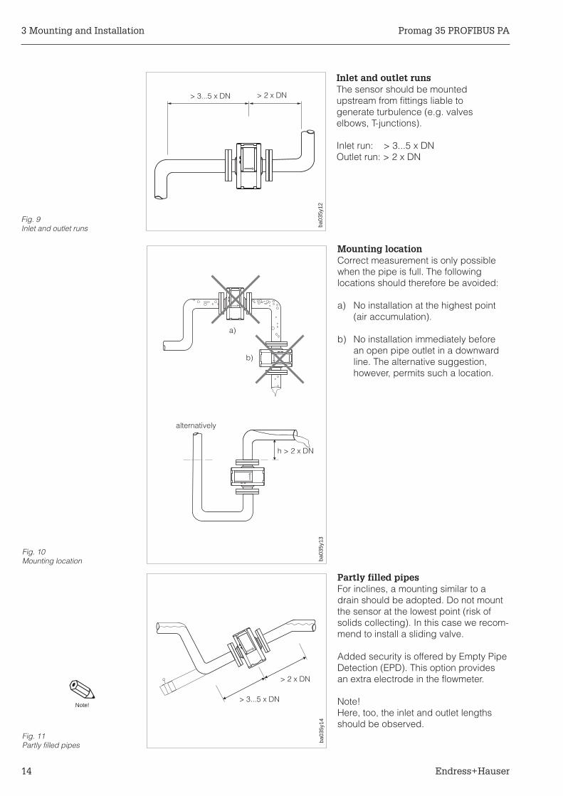
Inlet and outlet runsThe sensor should be mountedupstream from fittings liable togenerate turbulence (e.g. valveselbows, T-junctions).
Inlet run: > 3...5 x DNOutlet run: > 2 x DN
Mounting locationCorrect measurement is only possiblewhen the pipe is full. The followinglocations should therefore be avoided:
a) No installation at the highest point(air accumulation).
b) No installation immediately beforean open pipe outlet in a downwardline. The alternative suggestion,however, permits such a location.
Partly filled pipesFor inclines, a mounting similar to adrain should be adopted. Do not mountthe sensor at the lowest point (risk ofsolids collecting). In this case we recom-mend to install a sliding valve.
Added security is offered by Empty PipeDetection (EPD). This option providesan extra electrode in the flowmeter.
Note!Here, too, the inlet and outlet lengthsshould be observed.
> 3...5 x DN > 2 x DN
ba03
5y12
Fig. 9Inlet and outlet runs
alternatively
h > 2 x DN
ba03
5y13
a)
b)
Fig. 10Mounting location
> 3...5 x DN
> 2 x DN
ba03
5y14
Fig. 11Partly filled pipes
Note!
3 Mounting and Installation Promag 35 PROFIBUS PA
14 Endress+Hauser

Downward pipeWith the installation suggested opposite,partial vacuum is avoided even with adownward pipe >5 m long (siphon, ventvalve downstream of the sensor).
Installation of pumpsDo not mount the sensors on thesuction side of pumps. There is a risk ofvacuum! Information on the resistanceto vacuum of the flowmeter lining can befound on page 73.
AdaptersThe sensor can also be mounted in apipe with a larger nominal diameterwhen suitable adapters (reducers andexpanders) to DIN 28545 are fitted. Theresultant increase in the rate of flowincreases the accuracy of measurementwith slowly moving fluids.
The adjacent nomogram can be used todetermine the pressure loss caused.
Procedure:1. Determine the ratio of the
diameter d/D.2. From the nomogram read off the
pressure loss at the flow velocityand d/D ratio.
Note!The nomogram applies to fluids with aviscosity similar to that of water.
ba03
5y15
Venting valve
>5 m
Fig. 12Installation downward pipe
ba03
5y17
ba03
5y16
Fig. 13Installation of pumps
1
1 m/s
2 m/s
3 m/s
4 m/s
5 m/s
6 m/s
7 m/s
8 m/s
0.5 0.60.6 0.7 0.8 0.9
10
100
max.8°
Diameter ratio d/D
Pre
ssur
elo
ssin
mb
ar
Fig. 14Adapters
Note!
Promag 35 PROFIBUS PA 3 Mounting and Installation
Endress+Hauser 15
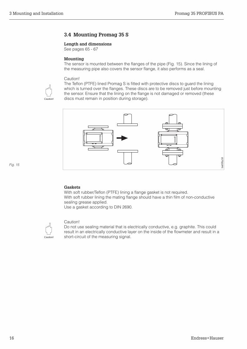
3.4 Mounting Promag 35 S
Length and dimensionsSee pages 65 - 67
MountingThe sensor is mounted between the flanges of the pipe (Fig. 15). Since the lining ofthe measuring pipe also covers the sensor flange, it also performs as a seal.
Caution!The Teflon (PTFE) lined Promag S is fitted with protective discs to guard the liningwhich is turned over the flanges. These discs are to be removed just before mountingthe sensor. Ensure that the lining on the flange is not damaged or removed (thesediscs must remain in position during storage).
GasketsWith soft rubber/Teflon (PTFE) lining a flange gasket is not required.With soft rubber lining the mating flange should have a thin film of non-conductivesealing grease applied.Use a gasket according to DIN 2690.
Caution!Do not use sealing material that is electrically conductive, e.g. graphite. This couldresult in an electrically conductive layer on the inside of the flowmeter and result in ashort-circuit of the measuring signal.
Caution!
Caution!
ba03
5y18
Fig. 15
3 Mounting and Installation Promag 35 PROFIBUS PA
16 Endress+Hauser

Screw tightening torquesThe listed tightening torques apply to greased threads.Screws tightened too tightly deform the sealing surface (this applies especially to softrubber).
DN Pressure ratings Screws Max. tightening torques [Nm]
[mm] [inch] DIN[bar]
ANSI[lbs]
AWWA JIS Hard rubber Soft rubber(EPDM)
PTFE(Teflon)
15 1/2" PN 40 – – – 4 x M 12 – – 15
25324050
1"–
11/2"2"
PN 16 Class150
–20K20K20K10K
4 x M 124 x M 164 x M 164 x M 16
25405064
58
1115
33536784
6580
100125150
–3"4"–6"
PN 16Class150 – 10K
4 x M 168 x M 168 x M 168 x M 168 x M 20
87536580
110
2214223048
1147085
103140
200250300
8"10"12"
PN 10Class150 –
10K––
12 x M 2012 x M 2012 x M 20
108104119
532939
137139159
350400–
500600
14"16"18"20"24"
PN 10Class150 – –
16 x M 2016 x M 2420 x M 2420 x M 2420 x M 27
141192170197261
39605870
108
188255227262348
Promag 35 PROFIBUS PA 3 Mounting and Installation
Endress+Hauser 17
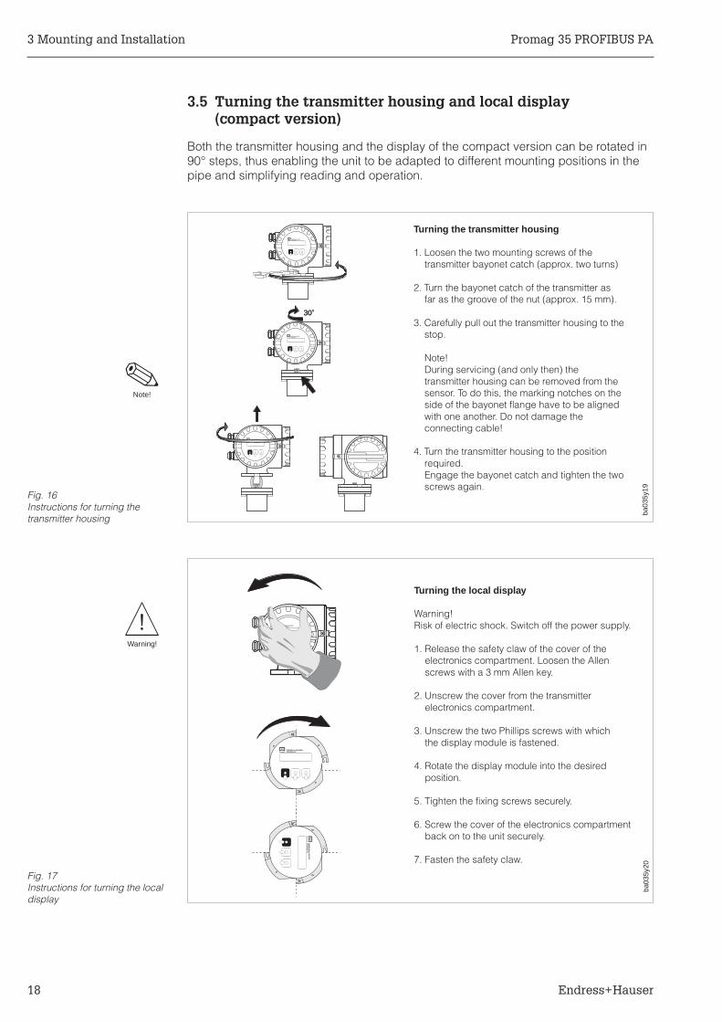
3.5 Turning the transmitter housing and local display(compact version)
Both the transmitter housing and the display of the compact version can be rotated in90° steps, thus enabling the unit to be adapted to different mounting positions in thepipe and simplifying reading and operation.
30o30o
ENDRESS+HAUSERPROMAG33
ENDRESS+HAUSERPROMAG33
ENDRESS+HAUSERPROMAG33
Turning the transmitter housing
1. Loosen the two mounting screws of thetransmitter bayonet catch (approx. two turns)
2. Turn the bayonet catch of the transmitter asfar as the groove of the nut (approx. 15 mm).
3. Carefully pull out the transmitter housing to thestop.
Note!During servicing (and only then) thetransmitter housing can be removed from thesensor. To do this, the marking notches on theside of the bayonet flange have to be alignedwith one another. Do not damage theconnecting cable!
4. Turn the transmitter housing to the positionrequired.Engage the bayonet catch and tighten the twoscrews again.
ba03
5y19
ba03
5y20
Fig. 16Instructions for turning thetransmitter housing
ENDRESS+HAUSERPROMAG33
EN
DR
ES
S+H
AU
SE
RP
RO
MA
G33
ENDRESS+HAUSERPROMAG33
Turning the local display
Warning!Risk of electric shock. Switch off the power supply.
1. Release the safety claw of the cover of theelectronics compartment. Loosen the Allenscrews with a 3 mm Allen key.
2. Unscrew the cover from the transmitterelectronics compartment.
3. Unscrew the two Phillips screws with whichthe display module is fastened.
4. Rotate the display module into the desiredposition.
5. Tighten the fixing screws securely.
6. Screw the cover of the electronics compartmentback on to the unit securely.
7. Fasten the safety claw.
Fig. 17Instructions for turning the localdisplay
Warning!
Note!
3 Mounting and Installation Promag 35 PROFIBUS PA
18 Endress+Hauser

3.6 Mounting the transmitter(remote version)
The transmitter has to be mounted remote from the sensor when:• access is difficult• space is restricted• extreme process and ambient temperatures prevail (for temperature ranges see
page 71)• there is severe vibration (tested according to EN 61010 and IEC 68-2-6)
Caution!• The permissible length Lmax of cable between the sensor and the transmitter at a
distance of >10 m is governed by the fluid conductivity (Fig. 19).• The overall conductor resistance of the coil-loaded cable has to be RCu max ≤2.5 Ω.
With the coil-loaded cable available from E+H, the maximum admissible distance isLmax = 50 m between sensor and transmitter.
• With the Empty Pipe Detection (EPD) the maximum possible cable lengthbetween transmitter and sensor is limited to 10 m.
• Fasten the cable gland or lay it in a conduit. When the fluid conductivity is low,cable movements can cause serious changes in capacitance and thereby falsifythe measuring signal.
• Do not run the cable in the vicinity of electrical machines or switching elements.• Ensure potential equalization between the transmitter and the sensor.
Caution!
ENDRESS+HAUSERPROMAG33
Transmitter housing
Connection housing
Wall mounting
Cableglands
ba03
5y22
Abb. 18Fixing the wall-mounted holder
50
25
1
10 25 50
Lmax
Permissiblerange
Cable length Lmax [m]
Conductivity[µS/cm]
9y24
ba03
5y21 Fig. 19
Cable length of the remoteversion
Promag 35 PROFIBUS PA 3 Mounting and Installation
Endress+Hauser 19

3.7 Potential equalisation
The sensor and the fluid must be at roughly the same electrical potential to ensurethat the measurement is accurate and no galvanic erosion takes place at theelectrodes. Normally the reference electrode in the sensor or the metal pipe ensuresthat the potentials are equalised. When an reference electrode exists and for fluidcarried in grounded metal piping it is sufficient to connect the ground terminal of thePromag 35 transmitter housing to the potential equalisation grid. Depending on thematerial used for the reference electrode, the electrode is already intergrated into thesensor or available as an option. For the DN 15 device, you will have to use ground-ing rings instead of the reference electrode.
Potential equalization for certain special cases is described below:
Potential equalisation for lined pipeswith cathodic protectionIf, for operational reasons, the fluidcan not be grounded, installation ofthe flowmeter must be potential-free(Fig. 20).
In this case it is important that thesensor is equiped with a referenceelectrode.
Observe all national regulations forpotential-free installations(e.g. VDE 0100).
It is also important to ensure that the mounting material used does not result in aconductive bond to the flowmeter and that the material can withstand the tighteningtorque used.
ENDRESS+HAUSERPROMAG33
Isolating transformersupply
electricallyinsulated
electricallyinsulated
ba03
5y24
6 mm2 CuFig. 20Potential equalisation for linedpipes with cathodic protection
3 Mounting and Installation Promag 35 PROFIBUS PA
20 Endress+Hauser

Plastic or lined pipesGrounding rings are needed if there isno reference electrode present or thefluid has to be grounded on account ofequalisation current.
Observe that no strong equalisationcurrent (fluid and mains ground/pipeline)flows via the reference electrode, sincein extreme cases it can be destroyed bygalvanic deterioration.
Caution!Ensure the grounding rings are corrosion-resistant! Grounding rings must be of thesame material as the reference electrode.
Equalisation currents inungrounded metal pipesandGrounding in an area with severeelectrical interferenceThe fluid may be grounded.In order to get the most out of theelectromagnetic compatibility (EMC)of the Promag 35, it is advisable toprovide two flange-to-flange links and toconnect them jointly with the transmitterhousing to the ground potential (Fig. 22).
Caution!
ENDRESS+HAUSERPROMAG33
Grounding rings: approx. 3 mm thick
ba03
5y25
6 mm2 Cu
Fig. 21Plastic or lined piping
ENDRESS+HAUSERPROMAG33
ba03
5y26
6 mm2 Cu
Fig. 22Equalisation currents inungrounded metal pipes
Promag 35 PROFIBUS PA 3 Mounting and Installation
Endress+Hauser 21

3 Mounting and Installation Promag 35 PROFIBUS PA
22 Endress+Hauser

4 Electrical Connection
Warning!Note the information given in Section 3.1 on maintaining the degree of protection IP 65.
4.1 Connecting the transmitter for the compact version
Warning!• Risk of electric shock! Do not install or wire the unit while connected to the power
supply. Failure to comply may also result in damage of electronic components.• Connect the protective conductor to the ground terminal on the housing before the
power supply is switched on.• Check that local power supply and frequency agree with the information on the
nameplate. All relevant national regulations for mounting must also be observed.
1. Loosen the safety claw on the screwcover of the wiring compartment usinga 3 mm Allen key.Unscrew the wiring compartment cover.
2. Push the power and signal cablesthrough the appropriate cable glands.
3. Wire up according to the wiring dia-grams (see also the wiring diagramin the screw cover):
• Power supply is connectedto terminal 1 (L1, L+),terminal 2 (N, L-) and the groundterminal (3).
• Fine-wire leads: max. 4 mm2;put sleeve on the end of the cores.Single-core lead: max. 6 mm2.
4. Having made the connection, screw onthe cover tightly again. Tighten the Allenscrew of the safety claw securely.
Warning!
Warning!
20
21
22
23
24
25
26
27
12
3
28
20
21
22
23
24
25
26
27
11
23
24
25
26
27
ENDRESS+HAUSERPROMAG33
Supply cable
4 mm2
6 mm2
ba03
5y30
À
Á
Â
Ã
Fig. 23Connecting the transmitter
Signal cable
Promag 35 S PROFIBUS PA 4 Electrical Connection
Endress+Hauser 23

4.2 Connection diagrams
+
-
+
-
1
2
3
28
20
21
22
23
24
25
26
27
3
28
20
21
22
23
24
25
26
27
12
Fuse
Supply cable
Ground terminal forprotective conductor
Ground terminal forcable shield
Signal cable
Ground connection (protective earth)
L1 L+ for AC for DC Power supply
N L-
Current output (active) 0/4...20 mARL < 350 Ω
PROFIBUS PA (EN 50170 Volume 2, IEC 1158-2)
Ground connection (screen of the signal cable)
Note!Selection of the bus address via:a) local display (see page 29)b) DIP switches on the communication board (see page 57)
The signal cables are specified in the Technical InformationTI 260F/00/en “Field Communications-Planning Notes PROFIBUS PA”.
ba03
5y31
Fig. 24Electrical connection ofPromag 35 S PROFIBUS PA
Note!
4 Electrical Connection Promag 35 S PROFIBUS PA
24 Endress+Hauser

4.3 Connection diagram for the remote version
1. The connection to the transmitter wiring compartment is made as described onpage 24.
2. Open the covers of the connection housing of both sensor and transmitter byloosening the four recessed-head screws on the sensor and the safety clamp onthe transmitter and unscrew the lock cover.
3. Push both cables (signal and coil cable) in through the appropriate cable glandsof both terminal housings.
Caution!Only connect or disconnect the coil cable when the power supply to theinstrument is switched off.
4. Wire up the sensor and the transmitter according to the wiring diagrams.
5. Tighten the covers of the connection housings securely.
Caution!
ENDRESS+HAUSERPROMAG33
Transmitter
Sensor
ba03
5y32
Connection housing
Lmax =50 m
Fig. 25Connecting the remote version
Promag 35 S PROFIBUS PA 4 Electrical Connection
Endress+Hauser 25

Remote version: Connection between sensor and transmitter
4.4 Cable specifications
Cable specifications for the remote version FS
Coil cable: 2 x 0.75 mm2 PVC cable with common screenConductor resistance ≤12.5 Ω/kmCapacitance: core/core, screen grounded ≤120 pF/mPermanent operation temperature –20...+70 °C(Cable length and additional information see page 19)
Signal cable: 3 x 0.38 mm2 PVC cable with common screen andseparately screened coresWith EPD (Empty Pipe Detection) 4 x 0.38 mm2 PVC cableConductor resistance: ≤50 Ω/kmCapacitance: core/screen ≤420 pF/mPermanent operation temperature –20...+70 °C(Cable length and additional information see page 19)
Cable specifications for use in areas with severe electrical interferenceThe Promag 35 S measuring system fulfils all general requirements for electromag-netic compatibility (EMC) according to EN 50081 Part 1 and 2 / EN 50082 Part 1 and2 as well as to NAMUR recommendations.
Note!With the remote-mounted version the signal and the coil cables between the sensorand transmitter must always be screened and earthed at both ends. This is done atthe earth terminals inside the connection housing of sensor and transmitter(see Fig. 26).Note!
ENDRESS+HAUSERPROMAG33
6
64
5
5
7
7
8
8
4 37
37
36
36
23 22 14
14
42
42
41
41
S1
S1
E1
E1
E2
E2
S2
S2
GND
GND
E
E
S
S
EPD
EPD
Coils
Coils21b
r
wh
gn
ye
ba03
5e33
EPD = Empty Pipe Detection
Signal cable screen Coil cable screenLmax =50 m
Signal cable
Coil cable
Fig. 26Wiring diagram of the remoteversion
4 Electrical Connection Promag 35 S PROFIBUS PA
26 Endress+Hauser
4.5 Commissioning
Before the measuring system is turned on for the first time, the following checksshould be carried out again:• Check the electrical connections and terminal assignments.• Compare the data on the nameplate with the local mains voltage and frequency.• Does the direction of the arrow on the nameplate of the sensor correspond with the
actual direction of flow in the pipe?
If the results of these checks are satisfactory, then the power supply should beswitched on. The unit is now ready for operation.
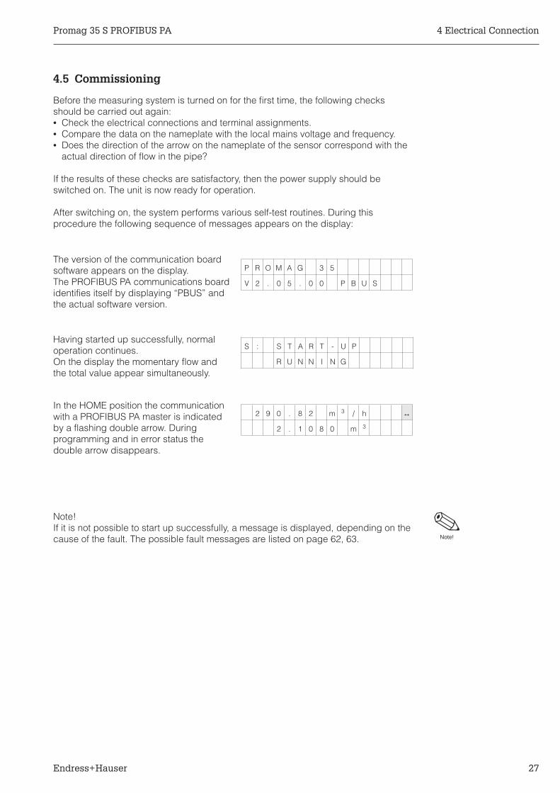
After switching on, the system performs various self-test routines. During thisprocedure the following sequence of messages appears on the display:
The version of the communication boardsoftware appears on the display.The PROFIBUS PA communications boardidentifies itself by displaying “PBUS” andthe actual software version.
Having started up successfully, normaloperation continues.On the display the momentary flow andthe total value appear simultaneously.
In the HOME position the communicationwith a PROFIBUS PA master is indicatedby a flashing double arrow. Duringprogramming and in error status thedouble arrow disappears.
Note!If it is not possible to start up successfully, a message is displayed, depending on thecause of the fault. The possible fault messages are listed on page 62, 63. Note!
P R O M A G 3 5
V 2 . 0 5 . 0 0 P B U S
2 9 0 . 8 2 m 3 / h ↔
2 . 1 0 8 0 m 3
S : S T A R T - U P
R U N N I N G
Promag 35 S PROFIBUS PA 4 Electrical Connection
Endress+Hauser 27

4 Electrical Connection Promag 35 S PROFIBUS PA
28 Endress+Hauser

5 Operation
5.1 Operating and display elements
E - +
ENDRESS+HAUSER
>3s
ba03
5y34
“Enter-key”
3 Access to the programming matrix
Quit the programming matrix, return to the HOME position2 (when E-key is pressed for more than 3 seconds)
Selecting individual functions within the function group,1 saving data or settings
Liquid Crystal Display
• Illuminated, two lines with 16 characters each• Messages and values appear in plain text on the display as well as error, alarm and
status messages• HOME position (display during normal operation of the device):
upper line → factory setting “FLOW RATE”lower line → custom selectable measuring value (factory setting “TOTAL VOLUME”)
+ / – keys
Selecting function groups (>GROUP SELECTION<) or6 programming, e.g. numerical values; setting parameter(When the two keys are held down, the numbers on the display willchange at increasing speed)
Diagnosis and help function7 (simultaneously pushing + and – keys)
3 optical operating elements (“Touch-Control”)
above: infrared transmitting diodebelow: infrared receiving diode
Fig. 27Operating and display elementsPromag 35 S PROFIBUS PA
Promag 35 S PROFIBUS PA 5 Operation
Endress+Hauser 29

5.2 Functions of the operating elements
ENDRESS+HAUSER
E - +
E E E E+
-➁
➂
➃
➀
>3s
E
E
Function groups Functions
Procedure:
1. Access to the programming matrix
2. Select function group (>GROUP SELECTION<)
3. Select function
4. Quit programming matrixReturn to HOME position(from every matrix position, e.g. after programming)
Note!Programming matrix ⇒ see page 31Programming example ⇒ see page 33Description of functions ⇒ see page 35ff.
Note!• When in operating mode, an automatic return to the HOME position will be made if the
operating elements are not actuated for 1 minute (only when the programming islocked).
• If the diagnosis function 7 is activated from the HOME position, an automatic return tothe HOME position will be made if the operating elements are not pressed within 60 se-conds; no matter whether the programming is enabled or locked.
ba03
5y35Fig. 28
Function principle of theoperating elements
Note!
Note!
5 Operation Promag 35 S PROFIBUS PA
30 Endress+Hauser

5.3 Programming matrix Promag 35 S PROFIBUS PA
SY
ST
EM
UN
ITS
Gro
upse
lect
ion
CU
RR
EN
TO
UT
PU
T
FLO
WR
ATE
UN
ITV
OLU
ME
UN
ITG
ALL
ON
S/B
AR
RE
LN
OM
. DIA
M. U
NIT
FU
LLS
CA
LET
IME
CO
NS
TAN
TC
UR
RE
NT
SPA
NFA
ILS
AF
EM
OD
ES
IMU
LAT
ION
CU
RR
.N
OM
INA
LC
UR
RE
NT
DIS
PLA
Y
CO
MM
UN
ICAT
ION
PR
OC
ES
SIN
GPA
RA
ME
TE
R
SY
ST
EM
PAR
AM
ET
ER
SE
NS
OR
DAT
A
TOTA
LV
OLU
ME
TOTA
LO
VE
RF
LOW
RE
SE
TTO
TALI
SE
RF
LOW
RAT
EA
SS
IGN
LIN
E1
AS
SIG
NLI
NE
2D
ISP
LAY
DA
MP
ING
DIS
PLA
YF
OR
MAT
LCD
CO
NT
RA
ST
LAN
GU
AG
E
BU
SA
DD
RE
SS
LOW
FLO
WC
UTO
FF
NO
ISE
SU
PP
RE
SS
:E
MP
TY
PIP
ED
ET.
EP
DR
ES
PO
NS
ET
IME
ME
AS
UR
ING
MO
DE
FLO
WD
IRE
CT
ION
AM
PLI
FIE
RM
OD
ED
ELA
Y
PO
S. Z
ER
OR
ET
UR
ND
EF.
PR
IVAT
EC
OD
EA
CC
ES
SC
OD
ES
ELF
CH
EC
KIN
GP
RE
SE
NT
SY
ST
EM
CO
ND
ITIO
NP
RE
VIO
US
SY
ST
EM
CO
ND
ITIO
NS
OF
TW
AR
EV
ER
SIO
NS
OF
TW
AR
EV
ER
. CO
M
K-F
AC
TOR
PO
S.
K-F
AC
TOR
NE
G.
ZE
RO
PO
INT
NO
MIN
AL
DIA
ME
TE
RM
AX
. SA
MP
LIN
GR
ATE
SA
MP
LIN
GR
ATE
SE
RIA
LN
UM
BE
RE
PD
ELE
CT
RO
DE
CO
ILS
LOP
E
The
se fu
nctio
n is
onl
y sh
ow
nw
ithco
rres
pond
ing
sele
ctio
n/ad
just
men
t
Fie
ld is
pro
tect
ed b
y a
spec
ial c
ode
(ser
vice
cod
e)
ME
AS
UR
ING
PO
INT
SY
ST
EM
CO
NF
IG.
SY
ST
EM
CO
NF
IG.
ba03
5e36
P.36
P.36
P.36
P.37
P.37
P.38
P.38
P.39
P.40
P.40
P.40
P.41
P.41
P.43
P.43
P.43
P.44
P.44
P.45
P.45
P.46
P.50
P.48
P.48
P.49
P.52
P.52
P.52
P.53
P.49
P.53
P.39
P.41
P.41
P.41
P.42
P.42
P.46
P.46
P.47
P.50
P.51
P.51
P.53
P.53
P.54
P.54
Fig. 29Programming matrixPromag 35 S PROFIBUS PA
P.35
Promag 35 S PROFIBUS PA 5 Operation
Endress+Hauser 31

5.4 Information for programming
For the Promag 35 S measuring system, there is a choice of many functions andparameters which the user can set individually and adapt to the process conditions.
Please observe the following important programming notes:• If the power supply breaks down, all calibrated and set values are stored safely
in the EEPROM (without requiring batteries).• Functions which are not required, e.g. current output, can be turned “OFF”. The
corresponding functions in other function groups then no longer appear on thedisplay (see programming matrix on page 31).
• If, during programming, you wish to undo a setting carried out with 6 then select“CANCEL”. This is only possible for settings which have not yet been stored bypressing 1.
• For certain functions, a prompt is given after entering data for safety reasons. Select“SURE? [YES]” with the 6 keys and confirm by pressing 1 again. The setting isthen stored or a function, e.g. zero point calibration, is then activated.
Enable programming (access code)Normally programming is locked. It is therefore impossible to change systemfunctions, numbers or factory settings accidentally. Only after the access code hasbeen entered (factory setting = 35) parameters may be entered or altered.The use of a personal code, which can be chosen freely, prevents data access fromunauthorised personal (see page 48).
Locking programmingFollowing a return in the HOME position, programming is locked after 1 minute withoutactivating an operating element. In addition, programming can be deliberatelylocked by re-entering any code number (other than the customer code) in thefunction “ACCESS CODE”.
5 Operation Promag 35 S PROFIBUS PA
32 Endress+Hauser

5.5 Programming example
You would like to change the bus adress to 25, which is set to default 126 in the factory.Proceed as follows:
E - +>3s
ENDRESS+HAUSERPROMAG
S Y S T E M U N I T S
> G R O U P S E L E C T <
C O M M U N I C A T I O N
> G R O U P S E L E C T <
1 2 6
B U S A D D R E S S
0
A C C E S S C O D E
3 5
A C C E S S C O D E
P R O G R A M M I N G
E N A B L E
1 2 6
B U S A D D R E S S
2 5
B U S A D D R E S S
I N P U T
S A V E D
2 5
B U S A D D R E S S
R E T U R N T O
G R O U P S E L E C T
Entering the programming matrix.3
Selecting the desired function group,6 in this case“COMMUNICATION”
Select the function “BUS ADDRESS”4
On pressing + or - the entry of the6 code is automatically prompted
Enter the code number6 (Factory setting: 35)
1 Programming is now enabled
Select the desired bus adress6 The display stops flashing
New setting: 25
Save the input.1The display flashes and the valuecan be changed again if required.
The programmable value flashes
Return to HOME position2 (press the 1 element for more than
3 seconds). Programming is locked againafter 1 minute, in case no operatingelement is activated.
or
Selecting other functions.1Following the last function anautomatic return to the functiongroup concerned takes place.
Promag 35 S PROFIBUS PA 5 Operation
Endress+Hauser 33

5 Operation Promag 35 S PROFIBUS PA
34 Endress+Hauser

6 Functions
This section is an in-depth description of the individual functions and specifications ofPromag 35 S. Factory settings are indicated in bold italics .With Promag 35 S instruments with customer-specific configuration, values/settingsmay differ from the factory settings shown here.
Function group SYSTEM UNITS → page 35Function group CURRENT OUTPUT → page 37Function group DISPLAY → page 40Function group COMMUNICATION → page 43Function group PROCESSING PARAMETER → page 44Function group SYSTEM PARAMETER → page 48Function group SENSOR DATA → page 52
Function groupSYSTEM UNITS
FLOW RATEUNIT
Selection of the required and indicated units for the flow (volume/time).
The unit selected here is also defining the unit for:• creep rate• full scale value of the current output
Selection:
dm3/s, dm3/min, dm3/h6 m3/s, m3/min, m3/h
l/s, l/min, l/hhl/min, hl/hgal/min, gal/hr, gal/daygpm, gph, gpd, mgdbbl/min, bbl/hr, bbl/daycfs (cubic feet per second)cc/min
Diagnosis:
The actual flow rate appears on the display.7
Promag 35 S PROFIBUS PA 6 Functions
Endress+Hauser 35

Function groupSYSTEM UNITS
VOLUME UNIT Selection of the required and indicated units for the volume flow.
The units selected here are also the same as those for the totaliser value(and totaliser overflow).
Selection:
dm3, m3, l, hl, gal, bbl, 103 gal, ft3
6
Diagnosis:
The actual totaliser value appears on the display.7
GALLONS /BARREL
In the USA and in the UK the relationship between the units barrel (bbl) andgallon (gal) is differently defined, depending on the fluid and the industry. Therelationship required can be selected here. Selection is also made on whetherit is US or imperial gallons.
Note!This function is only available when barrel or gallon is selected as “FLOWRATE UNITS” or “VOLUME UNITS”.
Selection:
US: 31.0 gal/bbl ⇒ for beer6 US: 31.5 gal/bbl ⇒ standard for liquids
US: 42.0 gal/bbl ⇒ petrochemicalsUS: 55.0 gal/bbl ⇒ filling tanksUS: 36.0 gal/bbl ⇒ for beerUS: 42.0 gal/bbl ⇒ petrochemicals
NOM. DIAM.UNIT
This function is used for selecting the required units for nominal diameter.
Note!The units selected here is shown under the function “NOMINAL DIAMETER”(see page 53).
Selection:
mm6 inch
Diagnosis:
The nominal diameter set is shown in the units selected.7
Note!
Note!
6 Functions Promag 35 S PROFIBUS PA
36 Endress+Hauser

Function groupCURRENT OUTPUT
With this group of functions, the user is able to adjust the output current to suit the requirements (fullscale value, time constant, current span, etc.). Two basic modes of the current output are offered.When programming “0/4...20 mA (25 mA)”, the current output can overrun to 125% of the calibratedfull scale value (25 mA), with the programming “0/4...20 mA”, the current output operates according tothe NAMUR recommendations. This allows a maximum full scale overrun of up to 102.5% (20.5 mA).
FULL SCALE By scaling the full scale value, a flow rate is assigned to the 20 mA current.Scaling always applies to both directions of flow (bidirectional), but with theunidirectional mode, only for a positive flow (forward).
Note!When programming according to NAMUR, the range is reduced from 12.5 m/sto 10.25 m/s.
Input:
five-digit number with floating decimal point6 (e.g. 520.00 dm3/min)
Diagnosis:
The units can be selected in the function “FLOW RATE UNIT".7
TIME CONSTANT Selecting the time constant determines whether the current output signalresponds especially rapidly to widely varying flow (short time constant) or isdelayed (long time constant).
The time constant does not affect the behaviour of the display.
Input:
three-digit number with floating decimal point: 0.01...100 s6 Factory setting: 1 s
0 0,3 10 12,5 [m/s]
Minimumfull scale value
20 mA current Maximumfull scale value
Measuring range of Promag 35 electronicsFlow rate Q ~ Fluid velocity v
ba03
5y37
Note!
Promag 35 S PROFIBUS PA 6 Functions
Endress+Hauser 37

Function groupCURRENT OUTPUT
CURRENT SPAN Selecting the 0/4...20 mA current range. This allows a choice between thecurrent output in compliance with NAMUR recommendations (max. 20.5 mA)or the current output with a maximum of 25 mA.
Selection:
0...20 mA current output according to NAMUR6 4...20 mA current output according to NAMUR
0...20 mA (25 mA) maximum 25 mA4...20 mA (25 mA) maximum 25 mA
FAILSAFEMODE
For safety reasons, in the event of a fault it is useful for the current output toassume a previously defined status.
The setting only affects the current output.
Selection:
MIN. CURRENT6 When a fault occurs, the current signal is set to 0 mA
(0...20 mA) or 2 mA (4...20 mA).
MAX. CURRENTThe current signal is set to 25 mA for 0/4...20 mA (25 mA) or22 mA for 0/4 ...20 mA.
HOLD VALUELast valid measured value is held.
ACTUAL VALUENormal measured output despite fault.
25
20
20,5
4 ... 20 mA
0 ... 20 mA
I [mA]
NAMUR
Q
Scaled fullscale value
Scaled fullscale value
Reverseflow
-Q
Forwardflow
ba03
5y38
[Volume/time]
6 Functions Promag 35 S PROFIBUS PA
38 Endress+Hauser
Function groupCURRENT OUTPUT
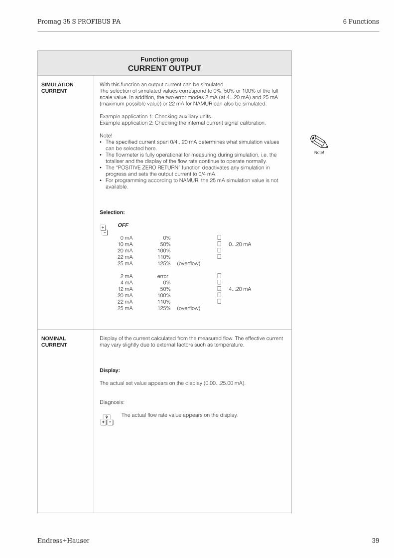
SIMULATIONCURRENT
With this function an output current can be simulated.The selection of simulated values correspond to 0%, 50% or 100% of the fullscale value. In addition, the two error modes 2 mA (at 4...20 mA) and 25 mA(maximum possible value) or 22 mA for NAMUR can also be simulated.
Example application 1: Checking auxiliary units.Example application 2: Checking the internal current signal calibration.
Note!• The specified current span 0/4...20 mA determines what simulation values
can be selected here.• The flowmeter is fully operational for measuring during simulation, i.e. the
totaliser and the display of the flow rate continue to operate normally.• The “POSITIVE ZERO RETURN” function deactivates any simulation in
progress and sets the output current to 0/4 mA.• For programming according to NAMUR, the 25 mA simulation value is not
available.
Selection:
OFF6
0 mA 0% 10 mA 50% 0...20 mA20 mA 100% 22 mA 110% 25 mA 125% (overflow)
2 mA error 4 mA 0%
12 mA 50% 4...20 mA20 mA 100% 22 mA 110% 25 mA 125% (overflow)
NOMINALCURRENT
Display of the current calculated from the measured flow. The effective currentmay vary slightly due to external factors such as temperature.
Display:
The actual set value appears on the display (0.00...25.00 mA).
Diagnosis:
The actual flow rate value appears on the display.7
Note!
Promag 35 S PROFIBUS PA 6 Functions
Endress+Hauser 39

Function groupDISPLAY
TOTALVOLUME
Here, the summed flow quantity is shown as a floating-point numberof maximum seven digits.
Display:Max. seven-digit number (0.0000....9999999)Factory setting: 0.0000
Diagnosis:
The units can be selected in the function “VOLUME UNIT”7 (see page 36).
TOTALOVERFLOW
The total flow quantity is displayed in the HOME position by a max. seven-digitnumber with variable decimal point. Larger numbers (>9,999,999) are shownin this function as overflow. The effective quantity is thus the sum of theoverflow and the value shown in the HOME position (or in the function “TOTALVOLUME”).
Example:The display shows 2e7 dm3 ⇒ overflow = 2 x 10⁷ dm3 = 20,000,000 dm3.The actual totaliser value is 196,845.7 dm3. The total amount, added togethersince measurement started, is therefore 20,196,845.7 dm3.
Note!• This display only appears when there is an overflow. In addition, in the HOME
position an overflow is made visible by optically inverting the “>”sign.• With bidirectional measurement, the totaliser value may have a positive or a
negative sign.
Display:Integer to a decimal point (e.g. 10e7 dm3)
Diagnosis:
The actual totaliser value (HOME position) appears on the display.7
RESETTOTALISER
The totaliser can be reset to zero.
Note!Not only the “overflow” but also the value displayed in the HOME positionis reset to zero.
Selection (with prompt):
NO6 YES
Diagnosis:
The actual totaliser value appears on the display.7
Note!
Note!
6 Functions Promag 35 S PROFIBUS PA
40 Endress+Hauser

Function groupDISPLAY
FLOW RATE Here, the current flow value is shown. This is particularly advantageous if theHOME position is assigned to other measured variables.
Display:
Max. five-digit number (-99999...+99999). Unit according to the selection inthe function “FLOW RATE UNIT”.
ASSIGN LINE 1 With this function the variable is defined which is to be displayed on the upperdisplay line during normal operation (HOME position).
Selection:
FLOW RATE - TOTAL VOLUME6
ASSIGN LINE 2 With this function the variable is defined which is to be displayed on the lowerdisplay line during normal operation (HOME position).
Selection:
OFF - FLOW RATE - TOTAL VOLUME - TOTAL OVERFLOW6
DISPLAYDAMPING
Selecting a time constant determines whether the display reacts quickly (smalltime constant) or slowly (large time constant) to changing flow values.
Note!• Damping is inactivated when set to “zero”.• The damping of the display does not affect the behaviour of the current
output.
Input:
Max. two-digit number: 0...99 seconds6 Factory setting: 1 s
DISPLAY FORMAT The number of significant digits for displaying the actual flow rate is selected.Along with the function “DISPLAY DAMPING”, this serves to stabilise heavilyfluctuating flows.
Note!• Insignificant digits in front of the decimal point are shown as zeros.• Insignificant digits after the decimal points are not shown, and the last digit
displayed is rounded.
Selection:
X.XXXX (five significant digits)6 X.XXX (four significant digits)
X.XX (three significant digits)
Note!
Note!
Promag 35 S PROFIBUS PA 6 Functions
Endress+Hauser 41

Function groupDISPLAY
LCD CONTRAST The contrast can be adjusted optimally to match the operating conditions onsite.
Caution!At temperatures below the freezing point (<0 °C) the visibility of the displaytext is no longer assured, even with maximum contrast. If no display is visible,then see page 60.
Adjustment:
A change in contrast is immediately indicated with a6 bar graph (IIIIIIIII.......).
LANGUAGE Selection of the operating language required.
Selection:
ENGLISH6 DEUTSCH
FRANCAISESPANOLITALIANONEDERLANDSDANSKNORSKSVENSKASUOMIBAHASA INDONESIAJAPANESE
Factory setting: country-specific
Note!By simultaneously pressing the 6 keys during power-up the Promag 35 startswith “ENGLISH” and maximum contrast.Note!
Caution!
6 Functions Promag 35 S PROFIBUS PA
42 Endress+Hauser

Function groupCOMMUNICATION
BUS ADDRESS In this function the bus address is set.
Local configuration can be deactivated using a miniature switch (DIP switch)on the communications board. When this is done, “DIP switch” is displayed(see page 57).
Input:
three-digit number: 0...1276 Factory setting: 126
Diagnosis:
In case the DIP switch addressing mode is selected, the choosen7 address is displayed.
MEASURINGPOINTDESIGNATION
In this function, the actual measuring point designation (name) is displayed.It is set by the PROFIBUS master, e.g. Commuwin II.
The measuring point designation corresponds to the TAG-DESC of thePhysical Block, as defined in the PROFIBUS PA profile B.
Diagnosis:
The complete measuring point designation is displayed7 (up to 32 characters).
SYSTEMCONFIG.
This function enables switching between local operation (via E+H matrix) andremote operation via PROFIBUS PA.
The device can only be operated in either local or remote mode at one time.The system configuration and parameters are independent of the operationmode and are carried out in the event of a change of the operating mode.
Display:
LOCAL - REMOTE6
Promag 35 S PROFIBUS PA 6 Functions
Endress+Hauser 43

Function groupPROCESSING PARAMETER
LOW FLOWCUTOFF
Set the required switch point for the creep rate (volume/time). Creepsuppression prevents a rate of flow being measured in the lower part of therange (e.g. fluctuating head at standstill). The creep function always operateswith negative hysteresis:
Note!• When creep suppression is active, the sign of the flow appears optically
inverted on the display.• The max. creep rate depends on the nominal diameter of the sensor currently
being used and corresponds to a flow velocity v = 1 m/s.• The units shown can be selected in the function “FLOW RATE UNIT”.
Input:
five-digit number with floating decimal point6 (e.g. 15,000 dm3/min.)
Diagnosis:
Hysteresis = 50%7 Creep suppression operates with a negative hysteresis of 50%.
NOISESUPPRESS.
A software filter (= interference blanking) can be used to reduce the sensitivityof the output signals to transient flows and interference peaks, e.g. with fluidscontaining solids.
Selection:
OFF6 LOW
MEDIUMHIGH
1
2
1
2
Flow rate[Volume/time]
Hysteresis = -50% of creep rate1 Suppression switched on2 Suppression switched off
time
ba03
5y39
suppression suppressionactivated activated
Creeprate
Creep rate100%
50%
Note!
6 Functions Promag 35 S PROFIBUS PA
44 Endress+Hauser

Function groupPROCESSING PARAMETER
EMPTY PIPEDET.
Only a completely full flowmeter pipe enables correct readings to be obtained.This can be continuously checked by Empty Pipe Detection(= EPD). EPD is based on measuring the conductivity of the fluid. Ifconductivity drops below a specific value defined by EPD, then the displayshows the error message “EMPTY PIPE”. The alarm effects also the otheroutputs according to their settings.
Note!• The EPD function is available only if the sensor is fitted with an extra
electrode.• Before switching on EPD, the full/empty adjustment necessary for EPD must
be carried out within this function.• If the alarm message “EMPTY PIPE” appears, though the pipes are filled, a
new full/empty adjustment must be carried out.• If different fluids with different conductivity are measured, a new full/empty
adjustment must be made for each fluid!• EPD can be switched on and off by software at any time.• EPD has the same effect on the outputs as if there was a fault.
Selection:
OFF - ON - EMPTY PIPE ADJ. - FULL PIPE ADJ.6
EPD RESPONSETIME
The response time of Empty Pipe Detection can be selected by the user to suitprocess conditions. An alarm is not given until this response time has expired.Brief air bubbles in the flowmeter are then not interpreted as a partly filled pipe.
This function is only available when Empty Pipe Detection is switched “ON”.
Selection:
60 s6 30 s
10 s5 s2 s1 s
Measurand 1
Switchingpoint (EPD)
Measurand 2
Empty pipe
Full pipe
Conductivity[µS/cm]
ba03
5y40
Note!
1/2 • (Measurand 1+2)
Promag 35 S PROFIBUS PA 6 Functions
Endress+Hauser 45

Function groupPROCESSING PARAMETER
MEASURINGMODE
The measuring system is able to measure in both flow directions(bidirectional). The signal outputs (PROFIBUS PA interface, current output,and the internal totaliser) can all be switched to a unidirectional mode. In thiscase, a signal is only given or internally totalised for positive flow. The flowdisplay in the HOME position still operates in both flow directions.
Selection:
UNIDIRECTIONAL6 BIDIRECTIONAL
FLOWDIRECTION
There is an arrow on the flowmeter nameplate to indicate the positive (forward)flow direction. Under certain circumstances it may be necessary to operatethe flowmeter in the reverse direction. This can be done by inverting the signof the flow rate measured (reverse).
Selection:
FORWARD1)
6 REVERSE2)
1) Positive flow according to the arrow on the nameplate.2) Positive flow opposite the direction of the arrow on the nameplate.
AMPLIFIERMODE
The Promag 35 amplifier has an automatic amplifier gain control. This ensuresthat the amplifier always operates at optimum amplification according to theflow velocity of the fluid. High accuracy is thus maintained over a widedynamic range of 1000:1.Applications with rapid and heavily fluctuating flow rates can still affect themeasurement and the desired accuracy will not be achieved. In suchapplications it may be better under certain circumstances to program theamplifier at a fixed amplification step.
Caution!With selection of “MODE 3” or “MODE 4”, it must be ensured that the actualflow velocity is not higher than the selected velocity range. Overshooting willnot be registered as an error and can lead to false measurements.
Selection:
NORMAL automatic amplifier gain control6 MODE 1 for flow rates 0...>12 m/s
MODE 2 for flow rates 0...12 m/sMODE 3 for flow rates 0...4 m/sMODE 4 for flow rates 0...1 m/s
Caution!
6 Functions Promag 35 S PROFIBUS PA
46 Endress+Hauser

Function groupPROCESSING PARAMETER
DELAY Within the measuring amplifier, the delay of the automatic amplificationswitchover may be varied. In case of an overload, the amplification isimmediately reduced, independent of the value set originally. In case of amassive underload, the ‘n’ measured results (samples) are waited for beforethe amplification is once again increased.
This is especially useful if occasional and rapid flow peaks occur (e.g. pistonpumps). The programmed number thus corresponds to the number ofmeasuring events (samples) to be ignored before a switch-over of theamplifier gain control is necessary.
Selection:
Max. four-digit number: 10...10006
Promag 35 S PROFIBUS PA 6 Functions
Endress+Hauser 47

Function groupSYSTEM PARAMETER
POS. ZERORETURN
With positive zero return (PZR) the output signals can be deliberately set tozero. Measured value suppression is equivalent to zero flow:
• PROFIBUS PA interface: flow = 0• Current output signal ⇒ 0/4 mA• Display of HOME position: flow = 0; totaliser remains at the actual value
Caution!This function has top priority over all other functions of the instrument.Simulation in progress is interrupted by the PZR.
Selection:
OFF6 ON
DEF. PRIVATECODE
Selection of a personal code number, to enable programming.For the Promag 35 S measuring system the factory setting is 35.
• When programming is locked, this function is not available and access to thepersonal code by third parties is excluded.
• The code number can only be altered when programming has been enabled.
Caution!Programming is always enabled when code number = 0 is selected.
Input:
Max. four-digit number: 0...99996 Factory setting: 35
Caution!
Caution!
6 Functions Promag 35 S PROFIBUS PA
48 Endress+Hauser

Function groupSYSTEM PARAMETER
ACCESS CODE All data of the Promag 35 S measuring system are protected againstunauthorised access. By entering a code number, programming is enabledand the settings of the instrument can be altered:• Entering code set in the factory “35"• Entering personal code number
Note!• If, in any function, the + or - key is pressed when programming is locked,
a call to enter the code number is automatically issued. Once this numberhas been entered, programming is enabled.
• Following a return to the HOME position, programming is again locked after1 minute if no key is pressed during this time.
• Programming can also be locked by entering another code number in thefunction ”ACCESS CODE" (not the same number as the personal code).
• A set of functions can only be altered once a special code (servicecode) has been entered as changing these parameters would lead toinaccuracies in measurement. This code is known by your E+H Serviceorganisation.For more information, please contact your E+H Service organisation.
Caution!If you can no longer find your personal code, the Endress+Hauser Serviceorganisation will be able to help you.
Input:
Max. four-digit number: 0...99996
SELFCHECKING
Switching the periodical self check of the amplifier on or off. The amplifier isfitted with an automatic temperature compensation. Any temperature driftoccurring in the region of the amplifier path can be compensated for by aperiodical measurement against an internal reference voltage.
Selection:
OFF6 ON
Caution!
Note!
Promag 35 S PROFIBUS PA 6 Functions
Endress+Hauser 49

Function groupSYSTEM PARAMETERS
PRESENTSYSTEMCONDITION
System and process errors, as well as status messages which occur whilemeasurement is in progress, are displayed in the HOME position, alternatingwith the measured values. A jump to the diagnostic function is madeautomatically by pressing the diagnostic key. The user can scan the error andstatus messages currently on hand.
Note!• The messages are displayed in order of message importance
(first message = highest priority)• A complete list of all possible error and status messages can be found
on page 62f.• With error-free measurement the message “S: SYSTEM WORKS NORMALLY”
appears.• This function can also be selected directly through the function group
“SYSTEM PARAMETERS”.
Procedure (example):
In the HOME position, press the diagnostic function key7 (or select this function via the programming matrix).
With the diagnostic function, additional error descriptions7 can be scanned (with system errors only!)
Ask for further error or status messages.6
PREVIOUSSYSTEMCONDITIONS
In this function all error and status messages that have occurred are listed inchronological order (max. 10 messages).
Note!• Storage of this list is volatile and is lost if the power supply is interrupted.• A complete list of all possible error and status messages can be found on
page 62f.• If no error or status messages have occurred since the measuring equipment
was last started up, then the message “S: NO ENTRY EXISTING” will appear.
Selection:
Other system/process parameters and status messages are called up:6 ”+” lists chronologically the oldest, second oldest ... etc. message
”–” lists the most recent, second most recent ... etc. message.
F : S Y S T E M E R R O R
P O W E R S U P P L Y
9 : L O W V O L T A G E
D E T E C T E D
(Example)
Note!
Note!
6 Functions Promag 35 S PROFIBUS PA
50 Endress+Hauser

Function groupSYSTEM PARAMETER
SOFTWAREVERSION
Display of the software version installed on the amplifier board.The numbers of the software version have the following meaning:
PRO 35 V 3 . 01 . 00
Number changes if basic alterations haveto be made to the software, e.g. due totechnical modifications to the flowmeter.
Number changes if the new softwarecontains additional functions.
Number changes if minor alterations aremade to the new software.Also for special releases of software.
SOFTWAREVER. COM
Display of the software version installed on the communication board.The numbers of the software version have the following meaning:
V 2 . 05 . 00 PBUS
Number changes if basic alterations haveto be made to the software, e.g. due totechnical modifications to the flowmeter.
Number changes if the new softwarecontains additional functions.
Number changes if minor alterations aremade to the new software.Also for special releases of software.
Communication interface
Note!If the display does not show “PBUS”, no PROFIBUS PA communications boardis installed, but another type!
Note!
Promag 35 S PROFIBUS PA 6 Functions
Endress+Hauser 51

Function groupSENSOR DATA
Sensor data, such as nominal diameter, calibration factor, etc., are set in the factory. All characteristicvalues of the sensor are stored in the DAT memory. The functions of this line can only be saved afterentering a special code (service code) and cannot be altered using the personal code. Pleasecontact your E+H Service organisation for more information.
Caution!Normally these characteristic data should not be altered. A change to the data of the sensor affects anumber of functions of the whole measuring system, especially its accuracy.
K-FACTOR POS. The calibration for the positive direction of flow depends on the particularsensor. The factor is determined and set in the factory.
Caution!Normally the calibration factor should not be altered. The special code(service code) is known to your E+H Service organisation.Please contact it for more information.
Selection:
five-digit number with fixed decimal point (0.5000...2.0000)6 Factory setting: dependent on the sensor: nominal diameter and
its calibration
K-FACTOR NEG. The calibration for the negative direction of flow depends on the particularsensor. The factor is determined and set in the factory.
Caution!Normally the calibration factor should not be altered. The special code(service code) is known to your E+H Service organisation.Please contact it for more information.
Selection:
five-digit number with fixed decimal point (0.5000...2.0000)6 Factory setting: dependent on the sensor: nominal diameter and
its calibration
ZERO POINT(OFFSET)
The zero point error depends on the particular sensor. It is determined and setin the factory.
Caution!Normally the calibration factor should not be altered. The special code(service code) is known to your E+H Service organisation.Please contact it for more information.
Selection:
Max. four-digit number (-1000...+1000)6 Factory setting: dependent on the sensor: nominal diameter and
its calibration
Caution!
Caution!
Caution!
Caution!
6 Functions Promag 35 S PROFIBUS PA
52 Endress+Hauser
Function groupSENSOR DATA
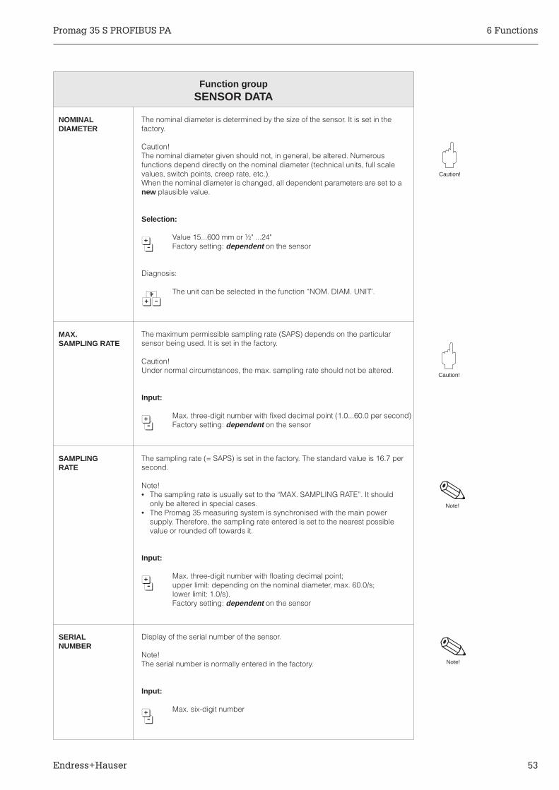
NOMINALDIAMETER
The nominal diameter is determined by the size of the sensor. It is set in thefactory.
Caution!The nominal diameter given should not, in general, be altered. Numerousfunctions depend directly on the nominal diameter (technical units, full scalevalues, switch points, creep rate, etc.).When the nominal diameter is changed, all dependent parameters are set to anew plausible value.
Selection:
Value 15...600 mm or ½" ...24"6 Factory setting: dependent on the sensor
Diagnosis:
The unit can be selected in the function “NOM. DIAM. UNIT”.7
MAX.SAMPLING RATE
The maximum permissible sampling rate (SAPS) depends on the particularsensor being used. It is set in the factory.
Caution!Under normal circumstances, the max. sampling rate should not be altered.
Input:
Max. three-digit number with fixed decimal point (1.0...60.0 per second)6 Factory setting: dependent on the sensor
SAMPLINGRATE
The sampling rate (= SAPS) is set in the factory. The standard value is 16.7 persecond.
Note!• The sampling rate is usually set to the “MAX. SAMPLING RATE”. It should
only be altered in special cases.• The Promag 35 measuring system is synchronised with the main power
supply. Therefore, the sampling rate entered is set to the nearest possiblevalue or rounded off towards it.
Input:
Max. three-digit number with floating decimal point;6 upper limit: depending on the nominal diameter, max. 60.0/s;
lower limit: 1.0/s).Factory setting: dependent on the sensor
SERIALNUMBER
Display of the serial number of the sensor.
Note!The serial number is normally entered in the factory.
Input:
Max. six-digit number6
Caution!
Caution!
Note!
Note!
Promag 35 S PROFIBUS PA 6 Functions
Endress+Hauser 53

Function groupSENSOR DATA
EPDELECTRODE
This function indicates whether the sensor is equipped with an electrode forEmpty Pipe Detection (EPD). This setting is made in the factory to suit thesensor installed.
Note!Empty Pipe Detection can only be activated when an EPD electrode is fitted.
Selection:
YES6 NO
Factory setting with standard EPD electrodes: “YES”
COIL SLOPE To optimize the field coil slope, the coil voltage is briefly exalted. The durationof this period of exalted voltage varies according to the diameter and is set atthe factory.
Caution!The value set at the factory may only be altered after consulting your E+HService Organisation. This function is protected by a service code.
Selection:
Max. three-digit number (0...255)6
Caution!
Note!
6 Functions Promag 35 S PROFIBUS PA
54 Endress+Hauser

7 PROFIBUS PA Interface
7.1 PROFIBUS PA
Note!Refer to Technical Information Manual TI 260F/00/en “Field Communications-PlanningNotes PROFIBUS PA” for detailed project information about PROFIBUS PA.
7.2 GSD- and Type-Files
To integrate PROFIBUS PA devices in a control system, GSD and type files arerequired.
A floppy disk is shipped with each order. The files on this disk have to be loaded inthe control system (e.g. COMET 200 or COM PROFIBUS) prior start-up of a field bussystem.
This files are stored as follows:• all *.200-files in the directory of the type-files ... \TYPDAT5X• all *.GSD-files in the directory of the GSD-files ... \GSD• all *.BMP-files in the directory of the bitmaps ... \BITMAPS
The meaning of this parameters is defined in the PROFIBUS PA specification.
The floppy disk is supplied with the delivery and may also be ordered fromE+H Flowtec AG (Order No. 50087303).
Note!
PLC
31.25 kbit/s
Process control system
Commuwin II
IEC 1158
ba03
5e41
Fig. 30PROFIBUS PA
Promag 35 S PROFIBUS PA 7 PROFIBUS PA Interface
Endress+Hauser 55

7.3 Setting the bus address
The address of a PROFIBUS PA device is an obligatory setting. An incorrect settingof the address will result in the fieldbus not recognising the device. Valid deviceaddresses range from 0...127.
All devices are delivered with the default address 126. This address can be used fortesting the device. This address must be changed before installing the device into aPROFIBUS PA network. The address is a unique identifier and must only be usedonce in a PROFIBUS network.The configuration of a PROFIBUS PA device address for a Promag 35 can be doneeither through local operation or by using the DIP switches on the communicationsboard (see page 57).
7.4 PROFIBUS PA addressing via touch control
See page 43Device function → Group function “COMMUNICATION” → Function “BUS ADDRESS”.
7 PROFIBUS PA Interface Promag 35 S PROFIBUS PA
56 Endress+Hauser
7.5 Addressing PROFIBUS PA by DIP switches
With DIP switch No. 8 the address mode is selected. The addressing is done bylocal operation (touch control), when the DIP switch No. 8 is set to “OFF”. Addressingis done by the DIP switches 1...7 (see Fig. 31), when DIP switch No. 8 is set to “ON”.
Note!Factory setting is DIP switch No. 8 = OFF (local operation). Note!
Procedure:
Warning!Danger from electrical shock! Switch off the power supply before opening the electronics housing.
1. Loosen the screw of the safety claw (3 mm Allen key).2. Unscrew the cover of the transmitter electronics compartment.3. Remove the local display (if present), by loosening the mounting screws of the display module.4. Set the DIP switches on the communications board using an appropriate object.5. Reassemble in reverse sequence.
Switch number
1
2
3
4
5
6
7
8
9
10
11
12
1
2
4
8
16
32
64
Bus address (diagram: 1+16+32 = 49)
Address mode: (OFF = local operation)(ON = DIP switches)
no function
ba03
5y42
OFF ONSelector switches
➁➂
➃
➀
Fig. 31Addressing with the DIPswitches on thecommunications board
Warning!
Promag 35 S PROFIBUS PA 7 PROFIBUS PA Interface
Endress+Hauser 57

7.6 PROFIBUS PA Parameters
The function block model of the Promag 35
The Promag 35 software contains the following function blocks:
• One AI block (AI = Analogue Input)The universal AI block supplies all flow rate parameters to the control system.
Three specialised function blocks related to flow measurement are implemented inaccordance with the recommendation of the PROFIBUS PA profile definition.
• One Totaliser function blockThe totaliser block allows direct access to the Promag 35 from the control system.
• One Transducer block for flow rateThe transducer block contains the sensor data, e.g. the calibration factor.
• One Physical blockThe physical block contains information such as language, measuring pointdesignation or the contrast of the LC display etc.
In addition, the control system is able to control important parameters of these blockssuch as the time constant of the flow or type of functions, e.g. reset of the totaliser.
TDTransducerBlock
PBPhysicalBlock
AIFunctionBlock
TotalizerFunctionBlock
ENDRESS+HAUSERPROMAG33
Promag 35
PROFIBUS PAba
035y
43
Fig. 32Function block model of thePromag 35 PROFIBUS PA
7 PROFIBUS PA Interface Promag 35 S PROFIBUS PA
58 Endress+Hauser

8 Troubleshooting and Remedies
8.1 Response of the measuring system to faults or alarm
Error messages which occur while measuring is in progress are displayed in theHOME position alternately to the measured values. The Promag 35 S measuringsystem distinguishes between two kinds of error:
Caution!Note the following points when measured value suppression or simulation is active:
Measured value suppression• This function has top priority. The appropriate status message “S: POSITIVE ZERO
RETURN ACTIVE” is also displayed with priority in the HOME position. Any errormessages which occur during this time can only be asked for and displayed withthe aid of the diagnostic function.
• Measured value suppression sets all signal outputs to zero (corresponding to zeroflow).
Simulation• This function has second highest priority, likewise the corresponding status
message. Any error messages which occur during this time can only be askedfor and displayed with the aid of the diagnostic function.
Caution!
Type of error Response of the measuring instrument
Fault(system error)
Fault due to failure of the instrument → Corresponding message on the display
→ The signal outputs respond according to theirerror settings.
Alarm(process error)
Fault due to factors influencing the process → Corresponding message on the display
Promag 35 S PROFIBUS PA 8 Troubleshooting and Remedies
Endress+Hauser 59

8.2 Instructions for troubleshooting
During manufacture, all units undergo quality control at numerous stages. The last ofthese stages is wet calibration, carried out on a calibration rig conforming to the lateststate of the art technology.
To help you locate faults, some of their possible causes are given here.
Is the supply voltage present atterminals 1 and 2? NO
• Check the wiring against the wiringdiagrams.
• Check the distribution fuse.
YES
Is the fuse in the terminal compartment sound? NO Replace blown fuse.
YES
Is the display visible?
Caution!Visibility of the LCD is no longer assured attemperatures <0 °C.
NO
1. Switch off the supply voltage.2. Reapply the supply voltage at the same
time actuating the 6 operating elements.The measuring system starts with maximumpossible contrast.
YES
Does one of the following status messagesappear on the display?S: POSITIVE ZERO RETURN ACTIVES: CURRENT OUTPUT SIMULATION ACTIVE
YESSwitch off the function concerned.
NO
Does an error message appear on the display?NO
No system or process error has occured:• Check the wiring of the output signal cable.• Check parameters.
YES
Is a system error concerned?(Fault, Failure)?F:..............
YES• With the diagnostic function 6 ask for more
details of the fault.• Take measures to clear the fault
(see page 62).
NO
Is a process error involved(Alarm)?A: ..............
YESTake measures to clear the fault(see page 63).
NO
Does a status message appear on the display?S:................
YES Note status messages (see page 63).No action required.
8 Troubleshooting and Remedies Promag 35 S PROFIBUS PA
60 Endress+Hauser
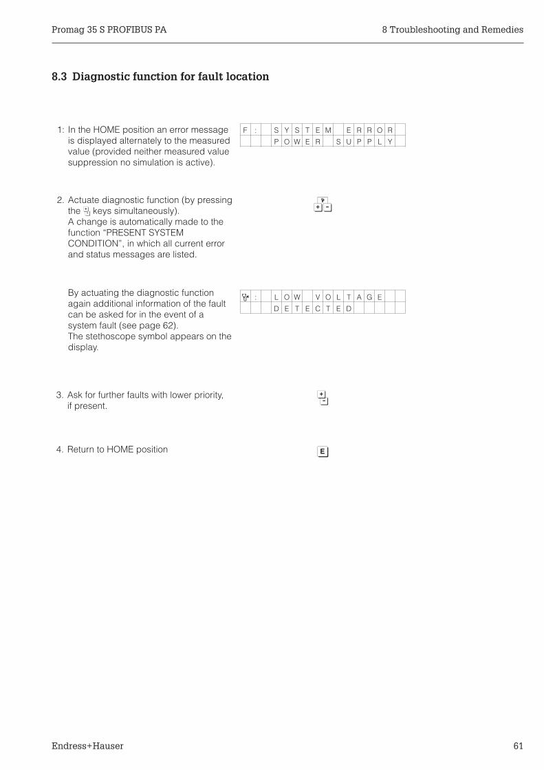
8.3 Diagnostic function for fault location
F : S Y S T E M E R R O R
P O W E R S U P P L Y
7
9 : L O W V O L T A G E
D E T E C T E D
6
1
1: In the HOME position an error messageis displayed alternately to the measuredvalue (provided neither measured valuesuppression no simulation is active).
2. Actuate diagnostic function (by pressingthe 6 keys simultaneously).A change is automatically made to thefunction “PRESENT SYSTEMCONDITION”, in which all current errorand status messages are listed.
By actuating the diagnostic functionagain additional information of the faultcan be asked for in the event of asystem fault (see page 62).The stethoscope symbol appears on thedisplay.
3. Ask for further faults with lower priority,if present.
4. Return to HOME position
Promag 35 S PROFIBUS PA 8 Troubleshooting and Remedies
Endress+Hauser 61

8.4 Error and status messages
Diagnosiscode
Error messages F:....(system error, failure)
Cause(call up by 7)
Remedy
4
5
F: SYSTEM ERRORPOWER SUPPLY
9: LOW VOLTAGEDETECTEDThe voltage from the power supply boardis too low.
9: COIL CURRENT CONTROLCoil current out of tolerance.
By E+HService
By E+HService
7
6
8
9
10
F: SYSTEM ERRORAMPLIFIER
9: EEPROM FAILUREError when accessing EEPROM data (adjustedvalues of the amplifier)
9: DAT FAILUREError when accessing DAT data (adjusted valueof sensor).
9: ROM / RAM FAILUREError when accessing program memory (ROM)or main memory (RAM) of the processor.
9: GAIN ERRORAMPLIFIERGain error of the amplifier.
9: NO AMPLIFIER RESPONSEFaulty data transmission betweencommunication module and amplifier.
By E+H Service
Call your E+HService
By E+HService
By E+HService
By E+HService
17 F: VALUE NOTACCEPTED
The value entered was not correctly accepted bythe amplifier.
Repeat input
11
12
13
14
15
16
F: SYSTEM ERRORCOM-MODULE
9: MODULE NOTCOMPATIBLECommunication module and amplifier are notcompatible
9: EEPROM FAILUREError when accessing EEPROM data (processand adjustment data of the communicationmodule).
9: RAM ERRORError when accessing the main memory(RAM).
9: ROM ERRORError when accessing the program memory(ROM).
9: LOW VOLTAGEDETECTEDThe voltage supplied by the DC/DC converteron the communication module is too low.
9: VOLTAGEREFERENCEVoltage reference of the communication moduleis out of tolerance, i.e. correct functioning of thecurrent output is not assured.
By E+HService
By E+HService
By E+HService
By E+HService
By E+HService
By E+HService
8 Troubleshooting and Remedies Promag 35 S PROFIBUS PA
62 Endress+Hauser

Diagnosiscode
Alarm messages A:....(process errors)
Cause Remedy
18 A: EPD ADJUSTMENTVALUES MISSING
EPD switched on. No adjustment has taken place. Adjust EPD asdescriped onpage 45.
20 A: EPD ADJUSTMENTFULL = EMPTY
EPD switched on, but alarm given becauseadjustment values for full and empty pipe areidentical.
Repeatadjustment asdescriped onpage 45.
21 A: EPD ADJUSTMENTFULL <=> EMPTY
EPD switched on, but alarm given becauseadjustment did not take place with full or emptypipe.
Repeatadjustment asdescriped onpage 45.
19 A: EPD ADJUSTMENTNOT POSSIBLE
EPD switched on, adjustment not possiblebecause the conductivity of the medium is outsidethe permissible range (too high or too low).
EPD functioncannot be used.
22 A: EMPTY PIPEDETECTED
The measuring pipe is notcompletely full or may be empty.
Check theprocessconditions of theinstallation.
23 A: FLOWTOO HIGH
Fluid velocity in flowmeter >12.5 m/s.Measuring range of transmitter electronicsexceeded.
Reduce flow rate.
24 A: CURRENT OUTP.TOO HIGH
The actual flow rate is too high for the scaled fullscale value (Imax = 25 mA).
Scale a higherfull scale value(see page 37) orreduce flow rate.
Diagnosiscode
Status messages S:.... Cause Remedy
1 S: POS. ZERORET. ACTIVE
Measured value suppression active. Thismessage has top priority for Promag 35.
Unnecessary
2 S: CURRENT OUTP.SIMUL. ACTIVE
Current simulation active. Unnecessary
27 S: EPD ADJUSTMENTRUNNING
EPD adjustment in progress (full or empty pipeadjustment).
Unnecessary
Promag 35 S PROFIBUS PA 8 Troubleshooting and Remedies
Endress+Hauser 63

8.5 Replacing the fuse
Warning!Danger from electrical shock! Switch off the power supply before unscrewing thecover of the terminal compartment from the transmitter housing.
Use only the following types of fuses:
8.6 Repairs
If a Promag 35 S flowmeter is to be sent to Endress+Hauser for repair, then it mustalways be accompanied by a note containing the following information:• Description of the application• Description of the fault• Description of the chemical and physical properties of the product being measured.
Caution!The following procedures must be carried out before a Promag 35 S flowmeter is sentfor repair:• Remove all residue which may be present.
This is especially important if the fluid is dangerous to health, e.g. corrosive,poisonous, carcinogenic, radioactive, etc.
• No instrument should be returned to us without first completely removing alldangerous material (e.g. penetrated into scratches or diffused though plastic parts).
Incomplete cleaning of the instrument may result in waste disposal or cause harm topersonnel (burns, etc). Any costs arising from this will be charged to the owner of theinstrument.
Warning!
Caution!
Approval Voltage Location Dimensions Nominal current/Nominal voltage
Typ
Non Ex 180...260 V AC Supplyboard
5.2 x 20 mm 1 A / 250 V slow blow
CSA General PurposeNon Ex
85...130 V AC Supplyboard
5.2 x 20 mm 1 A / 250 V slow blow
Non Ex 24 V AC/DC Supplyboard
5.2 x 20 mm 1 A / 250 V slow blow
8 Troubleshooting and Remedies Promag 35 S PROFIBUS PA
64 Endress+Hauser

9 Dimensions and Weights
DN 15...200
Weights Transmitter:Compact version 3 kgRemote version 5 kg (with wall mounted)
190.
5
171
K
A
B C
B1156.5
FH
209
(185)
Compact version
ba03
5y44
Fig. 33Promag 35 SCompact versionDN 15...200
ANSCHLUSSKLEMMEN - FIELD TERMINALS
ANSCHLUSSKLEMMEN - FIELD TERMINALS
246
(222)
100
25Ø 8
.6 (
M8)
133
334
177.
515
6.5
100
123
130
L
E
86
Remote version (FS)
ba03
5y45
Fig. 34Promag 35 SRemote versionDN 15...200
DN PN1) L A B C K E F H B1 Weight
[mm] [inch]DIN[bar]
ANSIClass
JIS DIN/ANSI[mm]
JIS[mm] [mm] [mm] [mm] [mm]
PTFE[mm]
HG/WG[mm]
DIN[mm]
ANSI[mm]
JIS[mm] [mm] [mm] [kg]
15 1/2" 40 150 – 156/152 – 361 291.5 69.5 200 94.2 – 14 12 – 194.5 125 6
25 1" 16 150 20K 202 228 409 315.5 93.5 247.6 121.2 120 14 15 20 242.5 149 8
32 – 16 150 20K 202 228 409 315.5 93.5 247.6 121.2 120 16 16 20 242.5 149 10
40 11/2" 16 150 20K 202 228 409 315.5 93.5 247.6 121.4 120 16 18 20 242.5 149 11
50 2" 16 150 10K 202 202 409 315.5 93.5 247.6 121.8 120 18 20 18 242.5 149 12
65 – 16 150 10K 272 272 451 336.5 114.5 308.6 165.9 164 18 23 18 284.5 170 25
80 3" 16 150 10K 272 272 451 336.5 114.5 308.6 166.8 164 20 24 20 284.5 170 26
100 4" 16 150 10K 272 272 451 336.5 114.5 308.6 167.2 164 22 24 22 284.5 170 27
125 – 16 150 10K 332 332 575.5 398.5 177 401.8 205.6 202 24 24 24 409 232 63
150 6" 16 150 10K 332 332 575.5 398.5 177 401.8 207.8 202 24 26 24 409 232 66
200 8" 10 150 10K 332 332 575.5 398.5 177 401.8 208.0 202 26 29 26 409 232 691) Other pressure rates available as option, see page 17, 712) Weights for sensor.
Promag 35 S PROFIBUS PA 9 Dimensions and Weights
Endress+Hauser 65

DN 250...600
Weights Transmitter:Compact version 3 kgRemote version 5 kg (with wall mounted)
ANSCHLUSSKLEMMEN - FIELD TERMINALS
A
B
156.
5
C
209
(185)
L
E
F
K
190.5
171
Compact version
ba03
5y46
Fig. 35Promag 35 SCompact versionDN 250...600
ANSCHLUSSKLEMMEN - FIELD TERMINALS
ANSCHLUSSKLEMMEN - FIELD TERMINALS
246
(222)
100
25Ø 8
.6 (
M8)
133
334
177.
515
6.5
100
123H
B1
C
Remote version
ba03
5y47
Fig. 36Promag 35 SRemote versionDN 250...600
DN PN1) L A B C K E F H B1 Weight
[mm] [inch]DIN[bar]
ANSIClass
JIS DIN/ANSI[mm]
JIS[mm] [mm] [mm] [mm] [mm]
PTFE[mm]
HG/WG[mm]
DIN[mm]
ANSI[mm]
JIS[mm] [mm] [mm] [kg]
250 10" 10 150 – 450 – 658.5 446.5 212.0 424 338 338 28 30.5 – 497 285 73
300 12" 10 150 – 480 – 709.5 473.0 236.5 473 358 364 28 32 – 548 311.5 100
350 14" 10 150 – 530 – 773.5 505.5 268.0 536 404 410 30 35 – 612 344 125
400 16" 10 150 – 580 – 837.5 537.6 299.9 598 453 450 32 37 – 676 376.1 150
450 18" 10 150 – 690 – 870.5 554.5 316.0 632 531 528 32 42 – 709 393 180
500 20" 10 150 – 690/710 – 927.5 583.5 344.0 688 531 528 34 43 – 766 422 200
600 24" 10 150 – 820 – 1038.5 639.5 399.0 798 665 683 36 45 – 877 478 2501) Other pressure rates available as option, see page 17, 712) Weights for sensor.
9 Dimensions and Weights Promag 35 S PROFIBUS PA
66 Endress+Hauser

Pipe fittings according to DIN 11851 (milk coupling)
L
ba03
5y48
DN PN L [mm]25...50 16 21065...100 16 310
Fig. 37Promag 35 S with milk coupling
Promag 35 S PROFIBUS PA 9 Dimensions and Weights
Endress+Hauser 67

9 Dimensions and Weights Promag 35 S PROFIBUS PA
68 Endress+Hauser

10 Technical Data
Application
Instrument name Flow measuring system “Promag 35 S" PROFIBUS PA
Instrument function Flow measurement of liquids in closed piping.Applications in measurement, control and regulation processes, for e.g.batching and dosing.
Function and system design
Measuring principle Electromagnetic flow measurement according to Faraday’s law(Generation of a voltage by induction in a magnetic field).
Measuring system Instrument family “Promag 35 S" (PROFIBUS PA) consisting of:• Transmitter: Promag 35• Sensor: Promag S (DN 15...600)
Two versions are available:• Compact version (transmitter and sensor are one unit).• Remote version (FS version)
Input variables
Measured variable Flow velocity (proportional to induced voltage. Measured by twoelectrodes in the measuring pipe)
Measuring range Measuring range electronics: v = 0...12.5 m/sMinimum full-scale value: < 0.01 m/sMaximum full-scale value: > 10.0 m/s
Electrical isolation All circuits for inputs, power supply, and sensor are electrically isolatedfrom each other.
Output variables
Output signal PROFIBUS PA interface:According EN 50 170 Volume 2, PROFIBUSPhysical layer IEC 1158-2; galvanically isolated,PROFIBUS Profile Class B
Current output:0/4...20 mA, electrically insulated, RL= max. 350 Ω, time constantselectable, full scale value selectable,temperature coefficient typical: 0.005% o.r./°C
Signal on alarm PROFIBUS PA interface:Status and alarms according to Class B PROFIBUS profile.
Current output:In case of an alarm the current output delivers the previous definedsignal (see page 38).
Load RL = max. 350 Ω (current output)
Creep suppression Selectable, the maximum creep quantity is dependent on the nominaldiameter of the sensor and correspond to a medium velocity of v = 1 m/s(see page 44)
Electrical isolation All circuits for inputs, power supply, and sensor are electrically isolatedfrom each other.
Promag 35 S PROFIBUS PA 10 Technical Data
Endress+Hauser 69

Accuracy
Reference conditions According DIN 19200 and VDI/VDE 2641Fluid temperature: +28 °C ±2 KAmbient temperature: +22 °C ±2 KWarm up period: 30 minutes
Mounting: Inlet run > 10 x DNOutlet run > 5 x DNTransmitter and sensor are grounded.The sensor is build-in centered into the piping.
Measured error PROFIBUS PA interface:±0.5% o.r. ±0.01% o.f.s. (full scale value = 10 m/s)
Additional measuring error of the current output: ±5 µA typical
Option:±0.2% o.r. ±0.05% o.Qk
Qk = desired reference flow quantity for calibration (v = 2...10 m/s).Qk has to be noted for ordering
Deviations in power supply voltage have no influence on the specifiedranges.
Repeatability ±0.1% o.r. ±0.005% o.f.s.
Operating conditions
Installation instructions Orientation: vertical or horizontalRestrictions and other recommendations see page 13 ff
Inlet / and outlet sections Inlet run: >3...5 x DNOutlet run: >2 x DN
Connection cable lengthfor remote version
FS version:Cable length 0... 10 m → min. conductivity ≥ 1 µS/cm
≥ 20 µS/cm fordemineralised anddesalinised water
Cable length 10...50 m → min. conductivity = f (Lmax)
Instrument equiped with empty pipe detection (EPD):max. cable length → 10 m
see page 19
0
2,5
2,0
1,5
1,0
0,5
02 4 6 8 10
ba03
5y49
Fluid velocity v
[m/s]
Measured error [% o.r.]0.5%
0.2% (option)
10 Technical Data Promag 35 S PROFIBUS PA
70 Endress+Hauser

Operating conditions (continued)
Ambient temperaturerange
Sensor: –10...+50 °CTransmitter: –20...+60 °C
–20...+50 °C with 20...55 V AC; 16...62 V DC power supplyboard
Depending on the fluid temperature, certain installation positions are to beobserved to ensure that the permitted ambient temperature range for thetransmitter is not exceeded.An all-weather cover should be used to protect the housing from directsunlight when mounting in the open.This is especially important in warmer climates and with high ambienttemperatures. Install the remote version if needed.
Degree of protection Sensor: IP 65 (EN 60529) NEMA 4XTransmitter: IP 67 (EN 60529) NEMA 4XOption Sensor: IP 67/IP 68 (EN 60529)
Shock and vibrationalresistance
Tested according to EN 61010 and IEC 68-2-6(complete measuring system)
Electromagneticcompatibility (EMC)
According to EN 50081 Part 1 and 2 / EN 50082 Part 1 and 2 as well asthe NAMUR recommendations
Fluid conditions
Fluid temperature/Lining
Fluid temperature range depends on the sensor lining:
–40...+ 130 °C (PTFE → Teflon) DN 15...600–20...+ 120 °C (soft rubber → EPDM) DN 65...600
0...+ 80 °C (hard rubber) DN 65...600
on request: –40...65 °C for NR, PU
Nominal pressureDIN PN 10 (DN 200...600)
PN 16 (DN 25...150)PN 40 (DN 15)PN 25 (DN 200...600), optionalPN 40 (DN 25...600), optional
ANSI Class 150 (1/2...8")Class 150 (10...24"), optionalClass 300 (1/2...24"), optional
JIS 10K (DN 50...200)20K (DN 25... 40)20K (DN 50...200), optional
Fluid conductivity Min. conductivity: ≥ 1 µS/cm≥ 20 µS/cm for demineralised anddesalinised water
For remote version the minimum conductivity depends on the cablelength between sensor and transmitter → see “Connection cable length”.
Pressure loss No pressure loss, if sensor and piping have the same nominal diameter.
Mechanical construction
Design / Dimensions see page 65 - 67
Weight see page 65 - 67
–40 –20 0 20 40 60 80
0
20
40
60
80
100
120
–20
–40
140Temperature rangeonly for the remoteversion available
PTFE (Teflon)
Soft rubber (EPDM)
Hard rubberMed
ium
tem
pera
ture
[°C
]
Ambient temperature [°C]
ba03
5y50
Promag 35 S PROFIBUS PA 10 Technical Data
Endress+Hauser 71

Mechanical construction (continued)
Materials:Transmitter housing
Sensor housing
Process connections
Electrodes
Powder-coated die-cast aluminium
Powder-coated die-cast aluminium (DN 15...200)Coated steel (DN 250...600)
DIN → Stainless steel 1.4435 ; St. 37-2ANSI → A 105 ; 316LJIS → S20C ; SUS 316 L
Platin/Rhodium 80/20; Hastelloy C-22; Tantal
Electrodes fitted DN 15...600: Measuring, reference and empty pipe detection electrodesin Hastelloy C-22)
CIP cleanable Yes (observe maximum temperature)
Cable entries Power supply and signal cable (outputs):Cable glands PG 13.5 (5...12 mm) or 1/2" NPT, M20 x 1.5 (8...15 mm),G 1/2" A threads for cable glands.
Coil cable and signal cable (remote version)Promag S Cable glands PG 11 (5...12 mm) or 1/2" NPT,
M20 x 1.5 (8...15 mm), G1/2" A threads for cable glands
Process connections Flange connection (DIN, ANSI, JIS),Pipe fittings according to DIN 11851 (milk couplings) for DN 25...100
User interface
Operation / Display • On-site operation with three operating elements (Touch Control) forsetting all instrument functions in the E+H programming matrix.
• Operation via PROFIBUS PA
• LC-display, illuminated, two lines (16 characters each)
• Blind version without on-site operation and display.
Power supply
Supply voltage /frequency
180...260 V AC, 45...65 Hz85...130 V AC, 45...65 Hz20... 55 V AC, 45...65 Hz16... 62 V DC
Power consumption AC: < 35 VA (incl. sensor)DC: < 35 W (incl. sensor)
Power supply failure Bridges minimum one power cycle (22 ms at 50 Hz)EEPROM saves measuring system data on power failure (no batteriesrequired).
Certificates and approvals
CSA, General Purpose For compact and remote version: 85...130 V AC
CE mark By attaching the CE mark, Endress+Hauser confirms that the Promag 35 Smeasurement system has been successfully tested and fulfils all legalrequirements of the relevant CE directives.
Order information
Accessories Local display for Promag 35
Supplementarydocumentation
Technical Information Promag 35 S (TI 035D/06/en)Technical Information PROFIBUS PA (TI 260F/00/en)System Information (SI 010D/06/en)
Other standards and guidelines
EN 50170 Volume 2, PROFIBUSEN 60529 (IP protection classes)EN 61010 (Protection Measures for Electronic Equipment for Measurement, Control, Regulation andLaboratory Procedures)EN 50081 Part 1 and 2 / EN 50082 Part 1 and 2 (interference immunity)NAMUR (Association of Standards for Control and Regulation in the Chemical Industry)
10 Technical Data Promag 35 S PROFIBUS PA
72 Endress+Hauser
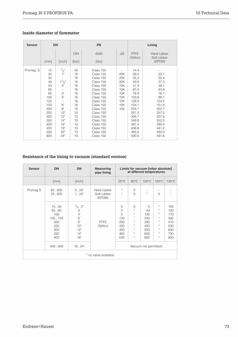
Inside diameter of flowmeter
Resistance of the lining to vacuum (standard version)
Sensor DN PN Lining
[mm] [inch]
DIN
[bar]
ANSI
[lbs]
JIS PTFE(Teflon)
Hard rubberSoft rubber
(EPDM)
Promag S 15253240506580
100125150200250300350400450500600
1/2"1"–
11/2"2"–3"4"–6"8"
10"12"14"16"18"20"24"
401616161616161616161010101010101010
Class 150Class 150Class 150Class 150Class 150Class 150Class 150Class 150Class 150Class 150Class 150Class 150Class 150Class 150Class 150Class 150Class 150Class 150
–20K20K20K10K10K10K10K10K10K10K
14.926.535.240.951.367.078.9
103.9128.9154.1204.7257.2306.7349.8387.4436.8485.0590.0
–23.732.437.348.163.976.799.1
124.5151.9202.7257.0307.9352.0390.4441.2492.0591.6
Sensor DN DN Measuringpipe lining
Limits for vacuum [mbar absolute]at different temperatures
[mm] [inch] 25°C 80°C 100°C 120°C 130°C
Promag S 65...60025...600
3...24"1...24"
Hard rubberSoft rubber
(EPDM)
**
00
–*
–0
––
15...5065...80
100125...150
200250300350400
1/2...2"3"4"6"8"
10"12"14"16"
PTFE(Teflon)
000
135200330400465530
0********
040
135240290400500600665
*********
100130170385410530630730800
450...600 18...24" Vacuum not permitted!
* no value available
Promag 35 S PROFIBUS PA 10 Technical Data
Endress+Hauser 73
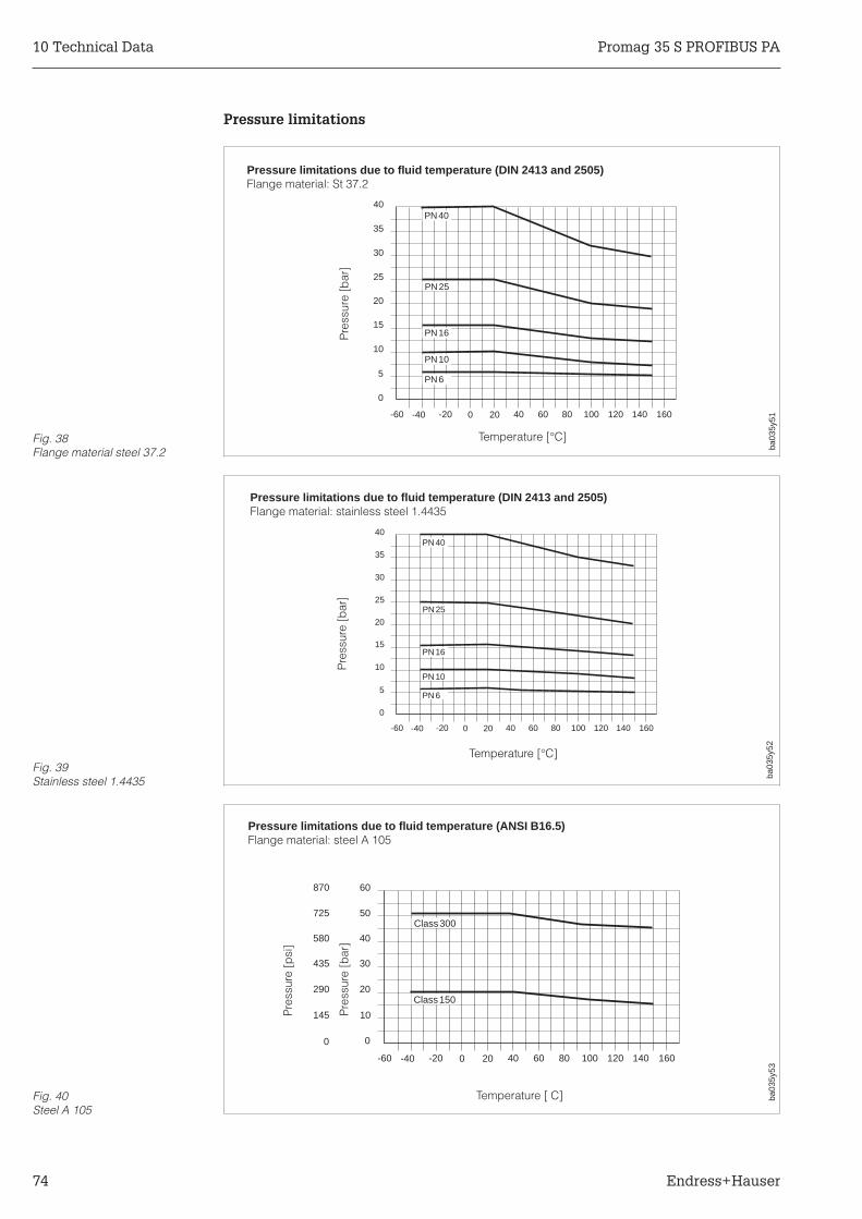
Pressure limitations
-60 -40 -20 0 20 40 60 80 100 120 140 160
0
5
10
15
20
25PN25
PN16
PN10
PN6
35
30
40PN40
Pressure limitations due to fluid temperature (DIN 2413 and 2505)Flange material: St 37.2
Temperature [°C]
Pre
ssur
e[b
ar]
ba03
5y51
Fig. 38Flange material steel 37.2
-60 -40 -20 0 20 40 60 80 100 120 140 160
0
5
10
15
20
25PN25
PN16
PN10
PN6
35
30
40PN40
ba03
5y52Temperature [°C]
Pre
ssur
e[b
ar]
Pressure limitations due to fluid temperature (DIN 2413 and 2505)Flange material: stainless steel 1.4435
Fig. 39Stainless steel 1.4435
0
145
290
435
580
725
870
-60 -40 -20 0 20 40 60 80 100 120 140 160
0
10
20
30
40
50Class300
Class150
60
ba03
5y53
Temperature [ C]
Pre
ssur
e[b
ar]
Pre
ssur
e[p
si]
Pressure limitations due to fluid temperature (ANSI B16.5)Flange material: steel A 105
Fig. 40Steel A 105
10 Technical Data Promag 35 S PROFIBUS PA
74 Endress+Hauser

Pressure limitations (continued)
-60 -40 -20 0 20 40 60 80 100 120 140 160
00
10145
20290
30435
40580
50725
Class300
Class150
60870
Pressure limitations due to fluid temperature (ANSI B16.5)Flange material: steel 316L
ba03
5y54
Temperature [°C]
Pre
ssur
e[b
ar]
Pre
ssur
e[p
si]
Fig. 41Steel 316L
Promag 35 S PROFIBUS PA 10 Technical Data
Endress+Hauser 75
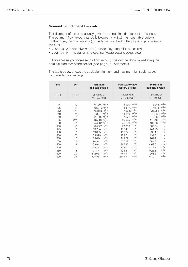
Nominal diameter and flow rate
The diameter of the pipe usually governs the nominal diameter of the sensor.The optimum flow velocity range is between v = 2...3 m/s (see table below).Furthermore, the flow velocity (v) has to be matched to the physical properties ofthe fluid:• v <2 m/s: with abrasive media (potter’s clay, lime milk, ore slurry)• v >2 m/s: with media forming coating (waste water sludge, etc.)
If it is necessary to increase the flow velocity, this can be done by reducing thenominal diameter of the sensor (see page 15 “Adapters”).
The table below shows the scalable minimum and maximum full scale valuesinclusive factory settings.
DN DN Minimumfull scale value
Full scale valuefactory setting
Maximumfull scale value
[mm] [inch] (Scaling atv ~ 0.3 m/s)
(Scaling atv ~ 2.5 m/s)
(Scaling atv ~ 10 m/s)
15253240506580
100125150200250300350400450500600
1/2"1"
11/4"11/2"2"
21/2"3"4"5"6"8"
10"12"14"16"18"20"24"
0.1909 m3/h0.5310 m3/h0.8686 m3/h1.3572 m3/h2.1206 m3/h3.5838 m3/h5.4287 m3/h8.4823 m3/h
13.254 m3/h19.085 m3/h33.929 m3/h53.014 m3/h76.341 m3/h
103.91 m3/h135.72 m3/h171.77 m3/h212.06 m3/h305.36 m3/h
1.5904 m3/h4.4179 m3/h7.2382 m3/h
11.310 m3/h17.671 m3/h29.865 m3/h45.239 m3/h70.686 m3/h
110.45 m3/h159.04 m3/h282.74 m3/h441.79 m3/h636.17 m3/h865.90 m3/h
1131.0 m3/h1431.4 m3/h1767.1 m3/h2544.7 m3/h
6.3617 m3/h17.671 m3/h28.953 m3/h45.239 m3/h70.686 m3/h
119.46 m3/h180.96 m3/h282.74 m3/h441.79 m3/h636.17 m3/h
1131.0 m3/h1767.1 m3/h2544.7 m3/h3463.6 m3/h4523.9 m3/h5725.6 m3/h7068.6 m3/h
10179 m3/h
10 Technical Data Promag 35 S PROFIBUS PA
76 Endress+Hauser

11 IndexIndex
AAccess code . . . . . . . . . . . . . . . 49Adapters . . . . . . . . . . . . . . . . . 15Addressing PROFIBUS PA by DIP switch . . . . 57Alarm messages . . . . . . . . . . . . . . 63All-weather cover . . . . . . . . . . . . . 11Ambient temperature . . . . . . . . . . . . 71Amplifier mode . . . . . . . . . . . . . . 46Assign line 1 . . . . . . . . . . . . . . . 41Assign line 2 . . . . . . . . . . . . . . . 41Axis of the electrodes . . . . . . . . . . . . 13
BBarrel . . . . . . . . . . . . . . . . . . 36Base support for the sensor . . . . . . . . . 12Bus address . . . . . . . . . . . . . . . 43
CCable entries . . . . . . . . . . . . . . . 72Cable glands . . . . . . . . . . . . . . . 11Cable length . . . . . . . . . . . . . . . 70Cable length maximum . . . . . . . . . . . 19Cable specifications . . . . . . . . . . . . 26Cathodic protection . . . . . . . . . . . . 20CE mark . . . . . . . . . . . . . . . . . 73CIP cleanable . . . . . . . . . . . . . . . 72Commissioning . . . . . . . . . . . . . . 27Conductivity . . . . . . . . . . . . . . . 71Connecting the transmitter . . . . . . . . . . 23Connection diagram of the remote version . . . 26Connection diagrams . . . . . . . . . . . . 24Connection of the remote version . . . . . . . 25Contrast LCD . . . . . . . . . . . . . . . 42Correct usage . . . . . . . . . . . . . . 5, 7Correct usage of the measuring system . . . . . 7Creep suppression . . . . . . . . . . . . . 69Current output . . . . . . . . . . . . . . . 24Current span . . . . . . . . . . . . . . . 38
DDangerous chemicals . . . . . . . . . . . . 6Dangers and notes . . . . . . . . . . . . . 5Data Memory (DAT) . . . . . . . . . . . . 9Degree of protection IP 67 (EN 60529) . . . . . 11Degree of protection IP 67 (EN 60529) 11 . . . . 71Delay . . . . . . . . . . . . . . . . . . 47Diagnostic function . . . . . . . . . . . . . 61DIP switches . . . . . . . . . . . . . . . 57Display damping . . . . . . . . . . . . . . 41Display elements . . . . . . . . . . . . . 29Display format . . . . . . . . . . . . . . . 41Display turning . . . . . . . . . . . . . . 18Downward pipe . . . . . . . . . . . . . . 15Dynamic response . . . . . . . . . . . . . 8
EElectrical connection . . . . . . . . . . . . 23Electrical isolation . . . . . . . . . . . . . 69Electrode axis . . . . . . . . . . . . . . . 13Electrode EPD . . . . . . . . . . . . . . . 54Electronics compartment . . . . . . . . . . 8EMC . . . . . . . . . . . . . . . . 21, 71Empty pipe detection (EPD) . . . . . . . . . 45Empty pipe detection electrode . . . . . . . . 8EPD electrode . . . . . . . . . . . . . . . 54EPD response time . . . . . . . . . . . . . 45Error (measured error) . . . . . . . . . . . . 70Error messages . . . . . . . . . . . . . . 62
FFaile safe mode . . . . . . . . . . . . . . 38Flow direction . . . . . . . . . . . . . . . 46Flow rate . . . . . . . . . . . . . . . . . 41Flow rate . . . . . . . . . . . . . . . . . 78Flow rate unit . . . . . . . . . . . . . . . 35Fluid temperature . . . . . . . . . . . . . 71Frequency . . . . . . . . . . . . . . . . 72Full scale . . . . . . . . . . . . . . . . . 37Function of the operating elements . . . . . . . 30Fuse replacement . . . . . . . . . . . . . 64
GGallons . . . . . . . . . . . . . . . . . 36Gaskets . . . . . . . . . . . . . . . . . 16Ground connection . . . . . . . . . . . . . 24Gsd- and Type files . . . . . . . . . . . . . 55
IInlet and outlet run . . . . . . . . . . . . . 70Inside diameter . . . . . . . . . . . . . . 74Installation . . . . . . . . . . . . . . 11, 14Instructions for troubleshooting . . . . . . . . 60Instrument functions . . . . . . . . . . . . 35
KK-Factor negative . . . . . . . . . . . . . 52K-Factor positive . . . . . . . . . . . . . . 52
LLanguage . . . . . . . . . . . . . . . . 42Load . . . . . . . . . . . . . . . . . . 69Low flow cutoff . . . . . . . . . . . . . . . 44
MMaterials . . . . . . . . . . . . . . . . . 72Matrix . . . . . . . . . . . . . . . . . . 31Measuring electrode . . . . . . . . . . . 8, 13Measuring mode . . . . . . . . . . . . . . 46Measuring point designation . . . . . . . . . 43Measuring principle . . . . . . . . . . . . 69Measuring range . . . . . . . . . . . . . . 69
Promag 35 S PROFIBUS PA Index
Endress+Hauser 77

Measuring system Promag 35 S . . . . . . . . 7Mechanical support of the sensor . . . . . . . 13Milk coupling . . . . . . . . . . . . . . . 67Mounting . . . . . . . . . . . . . . . . . 11Mounting instructions . . . . . . . . . . . . 13Mounting location . . . . . . . . . . . . . 14Mounting position . . . . . . . . . . . . . 13Mounting Promag 35 S . . . . . . . . . . . 16Mounting the remote version . . . . . . . . . 19Mounting the sensor . . . . . . . . . . . . 13Mounting the transmitter . . . . . . . . . . . 19
NNoise suppression . . . . . . . . . . . . . 44Nominal current . . . . . . . . . . . . . . 39Nominal diameter . . . . . . . . . . . 53, 77Nominal pressure . . . . . . . . . . . . . 71
OOperating elements . . . . . . . . . . . . . 29Operation overview . . . . . . . . . . . . . 29Operational safety . . . . . . . . . . . . . 9Outputs . . . . . . . . . . . . . . . . . 8
PPartly filled pipes . . . . . . . . . . . . . . 14Pipes partly filled . . . . . . . . . . . . . . 14Positive zero return (PZR) . . . . . . . . . . 48Potential equalization . . . . . . . . . . . . 20Power consumption . . . . . . . . . . . . . 72Power supply . . . . . . . . . . . . 8, 24, 72Power supply cable . . . . . . . . . . . 23, 24Power supply failure . . . . . . . . . . . . 72Present system condition . . . . . . . . . . 50Pressure limitations . . . . . . . . . . . . . 76Pressure loss . . . . . . . . . . . . . . . 71Previous system condition . . . . . . . . . . 50Private code . . . . . . . . . . . . . . . 48Profibus PA connection . . . . . . . . . . . 24PROFIBUS PA interface . . . . . . . . . 55, 56PROFIBUS PA parameters . . . . . . . . . . 58Programming . . . . . . . . . . . . . . . 32Programming enabling . . . . . . . . . . . 32Programming example . . . . . . . . . . . 33Programming locking . . . . . . . . . . . . 32Programming matrix . . . . . . . . . . . . 31Pumps installation . . . . . . . . . . . . . 15
RReference electrode . . . . . . . . . . . . 8Repairs . . . . . . . . . . . . . . . . 6, 64Repeatability . . . . . . . . . . . . . . . 70Reset Totalizer . . . . . . . . . . . . . . . 40Resistance of lining to vacuum . . . . . . . . 74Response to faults and alarms . . . . . . . . 59
SSampling rate . . . . . . . . . . . . . . . 53Sampling rate maximum . . . . . . . . . . . 53Screw tightening torques . . . . . . . . . . . 17Self checking . . . . . . . . . . . . . . . 49Serial number . . . . . . . . . . . . . . . 53Setting bus address via Touch Control . . . . . 56Setting the bus address . . . . . . . . . . . 56Short Instructions . . . . . . . . . . . . . . 2Signal cable . . . . . . . . . . . . . . 23, 24Simulation current . . . . . . . . . . . . . 39Software version . . . . . . . . . . . . . . 51Software version communication module . . . . 51Status messages . . . . . . . . . . . . . . 62System configuration . . . . . . . . . . . . 43System description . . . . . . . . . . . . . 7System condition . . . . . . . . . . . . . . 50
TTechnical data . . . . . . . . . . . . . . . 69Temperature ranges . . . . . . . . . . . . . 11Terminal compartment . . . . . . . . . . . . 8Time constant . . . . . . . . . . . . . . . 37Total overflow . . . . . . . . . . . . . . . 40Total volume . . . . . . . . . . . . . . . . 40Touch Control . . . . . . . . . . . . . 29, 56Transport instructions . . . . . . . . . . . . 12Troubleshooting . . . . . . . . . . . . . . 59Turning the local display . . . . . . . . . . . 18Turning the transmitter housing . . . . . . . . 18
UUnit nominal diameter . . . . . . . . . . . . 36Unit volume . . . . . . . . . . . . . . . . 36
VVibration . . . . . . . . . . . . . . . 13, 71
WWeights . . . . . . . . . . . . . . . 65, 66
ZZero point . . . . . . . . . . . . . . . . 52
Index Promag 35 S PROFIBUS PA
78 Endress+Hauser


Europe
Austria Endress+Hauser Ges.m.b.H.WienTel. (01) 880 56-0, Fax (01) 88056-35
BelarusBelorgsintezMinskTel. (0172) 26 3166, Fax (0172) 26 3111
Belgium / Luxembourg Endress+Hauser S.A./N.V.BrusselsTel. (02) 248 0600, Fax (02) 24805 53
BulgariaINTERTECH-AUTOMATIONSofiaTel. (02) 6528 09, Fax (02) 6528 09
Croatia Endress+Hauser GmbH+Co.ZagrebTel. (01) 6601418, Fax (01) 6601418
CyprusI+G Electrical Services Co. Ltd.NicosiaTel. (02) 4847 88, Fax (02) 4846 90
Czech Republic Endress+Hauser GmbH+Co.OstravaTel. (069) 661 19 48, Fax (069) 6 612869
Denmark Endress+Hauser A/SSøborgTel. (31) 6731 22, Fax (31) 6730 45
EstoniaElvi-Aqua-TehTartuTel. (07) 4227 26, Fax (07) 4227 27
Finland Endress+Hauser OyEspooTel. (90) 859 6155, Fax (90) 85960 55
France Endress+HauserHuningueTel. 389 69 6768, Fax 38969 4802
Germany Endress+Hauser Messtechnik GmbH+Co.Weil am RheinTel. (0 7621) 975-01, Fax (0 7621) 975-5 55
Great Britain Endress+Hauser Ltd.ManchesterTel. (01 61) 2 865000, Fax (01 61) 9 981841
GreeceI & G Building Services Automation S.A.AthensTel. (01) 924 1500, Fax (01) 92217 14
HungaryMile Ipari-ElektroBudapestTel. (01) 261 5535, Fax (01) 26155 35
IcelandVatnshreinsun HFReykjavikTel. (00354) 88 9616, Fax (00354) 889613
IrelandFlomeaco Company Ltd.KildareTel. (0 45 ) 8 68615, Fax (045) 868182
Italy Endress+Hauser Italia S.p.A.Cernusco s/N MilanoTel. (02) 9210 64 21, Fax (02) 92 107153
LatviaRaita Ltd.RigaTel. (02) 264023, Fax (02) 264193
LithuaniaAgava Ltd.KaunasTel. (07) 2024 10, Fax (07) 2074 14
Netherlands Endress+Hauser B.V.NaardenTel. (0 35) 6 958611, Fax (0 35) 6 9588 25
Norway Endress+Hauser A/STranbyTel. (0 32) 85 10 85, Fax (032) 8511 12
Poland Endress+Hauser Polska Sp. z o.o.WarsawTel. (022) 65101 74, Fax (022) 6 51 0178
PortugalTecnisis - Tecnica de Sistemas IndustriaisLinda-a-VelhaTel. (01) 417 26 37, Fax (1) 41852 78
RomaniaRomconseng SRLBucharestTel. (01) 410 16 34, Fax (01) 4 1016 34
RussiaAvtomatika-Sever Ltd.St. PetersburgTel. (0 812) 556 13 21 , Fa x (0 812)5 561321
Slovak RepublicTranscom Technik s.r.o.BratislavaTel. (07) 521 31 61, Fax (07) 5 2131 81
Slovenia Endress+Hauser D.O.O.LjubljanaTel. (061) 15922 17, Fax (061) 1 59 2298
Spain Endress+Hauser S.A.BarcelonaTel. (3) 480 3366, Fax (3) 473 38 39
Sweden Endress+Hauser ABSollentunaTel. (08) 626 16 00, Fax (08) 6 2694 77
Switzerland Endress+Hauser AGReinach/BL 1Tel. (0 61) 7 156222, Fax (0 61) 7 1116 50
TurkeyIntek Endüstriyel Ölcü ve Kontrol SistemleriIstanbulTel. (0212) 2 7513 55, Fax (02 12) 2 6627 75
UkraineIndustria UkraïnaKievTel. (044) 26852 13, Fax (044) 2 68 5213
Africa
MoroccoOussama S.A.CasablancaTel. (02) 241338, Fax (02) 402 657
South Africa Endress+Hauser Pty. Ltd.SandtonTel. (11) 444 13 86, Fax (11 ) 4 44 1977
TunisiaControle, Maintenance et RegulationTunisTel. (01) 793077, Fax (01) 7885 95
America
ArgentinaServotron SACIFIBuenos AiresTel. (01) 70 21 12 2 , Fax ( 0 1 ) 3 3401 04
BoliviaTritec S.R.L.CochabambaTel. (042) 56993, Fax (042) 5 09 81
BrazilServotekSao PauloTel. (01) 536 34 55, Fax (011) 5 36306 7
Canada Endress+Hauser Ltd.Burlington, OntarioTel. (905) 6 81 9292, Fax (9 05) 6 819444
ChileDIN Instrumentos Ltda.SantiagoTel. (02) 20501 00, Fax (02) 2 258139
ColombiaColsein Ltd.Santafe de Bogota D.C.Tel. (01) 23676 59, Fax (01) 6 107868
Costa RicaEURO-TEC S.A.San JoseTel.(0506) 29615 42, Fax(0506) 2 9615 42
EcuadorInsetec Cia. Ltda.QuitoTel. (02) 46 1833, Fax (02) 461833
GuatemalaACISA Automatiziacion Y ControlCiudad de Guatemala, C.A.Tel. (02) 334 5985, Fax (02) 332 74 31
MexicoEndress+Hauser Instruments InternationalMexico City Office, Mexico D.F.Tel. (05) 568 9658 , Fa x (0 5 ) 56 8 4 18 3
ParaguayINCOEL S.R.L.AsuncionTel. (021) 20 3465, Fax (021) 2 6583
PeruEsim S.A.LimaTel. (01) 47146 61, Fax (01) 4 710993
UruguayCircular S.A.MontevideoTel. (02) 92 5785, Fax (02) 929151
USA Endress+Hauser Inc.Greenwood, IndianaTel. (0317) 535-71 38, Fax (0317) 535-14 89
VenezuelaH. Z. Instrumentos C.A.CaracasTel. (02) 97988 13, Fax (02) 9 799608
Asia
China Endress+Hauser ShanghaiTel. (021) 64646700, Fax (02 1 )6 47 47 86 0
Hong Kong Endress+Hauser (H.K.) Ltd.Hong Kong Tel.(0852) 25 2831 20,Fax (0852) 2865 4171
India Endress+Hauser India Branch OfficeMumbaiTel. (022) 6 0455 78, Fax (022) 604 0211
IndonesiaPT Grama BazitaJakartaTel. (021) 7 9750 83, Fax (021) 797 5089
Japan Sakura Endress Co., Ltd.TokyoTel. (422) 5406 11, Fax (422) 5502 75
Malaysia Endress+Hauser (M) Sdn. Bhd.Petaling Jaya, Selangor Darul EhsanTel. (3) 733 48 48, Fax 03) 733 8800
PakistanSpeedy AutomationKarachiTel. (021) 772 2953, Fax (021)773 6884
PhilippinesBrenton Industries Inc.Makati Metro ManilaTel. (2) 843 06 61, Fax (2) 81757 39
Singapore Endress+Hauser (S.E.A.) Pte., Ltd.SingaporeTel. (065) 56682 22, Fax (065) 5 66 6848
South KoreaHitrol Co. Ltd.Bucheon CityTel. (032) 6 723131, Fax (032) 672 00 90
TaiwanKingjarl CorporationTaipei R.O.C.Tel. (02) 7 1839 38, Fax (02) 7 13 4190
Thailand Endress+Hauser Ltd.BangkokTel. (02) 9 9678 11-20, Fax (02) 9 967810
VietnamTan Viet Bao Co. Ltd.Ho Chi Minh CityTel. (08) 8 3352 25, Fax (08) 8 33 5227
IranTelephone Technical Services Co. Ltd.TehranTel. (021) 8 74675054, Fax (021) 8 73 7295
IsraelInstrumetrics Industrial Control Ltd.Tel-AvivTel. (03) 6 4802 05, Fax (03) 6 47 1992
JordanA.P. Parpas Engineering S.A.AmmanTel. (06) 559283, Fax (06) 559205
Kingdom of Saudi ArabiaAnasiaJeddahTel. (03) 6 71 00 14 , Fax ( 03 ) 6 72 59 29
KuwaitKuwait Maritime & Mercantile Co. K.S.C.SafatTel. (05) 2 4347 52, Fax (05)24414 86
LebanonNetwork Engineering Co.JbeilTel. (01) 325 40 51, Fax (01) 99 440 80
Sultanate of OmanMustafa & Jawad Sience & Industry Co.L.L.C.RuwiTel. (08)6020 09, Fax (08) 6070 66
United Arab EmiratesDescon Trading EST.DubaiTel. (04) 35 9522, Fax (04) 35 9617
YemenYemen Company for Ghee and Soap IndustryTaizTel. (04) 23 0665, Fax (04) 21 2338
Australia + New Zealand
AustraliaGEC Alsthom LTD.SydneyTel. (02) 6 4507 77, Fax (02) 9 64 50 81 8
New ZealandEMC Industrial InstrumentationAucklandTel. (09) 4 4492 29, Fax (09) 4 44 1145
All other countries
Endress+Hauser GmbH+Co.Instruments International
Weil am Rhein, GermanyTel. (076 21) 9 75-02, Fax (076 21) 97 53 45
12. 97/E+H II Members of the Endress+Hauser Group
Hauser+Endress