ba-2021-00 page: 1 stealth big air kit - yamaha … custom accessories/ba-202… · ba-2021-00...
TRANSCRIPT

Page: 1BA-2021-00STEALTH BIG AIR KIT - Yamaha Roadliner/Stratoliner andRaider
If you question your abilities it may be best for an experienced servicetechnician perform this installation. A Yamaha Service Manual would be
helpful to have on hand for reference.Revision: 8.4 - 03/30/2010Install Time: 2 to 3 hours
INCLUDED IN THE KIT:
(2) Billet Topped Reusable High Flow Filter
(2) Oval Velocity Intake Funnel Base Mount
(1) Coil Mount Plate
(1) Black Fuel Pressure Regulator Mount
(1) Formed Steel Fuel Line
(2) Small Hose Clamp SS
(1) 2" Crankcase Vent Filter w/3/8" Male Fitting
(1) 2" Idle Speed Air Filter w/1/2" Male Fitting
(1) Crankcase Vent Hose 3/8"i.d. x 8"
(2) M10 x 1.25 x 35mm Cap Head Allen Bolt
(2) M10 Flat Washer
(1) M10 x 1.25 Flange Nut
(8) Black Zip Tie
(4) M5 x .80 x 16mm SS Cap Head Bolt
(4) M5 x.80 Flange Nut
(14) M6 x 1.0 x 20mm SS Cap Head Bolt
(14) M6 x 1.0 Flange Nut
(14) M6 x Flat Washer
(2) O-Ring for Intake Funnel Base Mount
TOOLS REQUIRED:
8mm-10mm-12mm-14mm Wrenches & Sockets
4, 5, 6, & 8 Metric Allen Wrenches
3mm 4" Extended Allen Wrench
T-30 TORX Head Allen
Phillips and Standard Screwdrivers
INSTRUCTIONS:
NOTE: This kit can be installed on Yamaha Stratoliners/Roadliners & Raiders. There are subtle differences in the models.
STAGE I
1. Remove your seat and the left side cover (you will need a specialty T-30 Torx socket to remove the rear side cover bolt and a 4mm allen to remove thefront inner bolt.2. Remove the 8mm hex bolts from the seat lock on the backside of the cover and set the cover aside.3. Remove the 12mm hex bolts from the battery brace and we recommend you disconnect the positive battery cable for safety.4. Remove the rubber caps from each of the fuel control valves, then use a flat-tip screwdriver to close the valves by gentle turning the brass screwheads clockwise until they seat.5. Each fuel control valve has a retaining clip that secures it to the battery brace. Leave the clips closed on each fuel control valve but release the smallbarbed insert that attaches them to the battery brace. Then move the brace out of the way.
CAUTION: Moving forward from here you will be removing fuel lines. In each case please use caution as a small amount of fuel may be released. Wesuggest having a shop towel ready for cleanup.
NOTE: Beneath each fuel control valve is a "T" junction attached to a rubber fuel hose, follow each hose from the "T" down to the white 90 degreeelbow coming out of the secondary fuel tank. Release each retaining clamp securing the hose to each fitting. Leave the center hose where it lies but takethe left hose and pull it forward from under the frame rail and out to the side of frame so the tank can be removed.
6. Remove the (2) m10 crown nuts from the rear fuel tank mount.7. Remove the 5mm allen bolts from the rear and front of the chrome dash mount. Raise the dash up and disconnect the electrical connections attachedthe wiring harness. Then set the dash aside.
NOTE: It is a good idea to cover the tank with a soft towel to prevent any scratches from occurring while disconnecting the dash plugs.
8. Disconnect the small white electrical connection on the left front side of the tank and remove the small rubber hose at the top front right of the tank.
Our install guides provide a basic outline on the proper installation of our products. Further tuning and/orfitment may be required. Barons bears no responsibility on installation costs associated with this product.
© 2012 Barons Custom Accessories
5221 Oceanus Drive Huntington Beach, CA 92649 (925)583-2499 - Ph. (714)901-0520 - Fax www.baronscustom.com [email protected]

Page: 2BA-2021-00STEALTH BIG AIR KIT - Yamaha Roadliner/Stratoliner andRaider
FRONT FUEL TANK MOUNT REMOVAL:
RAIDER FRONT TANK MOUNT: Remove the (2) 4mm allen bolts from the triangle shaped aluminum cover at the front of the fuel tank and set itaside. Then remove two 6mm cap head allen bolts sitting beneath the cover. Lift the tank up and off the bike.
ROADLINER/STRATOLINER FRONT TANK MOUNT: Remove the (2) decorative fins at the front of the fuel tank by removing the (2) #4 allen boltsfrom each side of the tank. Remove the allen bolts from the fuel tank mount at the front of the tank. Lift the tank straight up and off the bike.
AIR BOX REMOVAL:
1. Remove the (2) m10 bolts from the rear of the air box attaching the air pressure sensor to the air box. Remove the (1) m10 bolt from the front sensorbracket located about three inches from the front right side of the air box. Remove the electrical leads and air hose to each sensor and disconnect themfrom their mount brackets. Set these sensors aside we will remount them later. See photo 1:
2. Remove the 5mm allen bolt attaching the air box mount tab bracket to the frame at the front of the air box.3. RAIDER ONLY: Disconnect the (7) electrical wiring leads connected to the wiring mount bracket on the top of the air box. Do not panic! Theseconnectors are mated male and female connectors and can only connect to their appropriate mate. Open the reusable zip ties holding the wiringbundles to the mount plate.
RAIDER & LINERS: At the front of the air box above the front cylinder disconnect the idle air hose from the front of the air box:
4. Remove the two small hoses from the left side of the air box.5. Remove the crankcase vent hose from the rear of the air box. You may also remove the hose from the top of the rear cylinder, it will be replacedlater.6. Under the air box loosen the retaining clamps securing the air box to the throttle bodies. It is best to reach these by going through, past and underthe left and right upper motor mounts. An extended 3mm ball allen wrench will be necessary. You can remove the motor mounts for easier access. Aflashlight or work light is very helpful in locating the clamp screws.
LINER NOTE: The forward mount tab of the air box attaches over the top of the front fuel tank mount. You must remove the two allen bolts at thefront of the tank mount and the one allen the goes through the bracket where the frame rails come together and then remove the air box with the tankmount bracket attached. Once off the bike you must remove the smaller allen connecting the air box to the bracket and then remove the rubbergrommet you will expose when the air box bracket is removed, set the grommet aside do not reuse it. Then re-attach tank mount bracket using only thetwo larger allen bolts to the frame. For now just set the single center bracket allen back in the hole and start the threads, you will attach the new coilmount plate to this hole and use the stock bolt later in the installation.
7. After both clamps are loosened lift the air box straight up and off the bike. There will be two vacuum hoses that must be released for the front rightside of the air box before you can set the air box aside. You will not reuse the air box.8. You should place a clean cloth inside each throttle body to keep any foreign material from entering your engine. Don't forget to remove cloth materialwhen you begin to install your new filter assembly.9. RAIDER ONLY: Remove wiring mount bracket from the top of the air box by removing the (2) phillips head screws from the top of the air box.
Our install guides provide a basic outline on the proper installation of our products. Further tuning and/orfitment may be required. Barons bears no responsibility on installation costs associated with this product.
© 2012 Barons Custom Accessories
5221 Oceanus Drive Huntington Beach, CA 92649 (925)583-2499 - Ph. (714)901-0520 - Fax www.baronscustom.com [email protected]

Page: 3BA-2021-00STEALTH BIG AIR KIT - Yamaha Roadliner/Stratoliner andRaider
INSTALLING NEW FILTER ASSEMBLY:
The left velocity filter base will sit with the oblong portion pointed to the 2:00 position being sure it is not touching the cylinder head and the rightvelocity filter base will sit at the 12:00 position.
NOTE: These velocity filter bases are a tolerance fit so they require firm constant pressure to install. See photo series 2:
1. Take the velocity filter base and install the o-rings into the slots in the base of each unit if they are not already installed.2. Place a velocity filter base down over the top of the throttle body until the o-ring contacts the top of the throttle body, now press down firmly on thevelocity base to get the o-ring to slide past the top and down the body until the top of the throttle body is evenly aligned with the lip on the inside of thebase above the o-ring. When the base is on correctly you will see an even seem around the entire circumference. If the seam is not even you must adjustwith pressure until it is. It may be necessary to use a soft blow mallet to attain a proper fit. Install on each throttle body.DO NOT moisten or lubricate these o-rings or the metal around them. See photo series 2:
3. Loosen the screw clamp on the new high flow filter/s. Look inside each filter and you will see the point of the power cone, be sure the filter is installedon the velocity filter base with the point directly over the center of the throttle body. Be sure the clamp screws are placed on the side and direction ofthe filters that allows you to get your tool on them. Tighten the clamp being sure to not over-tighten it or the filter will be driven off the velocity filterbase. Repeat on both sides. See photo 3:
4. Check the left filter to be sure it is not touching the head. Rotate the base for clearance if necessary. Check to be sure the throttle linkage bracket isnot touching the filter. If it is touching, pull/tweak the bracket outward slightly as needed.5. Install the UP-123 uni-filter on the hose you disconnected from the front of the air box earlier. Use the supplied screw clamp to secure it to the hose.Take a zip tie and attach the filter to the vacuum lines or wiring harness to hold it high enough so it cannot be seen from the side of the bike.6. Install the rubber hose supplied in the kit on to the crankcase vent spout on top of the rear cylinder, reuse the clamp that previously secured theoriginal crankcase vent hose in position. Install the UP-122 uni-filter on to the end of this hose and secure with supplied clamp.
TIME FOR A DECISION:
At this point, if you wish to leave your coils and stock engine side covers in place, move on to steps 7 thru 12. Re-install the fuel tank, seat andside cover. You are now ready to visit the local tuning shop to maximize performance with the installation of a Power Commander®. However ifyou wish to clean up the sides of your engine by removing these covers and all the related clutter contained under and around these covers thenproceed to STAGE II section bypassing steps 7 thru 12 at this time.
AIR SENSORS:
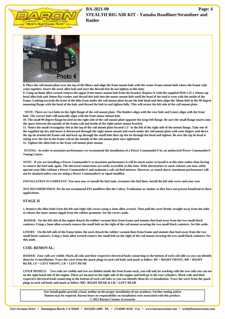
7. Take the black coil mount plate and attach the air sensors you removed from the stock air box earlier and attach them as follows. Using thesupplied m6-1.0 x 16mm cap head allen bolts and m6 flange nut attach one sensor to the very rear of the coil mount plate to the two holes locatedin the bent tail section. The air nozzle/spout will point towards the engine. Attach the front air sensor to the foremost two parallel 6mm holesjust behind the center front 8mm mount hole. The electrical receiver points towards the engine and the nozzle/spout points towards the rear ofthe bike. The bolts should go through the sensor and into the coil mount plate then thread and tighten the flange nuts. Connect the rearelectrical lead to sensor and insert the small vacuum line onto the nozzle/spout.NOTE: It will be necessary to trim appox. 2" of the wiring sheath away from the wiring loom at the front of the bike in order to release the airsensor electrical lead so it can properly connect to the sensor. See photo 4:
Our install guides provide a basic outline on the proper installation of our products. Further tuning and/orfitment may be required. Barons bears no responsibility on installation costs associated with this product.
© 2012 Barons Custom Accessories
5221 Oceanus Drive Huntington Beach, CA 92649 (925)583-2499 - Ph. (714)901-0520 - Fax www.baronscustom.com [email protected]
Page: 4BA-2021-00STEALTH BIG AIR KIT - Yamaha Roadliner/Stratoliner andRaider
8. Place the coil mount plate over the top of the filters and align the front mount hole with the center frame mount hole where the frame railscome together. Insert the stock allen bolt and start the threads but do not tighten at this time.9. Using an 8mm allen wrench remove the upper front motor mount bolt from the bracket. Replace it with the supplied M10-1.25 x 35mm caphead allen bolt and 10mm flat washer and thread this bolt into the motor mount hole until the head of the stud is even with the inside of theframe. Looking towards the front of the bike from under the coil mount plate locate the bolt head and then align the 10mm hole in the 90 degreemounting flange with the head of the bolt, and thread the bolt in and tighten fully. This will secure the left side of the coil mount plate.
NOTE: There are two holes in the right flange of the coil mount plate. The Raiders align with the rear hole and Liners align with the fronthole. The correct hole will naturally align with the front motor mount bolt.10. The small 90 degree flange located on the right side of the coil mount plate opposite the large left flange. Be sure the small flange inserts intothe space between the outside of the frame rail and inside of the right motor mount bracket.11. Notice the small rectangular slot in the top of the coil mount plate located 1.5" to the left of the right side of the mount flange. Take one ofthe supplied zip ties and insert it downward through the right motor mount and reach under the coil mount plate with your fingers and directthe zip tie around the frame rail and back up through the small hole then zip the tie through the head and tighten. Be sure the zip tie head issitting over the slot in the frame rail on the outside of the coil mount plate once tightened.12. Tighten the allen bolt at the front coil mount plate mount.
TUNING: In order to maximize performance we recommend the installation of a Power Commander® by an authorized Power Commander®Tuning Center.
NOTE: If you are installing a Power Commander® to maximize performance it will be much easier to install it at this time rather than havingto remove the fuel tank again. The electrical connections are easily accessible at this time. With aftermarket or stock exhaust you may safelyoperate your bike without a Power Commander® and maintain a safe air/fuel mixture. However, as stated above, maximum performance willnot be attained unless you are using a Power Commander® or equal modifier.
INSTALLATION IS COMPLETE: You may now re-install the fuel tank, reconnect the fuel lines, install the left side cover and your seat.
NOT RECOMMENDED: We do not recommend EFI modifiers like the Cobra, Techlusions or similar as they have not proven beneficial in theseapplications.
STAGE II
1. Remove the allen bolts from the left and right side covers using a 5mm allen wrench. Then pull the cover firmly straight away from the sidesto release the inner mount nipple from the rubber grommet. Set the covers aside.
RAIDER: On the left side of the engine detach the rubber vacuum lines from frame and mounts that lead away from the two small blackcanisters. Using a 3mm allen wrench remove the small bolt on the right of the coil mount securing the two small black canisters. Set this aside.
LINERS: On the left side of the frame below the neck detach the rubber vacuum lines from frame and mounts that lead away from the twosmall black canisters. Using a 3mm allen wrench remove the small bolt on the right of the coil mount securing the two small black canisters. Setthis aside.
COIL REMOVAL:
RAIDER: Four coils are visible. Mark all coils and their respective electrical leads connecting to the bottom of each coil sides so you can identifythem for re-installation. Trace the wires from the spark plugs to each coil body and mark as follow: RF = RIGHT FRONT, RR = RIGHTREAR, LF = LEFT FRONT, LR = LEFT REAR
LINER MODELS: Two coils are visible and two are hidden inside the front frame neck, you will only be working with the two coils you can seeon the right hand side of the engine. These are located on the right side of the engine and both go to the rear cylinders. Mark coils and theirrespective electrical leads connecting to the bottom of each coil sides so you can identify them for re-installation. Trace the wires from the sparkplugs to each coil body and mark as follow: RR= RIGHT REAR & LR = LEFT REAR
Our install guides provide a basic outline on the proper installation of our products. Further tuning and/orfitment may be required. Barons bears no responsibility on installation costs associated with this product.
© 2012 Barons Custom Accessories
5221 Oceanus Drive Huntington Beach, CA 92649 (925)583-2499 - Ph. (714)901-0520 - Fax www.baronscustom.com [email protected]

Page: 5BA-2021-00STEALTH BIG AIR KIT - Yamaha Roadliner/Stratoliner andRaider
YOU MAY PROCEED AFTER THE COILS AND ELECTRICAL CONNECTIONS ARE CLEARLY MARKED.
2. Using a 5mm allen wrench remove the upper and lower bolts securing each coil to their mount brackets. Disconnect the black & whiteelectrical leads from the bottom of each coil. Remove the spark plug cap from the plugs and set each coil aside. Some of the plug wires will be ziptied to the upper frame rail. Cut these zip ties to release the wires, then use a supplied zip tie to re-secure the rubber dampers and other wires tothe frame.
PRESSURIZED FUEL RETURN VALVE:
3. Remove the coil mounting brackets and set them aside. Remove the bracket attaching the pressurized fuel return valve and let it hang. Youwill not reuse the stock coil mounts for re-mounting the coils but may use them for remounting the stock side covers at the end of theinstallation. See photo 5:
4. Remove the left motor mount from the left side of the engine by removing the (2) 10mm dome head allen bolts at the top of the motor mountusing an 8mm allen Wrench, then remove the (2)14mm hex nuts at the bottom of the mount secured to the top of each cylinder. See photo 6above:5. You can now easily access and release the pinch clamp on the rubber hose connected to the end of the pressurized fuel return valve whichconnects to the hard (metal) fuel line. Remove the hard line from the short rubber hose, then release the pinch clamp on the long rubber hoseconnected to the other end of the hard fuel line and remove the hard line from the bike. You will not reuse this hard line. See photo 6 above:CAUTION: This is a fuel return line and is connected to the secondary fuel tank. A small amount of fuel usually escapes from this line duringremoval. Once removed it is important plug or keep the open end raised so no additional fuel escapes.
6. The pressurized fuel return valve must be pulled apart and the nipple rotated 180 degrees and then pushed back together. See photo series 7:
NOTE: The pressurized fuel return valve lines on the RAIDER have a black connection at the short 90 degree end and an orange connection atthe straight end. The LINERS have orange connections at both ends. It is important/mandatory the short 90 degree end be connected to thebase of the throttle body. Photo
7. If the 90 degree end is not connected to the base of the throttle body you must remove and rotate the line and make the connection properly atthis time. See photo 6 above:8. Pressurized fuel return valve FITTING DISCONNECTION: Slide the black or orange plastic safety lock back from the fitting, this exposestwo Gray buttons on either side of the connection. You must depress both buttons while simultaneously pulling the connections away from thenipple.9. Attach the pressurized fuel return valve to the new small black bracket (supplied) using (2) m5 x 16 cap head screws (supplied) See photo 8:
NOTE: The mount tab from the pressurized fuel return valve sits on the inside of the new mount. The cap head screws go through thepressurized fuel return valve mount tab and thread into the new black bracket and should be tightened firmly. See photo 8:
Our install guides provide a basic outline on the proper installation of our products. Further tuning and/orfitment may be required. Barons bears no responsibility on installation costs associated with this product.
© 2012 Barons Custom Accessories
5221 Oceanus Drive Huntington Beach, CA 92649 (925)583-2499 - Ph. (714)901-0520 - Fax www.baronscustom.com [email protected]

Page: 6BA-2021-00STEALTH BIG AIR KIT - Yamaha Roadliner/Stratoliner andRaider
10. Reinstall the left motor mount attaching it to the cylinder heads first by threading the m14 Hex bolts (removed earlier) back into the cylinderheads. Using (1) m10 x 1.25 x 35mm cap head bolt and one m10 flat washer (supplied) insert into the rear upper motor mount and tighten. Aportion of this bolt will protrude through the frame rail once it is properly tightened.11. Place the bracket with the pressurized fuel return valve attached on the inside on the frame over the left rear cylinder. Insert the open end ofthe pressurized fuel return valve line onto the male fitting of the pressurized fuel return valve until the fitting seats firmly then snap the safetyconnector closed. (You should hear a click or snap) See photo 9 above:12. Place the oval mount hole of the new bracket with pressurized fuel return valve attached over the m10 bolt that now protrudes inside theframe rail and thread the m10 Flange nut (supplied) then slide/adjust this bracket as needed to be sure the pressurized fuel return valve line isnot touching throttle linkage or the cylinder head. Be sure to manipulate the throttle fully while watching to be sure you have adjusted the line toclear the linkage fully. Photo 8 above:13. Take the new hard fuel line (supplied) and insert the longer end into the long rubber fuel hose leading to the secondary fuel tank and install ascrew clamp (supplied) over the hose at the junction and tighten.14. Place a screw clamp over the short rubber hose at the top of the pressurized fuel return valve and insert the curved end of the new hard fuelline into the hose and align the screw clamp with the junction and tighten firmly.
AIR SENSOR:
15. Take the black coil mount plate and attach the air sensors you removed from the stock air box earlier and attach them as follows. REARSENSOR: Using the supplied m6-1.0 x 16mm cap head allen bolts and m6 Flange nut attach sensor to the very rear of the coil mount plate to thetwo holes located in the 90 degree bend in the rear tail section. The air nozzle/spout will point down towards the engine. See photo 4 above:
NOTE: It will be necessary to trim appox. 2" of the wiring sheath away from the wiring loom at the front of the bike in order to release the airsensor electrical lead so it can properly connect to the sensor.
FRONT AIR SENSOR ATTACHMENT: Using the supplied m6-1.0 x 16mm cap head allen bolts and m6 flange nut attach as described below:
RAIDER: Attach sensor to the foremost two parallel 6mm holes just behind the center front 8mm mount hole. The electrical connection pointstowards the engine and the nozzle/spout points towards the rear of the bike. The bolts should go through the sensor up into the coil mount platethen thread and tighten the flange nuts firmly. Connect the electrical leads to each sensor and insert the small vacuum line onto the nozzle/spout.
LINERS: Attach sensor to the two parallel 6mm holes located to the right of the coil cutout on the front right of the coil mount plate Theelectrical connection points down towards the engine and the nozzle/spout points towards the left frame rail. The bolts should go through thesensor up into the coil mount plate then thread and tighten the flange nuts firmly. Connect the electrical leads to each sensor and insert the smallvacuum line onto the nozzle/spout.
INSTALL COILS:
16. Using the m6 cap head screws and flange nuts mount the coils to the coil mount plate. All bolts insert through the coil mount and a spacerwasher is placed over the exposed bolt, then insert the bolts through the coil mount plate and tighten an m6 flange nut down firmly against thetop of the coil mount plate. See photo 10:
Our install guides provide a basic outline on the proper installation of our products. Further tuning and/orfitment may be required. Barons bears no responsibility on installation costs associated with this product.
© 2012 Barons Custom Accessories
5221 Oceanus Drive Huntington Beach, CA 92649 (925)583-2499 - Ph. (714)901-0520 - Fax www.baronscustom.com [email protected]

Page: 7BA-2021-00STEALTH BIG AIR KIT - Yamaha Roadliner/Stratoliner andRaider
RAIDER COILS: The front coil/s mount in the two cutouts at the front of the coil mount plate with the plug wires extending towards the front ofthe bike. Attach the coils so they sit over their respective cylinders FL & FR . The rear coils attach in the remaining cutouts with the wiresextending towards the left side of the bike. The left rear coil attaches to the cutout closest to the front of the bike.
LINER COILS: The front coils remain in place inside the frame neck. The rear coils should be located in the cutouts on the left of the coilmount plate
ELECTRICAL CONNECTIONS: Connect the White and Black electrical connection back to their coordinating coils as you marked earlier.
PLUG WIRES: Connect each of the plug wires to the appropriate spark plug being sure the spark plug boot slides firmly and completely on tothe plug.
RAIDER ELECTRICAL CONNECTION MOUNT BRACKET: Take the wiring bracket you removed from the top of the stock air box andattach it to the top of the coil mount plate using the two holes that align with the bracket mount tabs using the m5 x 15 cap head screws and m5flange nuts and tighten firmly.
INSTALLING THE COIL MOUNT PLATE:
16. Take the coil mount plate and rotate it into position above the filters bringing the front of the mount into place over the front mount hole ofthe frame. Be sure all plug wires route around and between the filters and the coil mount plate can sit down into place without binding any lines,wires or hoses. Be sure the wiring looms are in their correct positions and are not pinched by the coil mount plate.17. Place the dome head allen bolt removed earlier from the front air box mount through the front coil mount plate hole and get the threadsstarted but do not tighten.18. Using an 8mm allen wrench thread the supplied M10-1.25 x 35mm cap head allen bolt and 10mm flat washer into the front left motor mounthole until the head of the stud is even with the inside of the frame. From the left rear of the coil mount plate look towards the front of the bikeunder the coil mount plate locate the new bolt head and align it with the 10mm hole in the coil mount plates large 90 degree mount flange thenthread the bolt in and tighten into the frame fully. This will secure the left side of the coil mount plate. NOTE: There are two holes in the rightflange of the coil mount plate. The correct hole naturally aligns with the front motor mount bolt of the Raider and 'Liners.NOTE: Raiders align with the rear hole, Liners align with the front hole.19. Align and slide the small 90 degree flange on the right side of the coil mount plate down into the slot between outside of the frame rail andthe inside of the right motor mount bracket.20. Notice the small rectangular slot in the top of the coil mount plate located 1.5" to the left of the right side at the mount inside of the smallflange. Insert one of the zip ties (supplied) downward through the slot behind the right motor mount while reaching under the coil mount platewith your fingers and re-directing the zip tie around the frame rail and then up through the small hole in the coil mount plate. Zip the tiethrough the head and tighten being sure the zip tie head is sitting directly over the slot in the frame rail on the outside of the coil mount plateonce tightened.21. Tighten the allen bolt at the front coil mount plate.
ELECTRICAL CONNECTIONS:
RAIDER: Reconnect the wiring leads on the right side of the frame to the stock wiring bracket now attached to the coil mount plate thenreconnect the leads from the left side of the frame being sure they all connect fully and lock firmly. Reconnect the three small leads towards therear of the wiring bracket and lock them in place under the rubber strap. CAUTION: These smaller connections have terminals that bendeasily. Use caution when working with these, it may be necessary to align the terminals if they become bent as they may not slide into theirreceivers properly in which case the male and female connectors will not lock in place.
LINER: Requires no other stock wiring be connected at this time in order to install the tank.
Our install guides provide a basic outline on the proper installation of our products. Further tuning and/orfitment may be required. Barons bears no responsibility on installation costs associated with this product.
© 2012 Barons Custom Accessories
5221 Oceanus Drive Huntington Beach, CA 92649 (925)583-2499 - Ph. (714)901-0520 - Fax www.baronscustom.com [email protected]

Page: 8BA-2021-00STEALTH BIG AIR KIT - Yamaha Roadliner/Stratoliner andRaider
RECOMMENDED TUNING: In order to maximize performance we recommend the installation of a Power Commander® by an authorizedPower Commander® Tuning Center.
NOT RECOMMENDED: We do not recommend EFI modifiers like the Cobra, Techlusions or similar as they have proven to not be effective inthese applications.
NOTE: If you are installing a Power Commander® to maximize performance it will much easier to install it at this time rather than having toremove the fuel tank again. The electrical connections are easily accessible at this time. With aftermarket or stock exhaust you may safelyoperate your bike without a Power Commander® and maintain a safe air/fuel mixture. However, as stated above, maximum performance willnot be attained unless you are using a Power Commander® or equal modifier.
INSTALLATION IS COMPLETE:
You may now re-install the fuel tank, reconnect the fuel lines, install the left side cover and your seat. Be certain to properly re-connect the fuellines to the fuel control valves and open them correctly.
ENGINE SIDE COVER OPTIONS: You will have the following options at the end of the install as it relates to the side of your engine:Use no covers and possible replace a few exposed bolts with chrome or black hardware. Specialty bolt covers are available on the marketwhich would also add a nice touch. (not supplied)Reuse the stock left and right side covers. This will require you to reinstall the stock cover mounting brackets but you will have nothingmounted behind them.Use/purchase Baron's Engine Side Cover Kit BA-7624 to add dynamic element to the sides of your engine while covering your motormounts and related hardware. These kits include necessary hardware and mounting instructions.
Our install guides provide a basic outline on the proper installation of our products. Further tuning and/orfitment may be required. Barons bears no responsibility on installation costs associated with this product.
© 2012 Barons Custom Accessories
5221 Oceanus Drive Huntington Beach, CA 92649 (925)583-2499 - Ph. (714)901-0520 - Fax www.baronscustom.com [email protected]