ba 450/530 ba 5321 - southeastern equipment - ba 5321.pdfelectric traction motor brush (or carbon...
TRANSCRIPT

BA 450/530BA 5321
08812876(1)2002-01
SERVICE MANUAL

Nilfisk-Advance Italia S.p.ALocalità Novella Terza26862 Guardamiglio (Lodi) Italiawww.nilfisk-advance.comPhone: +39 0377 451124Fax: +39 0377 51443
Printed in Italy
SERVICE MANUAL GB
INDEX
GENERAL INFORMATION 51MACHINE LIFTING 51MACHINE TRANSPORTATION 51MACHINE PUSHING OR TOWING 51OTHER AVAILABLE MANUALS FOR BA 450/530 51SAFETY - ACCIDENT PREVENTION 52
GENERAL SAFETY RULES 52TECHNICAL DATA 53MAINTENANCE 55
SCHEDULED MAINTENANCE 55MACHINE NOMENCLATURE 56
DETERGENT SUPPLY SYSTEM 58DETERGENT TANK AND SUPPLY SYSTEM CLEANING 58DETERGENT FILTER CLEANING 58SOLENOID VALVE AND DETERGENT FLOW TAP REPLACEMENT 59DETERGENT FLOW CABLE AND CONTROL LEVER REPLACEMENT 60TROUBLESHOOTING 61
SMALL AMOUNT OF THE DETERGENT OR NO DETERGENT REACHES THE BRUSH 61THE DETERGENT REACHES THE BRUSH ALSO WHEN THE MACHINE IS OFF 61
SWEEPING SYSTEM 62BRUSH MOTOR ELECTRICAL INPUT CHECK 62BRUSH MOTOR REPLACEMENT 63BRUSH REDUCTION UNIT REPLACEMENT 64BRUSH ROTATION CONSENT MICRO-SWITCH ADJUSTMENT 66TROUBLESHOOTING 67
OPEN CIRCUIT 67THE BRUSH DOES NOT ROTATE 67
RECOVERY SYSTEM 68FLOAT SHIELD AND SUCTION PRE-FILTER CLEANING 68SUCTION PRE-FILTER ASSEMBLY REPLACEMENT 69TANK COVER GASKET AND COMPENSATION HOLE CHECK 70SUCTION MOTOR ELECTRICAL INPUT CHECK 71SUCTION MOTOR REMOVAL 72SUCTION MOTOR BRUSH/CARBON BRUSH CHECK AND REPLACEMENT 73RECOVERY WATER DRAIN PIPE REMOVAL 74SUCTION CAP CHECK/CLEANING AND POSSIBLE FLAPS REPLACEMENT 75DUST AND DEBRIS COLLECTION SYSTEM SUCTION CAP REMOVAL 76TROUBLESHOOTING 77
DIRTY WATER SUCTION IS INSUFFICIENT OR THERE IS NO SUCTION 77THE SUCTION CAP LEAVES LINING OR DOES NOT COLLECT WATER 77
TRACTION SYSTEM 78TRACTION MOTOR ELECTRICAL INPUT CHECK 78TRACTION MOTOR REMOVAL 80TRACTION MOTOR BRUSH (OR CARBON BRUSH) CHECK AND REPLACEMENT 82POTENTIOMETER ADJUSTMENT 84TROUBLESHOOTING 85
OPEN CIRCUIT 85THE MACHINE DOES NOT MOVE 85
08812876(1)2002-01 49

SERVICE MANUALGB
ELECTRICAL SYSTEM 86BATTERY REMOVAL 86BATTERY MAINTENANCE AND RECHARGING 86TRACTION ELECTRONIC BOARD REPLACEMENT 86
ELECTRICAL SYSTEM 87SERVICE ELECTRONIC BOARD REPLACEMENT 87TROUBLESHOOTING 88COMPONENT LAYOUT 88WIRING DIAGRAM BA 450/530 - after serial number 014106978 90WIRING DIAGRAM BA 5321 - after serial number 1514570 94WIRING DIAGRAM BA 5321D - after serial number 1514570 95
50 08812876(1)2002-01
SERVICE MANUAL
GENERAL INFORMATIONGB
GENERAL INFORMATIONMACHINE LIFTING
MACHINE TRANSPORTATION
MACHINE PUSHING OR TOWING
OTHER AVAILABLE MANUALS FOR BA 450/530
The following manuals are available by Nilfisk Literature Service Department:– BA 450/530 Part List – Nilfisk Form Number 08603654(2)00-12– BA 450/530 Use and Maintenance Manual.- Nilfisk Form Number 08812382(2)2001-03
WARNING!Do not work under the lifted machine if it is not securely fixed.
WARNING!Before transporting the machine, ensure that:
• All doors and carters are closed• The ignition key is not inserted• The machine is fastened to the mean of transportation
WARNING!Do not move the machine by pushing or towing it, unless you follow the procedures describedin the Use and Maintenance Manual. If you do not follow the specified procedures the machinecan be damaged.
08812876(1)2002-01 51

SERVICE MANUAL
GENERAL INFORMATIONGB
SAFETY - ACCIDENT PREVENTION
Nilfisk uses the following symbols to indicate potentially dangerous situations. Always read carefully thisinformation and take the necessary precautions to protect people and objects.
GENERAL SAFETY RULES
Specific warnings and cautions to inform about potential damages to people and machine are shown below.
DANGER!Indicates the risk of being injured or the risk of death.
WARNING!Indicates the risk of being injured.
CAUTION!Indicates the risk of light injuries to people, machine or other objects.
WARNING!To perform maintenance/repair procedures, put the machine on a flat floor, turn the ignition keyto OFF position and disconnect the battery.This machine must be used by qualified and authorized personnel only.Keep the battery far from sparks, flames and smoke. During the normal operation explosivegases are delivered.Do not wear jewels when working near electrical components.Do not work under the lifted machine if it is not securely fixed.Do not operate the machine near inflammable liquids or vapors.
CAUTION!Carefully read all maintenance/repair instructions before carrying out any maintenance/repairprocedure.Take all necessary precautions to prevent hair, jewels and loose dresses from being caught bythe machine moving parts.Battery charging produces explosive hydrogen gas. Charge the batteries only in good ventilatedareas and far from naked flames.Do not smoke during battery charging.Do not leave the machine unattended on an inclined floor.Do not use the machine on slopes with an inclination higher than 2%.Do not wash the machine with pressurized water.Do not use the machine in too dusty areas.This machine is not suitable for picking up hazardous dust.If the temperature is below 0°, the water present into the reservoirs and into the pipes of themachine could freeze.During the use of this machine take care not to cause damage to people and children especially.This machine cannot be used on public roads.
52 08812876(1)2002-01

SERVICE MANUAL
GENERAL INFORMATIONGB
TECHNICAL DATA
Dimensions
BA 450 BA 530 BA 5321Suction width 30 in (770 mm) 30 in (770 mm) 30 in (770 mm)Sweeping width 17.7 in (450 mm) 20.8 in (530 mm) 20.8 in (530 mm)Machine length 49 in (1250 mm) 52 in (1330 mm) 52 in (1330 mm)Machine height at the maneuver handle 42.5 in (1078.5 mm) 42,5 in (1078,5 mm) 42,5 in (1078,5 mm)Brush dimension Ø 450 mm (17.7 in) Ø 530 mm (20.8 in) Ø 530 mm (20.8 in)Brush speed 180 RPM 180 RPM 180 RPMBrush pressure on the floor 34 Kg 27 kg 27 kgForward maximum speed (*) 4.5 km/h 4.5 km/h 4.5 km/hReverse maximum speed (*) 2.2 km/h 2.2 km/h 2.2 km/hMax slope 2 % 2 % 2 %Detergent tank capacity 13.2 gal (55 liters) 13.2 gal (55 liters) 13.2 gal (55 liters)Recovery water tank capacity 13.2 gal (55 liters) 13.2 gal (55 liters) 13.2 gal (55 liters)Machine weight (without batteries) 134 kg 134 kg 134 kgMachine weight (with standard batteries) 215 kg 215 kg 215 kgStandard battery weight 81 Kg 81 Kg 81 Kg
Batteries
Standard batteries (no. 2 batteries) 12 Volt, 100 Ah 12 Volt, 100 Ah 12 Volt, 100 AhBattery voltage 24 V 24 V 24 V
Battery housing, dimensions
Height 295 mm (11.5 in) 295 mm (11.5 in) 295 mm (11.5 in)Width 345 mm (13.5 in) 345 mm (13.5 in) 345 mm (13.5 in)Length 350 mm (13.5 in) 350 mm (13.5 in) 350 mm (13.5 in)
General technical characteristics
Electrical system voltage 24 V 24 V 24 VBrush motor 650 W - 1600 RPM 650 W - 1600 RPM 650 W - 1600 RPMSuction motor 500 W - 3300 RPM 500 W - 3300 RPM 500 W - 3300 RPMTraction motor 200 W - 120 RPM 200 W - 120 RPM 200 W - 120 RPMDirty water suction pressure 13 kPa 13 kPa 13 kPaAir intake 31 l/sec 31 l/sec 31 l/sec
(*) BA 450/530 with traction motor only
08812876(1)2002-01 53

SERVICE MANUAL
GENERAL INFORMATIONGB
S300161Dimensions expressed by mm
998
560,
5
443
770
BA 450 = 1250BA 530 / CA 5321 = 1330
1078
,5
54 08812876(1)2002-01

SERVICE MANUAL
GENERAL INFORMATIONGB
MAINTENANCE
SCHEDULED MAINTENANCE
The machine proper and safe operation is granted by a careful and constant maintenance.
The following table sums up the scheduled maintenance. The indicated periods can be subjected to variationsaccording to working conditions. These must be defined by the person in charge for the maintenance.For maintenance operation instructions see the following paragraphs.
See GENERAL INFORMATION and SAFETY - ACCIDENT PREVENTION
Maintenance operation On deliveryAfter use
(daily)
Every 25 hours (or weekly)
Every 100 hours
Every 200 hours
Battery charging •Battery liquid level and voltage (Volt) • •
Suction cap cleaning/check •Float shield and suction pre-filter cleaning •
Tank cover gasket check (vacuum chamber) •
Detergent tank and supply system cleaning •
Detergent filter cleaning •Hose and tank inspection •Nut and screw tightening check •Electric suction motor brush (or carbon brush) check and replacement
•
Electric traction motor brush (or carbon brush) check and replacement
•
08812876(1)2002-01 55

SERVICE MANUAL
GENERAL INFORMATIONGB
MACHINE NOMENCLATURE
In this Manual you find numbers in brackets – example: (2). These numbers refer to the components indicated inthe two nomenclature pages. Refer to these pages each time you want to find the component mentioned in thetext.
1. Speed control potentiometer (*) 23. Suction cap assembly
2. Main switch with key (*)3. Brush switch4. Suction switch5. Battery condition indicator6. Detergent flow control lever7. Hour counter8. Start/Stop activation panel9. Suction cap lifting/lowering handle10. Brush lifting/lowering pedal11. Water recovery tank12. Recovery tank automatic closing with float13. Suction pre-filter14. Detergent tank15. Suction motor16. Brush motor17. Traction adjusting handles18. Brush19. Integrated battery charger (**)20. Circuit panel21. Traction motor (*)22. Batteries56
24. Tank covers25. Recovery water drain pipe26. Detergent drain pipe27. Tank assembly28. Key (supplied with the machine)29. Tank assembly fastening screw30. Machine maneuver handle31. Battery frame32. Front wheel33. Driving wheels (*)34. Traction motor thermal fuse35. Brush motor thermal fuse36. Suction motor thermal fuse37. Brush reduction unit38. Suction cap balancing adjustment handwheel39. Traction switch (*)
(*) BA 450/530 with traction motor only(**) Optional
S300162
08812876(1)2002-01

SERVICE MANUAL
GENERAL INFORMATIONGB
MACHINE NOMENCLATURE (CONTINUE)
S300163
08812876(1)2002-01 57

SERVICE MANUAL
DETERGENT SUPPLY SYSTEMGB
DETERGENT SUPPLY SYSTEMDETERGENT TANK AND SUPPLY SYSTEM CLEANING
1. Empty the detergent tank (14) through the pipe (26).2. Take the detergent flow control lever (6) in wide-open position, then activate the machine until the detergent
inside the machine is exhausted.3. Carry out the Detergent filter cleaning (see the following procedure).
DETERGENT FILTER CLEANING
1. Drive the machine on a level ground.2. Turn the switch key (2) to OFF position.3. Operating on the left lower side of the machine, remove the cover (A) and the wire gauze (B), clean and install
them again on the related support (C).
4. Carry out step 1. and 2. in the reverse order.
Figure 1
S300164
Remark: The wire gauze (B) must be correctly positioned on the support (C) housing (D).
58 08812876(1)2002-01

SERVICE MANUAL
DETERGENT SUPPLY SYSTEMGB
SOLENOID VALVE AND DETERGENT FLOW TAP REPLACEMENT
1. Drive the machine on a level ground.2. Turn the switch key (2) to OFF position.3. If there is recovery water in the tank (11) remove it through the pipe (25).4. If there is detergent in the tank (14) remove it through the pipe (26).5. Remove the key (28) from its housing and remove the tank assembly fastening screw (29).6. Carefully lift the tank assembly (27) by means of the maneuver handle (30).7. Disconnect the battery (22) negative cable (-).8. Disconnect the other cables of the batteries.9. Remove the batteries (22).10. Remove the battery frame (31).11. Remove the screws (A) and the cover (B) of the electronic case, then disconnect the solenoid valve (D)
cables (C) from the electronic board connections (E) (connection electrical symbols: F1 and F4).
12. Disconnect the hoses (F and G).13. Remove the solenoid valve (D) fastening screws (H).14. Disconnect the tap (M) control lever (L) cable (I). If necessary loosen the cable sheath (O) fixing clamp (N).
15. Remove the solenoid valve assembly (D) with the tap (M).16. Remove the pipe unions (Q and S) at the cabinet bench.17. Remove the tap (M) from the solenoid valve (D).
18. Install in the reverse order of removal.Figure 2
S300165
Remark: For the BA 5321 (USA) version, disconnect the solenoid valve (D1) cables by removingthe screw (P) and disconnecting the electrical connection (R).
Remark: When reinstalling, fix the sheath (O) by means of the clamp (N) in the same position (seethe print on the sheath); in this way the adjustment of the tap control remains unchanged.
Remark: when reinstalling the solenoid valve (D), the stamping orientation (T) must be as shownin the figure; moreover, before installing the unions (Q and S) and the tap (M) clean the relatedthreads and apply LOCTITE 572 sealant.
08812876(1)2002-01 59

SERVICE MANUAL
DETERGENT SUPPLY SYSTEMGB
DETERGENT FLOW CABLE AND CONTROL LEVER REPLACEMENT1. Drive the machine on a level ground.2. Turn the switch key (2) to OFF position.3. Operating under the machine left side, loosen the sheath (D) fixing clamp (C) and disconnect the cable (A)
from the tap lever (B).4. Disconnect the sheath (D) from the fixing clamps along its run up to the lever (6).5. Remove the handgrip (F) from the lever (G).6. Remove the screws (H) and lightly slide the panel (I).7. Remove the screws (L) and the control lever with the cable (M).8. Install in the reverse order of removal and adjust the sheath terminal (D) position so that when the tap lever
(B) is in the position shown in the figure (closed) the control lever (G) is in “zero” flow position. When the lever(G) is in maximum flow position, the lever (B) rotates about 90°.
Figure 3
S300166
Figure 4
S300167
60 08812876(1)2002-01

SERVICE MANUAL
DETERGENT SUPPLY SYSTEMGB
TROUBLESHOOTING
SMALL AMOUNT OF THE DETERGENT OR NO DETERGENT REACHES THE BRUSH
Possible cause:1. The brush switch (3) is not to ON position or it is broken (turn it on or repair/replace it). 2. The detergent filter is obstructed/dirty (clean it).3. The detergent flow control lever does not control the related tap anymore (check the control lever cable, from
the lever to the tap).4. The detergent tap is stuck closed (replace the tap).5. The solenoid valve is broken or there is an open circuit in the electrical connection (replace the solenoid
valve/repair the electrical connection).6. There is debris in the detergent tank obstructing the output hole (clean the tank).7. There is debris in the detergent pipeline obstructing the detergent flow (clean the pipeline).
THE DETERGENT REACHES THE BRUSH ALSO WHEN THE MACHINE IS OFF
Possible cause:1. The solenoid valve is broken (replace it).
08812876(1)2002-01 61

SERVICE MANUAL
SWEEPING SYSTEMGB
SWEEPING SYSTEMBRUSH MOTOR ELECTRICAL INPUT CHECK
1. Remove the brush (18).2. Drive the machine on a level ground.3. Turn the switch key (2) to OFF position.4. If there is recovery water in the tank (11) remove it through the pipe (25).5. If there is detergent in the tank (14) remove it through the pipe (26).6. Remove the key (28) from its housing and remove the tank assembly fastening screw (29).7. To operate on the brush motor (16) carefully lift the tank assembly (27) by means of the maneuver handle
(30).8. Disconnect the battery (22) negative cable (-).9. Disconnect the motor electrical cables (A) from the connection (B).
10. Connect the brush motor to the machine battery, as described in the underlying diagram, inserting the 30 Afuse (D), for safety’s sake.
11. By means of an ammeter (C) check that the brush motor electrical input is 8-9 A at 24 V. If the input is greater,disassemble the motor (see the procedure on the following page), clean the motor properly and then checkits moving parts.If the above-mentioned procedures do not lead to a correct motor input it is necessary to replace the motor(see the procedure on the following page).
12. Carry out steps from 1. to 9. in the reverse order.
WARNING!This procedure must be performed by qualified personnel only.
WARNING!Pay attention to the brush flange rotation while performing the following steps.
Figure 1
S300168
62
Figure 2
S300169
C
D
30A
08812876(1)2002-01

SERVICE MANUAL
SWEEPING SYSTEMGB
BRUSH MOTOR REPLACEMENT
1. Remove the brush (18).2. Drive the machine on a level ground.3. Turn the switch key (2) to OFF position.4. If there is recovery water in the tank (11) remove it through the pipe (25).5. If there is detergent in the tank (14) remove it through the pipe (26).6. Remove the key (28) from its housing and remove the tank assembly fastening screw (29).7. To operate on the brush motor (16) carefully lift the tank assembly (27) by means of the maneuver handle
(30).8. Disconnect the battery (22) negative cable (-).9. Disconnect the motor electrical cables (A) from the connection (B).10. Cut the clamp (C).11. Remove the nuts (D) and the brush motor (E).12. Remove the spring pin (F) and the pinion (G) at the cabinet bench.13. Remove the bearing (H) and the gasket (I).
14. Remove the wire gauze (L).15. Install in the reverse order of removal.
CAUTION!When reinstalling, take care of assemble the bearing (H) with the smaller side (M) facing thepinion (as shown in the figure).
Figure 4
Figure 3S300170
08812876(1)2002-01
S300171
63
SERVICE MANUAL
SWEEPING SYSTEMGB
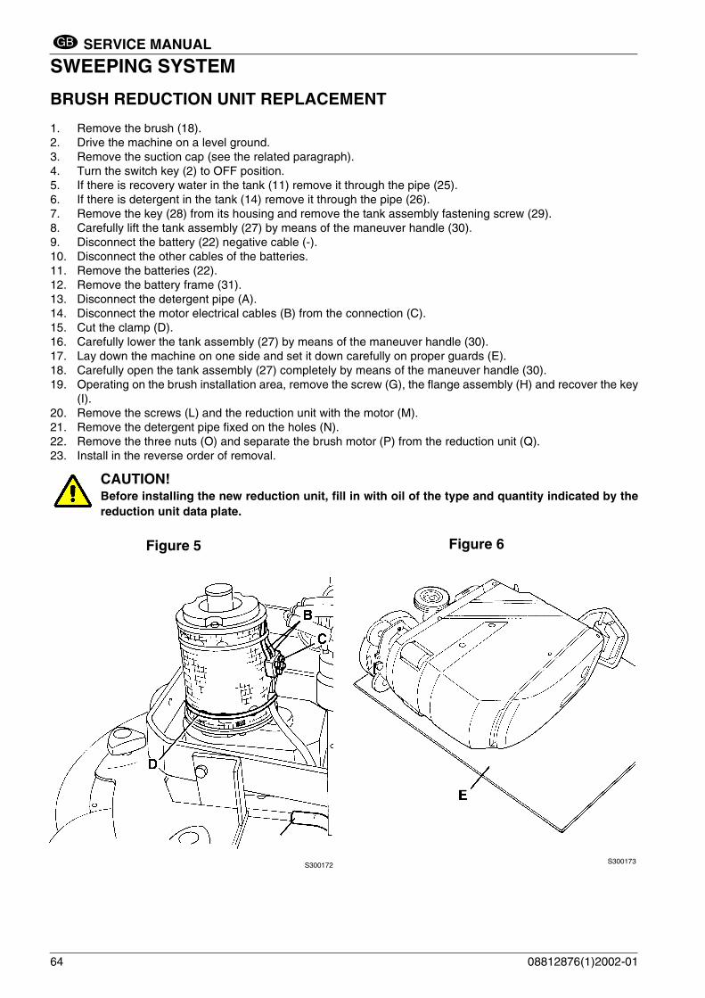
BRUSH REDUCTION UNIT REPLACEMENT
1. Remove the brush (18).2. Drive the machine on a level ground.3. Remove the suction cap (see the related paragraph).4. Turn the switch key (2) to OFF position.5. If there is recovery water in the tank (11) remove it through the pipe (25).6. If there is detergent in the tank (14) remove it through the pipe (26).7. Remove the key (28) from its housing and remove the tank assembly fastening screw (29).8. Carefully lift the tank assembly (27) by means of the maneuver handle (30). 9. Disconnect the battery (22) negative cable (-).10. Disconnect the other cables of the batteries.11. Remove the batteries (22).12. Remove the battery frame (31).13. Disconnect the detergent pipe (A).14. Disconnect the motor electrical cables (B) from the connection (C).15. Cut the clamp (D).16. Carefully lower the tank assembly (27) by means of the maneuver handle (30).17. Lay down the machine on one side and set it down carefully on proper guards (E).18. Carefully open the tank assembly (27) completely by means of the maneuver handle (30).19. Operating on the brush installation area, remove the screw (G), the flange assembly (H) and recover the key
(I).20. Remove the screws (L) and the reduction unit with the motor (M).21. Remove the detergent pipe fixed on the holes (N).22. Remove the three nuts (O) and separate the brush motor (P) from the reduction unit (Q).23. Install in the reverse order of removal.
CAUTION! Before installing the new reduction unit, fill in with oil of the type and quantity indicated by thereduction unit data plate.
Figure 5
S300172
64
Figure 6
S300173
08812876(1)2002-01

SERVICE MANUAL
SWEEPING SYSTEMGB
BRUSH REDUCTION UNIT REPLACEMENT (Continue)
Figure 7
S300174
08812876(1)2002-01 65

SERVICE MANUAL
SWEEPING SYSTEMGB
BRUSH ROTATION CONSENT MICRO-SWITCH ADJUSTMENT1. Drive the machine on a level ground.2. Turn the switch key (2) to OFF position.3. If there is recovery water in the tank (11) remove it through the pipe (25).4. If there is detergent in the tank (14) remove it through the pipe (26).5. Remove the key (28) from its housing and remove the tank assembly fastening screw (29).6. Carefully lift the tank assembly (27) by means of the maneuver handle (30).7. Disconnect the battery (22) negative cable (-).8. Carefully lower the tank assembly (27) by means of the maneuver handle (30).9. Remove the screws (A) and the activation panel (C) cover (B).10. With the activation panel (C) deactivated, check that the micro-switch (E) actuator (D) is in the cam (I)
housing (F).11. Activate the panel (C) and check that the actuator (D) is at the positions (G and H) and activates the
micro-switch (E) (a “click” must be heard).If necessary, reach the required condition by loosening the screws (L) and adjusting the cam position (I)and/or loosening the screws (M) and adjusting the micro-switch position (E). Tighten the screws.
12. Install in the reverse order of removal.13. Carry out some tests to check the brush rotation consent.
Figure 8
S300175
Figure 9
S300176
CAUTION! If the micro-switch electrical connections (N) have been disconnected, take care to connect themagain correctly.
66 08812876(1)2002-01

SERVICE MANUAL
SWEEPING SYSTEMGB
TROUBLESHOOTING
OPEN CIRCUIT
The thermal fuse (35) determines the open circuit. This system allows to prevent the brush motor circuits frombeing damaged under overload conditions.If there is an open in the electrical circuit, the possible causes are the following.
Brush motor; the thermal fuse (35) activates and opens the electrical circuit.
Possible cause:1. There are bulky debris or cords around the brush or between the brush and its flange (remove the brush and
the debris or cords).2. The brush motor electrical input is too high (check the electrical input).Wait at least 2 minutes after the break and, when the problem is solved, push the thermal fuse button (35).
THE BRUSH DOES NOT ROTATE
Possible cause:1. To avoid damaging the floor, the brush motor turns off automatically when the machine stands still in the
same position (the brush cannot stand still in the same position).2. The battery voltage is to low (charge the battery).3. The electrical motor brushes are worn (replace the electrical motor brushes).4. The electrical motor has a malfunction (repair or replace the electrical motor).5. The thermal fuse (35) is deactivated (remove the cause of deactivation).6. The brush ON/OFF switch (3) is broken (replace it).7. The reduction unit has a malfunction (repair or replace it).8. The brush rotation consent micro-switch is not correctly adjusted or is broken (adjust or replace it).9. The wiring harness is damaged (repair it).10. The electromagnetic switch is broken (replace it).
08812876(1)2002-01 67
SERVICE MANUAL
RECOVERY SYSTEMGB
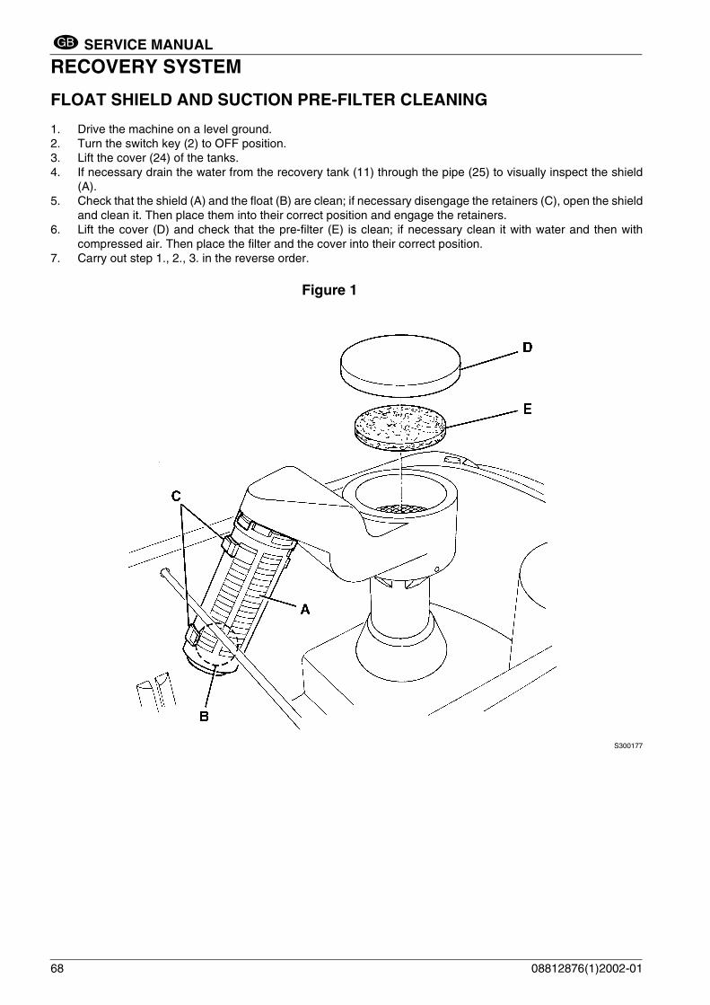
RECOVERY SYSTEMFLOAT SHIELD AND SUCTION PRE-FILTER CLEANING
1. Drive the machine on a level ground.2. Turn the switch key (2) to OFF position.3. Lift the cover (24) of the tanks.4. If necessary drain the water from the recovery tank (11) through the pipe (25) to visually inspect the shield
(A).5. Check that the shield (A) and the float (B) are clean; if necessary disengage the retainers (C), open the shield
and clean it. Then place them into their correct position and engage the retainers.6. Lift the cover (D) and check that the pre-filter (E) is clean; if necessary clean it with water and then with
compressed air. Then place the filter and the cover into their correct position.7. Carry out step 1., 2., 3. in the reverse order.
Figure 1
S300177
68 08812876(1)2002-01

SERVICE MANUAL
RECOVERY SYSTEMGB
SUCTION PRE-FILTER ASSEMBLY REPLACEMENT
1. Drive the machine on a level ground.2. Turn the switch key (2) to OFF position.3. Lift the cover (24) of the tanks.4. Drain all the water from the recovery tank (11) through the pipe (25).5. Disengage the retainers (A) and open the shield (B) by disengaging it from the pre-filter assembly. Recover
the float (C).6. Rotate the pre-filter assembly (D) in the direction indicated by the arrow to disengage the four retainers (E)
from their housings, then remove it upwards, overcoming the gasket (F) resistance.7. Clean the tank housing (G) and the new pre-filter assembly area (H).8. In the area (H) apply a thin coat of AREXONS spray silicone (silicon waterproofing lubricant).9. Carry out step 5. and 6. in the reverse order.10. Lift the cover (I) and check that the pre-filter (L) is clean.11. Carry out step 1., 2., 3. in the reverse order.
Figure 2
S300178
08812876(1)2002-01 69
SERVICE MANUAL
RECOVERY SYSTEMGB
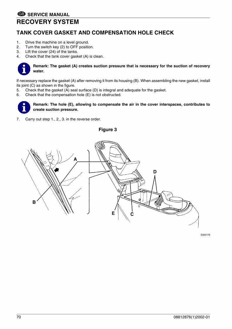
TANK COVER GASKET AND COMPENSATION HOLE CHECK
1. Drive the machine on a level ground.2. Turn the switch key (2) to OFF position.3. Lift the cover (24) of the tanks.4. Check that the tank cover gasket (A) is clean.
If necessary replace the gasket (A) after removing it from its housing (B). When assembling the new gasket, installits joint (C) as shown in the figure.5. Check that the gasket (A) seal surface (D) is integral and adequate for the gasket.6. Check that the compensation hole (E) is not obstructed.
7. Carry out step 1., 2., 3. in the reverse order.
Figure 3
S300179
Remark: The gasket (A) creates suction pressure that is necessary for the suction of recoverywater.
Remark: The hole (E), allowing to compensate the air in the cover interspaces, contributes tocreate suction pressure.
70 08812876(1)2002-01

SERVICE MANUAL
RECOVERY SYSTEMGB
SUCTION MOTOR ELECTRICAL INPUT CHECK
1. Drive the machine on a level ground.2. Turn the switch key (2) to OFF position.3. If there is recovery water in the tank (11) remove it through the pipe (25).4. If there is detergent in the tank (14) remove it through the pipe (26).5. Remove the key (28) from its housing and remove the tank assembly fastening screw (29).6. To operate on the suction motor (15) carefully lift the tank assembly (27) by means of the maneuver handle
(30).
7. Apply amperometric pliers (A) on a cable of the suction motor (B).8. Activate the suction motor by means of the button (4) and check that the motor electrical input is about 20 A
at 24 V. If the electrical input is greater carry out the motor brush check (see the procedure on the followingpages). If necessary, disassemble the suction motor (see the procedure on the following page), clean it andcheck its moving parts.If the above-mentioned procedures do not lead to a correct motor input it is necessary to replace the motor(see the procedure on the following page).
9. Carry out steps from 1. to 7. in the reverse order.
Figure 4
S300180
WARNING!This procedure must be performed by qualified personnel only.
WARNING! Do not touch uncovered electrical components while performing the following steps.
08812876(1)2002-01 71

SERVICE MANUAL
RECOVERY SYSTEMGB
SUCTION MOTOR REMOVAL
1. Drive the machine on a level ground.2. Turn the switch key (2) to OFF position.3. If there is recovery water in the tank (11) remove it through the pipe (25).4. If there is detergent in the tank (14) remove it through the pipe (26).5. Remove the key (28) from its housing and remove the tank assembly fastening screw (29).6. To operate on the suction motor (15) carefully lift the tank assembly (27) by means of the maneuver handle
(30).7. Disconnect the battery (22) negative cable (-).8. Disconnect the suction motor (D) electrical cables (B and C) from the connection (A).9. Remove the motor fastening screws (E).10. Remove the suction motor (D) and the joint (F).11. Recover the gasket (G) that is between the motor and the structure.12. Install in the reverse order of removal.
Figure 5
S300181
72 08812876(1)2002-01
SERVICE MANUAL
RECOVERY SYSTEMGB
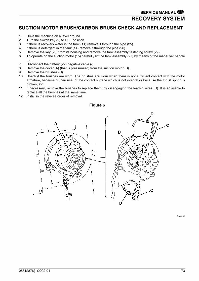
SUCTION MOTOR BRUSH/CARBON BRUSH CHECK AND REPLACEMENT
1. Drive the machine on a level ground.2. Turn the switch key (2) to OFF position.3. If there is recovery water in the tank (11) remove it through the pipe (25).4. If there is detergent in the tank (14) remove it through the pipe (26).5. Remove the key (28) from its housing and remove the tank assembly fastening screw (29).6. To operate on the suction motor (15) carefully lift the tank assembly (27) by means of the maneuver handle
(30).7. Disconnect the battery (22) negative cable (-).8. Remove the cover (A) (that is pressurized) from the suction motor (B).9. Remove the brushes (C).10. Check if the brushes are worn. The brushes are worn when there is not sufficient contact with the motor
armature, because of their use, of the contact surface which is not integral or because the thrust spring isbroken, etc.
11. If necessary, remove the brushes to replace them, by disengaging the lead-in wires (D). It is advisable toreplace all the brushes at the same time.
12. Install in the reverse order of removal.
Figure 6
S300182
08812876(1)2002-01 73

SERVICE MANUAL
RECOVERY SYSTEMGB
RECOVERY WATER DRAIN PIPE REMOVAL
1. Drive the machine on a level ground.2. Turn the switch key (2) to OFF position.3. If there is recovery water in the tank (11) remove it through the pipe (25).4. If there is detergent in the tank (14) remove it through the pipe (26).5. Remove the retaining flange (A) inside the tank (11).6. Remove the key (28) from its housing and remove the tank assembly fastening screw (29).7. Carefully lift the tank assembly (27) by means of the maneuver handle (30).8. Pull out the terminal (B) from the tank and remove the recovery water drain pipe (C).9. Before reinstalling the recovery water drain pipe, clean the hole (E). Ensure that the gasket (D) is present,
then warm its end (B) with hot water (to make it become softer) and insert it in the hole (E).10. Carry out step 6. and 7. in the reverse order.11. Install the retaining flange (A) after applying on its surface (F) a thin coat of AREXONS spray silicone (silicone
waterproofing lubricant).12. Carry out steps from 1. to 4. in the reverse order.
Figure 8
Figure 7S300183
74
S300184
08812876(1)2002-01

SERVICE MANUAL
RECOVERY SYSTEMGB
RECOVERY SYSTEMSUCTION CAP CHECK/CLEANING AND POSSIBLE FLAPS REPLACEMENT
1. Drive the machine on a level ground.2. Turn the switch key (2) to OFF position.3. Lower the suction cap assembly (23) by means of the handle (9).4. Disconnect the suction pipe (A) from the suction cap (C) and from the tank (Q); check that the internal part
of the pipe is free from dirt; otherwise clean it.5. Remove the handwheels (B) and the suction cap assembly (C).6. Check that the hole (D) and the spaces (E) are free from dirt; otherwise clean them.7. Check that the edges (I) of the front and rear flaps (F and G) lay down on the same level, along their length;
otherwise adjust their height as described below: – Disengage the retainer (L) and loosen the screws (M) to adjust the rear flap (G); then tighten the screws
and engage the retainer.– Loosen the nuts (N) to adjust the front flap (F); then tighten the nuts.
8. Check that the front and rear flap (F and G) are integral and free from cuts and lacerations; otherwise replacethem as described below. Check that the front corner (H) of the rear flap is not worn; if the rear corner isintegral overturn the flap. If the rear corner is worn, replace the flap as described below:– To replace (or overturn) the rear flap (G) disengage the retainer (L), remove the screws (M) and the
retaining strip (O). Install in the reverse order of removal.– To replace the front flap (F) remove the nuts (N) and the retaining strip (P). Install in the reverse order
of removal.After the flap replacement (or overturning), adjust their height as described by the previous step.
9. Reinstall the suction cap assembly (C) in the correct position and screw down the handwheels (B).10. Connect the suction pipe (A) to the suction cap (C) and to the tank (Q).11. If necessary, adjust the balancing handwheel (R) of the suction cap.
Figure 9
S300185
08812876(1)2002-01 75

SERVICE MANUAL
RECOVERY SYSTEMGB
RECOVERY SYSTEMSUCTION CAP CHECK/CLEANING AND POSSIBLE FLAPS REPLACEMENT (Continue)
Figure 10
S300186SISTEMA DI RACCOLTA DETRITI E POLVEREDUST AND DEBRIS COLLECTION SYSTEM SUCTION CAP REMOVAL 1. Drive the machine on a level ground.2. Turn the switch key (2) to OFF position.3. Lower the suction cap assembly (23) by means of the handle (9).4. Disconnect the suction pipe (A) from the suction cap (B).5. Remove the handwheels (C) and the suction cap assembly (B).6. Install in the reverse order of removal and, if necessary, adjust the balancing handwheel (D) of the suction
cap.Figure 11
S300187
76 08812876(1)2002-01

SERVICE MANUAL
RECOVERY SYSTEMGB
RECOVERY SYSTEMTROUBLESHOOTING
OPEN CIRCUITThe thermal fuse (36) determines the open circuit. This system allows to prevent the suction motor circuits frombeing damaged under overload conditions.If there is an open in the electrical circuit, the possible causes are the following.
Suction motor; the thermal fuse (36) activates and opens the electrical circuit.
Possible cause:1. The motor is damaged (check the motor brushes/electrical input).Wait at least 2 minutes after the break and, when the problem is solved, push the thermal fuse button (36).
DIRTY WATER SUCTION IS INSUFFICIENT OR THERE IS NO SUCTION
Possible cause:1. The float automatic closing (12) is activated because the water recovery tank (11) is too full (empty the water
recovery tank).2. The float shield (12) or the suction filter are dirty (clean them).3. The tank cover (24) is not correctly positioned (place it correctly).4. The tank cover gasket is not efficient or the compensating hole is obstructed (remove the causes).5. The suction cap or suction pipe obstructed or damaged (clean/repair/replace them)6. The battery voltage is to low (charge the battery).7. The Electrical motor brushes are worn (replace the electrical motor brushes).8. The electrical motor has a malfunction (repair or replace the electrical motor).9. The thermal fuse (36) is deactivated (remove the cause of deactivation).10. The suction ON/OFF switch (4) is broken (replace it).11. The wiring harness is damaged (repair it).12. The suction motor electromagnetic switch is broken (replace it).
THE SUCTION CAP LEAVES LINING OR DOES NOT COLLECT WATER
Possible cause:1. There is debris under the suction cap lip (remove them)2. The suction cap flap lips are torn or worn (replace the flaps)3. The suction cap is unbalanced (balance it by means of the handwheel (38)).
08812876(1)2002-01 77

SERVICE MANUAL
TRACTION SYSTEMGB
TRACTION SYSTEMTRACTION MOTOR ELECTRICAL INPUT CHECK
1. Drive the machine on a level ground.2. Turn the switch key (2) to OFF position.3. If there is recovery water in the tank (11) remove it through the pipe (25).4. If there is detergent in the tank (14) remove it through the pipe (26).5. Remove the key (28) from its housing and remove the tank assembly fastening screw (29).6. Carefully lift the tank assembly (27) by means of the maneuver handle (30).7. Disconnect the battery (22) negative cable (-).8. Disconnect the other cables of the batteries.9. Remove the batteries (22).10. Remove the battery frame (31).11. Remove the screws (A) and the electronic case cover (B).
Disconnect the traction motor (D) cables (C) from the connection (I) (electrical symbol T4) to the electronicboard and from the connection (L).
12. Lift the driving wheels (E) a few centimeters from the ground by inserting adequate shims under the brush(18) or under the front wheel (32). Then securely fix the machine in this position so that the driving wheels(E) can turn freely without touching the ground during the following tests.
13. Connect the traction motor to the machine battery, as described in the underlying diagram, inserting the 10A fuse (F), for safety’s sake.
14. With an ammeter check that the motor electrical input is about 3-4 A at 24 V. If the electrical input is greatercarry out the motor brush check (see the procedure on the following pages). If necessary, disassemble thetraction motor (see the procedure on the following page), clean it and check its moving parts.If the above-mentioned procedures do not lead to a correct motor input it is necessary to replace the motor(see the procedure on the following page).
15. Carry out steps from 1. to 12. in the reverse order.
WARNING! This procedure must be performed by qualified personnel only.
WARNING! Pay attention to the driving wheel (E) rotation while performing the following steps.
78 08812876(1)2002-01

SERVICE MANUAL
TRACTION SYSTEMGB
TRACTION MOTOR ELECTRICAL INPUT CHECK (Continue)
Figure 1
S300188
Figure 2
S300189
G
F
10A
08812876(1)2002-01 79

SERVICE MANUAL
TRACTION SYSTEMGB
TRACTION MOTOR REMOVAL
1. Remove the brush (18).2. Drive the machine on a level ground.3. Remove the suction cap (see the related paragraph).4. Turn the switch key (2) to OFF position.5. If there is recovery water in the tank (11) remove it through the pipe (25).6. If there is detergent in the tank (14) remove it through the pipe (26).7. Remove the key (28) from its housing and remove the tank assembly fastening screw (29).8. Carefully lift the tank assembly (27) by means of the maneuver handle (30).9. Disconnect the battery (22) negative cable (-).10. Disconnect the other cables of the batteries.11. Remove the batteries (22).12. Remove the battery frame (31).13. Remove the screws (A) and the electronic case cover (B).
Disconnect the traction motor (D) cables (C) from the connection (M) (electrical symbol T4) to the electronicboard and from the connection (N).
14. Carefully lower the tank assembly (27) by means of the maneuver handle (30).15. Remove the left wheel (F) and the snap ring (G).16. Lay down the machine on one side and set it down carefully on proper guards (H).17. Remove the right wheel (I).18. Remove the four screws (L).19. Remove the motor assembly with the reduction unit (D).20. Install in the reverse order of removal.
Figure 3
S300190
80 08812876(1)2002-01

SERVICE MANUAL
TRACTION SYSTEMGB
TRACTION MOTOR REMOVAL (Continue)
Figure 4
S300191
Figure 5
S300192
08812876(1)2002-01 81

SERVICE MANUAL
TRACTION SYSTEMGB
TRACTION MOTOR BRUSH (OR CARBON BRUSH) CHECK AND REPLACEMENT
1. Remove the brush (18).2. Drive the machine on a level ground.3. Remove the suction cap (see the related paragraph).4. Turn the switch key (2) to OFF position.5. If there is recovery water in the tank (11) remove it through the pipe (25).6. If there is detergent in the tank (14) remove it through the pipe (26).7. Remove the key (28) from its housing and remove the tank assembly fastening screw (29).8. Carefully lift the tank assembly (27) by means of the maneuver handle (30).9. Disconnect the battery (22) negative cable (-).10. Disconnect the other cables of the batteries.11. Remove the batteries (22).12. Remove the battery frame (31).13. Carefully lower the tank assembly (27) by means of the maneuver handle (30).14. Lay down the machine on one side and set it down carefully on proper guards (A).15. Carefully open the tank assembly (I) completely by means of the maneuver handle (30).16. Remove the two screws (B) and lightly slide the tap-solenoid valve assembly (C).17. Clean the exterior part of the traction motor (L) from dirty and dust, then mark the reciprocal position (D)
between the cover (E) and the motor body.18. Remove the screws (F) and the cover (E).19. Check if the two brushes (G) are worn. The brushes are worn when there is not sufficient contact with the
motor armature, because of their use, of the contact surface which is not integral or because the thrust springis broken, etc.
20. If necessary, remove the brushes to replace them, by disengaging the lead-in wires (H).It is advisable to replace all the brushes at the same time.
21. Install in the reverse order of removal.
Figure 6
S300193
82 08812876(1)2002-01

SERVICE MANUAL
TRACTION SYSTEMGB
TRACTION SYSTEMTRACTION MOTOR BRUSH (OR CARBON BRUSH) CHECK AND REPLACEMENT (Continue)
Figure 7
S300194
08812876(1)2002-01 83

SERVICE MANUAL
TRACTION SYSTEMGB
POTENTIOMETER ADJUSTMENT
1. Drive the machine on a level ground.2. Turn the switch key (2) to OFF position.3. If there is recovery water in the tank (11) remove it through the pipe (25).4. If there is detergent in the tank (14) remove it through the pipe (26).5. Remove the key (28) from its housing and remove the tank assembly fastening screw (29).6. Carefully lift the tank assembly (27) by means of the maneuver handle (30).7. Disconnect the battery (22) negative cable (-).8. Carefully lower the tank assembly (27) by means of the maneuver handle (30).9. Remove the screws (A) and the activation panel (C) cover (B).10. Connect a 20KOhm tester to the connections (D and E) of the potentiometer (G) and check the following
values under the following conditions:– With the activation panel (C) deactivated: 2.40÷2.60 KOhm– With the activation panel (C) in the forward limit switch position: 4.80÷5.00 KOhm– With the activation panel (C) in the backward limit switch position: 0.00÷0.25 KOhm
11. To obtain the above conditions, loosen the screw (H) and turn the potentiometer shaft (I) as necessary.Tighten the screw.If necessary, loosen the screws (L) and adjust the cam (M) position.
12. Carry out steps from 1. to 9. in the reverse order.13. Carry out speed change tests
CAUTION! Pay attention not to invert the connecting cables to the potentiometer (G) electrical connections(D, E, F)
Figure 9
Figure 8S300175
84
S300195
08812876(1)2002-01
SERVICE MANUAL
TRACTION SYSTEMGB
TROUBLESHOOTING
OPEN CIRCUIT
Possible cause:1. There are bulky debris or cords under the machine or around the driving wheels (remove the debris).2. The motor is damaged (check the motor brushes/electrical input).3. The slope is excessive (drive only on the maximum slope allowed)Wait at least 2 minutes after the break and, when the problem is solved, push the thermal fuse button (34).
THE MACHINE DOES NOT MOVE
Other possible cause:1. The battery voltage is to low (charge the battery).2. The potentiometer inside the activation panel (8) is misadjusted or broken (adjust or replace it).3. The potentiometer (1) is broken (replace it).4. The traction electronic board has a malfunction (replace it).5. The thermal fuse (34) is deactivated (remove the cause of deactivation).6. The wiring harness is damaged (repair it).7. The switch (39) is to OFF position.
08812876(1)2002-01 85
SERVICE MANUAL
ELECTRICAL SYSTEMGB
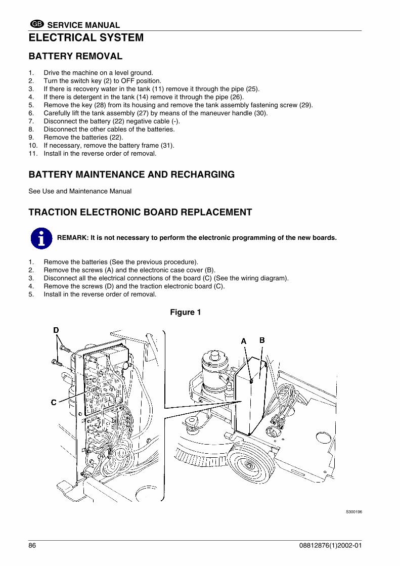
ELECTRICAL SYSTEMBATTERY REMOVAL
1. Drive the machine on a level ground.2. Turn the switch key (2) to OFF position.3. If there is recovery water in the tank (11) remove it through the pipe (25).4. If there is detergent in the tank (14) remove it through the pipe (26).5. Remove the key (28) from its housing and remove the tank assembly fastening screw (29).6. Carefully lift the tank assembly (27) by means of the maneuver handle (30). 7. Disconnect the battery (22) negative cable (-).8. Disconnect the other cables of the batteries.9. Remove the batteries (22).10. If necessary, remove the battery frame (31).11. Install in the reverse order of removal.
BATTERY MAINTENANCE AND RECHARGING
See Use and Maintenance Manual
TRACTION ELECTRONIC BOARD REPLACEMENT
1. Remove the batteries (See the previous procedure).2. Remove the screws (A) and the electronic case cover (B).3. Disconnect all the electrical connections of the board (C) (See the wiring diagram).4. Remove the screws (D) and the traction electronic board (C).5. Install in the reverse order of removal.
Figure 1
S300196
REMARK: It is not necessary to perform the electronic programming of the new boards.
86 08812876(1)2002-01

SERVICE MANUAL
ELECTRICAL SYSTEMGB
ELECTRICAL SYSTEMSERVICE ELECTRONIC BOARD REPLACEMENT
1. Remove the batteries (See the previous procedure).2. Remove the screws (A) and the electronic case cover (B).3. Disconnect all the electrical connections of the board (C) (See the wiring diagram).4. Disengage the retainers (D) and remove the service electronic board (C).5. Install in the reverse order of removal.
Figure 2
S300197
REMARK: It is not necessary to perform the electronic programming of the new board.
08812876(1)2002-01 87
SERVICE MANUAL
ELECTRICAL SYSTEMGB
TROUBLESHOOTING
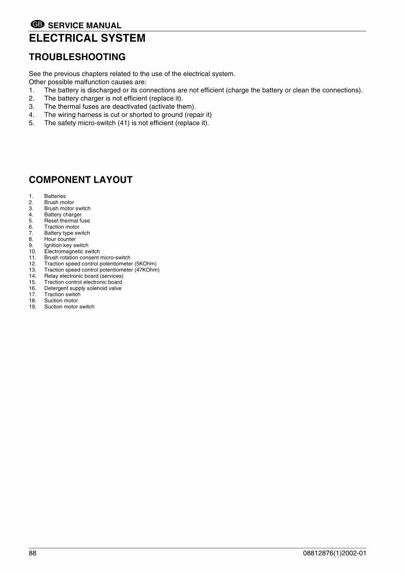
See the previous chapters related to the use of the electrical system.Other possible malfunction causes are:1. The battery is discharged or its connections are not efficient (charge the battery or clean the connections).2. The battery charger is not efficient (replace it).3. The thermal fuses are deactivated (activate them).4. The wiring harness is cut or shorted to ground (repair it)5. The safety micro-switch (41) is not efficient (replace it).
COMPONENT LAYOUT
1. Batteries2. Brush motor3. Brush motor switch4. Battery charger5. Reset thermal fuse6. Traction motor7. Battery type switch8. Hour counter9. Ignition key switch10. Electromagnetic switch11. Brush rotation consent micro-switch12. Traction speed control potentiometer (5KOhm)13. Traction speed control potentiometer (47KOhm)14. Relay electronic board (services)15. Traction control electronic board16. Detergent supply solenoid valve17. Traction switch18. Suction motor19. Suction motor switch
88 08812876(1)2002-01

SERVICE MANUAL
ELECTRICAL SYSTEMGB
Figure 3
S300198
08812876(1)2002-01 89

SERVICE MANUAL
ELECTRICAL SYSTEMGB
WIRING DIAGRAM BA 450/530 - after serial number 014106978With traction with battery charger08812796
S300199
90 08812876(1)2002-01

SERVICE MANUAL
ELECTRICAL SYSTEMGB
WIRING DIAGRAM BA 450/530 - after serial number 014106978Without traction with battery charger08812797
S300200
08812876(1)2002-01 91

SERVICE MANUAL
ELECTRICAL SYSTEMGB
WIRING DIAGRAM BA 450/530 - after serial number 014106978With traction without battery charger08812798
S300201
92 08812876(1)2002-01

SERVICE MANUAL
ELECTRICAL SYSTEMGB
WIRING DIAGRAM BA 450/530 - after serial number 014106978Without traction without battery charger08812799
S300202
08812876(1)2002-01 93
SERVICE MANUAL
ELECTRICAL SYSTEMGB
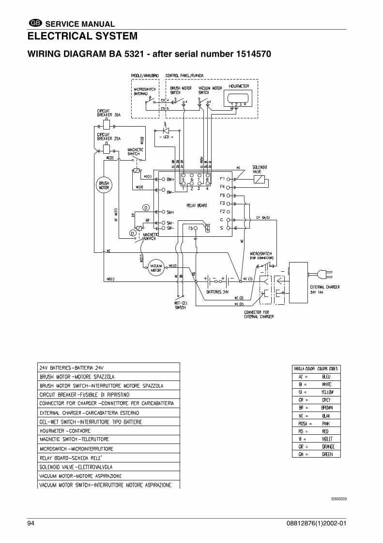
WIRING DIAGRAM BA 5321 - after serial number 1514570
S300203
94 08812876(1)2002-01

SERVICE MANUAL
ELECTRICAL SYSTEMGB
WIRING DIAGRAM BA 5321D - after serial number 1514570
S300204
08812876(1)2002-01 95

SERVICE MANUAL
ELECTRICAL SYSTEMGB
FINE
96 08812876(1)2002-01

Nilfisk-Advance, Inc.14600 21st Avenue NorthPlymouth, MN, 55447-3408www.nilfisk-advance.comPhone: 800-989-2235Fax: 800-989-6566
©2002 Nilfisk-Advance, Inc., Plymouth, MN 55447-3408Printed in the U.S.A.