ba 5321/d - ba 6124d · machine nomenclature 8 detergent supply system 10 detergent tank and supply...
TRANSCRIPT

BA 5321/D - BA 6124D
SERVICE MANUALAdvance Models:08838130 - 08838135 from serial number 1640309
08603992(1)2003-06
908 7014 020

Nilfisk-Advance, Inc.14600 21st Avenue NorthPlymouth, MN, 55447-3408www.nilfisk-advance.comPhone: 800-989-2235Fax: 800-989-6566
©2003 Nilfisk-Advance, Inc., Plymouth, MN 55447-3408Printed in Italy

SERVICE MANUAL GB
INDEX
GENERAL INFORMATION 3MACHINE LIFTING 3MACHINE TRANSPORTATION 3MACHINE PUSHING OR TOWING 3OTHER AVAILABLE MANUALS 3SAFETY - ACCIDENT PREVENTION 4
GENERAL SAFETY RULES 4TECHNICAL DATA 5MAINTENANCE 7
SCHEDULED MAINTENANCE 7MACHINE NOMENCLATURE 8
DETERGENT SUPPLY SYSTEM 10DETERGENT TANK AND SUPPLY SYSTEM CLEANING 10DETERGENT FILTER CLEANING 10SOLENOID VALVE AND DETERGENT FLOW TAP REPLACEMENT 11DETERGENT FLOW CABLE AND CONTROL LEVER REPLACEMENT 12TROUBLESHOOTING 13
SMALL AMOUNT OF THE DETERGENT OR NO DETERGENT REACHES THE BRUSH 13THE DETERGENT REACHES THE BRUSH ALSO WHEN THE MACHINE IS OFF 13
SWEEPING SYSTEM 14BRUSH MOTOR ELECTRICAL INPUT CHECK (BA 5321/D Only) 14BRUSH MOTOR ELECTRICAL INPUT CHECK (BA 6124D Only) 15BRUSH MOTOR REPLACEMENT (BA 5321/D Only) 17BRUSH MOTOR REPLACEMENT (BA 6124D Only) 19BRUSH MOTOR BRUSHES (OR CARBON BRUSHES) CHECK AND REPLACEMENT (BA 5321/D Only) 22BRUSH MOTOR BRUSHES (OR CARBON BRUSHES) CHECK AND REPLACEMENT (BA 6124D Only) 23BRUSH BELT CHECK (BA 6124D Only) 24BRUSH BELT REPLACEMENT AND HEAD BEARINGS CHECK (BA 6124D Only) 25BRUSH REDUCTION UNIT REPLACEMENT (BA 5321/D Only) 28BRUSH ROTATION CONSENT MICRO-SWITCH ADJUSTMENT 33TROUBLESHOOTING 34
OPEN CIRCUIT 34THE BRUSH DOES NOT ROTATE 34
RECOVERY SYSTEM 35FLOAT SHIELD AND SUCTION PRE-FILTER CLEANING 35SUCTION PRE-FILTER ASSEMBLY REPLACEMENT 36TANK COVER GASKET AND COMPENSATION HOLE CHECK 37SUCTION MOTOR ELECTRICAL INPUT CHECK 38SUCTION MOTOR REMOVAL 39SUCTION MOTOR BRUSH/CARBON BRUSH CHECK AND REPLACEMENT 40SUCTION MOTOR BRUSH/CARBON BRUSH CHECK AND REPLACEMENT 41RECOVERY WATER DRAIN PIPE REMOVAL 42PULIZIA/CONTROLLO VENTOSA DI ASPIRAZIONE ED EVENTUALE SOSTITUZIONE DEI FLAP 43
SUCTION CAP CHECK/CLEANING AND POSSIBLE FLAPS REPLACEMENT 44SUCTION CAP REMOVAL 44
RECOVERY SYSTEM 45TROUBLESHOOTING 45
DIRTY WATER SUCTION IS INSUFFICIENT OR THERE IS NO SUCTION 45THE SUCTION CAP LEAVES LINING OR DOES NOT COLLECT WATER 45
08603992(1)2003-06 1
SERVICE MANUALGB
TRACTION SYSTEM 46DRIVE MOTOR ELECTRICAL INPUT CHECK 46DRIVE MOTOR REMOVAL 48DRIVE MOTOR BRUSH (OR CARBON BRUSH) CHECK AND REPLACEMENT 50POTENTIOMETER ADJUSTMENT 52TROUBLESHOOTING 53
OPEN CIRCUIT 53THE MACHINE DOES NOT MOVE 53
ELECTRICAL SYSTEM 54BATTERY REMOVAL 54BATTERY MAINTENANCE AND RECHARGING 54TRACTION ELECTRONIC BOARD REPLACEMENT 54SERVICE ELECTRONIC BOARD REPLACEMENT 55ELECTRONIC BOARD CONTROLLING THE BRUSH MOTOR OPERATION CHECK AND REPLACEMENT (BA 6124D Only)) 56TROUBLESHOOTING 58COMPONENT LAYOUT 58BA 5321 WIRING DIAGRAM 60WIRING DIAGRAM BA 5321D 61WIRING DIAGRAM BA 6124D 62
2 08603992(1)2003-06

SERVICE MANUAL
GENERAL INFORMATIONGB
GENERAL INFORMATIONMACHINE LIFTING
MACHINE TRANSPORTATION
MACHINE PUSHING OR TOWING
OTHER AVAILABLE MANUALS
The following manuals are available by Advance Literature Service Department:– BA 5321/D - BA 6124D Part List – Form Number 08812649– BA 5321/D - BA 6124D Instructions for Use - Form Number 08812648
WARNING !Do not work under the lifted machine, if it is not securely fixed.
WARNING !Before transporting the machine, ensure that:
• All doors and carters are closed• The ignition key is not inserted• The machine is fastened to the mean of transportation
WARNING !Do not move the machine by pushing or towing it, unless you follow the procedures describedin the Use and Maintenance Manual. If you do not follow the specified procedures the machinecan be damaged.
08603992(1)2003-06 3

SERVICE MANUAL
GENERAL INFORMATIONGB
SAFETY - ACCIDENT PREVENTION
Advance uses the following symbols to indicate potentially dangerous situations. Always read carefully thisinformation and take the necessary precautions to protect people and objects.
GENERAL SAFETY RULES
Specific warnings and cautions to inform about potential damages to people and machine are shown below.
DANGER !Indicates the risk of being injured or the risk of death.
WARNING !Indicates the risk of being injured.
CAUTION !Indicates the risk of light injuries to people, machine or other objects.
WARNING !Drive the machine on a level ground; to perform maintenance/repair procedures turn themachine ignition key to OFF position and disconnect the battery.This machine must be used by qualified and authorized personnel only.Keep the battery far from sparks, flames and smoke. During the normal operation explosivegases are delivered.Do not wear jewels when working near electrical components.Do not work under the lifted machine, if it is not securely fixed.Do not operate the machine near inflammable liquids or vapors.
CAUTION !Carefully read all maintenance/repair instructions before performing any maintenance/repairprocedure.Take all necessary precautions to prevent hair, jewels and loose clothes from being caught bythe machine moving parts.Battery charging produces explosive hydrogen gas. Charge the batteries only in well-ventilatedareas and far from naked flames.Do not smoke during battery charging.Do not leave the machine unattended on slopes with the ignition key still inserted. Do not use the machine on slopes with an inclination higher than 2%.Do not wash the machine with pressurized water.Do not use the machine in too dusty areas.This machine is not suitable for collecting dangerous powders.Take care when the machine gets under the freezing temperature, because the water inside tanksand pipes can freeze.While using this machine, take care not to cause damage to people and children especially.This machine cannot be used on public roads.
4 08603992(1)2003-06

SERVICE MANUAL
GENERAL INFORMATIONGB
TECHNICAL DATA
Dimensions
BA 5321/D - BA 6124D BA 5321/D BA 6124DSuction width 770 mm (30 in) 812 mm (32 in)Sweeping width 530 mm (20.8 in) 610 mm (24 in)Machine length 1330 mm (52 in) 1311 mm (51.61 in)Machine height at the maneuverhandle 1078.5 mm (42.5 in) 1078 mm (42.4 in)Brush dimension ø 530 mm (20.8 in) ø 305 mm (12 in)Brush speed 180 RPM 220 RPMBrush pressure on the floor 27 kg (60 lbs) 35.5 kg (78 lbs)Forward maximum speed (*) 4.5 km/h (2.8 mph) (*) 4.5 km/h (2.8 mph)Detergent tank capacity 55 liters (13.2 gal) 55 liters (13.2 gal)Recovery water tank capacity 55 liters (13.2 gal) 55 liters (13.2 gal)Machine weight (without batteries) 134 kg (296 lbs) 150 kg (330 lbs)
Batteries
Standard batteries (no. 2 batteries) 12 Volt, 100 Ah 12 Volt, 100 Ah
General technical characteristics
Electrical system voltage 24 V 24 VBrush motor 650 W 650 W Suction motor 500 W 500 W Drive motor (*) 200 W (*) 200 W Dirty water suction pressure 13 kPa (56.9 in/water) 13 kPa (56.9 in/water)
(*) for BA 5321D
08603992(1)2003-06 5

SERVICE MANUAL
GENERAL INFORMATIONGB
S300455Size in mm
998
560,
5
770
1330
1078
.581
2
634
1311
998
1078
BA 5321/D
BA 6124D
6 08603992(1)2003-06

SERVICE MANUAL
GENERAL INFORMATIONGB
MAINTENANCE
SCHEDULED MAINTENANCE
The machine proper and safe operation is granted by a careful and constant maintenance.
The following table sums up the scheduled maintenance. The indicated periods can be subjected to variationsaccording to working conditions. These must be defined by the person in charge of maintenance.For maintenance operation instructions see the following paragraphs.
See GENERAL INFORMATION and SAFETY - ACCIDENT PREVENTION
Maintenance operation On deliveryAfter use
(daily)
Every 25 hours (or weekly)
Every 100 hours
Every 200 hours
Charge the battery •Battery liquid level and voltage (Volt) • •
Suction cap cleaning/check •Float shield and suction pre-filter cleaning •
Tank cover gasket check (vacuum chamber) •
Detergent tank and supply system cleaning •
Detergent filter cleaning •Ispezione ai serbatoi e ai tubi flessibili •
Hose and tank inspection •Electric suction motor brush (or carbon brush) check and replacement
•
Electric drive motor brush (or carbon brush) check and replacement
•
Electric brush rotation motor brush (or carbon brush) check and replacement
•
Brush rotation toothed belt check •
08603992(1)2003-06 7

SERVICE MANUAL
GENERAL INFORMATIONGB
MACHINE NOMENCLATURE
In this Manual you find numbers in brackets – example: (2). These numbers refer to the components indicated inthese two nomenclature pages. Refer to these pages each time you want to find the component mentioned in thetext.
1. Speed control potentiometer (*) 26. Detergent drain pipe
2. Main key switch (*)3. Brush switch4. Suction switch5. Battery condition indicator6. Detergent flow control lever7. Hour counter8. Start/Stop drive panel9. Squeegee lifting/lowering handle10. Brush lifting/lowering pedal11. Water recovery tank12. Recovery tank automatic float shut-off13. Suction pre-filter14. Detergent tank15. Suction motor16. Brush motor17. Traction adjusting handles (BA 5321/D only)18. Brush (BA 5321/D)19. Integrated battery charger 20. Circuit panel21. Drive motor (*)22. Batteries23. Squeegee assembly24. Tank covers25. Recovery water drain pipe8
27. Tank assembly28. Key (supplied with the machine)29. Tank assembly fastening screw30. Machine maneuver handle31. Battery frame32. Front wheel33. Driving wheels (*)34. Drive motor thermal fuse35. Brush motor thermal fuse36. Suction motor thermal fuse37. Brush reduction unit (BA 5321/D)38. Suction cap balancing adjustment handwheel39. Traction switch (*)40. Acoustic insulation assembly41. Brushes (BA 6124D only)42. Brush motor electronic board and protective cover (BA 6124D
only)43. Inspection cover for brush rotation belt (BA 6124D only)44. Brush release push-button (BA 6124D only)45. Splash-shield (BA 6124D only)46. Commutator for WET or GEL batteries47. Electrical connection to the network, during battery recharging
(version with battery charger installed on the machine)
(*) BA 5321D / BA 6124D
S300456
08603992(1)2003-06

SERVICE MANUAL
GENERAL INFORMATIONGB
08603992(1)2003-06 9
MACHINE NOMENCLATURE (CONTINUES)
S300163

SERVICE MANUAL
DETERGENT SUPPLY SYSTEMGB
DETERGENT SUPPLY SYSTEMDETERGENT TANK AND SUPPLY SYSTEM CLEANING1. Empty the detergent tank (14) through the pipe (26).2. Take the detergent flow control lever (6) in wide-open position, then activate the machine until the detergent
inside the machine is exhausted.3. Carry out the Detergent filter cleaning (see the following procedure).
DETERGENT FILTER CLEANING1. Drive the machine on a level ground.2. Turn the switch key (2) to OFF position.3. Operating on the right lower side of the machine, close the detergent tap (E). The tap (E) is closed when it is
located at position (F) as to the pipeline; it is open when it is located at position (G).4. Operating on the left lower side of the machine, remove the cover (A) and the wire gauze (B), clean and install
them again on the related support (C).
5. Carry out steps from 1. to 3. in the reverse order.
Figure 1
S300420
REMARK: The wire gauze (B) must be correctly positioned on the support (C) housing (D).
10 08603992(1)2003-06

SERVICE MANUAL
DETERGENT SUPPLY SYSTEMGB
SOLENOID VALVE AND DETERGENT FLOW TAP REPLACEMENT
1. Drive the machine on a level ground.2. Turn the switch key (2) to OFF position.3. If there is recovery water in the tank (11) remove it through the pipe (25).4. If there is detergent in the tank (14) remove it through the pipe (26).5. Remove the supplied key (28) from its housing and unscrew the tank assembly fastening screw (29).6. Carefully lift the tank assembly (27) by means of the maneuver handle (30).7. Disconnect the battery (22) negative cable (-).8. Disconnect the other cables of the batteries.9. Remove the batteries (22).10. Remove the battery frame (31).11. Remove the screws (A) and the cover (B) of the electronic case, then disconnect the solenoid valve (D)
cables (C) from the electronic board connections (E) (connection electrical symbols: F1 e F4).12. Disconnect the hoses (F and G).13. Remove the solenoid valve (D) fastening screws (H).14. Disconnect the lever (L) control cable (I) of the tap (M). If necessary loosen the cable sheath (O) fixing clamp
(N).
15. Remove the solenoid valve assembly (D) with the tap (M).16. Remove the pipe unions (Q and S) at the cabinet bench.17. Remove the tap (M) from the solenoid valve (D).
18. Install in the reverse order of removal.
Figure 2
S300421
REMARK: When reinstalling, fix the sheath (O) by means of the clamp (N) in the same position(see the print on the sheath); in this way the adjustment of the tap control remains unchanged.
REMARK: when reinstalling the solenoid valve (D), the stamping orientation (T) must be asshown in the figure; moreover, before installing the unions (Q and S) and the tap (M) clean therelated threads and apply LOCTITE 572 sealant.
08603992(1)2003-06 11

SERVICE MANUAL
DETERGENT SUPPLY SYSTEMGB
DETERGENT FLOW CABLE AND CONTROL LEVER REPLACEMENT1. Drive the machine on a level ground.2. Turn the switch key (2) to OFF position.3. Operating under the machine left side, loosen the sheath (D) fixing clamp (C) and disconnect the cable (A)
from the tap lever (B).4. Disconnect the sheath (D) from the fixing clamps along its run up to the lever (6).5. Remove the handgrip (F) from the lever (G).6. Remove the screws (H) and lightly slide the panel (I).7. Remove the screws (L) and the control lever with the cable (M).8. Install in the reverse order of removal and adjust the sheath terminal (D) position so that when the tap lever
(B) is in the position shown in the figure (closed) the control lever (G) is in “zero” flow position. When thelever (G) is in maximum flow position, the lever (B) rotates about 90°.
Figure 3
S300166
Figure 4
S300167
12 08603992(1)2003-06

SERVICE MANUAL
DETERGENT SUPPLY SYSTEMGB
TROUBLESHOOTING
SMALL AMOUNT OF THE DETERGENT OR NO DETERGENT REACHES THE BRUSH
Possible cause:1. The brush switch (3) is not in ON position or it is broken (position it to ON or repair/replace it). 2. The detergent filter is obstructed/dirty (clean it).3. The detergent flow control lever does not control the related tap anymore (check the control lever cable, from
the lever to the tap).4. The detergent tap is stuck closed (replace the tap).5. The solenoid valve is broken or there is an open in the electrical connection (replace the solenoid valve/repair
the electrical connection).6. The service electronic board is broken (replace it)7. There is debris in the detergent tank obstructing the output hole (clean the tank).8. There is debris in the detergent pipeline obstructing the detergent flow (clean the pipeline).
THE DETERGENT REACHES THE BRUSH ALSO WHEN THE MACHINE IS OFF
Possible cause:1. The solenoid valve is broken (replace it).
08603992(1)2003-06 13

SERVICE MANUAL
SWEEPING SYSTEMGB
SWEEPING SYSTEMBRUSH MOTOR ELECTRICAL INPUT CHECK (BA 5321/D Only)
1. Remove the brush (18).2. Drive the machine on a level ground.3. Turn the switch key (2) to OFF position.4. If there is recovery water in the tank (11) remove it through the pipe (25).5. If there is detergent in the tank (14) remove it through the pipe (26).6. Remove the supplied key (28) from its housing and unscrew the tank assembly fastening screw (29).7. To operate on the brush motor (16) carefully lift the tank assembly (27) by means of the maneuver handle
(30).8. Disconnect the battery (22) negative cable (-).9. Disconnect the motor electrical cables (A) from the connection (B)..
10. Connect the brush motor to the machine battery, as described in the underlying diagram, inserting the 30 Afuse (D), for safety’s sake.
11. With an ammeter (C) check that the brush motor input is 8 I 9 A at 24V..If the electrical input is higher, perform the following operations to detect and correct the causes:– (AMER motor only) perform the motor brushes check (see the procedure on the following page)– if necessary, disassemble the motor (see the procedure on the following pages) and check all its parts.If the above-mentioned procedures do not lead to a correct electrical input, it is necessary to replace themotor (see the procedure on the following pages).
12. Carry out steps from 1. to 9. in the reverse order.
WARNING! This procedure must be performed by qualified personnel only.
REMARK: the motor installed on the machine can either be a BOSCH (shown in the figure below) or a AMER;the following procedure refers to both types of motors, unless otherwise specified.
WARNING! Pay attention to the brush flange rotation while performing the following steps.
Figure 2
Figure 1S300168
14
S300169
C
D
30A
08603992(1)2003-06
SERVICE MANUAL
SWEEPING SYSTEMGB
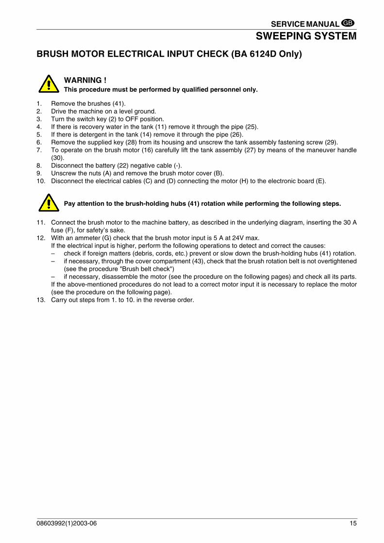
BRUSH MOTOR ELECTRICAL INPUT CHECK (BA 6124D Only)
1. Remove the brushes (41).2. Drive the machine on a level ground.3. Turn the switch key (2) to OFF position.4. If there is recovery water in the tank (11) remove it through the pipe (25).5. If there is detergent in the tank (14) remove it through the pipe (26).6. Remove the supplied key (28) from its housing and unscrew the tank assembly fastening screw (29).7. To operate on the brush motor (16) carefully lift the tank assembly (27) by means of the maneuver handle
(30).8. Disconnect the battery (22) negative cable (-).9. Unscrew the nuts (A) and remove the brush motor cover (B).10. Disconnect the electrical cables (C) and (D) connecting the motor (H) to the electronic board (E).
11. Connect the brush motor to the machine battery, as described in the underlying diagram, inserting the 30 Afuse (F), for safety’s sake.
12. With an ammeter (G) check that the brush motor input is 5 A at 24V max.If the electrical input is higher, perform the following operations to detect and correct the causes:– check if foreign matters (debris, cords, etc.) prevent or slow down the brush-holding hubs (41) rotation.– if necessary, through the cover compartment (43), check that the brush rotation belt is not overtightened
(see the procedure "Brush belt check")– if necessary, disassemble the motor (see the procedure on the following pages) and check all its parts.If the above-mentioned procedures do not lead to a correct motor input it is necessary to replace the motor(see the procedure on the following page).
13. Carry out steps from 1. to 10. in the reverse order.
WARNING ! This procedure must be performed by qualified personnel only.
Pay attention to the brush-holding hubs (41) rotation while performing the following steps.
08603992(1)2003-06 15

SERVICE MANUAL
SWEEPING SYSTEMGB
BRUSH MOTOR ELECTRICAL INPUT CHECK (BA 6124D Only) (Continues)
Figure 3
S300457
Figure 4
S300423
G
F
30A
16 08603992(1)2003-06

SERVICE MANUAL
SWEEPING SYSTEMGB
BRUSH MOTOR REPLACEMENT (BA 5321/D Only)
1. Remove the brush (18).2. Drive the machine on a level ground.3. Turn the switch key (2) to OFF position.4. If there is recovery water in the tank (11) remove it through the pipe (25).5. If there is detergent in the tank (14) remove it through the pipe (26).6. Remove the supplied key (28) from its housing and unscrew the tank assembly fastening screw (29).7. To operate on the brush motor (16) carefully lift the tank assembly (27) by means of the maneuver handle
(30).8. Disconnect the battery (22) negative cable (-).9. Disconnect the motor electrical cables (A) from the connection (B).10. Cut the clamp (C).11. Remove the nuts (D) and the brush motor (E).12. Remove the spring pin (F) and the pinion (G) at the cabinet bench.13. Remove the bearing (H) and the gasket (I).
14. Remove the wire gauze (L).15. Install in the reverse order of removal.
REMARK: the motor installed on the machine can either be a BOSCH or a AMER.The following procedure refers to the BOSCH motor only.
CAUTION!When reinstalling, take care to assemble the bearing (H) with the smaller side (M) facing thepinion (as shown in the figure).
Figure 5
S300170
08603992(1)2003-06
Figure 6
S300171
17

SERVICE MANUAL
SWEEPING SYSTEMGB
BRUSH MOTOR REPLACEMENT (BA 5321/D Only)
1. Remove the brush (18).2. Drive the machine on a level ground.3. Turn the switch key (2) to OFF position.4. If there is recovery water in the tank (11) remove it through the pipe (25).5. If there is detergent in the tank (14) remove it through the pipe (26).6. Remove the supplied key (28) from its housing and unscrew the tank assembly fastening screw (29).7. To operate on the brush motor (16) carefully lift the tank assembly (27) by means of the maneuver handle
(30).8. Disconnect the battery (22) negative cable (-).9. Disconnect the motor electrical cables (A) from the connection (B).10. Cut the clamp (C).11. Unscrew the nuts (D).12. Carefully lift and remove the brush motor (E) with its pinion and bearing.
13. Install in the reverse order of removal, with the following change:– if applied at step 12, remember to remove the adhesive tape.
Figure 7
S300424
REMARK: the motor installed on the machine can either be a BOSCH or a AMER.The following procedure refers to the AMER motor only.
CAUTION!To prevent part (F) and part (G) from separating during the motor disassembly/reassembly, it isadvisable to apply adhesive tape temporarily to keep the two parts together.
18 08603992(1)2003-06

SERVICE MANUAL
SWEEPING SYSTEMGB
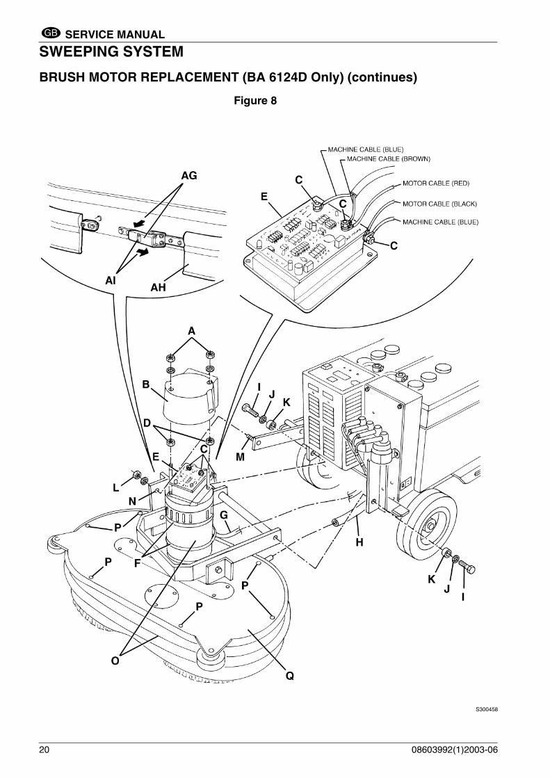
BRUSH MOTOR REPLACEMENT (BA 6124D Only)
1. Remove the brushes (41).2. Drive the machine on a level ground.3. Turn the switch key (2) to OFF position.4. If there is recovery water in the tank (11) remove it through the pipe (25).5. If there is detergent in the tank (14) remove it through the pipe (26).6. Remove the supplied key (28) from its housing and unscrew the tank assembly fastening screw (29).7. To operate on the brush motor (16) carefully lift the tank assembly (27) by means of the maneuver handle
(30).8. Disconnect the battery (22) negative cable (-).9. Unscrew the nuts (A) and remove the brush motor cover (B).10. Disconnect the power cables from the connections (C) to the motor electronic board (E). 11. Cut the clamps (F) and disengage the motor cable (G).12. Unscrew the nuts (D) and remove the electronic board (E).13. Disengage the retaining spring (AI) and open the hook (AG), then remove the splash-shield (AH).14. Disconnect the detergent pipe (H).15. On both sides of the machines, loosen the screws (I) and recover the washers (J) and spacers (K).16. Loosen the nut (L).17. By means of a screw-driver, disengage the threaded pin (M) from the hole (N).18. Recover the brush head assembly (O) and take it to the cabinet bench.19. Remove the screws (P) and the cover (Q).20. Remove the screws (R) and (S) then remove the motor assembly with the flange (T).
21. Loosen the screws (W) and remove the flange (X) and the motor (Y) with its pinion.22. Loosen the screw (Z) and remove the pinion (AA), then recover the relative key. 23. Before reinstalling the motor, inspect the brush rotation belt (V) condition (see the related paragraph for the
procedure).24. Install in the reverse order of removal, with the following change:
– when reinstalling the motor (Y) onto the flange (X) position the motor so that the electrical cable (AB) isplaced as to the flange as shown in the figure below.
CAUTION!The belt (V) adjusting nut (U) is factory set and sealed by the Manufacturer.No adjustment of the belt (V) through the nut (U) is required from the user.
08603992(1)2003-06 19
SERVICE MANUAL
SWEEPING SYSTEMGB
BRUSH MOTOR REPLACEMENT (BA 6124D Only) (continues)
Figure 8
S300458
20 08603992(1)2003-06

SERVICE MANUAL
SWEEPING SYSTEMGB
BRUSH MOTOR REPLACEMENT (BA 6124D Only) (continues)Figure 9
S300426
Figure 10
S300427
08603992(1)2003-06 21
SERVICE MANUAL
SWEEPING SYSTEMGB
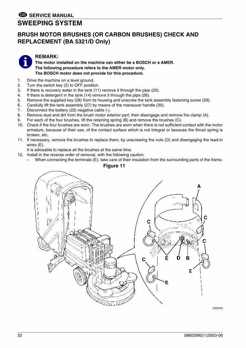
BRUSH MOTOR BRUSHES (OR CARBON BRUSHES) CHECK AND REPLACEMENT (BA 5321/D Only)
1. Drive the machine on a level ground.2. Turn the switch key (2) to OFF position.3. If there is recovery water in the tank (11) remove it through the pipe (25).4. If there is detergent in the tank (14) remove it through the pipe (26).5. Remove the supplied key (28) from its housing and unscrew the tank assembly fastening screw (29).6. Carefully lift the tank assembly (27) by means of the maneuver handle (30). 7. Disconnect the battery (22) negative cable (-).8. Remove dust and dirt from the brush motor exterior part; then disengage and remove the clamp (A).9. For each of the four brushes, lift the retaining spring (B) and remove the brushes (C).10. Check if the four brushes are worn. The brushes are worn when there is not sufficient contact with the motor
armature, because of their use, of the contact surface which is not integral or because the thrust spring isbroken, etc.
11. If necessary, remove the brushes to replace them, by unscrewing the nuts (D) and disengaging the lead-inwires (E).It is advisable to replace all the brushes at the same time.
12. Install in the reverse order of removal, with the following caution:– When connecting the terminals (E), take care of their insulation from the surrounding parts of the frame.
Figure 11
S300459
REMARK: The motor installed on the machine can either be a BOSCH or a AMER.The following procedure refers to the AMER motor only.The BOSCH motor does not provide for this procedure.
22 08603992(1)2003-06

SERVICE MANUAL
SWEEPING SYSTEMGB
BRUSH MOTOR BRUSHES (OR CARBON BRUSHES) CHECK AND REPLACEMENT (BA 6124D Only)
1. Drive the machine on a level ground.2. Turn the switch key (2) to OFF position.3. If there is recovery water in the tank (11) remove it through the pipe (25).4. If there is detergent in the tank (14) remove it through the pipe (26).5. Remove the supplied key (28) from its housing and unscrew the tank assembly fastening screw (29).6. Carefully lift the tank assembly (27) by means of the maneuver handle (30). 7. Disconnect the battery (22) negative cable (-).8. Remove dust and dirt from the brush motor exterior part; then disengage and remove the clamp (A).9. For each of the four brushes, lift the retaining spring (B) and remove the brushes (C).10. Check if the four brushes are worn. The brushes are worn when there is not sufficient contact with the motor
armature, because of their use, of the contact surface which is not integral or because the thrust spring isbroken, etc.
11. If necessary, remove the brushes to replace them, by unscrewing the nuts (D) and disengaging the lead-inwires (E).It is advisable to replace all the brushes at the same time.
12. Install in the reverse order of removal, with the following caution:– When connecting the terminals (E), take care of their insulation from the surrounding parts of the frame.
Figure 12
S300460
08603992(1)2003-06 23

SERVICE MANUAL
SWEEPING SYSTEMGB
BRUSH BELT CHECK (BA 6124D Only)
1. Drive the machine on a level ground.2. Turn the switch key (2) to OFF position.3. If there is recovery water in the tank (11) remove it through the pipe (25).4. If there is detergent in the tank (14) remove it through the pipe (26).5. Remove the supplied key (28) from its housing and unscrew the tank assembly fastening screw (29).6. Carefully lift the tank assembly (27) by means of the maneuver handle (30). 7. Disconnect the battery (22) negative cable (-).8. Remove the screws (A) and the cover (B).9. Check the brush belt (C) for integrity; check the belt completely on its whole length and turn it by one full turn,
by manually operating the left brush (D).If the belt is damaged it must be replaced (see the procedure on the following pages).
10. Install in the reverse order of removal.
Figure 13
S300461
CAUTION!The belt (C) adjusting nut (E) is factory set and sealed by the Manufacturer.No further adjustment of the belt (C) is required from the user; in case tensioning problemsshould arise, the belt must be replaced.
24 08603992(1)2003-06

SERVICE MANUAL
SWEEPING SYSTEMGB
BRUSH BELT REPLACEMENT AND HEAD BEARINGS CHECK (BA 6124D Only)
1. Drive the machine on a level ground.2. Turn the switch key (2) to OFF position.3. If there is recovery water in the tank (11) remove it through the pipe (25).4. If there is detergent in the tank (14) remove it through the pipe (26).5. Remove the supplied key (28) from its housing and unscrew the tank assembly fastening screw (29).6. Carefully lift the tank assembly (27) by means of the maneuver handle (30). 7. Disconnect the battery (22) negative cable (-).8. Unscrew the nuts (A) and remove the brush motor cover (B).9. Disconnect the power cables from the connections (C) to the motor electronic board (D). 10. Cut the clamps (E) and disengage the motor cable (F).11. Disengage the retaining spring (AF) and open the hook (AD), then remove the splash-shield (AE).12. Disconnect the detergent pipe (G).13. On both sides of the machines, loosen the screws (H) and recover the washers (I) and spacers (L).14. Loosen the nut (M).15. By means of a screw-driver, disengage the threaded pin (N) from the hole (O).16. Recover the brush head assembly (P) and take it to the cabinet bench.17. Remove the screws (Q) and the cover (R).18. Remove the screws (S) and (T) then remove the motor assembly with the flange (U).19. Remove the belt (Z).
20. Before reinstalling the new belt (Z):– clean thouroughly the inner part (AB) of the head– check that the rotation bearings (AA) of the pulleys rotate freely, without noise or excessive backlash.Se necessario sostituirli; vedere il Part List per le sequenze di smontaggio delle parti interessate.
21. Insert the new belt (Z) into its housing.22. Install in the reverse order of removal.
CAUTION! The belt (Z) adjusting nut (X) is factory set and sealed by the Manufacturer.No adjustment of the belt (Z) through the nut (X) is required from the user.
08603992(1)2003-06 25

SERVICE MANUAL
SWEEPING SYSTEMGB
BRUSH BELT REPLACEMENT AND HEAD BEARINGS CHECK (BA 6124D Only) (Continues)
Figure 14
S300462
26 08603992(1)2003-06

SERVICE MANUAL
SWEEPING SYSTEMGB
BRUSH BELT REPLACEMENT AND HEAD BEARINGS CHECK (BA 6124D Only) (Continues)
Figure 15
S300432
Figure 16
S300432
08603992(1)2003-06 27

SERVICE MANUAL
SWEEPING SYSTEMGB
BRUSH REDUCTION UNIT REPLACEMENT (BA 5321/D Only)
1. Remove the brush (18).2. Drive the machine on a level ground.3. Turn the switch key (2) to OFF position.4. If there is recovery water in the tank (11) remove it through the pipe (25).5. If there is detergent in the tank (14) remove it through the pipe (26).6. Remove the supplied key (28) from its housing and unscrew the tank assembly fastening screw (29).7. Carefully lift the tank assembly (27) by means of the maneuver handle (30). 8. Disconnect the battery (22) negative cable (-).9. Carefully lower the tank assembly (27) by means of the maneuver handle (30).10. Lift the machine by means of a lifting system, if available, in order to work under the brush-holder (18); if the
lifting system is not available, lay down the machine on one side and perform the following procedure:– Remove the suction cap (see the related paragraph).– Carefully lift the tank assembly (27) by means of the maneuver handle (30). – Disconnect and remove the batteries (22).– Remove the battery frame (31).– Perform the following steps from 11. to 13. before laying down the machine.– Carefully lower the tank assembly (27) by means of the maneuver handle (30).– Lay down the machine on one side and set it down carefully on proper guards (E).– Carefully open the tank assembly (27) completely by means of the maneuver handle (30).
11. Disconnect the detergent pipe (A).12. Disconnect the motor electrical cables (B) from the connection (C).13. Cut the clamp (D).14. Operating on the brush installation area, remove the screw (G), the flange assembly (H) and recover the key
(I).15. Remove the screws (L) and the reduction unit with the motor (M).16. Remove the detergent pipe fixed on the holes (N).17. Remove the three nuts (O) and separate the brush motor (P) from the reduction unit (Q).18. Install in the reverse order of removal..
REMARK: The motor installed on the machine can either be a BOSCH or a AMER. The following procedurerefers to the BOSCH motor only.
CAUTION!Before installing the new reduction unit, fill in with oil of the type and quantity indicated by thereduction unit data plate.
Figure 18
Figure 17S300172
28
08603992(1)2003-06S300173

SERVICE MANUAL
SWEEPING SYSTEMGB
BRUSH REDUCTION UNIT REPLACEMENT (BA 5321/D Only) (Continues)
Figure 19
S300463
08603992(1)2003-06 29

SERVICE MANUAL
SWEEPING SYSTEMGB
BRUSH REDUCTION UNIT REPLACEMENT (BA 5321D Only)
1. Remove the brush (18).2. Drive the machine on a level ground.3. Turn the switch key (2) to OFF position.4. If there is recovery water in the tank (11) remove it through the pipe (25).5. If there is detergent in the tank (14) remove it through the pipe (26).6. Remove the supplied key (28) from its housing and unscrew the tank assembly fastening screw (29).7. Carefully lift the tank assembly (27) by means of the maneuver handle (30). 8. Disconnect the battery (22) negative cable (-).9. Carefully lower the tank assembly (27) by means of the maneuver handle (30).10. Lift the machine by means of a lifting system, if available, in order to work under the brush-holder (18); if the
lifting system is not available, lay down the machine on one side and perform the following procedure:– Remove the suction cap (see the related paragraph).– Carefully lift the tank assembly (27) by means of the maneuver handle (30). – Disconnect and remove the batteries (22).– Remove the battery frame (31).– Perform the following steps from 11. to 13. before laying down the machine.– Carefully lower the tank assembly (27) by means of the maneuver handle (30).– Lay down the machine on one side and set it down carefully on proper guards (E).– Carefully open the tank assembly (27) completely by means of the maneuver handle (30).
11. Disconnect the detergent pipe (A).12. Disconnect the motor electrical cables (B) from the connection (C).13. Cut the clamp (D).14. Operating on the brush installation area, remove the screw (G), the flange assembly (H) and recover the key
(I).15. Remove the screws (L) and the reduction unit with the motor (M).16. Remove the detergent pipe (N).17. Unscrew the motor mounting nuts (O) to the reduction unit.18. Carefully lift and remove the motor (P) with its pinion and bearing.
19. Recover the reduction unit with oil (Q).20. Install in the reverse order of removal, with the following change:
– before installing the new reduction unit, fill in with oil of the type and quantity indicated by the reductionunit data plate (SAE W 80 - 90 oil). The oil in the tank must cover the gear (W).
– if applied at step 18, remember to remove the adhesive tape.
REMARK: The motor installed on the machine can either be a BOSCH or a AMER.The following procedure refers to the AMER motor only.
CAUTION!to prevent part (T) and part (U) from separating during the motor disassembly/reassembly, it isadvisable to apply adhesive tape temporarily to keep the two parts together.
30 08603992(1)2003-06

SERVICE MANUAL
SWEEPING SYSTEMGB
BRUSH REDUCTION UNIT REPLACEMENT (BA 5321/D Only) (Continues)
Figure 20
S300435
Figure 21
S300173
08603992(1)2003-06 31

SERVICE MANUAL
SWEEPING SYSTEMGB
BRUSH REDUCTION UNIT REPLACEMENT BA 5321/D Only) (Continues)Figure 22
S300464
32 08603992(1)2003-06

SERVICE MANUAL
SWEEPING SYSTEMGB
BRUSH ROTATION CONSENT MICRO-SWITCH ADJUSTMENT1. Drive the machine on a level ground.2. Turn the switch key (2) to OFF position.3. If there is recovery water in the tank (11) remove it through the pipe (25).4. If there is detergent in the tank (14) remove it through the pipe (26).5. Remove the supplied key (28) from its housing and unscrew the tank assembly fastening screw (29).6. Carefully lift the tank assembly (27) by means of the maneuver handle (30).7. Disconnect the battery (22) negative cable (-).8. Carefully lower the tank assembly (27) by means of the maneuver handle (30).9. Remove the screws (A) and the drive panel (C) cover (B).10. With the drive panel (C) deactivated, check that the micro-switch (E) actuator (D) is in the cam (I) housing (F).11. Activate the panel (C) and check that the actuator (D) is at the positions (G and H) and activates the
micro-switch (E) (a “click” must be heard).If necessary, reach the required condition by loosening the screws (L) and adjusting the cam position (I)and/or loosening the screws (M) and adjusting the micro-switch position (E). Tighten the screws..
12. Install in the reverse order of removal.13. Carry out some tests to check the brush rotation consent.
Figure 23
S300175
Figure 24
S300176
CAUTION! If the micro-switch electrical connections (N) have been disconnected, take care to connect themagain correctly.
08603992(1)2003-06 33

SERVICE MANUAL
SWEEPING SYSTEMGB
TROUBLESHOOTING
OPEN CIRCUIT
The thermal fuse (35) determines the open circuit. This system allows to prevent the brush motor circuits frombeing damaged under overload conditions.If there is an open in the electrical circuit, the possible causes are the following.
Brush motor; the thermal fuse (35) activates and opens the electrical circuit.
Possible cause: 1. Bulky debris or cords around the brush or between the brush and its flange (remove the brush and the debris
or cords).2. The brush motor electrical input is too high (check the electrical input).Wait at least 2 minutes after the break and, when the problem is solved, push the thermal fuse button (35).
THE BRUSH DOES NOT ROTATE
Possible cause:1. To avoid damaging the floor, the brush motor turns off automatically when the machine stands still in the
same position (the brush cannot stand still in the same position).2. The battery voltage is too low (charge the battery).3. The electrical motor brushes are worn (replace the electrical motor brushes).4. Malfunction in the electrical motor (repair or replace the electrical motor).5. The thermal fuse (35) is deactivated (remove the cause of deactivation).6. The brush ON/OFF switch (3) is broken (replace it).7. Malfunction in the reduction unit (repair or replace it).8. The brush rotation consent micro-switch is not correctly adjusted or is broken (adjust or replace it).9. The wiring harness is damaged (repair it).10. The electromagnetic switch is broken (replace it).11. The service electronic board is damaged (replace it)12. (BA 610 Only) Over-temperature on the electronic board controlling the brush motor (wait until cool, then
check the brush motor electrical input)13. (BA 610 Only) The electronic board controlling the brush motor is damaged (check the operation of the
electronic board controlling the motor, as indicated in the related paragraph and replace it if necessary).14. (BA 610 Only) The brush belt is loose or broken (adjust it or replace it)
34 08603992(1)2003-06

SERVICE MANUAL
RECOVERY SYSTEMGB
RECOVERY SYSTEMFLOAT SHIELD AND SUCTION PRE-FILTER CLEANING
1. Drive the machine on a level ground.2. Turn the switch key (2) to OFF position.3. Lift the cover (24) of the tanks.4. If necessary drain the water from the recovery tank (11) through the pipe (25) to visually inspect the shield
(A).5. Check that the shield (A) and the float (B) are clean; if necessary disengage the retainers (C), open the shield
and clean it. Then place them into their correct position and engage the retainers.6. Lift the cover (D) and check that the pre-filter (E) is clean; if necessary clean it with water and then with
compressed air. Then place the filter and the cover into their correct position.7. Carry out step 1., 2., 3. in the reverse order.
Figure 1
S300177
08603992(1)2003-06 35
SERVICE MANUAL
RECOVERY SYSTEMGB
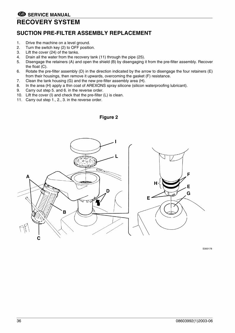
SUCTION PRE-FILTER ASSEMBLY REPLACEMENT
1. Drive the machine on a level ground.2. Turn the switch key (2) to OFF position.3. Lift the cover (24) of the tanks.4. Drain all the water from the recovery tank (11) through the pipe (25).5. Disengage the retainers (A) and open the shield (B) by disengaging it from the pre-filter assembly. Recover
the float (C).6. Rotate the pre-filter assembly (D) in the direction indicated by the arrow to disengage the four retainers (E)
from their housings, then remove it upwards, overcoming the gasket (F) resistance.7. Clean the tank housing (G) and the new pre-filter assembly area (H).8. In the area (H) apply a thin coat of AREXONS spray silicone (silicon waterproofing lubricant).9. Carry out step 5. and 6. in the reverse order.10. Lift the cover (I) and check that the pre-filter (L) is clean.11. Carry out step 1., 2., 3. in the reverse order.
Figure 2
S300178
36 08603992(1)2003-06
SERVICE MANUAL
RECOVERY SYSTEMGB
TANK COVER GASKET AND COMPENSATION HOLE CHECK
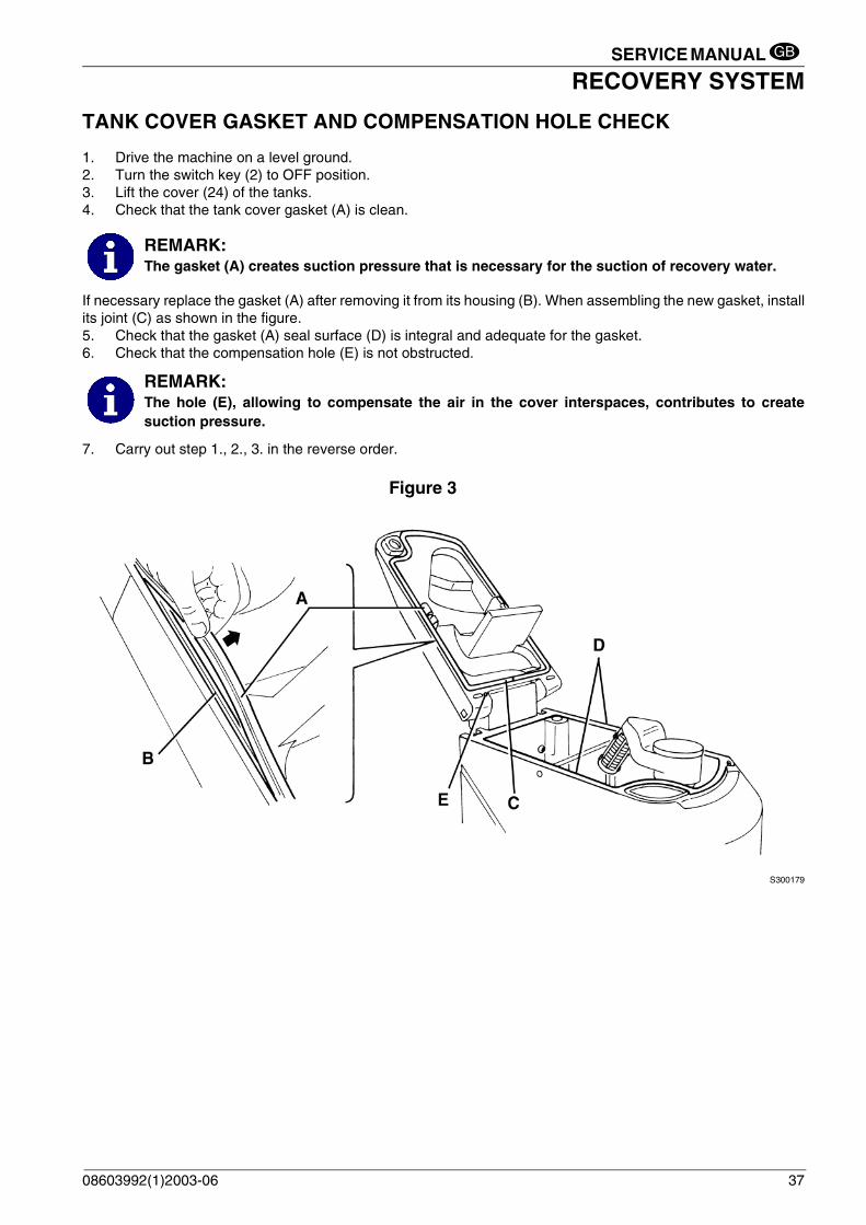
1. Drive the machine on a level ground.2. Turn the switch key (2) to OFF position.3. Lift the cover (24) of the tanks.4. Check that the tank cover gasket (A) is clean.
If necessary replace the gasket (A) after removing it from its housing (B). When assembling the new gasket, installits joint (C) as shown in the figure.5. Check that the gasket (A) seal surface (D) is integral and adequate for the gasket.6. Check that the compensation hole (E) is not obstructed.
7. Carry out step 1., 2., 3. in the reverse order.
Figure 3
S300179
REMARK: The gasket (A) creates suction pressure that is necessary for the suction of recovery water.
REMARK: The hole (E), allowing to compensate the air in the cover interspaces, contributes to createsuction pressure.
08603992(1)2003-06 37

SERVICE MANUAL
RECOVERY SYSTEMGB
SUCTION MOTOR ELECTRICAL INPUT CHECK
1. Drive the machine on a level ground.2. Turn the switch key (2) to OFF position.3. If there is recovery water in the tank (11) remove it through the pipe (25).4. If there is detergent in the tank (14) remove it through the pipe (26).5. Remove the supplied key (28) from its housing and unscrew the tank assembly fastening screw (29).6. To operate on the suction motor (15) carefully lift the tank assembly (27) by means of the maneuver handle
(30).
7. Apply amperometric pliers (A) on a cable of the suction motor (B).8. Activate the suction motor by means of the button (4) and check that the motor input is about 20 A at 24 V.
If the input is greater, carry out the motor brush check (see the procedure on the following pages). Ifnecessary, disassemble the suction motor (see the procedure on the following page), clean it and check itsmoving parts.If the above-mentioned procedures do not lead to a correct motor input it is necessary to replace the motor(see the procedure on the following page).
9. Carry out steps from 1. to 7. in the reverse order.
Figure 4
S300180
WARNING! This procedure must be performed by qualified personnel only.
WARNING! Do not touch uncovered electrical components while performing the following steps.
38 08603992(1)2003-06

SERVICE MANUAL
RECOVERY SYSTEMGB
SUCTION MOTOR REMOVAL
1. Drive the machine on a level ground.2. Turn the switch key (2) to OFF position.3. If there is recovery water in the tank (11) remove it through the pipe (25).4. If there is detergent in the tank (14) remove it through the pipe (26).5. Remove the supplied key (28) from its housing and unscrew the tank assembly fastening screw (29).6. To operate on the suction motor (15) carefully lift the tank assembly (27) by means of the maneuver handle
(30).7. Disconnect the battery (22) negative cable (-).8. Disconnect the suction motor (D) electrical cables (B and C) from the connection (A).9. Remove the motor fastening screws (E).10. Remove the suction motor (D) and the joint (F).11. Recover the gasket (G) that is between the motor and the structure.12. Install in the reverse order of removal.
Figure 5
S300181
REMARK: The motor installed on the machine can either be a FISE or a AMETEK.The following procedure refers to both types of motors.
08603992(1)2003-06 39

SERVICE MANUAL
RECOVERY SYSTEMGB
SUCTION MOTOR BRUSH/CARBON BRUSH CHECK AND REPLACEMENT
1. Drive the machine on a level ground.2. Turn the switch key (2) to OFF position.3. If there is recovery water in the tank (11) remove it through the pipe (25).4. If there is detergent in the tank (14) remove it through the pipe (26).5. Remove the supplied key (28) from its housing and unscrew the tank assembly fastening screw (29).6. To operate on the suction motor (15) carefully lift the tank assembly (27) by means of the maneuver handle
(30).7. Disconnect the battery (22) negative cable (-).8. Remove the cover (A) (that is pressurized) from the suction motor (B).9. Remove the brushes (C).10. Check if the brushes are worn. The brushes are worn when there is not sufficient contact with the motor
armature, because of their use, of the contact surface which is not integral or because the thrust spring isbroken, etc.
11. If necessary, remove the brushes to replace them, by disengaging the lead-in wires (D). It is advisable toreplace all the brushes at the same time.
12. Install in the reverse order of removal.
Figure 6
S300182
REMARK: The motor installed on the machine can either be a FISE or a AMETEK.The following procedure refers to the FISE motor only.
40 08603992(1)2003-06
SERVICE MANUAL
RECOVERY SYSTEMGB
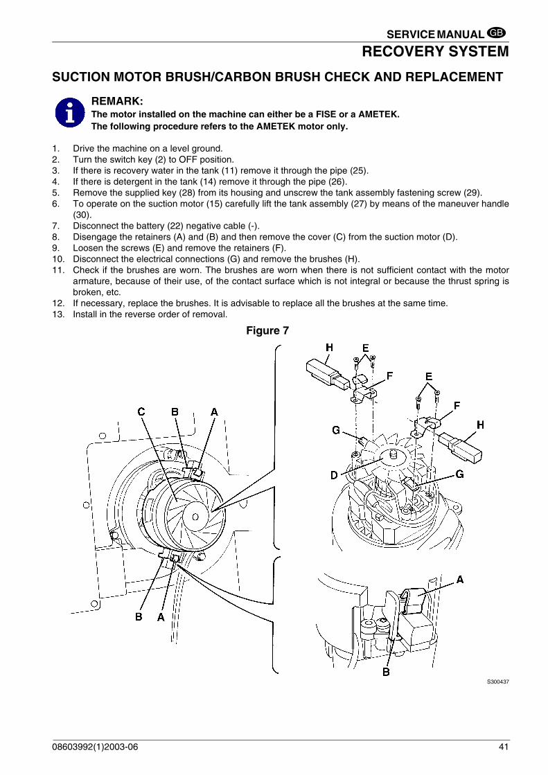
SUCTION MOTOR BRUSH/CARBON BRUSH CHECK AND REPLACEMENT
1. Drive the machine on a level ground.2. Turn the switch key (2) to OFF position.3. If there is recovery water in the tank (11) remove it through the pipe (25).4. If there is detergent in the tank (14) remove it through the pipe (26).5. Remove the supplied key (28) from its housing and unscrew the tank assembly fastening screw (29).6. To operate on the suction motor (15) carefully lift the tank assembly (27) by means of the maneuver handle
(30).7. Disconnect the battery (22) negative cable (-).8. Disengage the retainers (A) and (B) and then remove the cover (C) from the suction motor (D).9. Loosen the screws (E) and remove the retainers (F).10. Disconnect the electrical connections (G) and remove the brushes (H).11. Check if the brushes are worn. The brushes are worn when there is not sufficient contact with the motor
armature, because of their use, of the contact surface which is not integral or because the thrust spring isbroken, etc.
12. If necessary, replace the brushes. It is advisable to replace all the brushes at the same time.13. Install in the reverse order of removal.
Figure 7
S300437
REMARK: The motor installed on the machine can either be a FISE or a AMETEK.The following procedure refers to the AMETEK motor only.
08603992(1)2003-06 41

SERVICE MANUAL
RECOVERY SYSTEMGB
RECOVERY WATER DRAIN PIPE REMOVAL1. Drive the machine on a level ground.2. Turn the switch key (2) to OFF position.3. If there is recovery water in the tank (11) remove it through the pipe (25).4. If there is detergent in the tank (14) remove it through the pipe (26).5. Remove the retaining flange (A) inside the tank (11).6. Remove the supplied key (28) from its housing and unscrew the tank assembly fastening screw (29).7. Carefully lift the tank assembly (27) by means of the maneuver handle (30).8. Pull out the terminal (B) from the tank and remove the recovery water drain pipe (C).9. Before reinstalling the recovery water drain pipe, clean the hole (E). Ensure that the gasket (D) is present,
then warm its end (B) with hot water (to make it become softer) and insert it in the hole (E).10. Carry out step 6. and 7. in the reverse order.11. Install the retaining flange (A) after applying on its surface (F) a thin coat of AREXONS spray silicone (silicone
waterproofing lubricant).12. Carry out steps from 1. to 4. in the reverse order.
Figure 8
S300183
42
Figure 9
S300184
08603992(1)2003-06

SERVICE MANUAL
RECOVERY SYSTEMGB
RECOVERY SYSTEMPULIZIA/CONTROLLO VENTOSA DI ASPIRAZIONE ED EVENTUALE SOSTITUZIONE DEI FLAP
1. Drive the machine on a level ground.2. Turn the switch key (2) to OFF position.3. Lower the suction cap assembly (23) by means of the handle (9).4. Disconnect the suction pipe (A) from the suction cap (C) and from the tank (Q); check that the internal part
of the pipe is free from dirt; otherwise clean it.5. Remove the handwheels (B) and the suction cap assembly (C).6. At the cabinet bench, check that the hole (D) and the spaces (E) are free from dirt; otherwise clean them.7. Check that the edges (I) of the front and rear flaps (F and G) lay down on the same level, along their length;
otherwise adjust their height as described below: – Disengage the retainer (L) and loosen the screws (M) to adjust the rear flap (G); then tighten the screws
and engage the retainer.– Loosen the nuts (N) to adjust the front flap (F); then tighten the nuts.
8. Check that the front and rear flap (F and G) are integral and free from cuts and lacerations; otherwise replacethem as described below. Check that the front corner (H) of the rear flap is not worn; if the rear corner isintegral overturn the flap. If the rear corner is worn, replace the flap as described below:– To replace (or overturn) the rear flap (G) disengage the retainer (L), remove the screws (M) and the
retaining strip (O). Install in the reverse order of removal.– To replace the front flap (F) remove the nuts (N) and the retaining strip (P). Install in the reverse order
of removal.After the flap replacement (or overturning), adjust their height as described by the previous step.
9. Reinstall the suction cap assembly (C) in the correct position and screw down the handwheels (B).10. Connect the suction pipe (A) to the suction cap (C) and to the tank (Q).11. If necessary, adjust the balancing handwheel (R) of the suction cap.
Figure 10
S300438
08603992(1)2003-06 43

SERVICE MANUAL
RECOVERY SYSTEMGB
RECOVERY SYSTEMSUCTION CAP CHECK/CLEANING AND POSSIBLE FLAPS REPLACEMENT (Continues)
Figure 11
S300439SISTEMA DI RACCOLTA DETRITI E POLVERESUCTION CAP REMOVAL1. Drive the machine on a level ground.2. Turn the switch key (2) to OFF position.3. Lower the suction cap assembly (23) by means of the handle (9).4. Disconnect the suction pipe (A) from the suction cap (B).5. Remove the handwheels (C) and the suction cap assembly (B).6. Install in the reverse order of removal and, if necessary, adjust the balancing handwheel (D) of the suction
cap.Figure 12
S300440
44 08603992(1)2003-06
SERVICE MANUAL
RECOVERY SYSTEMGB
RECOVERY SYSTEMTROUBLESHOOTING
OPEN CIRCUITThe thermal fuse (36) determines the open circuit. This system allows to prevent the suction motor and its circuitsfrom being damaged under overload conditions.If there is an open in the electrical circuit, the possible causes are the following.
Suction motor; the thermal fuse (36) activates and opens the electrical circuit.
Possible cause:1. The motor is damaged (check the motor brushes/electrical input).Wait at least 2 minutes after the break and, when the problem is solved, push the thermal fuse button (36).
DIRTY WATER SUCTION IS INSUFFICIENT OR THERE IS NO SUCTION
Possible cause:1. The automatic float shut-off (12) is activated because the water recovery tank (11) is too full (empty the water
recovery tank).2. The float shield (12) or the suction filter are dirty (clean them).3. The tank cover (24) is not correctly positioned (place it correctly).4. The tank cover gasket is not efficient or the compensating hole is obstructed (remove the causes).5. The suction cap or suction pipe obstructed or damaged (clean/repair/replace them)6. The battery voltage is too low (charge the battery).7. The electrical motor brushes are worn (replace the electrical motor brushes).8. Malfunction in the electrical suction motor (repair or replace the electrical motor).9. The thermal fuse (36) is deactivated (remove the cause of deactivation).10. The suction ON/OFF switch (4) is broken (replace it).11. The wiring harness is damaged (repair it).12. The suction motor electromagnetic switch is broken (replace it).13. The relay electronic board is damaged (replace it)
THE SUCTION CAP LEAVES LINING OR DOES NOT COLLECT WATER
Possible cause:1. There is debris under the suction cap lip (remove it).2. The suction cap flap lips are torn or worn (replace the flaps).3. The suction cap is unbalanced [balance it by means of the handwheel (38)].
08603992(1)2003-06 45

SERVICE MANUAL
TRACTION SYSTEMGB
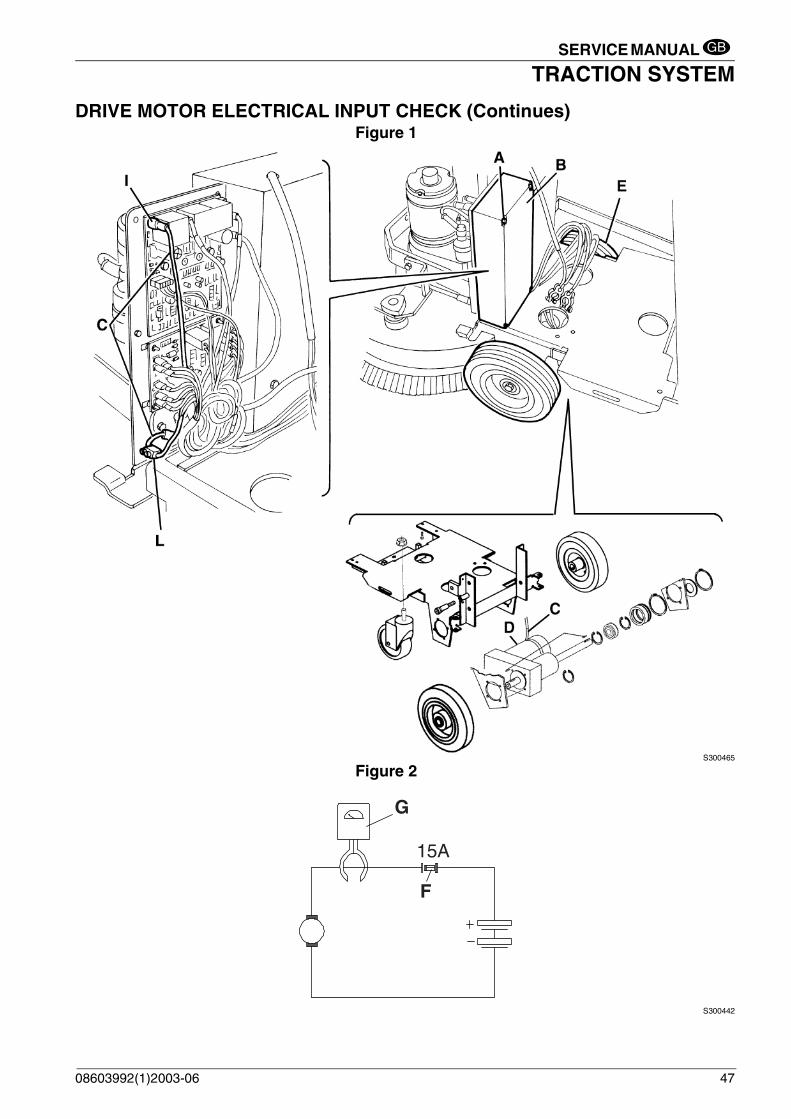
TRACTION SYSTEMDRIVE MOTOR ELECTRICAL INPUT CHECK
1. Drive the machine on a level ground.2. Turn the switch key (2) to OFF position.3. If there is recovery water in the tank (11) remove it through the pipe (25).4. If there is detergent in the tank (14) remove it through the pipe (26).5. Remove the supplied key (28) from its housing and unscrew the tank assembly fastening screw (29).6. Carefully lift the tank assembly (27) by means of the maneuver handle (30).7. Disconnect the battery (22) negative cable (-).8. Disconnect the other cables of the batteries.9. Remove the batteries (22).10. Remove the battery frame (31).11. Unscrew the screws (A) and the electronic case cover (B).
Disconnect the traction motor (D) cables (C) from the connection (I) (electrical symbol T4) to the electronicboard and from the connection (L).
12. Lift the driving wheels (E) a few centimeters from the ground by inserting adequate shims under the brush(18) or under the front wheel (32). Then securely fix the machine in this position so that the driving wheels(E) can turn freely without touching the ground during the following tests.
13. Connect the traction motor to the machine battery, as described in the underlying diagram, inserting the 15A fuse (F), for safety’s sake.
14. With an ammeter (G) check that the drive motor input is 3-4 A at 24V.If the input is greater, carry out the motor brush check (see the procedure on the following pages). Ifnecessary, disassemble the traction motor (see the procedure on the following page), clean it and check itsmoving parts.If the above-mentioned procedures do not lead to a correct motor input it is necessary to replace the motor(see the procedure on the following page).
15. Carry out steps from 1. to 12. in the reverse order.
WARNING! This procedure must be performed by qualified personnel only.
WARNING! Pay attention to the driving wheel (E) rotation while performing the following steps.
46 08603992(1)2003-06
SERVICE MANUAL
TRACTION SYSTEMGB
DRIVE MOTOR ELECTRICAL INPUT CHECK (Continues)Figure 1
S300465
Figure 2
S300442
G
F
15A
08603992(1)2003-06 47

SERVICE MANUAL
TRACTION SYSTEMGB
DRIVE MOTOR REMOVAL
1. Remove the brush (18).2. Drive the machine on a level ground.3. Remove the suction cap (see the related paragraph).4. Turn the switch key (2) to OFF position.5. If there is recovery water in the tank (11) remove it through the pipe (25).6. If there is detergent in the tank (14) remove it through the pipe (26).7. Remove the supplied key (28) from its housing and unscrew the tank assembly fastening screw (29).8. Carefully lift the tank assembly (27) by means of the maneuver handle (30).9. Disconnect the battery (22) negative cable (-).10. Disconnect the other cables of the batteries.11. Remove the batteries (22).12. Remove the battery frame (31).13. Unscrew the screws (A) and the electronic case cover (B).
Disconnect the traction motor (D) cables (C) from the connection (M) (electrical symbol T4) to the electronicboard and from the connection (N).
14. Carefully lower the tank assembly (27) by means of the maneuver handle (30).15. Remove the left wheel (F) and the snap ring (G).16. Lay down the machine on one side and set it down carefully on proper guards (H).17. Remove the right wheel (I).18. Remove the four screws (L).19. Remove the motor assembly with the reduction unit (D).20. Install in the reverse order of removal.
Figure 3
S300466
48 08603992(1)2003-06

SERVICE MANUAL
TRACTION SYSTEMGB
DRIVE MOTOR REMOVAL (Continues)
Figure 4
S300191
Figure 5
S300192
08603992(1)2003-06 49

SERVICE MANUAL
TRACTION SYSTEMGB
DRIVE MOTOR BRUSH (OR CARBON BRUSH) CHECK AND REPLACEMENT
1. Remove the brush (18).2. Drive the machine on a level ground.3. Remove the suction cap (see the related paragraph).4. Turn the switch key (2) to OFF position.5. If there is recovery water in the tank (11) remove it through the pipe (25).6. If there is detergent in the tank (14) remove it through the pipe (26).7. Remove the supplied key (28) from its housing and unscrew the tank assembly fastening screw (29).8. Carefully lift the tank assembly (27) by means of the maneuver handle (30).9. Disconnect the battery (22) negative cable (-).10. Disconnect the other cables of the batteries.11. Remove the batteries (22).12. Remove the battery frame (31).13. Carefully lower the tank assembly (27) by means of the maneuver handle (30).14. Lay down the machine on one side and set it down carefully on proper guards (A).15. Carefully open the tank assembly (I) completely by means of the maneuver handle (30).16. Remove the two screws (B) and lightly slide the tap-solenoid valve assembly (C).17. Clean the exterior part of the traction motor (L) from dirty and dust, then mark the reciprocal position (D)
between the cover (E) and the motor body.18. Remove the screws (F) and the cover (E).19. Check if the two brushes (G) are worn. The brushes are worn when there is not sufficient contact with the
motor armature, because of their use, of the contact surface which is not integral or because the thrust springis broken, etc.
20. If necessary, remove the brushes to replace them, by disengaging the lead-in wires (H).It is advisable to replace all the brushes at the same time.
21. Install in the reverse order of removal.
Figure 6
S300193
50 08603992(1)2003-06

SERVICE MANUAL
TRACTION SYSTEMGB
TRACTION SYSTEMDRIVE MOTOR BRUSH (OR CARBON BRUSH) CHECK AND REPLACEMENT (Continue)
Figure 7
S300467
08603992(1)2003-06 51
SERVICE MANUAL
TRACTION SYSTEMGB
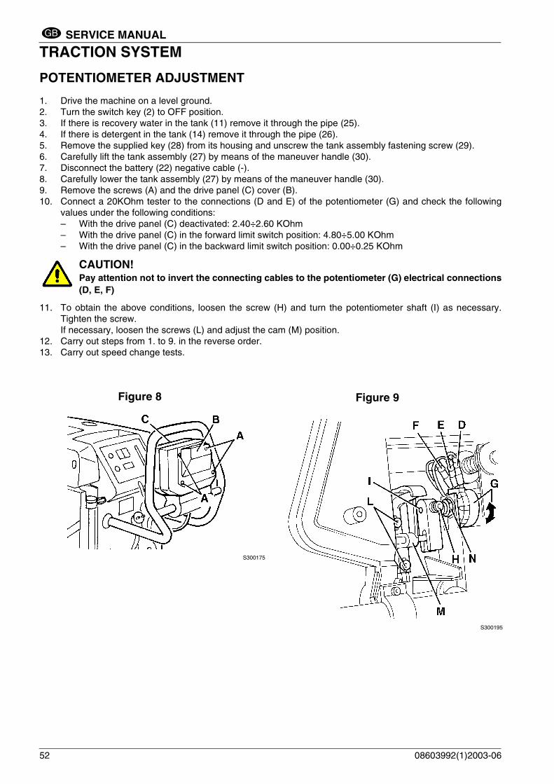
POTENTIOMETER ADJUSTMENT
1. Drive the machine on a level ground.2. Turn the switch key (2) to OFF position.3. If there is recovery water in the tank (11) remove it through the pipe (25).4. If there is detergent in the tank (14) remove it through the pipe (26).5. Remove the supplied key (28) from its housing and unscrew the tank assembly fastening screw (29).6. Carefully lift the tank assembly (27) by means of the maneuver handle (30).7. Disconnect the battery (22) negative cable (-).8. Carefully lower the tank assembly (27) by means of the maneuver handle (30).9. Remove the screws (A) and the drive panel (C) cover (B).10. Connect a 20KOhm tester to the connections (D and E) of the potentiometer (G) and check the following
values under the following conditions:– With the drive panel (C) deactivated: 2.40÷2.60 KOhm– With the drive panel (C) in the forward limit switch position: 4.80÷5.00 KOhm– With the drive panel (C) in the backward limit switch position: 0.00÷0.25 KOhm
11. To obtain the above conditions, loosen the screw (H) and turn the potentiometer shaft (I) as necessary.Tighten the screw.If necessary, loosen the screws (L) and adjust the cam (M) position.
12. Carry out steps from 1. to 9. in the reverse order.13. Carry out speed change tests.
CAUTION!Pay attention not to invert the connecting cables to the potentiometer (G) electrical connections(D, E, F)
Figure 8
S300175
52
Figure 9
S300195
08603992(1)2003-06
SERVICE MANUAL
TRACTION SYSTEMGB
TROUBLESHOOTING
OPEN CIRCUIT
The thermal fuse (34) determines the open circuit. This system allows to prevent the drive motor circuits from beingdamaged under overload conditions.If there is an open in the electrical circuit, the possible causes are the following.
Drive motor; the thermal fuse (34) activates and opens the electrical circuit.
Possible cause:1. There are bulky debris or cords under the machine or around the driving wheels (remove the debris).2. The motor is damaged (check the motor brushes/motor electrical input).3. The slope is excessive (do not use traction to drive the machine on slopes)Wait at least 2 minutes after the break and, when the problem is solved, push the thermal fuse button (34).
THE MACHINE DOES NOT MOVE
Other possible cause:1. The switch (39) is to OFF position.2. The battery voltage is too low (charge the battery).3. The potentiometer inside the drive panel (8) is misadjusted or broken (adjust or replace it).4. The potentiometer (1) is broken (replace it).5. The traction electronic board has a malfunction (replace it).6. The thermal fuse (34) is deactivated (remove the cause of deactivation).7. The wiring harness is damaged (repair it).
08603992(1)2003-06 53

SERVICE MANUAL
ELECTRICAL SYSTEMGB
ELECTRICAL SYSTEMBATTERY REMOVAL
1. Drive the machine on a level ground.2. Turn the switch key (2) to OFF position.3. If there is recovery water in the tank (11) remove it through the pipe (25).4. If there is detergent in the tank (14) remove it through the pipe (26).5. Remove the supplied key (28) from its housing and unscrew the tank assembly fastening screw (29).6. Carefully lift the tank assembly (27) by means of the maneuver handle (30). 7. Disconnect the battery (22) negative cable (-).8. Disconnect the other cables of the batteries.9. Remove the batteries (22).10. If necessary, remove the battery frame (31).11. Install in the reverse order of removal.
BATTERY MAINTENANCE AND RECHARGING
See Use and Maintenance Manual
TRACTION ELECTRONIC BOARD REPLACEMENT
1. Remove the batteries (See the previous procedure).2. Unscrew the screws (A) and the electronic case cover (B).3. Disconnect all the electrical connections of the board (C) (See the wiring diagram).4. Remove the screws (D) and the traction electronic board (C).5. Install in the reverse order of removal.
Figure 1
S300468
REMARK: It is not necessary to perform the electronic programming of the new boards.
54 08603992(1)2003-06

SERVICE MANUAL
ELECTRICAL SYSTEMGB
ELECTRICAL SYSTEMSERVICE ELECTRONIC BOARD REPLACEMENT
1. Remove the batteries (See the previous procedure).2. Unscrew the screws (A) and the electronic case cover (B).3. Disconnect all the electrical connections of the board (C) (See the wiring diagram).4. Disengage the retainers (D) and remove the service electronic board (C).5. Install in the reverse order of removal.
Figure 2
S300469
REMARK: It is not necessary to perform the electronic programming of the new board.
08603992(1)2003-06 55

SERVICE MANUAL
ELECTRICAL SYSTEMGB
ELECTRONIC BOARD CONTROLLING THE BRUSH MOTOR OPERATION CHECK AND REPLACEMENT (BA 6124D Only))
Electronic board operation check.
1. Wait until the brush motor (16) and the electronic board (42) are cool after machine operation.2. Drive the machine on a level ground.3. Turn the switch key (2) to OFF position.4. Turn the drive switch (39) to "0" position (OFF).5. If there is recovery water in the tank (11) remove it through the pipe (25).6. If there is detergent in the tank (14) remove it through the pipe (26).7. Remove the supplied key (28) from its housing and unscrew the tank assembly fastening screw (29).8. To operate on the brush motor (16) carefully lift the tank assembly (27) by means of the maneuver handle
(30).9. Unscrew the nuts (A) and remove the brush motor cover (B).
10. Turn the switch key (2) to the ON position; activate the brushes by means of switch (3) and while holding thedrive panel (8), check if the green LED (C) is lit, then proceed as follows:– if the LED (C) is not lit, the electronic board is not faulty and the trouble is located earlier in the process.– if the LED (C) is lit, and the electric brush motor (D) does not rotate, the electronic board is faulty, and it
must be replaced; for its replacement follow the procedure below. – if the LED (C) is lit and the electric brush motor (D) rotates, but the brushes do not rotate, the trouble is
located in the brush belt transmission system.
Electronic board replacement
11. Disconnect the battery (22) negative cable (-).12. Disconnect all the electrical cables from the connections (G) of the electronic board (E) (See the wiring
diagram).13. Install in the reverse order of removal.
Reassembly
14. Install in the reverse order of removal.
REMARK: It is not necessary to perform the electronic programming of the new board.
WARNING !This procedure must be performed by qualified personnel only.
WARNING !Pay attention to brush rotation during execution of the next step.
56 08603992(1)2003-06

SERVICE MANUAL
ELECTRICAL SYSTEMGB
ELECTRONIC BOARD CONTROLLING THE BRUSH MOTOR OPERATION CHECK AND REPLACEMENT (BA 6124D Only) (continues)
Figure 3
S300470
08603992(1)2003-06 57
SERVICE MANUAL
ELECTRICAL SYSTEMGB
TROUBLESHOOTING
See the previous chapters related to the use of the electrical system.Other possible malfunction causes are:1. The battery is discharged or its connections are not efficient (charge the battery or clean the connections).2. Broken battery (check battery's open-circuit voltage)
3. The thermal fuses are deactivated (activate them).4. The wiring harness is cut or shorted to ground (repair it)5. The safety micro-switch (41) is not efficient (replace it).6. The safety micro-switch (49) is not efficient (replace it) (only for version with Battery Charger equipped with
the machine)
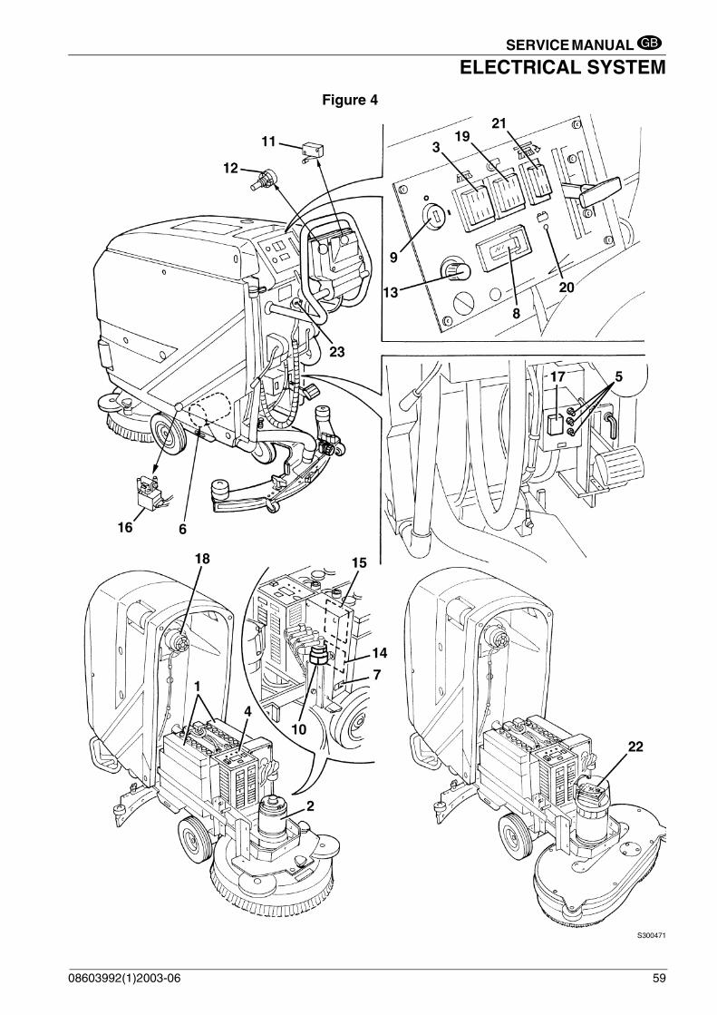
COMPONENT LAYOUT
1. Batteries2. Brush motor3. Brush motor switch4. Battery Charger 5. Reset thermal fuse6. Drive motor (*)7. Battery type switch (WET or GEL)8. Hour counter9. Ignition key switch10. Electromagnetic switch11. Brush rotation consent micro-switch12. Traction speed control potentiometer (5KOhm)13. Traction speed control potentiometer (47KOhm)14. Service electronic board15. Traction control electronic board16. Detergent supply solenoid valve17. Traction switch18. Suction motor19. Suction motor switch20. Battery condition indicator21. Brush release push-button (BA 6124 D only)22. Brush motor electronic board (BA 6124 D only)23. Electrical connection to the network, during battery recharging
(*) For BA 5321D and BA 6124D
REMARK: For the versions equipped with Battery Charger, a fault in the Battery Charger or its connectionscan cause a malfunction of the machine.
58 08603992(1)2003-06
SERVICE MANUAL
ELECTRICAL SYSTEMGB
Figure 4
S300471
08603992(1)2003-06 59

SERVICE MANUAL
ELECTRICAL SYSTEMGB
BA 5321 WIRING DIAGRAM
S300472
60 08603992(1)2003-06

SERVICE MANUAL
ELECTRICAL SYSTEMGB
WIRING DIAGRAM BA 5321D
S300473
08603992(1)2003-06 61
SERVICE MANUAL
ELECTRICAL SYSTEMGB
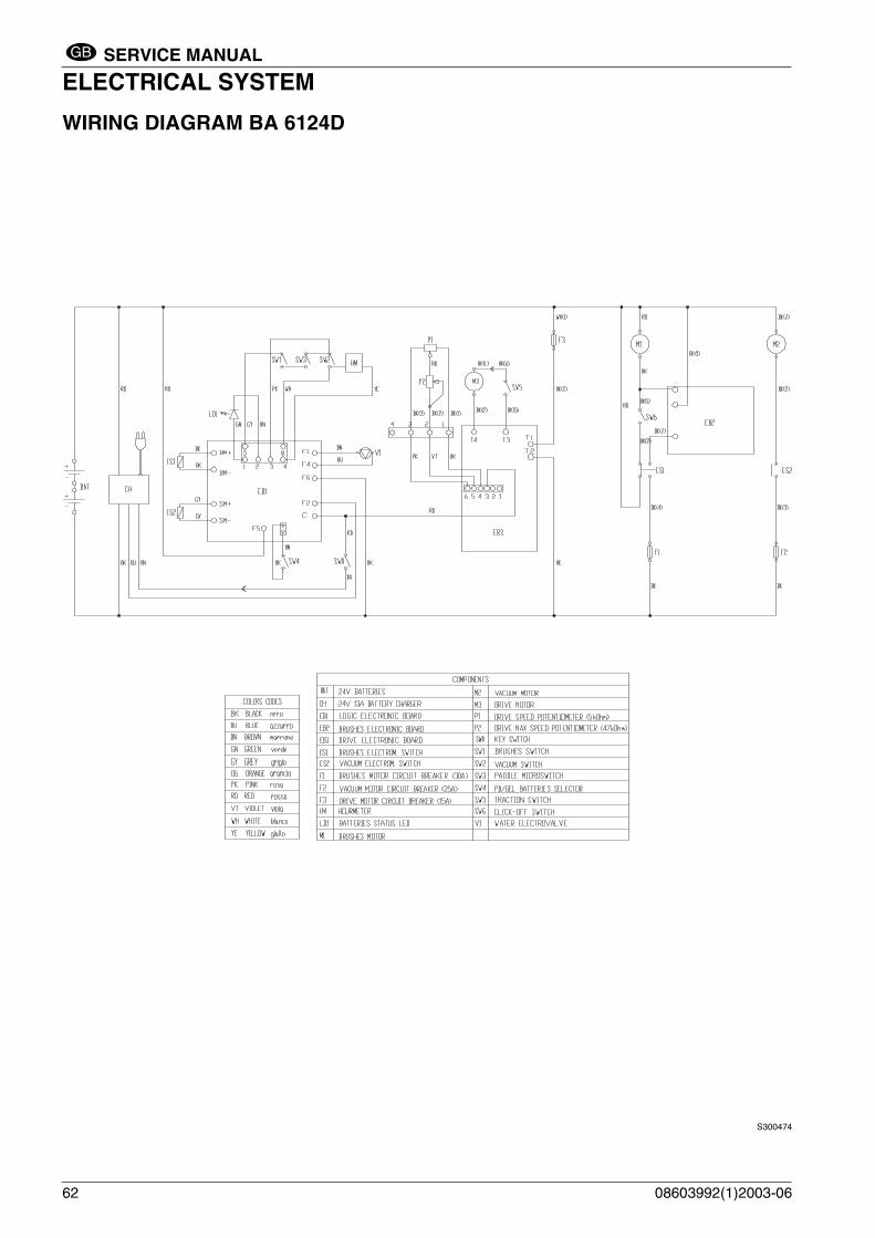
WIRING DIAGRAM BA 6124D
S300474
62 08603992(1)2003-06