ba astra - h .book - opel lebanon - opel new cars, vans
TRANSCRIPT
OPEL Astra
Operation, Safety, Maintenance
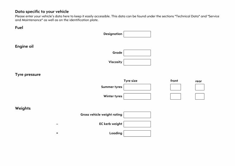
Data specific to your vehiclePlease enter your vehicle’s data here to keep it easily accessible. This data can be found under the sections "Technical Data" and "Service and Maintenance" as well as on the identification plate.
Fuel Designation
Engine oil Grade
Viscosity
Tyre pressure Tyre size front rear
Summer tyres
Winter tyres
Weights Gross vehicle weight rating
– EC kerb weight
= Loading
IntroductionYour vehicle is an intelligent synthesis of advanced technology, proven safety, environmental friendliness and economy.
It now lies with you to drive your vehicle safely and ensure that it performs perfectly. This Owner’s Manual provides you with all the necessary information to that end.
Make sure your passengers are aware of the possible risk of accident and injury which may result from improper use of the vehicle.
You must always comply with the specific laws of the country in which you are driving. These laws may differ from the information in this Owner’s Manual.
When this Manual refers to a workshop visit, we recommend your Opel Service Partner.
All Opel Service Partners provide first-class service at reasonable prices. Experienced mechanics trained by Opel work according to specific Opel instructions.
The customer literature pack, consisting of Owner’s Manual, infotainment system instructions, Service Booklet and Warranty Booklet should always be kept in the vehicle: ready to hand in the glove compartment.
Make use of the Owner’s Manual z The "In Brief" section will give you an
initial overview.
z The table of contents at the beginning of the owner’s manual and within the individual chapters will show you where everything is.
z Its index will help you find what you want.
z Yellow arrows in the illustrations serve as points of reference or indicate some action to be performed.
z Black arrows in the illustrations indicate a reaction or a second action to be performed.
z This Owner’s Manual refers to left-hand drive vehicles. Operation in right-hand drive vehicles is similar.
z The Owner’s Manual makes reference to internal engine designations. The associated sales designations are found in the section "Technical Data".
z Directional data, e.g. left or right, or front or back, in the descriptions always relate to the direction of travel.
Symbols6 Continue reading on next page.
Equipment marked with 3 is not found in all vehicles (model variants, engine range, national variants, special equipment, genuine Opel parts and accessories).
Page references are indicated with 3, which means "see page".
9 Danger, 9 Warning, Caution
We wish you many hours of pleasurable driving.
Adam Opel GmbH
9 Danger
Text marked 9 Danger provides information on possible fatal injury. Disregard of the instructions may endanger life.
9 Warning
Text marked 9 Warning provides information on risk of accident or injury. Disregard of the instructions may lead to injury.
Caution
Text marked Caution provides information on possible damage to the vehicle. Disregard of the instructions may lead to vehicle damage.

Contents In brief ....................................................... 2Keys, doors, windows, TwinTop ........... 28Seats, interior .......................................... 64Instruments, controls ............................ 108Lighting ................................................. 138Infotainment system ............................ 147Climate control .................................... 150Driving and operation ......................... 170Self-help, vehicle care .......................... 226Opel Service, maintenance ................. 274Technical data .................................... 292Customer information ......................... 335Index ...................................................... 336
2 In brief
In brief
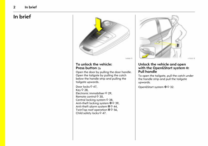
Picture no: 16968t.tifTo unlock the vehicle: Press button q Open the door by pulling the door handle. Open the tailgate by pulling the catch below the handle strip and pulling the tailgate upwards.
Door locks 3 47, Key 3 28, Electronic immobiliser 3 29, Remote control 3 30, Central locking system 3 38, Anti-theft locking system 3 3 39, Anti-theft alarm system 3 3 44, TwinTop roof operation 3 3 56, Child safety locks 3 47.
Picture no: 17333t.tifUnlock the vehicle and open with the Open&Start system 3: Pull handle To open the tailgate, pull the catch under the handle strip and pull the tailgate upwards.
Open&Start system 3 3 32.
3In brief
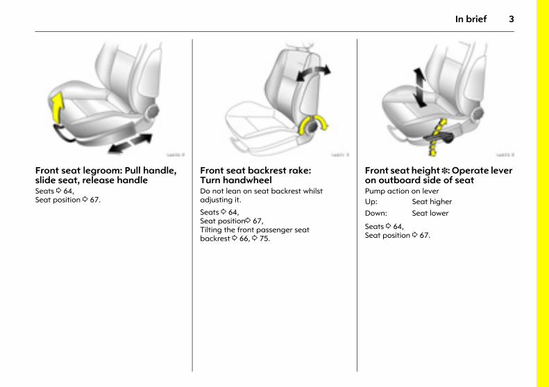
Picture no: 16970t.tifFront seat legroom: Pull handle, slide seat, release handle Seats 3 64, Seat position 3 67.
Picture no: 16971t.tifFront seat backrest rake: Turn handwheel Do not lean on seat backrest whilst adjusting it.
Seats 3 64, Seat position3 67, Tilting the front passenger seat backrest 3 66, 3 75.
Picture no: 16973t.tifFront seat height 3: Operate lever on outboard side of seat Pump action on lever
Seats 3 64, Seat position 3 67.
Up: Seat higher
Down: Seat lower
4 In brief
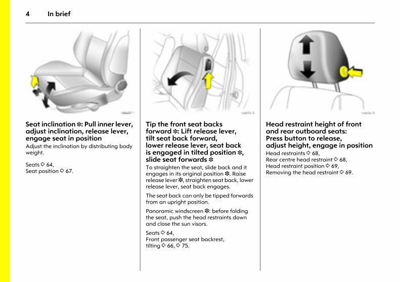
Picture no: 18607t.tifSeat inclination 3: Pull inner lever, adjust inclination, release lever, engage seat in position Adjust the inclination by distributing body weight.
Seats 3 64, Seat position 3 67.
Picture no: 16975t.tifTip the front seat backs forward 3: Lift release lever, tilt seat back forward, lower release lever, seat back is engaged in tilted position 3, slide seat forwards 3 To straighten the seat, slide back and it engages in its original position 3. Raise release lever 3, straighten seat back, lower release lever, seat back engages.
The seat back can only be tipped forwards from an upright position.
Panoramic windscreen 3: before folding the seat, push the head restraints down and close the sun visors.
Seats 3 64, Front passenger seat backrest, tilting 3 66, 3 75.
Picture no: 16976t.tifHead restraint height of front and rear outboard seats: Press button to release, adjust height, engage in position Head restraints 3 68, Rear centre head restraint 3 68, Head restraint position 3 69, Removing the head restraint 3 69.
5In brief
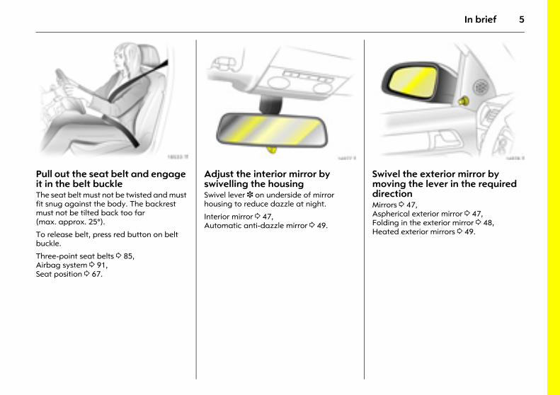
Picture no: 18533t.tifPull out the seat belt and engage it in the belt buckle The seat belt must not be twisted and must fit snug against the body. The backrest must not be tilted back too far (max. approx. 25°).
To release belt, press red button on belt buckle.
Three-point seat belts 3 85, Airbag system 3 91, Seat position 3 67.
Picture no: 16977t.tifAdjust the interior mirror by swivelling the housingSwivel lever 3 on underside of mirror housing to reduce dazzle at night.
Interior mirror 3 47, Automatic anti-dazzle mirror 3 49.
Picture no: 16978t.tifSwivel the exterior mirror by moving the lever in the required direction Mirrors 3 47, Aspherical exterior mirror 3 47, Folding in the exterior mirror 3 48, Heated exterior mirrors 3 49.
6 In brief
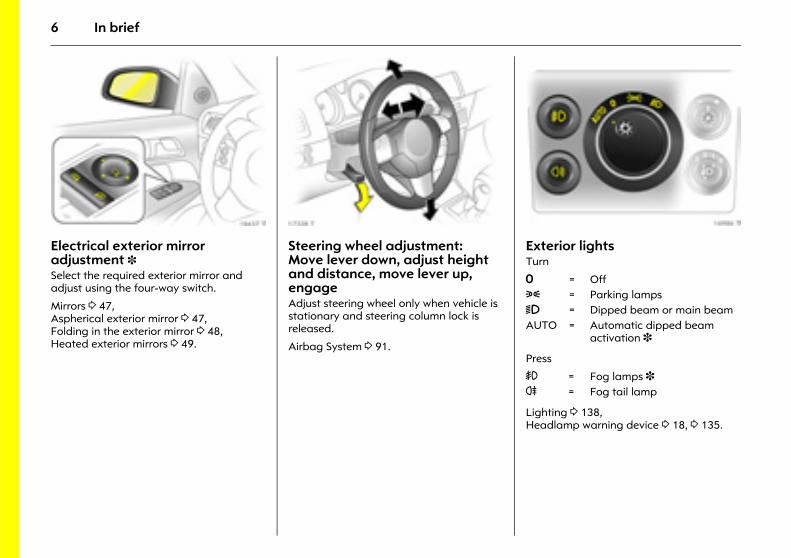
Picture no: 18437T.tifElectrical exterior mirror adjustment 3 Select the required exterior mirror and adjust using the four-way switch.
Mirrors 3 47, Aspherical exterior mirror 3 47, Folding in the exterior mirror 3 48, Heated exterior mirrors 3 49.
Picture no: 17328t.tifSteering wheel adjustment: Move lever down, adjust height and distance, move lever up, engage Adjust steering wheel only when vehicle is stationary and steering column lock is released.
Airbag System 3 91.
Picture no: 16986t.tifExterior lights Turn
Press
Lighting 3 138, Headlamp warning device 3 18, 3 135.
7 = Off8 = Parking lamps9 = Dipped beam or main beam AUTO = Automatic dipped beam
activation 3
> = Fog lamps 3 r = Fog tail lamp
7In brief
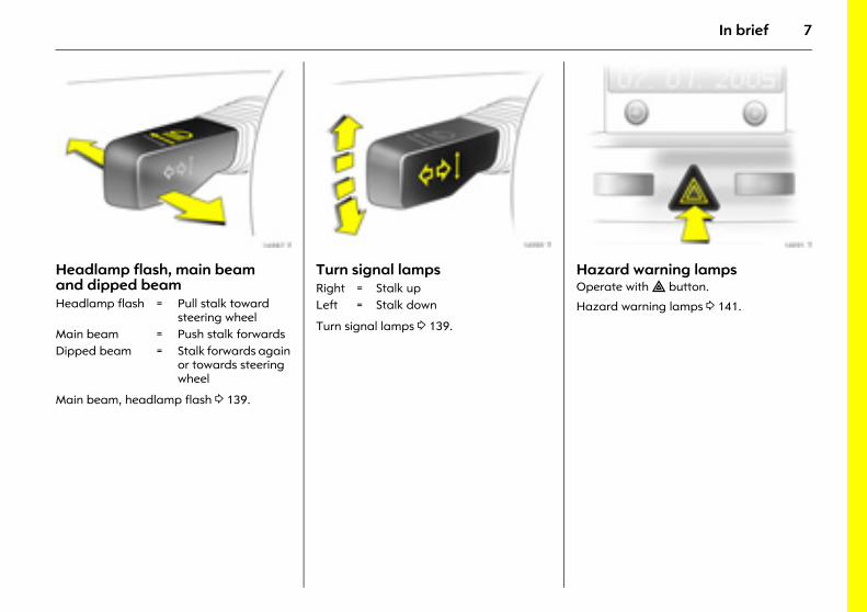
Picture no: 16987t.tifHeadlamp flash, main beam and dipped beam
Main beam, headlamp flash 3 139.
Picture no: 16989t.tifTurn signal lamps
Turn signal lamps 3 139.
Picture no: 16991t.tifHazard warning lamps Operate with ¨ button.
Hazard warning lamps 3 141. Headlamp flash = Pull stalk toward steering wheel
Main beam = Push stalk forwardsDipped beam = Stalk forwards again
or towards steering wheel
Right = Stalk upLeft = Stalk down
8 In brief
9In brief
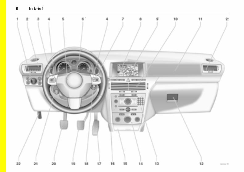
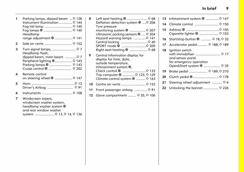
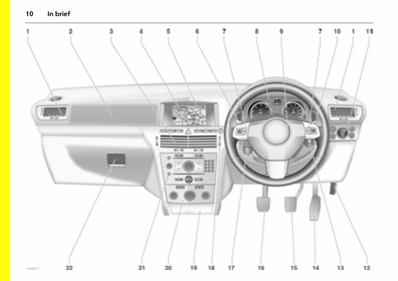
1 Parking lamps, dipped beam ... 3 138Instrument illumination .............. 3 144Fog tail lamp .............................. 3 140Fog lamps 3 ............................... 3 140Headlamp range adjustment 3 ................... 3 141
2 Side air vents .............................. 3 152
3 Turn signal lamps, .......................... 3 7Headlamp flash,dipped beam, main beam .............3 7Peripheral lighting 3................... 3 143Parking lamps 3 ........................ 3 143Cruise control 3 ......................... 3 202
4 Remote control on steering wheel 3 ................... 3 147
5 Horn ...............................................3 13Driver’s Airbag ............................ 3 91
6 Instruments ................................. 3 108
7 Windscreen wipers,windscreen washer system,headlamp washer system 3 and rear window washersystem ......................3 13, 3 14, 3 136
8 Left seat heating 3 ...................... 3 68Deflation detection system 3 ....3 206Tyre pressure monitoring system 3 ..................3 207Ultrasonic parking sensors 3 .... 3 204Hazard warning lamps ..............3 141Central locking ..............................3 40SPORT mode 3 ...........................3 200Right seat heating 3 ................... 3 68
9 Central information display fordisplay for time, date,outside temperature,infotainment system 3,Check control 3 ..........................3 133Trip computer 3 ..............3 123, 3 129Climate control system 3 .......... 3 163
10 Centre air vents .......................... 3 152
11 Front passenger airbag .............. 3 91
12 Glove compartment ......... 3 35, 3 106
13 Infotainment system 3 .............. 3 147
14 Climate control .......................... 3 150
15 Ashtray 3 ....................................3 105Cigarette lighter 3 ..................... 3 103
16 Start/stop button 3 ........... 3 18, 3 32
17 Accelerator pedal........... 3 188, 3 189
18 Ignition switch with immobiliser ........................... 3 17and sensor panel for emergency operation Open&Start system 3 .................. 3 35
19 Brake pedal .................... 3 189, 3 210
20 Clutch pedal 3 ............................ 3 178
21 Steering wheel adjustment ........... 3 6
22 Unlocking the bonnet................. 3 226
10 In brief
11In brief
1 Side air vents .............................. 3 152
2 Front passenger airbag .............. 3 91
3 Centre air vents ......................... 3 152
4 Central information display fortime, date,outside temperature,infotainment system 3,Check control 3 .......................... 3 133Trip computer 3 ..............3 123, 3 129Climate control system 3 ......... 3 163
5 Left seat heating 3 ..................... 3 68Deflation detection system 3 ... 3 206Tyre pressure monitoring system 3 .................. 3 207Ultrasonic parking sensors 3 ... 3 204Hazard warning lamps .............. 3 141Central locking ..............................3 40SPORT mode 3 ........................... 3 200Right seat heating 3 ................... 3 68
6 Turn signal lamps, ..........................3 7Headlamp flash,dipped beam, main beam .............3 7Peripheral lighting 3................... 3 143Parking lamps 3 ........................ 3 143Cruise control 3 ......................... 3 202
7 Remote control on steering wheel 3 ....................3 147
8 Instruments ..................................3 108
9 Horn ...............................................3 13Driver’s Airbag ............................. 3 91
10 Windscreen wipers,windscreen washer system, headlamp washer system 3 and rear window washer system ......... 3 13, 3 14, 3 136
11 Parking lamps, dipped beam ....3 138Instrument illumination ..............3 144Fog tail lamp ...............................3 140Fog lamps 3 ................................3 140Headlamp range adjustment 3 ...................3 141
12 Unlocking the bonnet ................. 3 226
13 Ignition switch with immobiliser ........................... 3 17
and sensor panel for emergency operationOpen&Start system 3 .................. 3 35
14 Accelerator pedal........... 3 188, 3 189
15 Brake pedal .................... 3 189, 3 210
16 Clutch pedal 3 ............................ 3 178
17 Steering wheel adjustment ........... 3 6
18 Start/stop button 3 ........... 3 18, 3 32
19 Ashtray 3 ....................................3 105 Cigarette lighter 3 ..................... 3 103
20 Climate control .......................... 3 150
21 Infotainment system 3 .............. 3 147
22 Glove compartment ........ 3 35, 3 106
12 In brief
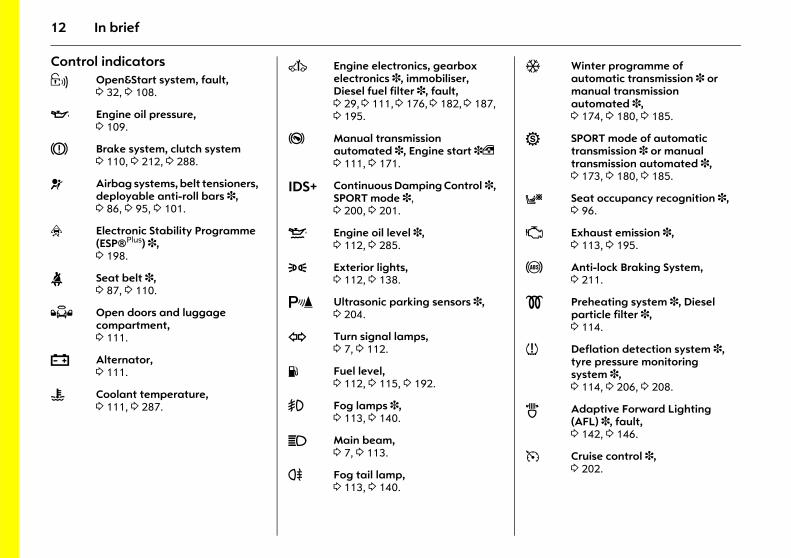
Control indicators 0 Open&Start system, fault,
3 32, 3 108.
I Engine oil pressure, 3 109.
R Brake system, clutch system 3 110, 3 212, 3 288.
v Airbag systems, belt tensioners, deployable anti-roll bars 3, 3 86, 3 95, 3 101.
v Electronic Stability Programme (ESP®Plus) 3,3 198.
X Seat belt 3,3 87, 3 110.
Q Open doors and luggage compartment, 3 111.
p Alternator, 3 111.
W Coolant temperature, 3 111, 3 287.
A Engine electronics, gearbox electronics 3, immobiliser, Diesel fuel filter 3, fault, 3 29, 3 111, 3 176, 3 182, 3 187, 3 195.
j Manual transmission automated 3, Engine start 3, 3 111, 3 171.
IDS+ Continuous Damping Control 3, SPORT mode 3, 3 200, 3 201.
S Engine oil level 3, 3 112, 3 285.
8 Exterior lights, 3 112, 3 138.
r Ultrasonic parking sensors 3, 3 204.
O Turn signal lamps, 3 7, 3 112.
Y Fuel level, 3 112, 3 115, 3 192.
> Fog lamps 3, 3 113, 3 140.
C Main beam, 3 7, 3 113.
r Fog tail lamp, 3 113, 3 140.
T Winter programme of automatic transmission 3 or manual transmission automated 3, 3 174, 3 180, 3 185.
1 SPORT mode of automatic transmission 3 or manual transmission automated 3, 3 173, 3 180, 3 185.
y Seat occupancy recognition 3, 3 96.
Z Exhaust emission 3, 3 113, 3 195.
u Anti-lock Braking System, 3 211.
! Preheating system 3, Diesel particle filter 3,3 114.
w Deflation detection system 3, tyre pressure monitoring system 3, 3 114, 3 206, 3 208.
B Adaptive Forward Lighting (AFL) 3, fault, 3 142, 3 146.
m Cruise control 3, 3 202.
13In brief
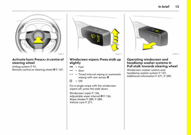
Picture no: 16992t.tifActivate horn: Press j in centre of steering wheel Airbag system 3 91, Remote control on steering wheel 3 3 147.
Picture no: 16993t.tifWindscreen wipers: Press stalk up slightly
For a single swipe with the windscreen wipers off, press the stalk down.
Windscreen wiper 3 136, Adjustable wiper interval 3 3 136, Wiper blades 3 289, 3 289, Vehicle care 3 271.
Picture no: 16996t.tifOperating windscreen and headlamp washer systems 3: Pull stalk towards steering wheel Windscreen washer system and headlamp washer system 3 137, Additional information 3 271, 3 290.
& = Fast% = Slow $ = Timed interval wiping or automatic
wiping with rain sensor 3§ = Off
14 In brief
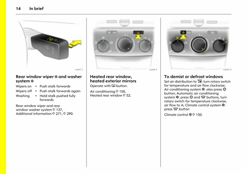
Picture no: 16997t.tifRear window wiper 3 and washer system 3
Rear window wiper and rear window washer system 3 137, Additional information 3 271, 3 290.
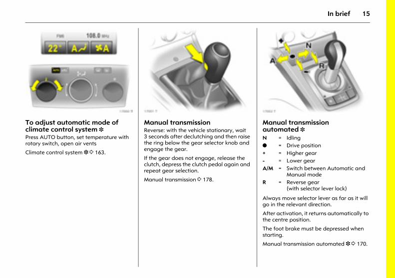
Picture no: 16998t.tifHeated rear window, heated exterior mirrors Operate with Ü button.
Air conditioning 3 150, Heated rear window 3 52.
Picture no: 16999t.tifTo demist or defrost windows Set air distribution to l, turn rotary switch for temperature and air flow clockwise; Air conditioning system 3: also press n button; Automatic air conditioning system 3: press n and V buttons, turn rotary switch for temperature clockwise, air flow to A; Climate control system 3: press V button
Climate control 3 3 150.
Wipers on = Push stalk forwardsWipers off = Push stalk forwards againWashing = Hold stalk pushed fully
forwards
15In brief
Picture no: 17000t.tifTo adjust automatic mode of climate control system 3 Press AUTO button, set temperature with rotary switch, open air vents
Climate control system 3 3 163.
Picture no: 17001t.tifManual transmission Reverse: with the vehicle stationary, wait 3 seconds after declutching and then raise the ring below the gear selector knob and engage the gear.
If the gear does not engage, release the clutch, depress the clutch pedal again and repeat gear selection.
Manual transmission 3 178.
Picture no: 17002t.tifManual transmission automated 3
Always move selector lever as far as it will go in the relevant direction.
After activation, it returns automatically to the centre position.
The foot brake must be depressed when starting.
Manual transmission automated 3 3 170.
N = Idlingo = Drive position + = Higher gear- = Lower gearA/M = Switch between Automatic and
Manual modeR = Reverse gear
(with selector lever lock)
16 In brief
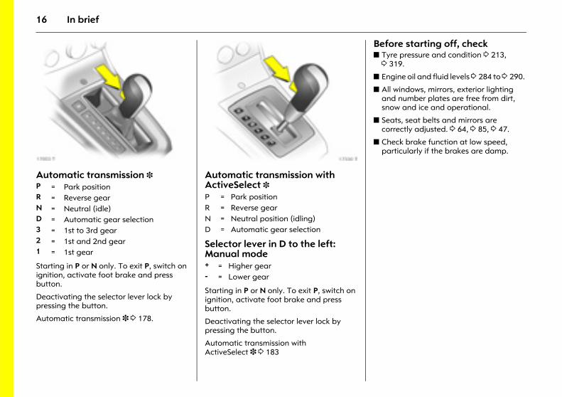
Picture no: 17003t.tifAutomatic transmission 3
Starting in P or N only. To exit P, switch on ignition, activate foot brake and press button.
Deactivating the selector lever lock by pressing the button.
Automatic transmission 3 3 178.
Picture no: 17330t.tifAutomatic transmission with ActiveSelect 3
Selector lever in D to the left:Manual mode
Starting in P or N only. To exit P, switch on ignition, activate foot brake and press button.
Deactivating the selector lever lock by pressing the button.
Automatic transmission with ActiveSelect 3 3 183
Before starting off, check z Tyre pressure and condition 3 213,
3 319.
z Engine oil and fluid levels 3 284 to 3 290.
z All windows, mirrors, exterior lighting and number plates are free from dirt, snow and ice and operational.
z Seats, seat belts and mirrors are correctly adjusted. 3 64, 3 85, 3 47.
z Check brake function at low speed, particularly if the brakes are damp.
P = Park positionR = Reverse gearN = Neutral (idle)D = Automatic gear selection3 = 1st to 3rd gear2 = 1st and 2nd gear1 = 1st gear
P = Park positionR = Reverse gearN = Neutral position (idling)D = Automatic gear selection
+ = Higher gear- = Lower gear
17In brief
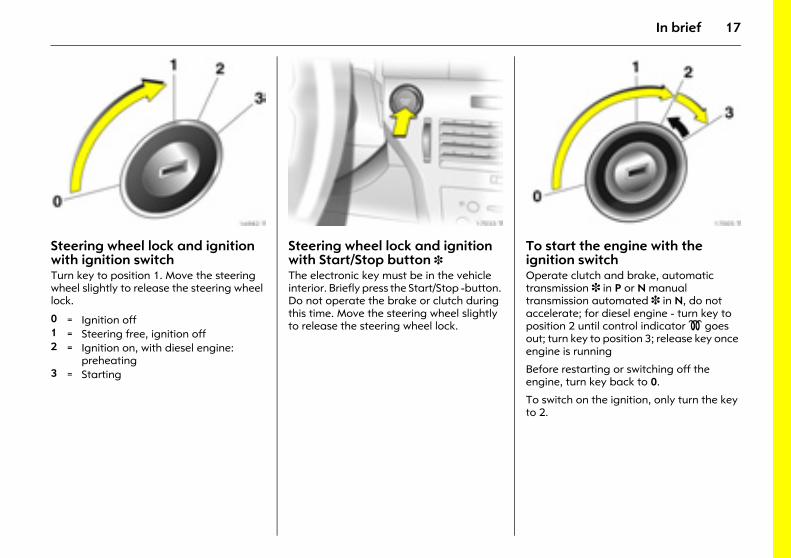
Picture no: 16982t.tifSteering wheel lock and ignition with ignition switchTurn key to position 1. Move the steering wheel slightly to release the steering wheel lock.
Picture no: 17033t.tifSteering wheel lock and ignition with Start/Stop button 3The electronic key must be in the vehicle interior. Briefly press the Start/Stop -button. Do not operate the brake or clutch during this time. Move the steering wheel slightly to release the steering wheel lock.
Picture no: 17005t.tifTo start the engine with the ignition switchOperate clutch and brake, automatic transmission 3 in P or N manual transmission automated 3 in N, do not accelerate; for diesel engine - turn key to position 2 until control indicator ! goes out; turn key to position 3; release key once engine is running
Before restarting or switching off the engine, turn key back to 0.
To switch on the ignition, only turn the key to 2.
0 = Ignition off1 = Steering free, ignition off2 = Ignition on, with diesel engine:
preheating 3 = Starting
18 In brief
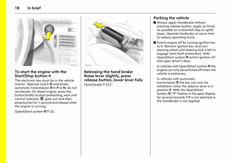
Picture no: 17033t.tifTo start the engine with the Start/Stop button 3 The electronic key must be in the vehicle interior. Operate clutch 3 and brake, automatic transmission 3 in P or N, do not accelerate; for diesel engine, press the button briefly to start preheating, wait until control indicator ! goes out and then press button for 1 second and release when the engine is running.
Open&Start system 3 3 32.
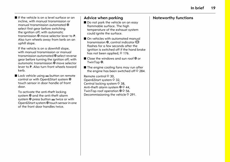
Picture no: 17006t.tifReleasing the hand brake: Raise lever slightly, press release button, lower lever fully Hand brake 3 212.
Parking the vehicle z Always apply handbrake without
pressing release button. Apply as firmly as possible on a downhill slop or uphill slope. Operate footbrake at same time to reduce operating force.
z Switch engine off by turning ignition key to 0. Remove ignition key and turn steering wheel until steering lock is felt to engage (anti-theft protection). With Open&Start system 3 switch ignition off and open driver’s door.
In vehicles with Open&Start system 3 the engine can only be switched off when the vehicle is stationary.
In vehicles with automatic transmission 3 the key can only be withdrawn when the selector lever is in position P. With the Open&Start System 3, "P" flashes in the gear display for several seconds if P is not selected or the handbrake is not applied.
19In brief
z If the vehicle is on a level surface or an incline, with manual transmission or manual transmission automated 3 select first gear before switching the ignition off; with automatic transmission 3 move selector lever to P. Also turn wheels away from kerb on an uphill slope.
If the vehicle is on a downhill slope, with manual transmission or manual transmission automated 3 select reverse gear before turning the ignition off; with automatic transmission 3 move selector lever to P. Also turn front wheels toward kerb.
z Lock vehicle using p button on remote control or with Open&Start system 3 touch sensor in door handle of front door.
To activate the anti-theft locking system 3 and the anti-theft alarm system 3 press button p twice or with Open&Start system 3 touch sensor in one of the front door handles twice.
Advice when parking z Do not park the vehicle on an easy
flammable surface. The high temperature of the exhaust system could ignite the surface.
z On vehicles with automated manual transmission 3, control indicator R flashes for a few seconds after the ignition is switched off if the hand brake has not been applied, 3 176.
z Close the windows and sun roof 3 or TwinTop 3.
z The engine cooling fans may run after the engine has been switched off 3 284.
Remote control 3 30, Open&Start system 3 32, Central locking system 3 38, Anti-theft alarm system 3 3 44, TwinTop roof operation 3 3 56. Decommissioning the vehicle 3 291.
Noteworthy functions
20 In brief
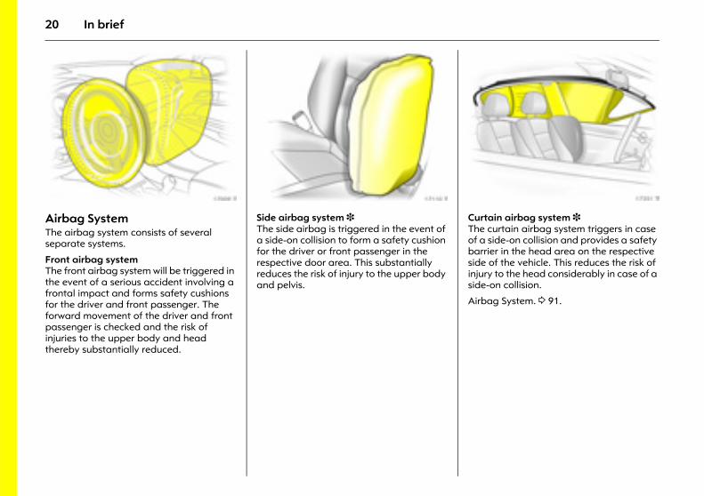
Picture no: 17009t.tifAirbag System The airbag system consists of several separate systems.
Front airbag system The front airbag system will be triggered in the event of a serious accident involving a frontal impact and forms safety cushions for the driver and front passenger. The forward movement of the driver and front passenger is checked and the risk of injuries to the upper body and head thereby substantially reduced.
Picture no: 17110t.tifSide airbag system 3 The side airbag is triggered in the event of a side-on collision to form a safety cushion for the driver or front passenger in the respective door area. This substantially reduces the risk of injury to the upper body and pelvis.
Picture no: 17351t.tifCurtain airbag system 3 The curtain airbag system triggers in case of a side-on collision and provides a safety barrier in the head area on the respective side of the vehicle. This reduces the risk of injury to the head considerably in case of a side-on collision.
Airbag System. 3 91.
21In brief
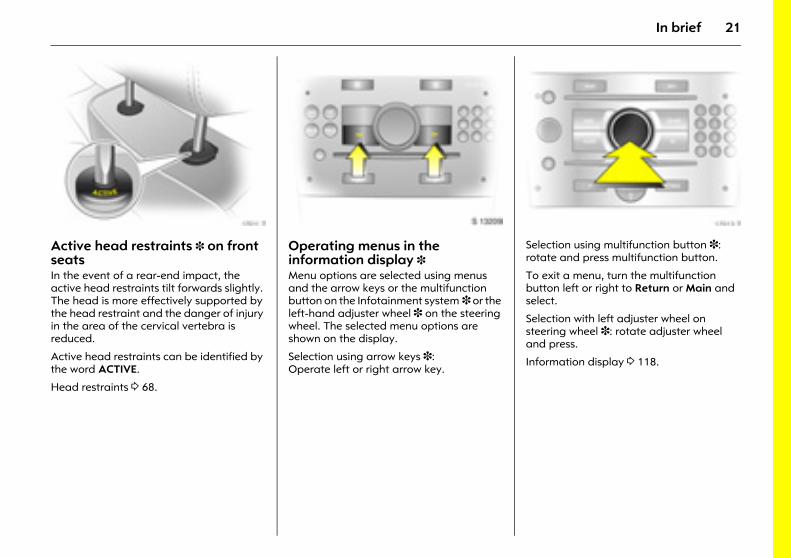
Picture no: 17011t.tifActive head restraints 3 on front seats In the event of a rear-end impact, the active head restraints tilt forwards slightly. The head is more effectively supported by the head restraint and the danger of injury in the area of the cervical vertebra is reduced.
Active head restraints can be identified by the word ACTIVE.
Head restraints 3 68.
Picture no: S0013209.tifOperating menus in the information display 3 Menu options are selected using menus and the arrow keys or the multifunction button on the Infotainment system 3 or the left-hand adjuster wheel 3 on the steering wheel. The selected menu options are shown on the display.
Selection using arrow keys 3: Operate left or right arrow key.
Picture no: 17013t.tifSelection using multifunction button 3: rotate and press multifunction button.
To exit a menu, turn the multifunction button left or right to Return or Main and select.
Selection with left adjuster wheel on steering wheel 3: rotate adjuster wheel and press.
Information display 3 118.
22 In brief
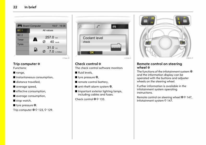
Picture no: 17344t.tifTrip computer 3 Functions:
z range,
z instantaneous consumption,
z distance travelled,
z average speed,
z effective consumption,
z average consumption,
z stop watch,
z tyre pressure 3.
Trip computer 3 3 123, 3 129.
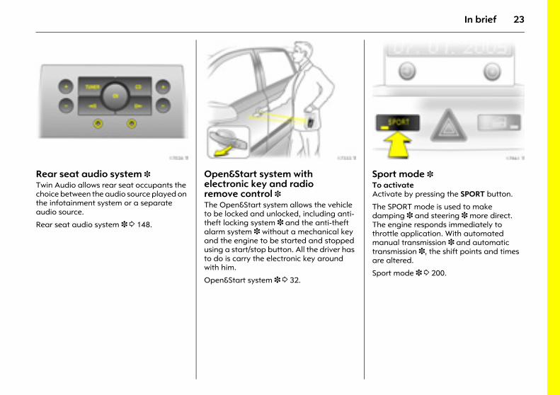
Picture no: 17339t.tifCheck control 3 The check control software monitors
z fluid levels,
z tyre pressure 3,
z remote control battery,
z anti-theft alarm system 3,
z Important exterior lighting lamps, including cables and fuses.
Check control 3 3 133.
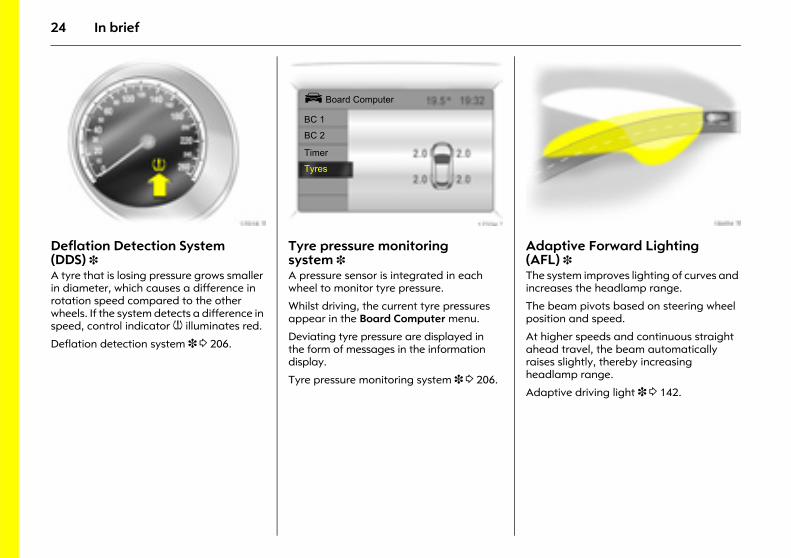
Picture no: 17015t.tifRemote control on steering wheel 3 The functions of the infotainment system 3 and the information display can be operated with the buttons and adjuster wheels on the steering wheel.
Further information is available in the infotainment system operating instructions.
Remote control on steering wheel 3 3 147, Infotainment system 3 147.
Ü Board Computer 19,5° 19:36
BC 1 All values
BC 2257.0 km
TimerØ 40 km/h
Tyres31.0 Ltr.
Ø 7.0 L/100km
1
8
Coolant levelcheck
OK
23In brief
Picture no: 17026t.tifRear seat audio system 3 Twin Audio allows rear seat occupants the choice between the audio source played on the infotainment system or a separate audio source.
Rear seat audio system 3 3 148.
Picture no: 17333t.tifOpen&Start system with electronic key and radio remove control 3 The Open&Start system allows the vehicle to be locked and unlocked, including anti-theft locking system 3 and the anti-theft alarm system 3 without a mechanical key and the engine to be started and stopped using a start/stop button. All the driver has to do is carry the electronic key around with him.
Open&Start system 3 3 32.
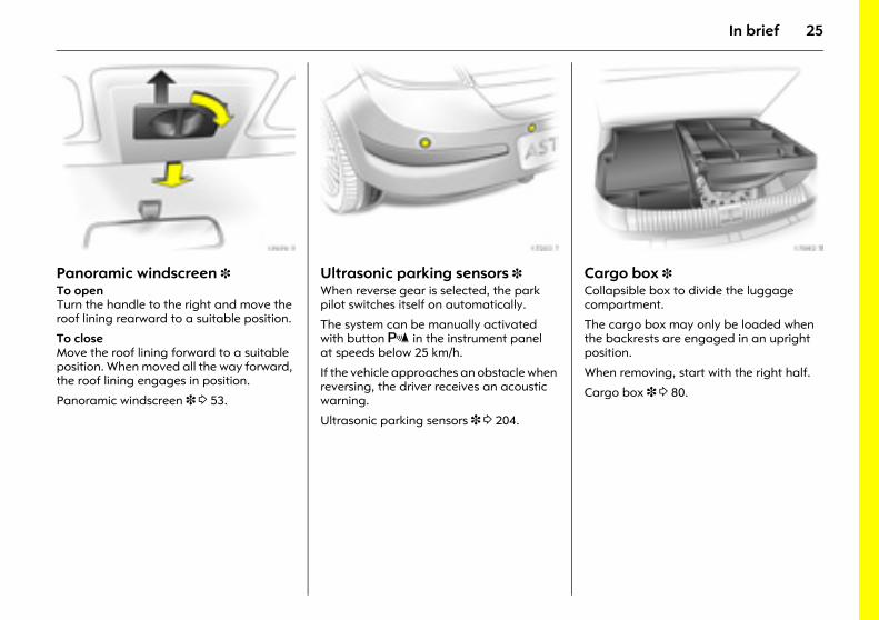
Picture no: 17961t.tifSport mode 3 To activateActivate by pressing the SPORT button.
The SPORT mode is used to make damping 3 and steering 3 more direct. The engine responds immediately to throttle application. With automated manual transmission 3 and automatic transmission 3, the shift points and times are altered.
Sport mode 3 3 200.
24 In brief
Picture no: 17018t.tifDeflation Detection System (DDS) 3 A tyre that is losing pressure grows smaller in diameter, which causes a difference in rotation speed compared to the other wheels. If the system detects a difference in speed, control indicator w illuminates red.
Deflation detection system 3 3 206.
Picture no: 17334t.tifTyre pressure monitoring system 3 A pressure sensor is integrated in each wheel to monitor tyre pressure.
Whilst driving, the current tyre pressures appear in the Board Computer menu.
Deviating tyre pressure are displayed in the form of messages in the information display.
Tyre pressure monitoring system 3 3 206.
Picture no: 18494t.tifAdaptive Forward Lighting (AFL) 3 The system improves lighting of curves and increases the headlamp range.
The beam pivots based on steering wheel position and speed.
At higher speeds and continuous straight ahead travel, the beam automatically raises slightly, thereby increasing headlamp range.
Adaptive driving light 3 3 142.
Ü Board Computer
BC 1
BC 2
Timer
Tyres
25In brief
Picture no: 17979t.tifPanoramic windscreen 3 To open Turn the handle to the right and move the roof lining rearward to a suitable position.
To close Move the roof lining forward to a suitable position. When moved all the way forward, the roof lining engages in position.
Panoramic windscreen 3 3 53.
Picture no: 17203t.tifUltrasonic parking sensors 3 When reverse gear is selected, the park pilot switches itself on automatically.
The system can be manually activated with button r in the instrument panel at speeds below 25 km/h.
If the vehicle approaches an obstacle when reversing, the driver receives an acoustic warning.
Ultrasonic parking sensors 3 3 204.
Picture no: 17092t.tifCargo box 3 Collapsible box to divide the luggage compartment.
The cargo box may only be loaded when the backrests are engaged in an upright position.
When removing, start with the right half.
Cargo box 3 3 80.
26 In brief
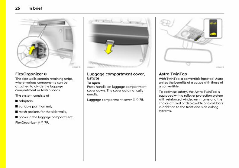
Picture no: 17087t.tifFlexOrganizer 3 The side walls contain retaining strips, where various components can be attached to divide the luggage compartment or fasten loads.
The system consists of
z adapters,
z variable partition net,
z mesh pockets for the side walls,
z hooks in the luggage compartment.
FlexOrganizer 3 3 79.
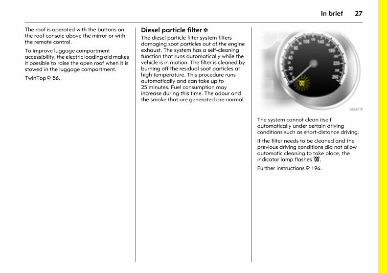
Picture no: 17980t.tifLuggage compartment cover, EstateTo open Press handle on luggage compartment cover down. The cover automatically unrolls.
Luggage compartment cover 3 3 75.
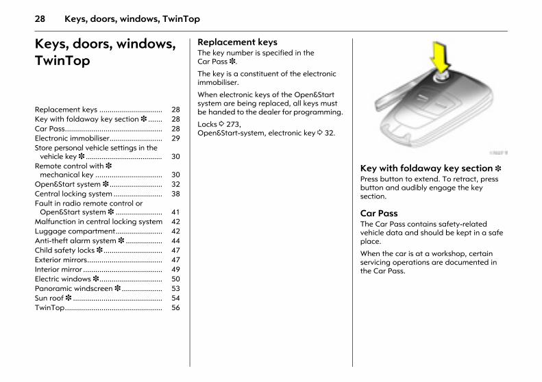
Picture no: 17981t.tifAstra TwinTop With TwinTop, a convertible hardtop, Astra unites the benefits of a coupe with those of a convertible.
To optimise safety, the Astra TwinTop is equipped with a rollover protection system with reinforced windscreen frame and the choice of fixed or deployable anti-roll bars in addition to the front and side airbag systems.
27In brief
The roof is operated with the buttons on the roof console above the mirror or with the remote control.
To improve luggage compartment accessibility, the electric loading aid makes it possible to raise the open roof when it is stowed in the luggage compartment.
TwinTop 3 56.
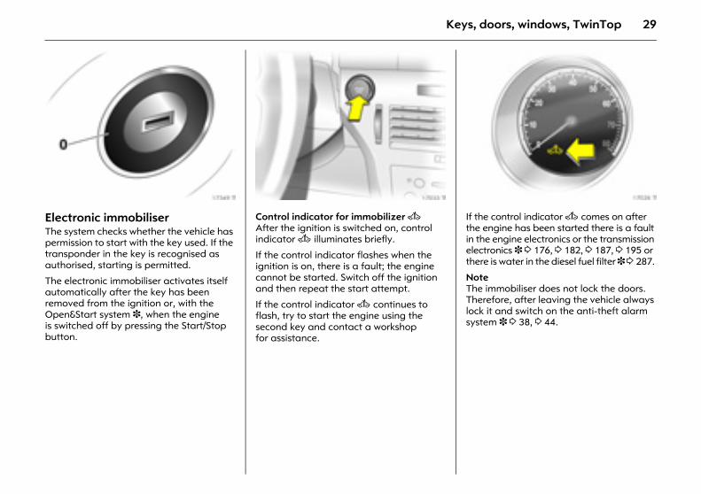
Diesel particle filter 3 The diesel particle filter system filters damaging soot particles out of the engine exhaust. The system has a self-cleaning function that runs automatically while the vehicle is in motion. The filter is cleaned by burning off the residual soot particles at high temperature. This procedure runs automatically and can take up to 25 minutes. Fuel consumption may increase during this time. The odour and the smoke that are generated are normal.
Picture no: 18537t.tifThe system cannot clean itself automatically under certain driving conditions such as short-distance driving.
If the filter needs to be cleaned and the previous driving conditions did not allow automatic cleaning to take place, the indicator lamp flashes !.
Further instructions 3 196.
28 Keys, doors, windows, TwinTop
Keys, doors, windows, TwinTop
Replacement keys The key number is specified in the Car Pass 3.
The key is a constituent of the electronic immobiliser.
When electronic keys of the Open&Start system are being replaced, all keys must be handed to the dealer for programming.
Locks 3 273, Open&Start-system, electronic key 3 32.
Picture no: 17027t.tifKey with foldaway key section 3 Press button to extend. To retract, press button and audibly engage the key section.
Car PassThe Car Pass contains safety-related vehicle data and should be kept in a safe place.
When the car is at a workshop, certain servicing operations are documented in the Car Pass.
Replacement keys ............................... 28 Key with foldaway key section 3 ....... 28 Car Pass................................................ 28 Electronic immobiliser.......................... 29 Store personal vehicle settings in the
vehicle key 3 ....................................... 30 Remote control with 3
mechanical key ................................. 30 Open&Start system 3 .......................... 32 Central locking system ........................ 38 Fault in radio remote control or
Open&Start system 3 ....................... 41 Malfunction in central locking system 42 Luggage compartment....................... 42 Anti-theft alarm system 3 .................. 44 Child safety locks 3 ............................. 47 Exterior mirrors..................................... 47 Interior mirror ....................................... 49 Electric windows 3 ............................... 50 Panoramic windscreen 3 .................... 53 Sun roof 3 ............................................ 54 TwinTop................................................ 56
29Keys, doors, windows, TwinTop
Picture no: 17349t.tifElectronic immobiliser The system checks whether the vehicle has permission to start with the key used. If the transponder in the key is recognised as authorised, starting is permitted.
The electronic immobiliser activates itself automatically after the key has been removed from the ignition or, with the Open&Start system 3, when the engine is switched off by pressing the Start/Stop button.
Picture no: 17033t.tifControl indicator for immobilizer A After the ignition is switched on, control indicator A illuminates briefly.
If the control indicator flashes when the ignition is on, there is a fault; the engine cannot be started. Switch off the ignition and then repeat the start attempt.
If the control indicator A continues to flash, try to start the engine using the second key and contact a workshop for assistance.
Picture no: 17028t.tifIf the control indicator A comes on after the engine has been started there is a fault in the engine electronics or the transmission electronics 3 3 176, 3 182, 3 187, 3 195 or there is water in the diesel fuel filter 3 3 287.
Note The immobiliser does not lock the doors. Therefore, after leaving the vehicle always lock it and switch on the anti-theft alarm system 3 3 38, 3 44.
30 Keys, doors, windows, TwinTop
Store personal vehicle settings in the vehicle key 3 The last settings selected
z instrument illumination,
z information display 3,
z Infotainment system 3,
z for the climate control system 3
are stored automatically upon locking depending on the vehicle key used.
The stored settings are automatically called up when the vehicle is unlocked.
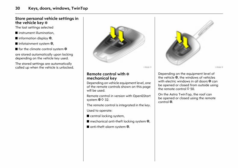
Picture no: 17029t.tifRemote control with 3 mechanical key Depending on vehicle equipment level, one of the remote controls shown on this page will be used.
Remote control in version with Open&Start system 3 3 32.
The remote control is integrated in the key.
Used to operate:
z central locking system,
z mechanical anti-theft locking system 3,
z anti-theft alarm system 3.
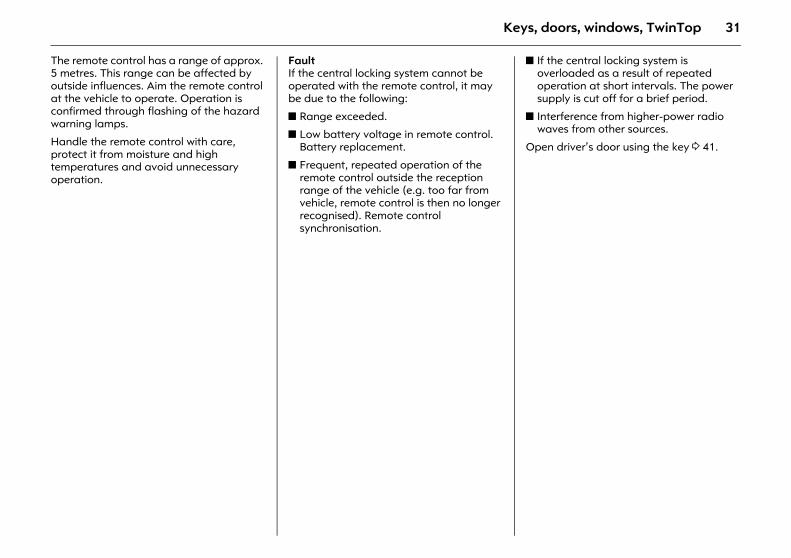
Picture no: 17030t.tifDepending on the equipment level of the vehicle 3, the windows of vehicles with electric windows in all doors 3 can be opened or closed from outside using the remote control 3 50.
On the Astra TwinTop, the roof can be opened or closed using the remote control 3.
31Keys, doors, windows, TwinTop
The remote control has a range of approx. 5 metres. This range can be affected by outside influences. Aim the remote control at the vehicle to operate. Operation is confirmed through flashing of the hazard warning lamps.
Handle the remote control with care, protect it from moisture and high temperatures and avoid unnecessary operation.
Fault If the central locking system cannot be operated with the remote control, it may be due to the following:
z Range exceeded.
z Low battery voltage in remote control. Battery replacement.
z Frequent, repeated operation of the remote control outside the reception range of the vehicle (e.g. too far from vehicle, remote control is then no longer recognised). Remote control synchronisation.
z If the central locking system is overloaded as a result of repeated operation at short intervals. The power supply is cut off for a brief period.
z Interference from higher-power radio waves from other sources.
Open driver’s door using the key 3 41.
32 Keys, doors, windows, TwinTop
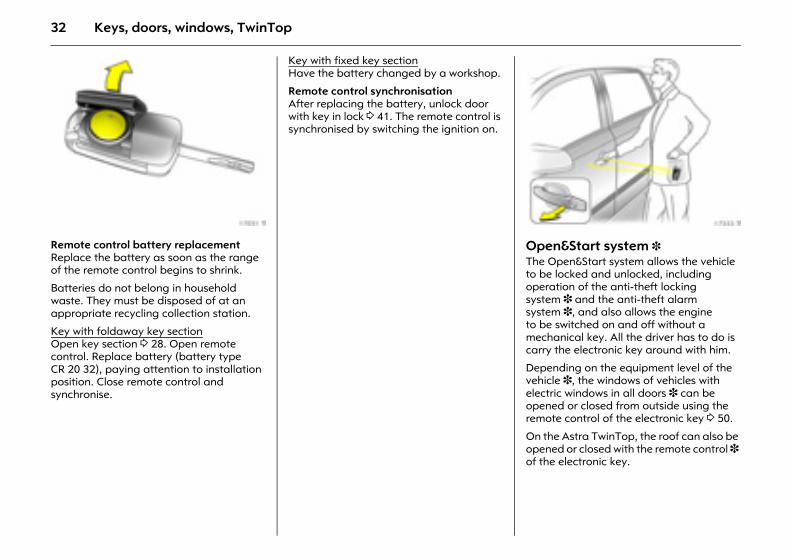
Picture no: 17031t.tifRemote control battery replacement Replace the battery as soon as the range of the remote control begins to shrink.
Batteries do not belong in household waste. They must be disposed of at an appropriate recycling collection station.
Key with foldaway key sectionOpen key section 3 28. Open remote control. Replace battery (battery type CR 20 32), paying attention to installation position. Close remote control and synchronise.
Key with fixed key sectionHave the battery changed by a workshop.
Remote control synchronisation After replacing the battery, unlock door with key in lock 3 41. The remote control is synchronised by switching the ignition on.
Picture no: 17333t.tifOpen&Start system 3 The Open&Start system allows the vehicle to be locked and unlocked, including operation of the anti-theft locking system 3 and the anti-theft alarm system 3, and also allows the engine to be switched on and off without a mechanical key. All the driver has to do is carry the electronic key around with him.
Depending on the equipment level of the vehicle 3, the windows of vehicles with electric windows in all doors 3 can be opened or closed from outside using the remote control of the electronic key 3 50.
On the Astra TwinTop, the roof can also be opened or closed with the remote control 3 of the electronic key.
33Keys, doors, windows, TwinTop
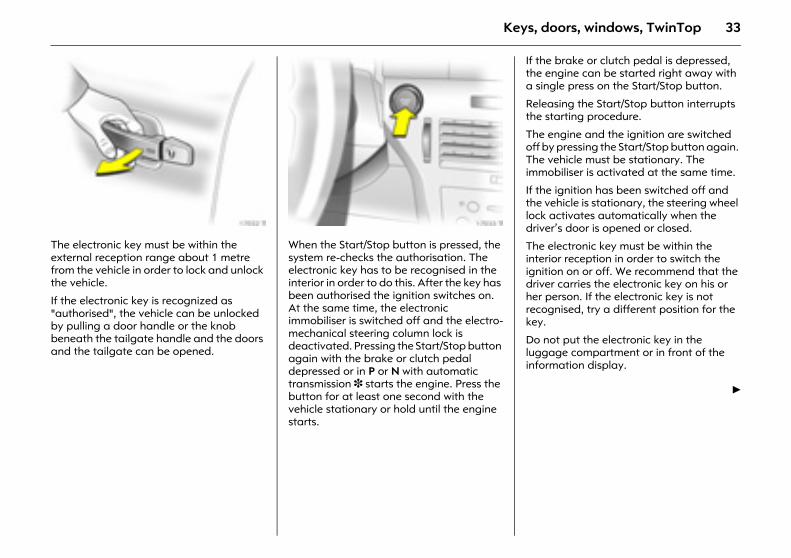
Picture no: 17032t.tifThe electronic key must be within the external reception range about 1 metre from the vehicle in order to lock and unlock the vehicle.
If the electronic key is recognized as "authorised", the vehicle can be unlocked by pulling a door handle or the knob beneath the tailgate handle and the doors and the tailgate can be opened.
Picture no: 17033t.tifWhen the Start/Stop button is pressed, the system re-checks the authorisation. The electronic key has to be recognised in the interior in order to do this. After the key has been authorised the ignition switches on. At the same time, the electronic immobiliser is switched off and the electro-mechanical steering column lock is deactivated. Pressing the Start/Stop button again with the brake or clutch pedal depressed or in P or N with automatic transmission 3 starts the engine. Press the button for at least one second with the vehicle stationary or hold until the engine starts.
If the brake or clutch pedal is depressed, the engine can be started right away with a single press on the Start/Stop button.
Releasing the Start/Stop button interrupts the starting procedure.
The engine and the ignition are switched off by pressing the Start/Stop button again. The vehicle must be stationary. The immobiliser is activated at the same time.
If the ignition has been switched off and the vehicle is stationary, the steering wheel lock activates automatically when the driver’s door is opened or closed.
The electronic key must be within the interior reception in order to switch the ignition on or off. We recommend that the driver carries the electronic key on his or her person. If the electronic key is not recognised, try a different position for the key.
Do not put the electronic key in the luggage compartment or in front of the information display.
6
34 Keys, doors, windows, TwinTop
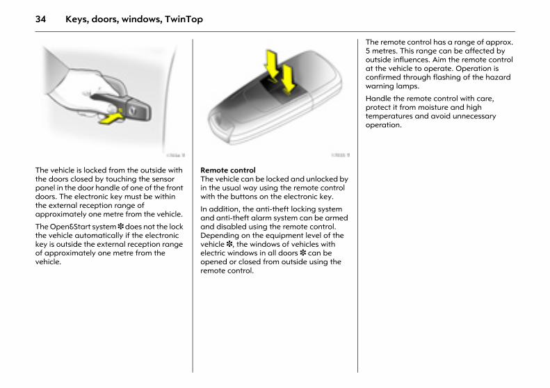
Picture no: 17034t.tifThe vehicle is locked from the outside with the doors closed by touching the sensor panel in the door handle of one of the front doors. The electronic key must be within the external reception range of approximately one metre from the vehicle.
The Open&Start system 3 does not the lock the vehicle automatically if the electronic key is outside the external reception range of approximately one metre from the vehicle.
Picture no: 17035t.tifRemote control The vehicle can be locked and unlocked by in the usual way using the remote control with the buttons on the electronic key.
In addition, the anti-theft locking system and anti-theft alarm system can be armed and disabled using the remote control. Depending on the equipment level of the vehicle 3, the windows of vehicles with electric windows in all doors 3 can be opened or closed from outside using the remote control.
The remote control has a range of approx. 5 metres. This range can be affected by outside influences. Aim the remote control at the vehicle to operate. Operation is confirmed through flashing of the hazard warning lamps.
Handle the remote control with care, protect it from moisture and high temperatures and avoid unnecessary operation.
35Keys, doors, windows, TwinTop
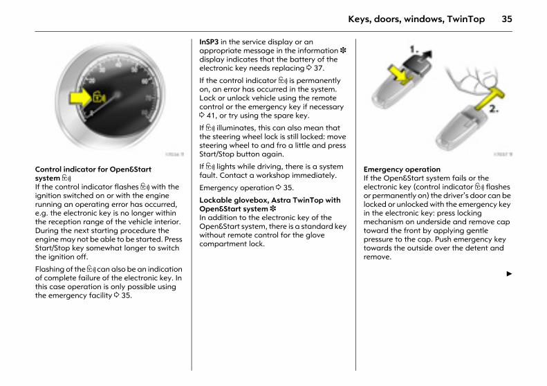
Picture no: 17036t.tifControl indicator for Open&Start system 0 If the control indicator flashes 0 with the ignition switched on or with the engine running an operating error has occurred, e.g. the electronic key is no longer within the reception range of the vehicle interior. During the next starting procedure the engine may not be able to be started. Press Start/Stop key somewhat longer to switch the ignition off.
Flashing of the 0 can also be an indication of complete failure of the electronic key. In this case operation is only possible using the emergency facility 3 35.
InSP3 in the service display or an appropriate message in the information 3 display indicates that the battery of the electronic key needs replacing 3 37.
If the control indicator 0 is permanently on, an error has occurred in the system. Lock or unlock vehicle using the remote control or the emergency key if necessary 3 41, or try using the spare key.
If 0 illuminates, this can also mean that the steering wheel lock is still locked: move steering wheel to and fro a little and press Start/Stop button again.
If 0 lights while driving, there is a system fault. Contact a workshop immediately.
Emergency operation 3 35.
Lockable glovebox, Astra TwinTop with Open&Start system 3 In addition to the electronic key of the Open&Start system, there is a standard key without remote control for the glove compartment lock.
Picture no: 17037t.tifEmergency operation If the Open&Start system fails or the electronic key (control indicator 0 flashes or permanently on) the driver’s door can be locked or unlocked with the emergency key in the electronic key: press locking mechanism on underside and remove cap toward the front by applying gentle pressure to the cap. Push emergency key towards the outside over the detent and remove.
6
36 Keys, doors, windows, TwinTop
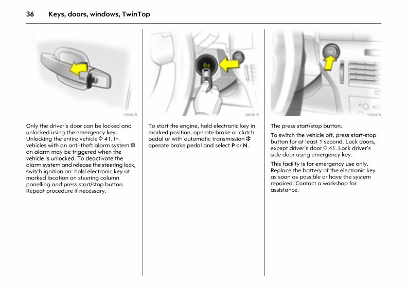
Picture no: 17038t.tifOnly the driver’s door can be locked and unlocked using the emergency key. Unlocking the entire vehicle 3 41. In vehicles with an anti-theft alarm system 3 an alarm may be triggered when the vehicle is unlocked. To deactivate the alarm system and release the steering lock, switch ignition on: hold electronic key at marked location on steering column panelling and press start/stop button. Repeat procedure if necessary.
Picture no: 18439t.tifTo start the engine, hold electronic key in marked position, operate brake or clutch pedal or with automatic transmission 3 operate brake pedal and select P or N.
Picture no: 17033t.tifThe press start/stop button.
To switch the vehicle off, press start-stop button for at least 1 second. Lock doors, except driver’s door 3 41. Lock driver’s side door using emergency key.
This facility is for emergency use only. Replace the battery of the electronic key as soon as possible or have the system repaired. Contact a workshop for assistance.
37Keys, doors, windows, TwinTop
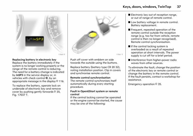
Picture no: 17040t.tifReplacing battery in electronic key Replace the battery immediately if the system is no longer working properly or the range of the remote control is reducing. The need for a battery change is indicated by InSP3 in the service display or, in vehicles with check control 3, by an appropriate message in the display 3 116.
To replace the battery, operate lock on underside of electronic key and remove cover by pushing gently forwards 3 35, Fig. 17037 T.
Picture no: 17041t.tifPush off cover with emblem on side towards the outside using the buttons.
Replace battery (battery type CR 20 32), noting installation position. Clip in covers and synchronise remote control.
Remote control synchronisation The remote control synchronises itself automatically during every starting procedure.
Fault in Open&Start system or remote control If the central locking cannot be operated or the engine cannot be started, the cause may be one of the following:
z Electronic key out of reception range, or out of range of remote control.
z Low battery voltage in remote control. Battery replacement.
z Frequent, repeated operation of the remote control outside the reception range (e.g. too far from vehicle, remote control is then no longer recognised). Remote control synchronisation.
z If the central locking system is overloaded as a result of repeated operation at short intervals. The power supply is cut off for a brief period.
z Interference from higher-power radio waves from other sources.
To eliminate the fault, change the position of the electronic key or remote control or change the battery in the remote control. If the fault persists, contact a workshop for assistance.
Emergency operation 3 35.
38 Keys, doors, windows, TwinTop
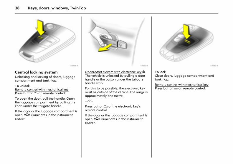
Picture no: 16968t.tifCentral locking system Unlocking and locking of doors, luggage compartment and tank flap.
To unlock Remote control with mechanical keyPress button q on remote control.
To open the door, pull the handle. Open the luggage compartment by pulling the knob under the tailgate handle.
If the door or the luggage compartment is open, Q illuminates in the instrument cluster.
Picture no: 17032t.tifOpen&Start system with electronic key 3 The vehicle is unlocked by pulling a door handle or the button under the tailgate handle strip.
For this to be possible, the electronic key must be outside of the vehicle. The range is approximately one metre.
– or –
Press button q of the electronic key’s remote control.
If the door or the luggage compartment is open, Q illuminates in the instrument cluster.
Picture no: 17042t.tifTo lock Close doors, luggage compartment and tank flap.
Remote control with mechanical keyPress button p on remote control.
39Keys, doors, windows, TwinTop
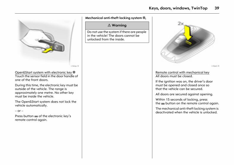
Picture no: 17034t.tifOpen&Start system with electronic key 3 Touch the sensor field in the door handle of one of the front doors.
During this time, the electronic key must be outside of the vehicle. The range is approximately one metre. No other key must be inside the vehicle.
The Open&Start system does not lock the vehicle automatically.
– or –
Press button p of the electronic key’s remote control again.
Mechanical anti-theft locking system 3,
Picture no: 17043t.tifRemote control with mechanical keyAll doors must be closed.
If the ignition was on, the driver’s door must be opened and closed once so that the vehicle can be secured.
All doors are secured against opening.
Within 15 seconds of locking, press the p button on the remote control again.
The mechanical anti-theft locking system is deactivated when the vehicle is unlocked.
9 Warning
Do not use the system if there are people in the vehicle! The doors cannot be unlocked from the inside.
40 Keys, doors, windows, TwinTop
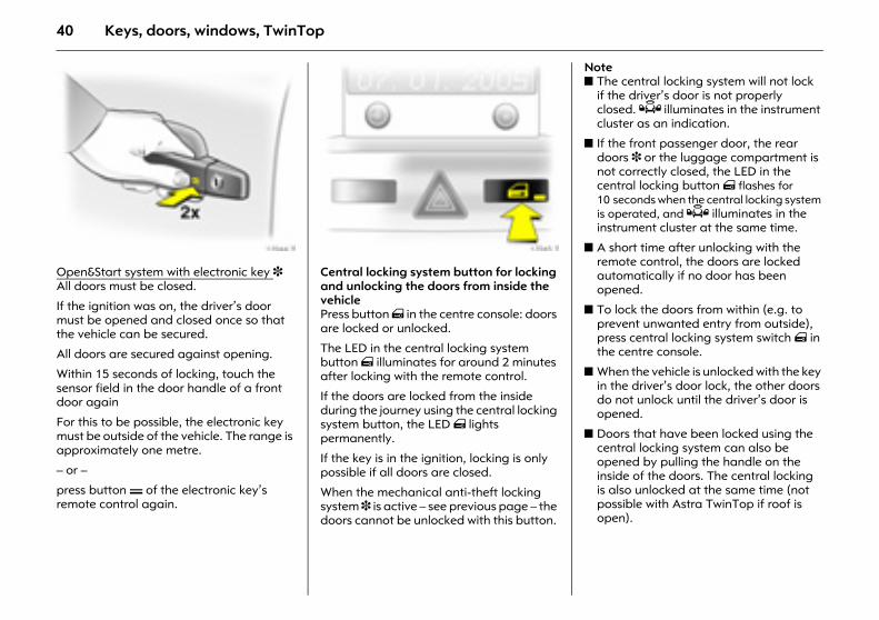
Picture no: 17044t.tifOpen&Start system with electronic key 3 All doors must be closed.
If the ignition was on, the driver’s door must be opened and closed once so that the vehicle can be secured.
All doors are secured against opening.
Within 15 seconds of locking, touch the sensor field in the door handle of a front door again
For this to be possible, the electronic key must be outside of the vehicle. The range is approximately one metre.
– or –
press button p of the electronic key’s remote control again.
Picture no: 17045t.tifCentral locking system button for locking and unlocking the doors from inside the vehiclePress button m in the centre console: doors are locked or unlocked.
The LED in the central locking system button m illuminates for around 2 minutes after locking with the remote control.
If the doors are locked from the inside during the journey using the central locking system button, the LED m lights permanently.
If the key is in the ignition, locking is only possible if all doors are closed.
When the mechanical anti-theft locking system 3 is active – see previous page – the doors cannot be unlocked with this button.
Note z The central locking system will not lock
if the driver’s door is not properly closed. Q illuminates in the instrument cluster as an indication.
z If the front passenger door, the rear doors 3 or the luggage compartment is not correctly closed, the LED in the central locking button m flashes for 10 seconds when the central locking system is operated, and Q illuminates in the instrument cluster at the same time.
z A short time after unlocking with the remote control, the doors are locked automatically if no door has been opened.
z To lock the doors from within (e.g. to prevent unwanted entry from outside), press central locking system switch m in the centre console.
z When the vehicle is unlocked with the key in the driver’s door lock, the other doors do not unlock until the driver’s door is opened.
z Doors that have been locked using the central locking system can also be opened by pulling the handle on the inside of the doors. The central locking is also unlocked at the same time (not possible with Astra TwinTop if roof is open).
41Keys, doors, windows, TwinTop
z Locked doors unlock automatically in the event of an accident of a certain severity (to allow external help to gain access). The hazard warning lamps and courtesy lamp also come on. For this to occur, the key must be in the ignition switch.
z With the Open&Start system 3 the vehicle cannot be unlocked until 2 seconds after locking. Within this time, a door handle can be pulled or the button beneath the tailgate handle operated to check whether the vehicle is locked.
z The Open&Start system 3 does not lock the vehicle automatically if the electronic key is outside the reception range of the vehicle (more than 1 metre away from the vehicle).
z When using the Open&Start system 3, there must not be an electronic key inside the vehicle when locking.
z The locking sensors in the door handles must be kept clean to ensure unrestricted functionality of the Open&Start system 3.
Fault If the central locking system cannot be operated, it may be due to the following:
z If the central locking system is overloaded as a result of repeated operation at short intervals. The power supply is cut off for a brief period.
z Faulty fuse in fuse box 3 246.
Contact a workshop to have the cause of the fault remedied.
For operating the driver’s door with the key, see following section.
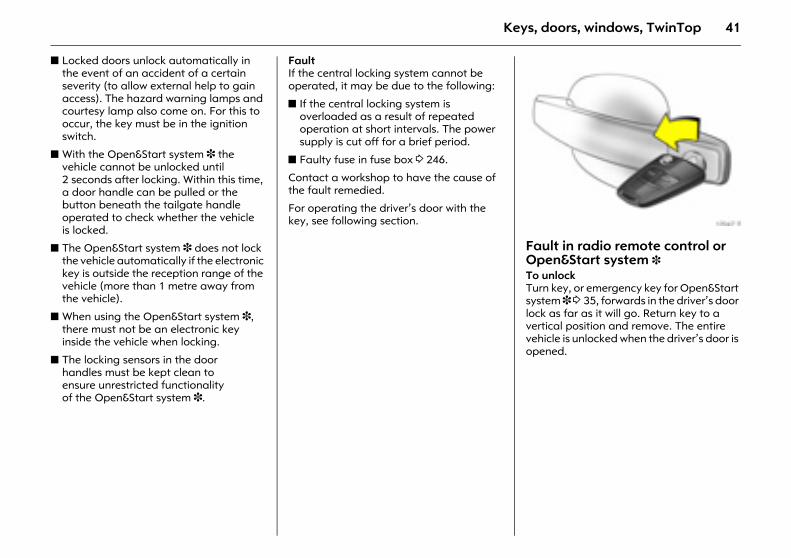
Picture no: 17047t.tifFault in radio remote control or Open&Start system 3 To unlockTurn key, or emergency key for Open&Start system 3 3 35, forwards in the driver’s door lock as far as it will go. Return key to a vertical position and remove. The entire vehicle is unlocked when the driver’s door is opened.
42 Keys, doors, windows, TwinTop
For Astra TwinTop with open roof - after opening the driver’s door, press the central locking button m in the centre console. The vehicle will then be unlocked, provided the anti-theft locking system 3 is not engaged. Switch on the ignition to deactivate the anti-theft alarm system 3. Emergency operation of the Open&Start system 3 3 35.
To lock Open passenger door, close driver’s door, press central locking button m in centre console. Central locking system locks all doors. Close passenger door.
Malfunction in central locking system To unlock With Open&Start system 3 3 35, turn key or emergency key forwards in the driver’s door lock as far as it will go. Return key to vertical position and remove. The other doors can be opened by pulling the handle on the inside of the doors (not possible if anti-theft locking system 3 was activated beforehand). Luggage compartment and tank flap remain locked. To deactivate the anti-theft alarm system 3 switch ignition on 3 44.
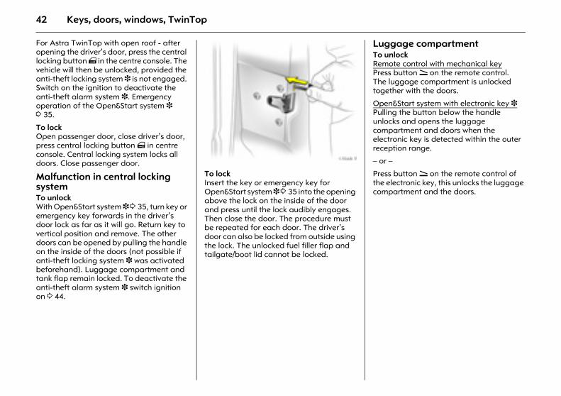
Picture no: 17048t.tifTo lock Insert the key or emergency key for Open&Start system 3 3 35 into the opening above the lock on the inside of the door and press until the lock audibly engages. Then close the door. The procedure must be repeated for each door. The driver’s door can also be locked from outside using the lock. The unlocked fuel filler flap and tailgate/boot lid cannot be locked.
Luggage compartment To unlock Remote control with mechanical keyPress button q on the remote control. The luggage compartment is unlocked together with the doors.
Open&Start system with electronic key 3 Pulling the button below the handle unlocks and opens the luggage compartment and doors when the electronic key is detected within the outer reception range.
– or –
Press button q on the remote control of the electronic key, this unlocks the luggage compartment and the doors.
43Keys, doors, windows, TwinTop
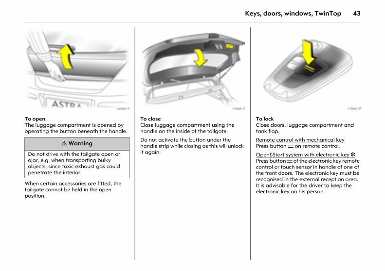
Picture no: 16969t.tifTo open The luggage compartment is opened by operating the button beneath the handle.
When certain accessories are fitted, the tailgate cannot be held in the open position.
Picture no: 17049t.tifTo close Close luggage compartment using the handle on the inside of the tailgate.
Do not activate the button under the handle strip while closing as this will unlock it again.
Picture no: 17042t.tifTo lock Close doors, luggage compartment and tank flap.
Remote control with mechanical keyPress button p on remote control.
Open&Start system with electronic key 3 Press button p of the electronic key remote control or touch sensor in handle of one of the front doors. The electronic key must be recognised in the external reception area. It is advisable for the driver to keep the electronic key on his person.
9 Warning
Do not drive with the tailgate open or ajar, e.g. when transporting bulky objects, since toxic exhaust gas could penetrate the interior.
44 Keys, doors, windows, TwinTop
Anti-theft alarm system 3 monitors
z the doors, luggage compartment, bonnet,
z the passenger compartment,
z vehicle tilt, e.g. if it is raised,
z the ignition.
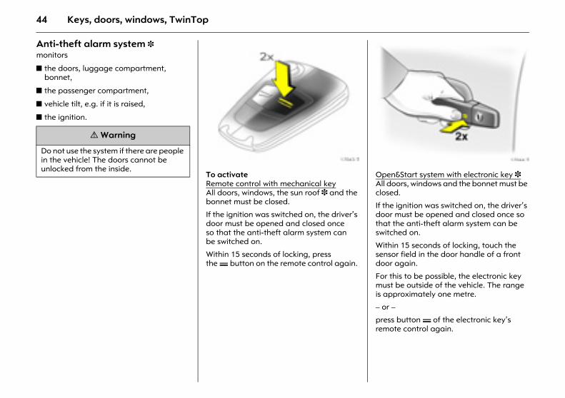
Picture no: 17043t.tifTo activate Remote control with mechanical keyAll doors, windows, the sun roof 3 and the bonnet must be closed.
If the ignition was switched on, the driver’s door must be opened and closed once so that the anti-theft alarm system can be switched on.
Within 15 seconds of locking, press the p button on the remote control again.
Picture no: 17044t.tifOpen&Start system with electronic key 3 All doors, windows and the bonnet must be closed.
If the ignition was switched on, the driver’s door must be opened and closed once so that the anti-theft alarm system can be switched on.
Within 15 seconds of locking, touch the sensor field in the door handle of a front door again.
For this to be possible, the electronic key must be outside of the vehicle. The range is approximately one metre.
– or –
press button p of the electronic key’s remote control again.
9 Warning
Do not use the system if there are people in the vehicle! The doors cannot be unlocked from the inside.
45Keys, doors, windows, TwinTop
Picture no: 17050t.tifActivation without monitoring of passenger compartment and vehicle tilt To activate e. g. if animals are left in the vehicle.
1. Close tailgate and bonnet.
2. Press button b in the roof console. The LED in button m flashes (max. 10 seconds), see next page.
3. Close doors.
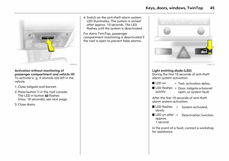
4. Switch on the anti-theft alarm system. LED illuminates. The system is armed after approx. 10 seconds. The LED flashes until the system is deactivated.
For Astra TwinTop, passenger compartment monitoring is deactivated if the roof is open to prevent false alarms.
Picture no: 17051t.tifLight emitting diode (LED) During the first 10 seconds of anti-theft alarm system activation:
After the first 10 seconds of anti-theft alarm system activation:
In the event of a fault, contact a workshop for assistance.
z LED on = Test, activation delay, z LED flashes
quickly= Door, tailgate or bonnet
open, or system fault.
z LED flashes slowly
= System activated,
z LED on after approx. 1 second
= Deactivation function.
46 Keys, doors, windows, TwinTop
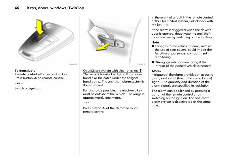
Picture no: 16968t.tifTo deactivate Remote control with mechanical keyPress button q on remote control
– or –
Switch on ignition.
Picture no: 17032t.tifOpen&Start system with electronic key 3 The vehicle is unlocked by pulling a door handle or the catch under the tailgate handle strip. The anti-theft alarm system is then disabled.
For this to be possible, the electronic key must be outside of the vehicle. The range is approximately one metre.
– or –
Press button q of the electronic key’s remote control.
In the event of a fault in the remote control or the Open&Start system, unlock door with the key 3 41.
If the alarm is triggered when the driver’s door is opened, deactivate the anti-theft alarm system by switching on the ignition.
Note z Changes to the vehicle interior, such as
the use of seat covers, could impair the function of passenger compartment monitoring.
z Disengage interior monitoring if the interior of the parked vehicle is heated.
Alarm If triggered, the alarm provides an acoustic (horn) and visual (hazard warning lamps) signal. The quantity and duration of the alarm signals are specified in legislation.
The alarm can be silenced by pressing a button of the remote control or by switching on the ignition. The anti-theft alarm system is deactivated at the same time.
47Keys, doors, windows, TwinTop
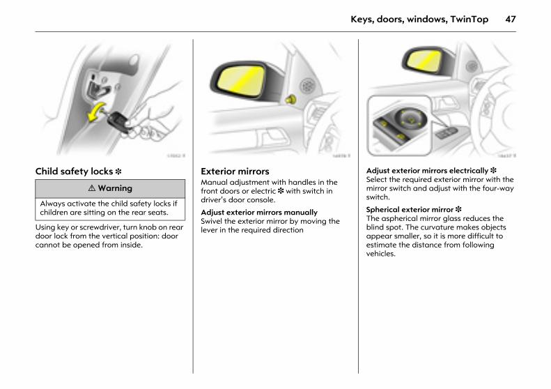
Picture no: 17052t.tifChild safety locks 3
Using key or screwdriver, turn knob on rear door lock from the vertical position: door cannot be opened from inside.
Picture no: 16978t.tifExterior mirrors Manual adjustment with handles in the front doors or electric 3 with switch in driver’s door console.
Adjust exterior mirrors manually Swivel the exterior mirror by moving the lever in the required direction
Picture no: 18437t.tifAdjust exterior mirrors electrically 3 Select the required exterior mirror with the mirror switch and adjust with the four-way switch.
Spherical exterior mirror 3 The aspherical mirror glass reduces the blind spot. The curvature makes objects appear smaller, so it is more difficult to estimate the distance from following vehicles.
9 Warning
Always activate the child safety locks if children are sitting on the rear seats.
48 Keys, doors, windows, TwinTop
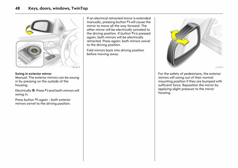
Picture no: 18438t.tifSwing in exterior mirror Manual: The exterior mirrors can be swung in by pressing on the outside of the housing.
Electrically 3: Press n and both mirrors will swing in.
Press button n again - both exterior mirrors swivel to the driving position.
If an electrical retracted mirror is extended manually, pressing button n will cause the mirror to move all the way forward. The other mirror will be electrically swiveled to the driving position. If button n is pressed again, both mirrors will be electrically retracted. Press again: both mirrors swivel to the driving position.
Fold mirrors back into driving position before moving away.
Picture no: 17120t.tifFor the safety of pedestrians, the exterior mirrors will swing out of their normal mounting position if they are bumped with sufficient force. Reposition the mirror by applying slight pressure to the mirror housing.
49Keys, doors, windows, TwinTop
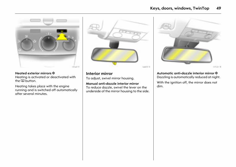
Picture no: 17147t.tifHeated exterior mirrors 3 Heating is activated or deactivated with the Ü button.
Heating takes place with the engine running and is switched off automatically after several minutes.
Picture no: 16977t.tifInterior mirror To adjust, swivel mirror housing.
Manual anti-dazzle interior mirror To reduce dazzle, swivel the lever on the underside of the mirror housing to the side.
Picture no: 17121t.tifAutomatic anti-dazzle interior mirror 3 Dazzling is automatically reduced at night.
With the ignition off, the mirror does not dim.
50 Keys, doors, windows, TwinTop
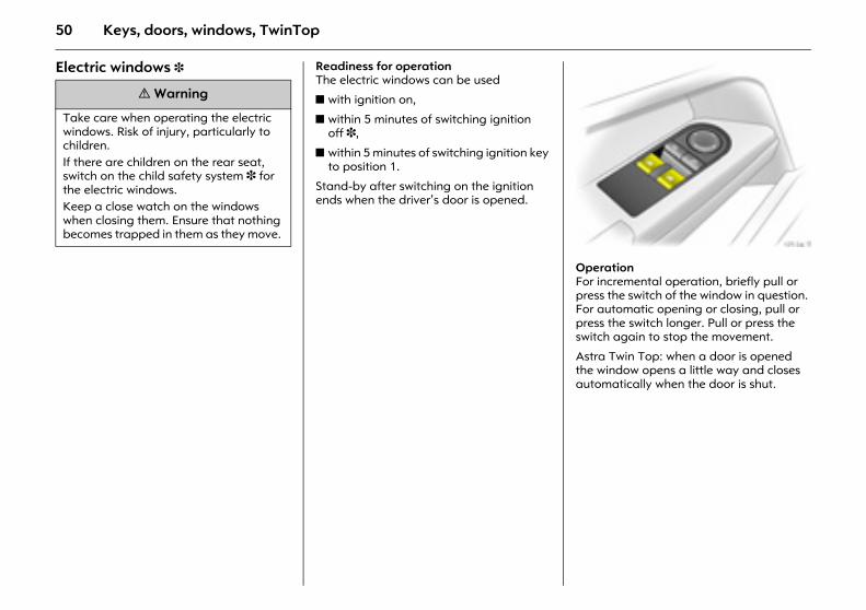
Electric windows 3 Readiness for operation The electric windows can be used
z with ignition on,
z within 5 minutes of switching ignition off 3,
z within 5 minutes of switching ignition key to position 1.
Stand-by after switching on the ignition ends when the driver’s door is opened.
Picture no: 17134t.tifOperationFor incremental operation, briefly pull or press the switch of the window in question. For automatic opening or closing, pull or press the switch longer. Pull or press the switch again to stop the movement.
Astra Twin Top: when a door is opened the window opens a little way and closes automatically when the door is shut.
9 Warning
Take care when operating the electric windows. Risk of injury, particularly to children. If there are children on the rear seat, switch on the child safety system 3 for the electric windows. Keep a close watch on the windows when closing them. Ensure that nothing becomes trapped in them as they move.
51Keys, doors, windows, TwinTop
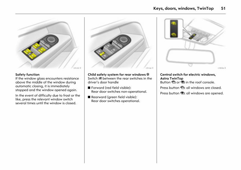
Picture no: 17135t.tifSafety function If the window glass encounters resistance above the middle of the window during automatic closing, it is immediately stopped and the window opened again.
In the event of difficulty due to frost or the like, press the relevant window switch several times until the window is closed.
Picture no: 17136t.tifChild safety system for rear windows 3 Switch z between the rear switches in the driver’s door handle
z Forward (red field visible): Rear door switches non-operational.
z Rearward (green field visible): Rear door switches operational.
Picture no: 17976t.tifCentral switch for electric windows, Astra TwinTop Button $ or " in the roof console.
Press button $: all windows are closed.
Press button ": all windows are opened.
52 Keys, doors, windows, TwinTop
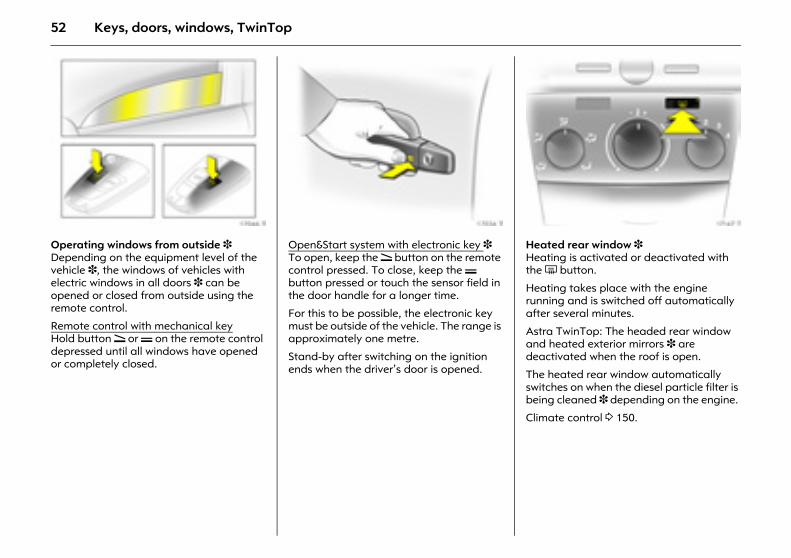
Picture no: 17046t.tifOperating windows from outside 3 Depending on the equipment level of the vehicle 3, the windows of vehicles with electric windows in all doors 3 can be opened or closed from outside using the remote control.
Remote control with mechanical keyHold button q or p on the remote control depressed until all windows have opened or completely closed.
Picture no: 17034t.tifOpen&Start system with electronic key 3 To open, keep the q button on the remote control pressed. To close, keep the p button pressed or touch the sensor field in the door handle for a longer time.
For this to be possible, the electronic key must be outside of the vehicle. The range is approximately one metre.
Stand-by after switching on the ignition ends when the driver’s door is opened.
Picture no: 17147t.tifHeated rear window 3 Heating is activated or deactivated with the Ü button.
Heating takes place with the engine running and is switched off automatically after several minutes.
Astra TwinTop: The headed rear window and heated exterior mirrors 3 are deactivated when the roof is open.
The heated rear window automatically switches on when the diesel particle filter is being cleaned 3 depending on the engine.
Climate control 3 150.
53Keys, doors, windows, TwinTop
Overload If the windows are repeatedly operated at short intervals, the power supply is briefly cut off.
Fault If the windows cannot be opened and closed automatically because of an interruption to the power supply, for example, activate electric windows as follows:
1. Close doors.
2. Switch on ignition.
3. Close the window all the way and hold the button depressed at least 5 seconds.
4. Open the window all the way and hold the button depressed at least 1 second longer.
5. Repeat for each window.
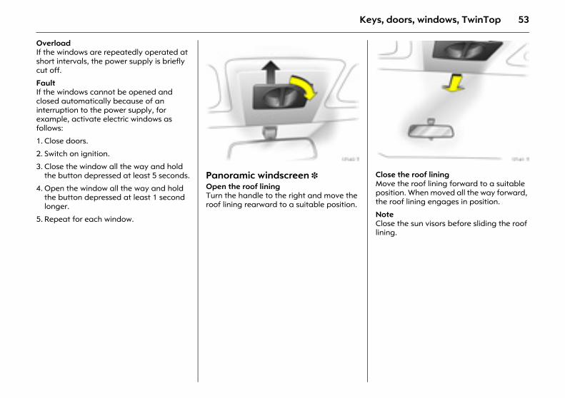
Picture no: 17140t.tifPanoramic windscreen 3 Open the roof lining Turn the handle to the right and move the roof lining rearward to a suitable position.
Picture no: 17141t.tifClose the roof lining Move the roof lining forward to a suitable position. When moved all the way forward, the roof lining engages in position.
Note Close the sun visors before sliding the roof lining.
54 Keys, doors, windows, TwinTop
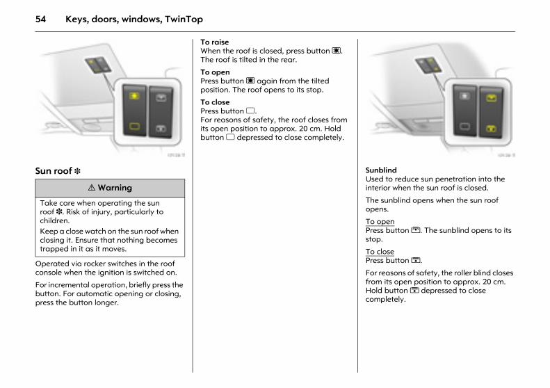
Picture no: 17138t.tifSun roof 3
Operated via rocker switches in the roof console when the ignition is switched on.
For incremental operation, briefly press the button. For automatic opening or closing, press the button longer.
To raise When the roof is closed, press button ü. The roof is tilted in the rear.
To open Press button ü again from the tilted position. The roof opens to its stop.
To close Press button d. For reasons of safety, the roof closes from its open position to approx. 20 cm. Hold button d depressed to close completely.
Picture no: 17139t.tifSunblind Used to reduce sun penetration into the interior when the sun roof is closed.
The sunblind opens when the sun roof opens.
To open Press button G. The sunblind opens to its stop.
To close Press button H.
For reasons of safety, the roller blind closes from its open position to approx. 20 cm. Hold button H depressed to close completely.
9 Warning
Take care when operating the sun roof 3. Risk of injury, particularly to children. Keep a close watch on the sun roof when closing it. Ensure that nothing becomes trapped in it as it moves.
55Keys, doors, windows, TwinTop
Note z If the top of the roof is wet, raise roof,
allow water to run off and then open roof.
z When using a roof rack, check the clearance of the sun roof to avoid damage.
Overload If the system is overloaded, the power supply is automatically cut off for a short time.
The system is protected by fuses in the fuse box 3 246.
Fault If the sun roof and sun shade do not operate properly, activate electronics as follows:
1. Switch on ignition.
2. Close the sun roof and hold button d depressed at least 10 seconds.
3. Close sunblind and hold button H depressed at least 10 seconds.
56 Keys, doors, windows, TwinTop
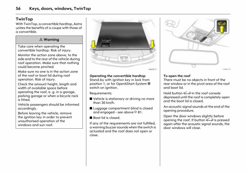
TwinTop With TwinTop, a convertible hardtop, Astra unites the benefits of a coupe with those of a convertible.
Picture no: 18620T.tifOperating the convertible hardtopStand-by with ignition key in lock from position 1, or for Open&Start-System 3 switch on ignition.
Requirements:
z Vehicle is stationary or driving no more than 30 km/h.
z Luggage compartment blind is closed and engaged - see above 3 81.
z Boot lid is closed.
If any of the requirements are not fulfilled, a warning buzzer sounds when the switch is actuated and the roof does not open or close.
Picture no: 17962t.tifTo open the roof There must be no objects in front of the rear window or in the pivot area of the roof and boot lid.
Hold button > in the roof console depressed until the roof is completely open and the boot lid is closed.
An acoustic signal sounds at the end of the opening procedure.
Open the door windows slightly before opening the roof. If button > is pressed again after the acoustic signal sounds, the door windows will close.
9 Warning
Take care when operating the convertible hardtop. Risk of injury. Monitor the action zone above, to the side and to the rear of the vehicle during roof operation. Make sure that nothing could become pinched. Make sure no one is in the action zone of the roof or boot lid during roof operation. Risk of injury. Check the amount height, length and width of available space before operating the roof, e. g. in a garage, parking garage or when a bicycle rack is fitted. Vehicle passengers should be informed accordingly. Before leaving the vehicle, remove the ignition key in order to prevent unauthorised operation of the windows and sun roof.
57Keys, doors, windows, TwinTop
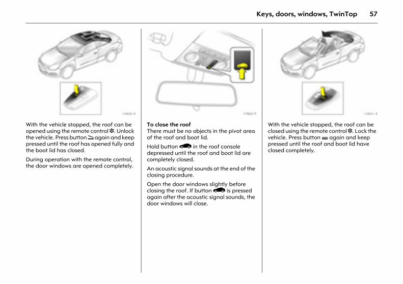
Picture no: 17970t.tifWith the vehicle stopped, the roof can be opened using the remote control 3. Unlock the vehicle. Press button q again and keep pressed until the roof has opened fully and the boot lid has closed.
During operation with the remote control, the door windows are opened completely.
Picture no: 17963t.tifTo close the roof There must be no objects in the pivot area of the roof and boot lid.
Hold button < in the roof console depressed until the roof and boot lid are completely closed.
An acoustic signal sounds at the end of the closing procedure.
Open the door windows slightly before closing the roof. If button < is pressed again after the acoustic signal sounds, the door windows will close.
Picture no: 17971t.tifWith the vehicle stopped, the roof can be closed using the remote control 3. Lock the vehicle. Press button p again and keep pressed until the roof and boot lid have closed completely.
58 Keys, doors, windows, TwinTop
Indicator and warning buzzers z Indicator buzzer upon completed
opening or closing of the convertible hardtop.
z Indicator buzzer upon completed raising or lowering of the electric luggage compartment loading aid.
z Gong tone if the boot lid is not closed during roof operation.
z Gong tone if the boot lid is not fully opening during operation of the luggage compartment loading aid.
z Gong tone during roof operation if vehicle speed exceeds 30 km/h.
z Gong tone when vehicle speed exceeds 30 km/h if the roof is not fully open or closed.
z Three gong tones during roof or loading aid operation if the luggage compartment blind is not attached.
z Three gong tones during roof operation if outside temperature is below –20 °C, vehicle battery voltage is too low or the system is overloaded.
z Continuous warning buzzer during roof operation if the anti-roll bars 3 have been triggered.
z Continuous warning buzzer starting one minute before the end of the 9-minute standby time with the roof in an intermediate position.
z Continuous warning buzzer starting one minute before the end of the 9-minute standby time with the loading aid in a raised position.
z Continuous warning buzzer when closing the boot lid if the lowering process of the electric load aid is not complete or was interrupted.
Note z Do not open the luggage compartment
until the acoustic signal indicating the end of the roof opening or closing procedure has sounded.
z The luggage compartment blind must always be closed during roof operation.
z There must be no one at the covers behind the rear head restraints.
z There must be no objects in the pivot area or the roof or on the covers behind the rear head restraints.
z The roof can only be operated at temperatures above –20 °C. If the temperature is below this limit, a gong will sound three times when roof operation is requested.
z Frequent operation of the roof with the engine off discharges the battery.
z Repeated operation of the roof without breaks can cause overloading and therefore malfunctions.
59Keys, doors, windows, TwinTop
z The roof can be held in an intermediate position for 9 minutes to facilitate cleaning of roof spaces. This is done by disengaging the actuation switch. One minute before the end of this period, a continuous buzzer sounds as a warning that the hold period is almost over and the roof could start to move.
z Activating the roof on uneven ground can lead to malfunctions and damage.
Fault The automatic drive of the roof is only operational if the roof is in the proper open or closed position.
Check if:
z The luggage compartment blind is engaged in the closed position.
z The boot lid is completely closed.
z Outside temperature is above –20 °C.
z There is sufficient battery voltage.
z There is a system overload.
If the automatic drive is not operational, two persons are required to manually close the roof. See the accompanying instructions for Astra TwinTop. We recommend that you seek professional assistance.
Rollover protection system To optimise safety in the event of a rollover, the Astra TwinTop is equipped with reinforced windscreen frame and anti-roll bars behind the rear sat head restraints. The anti-roll bars are fixed or deployable depending on vehicle variant.
60 Keys, doors, windows, TwinTop
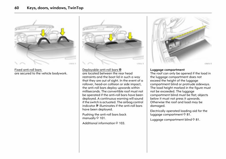
Picture no: 17975t.tifFixed anti-roll bars are secured to the vehicle bodywork.
Picture no: 17974t.tifDeployable anti-roll bars 3 are located between the rear head restraints and the boot lid in such a way that they are out of sight. In the event of a rollover, head-on collision or side impact, the anti-roll bars deploy upwards within milliseconds. The convertible roof must not be operated if the anti-roll bars have been deployed. A continuous warning will sound if the switch is actuated. The airbag control indicator v illuminates if the anti-roll bars have been deployed.
Pushing the anti-roll bars back manually 3 101.
Additional information 3 103.
Picture no: 17973t.tifLuggage compartment The roof can only be opened if the load in the luggage compartment does not exceed the height of the luggage compartment blind or protrude sideways. The load height marked in the figure must not be exceeded. The luggage compartment blind must be flat; objects below it must not press it upwards. Otherwise the roof and load may be damaged.
Electrically operated loading aid for the luggage compartment 3 81.
Luggage compartment blind 3 81.
61Keys, doors, windows, TwinTop
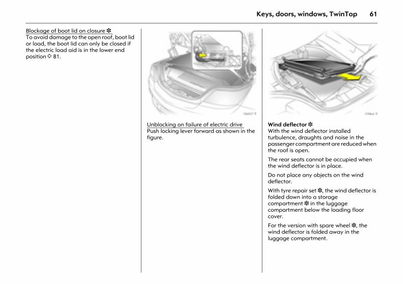
Blockage of boot lid on closure 3 To avoid damage to the open roof, boot lid or load, the boot lid can only be closed if the electric load aid is in the lower end position 3 81.
Picture no: 18457t.tifUnblocking on failure of electric drive Push locking lever forward as shown in the figure.
Picture no: 17964t.tifWind deflector 3 With the wind deflector installed turbulence, draughts and noise in the passenger compartment are reduced when the roof is open.
The rear seats cannot be occupied when the wind deflector is in place.
Do not place any objects on the wind deflector.
With tyre repair set 3, the wind deflector is folded down into a storage compartment 3 in the luggage compartment below the loading floor cover.
For the version with spare wheel 3, the wind deflector is folded away in the luggage compartment.
62 Keys, doors, windows, TwinTop
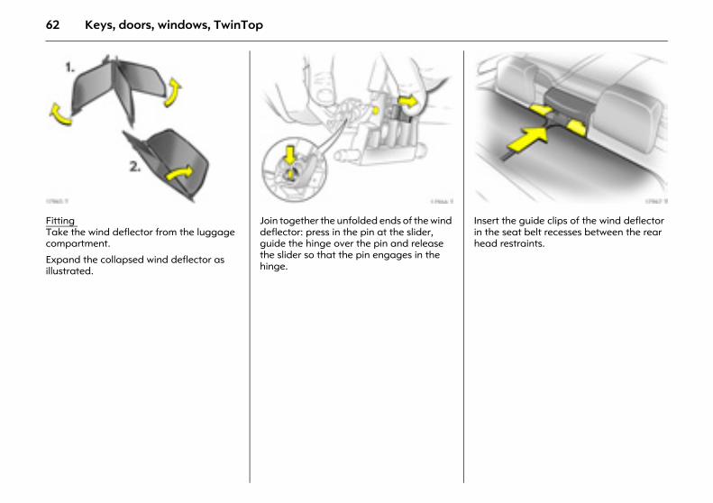
Picture no: 17965t.tifFitting Take the wind deflector from the luggage compartment.
Expand the collapsed wind deflector as illustrated.
Picture no: 17966t.tifJoin together the unfolded ends of the wind deflector: press in the pin at the slider, guide the hinge over the pin and release the slider so that the pin engages in the hinge.
Picture no: 17967t.tifInsert the guide clips of the wind deflector in the seat belt recesses between the rear head restraints.
63Keys, doors, windows, TwinTop
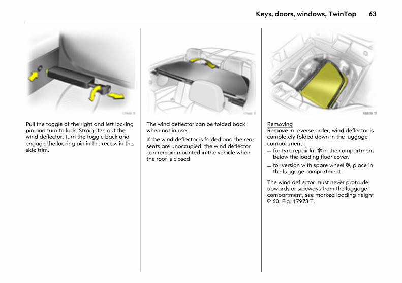
Picture no: 17968t.tifPull the toggle of the right and left locking pin and turn to lock. Straighten out the wind deflector, turn the toggle back and engage the locking pin in the recess in the side trim.
Picture no: 17969t.tifThe wind deflector can be folded back when not in use.
If the wind deflector is folded and the rear seats are unoccupied, the wind deflector can remain mounted in the vehicle when the roof is closed.
Picture no: 18619t.tifRemovingRemove in reverse order, wind deflector is completely folded down in the luggage compartment:
The wind deflector must never protrude upwards or sideways from the luggage compartment, see marked loading height 3 60, Fig. 17973 T.
– for tyre repair kit 3 in the compartment below the loading floor cover.
– for version with spare wheel 3, place in the luggage compartment.

64 Seats, interior
Seats, interior
Picture no: 16970t.tifFront seats
Adjust foot room of seatPull the handle on the front seat, slide the seat and release the handle.
Front seats ........................................... 64 Head restraints .................................... 68 Armrest 3 ............................................. 70 Extending the luggage compartment,
Saloon ................................................ 71 Extending the luggage compartment,
Estate ................................................. 72 Extending the luggage compartment,
Astra TwinTop................................... 74 Tilt front passenger seat backrest
forward 3........................................... 75 Luggage compartment cover ............ 75 Safety net 3, Estate............................. 77 Luggage compartment grille 3,
Delivery Van ...................................... 78 Lashing eyes 3 .................................... 79 Rails and hooks in the luggage
compartment 3, Estate .................... 79 FlexOrganizer 3................................... 79 Cargo box 3......................................... 80 Luggage compartment blind,
Astra TwinTop................................... 81 Easy Load............................................. 81 Notes on loading the vehicle.............. 83 Three-stage safety system.................. 84 Three-point seat belts ......................... 85 Belt tensioners...................................... 85
Operating the seat belts..................... 87 Child restraint system 3...................... 88 Airbag system...................................... 91 Rollover protection system 3 ............. 101 Cigarette lighter 3............................... 103 Accessory sockets 3 ............................ 104 Ashtray 3 ............................................. 105 Foldaway tables 3 .............................. 106 Stowage compartments ..................... 106 Stowage nets and pockets 3 ............. 107 Drinks holders 3 .................................. 107 Sun visors ............................................. 107
9 Warning
Never adjust seats while driving as they could move uncontrollably.
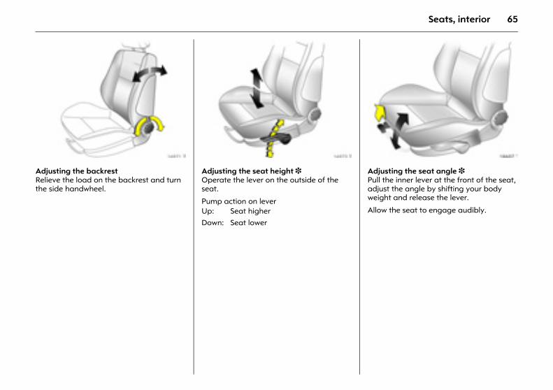
65Seats, interior
Picture no: 16971t.tifAdjusting the backrestRelieve the load on the backrest and turn the side handwheel.
Picture no: 16973t.tifAdjusting the seat height 3Operate the lever on the outside of the seat.
Pump action on lever
Picture no: 18607t.tifAdjusting the seat angle 3 Pull the inner lever at the front of the seat, adjust the angle by shifting your body weight and release the lever.
Allow the seat to engage audibly. Up: Seat higherDown: Seat lower
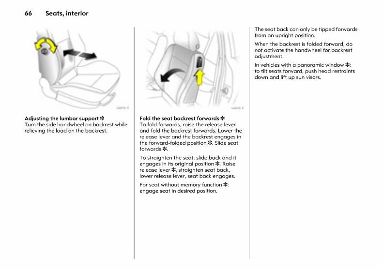
66 Seats, interior
Picture no: 16972t.tifAdjusting the lumbar support 3Turn the side handwheel on backrest while relieving the load on the backrest.
Picture no: 16975t.tifFold the seat backrest forwards 3 To fold forwards, raise the release lever and fold the backrest forwards. Lower the release lever and the backrest engages in the forward-folded position 3. Slide seat forwards 3.
To straighten the seat, slide back and it engages in its original position 3. Raise release lever 3, straighten seat back, lower release lever, seat back engages.
For seat without memory function 3: engage seat in desired position.
The seat back can only be tipped forwards from an upright position.
When the backrest is folded forward, do not activate the handwheel for backrest adjustment.
In vehicles with a panoramic window 3: to tilt seats forward, push head restraints down and lift up sun visors.
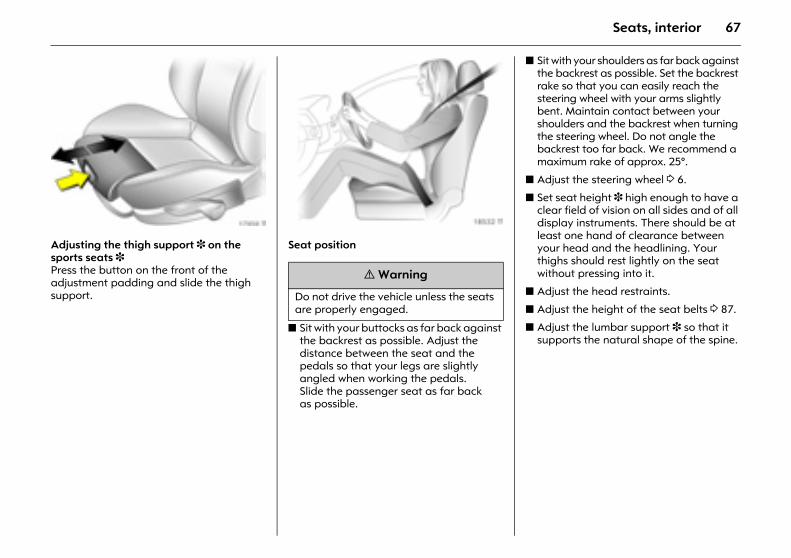
67Seats, interior
Picture no: 17959t.tifAdjusting the thigh support 3 on the sports seats 3Press the button on the front of the adjustment padding and slide the thigh support.
Picture no: 18532t.tifSeat position
z Sit with your buttocks as far back against the backrest as possible. Adjust the distance between the seat and the pedals so that your legs are slightly angled when working the pedals. Slide the passenger seat as far back as possible.
z Sit with your shoulders as far back against the backrest as possible. Set the backrest rake so that you can easily reach the steering wheel with your arms slightly bent. Maintain contact between your shoulders and the backrest when turning the steering wheel. Do not angle the backrest too far back. We recommend a maximum rake of approx. 25°.
z Adjust the steering wheel 3 6.
z Set seat height 3 high enough to have a clear field of vision on all sides and of all display instruments. There should be at least one hand of clearance between your head and the headlining. Your thighs should rest lightly on the seat without pressing into it.
z Adjust the head restraints.
z Adjust the height of the seat belts 3 87.
z Adjust the lumbar support 3 so that it supports the natural shape of the spine.
9 Warning
Do not drive the vehicle unless the seats are properly engaged.
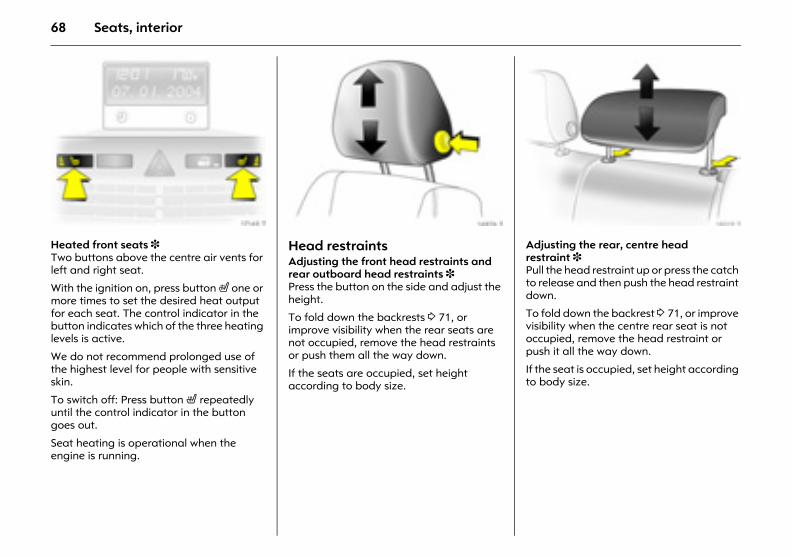
68 Seats, interior
Picture no: 17148t.tifHeated front seats 3 Two buttons above the centre air vents for left and right seat.
With the ignition on, press button ß one or more times to set the desired heat output for each seat. The control indicator in the button indicates which of the three heating levels is active.
We do not recommend prolonged use of the highest level for people with sensitive skin.
To switch off: Press button ß repeatedly until the control indicator in the button goes out.
Seat heating is operational when the engine is running.
Picture no: 16976t.tifHead restraintsAdjusting the front head restraints and rear outboard head restraints 3 Press the button on the side and adjust the height.
To fold down the backrests 3 71, or improve visibility when the rear seats are not occupied, remove the head restraints or push them all the way down.
If the seats are occupied, set height according to body size.
Picture no: 18019t.tifAdjusting the rear, centre head restraint 3 Pull the head restraint up or press the catch to release and then push the head restraint down.
To fold down the backrest 3 71, or improve visibility when the centre rear seat is not occupied, remove the head restraint or push it all the way down.
If the seat is occupied, set height according to body size.
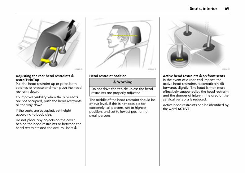
69Seats, interior
Picture no: 17983t.tifAdjusting the rear head restraints 3, Astra TwinTop Pull the head restraint up or press both catches to release and then push the head restraint down.
To improve visibility when the rear seats are not occupied, push the head restraints all the way down.
If the seats are occupied, set height according to body size.
Do not place any objects on the cover behind the head restraints or between the head restraints and the anti-roll bars 3.
Picture no: 17055t.tifHead restraint position
The middle of the head restraint should be at eye level. If this is not possible for extremely tall persons, set to highest position, and set to lowest position for small persons.
Picture no: 17011t.tifActive head restraints 3 on front seats In the event of a rear-end impact, the active head restraints automatically tilt forwards slightly. The head is then more effectively supported by the head restraint and the danger of injury in the area of the cervical vertebra is reduced.
Active head restraints can be identified by the word ACTIVE.
9 Warning
Do not drive the vehicle unless the head restraints are properly adjusted.
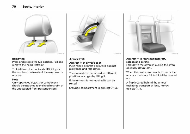
70 Seats, interior
Picture no: 17056t.tifRemoving Press and release the two catches. Pull and remove the head restraint.
To fold down the backrests 3 3 71, push the rear head restraints all the way down or remove.
NoteOnly approved objects or components should be attached to the head restraint of the unoccupied front passenger seat.
Picture no: 17058t.tifArmrest 3 Armrest 3 at driver’s seat Push raised armrest backward against resistance and fold down.
The armrest can be moved to different positions in stages by lifting it.
If the armrest is not required it can be raised.
Stowage compartment in armrest 3 106.
Picture no: 17060t.tifArmrest 3 in rear seat backrest, saloon and estateFold down the armrest, pulling the strap obliquely down (45°).
When the centre rear seat is in use or the rear backrests are folded, fold the armrest up.
A flap located behind the armrest facilitates transport of long, narrow objects 3 71.
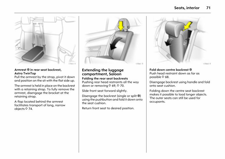
71Seats, interior
Picture no: 17982t.tifArmrest 3 in rear seat backrest, Astra TwinTop Pull the armrest by the strap, pivot it down and position on the sit with the flat side up.
The armrest is held in place on the backrest with a retaining strap. To fully remove the armrest, disengage the bracket at the retaining strap.
A flap located behind the armrest facilitates transport of long, narrow objects 3 74.
Picture no: 17061t.tifExtending the luggage compartment, Saloon Folding the rear seat backrests Pushing rear head restraints all the way down or removing 3 69, 3 70.
Slide front seat forward slightly.
Disengage the backrest (single or split 3) using the pushbutton and fold it down onto the seat cushion.
Return front seat to desired position.
Picture no: 17062t.tifFold down centre backrest 3Push head restraint down as far as possible 3 68.
Disengage backrest using handle and fold onto seat cushion.
Folding down the centre seat backrest makes it possible to load longer objects. The outer seats can still be used for occupants.
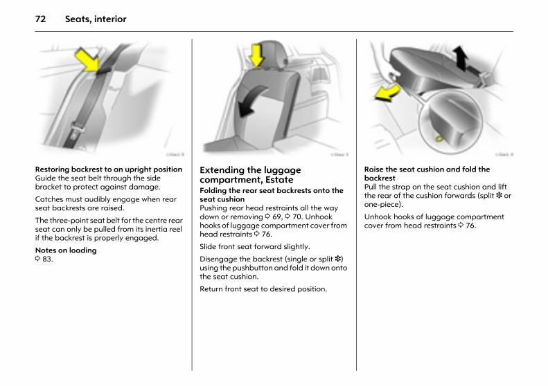
72 Seats, interior
Picture no: 17063t.tifRestoring backrest to an upright position Guide the seat belt through the side bracket to protect against damage.
Catches must audibly engage when rear seat backrests are raised.
The three-point seat belt for the centre rear seat can only be pulled from its inertia reel if the backrest is properly engaged.
Notes on loading 3 83.
Picture no: 17064t.tifExtending the luggage compartment, Estate Folding the rear seat backrests onto the seat cushion Pushing rear head restraints all the way down or removing 3 69, 3 70. Unhook hooks of luggage compartment cover from head restraints 3 76.
Slide front seat forward slightly.
Disengage the backrest (single or split 3) using the pushbutton and fold it down onto the seat cushion.
Return front seat to desired position.
Picture no: 17065t.tifRaise the seat cushion and fold the backrest Pull the strap on the seat cushion and lift the rear of the cushion forwards (split 3 or one-piece).
Unhook hooks of luggage compartment cover from head restraints 3 76.
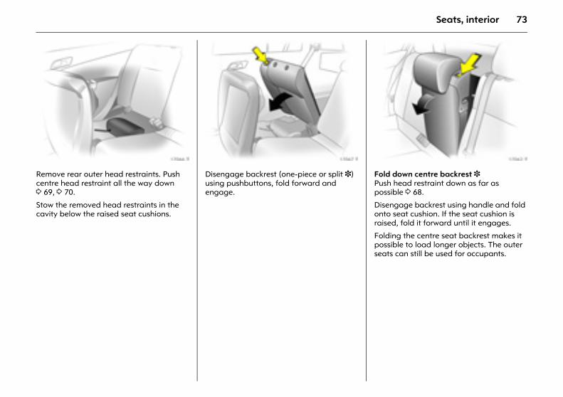
73Seats, interior
Picture no: 17066t.tifRemove rear outer head restraints. Push centre head restraint all the way down 3 69, 3 70.
Stow the removed head restraints in the cavity below the raised seat cushions.
Picture no: 17067t.tifDisengage backrest (one-piece or split 3) using pushbuttons, fold forward and engage.
Picture no: 17062t.tifFold down centre backrest 3Push head restraint down as far as possible 3 68.
Disengage backrest using handle and fold onto seat cushion. If the seat cushion is raised, fold it forward until it engages.
Folding the centre seat backrest makes it possible to load longer objects. The outer seats can still be used for occupants.
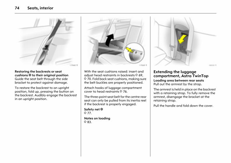
74 Seats, interior
Picture no: 17068t.tifRestoring the backrests or seat cushions 3 to their original position Guide the seat belt through the side bracket to protect against damage.
To restore the backrest to an upright position, fold up, pressing the button on the backrest. Audibly engage the backrest in an upright position.
Picture no: 17069t.tifWith the seat cushions raised: insert and adjust head restraints in backrests 3 69, 3 70. Fold back seat cushions, making sure the belt buckles are properly positioned.
Attach hooks of luggage compartment cover to head restraints 3 76.
The three-point seat belt for the centre rear seat can only be pulled from its inertia reel if the backrest is properly engaged.
Safety net 3 3 77.
Notes on loading 3 83.
Picture no: 18020t.tifExtending the luggage compartment, Astra TwinTopLoading area between rear seats Pull out the armrest by the strap.
The armrest is held in place on the backrest with a retaining strap. To fully remove the armrest, disengage the bracket at the retaining strap.
Pull the handle and fold down the cover.
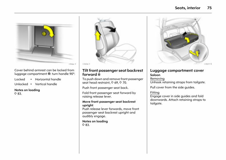
75Seats, interior
Picture no: 17984t.tifCover behind armrest can be locked from luggage compartment 3: turn handle 90°:
Notes on loading 3 83.
Picture no: 17076t.tifTilt front passenger seat backrest forward 3 To push down and remove front passenger seat head restraint, 3 69, 3 70.
Push front passenger seat back.
Fold front passenger seat forward by raising release lever.
Move front passenger seat backrest upright Push release lever forwards, move front passenger seat backrest upright and audibly engage.
Notes on loading 3 83.
Picture no: 17077t.tifLuggage compartment cover Saloon RemovingUnhook retaining straps from tailgate.
Pull cover from the side guides.
FittingEngage cover in side guides and fold downwards. Attach retaining straps to tailgate.
Locked = Horizontal handle
Unlocked = Vertical handle
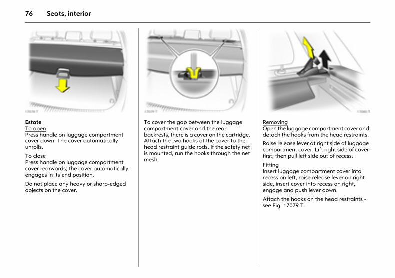
76 Seats, interior
Picture no: 17078t.tifEstate To open Press handle on luggage compartment cover down. The cover automatically unrolls.
To close Press handle on luggage compartment cover rearwards; the cover automatically engages in its end position.
Do not place any heavy or sharp-edged objects on the cover.
Picture no: 17079t.tifTo cover the gap between the luggage compartment cover and the rear backrests, there is a cover on the cartridge. Attach the two hooks of the cover to the head restraint guide rods. If the safety net is mounted, run the hooks through the net mesh.
Picture no: 17080t.tifRemoving Open the luggage compartment cover and detach the hooks from the head restraints.
Raise release lever at right side of luggage compartment cover. Lift right side of cover first, then pull left side out of recess.
Fitting Insert luggage compartment cover into recess on left, raise release lever on right side, insert cover into recess on right, engage and push lever down.
Attach the hooks on the head restraints - see Fig. 17079 T.
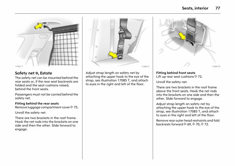
77Seats, interior
Picture no: 17081t.tifSafety net 3, Estate The safety net can be mounted behind the rear seats or, if the rear seat backrests are folded and the seat cushions raised, behind the front seats.
Passengers must not be carried behind the safety net.
Fitting behind the rear seatsRemove luggage compartment cover 3 75.
Unroll the safety net.
There are two brackets in the roof frame. Hook the net rods into the brackets on one side and then the other. Slide forward to engage.
Picture no: 17082t.tifAdjust strap length on safety net by attaching the upper hook to the eye of the strap, see illustration 17085 T, and attach to eyes in the right and left of the floor.
Picture no: 17083t.tifFitting behind front seats Lift up rear seat cushions 3 72.
Unroll the safety net.
There are two brackets in the roof frame above the front seats. Hook the net rods into the brackets on one side and then the other. Slide forward to engage.
Adjust strap length on safety net by attaching the upper hook to the eye of the strap, see illustration 17085 T, and attach to eyes in the right and left of the floor.
Remove rear outer head restraints and fold backrests forward 3 69, 3 70, 3 72.
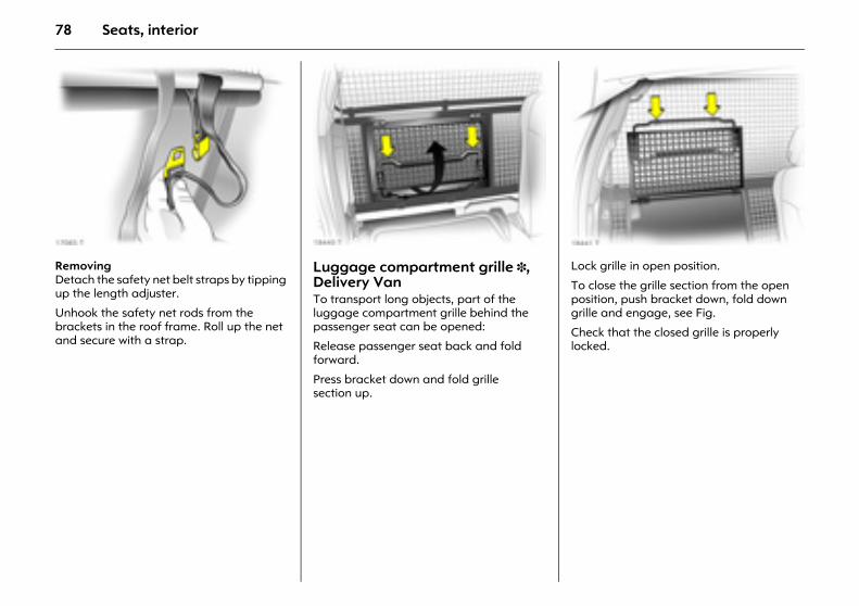
78 Seats, interior
Picture no: 17085t.tifRemoving Detach the safety net belt straps by tipping up the length adjuster.
Unhook the safety net rods from the brackets in the roof frame. Roll up the net and secure with a strap.
Picture no: 18440t.tifLuggage compartment grille 3, Delivery Van To transport long objects, part of the luggage compartment grille behind the passenger seat can be opened:
Release passenger seat back and fold forward.
Press bracket down and fold grille section up.
Picture no: 18441t.tifLock grille in open position.
To close the grille section from the open position, push bracket down, fold down grille and engage, see Fig.
Check that the closed grille is properly locked.
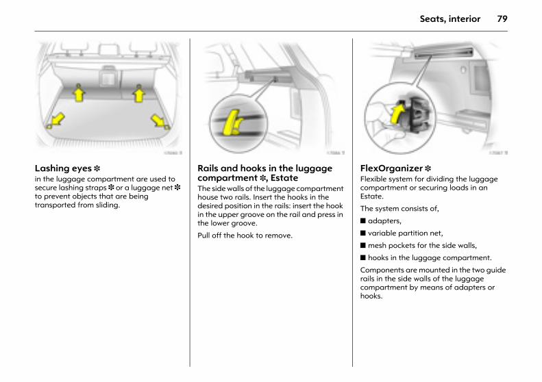
79Seats, interior
Picture no: 17090t.tifLashing eyes 3 in the luggage compartment are used to secure lashing straps 3 or a luggage net 3 to prevent objects that are being transported from sliding.
Picture no: 17086t.tifRails and hooks in the luggage compartment 3, EstateThe side walls of the luggage compartment house two rails. Insert the hooks in the desired position in the rails: insert the hook in the upper groove on the rail and press in the lower groove.
Pull off the hook to remove.
Picture no: 17087t.tifFlexOrganizer 3 Flexible system for dividing the luggage compartment or securing loads in an Estate.
The system consists of,
z adapters,
z variable partition net,
z mesh pockets for the side walls,
z hooks in the luggage compartment.
Components are mounted in the two guide rails in the side walls of the luggage compartment by means of adapters or hooks.
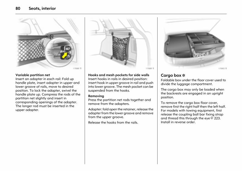
80 Seats, interior
Picture no: 17088t.tifVariable partition net Insert an adapter in each rail: Fold up handle plate, insert adapter in upper and lower groove of rails, move to desired position. To lock the adapter, swivel the handle plate up. Compress the rods of the partition net slightly and insert in corresponding openings of the adapter. The longer rod must be inserted in the upper adapter.
Picture no: 17089t.tifHooks and mesh pockets for side wallsInsert hooks in rails in desired position: insert hook in upper groove in rail and push into lower groove. The mesh pocket can be suspended from the hooks.
Removing Press the partition net rods together and remove from the adapters.
Adapter: fold open the retainer, release the adapter from the lower groove and remove from the upper groove.
Release the hooks from the rails.
Picture no: 17092t.tifCargo box 3 Foldable box under the floor cover used to divide the luggage compartment.
The cargo box may only be loaded when the backrests are engaged in an upright position.
To remove the cargo box floor cover, remove first the right half then the left half. For models with towing equipment, first release the coupling ball bar fixing strap and thread this through the eye 3 223. Install in reverse order.

81Seats, interior
Picture no: 18620t.tifLuggage compartment blind, Astra TwinTop To open Release luggage compartment blind from recesses on left and right, blind rolls up automatically.
To close Grasp the handle, pull the blind towards the rear of the vehicle and engage in the recess on the right and left.
Do not place any objects on the luggage compartment blind.
There must be no objects outside of or on top of the luggage compartment blind when the roof is open or in the process of opening.
The roof can only be operated with the luggage compartment blind engaged in the recess.
Picture no: 17978t.tifEasy Load (Electronically operated loading aid for the luggage compartment of the Astra TwinTop) The loading aid makes it possible to comfortably load the luggage compartment when the roof is open. The press of a button will raise the roof folded up in the luggage compartment 25 cm. This enlarges the load opening of the luggage compartment.
z Open the boot lid.
z Unhook luggage compartment blind and attach to rear window frame with holder, see Fig.
Picture no: 18621t.tifz Briefly press loading aid button: The
folded roof is raised. The roof remains in this end position for approx. 9 minutes.
6
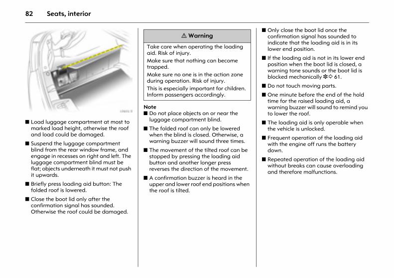
82 Seats, interior
Picture no: 17973t.tifz Load luggage compartment at most to
marked load height, otherwise the roof and load could be damaged.
z Suspend the luggage compartment blind from the rear window frame, and engage in recesses on right and left. The luggage compartment blind must be flat; objects underneath it must not push it upwards.
z Briefly press loading aid button: The folded roof is lowered.
z Close the boot lid only after the confirmation signal has sounded. Otherwise the roof could be damaged.
Notez Do not place objects on or near the
luggage compartment blind.
z The folded roof can only be lowered when the blind is closed. Otherwise, a warning buzzer will sound three times.
z The movement of the tilted roof can be stopped by pressing the loading aid button and another longer press reverses the direction of the movement.
z A confirmation buzzer is heard in the upper and lower roof end positions when the roof is tilted.
z Only close the boot lid once the confirmation signal has sounded to indicate that the loading aid is in its lower end position.
z If the loading aid is not in its lower end position when the boot lid is closed, a warning tone sounds or the boot lid is blocked mechanically 3 3 61.
z Do not touch moving parts.
z One minute before the end of the hold time for the raised loading aid, a warning buzzer will sound to remind you to lower the roof.
z The loading aid is only operable when the vehicle is unlocked.
z Frequent operation of the loading aid with the engine off runs the battery down.
z Repeated operation of the loading aid without breaks can cause overloading and therefore malfunctions.
9 Warning
Take care when operating the loading aid. Risk of injury.Make sure that nothing can become trapped. Make sure no one is in the action zone during operation. Risk of injury. This is especially important for children. Inform passengers accordingly.
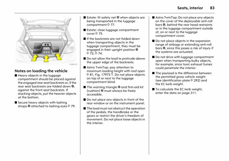
83Seats, interior
Picture no: 17093t.tifNotes on loading the vehicle z Heavy objects in the luggage
compartment should be placed against the engaged rear seat backrests or, if the rear seat backrests are folded down 3, against the front seat backrests. If stacking objects, put the heavier objects at the bottom.
z Secure heavy objects with lashing straps 3 attached to lashing eyes 3 79.
z Estate: fit safety net 3 when objects are being transported in the luggage compartment 3 77.
z Estate: close luggage compartment cover 3 75.
z If the backrests are not folded down when transporting objects in the luggage compartment, they must be engaged in their upright position 3 3 72, 3 74.
z Do not allow the load to protrude above the upper edge of the backrests.
z Astra TwinTop: pay attention to maximum loading height with roof open 3 81, Fig. 17973 T. Do not place objects on top of or next to the luggage compartment blind.
z The warning triangle 3 and first-aid kit (cushion) 3 must always be freely accessible.
z Do not place any objects in front of the rear window or on the instrument panel.
z The load must not obstruct the operation of the pedals, the handbrake or the gears or restrict the driver’s freedom of movement. Do not place loose objects in the interior.
z Astra TwinTop: Do not place any objects on the cover of the deployable anti-roll bars 3, behind the rear head restraints or in the luggage compartment outside of, on or next to the luggage compartment cover.
z Do not place objects in the expansion range of airbags or extending anti-roll bars 3, since this poses a risk of injury if the systems are actuated.
z Do not drive with luggage compartment open when transporting bulky objects, for example, since toxic exhaust fumes could penetrate the interior.
z The payload is the difference between the permitted gross vehicle weight (see identification plate 3 292) and the EC kerb weight.
z To calculate the EC kerb weight, enter the data on page 311.
84 Seats, interior
z The EC kerb weight includes weights for the driver (68 kg), luggage (7 kg) and all fluids (tank 90 % full).
z Optional equipment and accessories increase the kerb weight.
z Weights and payload 3 311.
z Driving with a roof load increases the sensitivity of the vehicle to cross-winds and has a detrimental effect on vehicle handling due to the vehicle’s higher centre of gravity. Distribute the load evenly and secure it properly with retaining straps. Adjust the tyre pressure to the load conditions. Do not drive faster than 120 km/h. Check and retighten the straps frequently. Observe country-specific regulations.
z The permissible roof load is 75 kg and 100 kg for caravan with roof railing. The roof load is the combined weight of the roof rack and the load.
Three-stage safety system Comprising:
z Three-point seat belts.
z Belt tensioners at the front seats.
z Airbag systems for driver, front seat passenger and rear outboard seats 3. On Astra TwinTop 3, roll-over bar behind rear seats.
The three stages are activated in sequence depending on the severity of the accident:
z The automatic seat belt locking devices prevent the belt strap from being pulled out and thus ensure that the vehicle occupants are retained in their seats.
z The front seat belts are pulled down at the belt buckles. This means the belts fit snugly, the occupants are decelerated early with the vehicle and the load on the body is reduced.
z In the event of a severe accident, the airbag systems and deployable anti-roll bars 3 also deploy, forming safety cushions for the occupants. The front airbags are inflated in two stages based on the severity of the collision.
Always observe the instructions supplied with the child restraint system..
9 Warning
The airbag systems serve to supplement the three-point seat belts and belt tensioners. The seat belts must therefore always be worn. Disregard of these instructions could lead to injuries or endanger life. Vehicle passengers should be informed accordingly.
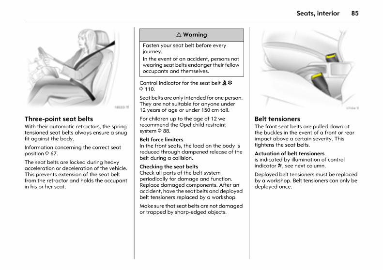
85Seats, interior
Picture no: 18533t.tifThree-point seat belts With their automatic retractors, the spring-tensioned seat belts always ensure a snug fit against the body.
Information concerning the correct seat position 3 67.
The seat belts are locked during heavy acceleration or deceleration of the vehicle. This prevents extension of the seat belt from the retractor and holds the occupant in his or her seat.
Control indicator for the seat belt X 3 3 110.
Seat belts are only intended for one person. They are not suitable for anyone under 12 years of age or under 150 cm tall.
For children up to the age of 12 we recommend the Opel child restraint system 3 88.
Belt force limiters In the front seats, the load on the body is reduced through dampened release of the belt during a collision.
Checking the seat belts Check all parts of the belt system periodically for damage and function. Replace damaged components. After an accident, have the seat belts and deployed belt tensioners replaced by a workshop.
Make sure that seat belts are not damaged or trapped by sharp-edged objects.
Picture no: 17104t.tifBelt tensioners The front seat belts are pulled down at the buckles in the event of a front or rear impact above a certain severity. This tightens the seat belts.
Actuation of belt tensioners is indicated by illumination of control indicator v, see next column.
Deployed belt tensioners must be replaced by a workshop. Belt tensioners can only be deployed once.
9 Warning
Fasten your seat belt before every journey. In the event of an accident, persons not wearing seat belts endanger their fellow occupants and themselves.
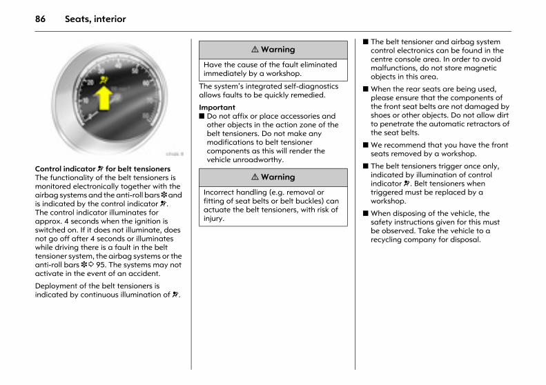
86 Seats, interior
Picture no: 17105t.tifControl indicator v for belt tensioners The functionality of the belt tensioners is monitored electronically together with the airbag systems and the anti-roll bars 3 and is indicated by the control indicator v. The control indicator illuminates for approx. 4 seconds when the ignition is switched on. If it does not illuminate, does not go off after 4 seconds or illuminates while driving there is a fault in the belt tensioner system, the airbag systems or the anti-roll bars 3 3 95. The systems may not activate in the event of an accident.
Deployment of the belt tensioners is indicated by continuous illumination of v.
The system’s integrated self-diagnostics allows faults to be quickly remedied.
Important z Do not affix or place accessories and
other objects in the action zone of the belt tensioners. Do not make any modifications to belt tensioner components as this will render the vehicle unroadworthy.
z The belt tensioner and airbag system control electronics can be found in the centre console area. In order to avoid malfunctions, do not store magnetic objects in this area.
z When the rear seats are being used, please ensure that the components of the front seat belts are not damaged by shoes or other objects. Do not allow dirt to penetrate the automatic retractors of the seat belts.
z We recommend that you have the front seats removed by a workshop.
z The belt tensioners trigger once only, indicated by illumination of control indicator v. Belt tensioners when triggered must be replaced by a workshop.
z When disposing of the vehicle, the safety instructions given for this must be observed. Take the vehicle to a recycling company for disposal.
9 Warning
Have the cause of the fault eliminated immediately by a workshop.
9 Warning
Incorrect handling (e.g. removal or fitting of seat belts or belt buckles) can actuate the belt tensioners, with risk of injury.
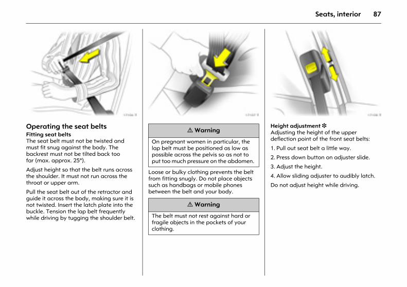
87Seats, interior
Picture no: 17106t.tifOperating the seat belts Fitting seat belts The seat belt must not be twisted and must fit snug against the body. The backrest must not be tilted back too far (max. approx. 25°).
Adjust height so that the belt runs across the shoulder. It must not run across the throat or upper arm.
Pull the seat belt out of the retractor and guide it across the body, making sure it is not twisted. Insert the latch plate into the buckle. Tension the lap belt frequently while driving by tugging the shoulder belt.
Picture no: 17107t.tif
Loose or bulky clothing prevents the belt from fitting snugly. Do not place objects such as handbags or mobile phones between the belt and your body.
Picture no: 17108t.tifHeight adjustment 3 Adjusting the height of the upper deflection point of the front seat belts:
1. Pull out seat belt a little way.
2. Press down button on adjuster slide.
3. Adjust the height.
4. Allow sliding adjuster to audibly latch.
Do not adjust height while driving.
9 Warning
On pregnant women in particular, the lap belt must be positioned as low as possible across the pelvis so as not to put too much pressure on the abdomen.
9 Warning
The belt must not rest against hard or fragile objects in the pockets of your clothing.
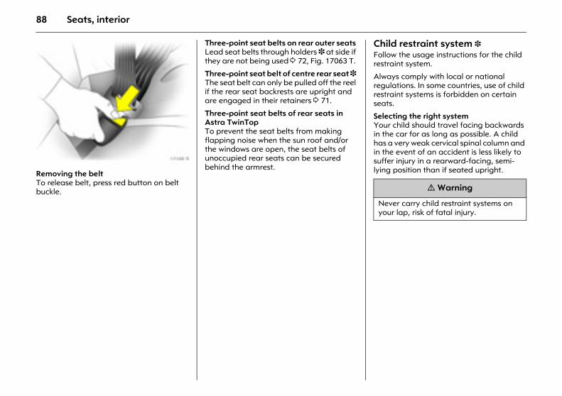
88 Seats, interior
Picture no: 17109t.tifRemoving the belt To release belt, press red button on belt buckle.
Three-point seat belts on rear outer seats Lead seat belts through holders 3 at side if they are not being used 3 72, Fig. 17063 T.
Three-point seat belt of centre rear seat 3 The seat belt can only be pulled off the reel if the rear seat backrests are upright and are engaged in their retainers 3 71.
Three-point seat belts of rear seats in Astra TwinTop To prevent the seat belts from making flapping noise when the sun roof and/or the windows are open, the seat belts of unoccupied rear seats can be secured behind the armrest.
Child restraint system 3 Follow the usage instructions for the child restraint system.
Always comply with local or national regulations. In some countries, use of child restraint systems is forbidden on certain seats.
Selecting the right system Your child should travel facing backwards in the car for as long as possible. A child has a very weak cervical spinal column and in the event of an accident is less likely to suffer injury in a rearward-facing, semi-lying position than if seated upright.
9 Warning
Never carry child restraint systems on your lap, risk of fatal injury.
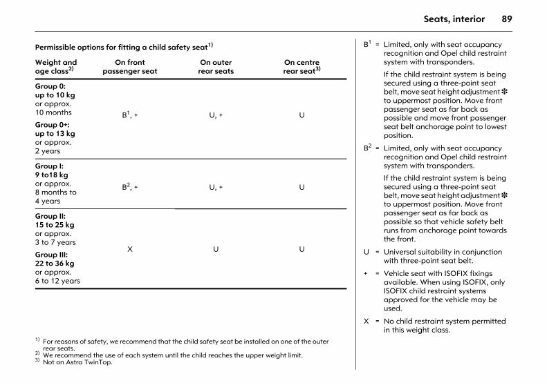
89Seats, interior
Permissible options for fitting a child safety seat1)
1) For reasons of safety, we recommend that the child safety seat be installed on one of the outer rear seats.
Weight and age class2)
2) We recommend the use of each system until the child reaches the upper weight limit.
On front passenger seat
On outer rear seats
On centre rear seat3)
3) Not on Astra TwinTop.
Group 0: up to 10 kg or approx. 10 months
Group 0+: up to 13 kg or approx. 2 years
B1, + U, + U
Group I: 9 to18 kg or approx. 8 months to 4 years
B2, + U, + U
Group II: 15 to 25 kg or approx. 3 to 7 years
Group III: 22 to 36 kg or approx. 6 to 12 years
X U U
B1 = Limited, only with seat occupancy recognition and Opel child restraint system with transponders.
If the child restraint system is being secured using a three-point seat belt, move seat height adjustment 3 to uppermost position. Move front passenger seat as far back as possible and move front passenger seat belt anchorage point to lowest position.
B2 = Limited, only with seat occupancy recognition and Opel child restraint system with transponders.
If the child restraint system is being secured using a three-point seat belt, move seat height adjustment 3 to uppermost position. Move front passenger seat as far back as possible so that vehicle safety belt runs from anchorage point towards the front.
U = Universal suitability in conjunction with three-point seat belt.
+ = Vehicle seat with ISOFIX fixings available. When using ISOFIX, only ISOFIX child restraint systems approved for the vehicle may be used.
X = No child restraint system permitted in this weight class.
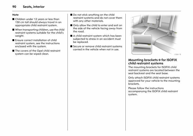
90 Seats, interior
Note
z Children under 12 years or less than 150 cm tall should always travel in an appropriate child restraint system.
z When transporting children, use the child restraint systems suitable for the child’s weight.
z Ensure correct installation of child restraint system, see the instructions enclosed with the system.
z The covers of the Opel child restraint system can be wiped clean.
z Do not stick anything on the child restraint systems and do not cover them with any other materials.
z Only allow the child to enter and exit on the side of the vehicle facing away from the road.
z A child restraint system which has been subjected to stress in an accident must be replaced.
z Secure or remove child restraint systems carried in the vehicle when not in use.
Picture no: 17091t.tifMounting brackets 3 for ISOFIX child restraint systems The mounting brackets for ISOFIX child restraint systems are located between the seat backrest and the seat base.
Only attach ISOFIX child restraint systems approved for your vehicle to the mounting brackets.
Please follow the instructions accompanying the ISOFIX child restraint system.
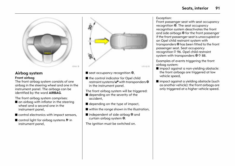
91Seats, interior
Picture no: 17111t.tifAirbag system Front airbag The front airbag system consists of one airbag in the steering wheel and one in the instrument panel. The airbags can be identified by the word AIRBAG.
The front airbag system comprises:z an airbag with inflator in the steering
wheel and a second one in the instrument panel,
z control electronics with impact sensors,
z control light for airbag systems v in instrument panel,
Picture no: 17112t.tifz seat occupancy recognition 3,
z the control indicator for Opel child restraint systems y with transponders 3 in the instrument panel.
The front airbag system will be triggered: z depending on the severity of the
accident,
z depending on the type of impact,
z within the range shown in the illustration,
z independent of side airbag 3 and curtain airbag system 3.
The ignition must be switched on.
Exception: Front passenger seat with seat occupancy recognition 3. The seat occupancy recognition system deactivates the front and side airbags 3 for the front passenger if the front passenger seat is unoccupied or an Opel child restraint system with transponders 3 has been fitted to the front passenger seat. Seat occupancy recognition 3 96. Opel child restraint system with transponders 3 3 88.
Examples of events triggering the front airbag system: z impact against a non-yielding obstacle:
the front airbags are triggered at low vehicle speed,
z impact against a yielding obstacle (such as another vehicle): the front airbags are only triggered at a higher vehicle speed.
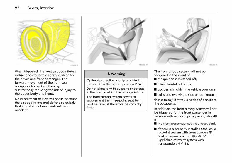
92 Seats, interior
Picture no: 17009t.tifWhen triggered, the front airbags inflate in milliseconds to form a safety cushion for the driver and front passenger. The forward movement of the front seat occupants is checked, thereby substantially reducing the risk of injury to the upper body and head.
No impairment of view will occur, because the airbags inflate and deflate so quickly that it is often not even noticed in an accident.
Picture no: 18532t.tif Picture no: 18533t.tifThe front airbag system will not be triggered in the event of z the ignition is switched off,
z minor frontal collisions,
z accidents in which the vehicle overturns,
z collisions involving a side or rear impact,
that is to say, if it would not be of benefit to the occupants.
In addition, the front airbag system will not be triggered for the front passenger in versions with seat occupancy recognition 3 if z the front passenger seat is unoccupied,
z if there is a properly installed Opel child restraint system with transponders 3. Seat occupancy recognition 3 96. Opel child restraint system with transponders 3 3 88.
9 Warning
Optimal protection is only provided if the seat is in the proper position 3 67. Do not place any body parts or objects in the area in which the airbags inflate. The front airbag system serves to supplement the three-point seat belt. Seat belts must therefore be correctly fitted.
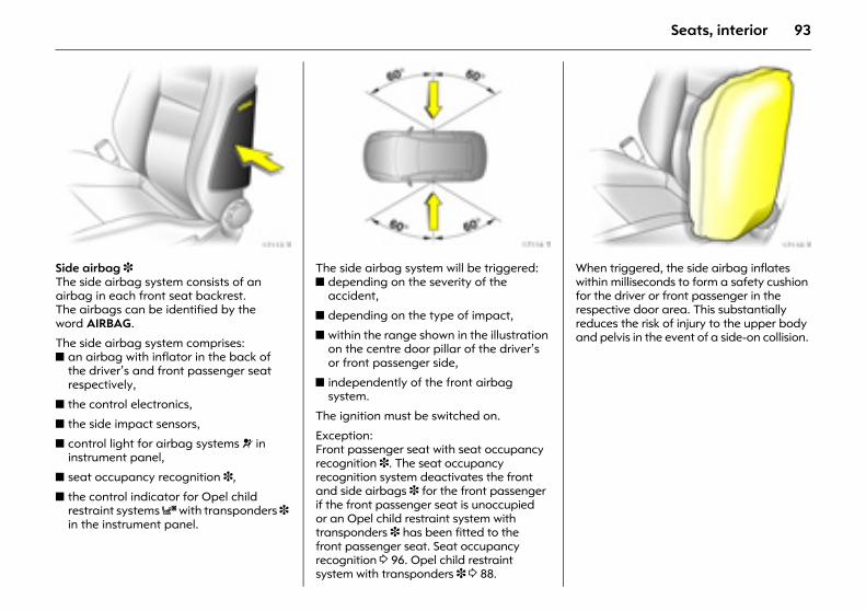
93Seats, interior
Picture no: 17113t.tifSide airbag 3 The side airbag system consists of an airbag in each front seat backrest. The airbags can be identified by the word AIRBAG.
The side airbag system comprises: z an airbag with inflator in the back of
the driver’s and front passenger seat respectively,
z the control electronics,
z the side impact sensors,
z control light for airbag systems v in instrument panel,
z seat occupancy recognition 3,
z the control indicator for Opel child restraint systems y with transponders 3 in the instrument panel.
Picture no: 17114t.tifThe side airbag system will be triggered:z depending on the severity of the
accident,
z depending on the type of impact,
z within the range shown in the illustration on the centre door pillar of the driver’s or front passenger side,
z independently of the front airbag system.
The ignition must be switched on.
Exception: Front passenger seat with seat occupancy recognition 3. The seat occupancy recognition system deactivates the front and side airbags 3 for the front passenger if the front passenger seat is unoccupied or an Opel child restraint system with transponders 3 has been fitted to the front passenger seat. Seat occupancy recognition 3 96. Opel child restraint system with transponders 3 3 88.
Picture no: 17110t.tifWhen triggered, the side airbag inflates within milliseconds to form a safety cushion for the driver or front passenger in the respective door area. This substantially reduces the risk of injury to the upper body and pelvis in the event of a side-on collision.
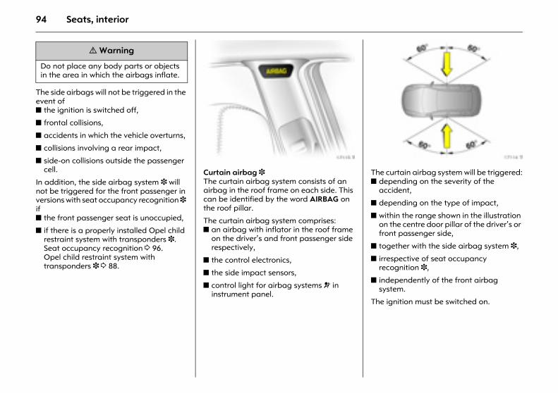
94 Seats, interior
The side airbags will not be triggered in the event of z the ignition is switched off,
z frontal collisions,
z accidents in which the vehicle overturns,
z collisions involving a rear impact,
z side-on collisions outside the passenger cell.
In addition, the side airbag system 3 will not be triggered for the front passenger in versions with seat occupancy recognition 3 if z the front passenger seat is unoccupied,
z if there is a properly installed Opel child restraint system with transponders 3. Seat occupancy recognition 3 96. Opel child restraint system with transponders 3 3 88.
Picture no: 17115t.tifCurtain airbag 3 The curtain airbag system consists of an airbag in the roof frame on each side. This can be identified by the word AIRBAG on the roof pillar.
The curtain airbag system comprises: z an airbag with inflator in the roof frame
on the driver’s and front passenger side respectively,
z the control electronics,
z the side impact sensors,
z control light for airbag systems v in instrument panel.
Picture no: 17114t.tifThe curtain airbag system will be triggered:z depending on the severity of the
accident,
z depending on the type of impact,
z within the range shown in the illustration on the centre door pillar of the driver’s or front passenger side,
z together with the side airbag system 3,
z irrespective of seat occupancy recognition 3,
z independently of the front airbag system.
The ignition must be switched on.
9 Warning
Do not place any body parts or objects in the area in which the airbags inflate.
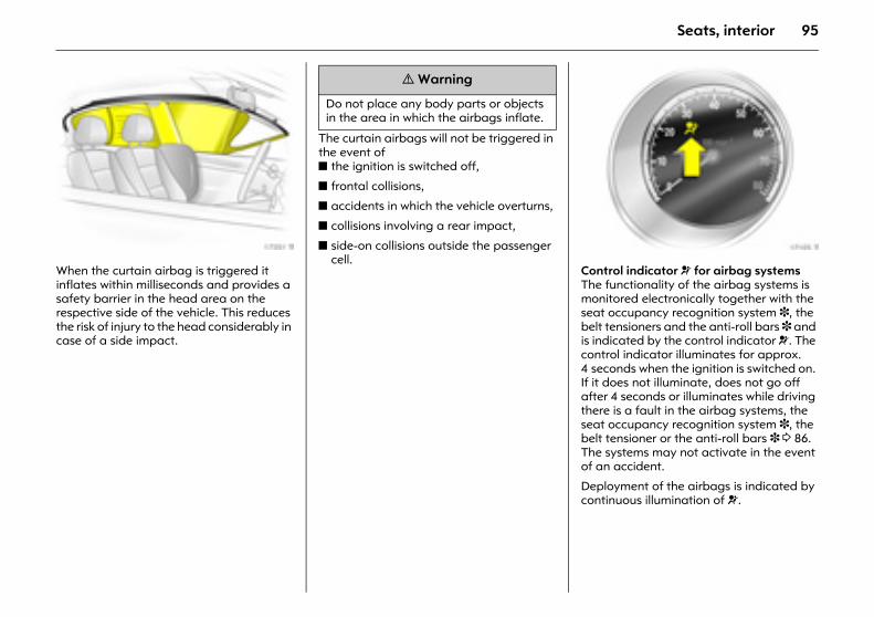
95Seats, interior
Picture no: 17351t.tifWhen the curtain airbag is triggered it inflates within milliseconds and provides a safety barrier in the head area on the respective side of the vehicle. This reduces the risk of injury to the head considerably in case of a side impact.
The curtain airbags will not be triggered in the event of z the ignition is switched off,
z frontal collisions,
z accidents in which the vehicle overturns,
z collisions involving a rear impact,
z side-on collisions outside the passenger cell. Picture no: 17105t.tif
Control indicator v for airbag systemsThe functionality of the airbag systems is monitored electronically together with the seat occupancy recognition system 3, the belt tensioners and the anti-roll bars 3 and is indicated by the control indicator v. The control indicator illuminates for approx. 4 seconds when the ignition is switched on. If it does not illuminate, does not go off after 4 seconds or illuminates while driving there is a fault in the airbag systems, the seat occupancy recognition system 3, the belt tensioner or the anti-roll bars 3 3 86. The systems may not activate in the event of an accident.
Deployment of the airbags is indicated by continuous illumination of v.
9 Warning
Do not place any body parts or objects in the area in which the airbags inflate.
96 Seats, interior
The system’s integrated self-diagnostics allows faults to be quickly remedied.
Seat occupancy recognition 3 The seat occupancy recognition system deactivates the front and side airbags 3 for the front passenger if the front passenger seat is not occupied or an Opel child restraint system with transponders 3 is fitted on the front passenger seat. The curtain airbag system 3 remains activated.
The control indicator y for seat occupancy recognition is located in the instrument panel. If the control indicator y illuminates for approx. 4 seconds when the ignition is switched on, the vehicle is equipped with seat occupancy recognition, see next page, Fig. 17117 T.
If an Opel child restraint system with transponders 3 is fitted, the control indicator y lights permanently after the ignition is switched on as soon as the system has detected the child restraint system. Only then may the child restraint system with transponders 3 be used on the passenger seat.
Picture no: 17116t.tifVehicles with seat occupancy recognition are also identified by a sticker on the lower panel of the front passenger seats, see illustration above.
Opel child restraint systems with transponders 3 are automatically detected if correctly fitted to the front passenger seat. When this type of child restraint system is in use on the front passenger seat, the front and side airbag systems for the front passenger seat are deactivated. The curtain airbag system remains activated. Pay attention to control indicator y for seat occupancy recognition 3 3 97.
9 Warning
Have the cause of the fault eliminated immediately by a workshop.
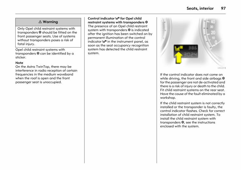
97Seats, interior
Opel child restraint systems with transponders 3 can be identified by a sticker.
Note On the Astra TwinTop, there may be interference in radio reception of certain frequencies in the medium waveband when the roof is open and the front passenger seat is unoccupied.
Control indicator y for Opel child restraint systems with transponders 3 The presence of an Opel child restraint system with transponders 3 is indicated after the ignition has been switched on by permanent illumination of the control indicator y in the instrument panel, as soon as the seat occupancy recognition system has detected the child restraint system.
Picture no: 17117t.tifIf the control indicator does not come on while driving, the front and side airbags 3 for the passenger are not de-activated and there is a risk of injury or death to the child. Fit child restraint systems on the rear seat. Have the cause of the fault eliminated by a workshop.
If the child restraint system is not correctly installed or the transponder is faulty, the control indicator flashes. Check for correct installation of child restraint system. To install the child restraint system with transponders 3, see the instructions enclosed with the system.
9 Warning
Only Opel child restraint systems with transponders 3 should be fitted on the front passenger seats. Use of systems without transponders poses a risk of fatal injury.
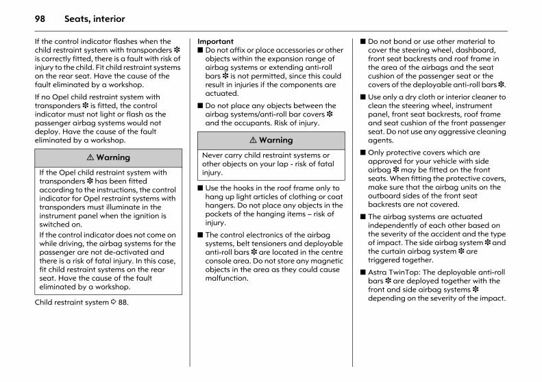
98 Seats, interior
If the control indicator flashes when the child restraint system with transponders 3 is correctly fitted, there is a fault with risk of injury to the child. Fit child restraint systems on the rear seat. Have the cause of the fault eliminated by a workshop.
If no Opel child restraint system with transponders 3 is fitted, the control indicator must not light or flash as the passenger airbag systems would not deploy. Have the cause of the fault eliminated by a workshop.
Child restraint system 3 88.
Important z Do not affix or place accessories or other
objects within the expansion range of airbag systems or extending anti-roll bars 3 is not permitted, since this could result in injuries if the components are actuated.
z Do not place any objects between the airbag systems/anti-roll bar covers 3 and the occupants. Risk of injury.
z Use the hooks in the roof frame only to hang up light articles of clothing or coat hangers. Do not place any objects in the pockets of the hanging items – risk of injury.
z The control electronics of the airbag systems, belt tensioners and deployable anti-roll bars 3 are located in the centre console area. Do not store any magnetic objects in the area as they could cause malfunction.
z Do not bond or use other material to cover the steering wheel, dashboard, front seat backrests and roof frame in the area of the airbags and the seat cushion of the passenger seat or the covers of the deployable anti-roll bars 3.
z Use only a dry cloth or interior cleaner to clean the steering wheel, instrument panel, front seat backrests, roof frame and seat cushion of the front passenger seat. Do not use any aggressive cleaning agents.
z Only protective covers which are approved for your vehicle with side airbag 3 may be fitted on the front seats. When fitting the protective covers, make sure that the airbag units on the outboard sides of the front seat backrests are not covered.
z The airbag systems are actuated independently of each other based on the severity of the accident and the type of impact. The side airbag system 3 and the curtain airbag system 3 are triggered together.
z Astra TwinTop: The deployable anti-roll bars 3 are deployed together with the front and side airbag systems 3 depending on the severity of the impact.
9 Warning
If the Opel child restraint system with transponders 3 has been fitted according to the instructions, the control indicator for Opel restraint systems with transponders must illuminate in the instrument panel when the ignition is switched on. If the control indicator does not come on while driving, the airbag systems for the passenger are not de-activated and there is a risk of fatal injury. In this case, fit child restraint systems on the rear seat. Have the cause of the fault eliminated by a workshop.
9 Warning
Never carry child restraint systems or other objects on your lap - risk of fatal injury.
99Seats, interior
z Each airbag or deployable roll-over bar 3 deploys once only. Have a workshop replace deployed airbags immediately.
z The speeds, directions of movement and deformation properties of the vehicles, and the properties of the obstacle concerned, determine the severity of the accident and triggering of the airbags. The degree of damage to your vehicle and the resulting repair costs alone are not indicative that the criteria for triggering of the airbags were met.
z Do not make any modifications to components of the airbag systems or the anti-roll bars 3 as this would render the vehicle unroadworthy.
z We recommend having the steering wheel, the instrument panel, all panelling parts, the door seals, the handles and the seats removed by a workshop.
z When disposing of the vehicle, the safety instructions given for this must be observed. Take the vehicle to a recycling company for disposal.
z Persons weighing less than 35 kg should only travel on the rear seats. This does not apply to children who are travelling in child restraint systems with transponders 3.
z In vehicles with seat occupancy recognition 3, do not place any heavy objects on the front passenger seat otherwise the airbag systems for the front passenger seat may be triggered in the event of an accident.
z In vehicles with seat occupancy recognition 3, to prevent malfunctions do not use protective covers or seat cushions on the front passenger seat.
z In order to prevent malfunctions when using an Opel child restraint system with transponders 3 on the front passenger seat, no objects (e.g. plastic sheet, stickers or heated mats) may be placed under the child restraint system.
9 Warning
The systems can be triggered abruptly and cause injury if they are handled improperly.
9 Warning
Child restraint systems as well as other objects must never be carried on the lap of passengers. If carried in this way, child restraint systems with transponders 3 in vehicles with seat occupancy recognition 3 could lead to front passenger airbag systems failing to trigger in the event of an accident.
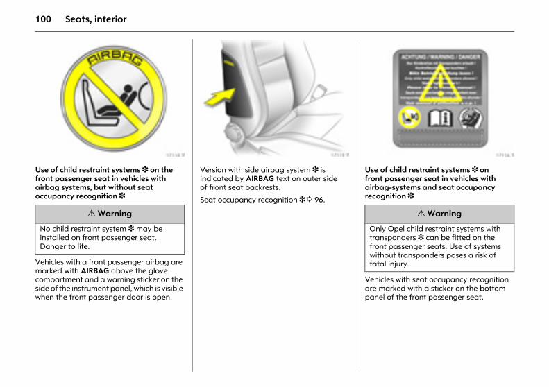
100 Seats, interior
Picture no: 17118t.tifUse of child restraint systems 3 on the front passenger seat in vehicles with airbag systems, but without seat occupancy recognition 3
Vehicles with a front passenger airbag are marked with AIRBAG above the glove compartment and a warning sticker on the side of the instrument panel, which is visible when the front passenger door is open.
Picture no: 17119t.tifVersion with side airbag system 3 is indicated by AIRBAG text on outer side of front seat backrests.
Seat occupancy recognition 3 3 96.
Picture no: 17116t.tifUse of child restraint systems 3 on front passenger seat in vehicles with airbag-systems and seat occupancy recognition 3
Vehicles with seat occupancy recognition are marked with a sticker on the bottom panel of the front passenger seat.
9 Warning
No child restraint system 3 may be installed on front passenger seat. Danger to life.
9 Warning
Only Opel child restraint systems with transponders 3 can be fitted on the front passenger seats. Use of systems without transponders poses a risk of fatal injury.
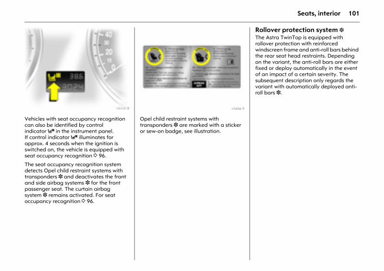
101Seats, interior
Picture no: 17117t.tifVehicles with seat occupancy recognition can also be identified by control indicator y in the instrument panel. If control indicator y illuminates for approx. 4 seconds when the ignition is switched on, the vehicle is equipped with seat occupancy recognition 3 96.
The seat occupancy recognition system detects Opel child restraint systems with transponders 3 and deactivates the front and side airbag systems 3 for the front passenger seat. The curtain airbag system 3 remains activated. For seat occupancy recognition 3 96.
Picture no: 17424t.tifOpel child restraint systems with transponders 3 are marked with a sticker or sew-on badge, see illustration.
Rollover protection system 3 The Astra TwinTop is equipped with rollover protection with reinforced windscreen frame and anti-roll bars behind the rear seat head restraints. Depending on the variant, the anti-roll bars are either fixed or deploy automatically in the event of an impact of a certain severity. The subsequent description only regards the variant with automatically deployed anti-roll bars 3.
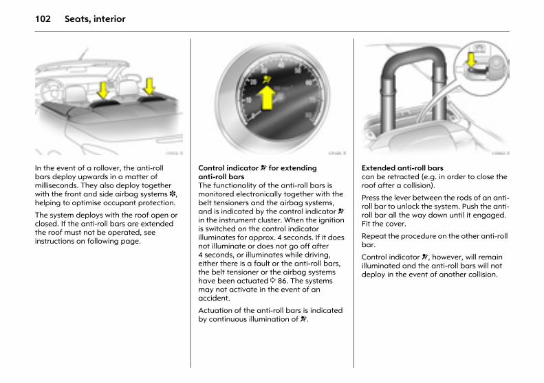
102 Seats, interior
Picture no: 17974t.tifIn the event of a rollover, the anti-roll bars deploy upwards in a matter of milliseconds. They also deploy together with the front and side airbag systems 3, helping to optimise occupant protection.
The system deploys with the roof open or closed. If the anti-roll bars are extended the roof must not be operated, see instructions on following page.
Picture no: 17105t.tifControl indicator v for extending anti-roll bars The functionality of the anti-roll bars is monitored electronically together with the belt tensioners and the airbag systems, and is indicated by the control indicator v in the instrument cluster. When the ignition is switched on the control indicator illuminates for approx. 4 seconds. If it does not illuminate or does not go off after 4 seconds, or illuminates while driving, either there is a fault or the anti-roll bars, the belt tensioner or the airbag systems have been actuated 3 86. The systems may not activate in the event of an accident.
Actuation of the anti-roll bars is indicated by continuous illumination of v.
Picture no: 17992t.tifExtended anti-roll bars can be retracted (e.g. in order to close the roof after a collision).
Press the lever between the rods of an anti-roll bar to unlock the system. Push the anti-roll bar all the way down until it engaged. Fit the cover.
Repeat the procedure on the other anti-roll bar.
Control indicator v, however, will remain illuminated and the anti-roll bars will not deploy in the event of another collision.
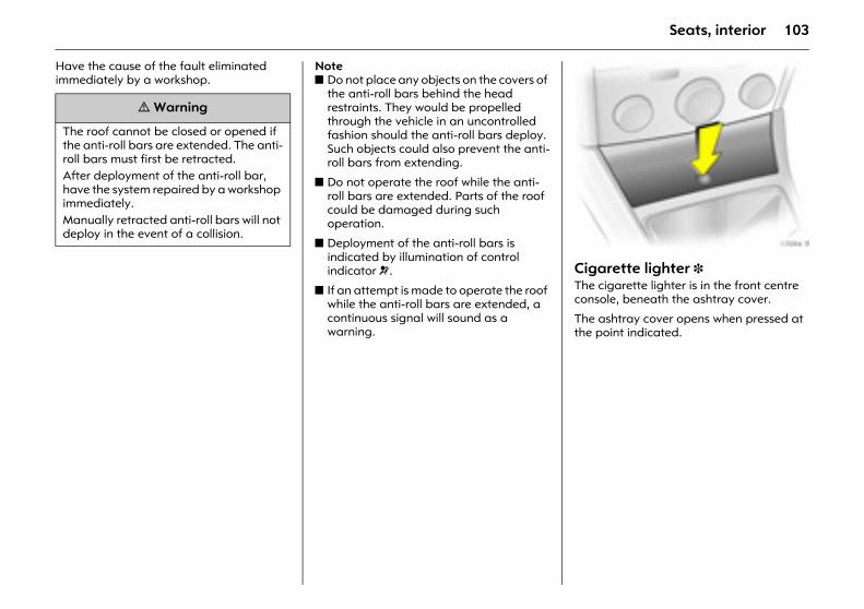
103Seats, interior
Have the cause of the fault eliminated immediately by a workshop.
Notez Do not place any objects on the covers of
the anti-roll bars behind the head restraints. They would be propelled through the vehicle in an uncontrolled fashion should the anti-roll bars deploy. Such objects could also prevent the anti-roll bars from extending.
z Do not operate the roof while the anti-roll bars are extended. Parts of the roof could be damaged during such operation.
z Deployment of the anti-roll bars is indicated by illumination of control indicator v.
z If an attempt is made to operate the roof while the anti-roll bars are extended, a continuous signal will sound as a warning.
Picture no: 17094t.tifCigarette lighter 3 The cigarette lighter is in the front centre console, beneath the ashtray cover.
The ashtray cover opens when pressed at the point indicated.
9 Warning
The roof cannot be closed or opened if the anti-roll bars are extended. The anti-roll bars must first be retracted. After deployment of the anti-roll bar, have the system repaired by a workshop immediately. Manually retracted anti-roll bars will not deploy in the event of a collision.
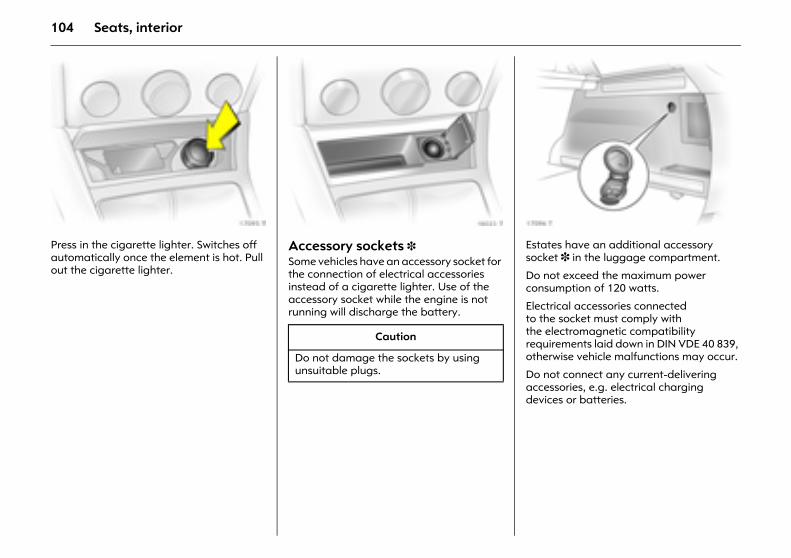
104 Seats, interior
Picture no: 17095t.tifPress in the cigarette lighter. Switches off automatically once the element is hot. Pull out the cigarette lighter.
Picture no: 18023t.tifAccessory sockets 3 Some vehicles have an accessory socket for the connection of electrical accessories instead of a cigarette lighter. Use of the accessory socket while the engine is not running will discharge the battery.
Picture no: 17096t.tifEstates have an additional accessory socket 3 in the luggage compartment.
Do not exceed the maximum power consumption of 120 watts.
Electrical accessories connected to the socket must comply with the electromagnetic compatibility requirements laid down in DIN VDE 40 839, otherwise vehicle malfunctions may occur.
Do not connect any current-delivering accessories, e.g. electrical charging devices or batteries.
Caution
Do not damage the sockets by using unsuitable plugs.
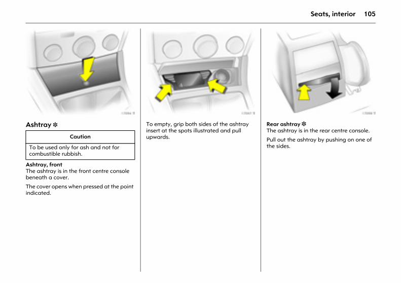
105Seats, interior
Picture no: 17094t.tifAshtray 3
Ashtray, front The ashtray is in the front centre console beneath a cover.
The cover opens when pressed at the point indicated.
Picture no: 17097t.tifTo empty, grip both sides of the ashtray insert at the spots illustrated and pull upwards.
Picture no: 17098t.tifRear ashtray 3 The ashtray is in the rear centre console.
Pull out the ashtray by pushing on one of the sides.
Caution
To be used only for ash and not for combustible rubbish.
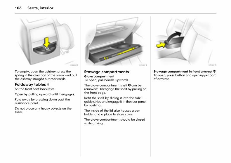
106 Seats, interior
Picture no: 17099t.tifTo empty, open the ashtray, press the spring in the direction of the arrow and pull the ashtray straight out rearwards.
Foldaway tables 3 on the front seat backrests.
Open by pulling upward until it engages.
Fold away by pressing down past the resistance point.
Do not place any heavy objects on the table.
Picture no: 17101t.tifStowage compartments Glove compartment To open, pull handle upwards.
The glove compartment shelf 3 can be removed: Disengage the shelf by pulling on the front edge.
Refit the shelf by sliding it into the side guide strips and engage it in the rear panel by pushing.
The inside of the lid also houses a pen holder and a place to store coins.
The glove compartment should be closed while driving.
Picture no: 17103t.tifStowage compartment in front armrest 3 To open, press button and open upper part of armrest.
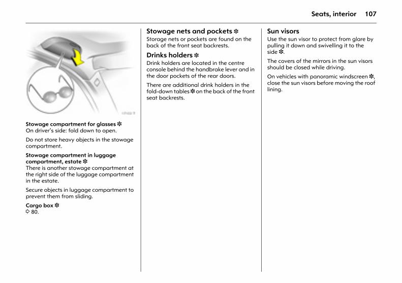
107Seats, interior
Picture no: 17102t.tifStowage compartment for glasses 3 On driver’s side: fold down to open.
Do not store heavy objects in the stowage compartment.
Stowage compartment in luggage compartment, estate 3 There is another stowage compartment at the right side of the luggage compartment in the estate.
Secure objects in luggage compartment to prevent them from sliding.
Cargo box 3 3 80.
Stowage nets and pockets 3 Storage nets or pockets are found on the back of the front seat backrests.
Drinks holders 3 Drink holders are located in the centre console behind the handbrake lever and in the door pockets of the rear doors.
There are additional drink holders in the fold-down tables 3 on the back of the front seat backrests.
Sun visorsUse the sun visor to protect from glare by pulling it down and swivelling it to the side 3.
The covers of the mirrors in the sun visors should be closed while driving.
On vehicles with panoramic windscreen 3, close the sun visors before moving the roof lining.
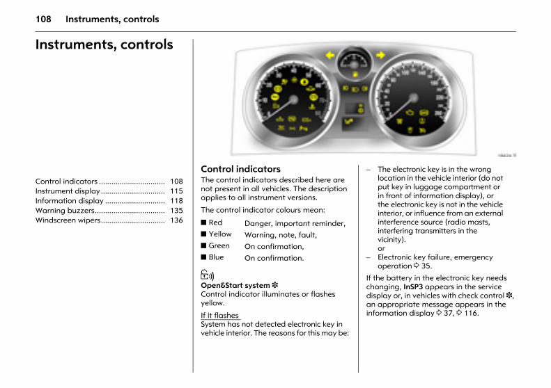
108 Instruments, controls
Instruments, controls
Control indicators ................................ 108 Instrument display............................... 115 Information display ............................. 118 Warning buzzers.................................. 135 Windscreen wipers............................... 136
Picture no: 18624t.tifControl indicators The control indicators described here are not present in all vehicles. The description applies to all instrument versions.
The control indicator colours mean:
0 Open&Start system 3 Control indicator illuminates or flashes yellow.
If it flashes System has not detected electronic key in vehicle interior. The reasons for this may be:
Picture no:
If the battery in the electronic key needs changing, InSP3 appears in the service display or, in vehicles with check control 3, an appropriate message appears in the information display 3 37, 3 116.
z Red Danger, important reminder,z Yellow Warning, note, fault,z Green On confirmation,z Blue On confirmation.
– The electronic key is in the wrong location in the vehicle interior (do not put key in luggage compartment or in front of information display), or the electronic key is not in the vehicle interior, or influence from an external interference source (radio masts, interfering transmitters in the vicinity). or
– Electronic key failure, emergency operation 3 35.
109Instruments, controls
Illuminated Fault in Open&Start system.
Lock or unlock vehicle using remote control or emergency key if necessary 3 41, or try using the spare key.
Emergency operation 3 35.
If 0 illuminates, this can also mean that the steering wheel lock is still locked: move steering wheel to and fro a little and press Start/Stop button again.
If 0 illuminates whilst driving a system error has occurred that may eventually lead to a complete failure.
If 0 illuminates or flashes: The Start/Stop button must be held depressed somewhat longer to switch off the ignition. It is possible that the vehicle will not start during the next start attempt.
If these flash continuously or if 0 lights, contact a workshop immediately.
I Engine oil pressure Control indicator illuminates red.
It illuminates when the ignition is switched on and goes out shortly after the engine starts.
Illuminates when the engine is running
1. Depress clutch.
2. Shift manual transmission or manual transmission automated 3 into neutral; for automatic transmission 3, set selector lever to N.
3. Move out of the flow of traffic as quickly as possible without impeding other vehicles.
4. Switch off ignition.
Contact a workshop for assistance. Caution
Engine lubrication may be interrupted. This may result in damage to the engine and/or locking of the drive wheels.
9 Warning
When the engine is off, considerably more force is needed to brake and steer. Do not remove key until vehicle has come to a standstill, otherwise the steering column lock could engage unexpectedly.

110 Instruments, controls
Picture no: 18624t.tifR Brake system, clutch system Control indicator illuminates or flashes red.
IlluminatedIt illuminates when the ignition is switched on if the hand brake is applied 3 210.
It illuminates upon release of the hand brake if the brake and clutch fluid level is too low 3 288.
Picture no: If it flashesOn vehicles with manual transmission automated 3, control indicator R flashes a few seconds after the ignition is switched off if the hand brake has not been applied.
9 Warning
Pull over. Stop your journey immediately. Contact a workshop.
v Airbag systems 3, belt tensioners 3, deployable anti-roll bars 3 Control indicator illuminates red.
Illuminates when the engine is runningFault in airbag system, belt tensioners or extending anti-roll bars 3 86, 3 95, 3 101
v Electronic Stability Programme (ESP®Plus) 3 Control indicator flashes or illuminates yellow.
Flashing during drivingSystem takes action 3 198, 3 199, 3 225.
Illuminates while drivingSystem deactivated or fault in system 3 199.
X Seat belt 3 Control indicator illuminates or flashes red.
Illuminated It illuminates when the ignition is switched on until the seat belt is fastened.
Flashing After starting off, the control indicator flashes if the safety belt is not fastened.
Fasten seat belt 3 87.
111Instruments, controls
Q Doors and luggage compartment openControl indicator illuminates red.
Comes on when a door or the luggage compartment is opened.
p Alternator Control indicator illuminates red.
It illuminates when the ignition is switched on and goes out shortly after the engine starts.
Illuminates when the engine is runningStop, switch off engine. Battery is not charging. Cooling may be faulty. For diesel engines, the effect of the brake servo may be lost. Contact a workshop immediately.
W Coolant temperature Control indicator illuminates red.
Illuminates when the engine is runningStop. Switch off the engine.
Check the coolant level immediately 3 287.
If the coolant level is not the problem, contact a workshop for assistance.
A Engine electronics, transmission electronics 3, immobiliser, diesel fuel filter 3 Control indicator illuminates or flashes yellow.
It illuminates for a few seconds when the ignition is switched on.
Illuminates when the engine is running Fault in engine or transmission electronics. Electronics have switched to emergency running programme, fuel consumption may be increased and the vehicle’s handling reduced 3 195. If the fault is not eliminated by restarting the vehicle, contact a workshop immediately.
Illuminated together with InSP4 in the service display: have the diesel fuel filter drained of water 3 3 287.
Flashes when the ignition is on Fault in the electronic immobiliser system; the engine cannot be started 3 29.
j Manual transmission automated 3, Engine start Control indicator illuminates yellow.
The engine can only be started if the foot brake is depressed. If the foot brake is not depressed, control indicator 3 176 illuminates.
IDS+Interactive Driving System 3, Continuous Damping Control (CDC) 3, SPORT mode 3 Control indicator illuminates yellow.
It illuminates for a few seconds when the ignition is switched on.
Illuminates while driving Fault in system. Contact a workshop immediately.
IDS+ 3 198, CDC 3 200, SPORT mode 3 200.
Caution
Coolant temperature is too high.
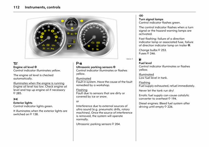
112 Instruments, controls
Picture no: 18624t.tifS Engine oil level 3 Control indicator illuminates yellow.
The engine oil level is checked automatically.
Illuminates when the engine is running Engine oil level too low. Check engine oil level and top up engine oil if necessary 3 285.
8 Exterior lights Control indicator lights green.
It illuminates when the exterior lights are switched on 3 138.
Picture no: r Ultrasonic parking sensors 3Control indicator illuminates or flashes yellow.
Illuminated Fault in system. Have the cause of the fault remedied by a workshop.
Flashing Fault due to sensors that are dirty or covered by ice or snow.
or
Interference due to external sources of ultra sound (e.g. pneumatic drills, rotary machines). Once the source of interference is removed, the system will operate normally.
Ultrasonic parking sensors 3 204.
O Turn signal lamps Control indicator flashes green.
The control indicator flashes when a turn signal or the hazard warning lamps are activated.
Fast flashing: failure of a direction indicator lamp or associated fuse, failure of direction indicator lamp on trailer 3.
Change bulbs 3 253. Fuses 3 246.
Y Fuel level Control indicator illuminates or flashes yellow.
Illuminated Low fuel level in tank.
Flashing Fuel supply exhausted, refuel immediately.
Never let the tank run dry!
Erratic fuel supply can cause catalytic converter to overheat 3 194.
Diesel engines: Bleed fuel system after driving until empty 3 226.
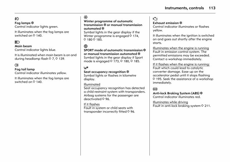
113Instruments, controls
> Fog lamps 3 Control indicator lights green.
It illuminates when the fog lamps are switched on 3 140.
C Main beam Control indicator lights blue.
It is illuminated when main beam is on and during headlamp flash 3 7, 3 139.
r Fog tail lamp Control indicator illuminates yellow.
It illuminates when the fog lamps are switched on 3 140.
T Winter programme of automatic transmission 3 or manual transmission automated 3 Symbol lights in the gear display if the Winter programme is engaged 3 174, 3 180 3 185.
1 SPORT mode of automatic transmission 3 or manual transmission automated 3 Symbol lights in the gear display if Sport mode is engaged 3 173, 3 180, 3 185.
y Seat occupancy recognition 3 Symbol lights or flashes in kilometre display.
Illuminated Seat occupancy recognition has detected a child restraint system with transponders. Airbag systems for the passenger are deactivated 3 96.
If it flashesFault in system or child seats with transponder incorrectly fitted 3 96.
Z Exhaust emission 3 Control indicator illuminates or flashes yellow.
It illuminates when the ignition is switched on and goes out shortly after the engine starts.
Illuminates when the engine is runningFault in emission control system. The permitted emissions may be exceeded. Contact a workshop immediately.
If it flashes when the engine is running:Fault which could lead to catalytic converter damage. Ease up on the accelerator pedal until it stops flashing 3 195. Seek the assistance of a workshop immediately.
u Anti-lock Braking System (ABS) 3 Control indicator illuminates red.
Illuminates while drivingFault in anti-lock braking system 3 211.
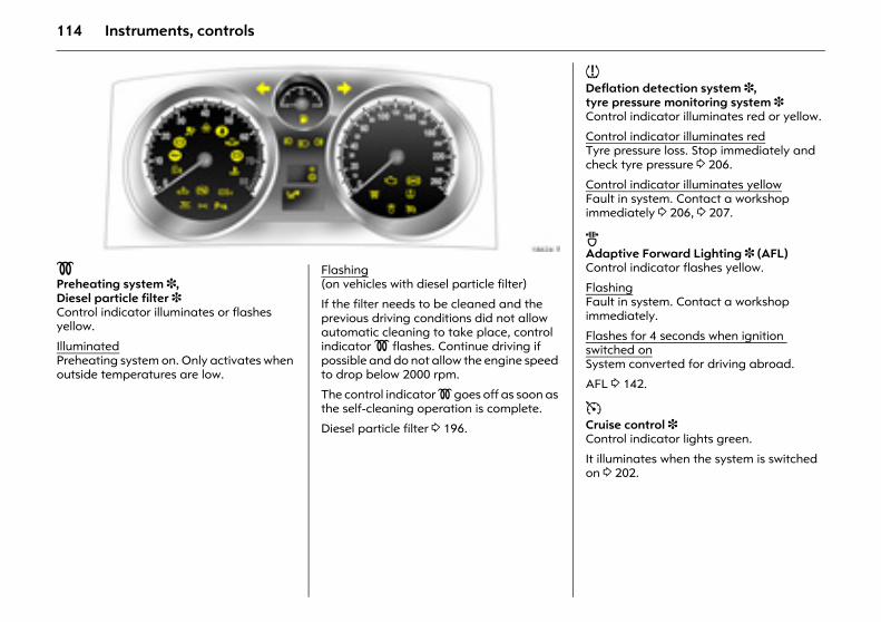
114 Instruments, controls
Picture no: 18624t.tif! Preheating system 3, Diesel particle filter 3 Control indicator illuminates or flashes yellow.
Illuminated Preheating system on. Only activates when outside temperatures are low.
Picture no: Flashing (on vehicles with diesel particle filter)
If the filter needs to be cleaned and the previous driving conditions did not allow automatic cleaning to take place, control indicator ! flashes. Continue driving if possible and do not allow the engine speed to drop below 2000 rpm.
The control indicator ! goes off as soon as the self-cleaning operation is complete.
Diesel particle filter 3 196.
w Deflation detection system 3, tyre pressure monitoring system 3 Control indicator illuminates red or yellow.
Control indicator illuminates redTyre pressure loss. Stop immediately and check tyre pressure 3 206.
Control indicator illuminates yellowFault in system. Contact a workshop immediately 3 206, 3 207.
B Adaptive Forward Lighting 3 (AFL) Control indicator flashes yellow.
Flashing Fault in system. Contact a workshop immediately.
Flashes for 4 seconds when ignition switched on System converted for driving abroad.
AFL 3 142.
m Cruise control 3 Control indicator lights green.
It illuminates when the system is switched on 3 202.
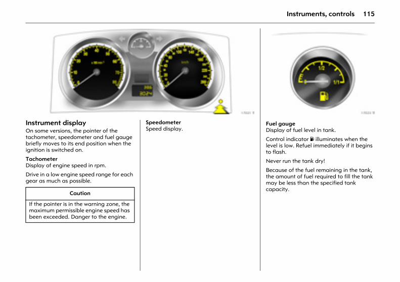
115Instruments, controls
Picture no: 17021t.tifInstrument display On some versions, the pointer of the tachometer, speedometer and fuel gauge briefly moves to its end position when the ignition is switched on.
Tachometer Display of engine speed in rpm.
Drive in a low engine speed range for each gear as much as possible.
Picture no: Speedometer Speed display.
Caution
If the pointer is in the warning zone, the maximum permissible engine speed has been exceeded. Danger to the engine.
Picture no: 17023t.tifFuel gauge
Display of fuel level in tank.
Control indicator Y illuminates when the level is low. Refuel immediately if it begins to flash.
Never run the tank dry!
Because of the fuel remaining in the tank, the amount of fuel required to fill the tank may be less than the specified tank capacity.
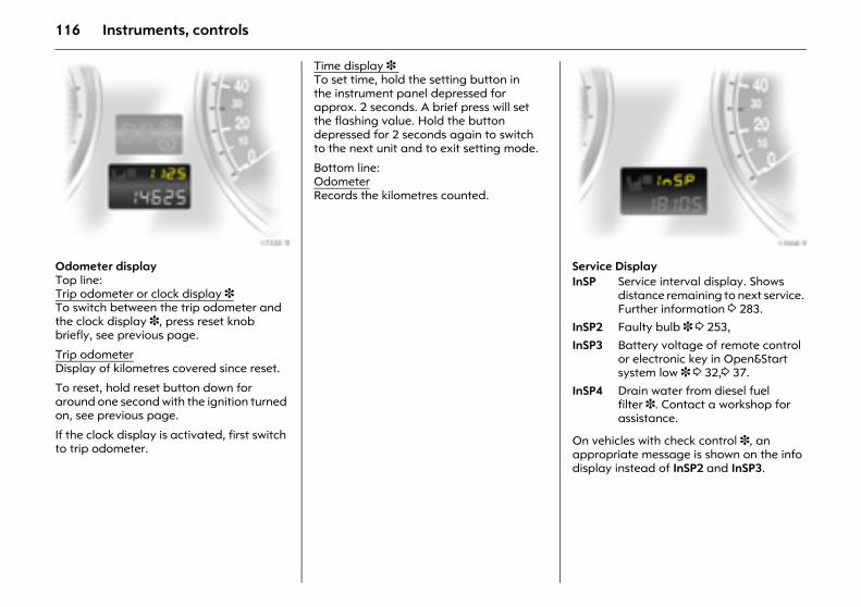
116 Instruments, controls
Picture no: 17335t.tif.Odometer displayTop line: Trip odometer or clock display 3 To switch between the trip odometer and the clock display 3, press reset knob briefly, see previous page.
Trip odometerDisplay of kilometres covered since reset.
To reset, hold reset button down for around one second with the ignition turned on, see previous page.
If the clock display is activated, first switch to trip odometer.
Time display 3 To set time, hold the setting button in the instrument panel depressed for approx. 2 seconds. A brief press will set the flashing value. Hold the button depressed for 2 seconds again to switch to the next unit and to exit setting mode.
Bottom line: OdometerRecords the kilometres counted.
Picture no: 17008t.tifService Display
On vehicles with check control 3, an appropriate message is shown on the info display instead of InSP2 and InSP3.
InSP Service interval display. Shows distance remaining to next service. Further information 3 283.
InSP2 Faulty bulb 3 3 253,
InSP3 Battery voltage of remote control or electronic key in Open&Start system low 3 3 32,3 37.
InSP4 Drain water from diesel fuel filter 3. Contact a workshop for assistance.
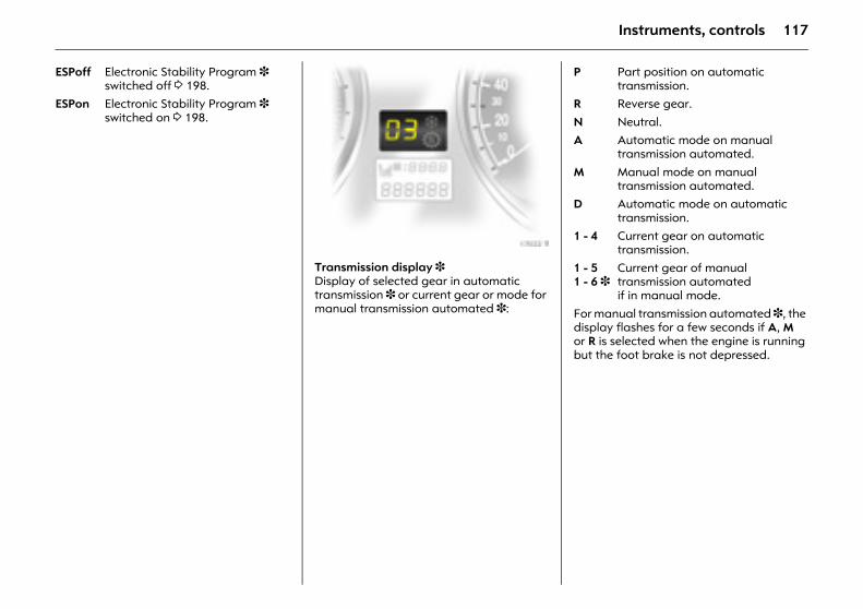
117Instruments, controls
Picture no: 17022t.tifTransmission display 3Display of selected gear in automatic transmission 3 or current gear or mode for manual transmission automated 3: For manual transmission automated 3, the
display flashes for a few seconds if A, M or R is selected when the engine is running but the foot brake is not depressed.
ESPoff Electronic Stability Program 3 switched off 3 198.
ESPon Electronic Stability Program 3 switched on 3 198.
P Part position on automatic transmission.
R Reverse gear.
N Neutral.A Automatic mode on manual
transmission automated.
M Manual mode on manual transmission automated.
D Automatic mode on automatic transmission.
1 - 4 Current gear on automatic transmission.
1 - 5 1 - 6 3
Current gear of manual transmission automated if in manual mode.
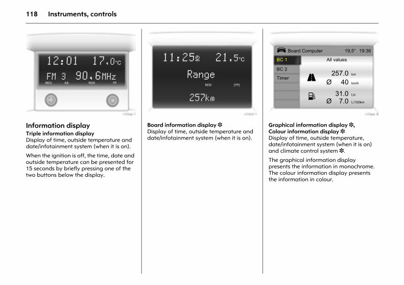
118 Instruments, controls
Picture no: 17336t.tifInformation display Triple information display Display of time, outside temperature and date/infotainment system (when it is on).
When the ignition is off, the time, date and outside temperature can be presented for 15 seconds by briefly pressing one of the two buttons below the display.
Picture no: 17337t.tifBoard information display 3Display of time, outside temperature and date/infotainment system (when it is on).
Picture no: 17344t.tifGraphical information display 3, Colour information display 3 Display of time, outside temperature, date/infotainment system (when it is on) and climate control system 3.
The graphical information display presents the information in monochrome. The colour information display presents the information in colour.
12:01 17,0°C
FM 3 90,6MHzREG AS RDS TP
11:25} 21.5°C
RangeRDS [TP]
257km
Ü Board Computer 19,5° 19:36
BC 1 All values
BC 2257.0 km
TimerØ 40 km/h
31.0 Ltr.
Ø 7.0 L/100km
1
8
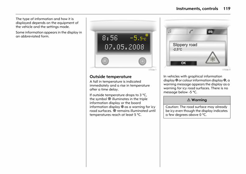
119Instruments, controls
The type of information and how it is displayed depends on the equipment of the vehicle and the settings made.
Some information appears in the display in an abbreviated form.
Picture no: 17336t.tifOutside temperature A fall in temperature is indicated immediately and a rise in temperature after a time delay.
If outside temperature drops to 3 °C, the symbol : illuminates in the triple information display or the board information display 3 as a warning for icy road surfaces. : remains illuminated until temperatures reach at least 5 °C.
Picture no: 17338t.tifIn vehicles with graphical information display 3 or colour information display 3, a warning message appears the display as a warning for icy road surfaces. There is no message below -5 °C.
8:56 -5,5°C
07.05.2008
:
9 Warning
Caution: The road surface may already be icy even though the display indicates a few degrees above 0 °C.
Slippery road-2,5°C
OK
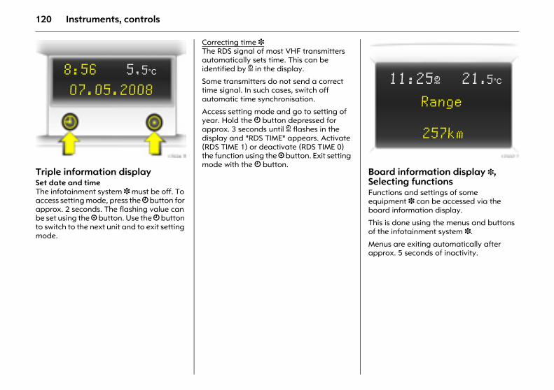
120 Instruments, controls
Picture no: 17024t.tifTriple information display Set date and timeThe infotainment system 3 must be off. To access setting mode, press the Ö button for approx. 2 seconds. The flashing value can be set using the ; button. Use the Ö button to switch to the next unit and to exit setting mode.
Correcting time 3 The RDS signal of most VHF transmitters automatically sets time. This can be identified by } in the display.
Some transmitters do not send a correct time signal. In such cases, switch off automatic time synchronisation.
Access setting mode and go to setting of year. Hold the Ö button depressed for approx. 3 seconds until } flashes in the display and "RDS TIME" appears. Activate (RDS TIME 1) or deactivate (RDS TIME 0) the function using the ; button. Exit setting mode with the Ö button. Picture no: 17337t.tif
Board information display 3, Selecting functionsFunctions and settings of some equipment 3 can be accessed via the board information display.
This is done using the menus and buttons of the infotainment system 3.
Menus are exiting automatically after approx. 5 seconds of inactivity.
8:56 5,5°C
07.05.200811:25} 21.5°C
Range
257km
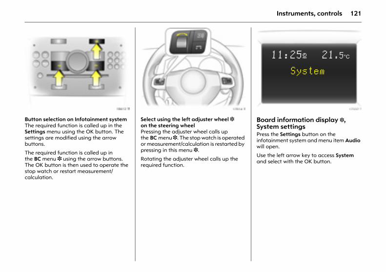
121Instruments, controls
Picture no: 18612t.tifButton selection on Infotainment system The required function is called up in the Settings menu using the OK button. The settings are modified using the arrow buttons.
The required function is called up in the BC menu 3 using the arrow buttons. The OK button is then used to operate the stop watch or restart measurement/calculation.
Picture no: 17014t.tifSelect using the left adjuster wheel 3 on the steering wheel Pressing the adjuster wheel calls up the BC menu 3. The stop watch is operated or measurement/calculation is restarted by pressing in this menu 3.
Rotating the adjuster wheel calls up the required function.
Picture no: 17337t.tifBoard information display 3, System settingsPress the Settings button on the infotainment system and menu item Audio will open.
Use the left arrow key to access System and select with the OK button.
11:25} 21.5°C
System
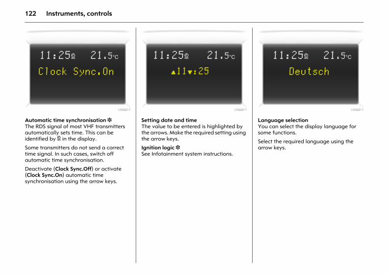
122 Instruments, controls
Picture no: 17337t.tifAutomatic time synchronisation 3 The RDS signal of most VHF transmitters automatically sets time. This can be identified by } in the display.
Some transmitters do not send a correct time signal. In such cases, switch off automatic time synchronisation.
Deactivate (Clock Sync.Off) or activate (Clock Sync.On) automatic time synchronisation using the arrow keys.
Picture no: 17337t.tifSetting date and time The value to be entered is highlighted by the arrows. Make the required setting using the arrow keys.
Ignition logic 3 See Infotainment system instructions.
Picture no: 17337t.tifLanguage selectionYou can select the display language for some functions.
Select the required language using the arrow keys.
11:25} 21.5°C
Clock Sync.On
11:25} 21.5°C
[11]:25
11:25} 21.5°C
Deutsch
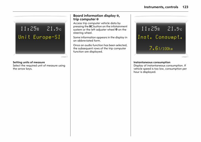
123Instruments, controls
Picture no: 17337t.tifSetting units of measureSelect the required unit of measure using the arrow keys.
Board information display 3, trip computer 3 Access trip computer vehicle data by pressing the BC button on the infotainment system or the left adjuster wheel 3 on the steering wheel.
Some information appears in the display in an abbreviated form.
Once an audio function has been selected, the subsequent rows of the trip computer function are displayed.
Picture no: 17337t.tifInstantaneous consumption Display of instantaneous consumption. If vehicle speed is too low, consumption per hour is displayed.
11:25} 21.5°C
Unit Europe-SI
11:25} 21.5°C
Inst. Consumpt.
7.6l/100km
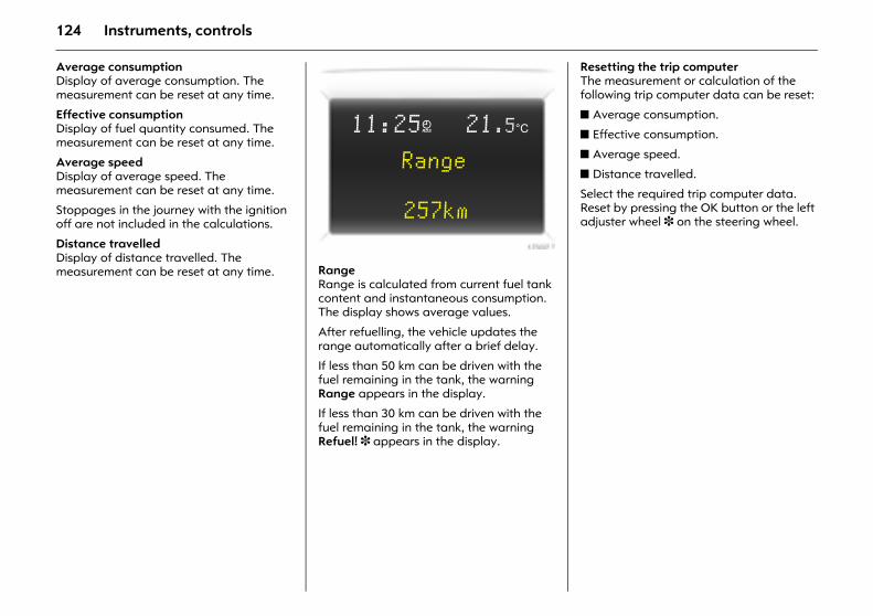
124 Instruments, controls
Average consumption Display of average consumption. The measurement can be reset at any time.
Effective consumption Display of fuel quantity consumed. The measurement can be reset at any time.
Average speed Display of average speed. The measurement can be reset at any time.
Stoppages in the journey with the ignition off are not included in the calculations.
Distance travelled Display of distance travelled. The measurement can be reset at any time.
Picture no: 17337t.tifRangeRange is calculated from current fuel tank content and instantaneous consumption. The display shows average values.
After refuelling, the vehicle updates the range automatically after a brief delay.
If less than 50 km can be driven with the fuel remaining in the tank, the warning Range appears in the display.
If less than 30 km can be driven with the fuel remaining in the tank, the warning Refuel! 3 appears in the display.
Resetting the trip computerThe measurement or calculation of the following trip computer data can be reset:
z Average consumption.
z Effective consumption.
z Average speed.
z Distance travelled.
Select the required trip computer data. Reset by pressing the OK button or the left adjuster wheel 3 on the steering wheel.
11:25} 21.5°C
Range
257km
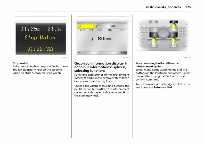
125Instruments, controls
Picture no: 17337t.tifStop watchSelect function, then press the OK button or the left adjuster wheel on the steering wheel to start or stop the stop watch.
Picture no: 17331t.tifGraphical information display 3 or colour information display 3, selecting functionsFunctions and settings of the infotainment system 3 and climate control system 3 can be accessed via the display.
This is done via the menus and buttons, the multifunction button 3 on the infotainment system or with the left adjuster wheel 3 on the steering wheel.
Picture no: 18612t.tifSelection using buttons 3 on the Infotainment system Select menu items using menus and the buttons on the Infotainment system. Select marked item using the OK button and confirm command.
To exit a menu, press the right or left arrow key to access Return or Main.
11:25} 21.5°C
Stop Watch
01:22:32h
FM AS [TP] REG CDin MP3
� 90.6 MHz
19,5° 19:36
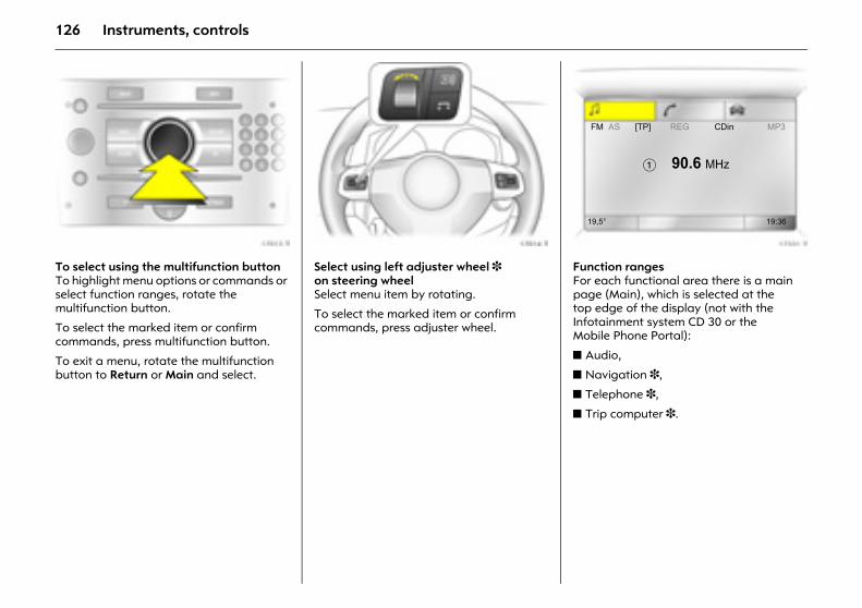
126 Instruments, controls
Picture no: 17013t.tifTo select using the multifunction buttonTo highlight menu options or commands or select function ranges, rotate the multifunction button.
To select the marked item or confirm commands, press multifunction button.
To exit a menu, rotate the multifunction button to Return or Main and select.
Picture no: 17014t.tifSelect using left adjuster wheel 3 on steering wheel Select menu item by rotating.
To select the marked item or confirm commands, press adjuster wheel.
Picture no: 17331t.tifFunction ranges For each functional area there is a main page (Main), which is selected at the top edge of the display (not with the Infotainment system CD 30 or the Mobile Phone Portal):
z Audio,
z Navigation 3,
z Telephone 3,
z Trip computer 3.
FM AS [TP] REG CDin MP3
� 90.6 MHz
19,5° 19:36
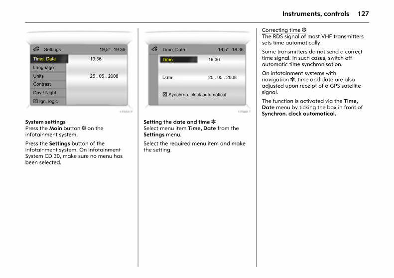
127Instruments, controls
Picture no: 17332t.tifSystem settings Press the Main button 3 on the infotainment system.
Press the Settings button of the infotainment system. On Infotainment System CD 30, make sure no menu has been selected.
Picture no: 17340t.tifSetting the date and time 3Select menu item Time, Date from the Settings menu.
Select the required menu item and make the setting.
Correcting time 3 The RDS signal of most VHF transmitters sets time automatically.
Some transmitters do not send a correct time signal. In such cases, switch off automatic time synchronisation.
On infotainment systems with navigation 3, time and date are also adjusted upon receipt of a GPS satellite signal.
The function is activated via the Time, Date menu by ticking the box in front of Synchron. clock automatical.
7 Settings 19,5° 19:36
Time, Date 19:36
Language
Units 25 . 05 . 2008
Contrast
Day / Night
Ign. logic
7 Time, Date 19,5° 19:36
Time 19:36
Date 25 . 05 . 2008
Synchron. clock automatical.
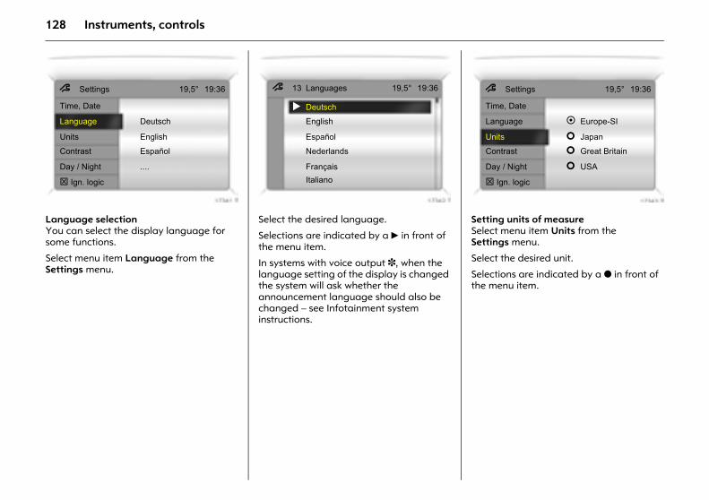
128 Instruments, controls
Picture no: 17341t.tifLanguage selectionYou can select the display language for some functions.
Select menu item Language from the Settings menu.
Picture no: 17342t.tifSelect the desired language.
Selections are indicated by a 6 in front of the menu item.
In systems with voice output 3, when the language setting of the display is changed the system will ask whether the announcement language should also be changed – see Infotainment system instructions.
Picture no: 17343t.tifSetting units of measureSelect menu item Units from the Settings menu.
Select the desired unit.
Selections are indicated by a o in front of the menu item.
7 Settings 19,5° 19:36
Time, Date
Language Deutsch
Units English
Contrast Español
Day / Night ....
Ign. logic
7 13 Languages 19,5° 19:36
Deutsch
English
Español
Nederlands
FrançaisItaliano
7 Settings 19,5° 19:36
Time, Date
Language Europe-SI
Units Japan
Contrast Great Britain
Day / Night USA
Ign. logic
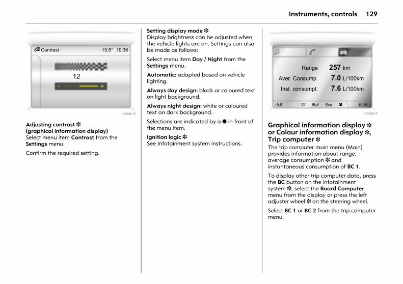
129Instruments, controls
Picture no: 17926t.tifAdjusting contrast 3(graphical information display) Select menu item Contrast from the Settings menu.
Confirm the required setting.
Setting display mode 3 Display brightness can be adjusted when the vehicle lights are on. Settings can also be made as follows:
Select menu item Day / Night from the Settings menu.
Automatic: adapted based on vehicle lighting.
Always day design: black or coloured text on light background.
Always night design: white or coloured text on dark background.
Selections are indicated by a o in front of the menu item.
Ignition logic 3 See Infotainment system instructions.
Picture no: 17329t.tifGraphical information display 3 or Colour information display 3, Trip computer 3 The trip computer main menu (Main) provides information about range, average consumption 3 and instantaneous consumption of BC 1.
To display other trip computer data, press the BC button on the infotainment system 3, select the Board Computer menu from the display or press the left adjuster wheel 3 on the steering wheel.
Select BC 1 or BC 2 from the trip computer menu.
7 Contrast 19,5° 19:36
12Range 257 km
Aver. Consump. 7.0 L/100km
Inst. consumpt. 7.6 L/100km
19,5° 23° 5 Eco x 19:36
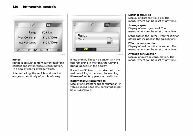
130 Instruments, controls
Picture no: 17329t.tifRangeRange is calculated from current fuel tank content and instantaneous consumption. The display shows average values.
After refuelling, the vehicle updates the range automatically after a brief delay.
Picture no: 17345t.tifIf less than 50 km can be driven with the fuel remaining in the tank, the warning Range appears in the display.
If less than 30 km can be driven with the fuel remaining in the tank, the warning Please refuel! 3 appears in the display.
Instantaneous consumption Display of instantaneous consumption. If vehicle speed is too low, consumption per hour is displayed.
Distance travelled Display of distance travelled. The measurement can be reset at any time.
Average speed Display of average speed. The measurement can be reset at any time.
Stoppages in the journey with the ignition off are not included in the calculations.
Effective consumption Display of fuel quantity consumed. The measurement can be reset at any time.
Average consumption Display of average consumption. The measurement can be reset at any time.
Range 257 km
Aver. Consump. 7.0 L/100km
Inst. consumpt. 7.6 L/100km
19,5° 23° 5 Eco x 19:36
Range33km
OK
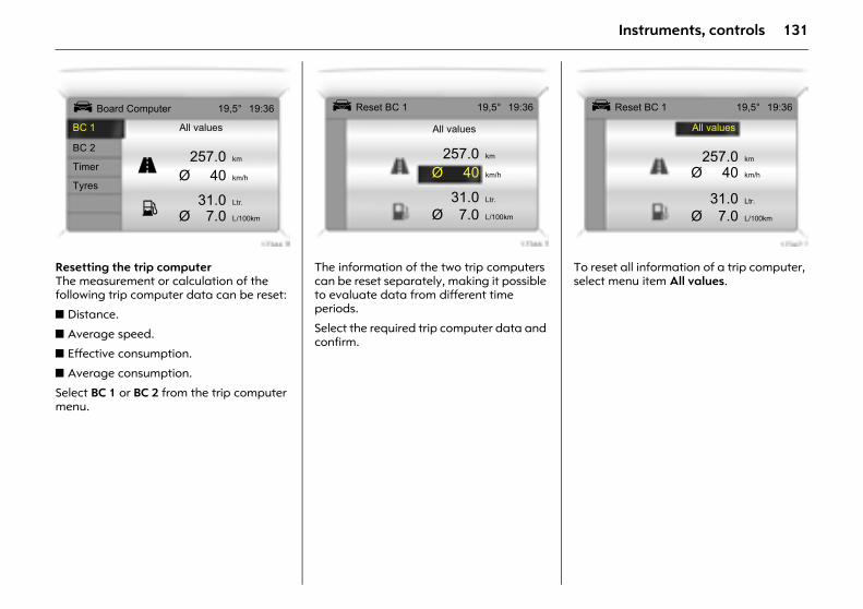
131Instruments, controls
Picture no: 17344t.tifResetting the trip computer The measurement or calculation of the following trip computer data can be reset:
z Distance.
z Average speed.
z Effective consumption.
z Average consumption.
Select BC 1 or BC 2 from the trip computer menu.
Picture no: 17346t.tifThe information of the two trip computers can be reset separately, making it possible to evaluate data from different time periods.
Select the required trip computer data and confirm.
Picture no: 17347t.tifTo reset all information of a trip computer, select menu item All values.
Ü Board Computer 19,5° 19:36
BC 1 All values
BC 2257.0 km
TimerØ 40 km/h
Tyres31.0 Ltr.
Ø 7.0 L/100km
1
8
Ü Reset BC 1 19,5° 19:36
All values
257.0 km
Ø 40 km/h
31.0 Ltr.
Ø 7.0 L/100km
Ü Reset BC 1 19,5° 19:36
All values
257.0 km
Ø 40 km/h
31.0 Ltr.
Ø 7.0 L/100km
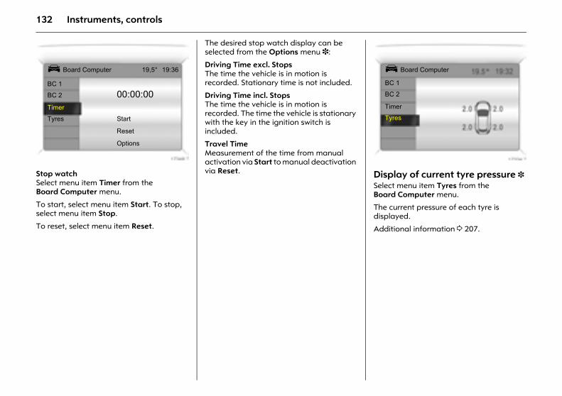
132 Instruments, controls
Picture no: 17348t.tifStop watchSelect menu item Timer from the Board Computer menu.
To start, select menu item Start. To stop, select menu item Stop.
To reset, select menu item Reset.
The desired stop watch display can be selected from the Options menu 3:
Driving Time excl. Stops The time the vehicle is in motion is recorded. Stationary time is not included.
Driving Time incl. Stops The time the vehicle is in motion is recorded. The time the vehicle is stationary with the key in the ignition switch is included.
Travel Time Measurement of the time from manual activation via Start to manual deactivation via Reset.
Picture no: 17334t.tifDisplay of current tyre pressure 3 Select menu item Tyres from the Board Computer menu.
The current pressure of each tyre is displayed.
Additional information 3 207.
Ü Board Computer 19,5° 19:36
BC 1
BC 2 00:00:00Timer
Tyres Start
Reset
Options
Ü Board Computer
BC 1
BC 2
Timer
Tyres
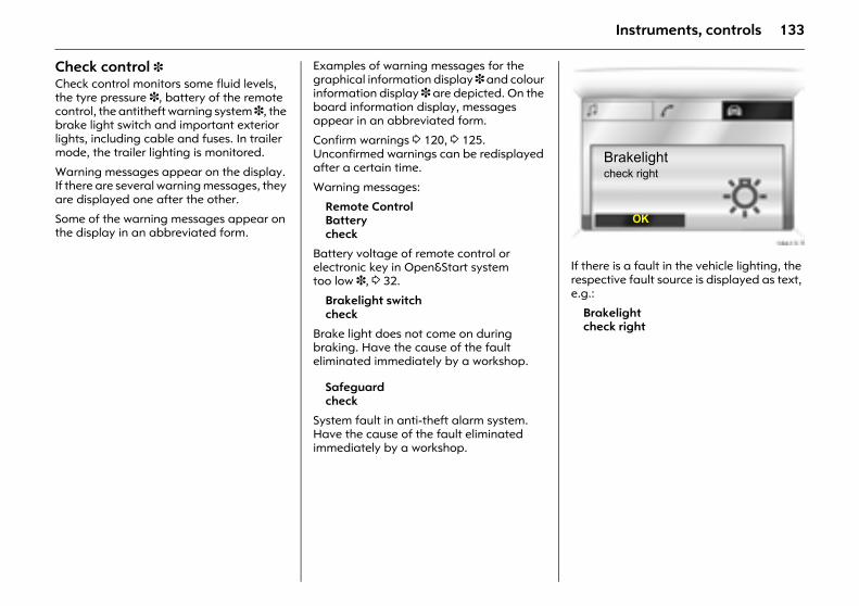
133Instruments, controls
Check control 3 Check control monitors some fluid levels, the tyre pressure 3, battery of the remote control, the antitheft warning system 3, the brake light switch and important exterior lights, including cable and fuses. In trailer mode, the trailer lighting is monitored.
Warning messages appear on the display. If there are several warning messages, they are displayed one after the other.
Some of the warning messages appear on the display in an abbreviated form.
Examples of warning messages for the graphical information display 3 and colour information display 3 are depicted. On the board information display, messages appear in an abbreviated form.
Confirm warnings 3 120, 3 125. Unconfirmed warnings can be redisplayed after a certain time.
Warning messages:
Remote ControlBatterycheck
Battery voltage of remote control or electronic key in Open&Start system too low 3, 3 32.
Brakelight switchcheck
Brake light does not come on during braking. Have the cause of the fault eliminated immediately by a workshop.
Safeguardcheck
System fault in anti-theft alarm system. Have the cause of the fault eliminated immediately by a workshop.
Picture no: 18613t.tifIf there is a fault in the vehicle lighting, the respective fault source is displayed as text, e.g.:
Brakelightcheck right
Brakelightcheck right
OK
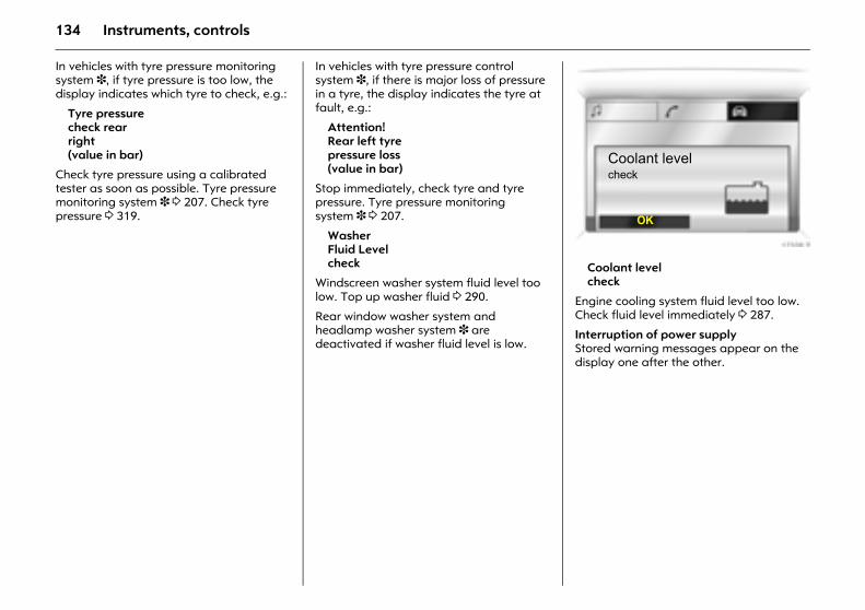
134 Instruments, controls
In vehicles with tyre pressure monitoring system 3, if tyre pressure is too low, the display indicates which tyre to check, e.g.:
Tyre pressurecheck rear right(value in bar)
Check tyre pressure using a calibrated tester as soon as possible. Tyre pressure monitoring system 3 3 207. Check tyre pressure 3 319.
In vehicles with tyre pressure control system 3, if there is major loss of pressure in a tyre, the display indicates the tyre at fault, e.g.:
Attention!Rear left tyre pressure loss (value in bar)
Stop immediately, check tyre and tyre pressure. Tyre pressure monitoring system 3 3 207.
Washer Fluid Levelcheck
Windscreen washer system fluid level too low. Top up washer fluid 3 290.
Rear window washer system and headlamp washer system 3 are deactivated if washer fluid level is low.
Picture no: 17339t.tifCoolant levelcheck
Engine cooling system fluid level too low. Check fluid level immediately 3 287.
Interruption of power supply Stored warning messages appear on the display one after the other.
Coolant levelcheck
OK
135Instruments, controls
Warning buzzersWhen starting the engine or whilst driving:z If the electronic key of the Open&Start
system 3 is not present or is not recognised.
z If seat belt 3 is not fastened.
z If a door or the tailgate is ajar when the vehicle starts off.
z Once you have reached a certain speed 3 if the hand brake is applied.
z When a factory-programmed speed is exceeded 3.
z With manual transmission automated 3, if the driver’s door is opened when the engine is running, a gear is engaged and the foot brake is not depressed.
When the vehicle is parked and the driver’s door is opened:z When the key is in the ignition switch 3.
z When the following are switched on: Parking lamps or dipped beam.
z With Open&Start system 3 and automatic transmission if the selector lever is not in P.
z With manual transmission automated 3, if the hand brake is not applied and no gear is engaged when the engine is off.
Indicator and warning buzzers for Astra TwinTop 3:z Indicator buzzer upon completed
opening or closing of the convertible hardtop.
z Indicator buzzer upon completed raising or lowering of the electric luggage compartment loading aid.
z Gong tone if the boot lid is not closed during roof operation.
z Gong tone if the boot lid is not fully opening during operation of the luggage compartment loading aid.
z Gong tone during roof operation if vehicle speed exceeds 30 km/h.
z Gong tone when vehicle speed exceeds 30 km/h if the roof is not fully open or closed.
z Three gong tones during roof or loading aid operation if the luggage compartment blind is not attached.
z Three gong tones during roof operation if outside temperature is below -20 °C, vehicle battery voltage is too low or the system is overloaded.
z Continuous warning buzzer during roof operation if the anti-roll bars 3 have been triggered.
z Continuous warning buzzer starting one minute before the end of the 9-minute standby time with the roof in an intermediate position.
z Continuous warning buzzer starting one minute before the end of the 9-minute standby time with the loading aid in a raised position.
z Persistent warning buzzer when closing the luggage compartment lid, if the lowering process of the electric load aid is not complete or has been interrupted.
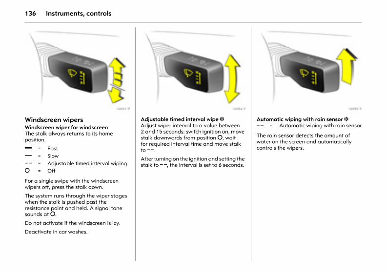
136 Instruments, controls
Picture no: 16993t.tifWindscreen wipers Windscreen wiper for windscreenThe stalk always returns to its home position.
For a single swipe with the windscreen wipers off, press the stalk down.
The system runs through the wiper stages when the stalk is pushed past the resistance point and held. A signal tone sounds at §.
Do not activate if the windscreen is icy.
Deactivate in car washes.
Picture no: 16994t.tifAdjustable timed interval wipe 3 Adjust wiper interval to a value between 2 and 15 seconds: switch ignition on, move stalk downwards from position §, wait for required interval time and move stalk to $.
After turning on the ignition and setting the stalk to $, the interval is set to 6 seconds.
Picture no: 16995t.tifAutomatic wiping with rain sensor 3
The rain sensor detects the amount of water on the screen and automatically controls the wipers. & = Fast
% = Slow $ = Adjustable timed interval wiping§ = Off
$ = Automatic wiping with rain sensor
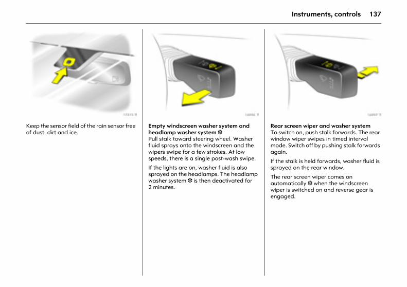
137Instruments, controls
Picture no: 17315t.tifKeep the sensor field of the rain sensor free of dust, dirt and ice.
Picture no: 16996t.tifEmpty windscreen washer system and headlamp washer system 3 Pull stalk toward steering wheel. Washer fluid sprays onto the windscreen and the wipers swipe for a few strokes. At low speeds, there is a single post-wash swipe.
If the lights are on, washer fluid is also sprayed on the headlamps. The headlamp washer system 3 is then deactivated for 2 minutes.
Picture no: 16997t.tifRear screen wiper and washer system To switch on, push stalk forwards. The rear window wiper swipes in timed interval mode. Switch off by pushing stalk forwards again.
If the stalk is held forwards, washer fluid is sprayed on the rear window.
The rear screen wiper comes on automatically 3 when the windscreen wiper is switched on and reverse gear is engaged.
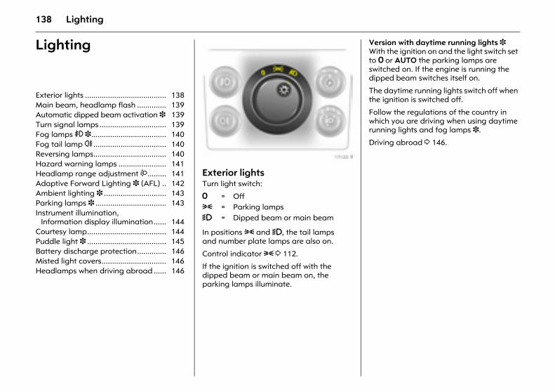
138 Lighting
Lighting
Picture no: 17122t.tifExterior lightsTurn light switch:
In positions 8 and 9, the tail lamps and number plate lamps are also on.
Control indicator 8 3 112.
If the ignition is switched off with the dipped beam or main beam on, the parking lamps illuminate.
Version with daytime running lights 3 With the ignition on and the light switch set to 7 or AUTO the parking lamps are switched on. If the engine is running the dipped beam switches itself on.
The daytime running lights switch off when the ignition is switched off.
Follow the regulations of the country in which you are driving when using daytime running lights and fog lamps 3.
Driving abroad 3 146.
Exterior lights ....................................... 138 Main beam, headlamp flash .............. 139 Automatic dipped beam activation 3 139 Turn signal lamps ................................ 139 Fog lamps > 3.................................... 140 Fog tail lamp r ................................... 140 Reversing lamps................................... 140 Hazard warning lamps ....................... 141 Headlamp range adjustment ?......... 141 Adaptive Forward Lighting 3 (AFL) .. 142 Ambient lighting 3 .............................. 143 Parking lamps 3 .................................. 143 Instrument illumination,
Information display illumination...... 144 Courtesy lamp...................................... 144 Puddle light 3 ...................................... 145 Battery discharge protection.............. 146 Misted light covers............................... 146 Headlamps when driving abroad ...... 146
7 = Off8 = Parking lamps9 = Dipped beam or main beam
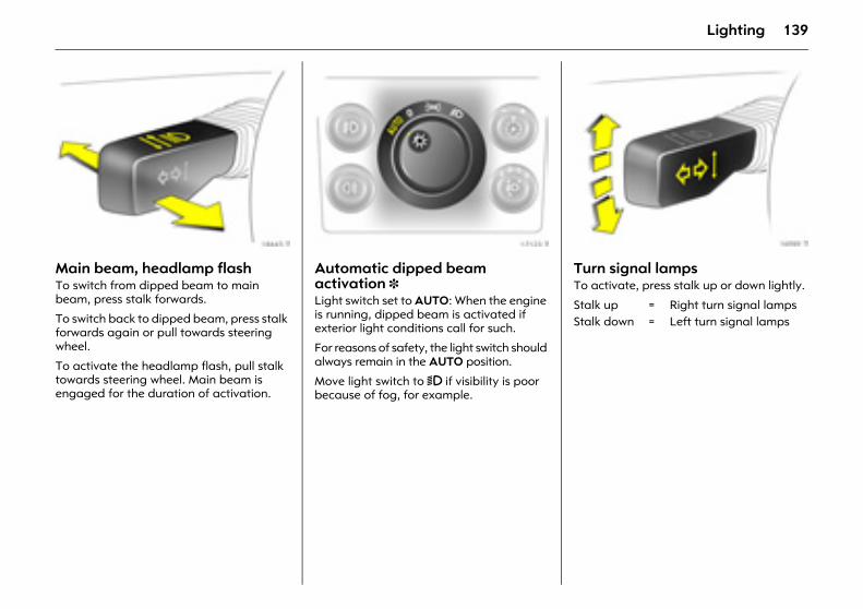
139Lighting
Picture no: 18445t.tifMain beam, headlamp flash To switch from dipped beam to main beam, press stalk forwards.
To switch back to dipped beam, press stalk forwards again or pull towards steering wheel.
To activate the headlamp flash, pull stalk towards steering wheel. Main beam is engaged for the duration of activation.
Picture no: 17123t.tifAutomatic dipped beam activation 3 Light switch set to AUTO: When the engine is running, dipped beam is activated if exterior light conditions call for such.
For reasons of safety, the light switch should always remain in the AUTO position.
Move light switch to 9 if visibility is poor because of fog, for example.
Picture no: 16989t.tifTurn signal lamps To activate, press stalk up or down lightly.
Stalk up = Right turn signal lampsStalk down = Left turn signal lamps
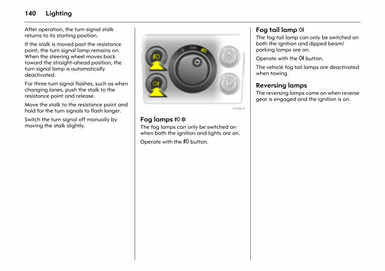
140 Lighting
After operation, the turn signal stalk returns to its starting position.
If the stalk is moved past the resistance point, the turn signal lamp remains on. When the steering wheel moves back toward the straight-ahead position, the turn signal lamp is automatically deactivated.
For three turn signal flashes, such as when changing lanes, push the stalk to the resistance point and release.
Move the stalk to the resistance point and hold for the turn signals to flash longer.
Switch the turn signal off manually by moving the stalk slightly.
Picture no: 17124t.tifFog lamps > 3 The fog lamps can only be switched on when both the ignition and lights are on.
Operate with the > button.
Fog tail lamp r The fog tail lamp can only be switched on both the ignition and dipped beam/parking lamps are on.
Operate with the r button.
The vehicle fog tail lamps are deactivated when towing.
Reversing lamps The reversing lamps come on when reverse gear is engaged and the ignition is on.
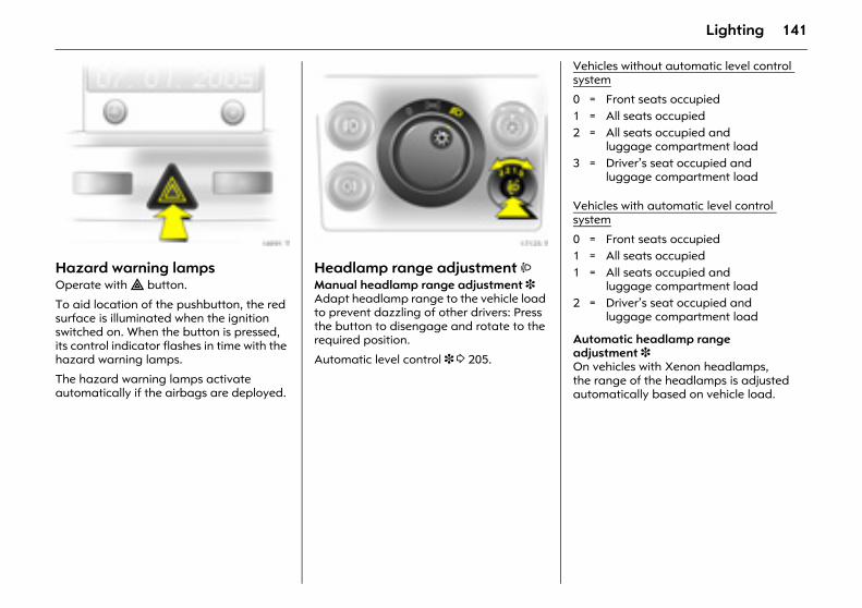
141Lighting
Picture no: 16991t.tifHazard warning lamps Operate with ¨ button.
To aid location of the pushbutton, the red surface is illuminated when the ignition switched on. When the button is pressed, its control indicator flashes in time with the hazard warning lamps.
The hazard warning lamps activate automatically if the airbags are deployed.
Picture no: 17125t.tifHeadlamp range adjustment ? Manual headlamp range adjustment 3 Adapt headlamp range to the vehicle load to prevent dazzling of other drivers: Press the button to disengage and rotate to the required position.
Automatic level control 3 3 205.
Vehicles without automatic level control system
Vehicles with automatic level control system
Automatic headlamp range adjustment 3 On vehicles with Xenon headlamps, the range of the headlamps is adjusted automatically based on vehicle load.
0 = Front seats occupied1 = All seats occupied 2 = All seats occupied and
luggage compartment load3 = Driver’s seat occupied and
luggage compartment load
0 = Front seats occupied1 = All seats occupied 1 = All seats occupied and
luggage compartment load2 = Driver’s seat occupied and
luggage compartment load
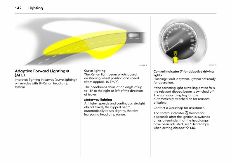
142 Lighting
Picture no: 17126t.tifAdaptive Forward Lighting 3 (AFL) improves lighting in curves (curve lighting) on vehicles with Bi-Xenon headlamp system.
Picture no: Curve lightingThe Xenon light beam pivots based on steering wheel position and speed (from approx. 10 km/h).
The headlamps shine at an angle of up to 15° to the right or left of the direction of travel.
Motorway lightingAt higher speeds and continuous straight ahead travel, the dipped beam automatically raises slightly, thereby increasing headlamp range.
Picture no: 17127t.tifControl indicator B for adaptive driving lightsFlashing: Fault in system. System not ready for operation.
If the cornering light swivelling device fails, the relevant dipped beam is switched off. The corresponding fog lamp is automatically switched on for reasons of safety.
Contact a workshop for assistance.
The control indicator B flashes for 4 seconds after the ignition is switched on as a reminder that the headlamps have been adjusted, see "Headlamps when driving abroad" 3 146.
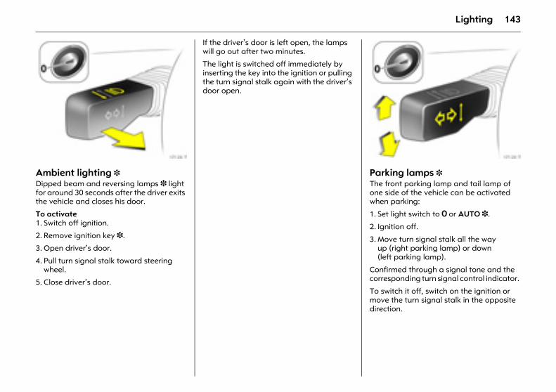
143Lighting
Picture no: 17128t.tifAmbient lighting 3 Dipped beam and reversing lamps 3 light for around 30 seconds after the driver exits the vehicle and closes his door.
To activate 1. Switch off ignition.
2. Remove ignition key 3.
3. Open driver’s door.
4. Pull turn signal stalk toward steering wheel.
5. Close driver’s door.
If the driver’s door is left open, the lamps will go out after two minutes.
The light is switched off immediately by inserting the key into the ignition or pulling the turn signal stalk again with the driver’s door open.
Picture no: 17129t.tifParking lamps 3 The front parking lamp and tail lamp of one side of the vehicle can be activated when parking:
1. Set light switch to 7 or AUTO 3.
2. Ignition off.
3. Move turn signal stalk all the way up (right parking lamp) or down (left parking lamp).
Confirmed through a signal tone and the corresponding turn signal control indicator.
To switch it off, switch on the ignition or move the turn signal stalk in the opposite direction.
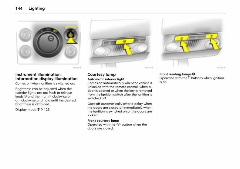
144 Lighting
Picture no: 17130t.tifInstrument illumination, Information display illumination Comes on when ignition is switched on.
Brightness can be adjusted when the exterior lights are on: Push to release knob k and then turn it clockwise or anticlockwise and hold until the desired brightness is obtained.
Display mode 3 3 129.
Picture no: 17131t.tifCourtesy lamp Automatic interior light Comes on automatically when the vehicle is unlocked with the remote control, when a door is opened or when the key is removed from the ignition switch after the ignition is switched off.
Goes off automatically after a delay when the doors are closed or immediately when the ignition is switched on or the doors are locked.
Front courtesy lamp Operated with the c button when the doors are closed.
Picture no: 17132t.tifFront reading lamps 3 Operated with the a buttons when ignition is on.
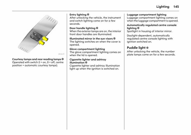
145Lighting
Picture no: 17133t.tifCourtesy lamps and rear reading lamps 3 Operated with switch (I = on, 0 = off, centre position = automatic courtesy lamps).
Entry lighting 3 After unlocking the vehicle, the instrument and switch lighting come on for a few seconds.
Door handle lighting 3 When the exterior lamps are on, the interior front door handles are illuminated.
Illuminated mirror in the sun visors 3 The lighting switches on when the cover is opened.
Glove compartment lighting The glove compartment lighting comes on when the lid is opened.
Cigarette lighter and ashtray illumination 3 Cigarette lighter and ashtray illumination light up when the ignition is switched on.
Luggage compartment lighting Luggage compartment lighting comes on when the luggage compartment is opened.
Automatically regulated centre console lighting 3 Spotlight in housing of interior mirror.
Daylight-dependent, automatically regulated centre console lighting with ignition switched on.
Puddle light 3 After unlocking the vehicle, the number plate lamps come on for a few seconds.
146 Lighting
Battery discharge protection To prevent the battery from becoming discharged, the courtesy lamp, reading lamps, luggage compartment lighting and glove compartment lighting switch off automatically 10 minutes after the ignition is switched off.
Misted light covers The inside of the light covers may mist up briefly in poor, wet and cold weather conditions, in heavy rain or after washing. The mist disappears quickly by itself; to help, switch on the lights.
Headlamps when driving abroad The asymmetrical dipped beam increases the field of vision on the passenger side of the lane.
This causes glare for oncoming traffic if the vehicle is driven in countries where traffic drives on the opposite side of the road.
Do as follows to prevent glare:
Vehicles with halogen headlamp system or Xenon headlamp system 3 Have headlamps adjusted in a workshop.
Vehicles with adaptive forward lighting 3 (AFL) 1. Pull and hold stalk for main beam on
steering wheel (headlamp flash)
2. Switch on ignition.
3. After approx. 3 seconds, an acoustic signal sounds and then AFL control indicator B flashes approx. 4 seconds.
After the switch, AFL control indicator B flashes for 4 seconds each time the ignition is switched on.
To return to asymmetrical dipped beam, pull and hold the main beam stalk again, switch on the ignition and wait for the acoustic signal. AFL control indicator B will then discontinue flashing.
Control indicator B 3 114, 3 142.
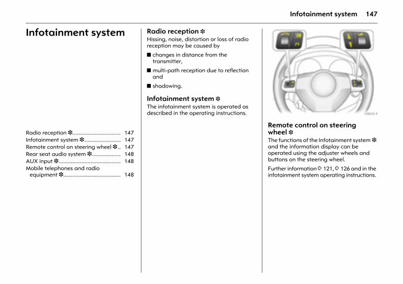
147Infotainment system
Infotainment system Radio reception 3 Hissing, noise, distortion or loss of radio reception may be caused by
z changes in distance from the transmitter,
z multi-path reception due to reflection and
z shadowing.
Infotainment system 3 The infotainment system is operated as described in the operating instructions.
Picture no: 17015t.tifRemote control on steering wheel 3 The functions of the Infotainment system 3 and the information display can be operated using the adjuster wheels and buttons on the steering wheel.
Further information 3 121, 3 126 and in the infotainment system operating instructions.
Radio reception 3................................ 147 Infotainment system 3 ........................ 147 Remote control on steering wheel 3 .. 147 Rear seat audio system 3................... 148 AUX input 3 ......................................... 148 Mobile telephones and radio
equipment 3...................................... 148
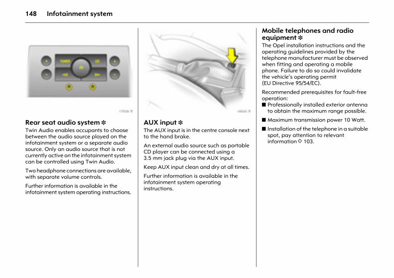
148 Infotainment system
Picture no: 17026t.tifRear seat audio system 3 Twin Audio enables occupants to choose between the audio source played on the infotainment system or a separate audio source. Only an audio source that is not currently active on the infotainment system can be controlled using Twin Audio.
Two headphone connections are available, with separate volume controls.
Further information is available in the infotainment system operating instructions.
Picture no: 18505t.tifAUX input 3 The AUX input is in the centre console next to the hand brake.
An external audio source such as portable CD player can be connected using a 3.5 mm jack plug via the AUX input.
Keep AUX input clean and dry at all times.
Further information is available in the infotainment system operating instructions.
Mobile telephones and radio equipment 3 The Opel installation instructions and the operating guidelines provided by the telephone manufacturer must be observed when fitting and operating a mobile phone. Failure to do so could invalidate the vehicle’s operating permit (EU Directive 95/54/EC).
Recommended prerequisites for fault-free operation:z Professionally installed exterior antenna
to obtain the maximum range possible.
z Maximum transmission power 10 Watt.
z Installation of the telephone in a suitable spot, pay attention to relevant information 3 103.
149Infotainment system
Obtain advice on predetermined installation locations for the external antenna and equipment holder and ways of using devices with transmission power of more than 10 watts.
We recommend that you consult your Opel Service Partner, who will have brackets and various installation kits available as accessories and will install them in accordance with regulations.
Use of a handsfree attachment without external antenna with mobile telephone standards GSM 900/1800/1900 and UMTS is only permitted if the maximum transmission power of the mobile telephone is 2 watts for GSM 900 or 1 watt for the other types.
For reasons of safety, we recommend that you do not use the phone while driving. Even use of a handsfree set can be a distraction while driving. Be sure to observe any country-specific regulations.
9 Warning
Mobile phones that do not comply with the above-mentioned mobile phone standard and radio equipment must only be operated using an antenna that is attached to the exterior of the vehicle.
Caution
Mobile phones and radio equipment may cause malfunctions in the vehicle electronics if they are operated in the vehicle without the external antenna unless the above-mentioned regulations are complied with.
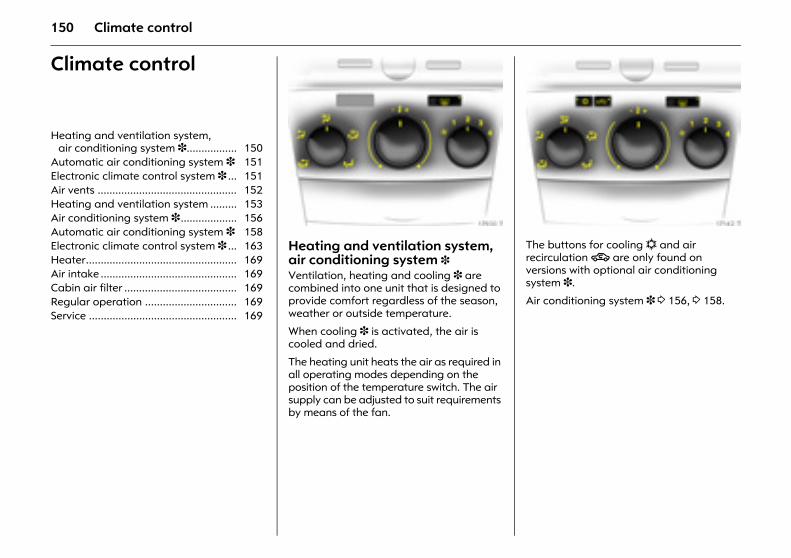
150 Climate control
Climate control
Picture no: 17930t.tifHeating and ventilation system, air conditioning system 3 Ventilation, heating and cooling 3 are combined into one unit that is designed to provide comfort regardless of the season, weather or outside temperature.
When cooling 3 is activated, the air is cooled and dried.
The heating unit heats the air as required in all operating modes depending on the position of the temperature switch. The air supply can be adjusted to suit requirements by means of the fan.
Picture no: 17142t.tifThe buttons for cooling n and air recirculation 4 are only found on versions with optional air conditioning system 3.
Air conditioning system 3 3 156, 3 158.
Heating and ventilation system, air conditioning system 3................. 150
Automatic air conditioning system 3 151 Electronic climate control system 3 ... 151 Air vents ............................................... 152 Heating and ventilation system ......... 153 Air conditioning system 3................... 156 Automatic air conditioning system 3 158 Electronic climate control system 3 ... 163 Heater................................................... 169 Air intake .............................................. 169 Cabin air filter ...................................... 169 Regular operation ............................... 169 Service .................................................. 169
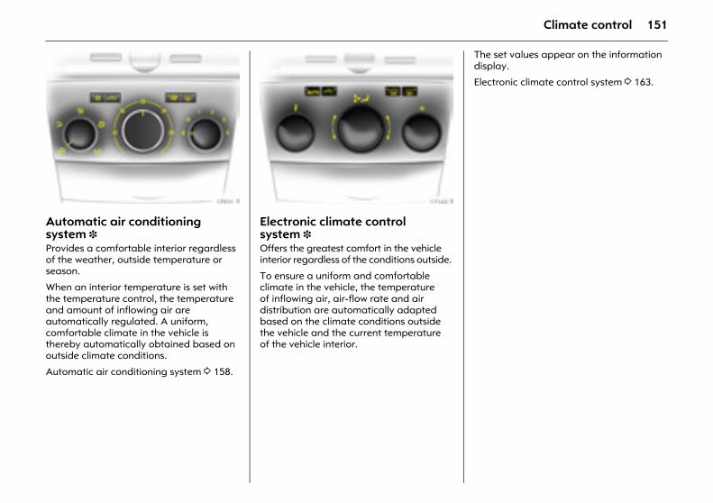
151Climate control
Picture no: 17931t.tifAutomatic air conditioning system 3 Provides a comfortable interior regardless of the weather, outside temperature or season.
When an interior temperature is set with the temperature control, the temperature and amount of inflowing air are automatically regulated. A uniform, comfortable climate in the vehicle is thereby automatically obtained based on outside climate conditions.
Automatic air conditioning system 3 158.
Picture no: 17143t.tifElectronic climate control system 3 Offers the greatest comfort in the vehicle interior regardless of the conditions outside.
To ensure a uniform and comfortable climate in the vehicle, the temperature of inflowing air, air-flow rate and air distribution are automatically adapted based on the climate conditions outside the vehicle and the current temperature of the vehicle interior.
The set values appear on the information display.
Electronic climate control system 3 163.
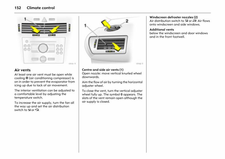
152 Climate control
Picture no: 17151t.tifAir vents At least one air vent must be open while cooling 3 (air conditioning compressor) is on in order to prevent the evaporator from icing up due to lack of air movement.
The interior ventilation can be adjusted to a comfortable level by adjusting the temperature switch.
To increase the air supply, turn the fan all the way up and set the air distribution switch to M or L.
Picture no: 17152t.tifCentre and side air vents (1) Open nozzle: move vertical knurled wheel downwards.
Aim the flow of air by turning the horizontal adjuster wheel.
To close the vent, turn the vertical adjuster wheel fully up. The symbol 0 appears. The slats of the vent remain open although the air supply is closed.
Windscreen defroster nozzles (2) Air distribution switch to l or J: Air flows onto windscreen and side windows.
Additional vents below the windscreen and door windows and in the front footwell.
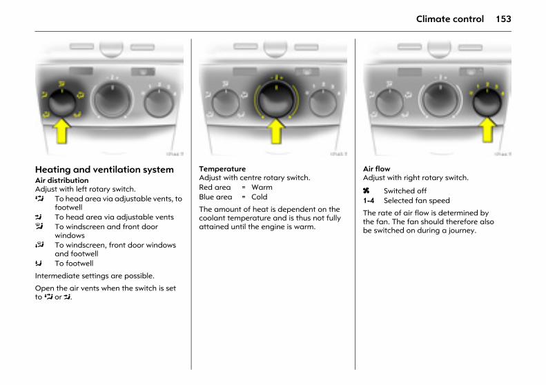
153Climate control
Picture no: 17144t.tifHeating and ventilation system Air distribution Adjust with left rotary switch.
Intermediate settings are possible.
Open the air vents when the switch is set to L or M.
Picture no: 17145t.tifTemperature Adjust with centre rotary switch.
The amount of heat is dependent on the coolant temperature and is thus not fully attained until the engine is warm.
Picture no: 17146t.tifAir flow Adjust with right rotary switch.
The rate of air flow is determined by the fan. The fan should therefore also be switched on during a journey.
L To head area via adjustable vents, to footwell
M To head area via adjustable ventsl To windscreen and front door
windowsJ To windscreen, front door windows
and footwellK To footwell
Red area = WarmBlue area = Cold
x Switched off1-4 Selected fan speed
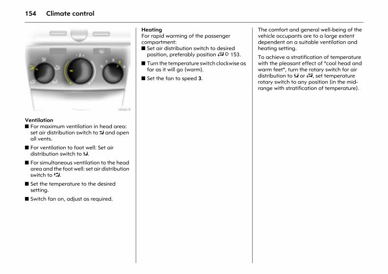
154 Climate control
Picture no: 17153t.tifVentilation z For maximum ventilation in head area:
set air distribution switch to M and open all vents.
z For ventilation to foot well: Set air distribution switch to K.
z For simultaneous ventilation to the head area and the foot well: set air distribution switch to L.
z Set the temperature to the desired setting.
z Switch fan on, adjust as required.
Heating For rapid warming of the passenger compartment: z Set air distribution switch to desired
position, preferably position J 3 153.
z Turn the temperature switch clockwise as far as it will go (warm).
z Set the fan to speed 3.
The comfort and general well-being of the vehicle occupants are to a large extent dependent on a suitable ventilation and heating setting.
To achieve a stratification of temperature with the pleasant effect of "cool head and warm feet", turn the rotary switch for air distribution to K or J, set temperature rotary switch to any position (in the mid-range with stratification of temperature).
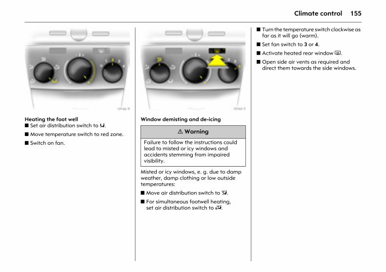
155Climate control
Picture no: 17154t.tifHeating the foot well z Set air distribution switch to K.
z Move temperature switch to red zone.
z Switch on fan.
Picture no: 17155t.tifWindow demisting and de-icing
Misted or icy windows, e. g. due to damp weather, damp clothing or low outside temperatures:
z Move air distribution switch to l.
z For simultaneous footwell heating, set air distribution switch to J.
z Turn the temperature switch clockwise as far as it will go (warm).
z Set fan switch to 3 or 4.
z Activate heated rear window Ü.
z Open side air vents as required and direct them towards the side windows.
9 Warning
Failure to follow the instructions could lead to misted or icy windows and accidents stemming from impaired visibility.

156 Climate control
Air conditioning system 3 As a supplement to the heating and ventilation system, the air conditioning system cools and dehumidifies (dries) inflowing air.
If cooling or dehumidification is not desired, switch off cooling in order to save fuel.
Cooling switches off automatically at low outside temperatures.
Picture no: 17149t.tifCooling n Only operate with the engine and fan running. Activate or deactivate with the n button.
When cooling (AC compressor) is active, air is cooled and dehumidified. If cooling or dehumidification is not desired, switch off cooling in order to save fuel.
Cooling switches off automatically at low outside temperatures.
When cooling is on condensation forms, which is expelled from the underside of the vehicle.
Picture no: 17150t.tifAir recirculation system 4 The air recirculation system is activated or deactivated by pressing the 4 button.
If fumes or unpleasant odours penetrate from outside: temporarily switch on air recirculation system 4.
To increase the cooling power at high outside temperatures, temporarily switch on the air recirculation system.
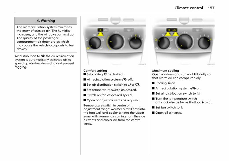
157Climate control
Air distribution to l: the air recirculation system is automatically switched off to speed up window demisting and prevent fogging. Picture no: 17156t.tif
Comfort setting z Set cooling n as desired.
z Air recirculation system 4 off.
z Set air distribution switch to M or L.
z Set temperature switch as desired.
z Switch on fan at desired speed.
z Open or adjust air vents as required.
Temperature switch in centre of adjustment range: warmer air will flow into the foot well and cooler air into the upper zone, with warmer air coming from the side air vents and cooler air from the centre vents.
Picture no: 17157t.tifMaximum cooling Open windows and sun roof 3 briefly so that warm air can escape rapidly.
z Cooling n on.
z Air recirculation system 4 on.
z Set air distribution switch to M.
z Turn the temperature switch anticlockwise as far as it will go (cold).
z Set fan switch to 4.
z Open all air vents.
9 Warning
The air recirculation system minimises the entry of outside air. The humidity increases, and the windows can mist up. The quality of the passenger compartment air deteriorates which may cause the vehicle occupants to feel drowsy.
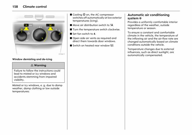
158 Climate control
Picture no: 17158t.tifWindow demisting and de-icing
Misted or icy windows, e. g. due to damp weather, damp clothing or low outside temperatures:
z Cooling n on, the AC compressor switches off automatically at low exterior temperatures (icing).
z Move air distribution switch to l.
z Turn the temperature switch clockwise.
z Set fan switch to 4.
z Open side air vents as required and direct them towards door windows.
z Switch on heated rear window Ü.
Automatic air conditioning system 3 Provides a uniformly comfortable interior regardless of the weather, outside temperature or season.
To ensure a constant and comfortable climate in the vehicle, the temperature of the inflowing air and the air-flow rate are changed automatically based on climate conditions outside the vehicle.
Temperature changes due to external influences, such as direct sunlight, are automatically compensated.
9 Warning
Failure to follow the instructions could lead to misted or icy windows and accidents stemming from impaired visibility.
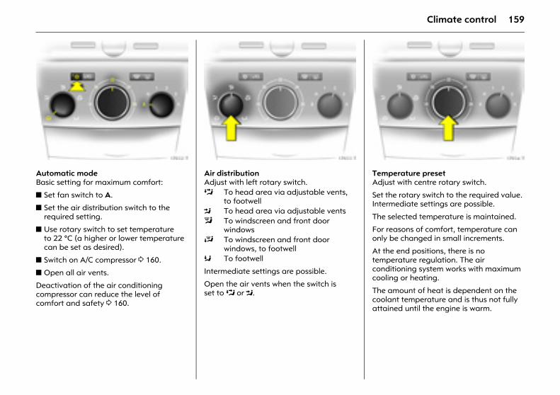
159Climate control
Picture no: 17932t.tifAutomatic mode Basic setting for maximum comfort:
z Set fan switch to A.
z Set the air distribution switch to the required setting.
z Use rotary switch to set temperature to 22 °C (a higher or lower temperature can be set as desired).
z Switch on A/C compressor 3 160.
z Open all air vents.
Deactivation of the air conditioning compressor can reduce the level of comfort and safety 3 160.
Picture no: 17933t.tifAir distribution Adjust with left rotary switch.
Intermediate settings are possible.
Open the air vents when the switch is set to L or M.
Picture no: 17934t.tifTemperature preset Adjust with centre rotary switch.
Set the rotary switch to the required value. Intermediate settings are possible.
The selected temperature is maintained.
For reasons of comfort, temperature can only be changed in small increments.
At the end positions, there is no temperature regulation. The air conditioning system works with maximum cooling or heating.
The amount of heat is dependent on the coolant temperature and is thus not fully attained until the engine is warm.
L To head area via adjustable vents, to footwell
M To head area via adjustable ventsl To windscreen and front door
windowsJ To windscreen and front door
windows, to footwellK To footwell
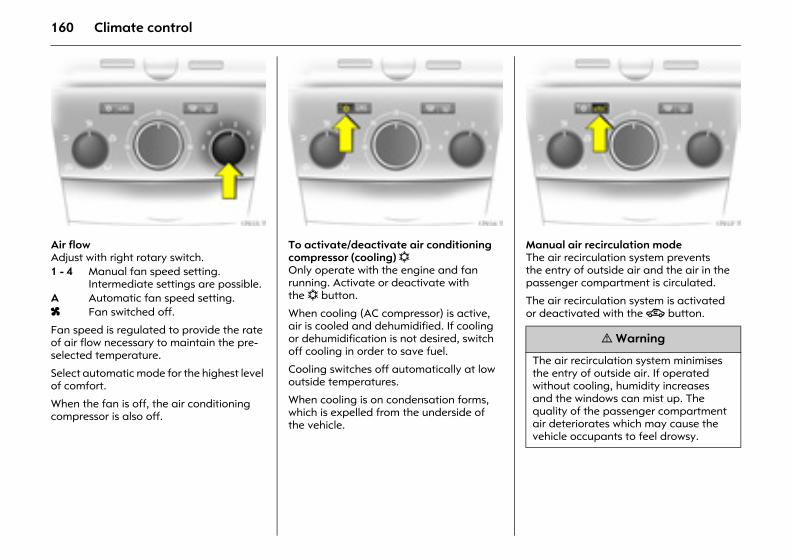
160 Climate control
Picture no: 17935t.tifAir flow Adjust with right rotary switch.
Fan speed is regulated to provide the rate of air flow necessary to maintain the pre-selected temperature.
Select automatic mode for the highest level of comfort.
When the fan is off, the air conditioning compressor is also off.
Picture no: 17936t.tifTo activate/deactivate air conditioning compressor (cooling) n Only operate with the engine and fan running. Activate or deactivate with the n button.
When cooling (AC compressor) is active, air is cooled and dehumidified. If cooling or dehumidification is not desired, switch off cooling in order to save fuel.
Cooling switches off automatically at low outside temperatures.
When cooling is on condensation forms, which is expelled from the underside of the vehicle.
Picture no: 17937t.tifManual air recirculation mode The air recirculation system prevents the entry of outside air and the air in the passenger compartment is circulated.
The air recirculation system is activated or deactivated with the 4 button.
1 - 4 Manual fan speed setting. Intermediate settings are possible.
A Automatic fan speed setting. x Fan switched off.
9 Warning
The air recirculation system minimises the entry of outside air. If operated without cooling, humidity increases and the windows can mist up. The quality of the passenger compartment air deteriorates which may cause the vehicle occupants to feel drowsy.
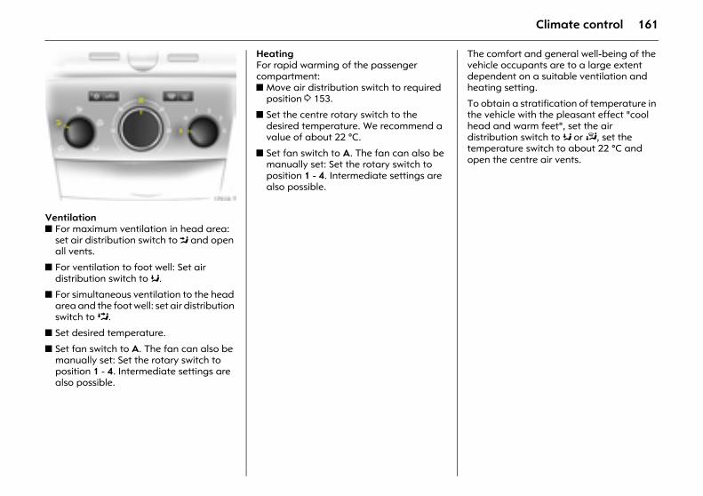
161Climate control
Picture no: 17938t.tifVentilation z For maximum ventilation in head area:
set air distribution switch to M and open all vents.
z For ventilation to foot well: Set air distribution switch to K.
z For simultaneous ventilation to the head area and the foot well: set air distribution switch to L.
z Set desired temperature.
z Set fan switch to A. The fan can also be manually set: Set the rotary switch to position 1 - 4. Intermediate settings are also possible.
Heating For rapid warming of the passenger compartment: z Move air distribution switch to required
position 3 153.
z Set the centre rotary switch to the desired temperature. We recommend a value of about 22 °C.
z Set fan switch to A. The fan can also be manually set: Set the rotary switch to position 1 - 4. Intermediate settings are also possible.
The comfort and general well-being of the vehicle occupants are to a large extent dependent on a suitable ventilation and heating setting.
To obtain a stratification of temperature in the vehicle with the pleasant effect "cool head and warm feet", set the air distribution switch to K or J, set the temperature switch to about 22 °C and open the centre air vents.
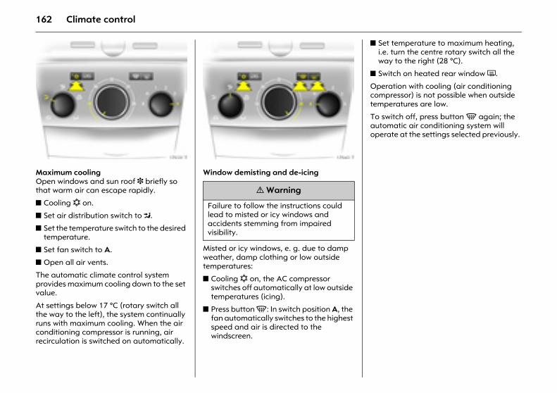
162 Climate control
Picture no: 17939t.tifMaximum cooling Open windows and sun roof 3 briefly so that warm air can escape rapidly.
z Cooling n on.
z Set air distribution switch to M.
z Set the temperature switch to the desired temperature.
z Set fan switch to A.
z Open all air vents.
The automatic climate control system provides maximum cooling down to the set value.
At settings below 17 °C (rotary switch all the way to the left), the system continually runs with maximum cooling. When the air conditioning compressor is running, air recirculation is switched on automatically.
Picture no: 17940t.tifWindow demisting and de-icing
Misted or icy windows, e. g. due to damp weather, damp clothing or low outside temperatures:
z Cooling n on, the AC compressor switches off automatically at low outside temperatures (icing).
z Press button V: In switch position A, the fan automatically switches to the highest speed and air is directed to the windscreen.
z Set temperature to maximum heating, i.e. turn the centre rotary switch all the way to the right (28 °C).
z Switch on heated rear window Ü.
Operation with cooling (air conditioning compressor) is not possible when outside temperatures are low.
To switch off, press button V again; the automatic air conditioning system will operate at the settings selected previously.
9 Warning
Failure to follow the instructions could lead to misted or icy windows and accidents stemming from impaired visibility.
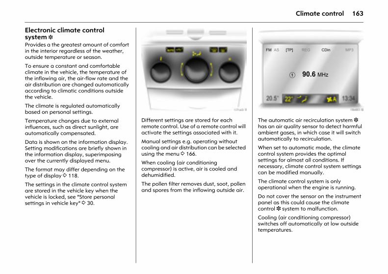
163Climate control
Electronic climate control system 3 Provides a the greatest amount of comfort in the interior regardless of the weather, outside temperature or season.
To ensure a constant and comfortable climate in the vehicle, the temperature of the inflowing air, the air-flow rate and the air distribution are changed automatically according to climatic conditions outside the vehicle.
The climate is regulated automatically based on personal settings.
Temperature changes due to external influences, such as direct sunlight, are automatically compensated.
Data is shown on the information display. Setting modifications are briefly shown in the information display, superimposing over the currently displayed menu.
The format may differ depending on the type of display 3 118.
The settings in the climate control system are stored in the vehicle key when the vehicle is locked, see "Store personal settings in vehicle key" 3 30.
Picture no: 17143t.tifDifferent settings are stored for each remote control. Use of a remote control will activate the settings associated with it.
Manual settings e.g. operating without cooling and air distribution can be selected using the menu 3 166.
When cooling (air conditioning compressor) is active, air is cooled and dehumidified.
The pollen filter removes dust, soot, pollen and spores from the inflowing outside air.
Picture no: 18483s.tifThe automatic air recirculation system 3 has an air quality sensor to detect harmful ambient gases, in which case it will switch automatically to recirculation.
When set to automatic mode, the climate control system provides the optimal settings for almost all conditions. If necessary, climate control system settings can be modified manually.
The climate control system is only operational when the engine is running.
Do not cover the sensor on the instrument panel as this could cause the climate control 3 system to malfunction.
Cooling (air conditioning compressor) switches off automatically at low outside temperatures.
FM AS [TP] REG CDin MP3
� 90.6 MHz
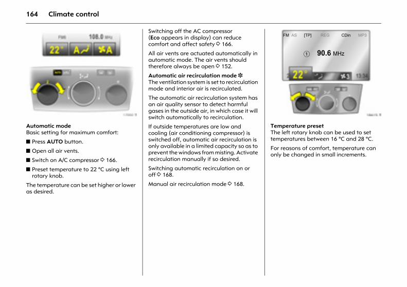
164 Climate control
Picture no: 17000t.tifAutomatic mode Basic setting for maximum comfort:
z Press AUTO button.
z Open all air vents.
z Switch on A/C compressor 3 166.
z Preset temperature to 22 °C using left rotary knob.
The temperature can be set higher or lower as desired.
Switching off the AC compressor (Eco appears in display) can reduce comfort and affect safety 3 166.
All air vents are actuated automatically in automatic mode. The air vents should therefore always be open 3 152.
Automatic air recirculation mode 3 The ventilation system is set to recirculation mode and interior air is recirculated.
The automatic air recirculation system has an air quality sensor to detect harmful gases in the outside air, in which case it will switch automatically to recirculation.
If outside temperatures are low and cooling (air conditioning compressor) is switched off, automatic air recirculation is only available in a limited capacity so as to prevent the windows from misting. Activate recirculation manually if so desired.
Switching automatic recirculation on or off 3 168.
Manual air recirculation mode 3 168.
Picture no: 18615t.tifTemperature preset The left rotary knob can be used to set temperatures between 16 °C and 28 °C.
For reasons of comfort, temperature can only be changed in small increments.
FM AS [TP] REG CDin MP3
� 90.6 MHz
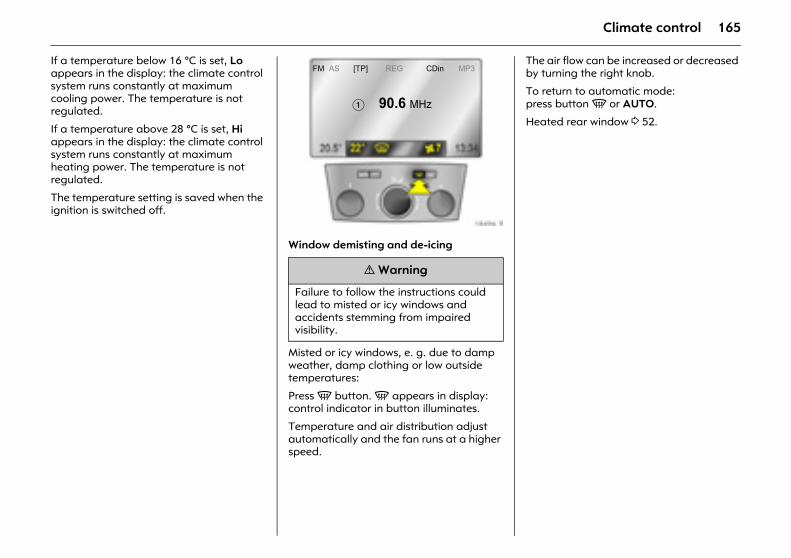
165Climate control
If a temperature below 16 °C is set, Lo appears in the display: the climate control system runs constantly at maximum cooling power. The temperature is not regulated.
If a temperature above 28 °C is set, Hi appears in the display: the climate control system runs constantly at maximum heating power. The temperature is not regulated.
The temperature setting is saved when the ignition is switched off.
Picture no: 18496t.tifWindow demisting and de-icing
Misted or icy windows, e. g. due to damp weather, damp clothing or low outside temperatures:
Press V button. V appears in display: control indicator in button illuminates.
Temperature and air distribution adjust automatically and the fan runs at a higher speed.
The air flow can be increased or decreased by turning the right knob.
To return to automatic mode: press button V or AUTO.
Heated rear window 3 52.
9 Warning
Failure to follow the instructions could lead to misted or icy windows and accidents stemming from impaired visibility.
FM AS [TP] REG CDin MP3
� 90.6 MHz
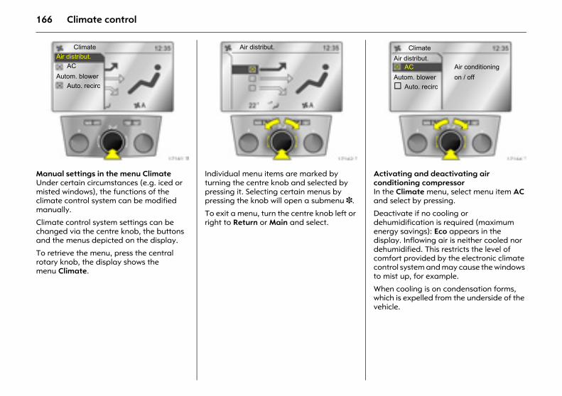
166 Climate control
Picture no: 17161t.tifManual settings in the menu ClimateUnder certain circumstances (e.g. iced or misted windows), the functions of the climate control system can be modified manually.
Climate control system settings can be changed via the centre knob, the buttons and the menus depicted on the display.
To retrieve the menu, press the central rotary knob, the display shows the menu Climate.
Picture no: 17162t.tifIndividual menu items are marked by turning the centre knob and selected by pressing it. Selecting certain menus by pressing the knob will open a submenu 3.
To exit a menu, turn the centre knob left or right to Return or Main and select.
Picture no: 17164t.tifActivating and deactivating air conditioning compressor In the Climate menu, select menu item AC and select by pressing.
Deactivate if no cooling or dehumidification is required (maximum energy savings): Eco appears in the display. Inflowing air is neither cooled nor dehumidified. This restricts the level of comfort provided by the electronic climate control system and may cause the windows to mist up, for example.
When cooling is on condensation forms, which is expelled from the underside of the vehicle.
ClimateAir distribut.
ACAutom. blower
Auto. recirc
Air distribut. ClimateAir distribut.
AC Air conditioningAutom. blower on / off
Auto. recirc
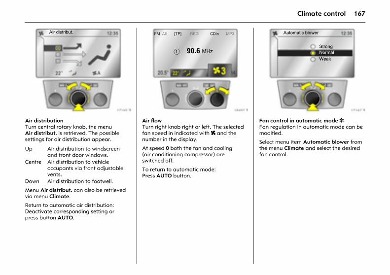
167Climate control
Picture no: 17165t.tifAir distribution Turn central rotary knob, the menu Air distribut. is retrieved. The possible settings for air distribution appear.
Menu Air distribut. can also be retrieved via menu Climate.
Return to automatic air distribution: Deactivate corresponding setting or press button AUTO.
Picture no: 18497t.tifAir flow Turn right knob right or left. The selected fan speed in indicated with x and the number in the display.
At speed 0 both the fan and cooling (air conditioning compressor) are switched off.
To return to automatic mode: Press AUTO button.
Picture no: 17167t.tifFan control in automatic mode 3 Fan regulation in automatic mode can be modified.
Select menu item Automatic blower from the menu Climate and select the desired fan control.
Up Air distribution to windscreen and front door windows.
Centre Air distribution to vehicle occupants via front adjustable vents.
Down Air distribution to footwell.
Air distribut. FM AS [TP] REG CDin MP3
� 90.6 MHz
Automatic blower
StrongNormalWeak
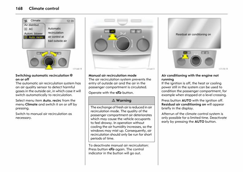
168 Climate control
Picture no: 17168t.tifSwitching automatic recirculation 3 on or offThe automatic air recirculation system has an air quality sensor to detect harmful gases in the outside air, in which case it will switch automatically to recirculation.
Select menu item Auto. recirc from the menu Climate and switch it on or off by pressing.
Switch to manual air recirculation as necessary.
Picture no: 17169t.tifManual air recirculation mode The air recirculation system prevents the entry of outside air and the air in the passenger compartment is circulated.
Operate with the 4 button.
To deactivate manual air recirculation: Press button 4 again. The control indicator in the button will go out.
Picture no: 17170t.tifAir conditioning with the engine not runningIf the ignition is off, the heat or cooling power still in the system can be used to condition the passenger compartment, for example when stopped at a level crossing.
Press button AUTO with the ignition off. Residual air conditioning on will appear briefly in the display.
Afterrun of the climate control system is only possible for a limited time. Deactivate early by pressing the AUTO button.
ClimateAir distribut.
ACAutom. blower
Auto. recirc
Automaticrecirculationair control atbad outside air
9 Warning
The exchange of fresh air is reduced in air recirculation mode. The quality of the passenger compartment air deteriorates which may cause the vehicle occupants to feel drowsy. In operation without cooling the air humidity increases, so the windows may mist up. Consequently, air recirculation should only be run for short periods of time.
Residual air conditioning on
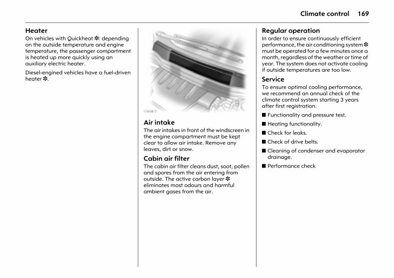
169Climate control
Heater On vehicles with Quickheat 3: depending on the outside temperature and engine temperature, the passenger compartment is heated up more quickly using an auxiliary electric heater.
Diesel-engined vehicles have a fuel-driven heater 3.
Picture no: 17438t.tifAir intake The air intakes in front of the windscreen in the engine compartment must be kept clear to allow air intake. Remove any leaves, dirt or snow.
Cabin air filter The cabin air filter cleans dust, soot, pollen and spores from the air entering from outside. The active carbon layer 3 eliminates most odours and harmful ambient gases from the air.
Regular operationIn order to ensure continuously efficient performance, the air conditioning system 3 must be operated for a few minutes once a month, regardless of the weather or time of year. The system does not activate cooling if outside temperatures are too low.
Service To ensure optimal cooling performance, we recommend an annual check of the climate control system starting 3 years after first registration.
z Functionality and pressure test.
z Heating functionality.
z Check for leaks.
z Check of drive belts.
z Cleaning of condenser and evaporator drainage.
z Performance check
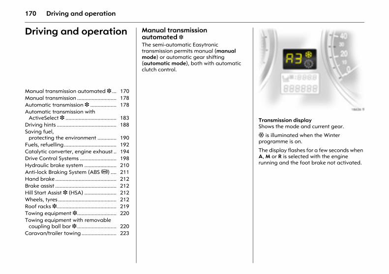
170 Driving and operation
Driving and operation Manual transmission automated 3 The semi-automatic Easytronic transmission permits manual (manual mode) or automatic gear shifting (automatic mode), both with automatic clutch control.
Picture no: 18626t.tifTransmission displayShows the mode and current gear.
T is illuminated when the Winter programme is on.
The display flashes for a few seconds when A, M or R is selected with the engine running and the foot brake not activated.
Manual transmission automated 3 ... 170 Manual transmission ........................... 178 Automatic transmission 3 .................. 178 Automatic transmission with
ActiveSelect 3 ................................... 183 Driving hints ......................................... 188 Saving fuel,
protecting the environment ............. 190 Fuels, refuelling.................................... 192 Catalytic converter, engine exhaust .. 194 Drive Control Systems ......................... 198 Hydraulic brake system ...................... 210 Anti-lock Braking System (ABS u) .... 211 Hand brake .......................................... 212 Brake assist .......................................... 212 Hill Start Assist 3 (HSA) ...................... 212 Wheels, tyres ........................................ 212 Roof racks 3......................................... 219 Towing equipment 3........................... 220 Towing equipment with removable
coupling ball bar 3 ........................... 220 Caravan/trailer towing ........................ 223
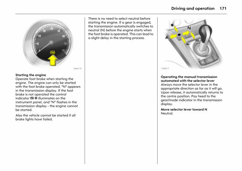
171Driving and operation
Picture no: 18442t.tifStarting the engineOperate foot brake when starting the engine. The engine can only be started with the foot brake operated. "N" appears in the transmission display. If the foot brake is not operated the control indicator j 3 illuminates on the instrument panel, and "N" flashes in the transmission display - the engine cannot be started.
Also the vehicle cannot be started if all brake lights have failed.
There is no need to select neutral before starting the engine. If a gear is engaged, the transmission automatically switches to neutral (N) before the engine starts when the foot brake is operated. This can lead to a slight delay in the starting process.
Picture no: 17002t.tifOperating the manual transmission automated with the selector leverAlways move the selector lever in the appropriate direction as far as it will go. Upon release, it automatically returns to the centre position. Pay heed to the gear/mode indicator in the transmission display.
Move selector lever toward NNeutral.
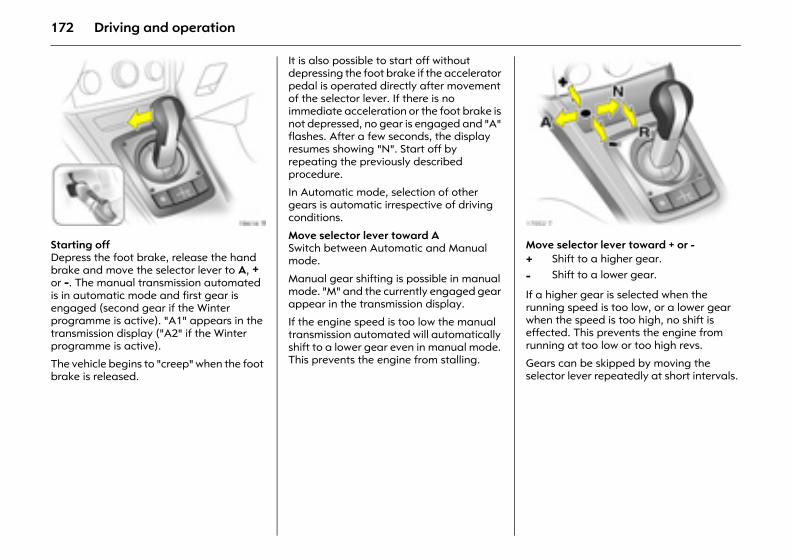
172 Driving and operation
Picture no: 18616t.tifStarting offDepress the foot brake, release the hand brake and move the selector lever to A, + or -. The manual transmission automated is in automatic mode and first gear is engaged (second gear if the Winter programme is active). "A1" appears in the transmission display ("A2" if the Winter programme is active).
The vehicle begins to "creep" when the foot brake is released.
It is also possible to start off without depressing the foot brake if the accelerator pedal is operated directly after movement of the selector lever. If there is no immediate acceleration or the foot brake is not depressed, no gear is engaged and "A" flashes. After a few seconds, the display resumes showing "N". Start off by repeating the previously described procedure.
In Automatic mode, selection of other gears is automatic irrespective of driving conditions.
Move selector lever toward ASwitch between Automatic and Manual mode.
Manual gear shifting is possible in manual mode. "M" and the currently engaged gear appear in the transmission display.
If the engine speed is too low the manual transmission automated will automatically shift to a lower gear even in manual mode. This prevents the engine from stalling.
Picture no: 17002t.tifMove selector lever toward + or -
If a higher gear is selected when the running speed is too low, or a lower gear when the speed is too high, no shift is effected. This prevents the engine from running at too low or too high revs.
Gears can be skipped by moving the selector lever repeatedly at short intervals.
+ Shift to a higher gear.
- Shift to a lower gear.
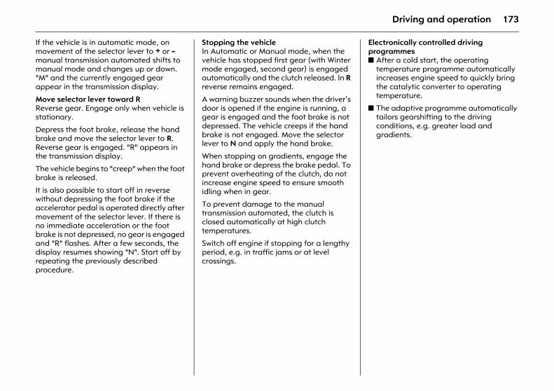
173Driving and operation
If the vehicle is in automatic mode, on movement of the selector lever to + or - manual transmission automated shifts to manual mode and changes up or down. "M" and the currently engaged gear appear in the transmission display.
Move selector lever toward RReverse gear. Engage only when vehicle is stationary.
Depress the foot brake, release the hand brake and move the selector lever to R. Reverse gear is engaged. "R" appears in the transmission display.
The vehicle begins to "creep" when the foot brake is released.
It is also possible to start off in reverse without depressing the foot brake if the accelerator pedal is operated directly after movement of the selector lever. If there is no immediate acceleration or the foot brake is not depressed, no gear is engaged and "R" flashes. After a few seconds, the display resumes showing "N". Start off by repeating the previously described procedure.
Stopping the vehicle In Automatic or Manual mode, when the vehicle has stopped first gear (with Winter mode engaged, second gear) is engaged automatically and the clutch released. In R reverse remains engaged.
A warning buzzer sounds when the driver’s door is opened if the engine is running, a gear is engaged and the foot brake is not depressed. The vehicle creeps if the hand brake is not engaged. Move the selector lever to N and apply the hand brake.
When stopping on gradients, engage the hand brake or depress the brake pedal. To prevent overheating of the clutch, do not increase engine speed to ensure smooth idling when in gear.
To prevent damage to the manual transmission automated, the clutch is closed automatically at high clutch temperatures.
Switch off engine if stopping for a lengthy period, e.g. in traffic jams or at level crossings.
Electronically controlled driving programmesz After a cold start, the operating
temperature programme automatically increases engine speed to quickly bring the catalytic converter to operating temperature.
z The adaptive programme automatically tailors gearshifting to the driving conditions, e.g. greater load and gradients.
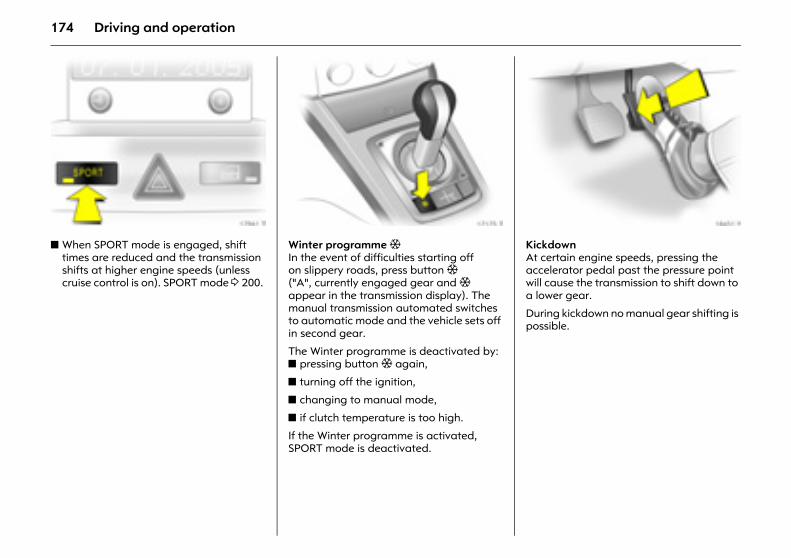
174 Driving and operation
Picture no: 17961t.tifz When SPORT mode is engaged, shift
times are reduced and the transmission shifts at higher engine speeds (unless cruise control is on). SPORT mode 3 200.
Picture no: 17175t.tifWinter programme T In the event of difficulties starting off on slippery roads, press button T ("A", currently engaged gear and T appear in the transmission display). The manual transmission automated switches to automatic mode and the vehicle sets off in second gear.
The Winter programme is deactivated by: z pressing button T again,
z turning off the ignition,
z changing to manual mode,
z if clutch temperature is too high.
If the Winter programme is activated, SPORT mode is deactivated.
Picture no: 18451s.tifKickdown At certain engine speeds, pressing the accelerator pedal past the pressure point will cause the transmission to shift down to a lower gear.
During kickdown no manual gear shifting is possible.
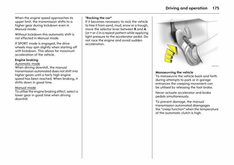
175Driving and operation
When the engine speed approaches its upper limit, the transmission shifts to a higher gear during kickdown even in Manual mode.
Without kickdown this automatic shift is not effected in Manual mode.
If SPORT mode is engaged, the drive wheels may spin slightly when starting off with kickdown. This allows for maximum acceleration of the vehicle.
Engine braking Automatic modeWhen driving downhill, the manual transmission automated does not shift into higher gears until a fairly high engine speed has been reached. When braking, it shifts down in good time.
Manual modeTo utilise the engine braking effect, select a lower gear in good time when driving downhill.
"Rocking the car" If it becomes necessary to rock the vehicle to free it from sand, mud, snow or a trough, move the selector lever between R and A (or + or -) in a repeat pattern while applying light pressure to the accelerator pedal. Do not race the engine and avoid sudden acceleration.
Picture no: 18230s.tifManoeuvring the vehicle To manoeuvre the vehicle back and forth during attempts to park or in garage entrances the creeping movement can be utilised by releasing the foot brake.
Never actuate accelerator and brake pedals simultaneously.
To prevent damage, the manual transmission automated disengages the "creep function" when the temperature of the automatic clutch is high.
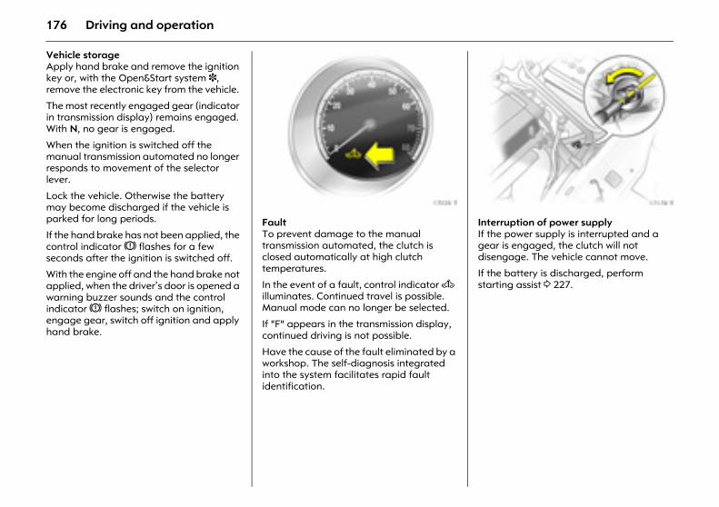
176 Driving and operation
Vehicle storageApply hand brake and remove the ignition key or, with the Open&Start system 3, remove the electronic key from the vehicle.
The most recently engaged gear (indicator in transmission display) remains engaged. With N, no gear is engaged.
When the ignition is switched off the manual transmission automated no longer responds to movement of the selector lever.
Lock the vehicle. Otherwise the battery may become discharged if the vehicle is parked for long periods.
If the hand brake has not been applied, the control indicator R flashes for a few seconds after the ignition is switched off.
With the engine off and the hand brake not applied, when the driver’s door is opened a warning buzzer sounds and the control indicator R flashes; switch on ignition, engage gear, switch off ignition and apply hand brake.
Picture no: 17028t.tifFault To prevent damage to the manual transmission automated, the clutch is closed automatically at high clutch temperatures.
In the event of a fault, control indicator A illuminates. Continued travel is possible. Manual mode can no longer be selected.
If "F" appears in the transmission display, continued driving is not possible.
Have the cause of the fault eliminated by a workshop. The self-diagnosis integrated into the system facilitates rapid fault identification.
Picture no: 17178t.tifInterruption of power supply If the power supply is interrupted and a gear is engaged, the clutch will not disengage. The vehicle cannot move.
If the battery is discharged, perform starting assist 3 227.
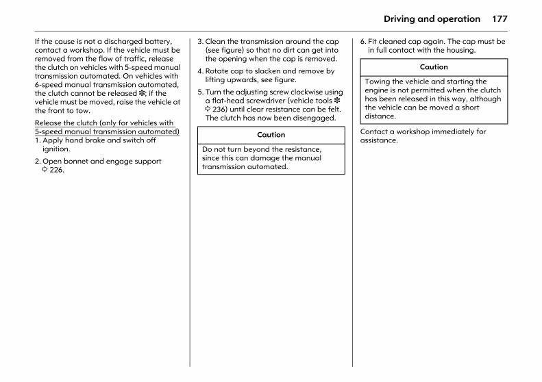
177Driving and operation
If the cause is not a discharged battery, contact a workshop. If the vehicle must be removed from the flow of traffic, release the clutch on vehicles with 5-speed manual transmission automated. On vehicles with 6-speed manual transmission automated, the clutch cannot be released 3; if the vehicle must be moved, raise the vehicle at the front to tow.
Release the clutch (only for vehicles with 5-speed manual transmission automated)1. Apply hand brake and switch off
ignition.
2. Open bonnet and engage support 3 226.
3. Clean the transmission around the cap (see figure) so that no dirt can get into the opening when the cap is removed.
4. Rotate cap to slacken and remove by lifting upwards, see figure.
5. Turn the adjusting screw clockwise using a flat-head screwdriver (vehicle tools 3 3 236) until clear resistance can be felt. The clutch has now been disengaged.
6. Fit cleaned cap again. The cap must be in full contact with the housing.
Contact a workshop immediately for assistance.
Caution
Do not turn beyond the resistance, since this can damage the manual transmission automated.
Caution
Towing the vehicle and starting the engine is not permitted when the clutch has been released in this way, although the vehicle can be moved a short distance.
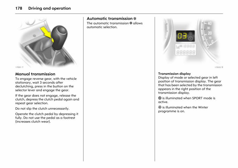
178 Driving and operation
Picture no: 17001t.tifManual transmissionTo engage reverse gear, with the vehicle stationary, wait 3 seconds after declutching, press in the button on the selector lever and engage the gear.
If the gear does not engage, release the clutch, depress the clutch pedal again and repeat gear selection.
Do not slip the clutch unnecessarily.
Operate the clutch pedal by depressing it fully. Do not use the pedal as a footrest (increases clutch wear).
Automatic transmission 3 The automatic transmission 3 allows automatic selection.
Picture no: 17022t.tifTransmission display Display of mode or selected gear in left position of transmission display. The gear that has been selected by the transmission appears in the right position of the transmission display.
1 is illuminated when SPORT mode is active.
T is illuminated when the Winter programme is on.
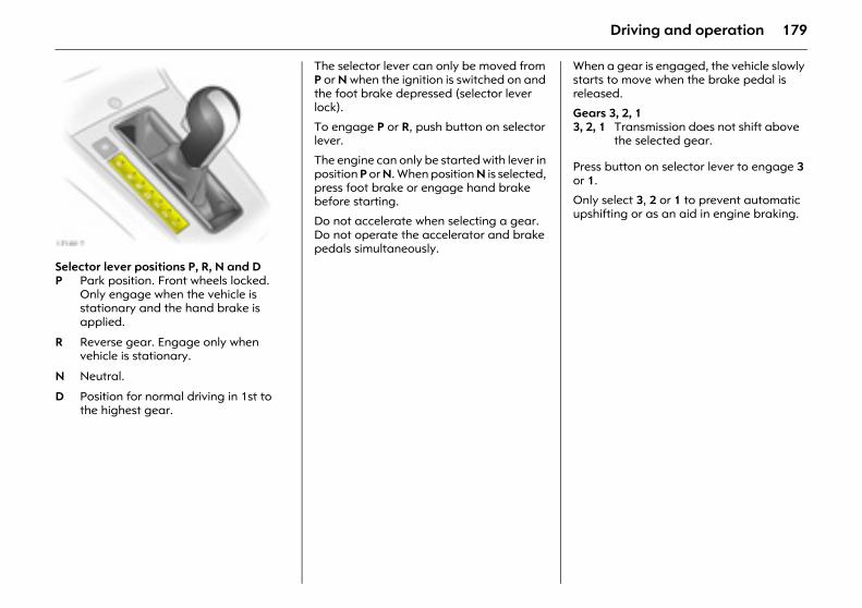
179Driving and operation
Picture no: 17189t.tifSelector lever positions P, R, N and D
The selector lever can only be moved from P or N when the ignition is switched on and the foot brake depressed (selector lever lock).
To engage P or R, push button on selector lever.
The engine can only be started with lever in position P or N. When position N is selected, press foot brake or engage hand brake before starting.
Do not accelerate when selecting a gear. Do not operate the accelerator and brake pedals simultaneously.
When a gear is engaged, the vehicle slowly starts to move when the brake pedal is released.
Gears 3, 2, 1
Press button on selector lever to engage 3 or 1.
Only select 3, 2 or 1 to prevent automatic upshifting or as an aid in engine braking.
P Park position. Front wheels locked. Only engage when the vehicle is stationary and the hand brake is applied.
R Reverse gear. Engage only when vehicle is stationary.
N Neutral.
D Position for normal driving in 1st to the highest gear.
3, 2, 1 Transmission does not shift above the selected gear.
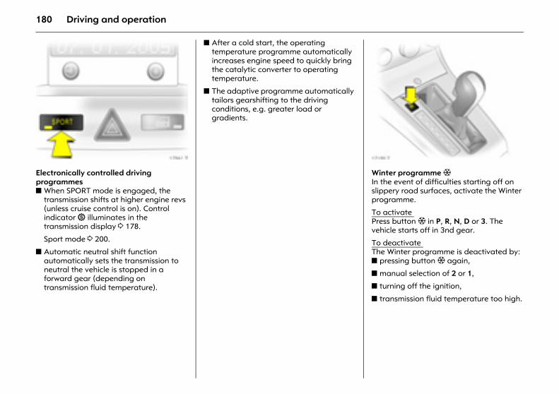
180 Driving and operation
Picture no: 17961t.tifElectronically controlled driving programmes z When SPORT mode is engaged, the
transmission shifts at higher engine revs (unless cruise control is on). Control indicator 1 illuminates in the transmission display 3 178.
Sport mode 3 200.
z Automatic neutral shift function automatically sets the transmission to neutral the vehicle is stopped in a forward gear (depending on transmission fluid temperature).
z After a cold start, the operating temperature programme automatically increases engine speed to quickly bring the catalytic converter to operating temperature.
z The adaptive programme automatically tailors gearshifting to the driving conditions, e.g. greater load or gradients.
Picture no: 17190t.tifWinter programme T In the event of difficulties starting off on slippery road surfaces, activate the Winter programme.
To activate Press button T in P, R, N, D or 3. The vehicle starts off in 3nd gear.
To deactivate The Winter programme is deactivated by: z pressing button T again,
z manual selection of 2 or 1,
z turning off the ignition,
z transmission fluid temperature too high.
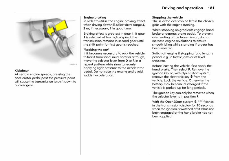
181Driving and operation
Picture no: 18451s.tifKickdown At certain engine speeds, pressing the accelerator pedal past the pressure point will cause the transmission to shift down to a lower gear.
Engine braking In order to utilise the engine braking effect when driving downhill, select drive range 3, 2 or, if necessary, 1 in good time.
Braking effect is greatest in gear 1. If gear 1 is selected at too high a speed, the transmission remains in second gear until the shift point for first gear is reached.
"Rocking the car" If it becomes necessary to rock the vehicle to free it from sand, mud, snow or a trough, move the selector lever from D to R in a repeat pattern while simultaneously applying light pressure to the accelerator pedal. Do not race the engine and avoid sudden acceleration.
Stopping the vehicle The selector lever can be left in the chosen gear with the engine running.
When stopping on gradients engage hand brake or depress brake pedal. To prevent overheating of the transmission, do not increase engine revolutions to ensure smooth idling while standing if a gear has been selected.
Switch off engine if stopping for a lengthy period, e.g. in traffic jams or at level crossings.
Before leaving the vehicle, first apply the hand brake. Then select P. Remove the ignition key or, with Open&Start system, remove the electronic key 3 from the vehicle. Lock the vehicle. Otherwise the battery may become discharged if the vehicle is parked up for long periods.
The ignition key can only be removed when the selector lever is in position P.
With the Open&Start system 3, "P" flashes in the transmission display for 10 seconds when the ignition is switched off if P has not been engaged or the hand brake has not been applied.
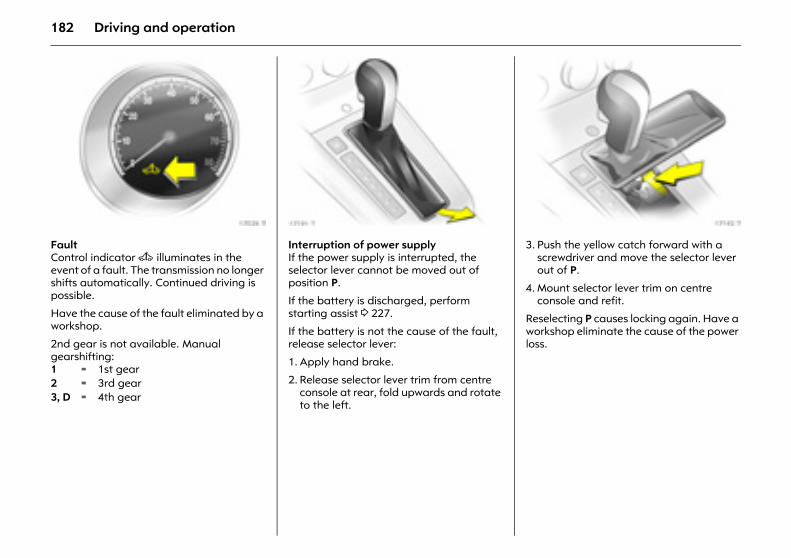
182 Driving and operation
Picture no: 17028t.tifFault Control indicator A illuminates in the event of a fault. The transmission no longer shifts automatically. Continued driving is possible.
Have the cause of the fault eliminated by a workshop.
2nd gear is not available. Manual gearshifting:
Picture no: 17191t.tifInterruption of power supply If the power supply is interrupted, the selector lever cannot be moved out of position P.
If the battery is discharged, perform starting assist 3 227.
If the battery is not the cause of the fault, release selector lever:
1. Apply hand brake.
2. Release selector lever trim from centre console at rear, fold upwards and rotate to the left.
Picture no: 17192t.tif3. Push the yellow catch forward with a
screwdriver and move the selector lever out of P.
4. Mount selector lever trim on centre console and refit.
Reselecting P causes locking again. Have a workshop eliminate the cause of the power loss.
1 = 1st gear2 = 3rd gear3, D = 4th gear
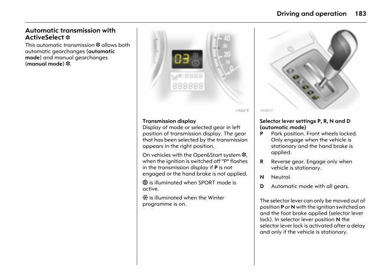
183Driving and operation
Automatic transmission with ActiveSelect 3 This automatic transmission 3 allows both automatic gearchanges (automatic mode) and manual gearchanges (manual mode) 3.
Picture no: 17022t.tifTransmission display Display of mode or selected gear in left position of transmission display. The gear that has been selected by the transmission appears in the right position.
On vehicles with the Open&Start system 3, when the ignition is switched off "P" flashes in the transmission display if P is not engaged or the hand brake is not applied.
1 is illuminated when SPORT mode is active.
T is illuminated when the Winter programme is on.
Picture no: 17193t.tifSelector lever settings P, R, N and D (automatic mode)
The selector lever can only be moved out of position P or N with the ignition switched on and the foot brake applied (selector lever lock). In selector lever position N the selector lever lock is activated after a delay and only if the vehicle is stationary.
P Park position. Front wheels locked. Only engage when the vehicle is stationary and the hand brake is applied.
R Reverse gear. Engage only when vehicle is stationary.
N Neutral.
D Automatic mode with all gears.
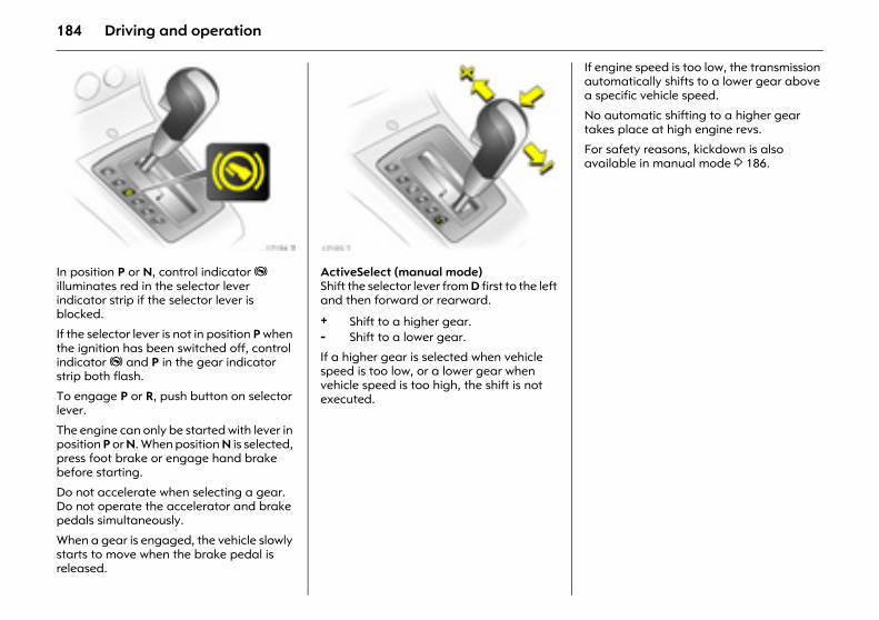
184 Driving and operation
Picture no: 17194t.tifIn position P or N, control indicator j illuminates red in the selector lever indicator strip if the selector lever is blocked.
If the selector lever is not in position P when the ignition has been switched off, control indicator j and P in the gear indicator strip both flash.
To engage P or R, push button on selector lever.
The engine can only be started with lever in position P or N. When position N is selected, press foot brake or engage hand brake before starting.
Do not accelerate when selecting a gear. Do not operate the accelerator and brake pedals simultaneously.
When a gear is engaged, the vehicle slowly starts to move when the brake pedal is released.
Picture no: 17195t.tifActiveSelect (manual mode) Shift the selector lever from D first to the left and then forward or rearward.
If a higher gear is selected when vehicle speed is too low, or a lower gear when vehicle speed is too high, the shift is not executed.
If engine speed is too low, the transmission automatically shifts to a lower gear above a specific vehicle speed.
No automatic shifting to a higher gear takes place at high engine revs.
For safety reasons, kickdown is also available in manual mode 3 186.
+ Shift to a higher gear.- Shift to a lower gear.
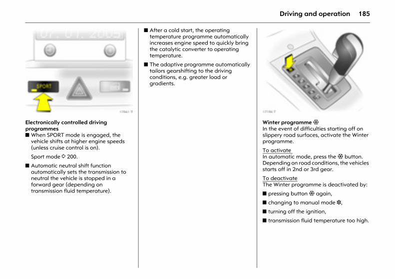
185Driving and operation
Picture no: 17961t.tifElectronically controlled driving programmes z When SPORT mode is engaged, the
vehicle shifts at higher engine speeds (unless cruise control is on).
Sport mode 3 200.
z Automatic neutral shift function automatically sets the transmission to neutral the vehicle is stopped in a forward gear (depending on transmission fluid temperature).
z After a cold start, the operating temperature programme automatically increases engine speed to quickly bring the catalytic converter to operating temperature.
z The adaptive programme automatically tailors gearshifting to the driving conditions, e.g. greater load or gradients.
Picture no: 17196t.tifWinter programme T In the event of difficulties starting off on slippery road surfaces, activate the Winter programme.
To activate In automatic mode, press the T button. Depending on road conditions, the vehicles starts off in 2nd or 3rd gear.
To deactivateThe Winter programme is deactivated by:
z pressing button T again,
z changing to manual mode 3,
z turning off the ignition,
z transmission fluid temperature too high.
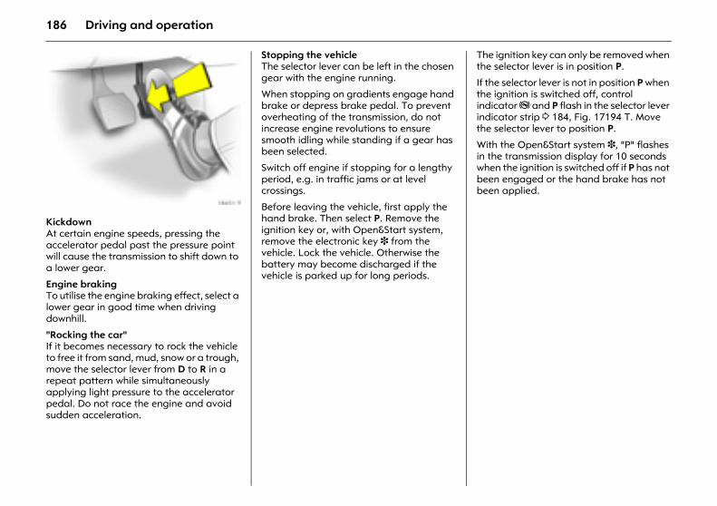
186 Driving and operation
Picture no: 18451s.tifKickdown At certain engine speeds, pressing the accelerator pedal past the pressure point will cause the transmission to shift down to a lower gear.
Engine braking To utilise the engine braking effect, select a lower gear in good time when driving downhill.
"Rocking the car" If it becomes necessary to rock the vehicle to free it from sand, mud, snow or a trough, move the selector lever from D to R in a repeat pattern while simultaneously applying light pressure to the accelerator pedal. Do not race the engine and avoid sudden acceleration.
Stopping the vehicle The selector lever can be left in the chosen gear with the engine running.
When stopping on gradients engage hand brake or depress brake pedal. To prevent overheating of the transmission, do not increase engine revolutions to ensure smooth idling while standing if a gear has been selected.
Switch off engine if stopping for a lengthy period, e.g. in traffic jams or at level crossings.
Before leaving the vehicle, first apply the hand brake. Then select P. Remove the ignition key or, with Open&Start system, remove the electronic key 3 from the vehicle. Lock the vehicle. Otherwise the battery may become discharged if the vehicle is parked up for long periods.
The ignition key can only be removed when the selector lever is in position P.
If the selector lever is not in position P when the ignition is switched off, control indicator j and P flash in the selector lever indicator strip 3 184, Fig. 17194 T. Move the selector lever to position P.
With the Open&Start system 3, "P" flashes in the transmission display for 10 seconds when the ignition is switched off if P has not been engaged or the hand brake has not been applied.
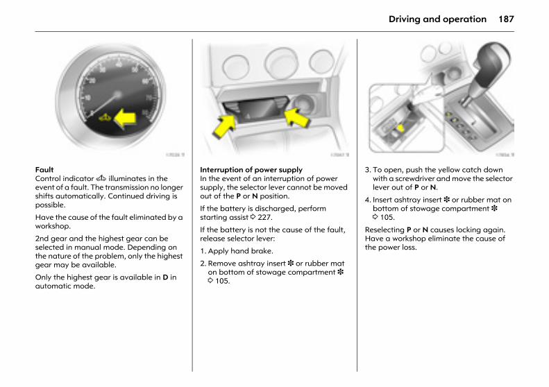
187Driving and operation
Picture no: 17028t.tifFault Control indicator A illuminates in the event of a fault. The transmission no longer shifts automatically. Continued driving is possible.
Have the cause of the fault eliminated by a workshop.
2nd gear and the highest gear can be selected in manual mode. Depending on the nature of the problem, only the highest gear may be available.
Only the highest gear is available in D in automatic mode.
Picture no: 17097t.tifInterruption of power supply In the event of an interruption of power supply, the selector lever cannot be moved out of the P or N position.
If the battery is discharged, perform starting assist 3 227.
If the battery is not the cause of the fault, release selector lever:
1. Apply hand brake.
2. Remove ashtray insert 3 or rubber mat on bottom of stowage compartment 3 3 105.
Picture no: 17856t.tif3. To open, push the yellow catch down
with a screwdriver and move the selector lever out of P or N.
4. Insert ashtray insert 3 or rubber mat on bottom of stowage compartment 3 3 105.
Reselecting P or N causes locking again. Have a workshop eliminate the cause of the power loss.
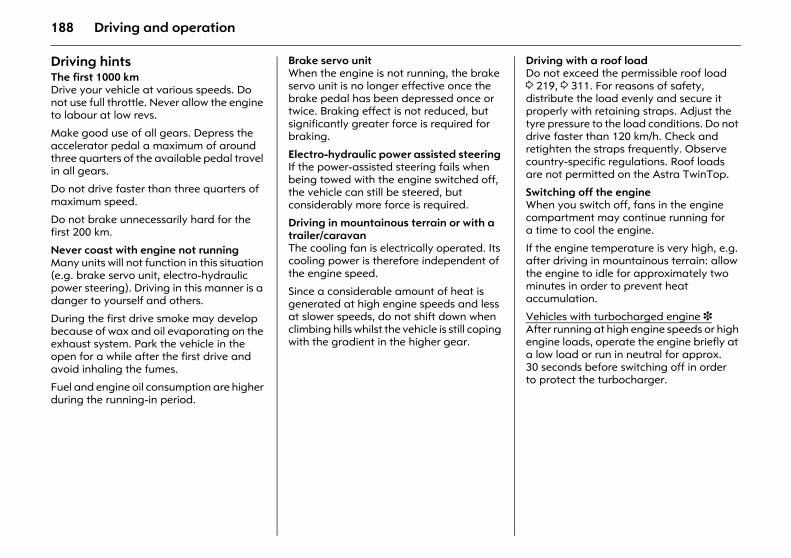
188 Driving and operation
Driving hintsThe first 1000 km Drive your vehicle at various speeds. Do not use full throttle. Never allow the engine to labour at low revs.
Make good use of all gears. Depress the accelerator pedal a maximum of around three quarters of the available pedal travel in all gears.
Do not drive faster than three quarters of maximum speed.
Do not brake unnecessarily hard for the first 200 km.
Never coast with engine not running Many units will not function in this situation (e.g. brake servo unit, electro-hydraulic power steering). Driving in this manner is a danger to yourself and others.
During the first drive smoke may develop because of wax and oil evaporating on the exhaust system. Park the vehicle in the open for a while after the first drive and avoid inhaling the fumes.
Fuel and engine oil consumption are higher during the running-in period.
Brake servo unit When the engine is not running, the brake servo unit is no longer effective once the brake pedal has been depressed once or twice. Braking effect is not reduced, but significantly greater force is required for braking.
Electro-hydraulic power assisted steering If the power-assisted steering fails when being towed with the engine switched off, the vehicle can still be steered, but considerably more force is required.
Driving in mountainous terrain or with a trailer/caravan The cooling fan is electrically operated. Its cooling power is therefore independent of the engine speed.
Since a considerable amount of heat is generated at high engine speeds and less at slower speeds, do not shift down when climbing hills whilst the vehicle is still coping with the gradient in the higher gear.
Driving with a roof load Do not exceed the permissible roof load 3 219, 3 311. For reasons of safety, distribute the load evenly and secure it properly with retaining straps. Adjust the tyre pressure to the load conditions. Do not drive faster than 120 km/h. Check and retighten the straps frequently. Observe country-specific regulations. Roof loads are not permitted on the Astra TwinTop.
Switching off the engineWhen you switch off, fans in the engine compartment may continue running for a time to cool the engine.
If the engine temperature is very high, e.g. after driving in mountainous terrain: allow the engine to idle for approximately two minutes in order to prevent heat accumulation.
Vehicles with turbocharged engine 3After running at high engine speeds or high engine loads, operate the engine briefly at a low load or run in neutral for approx. 30 seconds before switching off in order to protect the turbocharger.
189Driving and operation
Save energy – more kilometres Please observe the running-in hints on the previous page and the tips for saving energy on the following pages.
Good, technically correct and economical driving ensures maximum durability and performance for your vehicle.
Overrun cut-off The fuel supply is automatically shut off during overrun, e.g. when a gear is engaged and the accelerator pedal is not operated. Overrun cut-off is not activated if catalytic converter temperature is high.
Vehicles with turbocharged engine 3Flow-generated noises may be audible if the accelerator is released quickly on account of air flow in the turbocharger.
Engine speed Drive in a low engine speed range for each gear as much as possible.
Warming up After a cold start, the automatic transmission 3 or manual transmission automated 3 in automatic mode shifts into higher gears at higher rpm. This allows the catalytic converter to quickly reach the temperature required for optimum pollutant reduction.
Correct gear selection Engine in neutral and without revving in the lower gears. Stop-and-go traffic and driving at a speed too high for the selected gear or transmission ratio increases wear and fuel consumption.
Change down When decreasing speed, shift down into the next lowest gear. Do not slip the clutch with a high-revving engine. This is especially important when hill climbing.
Cooling fan The cooling fan is controlled via a thermoswitch and therefore only runs if necessary.
The cooling fan automatically switches on when the diesel particle filter is being cleaned 3 depending on the engine.
Pedals Do not place any objects in the foot well which could slip under the pedals and inhibit the pedal travel.
To ensure the pedal travel is uninhibited, there must be no mats in the area of the pedals.
Battery care When driving slowly or when the vehicle is stationary, e.g. in slow urban traffic, stop-and-go traffic or traffic jams, turn off all unnecessary electrical loads where possible (e.g. heated rear window, heated front seats).
Declutch when starting in order to relieve the strain on the starter and the battery.
190 Driving and operation
Saving fuel, protecting the environment Trend-setting technologyIn the development and manufacture of your vehicle, environmentally-friendly and in the main recyclable materials were used. The production methods used to make your vehicle are likewise environmentally-friendly.
Recycling of production wastes keeps the circulation of material closed. Reduction of energy and water requirements also helps to conserve natural resources.
A highly advanced design means that your vehicle can be easily disassembled at the end of its working life, and the individual materials separated for subsequent re-use.
Materials such as asbestos and cadmium are not used. The refrigerant in the air conditioning system 3 is CFC-free.
New painting techniques employ water as a solvent.
End-of-life vehicle recovery Information on end-of-life vehicle recovery centres and the recycling of end-of-life vehicles is available at www.opel.com.
Energy and environment-conscious driving z High noise levels and exhaust emissions
are often a result of driving without due attention to saving energy and protecting the environment.
z You should therefore drive with energy in mind – "more miles with less fuel".
Reduce the noise level and exhaust emissions by adopting an environment-conscious driving style. This is extremely worthwhile and improves the quality of life.
Fuel consumption depends to a great extent on your own personal driving style. The following hints are intended to help you consume fuel at a rate that is as close as possible to the specified levels 3 302.
Check your vehicle’s fuel consumption every time you refuel. This facilitates early detection of any irregularities causing increased fuel consumption.
Warming up z Full throttle and warming up at idle
speed increase wear, fuel consumption, exhaust emission, the amount of pollutant in the exhaust and the amount of noise.
z Drive off as soon as possible after starting.
Uniform speed z Hectic driving significantly increases fuel
consumption, the exhaust emissions, the proportion of pollutant in the exhaust gas and the noise level.
z Do not accelerate and brake unnecessarily. Drive at uniform speed, watching the road.
Avoid frequent starting off and stopping e.g. at traffic lights, in short distance traffic and in queues of traffic by means of clever planning. Select roads with good traffic flow.
Idling z The engine also consumes fuel when
idling.
z If you have to wait for more than one minute, it is worthwhile switching off the engine. Five minutes of idling corresponds to approximately one kilometre of driving.
191Driving and operation
Overrun z The fuel supply is automatically shut off
in overrun, e.g. when driving downhill or braking 3 189.
z To enable the overrun cut-off to come into action and save fuel, do not accelerate or declutch during overrun.
Correct gear selection z High revs increase engine wear and fuel
consumption.
z Do not race your engine. Avoid driving at high engine speeds.
Making use of the tachometer helps to save fuel. Drive in a low engine speed range for each gear as much as possible with uniform engine speeds. Drive as often as possible in top gear, select the next higher gear as soon as possible, and only change down when the engine is no longer running perfectly smoothly.
High speed z The higher the speed, the higher the
consumption and the noise level. At top speed, you consume a great deal of fuel and produce excessive noise and exhaust emissions.
z Slightly releasing the accelerator pedal results in distinct fuel savings with no major loss of speed.
Drive at no more than around three quarters of maximum speed and you will use up to 50 % less fuel, without losing a great deal of time.
Tyre pressure z Inadequate tyre pressure, leading to
higher road resistance, costs money in two ways: for more fuel and increased tyre wear.
z Regular checks (every 14 days) pay off.
Electrical loadsz The power consumption of electrical
equipment increases fuel consumption.
z Switch off all auxiliary electrical loads (e.g. air conditioning 3, heated rear window) when not needed.
Roof racks, ski-holders z Due to air resistance, a roof load
can increase fuel consumption by approx. 1 l/100 km.
z Remove them if they are not being used.
Repair and maintenance z Improper repairs or adjustment and
maintenance work can increase fuel consumption. Do not carry out work on the engine yourself.
You may out of ignorance infringe environmental laws by not disposing of materials properly.
Appropriate parts might not be recycled.
Contact with some of the materials involved may pose a health hazard.
z We recommend that repair and maintenance be entrusted to your Opel Partner.
Extreme driving conditionsz Going up steep slopes, cornering, driving
on poor roads and winter driving all increase fuel consumption.
Fuel consumption increases dramatically in urban traffic and at winter temperatures, especially on short trips when the engine operating temperature is not reached.
z Follow the above-mentioned hints to minimise consumption under such conditions.
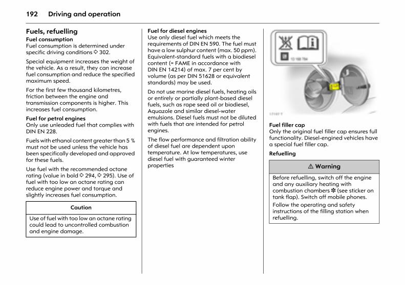
192 Driving and operation
Fuels, refuelling Fuel consumptionFuel consumption is determined under specific driving conditions 3 302.
Special equipment increases the weight of the vehicle. As a result, they can increase fuel consumption and reduce the specified maximum speed.
For the first few thousand kilometres, friction between the engine and transmission components is higher. This increases fuel consumption.
Fuel for petrol engines Only use unleaded fuel that complies with DIN EN 228.
Fuels with ethanol content greater than 5 % must not be used unless the vehicle has been specifically developed and approved for these fuels.
Use fuel with the recommended octane rating (value in bold 3 294, 3 295). Use of fuel with too low an octane rating can reduce engine power and torque and slightly increases fuel consumption.
Fuel for diesel engines Use only diesel fuel which meets the requirements of DIN EN 590. The fuel must have a low sulphur content (max. 50 ppm). Equivalent-standard fuels with a biodiesel content (= FAME in accordance with DIN EN 14214) of max. 7 per cent by volume (as per DIN 51628 or equivalent standards) may be used.
Do not use marine diesel fuels, heating oils or entirely or partially plant-based diesel fuels, such as rape seed oil or biodiesel, Aquazole and similar diesel-water emulsions. Diesel fuels must not be diluted with fuels that are intended for petrol engines.
The flow performance and filtration ability of diesel fuel are dependent upon temperature. At low temperatures, use diesel fuel with guaranteed winter properties
Picture no: 17197t.tifFuel filler cap Only the original fuel filler cap ensures full functionality. Diesel-engined vehicles have a special fuel filler cap.
Refuelling
Caution
Use of fuel with too low an octane rating could lead to uncontrolled combustion and engine damage.
9 Warning
Before refuelling, switch off the engine and any auxiliary heating with combustion chambers 3 (see sticker on tank flap). Switch off mobile phones. Follow the operating and safety instructions of the filling station when refuelling.
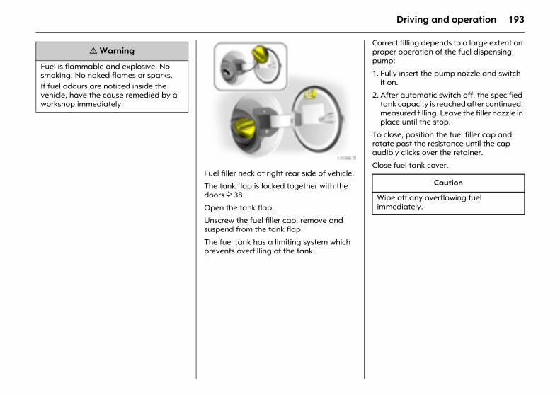
193Driving and operation
Picture no: 17198t.tifFuel filler neck at right rear side of vehicle.
The tank flap is locked together with the doors 3 38.
Open the tank flap.
Unscrew the fuel filler cap, remove and suspend from the tank flap.
The fuel tank has a limiting system which prevents overfilling of the tank.
Correct filling depends to a large extent on proper operation of the fuel dispensing pump:
1. Fully insert the pump nozzle and switch it on.
2. After automatic switch off, the specified tank capacity is reached after continued, measured filling. Leave the filler nozzle in place until the stop.
To close, position the fuel filler cap and rotate past the resistance until the cap audibly clicks over the retainer.
Close fuel tank cover.
9 Warning
Fuel is flammable and explosive. No smoking. No naked flames or sparks. If fuel odours are noticed inside the vehicle, have the cause remedied by a workshop immediately.
Caution
Wipe off any overflowing fuel immediately.
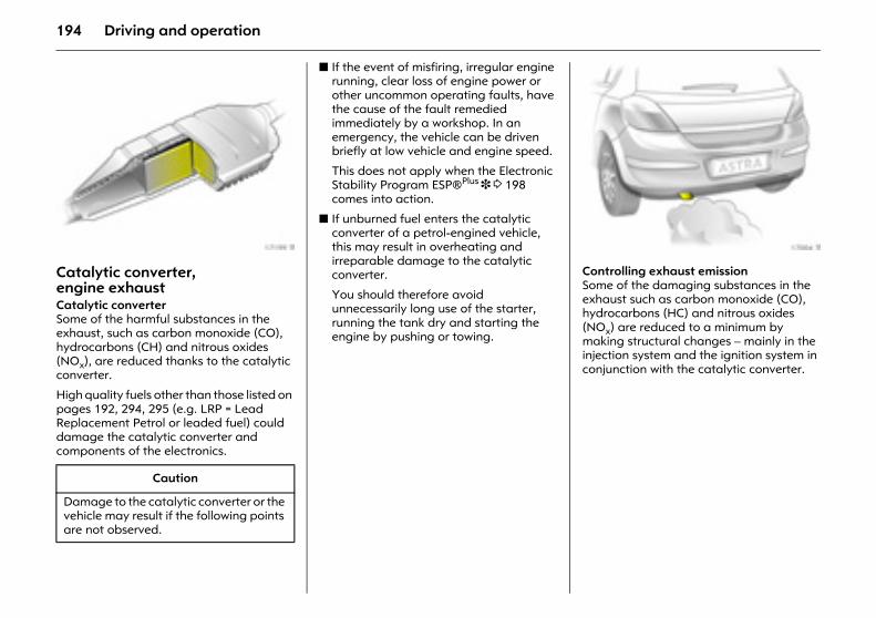
194 Driving and operation
Picture no: 17199t.tifCatalytic converter, engine exhaustCatalytic converter Some of the harmful substances in the exhaust, such as carbon monoxide (CO), hydrocarbons (CH) and nitrous oxides (NOx), are reduced thanks to the catalytic converter.
High quality fuels other than those listed on pages 192, 294, 295 (e.g. LRP = Lead Replacement Petrol or leaded fuel) could damage the catalytic converter and components of the electronics.
z If the event of misfiring, irregular engine running, clear loss of engine power or other uncommon operating faults, have the cause of the fault remedied immediately by a workshop. In an emergency, the vehicle can be driven briefly at low vehicle and engine speed.
This does not apply when the Electronic Stability Program ESP®Plus 3 3 198 comes into action.
z If unburned fuel enters the catalytic converter of a petrol-engined vehicle, this may result in overheating and irreparable damage to the catalytic converter.
You should therefore avoid unnecessarily long use of the starter, running the tank dry and starting the engine by pushing or towing.
Picture no: 17004t.tifControlling exhaust emission Some of the damaging substances in the exhaust such as carbon monoxide (CO), hydrocarbons (HC) and nitrous oxides (NOx) are reduced to a minimum by making structural changes – mainly in the injection system and the ignition system in conjunction with the catalytic converter.
Caution
Damage to the catalytic converter or the vehicle may result if the following points are not observed.
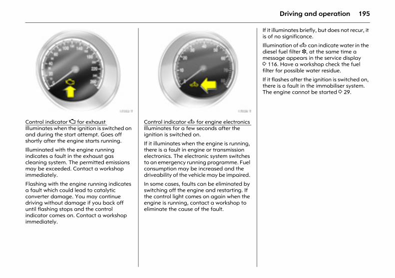
195Driving and operation
Picture no: 17352t.tifControl indicator Z for exhaust Illuminates when the ignition is switched on and during the start attempt. Goes off shortly after the engine starts running.
Illuminated with the engine running indicates a fault in the exhaust gas cleaning system. The permitted emissions may be exceeded. Contact a workshop immediately.
Flashing with the engine running indicates a fault which could lead to catalytic converter damage. You may continue driving without damage if you back off until flashing stops and the control indicator comes on. Contact a workshop immediately.
Picture no: 17028t.tifControl indicator A for engine electronics Illuminates for a few seconds after the ignition is switched on.
If it illuminates when the engine is running, there is a fault in engine or transmission electronics. The electronic system switches to an emergency running programme. Fuel consumption may be increased and the driveability of the vehicle may be impaired.
In some cases, faults can be eliminated by switching off the engine and restarting. If the control light comes on again when the engine is running, contact a workshop to eliminate the cause of the fault.
If it illuminates briefly, but does not recur, it is of no significance.
Illumination of A can indicate water in the diesel fuel filter 3, at the same time a message appears in the service display 3 116. Have a workshop check the fuel filter for possible water residue.
If it flashes after the ignition is switched on, there is a fault in the immobiliser system. The engine cannot be started 3 29.
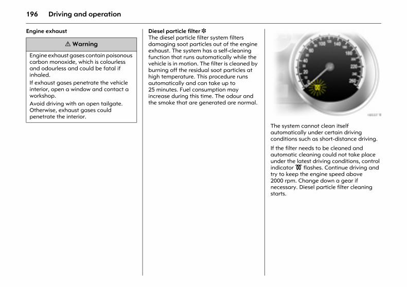
196 Driving and operation
Engine exhaust Diesel particle filter 3 The diesel particle filter system filters damaging soot particles out of the engine exhaust. The system has a self-cleaning function that runs automatically while the vehicle is in motion. The filter is cleaned by burning off the residual soot particles at high temperature. This procedure runs automatically and can take up to 25 minutes. Fuel consumption may increase during this time. The odour and the smoke that are generated are normal.
Picture no: 18537t.tifThe system cannot clean itself automatically under certain driving conditions such as short-distance driving.
If the filter needs to be cleaned and automatic cleaning could not take place under the latest driving conditions, control indicator ! flashes. Continue driving and try to keep the engine speed above 2000 rpm. Change down a gear if necessary. Diesel particle filter cleaning starts.
9 Warning
Engine exhaust gases contain poisonous carbon monoxide, which is colourless and odourless and could be fatal if inhaled. If exhaust gases penetrate the vehicle interior, open a window and contact a workshop. Avoid driving with an open tailgate. Otherwise, exhaust gases could penetrate the interior.
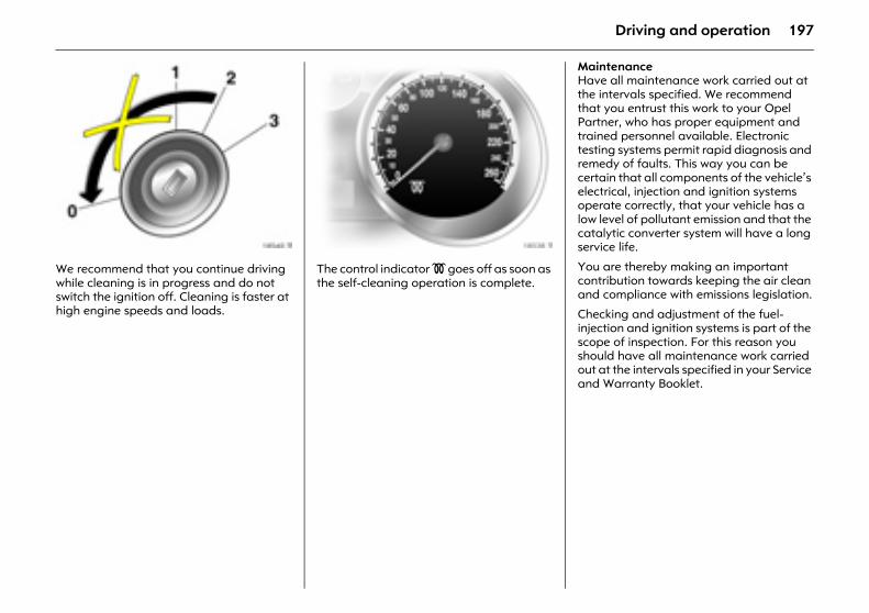
197Driving and operation
Picture no: 18540t.tifWe recommend that you continue driving while cleaning is in progress and do not switch the ignition off. Cleaning is faster at high engine speeds and loads.
Picture no: 18538t.tifThe control indicator ! goes off as soon as the self-cleaning operation is complete.
Maintenance Have all maintenance work carried out at the intervals specified. We recommend that you entrust this work to your Opel Partner, who has proper equipment and trained personnel available. Electronic testing systems permit rapid diagnosis and remedy of faults. This way you can be certain that all components of the vehicle’s electrical, injection and ignition systems operate correctly, that your vehicle has a low level of pollutant emission and that the catalytic converter system will have a long service life.
You are thereby making an important contribution towards keeping the air clean and compliance with emissions legislation.
Checking and adjustment of the fuel-injection and ignition systems is part of the scope of inspection. For this reason you should have all maintenance work carried out at the intervals specified in your Service and Warranty Booklet.
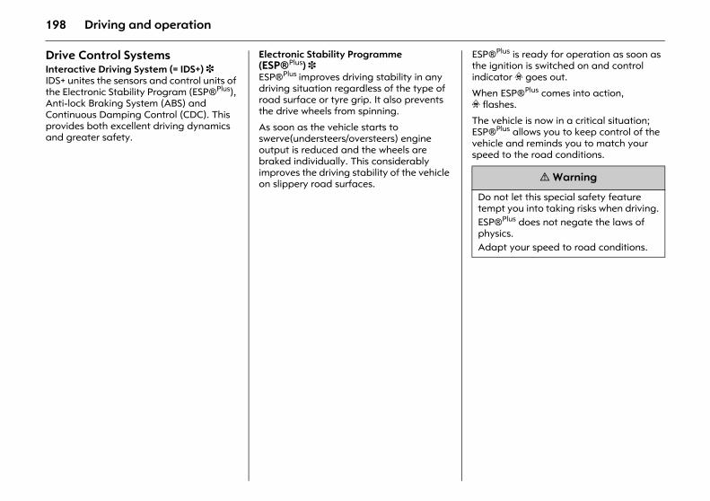
198 Driving and operation
Drive Control SystemsInteractive Driving System (= IDS+) 3 IDS+ unites the sensors and control units of the Electronic Stability Program (ESP®Plus), Anti-lock Braking System (ABS) and Continuous Damping Control (CDC). This provides both excellent driving dynamics and greater safety.
Electronic Stability Programme (ESP®Plus) 3 ESP®Plus improves driving stability in any driving situation regardless of the type of road surface or tyre grip. It also prevents the drive wheels from spinning.
As soon as the vehicle starts to swerve(understeers/oversteers) engine output is reduced and the wheels are braked individually. This considerably improves the driving stability of the vehicle on slippery road surfaces.
ESP®Plus is ready for operation as soon as the ignition is switched on and control indicator v goes out.
When ESP®Plus comes into action, v flashes.
The vehicle is now in a critical situation; ESP®Plus allows you to keep control of the vehicle and reminds you to match your speed to the road conditions.
9 Warning
Do not let this special safety feature tempt you into taking risks when driving.ESP®Plus does not negate the laws of physics. Adapt your speed to road conditions.
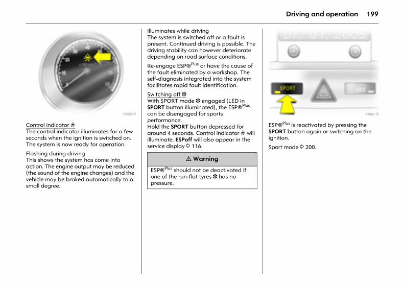
199Driving and operation
Picture no: 17200t.tifControl indicator v The control indicator illuminates for a few seconds when the ignition is switched on. The system is now ready for operation.
Flashing during driving This shows the system has come into action. The engine output may be reduced (the sound of the engine changes) and the vehicle may be braked automatically to a small degree.
Illuminates while driving The system is switched off or a fault is present. Continued driving is possible. The driving stability can however deteriorate depending on road surface conditions.
Re-engage ESP®Plus or have the cause of the fault eliminated by a workshop. The self-diagnosis integrated into the system facilitates rapid fault identification.
Switching off 3 With SPORT mode 3 engaged (LED in SPORT button illuminated), the ESP®Plus can be disengaged for sports performance. Hold the SPORT button depressed for around 4 seconds. Control indicator v will illuminate. ESPoff will also appear in the service display 3 116.
Picture no: 17961t.tifESP®Plus is reactivated by pressing the SPORT button again or switching on the ignition.
Sport mode 3 200.
9 Warning
ESP®Plus should not be deactivated if one of the run-flat tyres 3 has no pressure.
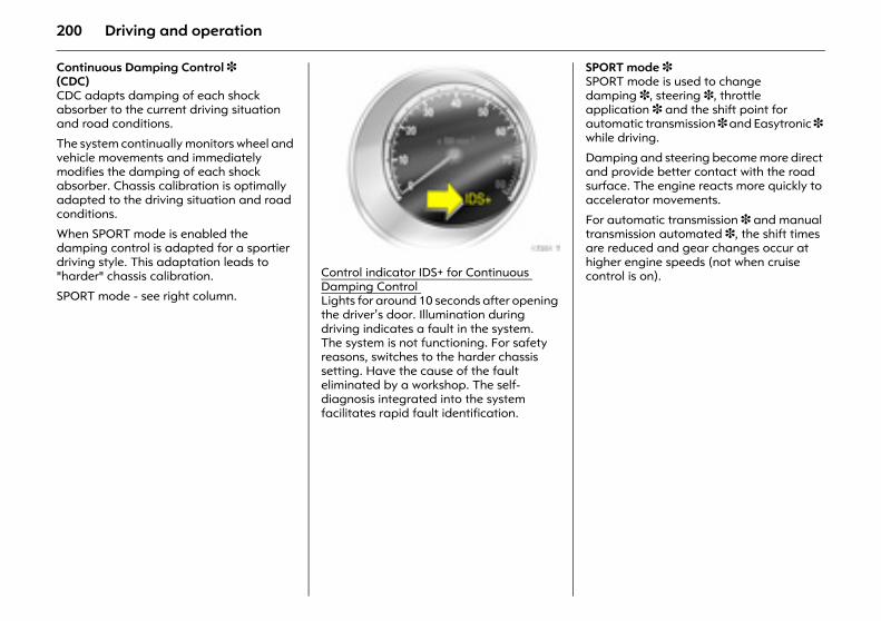
200 Driving and operation
Continuous Damping Control 3 (CDC) CDC adapts damping of each shock absorber to the current driving situation and road conditions.
The system continually monitors wheel and vehicle movements and immediately modifies the damping of each shock absorber. Chassis calibration is optimally adapted to the driving situation and road conditions.
When SPORT mode is enabled the damping control is adapted for a sportier driving style. This adaptation leads to "harder" chassis calibration.
SPORT mode - see right column.
Picture no: 17201t.tifControl indicator IDS+ for Continuous Damping Control Lights for around 10 seconds after opening the driver’s door. Illumination during driving indicates a fault in the system. The system is not functioning. For safety reasons, switches to the harder chassis setting. Have the cause of the fault eliminated by a workshop. The self-diagnosis integrated into the system facilitates rapid fault identification.
SPORT mode 3 SPORT mode is used to change damping 3, steering 3, throttle application 3 and the shift point for automatic transmission 3 and Easytronic 3 while driving.
Damping and steering become more direct and provide better contact with the road surface. The engine reacts more quickly to accelerator movements.
For automatic transmission 3 and manual transmission automated 3, the shift times are reduced and gear changes occur at higher engine speeds (not when cruise control is on).
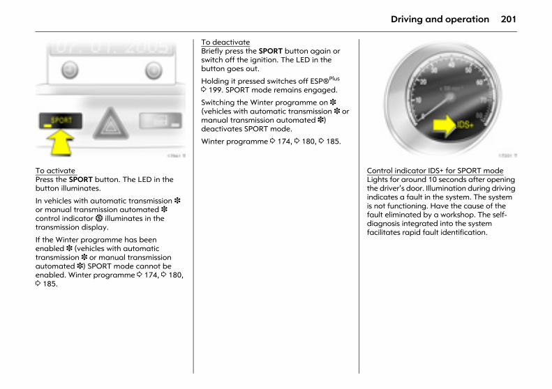
201Driving and operation
Picture no: 17961t.tifTo activate Press the SPORT button. The LED in the button illuminates.
In vehicles with automatic transmission 3 or manual transmission automated 3 control indicator 1 illuminates in the transmission display.
If the Winter programme has been enabled 3 (vehicles with automatic transmission 3 or manual transmission automated 3) SPORT mode cannot be enabled. Winter programme 3 174, 3 180, 3 185.
To deactivateBriefly press the SPORT button again or switch off the ignition. The LED in the button goes out.
Holding it pressed switches off ESP®Plus 3 199. SPORT mode remains engaged.
Switching the Winter programme on 3 (vehicles with automatic transmission 3 or manual transmission automated 3) deactivates SPORT mode.
Winter programme 3 174, 3 180, 3 185.
Picture no: 17201t.tifControl indicator IDS+ for SPORT modeLights for around 10 seconds after opening the driver’s door. Illumination during driving indicates a fault in the system. The system is not functioning. Have the cause of the fault eliminated by a workshop. The self-diagnosis integrated into the system facilitates rapid fault identification.
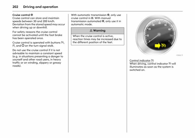
202 Driving and operation
Cruise control 3 Cruise control can store and maintain speeds between 30 and 200 km/h. Deviation from the stored speed may occur when driving up or downhill.
For safety reasons the cruise control cannot be activated until the foot brake has been operated once.
Cruise control is operated with buttons m, g, and § on the turn signal stalk.
Do not use the cruise control if it is not advisable to maintain a constant speed (e.g. in situations presenting a danger to yourself and other road users, in heavy traffic or on winding, slippery or greasy roads).
With automatic transmission 3, only use cruise control in D. With manual transmission automated 3, only use it in automatic mode.
Picture no: 17202t.tifControl indicator m When driving, control indicator m will illuminates as soon as the system is switched on.
9 Warning
When the cruise control is active, reaction times may be increased due to the different position of the feet.
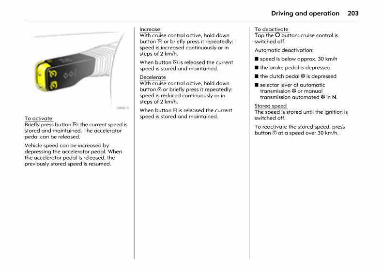
203Driving and operation
Picture no: 16990t.tifTo activate Briefly press button m: the current speed is stored and maintained. The accelerator pedal can be released.
Vehicle speed can be increased by depressing the accelerator pedal. When the accelerator pedal is released, the previously stored speed is resumed.
Increase With cruise control active, hold down button m or briefly press it repeatedly: speed is increased continuously or in steps of 2 km/h.
When button m is released the current speed is stored and maintained.
Decelerate With cruise control active, hold down button g or briefly press it repeatedly: speed is reduced continuously or in steps of 2 km/h.
When button g is released the current speed is stored and maintained.
To deactivate Tap the § button: cruise control is switched off.
Automatic deactivation:
z speed is below approx. 30 km/h
z the brake pedal is depressed
z the clutch pedal 3 is depressed
z selector lever of automatic transmission 3 or manual transmission automated 3 in N.
Stored speed The speed is stored until the ignition is switched off.
To reactivate the stored speed, press button g at a speed over 30 km/h.
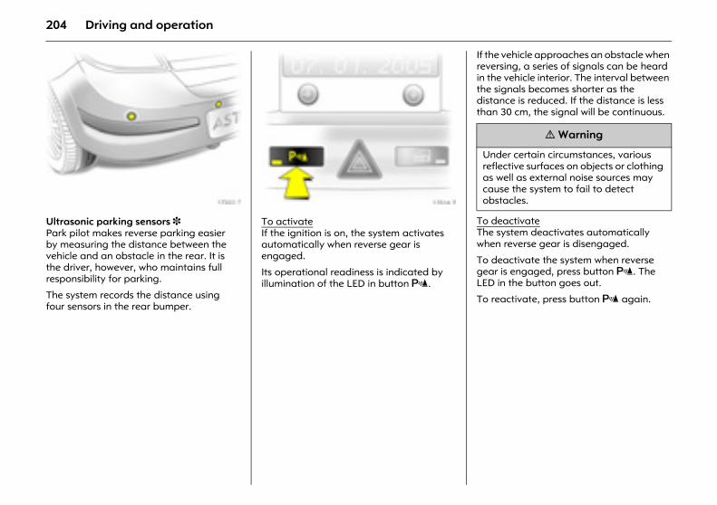
204 Driving and operation
Picture no: 17203t.tifUltrasonic parking sensors 3 Park pilot makes reverse parking easier by measuring the distance between the vehicle and an obstacle in the rear. It is the driver, however, who maintains full responsibility for parking.
The system records the distance using four sensors in the rear bumper.
Picture no: 17016t.tifTo activateIf the ignition is on, the system activates automatically when reverse gear is engaged.
Its operational readiness is indicated by illumination of the LED in button r.
If the vehicle approaches an obstacle when reversing, a series of signals can be heard in the vehicle interior. The interval between the signals becomes shorter as the distance is reduced. If the distance is less than 30 cm, the signal will be continuous.
To deactivateThe system deactivates automatically when reverse gear is disengaged.
To deactivate the system when reverse gear is engaged, press button r. The LED in the button goes out.
To reactivate, press button r again.
9 Warning
Under certain circumstances, various reflective surfaces on objects or clothing as well as external noise sources may cause the system to fail to detect obstacles.
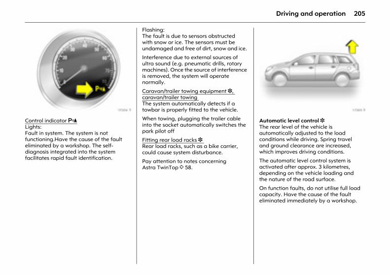
205Driving and operation
Picture no: 17204t.tifControl indicator rLights:Fault in system. The system is not functioning.Have the cause of the fault eliminated by a workshop. The self-diagnosis integrated into the system facilitates rapid fault identification.
Flashing:The fault is due to sensors obstructed with snow or ice. The sensors must be undamaged and free of dirt, snow and ice.
Interference due to external sources of ultra sound (e.g. pneumatic drills, rotary machines). Once the source of interference is removed, the system will operate normally.
Caravan/trailer towing equipment 3, caravan/trailer towing The system automatically detects if a towbar is properly fitted to the vehicle.
When towing, plugging the trailer cable into the socket automatically switches the park pilot off
Fitting rear load racks 3 Rear load racks, such as a bike carrier, could cause system disturbance.
Pay attention to notes concerning Astra TwinTop 3 58.
Picture no: 17205t.tifAutomatic level control 3 The rear level of the vehicle is automatically adjusted to the load conditions while driving. Spring travel and ground clearance are increased, which improves driving conditions.
The automatic level control system is activated after approx. 3 kilometres, depending on the vehicle loading and the nature of the road surface.
On function faults, do not utilise full load capacity. Have the cause of the fault eliminated immediately by a workshop.
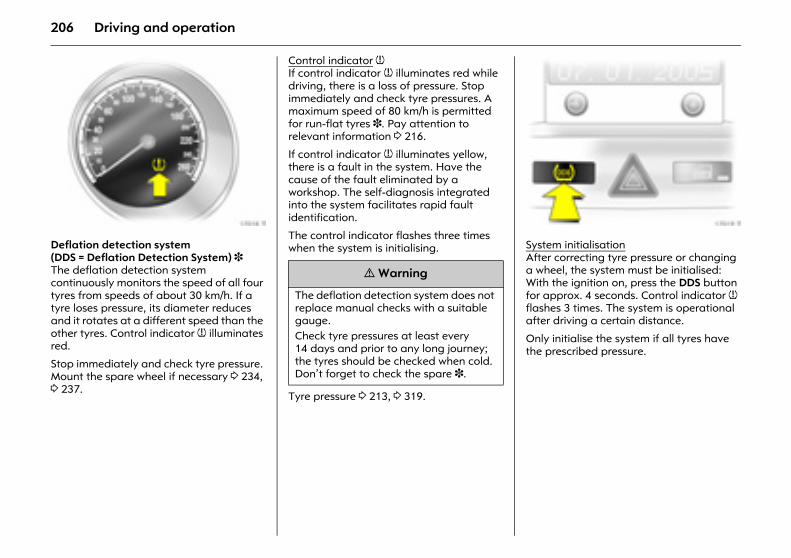
206 Driving and operation
Picture no: 17018t.tifDeflation detection system (DDS = Deflation Detection System) 3 The deflation detection system continuously monitors the speed of all four tyres from speeds of about 30 km/h. If a tyre loses pressure, its diameter reduces and it rotates at a different speed than the other tyres. Control indicator w illuminates red.
Stop immediately and check tyre pressure. Mount the spare wheel if necessary 3 234, 3 237.
Control indicator w If control indicator w illuminates red while driving, there is a loss of pressure. Stop immediately and check tyre pressures. A maximum speed of 80 km/h is permitted for run-flat tyres 3. Pay attention to relevant information 3 216.
If control indicator w illuminates yellow, there is a fault in the system. Have the cause of the fault eliminated by a workshop. The self-diagnosis integrated into the system facilitates rapid fault identification.
The control indicator flashes three times when the system is initialising.
Tyre pressure 3 213, 3 319.
Picture no: 17019t.tifSystem initialisationAfter correcting tyre pressure or changing a wheel, the system must be initialised: With the ignition on, press the DDS button for approx. 4 seconds. Control indicator w flashes 3 times. The system is operational after driving a certain distance.
Only initialise the system if all tyres have the prescribed pressure.
9 Warning
The deflation detection system does not replace manual checks with a suitable gauge. Check tyre pressures at least every 14 days and prior to any long journey; the tyres should be checked when cold. Don’t forget to check the spare 3.
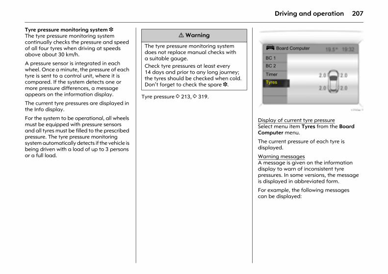
207Driving and operation
Tyre pressure monitoring system 3 The tyre pressure monitoring system continually checks the pressure and speed of all four tyres when driving at speeds above about 30 km/h.
A pressure sensor is integrated in each wheel. Once a minute, the pressure of each tyre is sent to a control unit, where it is compared. If the system detects one or more pressure differences, a message appears on the information display.
The current tyre pressures are displayed in the Info display.
For the system to be operational, all wheels must be equipped with pressure sensors and all tyres must be filled to the prescribed pressure. The tyre pressure monitoring system automatically detects if the vehicle is being driven with a load of up to 3 persons or a full load.
Tyre pressure 3 213, 3 319.
Picture no: 17334t.tifDisplay of current tyre pressureSelect menu item Tyres from the Board Computer menu.
The current pressure of each tyre is displayed.
Warning messagesA message is given on the information display to warn of inconsistent tyre pressures. In some versions, the message is displayed in abbreviated form.
For example, the following messages can be displayed:
9 Warning
The tyre pressure monitoring system does not replace manual checks with a suitable gauge. Check tyre pressures at least every 14 days and prior to any long journey; the tyres should be checked when cold. Don’t forget to check the spare 3.
Ü Board Computer
BC 1
BC 2
Timer
Tyres
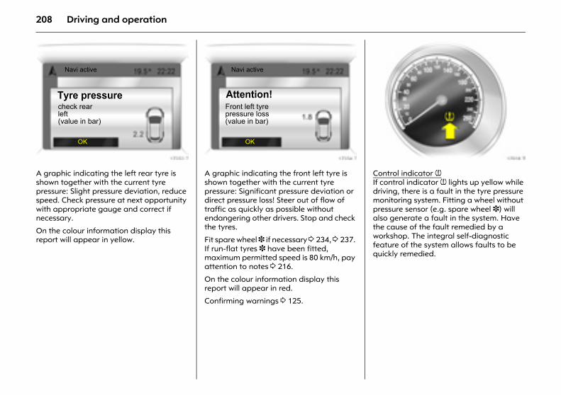
208 Driving and operation
Picture no: 17353t.tifA graphic indicating the left rear tyre is shown together with the current tyre pressure: Slight pressure deviation, reduce speed. Check pressure at next opportunity with appropriate gauge and correct if necessary.
On the colour information display this report will appear in yellow.
Picture no: 17354t.tifA graphic indicating the front left tyre is shown together with the current tyre pressure: Significant pressure deviation or direct pressure loss! Steer out of flow of traffic as quickly as possible without endangering other drivers. Stop and check the tyres.
Fit spare wheel 3 if necessary 3 234, 3 237. If run-flat tyres 3 have been fitted, maximum permitted speed is 80 km/h, pay attention to notes 3 216.
On the colour information display this report will appear in red.
Confirming warnings 3 125.
Picture no: 17018t.tifControl indicator w If control indicator w lights up yellow while driving, there is a fault in the tyre pressure monitoring system. Fitting a wheel without pressure sensor (e.g. spare wheel 3) will also generate a fault in the system. Have the cause of the fault remedied by a workshop. The integral self-diagnostic feature of the system allows faults to be quickly remedied.
Navi active
Tyre pressure
OK
check rearleft(value in bar)
Navi active
Attention!
OK
Front left tyrepressure loss(value in bar)
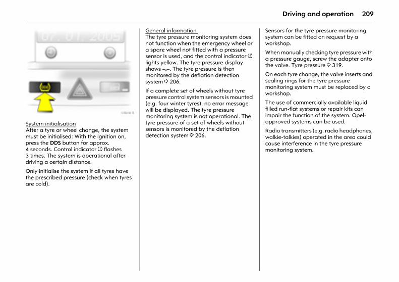
209Driving and operation
Picture no: 17019t.tifSystem initialisationAfter a tyre or wheel change, the system must be initialised: With the ignition on, press the DDS button for approx. 4 seconds. Control indicator w flashes 3 times. The system is operational after driving a certain distance.
Only initialise the system if all tyres have the prescribed pressure (check when tyres are cold).
General information The tyre pressure monitoring system does not function when the emergency wheel or a spare wheel not fitted with a pressure sensor is used, and the control indicator w lights yellow. The tyre pressure display shows –.–. The tyre pressure is then monitored by the deflation detection system 3 206.
If a complete set of wheels without tyre pressure control system sensors is mounted (e.g. four winter tyres), no error message will be displayed. The tyre pressure monitoring system is not operational. The tyre pressure of a set of wheels without sensors is monitored by the deflation detection system 3 206.
Sensors for the tyre pressure monitoring system can be fitted on request by a workshop.
When manually checking tyre pressure with a pressure gauge, screw the adapter onto the valve. Tyre pressure 3 319.
On each tyre change, the valve inserts and sealing rings for the tyre pressure monitoring system must be replaced by a workshop.
The use of commercially available liquid filled run-flat systems or repair kits can impair the function of the system. Opel-approved systems can be used.
Radio transmitters (e.g. radio headphones, walkie-talkies) operated in the area could cause interference in the tyre pressure monitoring system.
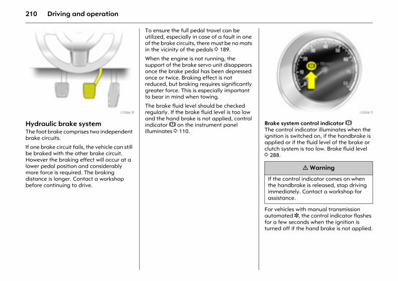
210 Driving and operation
Picture no: 17206t.tifHydraulic brake system The foot brake comprises two independent brake circuits.
If one brake circuit fails, the vehicle can still be braked with the other brake circuit. However the braking effect will occur at a lower pedal position and considerably more force is required. The braking distance is longer. Contact a workshop before continuing to drive.
To ensure the full pedal travel can be utilized, especially in case of a fault in one of the brake circuits, there must be no mats in the vicinity of the pedals 3 189.
When the engine is not running, the support of the brake servo unit disappears once the brake pedal has been depressed once or twice. Braking effect is not reduced, but braking requires significantly greater force. This is especially important to bear in mind when towing.
The brake fluid level should be checked regularly. If the brake fluid level is too low and the hand brake is not applied, control indicator R on the instrument panel illuminates 3 110.
Picture no: 17208t.tifBrake system control indicator R The control indicator illuminates when the ignition is switched on, if the handbrake is applied or if the fluid level of the brake or clutch system is too low. Brake fluid level 3 288.
For vehicles with manual transmission automated 3, the control indicator flashes for a few seconds when the ignition is turned off if the hand brake is not applied.
9 Warning
If the control indicator comes on when the handbrake is released, stop driving immediately. Contact a workshop for assistance.
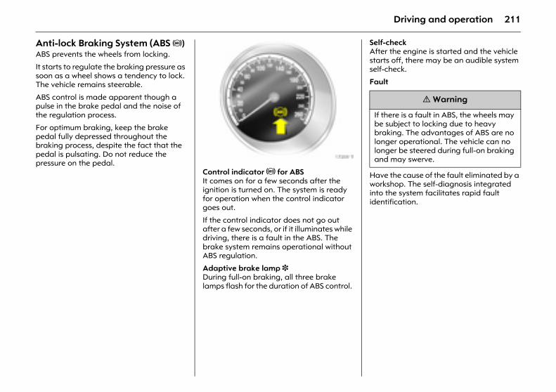
211Driving and operation
Anti-lock Braking System (ABS u) ABS prevents the wheels from locking.
It starts to regulate the braking pressure as soon as a wheel shows a tendency to lock. The vehicle remains steerable.
ABS control is made apparent though a pulse in the brake pedal and the noise of the regulation process.
For optimum braking, keep the brake pedal fully depressed throughout the braking process, despite the fact that the pedal is pulsating. Do not reduce the pressure on the pedal. Picture no: 17209t.tif
Control indicator u for ABS It comes on for a few seconds after the ignition is turned on. The system is ready for operation when the control indicator goes out.
If the control indicator does not go out after a few seconds, or if it illuminates while driving, there is a fault in the ABS. The brake system remains operational without ABS regulation.
Adaptive brake lamp 3 During full-on braking, all three brake lamps flash for the duration of ABS control.
Self-check After the engine is started and the vehicle starts off, there may be an audible system self-check.
Fault
Have the cause of the fault eliminated by a workshop. The self-diagnosis integrated into the system facilitates rapid fault identification.
9 Warning
If there is a fault in ABS, the wheels may be subject to locking due to heavy braking. The advantages of ABS are no longer operational. The vehicle can no longer be steered during full-on braking and may swerve.
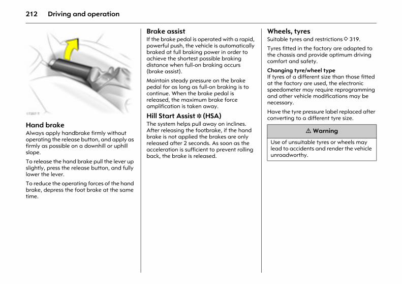
212 Driving and operation
Picture no: 17207t.tifHand brake Always apply handbrake firmly without operating the release button, and apply as firmly as possible on a downhill or uphill slope.
To release the hand brake pull the lever up slightly, press the release button, and fully lower the lever.
To reduce the operating forces of the hand brake, depress the foot brake at the same time.
Brake assist If the brake pedal is operated with a rapid, powerful push, the vehicle is automatically braked at full braking power in order to achieve the shortest possible braking distance when full-on braking occurs (brake assist).
Maintain steady pressure on the brake pedal for as long as full-on braking is to continue. When the brake pedal is released, the maximum brake force amplification is taken away.
Hill Start Assist 3 (HSA) The system helps pull away on inclines. After releasing the footbrake, if the hand brake is not applied the brakes are only released after 2 seconds. As soon as the acceleration is sufficient to prevent rolling back, the brake is released.
Wheels, tyres Suitable tyres and restrictions 3 319.
Tyres fitted in the factory are adapted to the chassis and provide optimum driving comfort and safety.
Changing tyre/wheel type If tyres of a different size than those fitted at the factory are used, the electronic speedometer may require reprogramming and other vehicle modifications may be necessary.
Have the tyre pressure label replaced after converting to a different tyre size.
9 Warning
Use of unsuitable tyres or wheels may lead to accidents and render the vehicle unroadworthy.
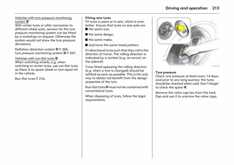
213Driving and operation
Vehicles with tyre pressure monitoring system 3With winter tyres or after conversion to different wheel sizes, sensors for the tyre pressure monitoring system can be fitted by a workshop on request. Otherwise the system would not show the tyre pressure deviations.
Deflation detection system 3 3 206, tyre pressure monitoring system 3 3 207.
Vehicles with run-flat tyres 3 When switching wheels, e.g. when switching to winter tyres, use run-flat tyres as there is no spare wheel or tyre repair kit in the vehicle.
Run-flat tyres 3 216.
Fitting new tyres Fit tyres in pairs or in sets, which is even better. Ensure that tyres on one axle are z the same size,
z the same design,
z the same make,
z and have the same tread pattern.
Fit directional tyres such that they roll in the direction of travel. The rolling direction is indicated by a symbol (e.g. an arrow) on the sidewall.
Tyres fitted opposing the rolling direction (e.g. when a tyre is changed) should be refitted as soon as possible. This is the only way to obtain full benefit from the design properties of the tyre.
Run-flat tyres 3 must not be combined with conventional tyres.
When disposing of tyres, follow the legal requirements.
Picture no: 17211t.tifTyre pressure Check tyre pressure at least every 14 days and prior to any long journey; the tyres should be checked when cold. Don’t forget to check the spare 3.
Remove the valve cap key from the tank flap and use it to unscrew the valve caps.
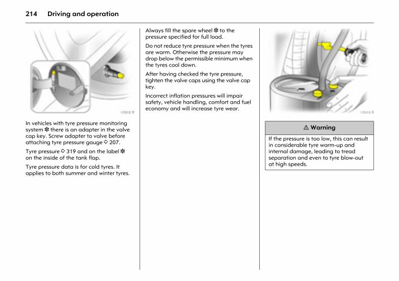
214 Driving and operation
Picture no: 17212t.tifIn vehicles with tyre pressure monitoring system 3 there is an adapter in the valve cap key. Screw adapter to valve before attaching tyre pressure gauge 3 207.
Tyre pressure 3 319 and on the label 3 on the inside of the tank flap.
Tyre pressure data is for cold tyres. It applies to both summer and winter tyres.
Always fill the spare wheel 3 to the pressure specified for full load.
Do not reduce tyre pressure when the tyres are warm. Otherwise the pressure may drop below the permissible minimum when the tyres cool down.
After having checked the tyre pressure, tighten the valve caps using the valve cap key.
Incorrect inflation pressures will impair safety, vehicle handling, comfort and fuel economy and will increase tyre wear.
Picture no: 17213t.tif
9 Warning
If the pressure is too low, this can result in considerable tyre warm-up and internal damage, leading to tread separation and even to tyre blow-out at high speeds.
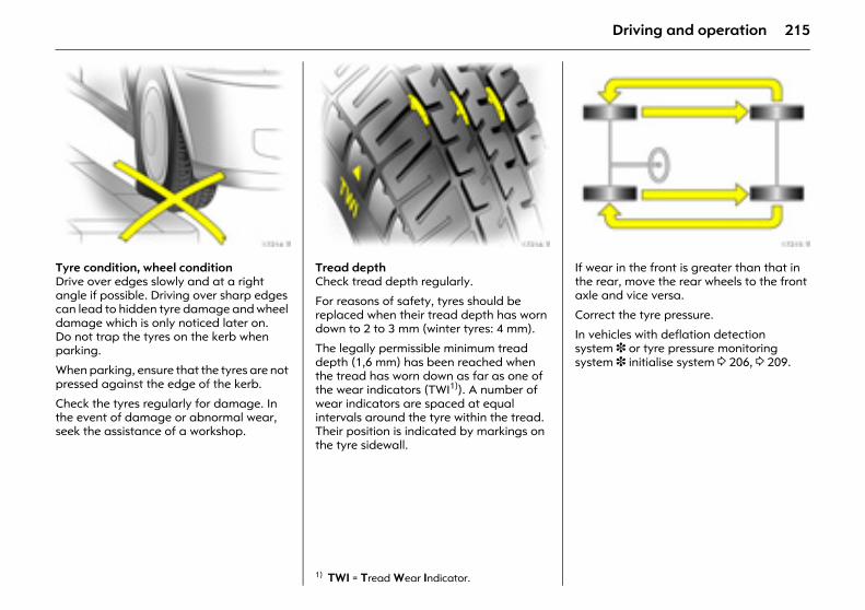
215Driving and operation
Picture no: 17214t.tifTyre condition, wheel condition Drive over edges slowly and at a right angle if possible. Driving over sharp edges can lead to hidden tyre damage and wheel damage which is only noticed later on. Do not trap the tyres on the kerb when parking.
When parking, ensure that the tyres are not pressed against the edge of the kerb.
Check the tyres regularly for damage. In the event of damage or abnormal wear, seek the assistance of a workshop.
Picture no: 17216t.tifTread depth Check tread depth regularly.
For reasons of safety, tyres should be replaced when their tread depth has worn down to 2 to 3 mm (winter tyres: 4 mm).
The legally permissible minimum tread depth (1,6 mm) has been reached when the tread has worn down as far as one of the wear indicators (TWI1)). A number of wear indicators are spaced at equal intervals around the tyre within the tread. Their position is indicated by markings on the tyre sidewall.
Picture no: 17215t.tifIf wear in the front is greater than that in the rear, move the rear wheels to the front axle and vice versa.
Correct the tyre pressure.
In vehicles with deflation detection system 3 or tyre pressure monitoring system 3 initialise system 3 206, 3 209.
1) TWI = Tread Wear Indicator.
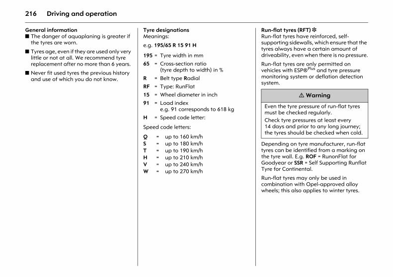
216 Driving and operation
General information z The danger of aquaplaning is greater if
the tyres are worn.
z Tyres age, even if they are used only very little or not at all. We recommend tyre replacement after no more than 6 years.
z Never fit used tyres the previous history and use of which you do not know.
Tyre designations Meanings:
e.g. 195/65 R 15 91 H
Speed code letters:
Run-flat tyres (RFT) 3 Run-flat tyres have reinforced, self-supporting sidewalls, which ensure that the tyres always have a certain amount of driveability, even when there is no pressure.
Run-flat tyres are only permitted on vehicles with ESP®Plus and tyre pressure monitoring system or deflation detection system.
Depending on tyre manufacturer, run-flat tyres can be identified from a marking on the tyre wall. E.g. ROF = RunonFlat for Goodyear or SSR = Self Supporting Runflat Tyre for Continental.
Run-flat tyres may only be used in combination with Opel-approved alloy wheels; this also applies to winter tyres.
195 = Tyre width in mm65 = Cross-section ratio
(tyre depth to width) in %
R = Belt type RadialRF = Type: RunFlat15 = Wheel diameter in inch
91 = Load indexe.g. 91 corresponds to 618 kg
H = Speed code letter:
Q = up to 160 km/hS = up to 180 km/hT = up to 190 km/hH = up to 210 km/hV = up to 240 km/hW = up to 270 km/h
9 Warning
Even the tyre pressure of run-flat tyres must be checked regularly. Check tyre pressures at least every 14 days and prior to any long journey; the tyres should be checked when cold.
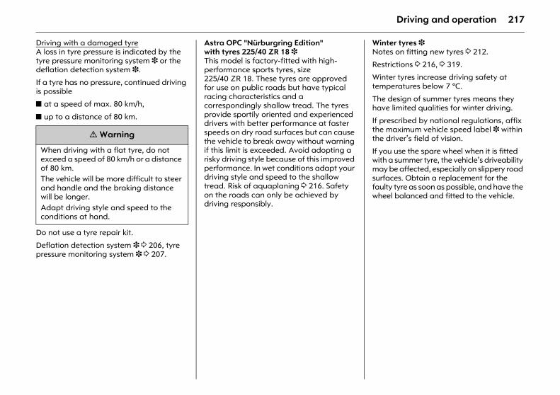
217Driving and operation
Driving with a damaged tyreA loss in tyre pressure is indicated by the tyre pressure monitoring system 3 or the deflation detection system 3.
If a tyre has no pressure, continued driving is possible
z at a speed of max. 80 km/h,
z up to a distance of 80 km.
Do not use a tyre repair kit.
Deflation detection system 3 3 206, tyre pressure monitoring system 3 3 207.
Astra OPC "Nürburgring Edition" with tyres 225/40 ZR 18 3 This model is factory-fitted with high-performance sports tyres, size 225/40 ZR 18. These tyres are approved for use on public roads but have typical racing characteristics and a correspondingly shallow tread. The tyres provide sportily oriented and experienced drivers with better performance at faster speeds on dry road surfaces but can cause the vehicle to break away without warning if this limit is exceeded. Avoid adopting a risky driving style because of this improved performance. In wet conditions adapt your driving style and speed to the shallow tread. Risk of aquaplaning 3 216. Safety on the roads can only be achieved by driving responsibly.
Winter tyres 3 Notes on fitting new tyres 3 212.
Restrictions 3 216, 3 319.
Winter tyres increase driving safety at temperatures below 7 °C.
The design of summer tyres means they have limited qualities for winter driving.
If prescribed by national regulations, affix the maximum vehicle speed label 3 within the driver’s field of vision.
If you use the spare wheel when it is fitted with a summer tyre, the vehicle’s driveability may be affected, especially on slippery road surfaces. Obtain a replacement for the faulty tyre as soon as possible, and have the wheel balanced and fitted to the vehicle.
9 Warning
When driving with a flat tyre, do not exceed a speed of 80 km/h or a distance of 80 km. The vehicle will be more difficult to steer and handle and the braking distance will be longer. Adapt driving style and speed to the conditions at hand.
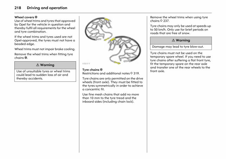
218 Driving and operation
Wheel covers 3 Use of wheel trims and tyres that approved by Opel for the vehicle in question and thereby fulfil all requirements for the wheel and tyre combination.
If the wheel trims and tyres used are not Opel-approved, the tyres must not have a beaded edge.
Wheel trims must not impair brake cooling.
Remove the wheel trims when fitting tyre chains 3.
Picture no: 17217t.tifTyre chains 3 Restrictions and additional notes 3 319.
Tyre chains are only permitted on the drive wheels (front axle). They must be fitted to the tyres symmetrically in order to achieve a concentric fit.
Use fine mesh chains that add no more than 10 mm to the tyre tread and the inboard sides (including chain lock).
Remove the wheel trims when using tyre chains 3 237.
Tyre chains may only be used at speeds up to 50 km/h. Only use for brief periods on roads that are free of snow.
Tyre chains must not be used on the temporary spare wheel. If you need to use tyre chains after suffering a flat front tyre, fit the temporary spare on the rear axle and transfer one of the rear wheels to the front axle.
9 Warning
Use of unsuitable tyres or wheel trims could lead to sudden loss of air and thereby accidents.
9 Warning
Damage may lead to tyre blow-out.
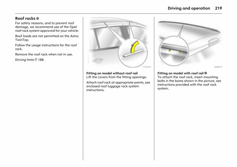
219Driving and operation
Roof racks 3 For safety reasons, and to prevent roof damage, we recommend use of the Opel roof rack system approved for your vehicle.
Roof loads are not permitted on the Astra TwinTop.
Follow the usage instructions for the roof rack.
Remove the roof rack when not in use.
Driving hints 3 188.
Picture no: 17218t.tifFitting on model without roof rail Lift the covers from the fitting openings.
Attach roof rack at appropriate points, see enclosed roof luggage rack system instructions.
Picture no: 18498t.tifFitting on model with roof rail 3 To attach the roof rack, insert mounting bolts in the bores shown in the picture, see instructions provided with the roof rack system.
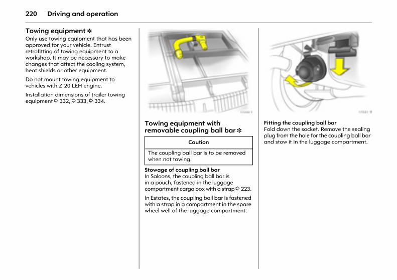
220 Driving and operation
Towing equipment 3 Only use towing equipment that has been approved for your vehicle. Entrust retrofitting of towing equipment to a workshop. It may be necessary to make changes that affect the cooling system, heat shields or other equipment.
Do not mount towing equipment to vehicles with Z 20 LEH engine.
Installation dimensions of trailer towing equipment 3 332, 3 333, 3 334.
Picture no: 17220t.tifTowing equipment with removable coupling ball bar 3
Stowage of coupling ball bar In Saloons, the coupling ball bar is in a pouch, fastened in the luggage compartment cargo box with a strap 3 223.
In Estates, the coupling ball bar is fastened with a strap in a compartment in the spare wheel well of the luggage compartment.
Picture no: 17221t.tifFitting the coupling ball bar Fold down the socket. Remove the sealing plug from the hole for the coupling ball bar and stow it in the luggage compartment. Caution
The coupling ball bar is to be removed when not towing.
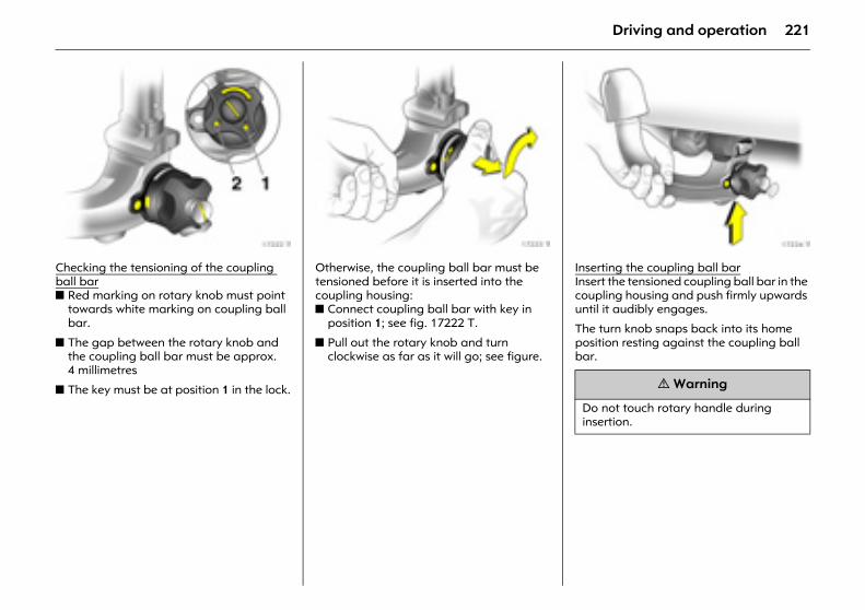
221Driving and operation
Picture no: 17222t.tifChecking the tensioning of the coupling ball barz Red marking on rotary knob must point
towards white marking on coupling ball bar.
z The gap between the rotary knob and the coupling ball bar must be approx. 4 millimetres
z The key must be at position 1 in the lock.
Picture no: 17223t.tifOtherwise, the coupling ball bar must be tensioned before it is inserted into the coupling housing: z Connect coupling ball bar with key in
position 1; see fig. 17222 T.
z Pull out the rotary knob and turn clockwise as far as it will go; see figure.
Picture no: 17224t.tifInserting the coupling ball bar Insert the tensioned coupling ball bar in the coupling housing and push firmly upwards until it audibly engages.
The turn knob snaps back into its home position resting against the coupling ball bar.
9 Warning
Do not touch rotary handle during insertion.
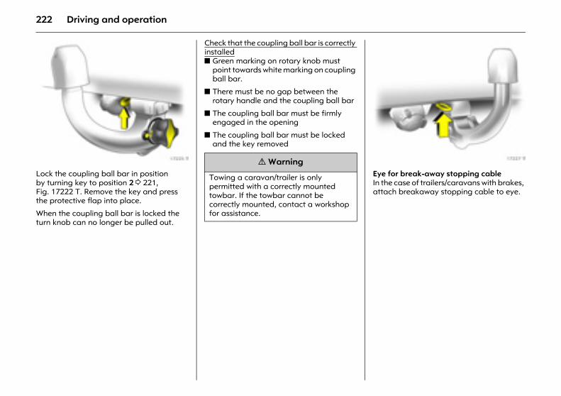
222 Driving and operation
Picture no: 17225t.tifLock the coupling ball bar in position by turning key to position 2 3 221, Fig. 17222 T. Remove the key and press the protective flap into place.
When the coupling ball bar is locked the turn knob can no longer be pulled out.
Check that the coupling ball bar is correctly installedz Green marking on rotary knob must
point towards white marking on coupling ball bar.
z There must be no gap between the rotary handle and the coupling ball bar
z The coupling ball bar must be firmly engaged in the opening
z The coupling ball bar must be locked and the key removed
Picture no: 17227t.tifEye for break-away stopping cable In the case of trailers/caravans with brakes, attach breakaway stopping cable to eye.
9 Warning
Towing a caravan/trailer is only permitted with a correctly mounted towbar. If the towbar cannot be correctly mounted, contact a workshop for assistance.
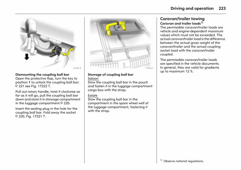
223Driving and operation
Picture no: 17226t.tifDismounting the coupling ball bar Open the protective flap, turn the key to position 1 to unlock the coupling ball bar; 3 221 see Fig. 17222 T.
Pull out rotary handle, twist it clockwise as far as it will go, pull the coupling ball bar down and store it in stowage compartment in the luggage compartment 3 220.
Insert the sealing plug in the hole for the coupling ball bar. Fold away the socket 3 220, Fig. 17221 T.
Picture no: 17220t.tifStowage of coupling ball bar Saloon Stow the coupling ball bar in the pouch and fasten it in the luggage compartment cargo box with the strap.
Estate Stow the coupling ball bar in the compartment in the spare wheel well of the luggage compartment, fastening it with the strap.
Caravan/trailer towingCaravan and trailer loads1)
The permissible caravan/trailer loads are vehicle and engine-dependent maximum values which must not be exceeded. The actual caravan/trailer load is the difference between the actual gross weight of the caravan/trailer and the actual coupling socket load with the caravan/trailer coupled.
The permissible caravan/trailer loads are specified in the vehicle documents. In general, they are valid for gradients up to maximum 12 %.
1) Observe national regulations.
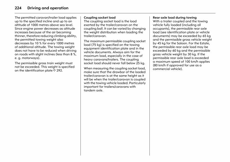
224 Driving and operation
The permitted caravan/trailer load applies up to the specified incline and up to an altitude of 1000 metres above sea level. Since engine power decreases as altitude increases because of the air becoming thinner, therefore reducing climbing ability, the permitted towing weight also decreases by 10 % for every 1000 metres of additional altitude. The towing weight does not have to be reduced when driving on roads with slight inclines (less than 8 %, e. g. motorways).
The permissible gross train weight must not be exceeded. This weight is specified on the identification plate 3 292.
Coupling socket load The coupling socket load is the load exerted by the trailer/caravan on the coupling ball. It can be varied by changing the weight distribution when loading the trailer/caravan.
The maximum permissible coupling socket load (75 kg) is specified on the towing equipment identification plate and in the vehicle documents. Always aim for the maximum load, especially in the case of heavy caravans/trailers. The coupling socket load should never fall below 25 kg.
When measuring the coupling socket load, make sure that the drawbar of the loaded trailer/caravan is at the same height as it will be when the trailer/caravan is coupled with the towing vehicle loaded. Particularly important for trailers/caravans with tandem axle.
Rear axle load during towing With a trailer coupled and the towing vehicle fully loaded (including all occupants), the permissible rear axle load (see identification plate or vehicle documents) may be exceeded by 65 kg and the permissible gross vehicle weight by 45 kg for the Saloon. For the Estate, the permissible rear axle load may be exceeded by 60 kg and the permissible gross vehicle weight by 30 kg. If the permissible rear axle load is exceeded a maximum speed of 100 km/h applies (80 km/h if approved for use as a commercial vehicle).
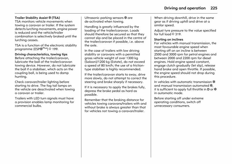
225Driving and operation
Trailer Stability Assist 3 (TSA) TSA monitors vehicle movements when towing a caravan or trailer. If the system detects lurching movements, engine power is reduced and the vehicle/trailer combination is selectively braked until the lurching ceases.
TSA is a function of the electronic stability programme (ESP®Plus) 3 199.
Driving characteristics, towing tips Before attaching the trailer/caravan, lubricate the ball of the trailer/caravan towing device. However, do not lubricate the ball if a stabiliser, which acts on the coupling ball, is being used to damp hunting.
Check caravan/trailer lighting before starting to drive. The fog tail lamps on the vehicle are deactivated when towing a caravan or trailer.
Trailers with LED turn signals must have a provision enables lamp monitoring for commercial bulbs.
Ultrasonic parking sensors 3 are de-activated when towing.
Handling is greatly influenced by the loading of the trailer/caravan. Loads should therefore be secured so that they cannot slip and be placed in the centre of the trailer/caravan if possible, i.e. above the axle.
In the case of trailers with low driving stability or caravans with a permitted gross vehicle weight of over 1300 kg (Saloon)/1200 kg (Estate), do not exceed a speed of 80 km/h; the use of a friction-type stabiliser is highly recommended.
If the trailer/caravan starts to sway, drive more slowly, do not attempt to correct the steering and brake sharply if necessary.
If it is necessary to apply the brakes fully, depress the brake pedal as hard as possible.
Remember that the braking distance for vehicles towing caravans/trailers with and without brake is always greater than that for vehicles not towing a caravan/trailer.
When driving downhill, drive in the same gear as if driving uphill and drive at a similar speed.
Adjust tyre pressure to the value specified for full load 3 319.
Starting on inclines For vehicles with manual transmission, the most favourable engine speed when starting off on an incline is between 2500 and 3000 rpm for petrol engines and between 2000 and 2200 rpm for diesel engines. Hold engine speed constant, engage clutch gradually (let slip), release hand brake and open throttle. If possible, the engine speed should not drop during this procedure.
In vehicles with automatic transmission 3 and manual transmission automated 3, it is sufficient to apply full throttle in D or 3 in automatic mode.
Before starting off under extreme operating conditions, switch off unnecessary consumers.
226 Self-help, vehicle care
Self-help, vehicle care Diesel fuel system, bleeding The diesel fuel system must be bled if the tank was run dry. Turn on the ignition three times for 15 seconds each time. Then start the engine for a maximum of 40 seconds1). Wait at least 5 seconds before repeating the process. If the engine still does not start, seek the assistance of a workshop.
Picture no: 17053t.tifBonnet Pull the release lever on the driver’s side below the instrument panel. Then return the lever to its original position.
Diesel fuel system, bleeding ............... 226 Bonnet .................................................. 226 Starting the engine with jump leads 3 227 Towing.................................................. 229 Warning triangle ¨ 3......................... 232 First-aid kit (cushion) + 3 ................... 232 Spare wheel 3 ...................................... 234 Jack £ 3 and vehicle tools 3 ............ 236 Changing wheels ................................. 237 Tyre repair kit 3 ................................... 240 Electrical system .................................. 244 Fuses and the most important circuits
they protect ....................................... 246 Bulb replacement ................................ 253 Halogen headlamp system ................ 253 Xenon headlamp system 3,
Adaptive Forward Lighting system 3 ............................................ 257
Front indicator lamps.......................... 259 Side turn signal lamps......................... 260 Fog lamps 3......................................... 260 Tail lamps............................................. 260 Number plate lamp............................. 269 Courtesy lamps .................................... 270 Vehicle care.......................................... 271
1) Only possible for 30 seconds with engines A 17 DTJ, A 17 DTR, Z 17 DTH, Z17 DTJ and Z 17 DTR for technical reasons.
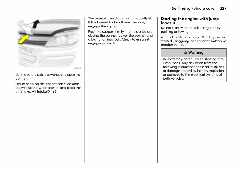
227Self-help, vehicle care
Picture no: 17054t.tifLift the safety catch upwards and open the bonnet.
Dirt or snow on the bonnet can slide onto the windscreen when opened and block the air intake. Air intake 3 169.
The bonnet is held open automatically 3. If the bonnet is of a different version, engage the support.
Push the support firmly into holder before closing the bonnet. Lower the bonnet and allow to fall into lock. Check to ensure it engages properly.
Starting the engine with jump leads 3Do not start with a quick charger or by pushing or towing.
A vehicle with a discharged battery can be started using jump leads and the battery of another vehicle.
9 Warning
Be extremely careful when starting with jump leads. Any deviation from the following instructions can lead to injuries or damage caused by battery explosion or damage to the electrical systems of both vehicles.
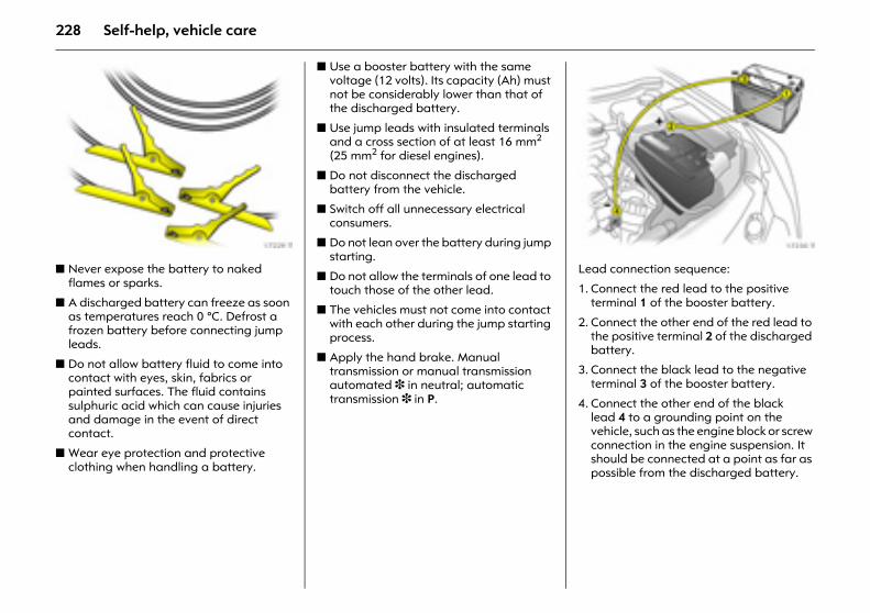
228 Self-help, vehicle care
Picture no: 17229t.tifz Never expose the battery to naked
flames or sparks.
z A discharged battery can freeze as soon as temperatures reach 0 °C. Defrost a frozen battery before connecting jump leads.
z Do not allow battery fluid to come into contact with eyes, skin, fabrics or painted surfaces. The fluid contains sulphuric acid which can cause injuries and damage in the event of direct contact.
z Wear eye protection and protective clothing when handling a battery.
z Use a booster battery with the same voltage (12 volts). Its capacity (Ah) must not be considerably lower than that of the discharged battery.
z Use jump leads with insulated terminals and a cross section of at least 16 mm2 (25 mm2 for diesel engines).
z Do not disconnect the discharged battery from the vehicle.
z Switch off all unnecessary electrical consumers.
z Do not lean over the battery during jump starting.
z Do not allow the terminals of one lead to touch those of the other lead.
z The vehicles must not come into contact with each other during the jump starting process.
z Apply the hand brake. Manual transmission or manual transmission automated 3 in neutral; automatic transmission 3 in P.
Picture no: 17230t.tifLead connection sequence:
1. Connect the red lead to the positive terminal 1 of the booster battery.
2. Connect the other end of the red lead to the positive terminal 2 of the discharged battery.
3. Connect the black lead to the negative terminal 3 of the booster battery.
4. Connect the other end of the black lead 4 to a grounding point on the vehicle, such as the engine block or screw connection in the engine suspension. It should be connected at a point as far as possible from the discharged battery.
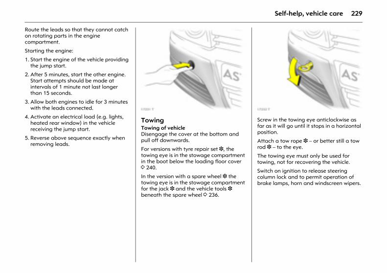
229Self-help, vehicle care
Route the leads so that they cannot catch on rotating parts in the engine compartment.
Starting the engine:
1. Start the engine of the vehicle providing the jump start.
2. After 5 minutes, start the other engine. Start attempts should be made at intervals of 1 minute not last longer than 15 seconds.
3. Allow both engines to idle for 3 minutes with the leads connected.
4. Activate an electrical load (e.g. lights, heated rear window) in the vehicle receiving the jump start.
5. Reverse above sequence exactly when removing leads.
Picture no: 17231t.tifTowing Towing of vehicleDisengage the cover at the bottom and pull off downwards.
For versions with tyre repair set 3, the towing eye is in the stowage compartment in the boot below the loading floor cover 3 240.
In the version with a spare wheel 3 the towing eye is in the stowage compartment for the jack 3 and the vehicle tools 3 beneath the spare wheel 3 236.
Picture no: 17232t.tifScrew in the towing eye anticlockwise as far as it will go until it stops in a horizontal position.
Attach a tow rope 3 – or better still a tow rod 3 – to the eye.
The towing eye must only be used for towing, not for recovering the vehicle.
Switch on ignition to release steering column lock and to permit operation of brake lamps, horn and windscreen wipers.
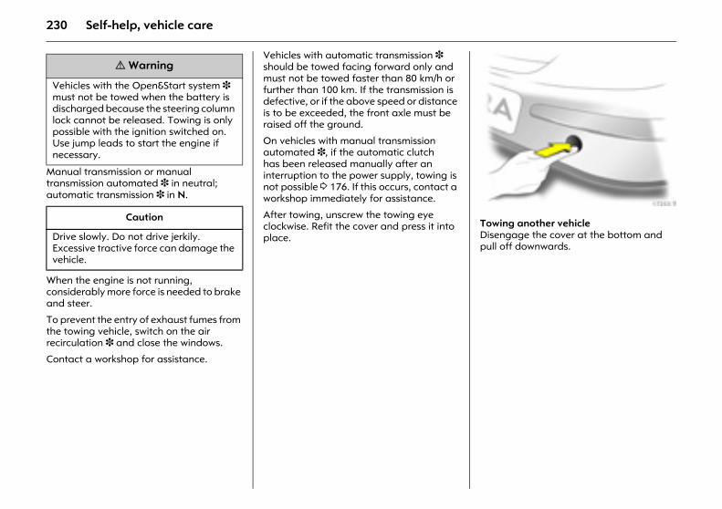
230 Self-help, vehicle care
Manual transmission or manual transmission automated 3 in neutral; automatic transmission 3 in N.
When the engine is not running, considerably more force is needed to brake and steer.
To prevent the entry of exhaust fumes from the towing vehicle, switch on the air recirculation 3 and close the windows.
Contact a workshop for assistance.
Vehicles with automatic transmission 3 should be towed facing forward only and must not be towed faster than 80 km/h or further than 100 km. If the transmission is defective, or if the above speed or distance is to be exceeded, the front axle must be raised off the ground.
On vehicles with manual transmission automated 3, if the automatic clutch has been released manually after an interruption to the power supply, towing is not possible 3 176. If this occurs, contact a workshop immediately for assistance.
After towing, unscrew the towing eye clockwise. Refit the cover and press it into place.
Picture no: 17233t.tifTowing another vehicle Disengage the cover at the bottom and pull off downwards.
9 Warning
Vehicles with the Open&Start system 3 must not be towed when the battery is discharged because the steering column lock cannot be released. Towing is only possible with the ignition switched on. Use jump leads to start the engine if necessary.
Caution
Drive slowly. Do not drive jerkily. Excessive tractive force can damage the vehicle.
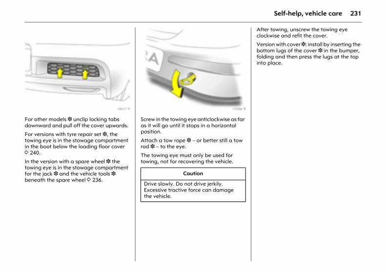
231Self-help, vehicle care
Picture no: 18017t.tifFor other models 3 unclip locking tabs downward and pull off the cover upwards.
For versions with tyre repair set 3, the towing eye is in the stowage compartment in the boot below the loading floor cover 3 240.
In the version with a spare wheel 3 the towing eye is in the stowage compartment for the jack 3 and the vehicle tools 3 beneath the spare wheel 3 236.
Picture no: 17234t.tifScrew in the towing eye anticlockwise as far as it will go until it stops in a horizontal position.
Attach a tow rope 3 – or better still a tow rod 3 – to the eye.
The towing eye must only be used for towing, not for recovering the vehicle.
After towing, unscrew the towing eye clockwise and refit the cover.
Version with cover 3: install by inserting the bottom lugs of the cover 3 in the bumper, folding and then press the lugs at the top into place.
Caution
Drive slowly. Do not drive jerkily. Excessive tractive force can damage the vehicle.
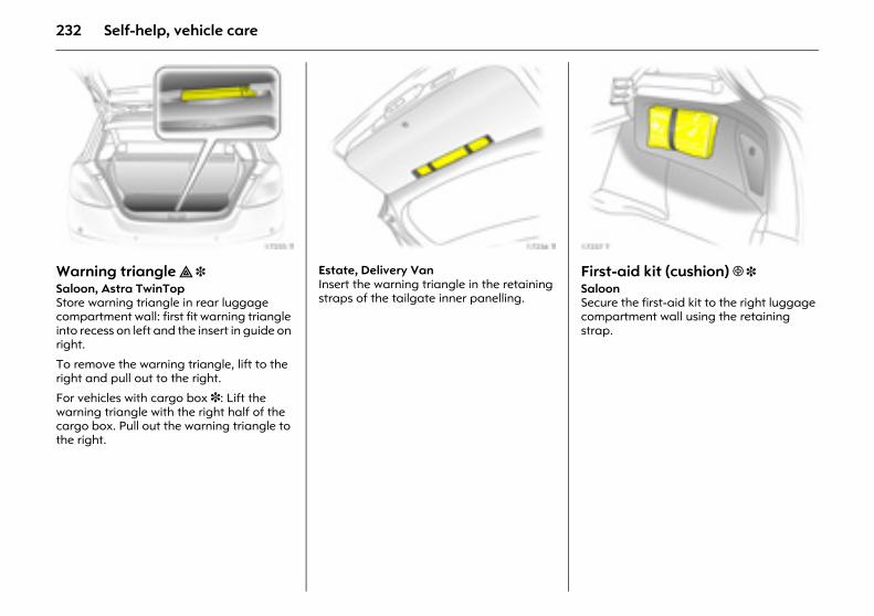
232 Self-help, vehicle care
Picture no: 17235t.tifWarning triangle ¨ 3 Saloon, Astra TwinTop Store warning triangle in rear luggage compartment wall: first fit warning triangle into recess on left and the insert in guide on right.
To remove the warning triangle, lift to the right and pull out to the right.
For vehicles with cargo box 3: Lift the warning triangle with the right half of the cargo box. Pull out the warning triangle to the right.
Picture no: 17236t.tifEstate, Delivery Van Insert the warning triangle in the retaining straps of the tailgate inner panelling.
Picture no: 17237t.tifFirst-aid kit (cushion) + 3 Saloon Secure the first-aid kit to the right luggage compartment wall using the retaining strap.
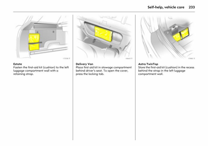
233Self-help, vehicle care
Picture no: 17238t.tifEstate Fasten the first-aid kit (cushion) to the left luggage compartment wall with a retaining strap.
Picture no: 18443t.tifDelivery Van Place first aid kit in stowage compartment behind driver’s seat. To open the cover, press the locking tab.
Picture no: 17985t.tifAstra TwinTop Store the first-aid kit (cushion) in the recess behind the strap in the left luggage compartment wall.
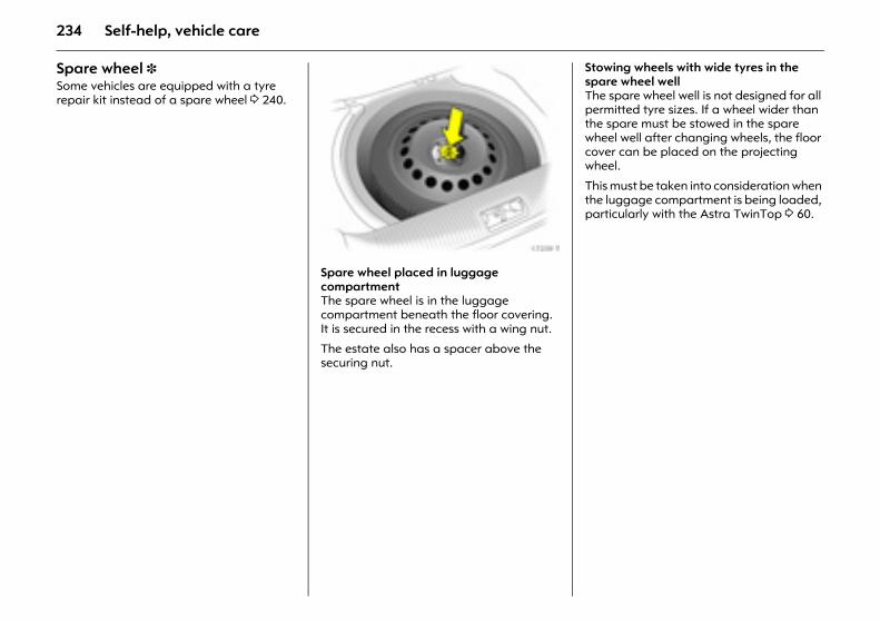
234 Self-help, vehicle care
Spare wheel 3 Some vehicles are equipped with a tyre repair kit instead of a spare wheel 3 240.
Picture no: 17239t.tifSpare wheel placed in luggage compartment The spare wheel is in the luggage compartment beneath the floor covering. It is secured in the recess with a wing nut.
The estate also has a spacer above the securing nut.
Stowing wheels with wide tyres in the spare wheel well The spare wheel well is not designed for all permitted tyre sizes. If a wheel wider than the spare must be stowed in the spare wheel well after changing wheels, the floor cover can be placed on the projecting wheel.
This must be taken into consideration when the luggage compartment is being loaded, particularly with the Astra TwinTop 3 60.
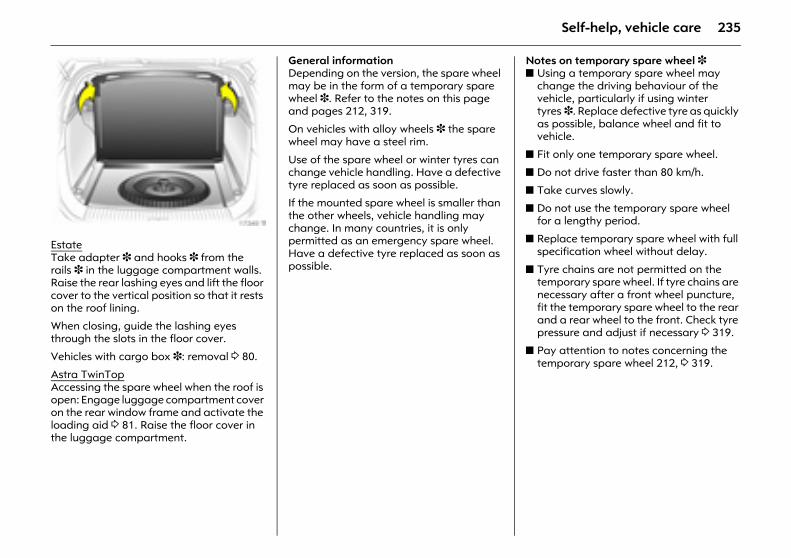
235Self-help, vehicle care
Picture no: 17240t.tifEstateTake adapter 3 and hooks 3 from the rails 3 in the luggage compartment walls. Raise the rear lashing eyes and lift the floor cover to the vertical position so that it rests on the roof lining.
When closing, guide the lashing eyes through the slots in the floor cover.
Vehicles with cargo box 3: removal 3 80.
Astra TwinTopAccessing the spare wheel when the roof is open: Engage luggage compartment cover on the rear window frame and activate the loading aid 3 81. Raise the floor cover in the luggage compartment.
General information Depending on the version, the spare wheel may be in the form of a temporary spare wheel 3. Refer to the notes on this page and pages 212, 319.
On vehicles with alloy wheels 3 the spare wheel may have a steel rim.
Use of the spare wheel or winter tyres can change vehicle handling. Have a defective tyre replaced as soon as possible.
If the mounted spare wheel is smaller than the other wheels, vehicle handling may change. In many countries, it is only permitted as an emergency spare wheel. Have a defective tyre replaced as soon as possible.
Notes on temporary spare wheel 3 z Using a temporary spare wheel may
change the driving behaviour of the vehicle, particularly if using winter tyres 3. Replace defective tyre as quickly as possible, balance wheel and fit to vehicle.
z Fit only one temporary spare wheel.
z Do not drive faster than 80 km/h.
z Take curves slowly.
z Do not use the temporary spare wheel for a lengthy period.
z Replace temporary spare wheel with full specification wheel without delay.
z Tyre chains are not permitted on the temporary spare wheel. If tyre chains are necessary after a front wheel puncture, fit the temporary spare wheel to the rear and a rear wheel to the front. Check tyre pressure and adjust if necessary 3 319.
z Pay attention to notes concerning the temporary spare wheel 212, 3 319.
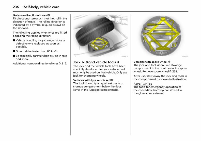
236 Self-help, vehicle care
Notes on directional tyres 3 Fit directional tyres such that they roll in the direction of travel. The rolling direction is indicated by a symbol (e.g. an arrow) on the sidewall.
The following applies when tyres are fitted opposing the rolling direction:
z Vehicle handling may change. Have a defective tyre replaced as soon as possible.
z Do not drive faster than 80 km/h.
z Be especially careful when driving in rain and snow.
Additional notes on directional tyres 3 212.
Picture no: 17241t.tifJack £ 3 and vehicle tools 3 The jack and the vehicle tools have been specially developed for your vehicle and must only be used on that vehicle. Only use jack for changing wheels.
Vehicles with tyre repair set 3 The tool kit and tyre repair set are in a storage compartment below the floor cover in the luggage compartment.
Picture no: 17242t.tifVehicles with spare wheel 3 The jack and tool kit are in a stowage compartment in the boot below the spare wheel. Remove spare wheel 3 234.
After use, stow away the jack and tools in the compartment as shown in illustration.
Astra TwinTopThe tools for emergency operation of the convertible hardtop are stowed in the glove compartment.
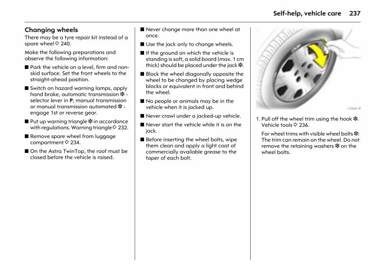
237Self-help, vehicle care
Changing wheels There may be a tyre repair kit instead of a spare wheel 3 240.
Make the following preparations and observe the following information:
z Park the vehicle on a level, firm and non-skid surface. Set the front wheels to the straight-ahead position.
z Switch on hazard warning lamps, apply hand brake, automatic transmission 3 - selector lever in P; manual transmission or manual transmission automated 3 - engage 1st or reverse gear.
z Put up warning triangle 3 in accordance with regulations. Warning triangle 3 232.
z Remove spare wheel from luggage compartment 3 234.
z On the Astra TwinTop, the roof must be closed before the vehicle is raised.
z Never change more than one wheel at once.
z Use the jack only to change wheels.
z If the ground on which the vehicle is standing is soft, a solid board (max. 1 cm thick) should be placed under the jack 3.
z Block the wheel diagonally opposite the wheel to be changed by placing wedge blocks or equivalent in front and behind the wheel.
z No people or animals may be in the vehicle when it is jacked up.
z Never crawl under a jacked-up vehicle.
z Never start the vehicle while it is on the jack.
z Before inserting the wheel bolts, wipe them clean and apply a light coat of commercially available grease to the taper of each bolt.
Picture no: 17243t.tif1. Pull off the wheel trim using the hook 3.
Vehicle tools 3 236.
For wheel trims with visible wheel bolts 3: The trim can remain on the wheel. Do not remove the retaining washers 3 on the wheel bolts.
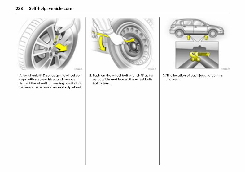
238 Self-help, vehicle care
Picture no: 17244t.tifAlloy wheels 3: Disengage the wheel bolt caps with a screwdriver and remove. Protect the wheel by inserting a soft cloth between the screwdriver and ally wheel.
Picture no: 17245t.tif2. Push on the wheel bolt wrench 3 as far
as possible and loosen the wheel bolts half a turn.
Picture no: 17246t.tif3. The location of each jacking point is
marked.
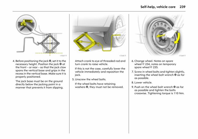
239Self-help, vehicle care
Picture no: 17247t.tif4. Before positioning the jack 3, set it to the
necessary height. Position the jack 3 at the front – or rear – so that the jack claw spans the vertical base and grips in the recess in the vertical base. Make sure it is properly positioned.
The jack base must be on the ground directly below the jacking point in a manner that prevents it from slipping.
Picture no: 17248t.tifAttach crank to eye of threaded rod and turn crank to raise vehicle.
If this is not the case, carefully lower the vehicle immediately and reposition the jack.
5. Unscrew the wheel bolts.
If the wheel bolts have retaining washers 3, they must not be removed.
Picture no: 17249t.tif6. Change wheel. Notes on spare
wheel 3 234, notes on temporary spare wheel 3 235.
7. Screw in wheel bolts and tighten slightly, inserting the wheel bolt wrench 3 as far as possible.
8. Lower vehicle.
9. Push on the wheel bolt wrench 3 as far as possible and tighten the bolts crosswise. Tightening torque is 110 Nm.
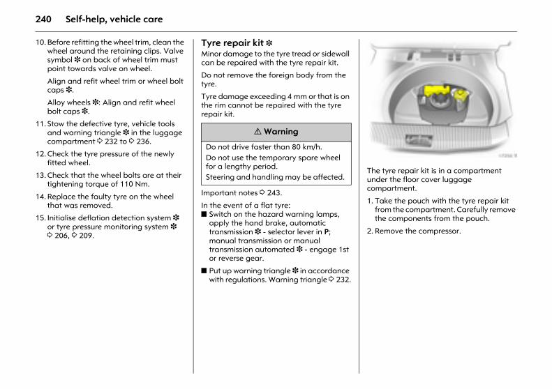
240 Self-help, vehicle care
10. Before refitting the wheel trim, clean the wheel around the retaining clips. Valve symbol 3 on back of wheel trim must point towards valve on wheel.
Align and refit wheel trim or wheel bolt caps 3.
Alloy wheels 3: Align and refit wheel bolt caps 3.
11. Stow the defective tyre, vehicle tools and warning triangle 3 in the luggage compartment 3 232 to 3 236.
12. Check the tyre pressure of the newly fitted wheel.
13. Check that the wheel bolts are at their tightening torque of 110 Nm.
14. Replace the faulty tyre on the wheel that was removed.
15. Initialise deflation detection system 3 or tyre pressure monitoring system 3 3 206, 3 209.
Tyre repair kit 3 Minor damage to the tyre tread or sidewall can be repaired with the tyre repair kit.
Do not remove the foreign body from the tyre.
Tyre damage exceeding 4 mm or that is on the rim cannot be repaired with the tyre repair kit.
Important notes 3 243.
In the event of a flat tyre: z Switch on the hazard warning lamps,
apply the hand brake, automatic transmission 3 - selector lever in P; manual transmission or manual transmission automated 3 - engage 1st or reverse gear.
z Put up warning triangle 3 in accordance with regulations. Warning triangle 3 232.
Picture no: 17250t.tifThe tyre repair kit is in a compartment under the floor cover luggage compartment.
1. Take the pouch with the tyre repair kit from the compartment. Carefully remove the components from the pouch.
2. Remove the compressor.
9 Warning
Do not drive faster than 80 km/h. Do not use the temporary spare wheel for a lengthy period. Steering and handling may be affected.
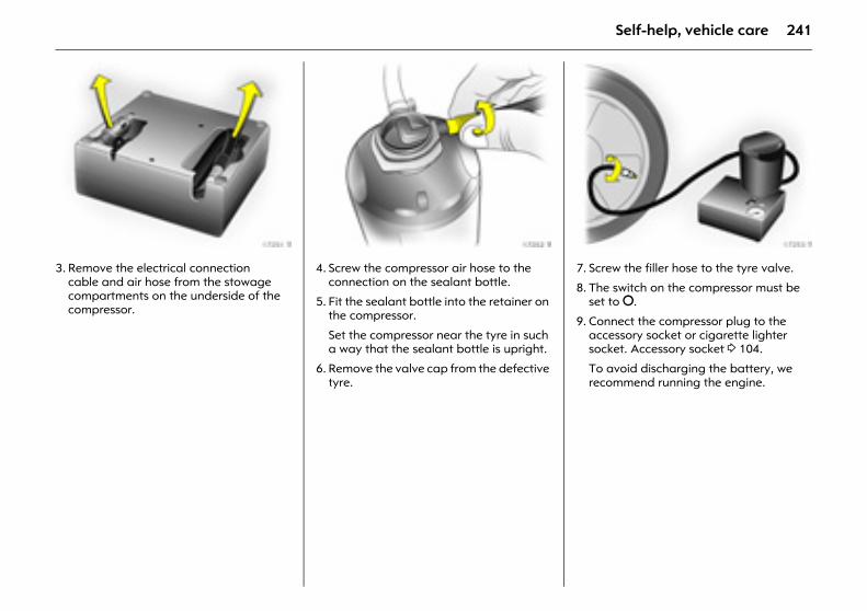
241Self-help, vehicle care
Picture no: 17251t.tif3. Remove the electrical connection
cable and air hose from the stowage compartments on the underside of the compressor.
Picture no: 17252t.tif4. Screw the compressor air hose to the
connection on the sealant bottle.
5. Fit the sealant bottle into the retainer on the compressor.
Set the compressor near the tyre in such a way that the sealant bottle is upright.
6. Remove the valve cap from the defective tyre.
Picture no: 17253t.tif7. Screw the filler hose to the tyre valve.
8. The switch on the compressor must be set to §.
9. Connect the compressor plug to the accessory socket or cigarette lighter socket. Accessory socket 3 104.
To avoid discharging the battery, we recommend running the engine.
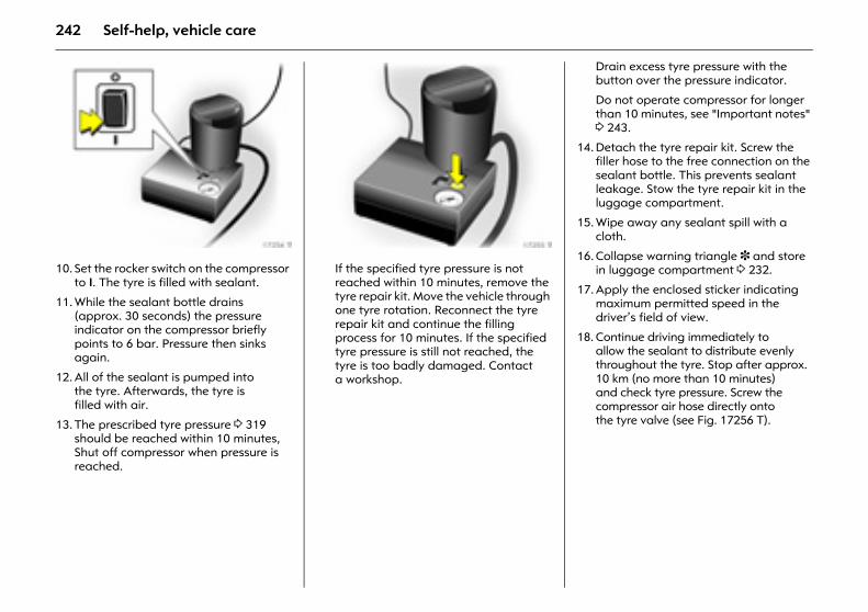
242 Self-help, vehicle care
Picture no: 17254t.tif10. Set the rocker switch on the compressor
to I. The tyre is filled with sealant.
11. While the sealant bottle drains (approx. 30 seconds) the pressure indicator on the compressor briefly points to 6 bar. Pressure then sinks again.
12. All of the sealant is pumped into the tyre. Afterwards, the tyre is filled with air.
13. The prescribed tyre pressure 3 319 should be reached within 10 minutes, Shut off compressor when pressure is reached.
Picture no: 17255t.tifIf the specified tyre pressure is not reached within 10 minutes, remove the tyre repair kit. Move the vehicle through one tyre rotation. Reconnect the tyre repair kit and continue the filling process for 10 minutes. If the specified tyre pressure is still not reached, the tyre is too badly damaged. Contact a workshop.
Drain excess tyre pressure with the button over the pressure indicator.
Do not operate compressor for longer than 10 minutes, see "Important notes" 3 243.
14. Detach the tyre repair kit. Screw the filler hose to the free connection on the sealant bottle. This prevents sealant leakage. Stow the tyre repair kit in the luggage compartment.
15. Wipe away any sealant spill with a cloth.
16. Collapse warning triangle 3 and store in luggage compartment 3 232.
17. Apply the enclosed sticker indicating maximum permitted speed in the driver’s field of view.
18. Continue driving immediately to allow the sealant to distribute evenly throughout the tyre. Stop after approx. 10 km (no more than 10 minutes) and check tyre pressure. Screw the compressor air hose directly onto the tyre valve (see Fig. 17256 T).
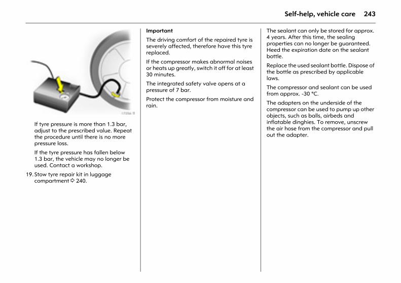
243Self-help, vehicle care
Picture no: 17256t.tifIf tyre pressure is more than 1.3 bar, adjust to the prescribed value. Repeat the procedure until there is no more pressure loss.
If the tyre pressure has fallen below 1.3 bar, the vehicle may no longer be used. Contact a workshop.
19. Stow tyre repair kit in luggage compartment 3 240.
Important
The driving comfort of the repaired tyre is severely affected, therefore have this tyre replaced.
If the compressor makes abnormal noises or heats up greatly, switch it off for at least 30 minutes.
The integrated safety valve opens at a pressure of 7 bar.
Protect the compressor from moisture and rain.
The sealant can only be stored for approx. 4 years. After this time, the sealing properties can no longer be guaranteed. Heed the expiration date on the sealant bottle.
Replace the used sealant bottle. Dispose of the bottle as prescribed by applicable laws.
The compressor and sealant can be used from approx. -30 °C.
The adapters on the underside of the compressor can be used to pump up other objects, such as balls, airbeds and inflatable dinghies. To remove, unscrew the air hose from the compressor and pull out the adapter.
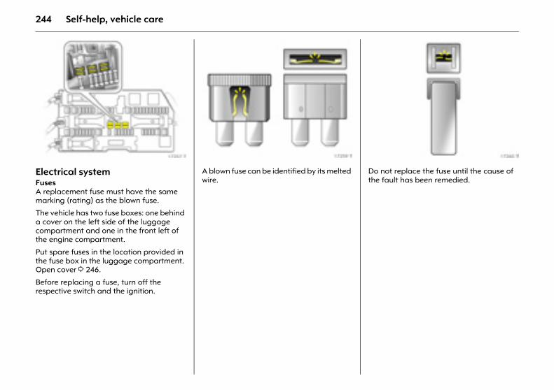
244 Self-help, vehicle care
Picture no: 17257t.tifElectrical system Fuses A replacement fuse must have the same marking (rating) as the blown fuse.
The vehicle has two fuse boxes: one behind a cover on the left side of the luggage compartment and one in the front left of the engine compartment.
Put spare fuses in the location provided in the fuse box in the luggage compartment. Open cover 3 246.
Before replacing a fuse, turn off the respective switch and the ignition.
Picture no: 17259t.tifA blown fuse can be identified by its melted wire.
Picture no: 17260t.tifDo not replace the fuse until the cause of the fault has been remedied.
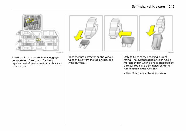
245Self-help, vehicle care
Picture no: 17258t.tifThere is a fuse extractor in the luggage compartment fuse box to facilitate replacement of fuses - see figure above for an example.
Picture no: 18449t.tifPlace the fuse extractor on the various types of fuse from the top or side, and withdraw fuse.
Picture no: Only fit fuses of the specified current rating. The current rating of each fuse is marked on it in writing and is indicated by a colour code. It is also indicated at the fuse location in the fuse box.
Different versions of fuses are used.
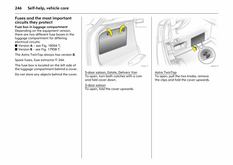
246 Self-help, vehicle care
Fuses and the most important circuits they protectFuse box in luggage compartmentDepending on the equipment version, there are two different fuse boxes in the luggage compartment for differing electrical circuits: z Version A – see Fig. 18504 T, z Version B – see Fig. 17958 T.
The Astra TwinTop always has version B.
Spare fuses, fuse extractor 3 244.
The fuse box is located on the left side of the luggage compartment behind a cover.
Do not store any objects behind the cover.
Picture no: 17261t.tif5-door saloon, Estate, Delivery VanTo open, turn both catches with a coin and fold cover down.
3-door saloonTo open, fold the cover upwards.
Picture no: 18022t.tifAstra TwinTop To open, pull the two knobs, remove the clips and fold the cover upwards.
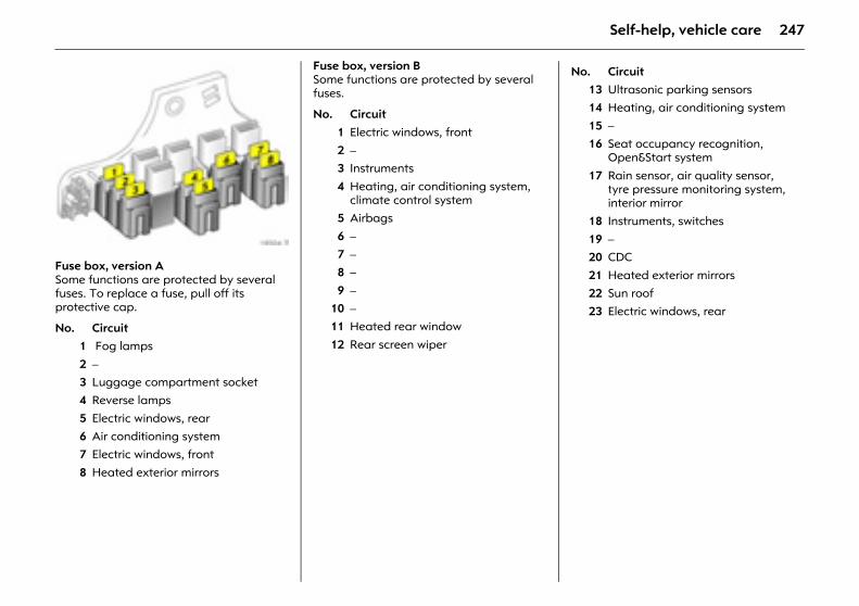
247Self-help, vehicle care
Picture no: 18504t.tifFuse box, version ASome functions are protected by several fuses. To replace a fuse, pull off its protective cap.
Fuse box, version BSome functions are protected by several fuses.
No. Circuit1 Fog lamps
2 – 3 Luggage compartment socket4 Reverse lamps
5 Electric windows, rear6 Air conditioning system7 Electric windows, front
8 Heated exterior mirrors
No. Circuit1 Electric windows, front2 –3 Instruments
4 Heating, air conditioning system, climate control system
5 Airbags
6 –7 –8 –
9 –10 –11 Heated rear window
12 Rear screen wiper
No. Circuit13 Ultrasonic parking sensors14 Heating, air conditioning system
15 –16 Seat occupancy recognition,
Open&Start system
17 Rain sensor, air quality sensor, tyre pressure monitoring system, interior mirror
18 Instruments, switches 19 –20 CDC
21 Heated exterior mirrors 22 Sun roof 23 Electric windows, rear
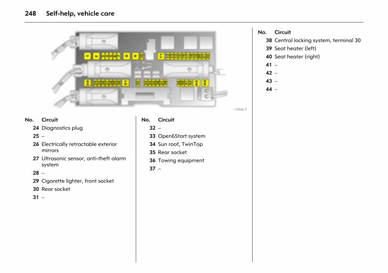
248 Self-help, vehicle care
Picture no: 17958t.tif Picture no: No. Circuit
24 Diagnostics plug 25 –26 Electrically retractable exterior
mirrors27 Ultrasonic sensor, anti-theft alarm
system
28 –29 Cigarette lighter, front socket30 Rear socket
31 –
No. Circuit32 –33 Open&Start system 34 Sun roof, TwinTop
35 Rear socket 36 Towing equipment37 –
No. Circuit38 Central locking system, terminal 3039 Seat heater (left)
40 Seat heater (right)41 –42 –
43 –44 –
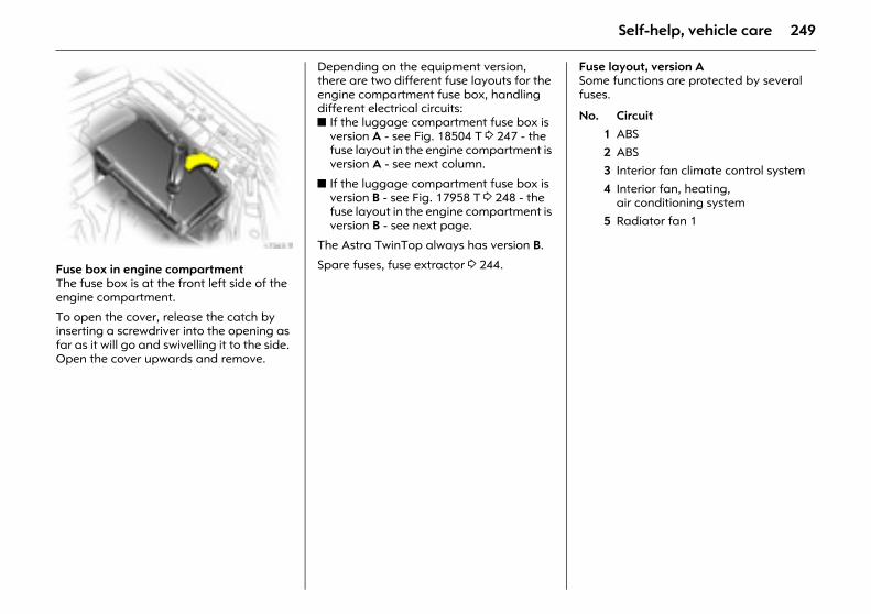
249Self-help, vehicle care
Picture no: 17263t.tifFuse box in engine compartment The fuse box is at the front left side of the engine compartment.
To open the cover, release the catch by inserting a screwdriver into the opening as far as it will go and swivelling it to the side. Open the cover upwards and remove.
Depending on the equipment version, there are two different fuse layouts for the engine compartment fuse box, handling different electrical circuits: z If the luggage compartment fuse box is
version A - see Fig. 18504 T 3 247 - the fuse layout in the engine compartment is version A - see next column.
z If the luggage compartment fuse box is version B - see Fig. 17958 T 3 248 - the fuse layout in the engine compartment is version B - see next page.
The Astra TwinTop always has version B.
Spare fuses, fuse extractor 3 244.
Fuse layout, version ASome functions are protected by several fuses.
No. Circuit1 ABS2 ABS3 Interior fan climate control system
4 Interior fan, heating, air conditioning system
5 Radiator fan 1

250 Self-help, vehicle care
Picture no: 17264t.tif Picture no: No. Circuit
6 Radiator fan 27 Central locking system 8 Windscreen washer system,
tailgate9 Heated rear window, heated
exterior mirrors
10 Diagnostics plug11 Instruments12 Mobile telephone, digital radio,
Twin Audio, display13 Courtesy lamp
No. Circuit14 Windscreen wipers 15 Windscreen wipers16 Horn, ABS, brake lamp switch,
air conditioning system17 Diesel filter or air conditioning
system
18 Starter19 –20 Horn
No. Circuit21 Engine electronics22 Engine electronics
23 Headlamp range adjustment 24 Fuel pump25 –
26 Engine electronics27 Heating, air conditioning system,
air quality sensor
28 –29 Power steering30 Engine electronics
31 Rear screen wiper32 Brake lamp switch33 Headlamp range adjustment, light
switch, clutch switch, instrument assembly, driver’s door module
34 Control unit, steering column module
35 Infotainment system36 Cigarette lighter, front socket
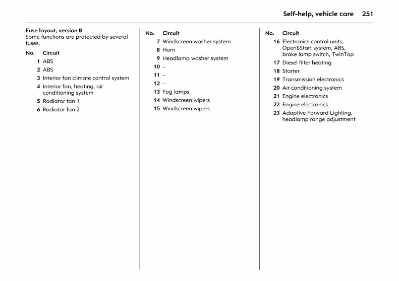
251Self-help, vehicle care
Fuse layout, version BSome functions are protected by several fuses.
No. Circuit1 ABS2 ABS3 Interior fan climate control system
4 Interior fan, heating, air conditioning system
5 Radiator fan 1
6 Radiator fan 2
No. Circuit7 Windscreen washer system8 Horn
9 Headlamp washer system10 –11 –
12 –13 Fog lamps14 Windscreen wipers
15 Windscreen wipers
No. Circuit16 Electronics control units,
Open&Start system, ABS, brake lamp switch, TwinTop
17 Diesel filter heating18 Starter
19 Transmission electronics20 Air conditioning system21 Engine electronics
22 Engine electronics23 Adaptive Forward Lighting,
headlamp range adjustment
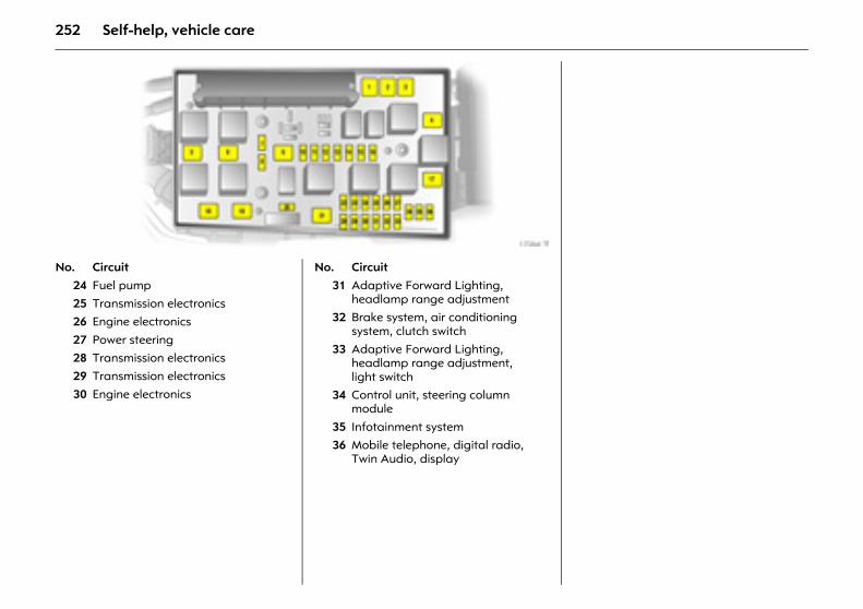
252 Self-help, vehicle care
Picture no: 17264t.tif Picture no: No. Circuit
24 Fuel pump25 Transmission electronics26 Engine electronics
27 Power steering28 Transmission electronics29 Transmission electronics
30 Engine electronics
No. Circuit31 Adaptive Forward Lighting,
headlamp range adjustment32 Brake system, air conditioning
system, clutch switch33 Adaptive Forward Lighting,
headlamp range adjustment, light switch
34 Control unit, steering column module
35 Infotainment system36 Mobile telephone, digital radio,
Twin Audio, display
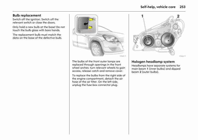
253Self-help, vehicle care
Bulb replacement Switch off the ignition. Switch off the relevant switch or close the doors.
Only hold a new bulb at the base! Do not touch the bulb glass with bare hands.
The replacement bulb must match the data on the base of the defective bulb.
Picture no: 17265t.tifThe bulbs of the front outer lamps are replaced through openings in the front wheel arches: turn relevant wheels to gain access, release catch and remove cover.
To replace the bulbs from the right side of the engine compartment, detach the air hose of the air filter. On the left side, unplug the fuse box connector plug.
Picture no: 17266t.tifHalogen headlamp system Headlamps have separate systems for main beam 1 (inner bulbs) and dipped beam 2 (outer bulbs).
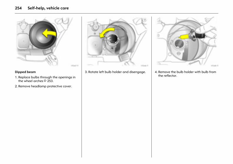
254 Self-help, vehicle care
Picture no: 17267t.tifDipped beam
1. Replace bulbs through the openings in the wheel arches 3 253.
2. Remove headlamp protective cover.
Picture no: 17268t.tif3. Rotate left bulb holder and disengage.
Picture no: 17269t.tif4. Remove the bulb holder with bulb from
the reflector.
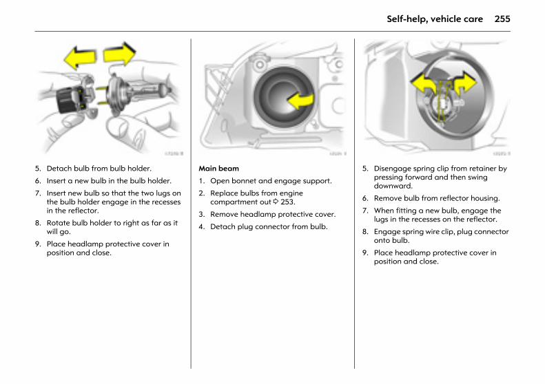
255Self-help, vehicle care
Picture no: 17270t.tif5. Detach bulb from bulb holder.
6. Insert a new bulb in the bulb holder.
7. Insert new bulb so that the two lugs on the bulb holder engage in the recesses in the reflector.
8. Rotate bulb holder to right as far as it will go.
9. Place headlamp protective cover in position and close.
Picture no: 17271t.tifMain beam
1. Open bonnet and engage support.
2. Replace bulbs from engine compartment out 3 253.
3. Remove headlamp protective cover.
4. Detach plug connector from bulb.
Picture no: 17272t.tif5. Disengage spring clip from retainer by
pressing forward and then swing downward.
6. Remove bulb from reflector housing.
7. When fitting a new bulb, engage the lugs in the recesses on the reflector.
8. Engage spring wire clip, plug connector onto bulb.
9. Place headlamp protective cover in position and close.
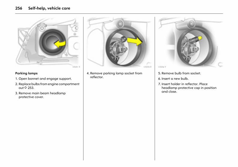
256 Self-help, vehicle care
Picture no: 17271t.tifParking lamps
1. Open bonnet and engage support.
2. Replace bulbs from engine compartment out 3 253.
3. Remove main beam headlamp protective cover.
Picture no: 17273t.tif4. Remove parking lamp socket from
reflector.
Picture no: 17274t.tif5. Remove bulb from socket.
6. Insert a new bulb.
7. Insert holder in reflector. Place headlamp protective cap in position and close.
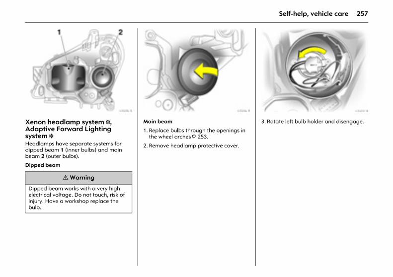
257Self-help, vehicle care
Picture no: 17275t.tifXenon headlamp system 3, Adaptive Forward Lighting system 3 Headlamps have separate systems for dipped beam 1 (inner bulbs) and main beam 2 (outer bulbs).
Dipped beam
Picture no: 17276t.tifMain beam
1. Replace bulbs through the openings in the wheel arches 3 253.
2. Remove headlamp protective cover.
Picture no: 17277t.tif3. Rotate left bulb holder and disengage.
9 Warning
Dipped beam works with a very high electrical voltage. Do not touch, risk of injury. Have a workshop replace the bulb.
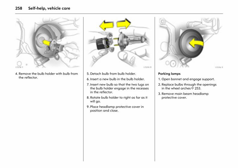
258 Self-help, vehicle care
Picture no: 17278t.tif4. Remove the bulb holder with bulb from
the reflector.
Picture no: 17270t.tif5. Detach bulb from bulb holder.
6. Insert a new bulb in the bulb holder.
7. Insert new bulb so that the two lugs on the bulb holder engage in the recesses in the reflector.
8. Rotate bulb holder to right as far as it will go.
9. Place headlamp protective cover in position and close.
Picture no: 17276t.tifParking lamps
1. Open bonnet and engage support.
2. Replace bulbs through the openings in the wheel arches 3 253.
3. Remove main beam headlamp protective cover.
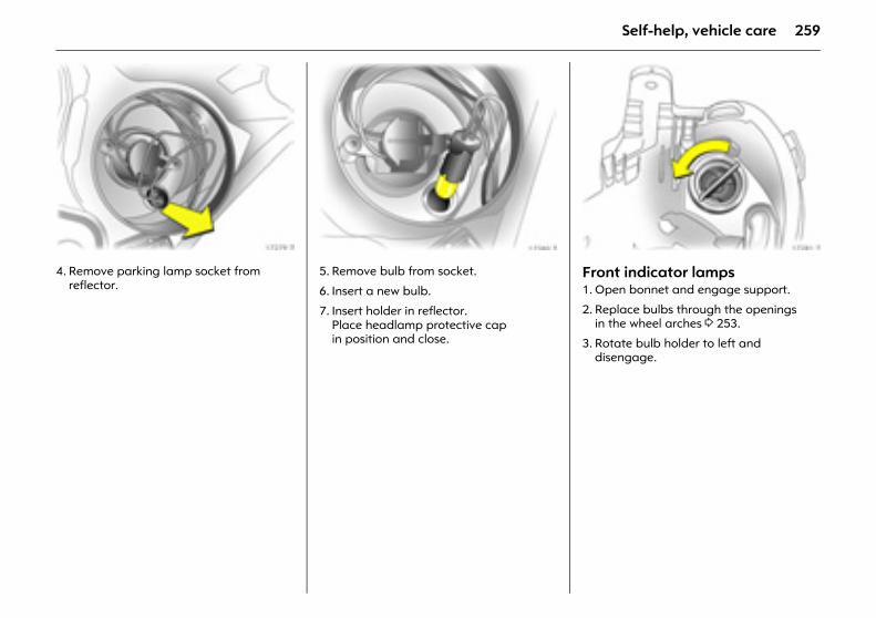
259Self-help, vehicle care
Picture no: 17279t.tif4. Remove parking lamp socket from
reflector.
Picture no: 17280t.tif5. Remove bulb from socket.
6. Insert a new bulb.
7. Insert holder in reflector. Place headlamp protective cap in position and close.
Picture no: 17281t.tifFront indicator lamps 1. Open bonnet and engage support.
2. Replace bulbs through the openings in the wheel arches 3 253.
3. Rotate bulb holder to left and disengage.
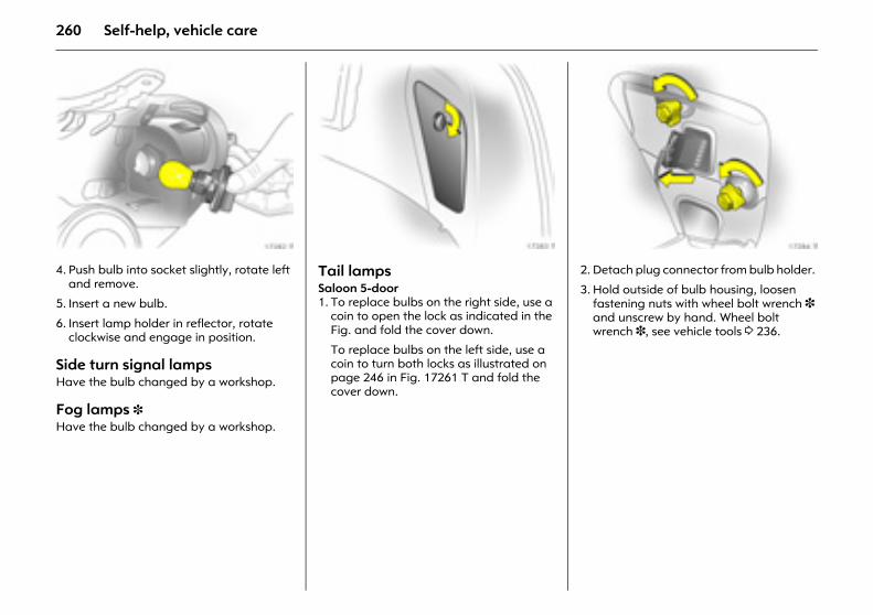
260 Self-help, vehicle care
Picture no: 17282t.tif4. Push bulb into socket slightly, rotate left
and remove.
5. Insert a new bulb.
6. Insert lamp holder in reflector, rotate clockwise and engage in position.
Side turn signal lamps Have the bulb changed by a workshop.
Fog lamps 3 Have the bulb changed by a workshop.
Picture no: 17283t.tifTail lamps Saloon 5-door 1. To replace bulbs on the right side, use a
coin to open the lock as indicated in the Fig. and fold the cover down.
To replace bulbs on the left side, use a coin to turn both locks as illustrated on page 246 in Fig. 17261 T and fold the cover down.
Picture no: 17284t.tif2. Detach plug connector from bulb holder.
3. Hold outside of bulb housing, loosen fastening nuts with wheel bolt wrench 3 and unscrew by hand. Wheel bolt wrench 3, see vehicle tools 3 236.
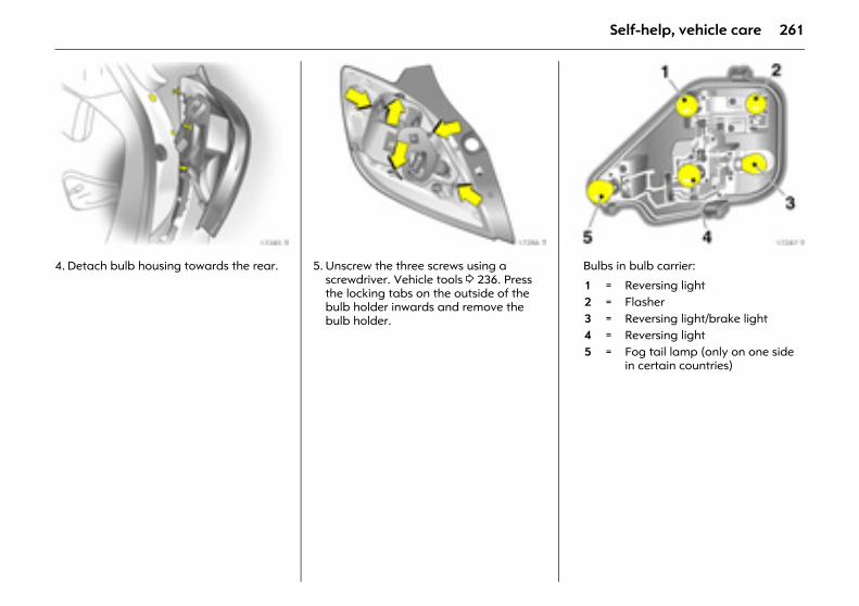
261Self-help, vehicle care
Picture no: 17285t.tif4. Detach bulb housing towards the rear.
Picture no: 17286t.tif5. Unscrew the three screws using a
screwdriver. Vehicle tools 3 236. Press the locking tabs on the outside of the bulb holder inwards and remove the bulb holder.
Picture no: 17287t.tifBulbs in bulb carrier:
1 = Reversing light2 = Flasher3 = Reversing light/brake light4 = Reversing light5 = Fog tail lamp (only on one side
in certain countries)
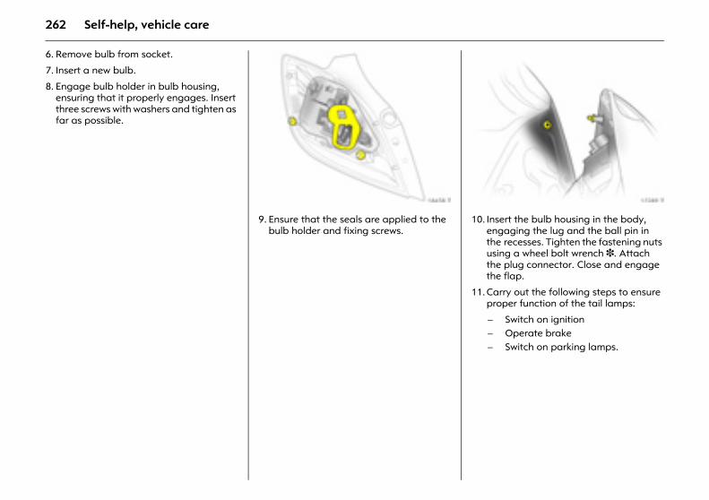
262 Self-help, vehicle care
6. Remove bulb from socket.
7. Insert a new bulb.
8. Engage bulb holder in bulb housing, ensuring that it properly engages. Insert three screws with washers and tighten as far as possible.
Picture no: 18458t.tif9. Ensure that the seals are applied to the
bulb holder and fixing screws.
Picture no: 17289t.tif10. Insert the bulb housing in the body,
engaging the lug and the ball pin in the recesses. Tighten the fastening nuts using a wheel bolt wrench 3. Attach the plug connector. Close and engage the flap.
11. Carry out the following steps to ensure proper function of the tail lamps:
– Switch on ignition– Operate brake– Switch on parking lamps.
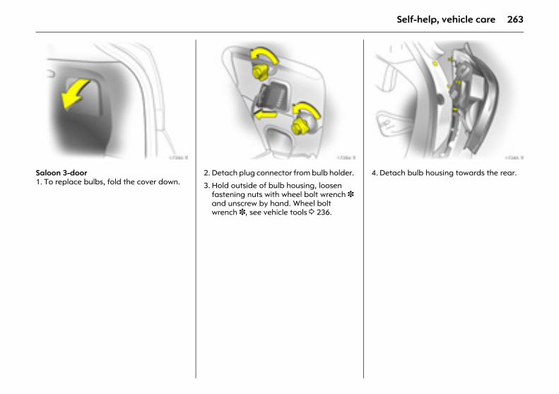
263Self-help, vehicle care
Picture no: 17290t.tifSaloon 3-door 1. To replace bulbs, fold the cover down.
Picture no: 17284t.tif2. Detach plug connector from bulb holder.
3. Hold outside of bulb housing, loosen fastening nuts with wheel bolt wrench 3 and unscrew by hand. Wheel bolt wrench 3, see vehicle tools 3 236.
Picture no: 17285t.tif4. Detach bulb housing towards the rear.
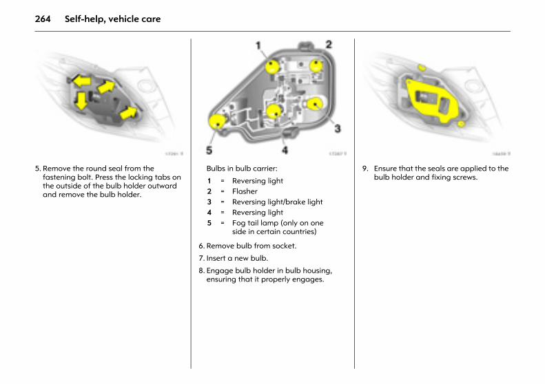
264 Self-help, vehicle care
Picture no: 17291t.tif5. Remove the round seal from the
fastening bolt. Press the locking tabs on the outside of the bulb holder outward and remove the bulb holder.
Picture no: 17287t.tifBulbs in bulb carrier:
6. Remove bulb from socket.
7. Insert a new bulb.
8. Engage bulb holder in bulb housing, ensuring that it properly engages.
Picture no: 18459t.tif9. Ensure that the seals are applied to the
bulb holder and fixing screws. 1 = Reversing light2 = Flasher3 = Reversing light/brake light4 = Reversing light5 = Fog tail lamp (only on one
side in certain countries)
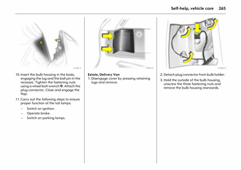
265Self-help, vehicle care
Picture no: 17289t.tif10. Insert the bulb housing in the body,
engaging the lug and the ball pin in the recesses. Tighten the fastening nuts using a wheel bolt wrench 3. Attach the plug connector. Close and engage the flap.
11. Carry out the following steps to ensure proper function of the tail lamps:
Picture no: 17293t.tifEstate, Delivery Van1. Disengage cover by pressing retaining
lugs and remove.
Picture no: 17294t.tif2. Detach plug connector from bulb holder.
3. Hold the outside of the bulb housing, unscrew the three fastening nuts and remove the bulb housing rearwards.
– Switch on ignition.– Operate brake.– Switch on parking lamps.
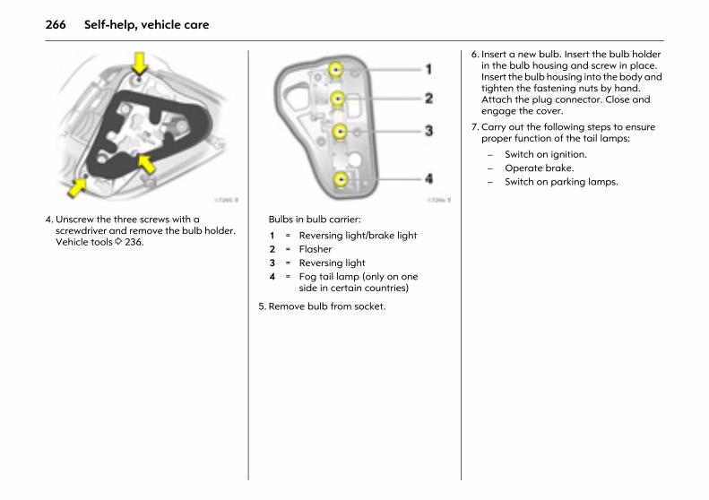
266 Self-help, vehicle care
Picture no: 17295t.tif4. Unscrew the three screws with a
screwdriver and remove the bulb holder. Vehicle tools 3 236.
Picture no: 17296t.tifBulbs in bulb carrier:
5. Remove bulb from socket.
6. Insert a new bulb. Insert the bulb holder in the bulb housing and screw in place. Insert the bulb housing into the body and tighten the fastening nuts by hand. Attach the plug connector. Close and engage the cover.
7. Carry out the following steps to ensure proper function of the tail lamps:
1 = Reversing light/brake light2 = Flasher3 = Reversing light4 = Fog tail lamp (only on one
side in certain countries)
– Switch on ignition.– Operate brake.– Switch on parking lamps.
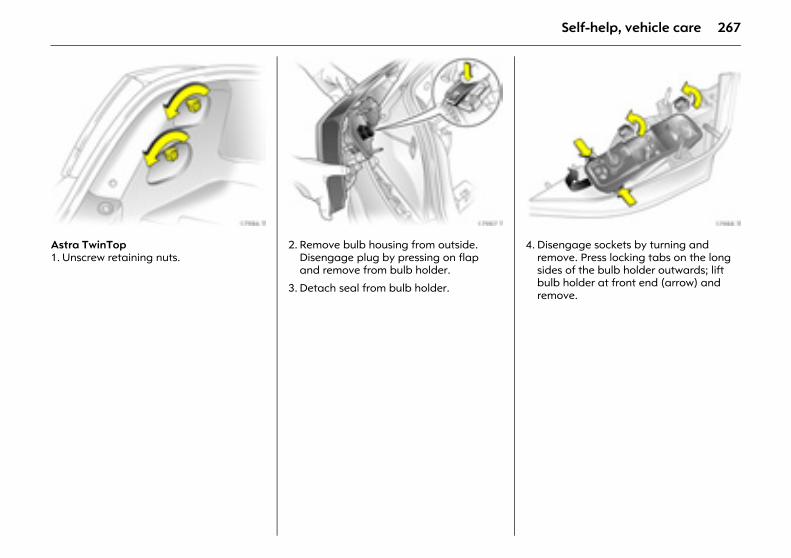
267Self-help, vehicle care
Picture no: 17986t.tifAstra TwinTop1. Unscrew retaining nuts.
Picture no: 17987t.tif2. Remove bulb housing from outside.
Disengage plug by pressing on flap and remove from bulb holder.
3. Detach seal from bulb holder.
Picture no: 17988t.tif4. Disengage sockets by turning and
remove. Press locking tabs on the long sides of the bulb holder outwards; lift bulb holder at front end (arrow) and remove.
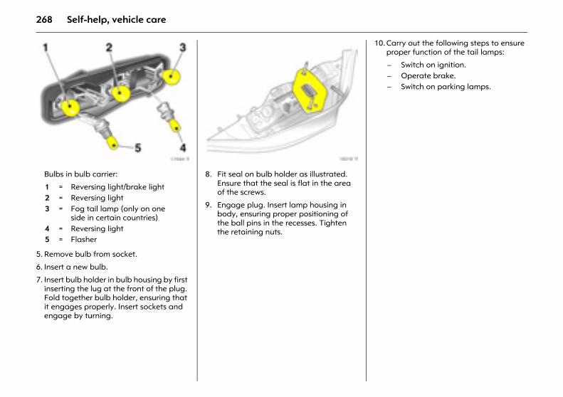
268 Self-help, vehicle care
Picture no: 17989t.tifBulbs in bulb carrier:
5. Remove bulb from socket.
6. Insert a new bulb.
7. Insert bulb holder in bulb housing by first inserting the lug at the front of the plug. Fold together bulb holder, ensuring that it engages properly. Insert sockets and engage by turning.
Picture no: 18018t.tif8. Fit seal on bulb holder as illustrated.
Ensure that the seal is flat in the area of the screws.
9. Engage plug. Insert lamp housing in body, ensuring proper positioning of the ball pins in the recesses. Tighten the retaining nuts.
10. Carry out the following steps to ensure proper function of the tail lamps:
1 = Reversing light/brake light2 = Reversing light3 = Fog tail lamp (only on one
side in certain countries)4 = Reversing light5 = Flasher
– Switch on ignition.– Operate brake.– Switch on parking lamps.
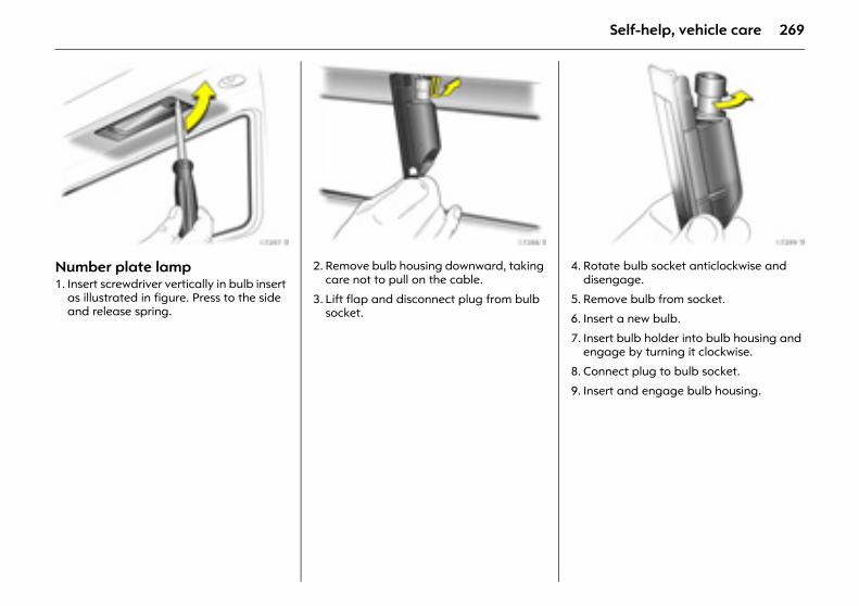
269Self-help, vehicle care
Picture no: 17297t.tifNumber plate lamp 1. Insert screwdriver vertically in bulb insert
as illustrated in figure. Press to the side and release spring.
Picture no: 17298t.tif2. Remove bulb housing downward, taking
care not to pull on the cable.
3. Lift flap and disconnect plug from bulb socket.
Picture no: 17299t.tif4. Rotate bulb socket anticlockwise and
disengage.
5. Remove bulb from socket.
6. Insert a new bulb.
7. Insert bulb holder into bulb housing and engage by turning it clockwise.
8. Connect plug to bulb socket.
9. Insert and engage bulb housing.
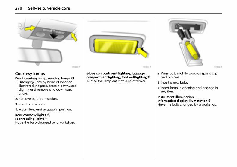
270 Self-help, vehicle care
Picture no: 17300t.tifCourtesy lamps Front courtesy lamp, reading lamps 3 1. Disengage lens by hand at location
illustrated in figure, press it downward slightly and remove at a downward angle.
2. Remove bulb from socket.
3. Insert a new bulb.
4. Mount lens and engage in position.
Rear courtesy lights 3, rear reading lights 3 Have the bulb changed by a workshop.
Picture no: 17301t.tifGlove compartment lighting, luggage compartment lighting, foot well lighting 3 1. Prise the lamp out with a screwdriver.
Picture no: 17302t.tif2. Press bulb slightly towards spring clip
and remove.
3. Insert a new bulb.
4. Insert lamp in opening and engage in position.
Instrument illumination, Information display illumination 3 Have the bulb changed by a workshop.
271Self-help, vehicle care
Vehicle careWhen caring for your vehicle, observe all national environmental regulations, particularly when washing it.
Regular, thorough care helps to improve the appearance of your vehicle and maintain its value over the years. It is also prerequisite for warranty claims for any paint or corrosion damage. The following pages contain tips for vehicle care which, if used properly, will help combat the unavoidable, damaging effects of the environment.
Washing The paintwork of your vehicle is exposed to environmental influences. Wash and wax the vehicle regularly. When using automatic car washes, select a programme which includes waxing.
Bird droppings, dead insects, resin, pollen and the like should be cleaned off immediately, as they contain aggressive constituents which can cause paint damage.
When using a car wash, follow the manufacturer’s instructions. Switch off the windscreen wipers and rear window wiper. Unscrew the antenna 3 and roof rack 3, standing on the door sill for ease of reach.
If you wash your vehicle by hand, make sure that the insides of the wings are also thoroughly rinsed out.
Clean edges and folds on opened doors and flaps as well as the areas they cover.
Thoroughly rinse off and leather-off the vehicle. Rinse leather frequently. Use separate leathers for paint and window surfaces: remnants of wax on the windows will impair vision.
Tar spots must not be removed with hard objects. Use Tar Removal Spray on painted surfaces.
Polishing and waxing Wax your vehicle regularly (at the latest when water no longer beads). Otherwise, the paintwork will dry out.
Polishing is necessary only if the paint has become dull or if solid deposits have become attached to it.
Paintwork polish with silicone forms a protective film, making waxing unnecessary.
Plastic body parts should not be treated with wax and polish.
272 Self-help, vehicle care
Wheels and tyres Do not use high-pressure jet cleaners.
Use a pH-neutral wheel cleaning agent to clean the wheels.
Wheels are painted and can be treated with the same agents as the body.
Paintwork damage Repair minor paintwork damage with a touch-up pen before rust forms. Entrust repair of major paintwork damage or rust to a workshop.
Exterior lights Headlamp and other protective lamp bezels are made of plastic. Do not use any abrasive or caustic agents, do not use an ice scraper, and do not clean them dry.
Plastic and rubber parts Plastic and rubber parts can be cleaned with the same agents as the rest of the body. Use interior cleaner if necessary. Do not use any other agent, and in particular do not use solvents or fuel. Do not use high-pressure jet cleaners.
Interior and upholstery Clean the vehicle interior, including the instrument panel fascia with a dry cloth only or with interior cleaner.
The instrument panel should only be cleaned using a soft damp cloth.
Clean fabric upholstery with a vacuum cleaner and brush. Use an upholstery cleaner to remove stains.
Clean seat belts with lukewarm water or interior cleaner.
Windows and wiper bladesClean using a soft lint-free cloth or chamois leather together with window cleaner or insect remover.
Make sure that the heating element on the inside of the window is not damaged when cleaning the window.
For mechanical removal of ice, use a sharp-edged ice scraper. Press the scraper firmly against the glass so that no dirt can get under it and scratch the glass.
Clean smearing wiper blades with a soft cloth and window cleaner.
Sun roof 3 Never clean with solvents or abrasive agents, fuels, aggressive media (e.g. paint cleaner, acetone-containing solutions etc.), acidic or highly alkaline media or abrasive pads.
No stickers may be applied to the sun roof. Caution
Open Velcro fasteners on clothing could damage seat upholstery. Make sure Velcro fasteners are closed.
273Self-help, vehicle care
Locks The locks are factory-lubricated with a high quality lock cylinder grease. This prevents the locks from freezing. Only use de-icer in urgent cases as this destroys the grease and damages the function of the locks. After using de-icer, have a workshop regrease the locks.
Engine compartment Areas of the engine compartment that are painted in the same colour as the vehicle must be looked after like any other painted surface.
It is advisable to wash the engine compartment before and after winter and preserve it with wax. Cover alternator and brake fluid reservoir with plastic sheets before washing the engine.
When washing the engine with a steam-jet cleaner, do not direct the steam jet at components of the anti-lock braking system, the air conditioning system, the climate control system or the belt drive and its components.
After washing the engine, have a workshop protect all parts in the engine compartment with protective wax.
Do not use high-pressure jet cleaners.
Underbody Parts of the underbody have PVC underbody protection while critical areas have a permanent protective wax coating.
Check the underbody after washing and have it waxed if necessary.
Bitumen/ rubber materials can damage the PVC coating. We recommend that you have underbody work carried out by a workshop
The underbody should be washed and its protective wax layer checked before and after the winter season.
Astra TwinTop Treat all seals, e. g. on the roof and windscreen frame, with silicone oil from time to time. Good contact between the fine rubber lips and the sealing surfaces prevents leaks and reduces clamping forces.
The roof can be held in an intermediate position for about 9 minutes by releasing the operating switch in order to clean roof spaces.
Intermediate roof position for cleaning 3 58.
Do not use high-pressure jet cleaners.
Towing equipment Do not clean the coupling ball bar with steam or high-pressure jet cleaners.
274 Opel Service, maintenance
Opel Service, maintenance
Planned maintenanceThe service intervals apply under normal operating conditions. For extreme operating conditions 3 281.
Service interval display 3 283.
European service intervalsEvery 30,000 km or annually, whichever occurs first
International service intervalsEvery 15,000 km or annually, whichever occurs first
ConfirmationService is confirmed in the relevant fields of the Service and Warranty Booklet. The service workshop fills out the date and mileage and provides its stamp and signature.
Make sure that the Service and Warranty Booklet is correctly filled out as proof of uninterrupted service is important to warranty and settlement claims and is an advantage when selling the vehicle.
Service planThe European Service Plan applies to the following countries: Andorra, Austria, Belgium, Cyprus, Czech Republic, Denmark, Estonia, Finland, France, Germany, Greece, Greenland, Hungary, Iceland, Ireland, Italy, Latvia, Lithuania, Luxembourg, Malta, Netherlands, Norway, Poland, Portugal, Slovakia, Slovenia, Spain, Sweden, Switzerland and the UK.
The International Service Plan applies to all other countries.
Planned maintenance ......................... 274 Service plan.......................................... 274 Additional servicing............................. 281 Recommended fluids and lubricants 281 Inspection system ................................ 283 Genuine Opel parts and accessories 284 Performing work .................................. 284 Engine oil .............................................. 285 Diesel fuel filter .................................... 287 Coolant ................................................. 287 Brakes ................................................... 288 Brake fluid ............................................ 288 Windscreen wiper replacement .......... 289 Windscreen and headlamp washer
systems 3........................................... 290 Battery .................................................. 290 Protecting electronic components ..... 291 Storage for a long period of time ...... 291 Putting the vehicle back into
operation ........................................... 291
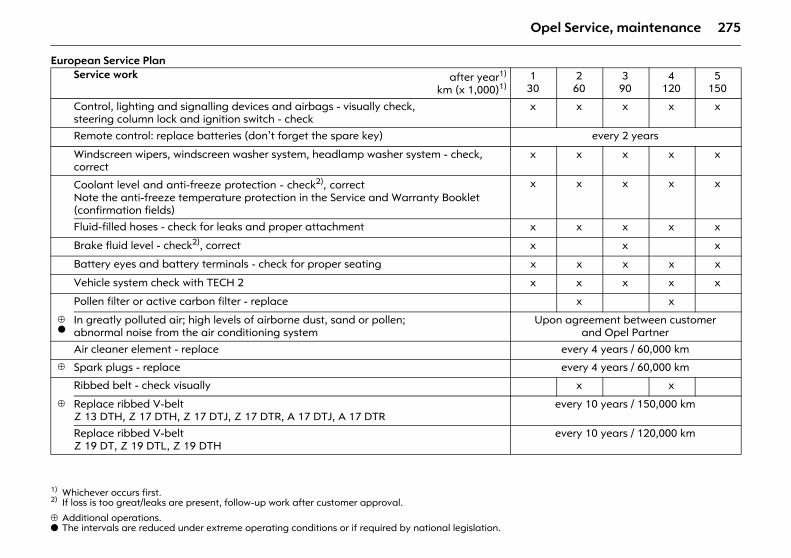
275Opel Service, maintenance
European Service Plan
⊕ Additional operations.o The intervals are reduced under extreme operating conditions or if required by national legislation.
Service work after year1)
km (x 1,000)1)
1) Whichever occurs first.
130
260
390
4120
5150
Control, lighting and signalling devices and airbags - visually check,steering column lock and ignition switch - check
x x x x x
Remote control: replace batteries (don’t forget the spare key) every 2 years
Windscreen wipers, windscreen washer system, headlamp washer system - check, correct
x x x x x
Coolant level and anti-freeze protection - check2), correctNote the anti-freeze temperature protection in the Service and Warranty Booklet (confirmation fields)
2) If loss is too great/leaks are present, follow-up work after customer approval.
x x x x x
Fluid-filled hoses - check for leaks and proper attachment x x x x x
Brake fluid level - check2), correct x x x
Battery eyes and battery terminals - check for proper seating x x x x x
Vehicle system check with TECH 2 x x x x x
Pollen filter or active carbon filter - replace x x
⊕o
In greatly polluted air; high levels of airborne dust, sand or pollen; abnormal noise from the air conditioning system
Upon agreement between customer and Opel Partner
Air cleaner element - replace every 4 years / 60,000 km
⊕ Spark plugs - replace every 4 years / 60,000 km
Ribbed belt - check visually x x
⊕ Replace ribbed V-beltZ 13 DTH, Z 17 DTH, Z 17 DTJ, Z 17 DTR, A 17 DTJ, A 17 DTR
every 10 years / 150,000 km
Replace ribbed V-beltZ 19 DT, Z 19 DTL, Z 19 DTH
every 10 years / 120,000 km
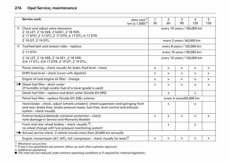
276 Opel Service, maintenance
⊕ Additional operations.o The intervals are reduced under extreme operating conditions or if required by national legislation.
Service work after year1)
km (x 1,000)1)
1) Whichever occurs first.
130
260
390
4120
5150
⊕ Check and adjust valve clearanceZ 16 LET, Z 16 XER, Z16XE1, Z 18 XER,Z 17 DTH, Z 17 DTJ, Z 17 DTR, A 17 DTJ, A 17 DTR
every 10 years / 150,000 km
Z 19 DT, Z 19 DTL every 2 years / 60,000 km
⊕ Toothed belt and tension roller - replace every 8 years / 120,000 km
Z 17 DTH every 10 years / 90,000 km
Z 16 LET, Z 16 XER, Z 16 XE1, Z 18 XER,Z/A 17 DTJ, Z/A 17 DTR, Z 19 DT, Z 19 DTL,
every 10 years / 150,000 km
Power steering - check visually for leaks; fluid level - check x x x x x
EHPS fluid level - check (cover with dipstick) x x x x x
Engine oil and engine oil filter - change x x x x x
⊕o Diesel fuel filter - drain water(if humidity is high and/or fuel of a lower grade is used)
x x x x x
Diesel fuel filter - replace and drain water (Grade EN 590) x x
Petrol fuel filter - replace (Grade EN 228), exterior every 4 years/60,000 km
Hand brake - check, adjust (wheels unladen); wheel suspension and springing front and rear, brake lines, brake pressure hoses, fuel lines, level control and exhaust system - check visually
x x
Exterior body/underbody corrosion protection - check; note damage in Service and Warranty Booklet
x x x x x
Front and rear wheel brakes - check visually 2); no wheel change with tyre pressure monitoring system!
2) If loss is too great/leaks are present, follow-up work after customer approval.
x x
⊕o Annual service check, if vehicle travels more than 20,000 km annually
Engine, transmission (AT, MT), A/C compressor - check visually for leaks2) x x x x x
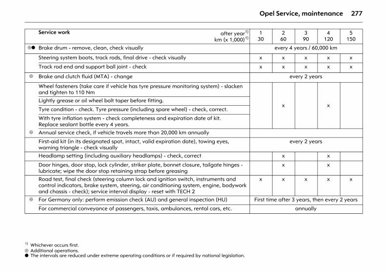
277Opel Service, maintenance
⊕ Additional operations.o The intervals are reduced under extreme operating conditions or if required by national legislation.
Service work after year1)
km (x 1,000)1)
1) Whichever occurs first.
130
260
390
4120
5150
⊕o Brake drum - remove, clean, check visually every 4 years / 60,000 km
Steering system boots, track rods, final drive - check visually x x x x x
Track rod end and support ball joint - check x x x x x
⊕ Brake and clutch fluid (MTA) - change every 2 years
Wheel fasteners (take care if vehicle has tyre pressure monitoring system) - slacken and tighten to 110 Nm
x xLightly grease or oil wheel bolt taper before fitting.
Tyre condition - check. Tyre pressure (including spare wheel) - check, correct.
With tyre inflation system - check completeness and expiration date of kit. Replace sealant bottle every 4 years.
⊕ Annual service check, if vehicle travels more than 20,000 km annually
First-aid kit (in its designated spot, intact, valid expiration date), towing eyes, warning triangle - check visually
every 2 years
Headlamp setting (including auxiliary headlamps) - check, correct x x
Door hinges, door stop, lock cylinder, striker plate, bonnet closure, tailgate hinges - lubricate; wipe the door stop retaining strap before greasing
x x
Road test, final check (steering column lock and ignition switch, instruments and control indicators, brake system, steering, air conditioning system, engine, bodywork and chassis - check); service interval display - reset with TECH 2
x x x x x
⊕ For Germany only: perform emission check (AU) and general inspection (HU) First time after 3 years, then every 2 years
For commercial conveyance of passengers, taxis, ambulances, rental cars, etc. annually
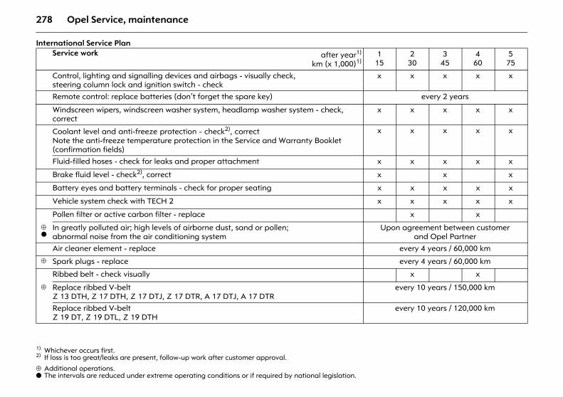
278 Opel Service, maintenance
International Service Plan
⊕ Additional operations.o The intervals are reduced under extreme operating conditions or if required by national legislation.
Service work after year1)
km (x 1,000)1)
1) Whichever occurs first.
115
230
345
460
575
Control, lighting and signalling devices and airbags - visually check,steering column lock and ignition switch - check
x x x x x
Remote control: replace batteries (don’t forget the spare key) every 2 years
Windscreen wipers, windscreen washer system, headlamp washer system - check, correct
x x x x x
Coolant level and anti-freeze protection - check2), correctNote the anti-freeze temperature protection in the Service and Warranty Booklet (confirmation fields)
2) If loss is too great/leaks are present, follow-up work after customer approval.
x x x x x
Fluid-filled hoses - check for leaks and proper attachment x x x x x
Brake fluid level - check2), correct x x x
Battery eyes and battery terminals - check for proper seating x x x x x
Vehicle system check with TECH 2 x x x x x
Pollen filter or active carbon filter - replace x x
⊕o
In greatly polluted air; high levels of airborne dust, sand or pollen; abnormal noise from the air conditioning system
Upon agreement between customer and Opel Partner
Air cleaner element - replace every 4 years / 60,000 km
⊕ Spark plugs - replace every 4 years / 60,000 km
Ribbed belt - check visually x x
⊕ Replace ribbed V-beltZ 13 DTH, Z 17 DTH, Z 17 DTJ, Z 17 DTR, A 17 DTJ, A 17 DTR
every 10 years / 150,000 km
Replace ribbed V-beltZ 19 DT, Z 19 DTL, Z 19 DTH
every 10 years / 120,000 km
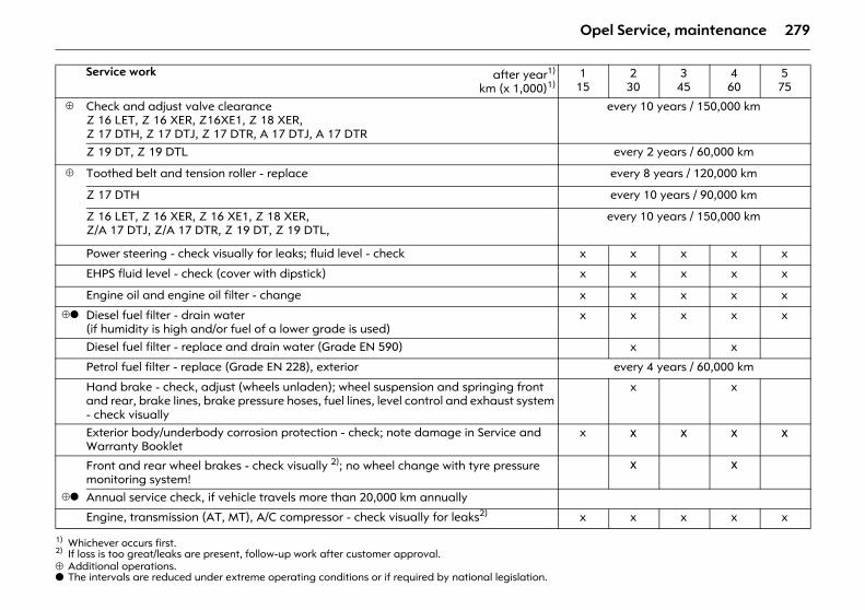
279Opel Service, maintenance
⊕ Additional operations.o The intervals are reduced under extreme operating conditions or if required by national legislation.
Service work after year1)
km (x 1,000)1)
1) Whichever occurs first.
115
230
345
460
575
⊕ Check and adjust valve clearanceZ 16 LET, Z 16 XER, Z16XE1, Z 18 XER,Z 17 DTH, Z 17 DTJ, Z 17 DTR, A 17 DTJ, A 17 DTR
every 10 years / 150,000 km
Z 19 DT, Z 19 DTL every 2 years / 60,000 km
⊕ Toothed belt and tension roller - replace every 8 years / 120,000 km
Z 17 DTH every 10 years / 90,000 km
Z 16 LET, Z 16 XER, Z 16 XE1, Z 18 XER,Z/A 17 DTJ, Z/A 17 DTR, Z 19 DT, Z 19 DTL,
every 10 years / 150,000 km
Power steering - check visually for leaks; fluid level - check x x x x x
EHPS fluid level - check (cover with dipstick) x x x x x
Engine oil and engine oil filter - change x x x x x
⊕o Diesel fuel filter - drain water(if humidity is high and/or fuel of a lower grade is used)
x x x x x
Diesel fuel filter - replace and drain water (Grade EN 590) x x
Petrol fuel filter - replace (Grade EN 228), exterior every 4 years / 60,000 km
Hand brake - check, adjust (wheels unladen); wheel suspension and springing front and rear, brake lines, brake pressure hoses, fuel lines, level control and exhaust system - check visually
x x
Exterior body/underbody corrosion protection - check; note damage in Service and Warranty Booklet
x x x x x
Front and rear wheel brakes - check visually 2); no wheel change with tyre pressure monitoring system!
2) If loss is too great/leaks are present, follow-up work after customer approval.
x x
⊕o Annual service check, if vehicle travels more than 20,000 km annually
Engine, transmission (AT, MT), A/C compressor - check visually for leaks2) x x x x x
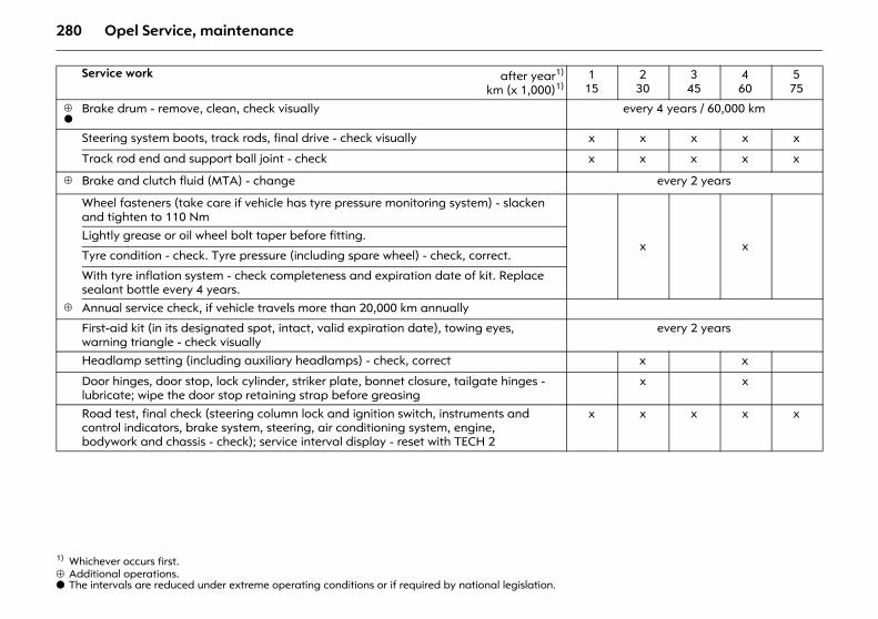
280 Opel Service, maintenance
⊕ Additional operations.o The intervals are reduced under extreme operating conditions or if required by national legislation.
Service work after year1)
km (x 1,000)1)
1) Whichever occurs first.
115
230
345
460
575
⊕o
Brake drum - remove, clean, check visually every 4 years / 60,000 km
Steering system boots, track rods, final drive - check visually x x x x x
Track rod end and support ball joint - check x x x x x
⊕ Brake and clutch fluid (MTA) - change every 2 years
Wheel fasteners (take care if vehicle has tyre pressure monitoring system) - slacken and tighten to 110 Nm
x xLightly grease or oil wheel bolt taper before fitting.
Tyre condition - check. Tyre pressure (including spare wheel) - check, correct.
With tyre inflation system - check completeness and expiration date of kit. Replace sealant bottle every 4 years.
⊕ Annual service check, if vehicle travels more than 20,000 km annually
First-aid kit (in its designated spot, intact, valid expiration date), towing eyes, warning triangle - check visually
every 2 years
Headlamp setting (including auxiliary headlamps) - check, correct x x
Door hinges, door stop, lock cylinder, striker plate, bonnet closure, tailgate hinges - lubricate; wipe the door stop retaining strap before greasing
x x
Road test, final check (steering column lock and ignition switch, instruments and control indicators, brake system, steering, air conditioning system, engine, bodywork and chassis - check); service interval display - reset with TECH 2
x x x x x
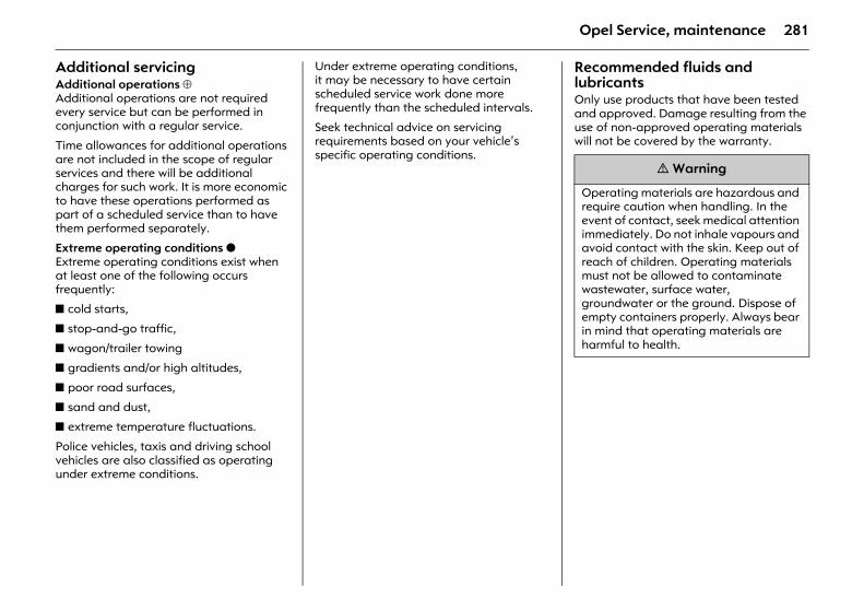
281Opel Service, maintenance
Additional servicingAdditional operations ⊕Additional operations are not required every service but can be performed in conjunction with a regular service.
Time allowances for additional operations are not included in the scope of regular services and there will be additional charges for such work. It is more economic to have these operations performed as part of a scheduled service than to have them performed separately.
Extreme operating conditions oExtreme operating conditions exist when at least one of the following occurs frequently:
z cold starts,
z stop-and-go traffic,
z wagon/trailer towing
z gradients and/or high altitudes,
z poor road surfaces,
z sand and dust,
z extreme temperature fluctuations.
Police vehicles, taxis and driving school vehicles are also classified as operating under extreme conditions.
Under extreme operating conditions, it may be necessary to have certain scheduled service work done more frequently than the scheduled intervals.
Seek technical advice on servicing requirements based on your vehicle’s specific operating conditions.
Recommended fluids and lubricants Only use products that have been tested and approved. Damage resulting from the use of non-approved operating materials will not be covered by the warranty.
9 Warning
Operating materials are hazardous and require caution when handling. In the event of contact, seek medical attention immediately. Do not inhale vapours and avoid contact with the skin. Keep out of reach of children. Operating materials must not be allowed to contaminate wastewater, surface water, groundwater or the ground. Dispose of empty containers properly. Always bear in mind that operating materials are harmful to health.
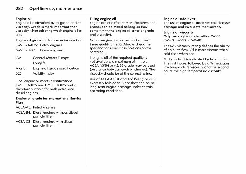
282 Opel Service, maintenance
Engine oilEngine oil is identified by its grade and its viscosity. Grade is more important than viscosity when selecting which engine oil to use.
Engine oil grade for European Service Plan
Opel engine oil meets classifications GM-LL-A-025 and GM-LL-B-025 and is therefore suitable for both petrol and diesel engines.
Engine oil grade for International Service Plan
Filling engine oilEngine oils of different manufacturers and brands can be mixed as long as they comply with the engine oil criteria (grade and viscosity).
Not all engine oils on the market meet these quality criteria. Always check the specifications and classifications on the container.
If engine oil of the required quality is not available, a maximum of 1 litre of ACEA A3/B4 or A3/B3 grade may be used (only once between each oil change). The viscosity should be of the correct rating.
Use of ACEA A1/B1 and A5/B5 engine oil is expressly forbidden, since they can cause long-term engine damage under certain operating conditions.
Engine oil additivesThe use of engine oil additives could cause damage and invalidate the warranty.
Engine oil viscosityOnly use engine oil viscosities 0W-30, 0W-40, 5W-30 or 5W-40.
The SAE viscosity rating defines the ability of an oil to flow. Oil is more viscous when cold than when hot.
Multigrade oil is indicated by two figures. The first figure, followed by a W, indicates low temperature viscosity and the second figure the high temperature viscosity.
GM-LL-A-025: Petrol enginesGM-LL-B-025: Diesel engines
GM General Motors EuropeLL LonglifeA or B Engine oil grade specification
025 Validity index
ACEA-A3: Petrol enginesACEA-B4: Diesel engines without diesel
particle filterACEA-C3 Diesel engines with diesel
particle filter
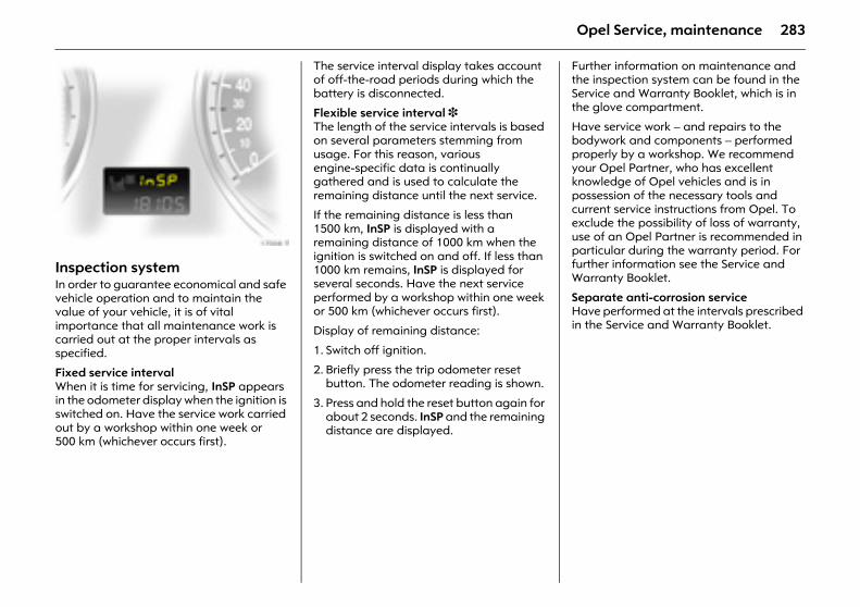
283Opel Service, maintenance
Picture no: 17008t.tifInspection system In order to guarantee economical and safe vehicle operation and to maintain the value of your vehicle, it is of vital importance that all maintenance work is carried out at the proper intervals as specified.
Fixed service interval When it is time for servicing, InSP appears in the odometer display when the ignition is switched on. Have the service work carried out by a workshop within one week or 500 km (whichever occurs first).
The service interval display takes account of off-the-road periods during which the battery is disconnected.
Flexible service interval 3 The length of the service intervals is based on several parameters stemming from usage. For this reason, various engine-specific data is continually gathered and is used to calculate the remaining distance until the next service.
If the remaining distance is less than 1500 km, InSP is displayed with a remaining distance of 1000 km when the ignition is switched on and off. If less than 1000 km remains, InSP is displayed for several seconds. Have the next service performed by a workshop within one week or 500 km (whichever occurs first).
Display of remaining distance:
1. Switch off ignition.
2. Briefly press the trip odometer reset button. The odometer reading is shown.
3. Press and hold the reset button again for about 2 seconds. InSP and the remaining distance are displayed.
Further information on maintenance and the inspection system can be found in the Service and Warranty Booklet, which is in the glove compartment.
Have service work – and repairs to the bodywork and components – performed properly by a workshop. We recommend your Opel Partner, who has excellent knowledge of Opel vehicles and is in possession of the necessary tools and current service instructions from Opel. To exclude the possibility of loss of warranty, use of an Opel Partner is recommended in particular during the warranty period. For further information see the Service and Warranty Booklet.
Separate anti-corrosion service Have performed at the intervals prescribed in the Service and Warranty Booklet.
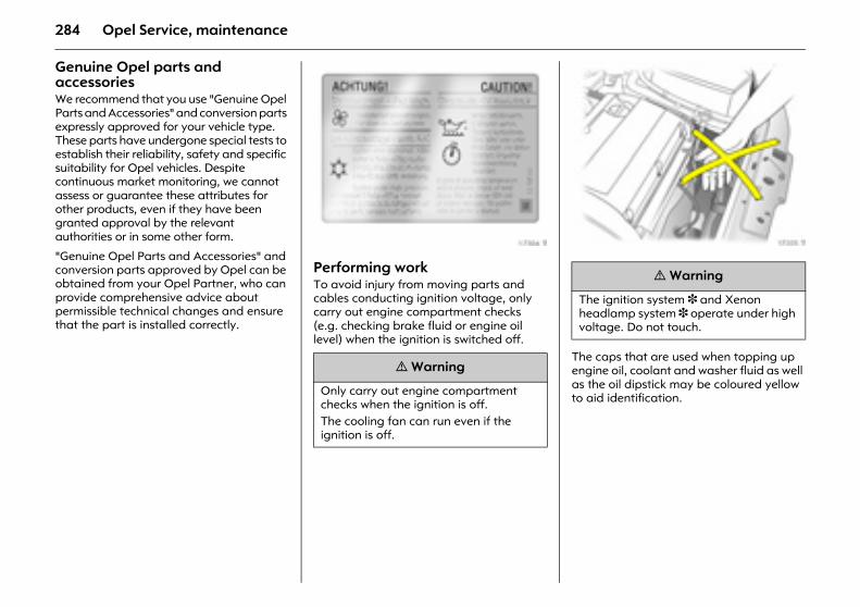
284 Opel Service, maintenance
Genuine Opel parts and accessories We recommend that you use "Genuine Opel Parts and Accessories" and conversion parts expressly approved for your vehicle type. These parts have undergone special tests to establish their reliability, safety and specific suitability for Opel vehicles. Despite continuous market monitoring, we cannot assess or guarantee these attributes for other products, even if they have been granted approval by the relevant authorities or in some other form.
"Genuine Opel Parts and Accessories" and conversion parts approved by Opel can be obtained from your Opel Partner, who can provide comprehensive advice about permissible technical changes and ensure that the part is installed correctly.
Picture no: 17304t.tifPerforming work To avoid injury from moving parts and cables conducting ignition voltage, only carry out engine compartment checks (e.g. checking brake fluid or engine oil level) when the ignition is switched off.
Picture no: 17305t.tif
The caps that are used when topping up engine oil, coolant and washer fluid as well as the oil dipstick may be coloured yellow to aid identification.
9 Warning
Only carry out engine compartment checks when the ignition is off. The cooling fan can run even if the ignition is off.
9 Warning
The ignition system 3 and Xenon headlamp system 3 operate under high voltage. Do not touch.
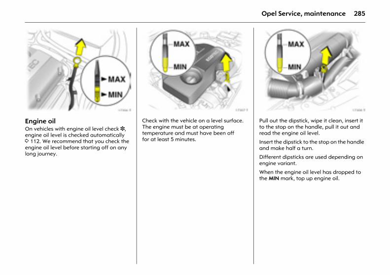
285Opel Service, maintenance
Picture no: 17306t.tifEngine oil On vehicles with engine oil level check 3, engine oil level is checked automatically 3 112. We recommend that you check the engine oil level before starting off on any long journey.
Picture no: 17307t.tifCheck with the vehicle on a level surface. The engine must be at operating temperature and must have been off for at least 5 minutes.
Picture no: 17308t.tifPull out the dipstick, wipe it clean, insert it to the stop on the handle, pull it out and read the engine oil level.
Insert the dipstick to the stop on the handle and make half a turn.
Different dipsticks are used depending on engine variant.
When the engine oil level has dropped to the MIN mark, top up engine oil.
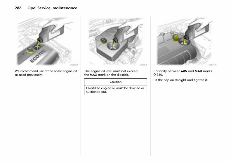
286 Opel Service, maintenance
Picture no: 17309t.tifWe recommend use of the same engine oil as used previously.
Picture no: 17310t.tifThe engine oil level must not exceed the MAX mark on the dipstick.
Picture no: 17311t.tifCapacity between MIN and MAX marks 3 330.
Fit the cap on straight and tighten it. Caution
Overfilled engine oil must be drained or suctioned out.
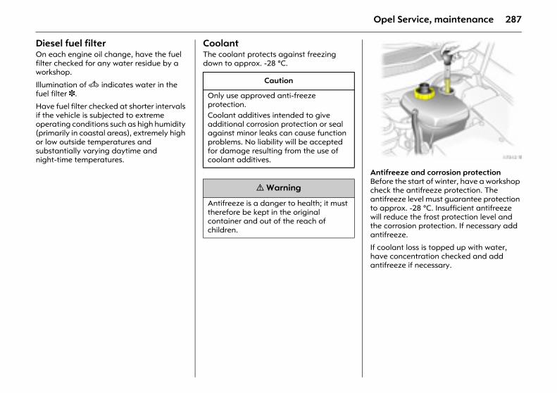
287Opel Service, maintenance
Diesel fuel filter On each engine oil change, have the fuel filter checked for any water residue by a workshop.
Illumination of A indicates water in the fuel filter 3.
Have fuel filter checked at shorter intervals if the vehicle is subjected to extreme operating conditions such as high humidity (primarily in coastal areas), extremely high or low outside temperatures and substantially varying daytime and night-time temperatures.
Coolant The coolant protects against freezing down to approx. -28 °C.
.
Picture no: 17312t.tifAntifreeze and corrosion protection Before the start of winter, have a workshop check the antifreeze protection. The antifreeze level must guarantee protection to approx. -28 °C. Insufficient antifreeze will reduce the frost protection level and the corrosion protection. If necessary add antifreeze.
If coolant loss is topped up with water, have concentration checked and add antifreeze if necessary.
Caution
Only use approved anti-freeze protection. Coolant additives intended to give additional corrosion protection or seal against minor leaks can cause function problems. No liability will be accepted for damage resulting from the use of coolant additives.
9 Warning
Antifreeze is a danger to health; it must therefore be kept in the original container and out of the reach of children.
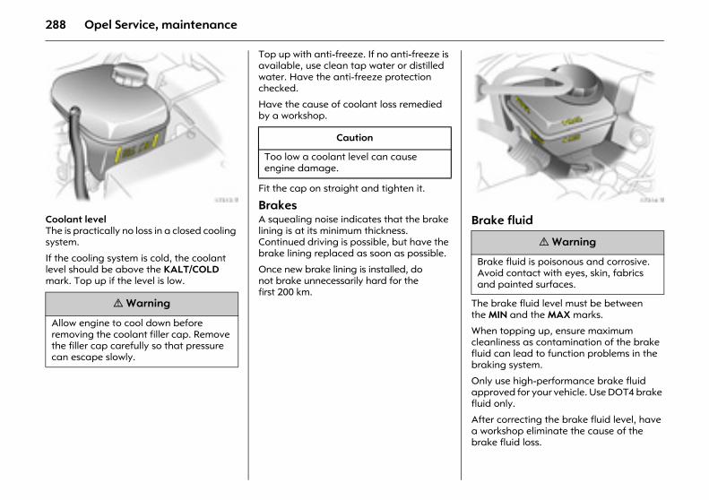
288 Opel Service, maintenance
Picture no: 17313t.tifCoolant level The is practically no loss in a closed cooling system.
If the cooling system is cold, the coolant level should be above the KALT/COLD mark. Top up if the level is low.
Top up with anti-freeze. If no anti-freeze is available, use clean tap water or distilled water. Have the anti-freeze protection checked.
Have the cause of coolant loss remedied by a workshop.
Fit the cap on straight and tighten it.
Brakes A squealing noise indicates that the brake lining is at its minimum thickness. Continued driving is possible, but have the brake lining replaced as soon as possible.
Once new brake lining is installed, do not brake unnecessarily hard for the first 200 km.
Picture no: 17314t.tifBrake fluid
The brake fluid level must be between the MIN and the MAX marks.
When topping up, ensure maximum cleanliness as contamination of the brake fluid can lead to function problems in the braking system.
Only use high-performance brake fluid approved for your vehicle. Use DOT4 brake fluid only.
After correcting the brake fluid level, have a workshop eliminate the cause of the brake fluid loss.
9 Warning
Allow engine to cool down before removing the coolant filler cap. Remove the filler cap carefully so that pressure can escape slowly.
Caution
Too low a coolant level can cause engine damage.
9 Warning
Brake fluid is poisonous and corrosive. Avoid contact with eyes, skin, fabrics and painted surfaces.
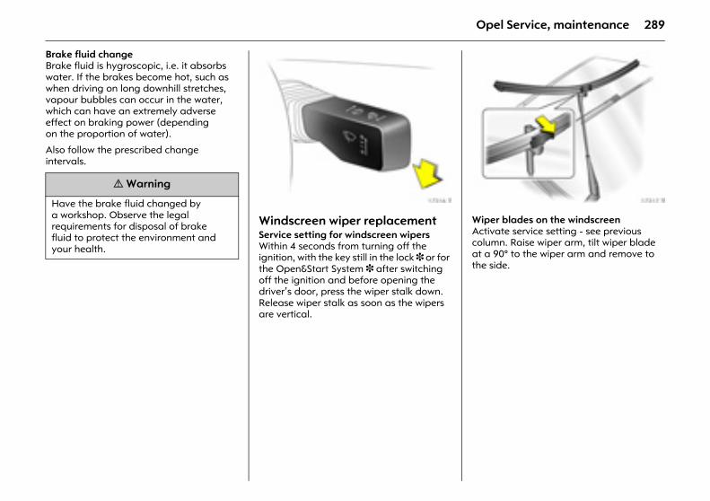
289Opel Service, maintenance
Brake fluid change Brake fluid is hygroscopic, i.e. it absorbs water. If the brakes become hot, such as when driving on long downhill stretches, vapour bubbles can occur in the water, which can have an extremely adverse effect on braking power (depending on the proportion of water).
Also follow the prescribed change intervals.
Picture no: 17316t.tifWindscreen wiper replacement Service setting for windscreen wipers Within 4 seconds from turning off the ignition, with the key still in the lock 3 or for the Open&Start System 3 after switching off the ignition and before opening the driver’s door, press the wiper stalk down. Release wiper stalk as soon as the wipers are vertical.
Picture no: 17317t.tifWiper blades on the windscreen Activate service setting - see previous column. Raise wiper arm, tilt wiper blade at a 90° to the wiper arm and remove to the side.
9 Warning
Have the brake fluid changed by a workshop. Observe the legal requirements for disposal of brake fluid to protect the environment and your health.
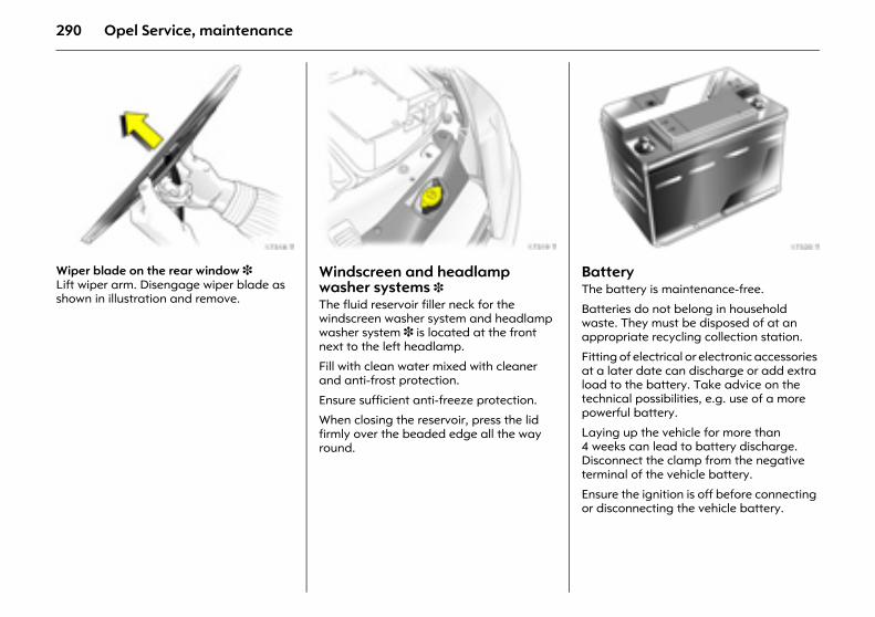
290 Opel Service, maintenance
Picture no: 17318t.tifWiper blade on the rear window 3 Lift wiper arm. Disengage wiper blade as shown in illustration and remove.
Picture no: 17319t.tifWindscreen and headlamp washer systems 3 The fluid reservoir filler neck for the windscreen washer system and headlamp washer system 3 is located at the front next to the left headlamp.
Fill with clean water mixed with cleaner and anti-frost protection.
Ensure sufficient anti-freeze protection.
When closing the reservoir, press the lid firmly over the beaded edge all the way round.
Picture no: 17320t.tifBattery The battery is maintenance-free.
Batteries do not belong in household waste. They must be disposed of at an appropriate recycling collection station.
Fitting of electrical or electronic accessories at a later date can discharge or add extra load to the battery. Take advice on the technical possibilities, e.g. use of a more powerful battery.
Laying up the vehicle for more than 4 weeks can lead to battery discharge. Disconnect the clamp from the negative terminal of the vehicle battery.
Ensure the ignition is off before connecting or disconnecting the vehicle battery.
291Opel Service, maintenance
Protecting electronic components In order to prevent faults in electronic components in the electrical system, never connect or disconnect battery with engine running or ignition switched on. Never start engine with battery disconnected, e.g. when starting using jump leads.
To avoid damaging the vehicle, do not make any modifications to the electrical system, e. g. connecting additional consumers or tampering with electronic control units (chip tuning).
Storage for a long period of time In order to prevent damage, the following must be done if the vehicle will be stored for several months.
z Wash and wax the vehicle 3 271.
z Have the wax in the engine compartment and underbody checked.
z Clean and wax rubber seals. Intermediate position of Astra Twin-Top roof for cleaning 3 58.
z Change the engine oil.
z Check frost and corrosion protection 3 287.
z Check coolant level, top up antifreeze if necessary 3 288.
z Empty windscreen washer system and headlamp washer system.
z Increase tyre pressure to specified value for full load 3 319.
z Park vehicle in dry, well ventilated place. With manual transmission or manual transmission automated 3, engage 1st or reverse gear. With automatic transmission 3, move selector lever to P. Use chocks or the like to prevent the vehicle from rolling.
z Do not apply hand brake.
z Disconnect the clamp from the negative terminal of the vehicle battery.
Putting the vehicle back into operationPerform the following work before recommissioning the vehicle:
z Connect the clamp from the negative terminal of the vehicle battery.
z Check tyre pressure 3 319.
z Top up windscreen washer system 3 290.
z Check engine oil level 3 285.
z Check coolant level 3 288.
z Fit the number plates if necessary.
9 Warning
Electronic ignition systems generate very high voltages. Do not touch the ignition system; high voltage can be fatal.
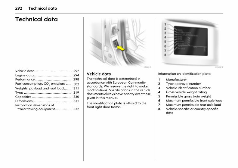
292 Technical data
Technical data
Picture no: 17321t.tifVehicle data The technical data is determined in accordance with European Community standards. We reserve the right to make modifications. Specifications in the vehicle documents always have priority over those given in this manual.
The identification plate is affixed to the front right door frame.
Picture no: 17322t.tifInformation on identification plate:
Vehicle data......................................... 292 Engine data.......................................... 294 Performance,........................................ 298 Fuel consumption, CO2 emissions ...... 302 Weights, payload and roof load ........ 311 Tyres ..................................................... 319 Capacities ............................................ 330 Dimensions ........................................... 331 Installation dimensions of
trailer towing equipment.................. 332
1 Manufacturer2 Type approval number3 Vehicle identification number4 Gross vehicle weight rating5 Permissible gross train weight6 Maximum permissible front axle load7 Maximum permissible rear axle load8 Vehicle-specific or country-specific
data
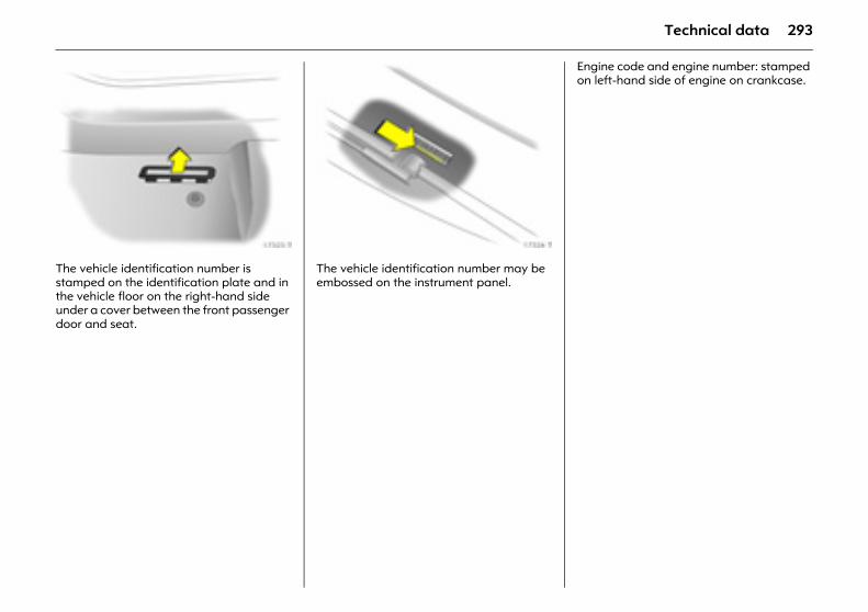
293Technical data
Picture no: 17323t.tifThe vehicle identification number is stamped on the identification plate and in the vehicle floor on the right-hand side under a cover between the front passenger door and seat.
Picture no: 17324t.tifThe vehicle identification number may be embossed on the instrument panel.
Engine code and engine number: stamped on left-hand side of engine on crankcase.
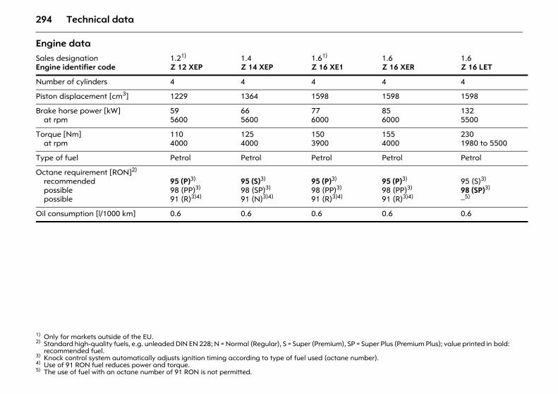
294 Technical data
Engine data Sales designationEngine identifier code
1.21) Z 12 XEP
1) Only for markets outside of the EU.
1.4 Z 14 XEP
1.61) Z 16 XE1
1.6 Z 16 XER
1.6 Z 16 LET
Number of cylinders 4 4 4 4 4
Piston displacement [cm3] 1229 1364 1598 1598 1598
Brake horse power [kW]at rpm
595600
665600
776000
856000
1325500
Torque [Nm]at rpm
1104000
1254000
1503900
1554000
2301980 to 5500
Type of fuel Petrol Petrol Petrol Petrol Petrol
Octane requirement [RON]2)
recommendedpossiblepossible
2) Standard high-quality fuels, e.g. unleaded DIN EN 228; N = Normal (Regular), S = Super (Premium), SP = Super Plus (Premium Plus); value printed in bold: recommended fuel.
95 (P)3)
98 (PP)3)
91 (R)3)4)
3) Knock control system automatically adjusts ignition timing according to type of fuel used (octane number).
95 (S)3)
98 (SP)3)
91 (N)3)4)
4) Use of 91 RON fuel reduces power and torque.
95 (P)3)
98 (PP)3)
91 (R)3)4)
95 (P)3)
98 (PP)3)
91 (R)3)4)
95 (S)3)
98 (SP)3)
–5)
5) The use of fuel with an octane number of 91 RON is not permitted.
Oil consumption [l/1000 km] 0.6 0.6 0.6 0.6 0.6
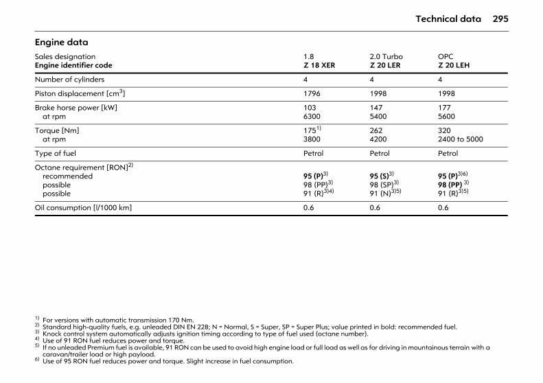
295Technical data
Engine data Sales designationEngine identifier code
1.8 Z 18 XER
2.0 TurboZ 20 LER
OPCZ 20 LEH
Number of cylinders 4 4 4
Piston displacement [cm3] 1796 1998 1998
Brake horse power [kW]at rpm
1036300
1475400
1775600
Torque [Nm]at rpm
1751)
3800
1) For versions with automatic transmission 170 Nm.
2624200
3202400 to 5000
Type of fuel Petrol Petrol Petrol
Octane requirement [RON]2)
recommendedpossiblepossible
2) Standard high-quality fuels, e.g. unleaded DIN EN 228; N = Normal, S = Super, SP = Super Plus; value printed in bold: recommended fuel.
95 (P)3)
98 (PP)3)
91 (R)3)4)
3) Knock control system automatically adjusts ignition timing according to type of fuel used (octane number).4) Use of 91 RON fuel reduces power and torque.
95 (S)3)
98 (SP)3)
91 (N)3)5)
5) If no unleaded Premium fuel is available, 91 RON can be used to avoid high engine load or full load as well as for driving in mountainous terrain with a caravan/trailer load or high payload.
95 (P)3)6)
98 (PP) 3)
91 (R)3)5)
6) Use of 95 RON fuel reduces power and torque. Slight increase in fuel consumption.
Oil consumption [l/1000 km] 0.6 0.6 0.6
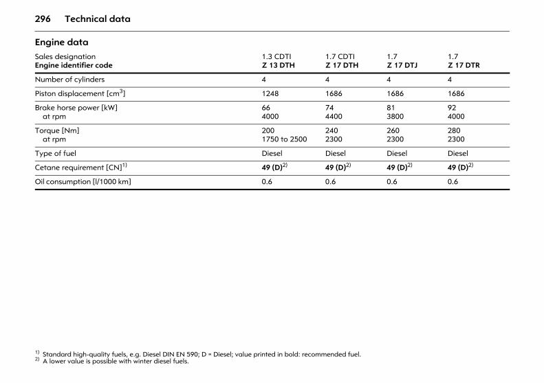
296 Technical data
Engine data Sales designationEngine identifier code
1.3 CDTIZ 13 DTH
1.7 CDTI Z 17 DTH
1.7 Z 17 DTJ
1.7 Z 17 DTR
Number of cylinders 4 4 4 4
Piston displacement [cm3] 1248 1686 1686 1686
Brake horse power [kW]at rpm
664000
744400
813800
924000
Torque [Nm]at rpm
2001750 to 2500
2402300
2602300
2802300
Type of fuel Diesel Diesel Diesel Diesel
Cetane requirement [CN]1)
1) Standard high-quality fuels, e.g. Diesel DIN EN 590; D = Diesel; value printed in bold: recommended fuel.
49 (D)2)
2) A lower value is possible with winter diesel fuels.
49 (D)2) 49 (D)2) 49 (D)2)
Oil consumption [l/1000 km] 0.6 0.6 0.6 0.6
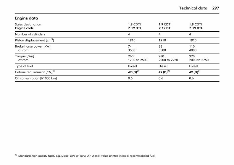
297Technical data
Engine data Sales designationEngine code
1.9 CDTI Z 19 DTL
1.9 CDTI Z 19 DT
1.9 CDTI Z 19 DTH
Number of cylinders 4 4 4
Piston displacement [cm3] 1910 1910 1910
Brake horse power [kW]at rpm
743500
883500
1104000
Torque [Nm]at rpm
2601700 to 2500
2802000 to 2750
3202000 to 2750
Type of fuel Diesel Diesel Diesel
Cetane requirement [CN]1)
1) Standard high-quality fuels, e.g. Diesel DIN EN 590; D = Diesel; value printed in bold: recommended fuel.
49 (D)2) 49 (D)2) 49 (D)2)
Oil consumption [l/1000 km] 0.6 0.6 0.6
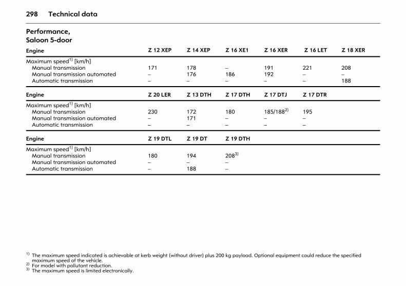
298 Technical data
Performance, Saloon 5-door Engine Z 12 XEP Z 14 XEP Z 16 XE1 Z 16 XER Z 16 LET Z 18 XER
Maximum speed1) [km/h]Manual transmissionManual transmission automatedAutomatic transmission
1) The maximum speed indicated is achievable at kerb weight (without driver) plus 200 kg payload. Optional equipment could reduce the specified maximum speed of the vehicle.
171––
178176 –
–186–
191192–
221––
208–188
Engine Z 20 LER Z 13 DTH Z 17 DTH Z 17 DTJ Z 17 DTR
Maximum speed1) [km/h]Manual transmissionManual transmission automatedAutomatic transmission
230––
172171–
180––
185/1882)
––
2) For model with pollutant reduction.
195– –
Engine Z 19 DTL Z 19 DT Z 19 DTH
Maximum speed1) [km/h]Manual transmissionManual transmission automatedAutomatic transmission
180––
194–188
2083)
––
3) The maximum speed is limited electronically.
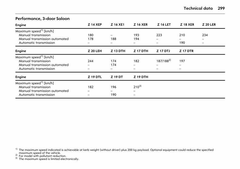
299Technical data
Performance, 3-door Saloon Engine Z 14 XEP Z 16 XE1 Z 16 XER Z 16 LET Z 18 XER Z 20 LER
Maximum speed1) [km/h]Manual transmissionManual transmission automatedAutomatic transmission
1) The maximum speed indicated is achievable at kerb weight (without driver) plus 200 kg payload. Optional equipment could reduce the specified maximum speed of the vehicle.
180178 –
–188 –
193194–
223––
210–190
234––
Engine Z 20 LEH Z 13 DTH Z 17 DTH Z 17 DTJ Z 17 DTR
Maximum speed1) [km/h]Manual transmissionManual transmission automatedAutomatic transmission
244––
174174 –
182––
187/1882)
– –
2) For model with pollutant reduction.
197– –
Engine Z 19 DTL Z 19 DT Z 19 DTH
Maximum speed1) [km/h]Manual transmissionManual transmission automatedAutomatic transmission
182––
196–190
2103)
––
3) The maximum speed is limited electronically.
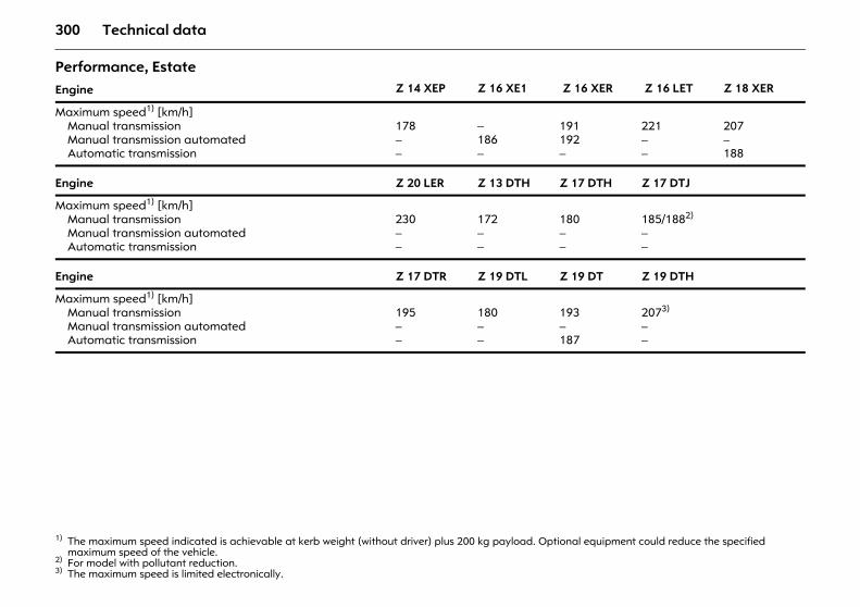
300 Technical data
Performance, Estate
Engine Z 14 XEP Z 16 XE1 Z 16 XER Z 16 LET Z 18 XER
Maximum speed1) [km/h]Manual transmissionManual transmission automatedAutomatic transmission
1) The maximum speed indicated is achievable at kerb weight (without driver) plus 200 kg payload. Optional equipment could reduce the specified maximum speed of the vehicle.
178– –
–186 –
191192 –
221– –
207–188
Engine Z 20 LER Z 13 DTH Z 17 DTH Z 17 DTJ
Maximum speed1) [km/h]Manual transmissionManual transmission automatedAutomatic transmission
230– –
172– –
180––
185/1882)
– –
2) For model with pollutant reduction.
Engine Z 17 DTR Z 19 DTL Z 19 DT Z 19 DTH
Maximum speed1) [km/h]Manual transmissionManual transmission automatedAutomatic transmission
195– –
180– –
193–187
2073)
––
3) The maximum speed is limited electronically.
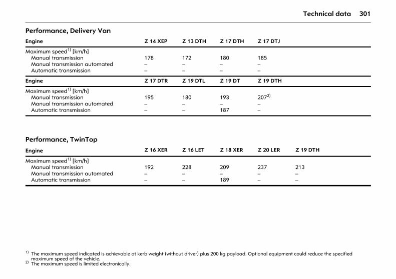
301Technical data
Performance, Delivery Van Engine Z 14 XEP Z 13 DTH Z 17 DTH Z 17 DTJ
Maximum speed1) [km/h]Manual transmissionManual transmission automatedAutomatic transmission
1) The maximum speed indicated is achievable at kerb weight (without driver) plus 200 kg payload. Optional equipment could reduce the specified maximum speed of the vehicle.
178– –
172– –
180– –
185– –
Engine Z 17 DTR Z 19 DTL Z 19 DT Z 19 DTH
Maximum speed1) [km/h]Manual transmissionManual transmission automatedAutomatic transmission
195– –
180– –
193–187
2072)
– –
2) The maximum speed is limited electronically.
Performance, TwinTop
Engine Z 16 XER Z 16 LET Z 18 XER Z 20 LER Z 19 DTH
Maximum speed1) [km/h]Manual transmissionManual transmission automatedAutomatic transmission
192––
228– –
209–189
237– –
213– –
302 Technical data
Fuel consumption, CO2 emissions Directive 80/1268/EEC (last modified by 2004/3/EC) has applied for the measurement of fuel consumption since 1996.
The directive is oriented to actual driving practices: Urban driving is rated at approx. 1/3 and off-road driving with approx. 2/3 (urban and extra-urban consumption). Cold starts and acceleration phases are also taken into consideration.
The specification of CO2 emission is also a constituent of the directive.
The figures given must not be taken as a guarantee for the actual fuel consumption of a particular vehicle.
All values are based on the EU base model with standard equipment.
The calculation of fuel consumption as specified by directive 2004/3/EC takes account of the vehicle’s kerb weight, ascertained in accordance with these regulations. Optional extras may result in slightly higher fuel consumption and CO2 emission levels than those quoted.
Saving fuel, Protecting the environment 3 190.
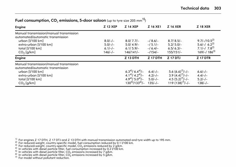
303Technical data
Fuel consumption, CO2 emissions, 5-door saloon (up to tyre size 205 mm1))
1) For engines Z 17 DTH, Z 17 DTJ and Z 13 DTH with manual transmission automated and tyre width up to 195 mm.
Engine Z 12 XEP Z 14 XEP Z 16 XE1 Z 16 XER Z 18 XER
Manual transmission/manual transmission automated/automatic transmission
urban [l/100 km]extra-urban [l/100 km]total [l/100 km]CO2 [g/km]
8.0/–/– 5.0/–/– 6.1/–/–146/–/–
8.0/ 7.7/– 5.0/ 4.9/– 6.1/ 5.9/–146/141/–
–/ 8.6/––/ 5.1/––/ 6.4/––/154/–
8.7/ 8.5/– 5.2/ 5.0/– 6.5/ 6.3/–155/151/–
9.7/–/10.52)
5.6/–/ 6.22)
7.1/–/ 7.82)
169/–/ 1863)
2) For reduced-weight, country-specific model, fuel consumption reduced by 0.1 l/100 km.3) For reduced-weight, country-specific model, CO2 emissions reduced by 2 g/km.
Engine Z 13 DTH Z 17 DTH Z 17 DTJ Z 17 DTR
Manual transmission/manual transmission automated/automatic transmission
urban [l/100 km]extra-urban [l/100 km]total [l/100 km]CO2 [g/km]
6.34)/ 6.44)/– 4.14)/ 4.24)/– 4.94)/ 5.04)/– 1305)/1336)/–
4) In vehicles with diesel particle filter, fuel consumption increased by 0.2 l/100 km.5) In vehicles with diesel particle filter, CO2 emissions increased by 7 g/km.6) In vehicles with diesel particle filter, CO2 emissions increased by 5 g/km.
6.4/–/– 4.2/–/– 5.0/–/–135/–/–
5.6 (6.6)7)/–/– 3.9 (4.4)7)/–/– 4.5 (5.2)7)/–/– 119 (138)7)/–/–
7) For model without pollutant reduction.
6.6/–/– 4.4/–/– 5.2/–/– 138/–/–
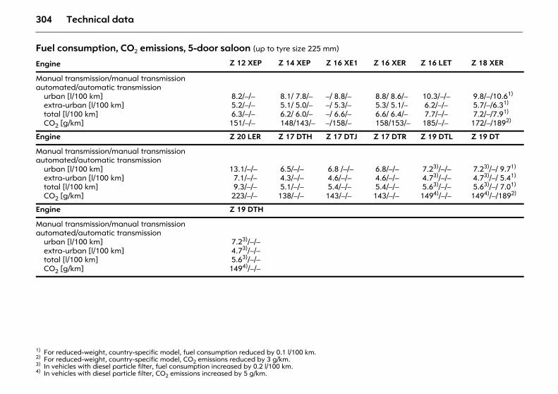
304 Technical data
Fuel consumption, CO2 emissions, 5-door saloon (up to tyre size 225 mm)
Engine Z 12 XEP Z 14 XEP Z 16 XE1 Z 16 XER Z 16 LET Z 18 XER
Manual transmission/manual transmission automated/automatic transmission
urban [l/100 km]extra-urban [l/100 km]total [l/100 km]CO2 [g/km]
8.2/–/– 5.2/–/– 6.3/–/–151/–/–
8.1/ 7.8/– 5.1/ 5.0/– 6.2/ 6.0/– 148/143/–
–/ 8.8/––/ 5.3/––/ 6.6/––/158/–
8.8/ 8.6/– 5.3/ 5.1/– 6.6/ 6.4/– 158/153/–
10.3/–/– 6.2/–/– 7.7/–/– 185/–/–
9.8/–/10.61)
5.7/–/6.31)
7.2/–/7.91)
172/–/1892)
1) For reduced-weight, country-specific model, fuel consumption reduced by 0.1 l/100 km.2) For reduced-weight, country-specific model, CO2 emissions reduced by 3 g/km.
Engine Z 20 LER Z 17 DTH Z 17 DTJ Z 17 DTR Z 19 DTL Z 19 DT
Manual transmission/manual transmission automated/automatic transmission
urban [l/100 km]extra-urban [l/100 km]total [l/100 km]CO2 [g/km]
13.1/–/– 7.1/–/– 9.3/–/– 223/–/–
6.5/–/– 4.3/–/– 5.1/–/–138/–/–
6.8 /–/– 4.6/–/– 5.4/–/–143/–/–
6.8/–/– 4.6/–/– 5.4/–/–143/–/–
7.23)/–/– 4.73)/–/– 5.63)/–/–1494)/–/–
3) In vehicles with diesel particle filter, fuel consumption increased by 0.2 l/100 km.4) In vehicles with diesel particle filter, CO2 emissions increased by 5 g/km.
7.23)/–/ 9.71)
4.73)/–/ 5.41)
5.63)/–/ 7.01)
1494)/–/1892)
Engine Z 19 DTH
Manual transmission/manual transmission automated/automatic transmission
urban [l/100 km]extra-urban [l/100 km]total [l/100 km]CO2 [g/km]
7.23)/–/– 4.73)/–/– 5.63)/–/–1494)/–/–
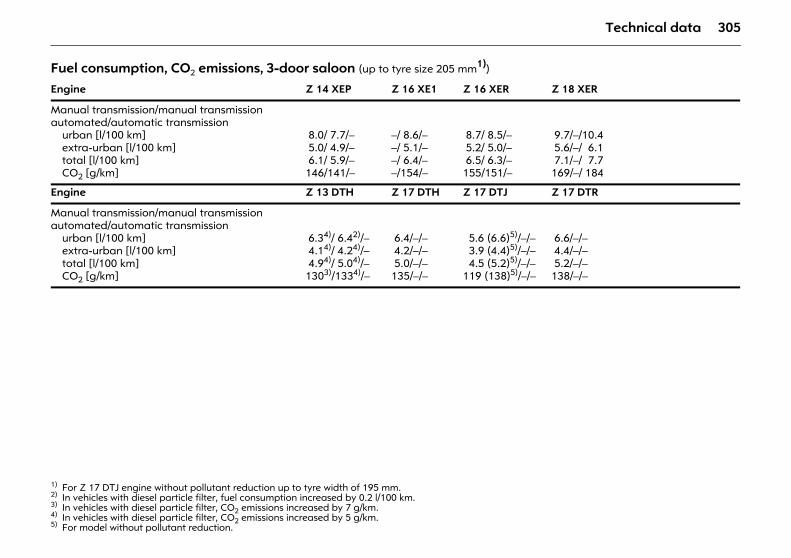
305Technical data
Fuel consumption, CO2 emissions, 3-door saloon (up to tyre size 205 mm1))
1) For Z 17 DTJ engine without pollutant reduction up to tyre width of 195 mm.
Engine Z 14 XEP Z 16 XE1 Z 16 XER Z 18 XER
Manual transmission/manual transmission automated/automatic transmission
urban [l/100 km]extra-urban [l/100 km]total [l/100 km]CO2 [g/km]
8.0/ 7.7/– 5.0/ 4.9/– 6.1/ 5.9/–146/141/–
–/ 8.6/––/ 5.1/––/ 6.4/––/154/–
8.7/ 8.5/– 5.2/ 5.0/– 6.5/ 6.3/–155/151/–
9.7/–/10.4 5.6/–/ 6.1 7.1/–/ 7.7169/–/ 184
Engine Z 13 DTH Z 17 DTH Z 17 DTJ Z 17 DTR
Manual transmission/manual transmission automated/automatic transmission
urban [l/100 km]extra-urban [l/100 km]total [l/100 km]CO2 [g/km]
6.34)/ 6.42)/– 4.14)/ 4.24)/– 4.94)/ 5.04)/–1303)/1334)/–
2) In vehicles with diesel particle filter, fuel consumption increased by 0.2 l/100 km.3) In vehicles with diesel particle filter, CO2 emissions increased by 7 g/km.4) In vehicles with diesel particle filter, CO2 emissions increased by 5 g/km.
6.4/–/– 4.2/–/– 5.0/–/–135/–/–
5.6 (6.6)5)/–/– 3.9 (4.4)5)/–/– 4.5 (5.2)5)/–/–119 (138)5)/–/–
5) For model without pollutant reduction.
6.6/–/– 4.4/–/– 5.2/–/–138/–/–
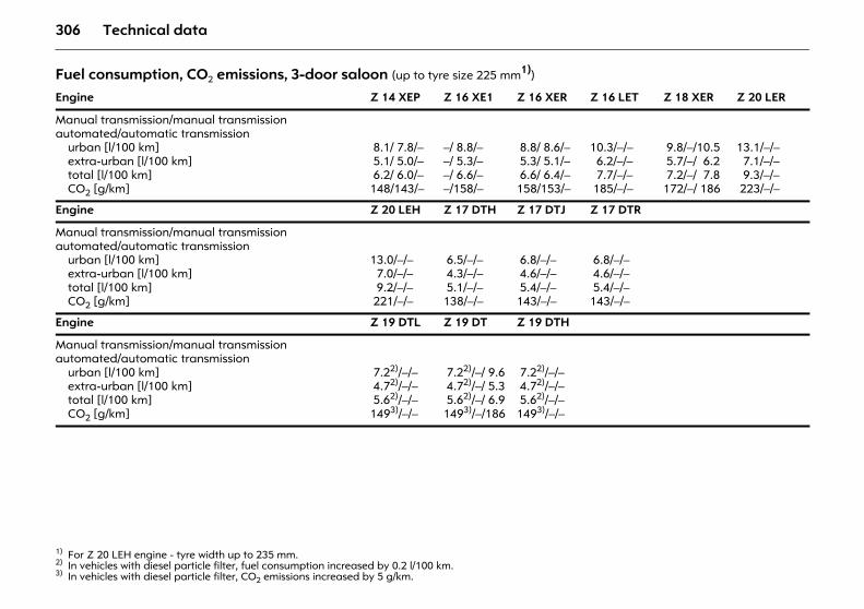
306 Technical data
Fuel consumption, CO2 emissions, 3-door saloon (up to tyre size 225 mm1))
1) For Z 20 LEH engine - tyre width up to 235 mm.
Engine Z 14 XEP Z 16 XE1 Z 16 XER Z 16 LET Z 18 XER Z 20 LER
Manual transmission/manual transmission automated/automatic transmission
urban [l/100 km]extra-urban [l/100 km]total [l/100 km]CO2 [g/km]
8.1/ 7.8/– 5.1/ 5.0/– 6.2/ 6.0/–148/143/–
–/ 8.8/––/ 5.3/––/ 6.6/––/158/–
8.8/ 8.6/– 5.3/ 5.1/– 6.6/ 6.4/–158/153/–
10.3/–/– 6.2/–/– 7.7/–/– 185/–/–
9.8/–/10.5 5.7/–/ 6.2 7.2/–/ 7.8172/–/ 186
13.1/–/– 7.1/–/– 9.3/–/– 223/–/–
Engine Z 20 LEH Z 17 DTH Z 17 DTJ Z 17 DTR
Manual transmission/manual transmission automated/automatic transmission
urban [l/100 km]extra-urban [l/100 km]total [l/100 km]CO2 [g/km]
13.0/–/– 7.0/–/– 9.2/–/– 221/–/–
6.5/–/– 4.3/–/– 5.1/–/–138/–/–
6.8/–/– 4.6/–/– 5.4/–/–143/–/–
6.8/–/– 4.6/–/– 5.4/–/–143/–/–
Engine Z 19 DTL Z 19 DT Z 19 DTH
Manual transmission/manual transmission automated/automatic transmission
urban [l/100 km]extra-urban [l/100 km]total [l/100 km]CO2 [g/km]
7.22)/–/– 4.72)/–/– 5.62)/–/–1493)/–/–
2) In vehicles with diesel particle filter, fuel consumption increased by 0.2 l/100 km.3) In vehicles with diesel particle filter, CO2 emissions increased by 5 g/km.
7.22)/–/ 9.6 4.72)/–/ 5.3 5.62)/–/ 6.91493)/–/186
7.22)/–/– 4.72)/–/– 5.62)/–/–1493)/–/–
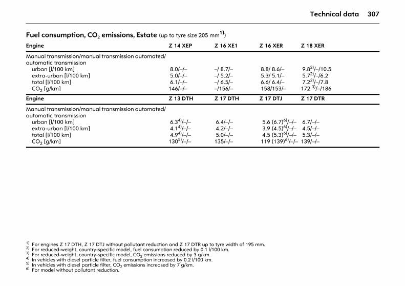
307Technical data
Fuel consumption, CO2 emissions, Estate (up to tyre size 205 mm1))
1) For engines Z 17 DTH, Z 17 DTJ without pollutant reduction and Z 17 DTR up to tyre width of 195 mm.
Engine Z 14 XEP Z 16 XE1 Z 16 XER Z 18 XER
Manual transmission/manual transmission automated/automatic transmission
urban [l/100 km]extra-urban [l/100 km]total [l/100 km]CO2 [g/km]
8.0/–/– 5.0/–/– 6.1/–/–146/–/–
–/ 8.7/––/ 5.2/––/ 6.5/––/156/–
8.8/ 8.6/– 5.3/ 5.1/– 6.6/ 6.4/– 158/153/–
9.82)/–/10.5 5.72)/–/6.2 7.22)/–/7.8172 3)/–/186
2) For reduced-weight, country-specific model, fuel consumption reduced by 0.1 l/100 km.3) For reduced-weight, country-specific model, CO2 emissions reduced by 3 g/km.
Engine Z 13 DTH Z 17 DTH Z 17 DTJ Z 17 DTR
Manual transmission/manual transmission automated/automatic transmission
urban [l/100 km]extra-urban [l/100 km]total [l/100 km]CO2 [g/km]
6.34)/–/– 4.14)/–/– 4.94)/–/–1305)/–/–
4) In vehicles with diesel particle filter, fuel consumption increased by 0.2 l/100 km.5) In vehicles with diesel particle filter, CO2 emissions increased by 7 g/km.
6.4/–/– 4.2/–/– 5.0/–/–135/–/–
5.6 (6.7)6)/–/– 3.9 (4.5)6)/–/– 4.5 (5.3)6)/–/– 119 (139)6)/–/–
6) For model without pollutant reduction.
6.7/–/– 4.5/–/– 5.3/–/–139/–/–
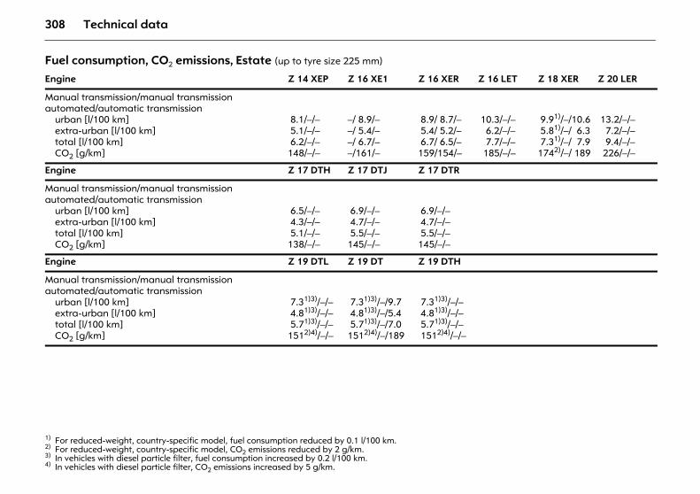
308 Technical data
Fuel consumption, CO2 emissions, Estate (up to tyre size 225 mm)
Engine Z 14 XEP Z 16 XE1 Z 16 XER Z 16 LET Z 18 XER Z 20 LER
Manual transmission/manual transmission automated/automatic transmission
urban [l/100 km]extra-urban [l/100 km]total [l/100 km]CO2 [g/km]
8.1/–/– 5.1/–/– 6.2/–/–148/–/–
–/ 8.9/––/ 5.4/––/ 6.7/––/161/–
8.9/ 8.7/– 5.4/ 5.2/– 6.7/ 6.5/–159/154/–
10.3/–/– 6.2/–/– 7.7/–/– 185/–/–
9.91)/–/10.6 5.81)/–/ 6.3 7.31)/–/ 7.91742)/–/ 189
1) For reduced-weight, country-specific model, fuel consumption reduced by 0.1 l/100 km.2) For reduced-weight, country-specific model, CO2 emissions reduced by 2 g/km.
13.2/–/– 7.2/–/– 9.4/–/– 226/–/–
Engine Z 17 DTH Z 17 DTJ Z 17 DTR
Manual transmission/manual transmission automated/automatic transmission
urban [l/100 km]extra-urban [l/100 km]total [l/100 km]CO2 [g/km]
6.5/–/– 4.3/–/– 5.1/–/–138/–/–
6.9/–/– 4.7/–/– 5.5/–/–145/–/–
6.9/–/– 4.7/–/– 5.5/–/–145/–/–
Engine Z 19 DTL Z 19 DT Z 19 DTH
Manual transmission/manual transmission automated/automatic transmission
urban [l/100 km]extra-urban [l/100 km]total [l/100 km]CO2 [g/km]
7.31)3)/–/– 4.81)3)/–/– 5.71)3)/–/–1512)4)/–/–
3) In vehicles with diesel particle filter, fuel consumption increased by 0.2 l/100 km.4) In vehicles with diesel particle filter, CO2 emissions increased by 5 g/km.
7.31)3)/–/9.7 4.81)3)/–/5.4 5.71)3)/–/7.01512)4)/–/189
7.31)3)/–/– 4.81)3)/–/– 5.71)3)/–/– 1512)4)/–/–
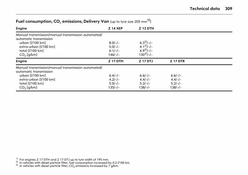
309Technical data
Fuel consumption, CO2 emissions, Delivery Van (up to tyre size 205 mm1))
1) For engines Z 17 DTH and Z 17 DTJ up to tyre width of 195 mm.
Engine Z 14 XEP Z 13 DTH
Manual transmission/manual transmission automated/automatic transmission
urban [l/100 km]extra-urban [l/100 km]total [l/100 km]CO2 [g/km]
8.0/–/– 5.0/–/– 6.1/–/–146/–/–
6.32)/–/– 4.12)/–/– 4.92)/–/–1303)/–/–
2) In vehicles with diesel particle filter, fuel consumption increased by 0.2 l/100 km.3) In vehicles with diesel particle filter, CO2 emissions increased by 7 g/km.
Engine Z 17 DTH Z 17 DTJ Z 17 DTR
Manual transmission/manual transmission automated/automatic transmission
urban [l/100 km]extra-urban [l/100 km]total [l/100 km]CO2 [g/km]
6.4/–/– 4.2/–/– 5.0/–/–135/–/–
6.6/–/– 4.4/–/– 5.2/–/–138/–/–
6.6/–/– 4.4/–/– 5.2/–/–138/–/–
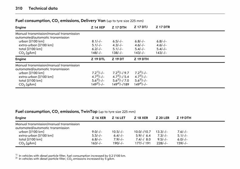
310 Technical data
Fuel consumption, CO2 emissions, Delivery Van (up to tyre size 225 mm)
Engine Z 14 XEP Z 17 DTH Z 17 DTJ Z 17 DTR
Manual transmission/manual transmission automated/automatic transmission
urban [l/100 km]extra-urban [l/100 km]total [l/100 km]CO2 [g/km]
8.1/–/– 5.1/–/– 6.2/–/–148/–/–
6.5/–/– 4.3/–/– 5.1/–/–138/–/–
6.8/–/– 4.6/–/– 5.4/–/–143/–/–
6.8/–/– 4.6/–/– 5.4/–/–143/–/–
Engine Z 19 DTL Z 19 DT Z 19 DTH
Manual transmission/manual transmission automated/automatic transmission
urban [l/100 km]extra-urban [l/100 km]total [l/100 km]CO2 [g/km]
7.21)/–/– 4.73)/–/– 5.63)/–/–1492)/–/–
1) In vehicles with diesel particle filter, fuel consumption increased by 0.2 l/100 km.2) In vehicles with diesel particle filter, CO2 emissions increased by 5 g/km.
7.23)/–/ 9.7 4.73)/–/ 5.4 5.63)/–/ 7.01494)/–/189
7.23)/–/– 4.73)/–/– 5.63)/–/–1494)/–/–
Fuel consumption, CO2 emissions, TwinTop (up to tyre size 225 mm)
Engine Z 16 XER Z 16 LET Z 18 XER Z 20 LER Z 19 DTH
Manual transmission/manual transmission automated/automatic transmission
urban [l/100 km]extra-urban [l/100 km]total [l/100 km]CO2 [g/km]
9.0/–/– 5.5/–/– 6.8/–/–163/–/–
10.5/–/– 6.4/–/– 7.9/–/– 190/–/–
10.0/–/10.7 5.9/–/ 6.4 7.4/–/ 8.0 177/–/ 191
13.3/–/– 7.3/–/– 9.5/–/– 228/–/–
7.6/–/– 5.1/–/– 6.0/–/–159/–/–
311Technical data
Weights, payload and roof load The payload is the difference between the permitted gross vehicle weight (see identification plate 3 292) and the EC kerb weight.
To calculate the kerb weight, enter the data for your vehicle below:
is the EC kerb weight.
Optional equipment and accessories increase the kerb weight, which means that the payload will also change slightly.
Note the weights given in the vehicle documents.
The combined total of front and rear axle loads must not exceed the permissible gross vehicle weight. For example, if the front axle is bearing its maximum permissible load, the rear axle can only bear a load that is equal to the gross vehicle weight minus the front axle load.
With a connected trailer and full load on the towing vehicle including all passengers, in the saloon the maximum permitted rear axle load (see rating plate or vehicle documents) may be exceeded by 65 kg (5-door) or 70 kg (3-door), and the maximum gross vehicle weight by 45 kg. In the Estate, the maximum permitted rear axle load may be exceeded by 60 kg and the maximum gross vehicle weight by 30 kg. If the maximum permitted rear axle load is exceeded, a top speed of 100 km/h applies. If lower top speeds are stipulated nationally when towing a trailer these must be observed.
See the identification plate or vehicle documents for permissible axle loads.
Roof loadThe permissible roof load is 75 kg and 100 kg for caravan with roof railing. The roof load is the combined weight of the roof rack and the load.
No roof load is permitted with the Astra TwinTop or vehicles with a panoramic window.
Driving hints 3 188. Roof rack, caravan/trailer towing 3 219.
z Kerb weight from table 1 3 312 +.............. kg
z Additional weight of equipment versions from table 2 3 316 +.............. kg
z Weight of heavy accessories from table 3 3 318 +.............. kg
Total =.............. kg
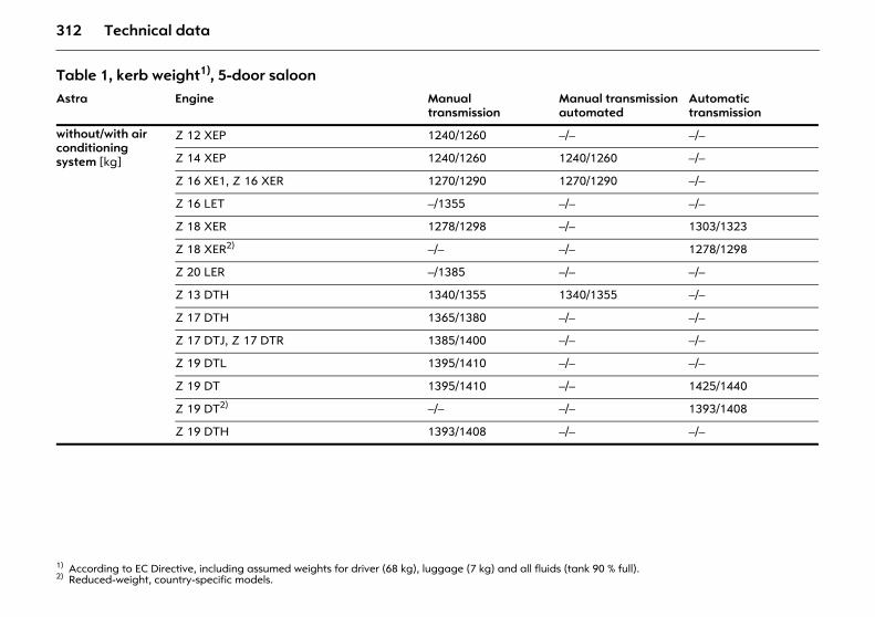
312 Technical data
Table 1, kerb weight1), 5-door saloon
1) According to EC Directive, including assumed weights for driver (68 kg), luggage (7 kg) and all fluids (tank 90 % full).
Astra Engine Manual transmission
Manual transmission automated
Automatic transmission
without/with air conditioning system [kg]
Z 12 XEP 1240/1260 –/– –/–
Z 14 XEP 1240/1260 1240/1260 –/–
Z 16 XE1, Z 16 XER 1270/1290 1270/1290 –/–
Z 16 LET –/1355 –/– –/–
Z 18 XER 1278/1298 –/– 1303/1323
Z 18 XER2)
2) Reduced-weight, country-specific models.
–/– –/– 1278/1298
Z 20 LER –/1385 –/– –/–
Z 13 DTH 1340/1355 1340/1355 –/–
Z 17 DTH 1365/1380 –/– –/–
Z 17 DTJ, Z 17 DTR 1385/1400 –/– –/–
Z 19 DTL 1395/1410 –/– –/–
Z 19 DT 1395/1410 –/– 1425/1440
Z 19 DT2) –/– –/– 1393/1408
Z 19 DTH 1393/1408 –/– –/–
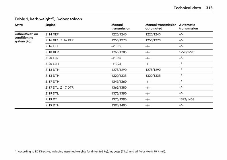
313Technical data
Table 1, kerb weight1), 3-door saloon
1) According to EC Directive, including assumed weights for driver (68 kg), luggage (7 kg) and all fluids (tank 90 % full).
Astra Engine Manual transmission
Manual transmission automated
Automatic transmission
without/with air conditioning system [kg]
Z 14 XEP 1220/1240 1220/1240 –/–
Z 16 XE1, Z 16 XER 1250/1270 1250/1270 –/–
Z 16 LET –/1335 –/– –/–
Z 18 XER 1265/1285 –/– 1278/1298
Z 20 LER –/1365 –/– –/–
Z 20 LEH –/1393 –/– –/–
Z 13 DTH 1278/1290 1278/1290 –/–
Z 13 DTH 1320/1335 1320/1335 –/–
Z 17 DTH 1345/1360 –/– –/–
Z 17 DTJ, Z 17 DTR 1365/1380 –/– –/–
Z 19 DTL 1375/1390 –/– –/–
Z 19 DT 1375/1390 –/– 1393/1408
Z 19 DTH 1390/1405 –/– –/–
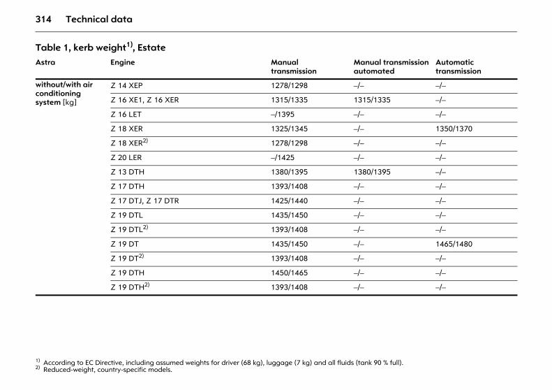
314 Technical data
Table 1, kerb weight1), Estate
1) According to EC Directive, including assumed weights for driver (68 kg), luggage (7 kg) and all fluids (tank 90 % full).
Astra Engine Manual transmission
Manual transmission automated
Automatic transmission
without/with air conditioning system [kg]
Z 14 XEP 1278/1298 –/– –/–
Z 16 XE1, Z 16 XER 1315/1335 1315/1335 –/–
Z 16 LET –/1395 –/– –/–
Z 18 XER 1325/1345 –/– 1350/1370
Z 18 XER2)
2) Reduced-weight, country-specific models.
1278/1298 –/– –/–
Z 20 LER –/1425 –/– –/–
Z 13 DTH 1380/1395 1380/1395 –/–
Z 17 DTH 1393/1408 –/– –/–
Z 17 DTJ, Z 17 DTR 1425/1440 –/– –/–
Z 19 DTL 1435/1450 –/– –/–
Z 19 DTL2) 1393/1408 –/– –/–
Z 19 DT 1435/1450 –/– 1465/1480
Z 19 DT2) 1393/1408 –/– –/–
Z 19 DTH 1450/1465 –/– –/–
Z 19 DTH2) 1393/1408 –/– –/–
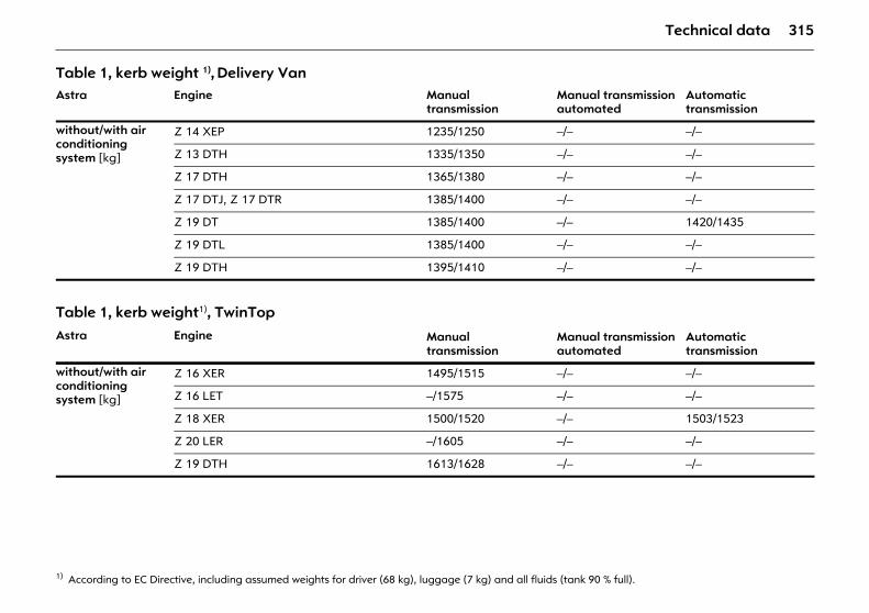
315Technical data
Table 1, kerb weight 1), Delivery Van
1) According to EC Directive, including assumed weights for driver (68 kg), luggage (7 kg) and all fluids (tank 90 % full).
Astra Engine Manual transmission
Manual transmission automated
Automatic transmission
without/with air conditioning system [kg]
Z 14 XEP 1235/1250 –/– –/–
Z 13 DTH 1335/1350 –/– –/–
Z 17 DTH 1365/1380 –/– –/–
Z 17 DTJ, Z 17 DTR 1385/1400 –/– –/–
Z 19 DT 1385/1400 –/– 1420/1435
Z 19 DTL 1385/1400 –/– –/–
Z 19 DTH 1395/1410 –/– –/–
Table 1, kerb weight1), TwinTopAstra Engine Manual
transmissionManual transmission automated
Automatic transmission
without/with air conditioning system [kg]
Z 16 XER 1495/1515 –/– –/–
Z 16 LET –/1575 –/– –/–
Z 18 XER 1500/1520 –/– 1503/1523
Z 20 LER –/1605 –/– –/–
Z 19 DTH 1613/1628 –/– –/–
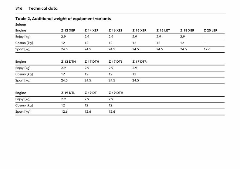
316 Technical data
Table 2, Additional weight of equipment variantsSaloon
Engine Z 12 XEP Z 14 XEP Z 16 XE1 Z 16 XER Z 16 LET Z 18 XER Z 20 LER
Enjoy [kg] 2.9 2.9 2.9 2.9 2.9 2.9 –
Cosmo [kg] 12 12 12 12 12 12 –
Sport [kg] 24.5 24.5 24.5 24.5 24.5 24.5 12.6
Engine Z 13 DTH Z 17 DTH Z 17 DTJ Z 17 DTR
Enjoy [kg] 2.9 2.9 2.9 2.9
Cosmo [kg] 12 12 12 12
Sport [kg] 24.5 24.5 24.5 24.5
Engine Z 19 DTL Z 19 DT Z 19 DTH
Enjoy [kg] 2.9 2.9 2.9
Cosmo [kg] 12 12 12
Sport [kg] 12.6 12.6 12.6
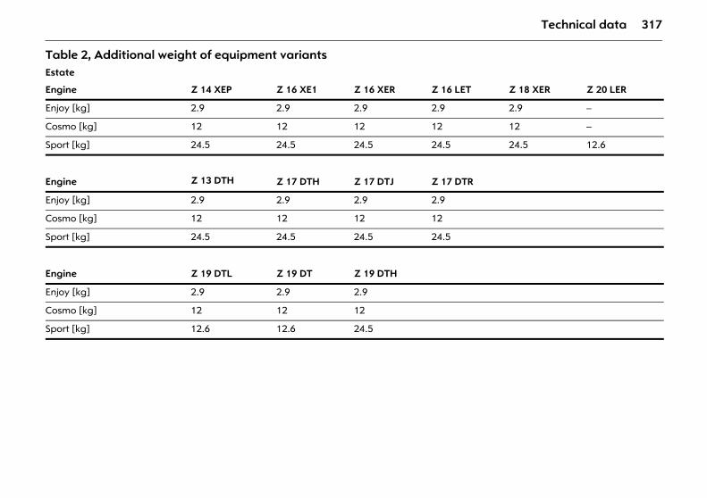
317Technical data
Table 2, Additional weight of equipment variants Estate
Engine Z 14 XEP Z 16 XE1 Z 16 XER Z 16 LET Z 18 XER Z 20 LER
Enjoy [kg] 2.9 2.9 2.9 2.9 2.9 –
Cosmo [kg] 12 12 12 12 12 –
Sport [kg] 24.5 24.5 24.5 24.5 24.5 12.6
Engine Z 13 DTH Z 17 DTH Z 17 DTJ Z 17 DTR
Enjoy [kg] 2.9 2.9 2.9 2.9
Cosmo [kg] 12 12 12 12
Sport [kg] 24.5 24.5 24.5 24.5
Engine Z 19 DTL Z 19 DT Z 19 DTH
Enjoy [kg] 2.9 2.9 2.9
Cosmo [kg] 12 12 12
Sport [kg] 12.6 12.6 24.5
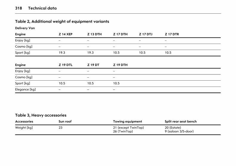
318 Technical data
Table 2, Additional weight of equipment variants
Delivery Van
Engine Z 14 XEP Z 13 DTH Z 17 DTH Z 17 DTJ Z 17 DTR
Enjoy [kg] – – – – –
Cosmo [kg] – – – – –
Sport [kg] 19.3 19.3 10.5 10.5 10.5
Engine Z 19 DTL Z 19 DT Z 19 DTH
Enjoy [kg] – – –
Cosmo [kg] – – –
Sport [kg] 10.5 10.5 10.5
Elegance [kg] – – –
Table 3, Heavy accessoriesAccessories Sun roof Towing equipment Split rear seat bench
Weight [kg] 23 21 (except TwinTop)26 (TwinTop)
20 (Estate)9 (saloon 3/5-door)
319Technical data
Tyres Not all tyres available on the market currently meet the structural requirements. We recommend that you consult an Opel Partner concerning suitable tyre makes.
These tyres have undergone special tests to establish their reliability, safety and specific suitability for Opel vehicles. Despite continuous market monitoring, we are unable to assess these attributes for other tyres, even if they have been granted approval by the relevant authorities or in some other form.
Additional information 3 212.
Winter tyres 3 Tyres of size 215/45 R 17, 225/45 R 17, 225/40 R 18 and 235/35 R 19 are not to be used as winter tyres.
Saloon, Estate, Delivery Van: tyres of size 215/45 R 17 are only approved as winter tyres if the vehicle was equipped with 18-inch wheels in the factory.
If you use winter tyres 3, the spare wheel may still be fitted with a summer tyre. If you use the spare wheel the vehicle’s handling may be altered. Obtain a replacement for the faulty tyre as soon as possible, and have the wheel balanced and fitted to the vehicle.
Winter tyres are permitted on the Astra OPC only on special Opel-approved alloy wheels.
Additional information 3 217.
Tyre chains 3 Tyre chains may be used on the front wheels only.
We recommend the use of fine-link snow chains which amount to max 10 mm on the tread and tyre inner wall with chain lock.
Tyre chains are not permitted on the emergency wheel 115/70 R 16 and on tyres of size 225/45 R 17, 225/40 R 18 and 235/35 R 19.
Saloon, Estate, Delivery Van: tyre chains are only approved on tyres of size 215/45 R 17 if the vehicle was equipped with 18-inch wheels in the factory.
Additional information 3 218.
Wheels Wheel bolt tightening torque: 110 Nm.
Spare wheel 3 Depending on the version, the spare wheel may take the form of a temporary spare wheel 3: vehicle driveability may be altered by use of the spare wheel. Obtain a replacement for the faulty tyre as soon as possible, and have the wheel balanced and fitted to the vehicle.
On vehicles with alloy wheels 3 the spare wheel may have a steel rim.
The spare wheel may be fitted with a smaller tyre1) and smaller wheel than the wheels fitted to the vehicle.
Tyre pressure (overpressure) The specified tyre pressures are valid for cold tyres. The increased tyre pressure resulting from extensive driving must not be reduced. The tyre pressures specified on the following pages apply to both summer and winter tyres.
Always inflate the spare wheel 3 to the tyre pressure for full load - see tables on following pages.
Temporary spare wheel 3 tyre pressure - see tables on next page.
In vehicles with tyre pressure monitoring system 3 there is an adapter in the valve cap key. Screw adapter to valve before attaching tyre pressure gauge, 3 213.
Additional notes 3 212 to 3 218.
1) Country-specific version: The spare wheel is only to be used as a temporary spare wheel.
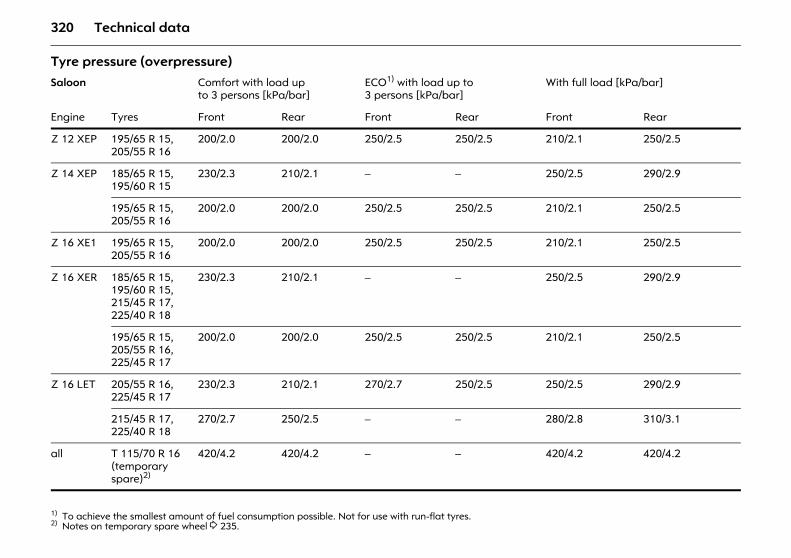
320 Technical data
Tyre pressure (overpressure) Saloon Comfort with load up
to 3 persons [kPa/bar]ECO1) with load up to 3 persons [kPa/bar]
1) To achieve the smallest amount of fuel consumption possible. Not for use with run-flat tyres.
With full load [kPa/bar]
Engine Tyres Front Rear Front Rear Front Rear
Z 12 XEP 195/65 R 15,205/55 R 16
200/2.0 200/2.0 250/2.5 250/2.5 210/2.1 250/2.5
Z 14 XEP 185/65 R 15,195/60 R 15
230/2.3 210/2.1 – – 250/2.5 290/2.9
195/65 R 15,205/55 R 16
200/2.0 200/2.0 250/2.5 250/2.5 210/2.1 250/2.5
Z 16 XE1 195/65 R 15,205/55 R 16
200/2.0 200/2.0 250/2.5 250/2.5 210/2.1 250/2.5
Z 16 XER 185/65 R 15,195/60 R 15,215/45 R 17,225/40 R 18
230/2.3 210/2.1 – – 250/2.5 290/2.9
195/65 R 15,205/55 R 16,225/45 R 17
200/2.0 200/2.0 250/2.5 250/2.5 210/2.1 250/2.5
Z 16 LET 205/55 R 16,225/45 R 17
230/2.3 210/2.1 270/2.7 250/2.5 250/2.5 290/2.9
215/45 R 17,225/40 R 18
270/2.7 250/2.5 – – 280/2.8 310/3.1
all T 115/70 R 16 (temporary spare)2)
2) Notes on temporary spare wheel 3 235.
420/4.2 420/4.2 – – 420/4.2 420/4.2
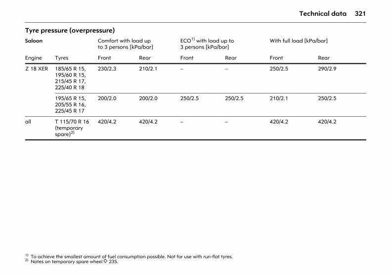
321Technical data
Tyre pressure (overpressure) Saloon Comfort with load up
to 3 persons [kPa/bar]ECO1) with load up to 3 persons [kPa/bar]
1) To achieve the smallest amount of fuel consumption possible. Not for use with run-flat tyres.
With full load [kPa/bar]
Engine Tyres Front Rear Front Rear Front Rear
Z 18 XER 185/65 R 15,195/60 R 15,215/45 R 17,225/40 R 18
230/2.3 210/2.1 – – 250/2.5 290/2.9
195/65 R 15,205/55 R 16,225/45 R 17
200/2.0 200/2.0 250/2.5 250/2.5 210/2.1 250/2.5
all T 115/70 R 16 (temporary spare)2)
2) Notes on temporary spare wheel 3 235.
420/4.2 420/4.2 – – 420/4.2 420/4.2
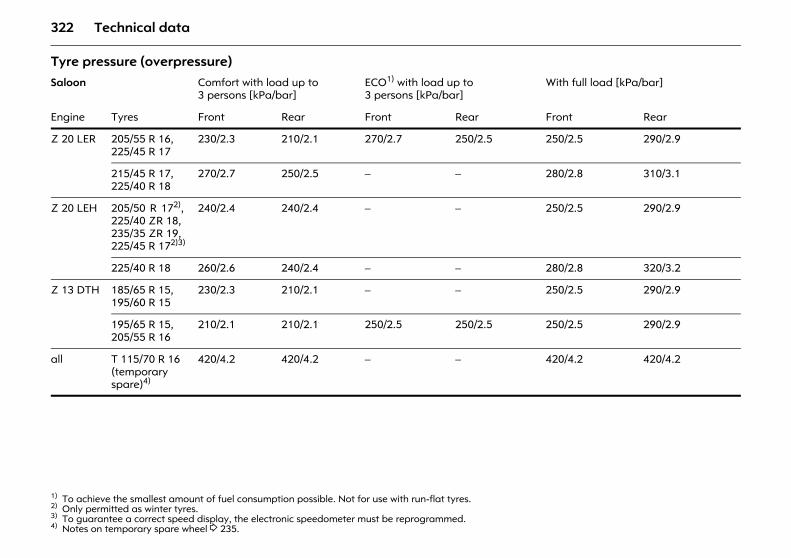
322 Technical data
Tyre pressure (overpressure) Saloon Comfort with load up to
3 persons [kPa/bar]ECO1) with load up to 3 persons [kPa/bar]
1) To achieve the smallest amount of fuel consumption possible. Not for use with run-flat tyres.
With full load [kPa/bar]
Engine Tyres Front Rear Front Rear Front Rear
Z 20 LER 205/55 R 16,225/45 R 17
230/2.3 210/2.1 270/2.7 250/2.5 250/2.5 290/2.9
215/45 R 17,225/40 R 18
270/2.7 250/2.5 – – 280/2.8 310/3.1
Z 20 LEH 205/50 R 172),225/40 ZR 18,235/35 ZR 19,225/45 R 172)3)
2) Only permitted as winter tyres. 3) To guarantee a correct speed display, the electronic speedometer must be reprogrammed.
240/2.4 240/2.4 – – 250/2.5 290/2.9
225/40 R 18 260/2.6 240/2.4 – – 280/2.8 320/3.2
Z 13 DTH 185/65 R 15,195/60 R 15
230/2.3 210/2.1 – – 250/2.5 290/2.9
195/65 R 15,205/55 R 16
210/2.1 210/2.1 250/2.5 250/2.5 250/2.5 290/2.9
all T 115/70 R 16 (temporary spare)4)
4) Notes on temporary spare wheel 3 235.
420/4.2 420/4.2 – – 420/4.2 420/4.2
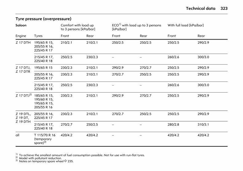
323Technical data
Tyre pressure (overpressure) Saloon Comfort with load up
to 3 persons [kPa/bar]ECO1) with load up to 3 persons [kPa/bar]
1) To achieve the smallest amount of fuel consumption possible. Not for use with run-flat tyres.
With full load [kPa/bar]
Engine Tyres Front Rear Front Rear Front Rear
Z 17 DTH 195/65 R 15,205/55 R 16,225/45 R 17
210/2.1 210/2.1 250/2.5 250/2.5 250/2.5 290/2.9
215/45 R 17,225/40 R 18
250/2.5 230/2.3 – – 260/2.6 300/3.0
Z 17 DTJ, Z 17 DTR
195/65 R 15 230/2.3 210/2.1 290/2.9 270/2.7 250/2.5 290/2.9
205/55 R 16,225/45 R 17
230/2.3 210/2.1 270/2.7 250/2.5 250/2.5 290/2.9
215/45 R 17,225/40 R 18
250/2.5 230/2.3 – – 260/2.6 300/3.0
Z 17 DTJ2)
2) Model with pollutant reduction.
185/65 R 15,195/60 R 15,195/65 R 15,205/55 R 16
230/2.3 210/2.1 290/2.9 270/2.7 250/2.5 290/2.9
Z 19 DTL,Z 19 DT,Z 19 DTH
205/55 R 16,225/45 R 17
230/2.3 210/2.1 270/2.7 250/2.5 250/2.5 290/2.9
215/45 R 17,225/40 R 18
270/2.7 250/2.5 – – 280/2.8 310/3.1
all T 115/70 R 16 (temporary spare)3)
3) Notes on temporary spare wheel 3 235.
420/4.2 420/4.2 – – 420/4.2 420/4.2
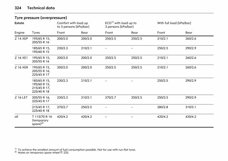
324 Technical data
Tyre pressure (overpressure) Estate Comfort with load up
to 3 persons [kPa/bar]ECO1) with load up to 3 persons [kPa/bar]
1) To achieve the smallest amount of fuel consumption possible. Not for use with run-flat tyres.
With full load [kPa/bar]
Engine Tyres Front Rear Front Rear Front Rear
Z 14 XEP 195/65 R 15,205/55 R 16
200/2.0 200/2.0 250/2.5 250/2.5 210/2.1 260/2.6
185/65 R 15,195/60 R 15
230/2.3 210/2.1 – – 250/2.5 290/2.9
Z 16 XE1 195/65 R 15,205/55 R 16
200/2.0 200/2.0 250/2.5 250/2.5 210/2.1 260/2.6
Z 16 XER 195/65 R 15,205/55 R 16,225/45 R 17
200/2.0 200/2.0 250/2.5 250/2.5 210/2.1 260/2.6
185/65 R 15,195/60 R 15,215/45 R 17,225/40 R 18
230/2.3 210/2.1 – – 250/2.5 290/2.9
Z 16 LET 205/55 R 16,225/45 R 17
230/2.3 210/2.1 270/2.7 250/2.5 250/2.5 290/2.9
215/45 R 17,225/40 R 18
270/2.7 250/2.5 – – 280/2.8 310/3.1
all T 115/70 R 16 (temporary spare)2)
2) Notes on temporary spare wheel 3 235.
420/4.2 420/4.2 – – 420/4.2 420/4.2
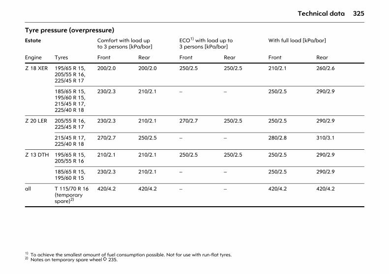
325Technical data
Tyre pressure (overpressure) Estate Comfort with load up
to 3 persons [kPa/bar]ECO1) with load up to 3 persons [kPa/bar]
1) To achieve the smallest amount of fuel consumption possible. Not for use with run-flat tyres.
With full load [kPa/bar]
Engine Tyres Front Rear Front Rear Front Rear
Z 18 XER 195/65 R 15,205/55 R 16,225/45 R 17
200/2.0 200/2.0 250/2.5 250/2.5 210/2.1 260/2.6
185/65 R 15,195/60 R 15,215/45 R 17,225/40 R 18
230/2.3 210/2.1 – – 250/2.5 290/2.9
Z 20 LER 205/55 R 16,225/45 R 17
230/2.3 210/2.1 270/2.7 250/2.5 250/2.5 290/2.9
215/45 R 17,225/40 R 18
270/2.7 250/2.5 – – 280/2.8 310/3.1
Z 13 DTH 195/65 R 15,205/55 R 16
210/2.1 210/2.1 250/2.5 250/2.5 250/2.5 290/2.9
185/65 R 15,195/60 R 15
230/2.3 210/2.1 – – 250/2.5 290/2.9
all T 115/70 R 16 (temporary spare)2)
2) Notes on temporary spare wheel 3 235.
420/4.2 420/4.2 – – 420/4.2 420/4.2
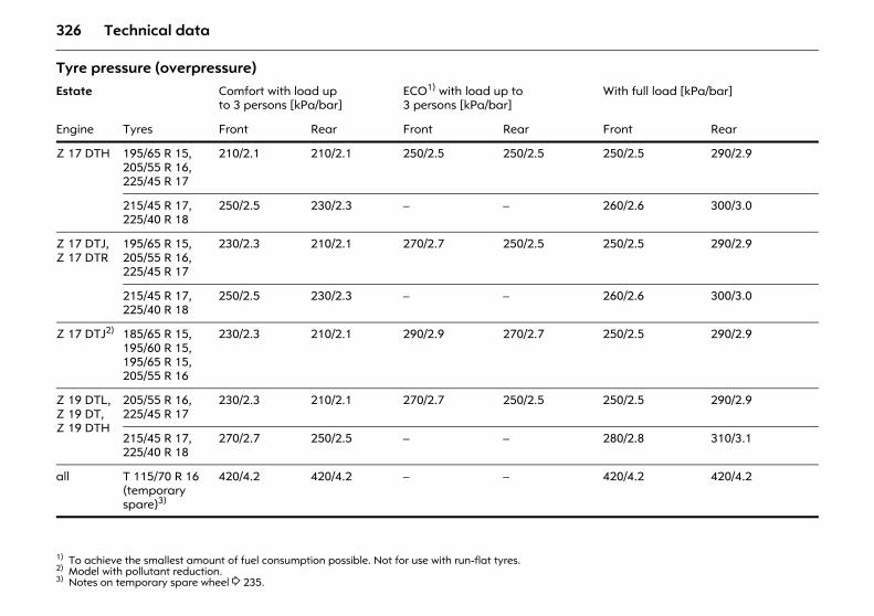
326 Technical data
Tyre pressure (overpressure) Estate Comfort with load up
to 3 persons [kPa/bar]ECO1) with load up to 3 persons [kPa/bar]
1) To achieve the smallest amount of fuel consumption possible. Not for use with run-flat tyres.
With full load [kPa/bar]
Engine Tyres Front Rear Front Rear Front Rear
Z 17 DTH 195/65 R 15,205/55 R 16,225/45 R 17
210/2.1 210/2.1 250/2.5 250/2.5 250/2.5 290/2.9
215/45 R 17,225/40 R 18
250/2.5 230/2.3 – – 260/2.6 300/3.0
Z 17 DTJ, Z 17 DTR
195/65 R 15,205/55 R 16,225/45 R 17
230/2.3 210/2.1 270/2.7 250/2.5 250/2.5 290/2.9
215/45 R 17,225/40 R 18
250/2.5 230/2.3 – – 260/2.6 300/3.0
Z 17 DTJ2)
2) Model with pollutant reduction.
185/65 R 15,195/60 R 15,195/65 R 15,205/55 R 16
230/2.3 210/2.1 290/2.9 270/2.7 250/2.5 290/2.9
Z 19 DTL,Z 19 DT,Z 19 DTH
205/55 R 16,225/45 R 17
230/2.3 210/2.1 270/2.7 250/2.5 250/2.5 290/2.9
215/45 R 17,225/40 R 18
270/2.7 250/2.5 – – 280/2.8 310/3.1
all T 115/70 R 16 (temporary spare)3)
3) Notes on temporary spare wheel 3 235.
420/4.2 420/4.2 – – 420/4.2 420/4.2
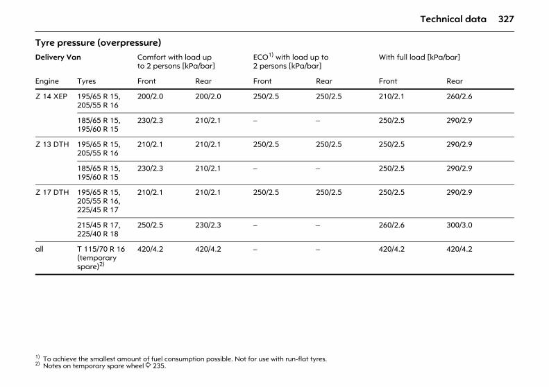
327Technical data
Tyre pressure (overpressure) Delivery Van Comfort with load up
to 2 persons [kPa/bar]ECO1) with load up to 2 persons [kPa/bar]
1) To achieve the smallest amount of fuel consumption possible. Not for use with run-flat tyres.
With full load [kPa/bar]
Engine Tyres Front Rear Front Rear Front Rear
Z 14 XEP 195/65 R 15,205/55 R 16
200/2.0 200/2.0 250/2.5 250/2.5 210/2.1 260/2.6
185/65 R 15,195/60 R 15
230/2.3 210/2.1 – – 250/2.5 290/2.9
Z 13 DTH 195/65 R 15,205/55 R 16
210/2.1 210/2.1 250/2.5 250/2.5 250/2.5 290/2.9
185/65 R 15,195/60 R 15
230/2.3 210/2.1 – – 250/2.5 290/2.9
Z 17 DTH 195/65 R 15,205/55 R 16,225/45 R 17
210/2.1 210/2.1 250/2.5 250/2.5 250/2.5 290/2.9
215/45 R 17,225/40 R 18
250/2.5 230/2.3 – – 260/2.6 300/3.0
all T 115/70 R 16 (temporary spare)2)
2) Notes on temporary spare wheel 3 235.
420/4.2 420/4.2 – – 420/4.2 420/4.2
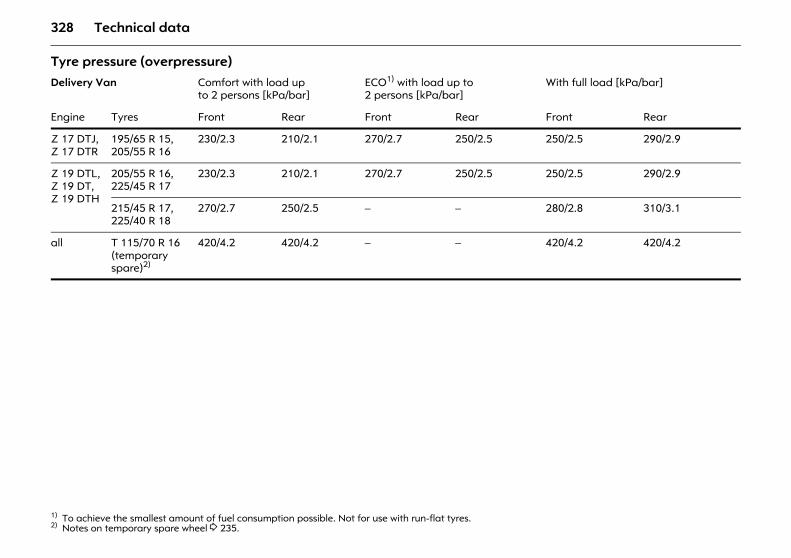
328 Technical data
Tyre pressure (overpressure) Delivery Van Comfort with load up
to 2 persons [kPa/bar]ECO1) with load up to 2 persons [kPa/bar]
1) To achieve the smallest amount of fuel consumption possible. Not for use with run-flat tyres.
With full load [kPa/bar]
Engine Tyres Front Rear Front Rear Front Rear
Z 17 DTJ, Z 17 DTR
195/65 R 15,205/55 R 16
230/2.3 210/2.1 270/2.7 250/2.5 250/2.5 290/2.9
Z 19 DTL,Z 19 DT,Z 19 DTH
205/55 R 16,225/45 R 17
230/2.3 210/2.1 270/2.7 250/2.5 250/2.5 290/2.9
215/45 R 17,225/40 R 18
270/2.7 250/2.5 – – 280/2.8 310/3.1
all T 115/70 R 16 (temporary spare)2)
2) Notes on temporary spare wheel 3 235.
420/4.2 420/4.2 – – 420/4.2 420/4.2
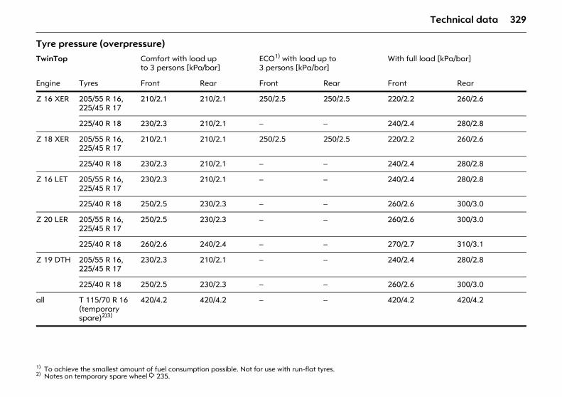
329Technical data
Tyre pressure (overpressure) TwinTop Comfort with load up
to 3 persons [kPa/bar]ECO1) with load up to 3 persons [kPa/bar]
1) To achieve the smallest amount of fuel consumption possible. Not for use with run-flat tyres.
With full load [kPa/bar]
Engine Tyres Front Rear Front Rear Front Rear
Z 16 XER 205/55 R 16,225/45 R 17
210/2.1 210/2.1 250/2.5 250/2.5 220/2.2 260/2.6
225/40 R 18 230/2.3 210/2.1 – – 240/2.4 280/2.8
Z 18 XER 205/55 R 16,225/45 R 17
210/2.1 210/2.1 250/2.5 250/2.5 220/2.2 260/2.6
225/40 R 18 230/2.3 210/2.1 – – 240/2.4 280/2.8
Z 16 LET 205/55 R 16,225/45 R 17
230/2.3 210/2.1 – – 240/2.4 280/2.8
225/40 R 18 250/2.5 230/2.3 – – 260/2.6 300/3.0
Z 20 LER 205/55 R 16,225/45 R 17
250/2.5 230/2.3 – – 260/2.6 300/3.0
225/40 R 18 260/2.6 240/2.4 – – 270/2.7 310/3.1
Z 19 DTH 205/55 R 16,225/45 R 17
230/2.3 210/2.1 – – 240/2.4 280/2.8
225/40 R 18 250/2.5 230/2.3 – – 260/2.6 300/3.0
all T 115/70 R 16(temporary spare)2)3)
2) Notes on temporary spare wheel 3 235.
420/4.2 420/4.2 – – 420/4.2 420/4.2
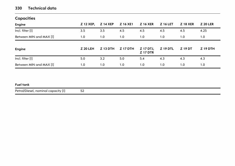
330 Technical data
Capacities Engine Z 12 XEP, Z 14 XEP Z 16 XE1 Z 16 XER Z 16 LET Z 18 XER Z 20 LER
Incl. filter [l] 3.5 3.5 4.5 4.5 4.5 4.5 4.25
Between MIN and MAX [l] 1.0 1.0 1.0 1.0 1.0 1.0 1.0
Engine Z 20 LEH Z 13 DTH Z 17 DTH Z 17 DTJ, Z 17 DTR
Z 19 DTL Z 19 DT Z 19 DTH
Incl. filter [l] 5.0 3.2 5.0 5.4 4.3 4.3 4.3
Between MIN and MAX [l] 1.0 1.0 1.0 1.0 1.0 1.0 1.0
Fuel tank
Petrol/Diesel, nominal capacity [l] 52
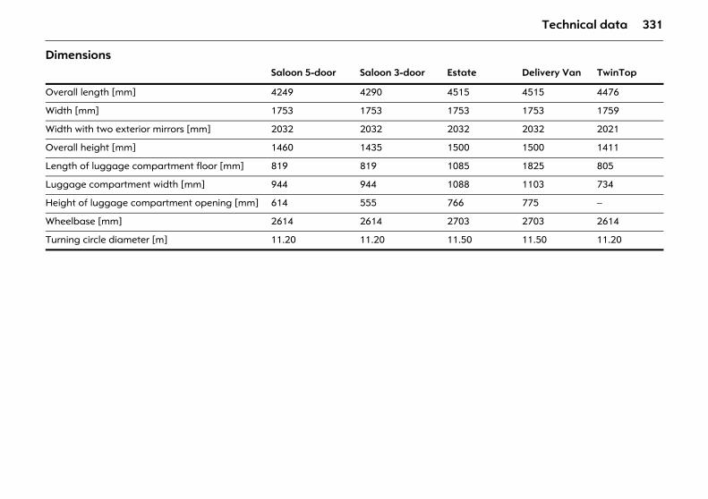
331Technical data
Dimensions Saloon 5-door Saloon 3-door Estate Delivery Van TwinTop
Overall length [mm] 4249 4290 4515 4515 4476
Width [mm] 1753 1753 1753 1753 1759
Width with two exterior mirrors [mm] 2032 2032 2032 2032 2021
Overall height [mm] 1460 1435 1500 1500 1411
Length of luggage compartment floor [mm] 819 819 1085 1825 805
Luggage compartment width [mm] 944 944 1088 1103 734
Height of luggage compartment opening [mm] 614 555 766 775 –
Wheelbase [mm] 2614 2614 2703 2703 2614
Turning circle diameter [m] 11.20 11.20 11.50 11.50 11.20
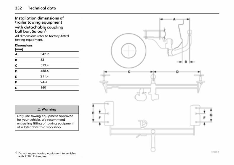
332 Technical data
Installation dimensions of trailer towing equipment with detachable coupling ball bar, Saloon1) All dimensions refer to factory-fitted towing equipment.
1) Do not mount towing equipment to vehicles with Z 20 LEH engine.
Dimensions [mm]A 342.9
B 83
C 513.4
D 488.6
E 211.4
F 94.3
G 160
9 Warning
Only use towing equipment approved for your vehicle. We recommend entrusting fitting of towing equipment at a later date to a workshop.
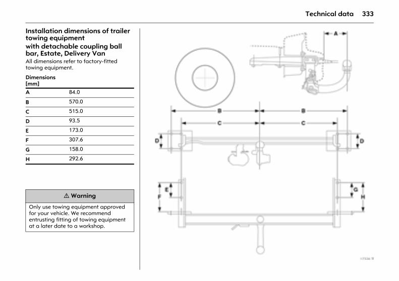
333Technical data
Installation dimensions of trailer towing equipment with detachable coupling ball bar, Estate, Delivery Van All dimensions refer to factory-fitted towing equipment.
Dimensions [mm]A 84.0
B 570.0
C 515.0
D 93.5
E 173.0
F 307.6
G 158.0
H 292.6
9 Warning
Only use towing equipment approved for your vehicle. We recommend entrusting fitting of towing equipment at a later date to a workshop.
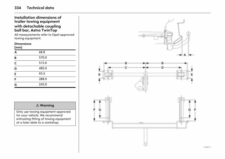
334 Technical data
Installation dimensions of trailer towing equipment with detachable coupling ball bar, Astra TwinTop All measurements refer to Opel-approved towing equipment.
Dimensions [mm]A 68.8
B 570.0
C 515.0
D 485.0
E 93.5
F 288.0
G 245.0
9 Warning
Only use towing equipment approved for your vehicle. We recommend entrusting fitting of towing equipment at a later date to a workshop.
335Customer information
Customer information Recording and protection of vehicle data Event data recorderThe vehicle has a range of highly developed systems which monitor and control various items of vehicle data. Some data is stored during normal vehicle operation in order to detect faults and facilitate any repairs necessary, while other data is stored by the event data recorder (EDR) only in the event of an accident or near-accident.
The systems can store data on the state of the vehicle and how it was being operated (e.g. vehicle speed, use of brakes, wearing of seatbelts). To read off this data, special devices and access to the vehicle are necessary. This takes place in a workshop during maintenance. During this, some data is transferred to the global GM diagnostics system.
The manufacturer does not call up any data on an accident or pass on such data to others, except:
z with the consent of the vehicle owner or - in the case of leased vehicles - with the consent of the lessee,
z when requested to do so by the police or similar state organisations,
z as part of the defence in the event of a legal case being brought against the manufacturer,
z prescribed by legislation.
In addition, for the data collected and received, the manufacturer may:
z use it for the manufacturer’s research purposes,
z make it available for research purposes, if adequate confidentiality is assured and its use is necessary,
z use summaries jointly with other organisations for research purposes which are not linked with any specific vehicle.
Recording and protection of vehicle data.................................................... 335
336 Index
Index AABS (Anti-lock Braking System) ........... 211Accessories ....................................... 88, 232Accessory socket ................................... 104Active head restraints ....................... 21, 69Adaptive Forward Lighting (AFL) ........ 142
Bulb replacement .............................. 257Driving abroad ................................... 146
Air conditioning system ................150, 156Air intake ................................................ 169Air quality sensor ................................... 164Air recirculation system .........156, 160, 168Air vents ................................................. 152Airbags ..................................................... 91Alarm system ........................................... 44Alternator ............................................... 111Antenna .................................135, 147, 271Antifreeze ............................................... 287Antifreeze protection ....................287, 290Anti-knock quality of fuel
Octane number .................................. 294Anti-theft alarm system .......................... 44
Anti-theft locking system ........................ 39Towing equipment ............................ 222
Anti-theft protection ............................... 18Aquaplaning .......................................... 216Armrest ...................................... 70, 71, 106Ashtray ........................................... 105, 146Automatic
Anti-dazzle interior mirror .................. 49Automatic air recirculation mode ...................... 164, 168
Automatic transmission .......................... 16Automatic mode ....................... 179, 183Control indicator ........................ 180, 185Driving programme ................... 180, 185Fault ........................................... 182, 187Interruption of power supply .... 182, 187Kickdown .................................... 181, 186Manual mode .................................... 184Selector lever ...............16, 179, 183, 184Winter programme .................... 180, 185
Automatic wiping .................................. 136AUX input .............................................. 148
337Index
BBattery ............................................189, 290
Interruption of power supply .......... 53, 176, 182, 187
Battery discharge protection ................ 146Before starting off ................................... 16Belt force limiters ..................................... 85Belt tensioners .......................................... 85Bleeding, diesel fuel system .................. 226Board information display .................... 118Bonnet .................................................... 226Boot, see Luggage compartment ....42, 71Brake assist ............................................ 212Brake lamp ............................................. 211Brake system .......................................... 210Brakes
ABS ...................................................... 211Brake assist ........................................ 212Brake fluid .......................................... 288Brake lamps ...............................260, 265Brake servo unit ................................. 188Foot brake .......................................... 212Hand brake ........................................ 212
Bulb replacement ..........................251, 253Bulbs ...............................................251, 253
CCar Pass ................................................... 28Caravan/trailer towing .......................... 188Cargo box ................................................ 80Catalytic converter ................................ 197CDC (Continuous Damping Control) .........................................111, 200
Central locking system ............................ 38Changing the battery
Remote control .................................... 32Changing tyre/wheel type .................... 212Changing wheels ................................... 237Chassis number, see vehicle identification number ...... 293
Check control ................................... 22, 133Child restraint system .............................. 88Child safety locks ............................... 47, 51Cigarette lighter ............................103, 146Climate control ...................................... 150Climate control system .................151, 163Clock ....................................................... 116Clutch operation ............................178, 189CO2 emissions ........................................ 302Cold start ............................................... 189Colour information display ................... 118Continuous Damping Control ............... 200Continuous Damping Control (CDC) ...............................111, 200
Contrast .................................................. 129
Control indicatorABS (Anti-lock Braking System) ....... 211Airbag .......................................... 95, 102Engine electronics .............................. 195Exhaust ............................................... 195Immobiliser ........................................... 29Park pilot ............................................ 205Transmission .............................. 180, 185Tyre pressure monitoring system ..................... 208, 209
Control indicators ............................ 12, 109Adaptive Forward Lighting (AFL) ............................ 114, 142Belt tensioners ..................................... 86Brake system ...................................... 210Cruise control ..................................... 202DDS ..................................................... 206Deflation detection system ............... 206ESP (Electronic Stability Program) .... 198IDS+ ............................................. 200, 201
Coolant .................................................. 287Coolant level .......................................... 288Coolant temperature ............................ 111Cooling ........................................... 157, 162Correcting time .............................. 122, 127Coupling socket load ............................ 224Courtesy lamp ....................................... 144Courtesy lamps
Bulb replacement .............................. 270Cruise control ......................................... 202Curtain airbags ....................................... 94Curve lighting ........................................ 142
338 Index
DDashboard, see Instrument panel ............ 6Data ..................................................28, 292Date ........................................................ 120Daytime running lights .......................... 138Decommissioning .................................. 291Deflation detection system ................... 206Deflation Detection System (DDS) .................................24, 206
Demisting and defrostingWindows ............................................. 155With climate control system .............. 165With the air conditioning system .........................................158, 162
Diesel fuel filter ...................................... 287Diesel fuel system ..........................226, 287Diesel particle filter ........... 27, 52, 114, 189Dimensions ............................................. 331Dipped beam ............................................. 7
Bulb replacement .......................254, 257Display ............................................117, 118Door handle lighting ............................. 145Door locks .........................................28, 273Doors ...................................................... 111Driving abroad
Headlamps ......................................... 146Driving hints ........................................... 188
EEasy Load ................................................ 81Easytronic ................................................. 15
Driving programmes ......................... 173Fault .................................................... 176Interruption of power supply ............ 176Kickdown ............................................ 174Selector lever ........................................ 15Starting off ......................................... 172Winter programme ............................ 174
Economical driving ................................ 190Electric sun roof ....................................... 54Electrical system .................................... 291Electro-hydraulic power assisted steering .................................. 188
Electronic components .......................... 291Electronic immobiliser ............................. 29Electronic Stability Program ................. 198Engine code .......... 293, 294, 295, 296, 297Engine control indicator ........................ 195Engine oil ........................................282, 285
Additives ............................................ 282Filling .................................................. 282Viscosity .............................................. 282
Engine oil consumption ......................... 188Engine oil level ...............................112, 285Engine oil pressure ................................ 109Engine speed ......................................... 189Engine wash ........................................... 273Entry lighting .......................................... 145ESP (Electronic Stability Program) ........ 198Event data recorder .............................. 335Exhaust control indicator ...................... 195
Exhaust gases ........................................ 196Exhaust system ...................................... 188Exterior lights delayed switch-off ........ 143Exterior mirrors ....................5, 6, 47, 49, 52
FFan ......................................................... 153Filling station
Engine oil level ................................... 285Fuel .............................294, 295, 296, 297Opening the bonnet .......................... 226Tyre pressure ............................. 191, 319Vehicle data ....................................... 292Windscreen washer system .............. 290
First-aid kit (cushion) ............................ 232Flat tyre .................................................. 240FlexOrganizer .......................................... 79Fog lamps .............................................. 140
Bulb replacement .............................. 260Fog tail lamp ......................................... 140
Bulb replacement ...................... 260, 265Folding roof, see TwinTop ...................... 56Folding the backrest ............................... 66Foot brake ............................................. 212Front passenger airbag .......................... 91Fuel ........................ 192, 294, 295, 296, 297Fuel consumption ..................190, 192, 302Fuel filler cap ......................................... 192Fuel filter ................................................ 287Fuel gauge ............................................. 115Fuel level ................................................ 115Fuel system, diesel ................................ 226Fuse extractor ........................................ 245Fuses ...................................................... 244
339Index
GGears ................................................15, 178Generator, see Alternator ..................... 111Genuine Opel parts and accessories ... 284Glasses compartment ........................... 107Glove compartment .............................. 106Glove compartment lighting ................. 145
Bulb replacement ............................... 270Graphical information display .............. 118Gross vehicle weight .............................. 311Gross vehicle weight rating ................... 311
HHalogen headlamp system .................. 253
Bulb replacement ............................... 253Driving abroad ................................... 146
Hand brake ......................................18, 212Hazard warning lamps .....................7, 141Head restraints ..................................21, 69Headlamp flash ..................................... 139Headlamp range adjustment ............... 141Headlamp switch .......................6, 138, 139Headlamp washer system ......13, 137, 290Headlamps ................................................. 6
Daytime running lights ...................... 138Driving abroad ................................... 146Fog lamps ........................................... 140Reversing lamps ................................. 140Warning device .................................. 135
Heated exterior mirrors ...............14, 49, 52Heated front seats .................................. 68Heated rear window ...................14, 49, 52Heater .................................................... 169Heating ..........................................150, 154
Seats ..................................................... 68With climate control system ............. 164With the air conditioning system .........................................158, 162
Height adjustmentSeat belts .............................................. 87Steering wheel ........................................ 6
High-pressure cleaners .................272, 273Hill Start Assist ....................................... 212Horn .......................................................... 13
IIdentification plate ................................ 292Idling ....................................................... 178IDS+ (Interactive Driving System) .........................................198, 200
Ignition logic ..................................122, 129Ignition system .......................284, 290, 291Immobiliser ............................................... 29Information display ............................... 118Infotainment system ............................. 147Inspection system .................................. 283Instrument display ................................. 115Instrument illumination ......................... 144
Bulb replacement .............................. 270
Instrument panel ........................................6Instruments ............................................ 108Interactive Driving System (IDS+).. 198, 200Interior mirror ....................................... 5, 49Interruption of power supply .......... 53, 134
Easytronic ........................................... 176Electric windows .................................. 53Selector lever lock ...................... 182, 187
ISOFIX ...................................................... 90
JJack ................................................ 236, 238Jump leads ............................................. 227
KKey
Extending ............................................. 28Locking doors ...................................... 38Remove ................................................ 18Starting the engine .............................. 17
Keys .......................................................... 28
340 Index
LLanguage selection .......................122, 128Lashing eyes ............................................ 79Level control system .............................. 205Light switch ................................................ 6Lighting ......................................6, 112, 138
Driving abroad ................................... 146Loading ......................... 223, 307, 308, 310Locking doors .......................................... 38Locking from the inside ........................... 40Locks ....................................................... 273Lubricants .............................................. 285Luggage compartment
Bulb replacement ............................... 270FlexOrganizer ....................................... 79Lighting .............................................. 145Loading ................................83, 223, 311Locking ................................................. 42Safety net .......................................77, 78
Luggage compartment cover ..........75, 76Lumbar support ....................................... 66
MMain beam ......................................... 7, 139
Bulb replacement ......................255, 257Control indicator ................................ 113
MaintenanceAir conditioning system ..................... 169Antifreeze protection ........................ 287Brake fluid .......................................... 288Brakes ................................................. 288Catalytic converter ............................ 197Engine oil ............................................ 285Fuel consumption .............................. 191Tyre pressure ...................................... 213Tyres ................................................... 215
Manual transmission, see Transmission ........................... 15, 178
Mirrors ............................................ 5, 47, 49Misted windows .............................155, 165Mobile telephone ................................... 148Motorway lighting ................................. 142Muffler, see Exhaust system ................. 196
NNeutral, transmission .............................. 15Number plate lamps
Bulb replacement .............................. 269Number plate lighting ........................... 269Number plates ....................................... 291
OOctane numbers .................................... 294Oil ........................................................... 282
Additives ............................................ 282Filling .................................................. 282Viscosity ............................................. 282
Oil consumption .................................... 285Oil level ................................................... 285Oil pressure ............................................ 109Oils .......................................................... 285Opel Service ........................................... 274Open&Start system .............18, 23, 32, 108Operating temperature ........................ 189Outside temperature gauge ................ 119Overrun .......................................... 189, 191
PPaintwork damage ............................... 272Panoramic windscreen ................ 25, 48, 53Park pilot ................................................ 204Parking ..................................................... 18Parking lamps .................................... 6, 143
Bulb replacement ...................... 256, 258Parking the vehicle .................................. 18Parts ....................................................... 284Pedals ..................................................... 189Performance .......................................... 302Petrol ..............................294, 295, 296, 297
341Index
Pollen filter ............................................. 169Power assisted steering, see electro-hydraulic power assisted steering .................................. 188
Power steering, see electro-hydraulic power assisted steering ....................... 188
Preheating ........................................18, 114Preheating switch .................................... 18Puddle light ............................................ 145
QQuickheat ............................................... 169
RRadio ..............................................135, 147Radio equipment (CB) ........................... 148Radio reception .............................135, 147Rain sensor ............................................. 136Reading lamps ...............................144, 145Rear lamp cluster ................................... 138
Bulb replacement .......................260, 265Rear screen wiper .................................. 137Rear window washer system .............. 14, 137, 271, 290
Refuelling ................................................ 192Fuel filler cap ...................................... 193
Remote controlCentral locking system ........2, 23, 30, 34Steering wheel ..............................22, 147
Replacement keys ................................... 28Reversing lamps
Bulb replacement ......................260, 265Rollover protection system ..................... 59Roof lining ....................................25, 48, 53Roof load .........84, 188, 191, 307, 308, 310Roof rack ......................... 84, 191, 219, 311Roof racks ....................... 84, 191, 219, 311Run-flat tyres .................................216, 217Running in for the first 1000 km ........... 188Running-in
Brakes ................................................. 288
SSafeguard against unauthorised use ............................. 17, 19
Safety accessories ........................... 88, 232Safety net ........................................... 77, 78Saving energy ........................................ 190Seat adjustment .................................. 3, 64Seat belts ......................................... 87, 272Seat height adjustment .................. 3, 4, 65Seat occupancy recognition ................... 96Seat position ............................................ 67Seats ............................................... 3, 64, 66
Heated .................................................. 68Selector lever ..........................171, 179, 183Selector lever lock ....................16, 179, 183Self-diagnosis .................................... 86, 96
Self-help ................................................. 226Central locking system ........................ 41Electric sun roof ................................... 55Electric windows .................................. 53Information display ........................... 120Remote control .............................. 31, 37
Service interval display ......................... 283Service intervals ..................................... 274
Additional operations ....................... 281Extreme operating conditions .......... 281Main inspection ................................. 274
Service work ........................................... 283Side airbags ............................................. 93Signal system ........................................... 13Spare fuses ............................................ 244Spare keys ................................................ 28Spare wheel ...........................234, 235, 237Speed ............................................. 190, 191
Fuel consumption ...................... 190, 191Speedometer ......................................... 115Sport mode ............................................ 111Sport programme ............................ 23, 200Starting the engine ......................... 29, 171Steam-jet cleaners ........................ 272, 273Steering column lock ......................... 17, 18Steering wheel adjustment ........................6Steering wheel remote control ....... 22, 147Stowage compartments ....................... 106Sun roof .................................................... 54Sun visors .............................25, 48, 53, 145Sunblind ................................................... 54System settings .............................. 121, 127
342 Index
TTables ..................................................... 106Tachometer ............................................ 115Tail lamps ............................................... 138
Bulb replacement .......................260, 265Tailgate .................................................... 42Tank
Fuel gauge ......................................... 115Technical data ....................................... 292Telephone, see Mobile telephone ........ 148Temperature regulation ................153, 164Tempomat, see cruise control .............. 202Temporary spare wheel ................218, 235The first 1000 km ................................... 188Tightening torque ..........................240, 319Tilt angle
Seats .................................................4, 65Time ........................................................ 120Tools ....................................................... 236Towing equipment ................................ 220Towing eye .....................................229, 230Trailer Stability Assist (TSA) .................. 225Transmission display .... 117, 170, 178, 183Transmission, automatic ......................... 16
Automatic mode ........................179, 183Driving programme ...................180, 185Fault ............................................182, 187Interruption of power supply ....182, 187Kickdown ....................................181, 186Selector lever ............... 16, 179, 183, 184Selector lever lock ................................ 16Winter programme ....................180, 185
Transmission, EasytronicDriving programmes ......................... 173Fault .................................................... 176Interruption of power supply ............ 176Kickdown ............................................ 174Selector lever ................................ 15, 172Winter programme ............................ 174
Transmission, manual ..................... 15, 178Tread depth ........................................... 215Trip computer ..........................22, 123, 129Trip odometer ........................................ 116Triple information display ..................... 118TSA (Trailer Stability Assist) .................. 225Turn signal lamps ...................................... 7Turn signals
Bulb replacement ..............259, 260, 265Twin Audio ....................................... 23, 148TwinTop ................................................... 56
Closing the roof ................................... 57Opening the roof ................................. 56Rollover protection .............................. 59Warning buzzers .................................. 58Wind deflector ..................................... 61
Tyre chains .....................................218, 319Tyre condition ........................................ 215Tyre pressure .................. 24, 207, 213, 319Tyre pressure monitoring system ......... 207Tyre repair kit ........................................ 240
UUnits of measure ........................... 123, 128Unleaded fuel ................................ 194, 294
VValve cap key ................................ 214, 319Vehicle care ........................................... 271Vehicle decommissioning ..................... 291Vehicle identification number .............. 293Vehicle keys, see Keys ............................ 28Vehicle recommissioning ...................... 291Vehicle tools .......................................... 236Ventilation .....................150, 154, 161, 167
WWarning buzzers ................................... 135Warning messages ................................ 133Warning triangle ................................... 232Washer fluid reservoir, windscreen washer system ................. 290
Weights ..................................307, 308, 310Wheels .................................................... 212Wheels, tyres .......................................... 212Wind deflector ......................................... 61Windows ................................................... 50
Demisting and defrosting ...........155, 158, 162, 165
Windscreen washer system ............ 13, 137Antifreeze protection ........................ 290Washer fluid reservoir ....................... 290
343Index
Windscreen wipers ...................13, 136, 289Winter mode
Starting-off aid .................................. 174Winter operation
Battery ................................................ 189Coolant, antifreeze ............................ 287Fuel consumption .............................. 191Fuel for diesel engines ....................... 192Heating .............................. 150, 158, 162Locks ................................................... 273Tyre chains .................................218, 319Window demisting and defrosting ... 155Windscreen washer system, antifreeze protection ......................... 290
Winter programme ............... 174, 180, 185Winter tyres ....................................217, 319
XXenon headlamp system ...................... 257
Bulb replacement ............................... 257Driving abroad ................................... 146

344 Index