ba059d/06/en/10.03 proline promass 83 valid as of …€¦ · coriolis mass flow measuring system...
TRANSCRIPT

BA059D/06/en/10.0350098470
Valid as of software version:V 1.06.XX (amplifier)V 1.03.XX (communication)
PROline promass 83Coriolis Mass Flow Measuring System
Operating Instructions
Brief operating instructions PROline Promass 83
2 Endress+Hauser
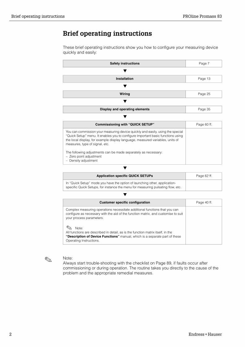
Brief operating instructions
These brief operating instructions show you how to configure your measuring device quickly and easily:
! Note:Always start trouble-shooting with the checklist on Page 89, if faults occur after commissioning or during operation. The routine takes you directly to the cause of the problem and the appropriate remedial measures.
Safety instructions Page 7
Installation Page 13
Wiring Page 25
Display and operating elements Page 35
Commissioning with “QUICK SETUP” Page 60 ff.
You can commission your measuring device quickly and easily, using the special “Quick Setup” menu. It enables you to configure important basic functions using the local display, for example display language, measured variables, units of measures, type of signal, etc.
The following adjustments can be made separately as necessary:– Zero point adjustment– Density adjustment
Application specific QUICK SETUPs Page 62 ff.
In “Quick Setup” mode you have the option of launching other, application-specific Quick Setups, for instance the menu for measuring pulsating flow, etc.
Customer specific configuration Page 40 ff.
Complex measuring operations necessitate additional functions that you can configure as necessary with the aid of the function matrix, and customise to suit your process parameters.
! Note:All functions are described in detail, as is the function matrix itself, in the “Description of Device Functions” manual, which is a separate part of these Operating Instructions.

PROline Promass 83 QUICK SETUP “Commissioning”
Endress+Hauser 3
QUICK SETUP “Commissioning”
! Note:More detailed information on running Quick Setup menus, especially for devices without a local display, can be found on Page 60 ff.
Information on the points numbered in the Quick Setup can be found on the following page.
04200400
6461
0421 6462
6463
6464
4200
4221
4222
4223
4225
4227
4226
4000
4001
4002
4004
4006
4003
4005
4201
4203
4204
4206
4208
4209
4205
4207
0422
646030013001
04040402
2000
1002B++ +E E
- +
ENDRESS+HAUSER
E
ESC
Batching
Yes
Yes
Yes
No
No
No
No
Configure another system unit ?
Current output n Freq./Pulse output n
Selection output type
Automatic configuration of display ?
Carrying out another Quick Setup ?
Quit
AssignCurrent output
Current span
Value 0/4 mA
Value 20 mA
Meas. mode Meas. mode
Meas. mode
Time constant
Time constantFailsafe mode
Failsafe mode
Failsafe mode
AssignFreq. output
End value freq.
Value F Low
Value F High
Output signal
AssignPulse output
Pulse value
Pulse width
Output signal
Operation Mode
Frequency Pulse
Automatic parameterization of the display
Reference Calculated
Fix. Density
Density
UnitRef. Density Exp. Coeff. Lin
Exp. Coeff. SQR
Reference temp.
Volume flow Corr. Vol. flowMass flow Density
Selection system units
Temperature Quit
UnitVolume flow
UnitCorr. Vol. flow
UnitMass flow
UnitDensity
UnitTemperature
UnitTotalizer
Corr. Vol.calculation
UnitTotalizer
Language
Pre-setting
Quick Setup
HOME-POSITION
QSCommission
Pulsating flow Gas measurement
Configure another output ?
Carrying out the selected Quick SetupF06-
83xx
xxxx
-19-
xx-x
x-en
-000

QUICK SETUP “Commissioning” PROline Promass 83
4 Endress+Hauser
! Note:• The display returns to the cell QUICK SETUP COMMISSION (1002) if you press the
ESC key combination during parameter interrogation. The stored parameters remain valid.
• The “Commissioning” Quick Setup must be carried out before one of the Quick Setups explained below is run.
• ➀ Only units not yet configured in the current Setup are offered for selection in eachcycle. The unit for mass, volume and corrected volume is derived from the corresponding flow unit.
• ➁ The “YES” option remains visible until all the units have been configured.“NO” is the only option displayed when no further units are available.
• ➂ Only the outputs not yet configured in the current Setup are offered for selection ineach cycle.
• ➃ The “YES” option remains visible until all the outputs have been parameterized. “NO” is the only option displayed when no further outputs are available.
• ➄ The “automatic parameterization of the display” option contains the following basicsettings/factory settings:YES: Main line = Mass flow; Additional line = Totalizer 1; Information line = Operating/system conditions.NO: The existing (selected) settings remain.

PROline Promass 83 Contents
Endress+Hauser 5
Contents
1 Safety instructions . . . . . . . . . . . . . . . . . 7
1.1 Designated use . . . . . . . . . . . . . . . . . . . . . . . . 71.2 Installation, commissioning and operation . . . 71.3 Operational safety . . . . . . . . . . . . . . . . . . . . . . 71.4 Return . . . . . . . . . . . . . . . . . . . . . . . . . . . . . . . 81.5 Notes on safety conventions and icons . . . . . . 8
2 Identification . . . . . . . . . . . . . . . . . . . . . . 9
2.1 Device designation . . . . . . . . . . . . . . . . . . . . . 92.1.1 Nameplate of the transmitter . . . . . . . 92.1.2 Nameplate of the sensor. . . . . . . . . . 10
2.2 CE mark, declaration of conformity . . . . . . . . 102.3 Registered trademarks . . . . . . . . . . . . . . . . . 11
3 Installation . . . . . . . . . . . . . . . . . . . . . . . . 13
3.1 Incoming acceptance, transport and storage 133.1.1 Incoming acceptance . . . . . . . . . . . 133.1.2 Transport . . . . . . . . . . . . . . . . . . . . . 133.1.3 Storage . . . . . . . . . . . . . . . . . . . . . . . 14
3.2 Installation conditions . . . . . . . . . . . . . . . . . . 143.2.1 Dimensions . . . . . . . . . . . . . . . . . . . 143.2.2 Mounting location . . . . . . . . . . . . . . . 143.2.3 Orientation. . . . . . . . . . . . . . . . . . . . . 163.2.4 Heating . . . . . . . . . . . . . . . . . . . . . . . 183.2.5 Thermal insulation . . . . . . . . . . . . . . 193.2.6 Inlet and outlet runs . . . . . . . . . . . . . 193.2.7 Vibrations . . . . . . . . . . . . . . . . . . . . . 193.2.8 Limiting flow . . . . . . . . . . . . . . . . . . . 19
3.3 Installation instructions . . . . . . . . . . . . . . . . . 203.3.1 Turning the transmitter housing . . . . 203.3.2 Installing the wall-mount transmitter
housing . . . . . . . . . . . . . . . . . . . . . 213.3.3 Turning the local display. . . . . . . . . . 23
3.4 Post installation check . . . . . . . . . . . . . . . . . . 23
4 Wiring . . . . . . . . . . . . . . . . . . . . . . . . . . . . . 25
4.1 Connecting the remote version . . . . . . . . . . . 254.1.1 Connecting the sensor . . . . . . . . . . . 254.1.2 Cable specifications . . . . . . . . . . . . 26
4.2 Connecting the measuring unit . . . . . . . . . . . 274.2.1 Transmitter (aluminium) . . . . . . . . . . 274.2.2 Terminal assignment. . . . . . . . . . . . . 294.2.3 HART connection . . . . . . . . . . . . . . . 31
4.3 Degree of protection . . . . . . . . . . . . . . . . . . . 324.4 Post connection check . . . . . . . . . . . . . . . . . 33
5 Operation . . . . . . . . . . . . . . . . . . . . . . . . . 35
5.1 Display and operating elements . . . . . . . . . . 355.2 Brief operating instructions to the function matrix
405.3 Error messages . . . . . . . . . . . . . . . . . . . . . . . 425.4 Communication (HART) . . . . . . . . . . . . . . . . . 43
5.4.1 Operating options . . . . . . . . . . . . . . . 445.4.2 Device and process variables . . . . . . 455.4.3 Universal / Common practice HART
commands . . . . . . . . . . . . . . . . . . . . . 465.4.4 Device status / Error messages . . . . . 525.4.5 Switching HART write protection on and
off . . . . . . . . . . . . . . . . . . . . . . . . . . . . 57
6 Commissioning . . . . . . . . . . . . . . . . . . . 59
6.1 Function check . . . . . . . . . . . . . . . . . . . . . . . . 596.2 Commissioning . . . . . . . . . . . . . . . . . . . . . . . . 59
6.2.1 Switching on the measuring device . 596.2.2 Quick Setup “Commissioning”. . . . . . 606.2.3 Quick Setup “Pulsating Flow” . . . . . . 626.2.4 Quick Setup “Batching” . . . . . . . . . . 656.2.5 Quick Setup “Gas Measurement” . . . 696.2.6 Zero point adjustment . . . . . . . . . . . . 716.2.7 Density adjustment . . . . . . . . . . . . . . 726.2.8 Concentration measurement . . . . . . . 756.2.9 Advanced diagnostic functions . . . . . 806.2.10 Current output: active/passive . . . . . . 826.2.11 Current input: active/passive . . . . . . . 836.2.12 Relay contacts: Normally closed/Nor-
mally open . . . . . . . . . . . . . . . . . . . . . 846.3 Purge and pressure monitoring connections . 856.4 Data storage device (DAT, F-Chip) . . . . . . . . 85
7 Maintenance . . . . . . . . . . . . . . . . . . . . . . 86
8 Accessories . . . . . . . . . . . . . . . . . . . . . . . 87
9 Trouble-shooting . . . . . . . . . . . . . . . . . 89
9.1 Trouble-shooting instructions . . . . . . . . . . . . . 899.2 System error messages . . . . . . . . . . . . . . . . . 909.3 Process error messages . . . . . . . . . . . . . . . . . 989.4 Process errors without messages . . . . . . . . . 1009.5 Response of outputs to errors . . . . . . . . . . . 1019.6 Spare parts . . . . . . . . . . . . . . . . . . . . . . . . . . 1039.7 Removing and installing printed circuit boards .
1049.8 Replacing the device fuse . . . . . . . . . . . . . . 1089.9 Software history . . . . . . . . . . . . . . . . . . . . . . 109

Contents PROline Promass 83
6 Endress+Hauser
10 Technical data . . . . . . . . . . . . . . . . . . 111
10.1 Technical data at a glance . . . . . . . . . . . . . 11110.1.1 Applications . . . . . . . . . . . . . . . . . . 11110.1.2 Function and system design . . . . . 11110.1.3 Input . . . . . . . . . . . . . . . . . . . . . . . . 11110.1.4 Output . . . . . . . . . . . . . . . . . . . . . . 11310.1.5 Auxiliary energy. . . . . . . . . . . . . . . . 11410.1.6 Performance characteristics . . . . . . 11510.1.7 Operating conditions. . . . . . . . . . . . 11910.1.8 Mechanical construction . . . . . . . . . 12810.1.9 Human interface . . . . . . . . . . . . . . . 13010.1.10 Certificates and approvals . . . . . . . 13110.1.11 Ordering information . . . . . . . . . . . . 13210.1.12 Accessories . . . . . . . . . . . . . . . . . . 13210.1.13 Documentation . . . . . . . . . . . . . . . . 132
10.2 Dimensions: Wall-mount housing . . . . . . . . . 13310.3 Dimensions: Stainless steel field housing . . 13310.4 Dimensions: Remote version
(Promass F, M, A, H, I) . . . . . . . . . . . . . . . . . 13410.5 Dimensions: Remote version (Promass E) . . 13410.6 Dimensions: Remote version for heating . . . 13410.7 Dimensions: High-temperature version
(compact) . . . . . . . . . . . . . . . . . . . . . . . . . . . 13510.8 Dimensions: High-temperature version (remote)
13510.9 Dimensions: Promass F . . . . . . . . . . . . . . . . 13610.10 Dimensions: Promass M . . . . . . . . . . . . . . . 14610.11 Dimensions: Promass E . . . . . . . . . . . . . . . . 16010.12 Dimensions: Promass A . . . . . . . . . . . . . . . . 16910.13 Dimensions: Promass H . . . . . . . . . . . . . . . . 17510.14 Dimensions: Promass I . . . . . . . . . . . . . . . . 177
Index . . . . . . . . . . . . . . . . . . . . . . . . . . . . 187

PROline Promass 83 1 Safety instructions
Endress+Hauser 7
1 Safety instructions
1.1 Designated use
The measuring device described in these Operating Instructions is to be used only for measuring the mass flow rate of fluids and gases. At the same time, the system also measures fluid density and fluid temperature. These parameters are then used to cal-culate other variables such as volume flow. Fluids with widely differing properties can be measured, for example:
• Chocolate, condensed milk, liquid sugar• Oils, fats• Acids, alkalis, lacquers, paints, solvents and cleaning agents• Pharmaceuticals, catalysts, inhibitors• Suspensions• Gases, liquefied gases, etc.
Resulting from incorrect use or from use other than that designated the operational safety of the measuring devices can be suspended. The manufacturer accepts no liability for damages being produced from this.
1.2 Installation, commissioning and operation
Note the following points:• Installation, connection to the electricity supply, commissioning and maintenance of
the device must be carried out by trained, qualified specialists authorised to perform such work by the facility's owner operator. The specialist must have read and under-stood these Operating Instructions and must follow the instructions it contains.
• The device must be operated by persons authorised and trained by the facility's owner-operator. Strict compliance with the instructions in the Operating Instruction is mandatory.
• Endress+Hauser will be happy to assist in clarifying the chemical resistance proper-ties of parts wetted by special fluids, including fluids used for cleaning. However the user is responsible for the choice of fluid wetted materials as regards to their in-proc-ess resistance to corrosion. The manufacturer refuses to accept liability.
• The installer must ensure that the measuring system is correctly wired in accordance with the wiring diagrams. The transmitter must be grounded, unless the power supply is galvanically insulated.
• Invariably, local regulations governing the opening and repair of electrical devices apply.
1.3 Operational safety
Note the following points:• Measuring systems for use in hazardous environments are accompanied by separate
“Ex documentation”, which is an integral part of these Operating Instructions. Strict compliance with the installation instructions and ratings as stated in this supplemen-tary documentation is mandatory. The symbol on the front of this supplementary Ex documentation indicates the approval and the certification body ( 0 Europe, 2 USA, 1 Canada).
• The measuring device complies with the general safety requirements in accordance with EN 61010, the EMC requirements of EN 61326/A1, and NAMUR recommendation NE 21 and NE 43.
• The manufacturer reserves the right to modify technical data without prior notice. Your E+H distributor will supply you with current information and updates to these Operating Instructions.

1 Safety instructions PROline Promass 83
8 Endress+Hauser
1.4 Return
The following procedures must be carried out before a flowmeter requiring repair or calibration, for example, is returned to Endress+Hauser:
• Always enclose a duly completed “Declaration of contamination” form. Only then can Endress+Hauser transport, examine and repair a returned device.
• Enclose special handling instructions if necessary, for example a safety data sheet as per EN 91/155/EEC.
• Remove all residues. Pay special attention to the grooves for seals and crevices which could contain residues. This is particularly important if the substance is hazardous to health, e.g. flammable, toxic, caustic, carcinogenic, etc.With Promass A and Promass M the threaded process connections must first be removed from the sensor and then cleaned.
! Note:You will find a preprinted “Declaration of contamination” form at the back of this manual.
# Warning:• Do not return a measuring device if you are not absolutely certain that all traces of
hazardous substances have been removed, e.g. substances which have penetrated crevices or diffused through plastic.
• Costs incurred for waste disposal and injury (burns, etc.) due to inadequate cleaning will be charged to the owner-operator.
1.5 Notes on safety conventions and icons
The devices are designed to meet state-of-the-art safety requirements, have been tested, and left the factory in a condition in which they are safe to operate. The devices comply with the applicable standards and regulations in accordance with EN 61010 “Protection Measures for Electrical Equipment for Measurement, Control, Regulation and Laboratory Procedures”. They can, however, be a source of danger if used incor-rectly or for other than the designated use. Consequently, always pay particular attention to the safety instructions indicated in these Operating Instructions by the following icons:
# Warning:“Warning” indicates an action or procedure which, if not performed correctly, can result in injury or a safety hazard. Comply strictly with the instructions and proceed with care.
" Caution:“Caution” indicates an action or procedure which, if not performed correctly, can result in incorrect operation or destruction of the device. Comply strictly with the instructions.
! Note:“Note” indicates an action or procedure which, if not performed correctly, can have an indirect effect on operation or trigger an unexpected response on the part of the device.

PROline Promass 83 2 Identification
Endress+Hauser 9
2 Identification
2.1 Device designation
The “Promass 83” flow measuring system consists of the following components:• Promass 83 transmitter• Promass F, Promass M, Promass E, Promass A, Promass H or Promass I sensor
In the compact version, transmitter and sensor form a single mechanical unit; in the remote version they are installed separately.
2.1.1 Nameplate of the transmitter
Fig. 1: Nameplate specifications for the “Promass 83” transmitter (example)
1 Ordering code/Serial number: See the specifications on the order confirmation for the meanings of the individual letters and digits.
2 Power supply / frequency: 20...55 V AC /16...62 V DC / 50...60 HzPower consumption: 15 VA / 15 W
3 Available inputs / outputs:I-OUT (HART): with current output (HART) f-OUT: with pulse/frequency outputRELAY: with relay outputI-IN: with current inputSTATUS-IN: with status input (auxiliary input)
4 Reserved for information on special products5 Ambient temperature range6 Degree of protection
PROMASSENDRESS+HAUSER
Order Code:
83
Ser.No.:
TAG No.:
16-62VDC/20-55VAC50-60Hz 15VA/W
IP67/NEMA/Type4X83F25-XXXXXXXXXXXX12345678901ABCDEFGHJKLMNPQRST
–20°C (–4°F) < Tamb < +60°C (+140°F)i
1
65
2
3
4
Pat. US 5,479,007
Pat. US 4,768,384
Pat. UK 261 435
5,648,616
4,801,897
EP 262 573 EP 618 680
I-OUT (HART), f-OUT
STATUS-IN, I-IN, RELAY
F06-
83xx
xxxx
-18-
06-x
x-xx
-000
2 Identification PROline Promass 83
10 Endress+Hauser
2.1.2 Nameplate of the sensor
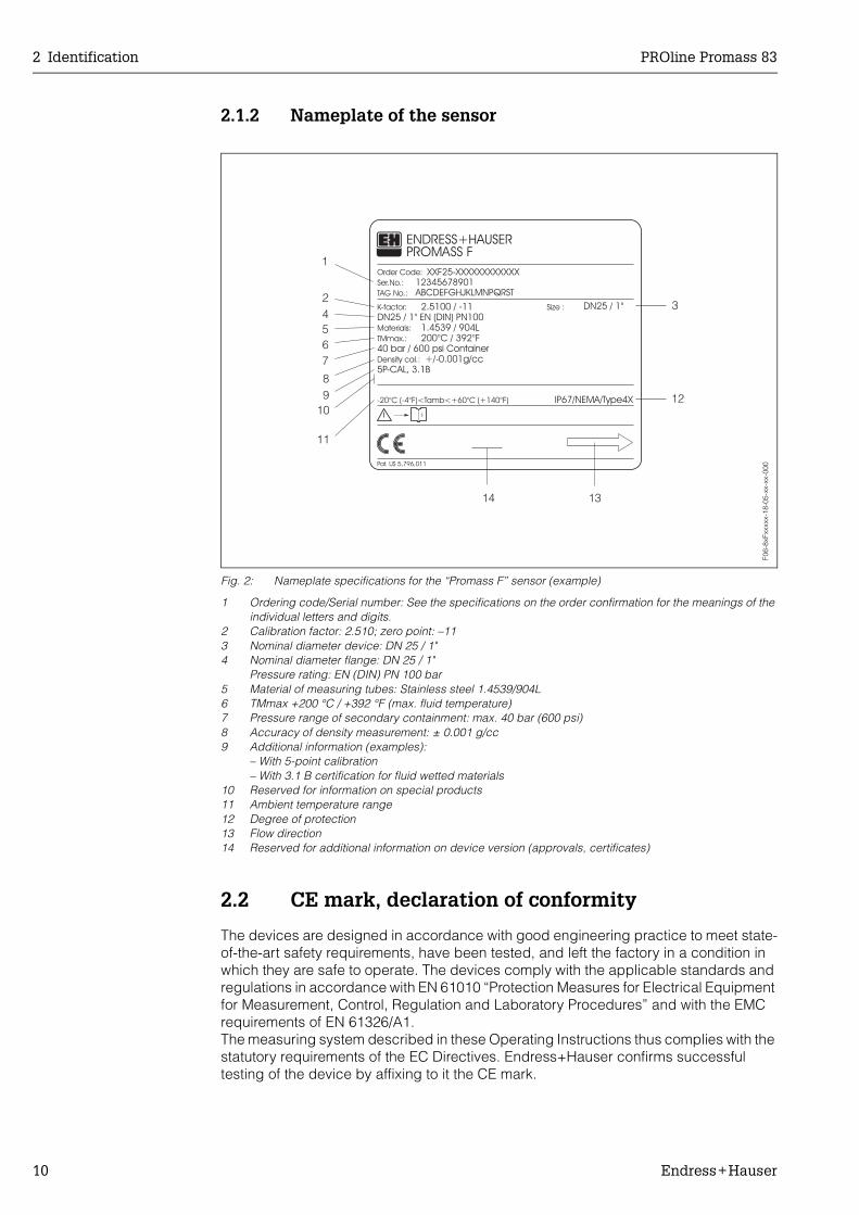
Fig. 2: Nameplate specifications for the “Promass F” sensor (example)
1 Ordering code/Serial number: See the specifications on the order confirmation for the meanings of the individual letters and digits.
2 Calibration factor: 2.510; zero point: –113 Nominal diameter device: DN 25 / 1"4 Nominal diameter flange: DN 25 / 1"
Pressure rating: EN (DIN) PN 100 bar5 Material of measuring tubes: Stainless steel 1.4539/904L6 TMmax +200 °C / +392 °F (max. fluid temperature)7 Pressure range of secondary containment: max. 40 bar (600 psi)8 Accuracy of density measurement: ± 0.001 g/cc9 Additional information (examples):
– With 5-point calibration– With 3.1 B certification for fluid wetted materials
10 Reserved for information on special products11 Ambient temperature range12 Degree of protection13 Flow direction14 Reserved for additional information on device version (approvals, certificates)
2.2 CE mark, declaration of conformity
The devices are designed in accordance with good engineering practice to meet state-of-the-art safety requirements, have been tested, and left the factory in a condition in which they are safe to operate. The devices comply with the applicable standards and regulations in accordance with EN 61010 “Protection Measures for Electrical Equipment for Measurement, Control, Regulation and Laboratory Procedures” and with the EMC requirements of EN 61326/A1.The measuring system described in these Operating Instructions thus complies with the statutory requirements of the EC Directives. Endress+Hauser confirms successful testing of the device by affixing to it the CE mark.
1
24567
89
11
12
13
200°C / 392°F40 bar / 600 psi Container
2.5100 / -11DN25 / 1" EN (DIN) PN100
1.4539 / 904L
5P-CAL, 3.1BDensity cal.:
-20°C (-4°F)<Tamb<+60°C (+140°F)
PROMASS FENDRESS+HAUSER
Pat. US 5,796,011
Materials:
TMmax.:
Order Code:
K-factor:
TAG No.:
Ser.No.:
IP67/NEMA/Type4X
+/-0.001g/cc
XXF25-XXXXXXXXXXXX12345678901ABCDEFGHJKLMNPQRST
i
14
DN25 / 1"Size : 3
10
F06-
8xFx
xxxx
-18-
05-x
x-xx
-000

PROline Promass 83 2 Identification
Endress+Hauser 11
2.3 Registered trademarks
KALREZ ®, VITON ® Registered trademarks of E.I. Du Pont de Nemours & Co., Wilmington, USA
TRI-CLAMP ®
Registered trademark of Ladish & Co., Inc., Kenosha, USA
SWAGELOK ®
Registered trademark of Swagelok & Co., Solon, USA
HART ® Registered trademark of HART Communication Foundation, Austin, USA
S-DAT™, T-DAT™, F-Chip™, FieldTool™, FieldCheck™, Applicator™Registered or registration-pending trademarks of Endress+Hauser Flowtec AG, Reinach, CH

2 Identification PROline Promass 83
12 Endress+Hauser

PROline Promass 83 3 Installation
Endress+Hauser 13
3 Installation
3.1 Incoming acceptance, transport and storage
3.1.1 Incoming acceptance
On receipt of the goods, check the following points:• Check the packaging and the contents for damage.• Check the shipment, make sure nothing is missing and that the scope of supply
matches your order.
3.1.2 Transport
The following instructions apply to unpacking and to transporting the device to its final location:
• Transport the devices in the containers in which they are delivered.• The covers or caps fitted to the process connections prevent mechanical damage to
the sealing faces and the ingress of foreign matter to the measuring tube during trans-portation and storage. Consequently, do not remove these covers or caps until imme-diately before installation.
• Do not lift measuring devices of nominal diameters DN 40...150 by the transmitter housing or the connection housing in the case of the remote version (Fig. 3). Use webbing slings slung round the two process connections. Do not use chains, as they could damage the housing.
• In the case of the Promass M / DN 80 sensor, use only the lifting eyes on the flanges to lift the assembly.
# Warning:Risk of injury if the measuring device slips. The center of gravity of the assembled meas-uring device might be higher than the points around which the slings are slung.At all times, therefore, make sure that the device does not unexpectedly turn around its axis or slip.
Fig. 3: Instructions for transporting sensors with DN 40...150
F06-
xxxx
xxxx
-22-
00-0
0-xx
-000
3 Installation PROline Promass 83
14 Endress+Hauser
3.1.3 Storage
Note the following points:• Pack the measuring device in such a way as to protect it reliably against impact for
storage (and transportation). The original packaging provides optimum protection.• The permissible storage temperature is −40...+80 °C (preferably +20 °C).• Do not remove the protective covers or caps on the process connections until you are
ready to install the device.• The measuring device must be protected against direct sunlight during storage in
order to avoid unacceptably high surface temperatures.
3.2 Installation conditions
Note the following points:• No special measures such as supports are necessary. External forces are absorbed
by the construction of the instrument, for example the secondary containment.• The high oscillation frequency of the measuring tubes ensures that the correct oper-
ation of the measuring system is not influenced by pipe vibrations.• No special precautions need to be taken for fittings which create turbulence (valves,
elbows, T-pieces, etc.), as long as no cavitation occurs.• For mechanical reasons and in order to protect the pipe, it is advisable to support
heavy sensors.
3.2.1 Dimensions
Dimensions and the fitting lengths of the transmitter and sensor are on Page 133 ff.
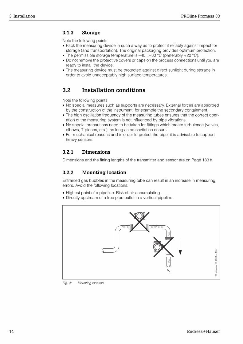
3.2.2 Mounting location
Entrained gas bubbles in the measuring tube can result in an increase in measuring errors. Avoid the following locations:
• Highest point of a pipeline. Risk of air accumulating.• Directly upstream of a free pipe outlet in a vertical pipeline.
Fig. 4: Mounting location
F06-
xxxx
xxxx
-11-
00-0
0-xx
-004
PROline Promass 83 3 Installation
Endress+Hauser 15
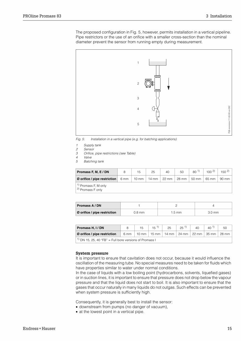
The proposed configuration in Fig. 5, however, permits installation in a vertical pipeline. Pipe restrictors or the use of an orifice with a smaller cross-section than the nominal diameter prevent the sensor from running empty during measurement.
Fig. 5: Installation in a vertical pipe (e.g. for batching applications)
1 Supply tank2 Sensor3 Orifice, pipe restrictions (see Table)4 Valve5 Batching tank
System pressureIt is important to ensure that cavitation does not occur, because it would influence the oscillation of the measuring tube. No special measures need to be taken for fluids which have properties similar to water under normal conditions.In the case of liquids with a low boiling point (hydrocarbons, solvents, liquefied gases) or in suction lines, it is important to ensure that pressure does not drop below the vapour pressure and that the liquid does not start to boil. It is also important to ensure that the gases that occur naturally in many liquids do not outgas. Such effects can be prevented when system pressure is sufficiently high.
Consequently, it is generally best to install the sensor:• downstream from pumps (no danger of vacuum),• at the lowest point in a vertical pipe.
Promass F, M, E / DN 8 15 25 40 50 80 1) 100 2) 150 2)
Ø orifice / pipe restriction 6 mm 10 mm 14 mm 22 mm 28 mm 50 mm 65 mm 90 mm
1) Promass F, M only2) Promass F only
Promass A / DN 1 2 4
Ø orifice / pipe restriction 0.8 mm 1.5 mm 3.0 mm
Promass H, I / DN 8 15 15 1) 25 25 1) 40 40 1) 50
Ø orifice / pipe restriction 6 mm 10 mm 15 mm 14 mm 24 mm 22 mm 35 mm 28 mm1) DN 15, 25, 40 “FB” = Full bore versions of Promass I
F06-
xxxx
xxxx
-11-
00-0
0-xx
-002
3 Installation PROline Promass 83
16 Endress+Hauser
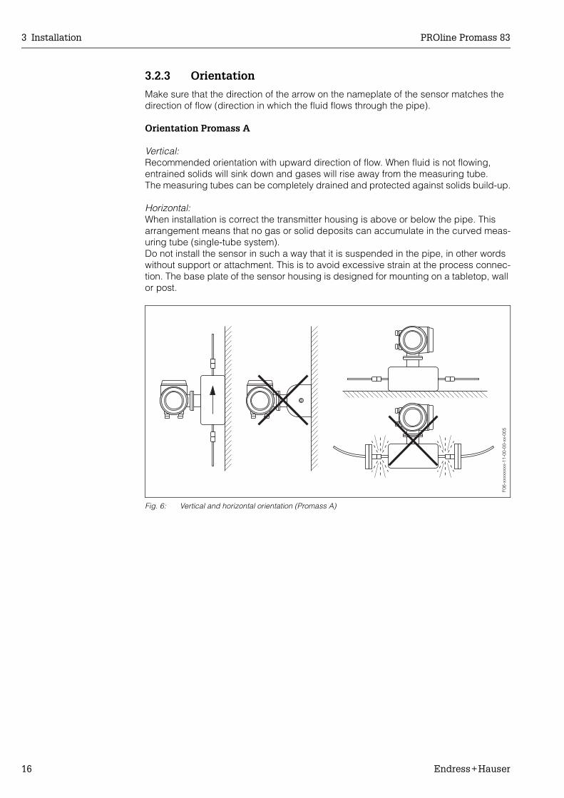
3.2.3 Orientation
Make sure that the direction of the arrow on the nameplate of the sensor matches the direction of flow (direction in which the fluid flows through the pipe).
Orientation Promass A
Vertical:Recommended orientation with upward direction of flow. When fluid is not flowing, entrained solids will sink down and gases will rise away from the measuring tube. The measuring tubes can be completely drained and protected against solids build-up.
Horizontal:When installation is correct the transmitter housing is above or below the pipe. This arrangement means that no gas or solid deposits can accumulate in the curved meas-uring tube (single-tube system).Do not install the sensor in such a way that it is suspended in the pipe, in other words without support or attachment. This is to avoid excessive strain at the process connec-tion. The base plate of the sensor housing is designed for mounting on a tabletop, wall or post.
Fig. 6: Vertical and horizontal orientation (Promass A)F0
6-xx
xxxx
xx-1
1-00
-00-
xx-0
05

PROline Promass 83 3 Installation
Endress+Hauser 17
Orientation Promass F, M, E, H, I
Make sure that the direction of the arrow on the nameplate of the sensor matches the direction of flow (direction in which the fluid flows through the pipe).
Vertical:Recommended orientation with upward direction of flow (View V). When fluid is not flow-ing, entrained solids will sink down and gases will rise away from the measuring tube. The measuring tubes can be completely drained and protected against solids build-up.
Horizontal (Promass F, M, E):The measuring tubes of Promass F, M and E must be horizontal and beside each other. When installation is correct the transmitter housing is above or below the pipe (View H1/H2). Always avoid having the transmitter housing in the same horizontal plane as the pipe.
Horizontal (Promass H, I):Promass H and Promass I can be installed in any orientation in a horizontal pipe run.
= Recommended orientation = Orientation recommended in certain situations = Impermissible orientation
Pro
mas
s F,
M, E
, H, I
Sta
ndar
d, c
omp
act
Pro
mas
s F,
M, E
, H, I
Sta
ndar
d, r
emot
e
Pro
mas
s F
Hig
h-te
mp
erat
ure,
com
pac
t
Pro
mas
s F
Hig
h-te
mp
erat
ure,
rem
ote
Vertical orientation (View V)
Horizontal orientation (View H1)Transmitter head up
(TM = >200 °C)
➀
(TM = >200 °C)
➀
Horizontal orientation (View H2)Transmitter head down
➁
➁
➁
➁
3 Installation PROline Promass 83
18 Endress+Hauser
In order to ensure that the maximum permissible ambient temperature for the transmitter (–20...+60 °C, optional –40...+60 °C) is not exceeded, we recommend the following orientations:
➀ = For fluids with very high temperatures (> 200 °C), we recommend the horizontal orientation with the transmitter head pointing downwards (Fig. H2) or the vertical orien-tation (Fig. V)
➁ = For fluids with low temperatures, we recommend the horizontal orientation with the transmitter head pointing upwards (Fig. H1) or the vertical orientation (Fig. V).
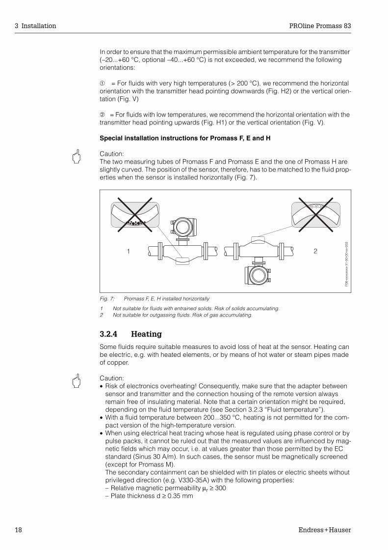
Special installation instructions for Promass F, E and H
" Caution:The two measuring tubes of Promass F and Promass E and the one of Promass H are slightly curved. The position of the sensor, therefore, has to be matched to the fluid prop-erties when the sensor is installed horizontally (Fig. 7).
Fig. 7: Promass F, E, H installed horizontally
1 Not suitable for fluids with entrained solids. Risk of solids accumulating.2 Not suitable for outgassing fluids. Risk of gas accumulating.
3.2.4 Heating
Some fluids require suitable measures to avoid loss of heat at the sensor. Heating can be electric, e.g. with heated elements, or by means of hot water or steam pipes made of copper.
" Caution:• Risk of electronics overheating! Consequently, make sure that the adapter between
sensor and transmitter and the connection housing of the remote version always remain free of insulating material. Note that a certain orientation might be required, depending on the fluid temperature (see Section 3.2.3 “Fluid temperature”).
• With a fluid temperature between 200...350 °C, heating is not permitted for the com-pact version of the high-temperature version.
• When using electrical heat tracing whose heat is regulated using phase control or by pulse packs, it cannot be ruled out that the measured values are influenced by mag-netic fields which may occur, i.e. at values greater than those permitted by the EC standard (Sinus 30 A/m). In such cases, the sensor must be magnetically screened (except for Promass M).The secondary containment can be shielded with tin plates or electric sheets without privileged direction (e.g. V330-35A) with the following properties:– Relative magnetic permeability µr ≥ 300– Plate thickness d ≥ 0.35 mm
F06-
xxxx
xxxx
-11-
00-0
0-xx
-003

PROline Promass 83 3 Installation
Endress+Hauser 19
• Information on permissible temperature ranges → Page 119.
Special heating jackets which can be ordered as accessories from Endress+Hauser are available for the sensors.
3.2.5 Thermal insulation
Some fluids require suitable measures to avoid loss of heat at the sensor. A wide range of materials can be used to provide the required thermal insulation.
Fig. 8: In the case of the Promass F high-temperature version, a maximum insulation thickness of 60 mm must be observed in the area of the electronics/neck.
If the Promass F high-temperature version is installed horizontally (with transmitter head pointing upwards), an insulation thickness of min. 10 mm is recommended to reduce convection. The maximum insulation thickness of 60 mm must be observed (see Fig. 8).
3.2.6 Inlet and outlet runs
There are no installation requirements regarding inlet and outlet runs. If possible, install the sensor well clear of fittings such as valves, T-pieces, elbows, etc.
3.2.7 Vibrations
The high oscillation frequency of the measuring tubes ensures that the correct operation of the measuring system is not influenced by pipe vibrations. Consequently, the sensors require no special measures for attachment.
3.2.8 Limiting flow
See the information on Page 111 and 120.
max. 60
EscEsc
E- +
max. 60
F06-
83FH
Txxx
-06-
00-x
x-xx
-001
3 Installation PROline Promass 83
20 Endress+Hauser
3.3 Installation instructions
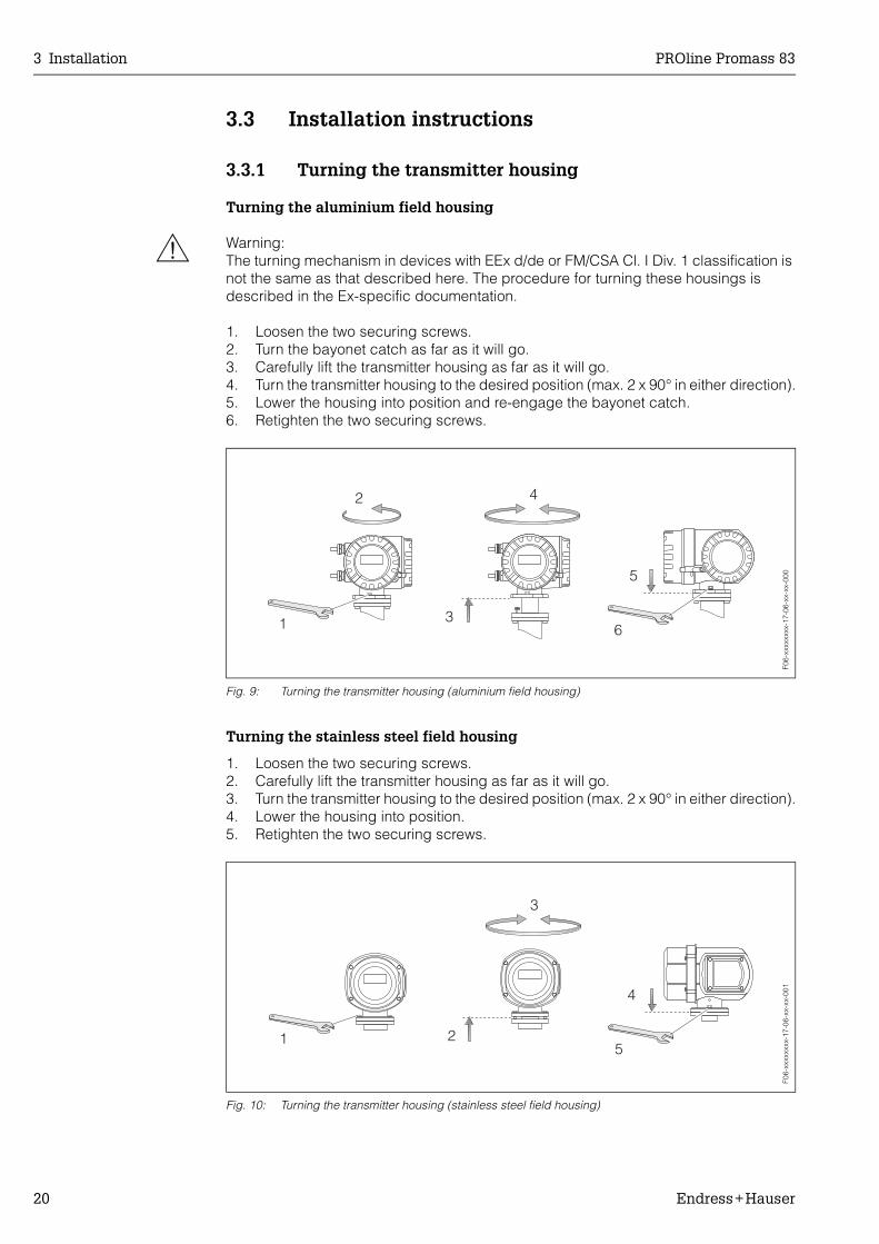
3.3.1 Turning the transmitter housing
Turning the aluminium field housing
# Warning:The turning mechanism in devices with EEx d/de or FM/CSA Cl. I Div. 1 classification is not the same as that described here. The procedure for turning these housings is described in the Ex-specific documentation.
1. Loosen the two securing screws.2. Turn the bayonet catch as far as it will go.3. Carefully lift the transmitter housing as far as it will go.4. Turn the transmitter housing to the desired position (max. 2 x 90° in either direction).5. Lower the housing into position and re-engage the bayonet catch.6. Retighten the two securing screws.
Fig. 9: Turning the transmitter housing (aluminium field housing)
Turning the stainless steel field housing
1. Loosen the two securing screws.2. Carefully lift the transmitter housing as far as it will go.3. Turn the transmitter housing to the desired position (max. 2 x 90° in either direction).4. Lower the housing into position.5. Retighten the two securing screws.
Fig. 10: Turning the transmitter housing (stainless steel field housing)
F06-
xxxx
xxxx
-17-
06-x
x-xx
-000
F06-
xxxx
xxxx
-17-
06-x
x-xx
-001

PROline Promass 83 3 Installation
Endress+Hauser 21
3.3.2 Installing the wall-mount transmitter housing
There are various ways of installing the wall-mount transmitter housing:• Mounted directly on the wall• Installation in control panel (separate mounting set, accessories → Page 87)• Pipe mounting (separate mounting set, accessories → Page 87)
" Caution:• Make sure that ambient temperature does not go beyond the permissible range
(–20...+60 °C). Install the device in a shady location. Avoid direct sunlight.• Always install the wall-mount housing in such a way that the cable entries are pointing
down.
Direct wall mounting
1. Drill the holes as illustrated in Fig. 11.2. Remove the cover of the connection compartment (a).3. Push the two securing screws (b) through the appropriate bores (c) in the housing.
– Securing screws (M6): max. Ø 6.5 mm– Screw head: max. Ø 10.5 mm
4. Secure the transmitter housing to the wall as indicated.5. Screw the cover of the connection compartment (a) firmly onto the housing.
Fig. 11: Mounted directly on the wall
90
35
a
b
19281
.5
c c
F06-
xxxx
xxxx
-17-
03-x
x-xx
-000

3 Installation PROline Promass 83
22 Endress+Hauser
Installation in control panel
1. Prepare the opening in the panel (Fig. 12).2. Slide the housing into the opening in the panel from the front.3. Screw the fasteners onto the wall-mount housing.4. Place the threaded rods in the fasteners and screw them down until the housing is
seated tightly against the panel. Afterwards, tighten the locking nuts. Additional support is not necessary.
Fig. 12: Panel Installation (wall-mount housing)
Pipe mountingThe assembly should be performed by following the instructions in Fig. 13.
" Caution:If the device is mounted to a warm pipe, make certain that the housing temperature does not exceed +60 °C, which is the maximum permissible temperature.
Fig. 13: Pipe mounting (wall-mount housing)
245
~110
+0.
5–
0.5
210+0.5– 0.5
F06-
xxxx
xxxx
-06-
03-0
6-xx
-002
Ø 2
0...7
0
~155
F06-
xxxx
xxxx
-06-
03-0
6-xx
-001

PROline Promass 83 3 Installation
Endress+Hauser 23
3.3.3 Turning the local display
1. Remove the cover of the electronics compartment.2. Press the side latches on the display module and remove it from the electronics
compartment cover plate.3. Rotate the display to the desired position (max. 4 x 45° in each direction), and reset
it into the electronics compartment cover plate.4. Screw the cover of the electronics compartment firmly onto the transmitter housing.
Fig. 14: Turning the local display (field housing)
3.4 Post installation check
Perform the following checks after installing the measuring device in the pipe:
Device condition and specifications Notes
Is the device damaged (visual inspection)? −
Does the device correspond to specifications at the measuring point, including process temperature and pressure, ambient temperature, measuring range, etc.?
see Page 111 ff.
Installation Notes
Does the arrow on the sensor nameplate match the direction of flow through the pipe?
−
Are the measuring point number and labeling correct (visual inspec-tion)?
–
Is the orientation chosen for the sensor correct, in other words suitable for sensor type, fluid properties (outgassing, with entrained solids) and fluid temperature?
see Page 14 ff.
Process environment / process conditions Notes
Is the measuring device protected against moisture and direct sunlight?
−
F06-
xxxx
xxxx
-07-
xx-0
6-xx
-000

3 Installation PROline Promass 83
24 Endress+Hauser

PROline Promass 83 4 Wiring
Endress+Hauser 25
4 Wiring
# Warning:When connecting Ex-certified devices, see the notes and diagrams in the Ex-specific supplement to these Operating Instructions. Please do not hesitate to contact your E+H representative if you have any questions.
4.1 Connecting the remote version
4.1.1 Connecting the sensor
# Warning:• Risk of electric shock. Switch off the power supply before opening the device. Do not
install or wire the device while it is connected to the power supply. Failure to comply with this precaution can result in irreparable damage to the electronics.
• Risk of electric shock. Connect the protective conductor to the ground terminal on the housing before the power supply is applied.
• For the remote version, always make sure that you connect the sensor only to the transmitter having the same serial number. Communication errors can occur if the devices are not connected in this way.
1. Remove the cover (a) of the connection compartment from the transmitter and the sensor by loosening the screws.
2. Feed the signal cable (b) through the appropriate cable entries.3. Establish the connections between sensor and transmitter in accordance with the
wiring diagram:→ Fig. 15→ wiring diagram inside cover
4. Secure the cover (a) on the sensor connection housing and on the transmitter housing.
Fig. 15: Connecting the remote version
a Covers of the connection compartments (transmitter, sensor)b Connecting cable (signal cable)
6
6
4
4
7
7
5
5
8
8
9
9
10
10
11
11
12
12
41
41
42
42
S1+ + + +
S1 S2 S2 TM TM TT TTGNDPipe
S1+ + + +
S1 S2 S2 TM TM TT TTGNDPipe
a
ba
brn
brn
wht
wht
grn
grn
gry
gry
yel
yel
pnk
pnk
F06-
8xxx
xxxx
-04-
xx-x
x-en
-000

4 Wiring PROline Promass 83
26 Endress+Hauser
4.1.2 Cable specifications
The specifications of the cable connecting the transmitter and the sensor of the remote version are as follows:
• 6 x 0.38 mm2 PVC cable with common shield and individually shielded cores.• Conductor resistance: ≤ 50 Ω/km• Capacitance: core/shield: ≤ 420 pF/m• Cable length: max. 20 m• Permanent operating temperature: max. +105 °C

PROline Promass 83 4 Wiring
Endress+Hauser 27
4.2 Connecting the measuring unit
4.2.1 Transmitter (aluminium)
# Warning:• Risk of electric shock. Switch off the power supply before opening the device. Do not
install or wire the device while it is connected to the power supply. Failure to comply with this precaution can result in irreparable damage to the electronics.
• Risk of electric shock. Connect the protective conductor to the ground terminal on the housing before the power supply is applied.
• Compare the specifications on the nameplate with the local voltage supply and fre-quency. The national regulations governing the installation of electrical equipment also apply.
1. Remove the cover of the connection compartment (f) from the transmitter housing.2. Feed the power supply cable (a) and signal cables (b) through the appropriate
cable entries.3. Connect the cables in accordance with the wiring diagram:
– Wiring diagram (aluminium housing) → Fig. 16– Wiring diagram (stainless steel housing) → Fig. 17– Wiring diagram (wall-mount housing) → Fig. 18– Terminal assignment → Page 29
4. Screw the cover of the connection compartment (f) firmly onto the transmitter housing.
Fig. 16: Connecting the transmitter (aluminium field housing). Cable cross-section: max. 2.5 mm2
a Cable for power supply: 85...260 V AC, 20...55 V AC, 16...62 V DC Terminal No. 1: L1 for AC, L+ for DCTerminal No. 2: N for AC, L− for DC
b Signal cable: Terminals Nos. 20–27 → Page 29c Ground terminal for protective conductord Ground terminal for signal cable shielde Service adapter for connecting service interface FXA 193 (FieldCheck, FieldTool)f Cover of the connection compartmentg Securing clamp
bb
c
d
a
a
– 27
– 25
– 23
– 21
21
+ 26
+ 24
+ 22
+ 20
L1 (L+)N (L-)
g
f
e
F06-
xxxx
xxxx
-04-
06-x
x-xx
-005

4 Wiring PROline Promass 83
28 Endress+Hauser
Fig. 17: Connecting the transmitter (stainless-steel field housing). Cable cross-section: max. 2.5 mm2
a Cable for power supply: 85...260 V AC, 20...55 V AC, 16...62 V DC Terminal No. 1: L1 for AC, L+ for DCTerminal No. 2: N for AC, L− for DC
b Signal cable: Terminals Nos. 20–27 → Page 29c Ground terminal for protective conductord Ground terminal for signal cable shielde Service adapter for connecting service interface FXA 193 (FieldCheck, FieldTool)f Cover of the connection compartment
Fig. 18: Connecting the transmitter (wall-mount housing). Cable cross-section: max. 2.5 mm2
a Cable for power supply: 85...260 V AC, 20...55 V AC, 16...62 V DC Terminal No. 1: L1 for AC, L+ for DCTerminal No. 2: N for AC, L− for DC
b Signal cable: Terminals Nos. 20–27 → Page 29c Ground terminal for protective conductord Ground terminal for signal cable shielde Service adapter for connecting service interface FXA 193 (FieldCheck, FieldTool)f Cover of the connection compartment
b
c
d
a
21L1 (L+)
N (L-)f
b
a
e
– 27
– 25
– 23
– 21
+ 26
+ 24
+ 22
+ 20
F06-
xxxx
xxxx
-04-
06-x
x-xx
-006
1 2
c d
e
aa bb
f
+22
–23
+20
–21
+24
–25
+26
–27
L1 (L+)N (L-)
F06-
xxxx
xxxx
-04-
03-x
x-xx
-000

PROline Promass 83 4 Wiring
Endress+Hauser 29
4.2.2 Terminal assignment
Terminal Nos. (inputs/outputs)
Order variant 20 (+) / 21 (–) 22 (+) / 23 (–) 24 (+) / 25 (–) 26 (+) / 27 (–)
Fixed communication boards (permanent assignment)
83***-***********A − − Frequency outputCurrent output
HART
83***-***********B Relay output Relay output Frequency outputCurrent output
HART
83***-***********F – – – PROFIBUS-PA Ex i
83***-***********G – – –FOUNDATION Field-
bus, Ex i
83***-***********H – – –PROFIBUS-PA
83***-***********J – – –PROFIBUS-DP
83***-***********K – – –FOUNDATION
Fieldbus
83***-***********R – –Current output 2
Ex i, activeCurrent output 1 Ex i active, HART
83***-***********S – –Frequency output
Ex i, passiveCurrent output Ex i
active, HART
83***-***********T – –Frequency output
Ex i, passiveCurrent output Ex i
passive, HART
83***-***********U – –Current output 2
Ex i, passiveCurrent output 1
Ex i passive, HART
Flexible communication boards
83***-***********C Relay output 2 Relay output 1 Frequency outputCurrent output
HART
83***-***********D Status input Relay output Frequency outputCurrent output
HART
83***-***********E Status input Relay output Current output 2Current output 1
HART
83***-***********L Status input Relay output 2 Relay output 1Current output
HART
83***-***********M Status input Frequency output 2 Frequency output 1Current output
HART
83***-***********W Relay output Current output 3 Current output 2Current output 1
HART
83***-***********0 Status input Current output 3 Current output 2Current output 1
HART
83***-***********2 Relay output Current output 2 Frequency outputCurrent output 1
HART
83***-***********3 Current input Relay output Current output 2Current output 1
HART
83***-***********4 Current input Relay output Frequency outputCurrent output
HART
83***-***********5 Status input Current input Frequency outputCurrent output
HART
83***-***********6 Status input Current input Current output 2Current output
HART
4 Wiring PROline Promass 83
30 Endress+Hauser
Electrical values for inputs/outputs
Status input (auxiliary input):galvanically isolated, 3...30 V DC, Ri = 5 kΩ, configurable
Current input:active/passive selectable, galvanically isolated, resolution: 2 µA• active: 4...20 mA, Ri ≤ 150 Ω, Uout = 24 V DC, short-circuit proof• passive: 0/4...20 mA, Ri ≤ 150 Ω, Umax = 30 V DC
Relay output:• max. 60 V DC / 0.1 A, max. 30 V AC / 0.5 A; configurable
Frequency output:active/passive selectable, galvanically isolated• active: 24 V DC, 25 mA (max. 250 mA during 20 ms), RL > 100 Ω• passive: open collector, 30 V DC, 250 mA
• Frequency output: full scale frequ. 2...10000 Hz (fmax = 12500 Hz), on/off ratio 1:1, pulse width max. 2 s
• pulse output: pulse value and pulse polarity selectable, pulse width configurable (0.05…2000 ms)
Current output (active/passive):galvanically isolated, • active: 0/4...20 mA, RL < 700 Ω (HART: RL ≥ 250 Ω),• passive: 4...20 mA; supply voltage VS 18...30 V DC; RL ≤ 700 Ω
PROline Promass 83 4 Wiring
Endress+Hauser 31
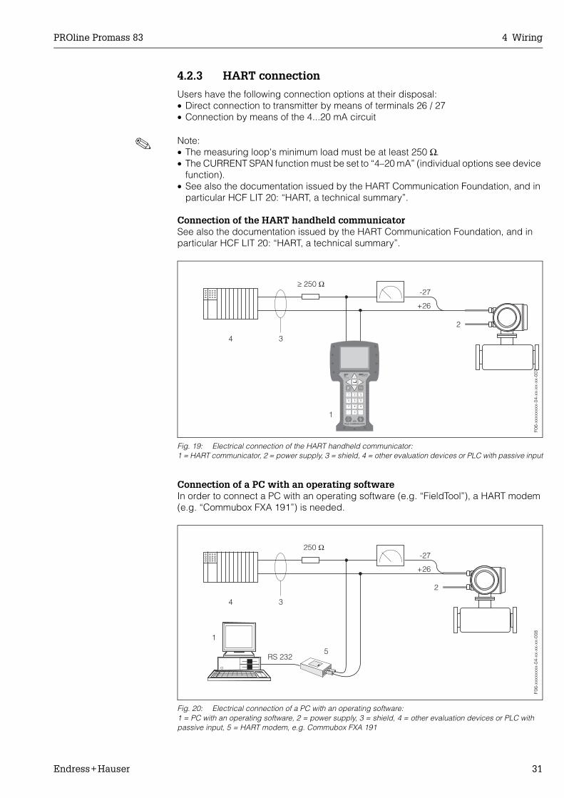
4.2.3 HART connection
Users have the following connection options at their disposal:• Direct connection to transmitter by means of terminals 26 / 27• Connection by means of the 4...20 mA circuit
! Note:• The measuring loop's minimum load must be at least 250 Ω.• The CURRENT SPAN function must be set to “4–20 mA” (individual options see device
function).• See also the documentation issued by the HART Communication Foundation, and in
particular HCF LIT 20: “HART, a technical summary”.
Connection of the HART handheld communicatorSee also the documentation issued by the HART Communication Foundation, and in particular HCF LIT 20: “HART, a technical summary”.
Fig. 19: Electrical connection of the HART handheld communicator:1 = HART communicator, 2 = power supply, 3 = shield, 4 = other evaluation devices or PLC with passive input
Connection of a PC with an operating softwareIn order to connect a PC with an operating software (e.g. “FieldTool”), a HART modem (e.g. “Commubox FXA 191”) is needed.
Fig. 20: Electrical connection of a PC with an operating software:1 = PC with an operating software, 2 = power supply, 3 = shield, 4 = other evaluation devices or PLC with passive input, 5 = HART modem, e.g. Commubox FXA 191
+26
≥ Ω250-27
1
34
2
1# % &
Copy
G H I
P Q R S
, ( ) ‘
A B C
Paste
PageOn
PageUp
DeleteBksp
Insert
J K L
T U V
_ < >
D E F
Hot Key
+ Hot Key
M N O
W X Y Z
+ * /
4
7
.
2
5
8
0
375FIELD COMMUNICATOR
3
6
9
-
9 6
F06-
xxxx
xxxx
-04-
xx-x
x-xx
-007
F06-
xxxx
xxxx
-04-
xx-x
x-xx
-008

4 Wiring PROline Promass 83
32 Endress+Hauser
4.3 Degree of protection
The devices fulfill all the requirements for IP 67. Compliance with the following points is mandatory following installation in the field or servicing, in order to ensure that IP 67 pro-tection is maintained:
• The housing seals must be clean and undamaged when inserted into their grooves. The seals must be dried, cleaned or replaced if necessary.
• All threaded fasteners and screw covers must be firmly tightened.• The cables used for connection must be of the specified outside diameter
(see Page 114).• Firmly tighten the cable entries (Fig. 21). • The cables must loop down before they enter the cable entries (“water trap”, Fig. 21).
This arrangement prevents moisture penetrating the entry. Always install the measur-ing device in such a way that the cable entries do not point up.
• Remove all unused cable entries and insert plugs instead.• Do not remove the grommet from the cable entry.
Fig. 21: Installation instructions, cable entries
F06-
5xxx
xxxx
-04-
xx-x
x-xx
-005

PROline Promass 83 4 Wiring
Endress+Hauser 33
4.4 Post connection check
Perform the following checks after completing electrical installation of the measuring device:
Device condition and specifications Notes
Are cables or the device damaged (visual inspection)? −
Electrical connection Notes
Does the supply voltage match the specifications on the nameplate? 85...260 V AC (45...65 Hz)20...55 V AC (45...65 Hz)16...62 V DC
Do the cables comply with the specifications? see Page 26, 114
Do the cables have adequate strain relief? −
Cables correctly segregated by type?Without loops and crossovers?
−
Are the power supply and signal cables correctly connected? See the wiring diagram inside the cover of the terminal compartment
Are all screw terminals firmly tightened? −
Are all cable entries installed, firmly tightened and correctly sealed?Cables looped as “water traps”?
see Page 32
Are all housing covers installed and firmly tightened? −

4 Wiring PROline Promass 83
34 Endress+Hauser
PROline Promass 83 5 Operation
Endress+Hauser 35
5 Operation
5.1 Display and operating elements
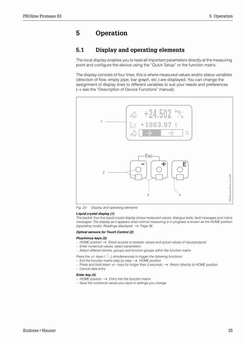
The local display enables you to read all important parameters directly at the measuring point and configure the device using the “Quick Setup” or the function matrix.
The display consists of four lines; this is where measured values and/or status variables (direction of flow, empty pipe, bar graph, etc.) are displayed. You can change the assignment of display lines to different variables to suit your needs and preferences (→ see the “Description of Device Functions” manual).
Fig. 22: Display and operating elements
Liquid crystal display (1)The backlit, four-line liquid crystal display shows measured values, dialogue texts, fault messages and notice messages. The display as it appears when normal measuring is in progress is known as the HOME position (operating mode). Readings displayed → Page 36
Optical sensors for Touch Control (2)
Plus/minus keys (3)– HOME position → Direct access to totalizer values and actual values of inputs/outputs– Enter numerical values, select parameters– Select different blocks, groups and function groups within the function matrix
Press the +/– keys ( X) simultaneously to trigger the following functions:– Exit the function matrix step by step → HOME position– Press and hold down +/− keys for longer than 3 seconds → Return directly to HOME position– Cancel data entry
Enter key (4)– HOME position → Entry into the function matrix– Save the numerical values you input or settings you change
Esc
E+-
1
2
3 4
+24.502+1863.97
kg
th
–50 +50 %
m
3Σm
+24.502+1863.97
kg
th
–50 +50 %
m
3Σm
F06-
83xx
xxxx
-07-
xx-x
x-xx
-000
5 Operation PROline Promass 83
36 Endress+Hauser
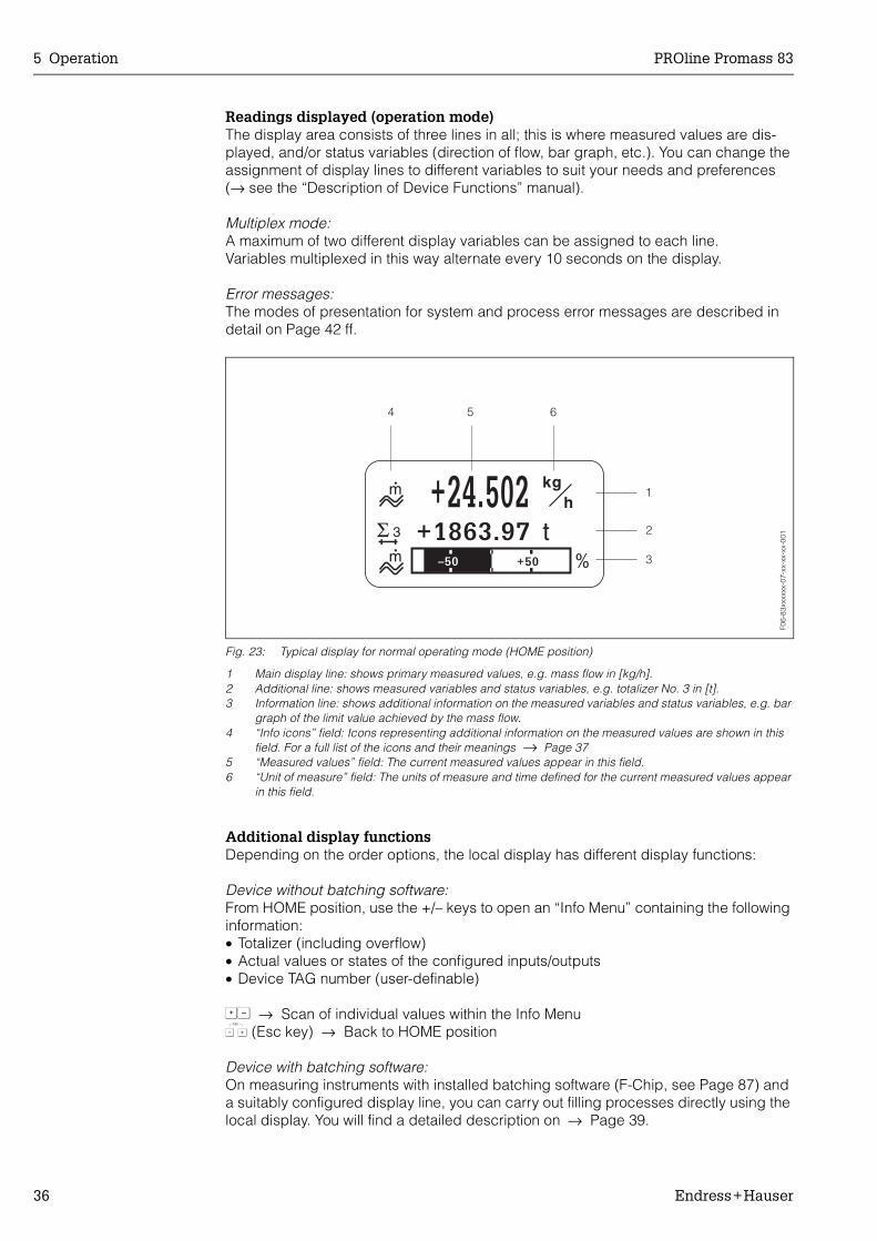
Readings displayed (operation mode)The display area consists of three lines in all; this is where measured values are dis-played, and/or status variables (direction of flow, bar graph, etc.). You can change the assignment of display lines to different variables to suit your needs and preferences (→ see the “Description of Device Functions” manual).
Multiplex mode:A maximum of two different display variables can be assigned to each line.Variables multiplexed in this way alternate every 10 seconds on the display.
Error messages:The modes of presentation for system and process error messages are described in detail on Page 42 ff.
Fig. 23: Typical display for normal operating mode (HOME position)
1 Main display line: shows primary measured values, e.g. mass flow in [kg/h].2 Additional line: shows measured variables and status variables, e.g. totalizer No. 3 in [t].3 Information line: shows additional information on the measured variables and status variables, e.g. bar
graph of the limit value achieved by the mass flow.4 “Info icons” field: Icons representing additional information on the measured values are shown in this
field. For a full list of the icons and their meanings → Page 375 “Measured values” field: The current measured values appear in this field.6 “Unit of measure” field: The units of measure and time defined for the current measured values appear
in this field.
Additional display functionsDepending on the order options, the local display has different display functions:
Device without batching software:From HOME position, use the +/– keys to open an “Info Menu” containing the following information:• Totalizer (including overflow)• Actual values or states of the configured inputs/outputs• Device TAG number (user-definable)
OS → Scan of individual values within the Info MenuX (Esc key) → Back to HOME position
Device with batching software:On measuring instruments with installed batching software (F-Chip, see Page 87) and a suitably configured display line, you can carry out filling processes directly using the local display. You will find a detailed description on → Page 39.
+24.502+1863.97
kg
th
–50 +50 %
m
3Σ
1
4 5 6
2
3m
F06-
83xx
xxxx
-07-
xx-x
x-xx
-001

PROline Promass 83 5 Operation
Endress+Hauser 37
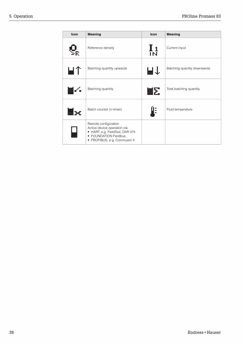
IconsThe icons which appear in the field on the left make it easier to read and recognise measured variables, device status, and error messages.
Icon Meaning Icon Meaning
S System error P Process error
$ Fault message(with effect on outputs)
! Notice message(without effect on outputs)
| 1...nCurrent output 1...n orCurrent input
P 1...n Pulse output 1...n
F 1...n Frequency output 1...n S 1...nStatus/relay output 1...n (or status input)
Σ 1...n Summenzähler 1...n
Measuring mode;PULSATING FLOW
Measuring mode;SYMMETRY (bidirectional)
Measuring mode;STANDARD
Counting mode, totalizer;BALANCE (forward and reverse flow)
Counting mode, totalizer;forward
Counting mode, totalizer;reverse
Status input Volume flow
Target volume flow Target corrected volume flow
Carrier volume flow Carrier corrected volume flow
% Target volume flow % Target corrected volume flow
Mass flow Target mass flow
% Target mass flow Carrier mass flow
% Carrier mass flow Fluid density
y
y
y
5 Operation PROline Promass 83
38 Endress+Hauser
Reference density Current input
Batching quantity upwards Batching quantity downwards
Batching quantity Total batching quantity
Batch counter (x times) Fluid temperature
Remote configurationActive device operation via:• HART, e.g. FieldTool, DXR 375• FOUNDATION Fieldbus• PROFIBUS, e.g. Commuwin II
Icon Meaning Icon Meaning
PROline Promass 83 5 Operation
Endress+Hauser 39
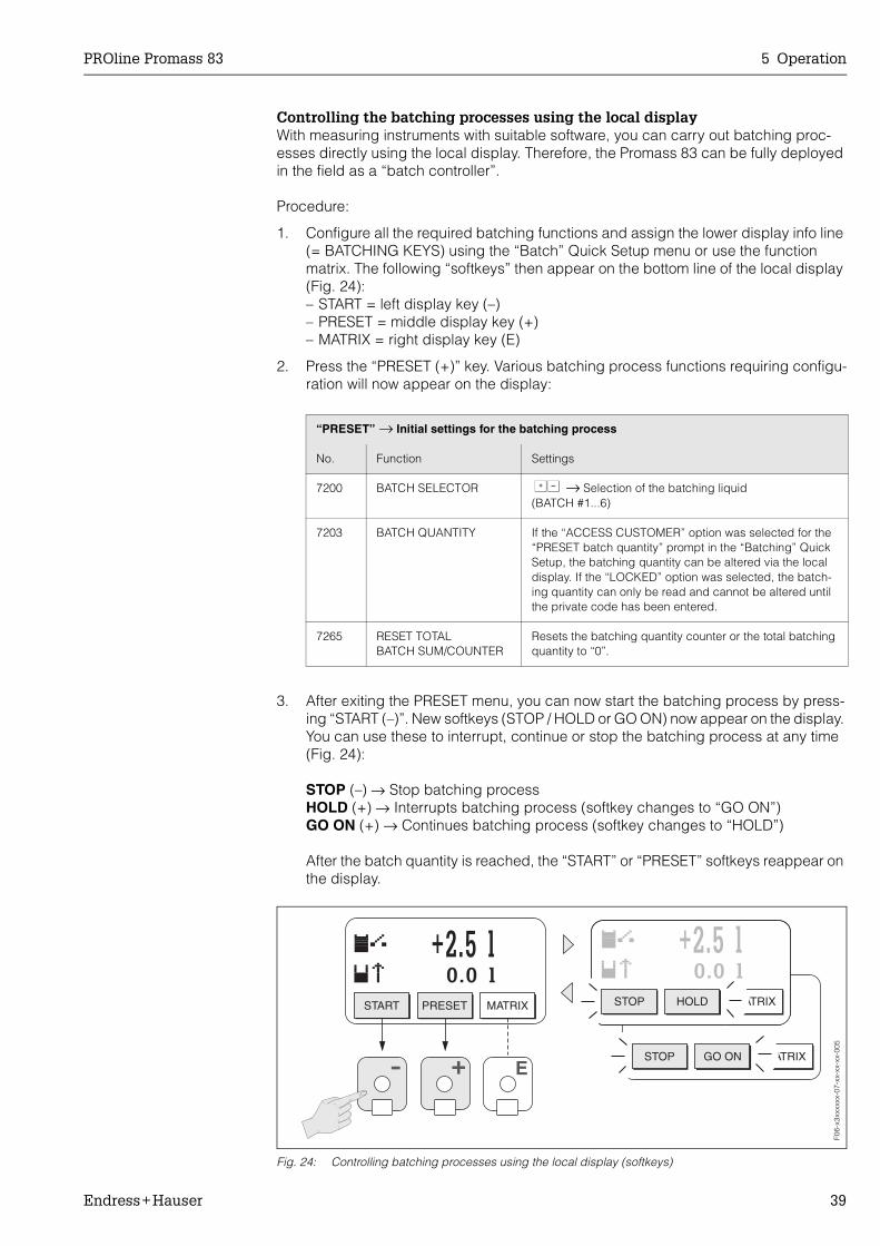
Controlling the batching processes using the local displayWith measuring instruments with suitable software, you can carry out batching proc-esses directly using the local display. Therefore, the Promass 83 can be fully deployed in the field as a “batch controller”.
Procedure:
1. Configure all the required batching functions and assign the lower display info line (= BATCHING KEYS) using the “Batch” Quick Setup menu or use the function matrix. The following “softkeys” then appear on the bottom line of the local display (Fig. 24):– START = left display key (–)– PRESET = middle display key (+)– MATRIX = right display key (E)
2. Press the “PRESET (+)” key. Various batching process functions requiring configu-ration will now appear on the display:
3. After exiting the PRESET menu, you can now start the batching process by press-ing “START (–)”. New softkeys (STOP / HOLD or GO ON) now appear on the display. You can use these to interrupt, continue or stop the batching process at any time (Fig. 24):
STOP (–) → Stop batching processHOLD (+) → Interrupts batching process (softkey changes to “GO ON”)GO ON (+) → Continues batching process (softkey changes to “HOLD”)
After the batch quantity is reached, the “START” or “PRESET” softkeys reappear on the display.
Fig. 24: Controlling batching processes using the local display (softkeys)
“PRESET” → Initial settings for the batching process
No. Function Settings
7200 BATCH SELECTOR OS → Selection of the batching liquid(BATCH #1...6)
7203 BATCH QUANTITY If the “ACCESS CUSTOMER” option was selected for the “PRESET batch quantity” prompt in the “Batching” Quick Setup, the batching quantity can be altered via the local display. If the “LOCKED” option was selected, the batch-ing quantity can only be read and cannot be altered until the private code has been entered.
7265 RESET TOTALBATCH SUM/COUNTER
Resets the batching quantity counter or the total batching quantity to “0”.
STOP GO ON MATRIX
+2.5 l0.0 l
E
+2.5 l0.0 l0.0 l
+-
+2.5 l0.0 l
START PRESET MATRIX STOP HOLD MATRIX
F06-
x3xx
xxxx
-07-
xx-x
x-xx
-005

5 Operation PROline Promass 83
40 Endress+Hauser
5.2 Brief operating instructions to the function matrix
! Note:• See the general notes on Page 41.• Function descriptions → see the “Description of Device Functions” manual
1. HOME position → F → Enter the function matrix2. Select a block (e.g. OUTPUTS)3. Select a group (e.g. CURRENT OUTPUT 1)4. Select a function group (e.g. SETTINGS)5. Select a function (e.g. TIME CONSTANT)
Change parameter / enter numerical values:OS → select or enter: enable code, parameters, numerical valuesF → save your entries
6. Exit the function matrix:– Press and hold down Esc key (X) for longer than 3 seconds → HOME position– Repeatedly press Esc key (X) → return step by step to HOME position
Fig. 25: Selecting functions and configuring parameters (function matrix)
F06-
x3xx
xxxx
-19-
xx-x
x-xx
-000
PROline Promass 83 5 Operation
Endress+Hauser 41
General notesThe Quick Setup menu (see Page 60) contains the default settings that are adequate for commissioning.Complex measuring operations on the other hand necessitate additional functions that you can configure as necessary and customise to suit your process parameters. The function matrix, therefore, comprises a multiplicity of additional functions which, for the sake of clarity, are arranged on a number of menu levels (blocks, groups, and function groups).
Comply with the following instructions when configuring functions:• You select functions as described on Page 40. Each cell in the function matrix is iden-
tified by a numerical or letter code on the display.• You can switch off certain functions (OFF). If you do so, related functions in other
function groups will no longer be displayed.• Certain functions prompt you to confirm your data entries. Press OS to select “SURE
[ YES ]” and press F again to confirm. This saves your setting or starts a function, as applicable.
• Return to the HOME position is automatic if no key is pressed for 5 minutes.
! Note:• The transmitter continues to measure while data entry is in progress, i.e. the currently
measured values are output via the signal outputs in the normal way.• If the power supply fails all preset and parameterised values remain safely stored in
the EEPROM.
" Caution:All functions are described in detail, as is the function matrix itself, in the “Description of Device Functions” manual, which is a separate part of these Operating Instructions.
Enabling the programming modeThe function matrix can be disabled. Disabling the function matrix rules out the possi-bility of inadvertent changes to device functions, numerical values or factory settings. A numerical code (factory setting = 83) has to be entered before settings can be changed.If you use a code number of your choice, you exclude the possibility of unauthorised persons accessing data (→ see the “Description of Device Functions” manual).
Comply with the following instructions when entering codes:• If programming is disabled and the OS keys are pressed in any function, a prompt
for the code automatically appears on the display.• If “0” is entered as the customer's code, programming is always enabled.• The E+H service organisation can be of assistance if you mislay your personal code.
" Caution:Changing certain parameters such as all sensor characteristics, for example, influences numerous functions of the entire measuring system, particularly measuring accuracy. There is no need to change these parameters under normal circumstances and conse-quently, they are protected by a special code known only to the E+H service organisa-tion. Please contact Endress+Hauser if you have any questions.

5 Operation PROline Promass 83
42 Endress+Hauser
Disabling the programming modeProgramming mode is disabled if you do not press a key within 60 seconds following automatic return to the HOME position.You can also disable programming in the “ACCESS CODE” function by entering any number (other than the customer's code).
5.3 Error messages
Type of errorErrors that occur during commissioning or measuring are displayed immediately. If two or more system or process errors occur, the error with the highest priority is the one shown on the display.
The measuring system distinguishes between two types of error:• System error: This group includes all device errors, e.g. communication errors,
hardware errors, etc. → Page 90• Process error: This group includes all application errors, e.g. fluid not homogeneous,
etc. → Page 98
Fig. 26: Error messages on the display (example)
1 Error type: P = process error, S = system error2 Error message type: $ = fault message, ! = notice message3 Error designation: e.g. FLUID INHOM. = fluid is not homogeneous4 Error number: e.g. # 7025 Duration of most recent error occurrence (in hours, minutes and seconds)
Error message typeUsers have the option of weighting system and process errors differently, by defining them as “Fault messages” or “Notice messages”. You can define messages in this way with the aid of the function matrix (see the “Description of Device Functions” man-ual).Serious system errors, e.g. module defects, are always identified and classed as “fault messages” by the measuring device.
Notice message (!)• Displayed as → Exclamation mark (!), error designation (S: system error, P: process
error).• The error in question has no effect on the outputs of the measuring device.
Fault message ( $)• Displayed as → Lightning flash ( $), error designation (S: system error,
P: process error).• The error in question has a direct effect on the outputs.
The response of the outputs (failsafe mode) can be defined by means of functions in the function matrix (see Page 101).
F06-
83xx
xxxx
-07-
xx-x
x-xx
-002

PROline Promass 83 5 Operation
Endress+Hauser 43
! Note:• Error conditions can be output via the relay outputs• If an error message occurs, an upper or lower signal level for the breakdown informa-
tion according to NAMUR 43 can be output via the current output.
Confirming error messagesFor the sake of plant and process safety, the measuring device can be configured in such a way that fault messages ($) always have to be rectified and acknowledged locally by pressing F . Only then do the error messages disappear from the display.This option can be switched on or off by means of the “ACKNOWLEDGE FAULT MESSAGES” function (see the “Description of Device Functions” manual).
! Note:• Fault messages ($) can also be reset and confirmed via the status input.• Notice messages (!) do not require acknowledgment. Note, however, that they remain
visible until the cause of the error has been rectified.
5.4 Communication (HART)
In addition to local operation, the measuring device can be configured and measured values can be obtained by means of the HART protocol. Digital communication takes place using the 4–20 mA current output HART (see Page 31).
The HART protocol allows the transfer of measuring and device data between the HART master and the field devices for configuration and diagnostics purposes. The HART master, e.g. a handheld terminal or PC-based operating programs (such as FieldTool), require device description (DD) files which are used to access all the information in a HART device. Information is exclusively transferred using so-called “commands”. There are three dif-ferent command groupes:
Universal commands:All HART device support and use universal commands. The following functionalities are linked to them:• Recognizing HART devices• Reading digital measured values (volume flow, totalizer, etc.)
Common practice commands:Common practice commands offer functions which are supported and can be executed by most but not all field devices.
Device-specific commands:These commands allow access to device-specific functions which are not HART stand-ard. Such commands access individual field device information, amongst other things, such as empty/full pipe calibration values, creepage settings, etc.
! Note!Promass 83 has access to all three command classes. On Page 46, you will find a list with all the supported “Universal Commands” and “Common Practice Commands”.
5 Operation PROline Promass 83
44 Endress+Hauser
5.4.1 Operating options
For the complete operation of the measuring device, including device-specific com-mands, there are DD files available to the user to provide the following operating aids and programs:
HART Communicator DXR 375Selecting device functions with a HART Communicator is a process involving a number of menu levels and a special HART function matrix. The HART manual in the carrying case of the HART Communicator contains more detailed information on the device.
FieldTool operating programFieldTool is a universal service and configuration software package designed for the PROline measuring devices. Connection is by means of a HART-Modem, e.g. Com-mubox FXA 191.
The functionality of FieldTool includes the following:• Configuration of device functions• Visualization of measuring values (including data logging)• Data backup of device parameters• Advanced device diagnosis• Measuring-point documentation
You can find more information on FieldTool in the following E+H document:System Information: SI 031D/06/en “FieldTool”
Other operating programs• Operating program “AMS” (Fisher Rosemount)• Operating program “SIMATIC PDM” (Siemens)
! Note:• The HART protocol requires the “4…20 mA setting (individual options see device
function) in the CURRENT SPAN function (current output 1).• HART write protection can be disabled or enabled by means of a jumper on the
I/O board → Page 57.
PROline Promass 83 5 Operation
Endress+Hauser 45
5.4.2 Device and process variables
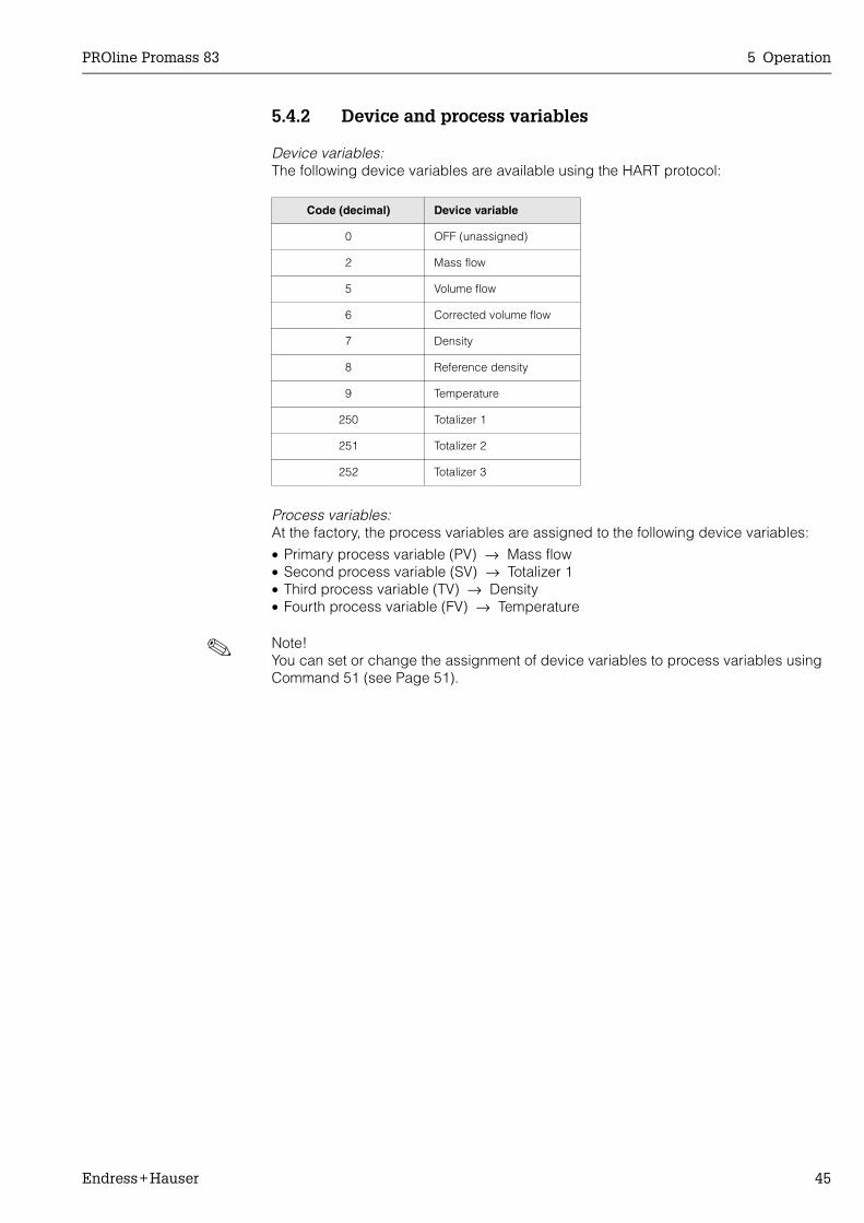
Device variables:The following device variables are available using the HART protocol:
Process variables:At the factory, the process variables are assigned to the following device variables:
• Primary process variable (PV) → Mass flow• Second process variable (SV) → Totalizer 1• Third process variable (TV) → Density• Fourth process variable (FV) → Temperature
! Note!You can set or change the assignment of device variables to process variables using Command 51 (see Page 51).
Code (decimal) Device variable
0 OFF (unassigned)
2 Mass flow
5 Volume flow
6 Corrected volume flow
7 Density
8 Reference density
9 Temperature
250 Totalizer 1
251 Totalizer 2
252 Totalizer 3
5 Operation PROline Promass 83
46 Endress+Hauser
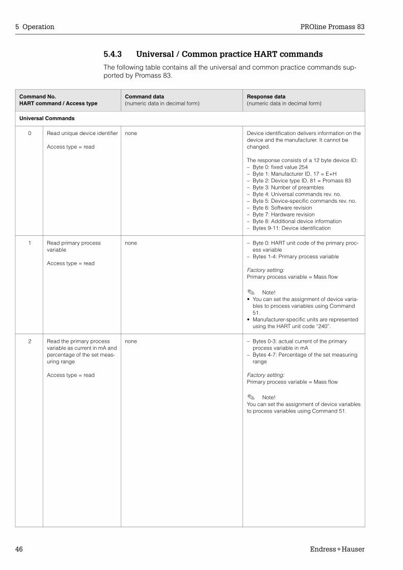
5.4.3 Universal / Common practice HART commands
The following table contains all the universal and common practice commands sup-ported by Promass 83.
Command No.HART command / Access type
Command data(numeric data in decimal form)
Response data(numeric data in decimal form)
Universal Commands
0 Read unique device identifier
Access type = read
none Device identification delivers information on the device and the manufacturer. It cannot be changed.
The response consists of a 12 byte device ID:– Byte 0: fixed value 254– Byte 1: Manufacturer ID, 17 = E+H– Byte 2: Device type ID, 81 = Promass 83– Byte 3: Number of preambles– Byte 4: Universal commands rev. no.– Byte 5: Device-specific commands rev. no.– Byte 6: Software revision– Byte 7: Hardware revision– Byte 8: Additional device information– Bytes 9-11: Device identification
1 Read primary process variable
Access type = read
none – Byte 0: HART unit code of the primary proc-ess variable
– Bytes 1-4: Primary process variable
Factory setting:Primary process variable = Mass flow
! Note!• You can set the assignment of device varia-
bles to process variables using Command 51.
• Manufacturer-specific units are represented using the HART unit code “240”.
2 Read the primary process variable as current in mA and percentage of the set meas-uring range
Access type = read
none – Bytes 0-3: actual current of the primary process variable in mA
– Bytes 4-7: Percentage of the set measuring range
Factory setting:Primary process variable = Mass flow
! Note!You can set the assignment of device variables to process variables using Command 51.
PROline Promass 83 5 Operation
Endress+Hauser 47
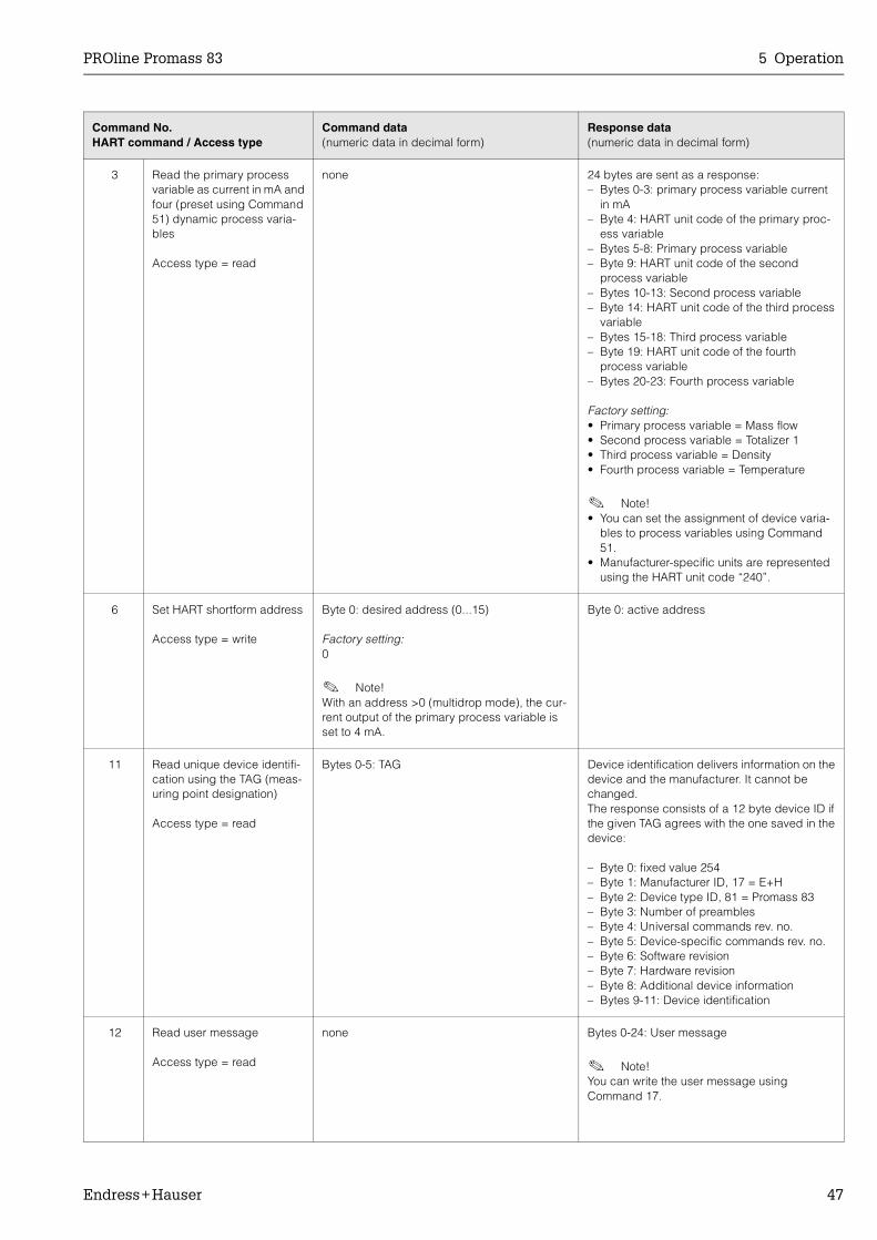
3 Read the primary process variable as current in mA and four (preset using Command 51) dynamic process varia-bles
Access type = read
none 24 bytes are sent as a response:– Bytes 0-3: primary process variable current
in mA– Byte 4: HART unit code of the primary proc-
ess variable– Bytes 5-8: Primary process variable– Byte 9: HART unit code of the second
process variable– Bytes 10-13: Second process variable– Byte 14: HART unit code of the third process
variable– Bytes 15-18: Third process variable– Byte 19: HART unit code of the fourth
process variable– Bytes 20-23: Fourth process variable
Factory setting:• Primary process variable = Mass flow• Second process variable = Totalizer 1• Third process variable = Density• Fourth process variable = Temperature
! Note!• You can set the assignment of device varia-
bles to process variables using Command 51.
• Manufacturer-specific units are represented using the HART unit code “240”.
6 Set HART shortform address
Access type = write
Byte 0: desired address (0...15)
Factory setting:0
! Note!With an address >0 (multidrop mode), the cur-rent output of the primary process variable is set to 4 mA.
Byte 0: active address
11 Read unique device identifi-cation using the TAG (meas-uring point designation)
Access type = read
Bytes 0-5: TAG Device identification delivers information on the device and the manufacturer. It cannot be changed. The response consists of a 12 byte device ID if the given TAG agrees with the one saved in the device:
– Byte 0: fixed value 254– Byte 1: Manufacturer ID, 17 = E+H– Byte 2: Device type ID, 81 = Promass 83– Byte 3: Number of preambles– Byte 4: Universal commands rev. no.– Byte 5: Device-specific commands rev. no.– Byte 6: Software revision– Byte 7: Hardware revision– Byte 8: Additional device information– Bytes 9-11: Device identification
12 Read user message
Access type = read
none Bytes 0-24: User message
! Note!You can write the user message using Command 17.
Command No.HART command / Access type
Command data(numeric data in decimal form)
Response data(numeric data in decimal form)
5 Operation PROline Promass 83
48 Endress+Hauser
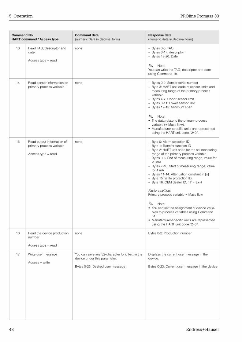
13 Read TAG, descriptor and date
Access type = read
none – Bytes 0-5: TAG– Bytes 6-17: descriptor– Bytes 18-20: Date
! Note!You can write the TAG, descriptor and date using Command 18.
14 Read sensor information on primary process variable
none – Bytes 0-2: Sensor serial number– Byte 3: HART unit code of sensor limits and
measuring range of the primary process variable
– Bytes 4-7: Upper sensor limit– Bytes 8-11: Lower sensor limit– Bytes 12-15: Minimum span
! Note!• The data relate to the primary process
variable (= Mass flow).• Manufacturer-specific units are represented
using the HART unit code “240”.
15 Read output information of primary process variable
Access type = read
none – Byte 0: Alarm selection ID– Byte 1: Transfer function ID– Byte 2: HART unit code for the set measuring
range of the primary process variable– Bytes 3-6: End of measuring range, value for
20 mA– Bytes 7-10: Start of measuring range, value
for 4 mA– Bytes 11-14: Attenuation constant in [s]– Byte 15: Write protection ID– Byte 16: OEM dealer ID, 17 = E+H
Factory setting:Primary process variable = Mass flow
! Note!• You can set the assignment of device varia-
bles to process variables using Command 51.
• Manufacturer-specific units are represented using the HART unit code “240”.
16 Read the device production number
Access type = read
none Bytes 0-2: Production number
17 Write user message
Access = write
You can save any 32-character long text in the device under this parameter:
Bytes 0-23: Desired user message
Displays the current user message in the device:
Bytes 0-23: Current user message in the device
Command No.HART command / Access type
Command data(numeric data in decimal form)
Response data(numeric data in decimal form)
PROline Promass 83 5 Operation
Endress+Hauser 49
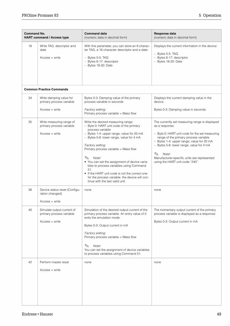
18 Write TAG, descriptor and date
Access = write
With this parameter, you can store an 8 charac-ter TAG, a 16 character descriptor and a date:
– Bytes 0-5: TAG– Bytes 6-17: descriptor– Bytes 18-20: Date
Displays the current information in the device:
– Bytes 0-5: TAG– Bytes 6-17: descriptor– Bytes 18-20: Date
Common Practice Commands
34 Write damping value for primary process variable
Access = write
Bytes 0-3: Damping value of the primary process variable in seconds
Factory setting:Primary process variable = Mass flow
Displays the current damping value in the device:
Bytes 0-3: Damping value in seconds
35 Write measuring range of primary process variable
Access = write
Write the desired measuring range:– Byte 0: HART unit code of the primary
process variable– Bytes 1-4: upper range, value for 20 mA– Bytes 5-8: lower range, value for 4 mA
Factory setting:Primary process variable = Mass flow
! Note!• You can set the assignment of device varia-
bles to process variables using Command 51.
• If the HART unit code is not the correct one for the process variable, the device will con-tinue with the last valid unit.
The currently set measuring range is displayed as a response:
– Byte 0: HART unit code for the set measuring range of the primary process variable
– Bytes 1-4: upper range, value for 20 mA– Bytes 5-8: lower range, value for 4 mA
! Note!Manufacturer-specific units are represented using the HART unit code “240”.
38 Device status reset (Configu-ration changed)
Access = write
none none
40 Simulate output current of primary process variable
Access = write
Simulation of the desired output current of the primary process variable. An entry value of 0 exits the simulation mode:
Bytes 0-3: Output current in mA
Factory setting:Primary process variable = Mass flow
! Note!You can set the assignment of device variables to process variables using Command 51.
The momentary output current of the primary process variable is displayed as a response:
Bytes 0-3: Output current in mA
42 Perform master reset
Access = write
none none
Command No.HART command / Access type
Command data(numeric data in decimal form)
Response data(numeric data in decimal form)

5 Operation PROline Promass 83
50 Endress+Hauser
44 Write unit of primary process variable
Access = write
Set unit of primary process variable. Only unit which are suitable for the process variable are transferred to the device:
Byte 0: HART unit code
Factory setting:Primary process variable = Mass flow
! Note!• If the written HART unit code is not the cor-
rect one for the process variable, the device will continue with the last valid unit.
• If you change the unit of the primary process variable, this has no impact on the system units.
The current unit code of the primary process variable is displayed as a response:
Byte 0: HART unit code
! Note!Manufacturer-specific units are represented using the HART unit code “240”.
48 Read additional device status
Access = read
none The device status is displayed in extended form as the response:
Coding: see table on Page 52
50 Read assignment of the device variables to the four process variables
Access = read
none Display of the current variable assignment of the process variables:
– Byte 0: Device variable code to the primary process variable
– Byte 1: Device variable code to the second process variable
– Byte 2: Device variable code to the third process variable
– Byte 3: Device variable code to the fourth process variable
Factory setting:• Primary process variable: Code 1 for mass
flow • Second process variable: Code 250 for
totalizer 1• Third process variable: Code 2 for density• Fourth process variable: Code 0 for
temperature
! Note!You can set or change the assignment of device variables to process variables using Command 51.
Command No.HART command / Access type
Command data(numeric data in decimal form)
Response data(numeric data in decimal form)
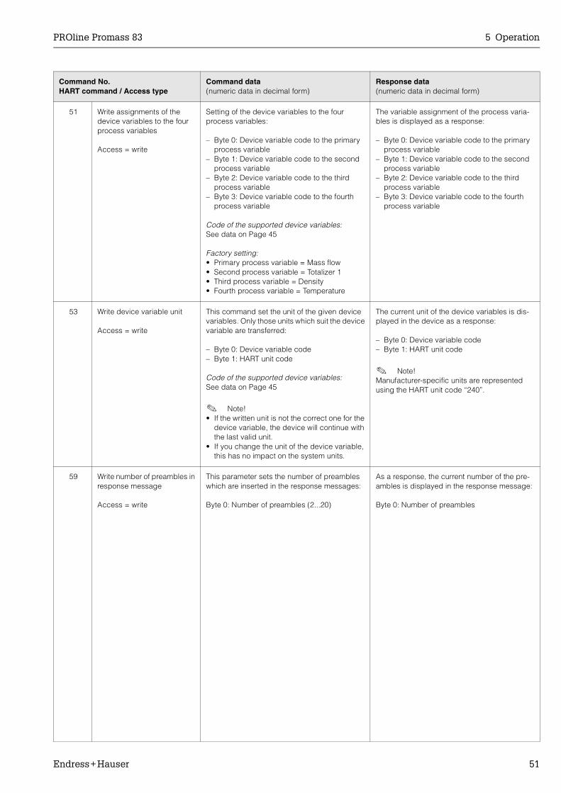
PROline Promass 83 5 Operation
Endress+Hauser 51
51 Write assignments of the device variables to the four process variables
Access = write
Setting of the device variables to the four process variables:
– Byte 0: Device variable code to the primary process variable
– Byte 1: Device variable code to the second process variable
– Byte 2: Device variable code to the third process variable
– Byte 3: Device variable code to the fourth process variable
Code of the supported device variables:See data on Page 45
Factory setting:• Primary process variable = Mass flow• Second process variable = Totalizer 1• Third process variable = Density• Fourth process variable = Temperature
The variable assignment of the process varia-bles is displayed as a response:
– Byte 0: Device variable code to the primary process variable
– Byte 1: Device variable code to the second process variable
– Byte 2: Device variable code to the third process variable
– Byte 3: Device variable code to the fourth process variable
53 Write device variable unit
Access = write
This command set the unit of the given device variables. Only those units which suit the device variable are transferred:
– Byte 0: Device variable code– Byte 1: HART unit code
Code of the supported device variables:See data on Page 45
! Note!• If the written unit is not the correct one for the
device variable, the device will continue with the last valid unit.
• If you change the unit of the device variable, this has no impact on the system units.
The current unit of the device variables is dis-played in the device as a response:
– Byte 0: Device variable code– Byte 1: HART unit code
! Note!Manufacturer-specific units are represented using the HART unit code “240”.
59 Write number of preambles in response message
Access = write
This parameter sets the number of preambles which are inserted in the response messages:
Byte 0: Number of preambles (2...20)
As a response, the current number of the pre-ambles is displayed in the response message:
Byte 0: Number of preambles
Command No.HART command / Access type
Command data(numeric data in decimal form)
Response data(numeric data in decimal form)
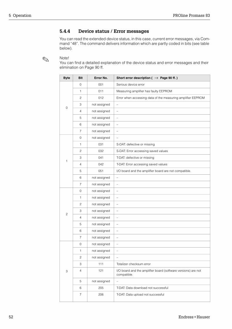
5 Operation PROline Promass 83
52 Endress+Hauser
5.4.4 Device status / Error messages
You can read the extended device status, in this case, current error messages, via Com-mand “48”. The command delivers information which are partly coded in bits (see table below).
! Note!You can find a detailed explanation of the device status and error messages and their elimination on Page 90 ff.
Byte Bit Error No. Short error description ( → Page 90 ff. )
0
0 001 Serious device error
1 011 Measuring amplifier has faulty EEPROM
2 012 Error when accessing data of the measuring amplifier EEPROM
3 not assigned –
4 not assigned –
5 not assigned –
6 not assigned –
7 not assigned –
1
0 not assigned –
1 031 S-DAT: defective or missing
2 032 S-DAT: Error accessing saved values
3 041 T-DAT: defective or missing
4 042 T-DAT: Error accessing saved values
5 051 I/O board and the amplifier board are not compatible.
6 not assigned –
7 not assigned –
2
0 not assigned –
1 not assigned –
2 not assigned –
3 not assigned –
4 not assigned –
5 not assigned –
6 not assigned –
7 not assigned –
3
0 not assigned –
1 not assigned –
2 not assigned –
3 111 Totalizer checksum error
4 121 I/O board and the amplifier board (software versions) are not compatible.
5 not assigned –
6 205 T-DAT: Data download not successful
7 206 T-DAT: Data upload not successful
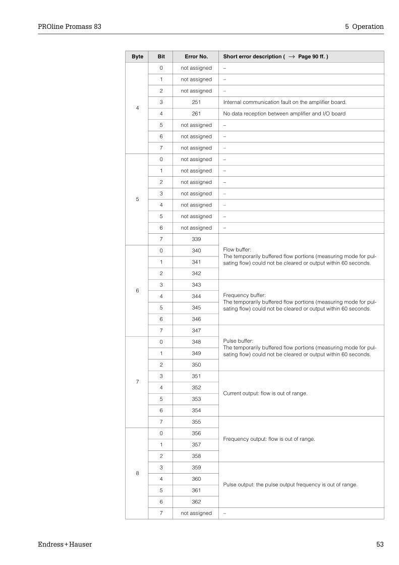
PROline Promass 83 5 Operation
Endress+Hauser 53
4
0 not assigned –
1 not assigned –
2 not assigned –
3 251 Internal communication fault on the amplifier board.
4 261 No data reception between amplifier and I/O board
5 not assigned –
6 not assigned –
7 not assigned –
5
0 not assigned –
1 not assigned –
2 not assigned –
3 not assigned –
4 not assigned –
5 not assigned –
6 not assigned –
7 339
Flow buffer: The temporarily buffered flow portions (measuring mode for pul-sating flow) could not be cleared or output within 60 seconds.
6
0 340
1 341
2 342
3 343
Frequency buffer: The temporarily buffered flow portions (measuring mode for pul-sating flow) could not be cleared or output within 60 seconds.
4 344
5 345
6 346
7 347
Pulse buffer: The temporarily buffered flow portions (measuring mode for pul-sating flow) could not be cleared or output within 60 seconds.
7
0 348
1 349
2 350
3 351
Current output: flow is out of range.4 352
5 353
6 354
7 355
Frequency output: flow is out of range.
8
0 356
1 357
2 358
3 359
Pulse output: the pulse output frequency is out of range.4 360
5 361
6 362
7 not assigned –
Byte Bit Error No. Short error description ( → Page 90 ff. )

5 Operation PROline Promass 83
54 Endress+Hauser
9
0 379 The measuring tube oscillation frequency is outside the permitted range.1 380
2 381 The temperature sensor on the measuring tube is likely defective.
3 382 The temperature sensor on the measuring tube is likely defective.
4 383The temperature sensor on the carrier tube is likely defective.
5 384
6 385
One of the measuring tube exciter coils (inlet or outlet) is likely defective.
7 386
10
0 387
1 388
Amplifier error2 389
3 390
4 not assigned –
5 not assigned –
6 not assigned –
7 not assigned –
11
0 not assigned –
1 not assigned –
2 not assigned –
3 not assigned –
4 not assigned –
5 not assigned –
6 471 Max. permitted batching time has been exceeded.
7 472 Underbatching: the minimum quantity was not reached.Overbatching: the maximum permitted batching quantity was exceeded.
12
0 473 The predefined batch quantity point was exceeded. End of filling process approaching.
1 not assigned –
2 not assigned –
3 not assigned –
4 not assigned –
5 not assigned –
6 not assigned –
7 501 New amplifier software version is loaded.Currently no other commands are possible.
Byte Bit Error No. Short error description ( → Page 90 ff. )
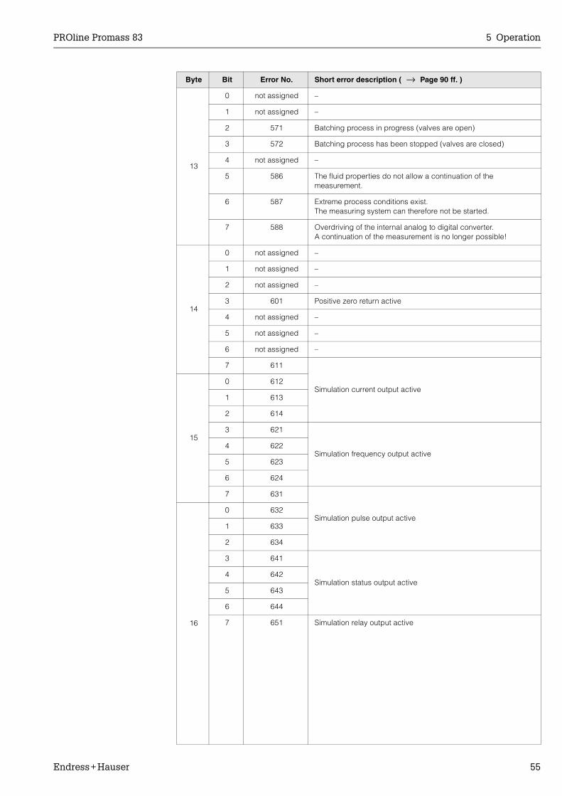
PROline Promass 83 5 Operation
Endress+Hauser 55
13
0 not assigned –
1 not assigned –
2 571 Batching process in progress (valves are open)
3 572 Batching process has been stopped (valves are closed)
4 not assigned –
5 586 The fluid properties do not allow a continuation of the measurement.
6 587 Extreme process conditions exist. The measuring system can therefore not be started.
7 588 Overdriving of the internal analog to digital converter. A continuation of the measurement is no longer possible!
14
0 not assigned –
1 not assigned –
2 not assigned –
3 601 Positive zero return active
4 not assigned –
5 not assigned –
6 not assigned –
7 611
Simulation current output active
15
0 612
1 613
2 614
3 621
Simulation frequency output active4 622
5 623
6 624
7 631
Simulation pulse output active
16
0 632
1 633
2 634
3 641
Simulation status output active4 642
5 643
6 644
7 651 Simulation relay output active
Byte Bit Error No. Short error description ( → Page 90 ff. )
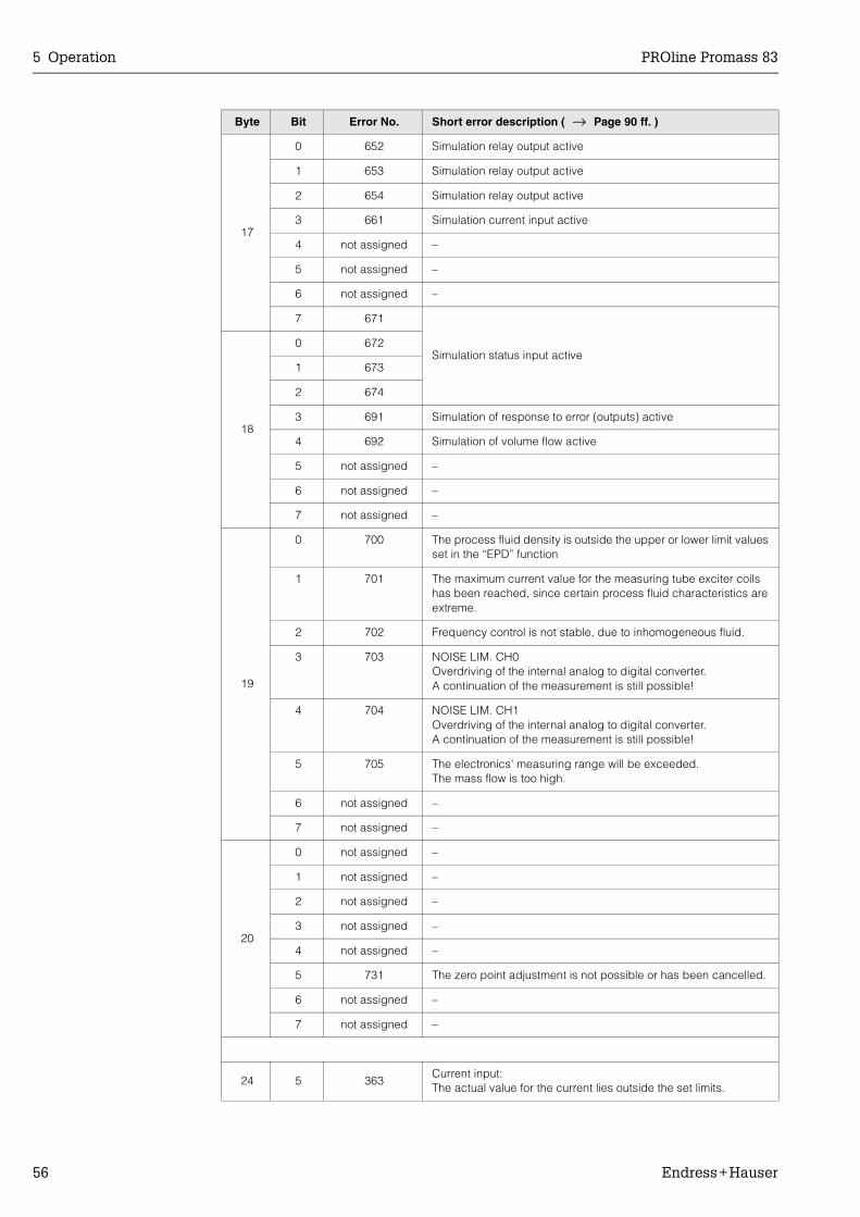
5 Operation PROline Promass 83
56 Endress+Hauser
17
0 652 Simulation relay output active
1 653 Simulation relay output active
2 654 Simulation relay output active
3 661 Simulation current input active
4 not assigned –
5 not assigned –
6 not assigned –
7 671
Simulation status input active
18
0 672
1 673
2 674
3 691 Simulation of response to error (outputs) active
4 692 Simulation of volume flow active
5 not assigned –
6 not assigned –
7 not assigned –
19
0 700 The process fluid density is outside the upper or lower limit values set in the “EPD” function
1 701 The maximum current value for the measuring tube exciter coils has been reached, since certain process fluid characteristics are extreme.
2 702 Frequency control is not stable, due to inhomogeneous fluid.
3 703 NOISE LIM. CH0Overdriving of the internal analog to digital converter.A continuation of the measurement is still possible!
4 704 NOISE LIM. CH1Overdriving of the internal analog to digital converter.A continuation of the measurement is still possible!
5 705 The electronics' measuring range will be exceeded. The mass flow is too high.
6 not assigned –
7 not assigned –
20
0 not assigned –
1 not assigned –
2 not assigned –
3 not assigned –
4 not assigned –
5 731 The zero point adjustment is not possible or has been cancelled.
6 not assigned –
7 not assigned –
24 5 363Current input:The actual value for the current lies outside the set limits.
Byte Bit Error No. Short error description ( → Page 90 ff. )
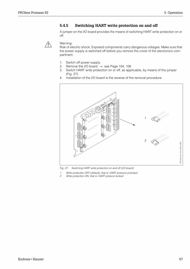
PROline Promass 83 5 Operation
Endress+Hauser 57
5.4.5 Switching HART write protection on and off
A jumper on the I/O board provides the means of switching HART write protection on or off.
# Warning:Risk of electric shock. Exposed components carry dangerous voltages. Make sure that the power supply is switched off before you remove the cover of the electronics com-partment.
1. Switch off power supply.2. Remove the I/O board → see Page 104, 1063. Switch HART write protection on or off, as applicable, by means of the jumper
(Fig. 27).4. Installation of the I/O board is the reverse of the removal procedure.
Fig. 27: Switching HART write protection on and off (I/O board)
1 Write protection OFF (default), that is: HART protocol unlocked2 Write protection ON, that is: HART protocol locked
F06-
x3xx
xxxx
-16-
xx-0
6-xx
-000

5 Operation PROline Promass 83
58 Endress+Hauser
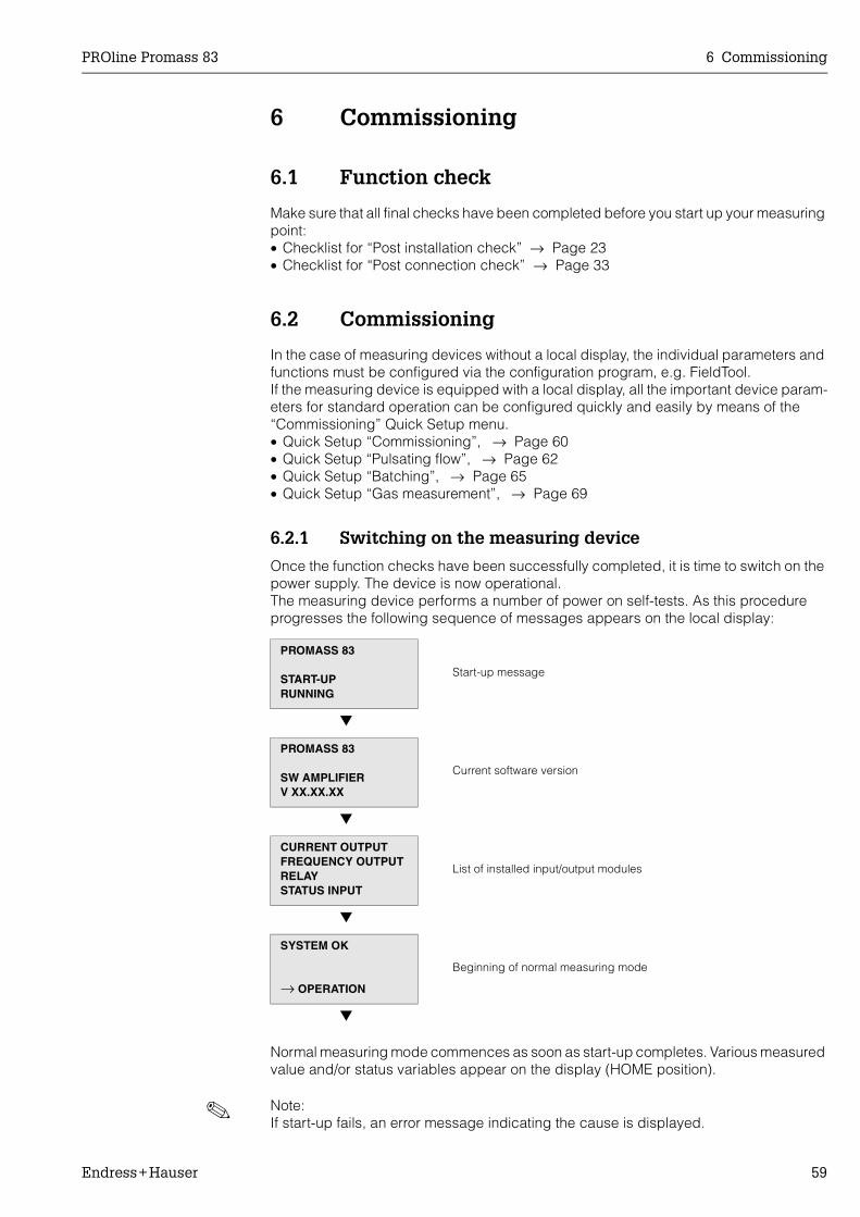
PROline Promass 83 6 Commissioning
Endress+Hauser 59
6 Commissioning
6.1 Function check
Make sure that all final checks have been completed before you start up your measuring point:• Checklist for “Post installation check” → Page 23• Checklist for “Post connection check” → Page 33
6.2 Commissioning
In the case of measuring devices without a local display, the individual parameters and functions must be configured via the configuration program, e.g. FieldTool.If the measuring device is equipped with a local display, all the important device param-eters for standard operation can be configured quickly and easily by means of the “Commissioning” Quick Setup menu.• Quick Setup “Commissioning”, → Page 60• Quick Setup “Pulsating flow”, → Page 62• Quick Setup “Batching”, → Page 65• Quick Setup “Gas measurement”, → Page 69
6.2.1 Switching on the measuring device
Once the function checks have been successfully completed, it is time to switch on the power supply. The device is now operational. The measuring device performs a number of power on self-tests. As this procedure progresses the following sequence of messages appears on the local display:
Normal measuring mode commences as soon as start-up completes. Various measured value and/or status variables appear on the display (HOME position).
! Note:If start-up fails, an error message indicating the cause is displayed.
PROMASS 83
START-UPRUNNING
Start-up message
PROMASS 83
SW AMPLIFIERV XX.XX.XX
Current software version
CURRENT OUTPUTFREQUENCY OUTPUTRELAYSTATUS INPUT
List of installed input/output modules
SYSTEM OK
→ OPERATION
Beginning of normal measuring mode

6 Commissioning PROline Promass 83
60 Endress+Hauser
6.2.2 Quick Setup “Commissioning”
This Quick Setup menu guides you systematically through the setup procedure for all the major device functions that have to be configured for standard measuring operation.
Fig. 28: Quick Setup menu for straightforward configuration of the major device functions
Information on the points numbered in the Quick Setup can be found on the following page.
04200400
6461
0421 6462
6463
6464
4200
4221
4222
4223
4225
4227
4226
4000
4001
4002
4004
4006
4003
4005
4201
4203
4204
4206
4208
4209
4205
4207
0422
646030013001
04040402
2000
1002B++ +E E
- +
ENDRESS+HAUSER
E
ESC
Batching
Yes
Yes
Yes
No
No
No
No
Configure another system unit ?
Current output n Freq./Pulse output n
Selection output type
Automatic configuration of display ?
Carrying out another Quick Setup ?
Quit
AssignCurrent output
Current span
Value 0/4 mA
Value 20 mA
Meas. mode Meas. mode
Meas. mode
Time constant
Time constantFailsafe mode
Failsafe mode
Failsafe mode
AssignFreq. output
End value freq.
Value F Low
Value F High
Output signal
AssignPulse output
Pulse value
Pulse width
Output signal
Operation Mode
Frequency Pulse
Automatic parameterization of the display
Reference Calculated
Fix. Density
Density
UnitRef. Density Exp. Coeff. Lin
Exp. Coeff. SQR
Reference temp.
Volume flow Corr. Vol. flowMass flow Density
Selection system units
Temperature Quit
UnitVolume flow
UnitCorr. Vol. flow
UnitMass flow
UnitDensity
UnitTemperature
UnitTotalizer
Corr. Vol.calculation
UnitTotalizer
Language
Pre-setting
Quick Setup
HOME-POSITION
QSCommission
Pulsating flow Gas measurement
Configure another output ?
Carrying out the selected Quick Setup
F06-
83xx
xxxx
-19-
xx-x
x-en
-000

PROline Promass 83 6 Commissioning
Endress+Hauser 61
! Note:• The display returns to the cell QUICK SETUP COMMISSION (1002) if you press the
ESC key combination during parameter interrogation. The stored parameters remain valid.
• The “Commissioning” Quick Setup must be carried out before one of the Quick Setups explained below is run.
• ➀ Only units not yet configured in the current Setup are offered for selection in eachcycle. The unit for mass, volume and corrected volume is derived from the corresponding flow unit.
• ➁ The “YES” option remains visible until all the units have been configured.“NO” is the only option displayed when no further units are available.
• ➂ Only the outputs not yet configured in the current Setup are offered for selection ineach cycle.
• ➃ The “YES” option remains visible until all the outputs have been parameterized. “NO” is the only option displayed when no further outputs are available.
• ➄ The “automatic parameterization of the display” option contains the following basicsettings/factory settings:YES: Main line = Mass flow; Additional line = Totalizer 1; Information line = Operating/system conditions.NO: The existing (selected) settings remain.
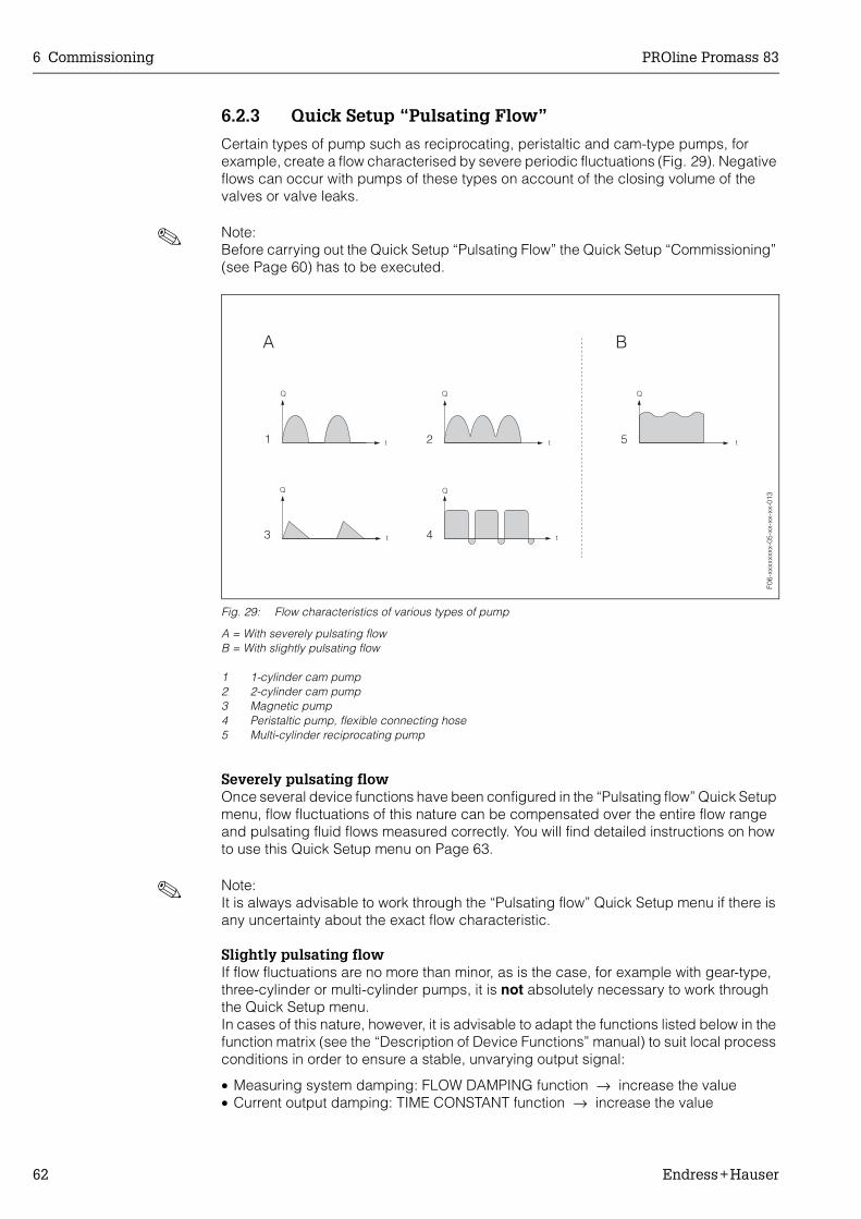
6 Commissioning PROline Promass 83
62 Endress+Hauser
6.2.3 Quick Setup “Pulsating Flow”
Certain types of pump such as reciprocating, peristaltic and cam-type pumps, for example, create a flow characterised by severe periodic fluctuations (Fig. 29). Negative flows can occur with pumps of these types on account of the closing volume of the valves or valve leaks.
! Note:Before carrying out the Quick Setup “Pulsating Flow” the Quick Setup “Commissioning” (see Page 60) has to be executed.
Fig. 29: Flow characteristics of various types of pump
A = With severely pulsating flowB = With slightly pulsating flow
1 1-cylinder cam pump2 2-cylinder cam pump3 Magnetic pump4 Peristaltic pump, flexible connecting hose5 Multi-cylinder reciprocating pump
Severely pulsating flowOnce several device functions have been configured in the “Pulsating flow” Quick Setup menu, flow fluctuations of this nature can be compensated over the entire flow range and pulsating fluid flows measured correctly. You will find detailed instructions on how to use this Quick Setup menu on Page 63.
! Note:It is always advisable to work through the “Pulsating flow” Quick Setup menu if there is any uncertainty about the exact flow characteristic.
Slightly pulsating flowIf flow fluctuations are no more than minor, as is the case, for example with gear-type, three-cylinder or multi-cylinder pumps, it is not absolutely necessary to work through the Quick Setup menu. In cases of this nature, however, it is advisable to adapt the functions listed below in the function matrix (see the “Description of Device Functions” manual) to suit local process conditions in order to ensure a stable, unvarying output signal:
• Measuring system damping: FLOW DAMPING function → increase the value• Current output damping: TIME CONSTANT function → increase the value
F06-
xxxx
xxxx
-05-
xx-x
x-xx
-013

PROline Promass 83 6 Commissioning
Endress+Hauser 63
Performing the “Pulsating flow” Quick SetupThis Quick Setup menu guides you systematically through the setup procedure for all the device functions that have to be parameterised and configured for measuring pul-sating flows. Note that this has no effect on values configured beforehand, such as measuring range, current range or full scale value.
Fig. 30: Quick Setup for measuring severely pulsating flowsRecommended settings → see next page
++E- +
ENDRESS+HAUSER
E
ESC
+E
3002 3002 3002
4200
4225
8005
6400
6402
6403
6404
4206
4208
4004
4005
B
2002
1003
Yes
Yes
No
No
➁ Configure another totalizer ?
➂
Current output n Freq.-/Puse output n
Selection of output type
Quit
➀
Totalizer 2Totalizer 1 Totalizer 3
Selection totalizer
Quit
Totalizermode (DAA)
Totalizermode (DAB)
Totalizermode (DAC)
Frequency Pulse
Operation mode
Measuring mode
Alarm delay
AssignLF-Cut off
On-valueLF-Cut off
Off-valueLF-Cut off
Pressureshock suppression
QuitQuick Setup
Measuring mode
Time constant
Measuring mode
Time constant
Quick Setup
HOME-POSITION
Displaydamping
QSPlusating Flow
➃ Configure another output ?
F06-
83xx
xxxx
-19-
xx-x
x-en
-001
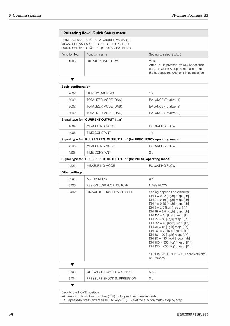
6 Commissioning PROline Promass 83
64 Endress+Hauser
“Pulsating flow” Quick Setup menu
HOME position → F → MEASURED VARIABLEMEASURED VARIABLE → O → QUICK SETUPQUICK SETUP → N → QS PULSATING FLOW
Function No. Function name Setting to select ( OS )
1003 QS PULSATING FLOW YESAfter F is pressed by way of confirma-tion, the Quick Setup menu calls up all the subsequent functions in succession.
Basic configuration
2002 DISPLAY DAMPING 1 s
3002 TOTALIZER MODE (DAA) BALANCE (Totalizer 1)
3002 TOTALIZER MODE (DAB) BALANCE (Totalizer 2)
3002 TOTALIZER MODE (DAC) BALANCE (Totalizer 3)
Signal type for “CURRENT OUTPUT 1...n”
4004 MEASURING MODE PULSATING FLOW
4005 TIME CONSTANT 1 s
Signal type for “PULSE/FREQ. OUTPUT 1...n” (for FREQUENCY operating mode)
4206 MEASURING MODE PULSATING FLOW
4208 TIME CONSTANT 0 s
Signal type for “PULSE/FREQ. OUTPUT 1...n” (for PULSE operating mode)
4225 MEASURING MODE PULSATING FLOW
Other settings
8005 ALARM DELAY 0 s
6400 ASSIGN LOW FLOW CUTOFF MASS FLOW
6402 ON-VALUE LOW FLOW CUT OFF Setting depends on diameter:DN 1 = 0.02 [kg/h] resp. [l/h]DN 2 = 0.10 [kg/h] resp. [l/h]DN 4 = 0.45 [kg/h] resp. [l/h]DN 8 = 2.0 [kg/h] resp. [l/h]DN 15 = 6.5 [kg/h] resp. [l/h]DN 15* = 18 [kg/h] resp. [l/h]DN 25 = 18 [kg/h] resp. [l/h]DN 25* = 45 [kg/h] resp. [l/h]DN 40 = 45 [kg/h] resp. [l/h]DN 40* = 70 [kg/h] resp. [l/h]DN 50 = 70 [kg/h] resp. [l/h]DN 80 = 180 [kg/h] resp. [l/h]DN 100 = 350 [kg/h] resp. [l/h]DN 150 = 650 [kg/h] resp. [l/h]
* DN 15, 25, 40 “FB” = Full bore versions of Promass I
6403 OFF-VALUE LOW FLOW CUTOFF 50%
6404 PRESSURE SHOCK SUPPRESSION 0 s
Back to the HOME position→ Press and hold down Esc key (X) for longer than three seconds.→ Repeatedly press and release Esc key (X) → exit the function matrix step by step

PROline Promass 83 6 Commissioning
Endress+Hauser 65
6.2.4 Quick Setup “Batching”
This Quick Setup menu guides you systematically through the setup procedure for all the device functions that have to be parameterised and configured for batching opera-tion. These basic settings allow simple (one step) batching processes.Additional settings, e.g. for the calculation of after runs or for multi-stage batching procedures, must be made via the function matrix itself (see the “Description of Device Functions” manual).
! Note!• Before carrying out the Quick Setup “Batching” the Quick Setup “Commissioning”
(see Page 60) has to be executed.• This function is only available when the additional “batching” software is installed in
the measuring device (order option). You can order this software from E+H as an accessory at a later date (see Page 87).
• You can find detailed information on the batching functions in the separate “Descrip-tion of Device Functions” manual.
• You can also directly control filling process using the local display. During Quick Setup, an appropriate dialogue appears concerning the automatic display configura-tion. Exit this by clicking “YES”.This assigns special batching functions (START, PRESET, MATRIX) to the bottom line of the display. These can be directly executed on-site using the three operating keys (–/+/E). Therefore, Promass 83 can be fully deployed in the field as a “batch controller” → Page 39.
" Caution!The “Batching” Quick Setup sets certain device parameters for discontinuous measure-ment operation. If the measuring instrument is used for continuous flow measurement at a later time, we recommend at you rerun the “Commissioning” and/or “Pulsating Flow” Quick Setup.

6 Commissioning PROline Promass 83
66 Endress+Hauser
Fig. 31: “Batching” Quick Setup for configuration of batching functionsRecommended settings → see next page
++E- +
ENDRESS+HAUSER
E
ESC
+E
B
6402
6603
6404
7200
7201
7203
7204
4700
4780
1005
7240
HOME-POSITION
ON-ValueLow flow cut off
Flowdamping
Pressure shocksuppression
BatchSelector
BatchName
BatchQuantity
FixCompensation Quantity
AssignRelay
Terminal No.
Max. BatchTime
QSBatching/Dosing
YES NOBatch
Supervision?
YES NOAutom. Configuration
Display?
Locked Access CustomerPRESET
Batch quantity
Automatic parameterizationof the display
Quick Setup
Quit Quick Setup
F06-
83xx
xxxx
-19-
xx-x
x-en
-004

PROline Promass 83 6 Commissioning
Endress+Hauser 67
“Batching” Quick Setup menu
HOME position → F → MEASURED VARIABLE (A)MEASURED VARIABLE → O → QUICK SETUP (B)QUICK SETUP → N → QUICK SETUP BATCHING / DOSING (1005)
Function No. Function name Setting to select ( OS )(Go to next function: press F )
1005 QUICK SETUP BATCHING / DOSING YESAfter F is pressed by way of confirma-tion, the Quick Setup menu calls up all the sub-sequent functions in succession.
! Warning:Some of the functions listed below (with a grey background) are configured automatically, i.e. by the measuring system.
6400 ASSIGN LOW FLOW CUTOFF MASS FLOW
6402 ON-VALUE LOW FLOW CUTOFF see Table on Page 68
6403 OFF-VALUE LOW FLOW CUTOFF 50%
6603 FLOW DAMPING 0 seconds
6404 PRESSURE SHOCK SUPPRESSION 0 seconds
7200 BATCH SELECTOR BATCH #1
7201 BATCH NAME BATCH #1
7202 ASSIGN BATCH VARIABLE MASS
7203 BATCH QUANTITY 0 [unit]
7204 FIX COMPENSATION QUANTITY 0 [unit]
7205 COMPENSATION MODE OFF
7208 BATCH STAGES 1
7209 INPUT FORMAT Value input
4700 ASSIGN RELAY BATCH VALVE 1
4780 TERMINAL NUMBER Output (display only)
7220 OPEN VALVE 1 0% or 0 [unit]
7240 MAXIMUM BATCH TIME 0 seconds (= switched off)
7241 MINIMUM BATCH QUANTITY 0
7242 MAXIMUM BATCH QUANTITY 0
2200 ASSIGN (main line) BATCH NAME
2220 ASSIGN (multiplex main line) OFF
2400 ASSIGN (addition line) BATCH DOWNWARDS
2420 ASSIGN (multiplex addition line) OFF
2600 ASSIGN (information line) BATCHING KEYS
2620 ASSIGN (multiplex information line) OFF
Back to the HOME position→ Press and hold down Esc key (X) for longer than three seconds.→ Repeatedly press and release Esc key (X) → exit the function matrix step by step
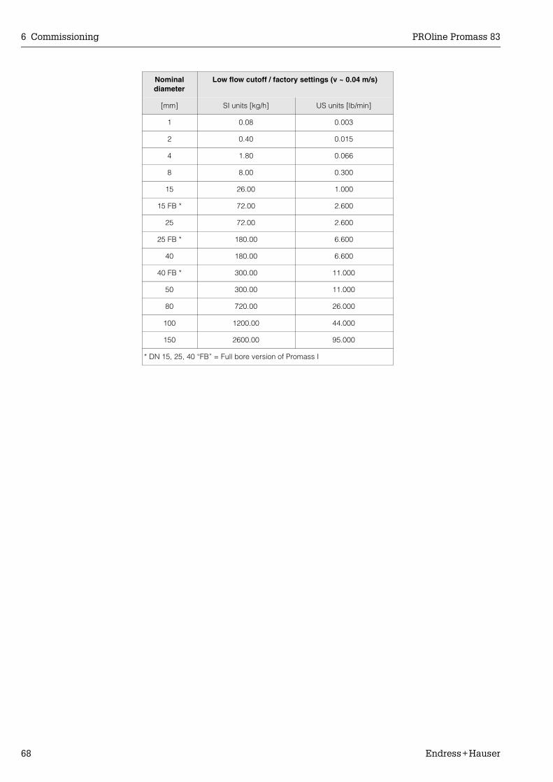
6 Commissioning PROline Promass 83
68 Endress+Hauser
Nominal diameter
Low flow cutoff / factory settings (v ~ 0.04 m/s)
[mm] SI units [kg/h] US units [lb/min]
1 0.08 0.003
2 0.40 0.015
4 1.80 0.066
8 8.00 0.300
15 26.00 1.000
15 FB * 72.00 2.600
25 72.00 2.600
25 FB * 180.00 6.600
40 180.00 6.600
40 FB * 300.00 11.000
50 300.00 11.000
80 720.00 26.000
100 1200.00 44.000
150 2600.00 95.000
* DN 15, 25, 40 “FB” = Full bore version of Promass I

PROline Promass 83 6 Commissioning
Endress+Hauser 69
6.2.5 Quick Setup “Gas Measurement”
Promass 83 is not only suitable for measuring liquid flow. Direct mass measurement based on the Coriolis principle is also possible for measuring the flow rate of gases.
! Note:• Before carrying out the Quick Setup “Gas Measurement” the Quick Setup “Commis-
sioning” (see Page 60) has to be executed.• Only mass and Corrected volume flow can be measured and output with the gas
measurement mode. Note that direct density and/or volume measurement is not possible!
• The flow ranges and measuring accuracy that apply to gas measurement are not the same as those for liquids.
• If Corrected volume flow (e.g. in Nm3/h) is to be measured and output instead of the mass flow (e.g. in kg/h), change the setting for the CORRECTED VOLUME CALCU-LATION function to “FIXED REFERENCE DENSITY” in the “Commissioning” Quick Setup menu. Corrected volume flow can be assigned as follows:– to a display line– to the current output– to the pulse/frequency output
Performing the “Gas Measurement” Quick SetupThis Quick Setup menu guides you systematically through the setup procedure for all the device functions that have to be parameterised and configured for gas measure-ment.
Fig. 32: Quick Setup for measuring gases. Recommended settings → see next page
++E- +
ENDRESS+HAUSER
E
ESC
+E
BQuick SetupQuick Setup
6400
6402
6403
1004
HOME-POSITION
AssignLow flow cut off
On-valueLow flow cut off
Off-valueLow flow cut off
QSGas measurement
F06-
83xx
xxxx
-19-
xx-x
x-en
-002
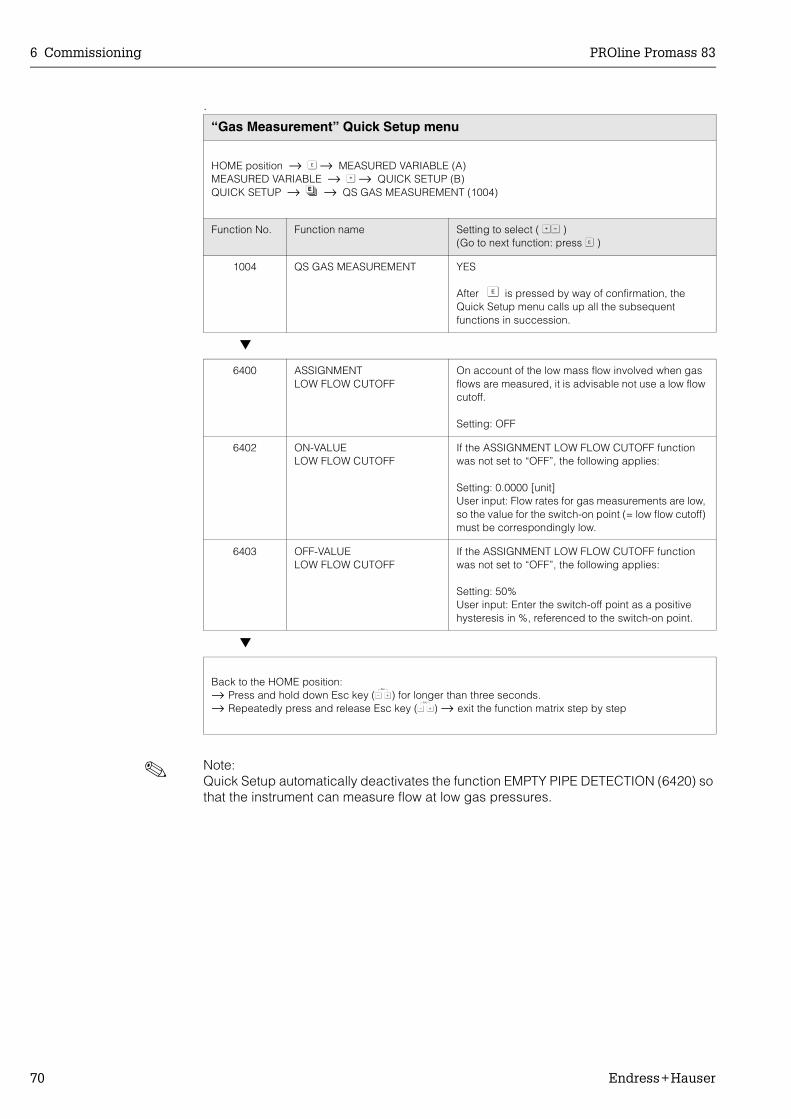
6 Commissioning PROline Promass 83
70 Endress+Hauser
.
! Note:Quick Setup automatically deactivates the function EMPTY PIPE DETECTION (6420) so that the instrument can measure flow at low gas pressures.
“Gas Measurement” Quick Setup menu
HOME position → F → MEASURED VARIABLE (A)MEASURED VARIABLE → O → QUICK SETUP (B)QUICK SETUP → N → QS GAS MEASUREMENT (1004)
Function No. Function name Setting to select ( OS )(Go to next function: press F )
1004 QS GAS MEASUREMENT YES
After F is pressed by way of confirmation, the Quick Setup menu calls up all the subsequent functions in succession.
6400 ASSIGNMENTLOW FLOW CUTOFF
On account of the low mass flow involved when gas flows are measured, it is advisable not use a low flow cutoff.
Setting: OFF
6402 ON-VALUELOW FLOW CUTOFF
If the ASSIGNMENT LOW FLOW CUTOFF function was not set to “OFF”, the following applies:
Setting: 0.0000 [unit]User input: Flow rates for gas measurements are low, so the value for the switch-on point (= low flow cutoff) must be correspondingly low.
6403 OFF-VALUELOW FLOW CUTOFF
If the ASSIGNMENT LOW FLOW CUTOFF function was not set to “OFF”, the following applies:
Setting: 50%User input: Enter the switch-off point as a positive hysteresis in %, referenced to the switch-on point.
Back to the HOME position:→ Press and hold down Esc key (X) for longer than three seconds.→ Repeatedly press and release Esc key (X) → exit the function matrix step by step
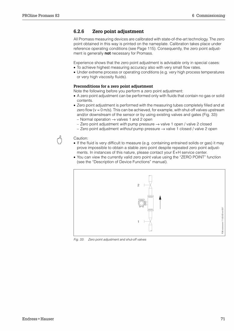
PROline Promass 83 6 Commissioning
Endress+Hauser 71
6.2.6 Zero point adjustment
All Promass measuring devices are calibrated with state-of-the-art technology. The zero point obtained in this way is printed on the nameplate. Calibration takes place under reference operating conditions (see Page 115). Consequently, the zero point adjust-ment is generally not necessary for Promass.
Experience shows that the zero point adjustment is advisable only in special cases:• To achieve highest measuring accuracy also with very small flow rates.• Under extreme process or operating conditions (e.g. very high process temperatures
or very high viscosity fluids).
Preconditions for a zero point adjustmentNote the following before you perform a zero point adjustment:• A zero point adjustment can be performed only with fluids that contain no gas or solid
contents.• Zero point adjustment is performed with the measuring tubes completely filled and at
zero flow (v = 0 m/s). This can be achieved, for example, with shut-off valves upstream and/or downstream of the sensor or by using existing valves and gates (Fig. 33):– Normal operation → valves 1 and 2 open– Zero point adjustment with pump pressure → valve 1 open / valve 2 closed– Zero point adjustment without pump pressure → valve 1 closed / valve 2 open
" Caution:• If the fluid is very difficult to measure (e.g. containing entrained solids or gas) it may
prove impossible to obtain a stable zero point despite repeated zero point adjust-ments. In instances of this nature, please contact your E+H service center.
• You can view the currently valid zero point value using the “ZERO POINT” function (see the “Description of Device Functions” manual).
Fig. 33: Zero point adjustment and shut-off valves
F06-
xxxx
xxxx
-11-
00-0
0-xx
-001
1
2

6 Commissioning PROline Promass 83
72 Endress+Hauser
Performing a zero point adjustment
1. Operate the system until operating conditions have settled.2. Stop the flow (v = 0 m/s).3. Check the shut-off valves for leaks.4. Check that operating pressure is correct.5. Using the local display, select the “ZEROPOINT ADJUSTMENT” function in the
function matrix:
HOME → F → R → BASIC FUNCTIONSBASIC FUNCTIONS → F → R → PROCESSPARAMETERPROCESSPARAMETER → F → R → ADJUSTMENTADJUSTMENT → F → ZEROPOINT ADJUSTMENT
6. When you press OS you are automatically prompted to enter the access code if the function matrix is still disabled. Enter the code.
7. Use OS to select START and press F to confirm.Select YES at the prompt and press F again to confirm.Zero point adjustment now starts.– The message “ZEROPOINT ADJUST RUNNING” appears on the display for
30...60 seconds while adjustment is in progress.– If the flow in the pipe exceeds 0.1 m/s, the following error message appears on
the display: ZERO ADJUST NOT POSSIBLE.– When the zero point adjustment completes, the “ZERO ADJUST.” function reap-
pears on the display.8. Back to the HOME position:
– Press and hold down the Esc key (X) for longer than three seconds.– Repeatedly press and release the Esc key (X).
6.2.7 Density adjustment
It is advisable to perform a density adjustment when optimum measuring accuracy is required for calculating density dependent values. The application may require a1-point or 2-point density adjustment.
1-point density adjustment (with one fluid):This type of density adjustment is necessary under the following circumstances:• The sensor does not measure exactly the density value that the user expects on the
basis of laboratory analyses.• The fluid properties are outside the measuring points set at the factory, or the
reference operating conditions used to calibrate the measuring device.• The system is used exclusively to measure a fluid’s density which must be registered
to a high degree of accuracy under constant conditions.Example: Brix density measurement for apple juice.
2-point density adjustment (with two fluids):This type of adjustment is always to be carried out if the measuring tubes have been mechanically altered by, e.g. material build-up, abrasion or corrosion. In such cases, the resonant frequency of the measuring tubes has been affected by these factors and is no longer compatible with the calibration data set at the factory.The 2-point density adjustment allows for these mechanical changes and recalculates new revised data.
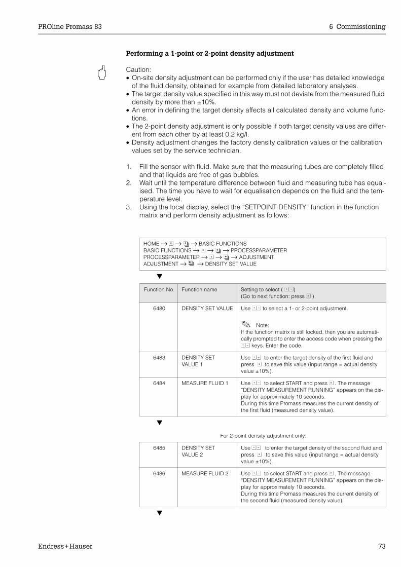
PROline Promass 83 6 Commissioning
Endress+Hauser 73
Performing a 1-point or 2-point density adjustment
" Caution:• On-site density adjustment can be performed only if the user has detailed knowledge
of the fluid density, obtained for example from detailed laboratory analyses.• The target density value specified in this way must not deviate from the measured fluid
density by more than ±10%.• An error in defining the target density affects all calculated density and volume func-
tions.• The 2-point density adjustment is only possible if both target density values are differ-
ent from each other by at least 0.2 kg/l.• Density adjustment changes the factory density calibration values or the calibration
values set by the service technician.
1. Fill the sensor with fluid. Make sure that the measuring tubes are completely filled and that liquids are free of gas bubbles.
2. Wait until the temperature difference between fluid and measuring tube has equal-ised. The time you have to wait for equalisation depends on the fluid and the tem-perature level.
3. Using the local display, select the “SETPOINT DENSITY” function in the function matrix and perform density adjustment as follows:
HOME → F → R → BASIC FUNCTIONSBASIC FUNCTIONS → F → R → PROCESSPARAMETERPROCESSPARAMETER → F → R → ADJUSTMENTADJUSTMENT → N → DENSITY SET VALUE
Function No. Function name Setting to select ( OS)(Go to next function: press F )
6480 DENSITY SET VALUE Use OS to select a 1- or 2-point adjustment.
! Note:If the function matrix is still locked, then you are automati-cally prompted to enter the access code when pressing the OS keys. Enter the code.
6483 DENSITY SET VALUE 1
Use OS to enter the target density of the first fluid and press F to save this value (input range = actual density value ±10%).
6484 MEASURE FLUID 1 Use OS to select START and press F . The message “DENSITY MEASUREMENT RUNNING” appears on the dis-play for approximately 10 seconds.During this time Promass measures the current density of the first fluid (measured density value).
For 2-point density adjustment only:
6485 DENSITY SET VALUE 2
Use OS to enter the target density of the second fluid and press F to save this value (input range = actual density value ±10%).
6486 MEASURE FLUID 2 Use OS to select START and press F . The message “DENSITY MEASUREMENT RUNNING” appears on the dis-play for approximately 10 seconds.During this time Promass measures the current density of the second fluid (measured density value).

6 Commissioning PROline Promass 83
74 Endress+Hauser
6487 DENSITY ADJUSTMENT
Use OS to select DENSITY ADJUSTMENT and press F .Promass compares the measured density value and the target density value and calculates the new density coeffi-cient.
6488 RESTORE ORIGINAL If the density adjustment does not complete correctly, you can select the RESTORE ORIGINAL function to reactivate the default density coefficient.
Back to the HOME position:→ Press and hold down Esc key (X) for longer than three seconds.→ Repeatedly press and release Esc key (X) → exit the function matrix step by step
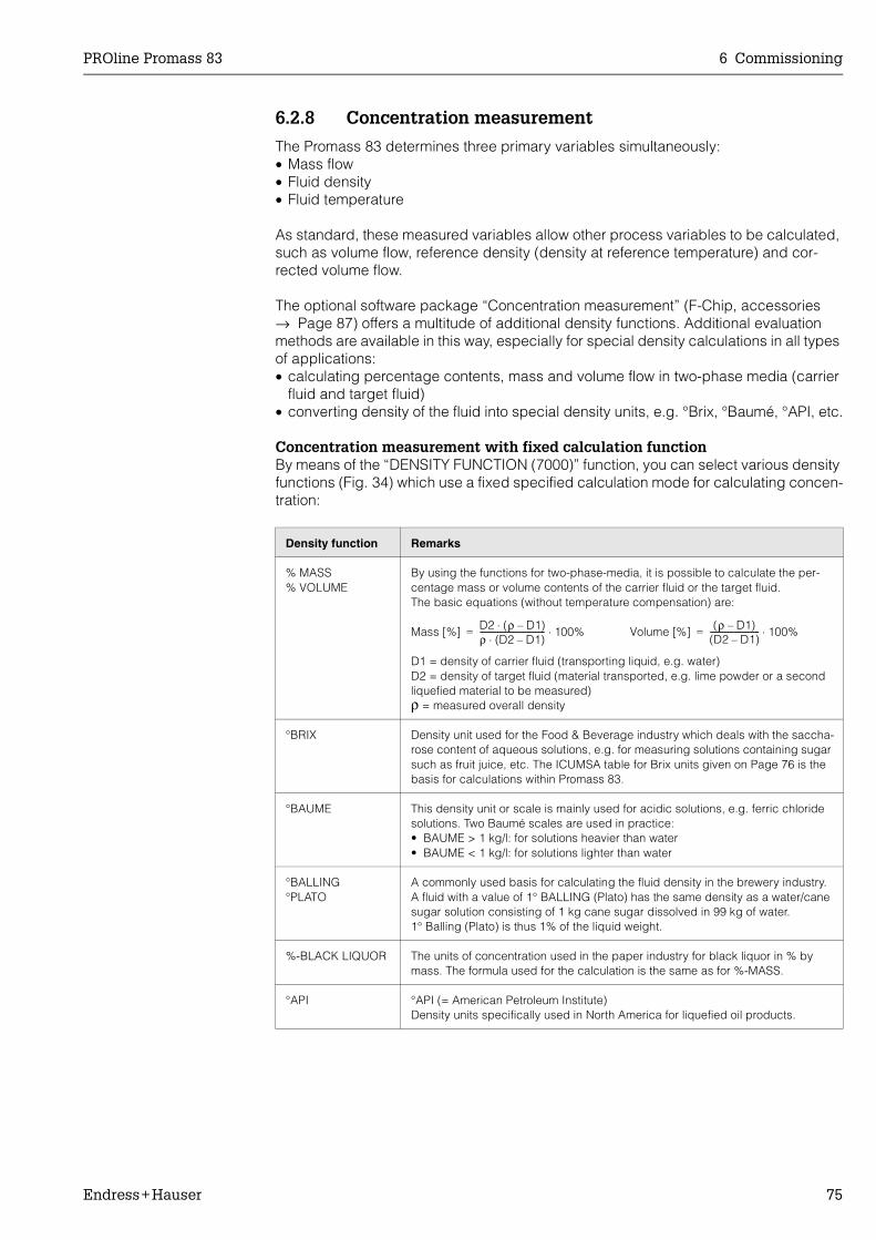
PROline Promass 83 6 Commissioning
Endress+Hauser 75
6.2.8 Concentration measurement
The Promass 83 determines three primary variables simultaneously:• Mass flow• Fluid density• Fluid temperature
As standard, these measured variables allow other process variables to be calculated, such as volume flow, reference density (density at reference temperature) and cor-rected volume flow.
The optional software package “Concentration measurement” (F-Chip, accessories → Page 87) offers a multitude of additional density functions. Additional evaluation methods are available in this way, especially for special density calculations in all types of applications:• calculating percentage contents, mass and volume flow in two-phase media (carrier
fluid and target fluid)• converting density of the fluid into special density units, e.g. °Brix, °Baumé, °API, etc.
Concentration measurement with fixed calculation functionBy means of the “DENSITY FUNCTION (7000)” function, you can select various density functions (Fig. 34) which use a fixed specified calculation mode for calculating concen-tration:
Density function Remarks
% MASS% VOLUME
By using the functions for two-phase-media, it is possible to calculate the per-centage mass or volume contents of the carrier fluid or the target fluid. The basic equations (without temperature compensation) are:
D1 = density of carrier fluid (transporting liquid, e.g. water)D2 = density of target fluid (material transported, e.g. lime powder or a second liquefied material to be measured)ρ = measured overall density
°BRIX Density unit used for the Food & Beverage industry which deals with the saccha-rose content of aqueous solutions, e.g. for measuring solutions containing sugar such as fruit juice, etc. The ICUMSA table for Brix units given on Page 76 is the basis for calculations within Promass 83.
°BAUME This density unit or scale is mainly used for acidic solutions, e.g. ferric chloride solutions. Two Baumé scales are used in practice:• BAUME > 1 kg/l: for solutions heavier than water• BAUME < 1 kg/l: for solutions lighter than water
°BALLING°PLATO
A commonly used basis for calculating the fluid density in the brewery industry. A fluid with a value of 1° BALLING (Plato) has the same density as a water/cane sugar solution consisting of 1 kg cane sugar dissolved in 99 kg of water. 1° Balling (Plato) is thus 1% of the liquid weight.
%-BLACK LIQUOR The units of concentration used in the paper industry for black liquor in % by mass. The formula used for the calculation is the same as for %-MASS.
°API °API (= American Petroleum Institute)Density units specifically used in North America for liquefied oil products.
Mass [%] D2 (ρ D1)–⋅ρ (D2 D1)–⋅--------------------------------- 100%⋅= Volume [%] (ρ D1)–
(D2 D1)–------------------------- 100%⋅=
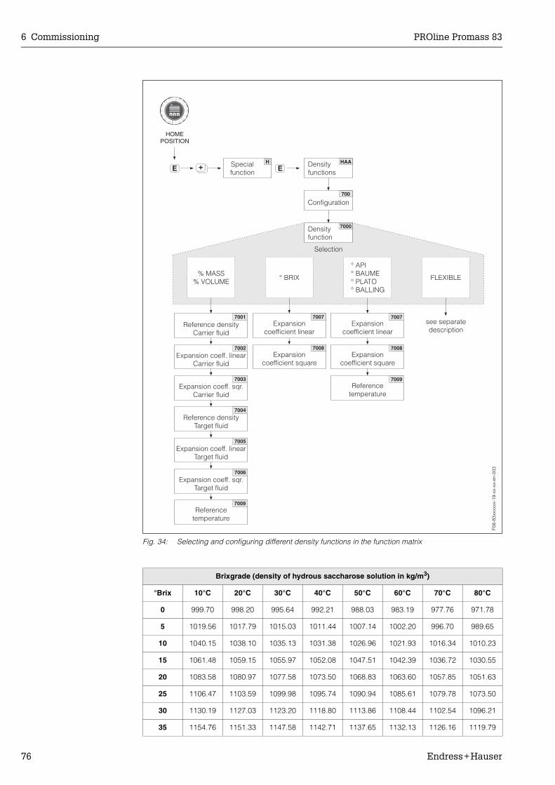
6 Commissioning PROline Promass 83
76 Endress+Hauser
Fig. 34: Selecting and configuring different density functions in the function matrix
Brixgrade (density of hydrous saccharose solution in kg/m3)
°Brix 10°C 20°C 30°C 40°C 50°C 60°C 70°C 80°C
0 999.70 998.20 995.64 992.21 988.03 983.19 977.76 971.78
5 1019.56 1017.79 1015.03 1011.44 1007.14 1002.20 996.70 989.65
10 1040.15 1038.10 1035.13 1031.38 1026.96 1021.93 1016.34 1010.23
15 1061.48 1059.15 1055.97 1052.08 1047.51 1042.39 1036.72 1030.55
20 1083.58 1080.97 1077.58 1073.50 1068.83 1063.60 1057.85 1051.63
25 1106.47 1103.59 1099.98 1095.74 1090.94 1085.61 1079.78 1073.50
30 1130.19 1127.03 1123.20 1118.80 1113.86 1108.44 1102.54 1096.21
35 1154.76 1151.33 1147.58 1142.71 1137.65 1132.13 1126.16 1119.79
++E E
- +
ENDRESS+HAUSER
E
ESC
H
700
HAA
7000
7001
7002
7003
7004
7005
7006
7009
7007
7008
7007
7008
7009
Density
functions
Special
function
Configuration
Density
function
Selection
HOMEPOSITION
Reference density
Carrier fluid
Expansion coeff. linear
Carrier fluid
Expansion coeff. sqr.
Carrier fluid
Reference density
Target fluid
Expansion coeff. linear
Target fluid
Expansion coeff. sqr.
Target fluid
Reference
temperature
% MASS
% VOLUME° BRIX
° API
° BAUME
° PLATO
° BALLING
see separate
description
FLEXIBLE
Expansion
coefficient linear
Expansion
coefficient square
Expansion
coefficient linear
Expansion
coefficient square
Reference
temperature
F06-
83xx
xxxx
-19-
xx-x
x-en
-003
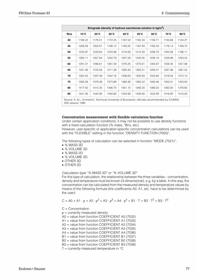
PROline Promass 83 6 Commissioning
Endress+Hauser 77
Concentration measurement with flexible calculation functionUnder certain application conditions, it may not be possible to use density functions with a fixed calculation function (% mass, °Brix, etc).However, user-specific or application-specific concentration calculations can be used with the “FLEXIBLE” setting in the function “DENSITY FUNCTION (7000)”.
The following types of calculation can be selected in function “MODE (7021)”:• % MASS 3D• % VOLUME 3D• % MASS 2D• % VOLUME 2D• OTHER 3D• OTHER 2D
Calculation type “% MASS 3D” or “% VOLUME 3D”For this type of calculation, the relationship between the three variables – concentration, density and temperature must be known (3-dimensional), e.g. by a table. In this way, the concentration can be calculated from the measured density and temperature values by means of the following formula (the coefficients A0, A1, etc. have to be determined by the user):
C = A0 + A1 · ρ + A2 · ρ2 + A3 · ρ3 + A4 · ρ4 + B1 · T + B2 · T2 + B3 · T3
C = Concentrationρ = currently measured densityA0 = value from function COEFFICIENT A0 (7032)A1 = value from function COEFFICIENT A1 (7033)A2 = value from function COEFFICIENT A2 (7034)A3 = value from function COEFFICIENT A3 (7035)A4 = value from function COEFFICIENT A4 (7036)B1 = value from function COEFFICIENT B1 (7037)B2 = value from function COEFFICIENT B2 (7038)B3 = value from function COEFFICIENT B3 (7039)T = currently measured temperature in °C
40 1180.22 1176.51 1172.25 1167.52 1162.33 1156.71 1150.68 1144.27
45 1206.58 1202.61 1198.15 1193.25 1187.94 1182.23 1176.14 1169.70
50 1233.87 1229.64 1224.98 1219.93 1214.50 1208.70 1202.56 1196.11
55 1262.11 1257.64 1252.79 1247.59 1242.05 1236.18 1229.98 1223.53
60 1291.31 1286.61 1281.59 1276.25 1270.61 1264.67 1258.45 1251.88
65 1321.46 1316.56 1311.38 1305.93 1300.21 1294.21 1287.96 1281.52
70 1352.55 1347.49 1342.18 1336.63 1330.84 1324.80 1318.55 1312.13
75 1384.58 1379.38 1373.88 1368.36 1362.52 1356.46 1350.21 1343.83
80 1417.50 1412.20 1406.70 1401.10 1395.20 1389.20 1383.00 1376.60
85 1451.30 1445.90 1440.80 1434.80 1429.00 1422.90 1416.80 1410.50
Source: A. & L. Emmerich, Technical University of Brunswick; officially recommended by ICUMSA, 20th session 1990
Brixgrade (density of hydrous saccharose solution in kg/m3)
°Brix 10°C 20°C 30°C 40°C 50°C 60°C 70°C 80°C
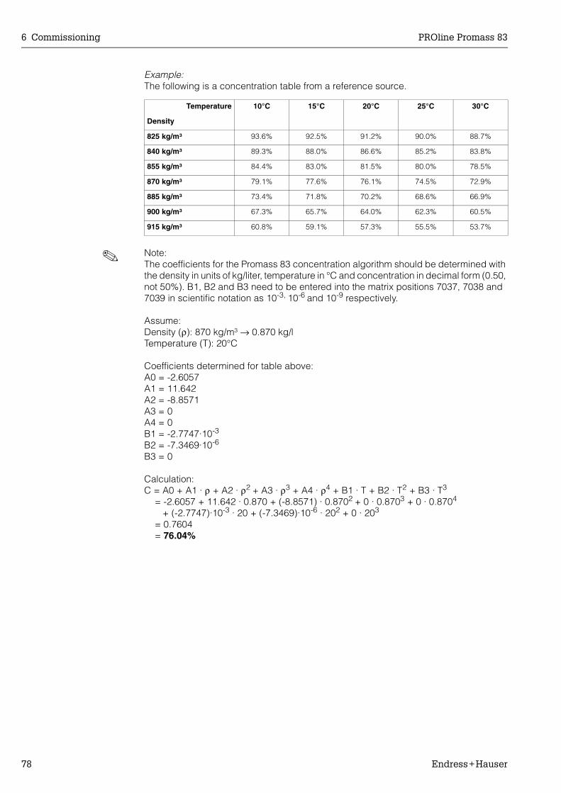
6 Commissioning PROline Promass 83
78 Endress+Hauser
Example:The following is a concentration table from a reference source.
! Note:The coefficients for the Promass 83 concentration algorithm should be determined with the density in units of kg/liter, temperature in °C and concentration in decimal form (0.50, not 50%). B1, B2 and B3 need to be entered into the matrix positions 7037, 7038 and 7039 in scientific notation as 10-3, 10-6 and 10-9 respectively.
Assume:Density (ρ): 870 kg/m³ → 0.870 kg/lTemperature (T): 20°C
Coefficients determined for table above:A0 = -2.6057A1 = 11.642A2 = -8.8571A3 = 0A4 = 0B1 = -2.7747·10-3
B2 = -7.3469·10-6
B3 = 0
Calculation:C = A0 + A1 · ρ + A2 · ρ2 + A3 · ρ3 + A4 · ρ4 + B1 · T + B2 · T2 + B3 · T3
= -2.6057 + 11.642 · 0.870 + (-8.8571) · 0.8702 + 0 · 0.8703 + 0 · 0.8704
+ (-2.7747)·10-3 · 20 + (-7.3469)·10-6 · 202 + 0 · 203
= 0.7604= 76.04%
Temperature 10°C 15°C 20°C 25°C 30°C
Density
825 kg/m³ 93.6% 92.5% 91.2% 90.0% 88.7%
840 kg/m³ 89.3% 88.0% 86.6% 85.2% 83.8%
855 kg/m³ 84.4% 83.0% 81.5% 80.0% 78.5%
870 kg/m³ 79.1% 77.6% 76.1% 74.5% 72.9%
885 kg/m³ 73.4% 71.8% 70.2% 68.6% 66.9%
900 kg/m³ 67.3% 65.7% 64.0% 62.3% 60.5%
915 kg/m³ 60.8% 59.1% 57.3% 55.5% 53.7%
PROline Promass 83 6 Commissioning
Endress+Hauser 79
Calculation type “% MASS 2D” or “% VOLUME 2D”For this type of calculation, the relationship between the two variables concentration and reference density must be known (2-dimensional), e.g. by a table. In this way, the concentration can be calculated from the measured reference density by means of the following formula (the coefficients A0, A1, etc. have to be determined either by the user or by the FieldTool program):
C = A0 + A1 · ρref + A2 · ρref2 + A3 · ρref
3 + A4 · ρref4
C = Concentrationρref = currently measured reference densityA0 = value from function COEFFICIENT A0 (7032)A1 = value from function COEFFICIENT A1 (7033)A2 = value from function COEFFICIENT A2 (7034)A3 = value from function COEFFICIENT A3 (7035)A4 = value from function COEFFICIENT A4 (7036)
! Note!Promass determines the reference density by means of the density and temperature currently measured. To do so, both the reference temperature (function REFERENCE TEMPERATURE) and the expansion coefficients (function EXPANSION COEFF. .....) must be entered in the measuring system.The parameters important for measuring the reference density can also be configured directly via the “Commissioning” Quick Setup menu.
Calculation type “OTHER 3D” or “OTHER 2D”With this option, users can enter a free selectable designation for their specific concen-tration unit or target parameters (see function TEXT ARBITRARY CONCENTRATION (0606)).

6 Commissioning PROline Promass 83
80 Endress+Hauser
6.2.9 Advanced diagnostic functions
Changes to the measuring system, e.g. coating build-up or corrosion and abrasion on the measuring tubes can be detected at an early stage by means of the optional soft-ware package “Advanced Diagnostics” (F-Chip, accessories → Page 87). Normally, these influences reduce the measuring accuracy of the system or may lead to serious system errors.By means of the diagnostic functions it is now possible to record various process and device parameters during operation, e.g. mass flow, density/reference density, temper-ature values, measuring tube damping etc. By analysing the trend of these measured values, deviations of the measuring system from a “reference status” can be detected in good time and corrective measures can be taken.
Reference values as the basis for trend analysisReference values of the parameters in question must always be recorded for trend analysis. These reference values are determined under reproducible, constant condi-tions. Such reference values are initially recorded during calibration at the factory and saved in the measuring device.Reference data can also be ascertained under customer-specific process conditions, e.g. during commissioning or at certain process stages (cleaning cycles, etc.).Reference values are recorded and saved in the measuring system always by means of the device function → REFERENCE CONDITION USER (7401).
" Caution!It is not possible to analyse the trend of process/device parameters without reference values! Reference values can only be determined under constant, non-changing proc-ess conditions.
Methods of ascertaining dataProcess and device parameters can be recorded in two different ways which you can define in the function → ACQUISITION MODE (7410):• “PERIODICAL” option: Measuring device acquires data periodically. Enter the desired
time interval by means of the function “ACQUISITION PERIODE (7411)”.• “SINGLE SHOT” option: The user himself acquires the data manually at different, free
selectable periods.
Ensure that the process conditions always correspond to the reference status when data is being recorded. It is only in this way that deviations from the reference status can be clearly determined.
! Note!The last ten entries are retained in chronological order in the measuring system.The “history” of such values can be called up via various functions:
Diagnosis parameters
Data saved (per parameter)
Mass flowDensityReference densityTemperatureMeas. tube dampingSensor symmetry
• Reference value → “REFERENCE VALUE” function• Lowest measured value → “MINIMUM VALUE” function• Highest measured value → “MAXIMUM VALUE” function• List of the last ten measured values → “HISTORY 1” function• Deviation measured/reference value → “ACTUAL DEVIATION” function
! Note:More detailed information can be found in the “Description of Device Functions” Manual.
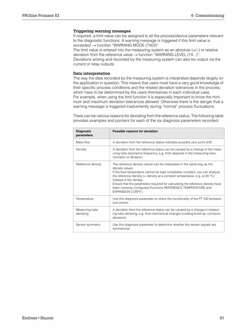
PROline Promass 83 6 Commissioning
Endress+Hauser 81
Triggering warning messagesIf required, a limit value can be assigned to all the process/device parameters relevant to the diagnostic functions. A warning message is triggered if this limit value is exceeded → function “WARNING MODE (7403)”.The limit value is entered into the measuring system as an absolute (+/–) or relative deviation from the reference value → function “WARNING LEVEL (74...)”. Deviations arising and recorded by the measuring system can also be output via the current or relay outputs.
Data interpretationThe way the data recorded by the measuring system is interpreted depends largely on the application in question. This means that users must have a very good knowledge of their specific process conditions and the related deviation tolerances in the process, which have to be determined by the users themselves in each individual case. For example, when using the limit function it is especially important to know the mini-mum and maximum deviation tolerances allowed. Otherwise there is the danger that a warning message is triggered inadvertently during “normal” process fluctuations.
There can be various reasons for deviating from the reference status. The following table provides examples and pointers for each of the six diagnosis parameters recorded:
Diagnosis parameters
Possible reasons for deviation
Mass flow A deviation from the reference status indicates possible zero point shift.
Density A deviation from the reference status can be caused by a change in the meas-uring tube resonance frequency, e.g. from deposits in the measuring tube, corrosion or abrasion.
Reference density The reference density values can be interpreted in the same way as the density values. If the fluid temperature cannot be kept completely constant, you can analyse the reference density (= density at a constant temperature, e.g. at 20 °C) instead of the density.Ensure that the parameters required for calculating the reference density have been correctly configured (functions REFERENCE TEMPERATURE and EXPANSION COEFF.).
Temperature Use this diagnosis parameter to check the functionality of the PT 100 tempera-ture sensor.
Measuring tube damping
A deviation from the reference status can be caused by a change in measur-ing tube damping, e.g. from mechanical changes (coating build-up, corrosion, abrasion).
Sensor symmetry Use this diagnosis parameter to determine whether the sensor signals are symmetrical.
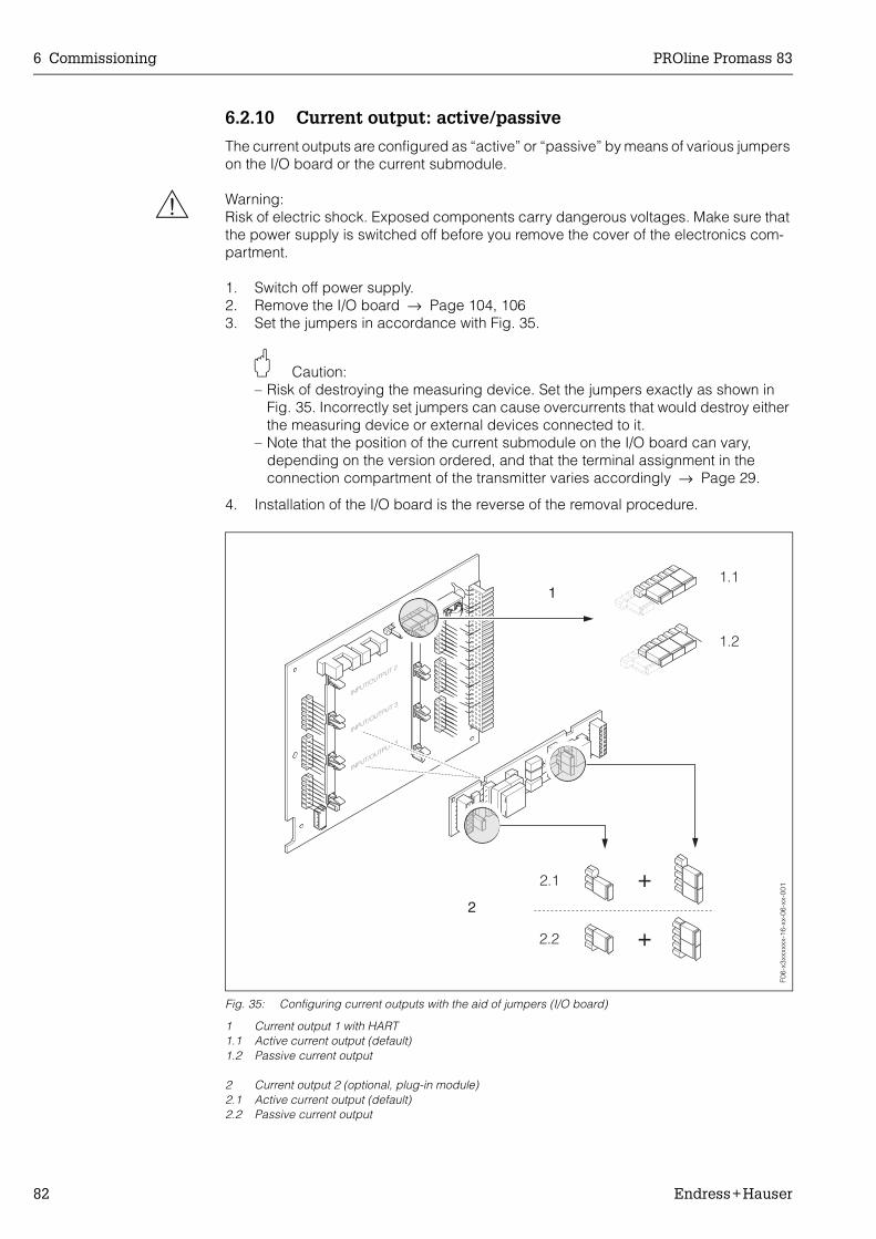
6 Commissioning PROline Promass 83
82 Endress+Hauser
6.2.10 Current output: active/passive
The current outputs are configured as “active” or “passive” by means of various jumpers on the I/O board or the current submodule.
# Warning:Risk of electric shock. Exposed components carry dangerous voltages. Make sure that the power supply is switched off before you remove the cover of the electronics com-partment.
1. Switch off power supply.2. Remove the I/O board → Page 104, 1063. Set the jumpers in accordance with Fig. 35.
" Caution:– Risk of destroying the measuring device. Set the jumpers exactly as shown in
Fig. 35. Incorrectly set jumpers can cause overcurrents that would destroy either the measuring device or external devices connected to it.
– Note that the position of the current submodule on the I/O board can vary, depending on the version ordered, and that the terminal assignment in the connection compartment of the transmitter varies accordingly → Page 29.
4. Installation of the I/O board is the reverse of the removal procedure.
Fig. 35: Configuring current outputs with the aid of jumpers (I/O board)
1 Current output 1 with HART1.1 Active current output (default)1.2 Passive current output
2 Current output 2 (optional, plug-in module)2.1 Active current output (default)2.2 Passive current output
F06-
x3xx
xxxx
-16-
xx-0
6-xx
-001
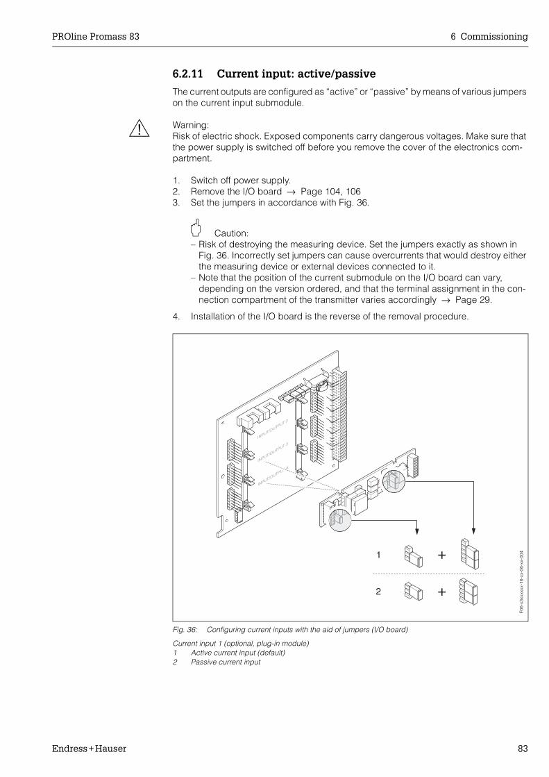
PROline Promass 83 6 Commissioning
Endress+Hauser 83
6.2.11 Current input: active/passive
The current outputs are configured as “active” or “passive” by means of various jumpers on the current input submodule.
# Warning:Risk of electric shock. Exposed components carry dangerous voltages. Make sure that the power supply is switched off before you remove the cover of the electronics com-partment.
1. Switch off power supply.2. Remove the I/O board → Page 104, 1063. Set the jumpers in accordance with Fig. 36.
" Caution:– Risk of destroying the measuring device. Set the jumpers exactly as shown in
Fig. 36. Incorrectly set jumpers can cause overcurrents that would destroy either the measuring device or external devices connected to it.
– Note that the position of the current submodule on the I/O board can vary, depending on the version ordered, and that the terminal assignment in the con-nection compartment of the transmitter varies accordingly → Page 29.
4. Installation of the I/O board is the reverse of the removal procedure.
Fig. 36: Configuring current inputs with the aid of jumpers (I/O board)
Current input 1 (optional, plug-in module)1 Active current input (default)2 Passive current input
INPUT/OUTPUT 4
1
2 +
+
INPUT/OUTPUT 3
INPUT/OUTPUT 2
F06-
x3xx
xxxx
-16-
xx-0
6-xx
-004

6 Commissioning PROline Promass 83
84 Endress+Hauser
6.2.12 Relay contacts: Normally closed/Normally open
The relay contact can be configured as normally open (NO or make) or normally closed (NC or break) contacts by means of two jumpers on the I/O board or on the pluggable submodule. This configuration can be called up at any time with the “ACTUAL STATUS RELAY” function (No. 4740).
# Warning:Risk of electric shock. Exposed components carry dangerous voltages. Make sure that the power supply is switched off before you remove the cover of the electronics com-partment.
1. Switch off power supply.2. Remove the I/O board → Page 104, 1063. Set the jumpers in accordance with Fig. 37.
" Caution:– If you change the setting you must always change the positions of both jumpers.
Note precisely the specified positions of the jumpers.– Note that the position of the relay submodule on the I/O board can vary, depend-
ing on the version ordered, and that the terminal assignment in the connection compartment of the transmitter varies accordingly → see Page 29.
4. Installation of the I/O board is the reverse of the removal procedure.
Fig. 37: Configuring relay contacts (NC / NO) on the convertible I/O board (submodule).
1 Configured as NO contact (default, relay 1)2 Configured as NC contact (default, relay 2, if installed)
Fig. 38: Configuring relay contacts (NC / NO) on the non-convertible I/O board.A = relay 1; B = relay 2
1 Configured as NO contact (default, relay 1)2 Configured as NC contact (default, relay 2)
INPUT/OUTPUT 4
INPUT/OUTPUT 3
+
+1
2
INPUT/OUTPUT 2
F06-
x3xx
xxxx
-16-
xx-0
6-xx
-002
+
+
1
2
+
+
1
A
B
2
F06-
x3xx
xxxx
-16-
xx-0
6-xx
-003

PROline Promass 83 6 Commissioning
Endress+Hauser 85
6.3 Purge and pressure monitoring connections
The sensor housing protects the inner electronics and mechanics and is filled with dry nitrogen. Beyond that, up to a specified measuring pressure it additionally serves as secondary containment.
# Warning:For a process pressure above the specified containment pressure, the housing does not serve as an additional secondary containment. In case a danger of measuring tube fail-ure exists due to process characteristics, e.g. with corrosive process fluids, we recom-mend the use of sensors whose housing is equipped with special pressure monitoring connections (ordering option). With the help of these connections, fluid collected in the housing in the event of tube failure can be drained off. This diminishes the danger of mechanical overload of the housing, which could lead to a housing failure and accord-ingly is connected with an increased danger potential. These connections can also be used for gas purging (gas detection).
The following instructions apply to handling sensors with purge or pressure monitoring connections:• Do not open the purge connections unless the containment can be filled immediately
with a dry inert gas.• Use only low gauge pressure to purge. Maximum pressure 5 bar.
6.4 Data storage device (DAT, F-Chip)
S-DAT (Sensor-DAT)The S-DAT is an exchangeable data storage device in which all sensor relevant para-meters are stored, i.e., diameter, serial number, calibration factor, zero point.
T-DAT (Transmitter-DAT)The T-DAT is an exchangeable data storage device in which all transmitter parameters and settings are stored.Storing of specific parameter settings from the EEPROM to the T-DAT and vice versa has to be carried out by the user (= manual save function). Detailed instructions regarding this can be found in the handbook “Description of Device Functions” (function “T-DAT SAVE/LOAD”, No. 1009).
F-Chip (Function-Chip)The F-Chip is a microprocessor chip that contains additional software packages that extend the functionality and application possibilities of the transmitter.In the case of a later upgrade, the F-Chip can be ordered as an accessory (see Page 87) and can simply be plugged on to the I/O board (see Page 103). After start up, the software is immediately made available to the transmitter.
" Caution:To ensure an unambiguous assignment, the F-Chip is coded with the transmitter serial number once it is plugged in. Thus, it can not be reused with other measuring devices.
7 Maintenance PROline Promass 83
86 Endress+Hauser
7 Maintenance
The Promass 83 flow measuring system requires no special maintenance.
Exterior cleaningWhen cleaning the exterior of measuring devices, always use cleaning agents that do not attack the surface of the housing and the seals.
Cleaning with pigs (Promass H, I)If pigs are used for cleaning, it is essential to take the inside diameters of measuring tube and process connection into account (see Page 177 ff.).
Replacing sealsUnder normal circumstances, fluid wetted seals of the Promass A and Promass M sensors do not require replacement. Replacement is necessary only in special circumstances, for example if aggressive or corrosive fluids are incompatible with the seal material.
! Note:• The period between changes depends on the fluid properties and on the frequency
of cleaning cycles in the case of CIP/SIP cleaning.• Replacement seals (accessories) → Page 87.

PROline Promass 83 8 Accessories
Endress+Hauser 87
8 Accessories
Various accessories, which can be ordered separately from Endress+Hauser, are avail-able for the transmitter and the sensor. The E+H service organisation can provide detailed information on the order codes of your choice.
Accessory Description Ordering code
TransmitterPROline Promass 83
Transmitter for replacement or for stock. Use the order code to define the following specifi-cations:– Approvals– Degree of protection / version– Cable entries– Display / power supply / operation– Software– Outputs / inputs
83XXX − XXXXX * * * * * *
Inputs/outputs Conversion kit with appropriate plug-in point modules for converting the input/output con-figuration in place to date to a new version.
DK8UI − * * * *
Software packages forPromass 83
Software add-ons on F-Chip, can be ordered individually:– Extended diagnosis– Batching functions– Concentration measurement
DK8SO – *
Installation set for transmitter
Mounting set for remote version. Suitable for:– Wall mounting– Pipe mounting– Installation in control panel
DK8WM − *
Post mounting set for the Promass A sensor
Post mounting set for the Promass A DK8AS − * *
Mounting set for the Promass A sensor
Mounting set for Promass A, comprising:– 2 process connections (see Page 169 ff.)– Seals
DK8MS − * * * * * *
Set of seals for sensor For regular replacement of the seals of the Promass M and Promass A sensors.Set consists of two seals.
DKS − * * *
HART Communicator DXR 375 handheld terminal
Handheld terminal for remote parameterisa-tion and for obtaining measured values via the current output HART (4...20 mA).
Contact your E+H representative for more information.
DXR375 − * * * * * *
Applicator Software for selecting and configuring flow-meters.Applicator can be downloaded from the Inter-net or ordered on CD-ROM for installation on a local PC.
Contact your E+H representative for more information.
DKA80 − *
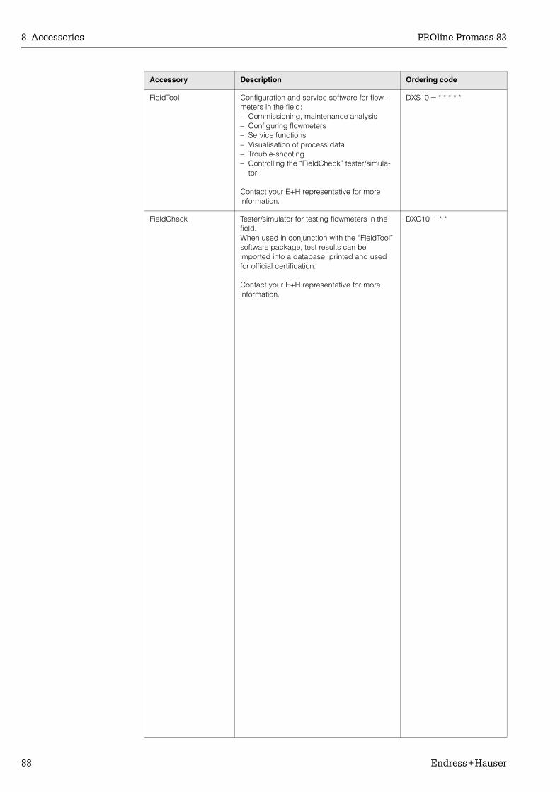
8 Accessories PROline Promass 83
88 Endress+Hauser
FieldTool Configuration and service software for flow-meters in the field:– Commissioning, maintenance analysis– Configuring flowmeters– Service functions– Visualisation of process data– Trouble-shooting– Controlling the “FieldCheck” tester/simula-
tor
Contact your E+H representative for more information.
DXS10 − * * * * *
FieldCheck Tester/simulator for testing flowmeters in the field. When used in conjunction with the “FieldTool” software package, test results can be imported into a database, printed and used for official certification.
Contact your E+H representative for more information.
DXC10 − * *
Accessory Description Ordering code

PROline Promass 83 9 Trouble-shooting
Endress+Hauser 89
9 Trouble-shooting
9.1 Trouble-shooting instructions
Always start trouble-shooting with the checklists below, if faults occur after start-up or during operation. The routine takes you directly to the cause of the problem and the appropriate remedial measures.
Check the display
No display visible and no output signals present.
1. Check the power supply → Terminals 1, 22. Check the power line fuse → Page 108
85...260 V AC: 0.8 A slow-blow / 250 V20...55 V AC and 16...62 V DC: 2 A slow-blow / 250 V
3. Measuring electronics defective → order spare parts → Page 103
No display visible, but out-put signals are present.
1. Check whether the ribbon-cable connector of the display module is correctly plugged into the amplifier board → Page 105, 107
2. Display module defective → order spare parts → Page 1033. Measuring electronics defective → order spare parts → Page 103
Display texts are in a foreign language.
Switch off power supply. Press and hold down both the OS keys and switch on the measuring device. The display text will appear in English (default) and is displayed at maximum contrast.
Measured value indicated, but no signal at the current or pulse output
Measuring electronics defective → order spare parts → Page 103
Error messages on display
Errors which occur during commissioning or measuring operation are displayed immediately.Error messages consist of a variety of icons. The meanings of these icons are as follows (example):
– Error type: S = system error, P = process error– Error message type: $ = fault message, ! = notice message– MEDIUM INHOM. = error designation, e.g. fluid is not homogeneous– 03:00:05 = duration of error occurrence (in hours, minutes and seconds)– # 702 = error number
" Caution:• See the information on Page 42 ff.!• The measuring system interprets simulations and positive zero return as system errors, but displays
them as notice message only.
Error number:No. 001 – 399No. 501 – 699
System error (device error) has occurred → Page 90
Error number:No. 400 – 499No. 700 – 799
Process error (application error) has occurred → Page 98
Other error (without error message)
Some other error has occurred.
Diagnosis and rectification → Page 100

9 Trouble-shooting PROline Promass 83
90 Endress+Hauser
9.2 System error messages
Serious system errors are always recognised by the instrument as “Fault message”, and are shown as a lightning flash ($) on the display. Fault messages immediately affect the inputs and outputs. Simulations and positive zero return, on the other hand, are classed and displayed as “Notice messages”.
" Caution:In the event of a serious fault, a flowmeter might have to be returned to the manufacturer for repair. The procedures on Page 8 must be carried out before you return a flowmeter to Endress+Hauser.Always enclose a duly completed “Declaration of contamination” form. You will find a preprinted blank of the this form at the back of this manual.
! Note:• The listed error message types below correspond to the factory setting.• Also observe the information on Page 42 ff. and 101.
Type Error message / No. Cause Remedy / spare part
S = System error$ = Fault message (with an effect on the outputs)! = Notice message (without an effect on the outputs)
No. # 0xx → Hardware error
S$
CRITICAL FAILURE# 001
Serious device error Replace the amplifier board. Spare parts → Page 103
S$
AMP HW EEPROM# 011
Amplifier:Defective EEPROM
Replace the amplifier board. Spare parts → Page 103
S$
AMP SW EEPROM# 012
Amplifier:Error accessing EEPROM data
The EEPROM data blocks in which an error has occurred are displayed in the “TROUBLE-SHOOTING” function.Press Enter to acknowledge the errors in question; default values are automatically inserted instead of the errored parameter values.
! Note:The measuring device has to be restarted if an error has occurred in a totalizer block (see error No. 111 / CHECKSUM TOTAL.).
S$
SENSOR HW DAT# 031
Sensor DAT:1. S-DAT is defective.2. S-DAT is not plugged into the
amplifier board or is missing.
1. Replace the S-DAT.Spare parts → Page 103Check the spare part set number to ensure that the new, replacement DAT is compati-ble with the measuring elec-tronics.
2. Plug the S-DAT into the amplifier board → Page 105, 107
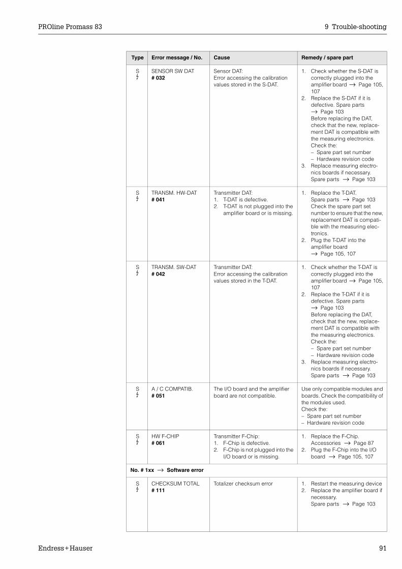
PROline Promass 83 9 Trouble-shooting
Endress+Hauser 91
S$
SENSOR SW DAT# 032
Sensor DAT:Error accessing the calibration values stored in the S-DAT.
1. Check whether the S-DAT is correctly plugged into the amplifier board → Page 105, 107
2. Replace the S-DAT if it is defective. Spare parts → Page 103Before replacing the DAT, check that the new, replace-ment DAT is compatible with the measuring electronics. Check the:– Spare part set number– Hardware revision code
3. Replace measuring electro-nics boards if necessary.Spare parts → Page 103
S$
TRANSM. HW-DAT# 041
Transmitter DAT:1. T-DAT is defective.2. T-DAT is not plugged into the
amplifier board or is missing.
1. Replace the T-DAT.Spare parts → Page 103Check the spare part set number to ensure that the new, replacement DAT is compati-ble with the measuring elec-tronics.
2. Plug the T-DAT into the amplifier board → Page 105, 107
S$
TRANSM. SW-DAT# 042
Transmitter DAT:Error accessing the calibration values stored in the T-DAT.
1. Check whether the T-DAT is correctly plugged into the amplifier board → Page 105, 107
2. Replace the T-DAT if it is defective. Spare parts → Page 103Before replacing the DAT, check that the new, replace-ment DAT is compatible with the measuring electronics. Check the:– Spare part set number– Hardware revision code
3. Replace measuring electro-nics boards if necessary.Spare parts → Page 103
S$
A / C COMPATIB.# 051
The I/O board and the amplifier board are not compatible.
Use only compatible modules and boards. Check the compatibility of the modules used.Check the:– Spare part set number– Hardware revision code
S$
HW F-CHIP# 061
Transmitter F-Chip:1. F-Chip is defective.2. F-Chip is not plugged into the
I/O board or is missing.
1. Replace the F-Chip.Accessories → Page 87
2. Plug the F-Chip into the I/O board → Page 105, 107
No. # 1xx → Software error
S$
CHECKSUM TOTAL# 111
Totalizer checksum error 1. Restart the measuring device2. Replace the amplifier board if
necessary.Spare parts → Page 103
Type Error message / No. Cause Remedy / spare part

9 Trouble-shooting PROline Promass 83
92 Endress+Hauser
S!
A / C COMPATIB.# 121
Due to different software ver-sions, I/O board and amplifier board are only partially compati-ble (possibly restricted function-ality).
! Note:– This message is only listed in
the error history.– Nothing is displayed on the
display.
Module with lower software ver-sion has either to be actualizied by FieldTool with the required soft-ware version or the module has to be replaced.
Spare parts → Page 103
No. # 2xx → Error in DAT / no communication
S!
LOAD T-DAT # 205
Transmitter DAT:Data backup (downloading) to T-DAT failed, or error when accessing (uploading) the cali-bration values stored in the T-DAT™.
1. Check whether the T-DAT is correctly plugged into the amplifier board, → Page 105 107
2. Replace the T-DAT if it is defective. Spare parts → Page 103Before replacing the DAT, check that the new, replace-ment DAT is compatible with the measuring electronics. Check the:– Spare part set number– Hardware revision code
3. Replace measuring electro-nics boards if necessary.Spare parts → Page 103
S!
SAVE T-DAT# 206
S$
COMMUNIC. AMP.# 251
Internal communication fault on the amplifier board.
Remove the amplifier board.Spare parts → Page 103
S$
COMMUNICATION I/O# 261
No data reception between amplifier and I/O board or faulty internal data transfer.
Check the BUS contacts
No. # 3xx → System limits exceeded (internal device error)
S!
STACK CUR OUT n# 339…342
The temporarily buffered flow portions (measuring mode for pulsating flow) could not be cleared or output within 60 seconds.
1. Change the upper or lower limit setting, as applicable.
2. Increase or reduce flow, as applicable.
Recommendations in the event of fault category = FAULT MESSAGE ($):– Configure the fault response of
the output to “ACTUAL VALUE” (see Page 101), so that the tem-porary buffer can be cleared.
– Clear the temporary buffer by the measures described under Item 1.
S!
STACK FREQ. OUT n# 343…346
Type Error message / No. Cause Remedy / spare part
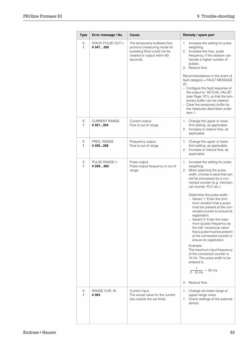
PROline Promass 83 9 Trouble-shooting
Endress+Hauser 93
S!
STACK PULSE OUT n# 347…350
The temporarily buffered flow portions (measuring mode for pulsating flow) could not be cleared or output within 60 seconds.
1. Increase the setting for pulse weighting
2. Increase the max. pulse frequency, if the totalizer can handle a higher number of pulses.
3. Reduce flow
Recommendations in the event of fault category = FAULT MESSAGE ($):– Configure the fault response of
the output to “ACTUAL VALUE” (see Page 101), so that the tem-porary buffer can be cleared.
– Clear the temporary buffer by the measures described under Item 1.
S!
CURRENT RANGE# 351...354
Current output:Flow is out of range.
1. Change the upper or lower limit setting, as applicable.
2. Increase or reduce flow, as applicable.
S!
FREQ. RANGE# 355...358
Frequency output:Flow is out of range.
1. Change the upper or lower limit setting, as applicable.
2. Increase or reduce flow, as applicable.
S!
PULSE RANGE n# 359…362
Pulse output:Pulse output frequency is out of range.
1. Increase the setting for pulse weighting
2. When selecting the pulse width, choose a value that can still be processed by a con-nected counter (e.g. mechani-cal counter, PLC etc.).
Determine the pulse width:– Variant 1: Enter the mini-
mum duration that a pulse must be present at the con-nected counter to ensure its registration.
– Variant 2: Enter the maxi-mum (pulse) frequency as the half “reciprocal value” that a pulse must be present at the connected counter to ensure its registration.
Example:The maximum input frequency of the connected counter is 10 Hz. The pulse width to be entered is:
3. Reduce flow.
S!
RANGE CUR. IN# 363
Current input:The actual value for the current lies outside the set limits.
1. Change set lower-range or upper-range value.
1. Check settings of the external sensor.
Type Error message / No. Cause Remedy / spare part
12 10 Hz⋅----------------------- 50 ms=
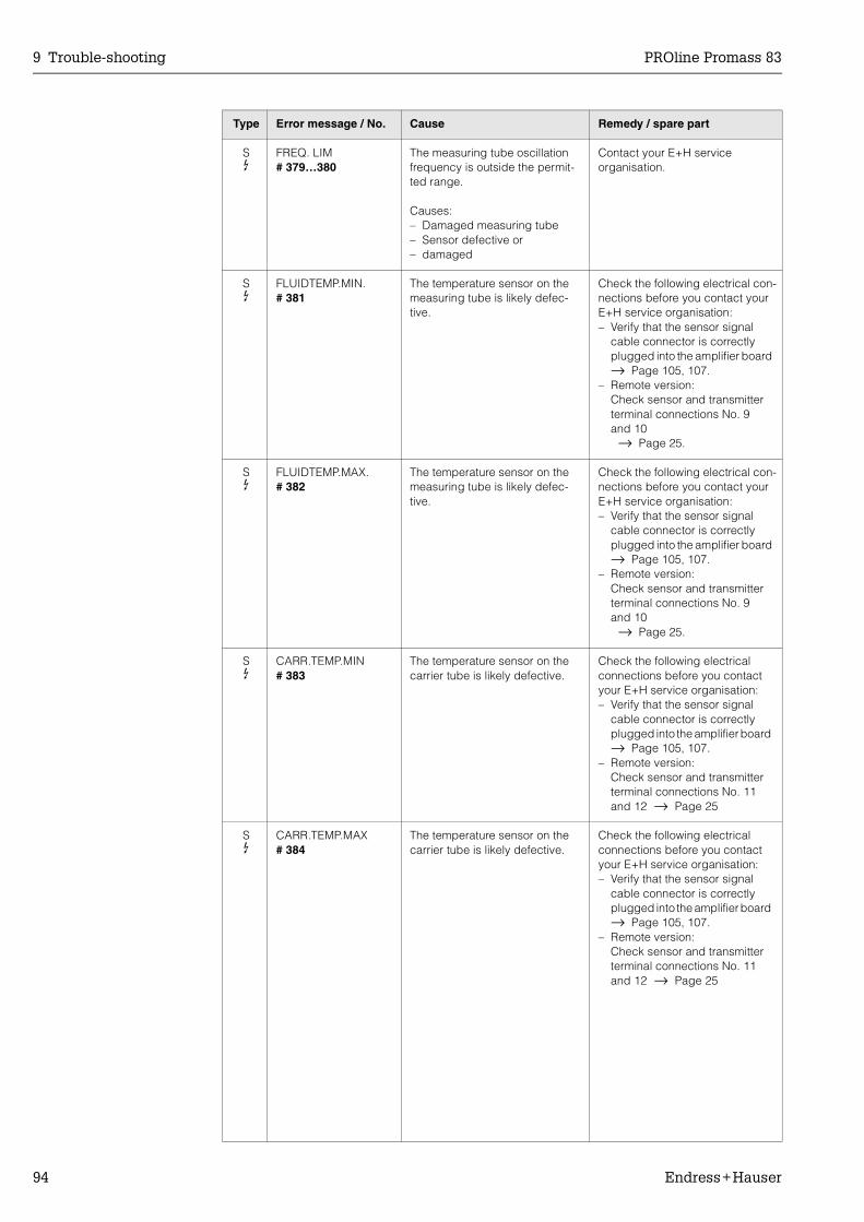
9 Trouble-shooting PROline Promass 83
94 Endress+Hauser
S$
FREQ. LIM# 379…380
The measuring tube oscillation frequency is outside the permit-ted range.
Causes:– Damaged measuring tube– Sensor defective or – damaged
Contact your E+H service organisation.
S$
FLUIDTEMP.MIN.# 381
The temperature sensor on the measuring tube is likely defec-tive.
Check the following electrical con-nections before you contact your E+H service organisation:– Verify that the sensor signal
cable connector is correctly plugged into the amplifier board → Page 105, 107.
– Remote version:Check sensor and transmitter terminal connections No. 9 and 10 → Page 25.
S$
FLUIDTEMP.MAX.# 382
The temperature sensor on the measuring tube is likely defec-tive.
Check the following electrical con-nections before you contact your E+H service organisation:– Verify that the sensor signal
cable connector is correctly plugged into the amplifier board → Page 105, 107.
– Remote version:Check sensor and transmitter terminal connections No. 9 and 10 → Page 25.
S$
CARR.TEMP.MIN# 383
The temperature sensor on the carrier tube is likely defective.
Check the following electrical connections before you contact your E+H service organisation:– Verify that the sensor signal
cable connector is correctly plugged into the amplifier board → Page 105, 107.
– Remote version:Check sensor and transmitter terminal connections No. 11 and 12 → Page 25
S$
CARR.TEMP.MAX# 384
The temperature sensor on the carrier tube is likely defective.
Check the following electrical connections before you contact your E+H service organisation:– Verify that the sensor signal
cable connector is correctly plugged into the amplifier board → Page 105, 107.
– Remote version:Check sensor and transmitter terminal connections No. 11 and 12 → Page 25
Type Error message / No. Cause Remedy / spare part

PROline Promass 83 9 Trouble-shooting
Endress+Hauser 95
S$
INL.SENS.DEF.# 385
One of the measuring tube exciter coils (inlet) is likely defec-tive.
Check the following electrical connections before you contact your E+H service organisation:– Verify that the sensor signal
cable connector is correctly plugged into the amplifier board → Page 105, 107.
– Remote version:Check sensor and transmitter terminal connections No. 4, 5, 6 and 7 → Page 25.
S$
OUTL.SENS.DEF.# 386
One of the measuring tube exciter coils (outlet) is likely defective.
Check the following electrical connections before you contact your E+H service organisation:– Verify that the sensor signal
cable connector is correctly plugged into the amplifier board → Page 105, 107.
– Remote version:Check sensor and transmitter terminal connections No. 4, 5, 6 and 7 → Page 25.
S$
SEN.ASY.EXCEED# 387
Measuring pipe excitation coil is probably faulty.
Check the following electrical connections before you contact your E+H service organisation:– Verify that the sensor signal
cable connector is correctly plugged into the amplifier board → Page 105, 107.
– Remote version:Check sensor and transmitter terminal connections No. 4, 5, 6 and 7 → Page 25.
S$
AMP. FAULT# 388 / 389 / 390
Amplifier error Contact your E+H service organisation.
No. # 5xx → Application error
S!
SW.-UPDATE ACT.# 501
New amplifier or communication (I/O module) software version is loaded. Currently no other func-tions are possible.
Wait until process is finished. The device will restart automatically.
S!
UP-/DOWNLOAD ACT.# 502
Up- or downloading the device data via configuration program. Currently no other functions are possible.
Wait until process is finished.
S!
BATCH RUNNING# 571
Batching is started and active (valves are open)
No measures needed (during the batching process some other functions may not be activated).
S!
BATCH HOLD# 572
Batching has been interrupted (valves are closed)
1. Continue batching with com-mand “GO ON”.
2. Interupt batching with “STOP” command.
Type Error message / No. Cause Remedy / spare part

9 Trouble-shooting PROline Promass 83
96 Endress+Hauser
S$
OSC. AMP. LIMIT# 586
The fluid properties do not allow a continuation of the measure-ment.
Causes:– Extremely high viscosity– Process fluid is very inhomoge-
neous (gas or solid content)
Change or improve process conditions.
S$
TUBE NOT OSC# 587
Extreme process conditions exist. The measuring system can there-fore not be started.
Change or improve process conditions.
S$
GAIN RED.IMPOS# 588
Overdriving of the internal analog to digital converter.
Causes:– Cavitation– Extreme pressure pulses– High gas flow velocity
A continuation of the measure-ment is no longer possible!
Change or improve process conditions, e.g. by reducing the flow velocity.
No. # 6xx → Simulation mode active
S!
POSITIVE ZERO RETURN# 601
Positive zero return active.
" Caution:This message has the highest display priority.
Switch off positive zero return
S!
SIM. CURR. OUT. n# 611…614
Simulation current output active Switch off simulation
S!
SIM. FREQ. OUT. n# 621…624
Simulation frequency output active
Switch off simulation
S!
SIM. PULSE n# 631…634
Simulation pulse output active Switch off simulation
S!
SIM. STAT. OUT n# 641…644
Simulation status output active Switch off simulation
S!
SIM. RELAY n# 651…654
Simulation relay output active Switch off simulation
S!
SIM. STATUS IN# 671…674
Simulation status input active Switch off simulation
S!
SIM. FAILSAFE# 691
Simulation of response to error (outputs) active
Switch off simulation
S!
SIM. MEASURAND# 692…
Simulation of measuring varia-bles (e.g. mass flow)
Switch off simulation
Type Error message / No. Cause Remedy / spare part

PROline Promass 83 9 Trouble-shooting
Endress+Hauser 97
S!
DEV. TEST AKT.# 698
The measuring device is being checked on site via the test and simulation device.
–
No. # 8xx → Other error messages with software options (Coriolis flowmeter)
S!
M. FL. DEV. LIMIT# 800
Advanced Diagnostics:The mass flow is outside the limit value, set in the corresponding diagnosis function.
–
S!
DENS. DEV. LIMIT# 801
Advanced Diagnostics:The density is outside the limit value, set in the corresponding diagnosis function.
–
S!
REF. D. DEV. LIM.# 802
Advanced Diagnostics:The reference density is outside the limit value, set in the corre-sponding diagnosis function.
–
S!
TEMP. DEV. LIMIT# 803
Advanced Diagnostics:The temperature is outside the limit value, set in the correspond-ing diagnosis function.
–
S!
T. DAMP. DEV. LIM# 804
Advanced Diagnostics:The tube damping is outside the limit value, set in the correspond-ing diagnosis function.
–
S!
E. D. SEN. DEV. LI# 805
Advanced Diagnostics:The electromagnetic sensor is outside limit value, set in the cor-responding diagnosis function.
–
Type Error message / No. Cause Remedy / spare part

9 Trouble-shooting PROline Promass 83
98 Endress+Hauser
9.3 Process error messages
Process errors can be defined as either “Fault” or “Notice” messages and can thereby be weighted differently. Determination of this is done via the function matrix (see the “Description of Device Functions” Manual).
! Note:• The listed error message types below correspond to the factory setting.• Also observe the information on Page 42 and 101.
Type Error message / No. Cause Remedy
P = Process error$ = Fault message (with an effect on the outputs)! = Notice message (without an effect on the outputs)
No. # 4xx → Process limits exceeded
P$
> BATCH TIME# 471
The maximum permitted batching time was exceeded.
1. Increase flow rate2. Check valve (opening)3. Adjust time setting to changed
batch quantity
P$
>< BATCH QUANTITY# 472
– Underbatching: The minimum quantity was not reached.
– Overbatching:The maximum permitted batching quantity was exceeded.
Underbatching:1. Increase fixed correction
quantity.2. Valve closes too quickly with
active after run correction. Enter smaller after run as mean value.
3. If the batching quantity changes, the minimum batch-ing quantity must be adjusted.
Overbatching:1. Reduce fixed correction
quantity.2. Valve closes too slowly with
active after run correction. Enter larger after run as mean value.
3. If the batching quantity changes, the maximum batch-ing quantity must be adjusted.
P!
PROGRESS NOTE# 473
End of filling process approach-ing. The running filling process has exceeded the predefined batch quantity point for the display warning message.
No measures required (if neces-sary prepare to replace con-tainer).
No. #7xx → Other process errors
P!
EMPTY PIPE# 700
The process fluid density is out-side the upper or lower limit val-ues set in the “EPD” function
Causes:– Air in the measuring tube– Partly filled measuring tube
1. Ensure that there is no gas content in the process liquid.
2. Adapt the values in the “EPD” function to the current process conditions.
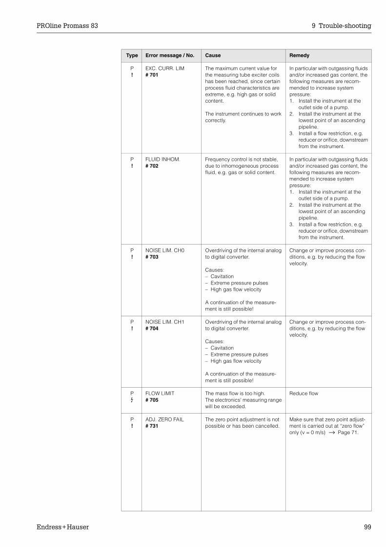
PROline Promass 83 9 Trouble-shooting
Endress+Hauser 99
P!
EXC. CURR. LIM# 701
The maximum current value for the measuring tube exciter coils has been reached, since certain process fluid characteristics are extreme, e.g. high gas or solid content.
The instrument continues to work correctly.
In particular with outgassing fluids and/or increased gas content, the following measures are recom-mended to increase system pressure:1. Install the instrument at the
outlet side of a pump.2. Install the instrument at the
lowest point of an ascending pipeline.
3. Install a flow restriction, e.g. reducer or orifice, downstream from the instrument.
P!
FLUID INHOM.# 702
Frequency control is not stable, due to inhomogeneous process fluid, e.g. gas or solid content.
In particular with outgassing fluids and/or increased gas content, the following measures are recom-mended to increase system pressure:1. Install the instrument at the
outlet side of a pump.2. Install the instrument at the
lowest point of an ascending pipeline.
3. Install a flow restriction, e.g. reducer or orifice, downstream from the instrument.
P!
NOISE LIM. CH0# 703
Overdriving of the internal analog to digital converter.
Causes:– Cavitation– Extreme pressure pulses– High gas flow velocity
A continuation of the measure-ment is still possible!
Change or improve process con-ditions, e.g. by reducing the flow velocity.
P!
NOISE LIM. CH1# 704
Overdriving of the internal analog to digital converter.
Causes:– Cavitation– Extreme pressure pulses– High gas flow velocity
A continuation of the measure-ment is still possible!
Change or improve process con-ditions, e.g. by reducing the flow velocity.
P$
FLOW LIMIT# 705
The mass flow is too high.The electronics' measuring range will be exceeded.
Reduce flow
P!
ADJ. ZERO FAIL# 731
The zero point adjustment is not possible or has been cancelled.
Make sure that zero point adjust-ment is carried out at “zero flow” only (v = 0 m/s) → Page 71.
Type Error message / No. Cause Remedy

9 Trouble-shooting PROline Promass 83
100 Endress+Hauser
9.4 Process errors without messages
Symptoms Rectification
Remark:You may have to change or correct certain settings of the function matrix in order to rectify faults.The functions outlined below, such as DISPLAY DAMPING, for example, are described in detail in the “Description of Device Functions” manual.
Measured value reading fluctuates even though flow is steady.
1. Check the fluid for presence of gas bubbles.2. “TIME CONSTANT” function → increase value
(→ OUTPUTS / CURRENT OUTPUT / CONFIGURATION)3. “DISPLAY DAMPING” function → increase value
(→ USER INTERFACE / CONTROL / BASIC CONFIGURATION)
Flow values are negative, even though the fluid isflowing forwards throughthe pipe.
Change the setting in the “INSTALLATION DIRECTION SENSOR” function accordingly
Measured-value reading or measured-value output pulsates or fluctuates, e.g. because of reciprocating pump, peristaltic pump, diaphragm pump or pump with similar delivery characteristic.
Run the “Pulsating Flow” Quick Setup → Page 63 ff.
If the problem persists despite these measures, a pulsation damper will have to be installed between pump and measuring device.
There are differences between the flowmeter's internal totalizer and the external metering device.
This symptom is due primarily to backflow in the piping, because the pulse output cannot subtract in the “STANDARD or SYMMETRY” measur-ing modes.
The problem can be solved as follows:Allow for flow in both directions. Set the “MEASURING MODE” function to “Pulsating Flow” for the pulse output in question.
Measured value reading shown on display, even though the fluid is at a standstill and the measuring tube is full.
1. Check the fluid for presence of gas bubbles.2. Activate the “ON-VAL. LF-CUTOFF” function, i.e. enter or increase the
value for the creepage (→ BASIC FUNCTION / PROCESSPARA-METER / CONFIGURATION).
The fault cannot be rectified or some other fault not described above has occurred. In these instances, please contact your E+H service organisation.
The following options are available for tackling problems of this nature:
Request the services of an E+H service technicianIf you contact our service organisation to have a service technician sent out, please be ready with the following information:– Brief description of the fault– Nameplate specifications (Page 9 ff.): Order code and serial number
Returning devices to E+HThe procedures on Page 8 must be carried out before you return a flow-meter requiring repair or calibration to Endress+Hauser. Always enclose a duly completed “Declaration of contamination” form with the flowmeter. You will find a preprinted “Declaration of contamina-tion” form at the back of this manual.
Replace transmitter electronicsComponents in the measuring electronics defective → order replacement → Page 103
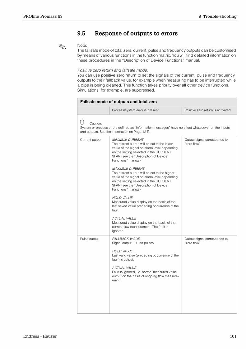
PROline Promass 83 9 Trouble-shooting
Endress+Hauser 101
9.5 Response of outputs to errors
! Note:The failsafe mode of totalizers, current, pulse and frequency outputs can be customised by means of various functions in the function matrix. You will find detailed information on these procedures in the “Description of Device Functions” manual.
Positive zero return and failsafe mode:You can use positive zero return to set the signals of the current, pulse and frequency outputs to their fallback value, for example when measuring has to be interrupted while a pipe is being cleaned. This function takes priority over all other device functions. Simulations, for example, are suppressed.
Failsafe mode of outputs and totalizers
Process/system error is present Positive zero return is activated
" Caution:System or process errors defined as “Information messages” have no effect whatsoever on the inputs and outputs. See the information on Page 42 ff.
Current output MINIMUM CURRENTThe current output will be set to the lower value of the signal on alarm level depending on the setting selected in the CURRENT SPAN (see the “Description of Device Functions” manual).
MAXIMUM CURRENT The current output will be set to the higher value of the signal on alarm level depending on the setting selected in the CURRENT SPAN (see the “Description of Device Functions” manual).
HOLD VALUEMeasured value display on the basis of the last saved value preceding occurrence of the fault.
ACTUAL VALUE Measured value display on the basis of the current flow measurement. The fault is ignored.
Output signal corresponds to “zero flow”
Pulse output FALLBACK VALUESignal output → no pulses
HOLD VALUELast valid value (preceding occurrence of the fault) is output.
ACTUAL VALUEFault is ignored, i.e. normal measured value output on the basis of ongoing flow measure-ment.
Output signal corresponds to “zero flow”
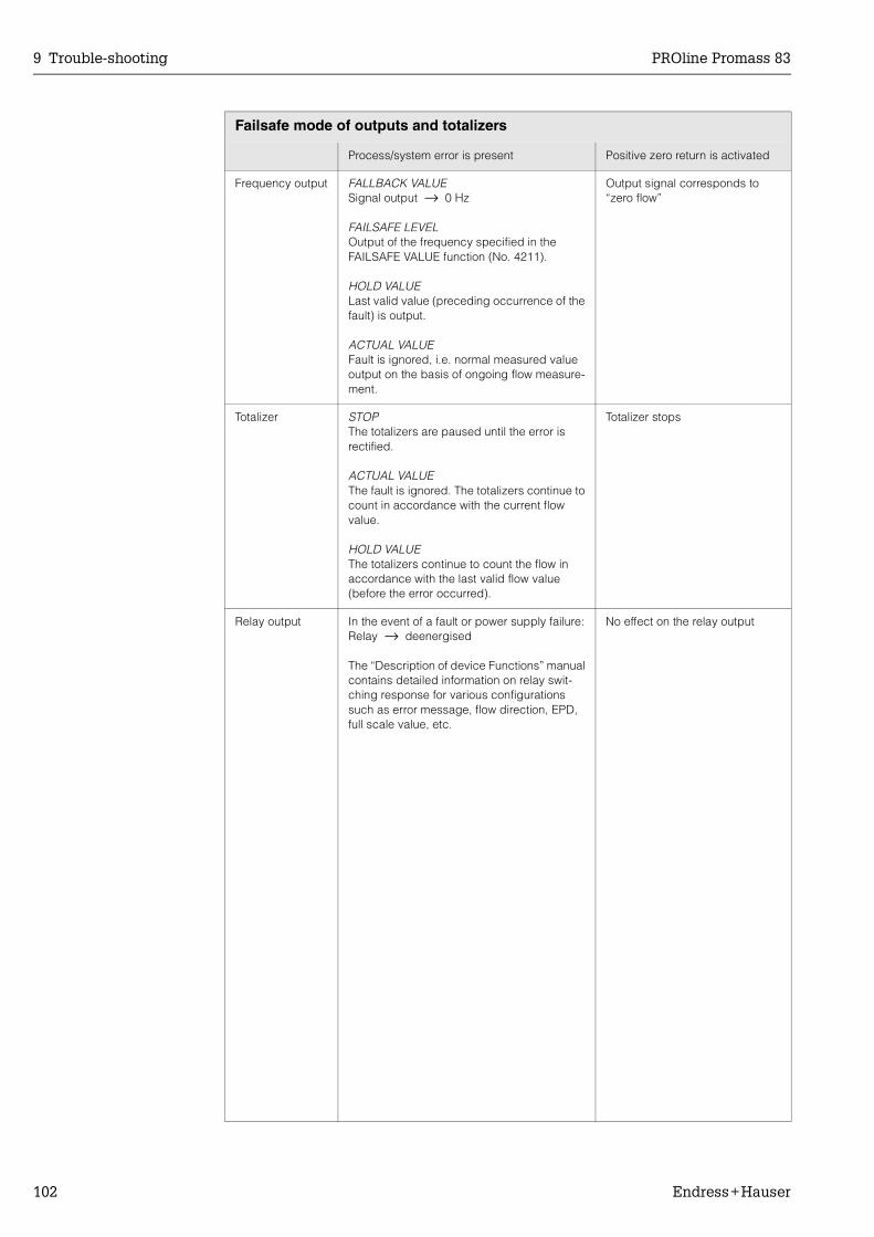
9 Trouble-shooting PROline Promass 83
102 Endress+Hauser
Frequency output FALLBACK VALUESignal output → 0 Hz
FAILSAFE LEVELOutput of the frequency specified in the FAILSAFE VALUE function (No. 4211).
HOLD VALUELast valid value (preceding occurrence of the fault) is output.
ACTUAL VALUEFault is ignored, i.e. normal measured value output on the basis of ongoing flow measure-ment.
Output signal corresponds to “zero flow”
Totalizer STOPThe totalizers are paused until the error is rectified.
ACTUAL VALUEThe fault is ignored. The totalizers continue to count in accordance with the current flow value.
HOLD VALUEThe totalizers continue to count the flow in accordance with the last valid flow value (before the error occurred).
Totalizer stops
Relay output In the event of a fault or power supply failure:Relay → deenergised
The “Description of device Functions” manual contains detailed information on relay swit-ching response for various configurations such as error message, flow direction, EPD, full scale value, etc.
No effect on the relay output
Failsafe mode of outputs and totalizers
Process/system error is present Positive zero return is activated

PROline Promass 83 9 Trouble-shooting
Endress+Hauser 103
9.6 Spare parts
Section 9.1 contains a detailed trouble-shooting guide. The measuring device, more-over, provides additional support in the form of continuous self-diagnosis and error messages.Fault rectification can entail replacing defective components with tested spare parts. The illustration below shows the available scope of spare parts.
! Note:You can order spare parts directly from your E+H service organisation by providing the serial number printed on the transmitter's nameplate (see Page 9).
Spare parts are shipped as sets comprising the following parts:• Spare part• Additional parts, small items (threaded fasteners, etc.)• Mounting instructions• Packaging
Fig. 39: Spare parts for Promass 83 transmitter (field and wall-mount housings)
1 Power unit board (85...260 V AC, 20...55 V AC, 16...62 V DC)2 Amplifier board3 I/O board (COM module), flexible assignment4 Pluggable input/output submodules (ordering structure → Page 87)5 I/O board (COM module), permanent assignment6 S-DAT (sensor data memory)7 T-DAT (transmitter data memory)8 F-Chip (function chip for optional software)9 Display module
1
2
3
4
9
6
7
8
8
INPUT/OUTPUT 2
INPUT/OUTPUT 3
INPUT/OUTPUT 4
5
F06-
83xx
xxxx
-03-
06-0
6-xx
-000
9 Trouble-shooting PROline Promass 83
104 Endress+Hauser
9.7 Removing and installing printed circuit boards
Field housing: removing and installing printed circuit boards (Fig. 40)
# Warning:• Risk of electric shock. Exposed components carry dangerous voltages. Make sure
that the power supply is switched off before you remove the cover of the electronics compartment.
• Risk of damaging electronic components (ESD protection). Static electricity can damage electronic components or impair their operability. Use a workplace with a grounded working surface purposely built for electrostatically sensitive devices!
• If you cannot guarantee that the dielectric strength of the device is maintained in the following steps, then an appropriate inspection must be carried out in accordance with the manufacturer’s specifications.
1. Unscrew cover of the electronics compartment from the transmitter housing.2. Remove the local display (1) as follows:
– Press in the latches (1.1) at the side and remove the display module.– Disconnect the ribbon cable (1.2) of the display module from the amplifier board.
3. Remove the screws and remove the cover (2) from the electronics compartment.4. Remove power unit board (4) and I/O board (6, 7):
Insert a thin pin into the hole (3) provided for the purpose and pull the board clear of its holder.
5. Remove submodules (6.2):No tools are required for removing the submodules (inputs/outputs) from the I/O board. Installation is also a no-tools operation.
" Caution:Only certain combinations of submodules on the I/O board are permissible (see Page 29). The individual slots are marked and correspond to certain terminals in the connection compartment of the transmitter:
“INPUT / OUTPUT 2” slot = terminals 24 / 25“INPUT / OUTPUT 3” slot = terminals 22 / 23“INPUT / OUTPUT 4” slot = terminals 20 / 21
6. Remove amplifier board (5):– Disconnect the plug of the sensor signal cable (5.1) including S-DAT (5.3) from
the board.– Gently disconnect the plug of the excitation current cable (5.2) from the board,
i.e. without moving it back and forward.– Insert a thin pin into the hole (3) provided for the purpose and pull the board clear
of its holder.
7. Installation is the reverse of the removal procedure.
" Caution:Use only original Endress+Hauser parts.

PROline Promass 83 9 Trouble-shooting
Endress+Hauser 105
Fig. 40: Field housing: removing and installing printed circuit boards
1 Local display1.1 Latch1.2 Ribbon cable (display module)2 Screws of electronics compartment cover3 Aperture for installing/removing boards4 Power unit board5 Amplifier board5.1 Signal cable (sensor)5.2 Excitation current cable (sensor)5.3 S-DAT (sensor data memory)5.4 T-DAT (transmitter data memory)6 I/O board (flexible assignment)6.1 F-Chip (function chip for optional software)6.2 Pluggable submodules (status input and current input, current output, frequency output and relay out-
put)7 I/O board (permanent assignment)7.1 F-Chip (function chip for optional software)
4
5
6
6.2
3
3
3
2
1
1.2
5.1
5.35.4
5.2
1.1
INPUT/OUTPUT 2
INPUT/OUTPUT 3
INPUT/OUTPUT 4
6.1
7
7.1
F06-
83xx
xxxx
-03-
06-0
6-xx
-001
9 Trouble-shooting PROline Promass 83
106 Endress+Hauser
Wall-mount housing: removing and installing printed circuit boards (Fig. 41)
# Warning:• Risk of electric shock. Exposed components carry dangerous voltages. Make sure
that the power supply is switched off before you remove the cover of the electronics compartment.
• Risk of damaging electronic components (ESD protection). Static electricity can damage electronic components or impair their operability. Use a workplace with a grounded working surface, purposely built for electrostatically sensitive devices!
1. Remove the screws and open the hinged cover (1) of the housing.2. Remove the screws securing the electronics module (2). Then push up electronics
module and pull it as far as possible out of the wall-mount housing.3. Disconnect the following cable plugs from amplifier board (7):
– Sensor signal cable plug (7.1) including S-DAT (7.3)– Unplug excitation current cable (7.2). Gently disconnect the plug, i.e. without
moving it back and forward.– Ribbon cable plug (3) of the display module.
4. Remove the cover (4) from the electronics compartment by losening the screws.5. Remove the boards (6, 7, 8, 9):
Insert a thin pin into the hole (5) provided for the purpose and pull the board clear of its holder.
6. Remove submodules (8.2):No tools are required for removing the submodules (inputs/outputs) from the I/O board. Installation is also a no-tools operation.
" Caution:Only certain combinations of submodules on the I/O board are permissible (see Page 29). The individual slots are marked and correspond to certain terminals in the connection compartment of the transmitter:
“INPUT / OUTPUT 2” slot = terminals 24 / 25“INPUT / OUTPUT 3” slot = terminals 22 / 23“INPUT / OUTPUT 4” slot = terminals 20 / 21
7. Installation is the reverse of the removal procedure.
" Caution:Use only original Endress+Hauser parts.
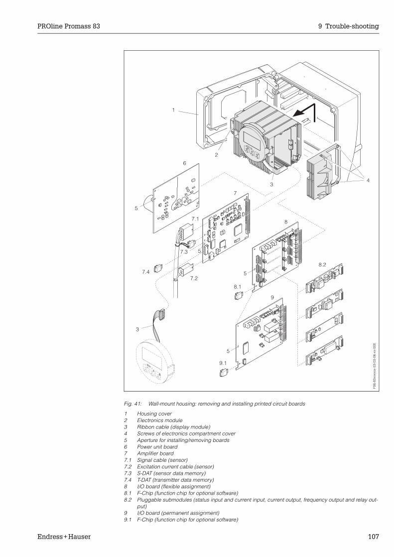
PROline Promass 83 9 Trouble-shooting
Endress+Hauser 107
Fig. 41: Wall-mount housing: removing and installing printed circuit boards
1 Housing cover2 Electronics module3 Ribbon cable (display module)4 Screws of electronics compartment cover5 Aperture for installing/removing boards6 Power unit board7 Amplifier board7.1 Signal cable (sensor)7.2 Excitation current cable (sensor)7.3 S-DAT (sensor data memory)7.4 T-DAT (transmitter data memory)8 I/O board (flexible assignment)8.1 F-Chip (function chip for optional software)8.2 Pluggable submodules (status input and current input, current output, frequency output and relay out-
put)9 I/O board (permanent assignment)9.1 F-Chip (function chip for optional software)
34
1
2
3
6
7
8
8.2
9
5
5
7.1
7.3
7.47.2
INPUT/OUTPUT 2
INPUT/OUTPUT 3
INPUT/OUTPUT 4
8.1
5
5
9.1
F06-
83xx
xxxx
-03-
03-0
6-xx
-000
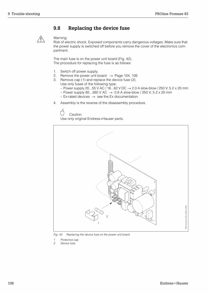
9 Trouble-shooting PROline Promass 83
108 Endress+Hauser
9.8 Replacing the device fuse
# Warning:Risk of electric shock. Exposed components carry dangerous voltages. Make sure that the power supply is switched off before you remove the cover of the electronics com-partment.
The main fuse is on the power unit board (Fig. 42).The procedure for replacing the fuse is as follows:
1. Switch off power supply.2. Remove the power unit board → Page 104, 1063. Remove cap (1) and replace the device fuse (2).
Use only fuses of the following type:– Power supply 20...55 V AC / 16...62 V DC → 2.0 A slow-blow / 250 V; 5.2 x 20 mm– Power supply 85...260 V AC → 0.8 A slow-blow / 250 V; 5.2 x 20 mm– Ex-rated devices → see the Ex documentation.
4. Assembly is the reverse of the disassembly procedure.
" Caution:Use only original Endress+Hauser parts.
Fig. 42: Replacing the device fuse on the power unit board
1 Protective cap2 Device fuse
F06-
xxxx
xxxx
-03-
xx-0
6-xx
-000

PROline Promass 83 9 Trouble-shooting
Endress+Hauser 109
9.9 Software history
Software version / date
Changes to software Changes to documentation
Amplifier
V 1.00.XX / 11.2000 Original software
Compatible with:– FieldTool– HART communicator DXR 275
(OS 4.6 and higher) with rev. 1, DD 1.
−
V 1.01.00 / 03.2001V 1.01.01 / 05.2001
Software adaptation −
V 1.02.00 / 06.2001 Software expansion:New functionalities
• General instrument functions• “Batching” software function• “Concentration measurement”
software function• “Advanced Diagnostics”
software function• HART operating via Universal
Commands and Common Prac-tice Commands
V 1.02.01 / 11.2001 Software adaptation −
V 1.02.02 / 04.2002 Software expansion Promass H
v 1.04.xx / 08.2002 Software expansion Promass E
V 1.05.xx / 03.2003 Software adaptation −
V 1.06.xx / 10.2003 Software expansion
New functionalities
Compatible with:
• Language groups• Flow direction pulse output
selectable• Adjustments to FieldCheck and
Simubox• Concentration measurement
with 4 data records• Viscosity measurement with
temperature compensation• Acquisition start via status input
for advanced diagnostics
• Operation hours counter• Intensity of background illumi-
nation adjustable• Simulation pulse output• Counter for access code
• ToF-Tool FieldTool package (the latest SW version can be down-loaded under: www.tof-field-tool.endress.com
• HART Communicator DXR 375 with Device Rev. 5, DD Rev. 1

9 Trouble-shooting PROline Promass 83
110 Endress+Hauser
! Note:Up or downloading a software version normally requires a special service software.
Communication (I/O)
V 1.00.00 / 11.2000 Original software −
V 1.02.00 / 06.2001 Software expansion:New functionalities:
• “Batching” software function• “Pulse width” software function
V 1.02.01 / 03.2003 Software adaptation −
V 1.03.00 / 10.2003 Software expansion:
New functionalities:
• SIL 2
• Current input• Simulation pulse output
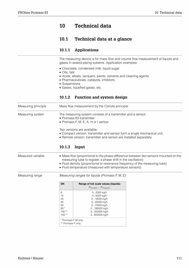
PROline Promass 83 10 Technical data
Endress+Hauser 111
10 Technical data
10.1 Technical data at a glance
10.1.1 Applications
The measuring device is for mass flow and volume flow measurement of liquids and gases in sealed piping systems. Application examples:
• Chocolate, condensed milk, liquid sugar• Oils, fats• Acids, alkalis, lacquers, paints, solvents and cleaning agents• Pharmaceuticals, catalysts, inhibitors• Suspensions• Gases, liquefied gases, etc.
10.1.2 Function and system design
Measuring principle Mass flow measurement by the Coriolis principle
Measuring system The measuring system consists of a transmitter and a sensor:• Promass 83 transmitter• Promass F, M, E, A, H or I sensor
Two versions are available:• Compact version: transmitter and sensor form a single mechanical unit.• Remote version: transmitter and sensor are installed separately.
10.1.3 Input
Measured variable • Mass flow (proportional to the phase difference between two sensors mounted on the measuring tube to register a phase shift in the oscillation)
• Fluid density (proportional to resonance frequency of the measuring tube)• Fluid temperature (measured with temperature sensors)
Measuring range Measuring ranges for liquids (Promass F, M, E):
DN Range of full scale values (liquids)...
81525405080 *100 **150 **
0...2000 kg/h0...6500 kg/h0...18000 kg/h0...45000 kg/h0...70000 kg/h
0...180000 kg/h0...350000 kg/h0...800000 kg/h
* Promass F, M only** Promass F only
m· min F( ) m· max F( )
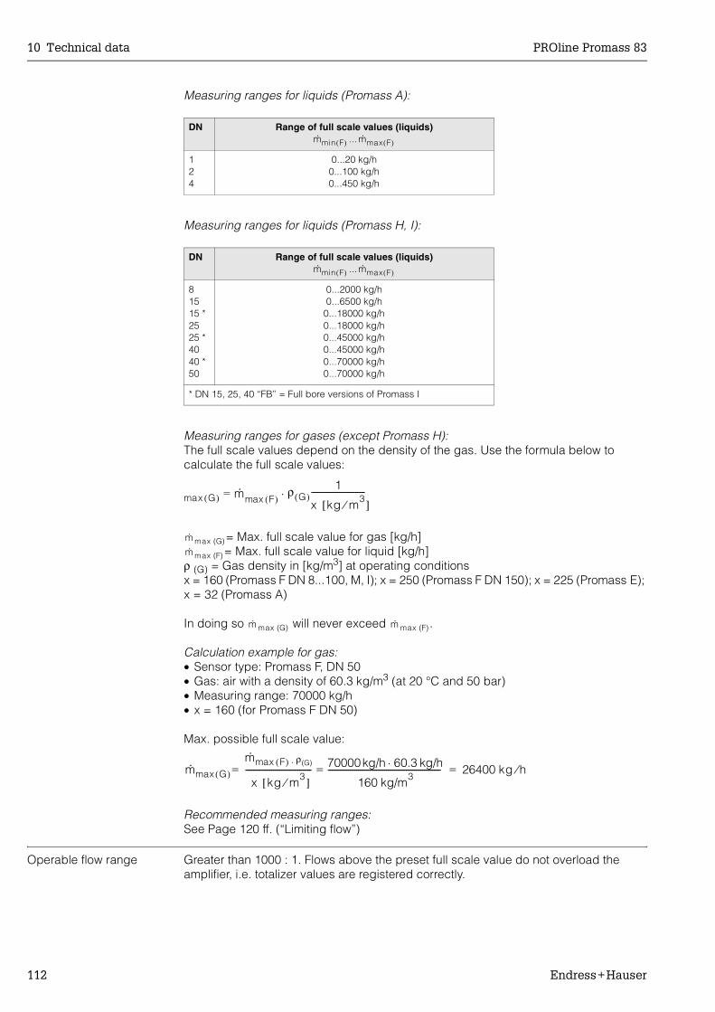
10 Technical data PROline Promass 83
112 Endress+Hauser
Measuring ranges for liquids (Promass A):
Measuring ranges for liquids (Promass H, I):
Measuring ranges for gases (except Promass H):The full scale values depend on the density of the gas. Use the formula below to calculate the full scale values:
= Max. full scale value for gas [kg/h]= Max. full scale value for liquid [kg/h]
ρ (G) = Gas density in [kg/m3] at operating conditionsx = 160 (Promass F DN 8...100, M, I); x = 250 (Promass F DN 150); x = 225 (Promass E); x = 32 (Promass A)
In doing so will never exceed .
Calculation example for gas:• Sensor type: Promass F, DN 50• Gas: air with a density of 60.3 kg/m3 (at 20 °C and 50 bar)• Measuring range: 70000 kg/h• x = 160 (for Promass F DN 50)
Max. possible full scale value:
Recommended measuring ranges:See Page 120 ff. (“Limiting flow”)
Operable flow range Greater than 1000 : 1. Flows above the preset full scale value do not overload the amplifier, i.e. totalizer values are registered correctly.
DN Range of full scale values (liquids)...
124
0...20 kg/h0...100 kg/h0...450 kg/h
DN Range of full scale values (liquids)...
81515 *2525 *4040 *50
0...2000 kg/h0...6500 kg/h
0...18000 kg/h0...18000 kg/h0...45000 kg/h0...45000 kg/h0...70000 kg/h0...70000 kg/h
* DN 15, 25, 40 “FB” = Full bore versions of Promass I
m· min F( ) m· max F( )
m· min F( ) m· max F( )
max G( ) m·= max F( )ρ G( )
1
x kg m3⁄[ ]---------------------------⋅
m· max (G)m· max (F)
m· max (G) m· max (F)
m· max G( )
m· max F( ) ρ(G)⋅
x kg m3⁄[ ]--------------------------------- 70000kg/h 60.3 kg/h⋅
160 kg/m3-------------------------------------------------------- 26400 kg h⁄===
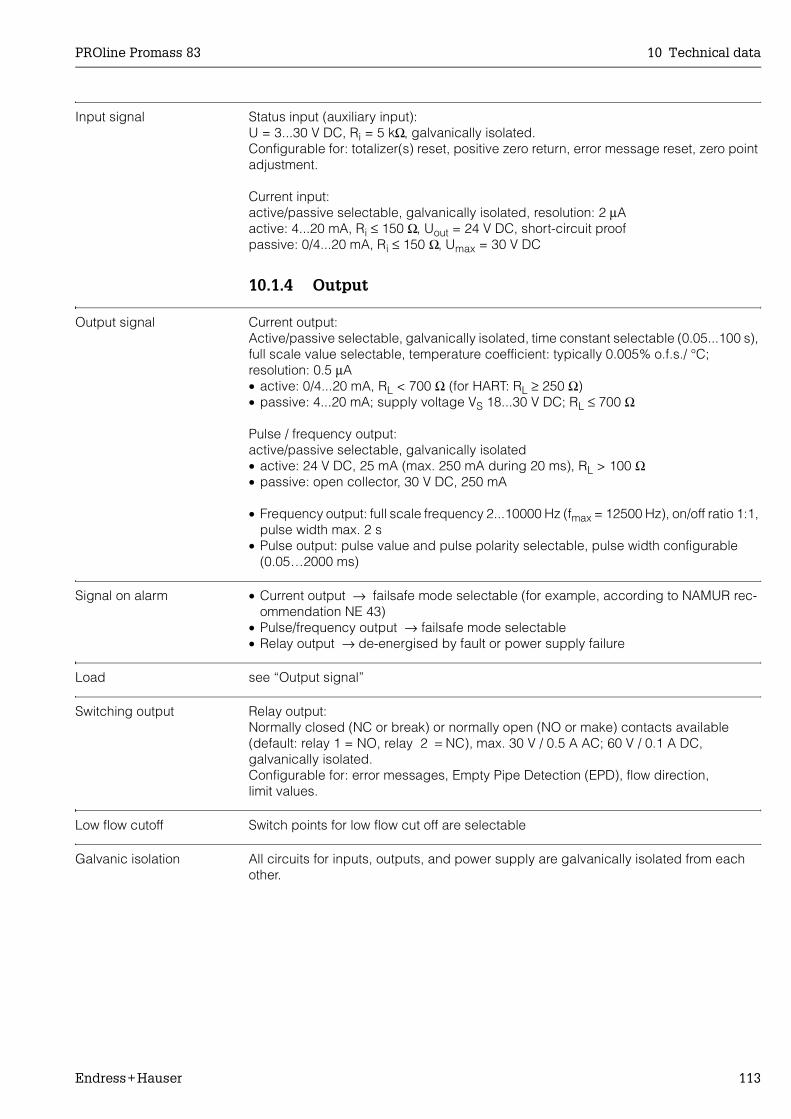
PROline Promass 83 10 Technical data
Endress+Hauser 113
Input signal Status input (auxiliary input):U = 3...30 V DC, Ri = 5 kΩ, galvanically isolated.Configurable for: totalizer(s) reset, positive zero return, error message reset, zero point adjustment.
Current input:active/passive selectable, galvanically isolated, resolution: 2 µAactive: 4...20 mA, Ri ≤ 150 Ω, Uout = 24 V DC, short-circuit proofpassive: 0/4...20 mA, Ri ≤ 150 Ω, Umax = 30 V DC
10.1.4 Output
Output signal Current output:Active/passive selectable, galvanically isolated, time constant selectable (0.05...100 s), full scale value selectable, temperature coefficient: typically 0.005% o.f.s./ °C; resolution: 0.5 µA• active: 0/4...20 mA, RL < 700 Ω (for HART: RL ≥ 250 Ω)• passive: 4...20 mA; supply voltage VS 18...30 V DC; RL ≤ 700 Ω
Pulse / frequency output:active/passive selectable, galvanically isolated• active: 24 V DC, 25 mA (max. 250 mA during 20 ms), RL > 100 Ω• passive: open collector, 30 V DC, 250 mA
• Frequency output: full scale frequency 2...10000 Hz (fmax = 12500 Hz), on/off ratio 1:1, pulse width max. 2 s
• Pulse output: pulse value and pulse polarity selectable, pulse width configurable (0.05…2000 ms)
Signal on alarm • Current output → failsafe mode selectable (for example, according to NAMUR rec-ommendation NE 43)
• Pulse/frequency output → failsafe mode selectable• Relay output → de-energised by fault or power supply failure
Load see “Output signal”
Switching output Relay output:Normally closed (NC or break) or normally open (NO or make) contacts available (default: relay 1 = NO, relay 2 = NC), max. 30 V / 0.5 A AC; 60 V / 0.1 A DC, galvanically isolated.Configurable for: error messages, Empty Pipe Detection (EPD), flow direction, limit values.
Low flow cutoff Switch points for low flow cut off are selectable
Galvanic isolation All circuits for inputs, outputs, and power supply are galvanically isolated from each other.

10 Technical data PROline Promass 83
114 Endress+Hauser
10.1.5 Auxiliary energy
Electrical connections see Page 25 ff.
Supply voltage 85...260 V AC, 45...65 Hz20...55 V AC, 45...65 Hz16...62 V DC
Cable entry Power supply and signal cables (inputs/outputs):• Cable entry M20 x 1.5 (8...12 mm)• Threads for cable entries, PG 13.5 (5...15 mm), 1/2" NPT, G 1/2"
Connecting cable for remote version:• Cable entry M20 x 1.5 (8...12 mm)• Threads for cable entries, PG 13.5 (5...15 mm), 1/2" NPT, G 1/2"
Cable specifications(remote version)
• 6 x 0.38 mm2 PVC cable with common shield and individually shielded cores.• Conductor resistance: ≤ 50 Ω/km• Capacitance: core/shield: ≤ 420 pF/m• Cable length: max. 20 m• Permanent operating temperature: max. +105 °C
Power consumption AC: <15 VA (including sensor)DC: <15 W (including sensor)
Switch-on current:• max. 13.5 A (< 50 ms) at 24 V DC• max. 3 A (< 5 ms) at 260 V AC
Power supply failure Lasting min. 1 power cycle:• EEPROM or T-DAT saves measuring system data if power supply fails.• S-DAT: exchangeable data storage chip which stores the data of the sensor (nominal
diameter, serial number, calibration factor, zero point, etc.)
Potential equalisation No measures necessary
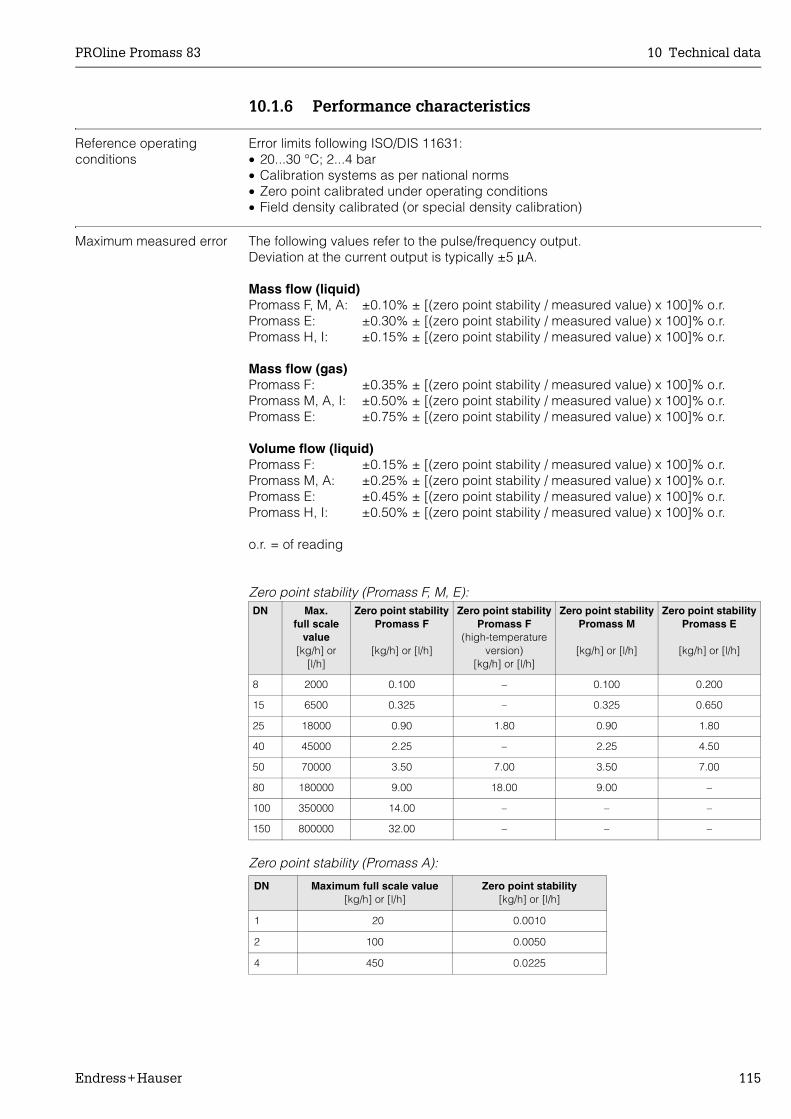
PROline Promass 83 10 Technical data
Endress+Hauser 115
10.1.6 Performance characteristics
Reference operating conditions
Error limits following ISO/DIS 11631:• 20...30 °C; 2...4 bar• Calibration systems as per national norms• Zero point calibrated under operating conditions• Field density calibrated (or special density calibration)
Maximum measured error The following values refer to the pulse/frequency output.Deviation at the current output is typically ±5 µA.
Mass flow (liquid)Promass F, M, A: ±0.10% ± [(zero point stability / measured value) x 100]% o.r.Promass E: ±0.30% ± [(zero point stability / measured value) x 100]% o.r.Promass H, I: ±0.15% ± [(zero point stability / measured value) x 100]% o.r.
Mass flow (gas)Promass F: ±0.35% ± [(zero point stability / measured value) x 100]% o.r.Promass M, A, I: ±0.50% ± [(zero point stability / measured value) x 100]% o.r.Promass E: ±0.75% ± [(zero point stability / measured value) x 100]% o.r.
Volume flow (liquid)Promass F: ±0.15% ± [(zero point stability / measured value) x 100]% o.r.Promass M, A: ±0.25% ± [(zero point stability / measured value) x 100]% o.r.Promass E: ±0.45% ± [(zero point stability / measured value) x 100]% o.r.Promass H, I: ±0.50% ± [(zero point stability / measured value) x 100]% o.r.
o.r. = of reading
Zero point stability (Promass F, M, E):
Zero point stability (Promass A):
DN Max. full scale
value[kg/h] or
[l/h]
Zero point stabilityPromass F
[kg/h] or [l/h]
Zero point stabilityPromass F
(high-temperature version)
[kg/h] or [l/h]
Zero point stabilityPromass M
[kg/h] or [l/h]
Zero point stabilityPromass E
[kg/h] or [l/h]
8 2000 0.100 – 0.100 0.200
15 6500 0.325 – 0.325 0.650
25 18000 0.90 1.80 0.90 1.80
40 45000 2.25 – 2.25 4.50
50 70000 3.50 7.00 3.50 7.00
80 180000 9.00 18.00 9.00 –
100 350000 14.00 – – –
150 800000 32.00 – – –
DN Maximum full scale value[kg/h] or [l/h]
Zero point stability[kg/h] or [l/h]
1 20 0.0010
2 100 0.0050
4 450 0.0225
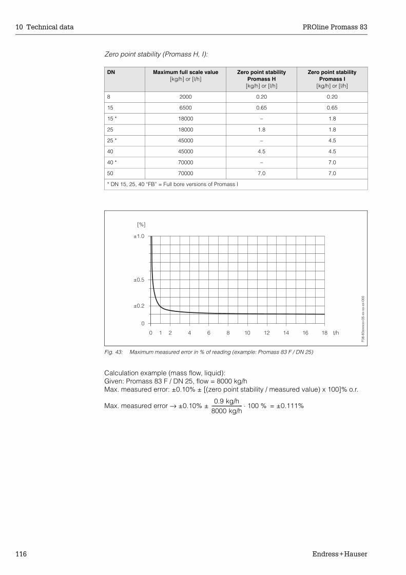
10 Technical data PROline Promass 83
116 Endress+Hauser
Zero point stability (Promass H, I):
Fig. 43: Maximum measured error in % of reading (example: Promass 83 F / DN 25)
Calculation example (mass flow, liquid):Given: Promass 83 F / DN 25, flow = 8000 kg/hMax. measured error: ±0.10% ± [(zero point stability / measured value) x 100]% o.r.
Max. measured error → ±0.10% ± = ±0.111%
DN Maximum full scale value[kg/h] or [l/h]
Zero point stabilityPromass H
[kg/h] or [l/h]
Zero point stabilityPromass I
[kg/h] or [l/h]
8 2000 0.20 0.20
15 6500 0.65 0.65
15 * 18000 – 1.8
25 18000 1.8 1.8
25 * 45000 – 4.5
40 45000 4.5 4.5
40 * 70000 – 7.0
50 70000 7.0 7.0
* DN 15, 25, 40 “FB” = Full bore versions of Promass I
F06-
83xx
xxxx
-05-
xx-x
x-xx
-000
0.9 kg/h8000 kg/h--------------------------- 100 %⋅

PROline Promass 83 10 Technical data
Endress+Hauser 117
Density (liquid)• After field density calibration or under reference conditions:
Promass F: ±0.0005 g/ccPromass M, E, A, H: ±0.0010 g/ccPromass I: ±0.0020 g/cc
• Special density calibration (optional), not for high-temperature version.Calibration range = 0.8...1.8 g/cc, 5...80 °C:Promass F: ±0.001 g/ccPromass M, A, H: ±0.002 g/ccPromass I: ±0.004 g/cc
• Standard calibration:Promass F: ±0.01 g/ccPromass M, E, A, H, I: ±0.02 g/cc
Temperature±0.5 °C ±0.005 x T (T = fluid temperature in °C)
Repeatability Flow measurement• Mass flow (liquid):
Promass F,M,A,H,I: ±0.05% ± [1/2 x (zero point stability / measured value) x100]%o.r.Promass E: ±0.15% ± [1/2 x (zero point stability / measured value) x 100]% o.r.
• Mass flow (gas):Promass F, M, A, I: ±0.25% ± [1/2 x (zero point stability / measured value) x 100]% o.r.Promass E: ±0.35% ± [1/2 x (zero point stability / measured value) x 100]% o.r.
• Volume flow (liquid):Promass F: ±0.05% ± [1/2 x (zero point stability / measured value) x 100]% o.r.Promass M, A: ±0.10% ± [1/2 x (zero point stability / measured value) x 100]% o.r.Promass E: ±0.25% ± [1/2 x (zero point stability / measured value) x 100]% o.r.Promass A: ±0.10% ± [1/2 x (zero point stability / measured value) x 100]% o.r.Promass H, I: ±0.20% ± [1/2 x (zero point stability / measured value) x 100]% o.r.
o.r. = of readingZero point stability: see “Max. measured error”
Calculation example (mass flow, liquid):Given: Promass 83 F / DN 25, flow = 8000 kg/hRepeatability: ±0.05% ± [1/2 x (zero point stability / measured value) x 100]% o.r.
Repeatability → ±0.05% ± 1/2 ⋅ = ±0.0556%
Density measurement (liquid)Promass F: ±0.00025 g/cc (1 g/cc = 1 kg/l)Promass M, H, E, A: ±0.0005 g/ccPromass I: ±0.001 g/cc
Temperature measurement±0.25 °C ±0.0025 x T (T = fluid temperature in °C)
Influence of medium temperature
When there is a difference between the temperature for zero point adjustment and the process temperature, the typical measured error of the Promass sensor is ±0.0002% of the full scale value / °C. The typical measured error of the Promass E sensor is ±0.0003% of the full scale value / °C.
0.9 kg/h8000 kg/h--------------------------- 100 %⋅
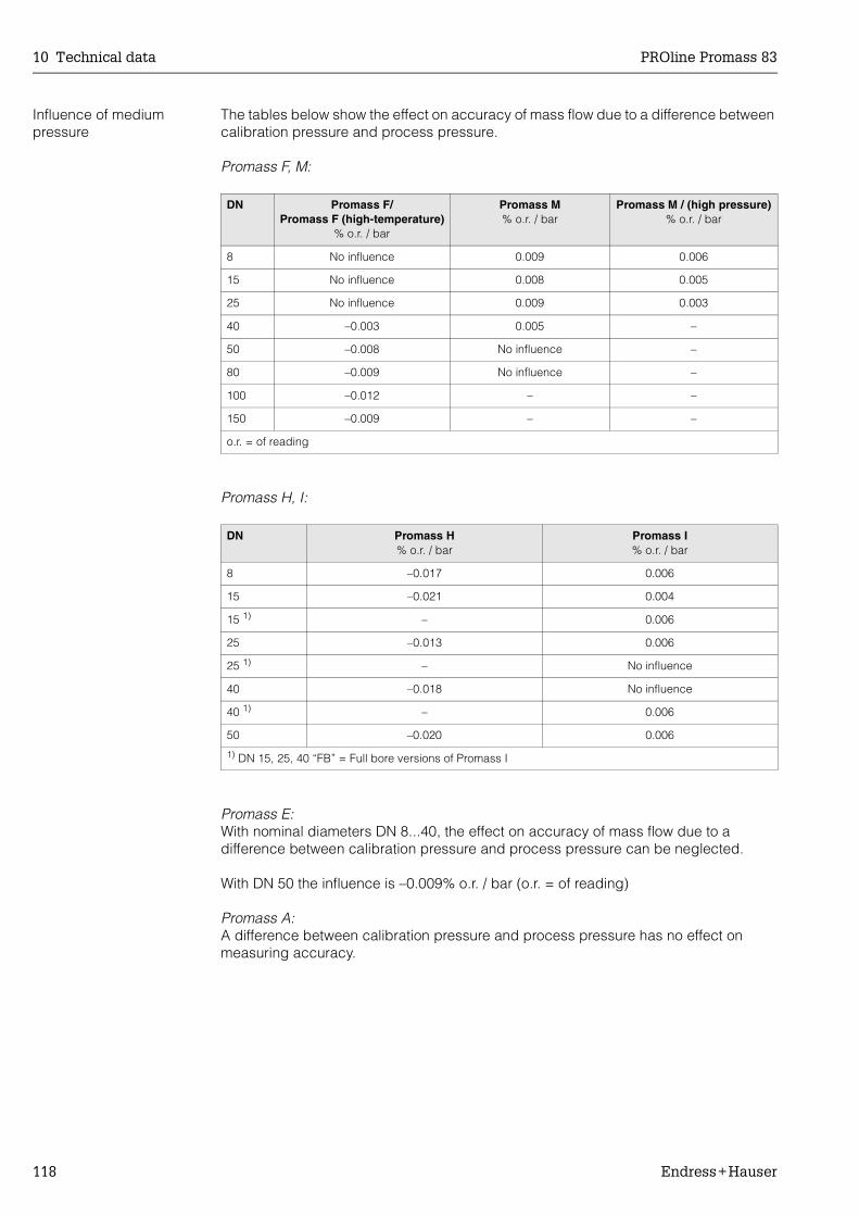
10 Technical data PROline Promass 83
118 Endress+Hauser
Influence of medium pressure
The tables below show the effect on accuracy of mass flow due to a difference between calibration pressure and process pressure.
Promass F, M:
Promass H, I:
Promass E:With nominal diameters DN 8...40, the effect on accuracy of mass flow due to a difference between calibration pressure and process pressure can be neglected.
With DN 50 the influence is –0.009% o.r. / bar (o.r. = of reading)
Promass A:A difference between calibration pressure and process pressure has no effect on measuring accuracy.
DN Promass F/Promass F (high-temperature)
% o.r. / bar
Promass M% o.r. / bar
Promass M / (high pressure)% o.r. / bar
8 No influence 0.009 0.006
15 No influence 0.008 0.005
25 No influence 0.009 0.003
40 –0.003 0.005 –
50 –0.008 No influence –
80 –0.009 No influence –
100 –0.012 – –
150 –0.009 – –
o.r. = of reading
DN Promass H% o.r. / bar
Promass I% o.r. / bar
8 –0.017 0.006
15 –0.021 0.004
15 1) – 0.006
25 –0.013 0.006
25 1) – No influence
40 –0.018 No influence
40 1) – 0.006
50 –0.020 0.006
1) DN 15, 25, 40 “FB” = Full bore versions of Promass I

PROline Promass 83 10 Technical data
Endress+Hauser 119
10.1.7 Operating conditions
Installation
Installation instructions see Page 14 ff.
Inlet and outlet runs There are no installation requirements regarding inlet and outlet runs.
Length of connecting cable
Max. 20 meters (remote version)
System pressure see Page 15
Environment
Ambient temperature Standard: –20...+60 °C (sensor, transmitter)Optional: –40...+60 °C (sensor, transmitter)
Note!• Install the device at a shady location. Avoid direct sunlight, particularly in warm cli-
matic regions.• At ambient temperatures below –20 °C the readability of the display may be impaired.
Storage temperature –40...+80 °C (preferably +20 °C)
Degree of protection Standard: IP 67 (NEMA 4X) for transmitter and sensor
Shock resistance According to IEC 68-2-31
Vibration resistance Acceleration up to 1 g, 10...150 Hz, following IEC 68-2-6
Suitability for CIP cleaning yes
Suitability for SIP cleaning yes
Electromagnetic compatibility (EMC)
To EN 61326/A1 and NAMUR recommendation NE 21
Process
Medium temperature range
Sensor:• Promass F, A, H: –50...+200 °C• Promass F: −50...+350 °C (high-temperature version)• Promass M, I: –50...+150 °C• Promass E: –40...+125 °C
Seals:• Promass F, E, H, I: no internal seals• Promass M: Viton –15...200 °C; EPDM –40...+160 °C; silicon –60...+200 °C;
Kalrez –20...+275 °C; FEP-jacketed (not for gas applications): –60...+200 °C• Promass A (only for mounting sets with threaded connections): Viton –15...200 °C;
EPDM –40...+275 °C; silicon –60...+200 °C; Kalrez –20...+275 °C
10 Technical data PROline Promass 83
120 Endress+Hauser
Limiting medium pressure range (rated pressure)
The material load curves (pressure-temperature diagrams) for the process connections are to be found in the following documents:
• Technical Information Promass 80/83 F, M (TI 053D/06/en)• Technical Information Promass 80/83 E (TI 061D/06/en)• Technical Information Promass 80/83 A (TI 054D/06/en)• Technical Information Promass 80/83 H, I (TI 052D/06/en)
Pressure ranges of secondary containment:• Promass F: DN 8...50: 40 bar or 600 psi; DN 80: 25 bar or 375 psi;
DN 100...150: 16 bar or 250 psi• Promass M: 100 bar or 1500 psi• Promass E: No secondary containment• Promass A: 25 bar or 375 psi• Promass H: DN 8...15: 25 bar or 375 psi; DN 25...50: 16 bar or 250 psi• Promass I: 40 bar or 600 psi
Limiting flow See Page 111 ff. (“Measuring range”)
Select nominal diameter by optimising between required flow range and permissible pressure loss. See Page 111 for a list of max. possible full scale values.• The minimum recommended full scale value is approx. 1/20 of the max. full scale
value.• In most applications, 20...50% of the maximum full scale value can be considered
ideal.• Select a lower full scale value for abrasive substances such as fluids with entrained
solids (flow velocity < 1 m/s). • For gas measurement the following rules apply:
– Flow velocity in the measuring tubes should not be more than half the sonic velocity (0.5 Mach).
– The maximum mass flow depends on the density of the gas (see formula on Page 112)

PROline Promass 83 10 Technical data
Endress+Hauser 121
Pressure loss Pressure loss depends on the properties of the fluid and on its flow. The following formulas can be used to approximately calculate the pressure loss:
Pressure loss formulas for Promass F, M and E
Pressure loss formulas for Promass A, H and I
Reynolds number
Re ≥ 2300 1)
Re < 2300
∆p = pressure loss [mbar]υ = kinematic viscosity [m2/s]
= mass flow [kg/s]
ρ = fluid density [kg/m3]d = inside diameter of measuring tubes [m]K...K2 = constants (depending on nominal diameter)
1) To compute the pressure loss for gases, always use the formula for Re ≥ 2300.
Reynolds number
Re ≥ 2300 1)
Re < 2300
∆p = pressure loss [mbar]υ = kinematic viscosity [m2/s]
= mass flow [kg/s]
ρ = fluid density [kg/m3]d = inside diameter of measuring tubes [m]K...K3 = constants (depending on nominal diameter)
1) To compute the pressure loss for gases, always use the formula for Re ≥ 2300.
Re 2 m·⋅π d υ ρ⋅ ⋅ ⋅---------------------------=
∆p K υ0.25 m· 1.85 ρ 0.86–⋅ ⋅ ⋅=
∆p K1 υ m· K2 υ⋅ 0.25 m· 2⋅ρ
-------------------------------------+⋅ ⋅=
m·
Re 4 m·⋅π d υ ρ⋅ ⋅ ⋅---------------------------=
∆p K υ0.25 m· 1.75 ρ 0.75– K3 m· 2⋅ρ
--------------------+⋅ ⋅ ⋅=
∆p K1 υ m· K3 m· 2⋅ρ
--------------------+⋅ ⋅=
m·
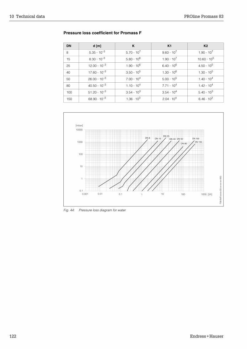
10 Technical data PROline Promass 83
122 Endress+Hauser
Pressure loss coefficient for Promass F
Fig. 44: Pressure loss diagram for water
DN d [m] K K1 K2
8 5.35 ⋅ 10–3 5.70 ⋅ 107 9.60 ⋅ 107 1.90 ⋅ 107
15 8.30 ⋅ 10–3 5.80 ⋅ 106 1.90 ⋅ 107 10.60 ⋅ 105
25 12.00 ⋅ 10–3 1.90 ⋅ 106 6.40 ⋅ 106 4.50 ⋅ 105
40 17.60 ⋅ 10–3 3.50 ⋅ 105 1.30 ⋅ 106 1.30 ⋅ 105
50 26.00 ⋅ 10–3 7.00 ⋅ 104 5.00 ⋅ 105 1.40 ⋅ 104
80 40.50 ⋅ 10–3 1.10 ⋅ 104 7.71 ⋅ 104 1.42 ⋅ 104
100 51.20 ⋅ 10–3 3.54 ⋅ 103 3.54 ⋅ 104 5.40 ⋅ 103
150 68.90 ⋅ 10–3 1.36 ⋅ 103 2.04 ⋅ 104 6.46 ⋅ 102
F06-
8xFx
xxxx
-05-
xx-x
x-xx
-000
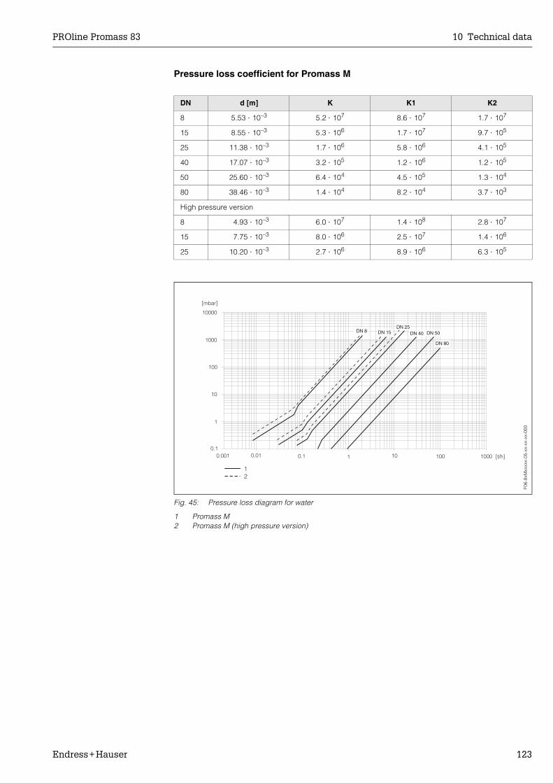
PROline Promass 83 10 Technical data
Endress+Hauser 123
Pressure loss coefficient for Promass M
Fig. 45: Pressure loss diagram for water
1 Promass M2 Promass M (high pressure version)
DN d [m] K K1 K2
8 5.53 ⋅ 10–3 5.2 ⋅ 107 8.6 ⋅ 107 1.7 ⋅ 107
15 8.55 ⋅ 10–3 5.3 ⋅ 106 1.7 ⋅ 107 9.7 ⋅ 105
25 11.38 ⋅ 10–3 1.7 ⋅ 106 5.8 ⋅ 106 4.1 ⋅ 105
40 17.07 ⋅ 10–3 3.2 ⋅ 105 1.2 ⋅ 106 1.2 ⋅ 105
50 25.60 ⋅ 10–3 6.4 ⋅ 104 4.5 ⋅ 105 1.3 ⋅ 104
80 38.46 ⋅ 10–3 1.4 ⋅ 104 8.2 ⋅ 104 3.7 ⋅ 103
High pressure version
8 4.93 ⋅ 10–3 6.0 ⋅ 107 1.4 ⋅ 108 2.8 ⋅ 107
15 7.75 ⋅ 10–3 8.0 ⋅ 106 2.5 ⋅ 107 1.4 ⋅ 106
25 10.20 ⋅ 10–3 2.7 ⋅ 106 8.9 ⋅ 106 6.3 ⋅ 105
F06-
8xM
xxxx
x-05
-xx-
xx-x
x-00
0
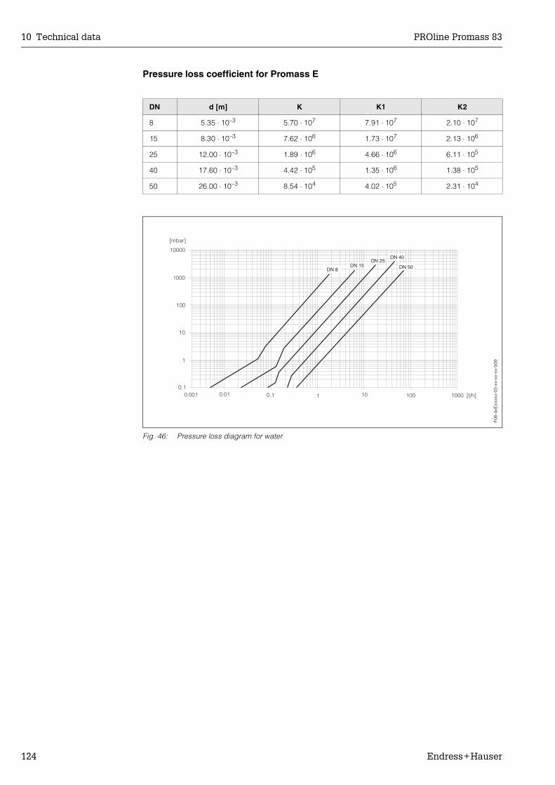
10 Technical data PROline Promass 83
124 Endress+Hauser
Pressure loss coefficient for Promass E
Fig. 46: Pressure loss diagram for water
DN d [m] K K1 K2
8 5.35 ⋅ 10–3 5.70 ⋅ 107 7.91 ⋅ 107 2.10 ⋅ 107
15 8.30 ⋅ 10–3 7.62 ⋅ 106 1.73 ⋅ 107 2.13 ⋅ 106
25 12.00 ⋅ 10–3 1.89 ⋅ 106 4.66 ⋅ 106 6.11 ⋅ 105
40 17.60 ⋅ 10–3 4.42 ⋅ 105 1.35 ⋅ 106 1.38 ⋅ 105
50 26.00 ⋅ 10–3 8.54 ⋅ 104 4.02 ⋅ 105 2.31 ⋅ 104
F06-
4xE
xxxx
x-05
-xx-
xx-x
x-00
9

PROline Promass 83 10 Technical data
Endress+Hauser 125
Pressure loss coefficient for Promass A
Fig. 47: Pressure loss diagram for water
1 Standard version2 High pressure version
DN d [m] K K1 K3
1 1.10 ⋅ 10–3 1.2 ⋅ 1011 1.3 ⋅ 1011 0
2 1.80 ⋅ 10–3 1.6 ⋅ 1010 2.4 ⋅ 1010 0
4 3.50 ⋅ 10–3 9.4 ⋅ 108 2.3 ⋅ 109 0
High pressure version
2 1.40 ⋅ 10–3 5.4 ⋅ 1010 6.6 ⋅ 1010 0
4 3.00 ⋅ 10–3 2.0 ⋅ 109 4.3 ⋅ 109 0
F06-
8xA
xxxx
x-05
-xx-
xx-x
x-00
0

10 Technical data PROline Promass 83
126 Endress+Hauser
Pressure loss coefficient for Promass H
Fig. 48: Pressure loss diagram for water
DN d [m] K K1 K3
8 8.51 ⋅ 10–3 8.04 ⋅ 106 3.28 ⋅ 107 1.15 ⋅ 106
15 12.00 ⋅ 10–3 1.81 ⋅ 106 9.99 ⋅ 106 1.87 ⋅ 105
25 17.60 ⋅ 10–3 3.67 ⋅ 105 2.76 ⋅ 106 4.99 ⋅ 104
40 25.50 ⋅ 10–3 8.75 ⋅ 104 8.67 ⋅ 105 1.22 ⋅ 104
50 40.5 ⋅ 10–3 1.35 ⋅ 104 1.72 ⋅ 105 1.20 ⋅ 103
Pressure loss data includes interface between measuring tube and piping
1000
100
10
1
0.10.01 0.1 1 10 100
[mbar]
[t/h]
DN 40 DN 50DN 25DN 15DN 8
F06-
8xH
xxxx
x-05
-xx-
xx-x
x-00
1
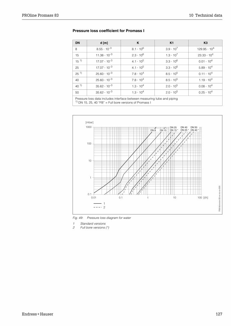
PROline Promass 83 10 Technical data
Endress+Hauser 127
Pressure loss coefficient for Promass I
Fig. 49: Pressure loss diagram for water
1 Standard versions2 Full bore versions (*)
DN d [m] K K1 K3
8 8.55 ⋅ 10–3 8.1 ⋅ 106 3.9 ⋅ 107 129.95 ⋅ 104
15 11.38 ⋅ 10–3 2.3 ⋅ 106 1.3 ⋅ 107 23.33 ⋅ 104
15 1) 17.07 ⋅ 10–3 4.1 ⋅ 105 3.3 ⋅ 106 0.01 ⋅ 104
25 17.07 ⋅ 10–3 4.1 ⋅ 105 3.3 ⋅ 106 5.89 ⋅ 104
25 1) 25.60 ⋅ 10–3 7.8 ⋅ 104 8.5 ⋅ 105 0.11 ⋅ 104
40 25.60 ⋅ 10–3 7.8 ⋅ 104 8.5 ⋅ 105 1.19 ⋅ 104
40 1) 35.62 ⋅ 10–3 1.3 ⋅ 104 2.0 ⋅ 105 0.08 ⋅ 104
50 35.62 ⋅ 10–3 1.3 ⋅ 104 2.0 ⋅ 105 0.25 ⋅ 104
Pressure loss data includes interface between measuring tube and piping1) DN 15, 25, 40 “FB” = Full bore versions of Promass I
F06-
8xIx
xxxx
-05-
xx-x
x-xx
-000
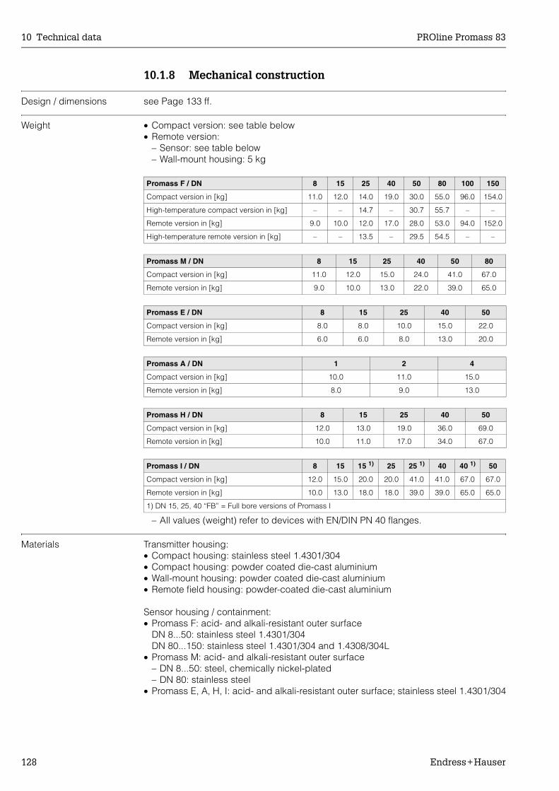
10 Technical data PROline Promass 83
128 Endress+Hauser
10.1.8 Mechanical construction
Design / dimensions see Page 133 ff.
Weight • Compact version: see table below• Remote version:
– Sensor: see table below– Wall-mount housing: 5 kg
– All values (weight) refer to devices with EN/DIN PN 40 flanges.
Materials Transmitter housing:• Compact housing: stainless steel 1.4301/304• Compact housing: powder coated die-cast aluminium• Wall-mount housing: powder coated die-cast aluminium• Remote field housing: powder-coated die-cast aluminium
Sensor housing / containment:• Promass F: acid- and alkali-resistant outer surface
DN 8...50: stainless steel 1.4301/304DN 80...150: stainless steel 1.4301/304 and 1.4308/304L
• Promass M: acid- and alkali-resistant outer surface– DN 8...50: steel, chemically nickel-plated– DN 80: stainless steel
• Promass E, A, H, I: acid- and alkali-resistant outer surface; stainless steel 1.4301/304
Promass F / DN 8 15 25 40 50 80 100 150
Compact version in [kg] 11.0 12.0 14.0 19.0 30.0 55.0 96.0 154.0
High-temperature compact version in [kg] – – 14.7 – 30.7 55.7 – –
Remote version in [kg] 9.0 10.0 12.0 17.0 28.0 53.0 94.0 152.0
High-temperature remote version in [kg] – – 13.5 – 29.5 54.5 – –
Promass M / DN 8 15 25 40 50 80
Compact version in [kg] 11.0 12.0 15.0 24.0 41.0 67.0
Remote version in [kg] 9.0 10.0 13.0 22.0 39.0 65.0
Promass E / DN 8 15 25 40 50
Compact version in [kg] 8.0 8.0 10.0 15.0 22.0
Remote version in [kg] 6.0 6.0 8.0 13.0 20.0
Promass A / DN 1 2 4
Compact version in [kg] 10.0 11.0 15.0
Remote version in [kg] 8.0 9.0 13.0
Promass H / DN 8 15 25 40 50
Compact version in [kg] 12.0 13.0 19.0 36.0 69.0
Remote version in [kg] 10.0 11.0 17.0 34.0 67.0
Promass I / DN 8 15 15 1) 25 25 1) 40 40 1) 50
Compact version in [kg] 12.0 15.0 20.0 20.0 41.0 41.0 67.0 67.0
Remote version in [kg] 10.0 13.0 18.0 18.0 39.0 39.0 65.0 65.0
1) DN 15, 25, 40 “FB” = Full bore versions of Promass I
PROline Promass 83 10 Technical data
Endress+Hauser 129
Connection housing, sensor (remote version):• Stainless steel 1.4301/304 (standard version)• powder coated die-cast aluminium (high-temperature version and version for heating)
Process connections, Promass F:• Flanges EN 1092-1 (DIN 2501) / ANSI B16.5 / JIS B2238 →
stainless steel 1.4404/316L• Flanges EN 1092-1 (DIN 2501) / ANSI B16.5 / JIS B2238 →
Alloy C-22 2.4602/N 06022• Flange DIN 11864-2 Form A (flat flange) → stainless steel 1.4404/316L• Hygienic coupling DIN 11851 / SMS 1145 → stainless steel 1.4404/316L• Couplings ISO 2853 / DIN 11864-1 → stainless steel 1.4404/316L• Tri-Clamp → stainless steel 1.4404/316L
Process connections, Promass F: (high-temperature version):• Flanges EN 1092-1 (DIN 2501) / ANSI B16.5 / JIS B2238 →
stainless steel 1.4404/316L• Flanges EN 1092-1 (DIN 2501) / ANSI B16.5 / JIS B2238 →
Alloy C-22 2.4602 (N 06022)
Process connections, Promass M:• Flanges EN 1092-1 (DIN 2501) / ANSI B16.5 / JIS B2238 →
stainless steel 1.4404/316L, titanium grade 2• Flange DIN 11864-2 Form A (flat flange) → stainless steel 1.4404/316L• PVDF connection to DIN / ANSI / JIS• Hygienic coupling DIN 11851 / SMS 1145 → stainless steel 1.4404/316L• Couplings ISO 2853 / DIN 11864-1 → stainless steel 1.4404/316L• Tri-Clamp → stainless steel 1.4404/316L
Process connections, Promass M (high pressure version):• Connector → stainless steel 1.4404/316L• Couplings → stainless steel 1.4401/316
Process connections, Promass E:• Flanges EN 1092-1 (DIN 2501) / ANSI B16.5 / JIS B2238 →
Stainless steel 1.4404/316L• Flange DIN 11864-2 Form A (flat flange) → Stainless steel 1.4404/316L • VCO connection → Stainless steel 1.4404/316L• Hygienic coupling DIN 11851 / SMS 1145 → Stainless steel 1.4404/316L• Couplings ISO 2853 / DIN 11864-1 → Stainless steel 1.4404/316L• Tri-Clamp → Stainless steel 1.4404/316L
Process connections, Promass A:• Mounting set for flanges EN 1092-1 (DIN 2501) / ANSI B16.5 / JIS B2238 →
stainless steel 1.4539/904L, Alloy C-22 2.4602/N 06022. Loose flanges → stainless steel 1.4404/316L
• VCO coupling → stainless steel 1.4539/904L, Alloy C-22 2.4602/N 06022• Tri-Clamp (1/2") → stainless steel 1.4539/904L• Mounting set for SWAGELOK (1/4", 1/8") → stainless steel 1.4401/316• Mounting set for NPT-F (1/4") → stainless steel 1.4539/904L,
Alloy C-22 2.4602/N 06022
Process connections, Promass H:• Flanges EN 1092-1 (DIN 2501) / ANSI B16.5 / JIS B2238 → stainless steel 1.4301/304,
parts in contact with medium: zirconium 702

10 Technical data PROline Promass 83
130 Endress+Hauser
Process connections, Promass I:• Flanges EN 1092-1 (DIN 2501) / ANSI B16.5 / JIS B2238 → stainless steel 1.4301/304,
parts in contact with medium: titanium grade 9• Flange DIN 11864-2 Form A (flat flange) → titanium grade 2• Hygienic coupling DIN 11851 / SMS 1145 → titanium grade 2• Couplings ISO 2853 / DIN 11864-1 → titanium grade 2• Tri-Clamp → titanium grade 2
Measuring tube(s):• Promass F:
– DN 8...100: stainless steel 1.4539 (904L)– DN 150: stainless steel 1.4404/316L– DN 8...80: Alloy C-22 2.4602/N 06022
• Promass F (high-temperature version):– DN 25, 50, 80: Alloy C-22 2.4602/N 06022
• Promass M:– DN 8...50: titanium grade 9– DN 80: titanium grade 2
• Promass M (high pressure version): titanium grade 9• Promass E: stainless steel 1.4539/904L• Promass A: stainless steel 1.4539/904L, Alloy C-22 2.4602/N 06022• Promass H: zirconium 702/R 60702• Promass I: titanium grade 9
Seals:• Promass F, E, H, I: welded process connections without internal seals• Promass M: Viton, EPDM, silicon, Kalrez, FEP-jacketed (not for gas applications)• Promass A: Viton, EPDM, silicon, Kalrez
Material load diagram The material load curves (pressure-temperature diagrams) for the process connections are to be found in the following documents:
• Technical Information Promass 80/83 F, M (TI 053D/06/en)• Technical Information Promass 80/83 E (TI 061D/06/en)• Technical Information Promass 80/83 A (TI 054D/06/en)• Technical Information Promass 80/83 H, I (TI 052D/06/en)
Process connections see Page 129
10.1.9 Human interface
Display elements • Liquid crystal display: illuminated, four lines with 16 characters per line• Selectable display of different measured values and status variables• 3 totalizers• At ambient temperatures below –20 °C the readability of the display may be impaired.
Operating elements • Local operation with three optical sensors (–, +, E)• Application specific Quick Setup menus for straightforward commissioning
PROline Promass 83 10 Technical data
Endress+Hauser 131
Language group Language groups for operation in different countries:• Western Europe and America:
English, German, Spanish, Italian, French, Dutch and Portuguese• Northern/eastern Europe:
English, Russian, Polish, Norwegian, Finnish, Swedish and Czech• Southern/eastern Asia:
English, Japanese and Indonesian
Remote operation Operation by means of HART protocol
10.1.10 Certificates and approvals
Ex approvals Information about currently available Ex versions (ATEX, FM, CSA) can be supplied by your E+H Sales Centre on request. All explosion protection data are given in a separate documentation which is available upon request.
Sanitary compatibility • 3A authorization (all measuring systems, except Promass H)• EHEDG-tested (Promass A and Promass I only)
Pressure device approval Flow meters with a nominal diameter smaller or equal DN 25 are covered by Art. 3(3) of the European directive 97/23/EG (Pressure Equipment Directive) and are designed according to sound engineer practice. For larger nominal diameter, optional approvals according to Cat. III are available when required (depends on fluid and process pressure).
Functional safety SIL 2:accordance IEC 61508/IEC 61511-1 (FDIS)
CE mark The measuring system is in conformity with the statutory requirements of the EC Direc-tives. Endress+Hauser confirms successful testing of the device by affixing to it the CE mark.
Other standards and guidelines
EN 60529:Degrees of protection by housing (IP code)
EN 61010:Protection Measures for Electrical Equipment for Measurement, Control, Regulation and Laboratory Procedures.
EN 61326/A1 (IEC 1326):Electromagnetic compatibility (EMC requirements)
NAMUR NE 21:Electromagnetic compatibility (EMC) of imdustrial process and laboratory control equipment.
MAMUR NE 43:Standardisation of the signal level for the breakdown information of digital transmitters with analogue output signal.
10 Technical data PROline Promass 83
132 Endress+Hauser
10.1.11 Ordering information
The E+H service organisation can provide detailed ordering information and information on the order codes on request.
10.1.12 Accessories
Various accessories, which can be ordered separately from Endress+Hauser, are avail-able for the transmitter and the sensor (Page 87). The E+H service organisation can provide detailed information on the order codes of your choice.
10.1.13 Documentation
System Information Promass (SI 032D/06/en) Technical Information Promass 80/83 F, M (TI 053D/06/en) Technical Information Promass 80/83 E (TI 061D/06/en) Technical Information Promass 80/83 A (TI 054D/06/en) Technical Information Promass 80/83 H, I (TI 052D/06/en) Description of Device Functions Promass 83 (BA 060D/06/en) Supplementary documentation on Ex-ratings: ATEX, FM, CSA Functional safety manual Promass 80/83 (SD077D/06/en)
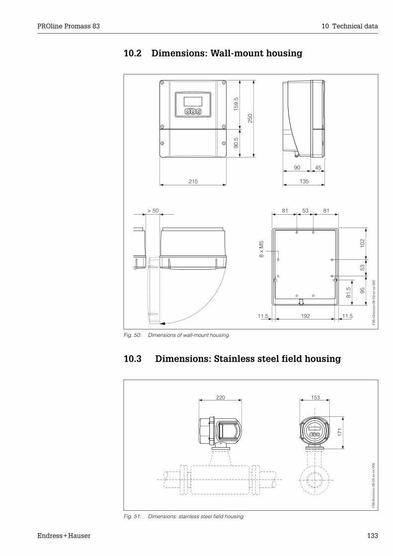
PROline Promass 83 10 Technical data
Endress+Hauser 133
10.2 Dimensions: Wall-mount housing
Fig. 50: Dimensions of wall-mount housing
10.3 Dimensions: Stainless steel field housing
Fig. 51: Dimensions: stainless steel field housing
Esc
E- + 159.
590
.5
250
90
215
> 50 53 8181
135
45
192 11.511.5
102
9553
81.5
8 x
M5
F06-
x3xx
xxxx
-06-
03-x
x-xx
-000
220 153
171
Esc
E- +
F06-
8xxx
xxxx
-06-
00-x
x-xx
-000
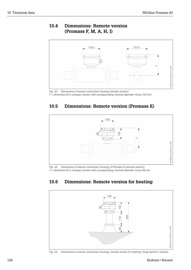
10 Technical data PROline Promass 83
134 Endress+Hauser
10.4 Dimensions: Remote version (Promass F, M, A, H, I)
Fig. 52: Dimensions of sensor connection housing (remote version),T = dimension B in compact version with corresponding nominal diameter minus 153 mm
10.5 Dimensions: Remote version (Promass E)
Fig. 53: Dimensions of sensor connection housing of Promass E (remote version), T = dimension B in compact version with corresponding nominal diameter minus 58 mm
10.6 Dimensions: Remote version for heating
Fig. 54: Dimensions of sensor connection housing, remote version for heating (“long-necked” version)
F06-
8xxx
xxxx
-06-
05-x
x-xx
-000
137.5
T
118.5
T
12910
2
F06-
80E
xxxx
x-06
-05-
xx-x
x-00
0F0
6-8x
xxxx
xx-0
6-05
-xx-
xx-0
06
292
8011
010
2
129
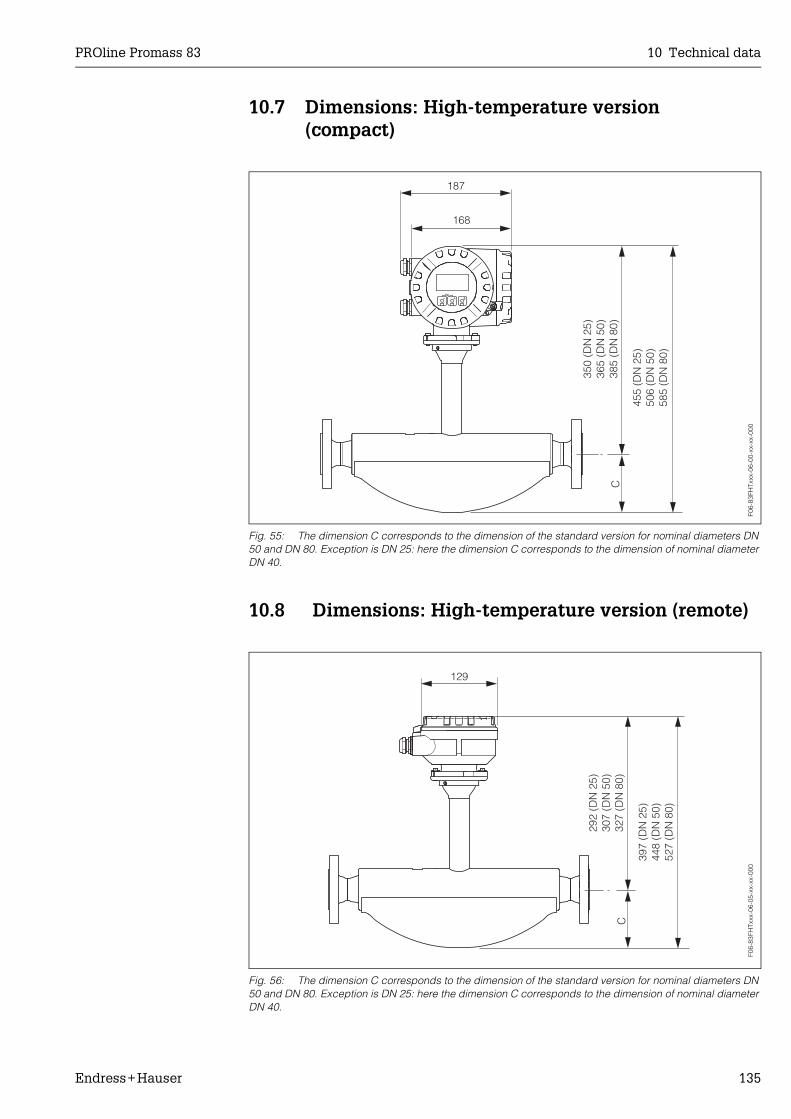
PROline Promass 83 10 Technical data
Endress+Hauser 135
10.7 Dimensions: High-temperature version(compact)
Fig. 55: The dimension C corresponds to the dimension of the standard version for nominal diameters DN 50 and DN 80. Exception is DN 25: here the dimension C corresponds to the dimension of nominal diameter DN 40.
10.8 Dimensions: High-temperature version (remote)
Fig. 56: The dimension C corresponds to the dimension of the standard version for nominal diameters DN 50 and DN 80. Exception is DN 25: here the dimension C corresponds to the dimension of nominal diameter DN 40.
Esc
E- +
168
C
187
350
(DN
25)
365
(DN
50)
385
(DN
80)
455
(DN
25)
506
(DN
50)
585
(DN
80)
F06-
83FH
Txxx
-06-
00-x
x-xx
-000
129
292
(DN
25)
307
(DN
50)
327
(DN
80)
C
397
448
(DN
50)
527
(DN
80)
(DN
25)
F06-
83FH
Txxx
-06-
05-x
x-xx
-000

10 Technical data PROline Promass 83
136 Endress+Hauser
10.9 Dimensions: Promass F
Dimensions Promass F: flange connections EN (DIN), ANSI, JIS
Fig. 57: Dimensions Promass F: flange connections EN (DIN), ANSI, JIS
Flange EN 1092-1 (DIN 2501 / DIN 2512N 1)) / PN 16: 1.4404/316LSurface roughness (flange): EN 1092-1 Form B1 (DIN 2526 Form C), Ra 6.3...12.5 µm
DN A B C G L N S LK U di
100 571 324 247 220 1128 8 x Ø18 20 180 107.1 51.20
150 740 362 378 285 1330 8 x Ø22 22 240 159.3 68.901) Flange with groove to EN 1092-1 Form D (DIN 2512N) available
Flange EN 1092-1 (DIN 2501 / DIN 2512N 1)) / PN 40: 1.4404/316L, Alloy C-22Surface roughness (flange): EN 1092-1 Form B1 (DIN 2526 Form C), Ra 6.3...12.5 µm
DN A B C G L N S LK U di
8 341 266 75 95 370 4 x Ø14 16 65 17.3 5.35
15 341 266 75 95 404 4 x Ø14 16 65 17.3 8.30
25 341 266 75 115 440 4 x Ø14 18 85 28.5 12.00
40 376 271 105 150 550 4 x Ø18 18 110 43.1 17.60
50 424 283 141 165 715 4 x Ø18 20 125 54.5 26.00
80 505 305 200 200 840 8 x Ø18 24 160 82.5 40.50
100 2) 571 324 247 235 1128 8 x Ø22 24 190 107.1 51.20
150 2) 740 362 378 300 1370 8 x Ø26 28 250 159.3 68.901) Flange with groove to EN 1092-1 Form D (DIN 2512N) available2) Not available in Alloy C-22
Flange EN 1092-1 (DIN 2501) / PN 40 (with DN 25 flanges): 1.4404/316LSurface roughness (flange): EN 1092-1 Form B1 (DIN 2526 Form C), Ra 6.3...12.5 µm
DN A B C G L N S LK U di
8 341 266 75 115 440 4 x Ø14 18 85 28.5 5.35
15 341 266 75 115 440 4 x Ø14 18 85 28.5 8.30
F06-
83Fx
xxxx
-06-
00-x
x-xx
-000

PROline Promass 83 10 Technical data
Endress+Hauser 137
Flange EN 1092-1 (DIN 2501 / DIN 2512N 1)) / PN 63: 1.4404/316L, Alloy C-22Surface roughness (flange): EN 1092-1 Form B2 (DIN 2526 Form E), Ra 1.6...3.2 µm
DN A B C G L N S LK U di
50 424 283 141 180 724 4 x Ø22 26 135 54.5 26.00
80 505 305 200 215 875 8 x Ø22 28 170 81.7 40.50
100 2) 571 324 247 250 1128 8 x Ø26 30 200 106.3 51.20
150 2) 740 362 378 345 1410 8 x Ø33 36 280 157.1 68.901) Flange with groove to EN 1092-1 Form D (DIN 2512N) available2) Not available in Alloy C-22
Flange EN 1092-1 (DIN 2501 / DIN 2512N 1)) / PN 100: 1.4404/316L, Alloy C-22Surface roughness (flange): EN 1092-1 Form B2 (DIN 2526 Form E), Ra 1.6...3.2 µm
DN A B C G L N S LK U di
8 341 266 75 105 400 4 x Ø14 20 75 17.3 5.35
15 341 266 75 105 420 4 x Ø14 20 75 17.3 8.30
25 341 266 75 140 470 4 x Ø18 24 100 28.5 12.00
40 376 271 105 170 590 4 x Ø22 26 125 42.5 17.60
50 424 283 141 195 740 4 x Ø26 28 145 53.9 26.00
80 505 305 200 230 885 8 x Ø26 32 180 80.9 40.50
100 2) 571 324 247 265 1128 8 x Ø30 36 210 104.3 51.20
150 2) 740 362 378 355 1450 12 x Ø33 44 290 154.0 68.901) Flange with groove to EN 1092-1 Form D (DIN 2512N) available2) Not available in Alloy C-22
Flange ANSI B16.5 / Cl 150: 1.4404/316L, Alloy C-22Surface roughness (flange): Ra 3.2...6.3 µm
DN A B C G L N S LK U di
8 3/8" 341 266 75 88.9 370 4 x Ø15.7 11.2 60.5 15.7 5.35
15 1/2" 341 266 75 88.9 404 4 x Ø15.7 11.2 60.5 15.7 8.30
25 1" 341 266 75 108.0 440 4 x Ø15.7 14.2 79.2 26.7 12.00
40 1 1/2" 376 271 105 127.0 550 4 x Ø15.7 17.5 98.6 40.9 17.60
50 2" 424 283 141 152.4 715 4 x Ø19.1 19.1 120.7 52.6 26.00
80 3" 505 305 200 190.5 840 4 x Ø19.1 23.9 152.4 78.0 40.50
100 1) 4" 571 324 247 228.6 1128 8 x Ø19.1 23.9 190.5 102.4 51.20
150 1) 6" 6" 740 362 378 279.4 8 x Ø22.4 25.4 241.3 154.2 68.901) Not available in Alloy C-22
Flange ANSI B16.5 / Cl 300: 1.4404/316L, Alloy C-22Surface roughness (flange): Ra 3.2...6.3 µm
DN A B C G L N S LK U di
8 3/8" 341 266 75 95.2 370 4 x Ø15.7 14.2 66.5 15.7 5.35
15 1/2" 341 266 75 95.2 404 4 x Ø15.7 14.2 66.5 15.7 8.30
25 1" 341 266 75 123.9 440 4 x Ø19 17.5 88.9 26.7 12.00
40 1 1/2" 376 271 105 155.4 550 4 x Ø22.3 20.6 114.3 40.9 17.60
50 2" 424 283 141 165.1 715 8 x Ø19 22.3 127.0 52.6 26.00
80 3" 505 305 200 209.5 840 8 x Ø22.3 28.4 168.1 78.0 40.50
100 1) 4" 571 324 247 254.0 1128 8 x Ø22.3 31.7 200.1 102.4 51.20
150 1) 6" 740 362 378 317.5 1417 12xØ22.3 36.5 269.7 154.2 68.901) Not available in Alloy C-22
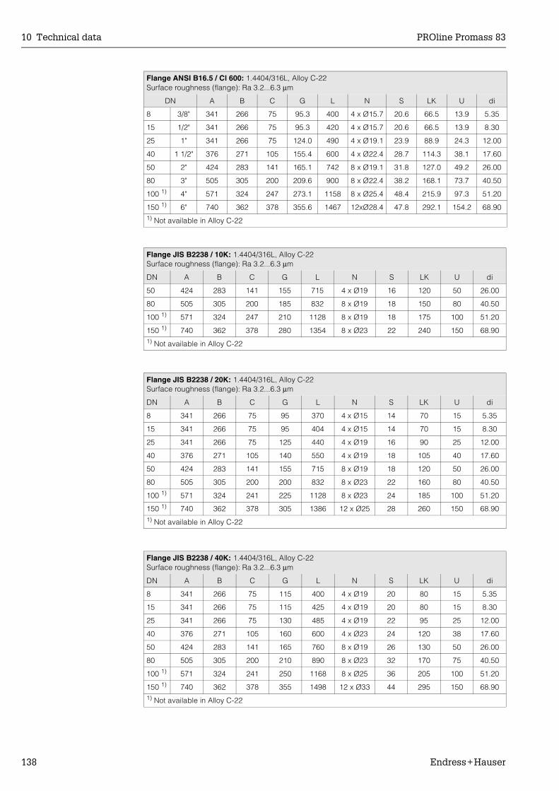
10 Technical data PROline Promass 83
138 Endress+Hauser
Flange ANSI B16.5 / Cl 600: 1.4404/316L, Alloy C-22Surface roughness (flange): Ra 3.2...6.3 µm
DN A B C G L N S LK U di
8 3/8" 341 266 75 95.3 400 4 x Ø15.7 20.6 66.5 13.9 5.35
15 1/2" 341 266 75 95.3 420 4 x Ø15.7 20.6 66.5 13.9 8.30
25 1" 341 266 75 124.0 490 4 x Ø19.1 23.9 88.9 24.3 12.00
40 1 1/2" 376 271 105 155.4 600 4 x Ø22.4 28.7 114.3 38.1 17.60
50 2" 424 283 141 165.1 742 8 x Ø19.1 31.8 127.0 49.2 26.00
80 3" 505 305 200 209.6 900 8 x Ø22.4 38.2 168.1 73.7 40.50
100 1) 4" 571 324 247 273.1 1158 8 x Ø25.4 48.4 215.9 97.3 51.20
150 1) 6" 740 362 378 355.6 1467 12xØ28.4 47.8 292.1 154.2 68.901) Not available in Alloy C-22
Flange JIS B2238 / 10K: 1.4404/316L, Alloy C-22Surface roughness (flange): Ra 3.2...6.3 µm
DN A B C G L N S LK U di
50 424 283 141 155 715 4 x Ø19 16 120 50 26.00
80 505 305 200 185 832 8 x Ø19 18 150 80 40.50
100 1) 571 324 247 210 1128 8 x Ø19 18 175 100 51.20
150 1) 740 362 378 280 1354 8 x Ø23 22 240 150 68.901) Not available in Alloy C-22
Flange JIS B2238 / 20K: 1.4404/316L, Alloy C-22Surface roughness (flange): Ra 3.2...6.3 µm
DN A B C G L N S LK U di
8 341 266 75 95 370 4 x Ø15 14 70 15 5.35
15 341 266 75 95 404 4 x Ø15 14 70 15 8.30
25 341 266 75 125 440 4 x Ø19 16 90 25 12.00
40 376 271 105 140 550 4 x Ø19 18 105 40 17.60
50 424 283 141 155 715 8 x Ø19 18 120 50 26.00
80 505 305 200 200 832 8 x Ø23 22 160 80 40.50
100 1) 571 324 241 225 1128 8 x Ø23 24 185 100 51.20
150 1) 740 362 378 305 1386 12 x Ø25 28 260 150 68.901) Not available in Alloy C-22
Flange JIS B2238 / 40K: 1.4404/316L, Alloy C-22Surface roughness (flange): Ra 3.2...6.3 µm
DN A B C G L N S LK U di
8 341 266 75 115 400 4 x Ø19 20 80 15 5.35
15 341 266 75 115 425 4 x Ø19 20 80 15 8.30
25 341 266 75 130 485 4 x Ø19 22 95 25 12.00
40 376 271 105 160 600 4 x Ø23 24 120 38 17.60
50 424 283 141 165 760 8 x Ø19 26 130 50 26.00
80 505 305 200 210 890 8 x Ø23 32 170 75 40.50
100 1) 571 324 241 250 1168 8 x Ø25 36 205 100 51.20
150 1) 740 362 378 355 1498 12 x Ø33 44 295 150 68.901) Not available in Alloy C-22
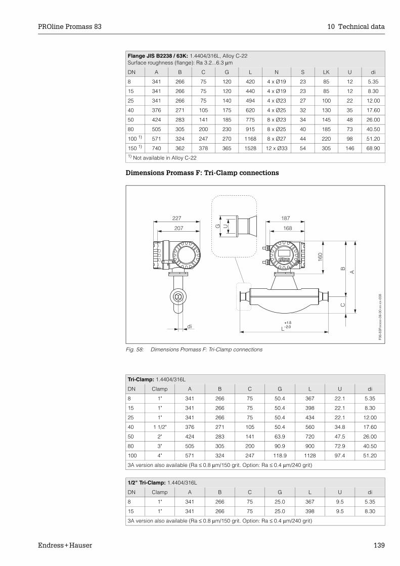
PROline Promass 83 10 Technical data
Endress+Hauser 139
Dimensions Promass F: Tri-Clamp connections
Fig. 58: Dimensions Promass F: Tri-Clamp connections
Flange JIS B2238 / 63K: 1.4404/316L, Alloy C-22Surface roughness (flange): Ra 3.2...6.3 µm
DN A B C G L N S LK U di
8 341 266 75 120 420 4 x Ø19 23 85 12 5.35
15 341 266 75 120 440 4 x Ø19 23 85 12 8.30
25 341 266 75 140 494 4 x Ø23 27 100 22 12.00
40 376 271 105 175 620 4 x Ø25 32 130 35 17.60
50 424 283 141 185 775 8 x Ø23 34 145 48 26.00
80 505 305 200 230 915 8 x Ø25 40 185 73 40.50
100 1) 571 324 247 270 1168 8 x Ø27 44 220 98 51.20
150 1) 740 362 378 365 1528 12 x Ø33 54 305 146 68.901) Not available in Alloy C-22
Tri-Clamp: 1.4404/316L
DN Clamp A B C G L U di
8 1" 341 266 75 50.4 367 22.1 5.35
15 1" 341 266 75 50.4 398 22.1 8.30
25 1" 341 266 75 50.4 434 22.1 12.00
40 1 1/2" 376 271 105 50.4 560 34.8 17.60
50 2" 424 283 141 63.9 720 47.5 26.00
80 3" 505 305 200 90.9 900 72.9 40.50
100 4" 571 324 247 118.9 1128 97.4 51.20
3A version also available (Ra ≤ 0.8 µm/150 grit. Option: Ra ≤ 0.4 µm/240 grit)
1/2" Tri-Clamp: 1.4404/316L
DN Clamp A B C G L U di
8 1" 341 266 75 25.0 367 9.5 5.35
15 1" 341 266 75 25.0 398 9.5 8.30
3A version also available (Ra ≤ 0.8 µm/150 grit. Option: Ra ≤ 0.4 µm/240 grit)
Esc
E- +
227 187
207 168
CB
160
A
Ldi
G U
+1.5–2.0+1.5–2.0
F06-
83Fx
xxxx
-06-
00-x
x-xx
-008

10 Technical data PROline Promass 83
140 Endress+Hauser
Dimensions Promass F: DIN 11851 connections (hygienic coupling)
Fig. 59: Dimensions Promass F: DIN 11851 connections (hygienic coupling)
Hygienic coupling DIN 11851: 1.4404/316L
DN A B C G L U di
8 341 266 75 Rd 34 x 1/8" 367 16 5.35
15 341 266 75 Rd 34 x 1/8" 398 16 8.30
25 341 266 75 Rd 52 x 1/6" 434 26 12.00
40 376 271 105 Rd 65 x 1/6" 560 38 17.60
50 424 283 141 Rd 78 x 1/6" 720 50 26.00
80 505 305 200 Rd 110 x 1/4" 900 81 40.50
100 571 324 247 Rd 130 x 1/4" 1128 100 51.20
3A version also available (Ra ≤ 0.8 µm/150 grit)
Esc
E- +
227 187
207 168
CB
160
A
Ldi
G U+1.5–2.0+1.5–2.0
F06-
83Fx
xxxx
-06-
00-x
x-xx
-009
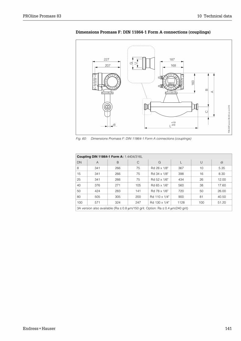
PROline Promass 83 10 Technical data
Endress+Hauser 141
Dimensions Promass F: DIN 11864-1 Form A connections (couplings)
Fig. 60: Dimensions Promass F: DIN 11864-1 Form A connections (couplings)
Coupling DIN 11864-1 Form A: 1.4404/316L
DN A B C G L U di
8 341 266 75 Rd 28 x 1/8" 367 10 5.35
15 341 266 75 Rd 34 x 1/8" 398 16 8.30
25 341 266 75 Rd 52 x 1/6" 434 26 12.00
40 376 271 105 Rd 65 x 1/6" 560 38 17.60
50 424 283 141 Rd 78 x 1/6" 720 50 26.00
80 505 305 200 Rd 110 x 1/4" 900 81 40.50
100 571 324 247 Rd 130 x 1/4" 1128 100 51.20
3A version also available (Ra ≤ 0.8 µm/150 grit. Option: Ra ≤ 0.4 µm/240 grit)
Esc
E- +
227 187
207 168
CB
160
A
Ldi
G U
+1.5–2.0+1.5–2.0
F06-
83Fx
xxxx
-06-
00-x
x-xx
-010

10 Technical data PROline Promass 83
142 Endress+Hauser
Dimensions Promass F: flange connections DIN 11864-2 Form A (flat flange)
Fig. 61: Dimensions Promass F: flange connections DIN 11864-2 Form A (flat flange)
Flange DIN 11864-2 Form A (flat flange): 1.4404/316L
DN A B C G L N S LK U di
8 341 266 75 54 387 4 x Ø9 10 37 10 5.35
15 341 266 75 59 418 4 x Ø9 10 42 16 8.30
25 341 266 75 70 454 4 x Ø9 10 53 26 12.00
40 376 271 105 82 560 4 x Ø9 10 65 38 17.60
50 424 283 141 94 720 4 x Ø9 10 77 50 26.00
80 505 305 200 133 900 8 x Ø11 12 112 81 40.50
100 571 324 247 159 1128 8 x Ø11 14 137 100 51.20
3A version also available (Ra ≤ 0.8 µm/150 grit. Option: Ra ≤ 0.4 µm/240 grit)
Esc
E- +
227 187
207 168
CB
160
A
Ldi
G
N
S
LK U+1.5–2.0+1.5–2.0
F06-
83Fx
xxxx
-06-
00-x
x-xx
-011

PROline Promass 83 10 Technical data
Endress+Hauser 143
Dimensions Promass F: ISO 2853 connections (couplings)
Fig. 62: Dimensions Promass F: ISO 2853 connections (couplings)
Coupling ISO 2853: 1.4404/316L
DN A B C G 1) L U di
8 341 266 75 37.13 367 22.6 5.35
15 341 266 75 37.13 398 22.6 8.30
25 341 266 75 37.13 434 22.6 12.00
40 376 271 105 52.68 560 35.6 17.60
50 424 283 141 64.16 720 48.6 26.00
80 505 305 200 91.19 900 72.9 40.50
100 571 324 247 118.21 1128 97.6 51.201) Max. thread diameter to ISO 2853 Annex A3A version also available (Ra ≤ 0.8 µm/150 grit. Option: Ra ≤ 0.4 µm/240 grit)
Esc
E- +
227 187
207 168
CB
160
A
Ldi
G U
+1.5–2.0+1.5–2.0
F06-
83Fx
xxxx
-06-
00-x
x-xx
-012

10 Technical data PROline Promass 83
144 Endress+Hauser
Dimensions Promass F: SMS 1145 connections (hygienic coupling)
Fig. 63: Dimensions Promass F: SMS 1145 connections (hygienic coupling)
Hygienic coupling SMS 1145: 1.4404/316L
DN A B C G L U di
8 341 266 75 Rd 40 x 1/6" 367 22.5 5.35
15 341 266 75 Rd 40 x 1/6" 398 22.5 8.30
25 341 266 75 Rd 40 x 1/6" 434 22.5 12.00
40 376 271 105 Rd 60 x 1/6" 560 35.5 17.60
50 424 283 141 Rd 70 x 1/6" 720 48.5 26.00
80 505 305 200 Rd 98 x 1/6" 900 72.0 40.50
100 571 324 247 Rd 132 x 1/6" 1128 97.5 51.20
3A version also available (Ra ≤ 0.8 µm/150 grit)
Esc
E- +
227 187
207 168
CB
160
A
Ldi
G U+1.5–2.0+1.5–2.0
F06-
83Fx
xxxx
-06-
00-x
x-xx
-013
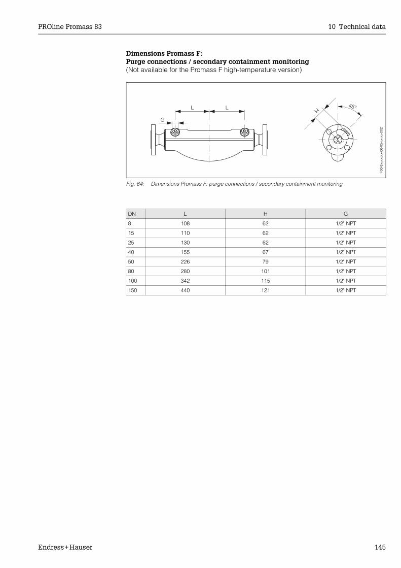
PROline Promass 83 10 Technical data
Endress+Hauser 145
Dimensions Promass F: Purge connections / secondary containment monitoring(Not available for the Promass F high-temperature version)
Fig. 64: Dimensions Promass F: purge connections / secondary containment monitoring
DN L H G
8 108 62 1/2" NPT
15 110 62 1/2" NPT
25 130 62 1/2" NPT
40 155 67 1/2" NPT
50 226 79 1/2" NPT
80 280 101 1/2" NPT
100 342 115 1/2" NPT
150 440 121 1/2" NPT
F06-
8xxx
xxxx
-06-
05-x
x-xx
-002

10 Technical data PROline Promass 83
146 Endress+Hauser
10.10 Dimensions: Promass M
Dimensions Promass M: flange connections EN (DIN), ANSI, JIS
Fig. 65: Dimensions Promass M: flange connections EN (DIN), ANSI, JIS
Flange EN 1092-1 (DIN 2501) / PN 16: PVDF
DN A B C G L N S LK U di
8 301 266 35 95 370 4 x Ø14 16 65 16.1 5.53
15 305 268 37 95 404 4 x Ø14 16 65 16.1 8.55
25 312 272 40 115 440 4 x Ø14 18 85 28.5 11.38
40 332 283 49 150 550 4 x Ø18 18 110 43.1 17.07
50 351 293 58 165 715 4 x Ø18 20 125 54.5 25.60
Flange EN 1092-1 (DIN 2501 / DIN 2512N 1)) / PN 40: 1.4404/316L, titaniumSurface roughness (flange): EN 1092-1 Form B1 (DIN 2526 Form C), Ra 6.3...12.5 µm
DN A B C G L N S LK U di
8 301 266 35 95 370 4 x Ø14 16 65 17.3 5.53
15 305 268 37 95 404 4 x Ø14 16 65 17.3 8.55
25 312 272 40 115 440 4 x Ø14 18 85 28.5 11.38
40 332 283 49 150 550 4 x Ø18 18 110 43.1 17.07
50 351 293 58 165 715 4 x Ø18 20 125 54.5 25.60
80 385 309 76 200 840 8 x Ø18 24 160 82.5 38.461) Flange with groove to EN 1092-1 Form D (DIN 2512N) available
Flange EN 1092-1 (DIN 2501) / PN 40 (with DN 25 flanges): 1.4404/316LSurface roughness (flange): EN 1092-1 Form B1 (DIN 2526 Form C), Ra 6.3...12.5 µm
DN A B C G L N S LK U di
8 301 266 35 115 440 4 x Ø14 18 85 28.5 5.53
15 305 268 37 115 440 4 x Ø14 18 85 28.5 8.55
F06-
83M
xxxx
x-06
-00-
xx-x
x-00
2
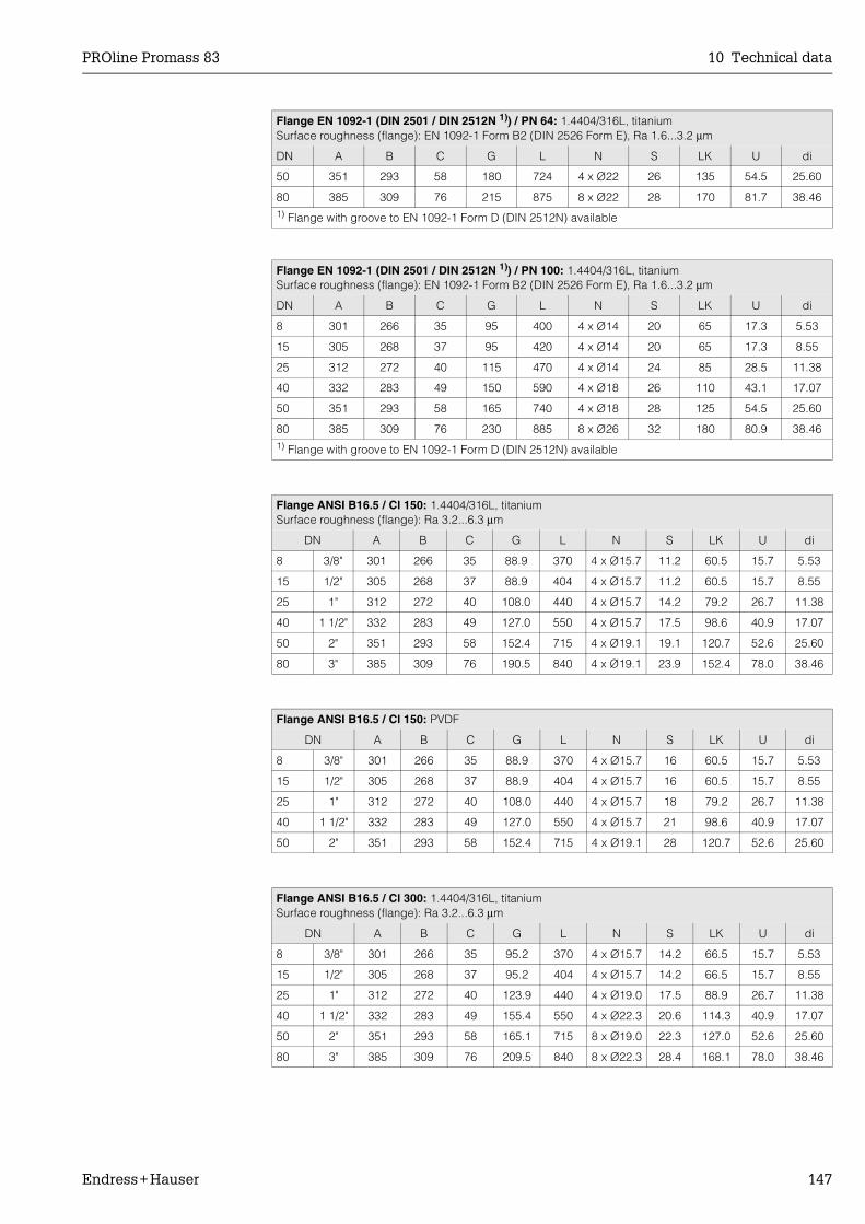
PROline Promass 83 10 Technical data
Endress+Hauser 147
Flange EN 1092-1 (DIN 2501 / DIN 2512N 1)) / PN 64: 1.4404/316L, titaniumSurface roughness (flange): EN 1092-1 Form B2 (DIN 2526 Form E), Ra 1.6...3.2 µm
DN A B C G L N S LK U di
50 351 293 58 180 724 4 x Ø22 26 135 54.5 25.60
80 385 309 76 215 875 8 x Ø22 28 170 81.7 38.461) Flange with groove to EN 1092-1 Form D (DIN 2512N) available
Flange EN 1092-1 (DIN 2501 / DIN 2512N 1)) / PN 100: 1.4404/316L, titaniumSurface roughness (flange): EN 1092-1 Form B2 (DIN 2526 Form E), Ra 1.6...3.2 µm
DN A B C G L N S LK U di
8 301 266 35 95 400 4 x Ø14 20 65 17.3 5.53
15 305 268 37 95 420 4 x Ø14 20 65 17.3 8.55
25 312 272 40 115 470 4 x Ø14 24 85 28.5 11.38
40 332 283 49 150 590 4 x Ø18 26 110 43.1 17.07
50 351 293 58 165 740 4 x Ø18 28 125 54.5 25.60
80 385 309 76 230 885 8 x Ø26 32 180 80.9 38.461) Flange with groove to EN 1092-1 Form D (DIN 2512N) available
Flange ANSI B16.5 / Cl 150: 1.4404/316L, titaniumSurface roughness (flange): Ra 3.2...6.3 µm
DN A B C G L N S LK U di
8 3/8" 301 266 35 88.9 370 4 x Ø15.7 11.2 60.5 15.7 5.53
15 1/2" 305 268 37 88.9 404 4 x Ø15.7 11.2 60.5 15.7 8.55
25 1" 312 272 40 108.0 440 4 x Ø15.7 14.2 79.2 26.7 11.38
40 1 1/2" 332 283 49 127.0 550 4 x Ø15.7 17.5 98.6 40.9 17.07
50 2" 351 293 58 152.4 715 4 x Ø19.1 19.1 120.7 52.6 25.60
80 3" 385 309 76 190.5 840 4 x Ø19.1 23.9 152.4 78.0 38.46
Flange ANSI B16.5 / Cl 150: PVDF
DN A B C G L N S LK U di
8 3/8" 301 266 35 88.9 370 4 x Ø15.7 16 60.5 15.7 5.53
15 1/2" 305 268 37 88.9 404 4 x Ø15.7 16 60.5 15.7 8.55
25 1" 312 272 40 108.0 440 4 x Ø15.7 18 79.2 26.7 11.38
40 1 1/2" 332 283 49 127.0 550 4 x Ø15.7 21 98.6 40.9 17.07
50 2" 351 293 58 152.4 715 4 x Ø19.1 28 120.7 52.6 25.60
Flange ANSI B16.5 / Cl 300: 1.4404/316L, titaniumSurface roughness (flange): Ra 3.2...6.3 µm
DN A B C G L N S LK U di
8 3/8" 301 266 35 95.2 370 4 x Ø15.7 14.2 66.5 15.7 5.53
15 1/2" 305 268 37 95.2 404 4 x Ø15.7 14.2 66.5 15.7 8.55
25 1" 312 272 40 123.9 440 4 x Ø19.0 17.5 88.9 26.7 11.38
40 1 1/2" 332 283 49 155.4 550 4 x Ø22.3 20.6 114.3 40.9 17.07
50 2" 351 293 58 165.1 715 8 x Ø19.0 22.3 127.0 52.6 25.60
80 3" 385 309 76 209.5 840 8 x Ø22.3 28.4 168.1 78.0 38.46

10 Technical data PROline Promass 83
148 Endress+Hauser
Flange ANSI B16.5 / Cl 600: 1.4404/316L, titaniumSurface roughness (flange): Ra 3.2...6.3 µm
DN A B C G L N S LK U di
8 3/8" 301 266 35 95.3 400 4 x Ø15.7 20.6 66.5 13.8 5.53
15 1/2" 305 268 37 95.3 420 4 x Ø15.7 20.6 66.5 13.8 8.55
25 1" 312 272 40 124.0 490 4 x Ø19.1 23.6 88.9 24.4 11.38
40 1 1/2" 332 283 49 155.4 600 4 x Ø22.4 28.7 114.3 38.1 17.07
50 2" 351 293 58 165.1 742 8 x Ø19.1 31.8 127.0 49.3 25.60
80 3" 385 309 76 209.6 900 8 x Ø22.4 38.2 168.1 73.7 38.46
Flange JIS B2238 / 10K: 1.4404/316L, titaniumSurface roughness (flange): Ra 3.2...6.3 µm
DN A B C G L N S LK U di
50 351 293 49.25 155 715 4 x Ø19 16 120 50 25.60
80 385 309 58 185 832 8 x Ø19 18 150 80 38.46
Flange JIS B2238 / 10K: PVDF
DN A B C G L N S LK U di
8 301 266 35 95 370 4 x Ø15 16 70 15 5.53
15 305 268 37 95 404 4 x Ø15 16 70 15 8.55
25 312 272 40 125 440 4 x Ø19 18 90 25 11.38
40 332 283 49 140 550 4 x Ø19 21 105 40 17.07
50 351 293 58 155 715 4 x Ø19 22 120 50 25.60
Flange JIS B2238 / 20K: 1.4404/316L, titaniumSurface roughness (flange): Ra 3.2...6.3 µm
DN A B C G L N S LK U di
8 301 266 35 95 370 4 x Ø15 14 70 15 5.53
15 305 268 37 95 404 4 x Ø15 14 70 15 8.55
25 312 272 40 125 440 4 x Ø19 16 90 25 11.38
40 332 283 49 140 550 4 x Ø19 18 105 40 17.07
50 351 293 58 155 715 8 x Ø19 18 120 50 25.60
80 385 309 76 200 832 8 x Ø23 22 160 80 38.46
Flange JIS B2238 / 40K: 1.4404/316L, titaniumSurface roughness (flange): Ra 3.2...6.3 µm
DN A B C G L N S LK U di
8 301 266 35 115 400 4 x Ø19 20 80 15 5.53
15 305 268 37 115 425 4 x Ø19 20 80 15 8.55
25 312 272 40 130 485 4 x Ø19 22 95 25 11.38
40 332 283 49 160 600 4 x Ø23 24 120 38 17.07
50 351 293 58 165 760 8 x Ø19 26 130 50 25.60
80 385 309 76 210 890 8 x Ø23 32 170 75 38.46
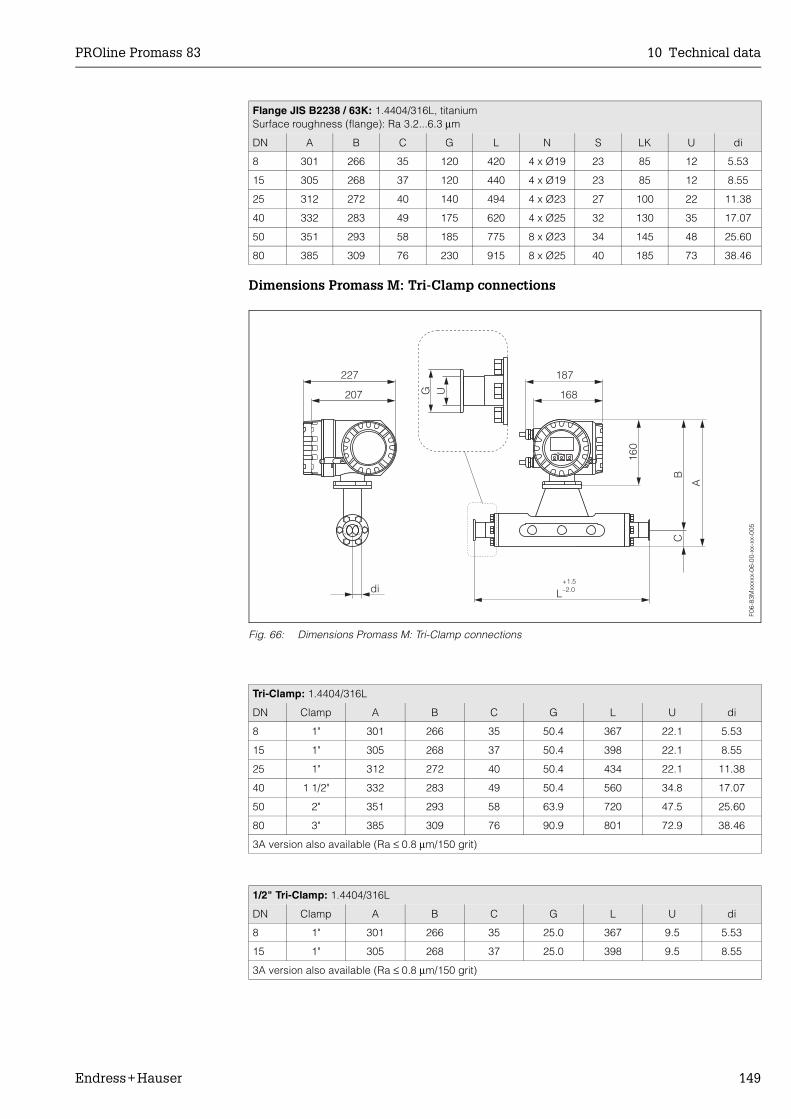
PROline Promass 83 10 Technical data
Endress+Hauser 149
Dimensions Promass M: Tri-Clamp connections
Fig. 66: Dimensions Promass M: Tri-Clamp connections
Flange JIS B2238 / 63K: 1.4404/316L, titaniumSurface roughness (flange): Ra 3.2...6.3 µm
DN A B C G L N S LK U di
8 301 266 35 120 420 4 x Ø19 23 85 12 5.53
15 305 268 37 120 440 4 x Ø19 23 85 12 8.55
25 312 272 40 140 494 4 x Ø23 27 100 22 11.38
40 332 283 49 175 620 4 x Ø25 32 130 35 17.07
50 351 293 58 185 775 8 x Ø23 34 145 48 25.60
80 385 309 76 230 915 8 x Ø25 40 185 73 38.46
Tri-Clamp: 1.4404/316L
DN Clamp A B C G L U di
8 1" 301 266 35 50.4 367 22.1 5.53
15 1" 305 268 37 50.4 398 22.1 8.55
25 1" 312 272 40 50.4 434 22.1 11.38
40 1 1/2" 332 283 49 50.4 560 34.8 17.07
50 2" 351 293 58 63.9 720 47.5 25.60
80 3" 385 309 76 90.9 801 72.9 38.46
3A version also available (Ra ≤ 0.8 µm/150 grit)
1/2" Tri-Clamp: 1.4404/316L
DN Clamp A B C G L U di
8 1" 301 266 35 25.0 367 9.5 5.53
15 1" 305 268 37 25.0 398 9.5 8.55
3A version also available (Ra ≤ 0.8 µm/150 grit)
F06-
83M
xxxx
x-06
-00-
xx-x
x-00
5

10 Technical data PROline Promass 83
150 Endress+Hauser
Dimensions Promass M: DIN 11851 connections (hygienic coupling)
Fig. 67: Dimensions Promass M: DIN 11851 connections (hygienic coupling)
Hygienic coupling DIN 11851: 1.4404/316L
DN A B C G L U di
8 301 266 35 Rd 34 x 1/8" 367 16 5.53
15 305 268 37 Rd 34 x 1/8" 398 16 8.55
25 312 272 40 Rd 52 x 1/6" 434 26 11.38
40 332 283 49 Rd 65 x 1/6" 560 38 17.07
50 351 293 58 Rd 78 x 1/6" 720 50 25.60
80 385 309 76 Rd 110 x 1/4" 815 81 38.46
3A version also available (Ra ≤ 0.8 µm/150 grit)
F06-
83M
xxxx
x-06
-00-
xx-x
x-00
3

PROline Promass 83 10 Technical data
Endress+Hauser 151
Dimensions Promass M: DIN 11864-1 Form A connections (couplings)
Fig. 68: Dimensions Promass M: DIN 11864-1 Form A connections (couplings)
Coupling DIN 11864-1 Form A: 1.4404/316L
DN A B C G L U di
8 301 266 35 Rd 28x 1/8" 367 10 5.53
15 305 268 37 Rd 34 x 1/8" 398 16 8.55
25 312 272 40 Rd 52 x 1/6" 434 26 11.38
40 332 283 49 Rd 65 x 1/6" 560 38 17.07
50 351 293 58 Rd 78 x 1/6" 720 50 25.60
80 385 309 76 Rd 110 x 1/4" 815 81 38.46
3A version also available (Ra ≤ 0.8 µm/150 grit)
F06-
83M
xxxx
x-06
-00-
xx-x
x-00
6
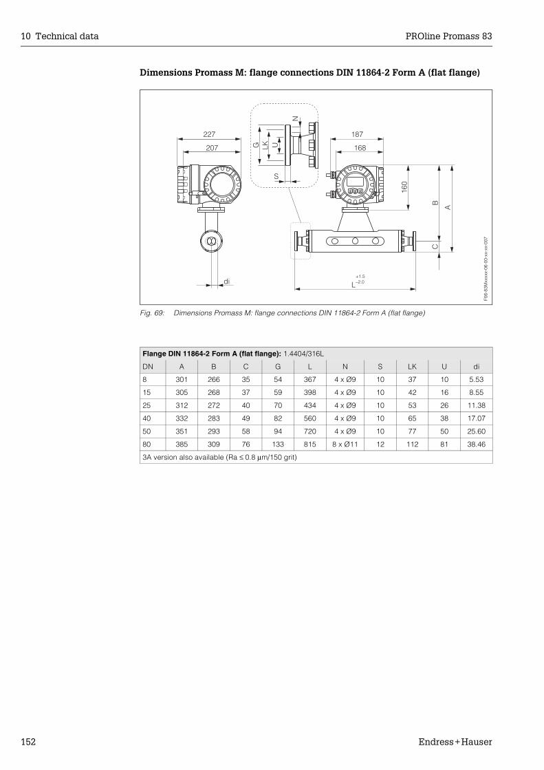
10 Technical data PROline Promass 83
152 Endress+Hauser
Dimensions Promass M: flange connections DIN 11864-2 Form A (flat flange)
Fig. 69: Dimensions Promass M: flange connections DIN 11864-2 Form A (flat flange)
Flange DIN 11864-2 Form A (flat flange): 1.4404/316L
DN A B C G L N S LK U di
8 301 266 35 54 367 4 x Ø9 10 37 10 5.53
15 305 268 37 59 398 4 x Ø9 10 42 16 8.55
25 312 272 40 70 434 4 x Ø9 10 53 26 11.38
40 332 283 49 82 560 4 x Ø9 10 65 38 17.07
50 351 293 58 94 720 4 x Ø9 10 77 50 25.60
80 385 309 76 133 815 8 x Ø11 12 112 81 38.46
3A version also available (Ra ≤ 0.8 µm/150 grit)
F06-
83M
xxxx
x-06
-00-
xx-x
x-00
7

PROline Promass 83 10 Technical data
Endress+Hauser 153
Dimensions Promass M: ISO 2853 connections (couplings)
Fig. 70: Dimensions Promass M: ISO 2853 connections (couplings)
Coupling ISO 2853: 1.4404/316L
DN A B C G 1) L U di
8 301 266 35 37.13 367 22.6 5.53
15 305 268 37 37.13 398 22.6 8.55
25 312 272 40 37.13 434 22.6 11.38
40 332 283 49 52.68 560 35.6 17.07
50 351 293 58 64.16 720 48.6 25.60
80 385 309 76 91.19 815 72.9 38.461) Max. thread diameter to ISO 2853 Annex A3A version also available (Ra ≤ 0.8 µm/150 grit)
F06-
83M
xxxx
x-06
-00-
xx-x
x-00
8

10 Technical data PROline Promass 83
154 Endress+Hauser
Dimensions Promass M: SMS 1145 connections (hygienic coupling)
Fig. 71: Dimensions Promass M: SMS 1145 connections (hygienic coupling)
Hygienic coupling SMS 1145: 1.4404/316L
DN A B C G L U di
8 301 266 35 Rd 40 x 1/6" 367 22.5 5.53
15 305 268 37 Rd 40 x 1/6" 398 22.5 8.55
25 312 272 40 Rd 40 x 1/6" 434 22.5 11.38
40 332 283 49 Rd 40 x 1/6" 560 35.5 17.07
50 351 293 58 Rd 70 x 1/6" 720 48.5 25.60
80 385 309 76 Rd 98 x 1/6" 792 72.0 38.46
3A version also available (Ra ≤ 0.8 µm/150 grit)
F06-
83M
xxxx
x-06
-00-
xx-x
x-00
4
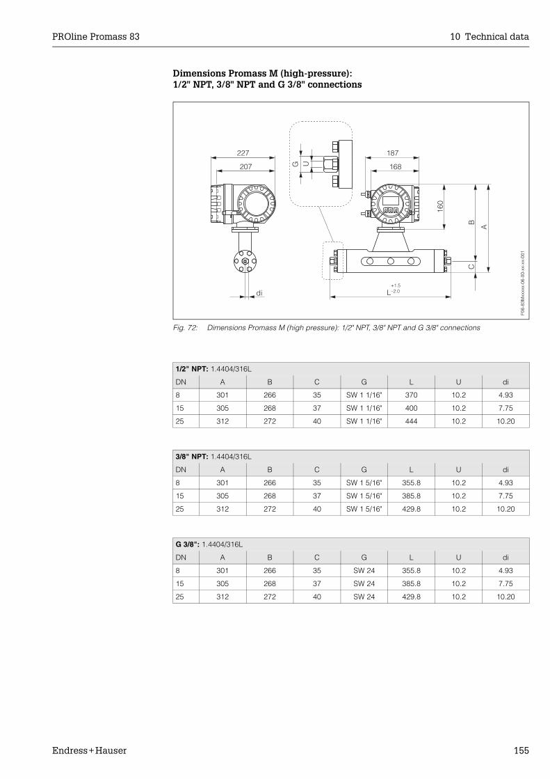
PROline Promass 83 10 Technical data
Endress+Hauser 155
Dimensions Promass M (high-pressure):1/2" NPT, 3/8" NPT and G 3/8" connections
Fig. 72: Dimensions Promass M (high pressure): 1/2" NPT, 3/8" NPT and G 3/8" connections
1/2" NPT: 1.4404/316L
DN A B C G L U di
8 301 266 35 SW 1 1/16" 370 10.2 4.93
15 305 268 37 SW 1 1/16" 400 10.2 7.75
25 312 272 40 SW 1 1/16" 444 10.2 10.20
3/8" NPT: 1.4404/316L
DN A B C G L U di
8 301 266 35 SW 1 5/16" 355.8 10.2 4.93
15 305 268 37 SW 1 5/16" 385.8 10.2 7.75
25 312 272 40 SW 1 5/16" 429.8 10.2 10.20
G 3/8": 1.4404/316L
DN A B C G L U di
8 301 266 35 SW 24 355.8 10.2 4.93
15 305 268 37 SW 24 385.8 10.2 7.75
25 312 272 40 SW 24 429.8 10.2 10.20
F06-
83M
xxxx
x-06
-00-
xx-x
x-00
1
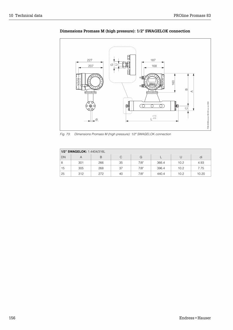
10 Technical data PROline Promass 83
156 Endress+Hauser
Dimensions Promass M (high pressure): 1/2" SWAGELOK connection
Fig. 73: Dimensions Promass M (high pressure): 1/2" SWAGELOK connection
1/2" SWAGELOK: 1.4404/316L
DN A B C G L U di
8 301 266 35 7/8" 366.4 10.2 4.93
15 305 268 37 7/8" 396.4 10.2 7.75
25 312 272 40 7/8" 440.4 10.2 10.20
F06-
83M
xxxx
x-06
-00-
xx-x
x-00
0
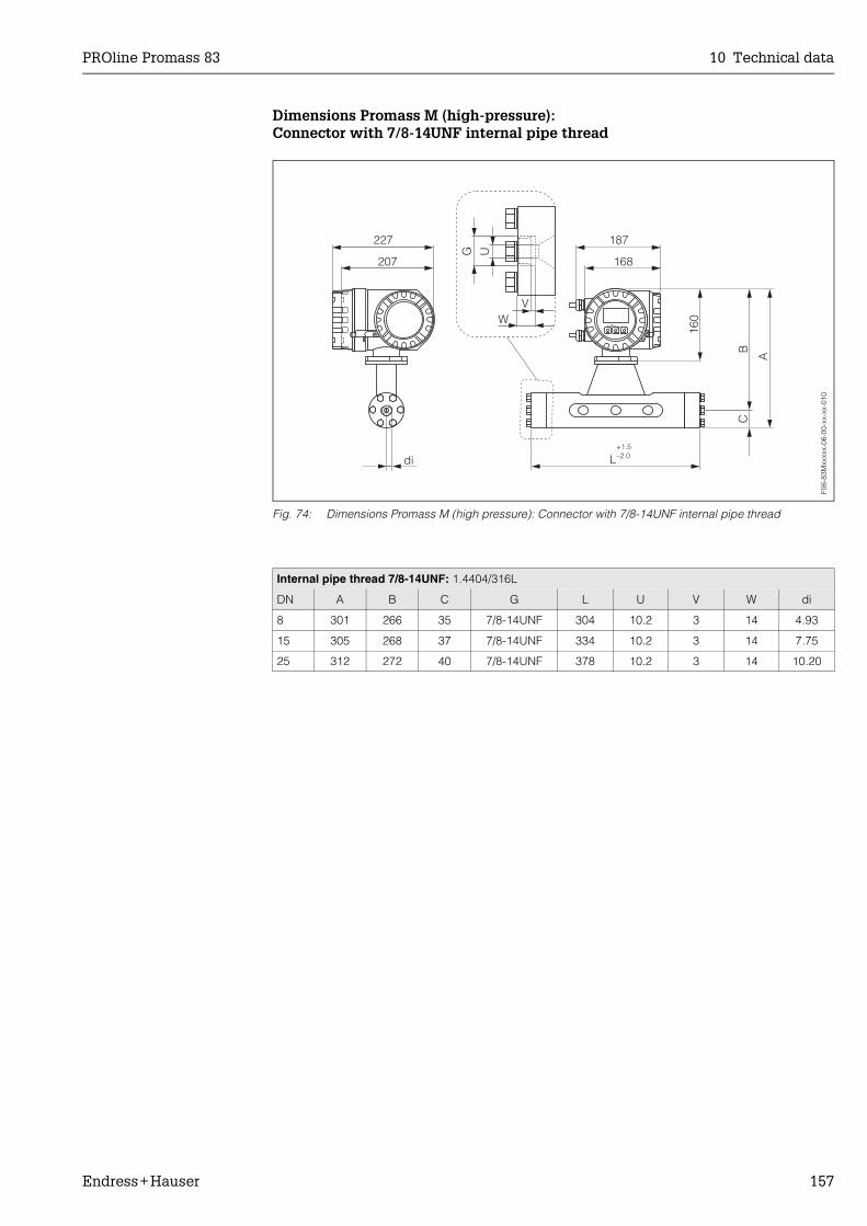
PROline Promass 83 10 Technical data
Endress+Hauser 157
Dimensions Promass M (high-pressure):Connector with 7/8-14UNF internal pipe thread
Fig. 74: Dimensions Promass M (high pressure): Connector with 7/8-14UNF internal pipe thread
Internal pipe thread 7/8-14UNF: 1.4404/316L
DN A B C G L U V W di
8 301 266 35 7/8-14UNF 304 10.2 3 14 4.93
15 305 268 37 7/8-14UNF 334 10.2 3 14 7.75
25 312 272 40 7/8-14UNF 378 10.2 3 14 10.20
F06-
83M
xxxx
x-06
-00-
xx-x
x-01
0

10 Technical data PROline Promass 83
158 Endress+Hauser
Dimensions Promass M: without process connections
Fig. 75: Dimensions Promass M: without process connections
DN L J K M bmax. bmin.
8 256 27 54 6 x M 8 12 10
8 1) 256 27 54 6 x M 8 12 10
15 286 35 56 6 x M 8 12 10
15 1) 286 35 56 6 x M 8 12 10
25 310 40 62 6 x M 8 12 10
25 1) 310 40 62 6 x M 8 12 10
40 410 53 80 8 x M 10 15 13
50 544 73 94 8 x M 10 15 13
80 644 102 128 12 x M 12 18 151) High pressure version; permissible thread: A4 - 80; lubricant: Molykote P37
Tightening torque Lubricated thread O-ring
DN Nm yes/no Thickness Inside Ø
8 30.0 no 2.62 21.89
8 1) 19.3 yes 2.62 21.89
15 30.0 no 2.62 29.82
15 1) 19.3 yes 2.62 29.82
25 30.0 no 2.62 34.60
25 1) 19.3 yes 2.62 34.60
40 60.0 no 2.62 47.30
50 60.0 yes 2.62 67.95
80 100.0 yes 3.53 94.841) High pressure version; permissible thread: A4 - 80; lubricant: Molykote P37
F06-
8xxx
xxxx
-06-
05-x
x-xx
-001

PROline Promass 83 10 Technical data
Endress+Hauser 159
Dimensions Promass M:Purge connections / secondary containment monitoring
Fig. 76: Dimensions Promass M: purge connections / secondary containment monitoring
DN L H G
8 85 44.0 1/2" NPT
15 100 46.5 1/2" NPT
25 110 50.0 1/2" NPT
40 155 59.0 1/2" NPT
50 210 67.5 1/2" NPT
80 210 81.5 1/2" NPT
F06-
8xxx
xxxx
-06-
05-x
x-xx
-003

10 Technical data PROline Promass 83
160 Endress+Hauser
10.11 Dimensions: Promass E
Dimensions Promass E: flange connections EN (DIN), ANSI, JIS
Abb. 77: Dimensions Promass E: flange connections EN (DIN), ANSI, JIS
Flange EN 1092-1 (DIN 2501 / DIN 2512N 1)) / PN 40: 1.4404/316L
DN A B C G L N S LK U di
8 317 224 93 95 232 4 x Ø14 16 65 17.3 5.35
15 331 226 105 95 279 4 x Ø14 16 65 17.3 8.30
25 337 231 106 115 329 4 x Ø14 18 85 28.5 12.00
40 358 237 121 150 445 4 x Ø18 18 110 43.1 17.60
50 423 253 170 165 556 4 x Ø18 20 125 54.5 26.001) Flange with groove to EN 1092-1 Form D (DIN 2512N) available
Flange EN 1092-1 (DIN 2501) / PN 40 (with DN 25-Flanges): 1.4404/316L
DN A B C G L N S LK U di
8 341 266 75 115 440 4 x Ø14 18 85 28.5 5.35
15 341 266 75 115 440 4 x Ø14 18 85 28.5 8.30
Flange EN 1092-1 (DIN 2501 / DIN 2512N 1)) / PN 63: 1.4404/316L
DN A B C G L N S LK U di
50 423 253 170 180 565 4 x Ø22 26 135 54.5 26.001) Flange with groove to EN 1092-1 Form D (DIN 2512N) available
227 187
207
S
168
CB
160
A
LdiN
G LK U
+1.5–2.0+1.5–2.0
Esc
E- +
F06-
83E
xxxx
x-06
-00-
xx-x
x-00
0

PROline Promass 83 10 Technical data
Endress+Hauser 161
Flange EN 1092-1 (DIN 2501 / DIN 2512N 1)) / PN 100: 1.4404/316L
DN A B C G L N S LK U di
8 317 224 93 105 261 4 x Ø14 20 75 17.3 5.35
15 331 226 105 105 295 4 x Ø14 20 75 17.3 8.30
25 337 231 106 140 360 4 x Ø18 24 100 28.5 12.00
40 358 237 121 170 486 4 x Ø22 26 125 42.5 17.60
50 423 253 170 195 581 4 x Ø26 28 145 53.9 26.001) Flange with groove to EN 1092-1 Form D (DIN 2512N) available
Flange ANSI B16.5 / Cl 150: 1.4404/316L
DN A B C G L N S LK U di
8 3/8" 317 224 93 88.9 232 4 x Ø15.7 11.2 60.5 15.7 5.35
15 1/2" 331 226 105 88.9 279 4 x Ø15.7 11.2 60.5 15.7 8.30
25 1" 337 231 106 108.0 329 4 x Ø15.7 14.2 79.2 26.7 12.00
40 1 1/2" 358 237 121 127.0 445 4 x Ø15.7 17.5 98.6 40.9 17.60
50 2" 423 253 170 152.4 556 4 x Ø19.1 19.1 120.7 52.6 26.00
Flange ANSI B16.5 / Cl 300: 1.4404/316L
DN A B C G L N S LK U di
8 3/8" 317 224 93 95.2 232 4 x Ø15.7 14.2 66.5 15.7 5.35
15 1/2" 331 226 105 95.2 279 4 x Ø15.7 14.2 66.5 15.7 8.30
25 1" 337 231 106 123.9 329 4 x Ø19.0 17.5 88.9 26.7 12.00
40 1 1/2" 358 237 121 155.4 445 4 x Ø22.3 20.6 114.3 40.9 17.60
50 2" 423 253 170 165.1 556 8 x Ø19.0 22.3 127.0 52.6 26.00
Flange ANSI B16.5 / Cl 600: 1.4404/316L
DN A B C G L N S LK U di
8 3/8" 317 224 93 95.3 261 4 x Ø15.7 20.6 66.5 13.9 5.35
15 1/2" 331 226 105 95.3 295 4 x Ø15.7 20.6 66.5 13.9 8.30
25 1" 337 231 106 124.0 380 4 x Ø19.1 23.9 88.9 24.3 12.00
40 1 1/2" 358 237 121 155.4 496 4 x Ø22.4 28.7 114.3 38.1 17.60
50 2" 423 253 170 165.1 583 8 x Ø19.1 31.8 127.0 49.2 26.00
Flange JIS B2238 / 10K: 1.4404/316L
DN A B C G L N S LK U di
50 423 253 170 155 556 4 x Ø19 16 120 50 26.00
Flange JIS B2238 / 20K: 1.4404/316L
DN A B C G L N S LK U di
8 317 224 93 95 232 4 x Ø15 14 70 15 5.35
15 331 226 105 95 279 4 x Ø15 14 70 15 8.30
25 337 231 106 125 329 4 x Ø19 16 90 25 12.00
40 358 237 121 140 445 4 x Ø19 18 105 40 17.60
50 423 253 170 155 556 8 x Ø19 18 120 50 26.00
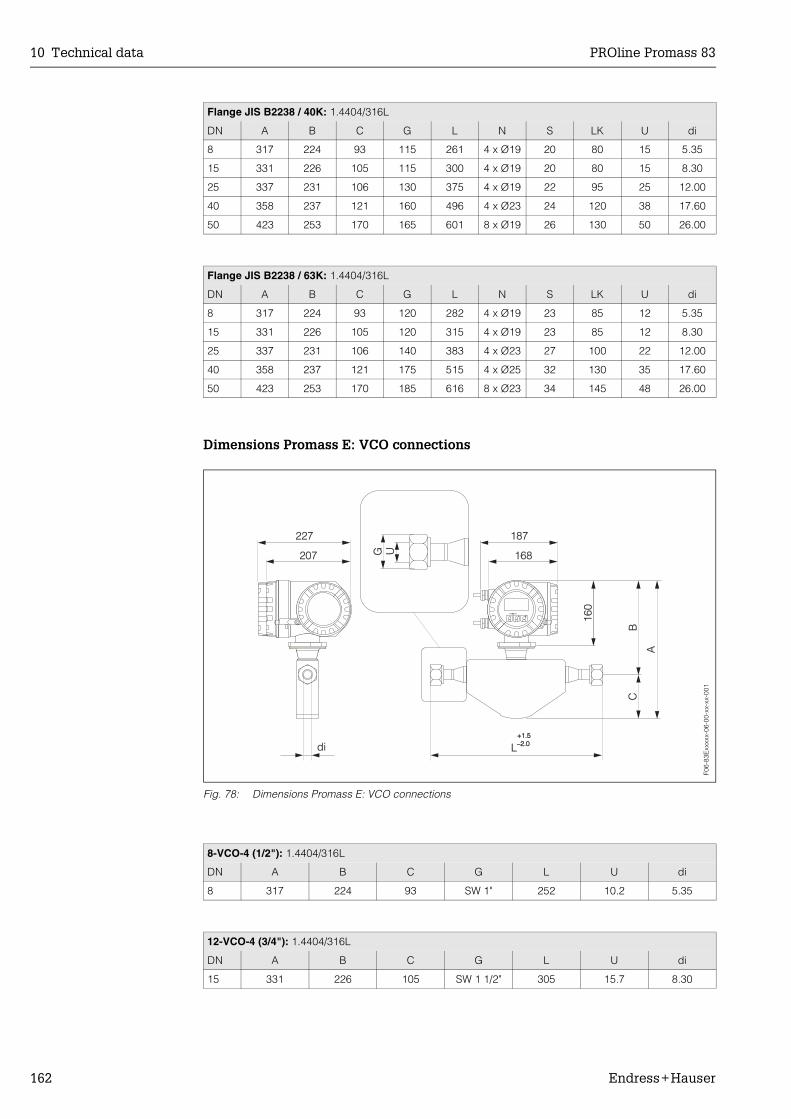
10 Technical data PROline Promass 83
162 Endress+Hauser
Dimensions Promass E: VCO connections
Fig. 78: Dimensions Promass E: VCO connections
Flange JIS B2238 / 40K: 1.4404/316L
DN A B C G L N S LK U di
8 317 224 93 115 261 4 x Ø19 20 80 15 5.35
15 331 226 105 115 300 4 x Ø19 20 80 15 8.30
25 337 231 106 130 375 4 x Ø19 22 95 25 12.00
40 358 237 121 160 496 4 x Ø23 24 120 38 17.60
50 423 253 170 165 601 8 x Ø19 26 130 50 26.00
Flange JIS B2238 / 63K: 1.4404/316L
DN A B C G L N S LK U di
8 317 224 93 120 282 4 x Ø19 23 85 12 5.35
15 331 226 105 120 315 4 x Ø19 23 85 12 8.30
25 337 231 106 140 383 4 x Ø23 27 100 22 12.00
40 358 237 121 175 515 4 x Ø25 32 130 35 17.60
50 423 253 170 185 616 8 x Ø23 34 145 48 26.00
8-VCO-4 (1/2"): 1.4404/316L
DN A B C G L U di
8 317 224 93 SW 1" 252 10.2 5.35
12-VCO-4 (3/4"): 1.4404/316L
DN A B C G L U di
15 331 226 105 SW 1 1/2" 305 15.7 8.30
227 187
207 168
CB
160
A
Ldi+1.5–2.0+1.5–2.0
G U
Esc
E- +
F06-
83E
xxxx
x-06
-00-
xx-x
x-00
1

PROline Promass 83 10 Technical data
Endress+Hauser 163
Dimensions Promass E: Tri-Clamp connections
Fig. 79: Dimensions Promass E: Tri-Clamp connections
Tri-Clamp: 1.4404/316L
DN Clamp A B C G L U di
8 1" 317 224 93 50.4 229 22.1 5.35
15 1" 331 226 105 50.4 273 22.1 8.30
25 1" 337 231 106 50.4 324 22.1 12.00
40 1 1/2" 358 237 121 50.4 456 34.8 17.60
50 2" 423 253 170 63.9 562 47.5 26.00
3A version also available (Ra ≤ 0.8 µm/150 grit)
1/2"-Tri-Clamp: 1.4404/316L
DN Clamp A B C G L U di
8 1/2" 317 224 93 25.0 229 9.5 5.35
15 1/2" 331 226 105 25.0 273 9.5 8.30
3A version also available (Ra ≤ 0.8 µm/150 grit)
227 187
207 168
CB
160
A
LdiG U
+1.5–2.0+1.5–2.0
Esc
E- +
F06-
83E
xxxx
x-06
-00-
xx-x
x-00
2

10 Technical data PROline Promass 83
164 Endress+Hauser
Dimensions Promass E: DIN 11851 connections (hygienic coupling)
Fig. 80: Dimensions Promass E: DIN 11851 connections (hygienic coupling)
Hygienic coupling DIN 11851: 1.4404/316L
DN A B C G L U di
8 317 224 93 Rd 34 x 1/8" 229 16 5.35
15 331 226 105 Rd 34 x 1/8" 273 16 8.30
25 337 231 106 Rd 52 x 1/6" 324 26 12.00
40 358 237 121 Rd 65 x 1/6" 456 38 17.60
50 423 253 170 Rd 78 x 1/6" 562 50 26.00
3A version also available (Ra ≤ 0.8 µm/150 grit)
227 187
207 168
CB
160
A
Ldi
G U+1.5–2.0+1.5–2.0
Esc
E- +
F06-
83E
xxxx
x-06
-00-
xx-x
x-00
3

PROline Promass 83 10 Technical data
Endress+Hauser 165
Dimensions Promass E: DIN 11864-1 Form A connections (couplings)
Fig. 81: Dimensions Promass E: DIN 11864-1 Form A connections (couplings)
Coupling DIN 11864-1 Form A: 1.4404/316L
DN A B C G L U di
8 317 224 93 Rd 28 x 1/8" 229 10 5.35
15 331 226 105 Rd 34 x 1/8" 273 16 8.30
25 337 231 106 Rd 52 x 1/6" 324 26 12.00
40 358 237 121 Rd 65 x 1/6" 456 38 17.60
50 423 253 170 Rd 78 x 1/6" 562 50 26.00
3A version also available (Ra ≤ 0.8 µm/150 grit)
227 187
207 168
CB
160
A
LdiG U
+1.5–2.0+1.5–2.0
Esc
E- +
F06-
83E
xxxx
x-06
-00-
xx-x
x-00
4
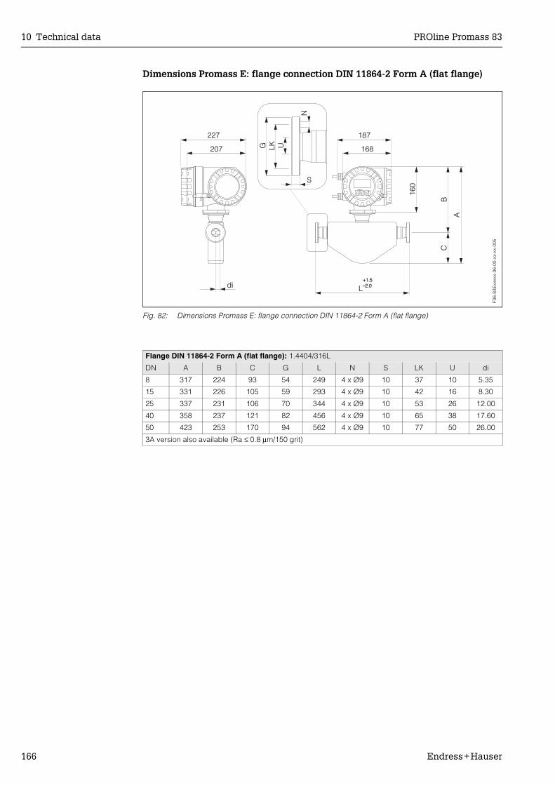
10 Technical data PROline Promass 83
166 Endress+Hauser
Dimensions Promass E: flange connection DIN 11864-2 Form A (flat flange)
Fig. 82: Dimensions Promass E: flange connection DIN 11864-2 Form A (flat flange)
Flange DIN 11864-2 Form A (flat flange): 1.4404/316L
DN A B C G L N S LK U di
8 317 224 93 54 249 4 x Ø9 10 37 10 5.35
15 331 226 105 59 293 4 x Ø9 10 42 16 8.30
25 337 231 106 70 344 4 x Ø9 10 53 26 12.00
40 358 237 121 82 456 4 x Ø9 10 65 38 17.60
50 423 253 170 94 562 4 x Ø9 10 77 50 26.00
3A version also available (Ra ≤ 0.8 µm/150 grit)
227 187
207 168
CB
160
A
Ldi+1.5–2.0+1.5–2.0
G
N
S
LK U
Esc
E- +
F06-
83E
xxxx
x-06
-00-
xx-x
x-00
5

PROline Promass 83 10 Technical data
Endress+Hauser 167
Dimensions Promass E: ISO 2853 connection (couplings)
Fig. 83: Dimensions Promass E: ISO 2853 connection (couplings)
Coupling ISO 2853: 1.4404/316L
DN A B C G 1) L U di
8 317 224 93 37.13 229 22.6 5.35
15 331 226 105 37.13 273 22.6 8.30
25 337 231 106 37.13 324 22.6 12.00
40 358 237 121 52.68 456 35.6 17.60
50 423 253 170 64.16 562 48.6 26.001) Max. thread diameter to ISO 2853 Annex A, 3A version also available (Ra ≤ 0.8 µm/150 grit)
227 187
207 168
CB
160
A
LdiG U
+1.5–2.0+1.5–2.0
Esc
E- +
F06-
83E
xxxx
x-06
-00-
xx-x
x-00
6

10 Technical data PROline Promass 83
168 Endress+Hauser
Dimensions Promass E: SMS 1145 connection (hygienic coupling)
Fig. 84: Dimensions Promass E: SMS 1145 connection (hygienic coupling)
Hygienic coupling SMS 1145: 1.4404/316L
DN A B C G L U di
8 317 224 93 Rd 40 x 1/6" 229 22.5 5.35
15 331 226 105 Rd 40 x 1/6" 273 22.5 8.30
25 337 231 106 Rd 40 x 1/6" 324 22.5 12.00
40 358 237 121 Rd 60 x 1/6" 456 35.5 17.60
50 423 253 170 Rd 70 x 1/6" 562 48.5 26.00
3A version also available (Ra ≤ 0.8 µm/150 grit)
227 187
207 168
CB
160
A
Ldi
G U+1.5–2.0+1.5–2.0
Esc
E- +
F06-
83E
xxxx
x-06
-00-
xx-x
x-00
7

PROline Promass 83 10 Technical data
Endress+Hauser 169
10.12 Dimensions: Promass A
Dimensions Promass A: 4-VCO-4 connection (welded)
Fig. 85: Dimensions Promass A: 4-VCO-4 connection (welded)
4-VCO-4 connection: 1.4539/904L, Alloy C-22
DN A B C E F G K L M P U / di
1 1) 305 273 32 228 160 SW 11/16" 145 290 165 120 1.1
2 1) 305 273 32 310 160 SW 11/16" 145 372 165 120 1.8
2 2) 305 273 32 310 160 SW 11/16" 145 372 165 120 1.4
4 1) 315 283 32 435 220 SW 11/16" 175 497 195 150 3.5
4 2) 315 283 32 435 220 SW 11/16" 175 497 195 150 3.01) 3A version also available (Ra ≤ 0.4 µm/240 grit). For 1.4539/904L only2) High pressure version
F06-
83A
xxxx
x-06
-00-
xx-x
x-00
0
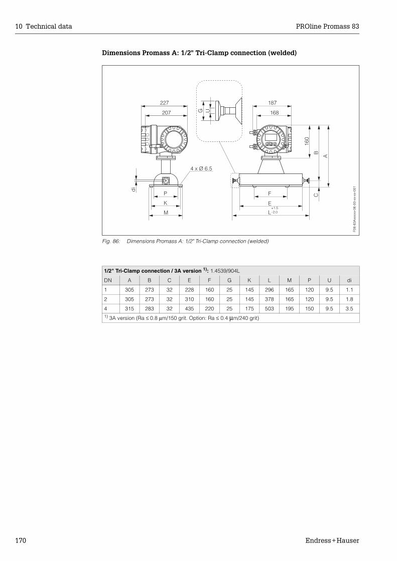
10 Technical data PROline Promass 83
170 Endress+Hauser
Dimensions Promass A: 1/2" Tri-Clamp connection (welded)
Fig. 86: Dimensions Promass A: 1/2" Tri-Clamp connection (welded)
1/2" Tri-Clamp connection / 3A version 1): 1.4539/904L
DN A B C E F G K L M P U di
1 305 273 32 228 160 25 145 296 165 120 9.5 1.1
2 305 273 32 310 160 25 145 378 165 120 9.5 1.8
4 315 283 32 435 220 25 175 503 195 150 9.5 3.51) 3A version (Ra ≤ 0.8 µm/150 grit. Option: Ra ≤ 0.4 µm/240 grit)
F06-
83A
xxxx
x-06
-00-
xx-x
x-00
1
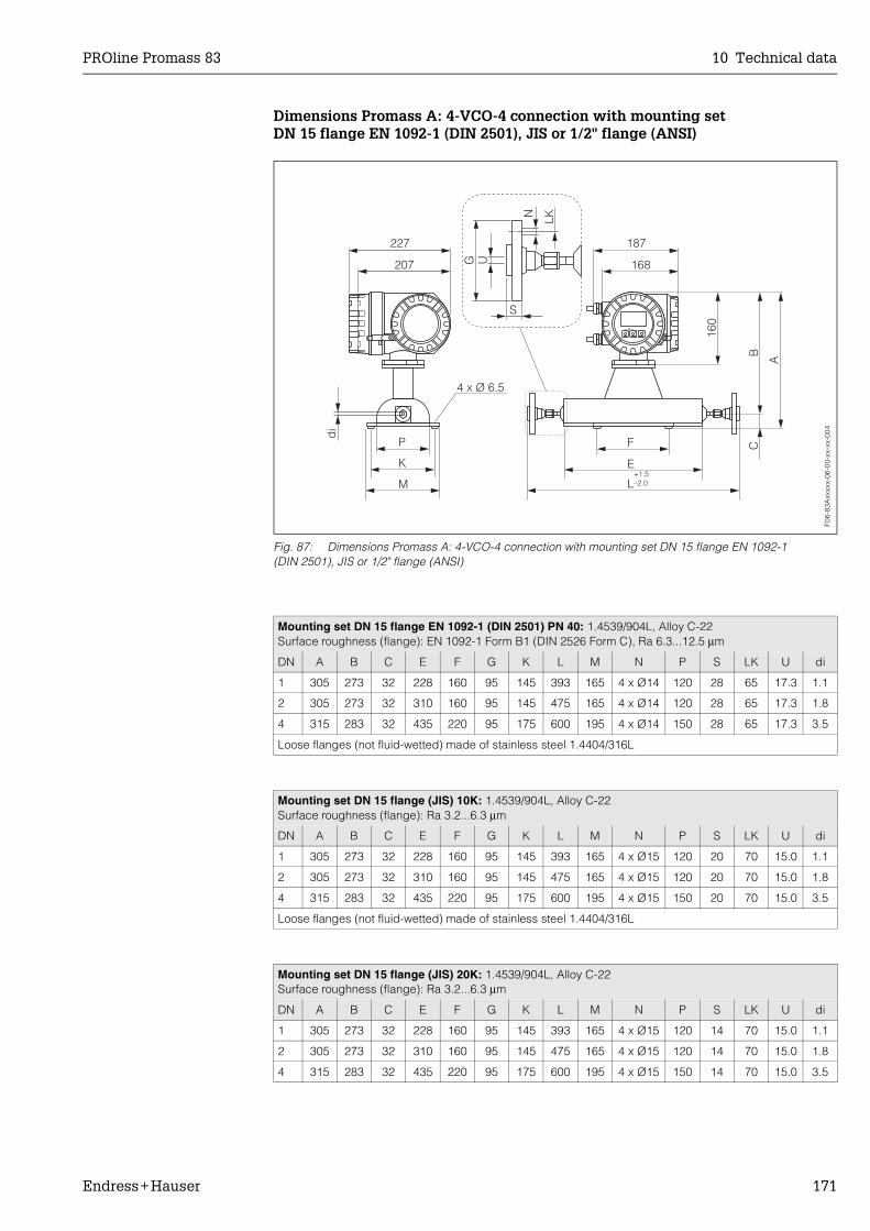
PROline Promass 83 10 Technical data
Endress+Hauser 171
Dimensions Promass A: 4-VCO-4 connection with mounting setDN 15 flange EN 1092-1 (DIN 2501), JIS or 1/2" flange (ANSI)
Fig. 87: Dimensions Promass A: 4-VCO-4 connection with mounting set DN 15 flange EN 1092-1 (DIN 2501), JIS or 1/2" flange (ANSI)
Mounting set DN 15 flange EN 1092-1 (DIN 2501) PN 40: 1.4539/904L, Alloy C-22Surface roughness (flange): EN 1092-1 Form B1 (DIN 2526 Form C), Ra 6.3...12.5 µm
DN A B C E F G K L M N P S LK U di
1 305 273 32 228 160 95 145 393 165 4 x Ø14 120 28 65 17.3 1.1
2 305 273 32 310 160 95 145 475 165 4 x Ø14 120 28 65 17.3 1.8
4 315 283 32 435 220 95 175 600 195 4 x Ø14 150 28 65 17.3 3.5
Loose flanges (not fluid-wetted) made of stainless steel 1.4404/316L
Mounting set DN 15 flange (JIS) 10K: 1.4539/904L, Alloy C-22Surface roughness (flange): Ra 3.2...6.3 µm
DN A B C E F G K L M N P S LK U di
1 305 273 32 228 160 95 145 393 165 4 x Ø15 120 20 70 15.0 1.1
2 305 273 32 310 160 95 145 475 165 4 x Ø15 120 20 70 15.0 1.8
4 315 283 32 435 220 95 175 600 195 4 x Ø15 150 20 70 15.0 3.5
Loose flanges (not fluid-wetted) made of stainless steel 1.4404/316L
Mounting set DN 15 flange (JIS) 20K: 1.4539/904L, Alloy C-22Surface roughness (flange): Ra 3.2...6.3 µm
DN A B C E F G K L M N P S LK U di
1 305 273 32 228 160 95 145 393 165 4 x Ø15 120 14 70 15.0 1.1
2 305 273 32 310 160 95 145 475 165 4 x Ø15 120 14 70 15.0 1.8
4 315 283 32 435 220 95 175 600 195 4 x Ø15 150 14 70 15.0 3.5
F06-
83A
xxxx
x-06
-00-
xx-x
x-00
4

10 Technical data PROline Promass 83
172 Endress+Hauser
Dimensions Promass A: 4-VCO-4 connection with mounting set 1/4" NPT-F
Fig. 88: Dimensions Promass A: 4-VCO-4 connection with mounting set 1/4" NPT-F
Mounting set 1/2" flange (ANSI) Cl 150: 1.4539/904L, Alloy C-22Surface roughness (flange): Ra 3.2...6.3 µm
DN A B C E F G K L M N P S LK U di
1 1/24" 305 273 32 228 160 88.9 145 393 165 4 x Ø15.7 120 17.7 60.5 15.7 1.1
2 1/12" 305 273 32 310 160 88.9 145 475 165 4 x Ø15.7 120 17.7 60.5 15.7 1.8
4 1/8" 315 283 32 435 220 88.9 175 600 195 4 x Ø15.7 150 17.7 60.5 15.7 3.5
Loose flanges (not fluid-wetted) made of stainless steel 1.4404/316L
Mounting set 1/2" flange (ANSI) Cl 300: 1.4539/904L, Alloy C-22Surface roughness (flange): Ra 3.2...6.3 µm
DN A B C E F G K L M N P S LK U di
1 1/24" 305 273 32 228 160 95.2 145 393 165 4 x Ø15.7 120 20.7 66.5 15.7 1.1
2 1/12" 305 273 32 310 160 95.2 145 475 165 4 x Ø15.7 120 20.7 66.5 15.7 1.8
4 1/8" 315 283 32 435 220 95.2 175 600 195 4 x Ø15.7 150 20.7 66.5 15.7 3.5
Loose flanges (not fluid-wetted) made of stainless steel 1.4404/316L
Mounting set 1/4" NPT-F connection: 1.4539/904L, Alloy C-22
DN A B C E F G K L M P U di
1 305 273 32 228 160 SW 3/4" 145 361 165 120 1/4"-NPT 1.1
2 305 273 32 310 160 SW 3/4" 145 443 165 120 1/4"-NPT 1.8
2 1) 305 273 32 310 160 SW 3/4" 145 443 165 120 1/4"-NPT 1.4
4 315 283 32 435 220 SW 3/4" 175 568 195 150 1/4"-NPT 3.5
4 1) 315 283 32 435 220 SW 3/4" 175 568 195 150 1/4"-NPT 3.01) High pressure version available in 1.4539/904L only
F06-
83A
xxxx
x-06
-00-
xx-x
x-00
2

PROline Promass 83 10 Technical data
Endress+Hauser 173
Dimensions Promass A:4-VCO-4 connection with mounting set 1/8" or 1/4" SWAGELOK
Fig. 89: Dimensions Promass A: 4-VCO-4 connection with mounting set 1/8" or 1/4" SWAGELOK
Mounting set SWAGELOK connection: 1.4401/316
DN A B C E F G K L M P U di
1 305 273 32 228 160 SW 7/16" 145 359.6 165 120 1/8" 1.1
1 305 273 32 228 160 SW 9/16" 145 359.6 165 120 1/4" 1.1
2 305 273 32 310 160 SW 7/16" 145 441.6 165 120 1/8" 1.8
2 305 273 32 310 160 SW 9/16" 145 441.6 165 120 1/4" 1.8
2 1) 305 273 32 310 160 SW 7/16" 145 441.6 165 120 1/8" 1.4
2 1) 305 273 32 310 160 SW 9/16" 145 441.6 165 120 1/4" 1.4
4 315 283 32 435 220 SW 9/16" 175 571.6 195 150 1/4" 3.5
4 1) 315 283 32 435 220 SW 9/16" 175 571.6 195 150 1/4" 3.01) High pressure version
F06-
83A
xxxx
x-06
-00-
xx-x
x-00
3

10 Technical data PROline Promass 83
174 Endress+Hauser
Dimensions Promass A: Purge connections / secondary containment monitoring
Fig. 90: Dimensions Promass A: purge connections / secondary containment monitoring
DN L H G
1 92.0 102.0 1/2" NPT
2 130.0 102.0 1/2" NPT
4 192.5 113.1 1/2" NPT
F06-
8xxx
xxxx
-06-
05-x
x-xx
-005

PROline Promass 83 10 Technical data
Endress+Hauser 175
10.13 Dimensions: Promass H
Dimensions Promass H: flange connections EN (DIN), ANSI, JIS
Abb. 91: Dimensions Promass H: flange connections EN (DIN), ANSI, JIS
Flange EN 1092-1 (DIN 2501) / PN 40: 1.4301/304, parts in contact with medium zirconium 702Surface roughness (flange): EN 1092-1 Form B1 (DIN 2526 Form C), Ra 1.6...3.2 µm
DN A B C D G L N S LK U di
8 1) 384 280 104 41 95 336 4 x Ø14 20 65 17.30 8.51
15 385 280 105 41 95 440 4 x Ø14 20 65 17.30 12.00
25 401 280 121 41 115 580 4 x Ø14 19 85 28.50 17.60
40 475 304 171 65 150 794 4 x Ø18 21.5 110 43.10 25.50
50 556 315 241 76 165 1071 4 x Ø18 23.5 125 54.50 40.501) DN 8 with DN 15 flanges as standard
Flange ANSI B16.5 / Cl 150: 1.4301/304, parts in contact with medium zirconium 702Surface roughness (flange): Ra 3.2...6.3 µm
DN A B C D G L N S LK U di
8 1) 3/8" 384 280 104 41 88.9 336 4 x Ø15.7 12.8 60.5 15.70 8.51
15 1/2" 385 280 105 41 88.9 440 4 x Ø15.7 12.8 60.5 15.70 12.00
25 1" 401 280 121 41 108.0 580 4 x Ø15.7 15.1 79.2 26.70 17.60
40 1 1/2" 475 304 171 65 127.0 794 4 x Ø15.7 17.5 98.6 40.90 25.50
50 2" 556 315 241 76 152.4 1071 4 x Ø19.1 23.6 120.7 52.60 40.501) DN 8 with DN 15 flanges as standard
F06-
83H
xxxx
x-06
-00-
xx-x
x-00
0
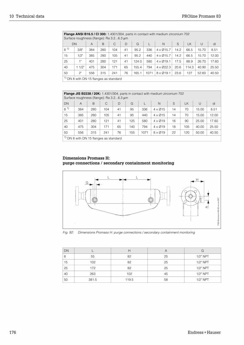
10 Technical data PROline Promass 83
176 Endress+Hauser
Dimensions Promass H:purge connections / secondary containment monitoring
Fig. 92: Dimensions Promass H: purge connections / secondary containment monitoring
Flange ANSI B16.5 / Cl 300: 1.4301/304, parts in contact with medium zirconium 702Surface roughness (flange): Ra 3.2...6.3 µm
DN A B C D G L N S LK U di
8 1) 3/8" 384 280 104 41 95.2 336 4 x Ø15.7 14.2 66.5 15.70 8.51
15 1/2" 385 280 105 41 95.2 440 4 x Ø15.7 14.2 66.5 15.70 12.00
25 1" 401 280 121 41 124.0 580 4 x Ø19.1 17.5 88.9 26.70 17.60
40 1 1/2" 475 304 171 65 155.4 794 4 x Ø22.3 20.6 114.3 40.90 25.50
50 2" 556 315 241 76 165.1 1071 8 x Ø19.1 23.6 127 52.60 40.501) DN 8 with DN 15 flanges as standard
Flange JIS B2238 / 20K: 1.4301/304, parts in contact with medium zirconium 702Surface roughness (flange): Ra 3.2...6.3 µm
DN A B C D G L N S LK U di
8 1) 384 280 104 41 95 336 4 x Ø15 14 70 15.00 8.51
15 385 280 105 41 95 440 4 x Ø15 14 70 15.00 12.00
25 401 280 121 41 125 580 4 x Ø19 16 90 25.00 17.60
40 475 304 171 65 140 794 4 x Ø19 18 105 40.00 25.50
50 556 315 241 76 155 1071 8 x Ø19 22 120 50.00 40.501) DN 8 with DN 15 flanges as standard
DN L H A G
8 55 82 25 1/2" NPT
15 102 82 25 1/2" NPT
25 172 82 25 1/2" NPT
40 263 102 45 1/2" NPT
50 381.5 119.5 58 1/2" NPT
F06-
8xxx
xxxx
-06-
05-x
x-xx
-007

PROline Promass 83 10 Technical data
Endress+Hauser 177
10.14 Dimensions: Promass I
Dimensions Promass I: flange connections EN (DIN), ANSI, JIS
Fig. 93: Dimensions Promass I: flange connections EN (DIN), ANSI, JIS
Flange EN 1092-1 (DIN 2501) / PN 40: 1.4301/304, parts in contact with medium titanium grade 9Surface roughness (flange): EN 1092-1 Form B1 (DIN 2526 Form C), Ra 6.3...12.5 µm
DN A B C G L N S LK U di
8 1) 350 291 59 95 402 4 x Ø14 20 65 17.30 8.55
15 350 291 59 95 438 4 x Ø14 20 65 17.30 11.38
15 2) 350 291 59 95 572 4 x Ø14 19 65 17.07 17.07
25 350 291 59 115 578 4 x Ø14 23 85 28.50 17.07
25 2) 377 305 72 115 700 4 x Ø14 22 85 25.60 25.60
40 377 305 72 150 708 4 x Ø18 26 110 43.10 25.60
40 2) 406 320 86 150 819 4 x Ø18 24 110 35.62 35.62
50 406 320 86 165 827 4 x Ø18 28 125 54.50 35.621) DN 8 with DN 15 flanges as standard2) DN 15, 25, 40 “FB” = Full bore versions of Promass I
Flange EN 1092-1 (DIN 2501) / PN 63: 1.4301/304, parts in contact with medium titanium grade 9Surface roughness (flange): EN 1092-1 Form B2 (DIN 2526 Form E), Ra 1.6...3.2 µm
DN A B C G L N S LK U di
50 406 320 86 180 832 4 x Ø22 34 135 54.5 35.62
Flange EN 1092-1(DIN 2501) / PN 100: 1.4301/304, parts in contact with medium titanium grade 9Surface roughness (flange): EN 1092-1 Form B2 (DIN 2526 Form E), Ra 1.6...3.2 µm
DN A B C G L N S LK U di
8 1) 350 291 59 105 402 4 x Ø14 25 75 17.30 8.55
15 350 291 59 105 438 4 x Ø14 25 75 17.30 11.38
15 2) 350 291 59 105 578 4 x Ø14 26 75 17.07 17.07
25 350 291 59 140 578 4 x Ø18 29 100 28.50 17.07
25 2) 377 305 72 140 706 4 x Ø18 31 100 25.60 25.60
40 377 305 72 170 708 4 x Ø22 32 125 42.50 25.60
40 2) 406 320 86 170 825 4 x Ø22 33 125 35.62 35.62
50 406 320 86 195 832 4 x Ø26 36 145 53.90 35.621) DN 8 with DN 15 flanges as standard2) DN 15, 25, 40 “FB” = Full bore versions of Promass I
F06-
83Ix
xxxx
-06-
00-x
x-xx
-000
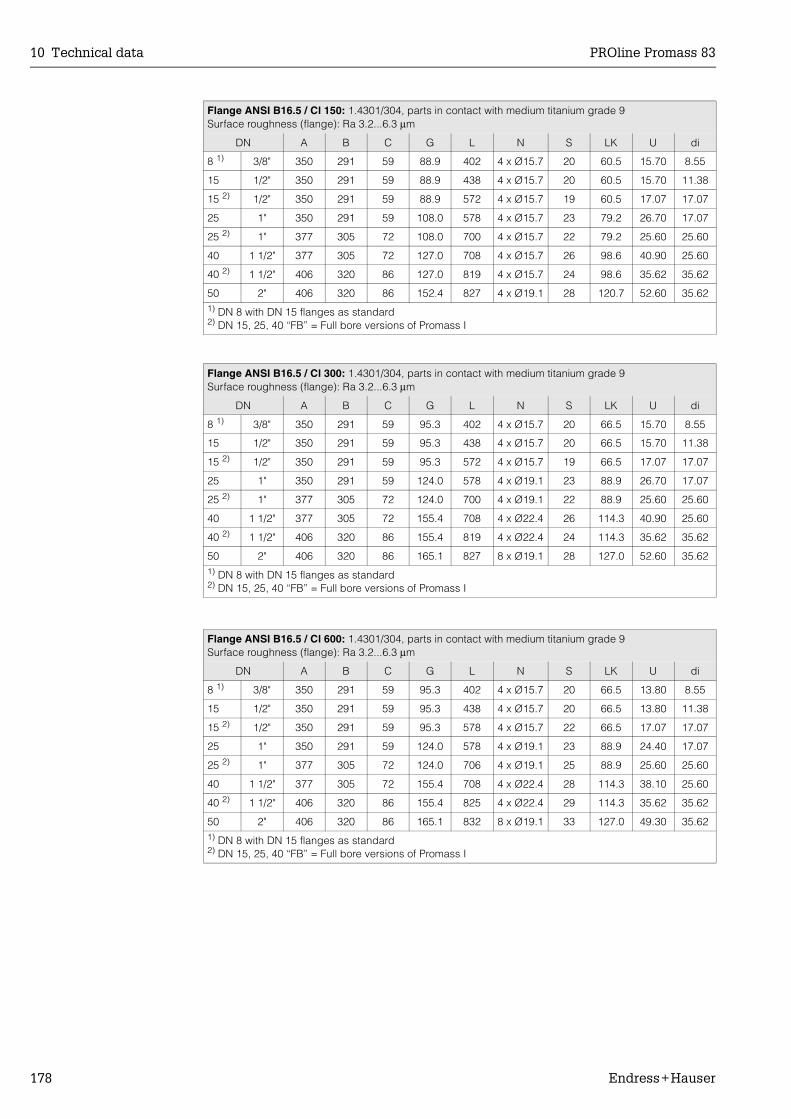
10 Technical data PROline Promass 83
178 Endress+Hauser
Flange ANSI B16.5 / Cl 150: 1.4301/304, parts in contact with medium titanium grade 9Surface roughness (flange): Ra 3.2...6.3 µm
DN A B C G L N S LK U di
8 1) 3/8" 350 291 59 88.9 402 4 x Ø15.7 20 60.5 15.70 8.55
15 1/2" 350 291 59 88.9 438 4 x Ø15.7 20 60.5 15.70 11.38
15 2) 1/2" 350 291 59 88.9 572 4 x Ø15.7 19 60.5 17.07 17.07
25 1" 350 291 59 108.0 578 4 x Ø15.7 23 79.2 26.70 17.07
25 2) 1" 377 305 72 108.0 700 4 x Ø15.7 22 79.2 25.60 25.60
40 1 1/2" 377 305 72 127.0 708 4 x Ø15.7 26 98.6 40.90 25.60
40 2) 1 1/2" 406 320 86 127.0 819 4 x Ø15.7 24 98.6 35.62 35.62
50 2" 406 320 86 152.4 827 4 x Ø19.1 28 120.7 52.60 35.621) DN 8 with DN 15 flanges as standard2) DN 15, 25, 40 “FB” = Full bore versions of Promass I
Flange ANSI B16.5 / Cl 300: 1.4301/304, parts in contact with medium titanium grade 9Surface roughness (flange): Ra 3.2...6.3 µm
DN A B C G L N S LK U di
8 1) 3/8" 350 291 59 95.3 402 4 x Ø15.7 20 66.5 15.70 8.55
15 1/2" 350 291 59 95.3 438 4 x Ø15.7 20 66.5 15.70 11.38
15 2) 1/2" 350 291 59 95.3 572 4 x Ø15.7 19 66.5 17.07 17.07
25 1" 350 291 59 124.0 578 4 x Ø19.1 23 88.9 26.70 17.07
25 2) 1" 377 305 72 124.0 700 4 x Ø19.1 22 88.9 25.60 25.60
40 1 1/2" 377 305 72 155.4 708 4 x Ø22.4 26 114.3 40.90 25.60
40 2) 1 1/2" 406 320 86 155.4 819 4 x Ø22.4 24 114.3 35.62 35.62
50 2" 406 320 86 165.1 827 8 x Ø19.1 28 127.0 52.60 35.621) DN 8 with DN 15 flanges as standard2) DN 15, 25, 40 “FB” = Full bore versions of Promass I
Flange ANSI B16.5 / Cl 600: 1.4301/304, parts in contact with medium titanium grade 9Surface roughness (flange): Ra 3.2...6.3 µm
DN A B C G L N S LK U di
8 1) 3/8" 350 291 59 95.3 402 4 x Ø15.7 20 66.5 13.80 8.55
15 1/2" 350 291 59 95.3 438 4 x Ø15.7 20 66.5 13.80 11.38
15 2) 1/2" 350 291 59 95.3 578 4 x Ø15.7 22 66.5 17.07 17.07
25 1" 350 291 59 124.0 578 4 x Ø19.1 23 88.9 24.40 17.07
25 2) 1" 377 305 72 124.0 706 4 x Ø19.1 25 88.9 25.60 25.60
40 1 1/2" 377 305 72 155.4 708 4 x Ø22.4 28 114.3 38.10 25.60
40 2) 1 1/2" 406 320 86 155.4 825 4 x Ø22.4 29 114.3 35.62 35.62
50 2" 406 320 86 165.1 832 8 x Ø19.1 33 127.0 49.30 35.621) DN 8 with DN 15 flanges as standard2) DN 15, 25, 40 “FB” = Full bore versions of Promass I

PROline Promass 83 10 Technical data
Endress+Hauser 179
Flange JIS B2238 / 10K: 1.4301/304, parts in contact with medium titanium grade 9Surface roughness (flange): Ra 3.2...6.3 µm
DN A B C G L N S LK U di
50 406 320 86 155 827 4 x Ø19 28 120 50 35.62
Flange JIS B2238 / 20K: 1.4301/304, parts in contact with medium titanium grade 9Surface roughness (flange): Ra 3.2...6.3 µm
DN A B C G L N S LK U di
8 1) 350 291 59 95 402 4 x Ø15 20 70 15.00 8.55
15 350 291 59 95 438 4 x Ø15 20 70 15.00 11.38
15 2) 350 291 59 95 572 4 x Ø15 19 70 17.07 17.07
25 350 291 59 125 578 4 x Ø19 23 90 25.00 17.07
25 2) 377 305 72 125 700 4 x Ø19 22 90 25.60 25.60
40 377 305 72 140 708 4 x Ø19 26 105 40.00 25.60
40 2) 406 320 86 140 819 4 x Ø19 24 105 35.62 35.62
50 406 320 86 155 827 8 x Ø19 28 120 50.00 35.621) DN 8 with DN 15 flanges as standard2) DN 15, 25, 40 “FB” = Full bore versions of Promass I
Flange JIS B2238 / 40K: 1.4301/304, parts in contact with medium titanium grade 9Surface roughness (flange): Ra 3.2...6.3 µm
DN A B C G L N S LK U di
8 1) 350 291 59 115 402 4 x Ø19 25 80 15.00 8.55
15 350 291 59 115 438 4 x Ø19 25 80 15.00 11.38
15 2) 350 291 59 115 578 4 x Ø19 26 80 17.07 17.07
25 350 291 59 130 578 4 x Ø19 27 95 25.00 17.07
25 2) 377 305 72 130 706 4 x Ø19 29 95 25.60 25.60
40 377 305 72 160 708 4 x Ø23 30 120 38.00 25.60
40 2) 406 320 86 160 825 4 x Ø23 31 120 35.62 35.62
50 406 320 86 165 827 8 x Ø19 32 130 50.00 35.621) DN 8 with DN 15 flanges as standard2) DN 15, 25, 40 “FB” = Full bore versions of Promass I
Flange JIS B2238 / 63K: 1.4301/304, parts in contact with medium titanium grade 9Surface roughness (flange): Ra 3.2...6.3 µm
DN A B C G L N S LK U di
8 1) 350 291 59 120 402 4 x Ø19 28 85 12.00 8.55
15 350 291 59 120 438 4 x Ø19 28 85 12.80 11.38
15 2) 350 291 59 120 578 4 x Ø19 29 85 17.07 17.07
25 350 291 59 140 578 4 x Ø23 30 100 22.00 17.07
25 2) 377 305 72 140 706 4 x Ø23 32 100 25.60 25.60
40 377 305 72 175 708 4 x Ø25 36 130 35.00 25.60
40 2) 406 320 86 175 825 4 x Ø25 37 130 35.62 35.62
50 406 320 86 185 832 8 x Ø23 40 145 48.00 35.621) DN 8 with DN 15 flanges as standard2) DN 15, 25, 40 “FB” = Full bore versions of Promass I
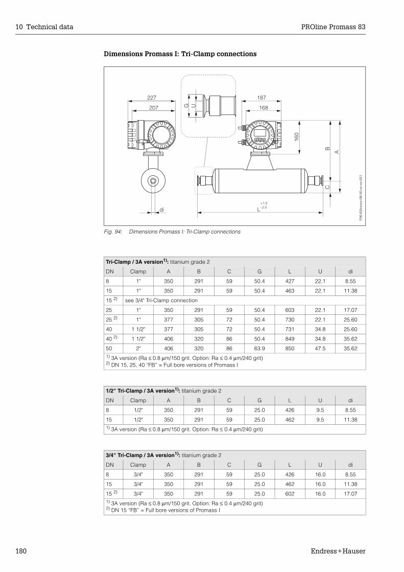
10 Technical data PROline Promass 83
180 Endress+Hauser
Dimensions Promass I: Tri-Clamp connections
Fig. 94: Dimensions Promass I: Tri-Clamp connections
Tri-Clamp / 3A version1): titanium grade 2
DN Clamp A B C G L U di
8 1" 350 291 59 50.4 427 22.1 8.55
15 1" 350 291 59 50.4 463 22.1 11.38
15 2) see 3/4" Tri-Clamp connection
25 1" 350 291 59 50.4 603 22.1 17.07
25 2) 1" 377 305 72 50.4 730 22.1 25.60
40 1 1/2" 377 305 72 50.4 731 34.8 25.60
40 2) 1 1/2" 406 320 86 50.4 849 34.8 35.62
50 2" 406 320 86 63.9 850 47.5 35.621) 3A version (Ra ≤ 0.8 µm/150 grit. Option: Ra ≤ 0.4 µm/240 grit)2) DN 15, 25, 40 “FB” = Full bore versions of Promass I
1/2" Tri-Clamp / 3A version1): titanium grade 2
DN Clamp A B C G L U di
8 1/2" 350 291 59 25.0 426 9.5 8.55
15 1/2" 350 291 59 25.0 462 9.5 11.381) 3A version (Ra ≤ 0.8 µm/150 grit. Option: Ra ≤ 0.4 µm/240 grit)
3/4" Tri-Clamp / 3A version1): titanium grade 2
DN Clamp A B C G L U di
8 3/4" 350 291 59 25.0 426 16.0 8.55
15 3/4" 350 291 59 25.0 462 16.0 11.38
15 2) 3/4" 350 291 59 25.0 602 16.0 17.071) 3A version (Ra ≤ 0.8 µm/150 grit. Option: Ra ≤ 0.4 µm/240 grit)2) DN 15 “FB” = Full bore versions of Promass I
F06-
83Ix
xxxx
-06-
00-x
x-xx
-001

PROline Promass 83 10 Technical data
Endress+Hauser 181
Dimensions Promass I: DIN 11851 connections (hygienic coupling)
Fig. 95: Dimensions Promass I: DIN 11851 connections (hygienic coupling)
Hygienic coupling DIN 11851 / 3A version 1): titanium grade 2
DN A B C G L U di
8 350 291 59 Rd 34 x 1/8" 427 16 8.55
15 350 291 59 Rd 34 x 1/8" 463 16 11.38
15 2) 350 291 59 Rd 34 x 1/8" 602 16 17.07
25 350 291 59 Rd 52 x 1/6" 603 26 17.07
25 2) 377 305 72 Rd 52 x 1/6" 736 26 25.60
40 377 305 72 Rd 65 x 1/6" 731 38 25.60
40 2) 406 320 86 Rd 65 x 1/6" 855 38 35.62
50 406 320 86 Rd 78 x 1/6" 856 50 35.621) 3A version (Ra ≤ 0.8 µm/150 grit)2) DN 15, 25, 40 “FB” = Full bore versions of Promass I
Hygienic coupling DIN 11851 Rd 28 x 1/8" / 3A version 1): titanium grade 2
DN A B C G L U di
8 350 291 59 Rd 28 x 1/8" 426 10 8.55
15 350 291 59 Rd 28 x 1/8" 462 10 11.381) 3A version (Ra ≤ 0.8 µm/150 grit)
F06-
83Ix
xxxx
-06-
00-x
x-xx
-003

10 Technical data PROline Promass 83
182 Endress+Hauser
Dimensions Promass I: DIN 11864-1 Form A connections (couplings)
Fig. 96: Dimensions Promass I: DIN 11864-1 Form A connections (couplings)
Coupling DIN 11864-1 Form A / 3A version 1): titanium grade 2
DN A B C G L U di
8 2) 350 291 59 Rd 28 x 1/8" 428 10 8.55
15 350 291 59 Rd 34 x 1/8" 463 16 11.38
15 3) 350 291 59 Rd 34 x 1/8" 602 16 17.07
25 350 291 59 Rd 52 x 1/6" 603 26 17.07
25 3) 377 305 72 Rd 52 x 1/6" 734 26 25.60
40 377 305 72 Rd 65 x 1/6" 731 38 25.60
40 3) 406 320 86 Rd 65 x 1/6" 855 38 35.62
50 406 320 86 Rd 78 x 1/6" 856 50 35.621) 3A version (Ra ≤ 0.8 µm/150 grit. Option: Ra ≤ 0.4 µm/240 grit)2) DN 8 with DN 10 threaded adapters3) DN 15, 25, 40 “FB” = Full bore versions of Promass I
F06-
83Ix
xxxx
-06-
00-x
x-xx
-004
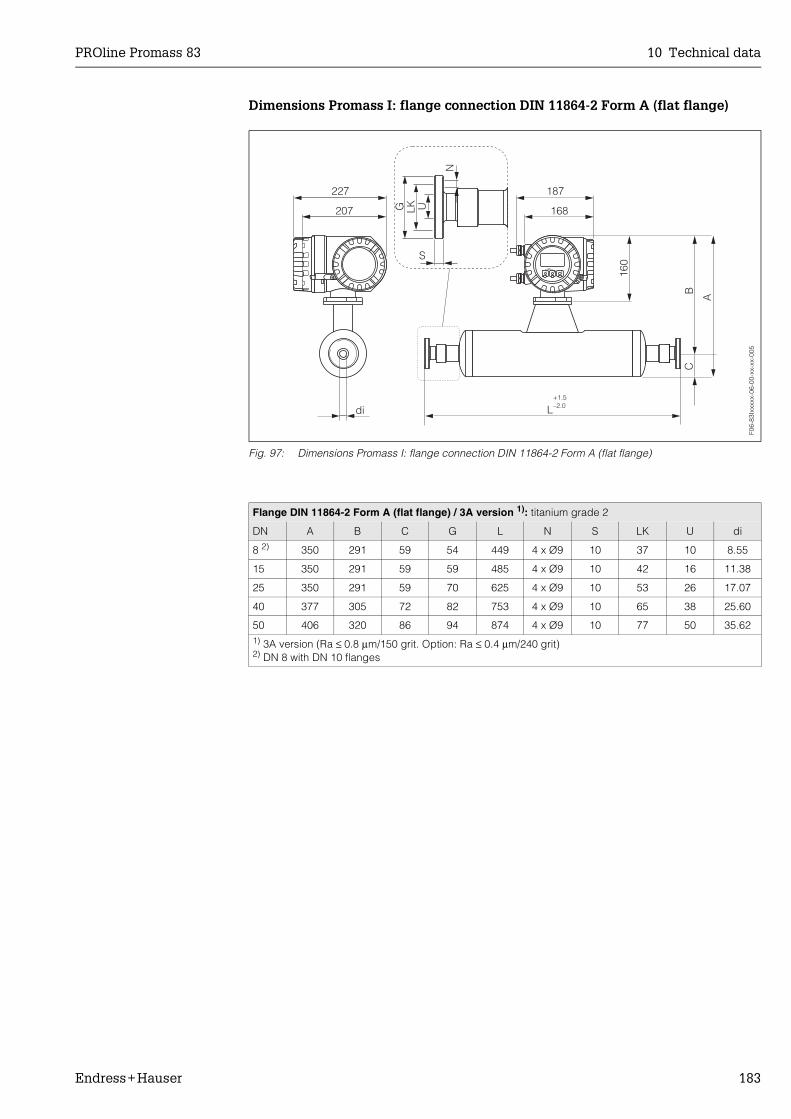
PROline Promass 83 10 Technical data
Endress+Hauser 183
Dimensions Promass I: flange connection DIN 11864-2 Form A (flat flange)
Fig. 97: Dimensions Promass I: flange connection DIN 11864-2 Form A (flat flange)
Flange DIN 11864-2 Form A (flat flange) / 3A version 1): titanium grade 2
DN A B C G L N S LK U di
8 2) 350 291 59 54 449 4 x Ø9 10 37 10 8.55
15 350 291 59 59 485 4 x Ø9 10 42 16 11.38
25 350 291 59 70 625 4 x Ø9 10 53 26 17.07
40 377 305 72 82 753 4 x Ø9 10 65 38 25.60
50 406 320 86 94 874 4 x Ø9 10 77 50 35.621) 3A version (Ra ≤ 0.8 µm/150 grit. Option: Ra ≤ 0.4 µm/240 grit)2) DN 8 with DN 10 flanges
F06-
83Ix
xxxx
-06-
00-x
x-xx
-005

10 Technical data PROline Promass 83
184 Endress+Hauser
Dimensions Promass I: ISO 2853 connections (couplings)
Fig. 98: Dimensions Promass I: ISO 2853 connections (couplings)
Coupling ISO 2853 / 3A version 1): titanium grade 2
DN A B C G L U di
8 2) 350 291 59 37.13 435 22.6 8.55
15 350 291 59 37.13 471 22.6 11.38
15 3) 350 291 59 37.13 610 22.6 17.07
25 3) 377 305 72 37.13 744 22.6 25.60
40 377 305 72 50.65 737 35.6 25.60
40 3) 406 320 86 50.65 859 35.6 35.62
50 406 320 86 64.16 856 48.6 35.621) 3A version (Ra ≤ 0.8 µm/150 grit. Option: Ra ≤ 0.4 µm/240 grit)2) DN 8 with DN 15 threaded adapters as standard3) DN 15, 25, 40 “FB” = Full bore versions of Promass I
F06-
83Ix
xxxx
-06-
00-x
x-xx
-006
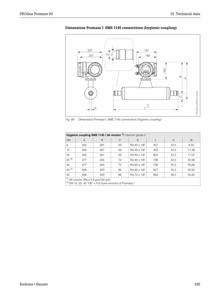
PROline Promass 83 10 Technical data
Endress+Hauser 185
Dimensions Promass I: SMS 1145 connections (hygienic coupling)
Fig. 99: Dimensions Promass I: SMS 1145 connections (hygienic coupling)
Hygienic coupling SMS 1145 / 3A version 1): titanium grade 2
DN A B C G L U di
8 350 291 59 Rd 40 x 1/6" 427 22.5 8.55
15 350 291 59 Rd 40 x 1/6" 463 22.5 11.38
25 350 291 59 Rd 40 x 1/6" 603 22.5 17.07
25 2) 377 305 72 Rd 40 x 1/6" 736 22.5 25.60
40 377 305 72 Rd 60 x 1/6" 738 35.5 25.60
40 2) 406 320 86 Rd 60 x 1/6" 857 35.5 35.62
50 406 320 86 Rd 70 x 1/6" 858 48.5 35.621) 3A version (Ra ≤ 0.8 µm/150 grit)2) DN 15, 25, 40 “FB” = Full bore versions of Promass I
F06-
83Ix
xxxx
-06-
00-x
x-xx
-002
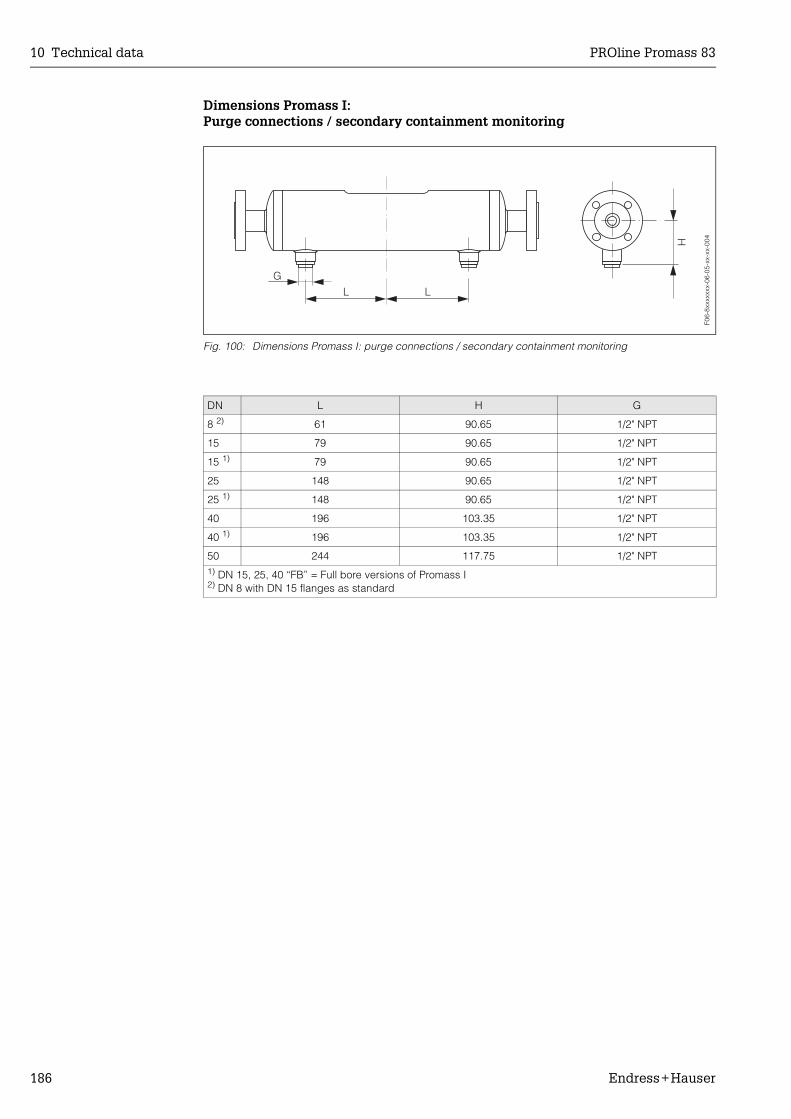
10 Technical data PROline Promass 83
186 Endress+Hauser
Dimensions Promass I: Purge connections / secondary containment monitoring
Fig. 100: Dimensions Promass I: purge connections / secondary containment monitoring
DN L H G
8 2) 61 90.65 1/2" NPT
15 79 90.65 1/2" NPT
15 1) 79 90.65 1/2" NPT
25 148 90.65 1/2" NPT
25 1) 148 90.65 1/2" NPT
40 196 103.35 1/2" NPT
40 1) 196 103.35 1/2" NPT
50 244 117.75 1/2" NPT1) DN 15, 25, 40 “FB” = Full bore versions of Promass I2) DN 8 with DN 15 flanges as standard
F06-
8xxx
xxxx
-06-
05-x
x-xx
-004

PROline Promass 83 Index
Endress+Hauser 187
Index
AAccessories . . . . . . . . . . . . . . . . . . . . . . . . . . . . . . . 87Accuracy
see Performance characteristicsAdvanced Diagnostics (optional software) . . . . . . . 80Ambient temperature . . . . . . . . . . . . . . . . . . . . . . . 119Applications . . . . . . . . . . . . . . . . . . . . . . . . . . . . . . 111Applicator (selection and configuration software) . . 87Auxiliary input
see Status input
BBatching
Quick Setup menu . . . . . . . . . . . . . . . . . . . . . . . 65Using the display as a batch controller . . . . . . . 39
Boardssee Spare parts
CCable entries
Degree of protection . . . . . . . . . . . . . . . . . . . . . . 32Technical data . . . . . . . . . . . . . . . . . . . . . . . . . 114
Cable specifications (remote version) . . . . . . . . . . . 26Calibration factor (default) . . . . . . . . . . . . . . . . . . . . 10CE mark (declaration of conformity) . . . . . . . . . . . . 10CIP cleaning . . . . . . . . . . . . . . . . . . . . . . . . . . . 86, 119Cleaning
CIP cleaning . . . . . . . . . . . . . . . . . . . . . . . . . . . . 86Exterior cleaning . . . . . . . . . . . . . . . . . . . . . . . . . 86SIP cleaning . . . . . . . . . . . . . . . . . . . . . . . . . . . . 86
Code entry (function matrix) . . . . . . . . . . . . . . . . . . 41Commissioning
“Batching” Quick Setup . . . . . . . . . . . . . . . . . . . 65“Commissioning” Quick Setup . . . . . . . . . . . . . . 60“Gas Measurement” Quick Setup . . . . . . . . . . . . 69“Pulsating Flow” Quick Setup . . . . . . . . . . . . . . . 62Advanced diagnostic functions . . . . . . . . . . . . . 80Concentration measurement functions . . . . . . . . 75Configuring relay contact (NC/NO) . . . . . . . . . . 84Configuring the current output (active/passive) . 82Density adjustment . . . . . . . . . . . . . . . . . . . . . . . 72Zero point adjustment . . . . . . . . . . . . . . . . . . . . . 71
Commubox FXA 191 . . . . . . . . . . . . . . . . . . . . . . . . 31Communication . . . . . . . . . . . . . . . . . . . . . . . . . . . . 43Concentration measurement . . . . . . . . . . . . . . . . . . 75Configuring current input/output (active/passive) . . 82Connection
see Electrical connectionCurrent output
Configuration active/passive . . . . . . . . . . . . . . . 82Electrical connection . . . . . . . . . . . . . . . . . . . . . 30Technical data . . . . . . . . . . . . . . . . . . . . . . . . . 113
DData storage (S-DAT, T-DAT, F-CHIP) . . . . . . . . . . . 85Declaration of conformity (CE mark) . . . . . . . . . . . . 10
Declaration of contamination (form for repairs) . . . . . 8Degree of protection . . . . . . . . . . . . . . . . . . . . 32, 119Density adjustment . . . . . . . . . . . . . . . . . . . . . . . . . . 72Density functions
see Concentration measurementDesign
see DimensionsDesignated use . . . . . . . . . . . . . . . . . . . . . . . . . . . . . . 7Device designation . . . . . . . . . . . . . . . . . . . . . . . . . . . 9Device functions
see “Description of Device Functions” ManualDiagnosis functions, advanced (optional software) . 80Dimensions
High-temperature (compact) . . . . . . . . . . . . . . . 135High-temperature (remote) . . . . . . . . . . . . . . . . 135Promass A / process connections . . . . . . . . . . . 169Promass E / process connections . . . . . . . . . . . 160Promass F / process connections . . . . . . . . . . . 136Promass H / process connections . . . . . . . . . . . 175Promass I / process connections . . . . . . . . . . . 177Promass M / process connections . . . . . . . . . . 146Remote version (Promass E) . . . . . . . . . . . . . . . 134Remote version (Promass F, M, A, H, I) . . . . . . . 134Remote version for heating . . . . . . . . . . . . . . . . 134Stainless steel field housing . . . . . . . . . . . . . . . 133Wall-mount housing . . . . . . . . . . . . . . . . . . . . . . 133
DisplayDisplay and operating elements . . . . . . . . . . . . . 35Readings displayed . . . . . . . . . . . . . . . . . . . . . . . 36Turning the display . . . . . . . . . . . . . . . . . . . . . . . 23Using the display as a batch controller . . . . . . . . 39
Documentation, additional . . . . . . . . . . . . . . . . . . . 132
EElectrical connection
Cable specifications (remote version) . . . . . . . . . 26Commubox FXA 191 . . . . . . . . . . . . . . . . . . . . . . 31Degree of protection . . . . . . . . . . . . . . . . . . . . . . 32HART handheld communicator . . . . . . . . . . . . . . 31Post connection check (checklist) . . . . . . . . . . . . 33Remote version . . . . . . . . . . . . . . . . . . . . . . . . . . 25Transmitter, terminal assignment . . . . . . . . . . . . . 29
Electronics boards (replacing, installing)Field housing . . . . . . . . . . . . . . . . . . . . . . . . . . . 104Wall-mount housing . . . . . . . . . . . . . . . . . . . . . . 106
Environment conditions . . . . . . . . . . . . . . . . . . . . . . 119Error limits
see Performance characteristicsError messages
Display mode . . . . . . . . . . . . . . . . . . . . . . . . . . . . 42Process errors (application errors) . . . . . . . . . . . 98System errors (device errors) . . . . . . . . . . . . . . . 90
Error response (inputs/outputs) . . . . . . . . . . . . . . . 101Error types (system and process errors) . . . . . . . . . 42European Pressure Equipment Directive . . . . . . . . 131Ex certification . . . . . . . . . . . . . . . . . . . . . . . . . . . . . 131

Index PROline Promass 83
188 Endress+Hauser
ExchangeDevice fuse . . . . . . . . . . . . . . . . . . . . . . . . . . . . 108Printed circuit boards . . . . . . . . . . . . . . . . . . . . 104Seals (for Promass A and M) . . . . . . . . . . . . . . . 86
Exterior cleaning . . . . . . . . . . . . . . . . . . . . . . . . . . . 86
FF-CHIP (Function-Chip) . . . . . . . . . . . . . . . . . . . . . . 85FieldCheck (tester and simulator) . . . . . . . . . . . . . . 88FieldTool (configuration and service software) . . . . 88Fitting length
see DimensionsFlow direction . . . . . . . . . . . . . . . . . . . . . . . . . . 16, 17Fluid pressure range . . . . . . . . . . . . . . . . . . . . . . . 120Fluid temperature ranges . . . . . . . . . . . . . . . . . . . . 119Frequency output
Electrical connection . . . . . . . . . . . . . . . . . . . . . . 30Technical data . . . . . . . . . . . . . . . . . . . . . . . . . 113
Function check . . . . . . . . . . . . . . . . . . . . . . . . . . . . . 59Function descriptions
see “Description of Device Functions” manualFunction matrix . . . . . . . . . . . . . . . . . . . . . . . . . . . . . 40Functions, function blocks, function groups . . . . . . 40Fuse, replacing . . . . . . . . . . . . . . . . . . . . . . . . . . . 108
GGalvanic isolation . . . . . . . . . . . . . . . . . . . . . . . . . . 113Gas measurement . . . . . . . . . . . . . . . . . . . . . . . . . . 69
HHART
Command groups . . . . . . . . . . . . . . . . . . . . . . . . 43Command numbers . . . . . . . . . . . . . . . . . . . . . . 46Device status, error messages . . . . . . . . . . . . . . 52Electrical connection . . . . . . . . . . . . . . . . . . . . . . 31Handheld communicator . . . . . . . . . . . . . . . . . . 44Operating possibilities . . . . . . . . . . . . . . . . . . . . 44Switching write protection on and off . . . . . . . . . 57
Hazardous substances . . . . . . . . . . . . . . . . . . . . . . . 8Heating (general notes, insulation, etc.) . . . . . . . . . 18HOME position (operating mode) . . . . . . . . . . . . . . 35
IIncoming acceptance . . . . . . . . . . . . . . . . . . . . . . . 13Inlet runs . . . . . . . . . . . . . . . . . . . . . . . . . . . . . . . . . . 19Input signal . . . . . . . . . . . . . . . . . . . . . . . . . . . . . . . 113Input variables . . . . . . . . . . . . . . . . . . . . . . . . . . . . 111Inputs/outputs (electrical values) . . . . . . . . . . . . . . . 30Inputs/outputs, response to errors . . . . . . . . . . . . . 101Installation conditions
Dimensions, fitting lengths . . . . . . . . . . . . . . . . . 14Inlet and outlet runs . . . . . . . . . . . . . . . . . . . . . . 19Location . . . . . . . . . . . . . . . . . . . . . . . . . . . . . . . 14Orientation (vertical, horizontal) . . . . . . . . . . . . . 16System pressure . . . . . . . . . . . . . . . . . . . . . . . . . 15Vertical pipelines . . . . . . . . . . . . . . . . . . . . . . . . . 15Vibrations . . . . . . . . . . . . . . . . . . . . . . . . . . . . . . 19
Insulation of sensors . . . . . . . . . . . . . . . . . . . . . . . . 19
LLimiting flow
see Measuring rangeLimiting medium pressure range . . . . . . . . . . . . . 120Load . . . . . . . . . . . . . . . . . . . . . . . . . . . . . . . . . . . 113Local display
see DisplayLow flow cutoff . . . . . . . . . . . . . . . . . . . . . . . . . . . 113
MMaintenance . . . . . . . . . . . . . . . . . . . . . . . . . . . . . . 86Material load curves . . . . . . . . . . . . . . . . . . . . . . . 130Materials . . . . . . . . . . . . . . . . . . . . . . . . . . . . . . . . 128Measured variables . . . . . . . . . . . . . . . . . . . . . . . . 111Measuring accuracy
see Performance characteristicsMeasuring principle . . . . . . . . . . . . . . . . . . . . . . . 111Measuring range . . . . . . . . . . . . . . . . . . . . . . . . . . 111Measuring system . . . . . . . . . . . . . . . . . . . . . . . . . 111Mounting the sensor
see Installation conditionsMounting the wall-mount housing (remote version) 21
NNameplate
Sensor . . . . . . . . . . . . . . . . . . . . . . . . . . . . . . . . 10Transmitter . . . . . . . . . . . . . . . . . . . . . . . . . . . . . . 9
NC (relay contact) . . . . . . . . . . . . . . . . . . . . . . . . . . 84NO (relay contact) . . . . . . . . . . . . . . . . . . . . . . . . . . 84Nominal pressure
see Limiting medium pressure range
OOperable flow range . . . . . . . . . . . . . . . . . . . . . . . 112Operating conditions . . . . . . . . . . . . . . . . . . . . . . . 119Operation
Display and operating elements . . . . . . . . . . . . 35FieldtooI (configuration and service software) . . 44Function matrix . . . . . . . . . . . . . . . . . . . . . . . . . . 40HART handheld communicator . . . . . . . . . . . . . 44
Operational safety . . . . . . . . . . . . . . . . . . . . . . . . . . . 7Ordering code
Accessories . . . . . . . . . . . . . . . . . . . . . . . . . . . . 87Sensor . . . . . . . . . . . . . . . . . . . . . . . . . . . . . . . . 10Transmitter . . . . . . . . . . . . . . . . . . . . . . . . . . . . . . 9
Ordering information . . . . . . . . . . . . . . . . . . . . . . . 132Outlet runs . . . . . . . . . . . . . . . . . . . . . . . . . . . . . . . . 19Output signal . . . . . . . . . . . . . . . . . . . . . . . . . . . . . 113Output variables . . . . . . . . . . . . . . . . . . . . . . . . . . 113
PPerformance characteristics
Influence of fluid pressure . . . . . . . . . . . . . . . . 118Influence of fluid temperature . . . . . . . . . . . . . 117Maximum measured error . . . . . . . . . . . . . . . . 115Reference operating conditions . . . . . . . . . . . . 115Repeatability . . . . . . . . . . . . . . . . . . . . . . . . . . 117
Post-installation check (checklist) . . . . . . . . . . . . . . 23Power consumption . . . . . . . . . . . . . . . . . . . . . . . . 114Power supply (voltage supply) . . . . . . . . . . . . . . . 114
PROline Promass 83 Index
Endress+Hauser 189
Power supply failure . . . . . . . . . . . . . . . . . . . . . . . . 114Pressure device approval . . . . . . . . . . . . . . . . . . . 131Pressure loss (formulas, pressure loss diagrams) . 121Pressure monitoring connections . . . . . . . . . . . . . . 85Pressure range
see Limiting medium pressure rangePrinted circuit boards (removing/installing)
Field housing . . . . . . . . . . . . . . . . . . . . . . . . . . 104Wall-mount housing . . . . . . . . . . . . . . . . . . . . . 106
Process connections . . . . . . . . . . . . . . . . . . . . . . . 130Process errors
Definition . . . . . . . . . . . . . . . . . . . . . . . . . . . . . . . 42Process error messages (display) . . . . . . . . . . . 98Process errors without messages . . . . . . . . . . . 100
Programming modeDisable . . . . . . . . . . . . . . . . . . . . . . . . . . . . . . . . 42Enable . . . . . . . . . . . . . . . . . . . . . . . . . . . . . . . . . 41
Pulsating flow . . . . . . . . . . . . . . . . . . . . . . . . . . . . . . 62Pulse output
see Frequency outputPumps
Mounting location, system pressure . . . . . . . . . . 15Pump types, pulsating flow . . . . . . . . . . . . . . . . . 62
Purge connections . . . . . . . . . . . . . . . . . . . . . . . . . . 85
QQuick Setup
Batching . . . . . . . . . . . . . . . . . . . . . . . . . . . . . . . 65Commissioning . . . . . . . . . . . . . . . . . . . . . . . . . . 60Gas Measurement . . . . . . . . . . . . . . . . . . . . . . . 69Pulsating flows . . . . . . . . . . . . . . . . . . . . . . . . . . 63
RRegistered trademarks . . . . . . . . . . . . . . . . . . . . . . 11Relay output
Configuring relay contact (NC, NO) . . . . . . . . . . 84Electrical connection . . . . . . . . . . . . . . . . . . . . . 30Technical data . . . . . . . . . . . . . . . . . . . . . . . . . 113
Repair . . . . . . . . . . . . . . . . . . . . . . . . . . . . . . . . . . . . . 8Repeatability (measuring accuracy) . . . . . . . . . . . 117Returning devices . . . . . . . . . . . . . . . . . . . . . . . . . . . 8
SSafety icons . . . . . . . . . . . . . . . . . . . . . . . . . . . . . . . . 8Safety instructions . . . . . . . . . . . . . . . . . . . . . . . . . . . 7Safety of operation . . . . . . . . . . . . . . . . . . . . . . . . . . . 7Safety regulation form
see Declaration of contaminationSanitary compatibility . . . . . . . . . . . . . . . . . . . . . . . 131S-DAT . . . . . . . . . . . . . . . . . . . . . . . . . . . . . . . . . . . . 85Seals
Fluid temperature ranges . . . . . . . . . . . . . . . . . 119Materials . . . . . . . . . . . . . . . . . . . . . . . . . . . . . . 130Replacement . . . . . . . . . . . . . . . . . . . . . . . . . . . . 86
Secondary containmentGas purging, pressure monitoring connections . 85Pressure range . . . . . . . . . . . . . . . . . . . . . . . . . 120
Sensor installationsee Installation conditions
Serial number . . . . . . . . . . . . . . . . . . . . . . . . . . . . 9, 10
Shock resistance . . . . . . . . . . . . . . . . . . . . . . . . . . . 119Signal on alarm . . . . . . . . . . . . . . . . . . . . . . . . . . . . 113SIP cleaning . . . . . . . . . . . . . . . . . . . . . . . . . . 86, 119Software
Amplifier display . . . . . . . . . . . . . . . . . . . . . . . . . 59Versions (history) . . . . . . . . . . . . . . . . . . . . . . . . 109
Spare parts . . . . . . . . . . . . . . . . . . . . . . . . . . . . . . . 103Standards, guidelines . . . . . . . . . . . . . . . . . . . . . . . 131Status input
Electrical connection . . . . . . . . . . . . . . . . . . . . . . 30Technical data . . . . . . . . . . . . . . . . . . . . . . . . . . 113
Storage . . . . . . . . . . . . . . . . . . . . . . . . . . . . . . . . . . . 14Supplementary Ex documentation . . . . . . . . . . . . . . . 7Supply voltage (power supply) . . . . . . . . . . . . . . . . 114Switching output
see Relay outputSystem error
Definition . . . . . . . . . . . . . . . . . . . . . . . . . . . . . . . 42System error messages (display) . . . . . . . . . . . . 90
System pressure, requirements . . . . . . . . . . . . . . . . 15
TT-DAT (Transmitter-DAT) . . . . . . . . . . . . . . . . . . . . . 85Technical data . . . . . . . . . . . . . . . . . . . . . . . . . . . . 111Temperature ranges
Ambient temperature . . . . . . . . . . . . . . . . . . . . . 119Fluid temperature . . . . . . . . . . . . . . . . . . . . . . . . 119Storage temperature . . . . . . . . . . . . . . . . . . . . . 119
Thermal insulation, general notes . . . . . . . . . . . . . . . 19Transmitter
Electrical connection . . . . . . . . . . . . . . . . . . . . . . 27Installing the wall-mount housing . . . . . . . . . . . . 21Turning the field housing (aluminum) . . . . . . . . . 20Turning the field housing (stainless steel) . . . . . . 20
Transporting the sensor . . . . . . . . . . . . . . . . . . . . . . 13Trouble-shooting and remedy . . . . . . . . . . . . . . . . . . 89
UUser interface
see Display
VVertical pipelines . . . . . . . . . . . . . . . . . . . . . . . . . . . . 15Vibration resistance . . . . . . . . . . . . . . . . . . . . . . . . 119Vibrations . . . . . . . . . . . . . . . . . . . . . . . . . . . . . . . . . 19
WWall-mount housing, installing . . . . . . . . . . . . . . . . . 21Weight . . . . . . . . . . . . . . . . . . . . . . . . . . . . . . . . . . . 128Wiring
see Electrical connection
ZZero point adjustment . . . . . . . . . . . . . . . . . . . . . . . . 71

Index PROline Promass 83
190 Endress+Hauser

More information about services and repairs:www.services.endress.com
Dear customer,Because of legal determinations and for the safety of our employees and operating equipment we need this“Declaration of contamination” with your signature before your order can be handled. Please put the completelyfilled in declaration to the instrument and to the shipping documents in any case. Add also safety sheets and/orspecific handling instructions if necessary.
type of instrument / sensor: __________________________________ serial number: _______________________
medium / concentration: __________________________________ temperature: ______ pressure: _______
cleaned with: __________________________________ conductivity: ______ viscosity: _______
radioactive
explosive
caustic
poisonous
harmful to
health
biologicallyhazardous
inflammable
safe
Please mark the appropriate warning hints.
company: ______________________________ contact person: _________________________
______________________________ _________________________
______________________________ department: _________________________
address: ______________________________ phone number: _________________________
______________________________ fax / e-mail: _________________________
______________________________ your order no.: _________________________
I hereby certify that the returned equipment has been cleaned and decontaminated acc. to good industrial prac-tices and is in compliance with all regulations. This equipment poses no health or safety risks due to contamination.
_______________________________ ___________________________________(Date) (company stamp and legally binding signature)
SAFE

BA059D/06/en/10.0350098470FM+SGML 6.0
Members of the Endress+Hauser group
http://www.endress.com
05.03
Europe
Austria – Wien Endress+Hauser Ges.m.b.H.Tel. (01) 88 05 60, Fax (01) 88 05 63 35
Belarus – MinskBelorgsintezTel. (017) 2 50 84 73, Fax (017) 2 50 85 83
Belgium / Luxembourg – Bruxelles Endress+Hauser S.A. / N.V.Tel. (02) 2 48 06 00, Fax (02) 2 48 05 53
Bulgaria – SofiaIntertech-Automation Ltd.Tel. (02) 9 62 71 52, Fax (02) 9 62 14 71
Croatia – Zagreb Endress+Hauser GmbH+Co.Tel. (01) 6 63 77 85, Fax (01) 6 63 78 23
Cyprus – NicosiaI+G Electrical Services Co. Ltd.Tel. (02) 48 47 88, Fax (02) 48 46 90
Czech Republic – Praha Endress+Hauser Czech s.r.o.Tel. (02) 66 78 42 00, Fax (026) 66 78 41 79
Denmark – Søborg Endress+Hauser A/STel. (70) 13 11 32, Fax (70) 13 21 33
Estonia – TartuElvi-Aqua OÜTel. (7) 30 27 32, Fax (7) 30 27 31
Finland – Helsinki Metso Endress+Hauser OyTel. (204) 8 31 60, Fax (204) 8 31 61
France – Huningue Endress+Hauser S.A.Tel. (389) 69 67 68, Fax (389) 69 48 02
Germany – Weil am Rhein Endress+Hauser Messtechnik GmbH+Co. KGTel. (07621) 9 75 01, Fax (07621) 97 55 55
Great Britain – Manchester Endress+Hauser Ltd.Tel. (0161) 2 86 50 00, Fax (0161) 9 98 18 41
Greece – AthensI & G Building Services Automation S.A.Tel. (01) 9 24 15 00, Fax (01) 9 22 17 14
Hungary – Budapest Endress+Hauser MagyarországTel. (01) 4 12 04 21, Fax (01) 4 12 04 24
Iceland – ReykjavikSindra-Stál hfTel. 5 75 00 00, Fax 5 75 00 10
Ireland – Clane / County Kildare Flomeaco Endress+Hauser Ltd.Tel. (045) 86 86 15, Fax (045) 86 81 82
Italy – Cernusco s/N, Milano Endress+Hauser S.p.A.Tel. (02) 92 19 21, Fax (02) 92 19 23 62
Latvia – RigaElekoms Ltd.Tel. (07) 33 64 44, Fax (07) 33 64 48
Lithuania – KaunasUAB Agava Ltd.Tel. (03) 7 20 24 10, Fax (03) 7 20 74 14
Macedonia – BeogradMeris d.o.o.Tel. (11) 44 42 96 6, Fax (11) 30 85 77 8
Moldavia – ChisinauS.C. Techno Test SRLTel. (02) 22 61 60, Fax (02) 22 83 13
Netherlands – Naarden Endress+Hauser B.V.Tel. (035) 6 95 86 11, Fax (035) 6 95 88 25
Norway – Lierskogen Endress+Hauser A/STel. 32 85 98 50, Fax 32 85 98 51
Poland – Wroclaw Endress+Hauser Polska Sp. z o.o.Tel. (071) 7 80 37 00, Fax (071) 7 80 37 60
Portugal – Cacem Endress+Hauser Lda.Tel. (21) 4 26 72 90, Fax (21) 4 26 72 99
Romania – BucharestRomconseng S.R.L.Tel. (021) 41 12 50 1, Fax (021) 41 01 63 4
Russia – Moscow Endress+Hauser GmbH+CoTel. (095) 78 32 85 0, Fax (095) 78 32 85 5
Slovak Republic – BratislavaTranscom Technik s.r.o.Tel. (2) 44 88 86 90, Fax (2) 44 88 71 12
Slovenia – Ljubljana Endress+Hauser (Slovenija) D.O.O.Tel. (01) 5 19 22 17, Fax (01) 5 19 22 98
Spain – Sant Just Desvern Endress+Hauser S.A.Tel. (93) 4 80 33 66, Fax (93) 4 73 38 39
Sweden – Sollentuna Endress+Hauser ABTel. (08) 55 51 16 00, Fax (08) 55 51 16 55
Switzerland – Reinach/BL 1 Endress+Hauser Metso AGTel. (061) 7 15 75 75, Fax (061) 7 11 16 50
Turkey – Levent/IstanbulIntek Endüstriyel Ölcü ve Kontrol SistemleriTel. (0212) 2 75 13 55, Fax (0212) 2 66 27 75
Ukraine – KievPhotonika GmbHTel. (44) 2 68 81 02, Fax (44) 2 69 07 05
Yugoslavia Republic – BeogradMeris d.o.o.Tel. (11) 4 44 29 66, Fax (11) 3 08 57 78
Africa
Algeria – AnnabaSymes Systemes et MesuresTel. (38) 88 30 03, Fax (38) 88 30 02
Egypt – Heliopolis/CairoAnasia Egypt For Trading (S.A.E.)Tel. (02) 2 68 41 59, Fax (02) 2 68 41 69
Morocco – CasablancaOussama S.A.Tel. (02) 22 24 13 38, Fax (02) 2 40 26 57
Rep. South Africa – Sandton Endress+Hauser (Pty.) Ltd.Tel. (011) 2 62 80 00, Fax (011) 2 62 80 62
Tunisia – TunisCMR Controle, Maintenance et RegulationTel. (07) 17 93 07 7, Fax (07) 17 88 59 5
America
Argentina – Buenos Aires Endress+Hauser Argentina S.A.Tel. (11) 45 22 79 70, Fax (11) 45 22 79 09
Brazil – Sao Paulo Samson Endress+Hauser Ltda.Tel. (011) 50 33 43 33, Fax (011) 50 31 30 67
Canada – Burlington, Ontario Endress+Hauser Canada Ltd.Tel. (905) 68 19 29 2, Fax (905) 68 19 44 4
Chile – Santiago de Chile Endress+Hauser (Chile) Ltd.Tel. (02) 3 21 30 09, Fax (02) 3 21 30 25
Colombia – Bogota D.C.Colsein Ltda.Tel. (01) 2 36 76 59, Fax (01) 6 10 78 68
Costa Rica – San JoseEuro-Tec S.A.Tel. 2 20 28 08, Fax 2 96 15 42
Ecuador – QuitoInsetec Cia. Ltda.Tel. (02) 2 26 91 48, Fax (02) 2 46 18 33
El Salvador – San SalvadorAutomatizacion y Control Industrial de El Salvador, S.A. de C.V.Tel. 2 60 24 24, Fax 2 60 56 77
Guatemala – Ciudad de GuatemalaAutomatizacion y Control Industrial, S.A.Tel. (03) 34 59 85, Fax (03) 32 74 31
Honduras – San Pedro Sula, CortesAutomatizacion y Control Industrial de Honduras, S.A. de C.V.Tel. 5 57 91 36, Fax 5 57 91 39
Mexico – México, D.F Endress+Hauser (México), S.A. de C.V.Tel. (5) 5 55 68 24 07, Fax (5) 5 55 68 74 59
Nicaragua – ManaguaAutomatización y Control Industrial de Nicaragua, S.A.Tel. 2 22 61 90, Fax 2 28 70 24
Peru – MirafloresCorsusa InternationalTel. (1) 44 41 20 0, Fax (1) 44 43 66 4
USA – Greenwood, Indiana Endress+Hauser Inc.Tel. (317) 5 35 71 38, Fax (317) 5 35 84 98
USA – Norcross, Atlanta Endress+Hauser Systems & Gauging Inc.Tel. (770) 4 47 92 02, Fax (770) 4 47 57 67
Venezuela – CaracasControval C.A.Tel. (212) 9 44 09 66, Fax (212) 9 44 45 54
Asia
Azerbaijan – BakuModcon Systems - BakuTel. (12) 92 98 59, Fax (12) 99 13 72
Brunei – Negara Brunei DarussalamAmerican International Industries (B) Sdn. Bhd.Tel. (3) 22 37 37, Fax (3) 22 54 58
Cambodia – Khan Daun Penh, Phom PenhComin Khmere Co. Ltd.Tel. (23) 42 60 56, Fax (23) 42 66 22
China – Shanghai Endress+Hauser (Shanghai) Instrumentation Co. Ltd.Tel. (021) 54 90 23 00, Fax (021) 54 90 23 03
China – Beijing Endress+Hauser (Beijing) Instrumentation Co. Ltd.Tel. (010) 65 88 24 68, Fax (010) 65 88 17 25
Hong Kong – Tsimshatsui / Kowloon Endress+Hauser (H.K.) Ltd.Tel. 8 52 25 28 31 20, Fax 8 52 28 65 41 71
India – Mumbai Endress+Hauser (India) Pvt. Ltd.Tel. (022) 56 93 83 33, Fax (022) 56 93 88 330
Indonesia – JakartaPT Grama BazitaTel. (21) 7 95 50 83, Fax (21) 7 97 50 89
Iran – TehranPatsa IndustryTel. (021) 8 72 68 69, Fax (021) 8 71 96 66
Israel – NetanyaInstrumetrics Industrial Control Ltd.Tel. (09) 8 35 70 90, Fax (09) 8 35 06 19
Japan – Tokyo Sakura Endress Co. Ltd.Tel. (0422) 54 06 11, Fax (0422) 55 02 75
Jordan – AmmanA.P. Parpas Engineering S.A.Tel. (06) 5 53 92 83, Fax (06) 5 53 92 05
Kazakhstan – AlmatyBEI ElectroTel. (72) 30 00 28, Fax (72) 50 71 30
Korea, South – Seoul Endress+Hauser (Korea) Co. Ltd.Tel. (02) 26 58 72 00, Fax (02) 26 59 28 38
Kuwait – SafatUnited Technical Services Est. For General TradingTel. 2 41 12 63, Fax 2 41 15 93
Lebanon – Jbeil Main EntryNetwork EngineeringTel. (3) 94 40 80, Fax (9) 54 80 38
Malaysia – Shah Alam, Selangor Darul Ehsan Endress+Hauser (M) Sdn. Bhd.Tel. (03) 78 46 48 48, Fax (03) 78 46 88 00
Pakistan – KarachiSpeedy AutomationTel. (021) 7 72 29 53, Fax (021) 7 73 68 84
Philippines – Pasig City, Metro Manila Endress+Hauser (Phillipines) Inc.Tel. (2) 6 38 18 71, Fax (2) 6 38 80 42
Saudi Arabia – JeddahAnasia Trading Est.Tel. (02) 6 53 36 61, Fax (02) 6 53 35 04
Singapore – Singapore Endress+Hauser (S.E.A.) Pte. Ltd.Tel. (65) 66 82 22, Fax (65) 66 68 48
Sultanate of Oman – RuwiMustafa & Sultan Sience & Industry Co. L.L.C.Tel. 63 60 00, Fax 60 70 66
Taiwan – TaipeiKingjarl CorporationTel. (02) 27 18 39 38, Fax (02) 27 13 41 90
Thailand – Bangkok 10210 Endress+Hauser (Thailand) Ltd.Tel. (2) 9 96 78 11-20, Fax (2) 9 96 78 10
United Arab Emirates – DubaiDescon Trading L.L.C.Tel. (04) 2 65 36 51, Fax (04) 2 65 32 64
Uzbekistan – TashkentIm Mexatronika-TesTel. (71) 1 91 77 07, Fax (71) 1 91 76 94
Vietnam – Ho Chi Minh CityTan Viet Bao Co. Ltd.Tel. (08) 8 33 52 25, Fax (08) 8 33 52 27
Australia + New Zealand
Australia – North Ryde NSW 2113 Endress+Hauser Australia Pty. Ltd.Tel. (02) 88 77 70 00, Fax (02) 88 77 70 99
New Zealand – AucklandEMC Industrial Group Ltd.Tel. (09) 4 15 51 10, Fax (09) 4 15 51 15
All other countries Endress+Hauser GmbH+Co. KGInstruments InternationalWeil am Rhein, GermanyTel. (07621) 9 75 02, Fax (07621) 97 53 45