ba484df-f foundation™ fieldbus intrinsically safe field … room instrumentation... · 3 1....
TRANSCRIPT
Issue: 13 1st March 2012
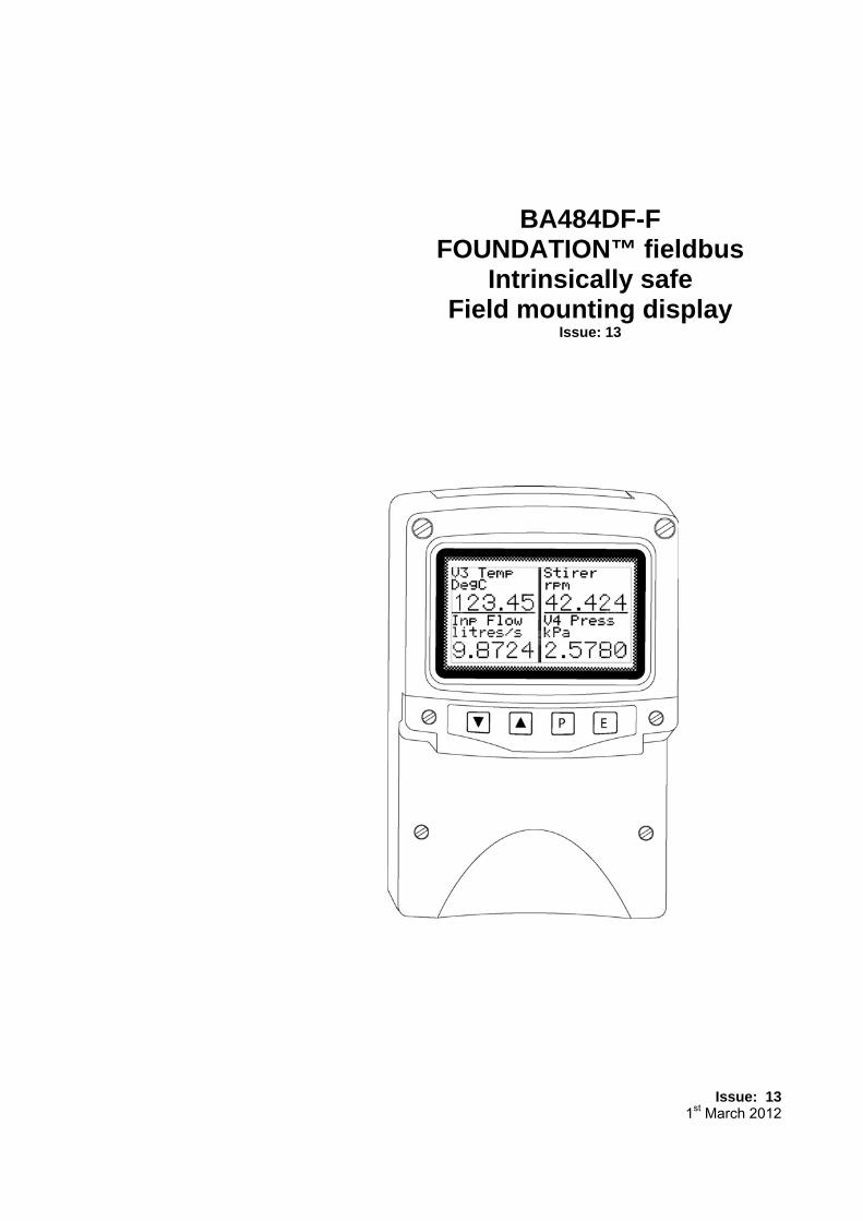
BA484DF-FFOUNDATION™ fieldbus
Intrinsically safeField mounting display
Issue: 13
2
1. Description1.1 Documentation1.2 Version 2.3 firmware
2. Operation2.1 Controls
3. Intrinsic Safety Certification3.1 ATEX certificate3.2 Zones, gas groups and T rating3.3 Fieldbus connection3.4 External switches3.5 Alarm outputs3.6 Certification label information
4. System Design for Hazardous Area4.1 FISCO Systems4.2 Non-FISCO Sysems4.3 External switches4.4 Alarm outputs
5. Installation5.1 Location5.2 Installation procedure5.3 EMC
6. Display & Alarm Configuration6.1 Default configuration
6.2 Accessing the display configurationmenus
6.3 Configurable functions6.3.1 Screens (Display format)6.3.2 Input Settings6.3.3 Tags6.3.4 Units6.3.5 Alarms
6.3.5.1 Alarm Summary6.3.5.2 Alarm Activation6.3.5.3 Alarm Output
6.3.6 Display6.3.6.1 Settings6.3.6.2 Quick Access6.3.6.3 Access Code6.3.6.4 Status Text6.3.6.5 Last Input
6.3.7 Keys6.3.8 Code6.3.9 Unit Info6.3.10 Defaults
6.3.10.1 Display Defaults6.3.10.2 Interface Board Default6.3.10.3 Revisions 1 and 2
6.4 Quick Access Menu
7. Programming (Removed from edition 12)
8. Maintenance8.1 Fault finding during commissioning8.2 Fault finding after commissioning8.3 Servicing8.4 Routine maintenance8.5 Guarantee8.6 Customer comments
9. Accessories9.1 Tag plate9.2 Pipe mounting kits9.3 FOUNDATION™ fieldbus Interface
Guide.
10. Index
Appendix 1ATEX dust certification
Appendix 2FM Approval for use in the USA
Appendix 3IECEx certification
CONTENTS
The BA484DF-F is CE marked to show compliance with theEuropean Explosive Atmospheres Directive 94/9/EC
and the European EMC Directive 2004/108/EC
3
1. DESCRIPTIONThe BA484DF-F display is an intrinsically safeinstrument that can simultaneously display up toeight FOUNDATION™ fieldbus process variables,together with their units of measurement and taginformation. The instrument is bus powered so noadditional power supply is required.
The instrument’s communication protocol is shownon a label inside the terminal cover. The ‘-F’ ordercode suffix also indicates the protocol but is notshown on the instrument certification label. Thereis an alternative version of the fieldbus display,order code BA484DF-P for use on PROFIBUS PAnetworks.
The BA484DF-F FOUNDATION™ fieldbus displaymay be ordered, or configured on-site, withalternative function blocks allowing use with mostFOUNDATION™ fieldbus hosts.
Revision 1One Multiple Analogue Output(1 x MAO)
Revision 2Two Input Selectors(2 x IS)
The required Device Description files, which maybe downloaded from either the FieldbusFoundation or the BEKA web sites, depend uponwhich BA484DF-F FOUNDATION™ fieldbusdisplay revision is selected.
Eleven selectable standard display formats enableone, two, three, four or eight process variables,some with bargraphs to be displayed on onescreen.
The BA484DF-F FOUNDATION™ fieldbus displaycan be supplied with six optional alarm outputs thatmay be linked to any of the displayed fieldbusvariables. These alarm outputs are locallyactivated from the fieldbus variables and areconfigured via the instrument menus and pushbuttons. They can not be controlled via thefieldbus..
The instrument has been issued with an EC-TypeExamination Certificate by Notified Body IntertekTesting and Certification Ltd for gas and dustatmospheres which has been used to confirmcompliance with the European PotentiallyExplosive Atmospheres Directive 94/9/EC.
For use in the USA the instrument has intrinsicsafety and nonincendive FM Approval – seeAppendix 2, plus IECEx intrinsic safety approval forinternational applications – see Appendix 3.
Housed in a robust IP66 glass reinforced polyester(GRP) enclosure with a toughened glass window,the BA484DF-F FOUNDATION™ fieldbus displayis surface mounting, or may be pipe mounted usingone of the accessory kits.
1.1 DocumentationThis instruction manual describes system design,conditioning and installation of the BA484DF-FFOUNDATION™ fieldbus display. For detailedcommissioning information please refer to theFOUNDATION™ fieldbus Interface Guide that canbe downloaded from the BEKA websitewww.beka.co.uk
1.2 Version 2.3 firmwareThis manual describes the enhanced features ofBA484DF-F FOUNDATION™ fieldbus displaysemploying version 2.3 firmware that was releasedin April 2011 following an interim update to version2.0 in December 2005.
The new features include:
Standard screens increased to 11
Multiple bargraph limits added
Input scaling added
Selectable function blocks added:
Revision 1 1 x MAO (multiple analogue output)
or Revision 2,2 x IS (Input selector)
Option added to remove status text fromsingle variable screens.
Last variable parameter added to preventdisplay of unused inputs.
The instrument’s firmware version can beestablished using the ‘Unit Info’ function in themain configuration menu – see section 6.3.9 of thismanual.
BA484DF-F FOUNDATION™ fieldbus displaysemploying version 2.3 firmware are backwardscompatible with all earlier versions of theinstrument.
4
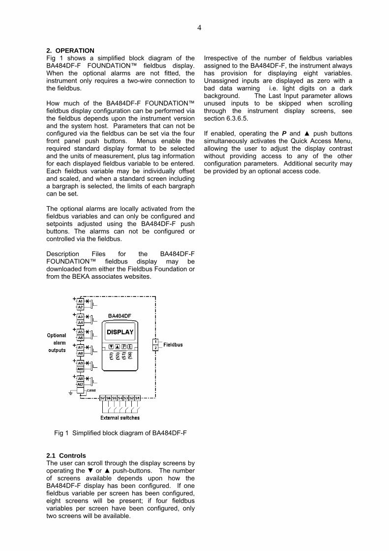
2. OPERATIONFig 1 shows a simplified block diagram of theBA484DF-F FOUNDATION™ fieldbus display.When the optional alarms are not fitted, theinstrument only requires a two-wire connection tothe fieldbus.
How much of the BA484DF-F FOUNDATION™fieldbus display configuration can be performed viathe fieldbus depends upon the instrument versionand the system host. Parameters that can not beconfigured via the fieldbus can be set via the fourfront panel push buttons. Menus enable therequired standard display format to be selectedand the units of measurement, plus tag informationfor each displayed fieldbus variable to be entered.Each fieldbus variable may be individually offsetand scaled, and when a standard screen includinga bargraph is selected, the limits of each bargraphcan be set.
The optional alarms are locally activated from thefieldbus variables and can only be configured andsetpoints adjusted using the BA484DF-F pushbuttons. The alarms can not be configured orcontrolled via the fieldbus.
Description Files for the BA484DF-FFOUNDATION™ fieldbus display may bedownloaded from either the Fieldbus Foundation orfrom the BEKA associates websites.
Fig 1 Simplified block diagram of BA484DF-F
2.1 ControlsThe user can scroll through the display screens byoperating the ▼ or ▲ push-buttons. The numberof screens available depends upon how theBA484DF-F display has been configured. If onefieldbus variable per screen has been configured,eight screens will be present; if four fieldbusvariables per screen have been configured, onlytwo screens will be available.
Irrespective of the number of fieldbus variablesassigned to the BA484DF-F, the instrument alwayshas provision for displaying eight variables.Unassigned inputs are displayed as zero with abad data warning i.e. light digits on a darkbackground. The Last Input parameter allowsunused inputs to be skipped when scrollingthrough the instrument display screens, seesection 6.3.6.5.
If enabled, operating the P and ▲ push buttonssimultaneously activates the Quick Access Menu,allowing the user to adjust the display contrastwithout providing access to any of the otherconfiguration parameters. Additional security maybe provided by an optional access code.
5
3. INTRINSIC SAFETY CERTIFICATION
3.1 ATEX certificateThe BA484DF-F has been issued with an EC-TypeExamination Certificate by Notified Body IntertekTesting and Certification (ITS) which has beenused to confirm compliance with the EuropeanATEX Directive 94/9/EC for Group II, Category 1,gas and dust atmospheres, Ex ia IIC T4. Theinstrument bears the Community Mark and, subjectto local codes of practice, may be installed in anyof the European Economic Area (EEA) membercountries. ATEX certificates are also acceptablefor installations in Switzerland.
This manual describes installations in explosivegas atmospheres which conform withIEC 60079-14 Electrical Installations design,selection and erection. When designing systemsfor installation outside the UK, the local Code ofPractice should be consulted.
For use in the presence of combustible dust,please refer to Appendix 1
3.2 Zones, gas groups and T ratingThe BA484DF-F has been issued with EC TypeExamination certificate ITS04ATEX22778confirming that it complies with the requirementsfor Group II Category 1 G Ex ia IIC T4 (Tamb –40to 60ºC). When connected to a suitable certifiedsystem the BA484DF-F may be installed in:
Zone 0 explosive gas air mixturecontinuously present.
Zone 1 explosive gas air mixturelikely to occur in normaloperation.
Zone 2 explosive gas air mixture notlikely to occur, and if it does willonly exist for a short time.
Be used with gases in groups:Group A propaneGroup B ethyleneGroup C hydrogen
Having a temperature classification of:
T1 450oC
T2 300oC
T3 200oC
T4 135oCAt an ambient temperature between –40 and+60ºC.
Note: the guaranteed operating temperature rangeof the Fieldbus Display is –20 to +60ºC
This allows the BA484DF-F FOUNDATION™fieldbus display to be installed in all Zones and tobe used with most common industrial gases.
3.3 Fieldbus connectionThe BA484DF-F Fieldbus Display is powered andcommunicates via the fieldbus, which is connectedto terminals 1 and 2. These terminals comply withthe Fieldbus Intrinsically Safe Concept (FISCO)defined in EN 60079 Part 27, which simplifiesintrinsic safety system design.
The BA484DF-F may also be connected to non-FISCO compliant fieldbus segments by using theentity concept to assess safety.
Terminals 1 and 2 of the BA484DF-FFOUNDATION™ fieldbus display are not polarisedand have the following safety parameters:
Ui = 17.5V dcIi = 380mA dcPi = 5.32W
For non-FISCO compliant segments, the safetyparameters of the power supply or isolatorpowering the fieldbus segment must be equal to orless than these figures.
The maximum equivalent capacitance andinductance at terminals 1 & 2 of the BA484DF-FFieldbus Display is:
Ci = 1nFLi = 8µH
To determine cable parameters for non-FISCOcompliant segments, the sum of Ci and Li of all thefield devices should be subtracted from themaximum cable parameters permitted by thedevice powering the fieldbus segment.
3.4 External switchesFor applications requiring operator inputs to bemade by large industrial push buttons, terminalsS1 to S7 facilitate external switches to beconnected to the BA484DF-F. When externalswitches are connected, the BA484DF-F may beconfigured so that the front panel push buttonscontinue to function or are disabled.
6
Terminals S1 to S7 have the following combinedoutput safety parameters:
Uo = 14.7V dcIo = 146.7mA dcPo = 0.58W
The switches and associated wiring connected tothe terminals must comply with the requirementsfor simple apparatus. i.e. the switch must bemechanically activated and have IP20 protection,and both the switch and the wiring must becapable of withstanding a 500V rms insulation testto earth for one minute. Most industrial pushbuttons and wiring satisfy these requirements.
The input safety parameters of terminals S1 to S7are zero, therefore only mechnically activatedswitches or intrinsically safe relays may beconnected.
The total maximum permitted cable parameters forall the cables connected to terminals S1 to S7 in aIIC hydrogen gas must be less than:
Co = 0.22µFLo = 0.26mH
Although these parameters are not restrictive, forreliable operation it is recommended that thecables between the fieldbus display and theexternal switch is less than 5m long.
3.5 Alarm outputsEach of the six optional alarm outputs is a separategalvanically isolated, solid state, single pole switch.The EC-Type Examination Certificate specifies thatunder fault conditions the voltage, current andpower at each switch output will not exceed thosespecified for simple apparatus in Clause 5.7 ofEN 60079-11. This allows each of the BA484DF-Falarm outputs to be connected to any intrinsicallysafe circuit protected by a certified Zener barrier orgalvanic isolator providing that the outputparameters of each circuit are less than:
Uo = 28V dcIo = 200mAPo = 0.84W
The maximum equivalent capacitance andinductance of each BA484DF-F alarm output is:
Ci = 40nFLi = 20µH
To determine the maximum permissible cableparameters, Ci and Li must be subtracted from themaximum cable capacitance and inductancespecified by the system certificate of the circuitconnected to the switch.
3.6 Certification Label InformationThe certification label is fitted in a recess on thetop outer surface of the enclosure. It shows theATEX certification information, a statement that theinstrument is a FISCO Field Device, plus BEKAassociates name and location. Non-Europeancertification information may also be included.The instrument serial number and year ofmanufacture are recorded on a separate labelinside the terminal compartment.
4. SYSTEM DESIGN FOR HAZARDOUS AREAS
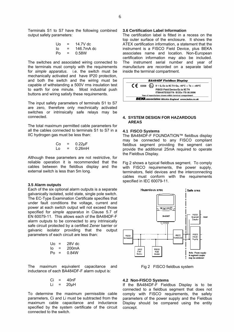
4.1 FISCO SystemsThe BA484DF-F FOUNDATION™ fieldbus displaymay be connected to any FISCO compliantfieldbus segment providing the segment canprovide the additional 25mA required to operatethe Fieldbus Display.
Fig 2 shows a typical fieldbus segment. To complywith FISCO requirements, the power supply,terminators, field devices and the interconnectingcables must conform with the requirementsspecified in IEC 60079-11.
Fig 2 FISCO fieldbus system
4.2 Non-FISCO SystemsIf the BA484DF-F Fieldbus Display is to beconnected to a fieldbus segment that does notcomply with FISCO requirements, the safetyparameters of the power supply and the FieldbusDisplay should be compared using the entityconcept.
7
The maximum output safety parameters of thedevice powering the fieldbus segment must beequal to, or less than, the input safety parametersof terminals 1 & 2 of the BA484DF-F FieldbusDisplay, namely:
Ui = 17.5V dcIi = 380mA dcPi = 5.32W
The maximum permitted cable parameters for thefieldbus segment must be reduced by theequivalent internal capacitance Ci and inductanceLi of the BA484DF-F. The BA484DF-F equivalentcapacitance and inductance are very small andmake little practical difference.
Ci = 1nFLi = 8µH
4.3 External switchesFor applications requiring operator inputs to bemade by large industrial push buttons, terminalsS1 to S7 allow up to six external switches to beconnected to the Fieldbus Display. When externalswitches are connected, the front panel pushbuttons may be operated in parallel or disabled –see section 6.3.7
For installation in a hazardous area the switchesand associated wiring must comply with therequirements for simple apparatus. i.e. the switchmust be mechanically activated and have IP20protection, and both the switch and the wiring mustbe capable of withstanding a 500V rms insulationtest to earth for one minute. Most industrial pushbuttons and wiring satisfy these requirements.
Although the allowable cable parameters are large,it is recommended that the cables are less than 5mlong.
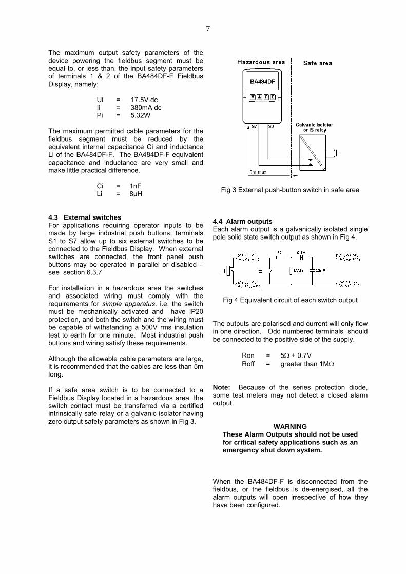
If a safe area switch is to be connected to aFieldbus Display located in a hazardous area, theswitch contact must be transferred via a certifiedintrinsically safe relay or a galvanic isolator havingzero output safety parameters as shown in Fig 3.
Fig 3 External push-button switch in safe area
4.4 Alarm outputsEach alarm output is a galvanically isolated singlepole solid state switch output as shown in Fig 4.
Fig 4 Equivalent circuit of each switch output
The outputs are polarised and current will only flowin one direction. Odd numbered terminals shouldbe connected to the positive side of the supply.
Ron = 5 + 0.7VRoff = greater than 1M
Note: Because of the series protection diode,some test meters may not detect a closed alarmoutput.
WARNINGThese Alarm Outputs should not be usedfor critical safety applications such as anemergency shut down system.
When the BA484DF-F is disconnected from thefieldbus, or the fieldbus is de-energised, all thealarm outputs will open irrespective of how theyhave been configured.
8
5. INSTALLATION
5.1 LocationThe BA484DF-F FOUNDATION™ fieldbus displayis housed in a robust IP66 glass reinforcedpolyester (GRP) enclosure incorporating anarmoured glass window and stainless steel fittings.It is suitable for exterior mounting in most industrialenvironments, including off-shore and waste watertreatment installations. Please consult BEKAassociates if high vibration is anticipated.
The BA484DF-F enclosure is surface mounting.Accessory kits described in sections 9.2 of thismanual enable the instrument to be mounted ontoa vertical or horizontal pipe.
The field terminals and the two mounting holes arelocated in a separate compartment with a sealedcover allowing the instrument to be installedwithout exposing the display assembly.
The BA484DF-F earth terminal is connected to thecarbon loaded GRP case. If the case is not boltedto a post or structure connected to the plantpotential equalising network, the instrument’s earthterminal should be connected to the potentialequalising network as recommended inEN 60079-14.
The BA484DF-F enclosure is supplied with abonding plate to ensure electrical continuitybetween the three conduit / cable entries.
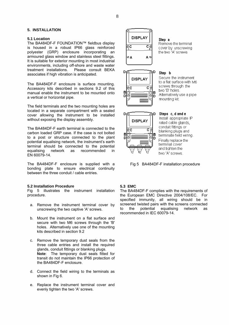
5.2 Installation ProcedureFig 5 illustrates the instrument installationprocedure.
a. Remove the instrument terminal cover byunscrewing the two captive 'A' screws.
b. Mount the instrument on a flat surface andsecure with two M6 screws through the 'B'holes. Alternatively use one of the mountingkits described in section 9.2
c. Remove the temporary dust seals from thethree cable entries and install the requiredglands, conduit fittings or blanking plugs.Note: The temporary dust seals fitted fortransit do not maintain the IP66 protection ofthe BA484DF-F enclosure.
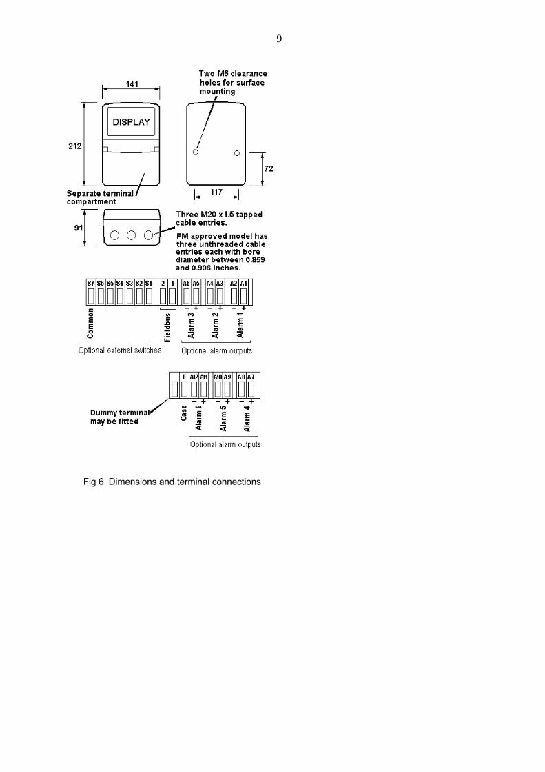
d. Connect the field wiring to the terminals asshown in Fig 6.
e. Replace the instrument terminal cover andevenly tighten the two 'A' screws.
Fig 5 BA484DF-F installation procedure
5.3 EMCThe BA484DF-F complies with the requirements ofthe European EMC Directive 2004/108/EC. Forspecified immunity, all wiring should be inscreened twisted pairs with the screens connectedto the potential equalising network asrecommended in IEC 60079-14.
9
Fig 6 Dimensions and terminal connections
10
6. DISPLAY & ALARM CONFIGURATIONIn addition to loading the BA484DF-FFOUNDATION™ fieldbus display DeviceDescription files onto the system host and definingup to eight fieldbus variables that are to bedisplayed, the instrument display and alarms, iffitted, have to be configured. How much of thisconfiguration can be performed via the fieldbusdepends upon the instrument version and thesystem host. Parameters that can not beconfigured via the fieldbus should be configuredvia the instrument push buttons and the easy touse menu shown in Fig 7. The optional alarmscan only be configured via the instrument pushbuttons.
When navigating through the configuration menu,the push button(s) should be held until the requiredscreen is displayed.
6.1 Default configurationUnless otherwise requested at the time of ordering,BA484DF-F FOUNDATION™ Fieldbus Displayswill be supplied configured as follows:
Keys BothDisplay brightness 100%Display contrast 50%Quick access menu OnQuick access menu code 0000Configuration menu access code. 0000Screen Single variableNumber format AutoAll alarms DisabledAlarm activation Good data onlyAlarm outputs N/CBargraph
Low 0High 100
Input scalingZero offset 0Gain factor 1
Status text OnLast input 8Revision Revision 2
(2 x IS function blocks)
6.2 Accessing the display configuration menusThroughout this manual push buttons are shown initalics e.g. P E ▼ ▲ and legends displayed bythe instrument are shown within inverted commase.g. 'Enter Access Code'.
Operating the P and E push buttonssimultaneously accesses the display configurationmenu. If the BA484DF-F is not protected by anaccess code the main menu will be displayed. Ifan access code other than the default code 0000has already been entered, the BA484DF-F willrequest that the access code be entered.
Using the ▼ or ▲ button set the first digit of thecode which will be flashing. Pressing P willtransfer control to the next digit, which should beadjusted in the same way. When all four digitshave been set, pressing the E button will enter theaccess code. If the code is correct the mainmenu will be displayed, if the code is incorrect‘Invalid Code’ will be displayed.
When entering an access code, timeout will occurand the instrument will automatically return to theoperating mode ten seconds after a push buttonwas last operated. In all other menus, timeoutoccurs after sixty seconds.
The structure of the display configuration menu isshown in Fig 7. Navigation is achieved byhighlighting the required function using the ▼ and▲ buttons and then operating the P button todisplay the selected function sub-menu, from whicha further selection or adjustment may be made.Operating the E button moves the display back upone level.
A flashing highlight indicates that an option oralphanumeric character may be selected using the▼ and ▲ buttons and entered using the E button.If only one entry or adjustment can be made in asub-menu, the display will automatically move upone menu level when the adjustment is entered. Ifmore than one adjustment can be made in a sub-menu, the highlight may be moved to the secondvariable using the ▼or ▲ button after the firstsetting has been entered. Operating the P buttonallows the second variable to be adjusted.
When multiple numeric or alpha characters areadjusted e.g. an alarm setpoint or a tag legend, theadjustment is made one digit at a time using the▼and ▲ buttons. After the first flashing digit hasbeen set as required, the flashing highlight can bemoved to the next digit by operating the P button.When all digits have been set, operating the Ebutton will enter the setting.
Following completion of the instrumentconfiguration, the E button should be operated tostep the display back to the main menu. One moreoperation of the E button will then return theBA484DF-F to the operating mode.
11
6.3 Configurable functionsThis section provides an explanation of eachconfigurable function and should be read inconjunction with Fig 7.
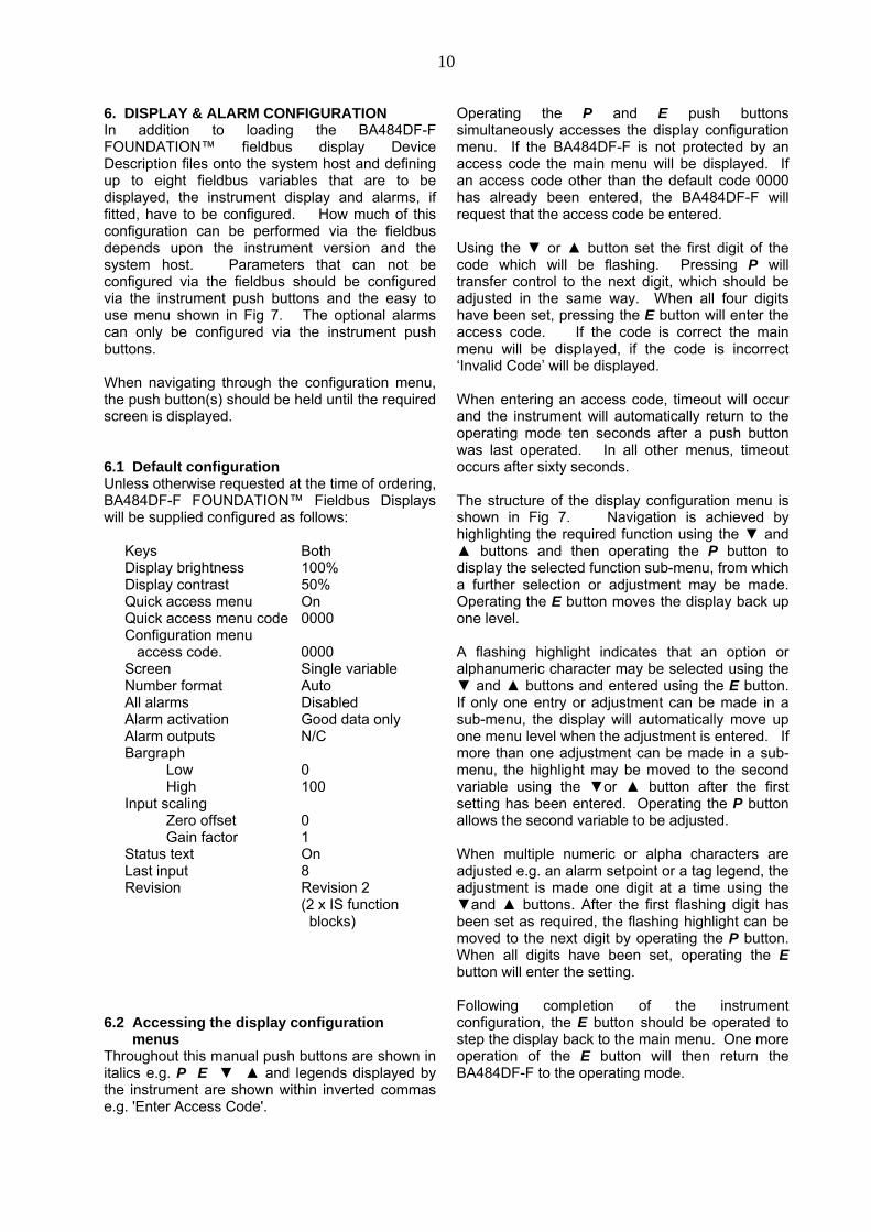
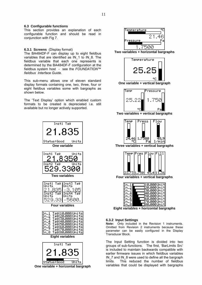
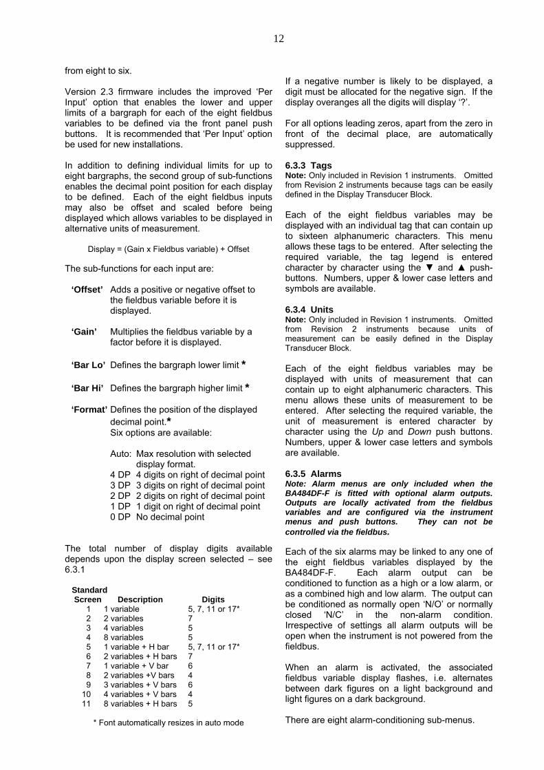
6.3.1 Screens (Display format)The BA484DF-F can display up to eight fieldbusvariables that are identified as IN_1 to IN_8. Thefieldbus variable that each one represents isdetermined by the BA484DF-F configuration at thefieldbus system host - see the FOUNDATION™fieldbus Interface Guide.
This sub-menu allows one of eleven standarddisplay formats containing one, two, three, four oreight fieldbus variables some with bargraphs asshown below.
The ‘Text Display’ option which enabled customformats to be created is depreciated i.e. stillavailable but no longer actively supported.
One variable
Two variables
Four variables
Eight variables
One variable + horizontal bargraph
Two variables + horizontal bargraphs
One variable + vertical bargraph
Two variables + vertical bargraphs
Three variables + vertical bargraphs
Four variables + vertical bargraphs
Eight variables + horizontal bargraphs
6.3.2 Input SettingsNote: Only included in the Revision 1 instruments.Omitted from Revision 2 instruments because theseparameter can be easily configured in the DisplayTransducer Block.
The Input Setting function is divided into twogroups of sub-functions. The first, ‘BarLimits Src’is included to maintain backwards compatible withearlier firmware issues in which fieldbus variablesIN_7 and IN_8 were used to define all the bargraphlimits. This reduced the number of fieldbusvariables that could be displayed with bargraphs
12
from eight to six.
Version 2.3 firmware includes the improved ‘PerInput’ option that enables the lower and upperlimits of a bargraph for each of the eight fieldbusvariables to be defined via the front panel pushbuttons. It is recommended that ‘Per Input’ optionbe used for new installations.
In addition to defining individual limits for up toeight bargraphs, the second group of sub-functionsenables the decimal point position for each displayto be defined. Each of the eight fieldbus inputsmay also be offset and scaled before beingdisplayed which allows variables to be displayed inalternative units of measurement.
Display = (Gain x Fieldbus variable) + Offset
The sub-functions for each input are:
‘Offset’ Adds a positive or negative offset tothe fieldbus variable before it isdisplayed.
‘Gain’ Multiplies the fieldbus variable by afactor before it is displayed.
‘Bar Lo’ Defines the bargraph lower limit *
‘Bar Hi’ Defines the bargraph higher limit *
‘Format’ Defines the position of the displayeddecimal point.*Six options are available:
Auto: Max resolution with selecteddisplay format.
4 DP 4 digits on right of decimal point3 DP 3 digits on right of decimal point2 DP 2 digits on right of decimal point1 DP 1 digit on right of decimal point0 DP No decimal point
The total number of display digits availabledepends upon the display screen selected – see6.3.1
Standard Screen Description Digits
1 1 variable 5, 7, 11 or 17*2 2 variables 73 4 variables 54 8 variables 55 1 variable + H bar 5, 7, 11 or 17*6 2 variables + H bars 77 1 variable + V bar 68 2 variables +V bars 49 3 variables + V bars 6
10 4 variables + V bars 411 8 variables + H bars 5
* Font automatically resizes in auto mode
If a negative number is likely to be displayed, adigit must be allocated for the negative sign. If thedisplay overanges all the digits will display ‘?’.
For all options leading zeros, apart from the zero infront of the decimal place, are automaticallysuppressed.
6.3.3 TagsNote: Only included in Revision 1 instruments. Omittedfrom Revision 2 instruments because tags can be easilydefined in the Display Transducer Block.
Each of the eight fieldbus variables may bedisplayed with an individual tag that can contain upto sixteen alphanumeric characters. This menuallows these tags to be entered. After selecting therequired variable, the tag legend is enteredcharacter by character using the ▼ and ▲ push-buttons. Numbers, upper & lower case letters andsymbols are available.
6.3.4 UnitsNote: Only included in Revision 1 instruments. Omittedfrom Revision 2 instruments because units ofmeasurement can be easily defined in the DisplayTransducer Block.
Each of the eight fieldbus variables may bedisplayed with units of measurement that cancontain up to eight alphanumeric characters. Thismenu allows these units of measurement to beentered. After selecting the required variable, theunit of measurement is entered character bycharacter using the Up and Down push buttons.Numbers, upper & lower case letters and symbolsare available.
6.3.5 AlarmsNote: Alarm menus are only included when theBA484DF-F is fitted with optional alarm outputs.Outputs are locally activated from the fieldbusvariables and are configured via the instrumentmenus and push buttons. They can not becontrolled via the fieldbus.
Each of the six alarms may be linked to any one ofthe eight fieldbus variables displayed by theBA484DF-F. Each alarm output can beconditioned to function as a high or a low alarm, oras a combined high and low alarm. The output canbe conditioned as normally open ‘N/O’ or normallyclosed ‘N/C’ in the non-alarm condition.Irrespective of settings all alarm outputs will beopen when the instrument is not powered from thefieldbus.
When an alarm is activated, the associatedfieldbus variable display flashes, i.e. alternatesbetween dark figures on a light background andlight figures on a dark background.
There are eight alarm-conditioning sub-menus.
13
6.3.5.1 Alarm SummaryShows to which fieldbus variable each alarm islinked and how each alarm has been conditioned.i.e. high, low, or combined high & low alarm withnormally open or closed output. No adjustmentscan be made via this sub-menu.
6.3.5.2 Alarm ActivationFieldbus variables that have not been validated aredisplayed with dark characters on a lightbackground, and some screen formats also containa status indication. This sub-menu allows thealarm outputs to be conditioned so that they onlyoperate with validated fieldbus data, or to operateirrespective of data validity.
6.3.5.3 Alarm OutputThere is a separate sub-menu for each of the sixalarm outputs; these link the alarm to one of thedisplayed fieldbus variables and define the alarmfunction and the setpoints.
To link the alarm to a displayed variable, positionthe highlight over the ‘IN_n’ field, press P andusing the ▼ or ▲ button select the required inputsource. Enter the selection by pressing the Ebutton.
Each alarm output can be N/O or N/C in the non-alarm condition. To change the setting, position thehighlight over the ‘N/O or N/C’ field, press P anduse the ▼ or ▲ button to toggle the setting. Enterthe selection by pressing the E button.
Each alarm output has three functions that can beindependently enabled to condition the output as alow or high alarm, or as a combined low and highalarm, either with or without hysteresis.
The required functions can be individually enabledby positioning the highlight over the Enb/Dis(Enabled/Disabled) column, pressing P andtoggling the function to the required state, thenentering the selection by pressing the E button.
Alarm setpoints are entered digit by digit. Placethe highlight over the setpoint to be adjusted andpress P; the flashing digit to be adjusted may thenbe selected by again pressing P. When all thedigits have been adjusted, operating the E buttonenters the value and moves the menu up one level.
The function of all alarms may be reviewed fromthe alarm summary menu - see 6.3.5.1.
6.3.6 Display6.3.6.1 SettingsThe backlight brilliance and display contrast areadjustable from this sub-menu.
6.3.6.2 Quick AccessThis sub-menu enables the Quick Access Menuwhich is described in sections 2.1 and 6.4 Whenenabled, an operator can adjust the displaycontrast and backlight brilliance without havingaccess to any other conditioning menus.
6.3.6.3 Access CodeDefines a four digit alphanumeric code that mustbe entered to gain access to the Quick AccessMenu. Alpha characters are case sensitive.Default code 0000 allows direct access without acode.
6.3.6.4 Status TextThe two single variable screens 1 and 4 will showthe status of the FOUNDATION™ fieldbus variableas ‘Good’ or ‘Bad’ if the Status Text function isactivated.
6.3.6.5 Last InputThis function allows the maximum number ofFOUNDATION™ fieldbus variables to be definedso that unused inputs are skipped when the displayis scrolled in the operating mode.
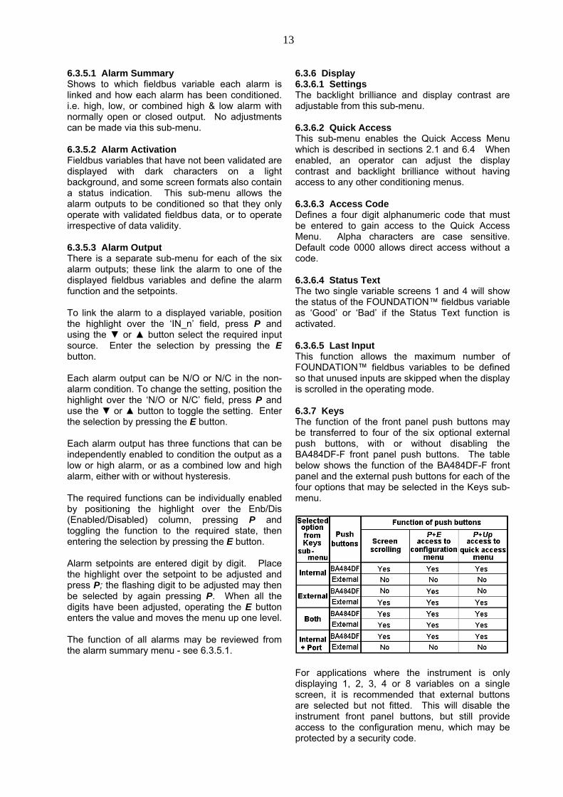
6.3.7 KeysThe function of the front panel push buttons maybe transferred to four of the six optional externalpush buttons, with or without disabling theBA484DF-F front panel push buttons. The tablebelow shows the function of the BA484DF-F frontpanel and the external push buttons for each of thefour options that may be selected in the Keys sub-menu.
For applications where the instrument is onlydisplaying 1, 2, 3, 4 or 8 variables on a singlescreen, it is recommended that external buttonsare selected but not fitted. This will disable theinstrument front panel buttons, but still provideaccess to the configuration menu, which may beprotected by a security code.
14
6.3.8 CodeDefines the four digit alphanumeric code that mustbe entered to gain access to the instrumentconfiguration menus. Alpha characters are casesensitive. Default code 0000 allows direct accesswithout a code.
6.3.9 Unit InfoDisplays the instrument model number and thesoftware version.
6.3.10 DefaultsThis function enables the display and interfaceboard factory defaults to be restored. The functionblocks (Revision 1 or 2) should be selected to suitthe system host.
6.3.10.1 Display DefaultsThis function restores the display defaults definedin section 6.1.
CAUTIONExisting settings can not be recoveredafter this function has been used.
6.3.10.2 Interface Board DefaultsThis function restores the Fieldbus Interface Boardfactory defaults.
CAUTIONDo not use this function when theBA484DF-F is connected to anoperational fieldbus, as communicationwill be terminated.
6.3.10.3 Revisions 1 and 2Unless specified at the time of ordering, BA484DF-F FOUNDATION™ fieldbus displays will besupplied as Revision 2 instruments. i.e. two inputselector function blocks (2 x IS), but it can easilybe converted to a Revision 1 instrument using theDefault menu. i.e one multiple analogue outputfunction block (1 x MAO).
The BA484DF-F FOUNDATION™ fieldbus displayrevision should be chosen so that the fieldbusfunction blocks selected are supported by thesystem host.
To change the BA484DF-F FOUNDATION™fieldbus display revision, highlight the requiredrevision in the ‘Restore Defaults’ menu and followthe screen prompts until ‘Defaults Loaded Nowpower cycle the unit’ is displayed. To completethe installation remove the BA484DF-F powersupply for a few seconds, when power is restoredthe instrument will restart with the selectedrevision.
6.4 Quick Access MenuThe Quick Access Menu allows an operator toadjust the backlight brilliance and the displaycontrast without having access to the otherconfiguration parameters.
The quick access menu is accessed by operatingthe P and ▲push-buttons simultaneously. If theQuick Access Menu is not protected by an accesscode the contrast and brilliance controls will bedisplayed immediately. If an access code otherthan the default code 0000 has already beenentered, the BA484DF-F will request that theaccess code be entered.
The display backlight brilliance is adjusted usingthe ▼and ▲push buttons. Operating the P pushbutton will transfer control to the display contrastadjustment. When both are set as required,operating the E button will store both settings andreturn the instrument to the operating mode.

15
16
7. PROGRAMMINGThe ‘Text Display’ option which enabled customformats to be created is depreciated i.e. stillavailable but no longer actively supported.
8. MAINTENANCE
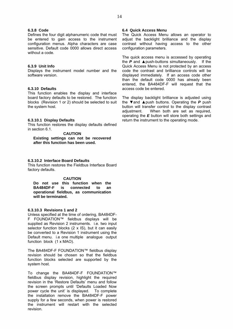
8.1 Fault finding during commissioningIf a BA484DF-F FOUNDATION™ fieldbus displayfails to function during commissioning the followingprocedure should be followed:
Symptom Cause Check:No Display Fieldbus not
powered9 to 17.5Vbetween
terminals 1 & 2.
No variables Fieldbus notconfigured
Instrumentconfiguration at
hostWrong variable
displayedWrong screen
selectedOther screens byoperating Up or
Down buttonDisplay shows
‘?????’Display
overrangeNumber format
see section 6.3.2No backlight Brilliance turned
downSetting in display
menuLow or excessive
contrastIncorrect contrast
settingSetting in display
menuDisplayedvariable isinverted
i.e. light digits ondark background
Variable has‘bad’ status
Configurationand instrument
supplyingvariable
Displayedvariable isflashing
Associated alarmhas beenactivated
Setpoints
Bargraph onstandard displayformat is shown
dotted
Displayedfieldbus variable
is outsidebargraph limits or
data is ‘bad’
Bargraph limitssee section 6.3.2
8.2 Fault finding after commissioning
ENSURE PLANT SAFETY BEFORESTARTING MAINTENANCE
Live maintenance is permitted onintrinsically safe equipment installed in ahazardous area, but only certified testequipment should be used unless a gasclearance certificate is available.
If a BA484DF-F fails after it has been functioningcorrectly, the table shown in section 8.1 may helpto identify the cause of the failure.
If this procedure does not reveal the cause of thefault, it is recommended that the instrument isreplaced.
8.3 ServicingWe recommend that faulty BA484DF-FFOUNDATION™ fieldbus displays are returned toBEKA associates or to our local agent for repair.
8.4 Routine maintenanceThe mechanical and electrical condition of theinstrument should be regularly checked. Initiallyannual inspections are recommended, althoughthe inspection frequency should be adjusted to suitthe environmental conditions.
8.5 GuaranteeInstruments which fail within the guarantee periodshould be returned to BEKA associates or our localagent. It is helpful if a brief description of the faultsymptoms is provided.
8.6 Customer commentsBEKA associates is always pleased to receivecomments from customers about our products andservices. All communications are acknowledgedand whenever possible, suggestions areimplemented.

17
9. ACCESSORIES
9.1 Tag plateThe BA484DF-F FOUNDATION™ fieldbus displaycan be supplied with a blank or custom engravedstainless steel plate secured by two screws to theside of the instrument enclosure. This plate canaccommodate:
1 row of 9 alphanumeric characters 10mm high
or 1 row of 11 alphanumeric characters 7mm high
or 2 rows of 18 alphanumeric characters 5mm high
9.2 Pipe mounting kitsTwo pipe mounting kits are available for securingthe BA484DF-F to a horizontal or vertical pipe.
BA392D Stainless steel bracket secured by twoworm drive hose clips for 60 to 80mmoutside diameter pipes.
BA393 Heavy duty stainless steel bracketsecured by a single 'V' bolt. Will clampto any pipe with an outside diameterbetween 40 and 80mm.
9.3 FOUNDATION™ fieldbus Interface GuideThe BEKA FOUNDATION™ fieldbus InterfaceGuide which may be downloaded from the BEKAweb site at www.beka.co.uk contains conditioninginformation for all BEKA FOUNDATION™ fieldbusproducts.
18
10. INDEX
Subject Section
Alarms 6.3.5Activation 6.3.5.2Output 3.5; 6.3.5.3; 4.4Summary 6.3.5.1
ATEX Directive 3.1Dust certification Appendix 1
Backlight 6.3.6.1Bargraph limits 6.3.2
CertificatesEC-Type Examination 3.1Label 3.6
Configuration menu Fig 7Controls 2.1Code 6.3.8
Decimal Points 6.3.2Default settings 6.1; 6.3.10Display 6.3.6
Access code 6.3.6.3Settings 6.3.6.1Quick access 6.3.6.2; 6.4
Dust certification Appendix 1; 2; 3
EMC 5.3External switches 3.4; 4.3; 6.3.7Fault finding
During commissioning 8.1After commissioning 8.2
FieldbusConnection 3.3Foundation 1; 2Guide 9.4Revisions 1 & 2 6.3.10.3
FISCO 3.3; 4.1FM Approval Appendix 2Function Blocks 1; 6.3.10.3
Gas groups 3.2Guarantee 8.5
IECEx Certification Appendix 3Input scaling 6.3.12Installation 5Intrinsic safety 3; Appendix 1; 2; 3
Keys 6.3.7
Last input 6.3.6.5Location 5.1;
Appendix 1; 2; 3
Maintenance 8.Routine 8.4
Subject Section
Notified Body 1; 3.1Number Format 6.3.2
Pipe mounting kits 9.2 Profibus PA 1
Quick access menu 6.3.6.2; 6.4
Revisions 1 & 2 1; 6.3.10.3
Servicing 8.3Screens (display format) 6.3.1Status text 6.3.6.4
Tags 6.3.3Tag plate 9.1T rating 3.2Terminal numbers Fig 6
Units (of measurement) 6.3.4Unit Info (firmware version) 6.3.9
Zones 3.2; Appendix 1; 2; 3
19
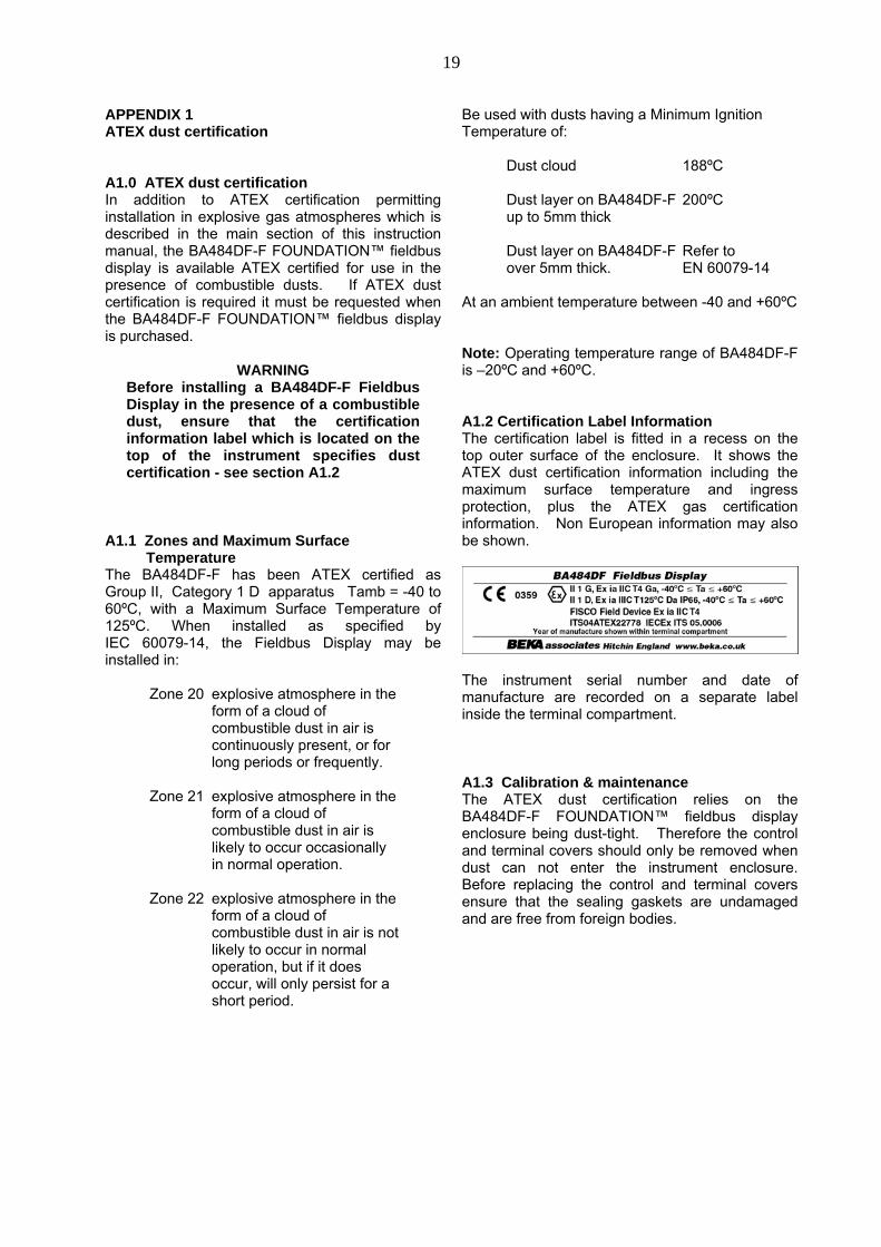
APPENDIX 1ATEX dust certification
A1.0 ATEX dust certificationIn addition to ATEX certification permittinginstallation in explosive gas atmospheres which isdescribed in the main section of this instructionmanual, the BA484DF-F FOUNDATION™ fieldbusdisplay is available ATEX certified for use in thepresence of combustible dusts. If ATEX dustcertification is required it must be requested whenthe BA484DF-F FOUNDATION™ fieldbus displayis purchased.
WARNINGBefore installing a BA484DF-F FieldbusDisplay in the presence of a combustibledust, ensure that the certificationinformation label which is located on thetop of the instrument specifies dustcertification - see section A1.2
A1.1 Zones and Maximum Surface TemperatureThe BA484DF-F has been ATEX certified asGroup II, Category 1 D apparatus Tamb = -40 to60ºC, with a Maximum Surface Temperature of125ºC. When installed as specified byIEC 60079-14, the Fieldbus Display may beinstalled in:
Zone 20 explosive atmosphere in theform of a cloud ofcombustible dust in air iscontinuously present, or forlong periods or frequently.
Zone 21 explosive atmosphere in theform of a cloud ofcombustible dust in air islikely to occur occasionallyin normal operation.
Zone 22 explosive atmosphere in theform of a cloud ofcombustible dust in air is notlikely to occur in normaloperation, but if it doesoccur, will only persist for ashort period.
Be used with dusts having a Minimum IgnitionTemperature of:
Dust cloud 188ºC
Dust layer on BA484DF-F 200ºCup to 5mm thick
Dust layer on BA484DF-F Refer toover 5mm thick. EN 60079-14
At an ambient temperature between -40 and +60ºC
Note: Operating temperature range of BA484DF-Fis –20ºC and +60ºC.
A1.2 Certification Label InformationThe certification label is fitted in a recess on thetop outer surface of the enclosure. It shows theATEX dust certification information including themaximum surface temperature and ingressprotection, plus the ATEX gas certificationinformation. Non European information may alsobe shown.
The instrument serial number and date ofmanufacture are recorded on a separate labelinside the terminal compartment.
A1.3 Calibration & maintenanceThe ATEX dust certification relies on theBA484DF-F FOUNDATION™ fieldbus displayenclosure being dust-tight. Therefore the controland terminal covers should only be removed whendust can not enter the instrument enclosure.Before replacing the control and terminal coversensure that the sealing gaskets are undamagedand are free from foreign bodies.

20
APPENDIX 2FM approval for use in the USA
A2.0 Factory Mutual ApprovalFor installations in the USA, the BA484DF-FFOUNDATION™ fieldbus display and optionalalarms have been approved intrinsically safe andnonincendive by FM Approvals, projectidentification 3022546. Copies of the Certificate ofCompliance are available from BEKA associates.
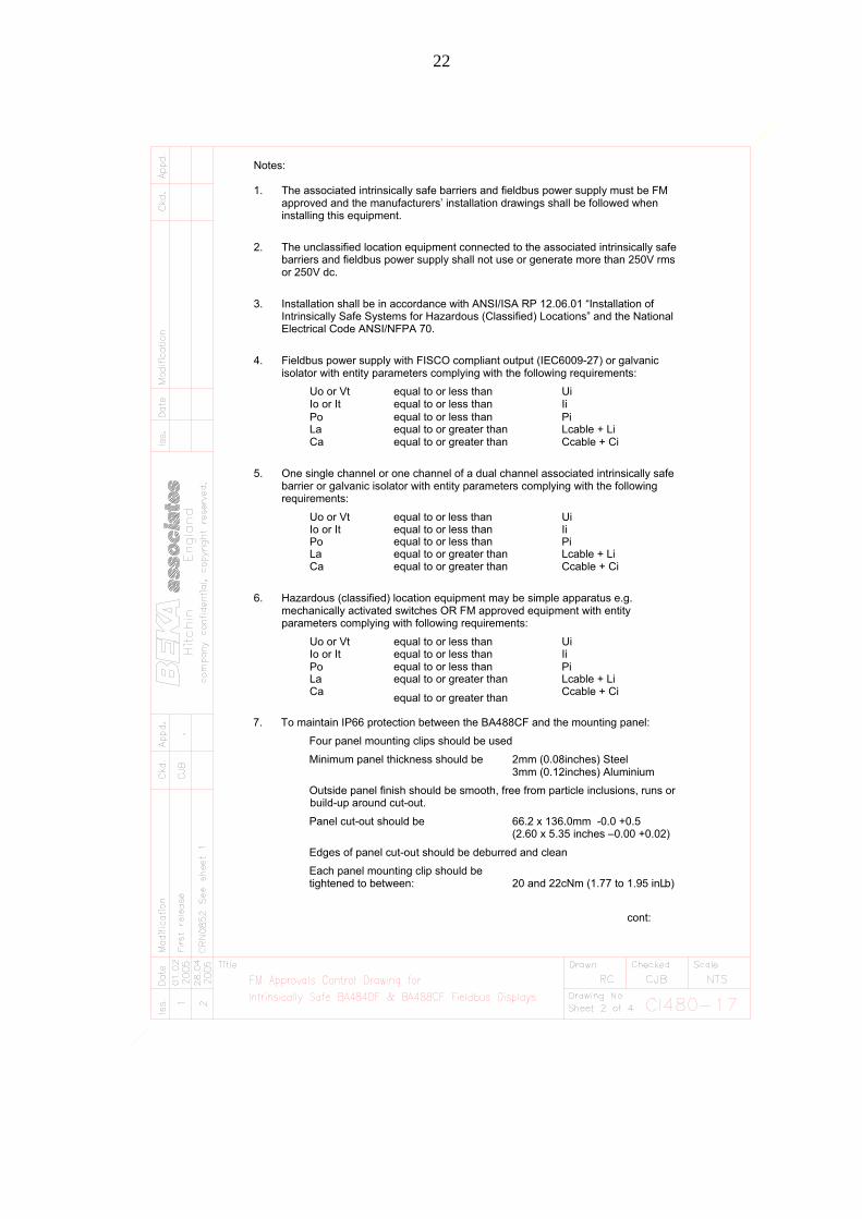
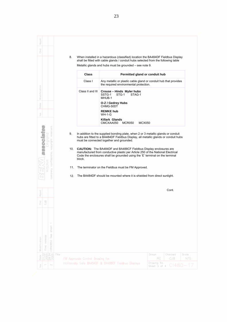
The FM Approved version of the BA484DF-FFieldbus Display is identical to the ATEX versionexcept the three M20 x 1,5 tapped cable entriesare replaced by three plain unthreaded 22.25mmdiameter entries. Approved hubs and glands arelisted in note 8 of Control Drawing CI480-17 andnote 7 of Control Drawing CI480-18. Thecertification label on the FM Approved versionincludes ATEX gas certification information so thatthe Fieldbus Display may be used in systemscovered by either authority.
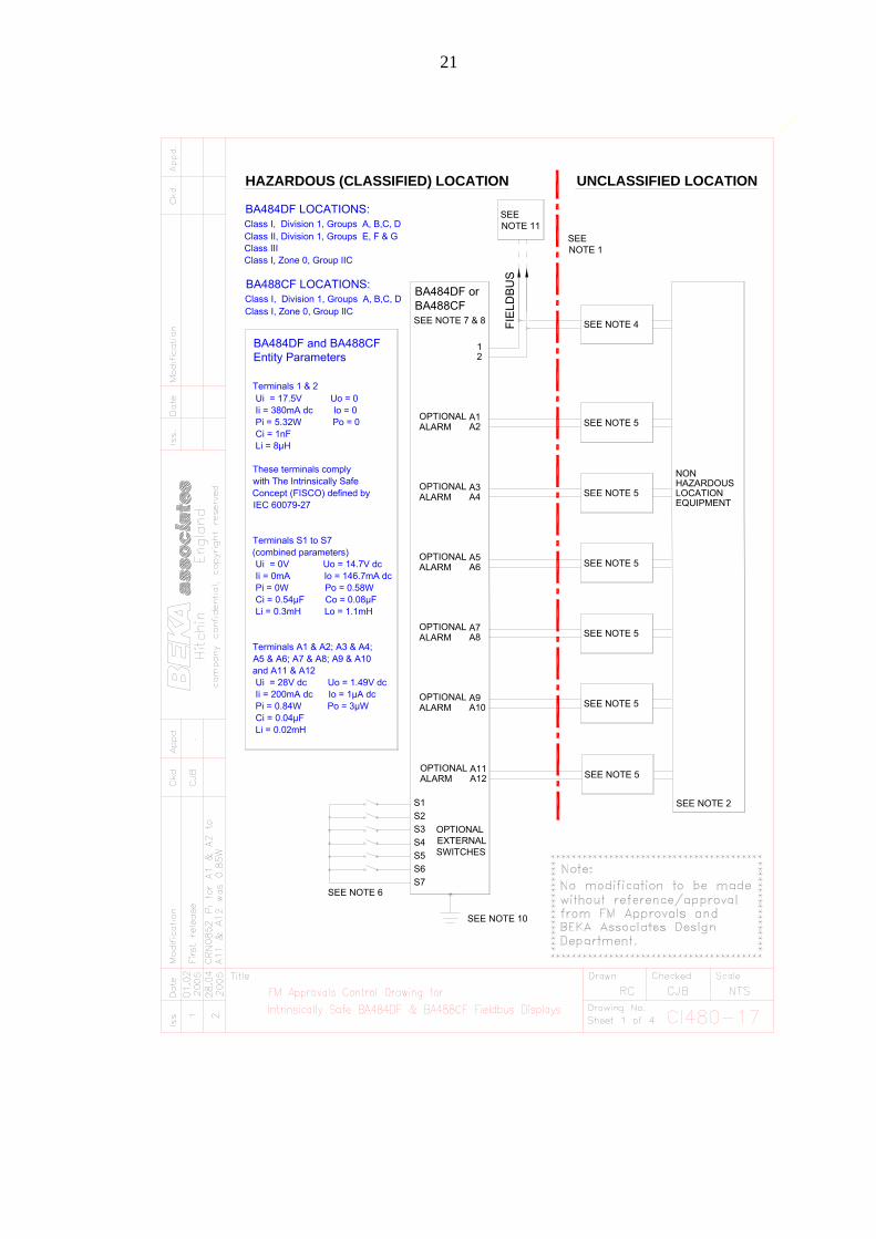
A2.1 Intrinsic safey approvalThe BA484DF-F is approved to the FM Class 3610intrinsic safety standard for use in indoor andoutdoor hazardous (classified) locations.Installations must comply with BEKA associatesControl Drawing CI480-17, which is attached tothis Appendix, ANSI/ISA RP12.06.01 ‘Installationof Intrinsically Safe Systems for Hazardous(Classified) Locations’ and with the NationalElectrical Code ANSI/NFPA70.
The BA484DF-F has a T4 rating at ambienttemperatures up to +60oC and may be used withthe following gases and dusts:
Intrinsic SafetyDivision 1 or 2
Class I Group A & B Group C Group D
Class II Group E, F & G
Class III
Zone 0, 1 or 2Class 1 Group IIC Group IIB Group IIA
The FM entity parameters are identical to theATEX parameters and, like the ATEX certification,confirm that terminals 1 & 2 of the BA484DF-Fcomply with the requirements for a FISCO FieldDevice specified in IEC60079-27. The intrinsicallysafe circuits shown in Figs 2 and 3 of this manualmay therefore be used for installations in the USA,providing the fieldbus power supply, terminators,Zener barriers and galvanic isolators are FMApproved and comply with BEKA associatesControl Drawing CI480-17. The FM Approval alsoallows the BA484DF-F to be connected to non-FISCO systems using the entity concept – seesection 4.2 of this manual.
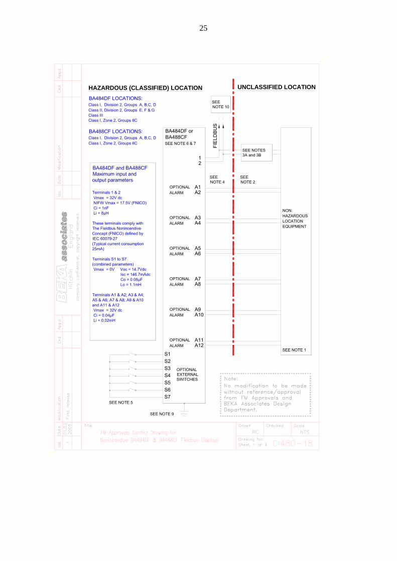
A2.2 Nonincendive approvalThe BA484DF-F FOUNDATION™ fieldbus displayis Class 3611 nonincendive approved by FactoryMutual allowing it to be installed in Division 2indoor and outdoor hazardous (classified) locationswithout the need for Zener barriers or galvanicisolators. Installations must comply with the BEKAassociates Control Drawing CI480-18, which isattached to this Appendix, and with the NationalElectrical Code ANSI/NFPA70.
The FM Nonincendive Approval also allows theinstrument to be connected to any FNICOcompliant fieldbus segment powered by FMApproved Associated Nonincendive Field WiringApparatus.
The BA484DF-F has a T4 rating at ambienttemperatures up to +60oC and may be used withthe following gases and dusts:
NonincendiveDivision 2
Class I Group A & B Group C Group D
Class II Groups E, F & G
Class III
Zone 2Class I Group IIC Group IIB Group IIA
21
HAZARDOUS (CLASSIFIED) LOCATION UNCLASSIFIED LOCATION
EQUIPMENTLOCATIONHAZARDOUSNON
SEE NOTE 2
SEE NOTE 5
SEE NOTE 5
SEE NOTE 5
SEE NOTE 5
SEE NOTE 5
SEE NOTE 5
A9ALARM
ALARM
OPTIONAL
OPTIONALA12A11
A10
BA484DF orBA488CFSEE NOTE 7 & 8
S7
BA484DF LOCATIONS:Class I, Division 1, Groups A, B,C, DClass II, Division 1, Groups E, F & GClass IIIClass I, Zone 0, Group IIC
BA488CF LOCATIONS:Class I, Division 1, Groups A, B,C, DClass I, Zone 0, Group IIC
SEE NOTE 1
BA484DF and BA488CFEntity Parameters
Terminals 1 & 2 Ui = 17.5V Uo = 0 Ii = 380mA dc Io = 0 Pi = 5.32W Po = 0 Ci = 1nF Li = 8µH
These terminals comply with The Intrinsically Safe Concept (FISCO) defined byIEC 60079-27
Terminals S1 to S7 (combined parameters) Ui = 0V Uo = 14.7V dc Ii = 0mA Io = 146.7mA dc Pi = 0W Po = 0.58W Ci = 0.54µF Co = 0.08µF Li = 0.3mH Lo = 1.1mH
Terminals A1 & A2; A3 & A4; A5 & A6; A7 & A8; A9 & A10 and A11 & A12 Ui = 28V dc Uo = 1.49V dc Ii = 200mA dc Io = 1µA dc Pi = 0.84W Po = 3µW Ci = 0.04µF Li = 0.02mH
A7OPTIONALALARM A8
A5OPTIONALALARM A6
A3OPTIONALALARM A4
A1OPTIONALALARM A2
S6
S5
S4
S3
S2
S1
SEE NOTE 6
OPTIONALEXTERNALSWITCHES
21
SEE NOTE 4FIE
LDB
US
SEE NOTE 10
SEE NOTE 11
22
Outside panel finish should be smooth, free from particle inclusions, runs or
To maintain IP66 protection between the BA488CF and the mounting panel:
20 and 22cNm (1.77 to 1.95 inL
(2.60 x 5.35 inches –0.00 +0.02)66.2 x 136.0mm -0.0 +0.5
3mm (0.12inches) Aluminium2mm (0.08inches) Steel
tightened to between:Each panel mounting clip should be
Edges of panel cut-out should be deburred and clean
Panel cut-out should be
build-up around cut-out.
Minimum panel thickness should be
Four panel mounting clips should be used
7.
b)
mechanically activated switches OR FM approved equipment with entityHazardous (classified) location equipment may be simple apparatus e.g.
barrier or galvanic isolator with entity parameters complying with the followingOne single channel or one channel of a dual channel associated intrinsically safe
isolator with entity parameters complying with the following requirements:Fieldbus power supply with FISCO compliant output (IEC6009-27) or galvanic
Ccable + CiLcable + Li
Ccable + CiLcable + Li
Ccable + CiLcable + Li
Intrinsically Safe Systems for Hazardous (Classified) Locations” and the NationalInstallation shall be in accordance with ANSI/ISA RP 12.06.01 “Installation of
barriers and fieldbus power supply shall not use or generate more than 250V rmsThe unclassified location equipment connected to the associated intrinsically safe
approved and the manufacturers’ installation drawings shall be followed whenThe associated intrinsically safe barriers and fieldbus power supply must be FM
Uiequal to or less thanUo or Vt
parameters complying with following requirements:
La
6.
CaLa
Io or ItUo or Vt
Ca
5.
Io or ItUo or Vt
requirements:
CaLa
Io or It
equal to or greater than
equal to or greater than
equal to or greater than
equal to or less thanequal to or less than
equal to or greater than
IiUi
equal to or less than less than
equal to or greater than equal to or greater than
equal to or less than
equal to orIiUi
Ii
Electrical Code ANSI/NFPA 70.
installing this equipment.
2.
4.
3.
or 250V dc.
Notes:
1.
cont:
Po Piequal to or less than
Po equal to or less than Pi
Po equal to or less than Pi
23
Code the enclosures shall be grounded using the ‘E’ terminal on the terminalmanufactured from conductive plastic per Article 250 of the National Electrical
The BA484DF and BA488CF Fieldbus Display enclosures are
hubs are fitted to a BA484DF Fieldbus Display, all metallic glands or conduit hubsIn addition to the supplied bonding plate, when 2 or 3 metallic glands or conduit
shall be fitted with cable glands / conduit hubs selected from the following tableWhen installed in a hazardous (classified) location the BA484DF Fieldbus Display
Any metallic or plastic cable gland or conduit hub that provides
SSTG-1 STG-1 STAG-1
Permitted gland or conduit hub
Killark Glands
must be connected together and grounded.
block.
9.
10.
CAUTION:
CMCXAA050 MCR050 MCX050
Metallic glands and hubs must be grounded – see note 9.
Class I
Class II and III
8.
Class
CHMG-50DT
Crouse – Hinds Myler hubs
the required environmental protection.
O-Z / Gedrey Hubs
MHUB-1
REMKE hubWH-1-G
Cont.
11. The terminator on the Fieldbus must be FM Approved.
The BA484DF should be mounted where it is shielded from direct sunlight.12.

24
FISCO Rules
The FISCO Concept allows the interconnection of intrinsically safe apparatus to associated apparatus not specifically examined in such combination. The criterion for such interconnection is that the voltage (Vmax), the current (Imax) and the power (Pmax) which intrinsically safe apparatus can receive and remain intrinsically safe, considering faults, must be equal or greater than the voltage (Uo, Voc or Vt), the current (Io, Isc or It) and the power (Po) which can be provided by the associated apparatus (supply unit). In addition the maximum unprotected residual capacitance (Ci) and inductance (Li) of each apparatus (other than terminators) connected to the Fieldbus must be less than or equal to 5nF and 10uH respectively.In each I.S. Fieldbus segment only one active source, normally the associated apparatus, is allowed to provide the necessary power for the Fieldbus system. The allowed voltage (Uo, Voc or Vt) of the associated apparatus used to supply the bus cable must be limited to the range 14Vdc to 24Vdc. All other equipment connected to the bus cable has to be passive, meaning that the apparatus is not allowed to provide energy to the system, except a leakage current of 50µA for each connected device. Separately powered equipment needs galvanic isolation to ensure the intrinsically safety Fieldbus circuit remains passive.The cable used to interconnect the devices needs to comply with the following parameters:Loop resistance R': 15....150/kmInductance per unit length L':0.4....1mH/km
Capacitance per unit length C': 80....200nF/kmC' = C' line/line+0.5 C' line/screen, if both lines are floatingorC' = C' line/line + C'line/screen, if the screen is connected to one line.Length of spur cable: max. 30mLength of trunk cable: max. 1kmLength of splice: max = 1mTerminatorsAt the end of each trunk cable an FM Approved line terminator with the following parameters is suitable:R= 90....100C = 0 ....2.2µF
System evaluationThe number of passive devices like transmitters, actuators, connected to a single bus segment is not limited due to I.S. reasons. Furthermore, if the above rules are respected, the inductance and the capacitance of the cable need not be considered and will not impair the intrinsic safety of the installation.
Notes.1. The intrinsic safety FISCO concept allows the interconnection of FM Approved Intrinsically Safe devices with FISCO parameters not specifically examined in combination as a system when:Uo or Voc or Vt Vmax, Io, Isc or It Imax, Po Pi."
25
HAZARDOUS (CLASSIFIED) LOCATION UNCLASSIFIED LOCATION
EQUIPMENTLOCATIONHAZARDOUSNON
SEE NOTE 1
A9ALARM
ALARM
OPTIONAL
OPTIONAL
A12A11
A10
2 1
BA484DF orBA488CFSEE NOTE 6 & 7
S7
BA484DF LOCATIONS:Class I, Division 2, Groups A, B,C, DClass II, Division 2, Groups E, F & GClass IIIClass I, Zone 2, Groups IIC
BA488CF LOCATIONS:Class I, Division 2, Groups A, B,C, DClass I, Zone 2, Groups IIC
SEE NOTE 4
SEE NOTE 2
A7OPTIONAL
ALARM A8
A5OPTIONAL
ALARM A6
A3OPTIONAL
ALARM A4
A1OPTIONAL
ALARM A2
S6
S5
S4
S3
S2
S1
SEE NOTE 5
OPTIONALEXTERNALSWITCHES
BA484DF and BA488CFMaximum input and output parameters
Terminals 1 & 2 Vmax = 32V dc NIFW Vmax = 17.5V (FNICO) Ci = 1nF Li = 8µH
These terminals comply with The Fieldbus Nonincendive Concept (FNICO) defined by IEC 60079-27(Typical current consumption 25mA)
Terminals S1 to S7 (combined parameters) Vmax = 0V Voc = 14.7Vdc Isc = 146.7mAdc Co = 0.08µF Lo = 1.1mH
Terminals A1 & A2; A3 & A4; A5 & A6; A7 & A8; A9 & A10 and A11 & A12 Vmax = 32V dc Ci = 0.04µF Li = 0.02mH
FIE
LDB
US
SEE NOTE 9
SEE NOTES3A and 3B
SEE NOTE 10
26
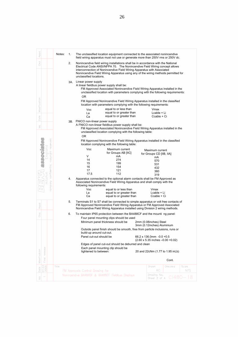
Notes: 1. The unclassified location equipment connected to the associated nonincendivefield wiring apparatus must not use or generate more than 250V rms or 250V dc.
2. Nonincendive field wiring installations shall be in accordance with the NationalElectrical Code ANSI/NFPA 70. The Nonincendive Field Wiring concept allowsinterconnection of Nonincendive Field Wiring Apparatus with AssociatedNonincendive Field Wiring Apparatus using any of the wiring methods permitted forunclassified locations.
3A.
4. Apparatus connected to the optional alarm contacts shall be FM Approved asAssociated Nonincendive Field Wiring Apparatus and shall comply with thefollowing requirements:
Voc equal to or less than VmaxLa equal to or greater than Lcable + LiCa equal to or greater than Ccable + Ci
5. Terminals S1 to S7 shall be connected to simple apparatus or volt free contacts ofFM Approved Nonincendive Field Wiring Apparatus or FM Approved AssociatedNonincendive Field Wiring Apparatus installed using Division 2 wiring methods.
6. To maintain IP65 protection between the BA488CF and the mounti ng panel:Four panel mounting clips should be usedMinimum panel thickness should be 2mm (0.08inches) Steel
3mm (0.12inches) AluminiumOutside panel finish should be smooth, free from particle inclusions, runs orbuild-up around cut-out.Panel cut-out should be 66.2 x 136.0mm -0.0 +0.5
(2.60 x 5.35 inches –0.00 +0.02)Edges of panel cut-out should be deburred and cleanEach panel mounting clip should betightened to between: 20 and 22cNm (1.77 to 1.95 inLb)
Cont.
FNICO non-linear power supplyA FNICO non-linear fieldbus power supply shall be:
FM Approved Associated Nonincendive Field Wiring Apparatus installed in the unclassified location complying with the following table:
OR
FM Approved Nonincendive Field Wiring Apparatus installed in the classified location complying with the following table:
Voc
V 14 15 16 17 17.5 112
121
mA 274199154 432
531570
360319
mA
Maximum current for Groups AB [IIC]
Maximum currentfor Groups CD [IIB, IIA]
FM Approved Nonincendive Field Wiring Apparatus installed in the classified location with parameters complying with the following requirements:
La Ca
Voc
FM Approved Associated Nonincendive Field Wiring Apparatus installed in the A linear fieldbus power supply shall be:Linear power supply
unclassified location with parameters complying with the following requirements:
OR
3B.
equal to or greater than equal to or greater than
equal to or less than Vmax
Ccable + CiLcable + Li
27
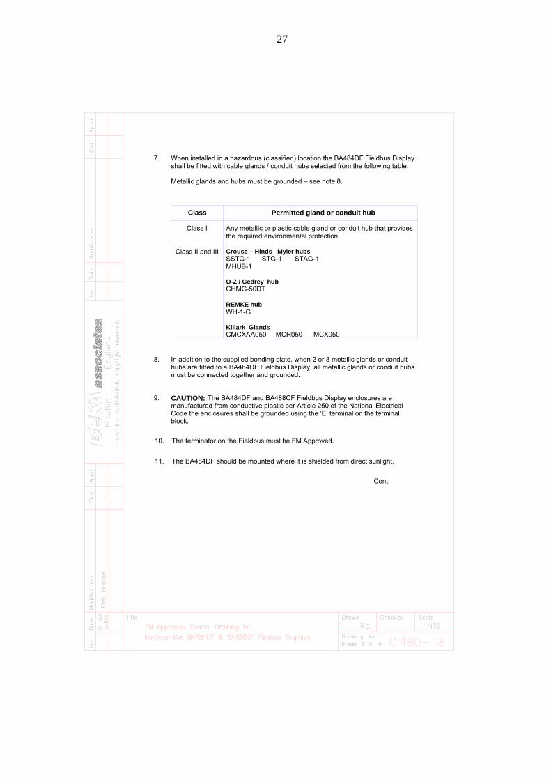
must be connected together and grounded.
Code the enclosures shall be grounded using the ‘E’ terminal on the terminalmanufactured from conductive plastic per Article 250 of the National Electrical
hubs are fitted to a BA484DF Fieldbus Display, all metallic glands or conduit hubsIn addition to the supplied bonding plate, when 2 or 3 metallic glands or conduit
The BA484DF and BA488CF Fieldbus Display enclosures are
block.
CAUTION:9.
8.
Class II and III
Class I
Class
Any metallic or plastic cable gland or conduit hub that providesthe required environmental protection.
SSTG-1 STG-1 STAG-1Crouse – Hinds Myler hubs
CMCXAA050 MCR050 MCX050
Permitted gland or conduit hub
MHUB-1
CHMG-50DT
Killark Glands
REMKE hub
O-Z / Gedrey hub
WH-1-G
Metallic glands and hubs must be grounded – see note 8.
When installed in a hazardous (classified) location the BA484DF Fieldbus Displayshall be fitted with cable glands / conduit hubs selected from the following table.
7.
The terminator on the Fieldbus must be FM Approved.10.
The BA484DF should be mounted where it is shielded from direct sunlight.11.
Cont.

28
FNICO Rules
The FNICO Concept allows the interconnection of intrinsically safe apparatus to associated apparatus not specifically examined in such combination. The criterion for such interconnection is that the voltage (Vmax), the current (Imax) and the power (Pmax) which intrinsically safe apparatus can receive and remain intrinsically safe, considering faults, must be equal or greater than the voltage (Uo, Voc or Vt), the current (Io, Isc or It) and the power (Po) which can be provided by the associated apparatus (supply unit). In addition the maximum unprotected residual capacitance (Ci) and inductance (Li) of each apparatus (other than terminators) connected to the Fieldbus must be less than or equal to 5nF and 20uH respectively.In each I.S. Fieldbus segment only one active source, normally the associated apparatus, is allowed to provide the necessary power for the Fieldbus system. The allowed voltage (Uo, Voc or Vt) of the associated apparatus used to supply the bus cable must be limited to the range 14Vdc to 17.5Vdc. All other equipment connected to the bus cable has to be passive, meaning that the apparatus is not allowed to provide energy to the system, except a leakage current of 50µA for each connected device. Separately powered equipment needs galvanic isolation to ensure the intrinsically safety Fieldbus circuit remains passive.The cable used to interconnect the devices needs to comply with the following parameters:Loop resistance R': 15....150/kmInductance per unit length L':0.4....1mH/km
Capacitance per unit length C': 80....200nF/kmC' = C' line/line+0.5 C' line/screen, if both lines are floatingorC' = C' line/line + C'line/screen, if the screen is connected to one line.Length of spur cable: max. 30mLength of trunk cable: max. 1kmLength of splice: max = 1mTerminatorsAt the end of each trunk cable an FM Approved line terminator with the following parameters is suitable:R= 90...100C = 0....2.2µF
System evaluationThe number of passive devices like transmitters, actuators, connected to a single bus segment is not limited due to nonincendive reasons. Furthermore, if the above rules are respected, the inductance and the capacitance of the cable need not be considered and will not impair the intrinsic safety of the installation.
Notes.1. The intrinsic safety FNICO concept allows the interconnection of FM Approved nonincendive devices with FNICO parameters not specifically examined in combination as a system when:Uo or Voc or Vt Vmax"
29
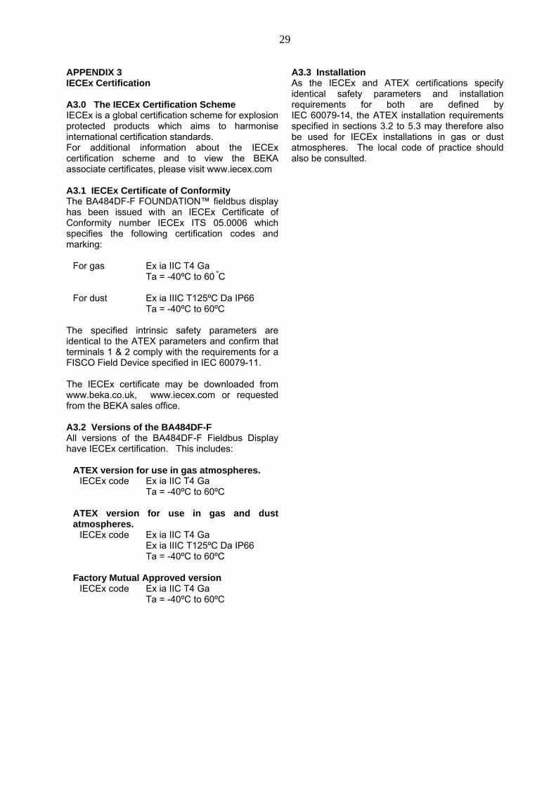
APPENDIX 3IECEx Certification
A3.0 The IECEx Certification SchemeIECEx is a global certification scheme for explosionprotected products which aims to harmoniseinternational certification standards.For additional information about the IECExcertification scheme and to view the BEKAassociate certificates, please visit www.iecex.com
A3.1 IECEx Certificate of ConformityThe BA484DF-F FOUNDATION™ fieldbus displayhas been issued with an IECEx Certificate ofConformity number IECEx ITS 05.0006 whichspecifies the following certification codes andmarking:
For gas Ex ia IIC T4 GaTa = -40ºC to 60 ºC
For dust Ex ia IIIC T125ºC Da IP66Ta = -40ºC to 60ºC
The specified intrinsic safety parameters areidentical to the ATEX parameters and confirm thatterminals 1 & 2 comply with the requirements for aFISCO Field Device specified in IEC 60079-11.
The IECEx certificate may be downloaded fromwww.beka.co.uk, www.iecex.com or requestedfrom the BEKA sales office.
A3.2 Versions of the BA484DF-FAll versions of the BA484DF-F Fieldbus Displayhave IECEx certification. This includes:
ATEX version for use in gas atmospheres.IECEx code Ex ia IIC T4 Ga
Ta = -40ºC to 60ºC
ATEX version for use in gas and dustatmospheres.
IECEx code Ex ia IIC T4 GaEx ia IIIC T125ºC Da IP66Ta = -40ºC to 60ºC
Factory Mutual Approved versionIECEx code Ex ia IIC T4 Ga
Ta = -40ºC to 60ºC
A3.3 InstallationAs the IECEx and ATEX certifications specifyidentical safety parameters and installationrequirements for both are defined byIEC 60079-14, the ATEX installation requirementsspecified in sections 3.2 to 5.3 may therefore alsobe used for IECEx installations in gas or dustatmospheres. The local code of practice shouldalso be consulted.