ba63-01 titelseite fa idnr5985940 m51p minipress user manual.pdf · %$˜0,1,35(66 ˜)$ ˜,g1u ˜s...
TRANSCRIPT

Blum MINIPRESS
The machine shall only beused by trained personnelwho have completely readand understand themanual.
�
�

1
�
THE MACHINE SHALL ONLY BE USED BY TRAINEDPERSONNEL WHO HAVE COMPLETELY READ ANDUNDERSTAND THE MANUAL.
USCONTENTS Page:
A How to use this manual 2
B Safety instructions 3
C Designation of parts 6
D Initial set-up of MINIPRESS
á�Unpacking and assembly 10
á�Connection to compressed air system 13
á�Electrical connection 14
á�Dust extraction 14
E Description of operating panel 15
F Hinge insertion process
á�Drilling of hinge pattern 18
á�Hinge insertion 26
G Installation of wing mounting plates 29
H Drilling of line patterns 32
J Service and maintenance 35
K Troubleshooting - What to do, if...? 38
L Appendix
á�Do-it-yourself worktable 46
á�Warranty 47
á�Technical data 48
á�Warranty cards --
%$������0,1,35(66�)$�,G1U���������S�� ����������������$0�

2
A
How to use the manual
B
(G1)
�
!
How to use this manual
1. Understanding this manual 2. Symbols and their descriptions:
• THE MACHINESHOULD ONLY BEUSED BY TRAINEDPERSONNEL WHOHAVE COMPLETELYREAD AND UNDER-STAND THE MANUAL
• To better identify the machinecomponents, see section C -„Designation of parts“.
• Each section is marked with a capitalletter and a symbol that correspondsto the Table of Contents.
Indicates important safetyrules which must be followed!
Indicates an importantcomment.
Component description codefound throughout the manualand on the fold-out pages.The letter corresponds to thesection where the componentand it’s function is described.
Example:G1 is described in section G.
This capital letter indicatesthe section and is shown onthe outer edge of the section.It is intended to aid insearching through themachine manual.
%$������0,1,35(66�)$�,G1U���������S�� ����������������$0�

3
B
�Safety instructions
������
����������� ���������� ������� ���
�������������������
�
Safety instructions
Read before operation
• Failure to properly follow all safetyrules and procedures in this manual,and all warnings and instructions onthe machine, may result in seriouspersonal injury or property damage.
Safety decal description
• Before connecting your machineto a power source, be sure to readALL Safety Rules and theinstruction manual!
• Wear safety glasses or a full face
shield when operating this machine.
• Keep unauthorized people awayfrom the machine. Only one personat a time must operate the machine.
• Disconnect electrical and pneumaticconnections before making any
repairs or adjustments.
• Electrical connections andmaintenance must be performed bya qualified electrician. An electricaldiagram is included in theinstructions.
%$������0,1,35(66�)$�,G1U���������S�� ����������������$0�

4
B
� Safety instructions
�������
������� ����
������
������� ����
�
• Keep hands and fingers away from drillbits while the machine is powerconnected, even if it is not running.
• Never attempt to operate machinewithout the guards in place.
• Never move your hands in the area ofpinch points.
Safety rules
• This machine is designed forcommercial and industrialapplications and shall be used byfully trained professionals only.The machine is only intended for thedrilling and insertion of Blumhardware into panels of wood,particle board, or laminated particleboard.
• Always place operation mode switchto „set up“ position and disconnectthe power (unplugged) beforeperforming any work on the drillheads, fences or stops.
• Keep work area clean. Clutteredareas and work stations increase thechance of accidents.
• Protect yourself from electricalshock. Do not use this machine indamp or wet locations, or expose itto rain.
• Consider environmental factors andlocal laws when setting-up andoperating the machine.
• The hold-down clamps or otheradequate means must be used tosecure the panel during theoperation.
• Observe the location of the controlswitches and become familiar withtheir operation.
• Wear proper clothing. Do not wearshirts with bulky sleeves and tiesthat could be caught in movingparts.
• Do not wear jewelry when operatingthis machine. Individuals with longhair should wear a hairnet to protecttheir hair from moving parts.
%$������0,1,35(66�)$�,G1U���������S�� ����������������$0�

5
B
�Safety instructions
• Before every use of the machine,make sure that all safety devicesand parts of the machine functionproperly. Any defective safetydevices and accessories must berepaired or exchanged by a qualifiedservice technician only.
• Do not overreach. Keep properfooting and balance at all times.
• CAUTION: For your own safety, useonly those accessories which arerecommended or indicated in themanual or Blum sales literature.
• All accessories and attachmentsmust be installed as described in themanual to assure a proper and safeoperation of the machine.
• Maintain tools with care. Keep toolssharp, clean and organized for thebest and safest performance. Followinstructions for lubricating andchanging accessories.
• Protect electrical and pneumaticlines from heat, oil, traffic, sharpedges, etc.
• Do not use cables and pneumaticlines for purposes other than thoseoriginally intended.
• The actual noise levels in your workarea may vary. Appropriate hearingprotection may be necessary. Thisdetermination must be made by theuser with consideration for the entireworking environment and anyapplicable regulation. Factors liableto influence current immission levelsin the workplace include the lengthof exposure, the characteristics ofthe workroom, and other noisesources.
• This machine, being cord and plugconnected is in compliance withOSHA regulations 1910.147 (lock-out/ tag-out) and does not requirepadlocks or other locking devices.
• For any question or problem with themachine, contact the BlumCustomer Service Department:1-800-438-6788
%$������0,1,35(66�)$�,G1U���������S�� ����������������$0�

6
C
Designation of parts
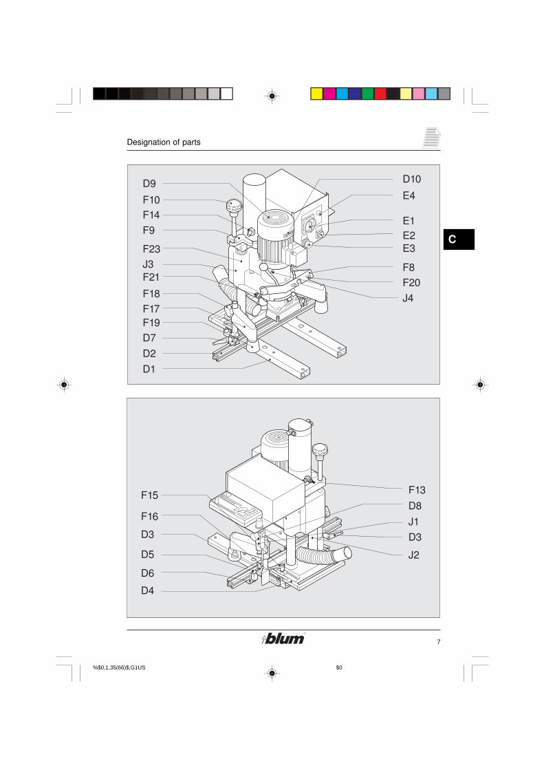
Designation of parts
D1 ...machine baseD2 ...base rulerD3 ... clamping leverD4 ... fencing systemD5 ... fixing pins for rulerD6 ... indexing plateD7 ... swivel stopD8 ...air filterD9 ... fanD10 ... rotation direction arrow
E1 ...main switchE2 ...drill / press stroke buttonE3 ...hold-down switchE4 ...operation Indicator Lamp
F8 ... swing armF9 ...drilling depth gaugeF10 ...adjustment for drilling depthF13 ...adjustment screw for stroke
speedF14 ...adjustment screw for braking
stroke
F15 ...clamping leverF16 ... fixing pinF17 ...hold-down clampF18 ... locking screwF19 ...hold-down guardF20 ... fastening screw for ramF21 ...adjustment screw for swing
armF23 ...drill/press unit
J1 ...air filter - water trapJ2 ...guide shaftsJ3 ... lubricating nipplesJ4 ...motor fastening bolts
%$������0,1,35(66�)$�,G1U���������S�� ����������������$0�
7
C
Designation of parts
�
�
��
��������
����
� ����� ��!
���
"�
"�"#
"�
���
$# �!
��#
$�
���
�#
�%
�!
��
�&
��%
��&
$�
��#
$��#
%$������0,1,35(66�)$�,G1U���������S�� ����������������$0�

8
C
Designation of parts
Designation of parts
D7 ... swivel stopD13 ...box support
F3 ... cover capsF5 ... fixing pin for drill headF6 ... lever (to rotate gearbox)F7 ... symbol furniture hingeF11 ...drilling depth stopF12 ... retaining ring
G3 ... symbol line boring pattern
H3 ... setting gauge
J6 ... clutch
%$������0,1,35(66�)$�,G1U���������S�� ����������������$0�

9
C
Designation of parts
�
���
�&
�%
'#
�
�#���
(
(
)# $&
��#
&�
%$������0,1,35(66�)$�,G1U���������S�� ����������������$0�

10
D
Initial set-up of MINIPRESS
�
)
* �
(
(
(
(
��
Unpacking and assembly
1. MINIPRESS footprint
H = 27-15/16"B = 24"T = 29-15/16"
2. Unpack MINIPRESS and fasten itto a suitable table using bolts.
• Open the box.
• Get an assistant to help you liftMINIPRESS onto the worktable.
Warning:The machine weightsapprox. 82 lbs (37 kg) somake sure that the table issturdy enough!
• Fit M8 bolts through the drill holes(D1) and tighten them.
• Do not install MINIPRESS in a damparea but in a dry room.
%$������0,1,35(66�)$�,G1U���������S�� ����������������$0��

11
D
Initial set-up of MINIPRESS
!
�%
�&
�#
��
#+!,
-�����.
(
(
�/
�/
#/
�
3. Installation of base ruler (D2)
• Loosen both clamping levers (D3)on the fencing System.
• Lift locating pin (D5), and slide baseruler (D2), until the locating pinsnaps into the center hole of thelocating plate (D6).
• Tighten clamping levers (D3).
4. Mounting the swivel stops (D7)
• Loosen the locking bolt until the T-nut projects by 3/8“ (10 mm).
• Tilt the swivel stop against the rulerand raise the stop.
• Tighten the locking bolt.
Note:
Follow the same procedure toplace a stop between twoexisting stops.
%$������0,1,35(66�)$�,G1U���������S�� ����������������$0��
12
D
Initial set-up of MINIPRESS
��
0
��#
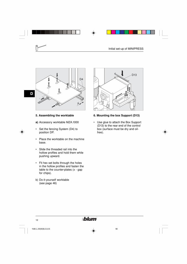
5. Assembling the worktable
a) Accessory worktable MZA.1000
• Set the fencing System (D4) toposition DP.
• Place the worktable on the machinebase.
• Slide the threaded rail into thehollow profiles and hold them whilepushing upward.
• Fit hex set bolts through the holesin the hollow profiles and fasten thetable to the counter-plates (x - gapfor chips).
b) Do-it-yourself worktable(see page 46)
6. Mounting the box Support (D13)
• Use glue to attach the Box Support(D13) to the rear end of the controlbox (surface must be dry and oil-free).
%$������0,1,35(66�)$�,G1U���������S�� ����������������$0��
13
D
Initial set-up of MINIPRESS
�
!
�!
Connection to compressed air system
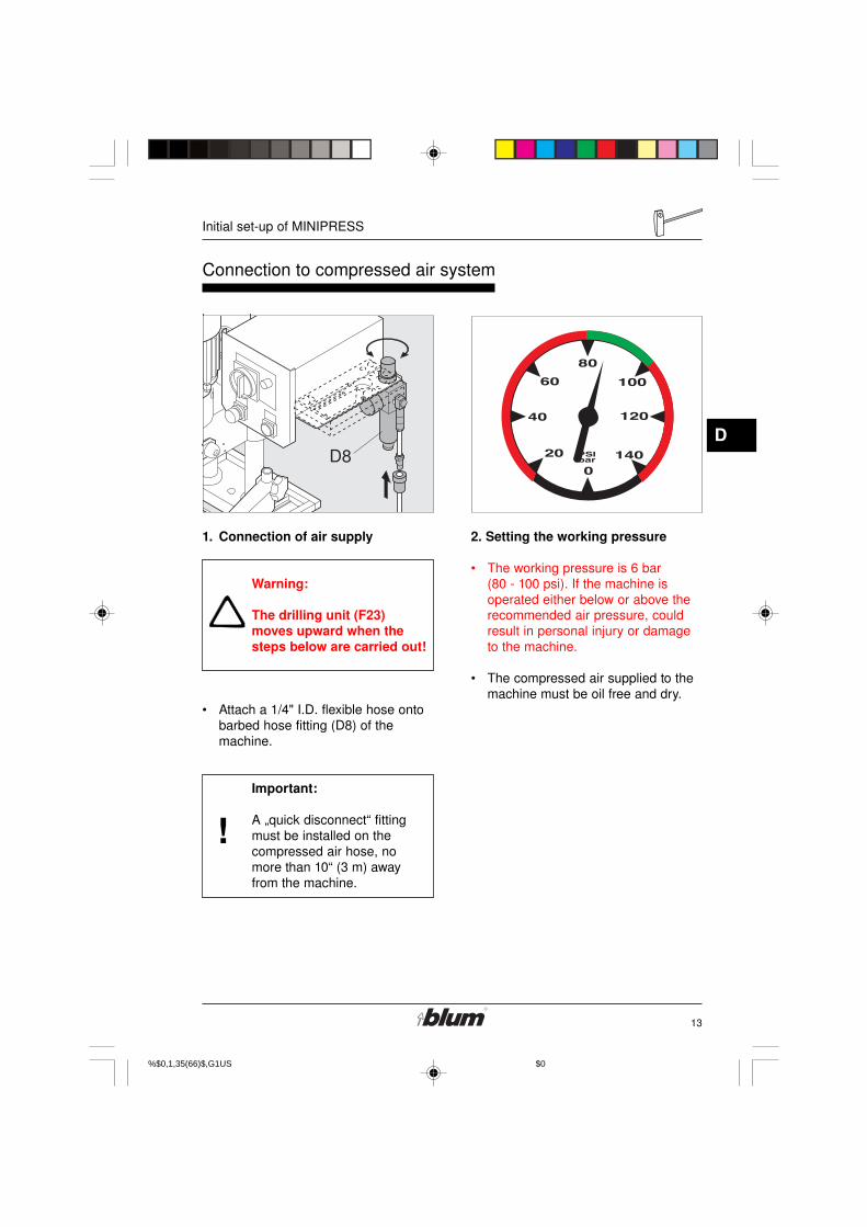
1. Connection of air supply
Warning:
The drilling unit (F23)moves upward when thesteps below are carried out!
• Attach a 1/4" I.D. flexible hose ontobarbed hose fitting (D8) of themachine.
Important:
A „quick disconnect“ fittingmust be installed on thecompressed air hose, nomore than 10“ (3 m) awayfrom the machine.
2. Setting the working pressure
• The working pressure is 6 bar(80 - 100 psi). If the machine isoperated either below or above therecommended air pressure, couldresult in personal injury or damageto the machine.
• The compressed air supplied to themachine must be oil free and dry.
%$������0,1,35(66�)$�,G1U���������S�� ����������������$0��
14
D
Initial set-up of MINIPRESS
�
!
000�1�+�00�)2
�3��������������� �3������3
�3��������������
�3������3���� �������������������4��4�����44����
�3����� �������������������4��4�����44����
�3�����
�3����� �������������������4��4�����44�����3����
�3����� �������������������4��4�����44����
�3����� �������������������4��4�����44����
�3�3
�3
�3
�3�3�3�3
�3
�3
�3�3
�3�3�3
�3
�3
�3
�3
�3
�3�3�3
�3�3�3�3
�3
�3
�3
�3�3
�3�3�3�3
�/
�/
#/
Electrical connection Dust extraction
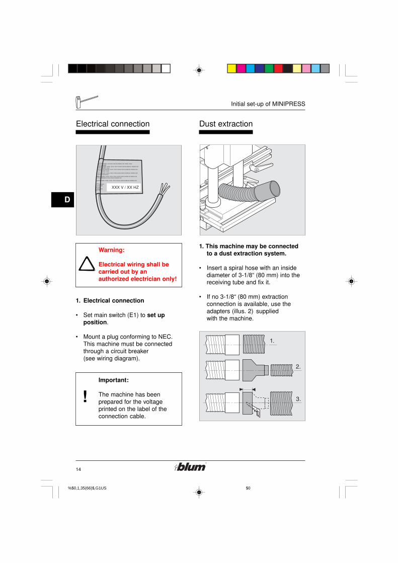
Warning:
Electrical wiring shall becarried out by anauthorized electrician only!
1. Electrical connection
• Set main switch (E1) to set upposition.
• Mount a plug conforming to NEC.This machine must be connectedthrough a circuit breaker(see wiring diagram).
Important:
The machine has beenprepared for the voltageprinted on the label of theconnection cable.
1. This machine may be connectedto a dust extraction system.
• Insert a spiral hose with an insidediameter of 3-1/8“ (80 mm) into thereceiving tube and fix it.
• If no 3-1/8“ (80 mm) extractionconnection is available, use theadapters (illus. 2) suppliedwith the machine.
%$������0,1,35(66�)$�,G1U���������S�� ����������������$0��

15
E
Desciption of operating panel
�
"�
"#
"�
"�
�����
�����+�����
5�� ��� �����+��������4�
"� �����
�����+�����
5�� ��� �����+��������4�
Description of operating panel
2. Designation of operatingelements
• (E1) ... main switch
• (E2) ... press drill / press stroke button
• (E3) ... hold-down switch
• (E4) ... operation indicator lamp
3. Main switch (E1)
Warning:
The main switch does notdisengage the machinefrom the compressed-airsystem.
Set up position:Operation indicator lamp (E4)does not light up. machine isin set-up mode.- Motor cannot start.- stroke can be performed.
drill / press position:Operation indicator lamp(E4) lights up. machine isin operating mode.- Drilling and insertion of fittings is possible.
%$������0,1,35(66�)$�,G1U���������S�� ����������������$0��
16
E
Description of operating panel
��
!
�����+��������4�
�����+��������4�
�����+��������4�
+
+
+
�
�
���
�� "�
"�
5
"�
�����
�����+�����
5�� ��� �����+��������4�
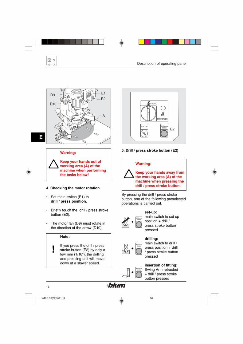
Warning:
Keep your hands out ofworking area (A) of themachine when performingthe tasks below!
4. Checking the motor rotation
• Set main switch (E1) todrill / press position.
• Briefly touch the drill / press strokebutton (E2).
• The motor fan (D9) must rotate inthe direction of the arrow (D10).
Note:
If you press the drill / pressstroke button (E2) by only afew mm (1/16"), the drillingand pressing unit will movedown at a slower speed.
5. Drill / press stroke button (E2)
Warning:
Keep your hands away fromthe working area (A) of themachine when pressing thedrill / press stroke button.
By pressing the drill / press strokebutton, one of the following preselectedoperations is carried out.
set-up:main switch to set upposition + drill /press stroke buttonpressed
drilling:main switch to drill /press position + drill/ press stroke buttonpressed
insertion of fitting:Swing Arm retracted+ drill / press strokebutton pressed
%$������0,1,35(66�)$�,G1U���������S�� ����������������$0��

17
E
Desciption of operating panel
5�� ���
5�� ���
"#
�����
�����+�����
5�� ��� �����+��������4�
"�
5. Hold-down switch (E3)
Pos. Hold-down clamps onPressing the drill / pressstroke button (E2) causes thehold-down clamps to extendautomatically.
Pos. Hold-down clamps offThe clamps remain retractedif you press the drill / pressstroke button (E2).
%$������0,1,35(66�)$�,G1U���������S�� ����������������$0��

18
F
Drilling of hinge pattern
!
���� �� �#
��
�6�+�,
-% ���.
Drilling of hinge pattern
1. Necessary parts
• drill bits:- one 35 mm dia. rotating clockwise(F1) (marked black).- two 8 mm dia. rotating counter-clockwise (F2) (marked orange).
• Two cover caps (F3)
• Insertion ram MZM.XXXX (F4).See Blum catalog for correct ram.
• Door panel
• Hinge
2. drill-bit length
• The max length of the drill bits (frombit-tip to adjustment screw) shall be2 -1/4“ (57 mm).
• To correct drill-bit length, adjustscrew accordingly.
Important:
All drill bits shall be the samelength!
%$������0,1,35(66�)$�,G1U���������S�� ����������������$0��

19
F
Drilling of hinge pattern
#%
�#
!��
�� ��
���� ��
�#
!
�%
�
�&
3. Select drill pattern
• Pull out fixing pin (F5) on drillhead.
• At the same time, move lever (F6)to symbol for hinge drilling pattern(F7).
• Make sure fixing pin (F5) snapsback to lock gearbox position!
4. Install drill bits
• Before installing drill bits, alwaysdisconnect the machine from it’selectrical source (unplugged).
• main switch (E1) to set up position.
• Push drill bits all the way in to thechucks. Tighten set screw on flatspot of drill-bit shank only.
• Use a hex wrench to tighten thefastening screws. (4 mm)
• Insert cover cap (F3) into the emptychucks. This keeps set screws inplace, and prevents wood chips fromaccumulating in chucks.
%$������0,1,35(66�)$�,G1U���������S�� ����������������$0��
20
F
Drilling of hinge pattern
!
5�� ���
���
��
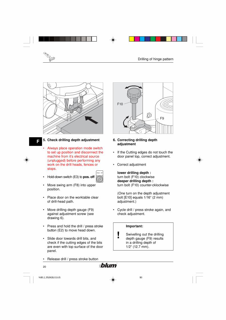
5. Check drilling depth adjustment
• Always place operation mode switchto set up position and disconnect themachine from it’s electrical source(unplugged) before performing anywork on the drill heads, fences orstops.
• Hold-down switch (E3) to pos. off
• Move swing arm (F8) into upperposition.
• Place door on the worktable clearof drill-head path.
• Move drilling depth gauge (F9)against adjustment screw (seedrawing 6).
• Press and hold the drill / press strokebutton (E2) to move head down.
• Slide door towards drill bits, andcheck if the cutting edges of the bitsare even with top surface of the doorpanel.
• Release drill / press stroke button
6. Correcting drilling depthadjustment
• If the Cutting edges do not touch thedoor panel top, correct adjustment.
• Correct adjustment
lower drilling depth :turn bolt (F10) clockwisedeeper drilling depth :turn bolt (F10) counter-cklockwise
(One turn on the depth adjustmentbolt [E10] equals 1/16“ (2 mm)adjustment.)
• Cycle drill / press stroke again, andcheck adjustment.
Important:
Swivelling out the drillingdepth gauge (F9) resultsin a drilling depth of1/2“ (12.7 mm).
%$������0,1,35(66�)$�,G1U���������S�� ����������������$0��
21
F
Drilling of hinge pattern
!
������
��#
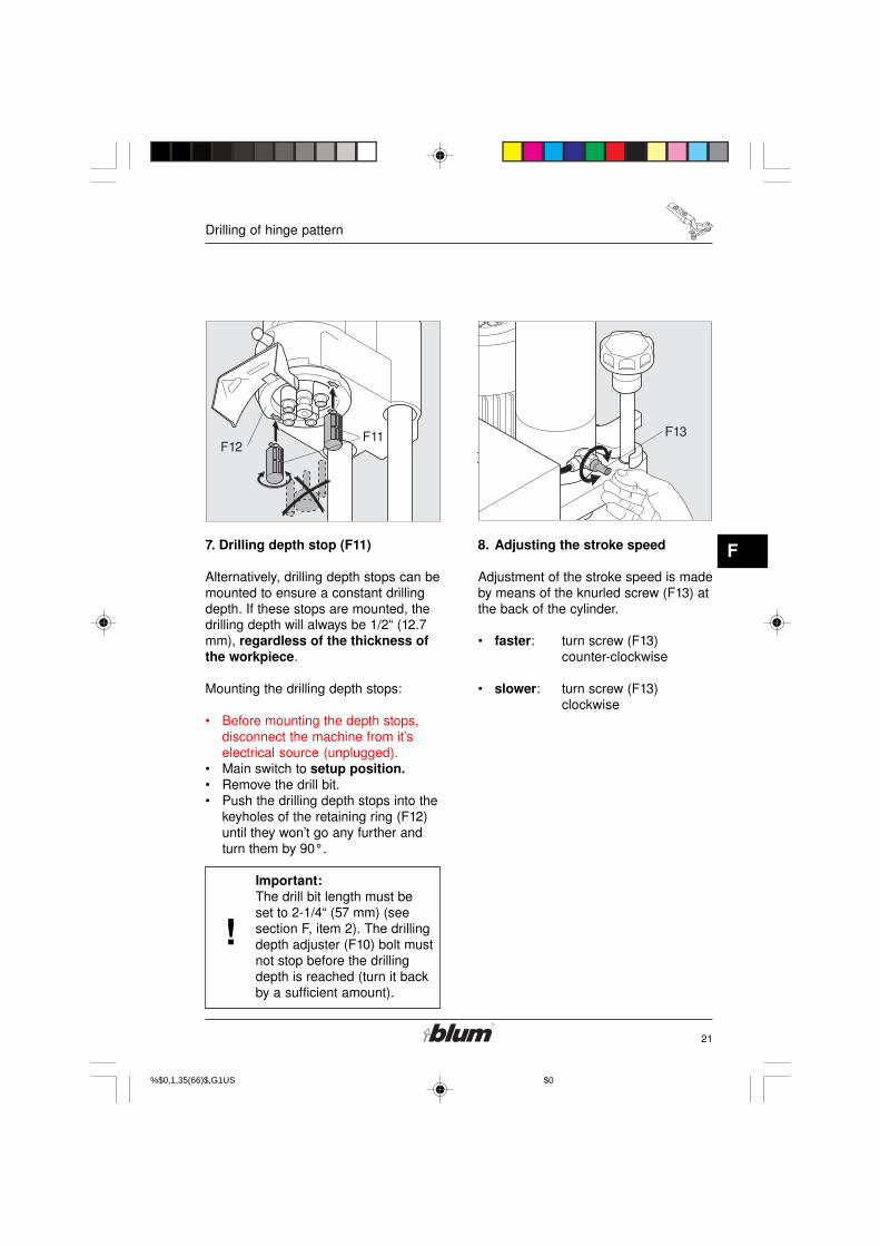
7. Drilling depth stop (F11)
Alternatively, drilling depth stops can bemounted to ensure a constant drillingdepth. If these stops are mounted, thedrilling depth will always be 1/2“ (12.7mm), regardless of the thickness ofthe workpiece.
Mounting the drilling depth stops:
• Before mounting the depth stops,disconnect the machine from it’selectrical source (unplugged).
• Main switch to setup position.• Remove the drill bit.• Push the drilling depth stops into the
keyholes of the retaining ring (F12)until they won’t go any further andturn them by 90°.
Important:The drill bit length must beset to 2-1/4“ (57 mm) (seesection F, item 2). The drillingdepth adjuster (F10) bolt mustnot stop before the drillingdepth is reached (turn it backby a sufficient amount).
8. Adjusting the stroke speed
Adjustment of the stroke speed is madeby means of the knurled screw (F13) atthe back of the cylinder.
• faster: turn screw (F13)counter-clockwise
• slower: turn screw (F13)clockwise
%$������0,1,35(66�)$�,G1U���������S�� ����������������$0��
22
F
Drilling of hinge pattern
�
�
��"�
"�
5���
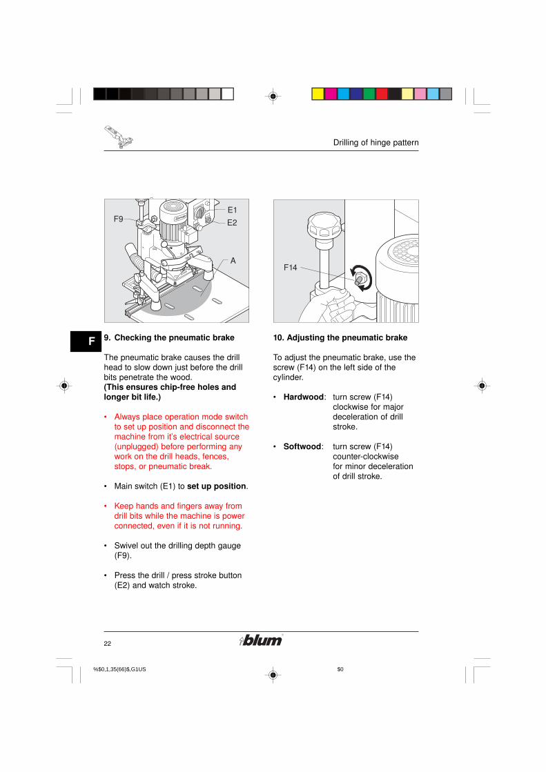
9. Checking the pneumatic brake
The pneumatic brake causes the drillhead to slow down just before the drillbits penetrate the wood.(This ensures chip-free holes andlonger bit life.)
• Always place operation mode switchto set up position and disconnect themachine from it’s electrical source(unplugged) before performing anywork on the drill heads, fences,stops, or pneumatic break.
• Main switch (E1) to set up position.
• Keep hands and fingers away fromdrill bits while the machine is powerconnected, even if it is not running.
• Swivel out the drilling depth gauge(F9).
• Press the drill / press stroke button(E2) and watch stroke.
10. Adjusting the pneumatic brake
To adjust the pneumatic brake, use thescrew (F14) on the left side of thecylinder.
• Hardwood: turn screw (F14)clockwise for majordeceleration of drillstroke.
• Softwood: turn screw (F14)counter-clockwisefor minor decelerationof drill stroke.
%$������0,1,35(66�)$�,G1U���������S�� ����������������$0��

23
F
Drilling of hinge pattern
!
��%
��&
78 9* �: 78 9* �:
�
��
��
#�
��
%�
78
9*
�:
��&
:��/��+�
:��/�#+�
:��/��%
11. Fencing System (D4) adjustments
• Always place operation mode switchto set up position and disconnect themachine from it’s electrical source(unplugged) before performing anywork on the drill heads, fences,stops, or pneumatic break.
• Release both clamping levers (F15).
• Pull out the fixing pins (F16) on bothsides and set the stop system (D4)to MB.
Note:
The fencing system includes5 fixing positions.(see point 12 )
• Tighten the clamping levers (F15) onboth sides.
12. Fixed positions of the stop system
• Always place operation mode switchto set up position and disconnect themachine from it’s electrical source(unplugged) before performing anywork on the drill heads, fences,stops, or pneumatic break.
Pos. 1 = 5 mm (3/16“)Lock the fixing bolts (F16) into placeand pull the stop system forward.
Pos. 2 = 9 mm (3/8“)Lock the fixing bolts (F16) into placeand push the stop system backward.
Pos. 3 = 20 mm (13/16“)Lock the fixing bolts (F16) into placeand pull the stop system forward.Setting: ‘DP’
Pos. 4 = 23.5 mm (15/16“)Lock the fixing bolts (F16) into placeand push the stop system backward.Setting: ‘MB’
Pos. 5 = 37 mm (1-7/16“)Lock the fixing bolts (F16) into place.Setting: ‘SY’
%$������0,1,35(66�)$�,G1U���������S�� ����������������$0��

24
F
Drilling of hinge pattern
!
!
(
� ���
13. Setting the swivel stops (D7)
• Always place operation modeswitch to set up position anddisconnect the machine from it’selectrical source (unplugged) beforeperforming any work on the drillheads, fences, stops, or pneumaticbreak.
Set the swivel stops (D7) to therequired dimension and secure them.
Note:
The reading edge is on theinside of the swivel part!
14. Place the door on the worktableand slide it until positionedat the stop.
Note:
For work pieces with groovesor radii (see illus.), the stop facecan be increased by pulling thestop lock forward.
%$������0,1,35(66�)$�,G1U���������S�� ����������������$0��

25
F
Drilling of hinge pattern
0
��!
��
���
15. Adjust hold down clamps (F17)
• Loosen clamp screw (F18).
• Position clamp over panel surface.
• Position clamp over panel surface,no more than 6 mm (1/4").
• Tighten clamp screws (F18).
%$������0,1,35(66�)$�,G1U���������S�� ����������������$0��

26
F
Hinge insertion
���
�!
16. Mount insertion ram onto swingarm (F8) in upright position
• Place ram over fixing bolts (F20)on swing arm (F8) and tighten.
• Make sure that ram adjustmentscrews sit on fixing bolt.
Hinge insertion
17. Attaching the hinge on to theram.
%$������0,1,35(66�)$�,G1U���������S�� ����������������$0��

27
F
Hinge insertion
�
5�� ���
!
�
�
"�
"�
"#
��
�
5
�!
���
�!
���
18. Drilling
WARNING!To avoid serious injury, allitems must be removedfrom the working area of themachine, except theworkpiece! Keep your handsout of working area (A).
• Swivel out the drilling depth gauge (F9).
• Set the main switch (E1) to drill /press position.
• Set the hold-down switch (E3)to pos. off
• Be sure to swivel the swing arm (F8)upward.
• When drilling, keep one hand againstthe outside edge of the door nearestto you (outside of zone A) and push itagainst the swivel stops - D7.
• Press the drill / press stoke button(E2) until the drilling depth is reached.
• Release the drill / press stroke button
19. Check alignment of swing arm(F8)
• Move Swing Arm (F8) down to stop
• Make sure the hinge is aligned withthe drilled hole.
• There are two possibilities whichcould cause misalignment:
a) Swing arm (F8) is not vertical:adjust screw (F21).
b) Insertionram is off center:adjust ram adjustment screws(F22).
Note:
If you press the drill / pressstroke button (E2) by only afew mm (1/16"), the drillingand pressing unit will movedown at a slower speed.
%$������0,1,35(66�)$�,G1U���������S�� ����������������$0��

28
F
Hinge insertion
�
�
�
"�
"�
"#
��
�
5
�!
19. Hinge insertion
WARNING!
To avoid serious injury stayclear of drilling area and allpinch points (zone A)except the workpiece.
• When inserting hinge, keep onehand on the drill / press strokebutton (E2) and the other hand onthe swing arm (F8) or on the edgeof the door nearest you until thehinge is totally pressed in (outsideof zone A).
• Release drill / press stroke button.
• Move swing arm (F8) up.
• Release the hold-down clamps bybriefly touching the hold-downswitch (E3).
%$������0,1,35(66�)$�,G1U���������S�� ����������������$0��
29
G
Installation of wing mounting plates
'�'� �#
'�
%
�#
'#
�&
'�
�#
�#
'� '�
%
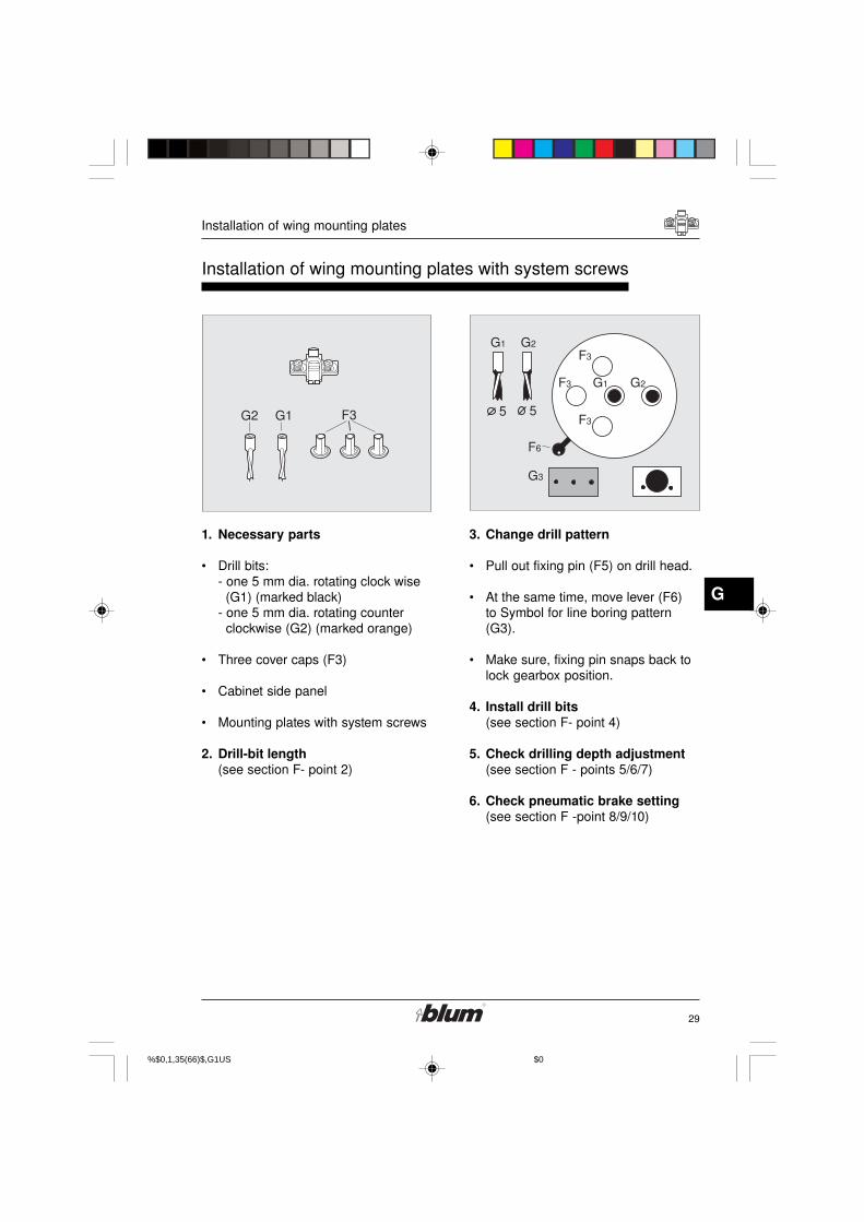
Installation of wing mounting plates with system screws
1. Necessary parts
• Drill bits:- one 5 mm dia. rotating clock wise (G1) (marked black)- one 5 mm dia. rotating counter clockwise (G2) (marked orange)
• Three cover caps (F3)
• Cabinet side panel
• Mounting plates with system screws
2. Drill-bit length(see section F- point 2)
3. Change drill pattern
• Pull out fixing pin (F5) on drill head.
• At the same time, move lever (F6)to Symbol for line boring pattern(G3).
• Make sure, fixing pin snaps back tolock gearbox position.
4. Install drill bits(see section F- point 4)
5. Check drilling depth adjustment(see section F - points 5/6/7)
6. Check pneumatic brake setting(see section F -point 8/9/10)
%$������0,1,35(66�)$�,G1U���������S�� ����������������$0��

30
G
Installation of wing mounting plates
!
��%
��&
78
�&
�%
�&
(
�&
�&
�%
�&�&
(
�&��
7. Setting the fencing system (D4)
• Always place operation mode switchto set up position and disconnect themachine from it’s electrical source(unplugged) before performing anywork on the drill heads, fences,stops, or pneumatic break.
• Release both clamping levers (F15).
• Pull out both fixing pins (F16) andset the stop system (D4) to SY.
• Firmly tighten both clamping levers(F15).
This fixed setting provides for adrilling distance of 1-7/16“ (37 mm).
8. Setting the swivel stops (D7)
• Always place operation mode switchto set up position and disconnect themachine from it’s electrical source(unplugged) before performing anywork on the drill heads, fences,stops, or pneumatic break.
a) If the lower edge of the door is to beflush with the lower edge of thecabinet, only the base ruler (D2)needs to be repositioned.
Repositioning the base ruler:
• Release the two clamping levers(D3) which hold the ruler in place.
• Lift up the fixing pin (D5) and movethe ruler (D2) in the direction of theouter drill bit until the fixing pin (D5)locks into the outer drill hole of theindexing plate (D6).
• Firmly tighten clamping levers (D3).
Note:This step compensates forthe 0-point offset of the wingmounting plate (see illus. 8).
%$������0,1,35(66�)$�,G1U���������S�� ����������������$0��

31
G
Installation of wing mounting plates
!
�&
�#
�%
�&�&
(
0
�#
�%
0
�
�
"�
"�
"#
��
�!
�
5
b) If the lower edge of the door is to belonger or shorter than the loweredge of the cabinet, the stops (D7)must be adjusted accordingly by thedifference in dimension. In addition,the base ruler (D2) must berepositioned.
Positioning the stops and ruler:
• Relocate the stops by dimension (x).
• Release the two clamping levers(D3) which hold the ruler in place.
• Lift up the fixing pin (D5) and movethe ruler (D2) in the direction of theouter drill bit until the fixing pin (D5)locks into the outer drill hole of theindexing plate (D6).
Note:
This step compensates forthe 0-point offset of the wingmounting plate (see illus 8).
9. Place the cabinet side on theworktable and slide it to the stop(see section F - point 14)
10. Set the hold down clamp overpanel surface, no more than6 mm (1/4"),(see section F - point 15).
11. Drilling(see section F - point 18)
12. Releasing the hold-down clamps
• Briefly touch the hold-down switch(E3).
• Slide the cabinet side to the nextstop.
%$������0,1,35(66�)$�,G1U���������S�� ����������������$0��
32
H
Drilling of line patterns
)�)� �#)�
)#�#
'#
)� )�)�
�#
)�)� )�
�&
% % %
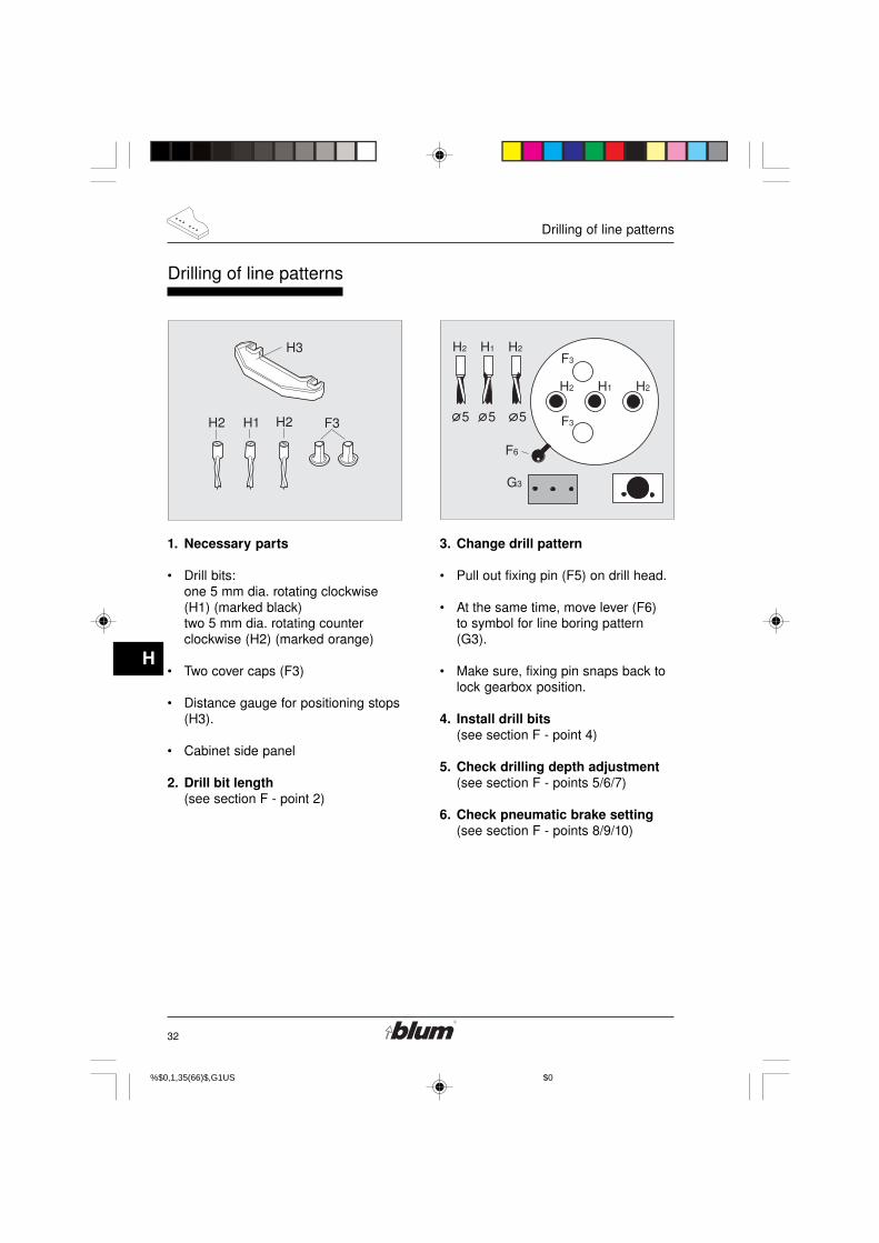
Drilling of line patterns
1. Necessary parts
• Drill bits:one 5 mm dia. rotating clockwise(H1) (marked black)two 5 mm dia. rotating counterclockwise (H2) (marked orange)
• Two cover caps (F3)
• Distance gauge for positioning stops(H3).
• Cabinet side panel
2. Drill bit length(see section F - point 2)
3. Change drill pattern
• Pull out fixing pin (F5) on drill head.
• At the same time, move lever (F6)to symbol for line boring pattern(G3).
• Make sure, fixing pin snaps back tolock gearbox position.
4. Install drill bits(see section F - point 4)
5. Check drilling depth adjustment(see section F - points 5/6/7)
6. Check pneumatic brake setting(see section F - points 8/9/10)
%$������0,1,35(66�)$�,G1U���������S�� ����������������$0��

33
H
Drilling of line patterns
��%
��&
78
(
(
�
)#
7. Adjust fencing system (D4)
• Always place operation modeswitch to set up position anddisconnect the machine from it’selectrical source (unplugged) beforeperforming any work on the drillheads, fences, stops, or pneumaticbrake.
• Release clamping levers (F15).
• Pull out locating pin (F16), andadjust fencing system (D4) to pos.SY.
• Tighten clamping levers (F15).
With this adjustment, the distancebetween fence and the centerline ofthe drill bits is 37 mm.
8. Adjust positioning stops (D7)(see section F - point 13)
9. Line boring
• Use Distance Gauge (H3) to setadditional positioning stops.
This will set a 3-3/4“ (96 mm) distancebetween the stops and provide aconsecutive 1-1/4“ (32 mm) line boringpattern.
%$������0,1,35(66�)$�,G1U���������S�� ����������������$0��

34
H
Drilling of line patterns
�
�
"�
"�
"#
��
� 5
�!
10. Slide cabinet side panel againstthe fence until positioned at thestop(see section F- point 14)
11. Adjust hold down clamps (F17)(see section F - point 15)
12. Drilling(see section F - point 18)
13. Releasing hold down clamps
• Briefly touch the down-hold switch(E3).
• Position cabinet side panel to thenext stop.
%$������0,1,35(66�)$�,G1U���������S�� ����������������$0��
35
J
Service and maintenance
$�
$�
$#
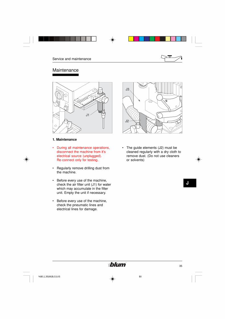
Maintenance
1. Maintenance
• During all maintenance operations,disconnect the machine from it’selectrical source (unplugged).Re-connect only for testing.
• Regularly remove drilling dust fromthe machine.
• Before every use of the machine,check the air filter unit (J1) for waterwhich may accumulate in the filterunit. Empty the unit if necessary.
• Before every use of the machine,check the pneumatic lines andelectrical lines for damage.
• The guide elements (J2) must becleaned regularly with a dry cloth toremove dust. (Do not use cleanersor solvents)
%$������0,1,35(66�)$�,G1U���������S�� ����������������$0��

36
J
Service and maintenance
�
�
$�
$%
$&
2. Replacing a damaged clutch
The clutch is defective if:
• The drill bits get jammed in theworkpiece while the motor fan (D9)keeps on rotating.
Warning !
Replace defective ordamaged partsimmediately! Use onlyoriginal BLUM parts forreplacement!
• Set main switch to set up position.
• When replacing a damaged clutch,machine must be disconnected fromit’s electrical power source and fromit’s compressed air supply andpressure released from machine(use filter bowl drain).
• Remove drill bit.
• Release the four lateral fasteningbolts (J4) from the motor (requiresabout 4 complete turns).
• Lift the motor and rest it on thecontrol system.
Warning:
Secure the motor againstdropping!
• Remove the damping ring (J5).
• Remove the old clutch (J6).
• Mount the new clutch (J6) on theshaft (ensure correct positionbetween clutch and shaft).
• Insert the damping ring (J5).
• Position the bottom part of the clutchready to receive the motor.
• Place the motor on the bottom partof the clutch and make sure that itrests properly on the flange.
• Tighten the four lateral fasteningbolts (J4).
%$������0,1,35(66�)$�,G1U���������S�� ����������������$0��

37
J
Service and maintenance
$
$!
3. Replacing the operation indicatorlamp
• Disconnect the machine from theelectrical supply.
• Set the main switch to set upposition.
• Remove the lamp cover (J7) byreleasing the screw.
• Remove the defective lamp (J8).(Push and turn counter-clockwise).
• Install a new lamp (J8). (Push andturn clockwise).
• Reattach the cover (J7) of theoperation indicator lamp.
%$������0,1,35(66�)$�,G1U���������S�� ����������������$0��

38
K
Troubleshooting - What to do, if ...?
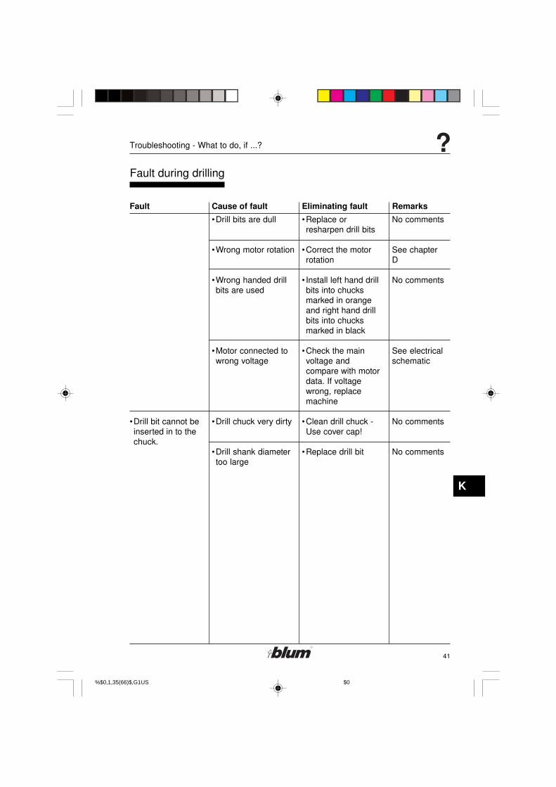
Fault during drilling
•Drilling depth is notreached
•Setting of depthadjustment bolt iswrong
•Drilling depth gaugeswung in
•Drill shorter than 2-1/4“ (57 mm)
•Drill bits notcompletely pushedinto the chucks
•Panel thickness isdifferent thanassumed thickness(e. g. 9/16“ (15 mm)instead of 5/8“
(16 mm))
•Machine hits anobject during downstroke
•Drill / press strokebutton was releasedbefore drilling depthwas reached
•Worktable lower than15/16“ (24 mm)
•Check setting of thedepth adjustmentbolt
•Swing out drillingdepth gauge
•Adjust drill bit
•Clean chucks andpush drill bitcompletely into thechuck
•Check panelthickness
•Adjust drilling depthif necessary
•Use drilling depthstop
•Remove object
•Press the drill strokebutton until thedrilling depth isreached
•Build up theworktable to
15/16“ (24 mm) height
See chapter FF-10
See chapter FF-9
See chapter F
See chapter F
No comments
See chapter F
See chapter F
No comments
No comments
No comments
Fault Cause of fault Eliminating fault Remarks
%$������0,1,35(66�)$�,G1U���������S�� ����������������$0��

39
K
Troubleshooting - What to do, if ...?
Fault during drilling
Fault Cause of fault Eliminating fault Remarks
•Drilled holes areoff-center or holeposition is incorrect
•Pneumatic brake isset too tight
•The fence stops areset wrong
•Ruler incorrectly set
•Wood chips arebetween the fenceand the fencesupports
•Fencing Systemincorrectly set
•The fence extensionis not installedproperly
•Gear box does notengage
•Location pin does notengage into thelocating plate
•Slightly open thethrottle valve
•Check position offence stops andadjust if necessary
•Adjust ruler
•Remove wood chipsand dirt from fencesupport
•Check setting and ifnecessary rectify
•Check fenceextension and fenceextension supports
•Check the distancebetween the rulers
•Allow fixing pin fordrill head to engage
•Check position ofthe location pin
See chapter F
No comments
No comments
No comments
See chapter F
No comments
No comments
See chapter F
See chapterD and G
%$������0,1,35(66�)$�,G1U���������S�� ����������������$0��
40
K
Troubleshooting - What to do, if ...?
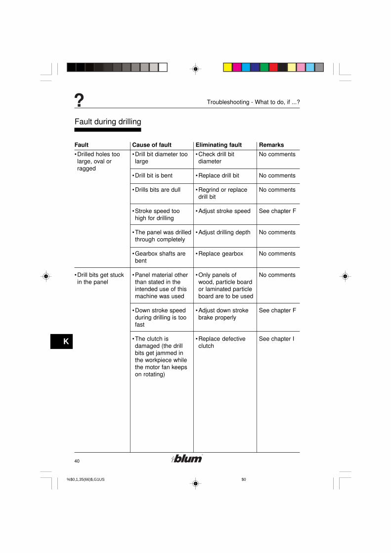
Fault during drilling
Fault Cause of fault Eliminating fault Remarks
•Drilled holes toolarge, oval orragged
•Drill bits get stuckin the panel
•Drill bit diameter toolarge
•Drill bit is bent
•Drills bits are dull
•Stroke speed toohigh for drilling
•The panel was drilledthrough completely
•Gearbox shafts arebent
•Panel material otherthan stated in theintended use of thismachine was used
•Down stroke speedduring drilling is toofast
•The clutch isdamaged (the drillbits get jammed inthe workpiece whilethe motor fan keepson rotating)
•Check drill bitdiameter
•Replace drill bit
•Regrind or replacedrill bit
•Adjust stroke speed
•Adjust drilling depth
•Replace gearbox
•Only panels ofwood, particle boardor laminated particleboard are to be used
•Adjust down strokebrake properly
•Replace defectiveclutch
No comments
No comments
No comments
See chapter F
No comments
No comments
No comments
See chapter F
See chapter I
%$������0,1,35(66�)$�,G1U���������S�� ����������������$0��
41
K
Troubleshooting - What to do, if ...?
Fault during drilling
Fault Cause of fault Eliminating fault Remarks
•Drill bit cannot beinserted in to thechuck.
•Drill bits are dull
•Wrong motor rotation
•Wrong handed drillbits are used
•Motor connected towrong voltage
•Drill chuck very dirty
•Drill shank diametertoo large
•Replace orresharpen drill bits
•Correct the motorrotation
• Install left hand drillbits into chucksmarked in orangeand right hand drillbits into chucksmarked in black
•Check the mainvoltage andcompare with motordata. If voltagewrong, replacemachine
•Clean drill chuck -Use cover cap!
•Replace drill bit
No comments
See chapterD
No comments
See electricalschematic
No comments
No comments
%$������0,1,35(66�)$�,G1U���������S�� ����������������$0��

42
K
Troubleshooting - What to do, if ...?
No comments
No comments
Use counter-sink bit
No comments
No comments
See section F
See section F
No comments
See section F
Fault during Hinge insertion
Fault Cause of fault Eliminating fault Remarks
•Hinges or fittingscannot be insertedat all, or can onlybe inserted withdifficulties
•Air pressure is notsufficient
•The insertion ram orthe swing arm ishitting an object
•The surface of thepanel is too hard
•The drilling depth isnot deep enough
•The diameter of thedrill bits is too small
•The insertion ram isoff-set or installedwrong
•The panel moved onthe work table beforethe insertion cycle
•Shavings in holes
• Insertion ram orswing arm isdisplaced or twisted
•Adjust air pressureto 6 bar (80-100 psi)
•Remove object frompath of insertion ramor swing arm
•Check drillingdistance
•Countersink holes
•See point: Wrongdrilling depth
•Check drill bits andreplace if necessary
•Adjust insertion ram
•Adjust hold-downclamps so paneldoes not moveduring the operation
•Check the shavingsair jet
•drill deeper,if possible
•Adjust insertion ramor swing arm
%$������0,1,35(66�)$�,G1U���������S�� ����������������$0��
43
K
Troubleshooting - What to do, if ...?
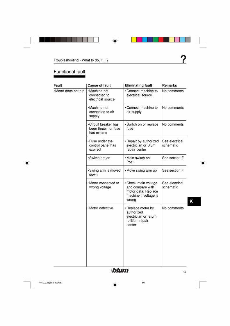
Functional fault
Fault Cause of fault Eliminating fault Remarks
•Motor does not run •Machine notconnected toelectrical source
•Machine notconnected to airsupply
•Circuit breaker hasbeen thrown or fusehas expired
•Fuse under thecontrol panel hasexpired
•Switch not on
•Swing arm is moveddown
•Motor connected towrong voltage
•Motor defective
•Connect machine toelectrical source
•Connect machine toair supply
•Switch on or replacefuse
•Repair by authorizedelectrician or Blumrepair center
•Main switch onPos.1
•Move swing arm up
•Check main voltageand compare withmotor data. Replacemachine if voltage iswrong
•Replace motor byauthorizedelectrician or returnto Blum repaircenter
No comments
No comments
No comments
See electricalschematic
See section E
See section F
See electricalschematic
No comments
%$������0,1,35(66�)$�,G1U���������S�� ����������������$0��

44
K
Troubleshooting - What to do, if ...?
Functional fault
Fault Cause of fault Eliminating fault Remarks
•Motor overheats
•Machine does notcycle when thedrill / press strokebutton is activated
•Motor connected towrong voltage
•Drilling in hard woodwith too great astroke speed
•Motor is so dusty thatcooling is notpossible
•Machine notconnected to airsupply
•Air pressure notsufficient
•Hose has a kink in it
•Throttle valve of thepneumatic brake isclosed
•Check main voltageand compare withmotor data. Ifvoltage is wrong,replace machine
•Adjust stroke speed
•Clean dust offmachine
•Connect machine toair supply
•Adjust air pressure(min 80 psi to max100 psi)
•Examine air hose
•Adjust pneumaticbrake
See electricalschematic
See section F
No comments
See section D
See section D
No comments
See section F
%$������0,1,35(66�)$�,G1U���������S�� ����������������$0��

45
K
Troubleshooting - What to do, if ...?
Functional fault
Fault Cause of fault Eliminating fault Remarks
•Hold-down clampmalfunctions
•Operation indicatorlamp does not light
•Air filter connectionleaks
•Shavings air jet istoo weak
•Gearbox isdefective
•Drill / press strokevalve defect
•Cylinder defect
•Wrong switchposition
•Hold-down clampvalve defect
•Operation indicatorlamp defective
•Control circuit- fusedefective
•Angle screw does notseal
•Other faults
•Air hose is kinked orthere is a leakyconnectionsomewhere
•Shavings air jet ismisadjusted
•Bearings, gears orspindles aredefective
•Repair by Blumrepair center
•Repair by Blumrepair center
•Check switchposition
•Repair by Blumrepair center
•Replacing the lamp
•Replace controlcircuit fuse by anauthorisedelectrician only
•Replace anglescrew or use sealingagent
•Replace air filter
•Replace the air hose
•Reset shavings airjet by turning the airhose
•Replace gearbox
No comments
No comments
See section E
No comments
See section J
No comments
No comments
No comments
No comments
No comments
No comments
%$������0,1,35(66�)$�,G1U���������S�� ����������������$0��

46
L
Appendix
��!/% ��!/%���
��
��
�!
� ��
�%��
%
0
������0
Do-it-yourself-worktable
• Use plywood or laminated wood forthe worktable!
• Use M8 bolts with nuts andwashers to secure the worktable,or order the Blum mounting setMZA.1002.
%$������0,1,35(66�)$�,G1U���������S�� ����������������$0��
47
L
Appendix
Limited warranty
The Blum MINIPRESS has been manufactured using the highest quality materials toprovide long lasting performance.
Rigorous quality controls and a final inspection ensures that each machine isdelivered in good working condition. These quality control measures enable Blum tooffer this one year limited warranty on the machine, starting with the date of delivery.(Please return the enclosed „Warranty Reply Card“ to our address).
The Blum MINIPRESS is warranted to be free of defects in materials andworkmanship for a period of one year from the date of purchase. This warranty is inlieu of any other warranties expressed or implied.
This warranty does not include any implied warranties of fitness ormerchantability, such warranties are specifically excluded.
In no event shall Blum be liable for any incidental or consequential damages, damagein transportation, damage from misuse or improper handling of machine, lostproduction time or materials, parts which are subject to normal wear (such as drillbits), or for any other damages directly or indirectly arising from the sale, exept asprovided specifically in this warranty.
Some portions of this warranty may not be applicable due to provisions of State Law.The non-applicability of any portion of this warranty shall not affect the remainingterms and conditions of the warranty.
Any damages under this warranty shall be limited to a maximium of the purchaseprice of the machine.
Should any defect be found in the machine, please submit to Blum, in writing, thereference number, the serial number, and the name of the distributor from whom themachine was purchased. Replacement parts included under this warranty will befurnished, free-of-charge.
This warranty is also subject to the specific terms and conditions set forth in thepurchase agreement for this equipment. The warranty language in the purchaseagreement shall govern in the event of any difference in terms.
%$������0,1,35(66�)$�,G1U���������S�� ����������������$0��
48
L
Appendix
!
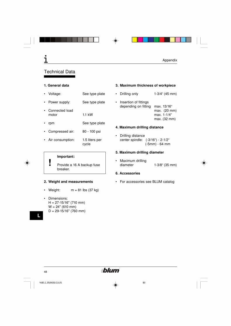
Technical Data
1. General data
• Voltage: See type plate
• Power supply: See type plate
• Connected loadmotor 1.1 kW
• rpm See type plate
• Compressed air: 80 - 100 psi
• Air consumption: 1.5 liters percycle
Important:
Provide a 16 A backup fusebreaker.
2. Weight and measurements
• Weight: m = 81 lbs (37 kg)
• Dimensions:H = 27-15/16" (710 mm)W = 24" (610 mm)D = 29-15/16" (760 mm)
3. Maximum thickness of workpiece
• Drilling only 1-3/4“ (45 mm)
• Insertion of fittingsdepending on fitting max. 13/16“
max. (20 mm)max. 1-1/4“max. (32 mm)
4. Maximum drilling distance
• Drilling distancecenter spindle: (-3/16“) - 2-1/2“ (-5mm) - 64 mm
5. Maximum drilling diameter
• Maximum drillingdiameter 1-3/8“ (35 mm)
6. Accessories
• For accessories see BLUM catalog
%$������0,1,35(66�)$�,G1U���������S�� ����������������$0��

49
L
Appendix
%$������0,1,35(66�)$�,G1U���������S�� ����������������$0��

50
L
Appendix
%$������0,1,35(66�)$�,G1U���������S�� ����������������$0��

51
L
Appendix
%$������0,1,35(66�)$�,G1U���������S�� ����������������$0��

52
L
Appendix
Subject to change without notice! IDNR: 598.608.0BAU0004822774 IDX:01
BA63.02 EN-US / 08.06Printed in Austria
%$������0,1,35(66�)$�,G1U���������S�� ����������������$0��

Änderungen vorbehalten ! Id. Nr. 5986300 Printed in Austria Schema MP FA 3x460V CSA/06.04-tg
MINIPRESS MP FA 3x460V 60Hz
File: Schema MP FA 3x460V CSA.p65
SCHALTSCHEMA / CIRCUIT DIAGRAMSCHÉMA ÉLECTRIQUE / ESQUEMA DE CONEXIONESSCHEMA ELETTRICO / KYTKENTÄKAAVIO
S1 690V IEC, 600V UL/CSA 4552380T1 460V/230V, 15VA 5994850F1, F2 250V, Ø5x20mm, 0,1AT 38092001S2 250V/6A, G1/4" 3988890H1 230VAC 2456160K1 400V (max.690V), 12A 2456300M1 1,1kW, 3x460V 3282959
1 3 5
2 4 6
13
14
K1
A1
A2
1
24
1S2P
File: MP FA 3x460V.FH9
prim: 460V 50/60Hzsek: 230V, 10VA
0,1AT 0,1ATT1
0V 460V
0V 230V
3x460V 60Hz2,3A, 1,1kW,3275 Upm
3x460VU 1 V 1 W 1
W 2 U 2 V 2
1
3
5
2
4
6
S1
7 8
PE
L1
L2
schwarz - black
L3
weiss - white
PEgrün - green
rot - red
H1
3~ M1

Änderungen vorbehalten ! Id. Nr. 5986300 Printed in Austria Schema MP FA 3x460V CSA/06.04-tg
MINIPRESS MP FA 3x460V 60Hz
File: Schema MP FA 3x460V CSA.p65
PNEUMATIKSCHEMA / PNEUMATIC DIAGRAMSCHÉMA PNEUMATIQUE / ESQUEMA DEL CIRCUITO NEUMATICOSCHEMA PNEUATICO / PAINEILMAKAAVIO
0 Gr.3 04740600V G1/8" 17994900Z G1/8", 5µm 39755600Z1 G1/8", DM40, 0-10 43987901A G1/8" 24543841V1 G1/8" 85853651V2 M5 39760001V3 G1/8" 39886001V5 G1/8" 24549701S2 G1/4", 250V/6A 39888902V1 G1/8" 18003302A1 G1/8" 2285329 li/left2A2 G1/8" 2285679 re/right
ø80x105
5 1 3
4 2
1 3
2
1
1
2
P R
A
Y
1A
2A1 2A2
2V1
1Z
1V1
0V
0Z
1V51S2
1V2
p = 6bar(p min = 5bar/p max = 7bar)
File: MP EA Pneumatik.fh9
0-10bar
ø6/4
ø8/6
1V3
1-10 bar / 3 bar
0Z1
ø25x25
ø8/6
ø6/4

Änderungen vorbehalten ! Id. Nr. 5986240 Printed in Austria Schema MP FA 3x220V CSA/06.04-tg
MINIPRESS MP FA 3x220V
File: Schema MP FA 3x220V CSA.p65
SCHALTSCHEMA / CIRCUIT DIAGRAMSCHÉMA ÉLECTRIQUE / ESQUEMA DE CONEXIONESSCHEMA ELETTRICO / KYTKENTÄKAAVIO
S1 690V IEC, 600V UL/CSA 4552380F1, F2 250V, Ø5x20mm, 1,6AT 17887001S2 250V/6A, G1/4" 3988890H1 230VAC 2456160K1 400V (max.690V), 12A 2456300M1 1,1kW, 3x220V 3247969
1 3 5
2 4 6
13
14
K1
A1
A2
1
24
1S2P
File: MP FA 3x220V CSA.FH9
F2 T1,6A F1 T1,6A
3x220V 60Hz4,7A, 1,1kW,3275 Upm
3x220VU 1 V 1 W 1
W 2 U 2 V 2
1
3
5
2
4
6
S1
7 8
PE
L1
L2
schwarz - black
L3
weiss - white
PEgrün - green
rot - red
H1
3~ M1

Änderungen vorbehalten ! Id. Nr. 5986240 Printed in Austria Schema MP FA 3x220V CSA/06.04-tg
MINIPRESS MP FA 3x220V
File: Schema MP FA 3x220V CSA.p65
PNEUMATIKSCHEMA / PNEUMATIC DIAGRAMSCHÉMA PNEUMATIQUE / ESQUEMA DEL CIRCUITO NEUMATICOSCHEMA PNEUATICO / PAINEILMAKAAVIO
0 Gr.3 04740600V G1/8" 17994900Z G1/8", 5µm 39755600Z1 G1/8", DM40, 0-10 43987901A G1/8" 24543841V1 G1/8" 85853651V2 M5 39760001V3 G1/8" 39886001V5 G1/8" 24549701S2 G1/4", 250V/6A 39888902V1 G1/8" 18003302A1 G1/8" 2285329 li/left2A2 G1/8" 2285679 re/right
ø80x105
5 1 3
4 2
1 3
2
1
1
2
P R
A
Y
1A
2A1 2A2
2V1
1Z
1V1
0V
0Z
1V51S2
1V2
p = 6bar(p min = 5bar/p max = 7bar)
File: MP EA Pneumatik.fh9
0-10bar
ø6/4
ø8/6
1V3
1-10 bar / 3 bar
0Z1
ø25x25
ø8/6
ø6/4

Änderungen vorbehalten ! Id. Nr. 632.075.0 Printed in Austria Schema MP FA 1x220V CSA-ATB/07.04-tg
BAU0005694594 IDX00
MINIPRESS MP FA 1x220V
File: Schema MP FA 1x220V CSA-ATB.p65
SCHALTSCHEMA / CIRCUIT DIAGRAMSCHÉMA ÉLECTRIQUE / ESQUEMA DE CONEXIONESSCHEMA ELETTRICO / KYTKENTÄKAAVIO
S1 690V IEC, 600V UL/CSA 4552380F1 250V, Ø5x20mm, 1,6AT 17887001S2 250V/6A, G1/4" 3988890H1 230VAC 2456160K1 400V (max.690V), 12A 2456300M1 1,1kW, 220V/60Hz 3244009C 25µF, 400VDB 2649801
1 3 5
2 4 6
13
14
K1
A1
A2
1
24
1S2P
File: MP FA 1x220V-ATB.FH9
F1 T1,6A
PE
N
L1white
black
PEgreen
T1
T5
T4
T8
L
N
H1
X1
X2
1~ M1
1x220V 60Hz,S6-60%6,5A, 1,48HP, 3420RPMC 25µF 400VDB
C
1
3
5
2
4
6
S1
7 8

Änderungen vorbehalten ! Id. Nr. 632.075.0 Printed in Austria Schema MP FA 1x220V CSA-ATB/07.04-tg
BAU0005694594 IDX00
MINIPRESS MP FA 1x220V
File: Schema MP FA 1x220V CSA-ATB.p65
PNEUMATIKSCHEMA / PNEUMATIC DIAGRAMSCHÉMA PNEUMATIQUE / ESQUEMA DEL CIRCUITO NEUMATICOSCHEMA PNEUATICO / PAINEILMAKAAVIO
0 Gr.3 04740600V G1/8" 17994900Z G1/8", 5µm 39755600Z1 G1/8", DM40, 0-10 43987901A G1/8" 24543841V1 G1/8" 85853651V2 M5 39760001V3 G1/8" 39886001V5 G1/8" 24549701S2 G1/4", 250V/6A 39888902V1 G1/8" 18003302A1 G1/8" 2285329 li/left2A2 G1/8" 2285679 re/right
ø80x105
5 1 3
4 2
1 3
2
1
1
2
P R
A
Y
1A
2A1 2A2
2V1
1Z
1V1
0V
0Z
1V51S2
1V2
p = 6bar(p min = 5bar/p max = 7bar)
File: MP EA Pneumatik.fh9
0-10bar
ø6/4
ø8/6
1V3
1-10 bar / 3 bar
0Z1
ø25x25
ø8/6
ø6/4

Blum, Inc.7733 Old Plank Rd.Stanley, NC 28164toll free 800-438-6788local 704-827-1345fax 704-827-0799internet www.blum.us
Subject to change without notice! IDNR: 598.594.0BAU0004823171 IDX:00
BA63.01 EN-US / 12.03Printed in Austria