back up steering system 2001 - present daimler … up steering system 2001 - present...
TRANSCRIPT

Back Up Steering System 2001 - Present
Daimler-Chrysler Mini VansInstallation Manual and Owner’s Guide
37 Daniel Rd. West, Fairfield, NJ 07004-2521 • 973-808-9709 • FAX 973-808-9713 • E-MAIL: [email protected]
Providing Mobility forthe Physically ChallengedSince 1952
DCBUS Rev 03-09
This manual contains 2001-2008
installation instructions.
2001 - 2007 - Front of book
& general information.
2008 - Instructions for 3.8 and 3.3
engines are in the rear of the manual.
STOP
2
Mobility Dealer and Installing TechnicianCongratulations,
You have just purchased the finest, mostreliable Back-Up Steering system manu-factured. We are offering a 3 year/36,000mile manufacturer’s components warranty– see warranty pages for details. Pleaseread and reread these instructions as im-provements have been made to make yourinstallation easier and the components lastlonger. If you follow the directions step bystep as instructed, you will not encounterany problems and you will have a properinstallation.
If you have any questions call 973-808-9709 between 8 am and4:30 pm, Monday through Friday and ask for technical assistance.
Thank you for supporting Drive-Master Products.
Yours in mobility,
President

3
DEALER WARNINGS1. The back-up system should not be used to take the place of the fac-
tory power steering system.2. Route all hoses to prevent rupture or chafing of back-up and factory
lines and keep away from hot exhaust & manifold components.3. Only trained and certified technicians can install Drive-Master back-
up systems, otherwise the warranty will be void.4. Do not mount back-up steering pump unit with the reservoir ports
facing down towards the ground.5. Flow sensor fittings and wires were specially checked for security
prior to leaving our factory. Take care when installing not to loosenor break wires. To do so will DAMAGE FLOW SENSOR ANDINVALIDATE WARRANTY. Refer to troubleshooting guide for testprocedures
6. Do not make any electrical connections that are different than theDrive-Master wiring instructions.
7. Disassembling components without prior Drive-Master notificationand a valid Return Authorization (RA) in writing by a Drive-Masteroffice liaison will void warranty, and a charge will be issued for anyreplacement parts. DO NOT CUT HARNESS’ WHEN REMOVINGELECTRICAL WIRING FOR RETURN-THIS WILL VOID WAR-RANTY!
8. 2001 through 2005 Daimler/Chrysler minivan products-Check theOEM return line from the cooler to the OEM fill reservoir to see ifthere is a metal restrictor in the line. This can be seen from underhood, right side of motor from reservoir. If there, remove and discardthe line. Replace with the yellow push-lok hose supplied. FAIL-URE TO DO THIS WILL RESULT IN HOSE FAILURE ATTHE COOLER END AND VOID THE WARRANTY!
9. Drive-Master does not have a labor reimbursement program. So, ifyou cannot diagnose the problem in 15 minutes, do not waste anymore time and phone for technical assistance. (973) 808-9709 Mon.- Fri. 8:00AM - 4:30PM EST.

4
Back-Up Steering System Operationfor the owner/user
The Drive-Master Back-Up Steering system is designed to provide emergency powersteering in the event of engine stall or OEM power steering failure. You have a Back-UpSteering System because your OEM steering is modified to low or no effort. The Drive-Master back-up steering pump will automatically activate when the OEM power steeringflow is disrupted. Audible and visual alarms alert the driver of the activation of the back-up steering system. (WARNING: THE ALARM BUZZER WILL STAY ACTIVE AS AREMINDER TO THE DRIVER TO GET OFF THE ROAD AS SOON AS POSSIBLE.STOP AND TURN OFF THE VEHICLE AND SUMMON HELP.)
The Drive-Master Back-Up system will become operational after the vehicle is running.This exclusive feature is accomplished by the Drive-Master back-up module (or relay inthe toggle switch equipped model). Excessive current draw from the battery is eliminat-ed until the engine is started. The back-up system’s operation can be tested two ways:
1. Start the engine. Turn the steering wheel left or right fully to end stops. The sys-tem will engage when the wheel hits the stop. The warning buzzer will sound (ifequipped with buzzer), and the LED will light, alerting the driver of the back-upsystem’s operation.
2. The test/emergency switch can be manually operated from the Drive-Master back-up steering control module (or toggle switch) which overrides the system and acti-vates the back-up steering immediately. Push the button or operate the toggleswitch to the on position - the pump will run. Push the button again or toggle theswitch to off & the pump will turn off.
The flow rate of the back-up steering pump is 3.5 gallons per minute. The system is V.A.tested and accepted. It will operate beyond the 180 second specification required for V.A.clients. The back-up system has its own one quart reservoir, and operates on the vehi-cle’s 12 volt battery.
Maintenance: Maintain normal fluid level in the OEM power steering reservoir. Thisshould be checked when engine oil and filter are changed, every 3000 to 5000 miles.
Leaks: Any dripping or leak detection under vehicle – return to your mobility equip-ment dealer for repairs immediately.
Steering: If steering becomes hard to steer or noisy - return to your mobility equipmentdealer for repairs immediately.
Annually, or every 30,000 miles - Return to your mobility equipment dealer for completesystem check and replacement of the OEM Power Steering fluid in the system.
Continuous Operation: if the BUS motor runs continuously, turn vehicle off immedi-ately and call your dealer for service.
5
DRIVE-MASTERBACK-UP STEERING SYSTEM
LIMITED PARTS ONLY WARRANTY
DRIVE-MASTER warrants that the parts of your new Back-Up Steering System are free from defects in materials orworkmanship for a period of 3 years or 36,000 miles from date of first retail purchase, whichever occurs first.
Return of Warranty Registration CardYour return of the attached Warranty Registration Card within 10 days of your purchase is a condition of per-formance under this Limited Parts-Only Warranty.
What This Warranty Gives You:If your Drive-Master Back-up Steering System is properly operated and maintained, any component covered by this lim-ited warranty found to be defective in materials or workmanship, will be replaced without charge.Under this limited warranty, the sole and exclusive remedy is the replacement of defective parts with new or remanufac-tured parts, within Drive-Master’s sole discretion.NOTE – the cost of labor to install parts provided under this Limited Parts-Only Warranty is not covered by thisLimited Parts-Only Warranty.
This Is Your Only Written WarrantyThis Limited Parts-Only Warranty is the only express warranty applicable to your Back-up Steering System. Drive-Masterdoes not authorize anyone to modify this Limited Parts-Only Warranty or to assume for Drive-Master any other obligationor liability in connection with this Limited Parts-Only Warranty.
Limitation on Implied Warranties and Consequential DamagesAll Implied Warranties, including the implied warranties of merchantability and fitness for a particular use, are limited,to the extent allowed by law, to the time period covered by this Drive-Master New Back-up Steering System LimitedParts-Only Warranty, or to the applicable time period provided by state law, whichever period is shorter.
Drive-Master is not responsible for any time that you lose, for any inconvenience you might be caused, for any commer-cial loss, for the cost of alternative transportation or hotels, or for any other incidental or consequential damages you mayincur.
Some states do not permit a limitation on how long an Implied Warranty will last, or the exclusion or limitationof incidental or consequential damages, so the above limitation and exclusion may not apply to you.
This Warranty gives owners specific legal rights, and they may also have other rights that vary from state to state.
What Is Not Covered under this Limited Parts-Only Warranty
– Damage caused by accident or misuse or abuse
– Alteration, tampering or modification of the Back-up Steering System
– Claims involving disconnection or alteration of the vehicle odometer, or where the actual vehicle mileage cannototherwise be determined
– Damage caused by failure to maintain or improper maintenance of the Back-up Steering System
See your Owner Maintenance section for proper maintenance of your Back-up Steering System.We recommend servicing at qualified NMEDA dealers. Make sure your service location fills out the maintenance recordin your owners manual so you will have a means to demonstrate that proper service has been performed.
– Other items and conditions not covered by this limited warranty– Non - Drive-Master parts– Normal wear and tearHow To Make A ClaimContact Drive-Master at the following address and telephone:37 Daniel Rd. West, Fairfield, NJ 07004 - 973-808-9709Return of defective parts may be a condition of claim approval.We suggest that you use mobility dealers who are members of the National Mobility Equipment Dealers Association(NMEDA). See www.nmeda.org or call us at 973-808-9709 and ask for the closest dealer.

6
Parts ListBack-Up Steering Kit
2001 and up Daimler Chrysler Minivans1 Back-Up Steering pump and motor assembly
1 Back-Up Steering solenoid
1 24" 2 Gauge Red with lugs - used between solenoid and the battery
1 48" 2 Gauge Red with lugs - used between solenoid and the back-up Steering pump
1 65" 2 Gauge Black with lugs - used between pump bracket and negative battery terminal
1 12" 4 Gauge Black with lugs - used between the battery negative and body ground point(ground strap)
1 25" High Pressure Hose with BLUE marking - compression side for OEM power steering
1 33" High pressure Hose – used between back-up Steering pump and shuttle-flow sensorassembly
1 54" High Pressure Hose with RED marking - compression side for rack high pressure
1 66-1/2" PUSH-LOK Hose - used between T assembly and the back-up Steering low pres-sure canister
1 24" x 3/8" PUSH-LOK Hose – used between the OEM reservoir and low pressure cooler line
1 T Assembly 3/4"x1/2"x3/4"
1 Shuttle valve-flow sensor assembly - Flow sensor marked BLUE. Shuttle valve marked RED
1 2 Piece Shuttle valve-Flow sensor assembly bracket with 1/4" – 20 x 1-3/4" bolts and 1/4" x20 lock nuts
1 1/4" x 20 x 1-1/4" bolt with lock nut – used for hood prop bracket
2 1/4" x 3/4" hex head self-tapping screws – used for mounting solenoid
1 Back-Up Steering Control module with wiring harness
2 #6 hose clamps
2 #12 hose clamps
>For Daimler Chrysler service bulletin 19-004-03 if necessary
1 33-1/2" Yellow PUSH-LOK hose
2 #6 hose clamps
1 Warning Label
1 Warranty Registration Mailing Card
1 Consumer User/Warranty Book

7
1. Open hood for access to engine compartment.
2. Disconnect the OEM battery.
3. Remove both headlights.
4. Remove the front bumper clip.
5. Remove the wiper arms. (2001 - 2007 only)
6. Remove the wiper cowl. (2001 - 2007 only)
7. Disconnect the wiper fluid tube and the wiper power plug, then remove the lower wipercowl assembly. (2001 - 2007 only)
8. Cut the OEM high pressure line as shown. This cut should be made with a tubing cutterand should not be cut where the lines bend.
9. Drain the OEM power steering fluid while you work on the rest of the install.
High Pressure Cut
Cut lineshown, highpressure lineto rack

8
10. Locate the center point on the top of the front bumper and mark it.This will be the center point for the back-up steering pump bracket.
11. Make sure to protect the radiator while drilling and bolting the back-up steering pump. A 1/4" spacer can be used to space the back-upsteering pump away from the radiator while installing.
12. Bolt on the back-up steering pump. Use the 5/16 hole in pump hous-ing marked GRD to connect the 48” #2 black ground cable. The otherend is to be connected to the negative terminal on battery. Failure todo so can cause poor or no operation of pump and damage to thevehicle & causes High Pressure hose to short out & seperate (Seeinset below).
13. Remove plug in reservoir and using a funnel, fill with new cleanOEM Power Steering Fluid. Reinstall plug.
Low and high pressure installed on B.U.S. pump

9
14. Remove the OEM low pressure hose located between the OEMpower steering reservoir and the OEM low pressure line going to thepower steering cooler.
15. Install the provided 3/8" PUSH-LOK hose between the OEM reser-voir and the OEM low pressure cooler line. #6 Hose clamps shouldbe used to secure the PUSH-LOK hose.
Remove OEM low pressure line

10
16. The T assembly can now be installed as shown in this picture. (Alsosee step #18.) This picture is to demonstrate location of the T assem-bly. Cut 3" out of the OEM fill line and insert the T assembly withthe 1/2" barbed fitting facing slightly downward.
17. Use the #12 hose clamps to secure the T assembly.
T inserted into OEM low pressure fill line

11
18. Attach the 1/2" gray PUSH-LOK hose to the T fitting. IMPOR-TANT!!!! This 1/2" PUSH-LOK line must slope downward towardthe back-up steering pump. This must be a continuous straight slope,no rises as it will trap air in the system.
T insert with push lok hose
Slope downwardtowards bus pump

12
19. Attach the remaining side of the 1/2" PUSH-LOK hose to the back-up steering pump’s 1/2" barbed fitting.
20. Install the 33" high pressure hose using Teflon tape. Install one endinto the high pressure output side of the back-up steering pump.
Back-up Steering Pump with hoses

13
Shuttle-flow Valve Assembly
Shuttle valve and flow sensor assembly

14
21. Insert the remaining end of the high pressure line from the back-upsteering pump into the shuttle valve-flow sensor input fitting.
High pressure line attached to shuttle-flow assembly
15
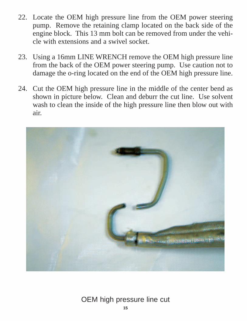
22. Locate the OEM high pressure line from the OEM power steeringpump. Remove the retaining clamp located on the back side of theengine block. This 13 mm bolt can be removed from under the vehi-cle with extensions and a swivel socket.
23. Using a 16mm LINE WRENCH remove the OEM high pressure linefrom the back of the OEM power steering pump. Use caution not todamage the o-ring located on the end of the OEM high pressure line.
24. Cut the OEM high pressure line in the middle of the center bend asshown in picture below. Clean and deburr the cut line. Use solventwash to clean the inside of the high pressure line then blow out withair.
OEM high pressure line cut

16
25. Clean the end of the cut. Bend the OEM line into more of a U-shape.Use EXTREME CAUTION not to kink the line.
26. Place the line in a vice and slightly twist the line so it will lay flat onthe bench.
OEM high pressure line bend

17
27. Locate the 25" BLUE High pressure hose and attach the compressionside to the OEM high pressure line.
28. Make sure the O-ring is still present and reinstall the modified OEMhigh pressure line with the line facing upward and toward the front ofthe vehicle.
OEM high pressure line removed

18
29. Locate the 54" RED High pressure line and attach the compressionside to the input line going to the rack.
View from under vehicle
High pressure line to rack

19
30. Apply Teflon tape on the RED marked high pressure line and installinto the shuttle valve marked with RED.
31. Apply Teflon tape on the BLUE marked pressure line and install intothe flow sensor.
High pressure line installed

20
32. Add the ground strap from the negative battery terminal to a cleanedground point.
33. Mount the back-up steering solenoid as shown, utilizing the OEMhole in the cross member and the screws provided.
Attach ground strap

21
34. The bracket for the shuttle-flow valve assembly needs to be securedunder the hood prop bracket. Use the 1/4"-20 bolt and lock nut tothrough bolt the hood prop bracket with the shuttle-flow bracket(studded bracket).
35. Install the top plate with the bolts provided to secure the shuttle-flowassembly.
36. Install wire harness and wire per diagram.
37. With all the fittings secured and tightened you can now fill the sys-tem according to the fill instructions.
Shuttle-flow bracket

22
PREFERRED FILLING INSTRUCTIONSWARNING: The fluid level should be checked with engine off to prevent injury from moving components.
CAUTION: Mopar® Power Steering Fluid +4 or Mopar® ATF+4 Automatic Transmission Fluid is to be used inthe power steering system. Both fluids have the same material standard specifications (MS-9602).No other power steering or automatic transmission fluid is to be used in the system. Damage mayresult to the power steering pump and system if another fluid is used. Do not overfill the system.
CAUTION: If the air is not purged from the power steering system correctly, pump failure could result.
NOTE: Be sure the vacuum tool used in the followingprocedure is clean and free of any fluids.
1. Check the fluid level. As measured on the side of the
reservoir, the level should indicate between MAX and
MIN when the fluid is at normal ambient temperature.
Adjust the fluid level as necessary. (Refer to 19 -
Steering/Pump/FLUID - Standard (Procedure).
2. Tightly insert Power Steering Cap Adapter (4), Special
Tool 9688, into the mouth of the reservoir (3).
CAUTION: Failure to use a vacuum pump reservoir (1) may allow power steering fluid to be sucked into the hand
vacuum pump.
3. Attach Hand Vacuum Pump (2), Special Tool C-4207 or equivalent, with reservoir (1) attached, to the Power Steering Cap
Adapter (4). Call 973-495-6182 Mactools. Ask for Kevin O’Malley. He has offered us special pricing for the tool and reservoir
adapter M4000 Pump and MIL9688 Adapter
CAUTION: Do not run the engine while vacuum is applied to the power steering system.Damage to the power steering pump can occur.
NOTE: When performing the following step make sure the vacuum level is maintained during the entire time period.
4. Using Hand Vacuum Pump (2), apply 68-85 kPa (20-25 in. Hg) of vacuum to the system for a minimum of three minutes.
5. Slowly release the vacuum and remove the special tools.
6. Adjust the fluid level as necessary. Refer to Step #1.
7. Repeat Step #1 through Step #6 until the fluid no longer drops when vacuum is applied.
8. Start the engine and cycle the steering wheel lock-to-lock three times.
NOTE: Do not hold the steering wheel at the stops.

23
38. After filling, bleeding, and running the system, BEFOREre-assembling the OEM vehicle body parts, run the vehicle toOEM operating temperature. Operate the Back-up steering sys-tem six to twelve times. Check the OEM reservoir for properfluid level. Re-check all of your hydraulic connections for clean,dry, fittings with no leaks.
39. WIRING SYSTEM CHECK: Check wire connections from thecontrol module
Green = Power + key offOrange = Power + ignition onRed = Flow SensorWhite = Solenoid trigger post#2 Red = Positive battery terminal to solenoid
(see diagram)#2 Wire = Positive from solenoid to
Drive-Master back-up steering pump
40. Verify system operation with engine failure:
a. Pull out fuel pump relay while engine is running
b. When engine stalls, Drive-Master back-up steering system willactivate
41. Affix the warning label to the inside of the vehicle within view ofthe customer. Instruct customer of it’s placement
42. Fill out warranty protection card. Have customer sign and returnmail to Drive-Master to register the equipment.
43. Explain the system to your customer and give him the suppliedDrive-Master Back-Up owner’s manual

24
Drive-Master Back-Up Steering SystemTroubleshooting Guide
Do the diagnostics before you call 973-808-9709 anddouble check your wire connections. Mon. - Fri.8:00 AM - 4:30 PM EST.
IF BACK-UP PUMP DOES NOT COME ON LOCK-TO-LOCK:Check green wire connected to the battery side of thesolenoid (positive power) with key off.Check orange wire positive power with ignition on.With ignition off, cut ungrounded wire at the flowsensor. Check continuity through flow sensor. Nocontinuity means a bad flow sensor.
IF CONTROL MODULE DOES NOT TURN BACK-UP SYSTEM ON:With ignition on, ground out the red wire from thegray harness. The back-up pump should activate. Ifno activation, check pin connectors in the controlmodule plug. If pin connectors are correct the con-trol module is bad.
25
BACK-UP PUMP
FLOW SENSOR
RELAY
GROMMET
SOLENOID
BATTERY
OR
TOGGLE
L.E.D
WT
RD
WT
WTGN
BK
PK2
PK1
RD
10 A
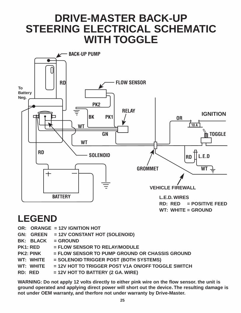
DRIVE-MASTER BACK-UPSTEERING ELECTRICAL SCHEMATIC
WITH TOGGLE
LEGENDOR: ORANGE = 12V IGNITION HOTGN: GREEN = 12V CONSTANT HOT (SOLENOID)BK: BLACK = GROUNDPK1: RED = FLOW SENSOR TO RELAY/MODULEPK2: PINK = FLOW SENSOR TO PUMP GROUND OR CHASSIS GROUNDWT: WHITE = SOLENOID TRIGGER POST (BOTH SYSTEMS)WT: WHITE = 12V HOT TO TRIGGER POST V1A ON/OFF TOGGLE SWITCHRD: RED = 12V HOT TO BATTERY (2 GA. WIRE)
WARNING: Do not apply 12 volts directly to either pink wire on the flow sensor. the unit is ground operated and applying direct power will short out the device. The resulting damage is not under OEM warranty, and therfore not under warranty by Drive-Master.
L.E.D. WIRESRD: RED = POSITIVE FEEDWT: WHITE = GROUND
VEHICLE FIREWALL
IGNITION
RDToBatteryNeg.


27
Solenoid Wiring DiagramsNew type solenoids can be used on new or old
back-up systems. Systems using a hot fired solenoidchanged approximately Oct. 2003 to ground fired.
Ground FiredSolenoid
Hot FiredSolenoid
Top View
Motor
White
White
Battery +
Motor Battery +
MountingBracket
Jumper
MountingBracket

28
2008 Dodge/Chrysler Parts ListAll Engines.
1 - 43” high pressure hose red end.
1 - 43” high pressure hose blue end.
1 - 43” 1/2 gray push-lock hose.
1 - 44” red #2 battery cable.
1 - 24” red #2 battery cable.
1 - 48” black #2 ground cable.
1 - 12” black #2 ground cable.
Pump with flow sensor, shuttle valve, bracket and elbow installed.
1 - “T” 1⁄2” x 5⁄8”.
2 - #12 hose clamps.
1 - Solenoid bracket with 2 - 10⁄32” nuts, bolts and washers.
1 - 1⁄2” x 3⁄8” push-lock barb.
2 - 3⁄8” bolts - 21⁄2” long with nuts and washers.
1 - Control module & cable.
1 - 10 Amp circuit breaker
Various electrical connectors.
29
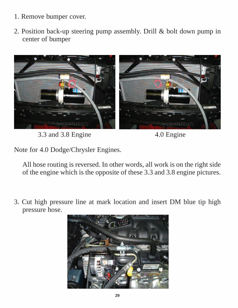
1. Remove bumper cover.
2. Position back-up steering pump assembly. Drill & bolt down pump incenter of bumper
3. Cut high pressure line at mark location and insert DM blue tip highpressure hose.
Note for 4.0 Dodge/Chrysler Engines.
All hose routing is reversed. In other words, all work is on the right sideof the engine which is the opposite of these 3.3 and 3.8 engine pictures.
3.3 and 3.8 Engine 4.0 Engine

30
4. Cut OEM high pressure line at mark location. Insert DM red tip highpressure hose.
4. Cut hose from reservoir to OEM P.S. pump at mark location.
5. Install T.

Tee installed
7.Install solenoid using OEM bolt as shown.
After this step go to Fill & Complete Installation pg. 24.
31

32
NUMBER: 19-004-03
GROUP: Steering
DATE: Aug. 29, 2003
This bulletin is supplied as technical information only and is not an authorization for repair. No part of this publication may be reproduced, stored in a retrieval system,or transmitted, in any form or by any means, electronic, mechanical, photocopying, or otherwise, without written permission of DaimlerChrysler Corporation.
THIS BULLETIN IS BEING PROVIDED IN ADVANCE. DO NOT ORDER PARTS ORPERFORM ANY ACTIONS RELATED TO THIS BULLETIN UNTIL SEPT. 8, 2003.
THIS BULLETIN SUPERSEDES SERVICE BULLETIN 19-006-02, DATED MAY 20,2002, WHICH SHOULD BE REMOVED FROM YOUR FILES. ALL REVISIONS AREHIGHLIGHTED WITH **ASTERISKS**. THE REVISION INCLUDES A REVISEDPART NUMBER AND ADDED RIGHT HAND DRIVE VEHICLES.
SUBJECT:Steering Shudder
OVERVIEW:This bulletin involves replacing one of the two power steering cooler hoses with a new longer powersteering hose.
MODELS:
2001-2001 (RS) Town & Country, Caravan, Voyager
2001-2002 (RG) Chrysler Voyager (International Markets)
NOTE: This bulletin applies to **right hand and** left hand drive vehicles equipped with a3.3L or 3.8L engine.
SYMPTOM/CONDITION:A shudder (vibration) is felt inside the vehicle while turning the steering wheel at idle or during lowspeeds such as a parking lot maneuver. The shudder may be felt in the steering wheel, seat,and/or body.
DIAGNOSIS:To verify the condition, perform stationary turns and/or low speed turns in drive and reverse.Perform the evaluation with the A/C in the on and off position. If steering shudder is detected, per-form the Repair Procedure.
PARTS REQUIRED:
Qty. Part No. Description
AR **05135964AA** 11/32" Hose, Bulk Power Steering Return
AR NPN 5/8" or 11/16" Convolute Tubing
2 04856501 Tie Strap
DaimlerChrysler CorporationDealer: Technical Operations
SERVICEBULLETIN

33
19-004-03REPAIR PROCEDURE:1. Cut 850 mm (33.5 in.) of power steering hose (p/n 05135964AA) or equivalent.2. Cut 790 mm (31 in.) of 15.9mm (5/8 in.) or 17.5 m (11/16 in.) convolute tubing. Place the con-
volute tubing around the power steering hose.3. Open hood and remove the power steering reservoir cap.4. Raise the vehicle on an appropriate hoist.5. Locate the power steering cooler attached to the crossmember support. Remove the forward
(closest to front of vehicle) hose from the cooler and tube. Drain the power steering fluid in anappropriate container.
6. Remove the two tension clamps from the removed hose and install on the new power steeringreturn hose.
7. Install the new hose and tension clamp onto the power steering cooler.8. Wrap the hose clockwise around the perimeter and on top of the power steering cooler as
shown in (Fig 1). Install the hose and tension clamp to the power steering return tube.
Fig. 1 HOSE ROUTING - STANDARD COOLER ON LEFT. H/D COOLER ON RIGHT.
1 - COOLER RETURN TUBE (CLOSEST TO FRONT OF VEHICLE)
2 - RETURN TUBE TO RESERVOIR
3 - CROSSMEMBER SUPPORT
4 - TIE STRAP LOCATIONS
5 - POWER STEERING COOLER
6 - POWER STEERING COOLER HOSE (ROUTE CLOCKWISE)
9. Use two tie straps to strap the return hose to the power steering cooler and pressure steeringhose shown in (Fig. 1).
10. Lower vehicle and open hood.11. Fill the power steering reservoir to the proper level using lo pour hydraulic

34
19-004-0312. For Proper fluid fill and bleeding air form the power steering system:
a. Start engine and let run for a few seconds, then turn off engine.b. Check fluid level and add if necessary. Repeat the above steps until the fluid level remains
constant after running the engine.c. Raise the front wheels off the ground.d. Start engine, and slowly turn the steering wheel lightly contacting the left and right stops.e. Stop the engine and check fluid level. Add fluid if necessary.f. Lower vehicle, start engine and slowly turn steering wheel lock-to-lock.g. Stop engine and check fluid level. Add fluid if necessary.h. If fluid is extremely foamy, allow vehicle to stabilize a few minutes, then repeat the above
procedure.13. Evaluate the vehicle for power steering shudder. If shudder still exist, instruct the operator that
the vehicle may have to be driven for up to 200 miles before all air is purged rom the powersteering system.

35
OE
MR
esev
oir
OEM
Pum
p
OE
MLo
w P
ress
ure
Ret
urn
OE
MS
uppl
yH
ose
OE
MC
oole
r
OE
MH
P L
ine
Com
pres
sion
Fitt
ing
Com
pres
sion
Fitt
ing
DM
HP
Lin
e
Red
HP
Lin
e
Blu
e H
P L
ine
Shu
ttle
Val
ve
Flo
w S
enso
r
DM
1/2
Sup
ply
Hos
e (G
ray)
DM
B
ack-
up P
ump
Nor
mal
Flo
w
Bac
k-U
p flo
w
3/4
x 1/
2 x
3/4
Tee
Rac
k
Stee
ring
Sys
tem
Flo
w C
hart
200
1 -
Pre
sent

37 Daniel Rd. West, Fairfield, NJ 07004-2521 • 973-808-9709 • FAX 973-808-9713 • E-MAIL: [email protected]