backfilling of deposition tunnels, block alternative · working report 2006-89 backfilling of...
TRANSCRIPT

P O S I V A O Y
FI -27160 OLKILUOTO, F INLAND
Tel +358-2-8372 31
Fax +358-2-8372 3709
Pau la Keto
Pau l - E r i k Rönnqv i s t
March 2007
Work ing Repor t 2006 -89
Backfilling of Deposition Tunnels,Block Alternative

March 2007
Working Reports contain information on work in progress
or pending completion.
The conclusions and viewpoints presented in the report
are those of author(s) and do not necessarily
coincide with those of Posiva.
Pau la Keto
Saan io & R iekko la Oy
Pau l - E r i k Rönnqv i s t
For tum Nuc lea r Se rv i ces Oy
Work ing Report 2006 -89
Backfilling of Deposition Tunnels,Block Alternative

BACKFILLING OF DEPOSITION TUNNELS: BLOCK ALTERNATIVE
ABSTRACT
This report presents a preliminary process description of backfilling the deposition
tunnels with pre-compacted blocks consisting of a mixture of bentonite and ballast
(30:70). The process was modified for the Finnish KBS-3V type repository assuming
that the amount of spent fuel canisters disposed of yearly is 40. Backfilling blocks
(400 x 300 x 300 mm) are prepared in a block production plant with a hydraulic press
with an estimated production capacity of 840 blocks per day. Some of the blocks are
modified further to fit the profile of the tunnel roof. Prior to the installation of the
blocks, the deposition tunnel floor is levelled with a mixture of bentonite and ballast
(15:85). The blocks are placed in the tunnel with a modified reach truck. Centrifugal
pellet throwing equipment is used to fill the gap between the blocks and the rock surface
with bentonite pellets. Based on a preliminary assessment, the average dry density
achieved with block backfill is sufficient to fulfil the criteria set for the backfill in order
to ensure long-term safety and radiation protection. However, there are uncertainties
concerning saturation, homogenisation, erosion, piping and self-healing of the block
backfill that need to be studied further with laboratory and field tests. In addition,
development efforts and testing concerning block manufacturing and installation are
required to verify the technical feasibility of the concept.
Keywords: block backfill, process description, block pressing, installation, pellets,
density criteria

SIJOITUSTUNNELIEN TÄYTTÖ ESIPURISTETUILLA TÄYTEAINELOHKOILLA
TIIVISTELMÄ
Tämä raportti esittää alustavan prosessikuvauksen sijoitustunnelien täytöstä esipuriste-
tuilla täyteainelohkoilla, jotka koostuvat bentoniitin ja murskeen seoksesta (30:70).
Täyttöprosessi muokattiin sopivaksi suomalaiselle KBS-3V tyypin loppusijoitustilalle
olettaen että vuosittain sijoitettavien polttoainekapselien määrä on 40. Täyteainelohkot
(400 x 300 x 300 mm) valmistetaan blokkien puristuslaitoksessa hydraulisella puristi-
mella, jonka arvioitu tuotantoteho on 840 blokkia per päivä. Osa täyteainelohkoista
muokataan sopimaan tunnelin holvin muotoon. Ennen lohkojen asentamista sijoitustun-
nelin lattia tasataan bentoniitin ja murskeen seoksella (15:85). Täyteainelohkot asennet-
taan tunneliin modifioidulla kurotustrukilla. Bentoniittipelletit asennetaan lohkojen ja
tunnelin seinämän väliseen tilaan pellettilingolla. Alustavan arvion mukaan blokkitäy-
töllä saavutettava keskimääräinen täyteainetiheys on riittävä verrattuna täytölle asetet-
tuihin kriteereihin koskien pitkäaikaisturvallisuutta ja säteilysuojelua. Konseptin toimi-
vuuteen liittyvät epävarmuustekijät koskevat lohkotäytön saturaatiota, homogenisaatio-
ta, eroosiota, virtauskanavien muodostumista ja sulkeutumista vaatien lisätutkimuksia
sekä laboratorio- että kenttämittakaavassa. Myös konseptin teknisen toteutettavuuden
todentaminen vaatii kehitystyötä ja testaamista.
Avainsanat: lohkotäyttö, prosessikuvaus, lohkojen puristus, asennus, pelletit, tiheyskri-
teerit

1
TABLE OF CONTENTS
ABSTRACT
TIIVISTELMÄ
1 INTRODUCTION................................................................................................... 3
2 DESIGN BASES FOR BACKFILLING OF DEPOSITION TUNNELS.................... 7
3 BACKFILLING MATERIALS.................................................................................. 9
4 OPERATIONS ABOVE GROUND....................................................................... 13 4.1 Manufacturing backfilling blocks ................................................................ 13
4.1.1 Block dimensions............................................................................ 13 4.1.2 Overall description of block pressing plant ..................................... 14 4.1.3 Process description ........................................................................ 17 4.1.4 Quality control................................................................................. 19
4.2 Other above ground facilities ..................................................................... 19 4.3 Logistics ..................................................................................................... 20
5 INSTALLATION OF BACKFILL MATERIALS...................................................... 21 5.1 Preparations............................................................................................... 21
5.1.1 Dismantling of tunnel infra .............................................................. 21 5.1.2 Levelling of deposition tunnel floor ................................................. 21
5.2 Logistics ..................................................................................................... 22 5.3 Installation of blocks................................................................................... 23 5.4 Installation of pellet fill ................................................................................ 25 5.5 Timing of operations................................................................................... 26 5.6 Need for personnel & equipment ............................................................... 28 5.7 Quality control ............................................................................................ 28
6 ASSESSMENT OF THE DESCRIBED BACKFILLING CONCEPT..................... 29
7 SUMMARY .......................................................................................................... 31
REFERENCES ............................................................................................................. 33
LIST OF APPENDICES................................................................................................ 35

2

3
1 INTRODUCTION
In the previous plans for the Finnish repository (Kirkkomäki 1999, Kukkola 2004,
Saanio et al. 2004), the deposition tunnels were assumed to be backfilled with a mixture
of bentonite and crushed rock compacted in the tunnel on site. Due to the expected
difficulties in compacting the material to a high enough density with the in situ
technique, especially near the roof section, a joint Posiva-SKB project “Backfilling and
Closure of the Deep repository” was launched to develop backfill materials and methods
and to assess alternative backfilling concepts (Gunnarsson et al. 2004). Based on the
assessment, two main alternatives were chosen for the next research phase; the old
concept based on in situ compaction, and a new concept based on backfilling the
deposition tunnel with pre-compacted blocks. Since both the concepts include multiple
material variations, the main difference between the concepts is the compaction method.
The objectives of this report are to:
- Describe the backfilling process based on the block concept
- Adapt the concept to Finnish repository conditions
- Integrate the backfilling process into other repository operations
This process description is mainly based on the work performed in the Posiva-SKB
backfilling project. However, the adaptation to and the integration of the backfilling
concept into the Finnish repository are covered in this report. The preliminary design
(stage I) for the spent nuclear fuel repository in Olkiluoto (Saanio et al. 2004) is used as
background material for this report.
The Finnish repository consists of access routes (ramp & shafts), central tunnels,
deposition tunnels and auxiliary facilities (Saanio et al. 2004). The main part of the
repository will be built at a depth of 420 m (one-layer design), and in case the repository
consists of two storeys (two-layer design), another repository level will be built at a
depth of 520 m (Kirkkomäki 2004). The total excavation volume of the repository is
1.3-1.4 Mm3 and the repository is constructed in several stages (Saanio et al. 2004,
Kirkkomäki 2004). The total amount of spent nuclear fuel to be disposed of is 5 800 tU
and the total number of canisters is nearly 3 000 (Saanio et al. 2004). The distance
between the canisters in the deposition tunnels is 8.6 m (canisters from Loviisa plant)
and 11 m (canisters from Olkiluoto plant) (Saanio et al. 2004). The average distance
between the canisters is approximately 10 m and this distance is used in this report as a
starting value for timing of the operations. The deposition of spent nuclear fuel will start
in 2020 and will continue until the first quarter of the next century (Saanio et al. 2004).
This process description concerns backfilling of deposition tunnels. Backfilling and
sealing of other repository facilities is optimised in later investigation projects. At
present, the assumption is that the other facilities will be backfilled in the same manner
as the deposition tunnels.
The length of one deposition tunnel is approximately 300 m (Saanio et al. 2004). The
total number of deposition tunnels in one-layer design is 137 and the total length is
41 km (Kirkkomäki 2004). For the two-storey design, the values are 150 and 44.7 km

4
(Kirkkomäki 2004), respectively. The theoretical cross-section area of a deposition
tunnel is 14 m2 (see Figure 1-1) (Saanio et al. 2004) and the excavation tolerance is
200 mm (Kirkkomäki 2004). In previous estimations it has been assumed, that the
average over break that can form in careful drill & blast excavation is +8% of the
theoretical cross-section (14 m2 + 8% 15.1 m
2). The 8% is the average over break
determined on the basis of the accuracy of the drilling equipment for the repository
facilities in general, and the absolute value depends on the size of the tunnel. The
smaller the tunnel, the higher the over break percentage. Since the deposition tunnels
are relatively small, it is assumed that the average over break is + 100 mm (half of the
maximum +200 mm, that can occur only in the furthest point of an excavated round),
which leads to an average cross-section of 15.42 m2, that is approximately 10% larger
than the theoretical cross-section 14 m2 (see Figure 1-2). The total volumes of the
deposition tunnels determined for the one and two-level designs are calculated in Table
1-1. The total volume of the deposition tunnels is a little less than half of the total
volume of the repository.
Figure 1-1. The cross-section of a deposition tunnel. The excavation tolerance is
200 mm (Kirkkomäki 2004).

5
Figure 1-2. Cross-section area of the deposition tunnel, Atr = area of the theoretical
cross-section (inner solid line), A100 = area of the theoretical cross-section + 100 mm
(dashed line) and A200 = area of the theoretical cross-section + 200 mm (outer solid
line). Figure: Paula Pohjanperä/Saanio & Riekkola Oy.
Table 1-1. Total volume of the deposition tunnels. The theoretical volume is calculated
based on the theoretical cross-section area. The other total volume given is calculated
assuming that the average over break is 100 mm, leading to a cross-section
approximately 10% higher than the theoretical one.
Totaltunnellength (m)
Theoretical cross-section area (m2)
Theoretical total volume (m3)
Cross-section area with 100 mm over break (m2)
Total volume with 100 mm over break (m3)
One-level design 41 000 14 574 000 15,42 632 220 Two-level design 44 700 14 625 800 15,42 689 274

6

7
2 DESIGN BASES FOR BACKFILLING OF DEPOSITION TUNNELS
The requirements set for backfilling of deposition tunnels have been determined on the
basis of Finnish (YVL Guide 8.4) and Swedish regulations (SKB 2005). The backfill is
a part of the engineered barrier system and its main function is to maintain the
multibarrier principle by sustaining the barrier safety functions (Gunnarsson et al.
2006). Based on general system requirements for a KBS-3 repository, the following
subsystem requirements concerning nuclear safety, radiation protection, environmental
impact, flexibility and efficiency have been determined for backfilling the deposition
tunnels in a KBS-3V type repository (Gunnarsson et al. 2006):
The backfill shall restrict advective transport in deposition tunnels so that the
function of the bedrock is not impaired
The backfill in deposition tunnels shall restrict the upward swelling/expansion of
the buffer so that the function of the buffer is not impaired
The backfill shall not in other ways significantly impair the safety functions of the
barriers
The backfill shall be long-term resistant and its functions shall be preserved in the
expected environment of the repository
The backfill shall be based on a well-proven or tested technique
The backfill properties shall be controlled against specified acceptance criteria
The backfill shall be efficient in terms of consumption of raw material and energy
Installation of backfill shall be possible at a specified rate.
The backfill shall be cost-efficient (Gunnarsson et al. 2006).
The above subsystem requirements have been converted into measurable and/or
calculable quantities referred to as function indicator criteria (see Table 2-1). These
criteria must be fulfilled in the expected repository conditions regardless of different site
and design related constraints. To enable the design of the backfill concept, the function
indicator criteria have been modified further for the current phase of backfill design
(Gunnarsson et al. 2006). Since the functions of different candidate backfill materials
depend on their dry density, density criteria have been determined for these materials
(see Table 2-1). The density criteria are based on current knowledge and will be updated
at future research phases.
In addition to the requirements presented above, there are some additional practical
requirements that need to be taken into account at the different steps of the backfilling
process:
- The backfill operation shall be designed so that the buffer does not swell and intrude
into the tunnel during the installation phase. This pertains to the backfilling of the
upper part of the deposition hole.
- Operational safety shall be ensured at all working stages.
- Backfilling blocks shall be manufactured in mass production to specifications and
quality requirements.
- Installation of the backfill shall be reliable and effective.

8
Table 2-1. Criteria set for backfilling of deposition tunnels (Gunnarsson et al. 2004, 2006, Johannesson & Nilsson 2006). The dry density criteria are valid for saturated
backfill material consisting of a mixture of bentonite and ballast (30:70). The density
criteria were determined based on laboratory tests by Johannesson & Nilsson (2006)
and they may be updated based on further investigations at Baclo phase 3.
Function indicator criteria
Modified function indicator criteria set for the current backfill design
Dry density criteria (kg/m3)
To restrict advection of groundwater the hydraulic conductivity shall be less than 10-10 m/s
The hydraulic conductivity of the backfill shall be less than 10-10 m/s assuming groundwater salinity is 3.5%.
1 700 – 1 890
The swelling pressure should be at least 0.1 MPa to prevent groundwater flow
Swelling pressure should be at least 0.2 MPa (with 3.5% salinity) in order to prevent groundwater flow along the disposal tunnels and to:
1) Maintain the contact between the rock and the backfill tight.
2) Seal off possible erosion induced piping channels after the backfill has reached full saturation (self-healing ability).
3) Lead to homogenisation of the density over the total cross-section of the disposal tunnel.
1 730 – 1 800
To prevent loss of buffer density the compression modulus shall be at least 10 MPa
The compressibility of the backfill shall be low enough to prevent loss of buffer density (Gunnarsson et al. 2006).
For the current backfill design (Gunnarsson et al. 2006) it was determined that the compression of the backfill caused by the swelling of the buffer in the deposition hole should not be so large that the saturated density of the buffer at the top of the canister is lower than 1,950 kg/m3.
In the Swedish design there is a 1.45 m thick layer of buffer material above the canister. In the Finnish deposition hole the distance from the top of the topmost buffer block to the top of the canister is 2 m (Saanio et al. 2004). In addition there is a 20 cm thick cap structure between the buffer and the backfill. However, the same requirement (1.95 t/m3 at the depth of 1.45 m) is also applied to the Finnish case.
1 690
9
3 BACKFILLING MATERIALS
The backfill materials considered in this report are a mixture of bentonite and crushed
rock from Olkiluoto, and bentonite pellets. The other backfilling material alternatives
considered in the joint Posiva-SKB programme “Backfilling and Closure of the Deep
Repository, Baclo”, Asha 230 – bentonite and Friedland-clay - are excluded from this
report. Should the backfill consist 100% of clay, the amounts of handled material and
the size of the storage areas would differ from what is presented in this report.
It is assumed that almost the whole theoretical cross-section (14 m2) is backfilled with
blocks with a dry density of 2.2 t/m3 and a bentonite content of 30 w-% (see Figures 5-1
& 5-2 in Chapter 5). The density of the blocks was determined based on block
compaction tests performed in Germany at the second phase of the Baclo programme
(Gunnarsson et al. 2006). In these tests, the resulting bulk density of the blocks was
2.4 t/m3 with a water content of 7.5-8%. The floor is assumed to be levelled with a
mixture of bentonite and crushed rock with a total dry density of 1.95 t/m3 and a
bentonite content of 15%. The remaining free space is assumed to be filled with
bentonite pellets with a total dry density of 1.3 t/m3 (Kennedy et al. 2002).
The bentonite recommended is high-quality Ca- or Na-bentonite with a smectite content
higher than 70%. The bentonite used in the mixture should be milled into powder form
to provide better homogeneity for the mixture. It is assumed that the bentonite is
purchased directly from the producer and transported by sea to the nearest possible
deep-water harbour (Olkiluoto or Rauma). The total amount of bentonite and ballast
needed for the backfill is presented in Table 3-1. The annual consumption of bentonite
both for the backfill and the buffer (Table 3-2) will be delivered once a year to
Olkiluoto where it is stored in standard size (20’) shipping containers (L 6 m, W 2.4 m,
H 2.6 m, V 33 m3). As the containers can bear a weight of 21 t, the total storage
capacity required is approximately 270 containers (covering an area of 3 800 m2 if
placed in one tier). Since the water content of the purchased bentonite is only 7-10%, it
is not probable that the bentonite would freeze in the winter, as most of the water is
absorbed in the material.

10
Table 3-1. Total amount (t) of backfill materials required for backfilling of the deposition tunnels. The densities presented in the Table are dry densities (t/m
3). The
amounts are calculated assuming that the initial water content is 10% for bentonite and
5% for crushed rock.
Backfilling blocks One-level design Two-level design
Total need for mixture (2.2 t/m3) 1 294 000 1 411 000
Total need for bentonite (30%) 401 000 437 000
Total need for crushed rock 894 000 974 000
Floor material One-level design Two-level design
Total need for mixture (1.95 t/m3) 78 000 85 000
Total need for bentonite (15%) 12 000 13 000
Total need for crushed rock 66 000 72 000
Pellets One-level design Two-level design
Total need for pellets (1.3 t/m3) 60 000 65 000
One-level design Two-level designTotal need for bentonite (with water content of 10%) 473 000 516 000
Total need for crushed rock (with water content of 5%) 959 000 1 046 000
Table 3-2. Annual consumption of bentonite (with a water content of 10%) for both
buffer and backfill.
Annual consumption of bentonite (t)
Backfill (400 m) 4 600
Buffer (40 deposition holes) 1 100
Total (t) 5 700
It is assumed that the crushed rock will be produced from blasted stones excavated from
the repository. The adequacy of crushed rock obtained from the repository depends on
the properties of the rock, the crushing process and on how much is used for other
purposes in Olkiluoto. It can be estimated that the amount of ballast required for
backfilling of the whole repository is approximately 60% of the total amount of rock
excavated from the repository (see Appendix 1). If the crushing process used is a closed
process (as suggested in Keto et al. 2006), it is probable that no additional crushed rock
needs to be purchased for backfilling.
The grain size of the crushed rock will be 0-10 mm to provide good homogeneity for the
mixture (Keto et al. 2006). The bedrock in Olkiluoto consists mainly of migmatitic
mica-gneiss, but also high-grade gneisses, granite pegmatites and diabase dykes are
found in the area (POSIVA 2003). The crushability of the main rock type is considered
easy to very easy (Keto et al. 2006), but due to the heterogeneity of the Olkiluoto
bedrock, the crushing process needs to be sufficiently efficient to enable also production
of ballast from other rock types. An example of the crushing process is presented in
Figure 3-1. Another possible crushing process is presented in Tolppanen (1998). The
grain size distribution of the ballast does not affect the compaction properties of the
30/70-mixture (provided the maximum grain size is < 10 mm) (Keto et al. 2006).

11
However, it does seem to have an effect on the hydraulic conductivity and swelling
pressure of the mixture (Johannesson & Nilsson 2006).
The feed material for the crushed rock will be piled above ground in an area designated
for this purpose (Saanio et al. 2004). The washing of the feed material prior to crushing
will be carried out in the same area, if considered necessary due to contamination by
explosives and vegetation. The annual need for crushed rock for backfilling of the
deposition tunnels is approximately 9 400 t (with a water content of 5%). In a
continuous process (10 months/year), this would translate into a crushing capacity of
approximately 40-41 t/day. During a four-month campaign the required crushing
capacity would be approximately 100 t/day. The capacities of the crushers are usually
sufficiently high for production of the daily need (100 t/day) in just one hour
(Tolppanen 1998). Therefore, it would be economically preferable to produce the
annual need of crushed rock during a campaign of a few weeks in the summer months.
This would also be preferable for environmental reasons (dusting and noise). The
storage of the produced crushed rock is a limitation to producing the crushed rock in
campaigns. In order to avoid vegetation, as well as wetting and degradation of the
relatively fine-grained crushed rock, the material needs to be stored under a plastic
cover, in a storage hall or in silos.
Figure 3-1. Example of a suitable crushing process tested at Metso Minerals crushing
laboratory (Keto et al. 2006). The process consists of three crushing stages and milling,
to produce fine fraction of approximately 10%. LOKOMO MK30 is a jaw crusher and
NORDBERG B90 is a cone crusher. Figure: Metso Minerals Oy.

12

13
4 OPERATIONS ABOVE GROUND
4.1 Manufacturing backfilling blocks
4.1.1 Block dimensions
The dimensions of the backfilling blocks are presented in Table 4-1 and in Figure 4-1.
The size of the blocks was determined based on the average daily need for backfilling
blocks (28 m3/day, 2 m/day, 10 m/week) divided by the daily capacity of the press (840
pieces/day). The advantage of the small block size is that the whole theoretical tunnel
cross-section can be filled with the blocks, assuming that the blocks installed to the roof
are modified to fit the profile of the roof. A total of 16 blocks will be placed in two
layers on a pallet, and the installation will be carried out one pallet at a time.
Table 4-1. Dimensions of the backfilling blocks.
Area 400*300 mm Height 300 mm Volume 0.036 m3
Bulk density 2.4 t/m3 (with water content of 7.5-8%) Dry density 2.2 t/m3
Weight 87 kg Blocks per pallet 16 (1 400 kg)
Figure 4-1. The backfilling block and the pallet loaded with 16 blocks. Figure: Paul-
Erik Rönnqvist/Fortum.

14
4.1.2 Overall description of block pressing plant
It is assumed that both backfill and buffer blocks are pressed in the same facility that
consists of two separate production lines and storages. In addition, the mixture for the
floor (15/85) and the bentonite pellets are also produced in the same facility. See
Figures 4-2, 4-3, 4-4 and 4-5 and Appendices 1-5 for the layout of the facility. The total
area of the facility is about 1 400 m2. The production line for the backfill blocks consists
of:
- Two 100 m3 silos for crushed rock
- One 100 m3 silo for bentonite
- Mixer (e.g. EIRICH RV 24)
- Press (e.g. LAEIS HPF III 630)
- A line where the blocks are placed on the pallet
- A line where the block pallet is packed in plastic
- A line where the blocks are modified
- Belt conveyors & skip hoists between silos, mixer, press & different lines
- Control unit
- Belt conveyor located outside the facility for feeding crushed rock to silos
- Pneumatic feeding system for transferring bentonite from trucks into the silo.
Figure 4-2. Overall view of the production plant. Figure: Paul-Erik Rönnqvist/Fortum.
15
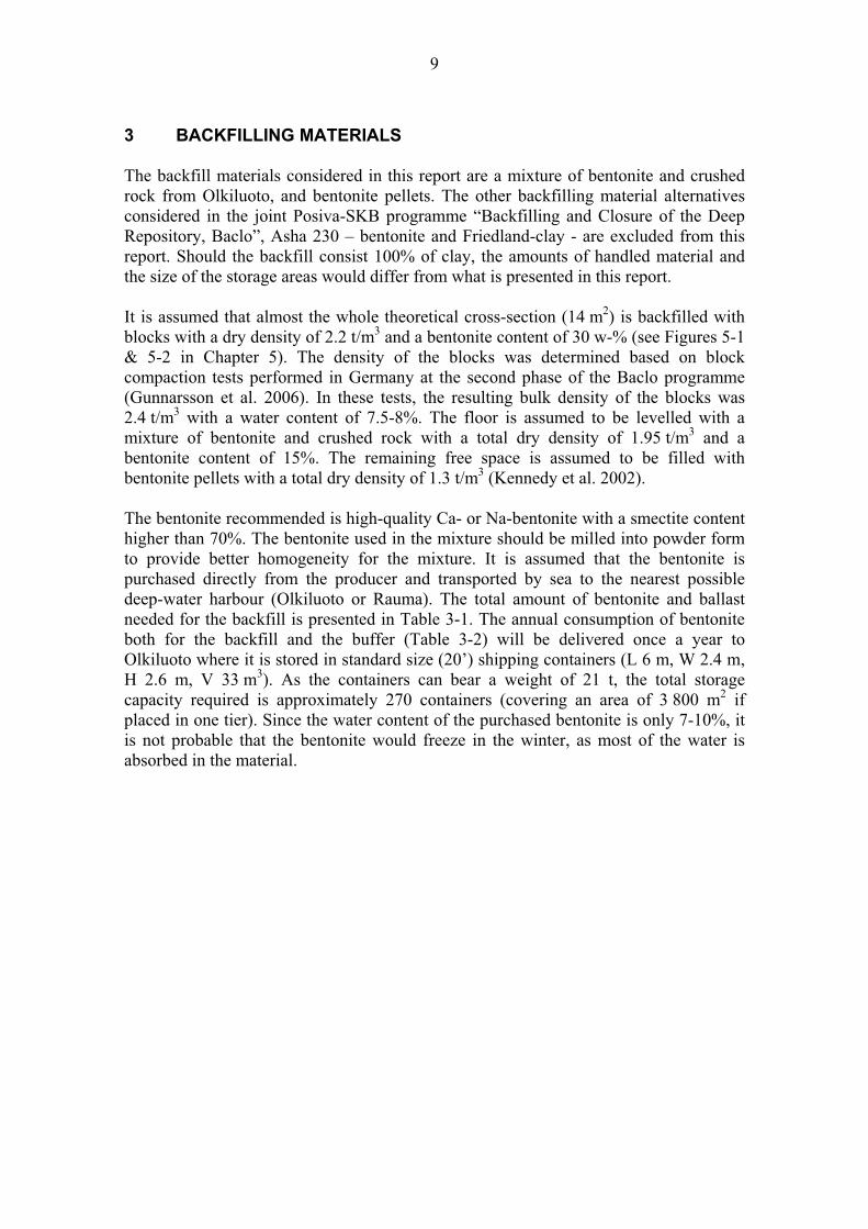
Figure 4-3. Block production plant from above. The production line on the left is for the
buffer blocks and the one on the right is for the backfill blocks. Figure: Paul-Erik
Rönnqvist/Fortum.
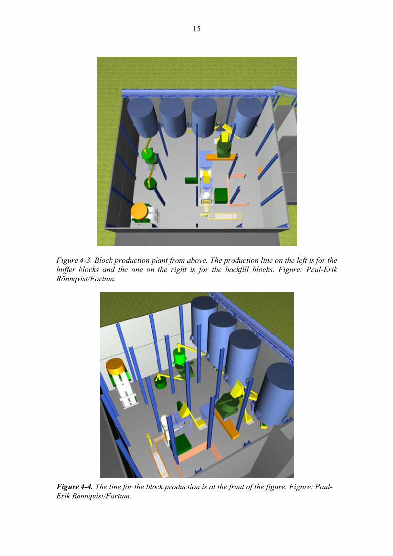
Figure 4-4. The line for the block production is at the front of the figure. Figure: Paul-
Erik Rönnqvist/Fortum.
16
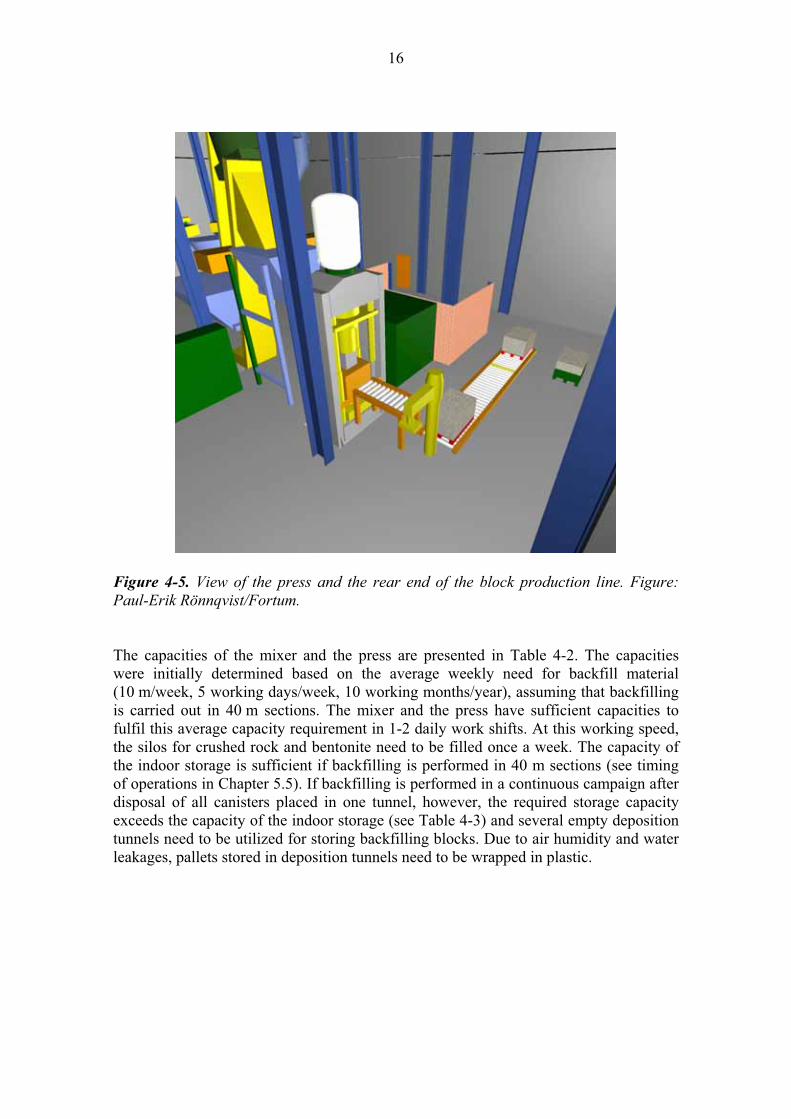
Figure 4-5. View of the press and the rear end of the block production line. Figure:
Paul-Erik Rönnqvist/Fortum.
The capacities of the mixer and the press are presented in Table 4-2. The capacities
were initially determined based on the average weekly need for backfill material
(10 m/week, 5 working days/week, 10 working months/year), assuming that backfilling
is carried out in 40 m sections. The mixer and the press have sufficient capacities to
fulfil this average capacity requirement in 1-2 daily work shifts. At this working speed,
the silos for crushed rock and bentonite need to be filled once a week. The capacity of
the indoor storage is sufficient if backfilling is performed in 40 m sections (see timing
of operations in Chapter 5.5). If backfilling is performed in a continuous campaign after
disposal of all canisters placed in one tunnel, however, the required storage capacity
exceeds the capacity of the indoor storage (see Table 4-3) and several empty deposition
tunnels need to be utilized for storing backfilling blocks. Due to air humidity and water
leakages, pallets stored in deposition tunnels need to be wrapped in plastic.

17
Table 4-2. Average (2 m/day) and effective (5 m/day) daily need for backfilling materials for floor and blocks, and capacities of the mixer and the press. The capacities
per shift were calculated assuming that the effective working time per shift is 7 hours.
Average daily need for backfill materials* (2 m/day, 10 m/week, 400 m/year)
29 m3
69 t(Bulk density 2.4 t/m3)
Effective daily need for backfill materials* (5 m/day)
72 m3
173 t(Bulk density 2.4 t/m3)
Capacity of the mixer 27 m3/h (189 m3/shift) 35 t/h (245 t/shift)(Bulk density of the mix before pressing 1.3 t/m3)
Throughput capacity of the press (LAEIS) 60 strokes per hour 2.2 m3/h (15 m3/shift) 5.2 t/h (36 t/shift) (Bulk density 2.4 t/m3)
Daily capacity of the press (two shifts/day) 840 blocks/day (53 pallets/day) 30 m3
73 t(Bulk density 2.4 t/m3)
* Excluding pellets
Table 4-3. Storage area required for prepared backfilling blocks assuming that
backfilling is performed in a continuous campaign after all canisters have been
installed in the deposition tunnel.
Length of one deposition tunnel (m) 300
Cross-section filled with blocks (m2) 13,5
Volume of blocks in one deposition tunnel (m3) 4 043
Volume of one block (m3) 0.036
Number of blocks required to backfill one deposition tunnel 112 292
Number of working days required to backfill one tunnel 60
Number of blocks produced per working day 840
Number of blocks produced during backfilling of one tunnel 50 400
Required storing capacity (blocks) 61 892
Required storing capacity (pallets) 3 868
Required storing area (m2) 3 714
4.1.3 Process description
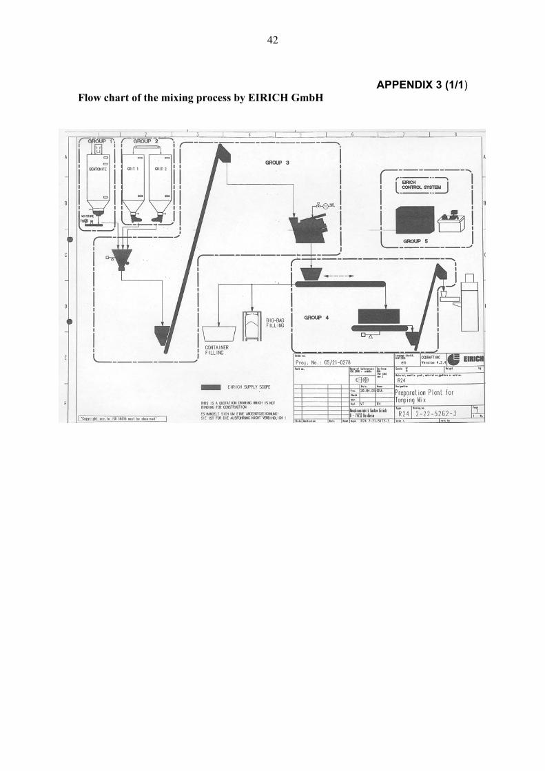
The flow chart for the process is presented in Appendix 2. The components for the
mixture are automatically weighed in the required proportions. The moisture content of
the bentonite fraction is measured, so that the exact amount of water can be added to the
mixture. The volume of one batch mixed at a time is 2.5-3 m3, which means that two
batches per hour are enough to keep the process continuous.

18
The mixed body is discharged from the mixer to a box feeder (50 m3) that functions as a
volume buffer. From the box feeder the mix is transferred into a charger box (2-3 m3)
with the help of a skip hoist. The mixture prepared for floor levelling is prepared in the
same mixer, but the mixture is transferred from the mixer to an intermediate storage silo
(5 m3), from where the material is fed into a vehicle that transports it to the deposition
tunnel.
The press mould is filled directly from the charger box. The press is a uniaxial hydraulic
press (HPF III 630) with a maximum pressing force of 6 300 kN. The maximum
operating pressure of the press is 32 MPa (320 bar). The press is equipped with a
vacuum system for de-aeration of the mix before and during the compaction process.
The maximum pressing capacity is 6.5 strokes per minute, but the actual capacity
depends on the material and on the need for maintenance of the press parts. The
pressing of one backfill block has been estimated to take approximately one minute,
which translates into a capacity of 60 blocks per hour. The dimensions of and the
technical data on the press are presented in Appendix 3. The dimensional accuracy of
the blocks is in the range of +/- 0.5 mm.
The mould is automatically lubricated at every stroke to reduce friction and to restrain
wearing. The lubricating agents normally used in pressing are organic-based oils, the
use of which is not necessarily allowed in the repository, and alternative agents should
be tested for this purpose. Whatever the lubricating agent is, it may affect the saturation
process of the blocks if the surface of the blocks becomes water-repellent. This is
another thing to be tested in the future.
From the press cavity the blocks are pushed onto a conveyor belt and then loaded onto a
pallet placed on a roller conveyor belt. Except for the pallets going to further
processing, the pallets are wrapped in plastic to prohibit degradation due to humidity or
drying. The packing device remains to be designed at further design stages. From the
conveyor belt, the pallets are loaded with a fork truck to the indoor storage, to further
processing (roof blocks) or to a truck that transfers the pallets to the repository level.
The shaping of the roof blocks will be done with a cable wire saw, for example. The
shaping line remains to be designed.
The bentonite used for the pellets can be the same that is used for the buffer blocks.
After mixing, the bentonite is fed to a roller press of the same type that is described e.g.
in Naudorf & Wollenberg (1992). The pellets are packed into 1 t big bags and
transported to the repository level.

19
4.1.4 Quality control
Separate quality control (QC) systems will be used for the bentonite, the crushing of
ballast material, and the block production process. None of the QC systems have been
designed yet, but they should include certain determinations described below.
The smectite-content is the most important property of the bentonite clay purchased
both for backfill and buffer. The smectite-content can be checked indirectly with a
number of relatively simple tests, and with more thorough mineralogical and chemical
laboratory tests. The former tests should include at least determination of liquid limit
and free swelling. These tests should be carried out routinely in a field laboratory as
should also determination of water content and grain size distribution of the clay. A
suitable number of tests would be at least 3 per one ship container (21 t). If the content
of the container does not meet the quality requirements (agreed in the contract with the
producer), the material is to be returned to the producer. Random checks should be
performed to verify the results of the field laboratory test. These tests should include at
least determination of exchangeable cations and the cation exchange capacity (CEC),
semiquantitative mineral composition (with XRD) and chemistry of the bentonite clay
(with ICP-AES, ICP-MS, AAS or XRF). In addition, certain geotechnical material
properties such as hydraulic conductivity, swelling pressure and compaction properties
(Proctor compaction tests) should be determined for the material from time to time. The
number of random checks should be at least 50 a year, i.e. one random test per 100 t of
material.
The crushing process is adjusted on the basis of the properties of the feed and the
specified grain size distribution and grain shape. Therefore, the material properties of
the feed and the ballast are checked regularly during the crushing process.
The water content of the mix is automatically adjusted on the basis of the water content
of the bentonite. A system that automatically measures the water content of the ballast
should be considered for the system, since there can be remarkable variations also in the
water content of the ballast (especially if it is stored outside). Another possibility is to
check the water content of the ballast and the mix by sampling at regular intervals. All
block pallets will be visually inspected before the are wrapped in plastic. Random
checks can be performed to measure the dimensions of the blocks.
4.2 Other above ground facilities
The other facilities required for the block concept are already discussed in Chapter 3,
but as a summary they are:
- Storage area for bentonite (backfill & buffer)
- Storage area for blasted stones and area where the crushing of blasted stones takes
place. The crushing equipment can be either movable or fixed.
- A parking area/garage for the vehicles that transport the blocks to the repository
level.

20
4.3 Logistics
The annual consumption of bentonite (~6 000 t) will be delivered once a year to the
nearest deep water harbour. This amount can be transported with a small bulk cargo
ship (L ~100 m, W ~20 m and draught ~7.5 m).
The two silos for crushed rock and the one silo for bentonite (100 m3 each) need to be
filled approximately once a week, since the weekly need is 100 t (100 m3) for bentonite
and 240 t (180 m3) for crushed rock. The crushed rock will be transported using a truck
with a loading capacity of 20 t. Bentonite can be transported either with the same truck
(if the bentonite is packed into 1 t big bags) or with a tank truck (in case of bulk
material). The transports are supposed to take approximately 1-2 work shifts per week.
The transports of pallets inside the block pressing plant will be implemented with a
forklift truck. A forklift truck will also be used for loading the pallets on a truck for
transport to the repository level.
21
5 INSTALLATION OF BACKFILL MATERIALS
The underground operations associated with tunnel backfilling are described in the
following Chapters. The durations and the timing of the operations are discussed in
Chapter 5.5.
5.1 Preparations
5.1.1 Dismantling of tunnel infra
Based on previous plans (e.g. Kukkola 2004), the deposition tunnel floor is covered
with concrete plates that are installed on a layer of crushed rock to provide a stable base
for the drilling of the deposition holes and deposition of the canister. This cover as well
as cables for electricity, lighting, ventilation and all other equipment mounted in the
tunnel need to be removed. Loose rocks on the roof as well as mesh reinforcements,
shotcrete and the caps of rock bolts (Kukkola 2004) need to be removed. When all this
has been done, the rock surface is cleaned with a high-pressure washer or by vacuuming
(Kukkola 2004). If the tunnel walls are washed, care should be taken that no water runs
into the deposition holes. It is possible that some of the reinforcement (shotcrete, mesh
etc.) needs to be left in the tunnel due to occupational safety. This should not
compromise the requirements set for the tunnel backfill, as long as the reinforcements
are not continuous.
In case the buffer is protected with a plastic cover, the plastic cover needs to be
removed by pulling or by means of compressed air.
5.1.2 Levelling of deposition tunnel floor
It is assumed that the average thickness of the floor layer is 250 mm (150 mm above the
theoretical) as presented in Figure 5-2. The main requirements for the tunnel floor are:
- Provide a smooth enough surface to allow installation of blocks without any large
gaps left between the blocks.
- Provide a high enough bearing capacity to bear the weight of the installation device
(10-15 t) and the blocks without breaking. Should the floor be installed prior to the
drilling of the deposition holes and canister deposition, the material shall bear the
load of the drilling equipment and the canister transportation vehicle at full load
(68 t, 25 t/m2).
- No water-conducting pathways should be formed in the tunnel floor. Therefore, the
hydraulic conductivity of the floor material should be <1E-10 m/s and contact
between the material and the rock should be tight.

22
There are three alternatives for the levelling of the tunnel floor:
- Mechanical levelling of the floor, e.g. with wire sawing or with a cold planer. The
advantages of mechanical levelling would be that it could be carried out prior to the
drilling of the deposition holes, no extra foreign materials would be left in the tunnel
and the process is insensitive to water leakages. However, it remains to be tested
whether mechanical levelling is feasible for this application.
- Levelling the floor with a mixture of bentonite and crushed rock (15:85): the material
is rigid enough to bear the load of the block placing equipment, but not rigid enough
to bear the load of the canister transportation vehicle. The hydraulic conductivity
criterion is fulfilled, if the material is compacted to at least 95% of its maximum dry
density determined with the Proctor compaction test (Keto et al. 2006). In practice
this means that the target dry density is approximately 2 000 kg/m3. This density can
be achieved if the material is compacted with a heavy roller. The disadvantages of
the material are its limited bearing capacity and sensitivity to leakage waters. For this
reason levelling has to be carried out in short sections just before the blocks are
installed.
- The third alternative is to use some kind of steel structures to provide a stable base
for piling the blocks. The disadvantage of this alternative is the amount of foreign
material left in the deposition tunnel and possible harmful interaction with EBS.
The alternative based on a mixture of bentonite and crushed rock (installed in 40 m
sections) is considered as a reference alternative in this report. Since the 20 cm thick cap
structure between the backfill and the buffer has not been designed yet, it is assumed
that it consists of pre-compacted bentonite blocks.
5.2 Logistics
The backfill block pallets will be transported to the repository level using a truck with a
loading capacity of 20 t. The number of daily transports depends on the timing of the
backfill operations and on the size of intermediate storages on the repository level.
However, it can be estimated that in the average case one work shift per day is needed
to transport all backfill materials to the repository level.
Transport from the deposition tunnels serving as intermediate storages will be handled
with a forklift truck. Since the assumed installation capacity is six pallets per hour, the
required velocity of the truck is 4-5 km/h, if the distance from the intermediate storage
to the backfilling front is 350-400 m. If the distance is longer, the number of trucks and
personnel required to keep up with the time-schedule is higher (e.g. if the distance is
1 km, three trucks and drivers are required). Before the pallets are brought to the tunnel,
the plastic cover that protects the pallet against degradation during storage needs to be
removed.

23
5.3 Installation of blocks
There are already certain types of devices on the market that could be used for
installation of the blocks, for example reach truck Merlon Roto 33.13 (see Appendix 4).
However, some modifications are required to enable installation of the blocks in the
relatively small deposition tunnel. As there is not enough space to bring the blocks past
the equipment (as there is in the Swedish case), the blocks need to be transported
underneath the equipment on a roller conveyor (see Figure 5-1). The pallet is picked up
from the front of the device with a fork/plate. The pallet is then lifted to the desired
position (see Figure 5-2) and placed by pushing it forward from the top of the plate. It
has been estimated that the average installation time of one pallet would be
approximately 10 minutes. The actual installation rate depends on in which part of the
tunnel the pallet is installed, in the main body of the backfill or in the roof section.
A total of 34 pallets will be installed per the cross-section of the tunnel (see Figure 5-3).
In the roof section of the tunnel, the blocks/pallets are shaped to fit the shape of the
arch. As the block size is relatively small, the tunnel can be filled up to the theoretical
cross-section which translates into a filling degree of ~90%. This is calculated
assuming that the volume filled with pellets is ~1 m2 and the void volume between the
blocks is 3% of the total volume of the blocks. When all the materials are taken into
account, the resulting average dry density is 2 050 – 2 100 kg/m3. Erosion equal to 3%
of the total mass of the backfill (~1 000 kg per tunnel meter) is required to decrease the
average density below 2 000 kg. It can therefore be stated that the average dry density is
sufficient to fulfil the performance requirements set for the backfill (Johannesson &
Nilsson 2006, Gunnarsson et al. 2006). However, the crucial issues are whether the
backfill will eventually reach homogenisation with respect to density and whether there
is a risk that continuous flow paths remain between the blocks and the walls/roof.
Figure 5-1. An example of the block-placing device. The pallets are transported
underneath the equipment with a roller conveyor. Figure: Paul-Erik Rönnqvist/Fortum.

24
Figure 5-2. Placing a block to the desired position with the telescopic arm of the block-
placing device. Figure: Paul-Erik Rönnqvist/Fortum.
The pallets will be installed in such a manner that no continuous straight joints are
formed trough the backfill (Fig. 5-3). This together with the small block size may have
an advantageous effect on various saturation related processes, such as evenness of
saturation and limited erosion between adjacent blocks. Saturation, erosion, formation
of flow channels (piping) and self-healing of piping channels will be investigated
further at the third phase of the Baclo programme. Based on studies carried out at the
second phase (Sandén & Börgesson 2006), piping and erosion will most likely occur in
the pellet-filled zone where water meets the weakest flow resistance.

25
Figure 5-3. Cross-section of the tunnel filled with blocks. The total number of pallets per cross-section is 34. The area filled with blocks is 13.5 m
2, the area covered with
floor is 0.9 m2 and the area covered with pellets is 1.0 m
2. Figure: Paul-Erik
Rönnqvist/Fortum.
5.4 Installation of pellet fill
The bentonite pellets can be installed with centrifugal pellet throwing equipment
(Gunnarsson et al. 2006) or with a pneumatic system (Kennedy et al. 2005). A prototype
of centrifugal pellet throwing equipment has been tested by SKB (Gunnarsson et al.
2006). Although the design was very preliminary, the system seemed to be adequately
feasible for installation of the pellets. A more sophisticated design of the equipment
remains to be developed.
26
5.5 Timing of operations
The scheduling of the backfilling operations is based on the assumption that the number
amount of canisters disposed of annually is 40 and the average distance between the
canisters is 10 m. This means that one approximately 300-meter long backfilling tunnel
and a 100 m long section of the following tunnel are backfilled every year. The
construction of the plug structure at the deposition tunnel entrance is not taken into
account in the time-schedules.
There are three alternatives for the timing of the backfilling operation in the deposition
tunnels. The first alternative is to dispose of the canisters and to install the backfill in
40-metre sections (5 working days per week, 10 moths per year) as presented in
Kukkola (2004). The other two options are based on the whole tunnel being backfilled
at once, working either five or seven days a week. In the latter two alternatives it has
been assumed that there is a plastic wrapping around the buffer blocks, which shall be
removed prior to backfilling.
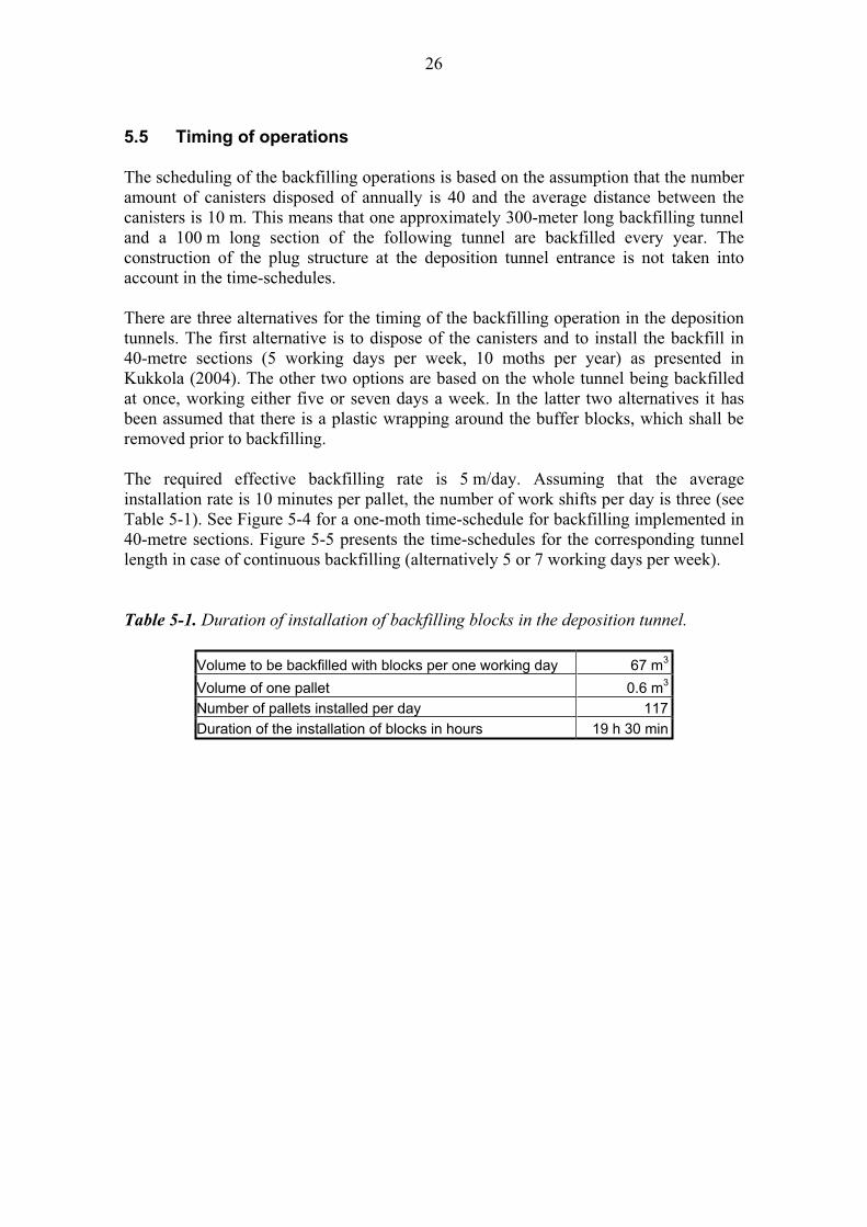
The required effective backfilling rate is 5 m/day. Assuming that the average
installation rate is 10 minutes per pallet, the number of work shifts per day is three (see
Table 5-1). See Figure 5-4 for a one-moth time-schedule for backfilling implemented in
40-metre sections. Figure 5-5 presents the time-schedules for the corresponding tunnel
length in case of continuous backfilling (alternatively 5 or 7 working days per week).
Table 5-1. Duration of installation of backfilling blocks in the deposition tunnel.
Volume to be backfilled with blocks per one working day 67 m3
Volume of one pallet 0.6 m3
Number of pallets installed per day 117
Duration of the installation of blocks in hours 19 h 30 min

27
Figure 5-4. Time-schedule for deposition of four canisters and backfilling of the tunnel
in 40-metre long sections (5 working days per week).
Figure 5-5. Time-schedule for continuous backfill alternatively for five or seven days a
week. It is assumed that the tunnel floor is installed in 40-metre sections.
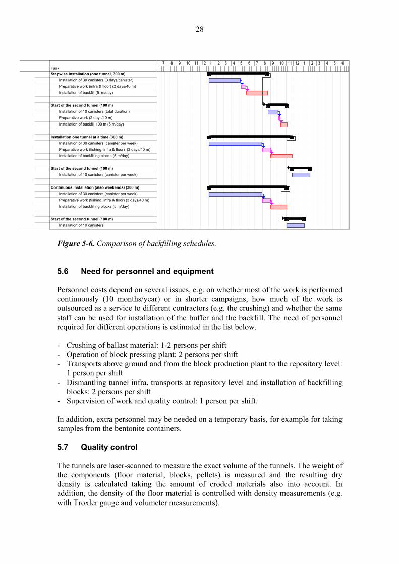
A comparison of time-schedules for disposing of 40 canisters per year (with the three
different backfilling alternatives) is presented in Figure 5-6. The total duration of
disposal operations is longer in the two continuous backfilling alternatives, since the
average production capacity of the canisters is only one per week. In terms of how long
the tunnel will stay open during the backfilling operation, campaign type backfilling is
preferable, as in the discontinuous alternative the tunnels are open for 7.5 months while
in the other two alternatives the tunnels are open for either for 3 or 4 moths. However,
as campaign type backfilling prolongs the total disposal time-schedule and requires
large storages for the backfill blocks, the advantages of campaign type backfilling need
to be evaluated carefully. Another important thing to be considered is that in campaign
type backfilling the deposition holes will be uncovered for a significantly longer time
than in the discontinuous alternative.
Task
Disposal of 4 canisters
Preparation of a disposal hole (1)
Installation of buffer blocks
Installation of the canister and buffer blocks
Prepartation of a disposal hole (2)
Installation of buffer blocks
Installation of canister and buffer blocks
Preparation of a disposal hole (3)
Installation of buffer blocks
Installation of canister and buffer blocks
Preparation of a disposal hole (4)
Installation of buffer blocks
Installation of a canister and buffer blocks
Backfilling of 40 m
Dismantling of tunnel infra (40 m)
Installation of the tunnel floor (40 m)
Backfilling (5 m/day)
1 2 3 4 5 6
Task
Backfilling of 40 m (no weekend work)
Fishing of plastic covers (4 canisters)
Dismantling of tunnel infra (40 m)
Installation of the tunnel floor (40 m)
Backfilling (5 m/day)
Backfilling of 40 m (continuous)
Fishing of plastic covers (4 canisters)
Dismantling of tunnel infra (40 m)
Installation of the tunnel floor (40 m)
Backfilling (5 m/day)
1 2 3
28
Figure 5-6. Comparison of backfilling schedules.
5.6 Need for personnel and equipment
Personnel costs depend on several issues, e.g. on whether most of the work is performed
continuously (10 months/year) or in shorter campaigns, how much of the work is
outsourced as a service to different contractors (e.g. the crushing) and whether the same
staff can be used for installation of the buffer and the backfill. The need of personnel
required for different operations is estimated in the list below.
- Crushing of ballast material: 1-2 persons per shift
- Operation of block pressing plant: 2 persons per shift
- Transports above ground and from the block production plant to the repository level:
1 person per shift
- Dismantling tunnel infra, transports at repository level and installation of backfilling
blocks: 2 persons per shift
- Supervision of work and quality control: 1 person per shift.
In addition, extra personnel may be needed on a temporary basis, for example for taking
samples from the bentonite containers.
5.7 Quality control
The tunnels are laser-scanned to measure the exact volume of the tunnels. The weight of
the components (floor material, blocks, pellets) is measured and the resulting dry
density is calculated taking the amount of eroded materials also into account. In
addition, the density of the floor material is controlled with density measurements (e.g.
with Troxler gauge and volumeter measurements).
Task
Stepwise installation (one tunnel, 300 m)
Installation of 30 canisters (3 days/canister)
Preparative work (infra & floor) (2 days/40 m)
Installation of backfill (5 m/day)
Start of the second tunnel (100 m)
Installation of 10 canisters (total duration)
Preparative work (2 days/40 m)
Installation of backfill 100 m (5 m/day)
Installation one tunnel at a time (300 m)
Installation of 30 canisters (canister per week)
Preparative work (fishing, infra & floor) (3 days/40 m)
Installation of backfilling blocks (5 m/day)
Start of the second tunnel (100 m)
Installation of 10 canisters (canister per week)
Continuous installation (also weekends) (300 m)
Installation of 30 canisters (canister per week)
Preparative work (fishing, infra & floor) (3 days/40 m)
Installation of backfilling blocks (5 m/day)
Start of the second tunnel (100 m)
Installation of 10 canisters
7 8 9 10 11 12 1 2 3 4 5 6 7 8 9 10 11 12 1 2 3 4 5 6

29
6 ASSESSMENT OF THE DESCRIBED BACKFILLING CONCEPT
The calculated tunnel filling degree with blocks + floor material is ~90% (see Chapter
5.3). When all the backfill materials and their initial dry densities are taken into account,
the resulting average dry density is 2 050 – 2 100 kg/m3. This average dry density is
significantly higher than the dry density criterion (1 740-1 890 kg/m3, see Chapter 2)
determined for the 30/70-mixture (Johannesson & Nilsson 2006, Gunnarsson et al.
2006). In theory, the concept can also be considered robust against erosion since
approximately 3% (~1 000 kg per tunnel meter) of the total mass of the backfill material
should have to become eroded before the average dry density would fall below
2 000 kg/m3. However, the question whether backfilling of the tunnels with pre-
compacted blocks consisting of a mixture of bentonite and ballast (30:70) will be able to
fulfil the criteria set for backfill also in practice, depends on the following issues:
- Does the backfill eventually reach homogenisation with respect to density? E.g. is
there a significant difference between the density of the inner and the outer part of
the backfill.
- Is there a risk that continuous flow paths remain between the backfilling blocks
and the rock surface?
- Saturation of the backfill, e.g. risks due to uneven saturation, duration of the
saturation in different inflow scenarios.
- Mechanical interaction between the backfill and the buffer bentonite in different
saturation states.
- What are the long-term consequences of erosion and formation of flow channels
(piping) during the installation and saturation phases?
- Does the 30/70 mixture have sufficient swelling and self-healing capacities to
provide tight contact between the backfill and the rock, and sealing of piping
channels?
- Timing of the backfilling operations. Which alternative is the best in terms of
saturation of the buffer and the backfill.
The open questions listed above have to be studied further with laboratory and large-
scale tests. In addition, the technical feasibility of block backfill concept remains to be
tested in practice.

30

31
7 SUMMARY
This report presents a preliminary process description of backfilling the deposition
tunnels with pre-compacted blocks. The block concept has been developed within the
joint Posiva-SKB backfill project “Backfilling and closure of the deep repository”
(Gunnarsson et al. 2004, 2006). The requirements set for the backfill can be broken
down to specific function indicator criteria concerning hydraulic conductivity, swelling
pressure and compressibility, and to density criteria determined on the basis of
laboratory tests. In addition, there are requirements concerning the technical feasibility
of the backfilling concept. The backfilling rate should be adequately high to allow
disposal of 40 canisters per year.
The block material considered in this report is a mixture of bentonite and ballast
(30:70). Since the block size is relatively small (400 x 300 x 300 mm), it is assumed that
almost the whole theoretical cross-section of the tunnel can be filled with blocks. The
gap between the blocks and the rock surface will be filled with bentonite pellets. The
tunnel floor will be levelled with a 15-25 cm thick layer of a mixture of bentonite and
ballast (15:85) compacted on site with a heavy roller compactor. The amount of
bentonite used annually for the backfill and the buffer will be transported once a year to
Olkiluoto and stored in ship containers. The ballast material will be crushed in Olkiluoto
from the blasted stones quarried from the repository. The maximum grain size of the
ballast material is limited to 10 mm to provide good homogeneity for the mixture.
The block pressing plant consists of silos for bentonite and crushed rock, block
production lines and intermediate storages for both buffer and backfill. The process
includes mixing, filling of the moulds, and pressing, and it is automatic. The water
content of the mix is adjusted on the basis of the water content of the bentonite. The
press has a maximum pressing force of 6 300 kN and an operating pressure of 32 MPa.
It has been estimated that the press is able to produce approximately one backfilling
block per minute, which translates into an average production capacity of 840 blocks
per day (2 work shifts per day). A lubricating agent is used in the pressing process to
decrease friction between the material and the press mould. Since the lubricating agent
is usually oil-based, an alternative agent needs to be tested for the purpose. After
pressing, the blocks are loaded on a pallet (16 blocks per pallet) and the pallet is
wrapped in plastic to avoid degradation and change in water content during storage.
Some of the pallets are processed further to fit the profile of the tunnel roof. The pallets
are loaded on a truck that transports the blocks to the intermediate storage (a deposition
tunnel adjacent to the one being filled) located on the repository level. A forklift truck is
used to transport the pallets from the intermediate storage to the deposition tunnel.
One pallet of backfilling blocks is emplaced at a time in the disposal tunnel. The blocks
are placed in such a manner that no continuous straight joints are formed through the
whole body consisting of backfill blocks. The equipment used for installing the blocks
can be modified from a reach truck. A roller conveyor mounted below the installation
equipment is needed to transport the blocks to the front of the equipment. Since the
estimated average installation rate is 10 minutes per pallet, three shifts per day are
required to keep up with the time-schedule.

32
There are two main alternatives for timing of the operations:
- Installation of the canisters and backfilling in 40-metre sections
- Installation of all canisters placed in one tunnel, followed by backfilling of the whole
tunnel in a separate campaign.
The advantages of the first alternative are that both the installation of 40 canisters and
the backfilling of 400 m can be completed in 10 months and the size of the intermediate
storages required for the canister and the blocks remain small. The disadvantage is that
the operated tunnel will be open for approximately 7.5 months before it is sealed,
leaving the backfill exposed for a relatively long time period. The advantage of the
second alternative is that the backfill will be installed in 3 to 4 months instead of 7.5
months. However, the second alternative has a significant effect on the total duration of
the deposition of 40 canisters and on the size of the intermediate storages. In addition,
the deposition holes would be without backfill cover for seven months.
Taking the blocks and the floor material into account, the tunnel filling degree is ~90%.
The resulting average dry density without any erosion is 2 050-2100 kg/m3, which
fulfils the density requirement with a relatively high safety margin. In addition, the
erosion effect would have to be very high to make the dry density fall below
2 000 kg/m3. The conclusion is that in theory the system is considered as a robust one.
In practice, the crucial issue is whether the backfill will eventually reach
homogenisation with respect to density over the whole cross-section of the tunnel.
Despite the high average density, there is a risk of permanent water conducting
pathways if low-density zones remain between the blocks and the rock. Therefore,
homogenisation and saturation of the block backfill need to be studied further in
laboratory and on tunnel-scale, as need to also erosion, piping and self-healing.
From the technical point of view, issues that require further development and testing
concern:
- Pressing of backfilling blocks
- Alternatives for floor levelling
- Block placing equipment
- Pellet placing equipment.

33
REFERENCES
Gunnarsson, D., Börgesson, L., Keto, P., Tolppanen, P. & Hansen, J. 2004. Backfilling
and Closure of the Deep Repository. Assessment of Backfilling Concepts. Posiva Oy,
Olkiluoto. Working Report 2003-77.
Gunnarsson, D., Morén, L., Sellin, P. & Keto, P. 2006. Deep Repository – engineered
barrier systems. Assessment of backfill materials and methods for deposition tunnels.
Posiva Oy, Olkiluoto. Working Report 2006-64.
Johannesson, L.-E. & Nilsson, U. 2006. Geotechnical properties of canidate backfill
materials for the deep repository. Laboratory tests for determining material
performance. SKB Technical Report (in print).
Kennedy, K., Verfuss, F. & Plötze, M. 2002. Production & emplacement of granular
bentonite material engineered backfill (EB) experiment in opalinus clay Mont Terri
URL, CH. International Meeting, December 9-12.2002, Reims, France. Clays in Natural
and Engineered Barriers for Radioactive Waste Confinement. Abstracts. Pages 271-272.
Keto, P., Kuula-Väisänen, P. & Ruuskanen, J. 2006. Effect of material parameters on
the compactibility of the backfill materials. Posiva Oy, Olkiluoto. Working Report
2006-34.
Kirkkomäki, T. 1999. Backfilling of deposition tunnels. Posiva Oy, Helsinki. Working
Report 1999-75.
Kirkkomäki, T. 2004. Stepwise implementation of the final repository at Olkiluoto.
Posiva Oy, Olkiluoto. Working report 2003-65.
Kukkola, T. 2004. Operating description of Olkiluoto spent fuel repository. Posiva Oy,
Olkiluoto. Working Report 2003-70.
Naudorf, W. & Wollenberg, R. 1992. Herstellung von Bentonit-Granulat mit hoher
Schüttdichte zur Bohrlochabdictung. NAGRA. Technischer Bericht 92-06.
POSIVA 2003. Baseline conditions at Olkiluoto. Posiva Oy, Olkiluoto. POSIVA
2003-02.
Saanio, T., Kirkkomäki, T., Sacklén, N., Autio, J., Kukkola, T. & Raiko, H. 2004. Spent
Nuclear fule repository at Olkiluoto, Preliminary design, Stage 1. Posiva Oy, Olkiluoto.
Working Report 2003-74. (In Finnish)
Sandén, T. & Börgesson, L. 2005. Piping and erosion of backfill materials during
emplacement . SKB Technical Report (in print).
SKB 2005. Interim main report of the SR-Can. Swedish Nuclear Fuel and Waste
Management Co, SKB. SKB Technical Report TR-04-11.

34
Tolppanen, P. 1998. Use and crushing of excavated rock. Posiva Oy, Helsinki. Working
Report 98-40. (In Finnish)

35
LIST OF APPENDICES
Appendix 1. Estimation of the required amount of crushed rock for backfilling
Appendix 2. Lay-out of the block pressing plant. Fortum Nuclear Services.
Appendix 3. Flow chart of the process for mixing the backfill material prior to press.
EIRICH GmbH.
Appendix 4. Cross-section and technical data on the press HPF III 630. LAEIS
GmbH.
Appendix 5. Technical data on a reach truck: Merlo Roto 33.13.

36

37
APPENDIX 1 (1/1)
Estimation of the required amount of crushed rock for backfilling
Need for crushed rock Deposition tunnels
Total volume of deposition tunnels 632 330 m3
Dry density of backfill 2,2 t/m3
Total mass of backfill materials 1 391 126 t
Total mass of crushed rock 973 788 t
Other facilities
Total volume of other facilities 667 670 m3
Dry density of backfill 1,8 t/m3
Total mass of backfill 1 201 806 t
Total mass of crushed rock (85%) 1 021 535 t
Total need for crushed rock 1 995 323 t Mass of rock excavated
Total volume of repository 1 300 000 m3
Dry density of rock 2,65 t/m3
Total mass of rock 3 445 000 t Scenarios on how much rock can be used for backilling
90 % 3 100 500 t
80 % 2 756 000 t
70 % 2 411 500 t
60 % 2 067 000 t
50 % 1 722 500 t
40 % 1 378 000 t
Need from the total amount of rock 58 %

38
APPENDIX 2 (1/4)
Layout of the block production plant: level - 3.60 m.

39
APPENDIX 2 (2/4)
Layout of the block production plant: level + 0.00 m
40
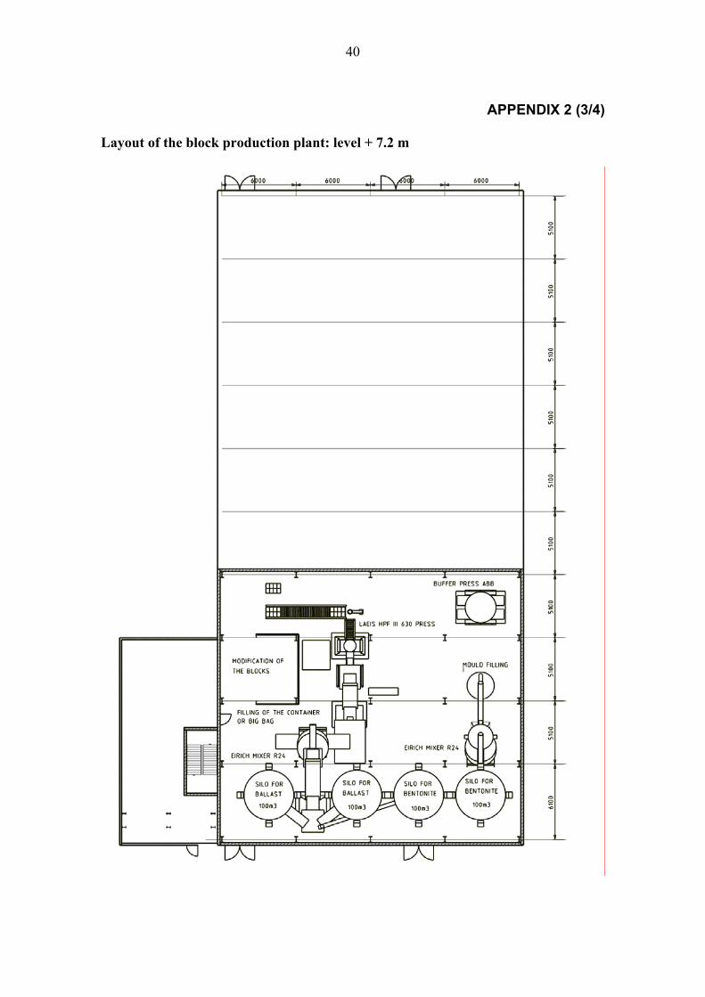
APPENDIX 2 (3/4)
Layout of the block production plant: level + 7.2 m
41
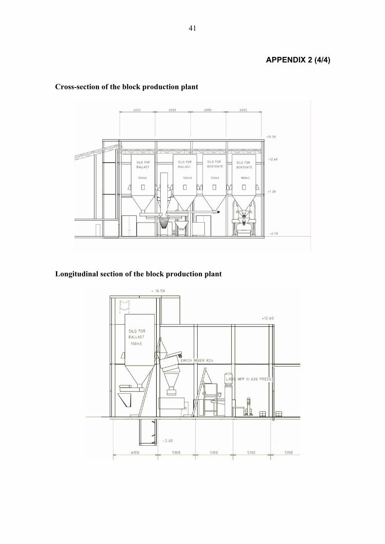
APPENDIX 2 (4/4)
Cross-section of the block production plant
Longitudinal section of the block production plant
42
APPENDIX 3 (1/1)Flow chart of the mixing process by EIRICH GmbH

43
APPENDIX 4 (1/1) For more information visit: http://www.laeis-bucher.com/
INFOTEC
HPF III 630
Machine Specifications
Model HPF III
630
Pressing force in continuous Operation 630
High pressure (bar) 320
Filling depth (mm) 500
Cooling water requirement at a cooling water inlet temperature of
25 °C (m3/h) 1,0-2,0
Total weight (kg) 27.830
Theoretical number of functional strokes (min.-1) 6,5
Hydraulic oil capacity (l) 1.500
Compressed air requirement at 5 bar (l) 50

44
APPENDIX 5 (1/3)

45
APPENDIX 5 (2/3)

46
APPENDIX 5 (3/3)